Embed Size (px)
Citation preview
Operating Instructions D184B132U02
Electromagnetic FlowmeterFXE4000 (COPA-XE/MAG-XE)
Valid for software versions B.12 and higher
Valid for HART software versions X.30 and higher
Model FXE4000-DE41
FXE4000-DE43
FXE4000-DE21
FXE4000-DE23
P R O F I
B U S
PROCESS FIELD BUS
®
Blinder Text
2 FXE4000 (COPA-XE/MAG-XE) D184B132U02
Electromagnetic Flowmeter
FXE4000 (COPA-XE/MAG-XE)
Operating Instructions D184B132U02
07.2006
Manufacturer: ABB Automation Products GmbH Dransfelder Straße 2 D-37079 Göttingen Germany Tel.: +49 551 905-534 Fax: +49 551 905-555 [email protected]
© Copyright 2006 by ABB Automation Products GmbH Subject to change without notice
This document is protected by copyright. It assists the user with the safe and efficient operation of the device. The contents may not be copied or reproduced in whole or in excerpts without prior approval of the copyright holder.
Contents
Contents
D184B132U02 FXE4000 (COPA-XE/MAG-XE) 3
1 Safety....................................................................................................................................................................7
1.1 General Safety Information ............................................................................................................................7 1.2 Intended use...................................................................................................................................................7 1.3 Improper use ..................................................................................................................................................8 1.4 Technical limit values .....................................................................................................................................8 1.5 Allowed Fluids ................................................................................................................................................9 1.6 Warranty provision .........................................................................................................................................9 1.7 Labels and symbols........................................................................................................................................9
1.7.1 Symbols and warnings ............................................................................................................................9 1.7.2 Name Plate / Factory Tag .....................................................................................................................10
1.8 Operator liability ...........................................................................................................................................13 1.9 Personnel qualification .................................................................................................................................13 1.10 Returning devices.........................................................................................................................................13 1.11 Transport safety information ........................................................................................................................13 1.12 Electrical installation safety information .......................................................................................................14 1.13 Operating safety information ........................................................................................................................14 1.14 Maintenance and inspection safety information...........................................................................................14
2 Design and function..........................................................................................................................................15 2.1 Measuring principle ......................................................................................................................................15 2.2 Design ..........................................................................................................................................................16 2.3 Device designs .............................................................................................................................................16
2.3.1 Compact Design (COPA-XE) ................................................................................................................16 2.3.2 Remote Design (MAG-XE)....................................................................................................................17
3 Transport............................................................................................................................................................18 3.1 Inspection .....................................................................................................................................................18 3.2 General information on transport .................................................................................................................18 3.3 Transport of flanged units smaller than DN 450 ..........................................................................................18 3.4 Transport of flanged units larger than DN 400.............................................................................................19
4 Installation..........................................................................................................................................................20 4.1 Installation Requirements.............................................................................................................................20
4.1.1 Electrode axis........................................................................................................................................20 4.1.2 In- and outlet pipe sections ...................................................................................................................20 4.1.3 Vertical connections ..............................................................................................................................20 4.1.4 Horizontal connections..........................................................................................................................20 4.1.5 Free inlet or outlet .................................................................................................................................20 4.1.6 Strongly contaminated fluids.................................................................................................................20 4.1.7 Installation in the vicinity of pumps .......................................................................................................21 4.1.8 Installation in larger size pipelines ........................................................................................................21
4.2 Approved EMF for custody transfer .............................................................................................................22
Contents
4 FXE4000 (COPA-XE/MAG-XE) D184B132U02
4.2.1 Approved flowmeter sizes for “cold water and waste water” ................................................................22 4.2.2 Approved flowmeter sizes for “liquids other than water and chemical fluids” .......................................22 4.2.3 Installation requirements for volume flowrate totalizers........................................................................22
4.3 Installation ....................................................................................................................................................23 4.3.1 Supports for meter sizes larger than DN 400........................................................................................23 4.3.2 General information on installation .......................................................................................................23 4.3.3 Information on 3A conformity ................................................................................................................24 4.3.4 Mounting the measuring tube................................................................................................................26 4.3.5 Torque information ................................................................................................................................27
4.4 Display / housing rotation.............................................................................................................................28 4.4.1 Display rotation .....................................................................................................................................28 4.4.2 Housing rotation ....................................................................................................................................29
4.5 Ground..........................................................................................................................................................29 4.5.1 General information on ground connections .........................................................................................29 4.5.2 Metal pipe with fixed flanges.................................................................................................................29 4.5.3 Metal pipe with loose flanges................................................................................................................30 4.5.4 Non-metallic pipes or pipes with insulating liner ...................................................................................30 4.5.5 Flowmeter primary in stainless steel design, model DE 21 and DE 23 ................................................31 4.5.6 Ground for units with hard or soft rubber liners.....................................................................................31 4.5.7 Ground for devices with protective plates .............................................................................................31 4.5.8 Ground with conductive PTFE grounding plate ....................................................................................31
4.6 Electrical connection ....................................................................................................................................32 4.6.1 Operating the terminals.........................................................................................................................32 4.6.2 Preparing the signal and excitation current cable.................................................................................33 4.6.3 Signal and excitation cable connection for model FXE4000 (MAG-XE)...............................................35 4.6.4 Connection for protection class IP68 ....................................................................................................36 4.6.5 Interconnection Diagrams .....................................................................................................................39
5 Start-up...............................................................................................................................................................46 5.1 Preliminary checks prior to start-up..............................................................................................................46 5.2 Commissioning the unit ................................................................................................................................48
5.2.1 Switching on auxiliary power.................................................................................................................48 5.2.2 Device configuration..............................................................................................................................48
5.3 Commissioning PROFIBUS PA units...........................................................................................................50 5.3.1 Information on voltage/current consumption.........................................................................................53 5.3.2 System integration ................................................................................................................................53
5.4 Commissioning FOUNDATION FIELDBUS units ........................................................................................55 6 Parameterization................................................................................................................................................57
6.1 Display options .............................................................................................................................................57 6.2 Data entry.....................................................................................................................................................58 6.3 Entering data in “short form”.........................................................................................................................60
Contents
D184B132U02 FXE4000 (COPA-XE/MAG-XE) 5
6.4 Parameter overview in “short form”..............................................................................................................61 6.5 Software history............................................................................................................................................71
6.5.1 For transmitters without communication or ACSII communication or PROFIBUS DP .........................71 6.5.2 For transmitters with HART protocol, PROFIBUS PA, FOUNDATION fieldbus communication..........71
7 Error messages .................................................................................................................................................72 8 Maintenance / Repair.........................................................................................................................................74
8.1 Flowmeter primary........................................................................................................................................74 8.2 Cleaning .......................................................................................................................................................75 8.3 Gaskets ........................................................................................................................................................75 8.4 Replacing the transmitter .............................................................................................................................75
9 Spare parts list...................................................................................................................................................76 9.1 Fuses for transmitter electronics ..................................................................................................................76 9.2 Cable set COPA-XE.....................................................................................................................................76 9.3 Spare parts COPA-XE..................................................................................................................................77 9.4 Spare parts transmitter E4 ...........................................................................................................................78
9.4.1 Field-mount housing..............................................................................................................................78 9.4.2 Panel mount housing ............................................................................................................................79 9.4.3 Rail mount housing ...............................................................................................................................79
9.5 Spare parts flowmeter primary .....................................................................................................................80 10 Technical data....................................................................................................................................................81
10.1 Measuring Accuracy.....................................................................................................................................81 10.1.1 Reference Conditions per EN 29104 ....................................................................................................81 10.1.2 Maximum Measurement Error...............................................................................................................81
10.2 Model DE41F, DE41W, DE43F, DE43W .....................................................................................................81 10.2.1 General specifications...........................................................................................................................81 10.2.2 Material load for flanged design model DE41F / DE43F ......................................................................83 10.2.3 Material load for wafer design models DE41W/DE43W .......................................................................84
10.3 Model DE 21, DE21F, DE23, DE23F...........................................................................................................84 10.3.1 General specifications...........................................................................................................................84 10.3.2 Material load for devices with variable process connections DN3 ... 100 (1/10 ... 4") Model
DE21_/DE23_ .......................................................................................................................................85 10.3.3 Material load for flanged design Model DE21F / DE23F ......................................................................85 10.3.4 Material load for wafer design models DE21W / DE 23W ....................................................................86
11 Transmitter.........................................................................................................................................................86 11.1 Specifications: ..............................................................................................................................................86 11.2 Housing Variants ..........................................................................................................................................87 11.3 Converter scale drawing FXE 4000-E4 (MAG-XE) ......................................................................................88
11.3.1 Converter housing and suggested installation......................................................................................88 11.3.2 Converter as panel mount housing .......................................................................................................89 11.3.3 Rail mount housing ...............................................................................................................................89
Contents
6 FXE4000 (COPA-XE/MAG-XE) D184B132U02
12 Appendix ............................................................................................................................................................90 12.1 Permits and certifications .............................................................................................................................90 12.2 Overview of setting parameters and technical design .................................................................................91 12.3 Additional documents ...................................................................................................................................93
13 Index ...................................................................................................................................................................94
Safety
D184B132U02 FXE4000 (COPA-XE/MAG-XE) 7
1 Safety
1.1 General Safety Information
The “Safety” chapter provides an overview of the safety aspects to be observed for the operation of the device.
The device is built based on state-of-the-art technology and is operationally safe. It was tested and left the factory in a proper state. The requirements in the manual as well as the documentation and certificates must be observed and followed in order to maintain this state for the period of operation.
The general safety requirements must be complied with completely during operation of the device. In addition to the general information, the individual chapters of the manual contain descriptions about processes or procedural instructions with specific safety information.
Only the observance of all safety information enables the optimal protection of personnel as well as the environment from hazards and the safe and trouble-free operation of the device.
1.2 Intended use
This device is intended for the following uses:
• To transmit fluid, pulpy or pasty substances with electrical conductivity.
• To measure the flowrate of the operating volume or mass flow units (at constant pressure / temperature), if a mass engeineering unit is selected.
The following items are included in the intended use:
• Read and follow the instructions in this manual.
• Observe the technical ratings (refer to the section “Technical limit values”).
• Use only allowed liquids for measurement (refer to the section “Allowed fluids”)
Safety
8 FXE4000 (COPA-XE/MAG-XE) D184B132U02
1.3 Improper use
The following uses of the device are prohibited:
• Operation as a flexible adapter in piping, e.g., to compensate for pipe offsets, pipe vibrations, pipe expansions, etc.
• Use as a climbing aid, e.g., for assembly purposes.
• Use as a support for external loads, e.g., as a support for pipes, etc.
• Material gain, e.g., by painting over the name plate or adding parts by welding / soldering.
• Material loss, e.g., by drilling the housing.
Repairs, alterations and enhancements or the installation of replacement parts is only permissible as far as described in the manual. Further actions must be verified with ABB Automation Products GmbH. Excluded from this are repairs performed by ABB-authorized specialist shops.
1.4 Technical limit values
The device is designed for use exclusively within the stated values on the name plate and within the technical limit values specified in the data sheets.
The following technical limit values must be observed:
• The permissible pressure (PS) in the permissible fluid temperature (TS) may not exceed the pressure-temperature ratings.
• The maximum operating temperature may not be exceeded.
• The permitted ambient temperature may not be exceeded.
• The housing protection class must be observed.
• The flowmeter primary may not be operated in the vicinity of powerful electromagnetic fields, e.g., motors, pumps, transformers, etc. A minimum spacing of approx. 100 cm should be maintained. For installation on or to steel parts (e.g., steel brackets), a minimum spacing of approx. 100 mm should be maintained (based on IEC801-2 and IECTC77B).
Safety
D184B132U02 FXE4000 (COPA-XE/MAG-XE) 9
1.5 Allowed Fluids
When measuring fluids, the following points must be observed:
• Fluids may only be used if, based on state-of-the-art technology or the operating experience of the user, it is assured that chemical and physical properties of the components coming into contact with the fluids (signal electrodes, ground electrodes, liners and, possibly, process connections, protective plates or protective flanges) are not affected during the operating life.
• Fluids with unknown properties or abrasive agents may only be used if the operator can perform regular and suitable tests to ensure the safe condition of the device.
• Observe the information on the name plate.
1.6 Warranty provision
A use contrary to the device’s stipulated use, disregarding of this manual, the use of under-qualified personnel as well as unauthorized alterations excludes the manufacturer of liability from any resulting damages. The manufacturer’s warranty expires.
1.7 Labels and symbols
1.7.1 Symbols and warnings
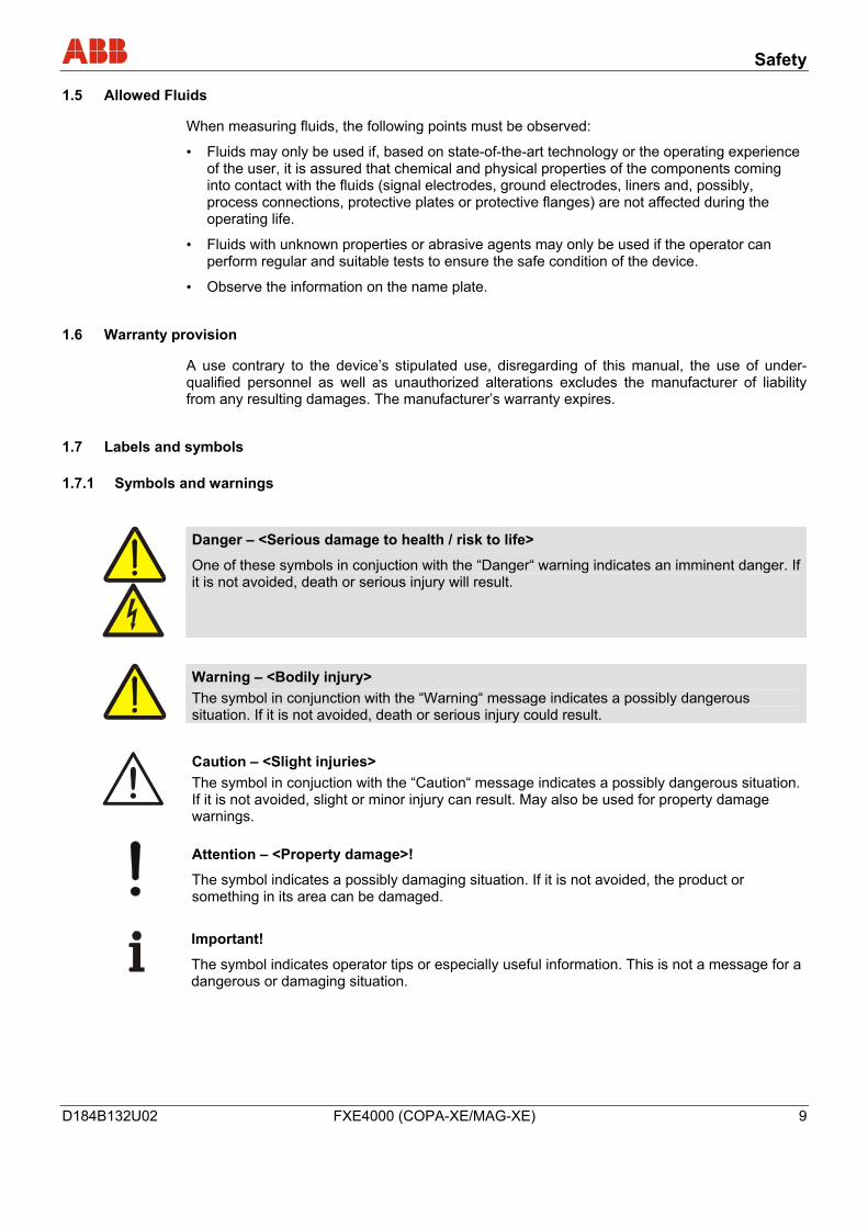
Danger – <Serious damage to health / risk to life>
One of these symbols in conjuction with the “Danger“ warning indicates an imminent danger. If it is not avoided, death or serious injury will result.
Warning – <Bodily injury> The symbol in conjunction with the “Warning“ message indicates a possibly dangerous situation. If it is not avoided, death or serious injury could result.
Caution – <Slight injuries> The symbol in conjuction with the “Caution“ message indicates a possibly dangerous situation. If it is not avoided, slight or minor injury can result. May also be used for property damage warnings.
Attention – <Property damage>!
The symbol indicates a possibly damaging situation. If it is not avoided, the product or something in its area can be damaged.
Important!
The symbol indicates operator tips or especially useful information. This is not a message for a dangerous or damaging situation.
Safety
10 FXE4000 (COPA-XE/MAG-XE) D184B132U02
1.7.2 Name Plate / Factory Tag
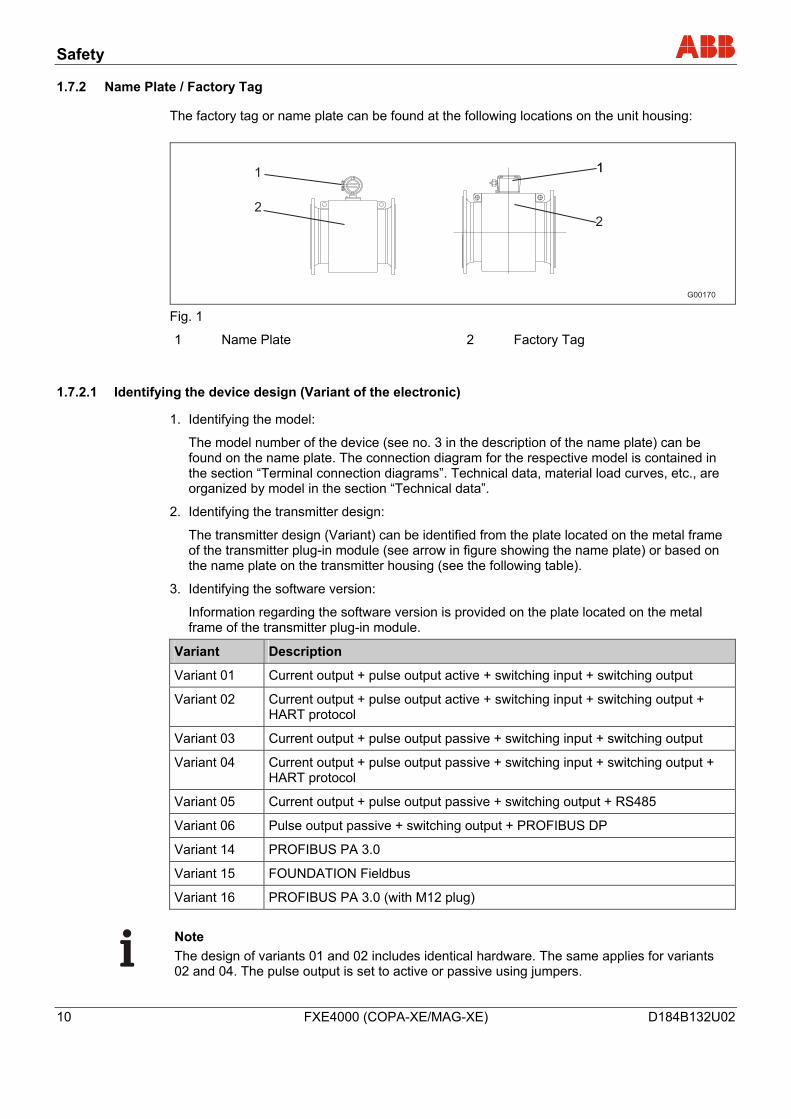
The factory tag or name plate can be found at the following locations on the unit housing:
G00170
2
111
2
Fig. 1
1 Name Plate 2 Factory Tag
1.7.2.1 Identifying the device design (Variant of the electronic)
1. Identifying the model:
The model number of the device (see no. 3 in the description of the name plate) can be found on the name plate. The connection diagram for the respective model is contained in the section “Terminal connection diagrams”. Technical data, material load curves, etc., are organized by model in the section “Technical data”.
2. Identifying the transmitter design:
The transmitter design (Variant) can be identified from the plate located on the metal frame of the transmitter plug-in module (see arrow in figure showing the name plate) or based on the name plate on the transmitter housing (see the following table).
3. Identifying the software version:
Information regarding the software version is provided on the plate located on the metal frame of the transmitter plug-in module.
Variant Description
Variant 01 Current output + pulse output active + switching input + switching output
Variant 02 Current output + pulse output active + switching input + switching output + HART protocol
Variant 03 Current output + pulse output passive + switching input + switching output
Variant 04 Current output + pulse output passive + switching input + switching output + HART protocol
Variant 05 Current output + pulse output passive + switching output + RS485
Variant 06 Pulse output passive + switching output + PROFIBUS DP
Variant 14 PROFIBUS PA 3.0
Variant 15 FOUNDATION Fieldbus
Variant 16 PROFIBUS PA 3.0 (with M12 plug)
Note The design of variants 01 and 02 includes identical hardware. The same applies for variants 02 and 04. The pulse output is set to active or passive using jumpers.
Safety
D184B132U02 FXE4000 (COPA-XE/MAG-XE) 11
1.7.2.2 Name Plate
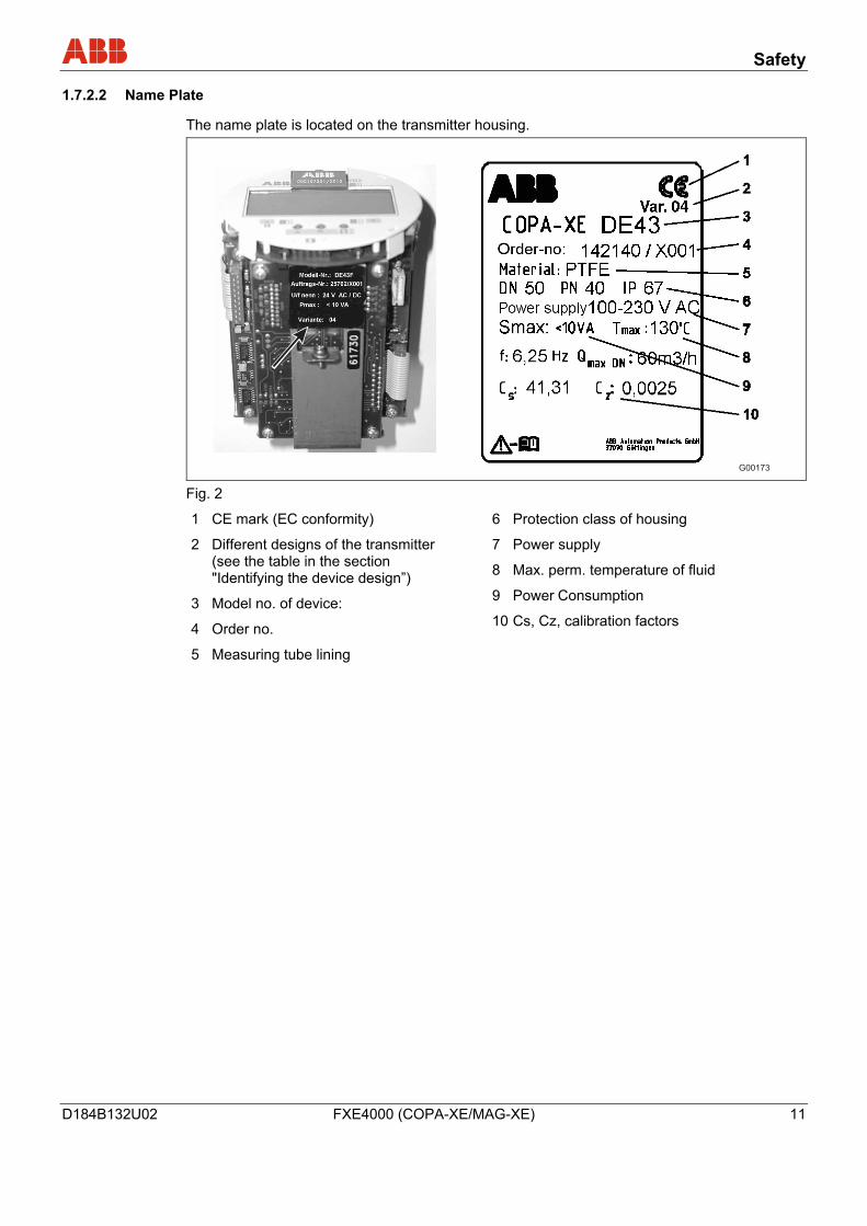
The name plate is located on the transmitter housing.
G00173 Fig. 2
1 CE mark (EC conformity)
2 Different designs of the transmitter (see the table in the section "Identifying the device design”)
3 Model no. of device:
4 Order no.
5 Measuring tube lining
6 Protection class of housing
7 Power supply
8 Max. perm. temperature of fluid
9 Power Consumption
10 Cs, Cz, calibration factors
Safety
12 FXE4000 (COPA-XE/MAG-XE) D184B132U02
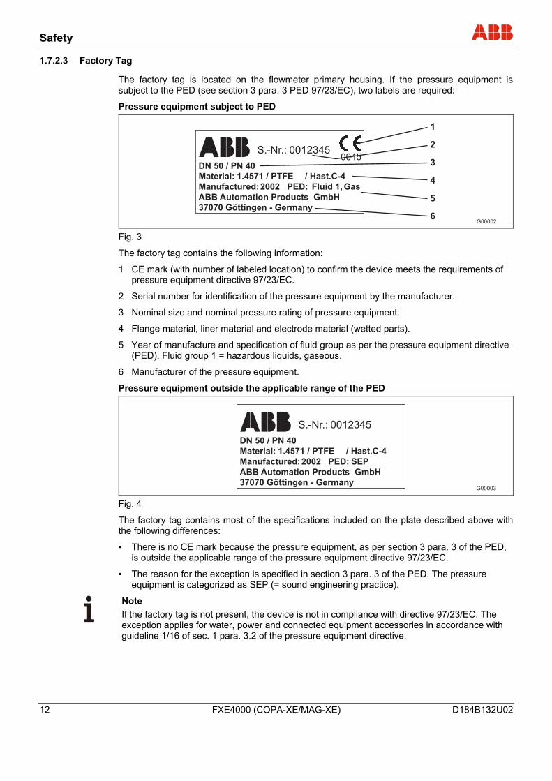
1.7.2.3 Factory Tag
The factory tag is located on the flowmeter primary housing. If the pressure equipment is subject to the PED (see section 3 para. 3 PED 97/23/EC), two labels are required:
Pressure equipment subject to PED
S.-Nr.: 00123450045
DN 50 / PN 40
Material: 1.4571 / PTFE
Manufactured:2002 PED: Fluid 1, Gas
ABB Automation Products GmbH
37070 Göttingen - Germany
/ Hast.C-4
1
2
3
4
5
6G00002
Fig. 3
The factory tag contains the following information:
1 CE mark (with number of labeled location) to confirm the device meets the requirements of pressure equipment directive 97/23/EC.
2 Serial number for identification of the pressure equipment by the manufacturer.
3 Nominal size and nominal pressure rating of pressure equipment.
4 Flange material, liner material and electrode material (wetted parts).
5 Year of manufacture and specification of fluid group as per the pressure equipment directive (PED). Fluid group 1 = hazardous liquids, gaseous.
6 Manufacturer of the pressure equipment.
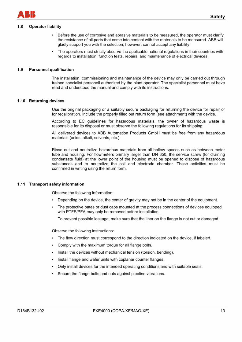
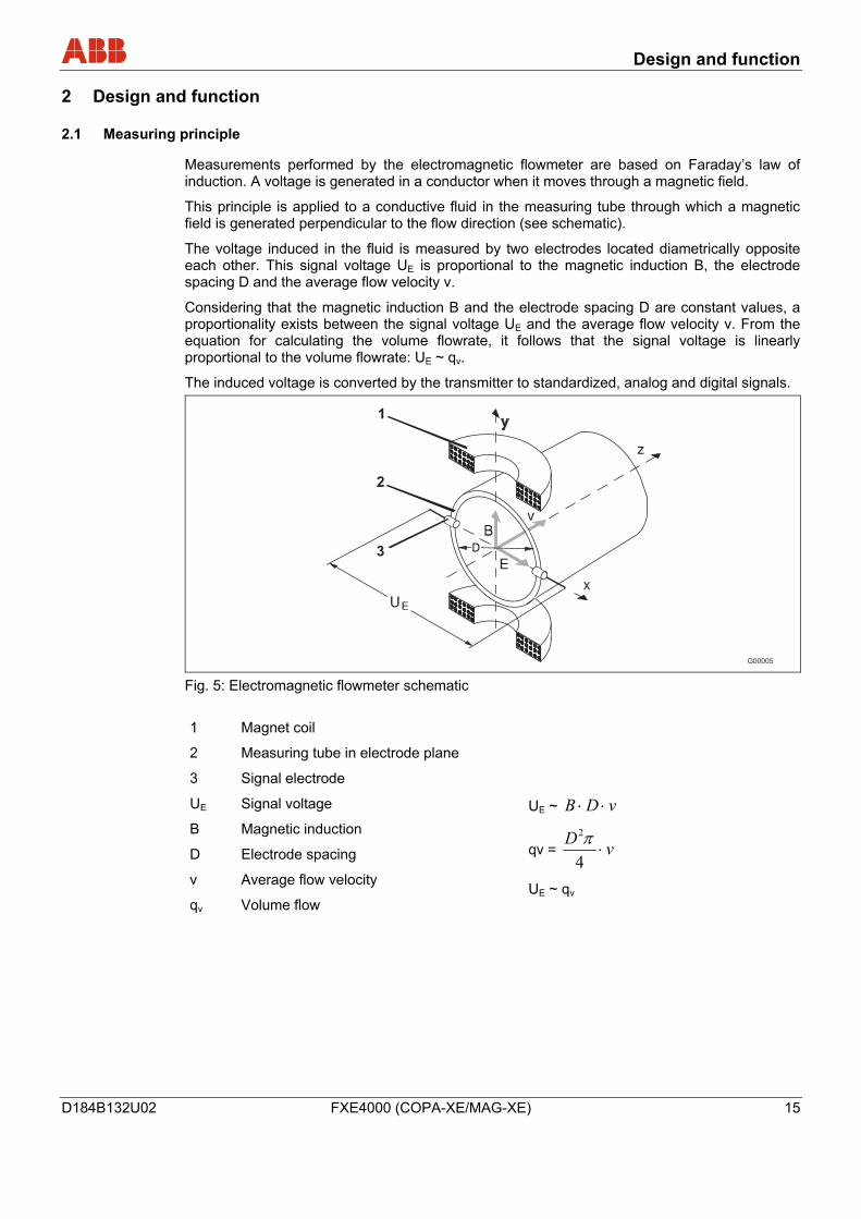
Pressure equipment outside the applicable range of the PED
S.-Nr.: 0012345
DN 50 / PN 40
Material: 1.4571 / PTFE
Manufactured:2002 PED: SEP
ABB Automation Products GmbH
37070 Göttingen - Germany
/ Hast.C-4
G00003 Fig. 4
The factory tag contains most of the specifications included on the plate described above with the following differences:
• There is no CE mark because the pressure equipment, as per section 3 para. 3 of the PED, is outside the applicable range of the pressure equipment directive 97/23/EC.
• The reason for the exception is specified in section 3 para. 3 of the PED. The pressure equipment is categorized as SEP (= sound engineering practice).
Note If the factory tag is not present, the device is not in compliance with directive 97/23/EC. The exception applies for water, power and connected equipment accessories in accordance with guideline 1/16 of sec. 1 para. 3.2 of the pressure equipment directive.
Safety
D184B132U02 FXE4000 (COPA-XE/MAG-XE) 13
1.8 Operator liability
• Before the use of corrosive and abrasive materials to be measured, the operator must clarify the resistance of all parts that come into contact with the materials to be measured. ABB will gladly support you with the selection, however, cannot accept any liability.
• The operators must strictly observe the applicable national regulations in their countries with regards to installation, function tests, repairs, and maintenance of electrical devices.
1.9 Personnel qualification
The installation, commissioning and maintenance of the device may only be carried out through trained specialist personell authorized by the plant operator. The specialist personnel must have read and understood the manual and comply with its instructions.
1.10 Returning devices
Use the original packaging or a suitably secure packaging for returning the device for repair or for recalibration. Include the properly filled out return form (see attachment) with the device.
According to EC guidelines for hazardous materials, the owner of hazardous waste is responsible for its disposal or must observe the following regulations for its shipping:
All delivered devices to ABB Automation Products GmbH must be free from any hazardous materials (acids, alkali, solvents, etc.).
Rinse out and neutralize hazardous materials from all hollow spaces such as between meter tube and housing. For flowmeters primary larger than DN 350, the service screw (for draining condensate fluid) at the lower point of the housing must be opened to dispose of hazardous substances and to neutralize the coil and electrode chamber. These activities must be confirmed in writing using the return form.
1.11 Transport safety information
Observe the following information:
• Depending on the device, the center of gravity may not be in the center of the equipment.
• The protective pates or dust caps mounted at the process connections of devices equipped with PTFE/PFA may only be removed before installation.
To prevent possible leakage, make sure that the liner on the flange is not cut or damaged.
Observe the following instructions:
• The flow direction must correspond to the direction indicated on the device, if labeled.
• Comply with the maximum torque for all flange bolts.
• Install the devices without mechanical tension (torsion, bending).
• Install flange and wafer units with coplanar counter flanges.
• Only install devices for the intended operating conditions and with suitable seals.
• Secure the flange bolts and nuts against pipeline vibrations.
Safety
14 FXE4000 (COPA-XE/MAG-XE) D184B132U02
1.12 Electrical installation safety information
The electrical connection may only be performed by authorized specialists according to the electrical plans.
Comply with electrical connection information in the manual. Otherwise, the electrical protection can be affected.
Ground the measurement system according to requirements.
1.13 Operating safety information
During operation with hot fluids, contact with the surface may result in burns.
Aggressive fluids may result in corrosion and abrasion of the liner or electrodes. As a result, pressurized fluids may escape prematurely.
Due to wear on the flange seal or process connection gaskets (e.g., aseptic threaded pipe connections, Tri-Clamp, etc.), a pressurized medium may escape.
When using internal flat gaskets, these can become embrittled through CIP/SIP processes.
1.14 Maintenance and inspection safety information
Warning – Risk to persons! When the housing cover is open, EMC and protection against contact are suspended. There are electric circuits within the housing which pose a contact risk. The auxiliary power must be switched off before opening the housing cover.
Warning – Risk to persons! The inspection screw (for draining condensate fluid) for devices ≥ DN 450 can be under pressure. The medium which spurts out can cause severe injuries. Depressurize pipes before opening the inspection screw.
Corrective maintenance work may only be performed by trained personnel.
• Depressurize the device and adjoining lines or containers before removing the device.
• Check whether hazardous materials are used as materials to be measured before opening the device. Residual amounts of hazardous material may still be present in the device and could escape when the device is opened.
• As far as provided in the scope of the operational responsibility, check the following items through a regular inspection:
− the pressure-carrying walls / lining of the pressure device
− the measurement-related function
− the leak tightness
− the wear (corrosion)
Design and function
D184B132U02 FXE4000 (COPA-XE/MAG-XE) 15
2 Design and function
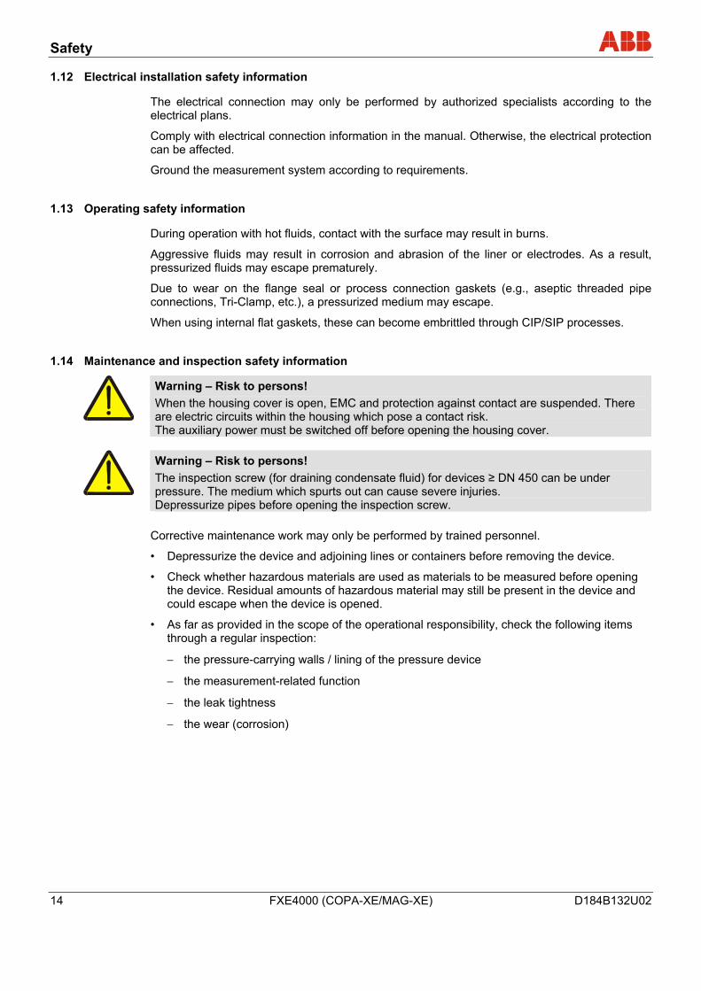
2.1 Measuring principle
Measurements performed by the electromagnetic flowmeter are based on Faraday’s law of induction. A voltage is generated in a conductor when it moves through a magnetic field.
This principle is applied to a conductive fluid in the measuring tube through which a magnetic field is generated perpendicular to the flow direction (see schematic).
The voltage induced in the fluid is measured by two electrodes located diametrically opposite each other. This signal voltage UE is proportional to the magnetic induction B, the electrode spacing D and the average flow velocity v.
Considering that the magnetic induction B and the electrode spacing D are constant values, a proportionality exists between the signal voltage UE and the average flow velocity v. From the equation for calculating the volume flowrate, it follows that the signal voltage is linearly proportional to the volume flowrate: UE ~ qv.
The induced voltage is converted by the transmitter to standardized, analog and digital signals.
G00005
1
2
3
Fig. 5: Electromagnetic flowmeter schematic 1 Magnet coil
2 Measuring tube in electrode plane
3 Signal electrode
UE Signal voltage
B Magnetic induction
D Electrode spacing
v Average flow velocity
qv Volume flow
UE ~ vDB ⋅⋅
qv = vD⋅
4
2π
UE ~ qv
Design and function
16 FXE4000 (COPA-XE/MAG-XE) D184B132U02
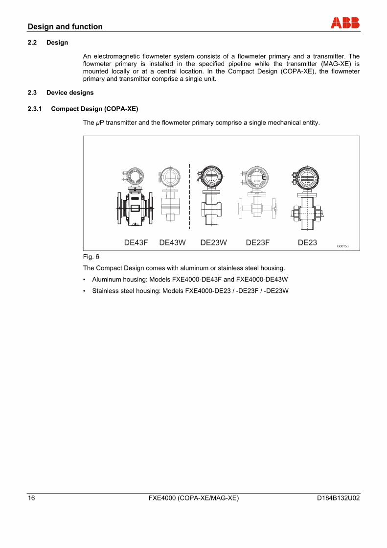
2.2 Design
An electromagnetic flowmeter system consists of a flowmeter primary and a transmitter. The flowmeter primary is installed in the specified pipeline while the transmitter (MAG-XE) is mounted locally or at a central location. In the Compact Design (COPA-XE), the flowmeter primary and transmitter comprise a single unit.
2.3 Device designs
2.3.1 Compact Design (COPA-XE)
The µP transmitter and the flowmeter primary comprise a single mechanical entity.
G00153DE43F DE43W DE23W DE23F DE23
Fig. 6
The Compact Design comes with aluminum or stainless steel housing.
• Aluminum housing: Models FXE4000-DE43F and FXE4000-DE43W
• Stainless steel housing: Models FXE4000-DE23 / -DE23F / -DE23W
Design and function
D184B132U02 FXE4000 (COPA-XE/MAG-XE) 17
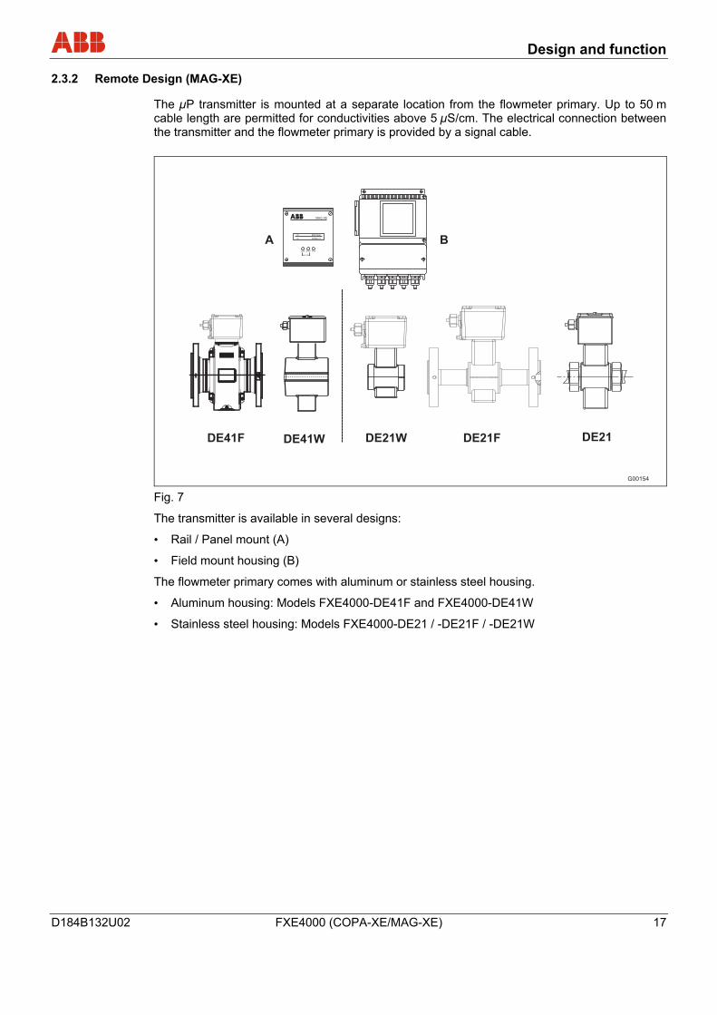
2.3.2 Remote Design (MAG-XE)
The µP transmitter is mounted at a separate location from the flowmeter primary. Up to 50 m cable length are permitted for conductivities above 5 µS/cm. The electrical connection between the transmitter and the flowmeter primary is provided by a signal cable.
G00154
DE41F DE41W DE21W DE21F DE21
MAG XE
>V 205 l/min
>V
DATA STEP C/CE
ENTER
28340 m³
A B
Fig. 7
The transmitter is available in several designs:
• Rail / Panel mount (A)
• Field mount housing (B)
The flowmeter primary comes with aluminum or stainless steel housing.
• Aluminum housing: Models FXE4000-DE41F and FXE4000-DE41W
• Stainless steel housing: Models FXE4000-DE21 / -DE21F / -DE21W
Transport
18 FXE4000 (COPA-XE/MAG-XE) D184B132U02
3 Transport
3.1 Inspection
Check the devices for possible damage that may have occurred from improper transport. Damages in transit must be recorded on the transport documents. All claims for damages must be claimed without delay against the shipper and before the installation.
3.2 General information on transport
Observe the following when transporting the device to the measurement site:
• The center of gravity may not be in the center of the device.
• The protective pates or dust caps mounted at the process connections of devices equipped with PTFE/PFA may only be removed before installation. To prevent possible leakage, make sure that the liner is not cut or damaged.
• Flanged units may not be lifted by the transmitter housing or terminal box.
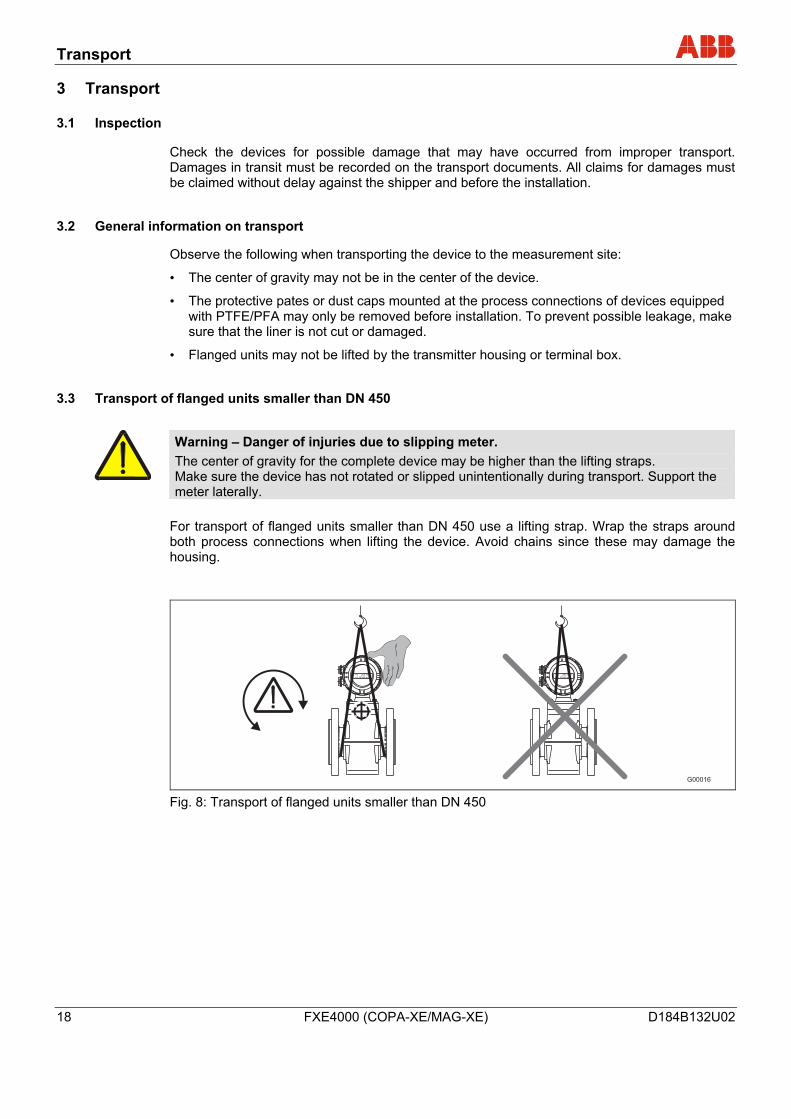
3.3 Transport of flanged units smaller than DN 450
Warning – Danger of injuries due to slipping meter. The center of gravity for the complete device may be higher than the lifting straps. Make sure the device has not rotated or slipped unintentionally during transport. Support the meter laterally.
For transport of flanged units smaller than DN 450 use a lifting strap. Wrap the straps around both process connections when lifting the device. Avoid chains since these may damage the housing.
G00016
>V 205 l/min
>V 28340 m3
>V 205 l/min
>V 28340 m3
Fig. 8: Transport of flanged units smaller than DN 450
Transport
D184B132U02 FXE4000 (COPA-XE/MAG-XE) 19
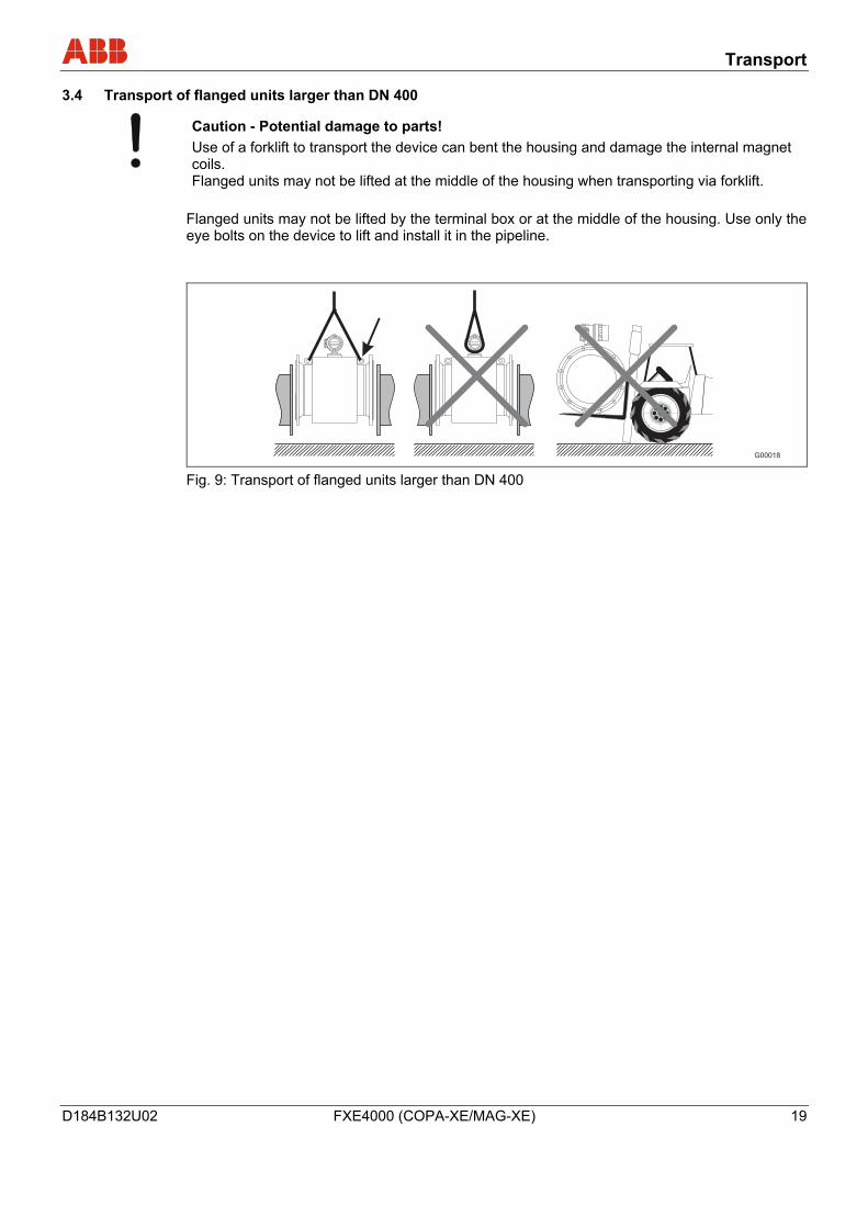
3.4 Transport of flanged units larger than DN 400
Caution - Potential damage to parts! Use of a forklift to transport the device can bent the housing and damage the internal magnet coils. Flanged units may not be lifted at the middle of the housing when transporting via forklift.
Flanged units may not be lifted by the terminal box or at the middle of the housing. Use only the eye bolts on the device to lift and install it in the pipeline.
G00018 Fig. 9: Transport of flanged units larger than DN 400
Installation
20 FXE4000 (COPA-XE/MAG-XE) D184B132U02
4 Installation Wechsel ein-auf zweispaltig
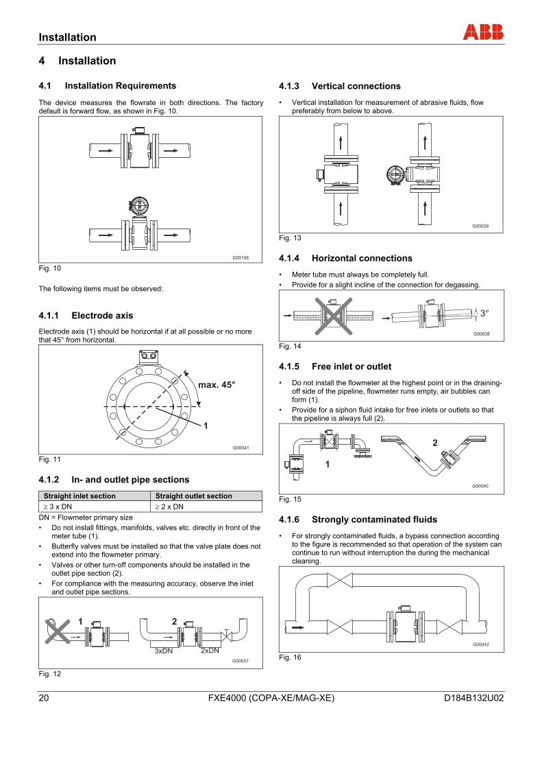
4.1 Installation Requirements
The device measures the flowrate in both directions. The factory default is forward flow, as shown in Fig. 10.
G00156 Fig. 10 The following items must be observed:
4.1.1 Electrode axis
Electrode axis (1) should be horizontal if at all possible or no more that 45° from horizontal.
G00041
max. 45°
1
Fig. 11
4.1.2 In- and outlet pipe sections
Straight inlet section Straight outlet section ≥ 3 x DN ≥ 2 x DN
DN = Flowmeter primary size • Do not install fittings, manifolds, valves etc. directly in front of the
meter tube (1). • Butterfly valves must be installed so that the valve plate does not
extend into the flowmeter primary. • Valves or other turn-off components should be installed in the
outlet pipe section (2). • For compliance with the measuring accuracy, observe the inlet
and outlet pipe sections.
G00037
1 2
3xDN 2xDN
Fig. 12
4.1.3 Vertical connections
• Vertical installation for measurement of abrasive fluids, flow preferably from below to above.
G00039 Fig. 13
4.1.4 Horizontal connections
• Meter tube must always be completely full. • Provide for a slight incline of the connection for degassing.
G00038
3°
Fig. 14
4.1.5 Free inlet or outlet
• Do not install the flowmeter at the highest point or in the draining- off side of the pipeline, flowmeter runs empty, air bubbles can form (1).
• Provide for a siphon fluid intake for free inlets or outlets so that the pipeline is always full (2).
G00040
1
2
Fig. 15
4.1.6 Strongly contaminated fluids
• For strongly contaminated fluids, a bypass connection according to the figure is recommended so that operation of the system can continue to run without interruption the during the mechanical cleaning.
G00042 Fig. 16
Installation
D184B132U02 FXE4000 (COPA-XE/MAG-XE) 21
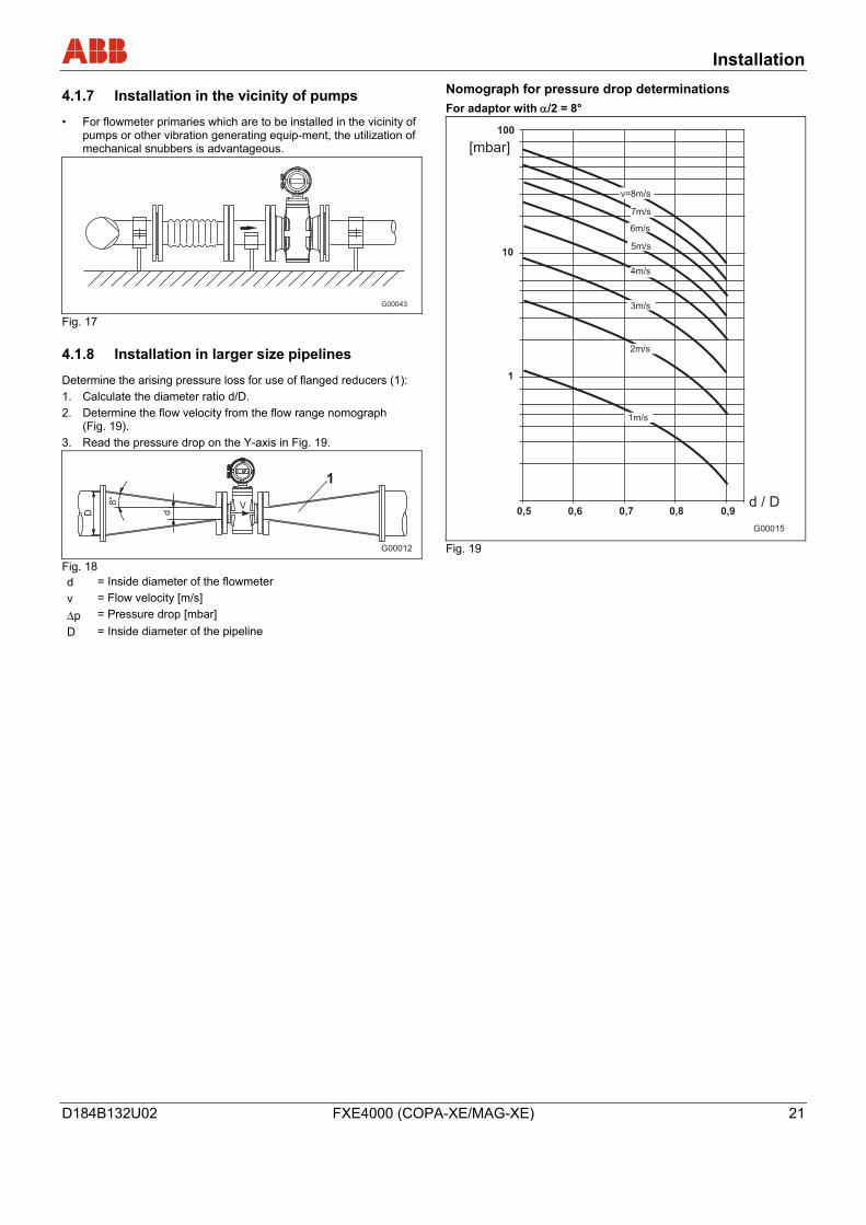
4.1.7 Installation in the vicinity of pumps
• For flowmeter primaries which are to be installed in the vicinity of pumps or other vibration generating equip-ment, the utilization of mechanical snubbers is advantageous.
G00043 Fig. 17
4.1.8 Installation in larger size pipelines
Determine the arising pressure loss for use of flanged reducers (1): 1. Calculate the diameter ratio d/D. 2. Determine the flow velocity from the flow range nomograph
(Fig. 19). 3. Read the pressure drop on the Y-axis in Fig. 19.
Fig. 18 d = Inside diameter of the flowmeter v = Flow velocity [m/s] Δp = Pressure drop [mbar] D = Inside diameter of the pipeline
Nomograph for pressure drop determinations For adaptor with α/2 = 8°
Fig. 19
Installation
22 FXE4000 (COPA-XE/MAG-XE) D184B132U02
4.2 Approved EMF for custody transfer
Approvals The design of the measurement instrument “Electromagnetic volume flowrate totalizer with electrical counter” has been approved by the National Institute for Science and Technology (Physikalisch-Technischen Bundesanstalt) in Braunschweig, Germany. The following approvals have been granted for the volume flowrate totalizer which consists of a flowmeter primary and a converter:
6.221 87.12
Electromagnetic volume flowrate totalizer with a Class “A and B” electrical counter for cold water and waste water
5.721 87.05
Electromagnetic volume flowrate totalizer with electrical counter for liquids other than water
Appendix (EO6) or Appendix 5 (EO5) of the certification regulations of 1988 apply to the electromagnetic volume flowrate totalizer with electrical counter. Certification The electromagnetic volume flowrate totalizer is certified on the test stands in Göttingen, Germany which have been approved for certification calibrations. After the calibration has been completed, the parameters which impact the certification regulations, can only be changed in the presence of a certification agent.
4.2.1 Approved flowmeter sizes for “cold water and waste water”
DN Min. Allow. Flow Range End Value (approx. 2 m/s)
Max. Allow. Flow Range End Value (approx. 10 m/s)
25 32 40
2,4 5 9
m3/h m3/h m3/h
12 25 45
m3/h m3/h m3/h
40 65 80
14 24 36
m3/h m3/h m3/h
70 120 180
m3/h m3/h m3/h
100 125 150
56 84 128
m3/h m3/h m3/h
280 420 640
m3/h m3/h m3/h
000 250 300
220 360 500
m3/h m3/h m3/h
1100 1800 2500
m3/h m3/h m3/h
350 400 500
700 900 1420
m3/h m3/h m3/h
3500 4500 7100
m3/h m3/h m3/h
600 700 800
2000 2800 3600
m3/h m3/h m3/h
10000 14000 18000
m3/h m3/h m3/h
900 1000
4600 5600
m3/h m3/h
23000 28000
m3/h m3/h
4.2.2 Approved flowmeter sizes for “liquids other than water and chemical fluids”
Flowmeter Size and Maximum Allowable Flowrates DN Qmax Liter/min 25 32 40 50
Selectively Selectively Selectively Selectively
60 ... 200 100 ... 400 150 ... 750 250 ... 1000
In steps of In steps of In steps of In steps of
10 20 50 50
65 80
100 150
Selectively Selectively Selectively Selectively
400 ... 2000 700 ... 3000 900 ... 4500 2000 ... 10000
In steps of In steps of In steps of In steps of
100 100 100 500
Minimum Flowrates and Fluids DN Minimum Flowrate Liter Fluid 25 32 40 50
20 20 20
200
Beer Beer Beer, Milk Beer, Wort
65 80
100 150
500 500
2000 2000
Milk, Wort, Beer Milk, Wort, Beer Brine, Wort Brine
Min.flow range:approx. 2.5 m/s. Max. flow range approx. 10 m/s. The actual flow ranges must be in accord with the values listed in the tables. Subsequent range changes require a new calibration on an agency certified test stand.
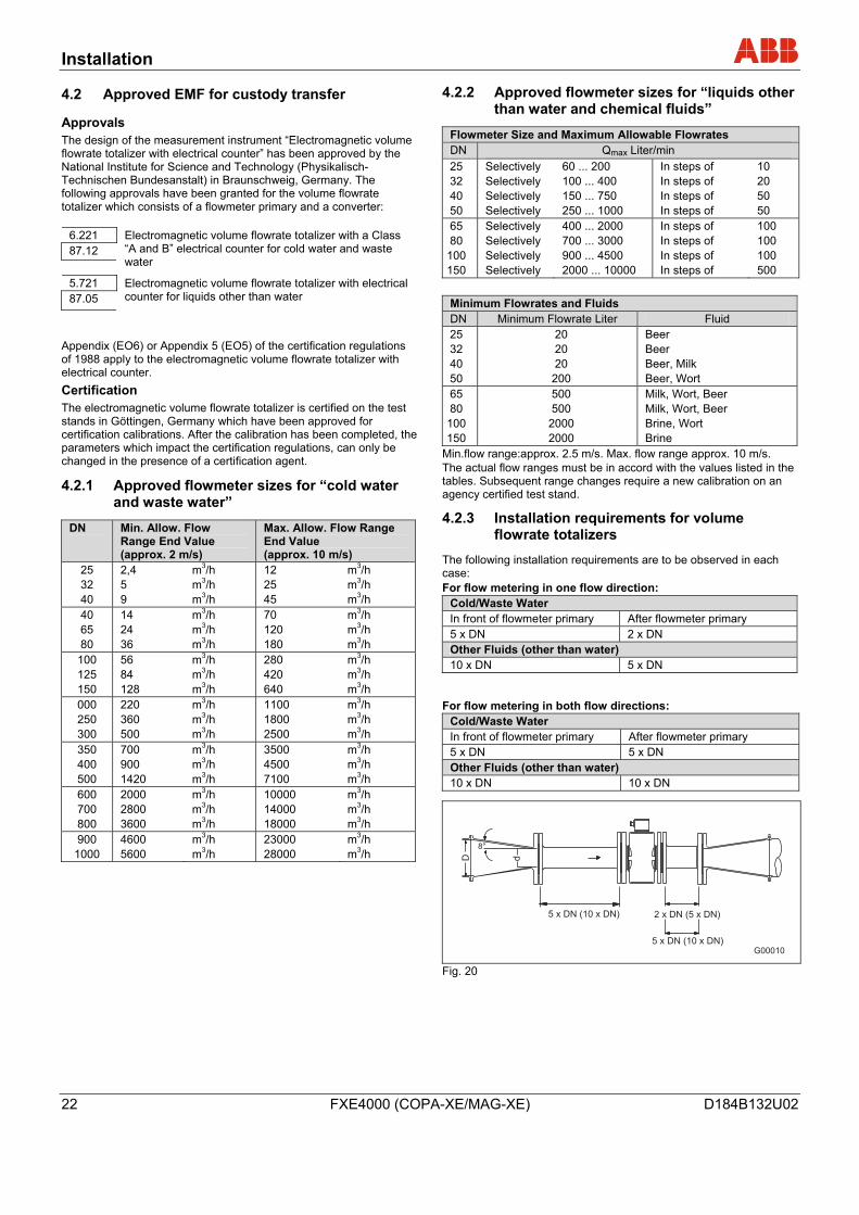
4.2.3 Installation requirements for volume flowrate totalizers
The following installation requirements are to be observed in each case: For flow metering in one flow direction:
Cold/Waste Water In front of flowmeter primary After flowmeter primary 5 x DN 2 x DN Other Fluids (other than water) 10 x DN 5 x DN
For flow metering in both flow directions:
Cold/Waste Water In front of flowmeter primary After flowmeter primary 5 x DN 5 x DN Other Fluids (other than water) 10 x DN 10 x DN
G00010
D d
8°
5 x DN (10 x DN) 2 x DN (5 x DN)
5 x DN (10 x DN)
Fig. 20
Wechsel ein-auf zweispaltig
Installation
D184B132U02 FXE4000 (COPA-XE/MAG-XE) 23
4.3 Installation
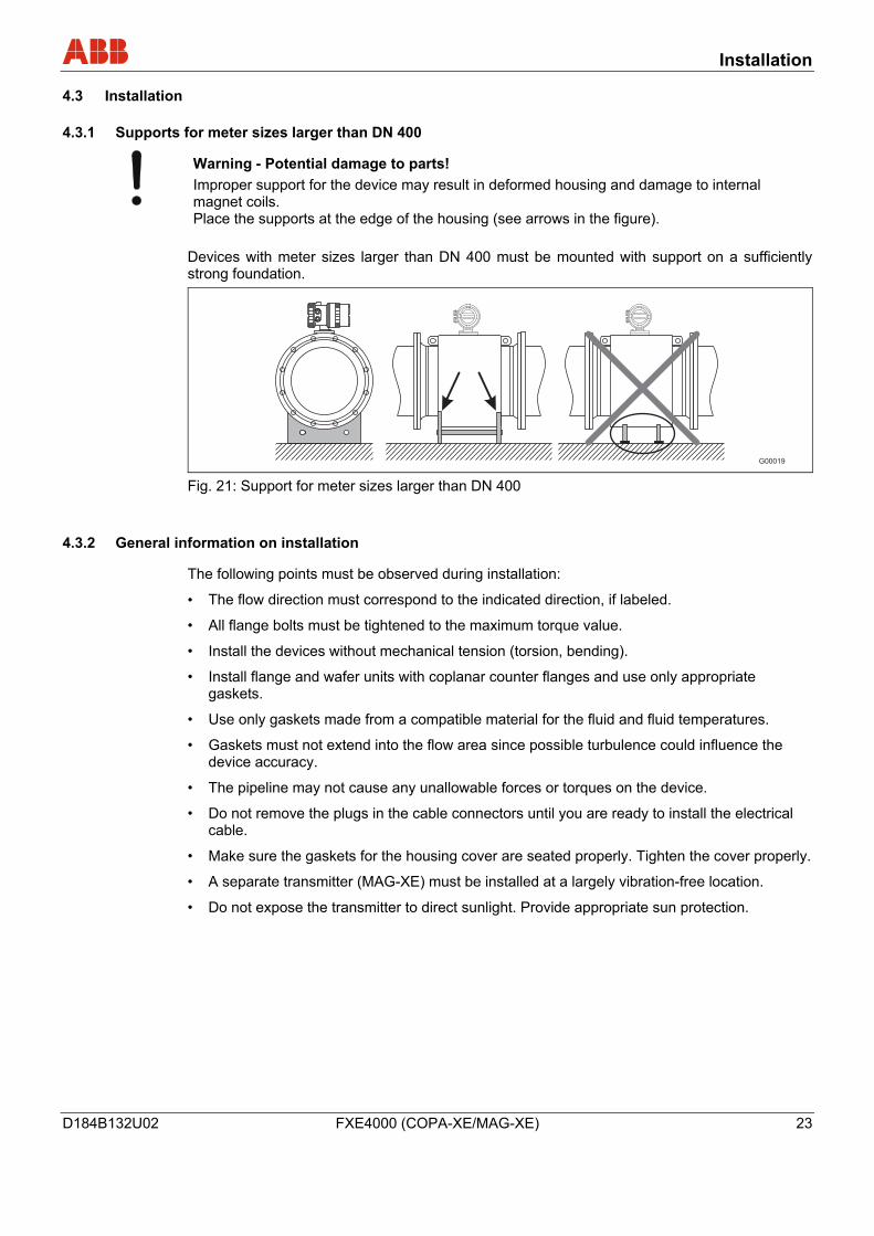
4.3.1 Supports for meter sizes larger than DN 400
Warning - Potential damage to parts! Improper support for the device may result in deformed housing and damage to internal magnet coils. Place the supports at the edge of the housing (see arrows in the figure).
Devices with meter sizes larger than DN 400 must be mounted with support on a sufficiently strong foundation.
G00019 Fig. 21: Support for meter sizes larger than DN 400
4.3.2 General information on installation
The following points must be observed during installation:
• The flow direction must correspond to the indicated direction, if labeled.
• All flange bolts must be tightened to the maximum torque value.
• Install the devices without mechanical tension (torsion, bending).
• Install flange and wafer units with coplanar counter flanges and use only appropriate gaskets.
• Use only gaskets made from a compatible material for the fluid and fluid temperatures.
• Gaskets must not extend into the flow area since possible turbulence could influence the device accuracy.
• The pipeline may not cause any unallowable forces or torques on the device.
• Do not remove the plugs in the cable connectors until you are ready to install the electrical cable.
• Make sure the gaskets for the housing cover are seated properly. Tighten the cover properly.
• A separate transmitter (MAG-XE) must be installed at a largely vibration-free location.
• Do not expose the transmitter to direct sunlight. Provide appropriate sun protection.
Installation
24 FXE4000 (COPA-XE/MAG-XE) D184B132U02
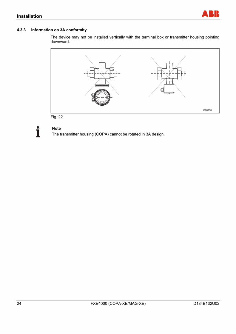
4.3.3 Information on 3A conformity
The device may not be installed vertically with the terminal box or transmitter housing pointing downward.
G00158 Fig. 22
Note The transmitter housing (COPA) cannot be rotated in 3A design.
Installation
D184B132U02 FXE4000 (COPA-XE/MAG-XE) 25
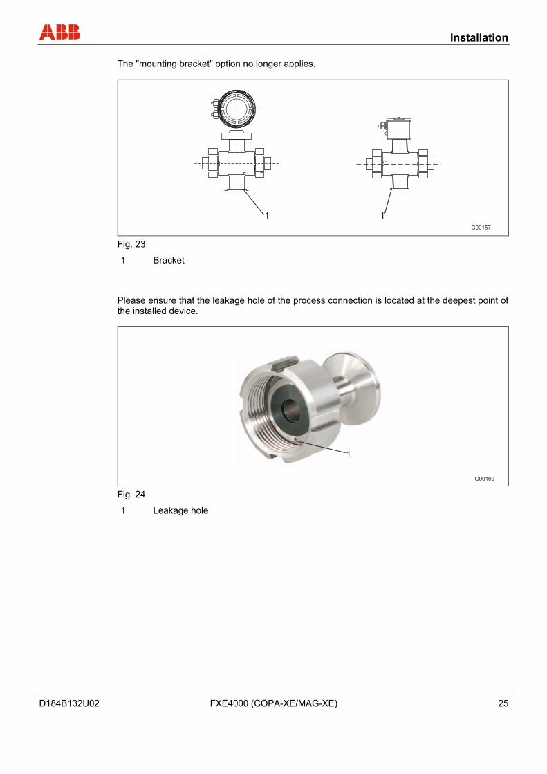
The "mounting bracket" option no longer applies.
G00157
1 1
Fig. 23
1 Bracket
Please ensure that the leakage hole of the process connection is located at the deepest point of the installed device.
1
G00169 Fig. 24
1 Leakage hole
Installation
26 FXE4000 (COPA-XE/MAG-XE) D184B132U02
F
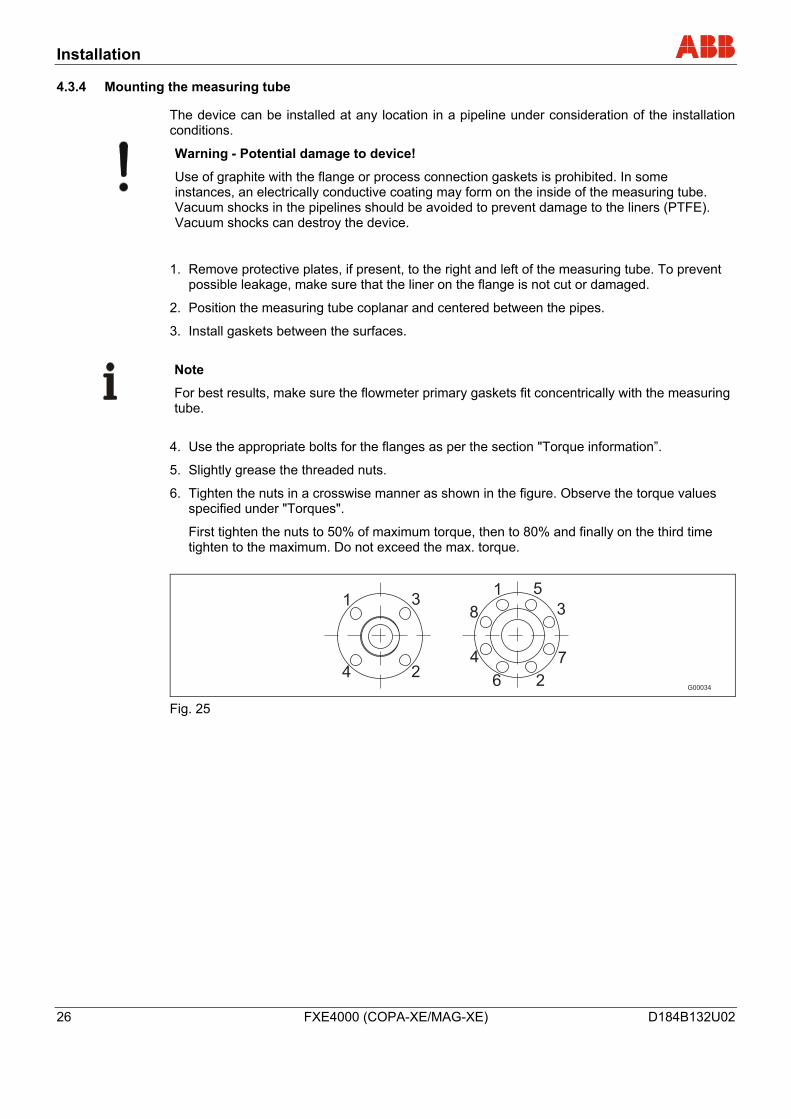
4.3.4 Mounting the measuring tube
The device can be installed at any location in a pipeline under consideration of the installation conditions.
Warning - Potential damage to device!
Use of graphite with the flange or process connection gaskets is prohibited. In some instances, an electrically conductive coating may form on the inside of the measuring tube. Vacuum shocks in the pipelines should be avoided to prevent damage to the liners (PTFE). Vacuum shocks can destroy the device.
1. Remove protective plates, if present, to the right and left of the measuring tube. To prevent possible leakage, make sure that the liner on the flange is not cut or damaged.
2. Position the measuring tube coplanar and centered between the pipes.
3. Install gaskets between the surfaces.
Note
For best results, make sure the flowmeter primary gaskets fit concentrically with the measuring tube.
4. Use the appropriate bolts for the flanges as per the section "Torque information”.
5. Slightly grease the threaded nuts.
6. Tighten the nuts in a crosswise manner as shown in the figure. Observe the torque values specified under "Torques".
First tighten the nuts to 50% of maximum torque, then to 80% and finally on the third time tighten to the maximum. Do not exceed the max. torque.
G00034
1
2
7
8
5
3
4
6
1
2
3
4
Fig. 25
Installation
D184B132U02 FXE4000 (COPA-XE/MAG-XE) 27
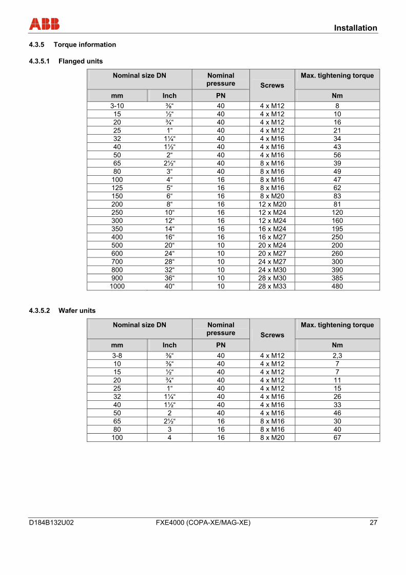
4.3.5 Torque information
4.3.5.1 Flanged units
Nominal size DN Nominal pressure
Max. tightening torque
mm Inch PN Screws
Nm 3-10 ⅜“ 40 4 x M12 8 15 ½“ 40 4 x M12 10 20 ¾“ 40 4 x M12 16 25 1“ 40 4 x M12 21 32 1¼“ 40 4 x M16 34 40 1½“ 40 4 x M16 43 50 2“ 40 4 x M16 56 65 2½“ 40 8 x M16 39 80 3“ 40 8 x M16 49
100 4“ 16 8 x M16 47 125 5“ 16 8 x M16 62 150 6“ 16 8 x M20 83 200 8“ 16 12 x M20 81 250 10“ 16 12 x M24 120 300 12“ 16 12 x M24 160 350 14“ 16 16 x M24 195 400 16“ 16 16 x M27 250 500 20“ 10 20 x M24 200 600 24“ 10 20 x M27 260 700 28“ 10 24 x M27 300 800 32“ 10 24 x M30 390 900 36“ 10 28 x M30 385 1000 40“ 10 28 x M33 480
4.3.5.2 Wafer units
Nominal size DN Nominal pressure
Max. tightening torque
mm Inch PN Screws
Nm 3-8 ⅜“ 40 4 x M12 2,3 10 ⅜“ 40 4 x M12 7 15 ½“ 40 4 x M12 7 20 ¾“ 40 4 x M12 11 25 1“ 40 4 x M12 15 32 1¼“ 40 4 x M16 26 40 1½“ 40 4 x M16 33 50 2 40 4 x M16 46 65 2½“ 16 8 x M16 30 80 3 16 8 x M16 40
100 4 16 8 x M20 67
Installation
28 FXE4000 (COPA-XE/MAG-XE) D184B132U02
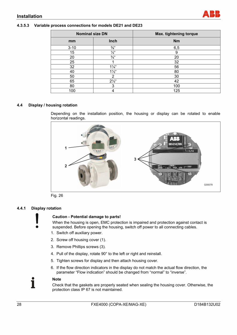
4.3.5.3 Variable process connections for models DE21 and DE23
Nominal size DN Max. tightening torque
mm Inch Nm
3-10 ⅜“ 6,5 15 ½“ 9 20 ¾“ 20 25 1 32 32 1¼“ 56 40 1½“ 80 50 2 30 65 2½“ 42 80 3 100
100 4 125
4.4 Display / housing rotation
Depending on the installation position, the housing or display can be rotated to enable horizontal readings.
G00078
3
1
2
Fig. 26
4.4.1 Display rotation
Caution - Potential damage to parts! When the housing is open, EMC protection is impaired and protection against contact is suspended. Before opening the housing, switch off power to all connecting cables.
1. Switch off auxiliary power.
2. Screw off housing cover (1).
3. Remove Phillips screws (3).
4. Pull of the display, rotate 90° to the left or right and reinstall.
5. Tighten screws for display and then attach housing cover.
6. If the flow direction indicators in the display do not match the actual flow direction, the parameter “Flow indication” should be changed from “normal” to “inverse”.
Note Check that the gaskets are properly seated when sealing the housing cover. Otherwise, the protection class IP 67 is not maintained.
Installation
D184B132U02 FXE4000 (COPA-XE/MAG-XE) 29
4.4.2 Housing rotation
1. The transmitter housing can be rotated to the left by 90° after loosening both screws (2).
2. Tighten the screws again.
4.5 Ground
4.5.1 General information on ground connections
Observe the following items when grounding the device:
• Use the supplied green/yellow cable as a ground wire.
• Connect the ground screw for the flowmeter primary (on flange and transmitter housing) to the ground.
• The terminal box or COPA housing must also be grounded.
• For plastic pipes or pipes with insulating lining, the ground is provided by the grounding plate or grounding electrodes.
• When stray currents are present in the pipeline, install a grounding plate at the front and back of the flowmeter primary.
• For measurement-related reasons, the potentials in the ground and in the pipeline should be identical.
• An additional ground via the terminals is not required.
Note If the flowmeter primary is installed in plastic pipeline, or in pipelines with an insulating lining, transient current may flow through the grounding electrode in special cases. In the long term, this may destroy the flowmeter primary, since the ground electrode will in turn degrade electrochemically. In these special cases, the connection to the ground must be performed using grounding plates.
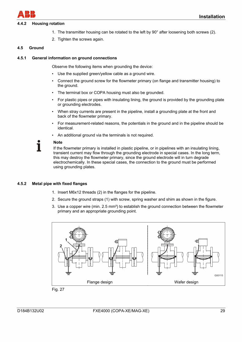
4.5.2 Metal pipe with fixed flanges
1. Insert M6x12 threads (2) in the flanges for the pipeline.
2. Secure the ground straps (1) with screw, spring washer and shim as shown in the figure.
3. Use a copper wire (min. 2.5 mm²) to establish the ground connection between the flowmeter primary and an appropriate grounding point.
G00115
1
2
Flange design Wafer design
Fig. 27
Installation
30 FXE4000 (COPA-XE/MAG-XE) D184B132U02
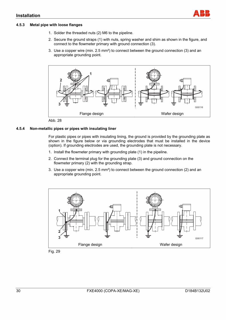
4.5.3 Metal pipe with loose flanges
1. Solder the threaded nuts (2) M6 to the pipeline.
2. Secure the ground straps (1) with nuts, spring washer and shim as shown in the figure, and connect to the flowmeter primary with ground connection (3).
3. Use a copper wire (min. 2.5 mm²) to connect between the ground connection (3) and an appropriate grounding point.
G00116
1
2
3
Flange design Wafer design
Abb. 28
4.5.4 Non-metallic pipes or pipes with insulating liner
For plastic pipes or pipes with insulating lining, the ground is provided by the grounding plate as shown in the figure below or via grounding electrodes that must be installed in the device (option). If grounding electrodes are used, the grounding plate is not necessary.
1. Install the flowmeter primary with grounding plate (1) in the pipeline.
2. Connect the terminal plug for the grounding plate (3) and ground connection on the flowmeter primary (2) with the grounding strap.
3. Use a copper wire (min. 2.5 mm²) to connect between the ground connection (2) and an appropriate grounding point.
G00117
1
2
3 Flange design Wafer design
Fig. 29
Installation
D184B132U02 FXE4000 (COPA-XE/MAG-XE) 31
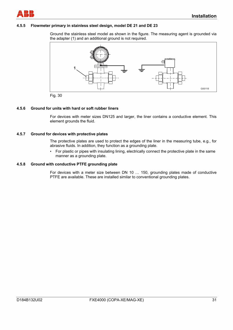
4.5.5 Flowmeter primary in stainless steel design, model DE 21 and DE 23
Ground the stainless steel model as shown in the figure. The measuring agent is grounded via the adapter (1) and an additional ground is not required.
G00118
1
Fig. 30
4.5.6 Ground for units with hard or soft rubber liners
For devices with meter sizes DN125 and larger, the liner contains a conductive element. This element grounds the fluid.
4.5.7 Ground for devices with protective plates
The protective plates are used to protect the edges of the liner in the measuring tube, e.g., for abrasive fluids. In addition, they function as a grounding plate. • For plastic or pipes with insulating lining, electrically connect the protective plate in the same
manner as a grounding plate.
4.5.8 Ground with conductive PTFE grounding plate
For devices with a meter size between DN 10 … 150, grounding plates made of conductive PTFE are available. These are installed similar to conventional grounding plates.
Installation
32 FXE4000 (COPA-XE/MAG-XE) D184B132U02
4.6 Electrical connection
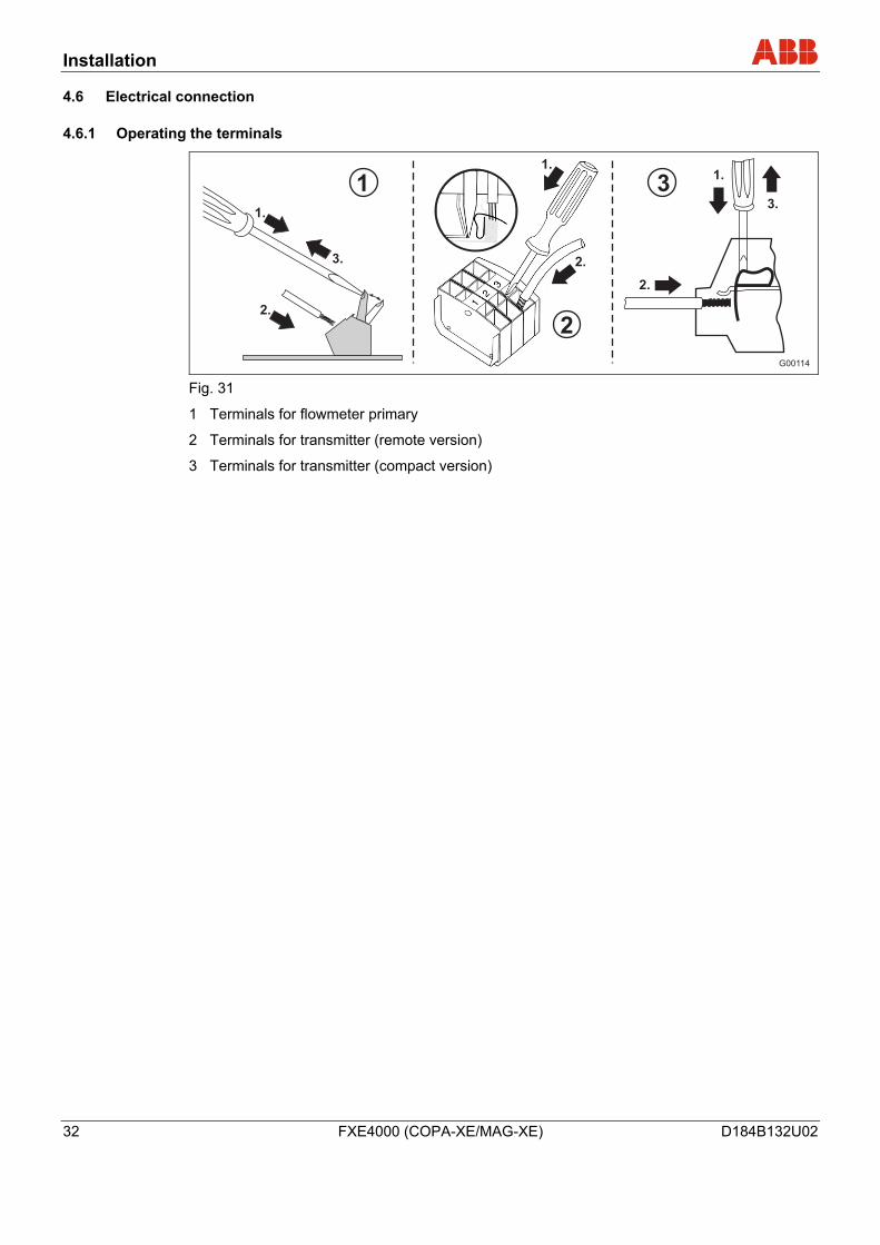
4.6.1 Operating the terminals
G00114
1
2
31.
1.
1.3.
3.
2.
2.
2.
Fig. 31
1 Terminals for flowmeter primary
2 Terminals for transmitter (remote version)
3 Terminals for transmitter (compact version)
Installation
D184B132U02 FXE4000 (COPA-XE/MAG-XE) 33
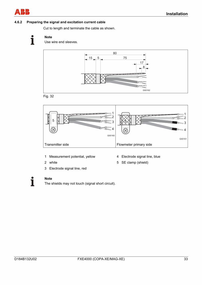
4.6.2 Preparing the signal and excitation current cable
Cut to length and terminate the cable as shown.
Note Use wire end sleeves.
Fig. 32
Transmitter side Flowmeter primary side
1 Measurement potential, yellow
2 white
3 Electrode signal line, red
4 Electrode signal line, blue
5 SE clamp (shield)
Note The shields may not touch (signal short circuit).
Installation
34 FXE4000 (COPA-XE/MAG-XE) D184B132U02
Observe the following items when routing cables:
• The signal and excitation current cable carries a voltage signal of only a few millivolts and therefore must be routed the shortest distance possible. The maximum permissible signal cable length is 50 m.
• Avoid routing the cable in the vicinity of electrical equipment or switching elements that can create stray fields, switching pulses and induction. If this is not possible, run the signal/excitation current cable through a metal pipe and connect this to the ground.
• All leads must be shielded and connected to station ground.
• Do not run the signal cable over junction boxes or terminal blocks. A shielded excitation cable (white) is run parallel to the signal lines (red and blue). As a result, only one cable is required between the flowmeter primary and the transmitter.
• To shield against magnetic interspersion, the cable contains outer shielding that is attached to the SE clamp.
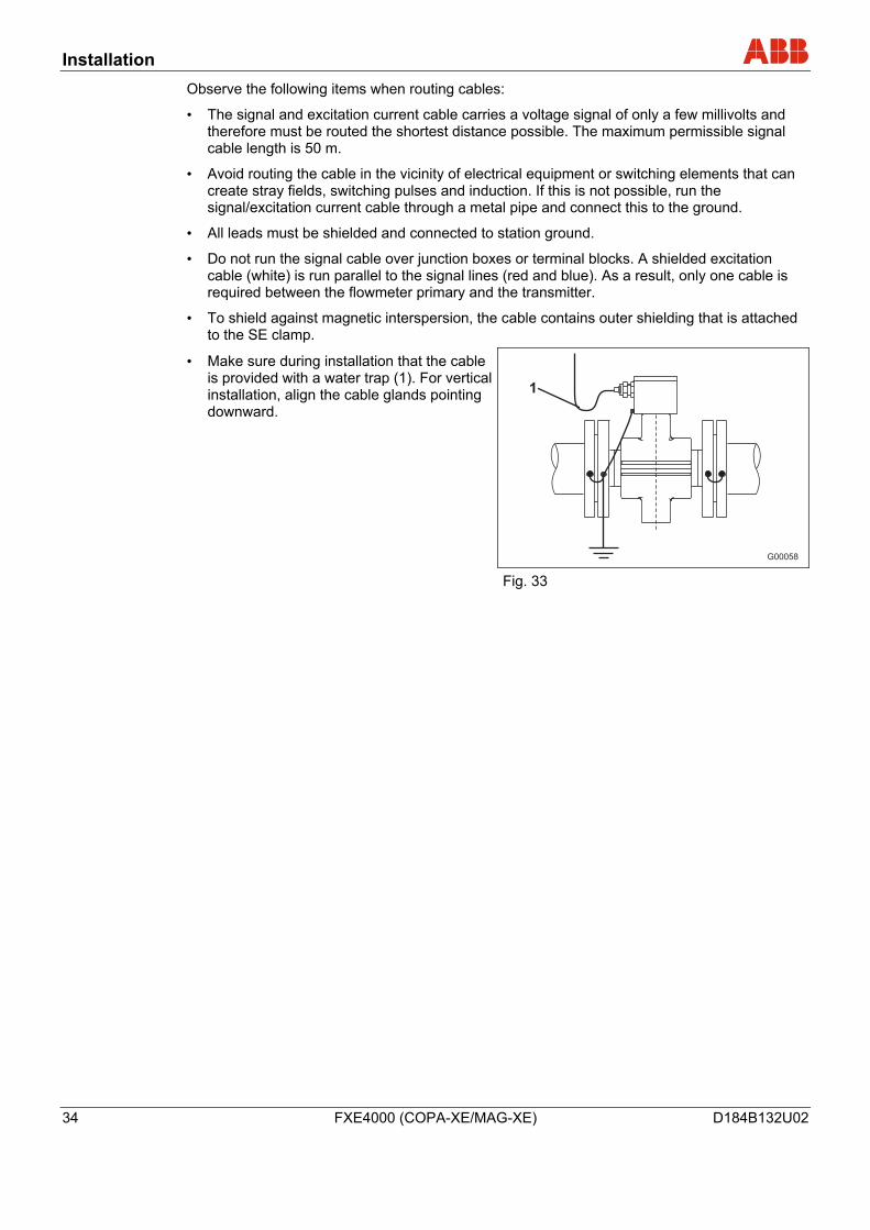
• Make sure during installation that the cable is provided with a water trap (1). For vertical installation, align the cable glands pointing downward.
Fig. 33
Installation
D184B132U02 FXE4000 (COPA-XE/MAG-XE) 35
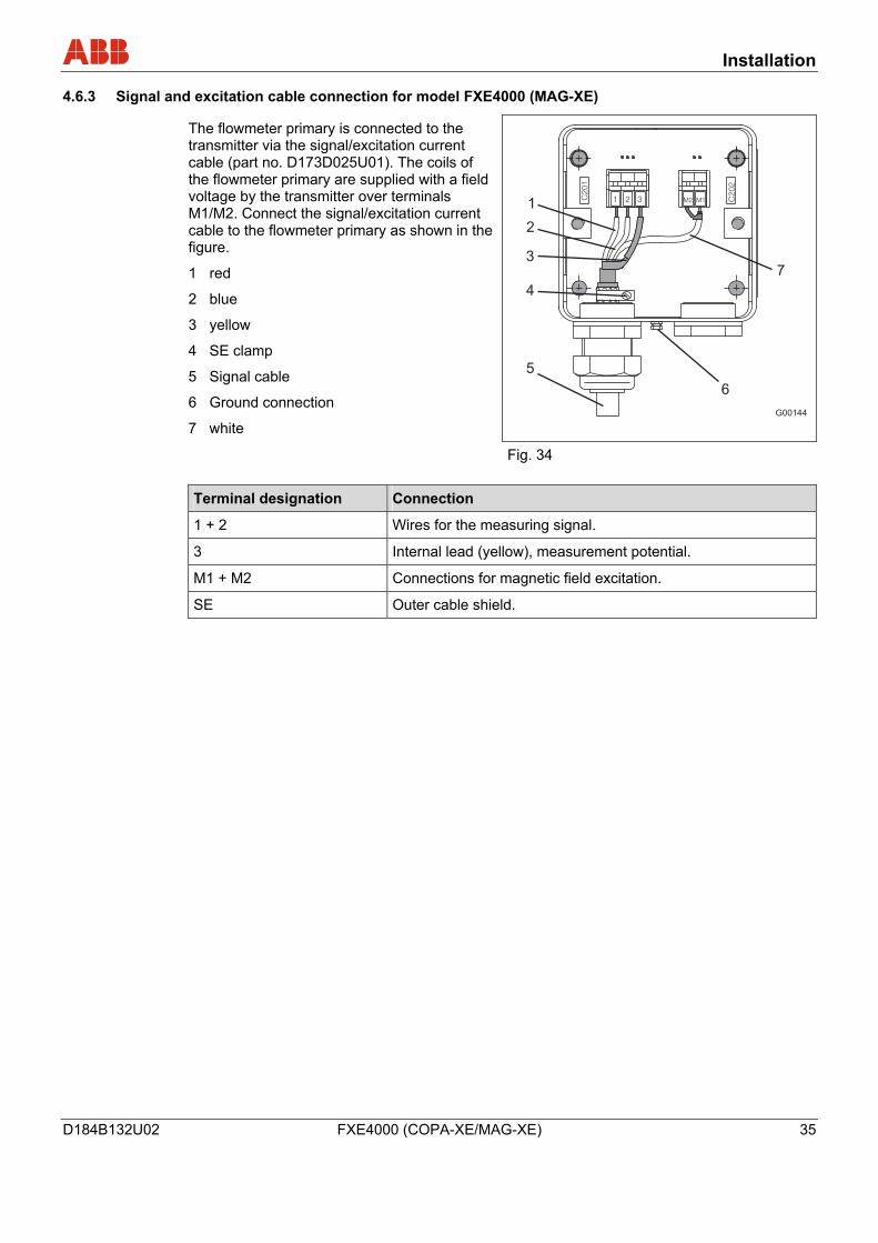
4.6.3 Signal and excitation cable connection for model FXE4000 (MAG-XE)
The flowmeter primary is connected to the transmitter via the signal/excitation current cable (part no. D173D025U01). The coils of the flowmeter primary are supplied with a field voltage by the transmitter over terminals M1/M2. Connect the signal/excitation current cable to the flowmeter primary as shown in the figure.
1 red
2 blue
3 yellow
4 SE clamp
5 Signal cable
6 Ground connection
7 white
Fig. 34 Terminal designation Connection
1 + 2 Wires for the measuring signal.
3 Internal lead (yellow), measurement potential.
M1 + M2 Connections for magnetic field excitation.
SE Outer cable shield.
Installation
36 FXE4000 (COPA-XE/MAG-XE) D184B132U02
4.6.4 Connection for protection class IP68
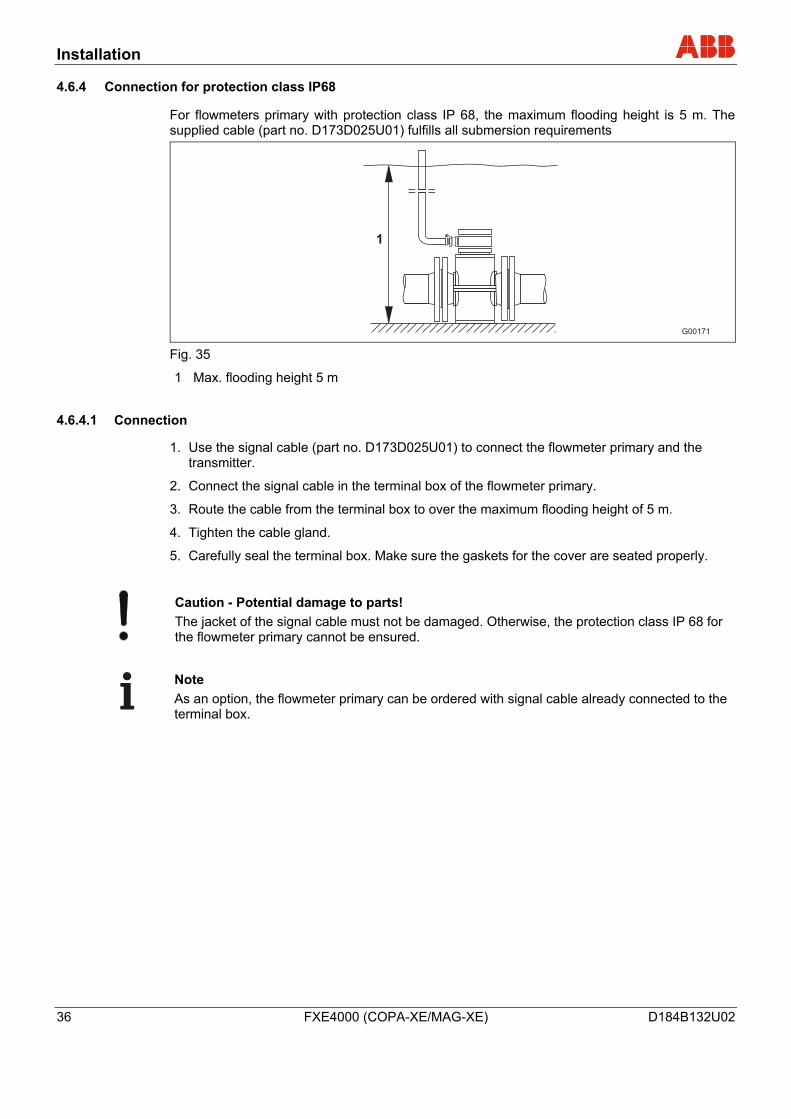
For flowmeters primary with protection class IP 68, the maximum flooding height is 5 m. The supplied cable (part no. D173D025U01) fulfills all submersion requirements
Fig. 35
1 Max. flooding height 5 m
4.6.4.1 Connection
1. Use the signal cable (part no. D173D025U01) to connect the flowmeter primary and the transmitter.
2. Connect the signal cable in the terminal box of the flowmeter primary.
3. Route the cable from the terminal box to over the maximum flooding height of 5 m.
4. Tighten the cable gland.
5. Carefully seal the terminal box. Make sure the gaskets for the cover are seated properly.
Caution - Potential damage to parts! The jacket of the signal cable must not be damaged. Otherwise, the protection class IP 68 for the flowmeter primary cannot be ensured.
Note As an option, the flowmeter primary can be ordered with signal cable already connected to the terminal box.
Installation
D184B132U02 FXE4000 (COPA-XE/MAG-XE) 37
4.6.4.2 Potting the connection box
If the terminal box is to be potted on-site, a special potting compound can be ordered separately (order no. D141B038U01). Potting is only possible if the flowmeter primary is installed horizontally. Observe the following instructions during work activity:
Warning - General hazards! The sealing compound is toxic. Observe all relevant safety measures. Risk notes: R20, R36/37/38, R42/43 Harmful by inhalation. Avoid direct skin contact. Irritating to eyes. Safety advice: P4, S23-A, S24/25, S26, S37, S38 Wear suitable protective gloves and ensure sufficient ventilation. Follow the instructions that are provided by the manufacturer prior to starting any preparations.
Preparation
• Complete the installation before beginning sealing activities in order avoid moisture penetration. Before starting, check all the connections for correct fitting and stability.
• Do not overfill the terminal box. Keep the potting compound away from the O-ring and the seal/groove (see below).
• Prevent the potting compound from penetrating a conduit if an NPT ½” thread is used.
Installation
38 FXE4000 (COPA-XE/MAG-XE) D184B132U02
Procedure
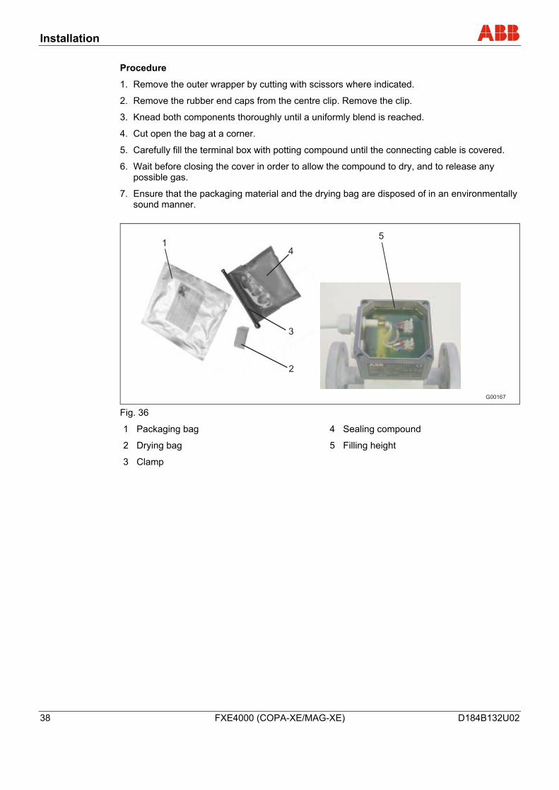
1. Remove the outer wrapper by cutting with scissors where indicated.
2. Remove the rubber end caps from the centre clip. Remove the clip.
3. Knead both components thoroughly until a uniformly blend is reached.
4. Cut open the bag at a corner.
5. Carefully fill the terminal box with potting compound until the connecting cable is covered.
6. Wait before closing the cover in order to allow the compound to dry, and to release any possible gas.
7. Ensure that the packaging material and the drying bag are disposed of in an environmentally sound manner.
G00167
1
2
3
4
5
Fig. 36
1 Packaging bag
2 Drying bag
3 Clamp
4 Sealing compound
5 Filling height
Installation
D184B132U02 FXE4000 (COPA-XE/MAG-XE) 39
4.6.5 Interconnection Diagrams
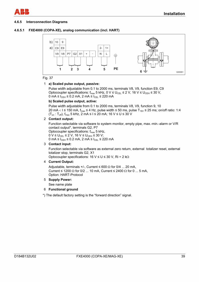
4.6.5.1 FXE4000 (COPA-XE), analog communication (incl. HART)
G00061
10
C9
V9 V8 P7 G2 X1 + -
9
2-
N
1+
L
PE1
b)
a)
2 3 4 56
E9
Fig. 37
1 a) Scaled pulse output, passive: Pulse width adjustable from 0.1 to 2000 ms, terminals V8, V9, function E9, C9 Optocoupler specifications: fmax 5 kHz, 0 V ≤ UCEL ≤ 2 V, 16 V ≤ UCEH ≤ 30 V, 0 mA ≤ ICEH ≤ 0.2 mA, 2 mA ≤ ICEL ≤ 220 mA
b) Scaled pulse output, active: Pulse width adjustable from 0.1 to 2000 ms, terminals V8, V9, function 9, 10 20 mA < I ≤ 150 mA, fmax ≤ 4 Hz, pulse width ≤ 50 ms, pulse T16V ≤ 25 ms; on/off ratio: 1:4 (Ton : Toff), fmax 5 kHz, 2 mA ≤ I ≤ 20 mA; 16 V ≤ U ≤ 30 V
2 Contact output: Function selectable via software to system monitor, empty pipe, max.-min.-alarm or V/R contact output*, terminals G2, P7 Optocoupler specifications: fmax 5 kHz, 0 V ≤ UCEL ≤ 2 V, 16 V ≤ UCEH ≤ 30 V; 0 mA ≤ ICEH ≤ 0.2 mA, 2 mA ≤ ICEL ≤ 220 mA
3 Contact input: Function selectable via software as external zero return, external totalizer reset, external totalizer stop, terminals G2, X1 Optocoupler specifications: 16 V ≤ U ≤ 30 V, Ri = 2 kΩ
4 Current Output: Adjustable, terminals +/-, Current ≤ 600 Ω for 0/4 ... 20 mA, Current ≤ 1200 Ω for 0/2 ... 10 mA, Current ≤ 2400 Ω for 0 ... 5 mA, Option: HART-Protocol
5 Supply Power: See name plate
6 Functional ground
*) The default factory setting is the “forward direction” signal.
Installation
40 FXE4000 (COPA-XE/MAG-XE) D184B132U02
4.6.5.2 FXE4000 (COPA-XE), digital communication
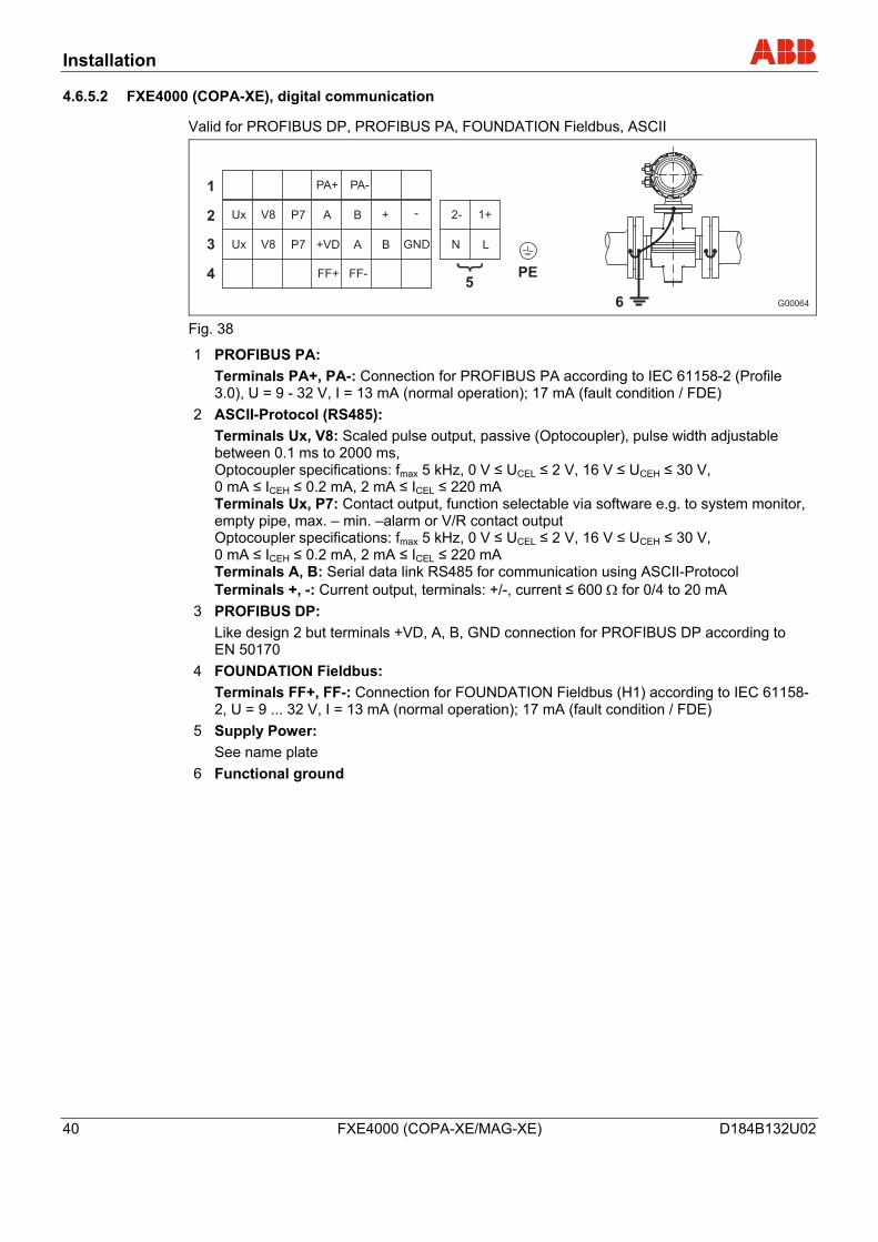
Valid for PROFIBUS DP, PROFIBUS PA, FOUNDATION Fieldbus, ASCII
G00064
Ux
Ux
1
2
3
45
V8
V8
P7
P7
+VD
FF+
PA+
A
PA-
B
A
FF-
+
B
-
GND N L
PE
1+2-
6
Fig. 38
1 PROFIBUS PA: Terminals PA+, PA-: Connection for PROFIBUS PA according to IEC 61158-2 (Profile 3.0), U = 9 - 32 V, I = 13 mA (normal operation); 17 mA (fault condition / FDE)
2 ASCII-Protocol (RS485): Terminals Ux, V8: Scaled pulse output, passive (Optocoupler), pulse width adjustable between 0.1 ms to 2000 ms, Optocoupler specifications: fmax 5 kHz, 0 V ≤ UCEL ≤ 2 V, 16 V ≤ UCEH ≤ 30 V, 0 mA ≤ ICEH ≤ 0.2 mA, 2 mA ≤ ICEL ≤ 220 mA Terminals Ux, P7: Contact output, function selectable via software e.g. to system monitor, empty pipe, max. – min. –alarm or V/R contact output Optocoupler specifications: fmax 5 kHz, 0 V ≤ UCEL ≤ 2 V, 16 V ≤ UCEH ≤ 30 V, 0 mA ≤ ICEH ≤ 0.2 mA, 2 mA ≤ ICEL ≤ 220 mA Terminals A, B: Serial data link RS485 for communication using ASCII-Protocol Terminals +, -: Current output, terminals: +/-, current ≤ 600 Ω for 0/4 to 20 mA
3 PROFIBUS DP: Like design 2 but terminals +VD, A, B, GND connection for PROFIBUS DP according to EN 50170
4 FOUNDATION Fieldbus: Terminals FF+, FF-: Connection for FOUNDATION Fieldbus (H1) according to IEC 61158-2, U = 9 ... 32 V, I = 13 mA (normal operation); 17 mA (fault condition / FDE)
5 Supply Power: See name plate
6 Functional ground
Installation
D184B132U02 FXE4000 (COPA-XE/MAG-XE) 41
4.6.5.3 FXE4000 MAG-XE, analog communication (incl. HART)
G00065
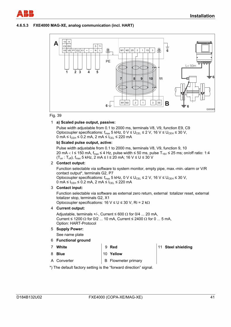
Fig. 39
1 a) Scaled pulse output, passive: Pulse width adjustable from 0.1 to 2000 ms, terminals V8, V9, function E9, C9 Optocoupler specifications: fmax 5 kHz, 0 V ≤ UCEL ≤ 2 V, 16 V ≤ UCEH ≤ 30 V, 0 mA ≤ ICEH ≤ 0.2 mA, 2 mA ≤ ICEL ≤ 220 mA
b) Scaled pulse output, active: Pulse width adjustable from 0.1 to 2000 ms, terminals V8, V9, function 9, 10 20 mA < I ≤ 150 mA, fmax ≤ 4 Hz, pulse width ≤ 50 ms, pulse T16V ≤ 25 ms; on/off ratio: 1:4 (Ton : Toff), fmax 5 kHz, 2 mA ≤ I ≤ 20 mA; 16 V ≤ U ≤ 30 V
2 Contact output: Function selectable via software to system monitor, empty pipe, max.-min.-alarm or V/R contact output*, terminals G2, P7 Optocoupler specifications: fmax 5 kHz, 0 V ≤ UCEL ≤ 2 V, 16 V ≤ UCEH ≤ 30 V, 0 mA ≤ ICEH ≤ 0.2 mA, 2 mA ≤ ICEL ≤ 220 mA
3 Contact input: Function selectable via software as external zero return, external totalizer reset, external totalizer stop, terminals G2, X1 Optocoupler specifications: 16 V ≤ U ≤ 30 V, Ri = 2 kΩ
4 Current output: Adjustable, terminals +/-, Current ≤ 600 Ω for 0/4 ... 20 mA, Current ≤ 1200 Ω for 0/2 ... 10 mA, Current ≤ 2400 Ω for 0 ... 5 mA, Option: HART-Protocol
5 Supply Power: See name plate
6 Functional ground
7
8
A
White
Blue
Converter
9
10
B
Red
Yellow
Flowmeter primary
11
Steel shielding
*) The default factory setting is the “forward direction” signal.
Installation
42 FXE4000 (COPA-XE/MAG-XE) D184B132U02
4.6.5.4 FXE4000 (MAG-XE), digital communication
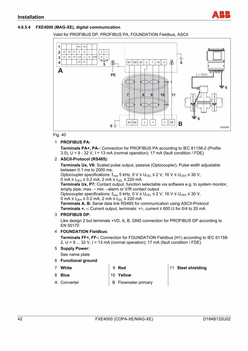
Valid for PROFIBUS DP, PROFIBUS PA, FOUNDATION Fieldbus, ASCII
G00066
M1
A
Ux
Ux
V8
V8
P7
P7
+VD
FF+
PA+
A
PA-
B
A
FF-
+
B
-
GND N L
1+2-
M2 2 1 3 SE
PE
6
7 8 9 10 11
6
6
6
M1 M2 22S 1S1 3
B
1
2
3
45
Fig. 40
1 PROFIBUS PA: Terminals PA+, PA-: Connection for PROFIBUS PA according to IEC 61158-2 (Profile 3.0), U = 9 - 32 V, I = 13 mA (normal operation); 17 mA (fault condition / FDE)
2 ASCII-Protocol (RS485): Terminals Ux, V8: Scaled pulse output, passive (Optocoupler), Pulse width adjustable between 0.1 ms to 2000 ms, Optocoupler specifications: fmax 5 kHz, 0 V ≤ UCEL ≤ 2 V, 16 V ≤ UCEH ≤ 30 V, 0 mA ≤ ICEH ≤ 0.2 mA, 2 mA ≤ ICEL ≤ 220 mA Terminals Ux, P7: Contact output, function selectable via software e.g. to system monitor, empty pipe, max. – min. –alarm or V/R contact output Optocoupler specifications: fmax 5 kHz, 0 V ≤ UCEL ≤ 2 V, 16 V ≤ UCEH ≤ 30 V, 0 mA ≤ ICEH ≤ 0.2 mA, 2 mA ≤ ICEL ≤ 220 mA Terminals A, B: Serial data link RS485 for communication using ASCII-Protocol Terminals +, -: Current output, terminals: +/-, current ≤ 600 Ω for 0/4 to 20 mA
3 PROFIBUS DP: Like design 2 but terminals +VD, A, B, GND connection for PROFIBUS DP according to EN 50170
4 FOUNDATION Fieldbus: Terminals FF+, FF-: Connection for FOUNDATION Fieldbus (H1) according to IEC 61158-2, U = 9 ... 32 V, I = 13 mA (normal operation); 17 mA (fault condition / FDE)
5 Supply Power: See name plate
6 Functional ground
7
8
A
White
Blue
Converter
9
10
B
Red
Yellow
Flowmeter primary
11
Steel shielding
Installation
D184B132U02 FXE4000 (COPA-XE/MAG-XE) 43
4.6.5.5 Interconnection examples for the peripherals with analog communication (incl. HART)
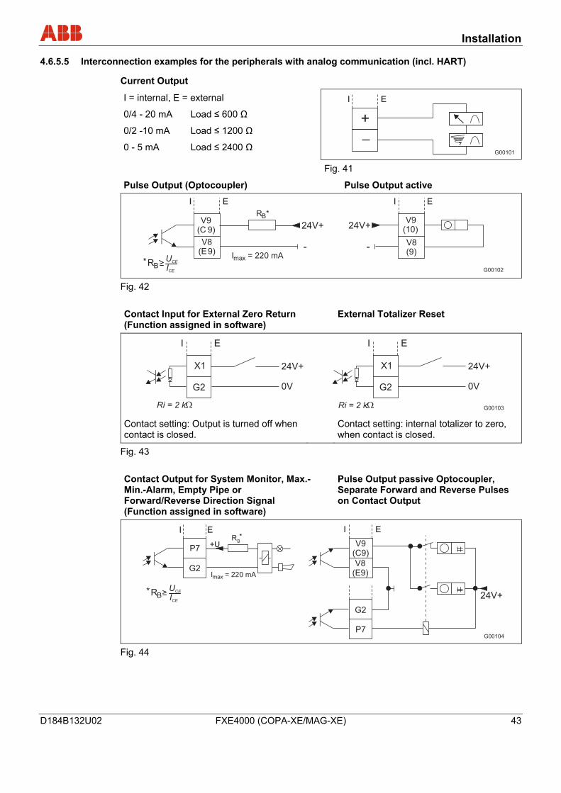
Current Output
I = internal, E = external
0/4 - 20 mA Load ≤ 600 Ω
0/2 -10 mA Load ≤ 1200 Ω
0 - 5 mA Load ≤ 2400 Ω G00101
I E
Fig. 41
Pulse Output (Optocoupler) Pulse Output active
G00102
(E
(C
RB*
Imax = 220 mA
24V+
-V8
9)
V99)
(9)
(10)24V+
- V8
V9
RB* U
CE
ICE
I IE E
Fig. 42 Contact Input for External Zero Return (Function assigned in software)
External Totalizer Reset
G00103
24V+ 24V+
0V 0VG2 G2
X1 X1
Ri = 2 kRi = 2 k
II EE
Contact setting: Output is turned off when contact is closed.
Contact setting: internal totalizer to zero, when contact is closed.
Fig. 43 Contact Output for System Monitor, Max.-Min.-Alarm, Empty Pipe or Forward/Reverse Direction Signal (Function assigned in software)
Pulse Output passive Optocoupler, Separate Forward and Reverse Pulses on Contact Output
G00104
RB*
Imax = 220 mAG2
G2
V9(C9)
P7
P7
V8(E9)
RB* U
CE
ICE
+U
24V+
II EE
Fig. 44
Installation
44 FXE4000 (COPA-XE/MAG-XE) D184B132U02
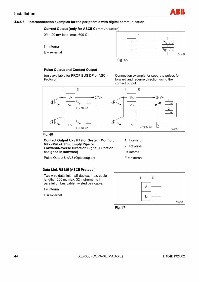
4.6.5.6 Interconnection examples for the peripherals with digital communication
Current Output (only for ASCII-Communication)
0/4 - 20 mA load: max. 600 Ω
I = internal
E = external G00101
I E
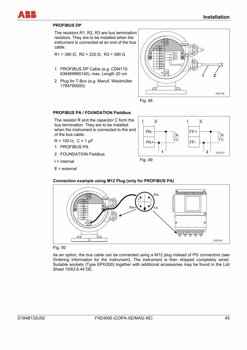
Fig. 45 Pulse Output and Contact Output
(only available for PROFIBUS DP or ASCII-Protocol)
Connection example for separate pulses for forward and reverse direction using the contact output
G00105
Imax
I = 220 mAmax
R
Ux
P7
V8
Imax
I = 220 mAmax
R
24V+ Ux
P7
V8
I = 220 mAmax
24V+1
2
II EE
Fig. 46
Contact Output Ux / P7 (for System Monitor, Max.-Min.-Alarm, Empty Pipe or Forward/Reverse Direction Signal ,Function assigned in software)
Pulse Output Ux/V8 (Optocoupler)
1 Forward
2 Reverse
I = internal
E = external
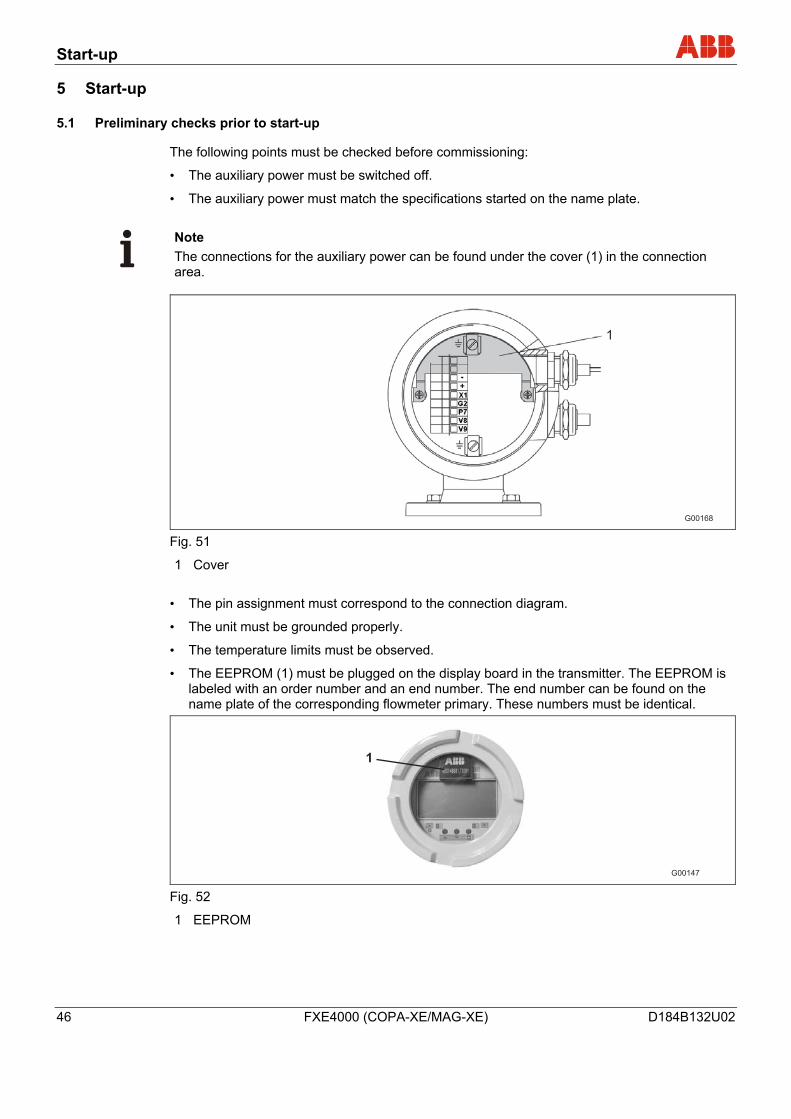
Data Link RS485 (ASCII Protocol)
G00108
B
A
I ETwo wire data link, half-duplex, max. cable length: 1200 m, max. 32 instruments in parallel on bus cable, twisted pair cable.
I = internal
E = external
Fig. 47
Installation
D184B132U02 FXE4000 (COPA-XE/MAG-XE) 45
PROFIBUS DP
The resistors R1, R2, R3 are bus termination resistors. They are to be installed when the instrument is connected at an end of the bus cable.
R1 = 390 Ω; R2 = 220 Ω; R3 = 390 Ω
1 PROFIBUS DP Cable (e.g. CDN110: 636469890140), max. Length 20 cm
2 Plug for T-Box (e.g. Manuf. Weidmüller 1784790000)
G00106
1 2
Ux
V8P7
+VD
AB
R1
R2R3
GND
Fig. 48
PROFIBUS PA / FOUNDATION Fieldbus
G001072
FF-
FF+RC
I E
1
PA+
PA-RC
I E
The resistor R and the capacitor C form the bus termination. They are to be installed when the instrument is connected to the end of the bus cable. R = 100 Ω; C = 1 µF 1 PROFIBUS PA
2 FOUNDATION Fieldbus
I = internal
E = external
Fig. 49
Connection example using M12 Plug (only for PROFIBUS PA)
G00109
4
1
3
2N
PA-
PA+
L
PA+ nc
PA-
Fig. 50
As an option, the bus cable can be connected using a M12 plug instead of PG connectors (see Ordering Information for the instrument). The instrument is then shipped completely wired. Suitable sockets (Type EPG300) together with additional accessories may be found in the List Sheet 10/63.6.44 DE.
Start-up
46 FXE4000 (COPA-XE/MAG-XE) D184B132U02
5 Start-up
5.1 Preliminary checks prior to start-up
The following points must be checked before commissioning:
• The auxiliary power must be switched off.
• The auxiliary power must match the specifications started on the name plate.
Note The connections for the auxiliary power can be found under the cover (1) in the connection area.
Fig. 51
1 Cover • The pin assignment must correspond to the connection diagram.
• The unit must be grounded properly.
• The temperature limits must be observed.
• The EEPROM (1) must be plugged on the display board in the transmitter. The EEPROM is labeled with an order number and an end number. The end number can be found on the name plate of the corresponding flowmeter primary. These numbers must be identical.
G00147
1
Fig. 52
1 EEPROM
Start-up
D184B132U02 FXE4000 (COPA-XE/MAG-XE) 47
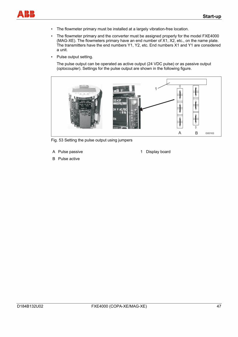
• The flowmeter primary must be installed at a largely vibration-free location.
• The flowmeter primary and the converter must be assigned properly for the model FXE4000 (MAG-XE). The flowmeters primary have an end number of X1, X2, etc., on the name plate. The transmitters have the end numbers Y1, Y2, etc. End numbers X1 and Y1 are considered a unit.
• Pulse output setting.
The pulse output can be operated as active output (24 VDC pulse) or as passive output (optocoupler). Settings for the pulse output are shown in the following figure.
A B G00163
1
Fig. 53 Setting the pulse output using jumpers A Pulse passive 1 Display board
B Pulse active
Start-up
48 FXE4000 (COPA-XE/MAG-XE) D184B132U02
5.2 Commissioning the unit
5.2.1 Switching on auxiliary power
After switching on the auxiliary power, the flowmeter data in the external EEPROM is compared with the data saved internally. If the data is not identical, the transmitter uploads data from the external EEPROM automatically. Once completed, the message “Primary data are loaded” is displayed. The measuring equipment is now ready for operation.
The display shows the current flowrate.
5.2.2 Device configuration
The parameter setting can be done prior shipment in accordance to customer specifications upon request. If no customer information is available, the device is delivered with factory settings.
On-site configuration requires only a few parameter settings. For information on settings, refer to the chapter "Parameterization". A short overview of the menu structure can be found in the section "Parameter overview".
The following parameters should be checked or set before start-up:
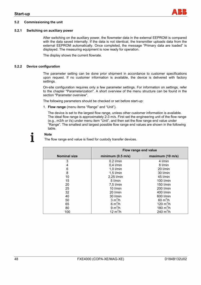
1. Flow range (menu items “Range” and “Unit”).
The device is set to the largest flow range, unless other customer information is available. The ideal flow range is approximately 2-3 m/s. First set the engineering unit of the flow range (e.g., m3/h or l/s) under menu item “Unit”, and then set the flow range end value under “Range”. The smallest and largest possible flow range end values are shown in the following table.
Note The flow range end value is fixed for custody transfer devices.
Flow range end value
Nominal size minimum (0.5 m/s) maximum (10 m/s) 3 4 6 8
10 15 20 25 32 40 50 65 80 100
0.2 l/min 0,4 l/min 1,0 l/min 1,5 l/min 2,25 l/min
5 l/min 7,5 l/min 10 l/min 20 l/min 30 l/min 3 m3/h 6 m3/h 9 m3/h
12 m3/h
4 l/min 8 l/min
20 l/min 30 l/min 45 l/min 100 l/min 150 l/min 200 l/min 400 l/min 600 l/min 60 m3/h 120 m3/h 180 m3/h 240 m3/h
Start-up
D184B132U02 FXE4000 (COPA-XE/MAG-XE) 49
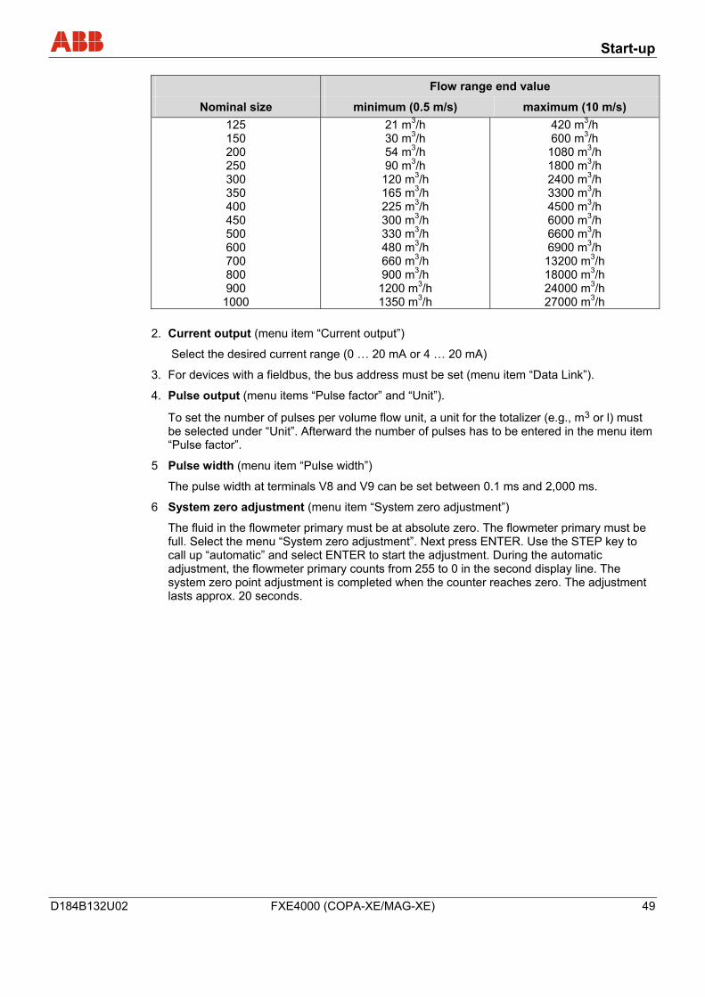
Flow range end value
Nominal size minimum (0.5 m/s) maximum (10 m/s) 125 150 200 250 300 350 400 450 500 600 700 800 900
1000
21 m3/h 30 m3/h 54 m3/h 90 m3/h 120 m3/h 165 m3/h 225 m3/h 300 m3/h 330 m3/h 480 m3/h 660 m3/h 900 m3/h
1200 m3/h 1350 m3/h
420 m3/h 600 m3/h
1080 m3/h 1800 m3/h 2400 m3/h 3300 m3/h 4500 m3/h 6000 m3/h 6600 m3/h 6900 m3/h 13200 m3/h 18000 m3/h 24000 m3/h 27000 m3/h
2. Current output (menu item “Current output”)
Select the desired current range (0 … 20 mA or 4 … 20 mA)
3. For devices with a fieldbus, the bus address must be set (menu item “Data Link”).
4. Pulse output (menu items “Pulse factor” and “Unit”).
To set the number of pulses per volume flow unit, a unit for the totalizer (e.g., m3 or l) must be selected under “Unit”. Afterward the number of pulses has to be entered in the menu item “Pulse factor”.
5 Pulse width (menu item “Pulse width”)
The pulse width at terminals V8 and V9 can be set between 0.1 ms and 2,000 ms.
6 System zero adjustment (menu item “System zero adjustment”)
The fluid in the flowmeter primary must be at absolute zero. The flowmeter primary must be full. Select the menu “System zero adjustment”. Next press ENTER. Use the STEP key to call up “automatic” and select ENTER to start the adjustment. During the automatic adjustment, the flowmeter primary counts from 255 to 0 in the second display line. The system zero point adjustment is completed when the counter reaches zero. The adjustment lasts approx. 20 seconds.
Start-up
50 FXE4000 (COPA-XE/MAG-XE) D184B132U02
7 Detector empty pipe
(menu item “Detector e. pipe”), for devices with meter size DN10 and larger
The measuring tube for the flowmeter primary must be full. Select the menu “Detector e. pipe”. Next press ENTER. Use the STEP key to call up “Adjust detector e. pipe” and select ENTER to start the adjustment. A number is displayed. Use the STEP or DATA key to change to the value 2000 ± 25 Hz. To accept this value, press ENTER.
Now empty the pipeline. The adjustment value displayed must rise above the value set in the “Threshold” menu. This ensures the empty pipe detector is adjusted.
Note
When configuration is complete, all data must be saved. To do so, call up the menu item “Save data to ext. EEPROM” and select ENTER.
5.3 Commissioning PROFIBUS PA units
For units with PROFIBUS PA, the bus address must be checked or configured prior to start-up. If no bus address information was supplied by the customer, the unit was shipped with its BUS address set to “126”. The address must be reset during start-up to a number within the valid range (0 … 125).
Note The address selected may only appear once in the segment.
The address can be set either locally on the unit (via the DIP switches on the digital board), using system tools, or via a PROFIBUS DP master class 2 such as SMART VISION. The factory setting for DIP switch 8 is OFF, i.e., the address is set using the fieldbus. The front cover can be unscrewed to change the settings. It is also possible to set the address via menu by using the keys on the display board. The PROFIBUS PA interface conforms with Profile 3.0 (fieldbus standard PROFIBUS, EN 50170, DIN 19245 [PRO91]). The converter transmission signal is designed according to IEC 61158-2.
Note The manufacturer-specific PROFIBUS PA ID no. is: 0691 hex. The unit can also be operated with the PROFIBUS standard ID nos. 9700 or 9740.
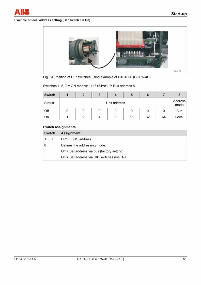
Start-up
D184B132U02 FXE4000 (COPA-XE/MAG-XE) 51
Example of local address setting (DIP switch 8 = On)
G00172 Fig. 54 Position of DIP switches using example of FXE4000 (COPA-XE) Switches 1, 5, 7 = ON means: 1+16+64=81 Bus address 81 Switch 1 2 3 4 5 6 7 8
Status Unit address Address mode
Off 0 0 0 0 0 0 0 Bus
On 1 2 4 8 16 32 64 Local Switch assignments
Switch Assignment
1 … 7 PROFIBUS address
8 Defines the addressing mode:
Off = Set address via bus (factory setting)
On = Set address via DIP switches nos. 1-7
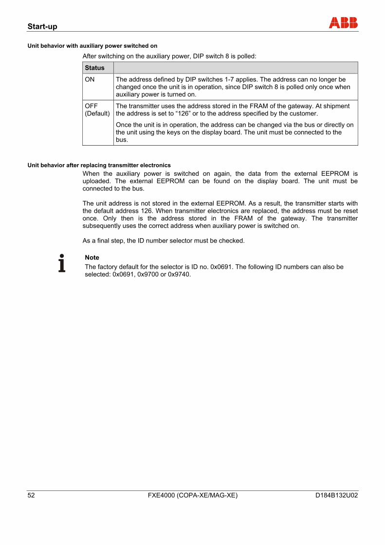
Start-up
52 FXE4000 (COPA-XE/MAG-XE) D184B132U02
Unit behavior with auxiliary power switched on
After switching on the auxiliary power, DIP switch 8 is polled:
Status
ON The address defined by DIP switches 1-7 applies. The address can no longer be changed once the unit is in operation, since DIP switch 8 is polled only once when auxiliary power is turned on.
OFF (Default)
The transmitter uses the address stored in the FRAM of the gateway. At shipment the address is set to “126” or to the address specified by the customer.
Once the unit is in operation, the address can be changed via the bus or directly on the unit using the keys on the display board. The unit must be connected to the bus.
Unit behavior after replacing transmitter electronics When the auxiliary power is switched on again, the data from the external EEPROM is uploaded. The external EEPROM can be found on the display board. The unit must be connected to the bus. The unit address is not stored in the external EEPROM. As a result, the transmitter starts with the default address 126. When transmitter electronics are replaced, the address must be reset once. Only then is the address stored in the FRAM of the gateway. The transmitter subsequently uses the correct address when auxiliary power is switched on. As a final step, the ID number selector must be checked.
Note The factory default for the selector is ID no. 0x0691. The following ID numbers can also be selected: 0x0691, 0x9700 or 0x9740.
Start-up
D184B132U02 FXE4000 (COPA-XE/MAG-XE) 53
5.3.1 Information on voltage/current consumption
The behavior when switching on the unit corresponds to Draft DIN IEC / 65C / 155 / CDV of June 1996. The average current draw of the unit is 13 mA. The voltage on the bus line must lie in the range of 9 … 32 V DC.
Note The upper limit of the voltage is electronically limited. In the event of an error, the integrated FDE function (Fault Disconnection Electronic) integrated in the device ensures that the current consumption can rise to a maximum of 17 mA.
5.3.2 System integration
Use of PROFIBUS-PA Profile B, B3.0 ensures interoperability and interchangeability of units. Interoperability means that devices from different manufacturers can be physically connected to a bus and are communication-ready. In addition, third-party devices can be interchanged without having to reconfigure the process control system. To support interchangeability, ABB provides three different GSD files that can be integrated in the system. Users decide at system integration whether to install the full range of functions or only part.
Note Units are interchanged using the parameter ID number selector, which can only be modified on an acyclical basis.
Start-up
54 FXE4000 (COPA-XE/MAG-XE) D184B132U02
The following table describes the available GSD files:
Number and type of function blocks ID number GSD file name
1 x AI 0x9700 PA139700.gsd
1 x AI; 1 x TOT 0x9740 PA139740.gsd
1 x AI; 2 x TOT;
and all manufacturer-specific parameters
0x0691 ABB_0691.gsd
The manufacturer-specific GSD file ABB_0691 can be found on the CD supplied in the delivery volume. The standard GSD files PA1397xx.gsd are available for download from the Profibus International homepage: http://www.profibus.com
Note GSD files ABB_0691 and the interface description for PROFIBUS PA can be found on the CD supplied in the delivery volume. This can be re-ordered at any time from ABB at no cost (part no. D699D002U01).
Start-up
D184B132U02 FXE4000 (COPA-XE/MAG-XE) 55
5.4 Commissioning FOUNDATION FIELDBUS units
For units with a FOUNDATION fieldbus, the settings of the DIP switch must be checked prior to commissioning. When integrating the unit in a process control system, a DD file (device description) and a CFF file (common file format) are required. The DD file contains the device description. The CFF file is required for the segment engineering. The engineering can be undertaken online or offline. The DIP switches on the unit must be set correctly as follows: DIP switch 1 must be OFF. DIP switch 2 must also be OFF. Otherwise, the hardware write protection would not allow to alter parameters using a process control system. The FOUNDATION fieldbus interface for the unit is compliant with the standards FF-890/891 and FF-902/90. The transmission signal of the converter is designed in accordance with IEC 61158-2. The device is registered with the FOUNDATION fieldbus. The registration number is: IT 008000 Registration for the FOUNDATION fieldbus is recorded under manufacturer ID 0x000320 and unit ID 0x0016.
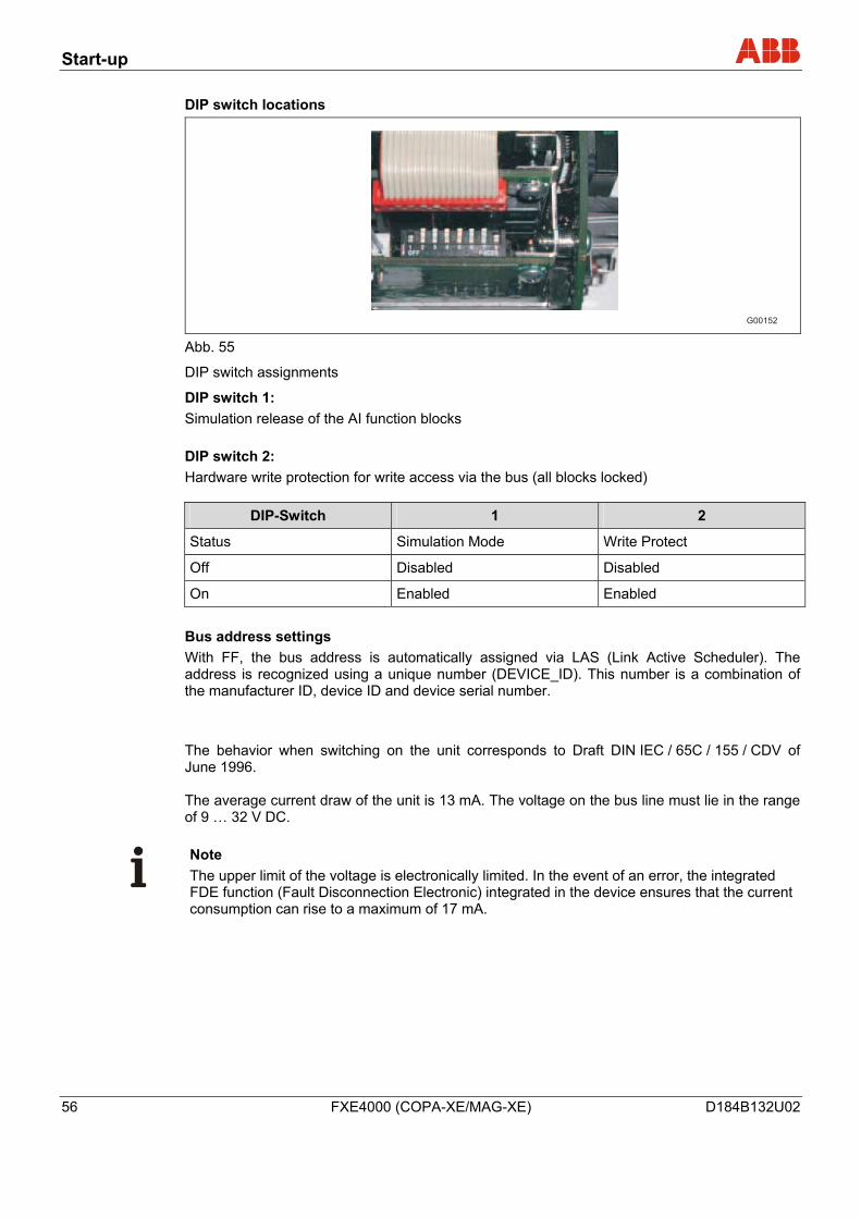
Start-up
56 FXE4000 (COPA-XE/MAG-XE) D184B132U02
DIP switch locations
G00152 Abb. 55
DIP switch assignments
DIP switch 1: Simulation release of the AI function blocks DIP switch 2: Hardware write protection for write access via the bus (all blocks locked)
DIP-Switch 1 2
Status Simulation Mode Write Protect
Off Disabled Disabled
On Enabled Enabled Bus address settings With FF, the bus address is automatically assigned via LAS (Link Active Scheduler). The address is recognized using a unique number (DEVICE_ID). This number is a combination of the manufacturer ID, device ID and device serial number.
The behavior when switching on the unit corresponds to Draft DIN IEC / 65C / 155 / CDV of June 1996. The average current draw of the unit is 13 mA. The voltage on the bus line must lie in the range of 9 … 32 V DC.
Note The upper limit of the voltage is electronically limited. In the event of an error, the integrated FDE function (Fault Disconnection Electronic) integrated in the device ensures that the current consumption can rise to a maximum of 17 mA.
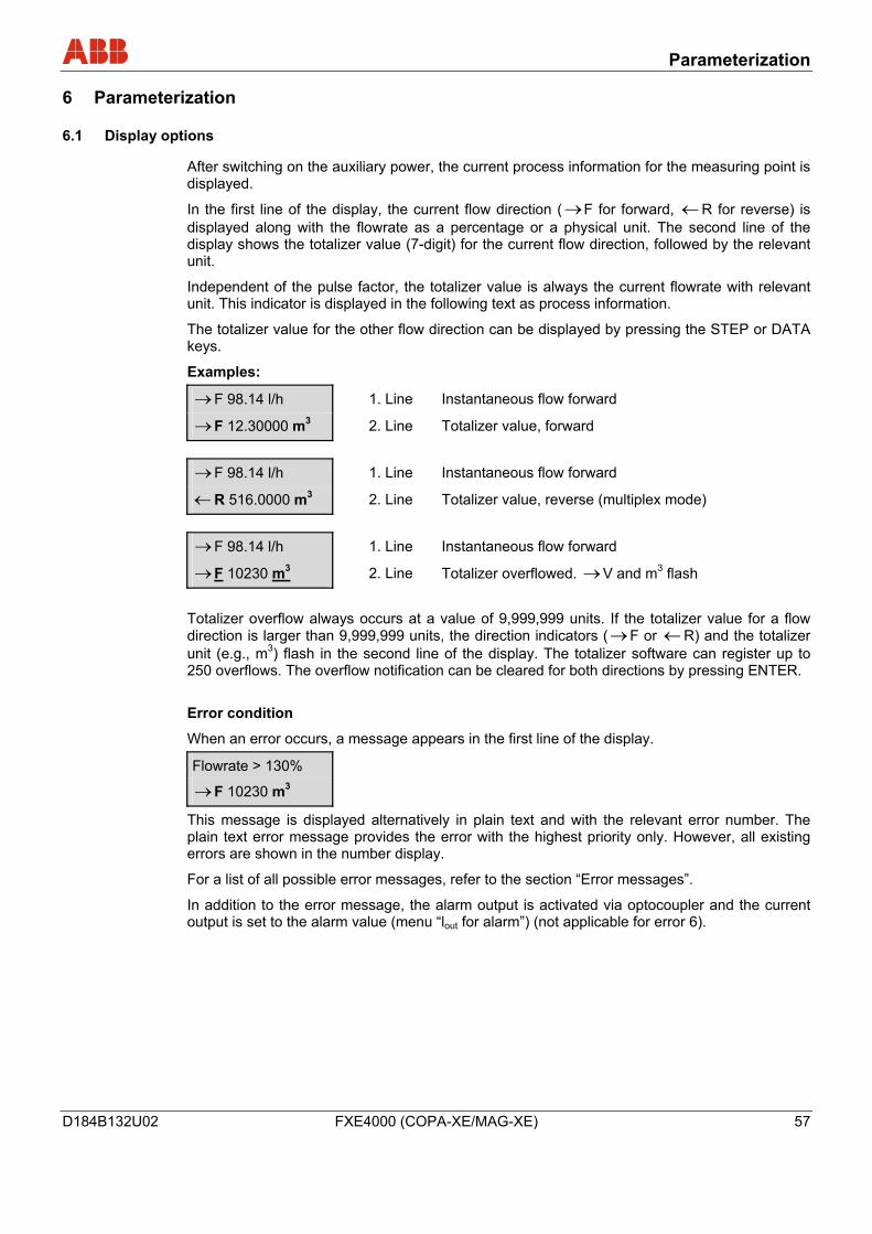
Parameterization
D184B132U02 FXE4000 (COPA-XE/MAG-XE) 57
6 Parameterization
6.1 Display options
After switching on the auxiliary power, the current process information for the measuring point is displayed.
In the first line of the display, the current flow direction ( →F for forward, ← R for reverse) is displayed along with the flowrate as a percentage or a physical unit. The second line of the display shows the totalizer value (7-digit) for the current flow direction, followed by the relevant unit.
Independent of the pulse factor, the totalizer value is always the current flowrate with relevant unit. This indicator is displayed in the following text as process information.
The totalizer value for the other flow direction can be displayed by pressing the STEP or DATA keys.
Examples:
→ F 98.14 l/h 1. Line Instantaneous flow forward
→ F 12.30000 m3 2. Line Totalizer value, forward → F 98.14 l/h 1. Line Instantaneous flow forward
← R 516.0000 m3 2. Line Totalizer value, reverse (multiplex mode) → F 98.14 l/h 1. Line Instantaneous flow forward
→ F 10230 m3 2. Line Totalizer overflowed. → V and m3 flash Totalizer overflow always occurs at a value of 9,999,999 units. If the totalizer value for a flow direction is larger than 9,999,999 units, the direction indicators ( → F or ← R) and the totalizer unit (e.g., m3) flash in the second line of the display. The totalizer software can register up to 250 overflows. The overflow notification can be cleared for both directions by pressing ENTER. Error condition
When an error occurs, a message appears in the first line of the display.
Flowrate > 130%
→ F 10230 m3
This message is displayed alternatively in plain text and with the relevant error number. The plain text error message provides the error with the highest priority only. However, all existing errors are shown in the number display.
For a list of all possible error messages, refer to the section “Error messages”.
In addition to the error message, the alarm output is activated via optocoupler and the current output is set to the alarm value (menu “lout for alarm”) (not applicable for error 6).
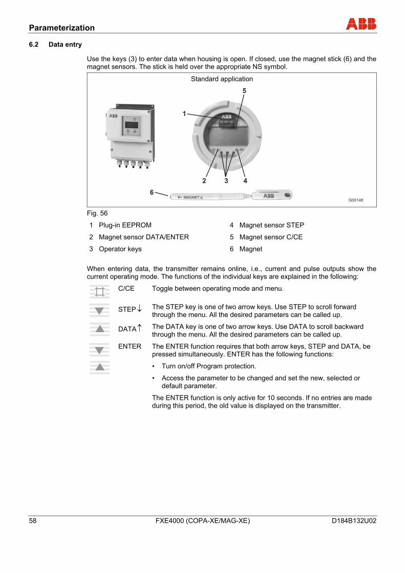
Parameterization
58 FXE4000 (COPA-XE/MAG-XE) D184B132U02
6.2 Data entry
Use the keys (3) to enter data when housing is open. If closed, use the magnet stick (6) and the magnet sensors. The stick is held over the appropriate NS symbol.
Standard application
G00148
1
5
2
6
3 4
Fig. 56
1 Plug-in EEPROM
2 Magnet sensor DATA/ENTER
3 Operator keys
4 Magnet sensor STEP
5 Magnet sensor C/CE
6 Magnet When entering data, the transmitter remains online, i.e., current and pulse outputs show the current operating mode. The functions of the individual keys are explained in the following:
C/CE Toggle between operating mode and menu.
STEP↓ The STEP key is one of two arrow keys. Use STEP to scroll forward
through the menu. All the desired parameters can be called up.
DATA↑ The DATA key is one of two arrow keys. Use DATA to scroll backward
through the menu. All the desired parameters can be called up.
ENTER The ENTER function requires that both arrow keys, STEP and DATA, be pressed simultaneously. ENTER has the following functions:
• Turn on/off Program protection.
• Access the parameter to be changed and set the new, selected or default parameter.
The ENTER function is only active for 10 seconds. If no entries are made during this period, the old value is displayed on the transmitter.
Parameterization
D184B132U02 FXE4000 (COPA-XE/MAG-XE) 59
ENTER function for magnet stick operation
The ENTER function is initiated when the DATA/ENTER sensor is activated for more than 3 seconds. The display flashes to indicate that the function is active.
There are two different methods of entering data:
• Numeric entry
• Entry from specified table
Note
When entering data, the values are checked for plausibility and, if necessary, rejected with an appropriate message.
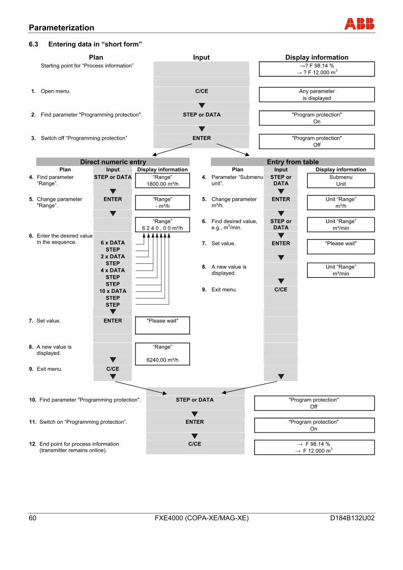
Parameterization
60 FXE4000 (COPA-XE/MAG-XE) D184B132U02
6.3 Entering data in “short form”
Plan Input Display information →? F 98.14 % Starting point for “Process information”
→ ? F 12.000 m3
Any parameter 1. Open menu. C/CE is displayed
"Program protection" 2. Find parameter "Programming protection". STEP or DATA On
"Program protection" 3. Switch off “Programming protection” ENTER Off
Direct numeric entry Entry from table Plan Input Display information Plan Input Display information
“Range” Submenu 4. Find parameter “Range”.
STEP or DATA 1800.00 m³/h
4. Parameter “Submenu unit”.
STEP or DATA Unit
“Range” Unit “Range” 5. Change parameter
"Range”. ENTER
- m³/h 5. Change parameter
m³/h. ENTER
m³/h
“Range” Unit “Range” 6 2 4 0 , 0 0 m³/h
6. Find desired value, e.g., m3/min.
STEP or DATA m³/min
"Please wait" 7. Set value. ENTER
Unit “Range” 8. A new value is displayed.
m³/min
6. Enter the desired value in the sequence.
6 x DATA
STEP 2 x DATA
STEP 4 x DATA
STEP STEP
10 x DATA STEP STEP
9. Exit menu. C/CE
7. Set value. ENTER "Please wait"
8. A new value is displayed.
“Range”
6240,00 m³/h
C/CE 9. Exit menu.
"Program protection" 10. Find parameter "Programming protection". STEP or DATA Off
"Program protection" 11. Switch on “Programming protection”. ENTER
On
→ F 98.14 % 12. End point for process information (transmitter remains online).
C/CE → F 12.000 m3
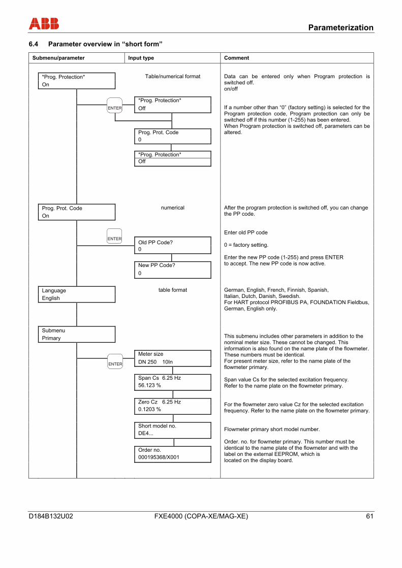
Parameterization
D184B132U02 FXE4000 (COPA-XE/MAG-XE) 61
6.4 Parameter overview in “short form”
Submenu/parameter Input type Comment
*Prog. Protection* Table/numerical format On *Prog. Protection* Off
Prog. Prot. Code 0
*Prog. Protection*
Off
Data can be entered only when Program protection is switched off. on/off If a number other than “0” (factory setting) is selected for the Program protection code, Program protection can only be switched off if this number (1-255) has been entered. When Program protection is switched off, parameters can be altered.
Prog. Prot. Code numerical On
Old PP Code?
0 New PP Code? 0
After the program protection is switched off, you can change the PP code. Enter old PP code 0 = factory setting. Enter the new PP code (1-255) and press ENTER to accept. The new PP code is now active.
Language table format English
German, English, French, Finnish, Spanish, Italian, Dutch, Danish, Swedish. For HART protocol PROFIBUS PA, FOUNDATION Fieldbus, German, English only.
Submenu Primary Meter size DN 250 10In Span Cs 6.25 Hz 56.123 % Zero Cz 6.25 Hz 0.1203 % Short model no. DE4... Order no. 000195368/X001
This submenu includes other parameters in addition to the nominal meter size. These cannot be changed. This information is also found on the name plate of the flowmeter. These numbers must be identical. For present meter size, refer to the name plate of the flowmeter primary. Span value Cs for the selected excitation frequency. Refer to the name plate on the flowmeter primary. For the flowmeter zero value Cz for the selected excitation frequency. Refer to the name plate on the flowmeter primary. Flowmeter primary short model number. Order. no. for flowmeter primary. This number must be identical to the name plate of the flowmeter and with the label on the external EEPROM, which is located on the display board.
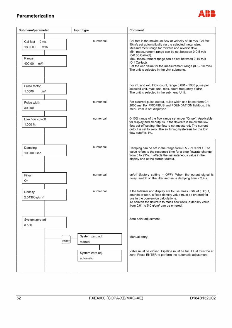
Parameterization
62 FXE4000 (COPA-XE/MAG-XE) D184B132U02
Submenu/parameter Input type Comment
Cal-fact 10m/s numerical
1800.00 m³/h
Range
400.00 m³/h
Cal-fact is the maximum flow at velocity of 10 m/s. Cal-fact 10 m/s set automatically via the selected meter size. Measurement range for forward and reverse flow. Min. measurement range can be set between 0-0.5 m/s (0-0.05 Cal-fact). Max. measurement range can be set between 0-10 m/s (0-1 Cal-fact). Set the end value for the measurement range (0.5 - 10 m/s). The unit is selected in the Unit submenu.
Pulse factor
1.0000 /m³ For int. and ext. Flow count, range 0.001 - 1000 pulse per selected unit, max. unit, max. count frequency 5 kHz. The unit is selected in the submenu Unit.
Pulse width numerical
30.000 For external pulse output, pulse width can be set from 0.1 - 2000 ms. For PROFIBUS and FOUNDATION fieldbus, this menu item is not displayed.
Low flow cut-off numerical
1.000 %
0-10% range of the flow range set under “Qmax”. Applicable for display and all outputs. If the flowrate is below the low flow cut-off setting, the flow is not measured. The current output is set to zero. The switching hysteresis for the low flow cutoff is 1%.
Damping numerical
10.0000 sec
Damping can be set in the range from 0.5 - 99.9999 s. The value refers to the response time for a step flowrate change from 0 to 99%. It affects the instantaneous value in the display and at the current output.
Filter numerical
On
on/off (factory setting = OFF). When the output signal is noisy, switch on the filter and set a damping time > 2.4 s.
Density numerical
2.54300 g/cm³
If the totalizer and display are to use mass units of g, kg, t, pounds or uton, a fixed density value must be entered for use in the conversion calculations. To convert the flowrate to mass flow units, a density value from 0.01 to 5.0 g/cm³ can be entered.
System zero adj
3.5Hz
System zero adj.
manual
System zero adj.
automatic
Zero point adjustment. Manual entry. Valve must be closed. Pipeline must be full. Fluid must be at zero. Press ENTER to perform the automatic adjustment.
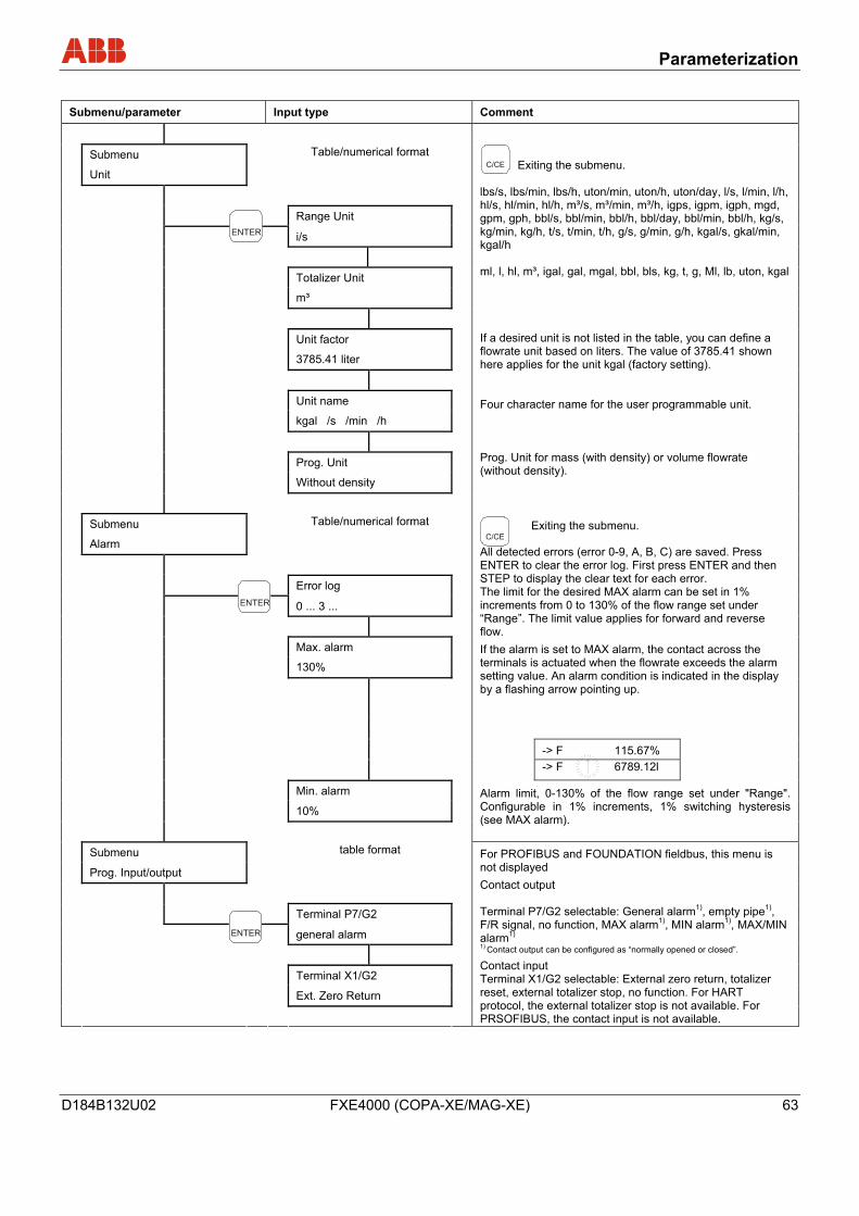
Parameterization
D184B132U02 FXE4000 (COPA-XE/MAG-XE) 63
Submenu/parameter Input type Comment
Submenu Table/numerical format
Unit
Range Unit
i/s
Totalizer Unit
m³
Unit factor
3785.41 liter
Unit name
kgal /s /min /h
Prog. Unit
Without density
Exiting the submenu. lbs/s, lbs/min, lbs/h, uton/min, uton/h, uton/day, l/s, l/min, l/h, hl/s, hl/min, hl/h, m³/s, m³/min, m³/h, igps, igpm, igph, mgd, gpm, gph, bbl/s, bbl/min, bbl/h, bbl/day, bbl/min, bbl/h, kg/s, kg/min, kg/h, t/s, t/min, t/h, g/s, g/min, g/h, kgal/s, gkal/min, kgal/h ml, l, hl, m³, igal, gal, mgal, bbl, bls, kg, t, g, Ml, lb, uton, kgal If a desired unit is not listed in the table, you can define a flowrate unit based on liters. The value of 3785.41 shown here applies for the unit kgal (factory setting). Four character name for the user programmable unit. Prog. Unit for mass (with density) or volume flowrate (without density).
Submenu Table/numerical format
Alarm
Error log
0 ... 3 ...
Max. alarm
130%
Exiting the submenu.
All detected errors (error 0-9, A, B, C) are saved. Press ENTER to clear the error log. First press ENTER and then STEP to display the clear text for each error. The limit for the desired MAX alarm can be set in 1% increments from 0 to 130% of the flow range set under “Range”. The limit value applies for forward and reverse flow. If the alarm is set to MAX alarm, the contact across the terminals is actuated when the flowrate exceeds the alarm setting value. An alarm condition is indicated in the display by a flashing arrow pointing up.
-> F 115.67% -> F 6789.12l
Min. alarm
10%
Alarm limit, 0-130% of the flow range set under "Range". Configurable in 1% increments, 1% switching hysteresis (see MAX alarm).
Submenu table format
Prog. Input/output
Terminal P7/G2
general alarm
Terminal X1/G2
Ext. Zero Return
For PROFIBUS and FOUNDATION fieldbus, this menu is not displayed Contact output Terminal P7/G2 selectable: General alarm1), empty pipe1), F/R signal, no function, MAX alarm1), MIN alarm1), MAX/MIN alarm1) 1) Contact output can be configured as “normally opened or closed”.
Contact input Terminal X1/G2 selectable: External zero return, totalizer reset, external totalizer stop, no function. For HART protocol, the external totalizer stop is not available. For PRSOFIBUS, the contact input is not available.
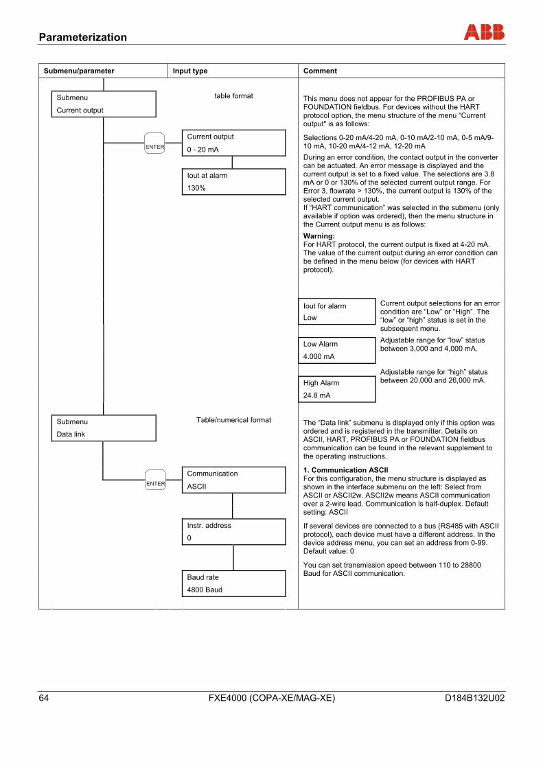
Parameterization
64 FXE4000 (COPA-XE/MAG-XE) D184B132U02
Submenu/parameter Input type Comment
Submenu table format
Current output
Current output
0 - 20 mA
Iout at alarm
130%
This menu does not appear for the PROFIBUS PA or FOUNDATION fieldbus. For devices without the HART protocol option, the menu structure of the menu “Current output" is as follows:
Selections 0-20 mA/4-20 mA, 0-10 mA/2-10 mA, 0-5 mA/9-10 mA, 10-20 mA/4-12 mA, 12-20 mA During an error condition, the contact output in the converter can be actuated. An error message is displayed and the current output is set to a fixed value. The selections are 3.8 mA or 0 or 130% of the selected current output range. For Error 3, flowrate > 130%, the current output is 130% of the selected current output. If “HART communication” was selected in the submenu (only available if option was ordered), then the menu structure in the Current output menu is as follows: Warning: For HART protocol, the current output is fixed at 4-20 mA. The value of the current output during an error condition can be defined in the menu below (for devices with HART protocol).
Iout for alarm Low
Low Alarm 4.000 mA
High Alarm 24.8 mA
Current output selections for an error condition are “Low” or “High”. The “low” or “high” status is set in the subsequent menu. Adjustable range for “low” status between 3,000 and 4,000 mA. Adjustable range for “high” status between 20,000 and 26,000 mA.
Submenu Table/numerical format
Data link
Communication
ASCII
Instr. address
0
Baud rate
4800 Baud
The “Data link” submenu is displayed only if this option was ordered and is registered in the transmitter. Details on ASCII, HART, PROFIBUS PA or FOUNDATION fieldbus communication can be found in the relevant supplement to the operating instructions.
1. Communication ASCII For this configuration, the menu structure is displayed as shown in the interface submenu on the left: Select from ASCII or ASCII2w. ASCII2w means ASCII communication over a 2-wire lead. Communication is half-duplex. Default setting: ASCII
If several devices are connected to a bus (RS485 with ASCII protocol), each device must have a different address. In the device address menu, you can set an address from 0-99. Default value: 0
You can set transmission speed between 110 to 28800 Baud for ASCII communication.
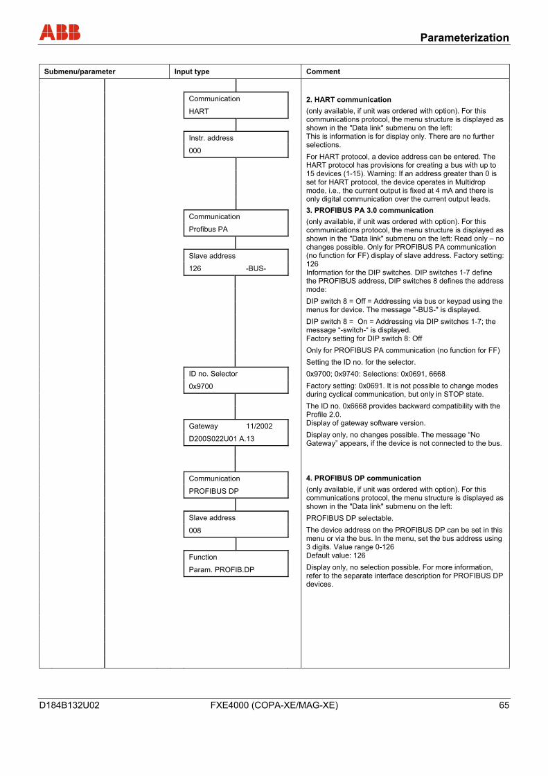
Parameterization
D184B132U02 FXE4000 (COPA-XE/MAG-XE) 65
Submenu/parameter Input type Comment
Communication
HART
Instr. address
000
Communication
Profibus PA
Slave address
126 -BUS-
ID no. Selector
0x9700
Gateway 11/2002
D200S022U01 A.13
Communication
PROFIBUS DP
Slave address
008
Function
Param. PROFIB.DP
2. HART communication (only available, if unit was ordered with option). For this communications protocol, the menu structure is displayed as shown in the "Data link" submenu on the left: This is information is for display only. There are no further selections. For HART protocol, a device address can be entered. The HART protocol has provisions for creating a bus with up to 15 devices (1-15). Warning: If an address greater than 0 is set for HART protocol, the device operates in Multidrop mode, i.e., the current output is fixed at 4 mA and there is only digital communication over the current output leads. 3. PROFIBUS PA 3.0 communication (only available, if unit was ordered with option). For this communications protocol, the menu structure is displayed as shown in the "Data link" submenu on the left: Read only – no changes possible. Only for PROFIBUS PA communication (no function for FF) display of slave address. Factory setting: 126 Information for the DIP switches. DIP switches 1-7 define the PROFIBUS address, DIP switches 8 defines the address mode: DIP switch 8 = Off = Addressing via bus or keypad using the menus for device. The message "-BUS-" is displayed. DIP switch 8 = On = Addressing via DIP switches 1-7; the message “-switch-“ is displayed. Factory setting for DIP switch 8: Off Only for PROFIBUS PA communication (no function for FF) Setting the ID no. for the selector. 0x9700; 0x9740: Selections: 0x0691, 6668 Factory setting: 0x0691. It is not possible to change modes during cyclical communication, but only in STOP state. The ID no. 0x6668 provides backward compatibility with the Profile 2.0. Display of gateway software version. Display only, no changes possible. The message “No Gateway” appears, if the device is not connected to the bus. 4. PROFIBUS DP communication (only available, if unit was ordered with option). For this communications protocol, the menu structure is displayed as shown in the "Data link" submenu on the left: PROFIBUS DP selectable. The device address on the PROFIBUS DP can be set in this menu or via the bus. In the menu, set the bus address using 3 digits. Value range 0-126 Default value: 126 Display only, no selection possible. For more information, refer to the separate interface description for PROFIBUS DP devices.
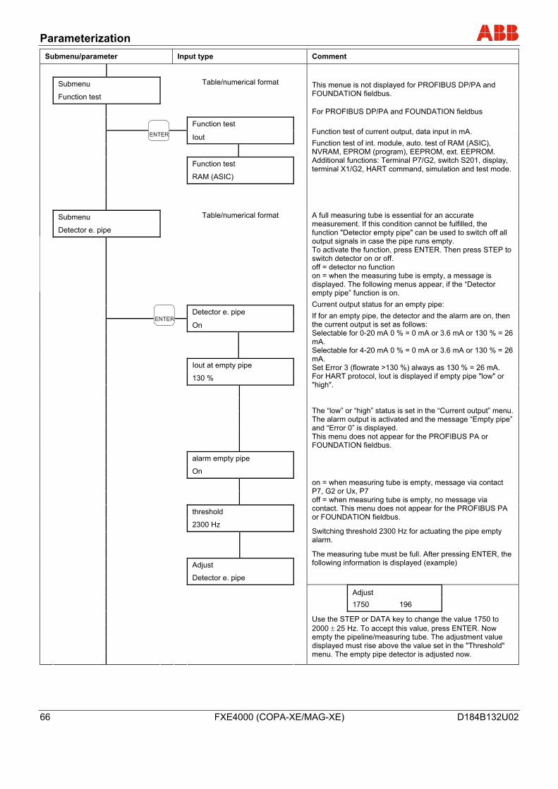
Parameterization
66 FXE4000 (COPA-XE/MAG-XE) D184B132U02
Submenu/parameter Input type Comment
Submenu Table/numerical format
Function test This menue is not displayed for PROFIBUS DP/PA and FOUNDATION fieldbus.
Function test
Iout
Function test
RAM (ASIC)
For PROFIBUS DP/PA and FOUNDATION fieldbus Function test of current output, data input in mA. Function test of int. module, auto. test of RAM (ASIC), NVRAM, EPROM (program), EEPROM, ext. EEPROM. Additional functions: Terminal P7/G2, switch S201, display, terminal X1/G2, HART command, simulation and test mode.
Submenu Table/numerical format
Detector e. pipe
Detector e. pipe
On
Iout at empty pipe
130 %
alarm empty pipe
On
threshold
2300 Hz
Adjust
Detector e. pipe
A full measuring tube is essential for an accurate measurement. If this condition cannot be fulfilled, the function "Detector empty pipe" can be used to switch off all output signals in case the pipe runs empty. To activate the function, press ENTER. Then press STEP to switch detector on or off. off = detector no function on = when the measuring tube is empty, a message is displayed. The following menus appear, if the “Detector empty pipe” function is on. Current output status for an empty pipe: If for an empty pipe, the detector and the alarm are on, then the current output is set as follows: Selectable for 0-20 mA 0 % = 0 mA or 3.6 mA or 130 % = 26 mA. Selectable for 4-20 mA 0 % = 0 mA or 3.6 mA or 130 % = 26 mA. Set Error 3 (flowrate >130 %) always as 130 % = 26 mA. For HART protocol, lout is displayed if empty pipe "low" or "high". The “low” or “high” status is set in the “Current output” menu. The alarm output is activated and the message “Empty pipe” and “Error 0” is displayed. This menu does not appear for the PROFIBUS PA or FOUNDATION fieldbus. on = when measuring tube is empty, message via contact P7, G2 or Ux, P7 off = when measuring tube is empty, no message via contact. This menu does not appear for the PROFIBUS PA or FOUNDATION fieldbus.
Switching threshold 2300 Hz for actuating the pipe empty alarm.
The measuring tube must be full. After pressing ENTER, the following information is displayed (example)
Adjust 1750 196
Use the STEP or DATA key to change the value 1750 to 2000 ± 25 Hz. To accept this value, press ENTER. Now empty the pipeline/measuring tube. The adjustment value displayed must rise above the value set in the "Threshold" menu. The empty pipe detector is adjusted now.
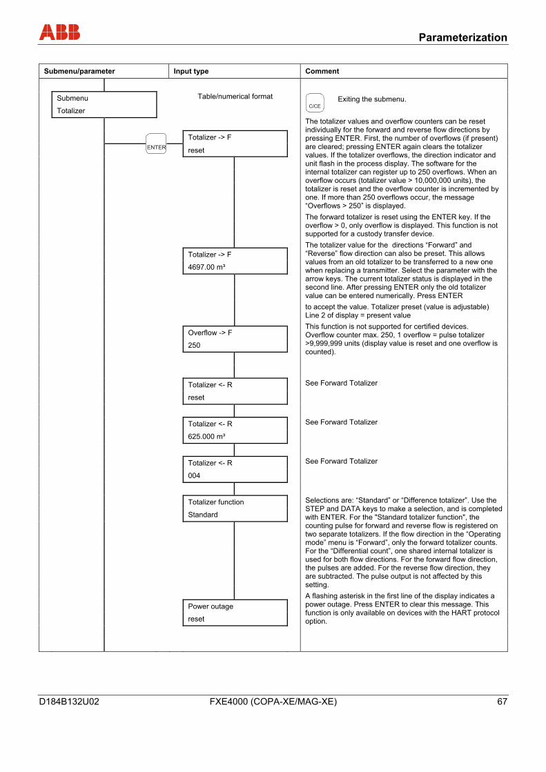
Parameterization
D184B132U02 FXE4000 (COPA-XE/MAG-XE) 67
Submenu/parameter Input type Comment
Submenu Table/numerical format
Totalizer
Totalizer -> F
reset
Totalizer -> F
4697.00 m³
Overflow -> F
250
Exiting the submenu.
The totalizer values and overflow counters can be reset individually for the forward and reverse flow directions by pressing ENTER. First, the number of overflows (if present) are cleared; pressing ENTER again clears the totalizer values. If the totalizer overflows, the direction indicator and unit flash in the process display. The software for the internal totalizer can register up to 250 overflows. When an overflow occurs (totalizer value > 10,000,000 units), the totalizer is reset and the overflow counter is incremented by one. If more than 250 overflows occur, the message “Overflows > 250” is displayed. The forward totalizer is reset using the ENTER key. If the overflow > 0, only overflow is displayed. This function is not supported for a custody transfer device. The totalizer value for the directions “Forward” and “Reverse” flow direction can also be preset. This allows values from an old totalizer to be transferred to a new one when replacing a transmitter. Select the parameter with the arrow keys. The current totalizer status is displayed in the second line. After pressing ENTER only the old totalizer value can be entered numerically. Press ENTER to accept the value. Totalizer preset (value is adjustable) Line 2 of display = present value This function is not supported for certified devices. Overflow counter max. 250, 1 overflow = pulse totalizer >9,999,999 units (display value is reset and one overflow is counted).
Totalizer <- R
reset See Forward Totalizer
Totalizer <- R
625.000 m³ See Forward Totalizer
Totalizer <- R
004 See Forward Totalizer
Totalizer function
Standard
Power outage
reset
Selections are: “Standard” or “Difference totalizer”. Use the STEP and DATA keys to make a selection, and is completed with ENTER. For the "Standard totalizer function", the counting pulse for forward and reverse flow is registered on two separate totalizers. If the flow direction in the “Operating mode” menu is “Forward”, only the forward totalizer counts. For the “Differential count”, one shared internal totalizer is used for both flow directions. For the forward flow direction, the pulses are added. For the reverse flow direction, they are subtracted. The pulse output is not affected by this setting. A flashing asterisk in the first line of the display indicates a power outage. Press ENTER to clear this message. This function is only available on devices with the HART protocol option.
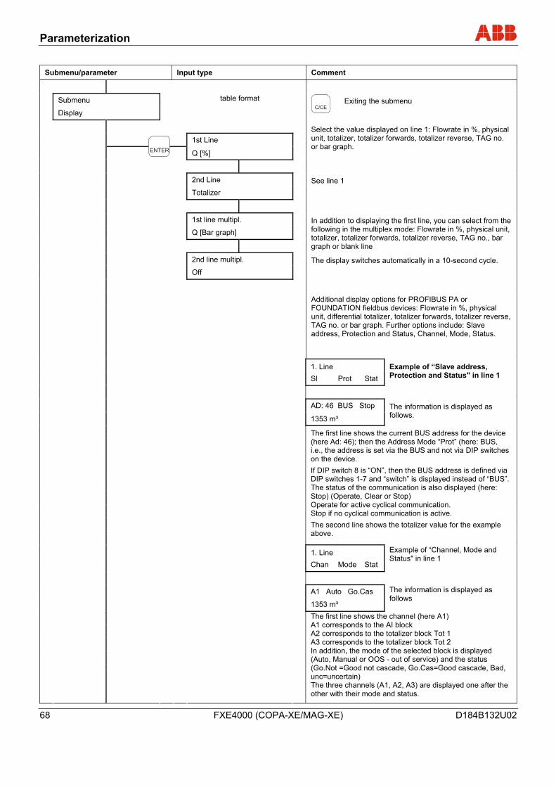
Parameterization
68 FXE4000 (COPA-XE/MAG-XE) D184B132U02
Submenu/parameter Input type Comment
Submenu table format
Display
1st Line
Q [%]
Exiting the submenu
Select the value displayed on line 1: Flowrate in %, physical unit, totalizer, totalizer forwards, totalizer reverse, TAG no. or bar graph.
2nd Line
Totalizer See line 1
1st line multipl.
Q [Bar graph]
In addition to displaying the first line, you can select from the following in the multiplex mode: Flowrate in %, physical unit, totalizer, totalizer forwards, totalizer reverse, TAG no., bar graph or blank line
2nd line multipl.
Off The display switches automatically in a 10-second cycle.
Additional display options for PROFIBUS PA or FOUNDATION fieldbus devices: Flowrate in %, physical unit, differential totalizer, totalizer forwards, totalizer reverse, TAG no. or bar graph. Further options include: Slave address, Protection and Status, Channel, Mode, Status.
1. Line Sl Prot Stat
Example of “Slave address, Protection and Status" in line 1
AD: 46 BUS Stop 1353 m³
The information is displayed as follows.
The first line shows the current BUS address for the device (here Ad: 46); then the Address Mode “Prot” (here: BUS, i.e., the address is set via the BUS and not via DIP switches on the device. If DIP switch 8 is “ON”, then the BUS address is defined via DIP switches 1-7 and “switch” is displayed instead of “BUS”. The status of the communication is also displayed (here: Stop) (Operate, Clear or Stop) Operate for active cyclical communication. Stop if no cyclical communication is active. The second line shows the totalizer value for the example above.
1. Line Chan Mode Stat
Example of “Channel, Mode and Status" in line 1
A1 Auto Go.Cas 1353 m³
The information is displayed as follows
The first line shows the channel (here A1) A1 corresponds to the AI block A2 corresponds to the totalizer block Tot 1 A3 corresponds to the totalizer block Tot 2 In addition, the mode of the selected block is displayed (Auto, Manual or OOS - out of service) and the status (Go.Not =Good not cascade, Go.Cas=Good cascade, Bad, unc=uncertain) The three channels (A1, A2, A3) are displayed one after the other with their mode and status.
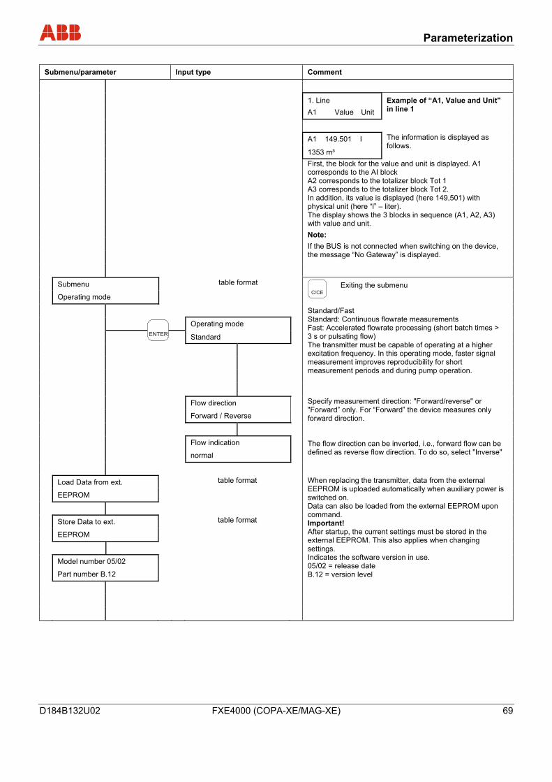
Parameterization
D184B132U02 FXE4000 (COPA-XE/MAG-XE) 69
Submenu/parameter Input type Comment
1. Line A1 Value Unit
Example of “A1, Value and Unit" in line 1
A1 149.501 I 1353 m³
The information is displayed as follows.
First, the block for the value and unit is displayed. A1 corresponds to the AI block A2 corresponds to the totalizer block Tot 1 A3 corresponds to the totalizer block Tot 2. In addition, its value is displayed (here 149,501) with physical unit (here “l” – liter). The display shows the 3 blocks in sequence (A1, A2, A3) with value and unit. Note: If the BUS is not connected when switching on the device, the message “No Gateway” is displayed.
Submenu table format
Operating mode
Operating mode
Standard
Exiting the submenu
Standard/Fast Standard: Continuous flowrate measurements Fast: Accelerated flowrate processing (short batch times > 3 s or pulsating flow) The transmitter must be capable of operating at a higher excitation frequency. In this operating mode, faster signal measurement improves reproducibility for short measurement periods and during pump operation.
Flow direction
Forward / Reverse Specify measurement direction: "Forward/reverse" or "Forward” only. For “Forward” the device measures only forward direction.
Flow indication
normal The flow direction can be inverted, i.e., forward flow can be defined as reverse flow direction. To do so, select "Inverse"
Load Data from ext. table format
EEPROM
Store Data to ext. table format
EEPROM
Model number 05/02
Part number B.12
When replacing the transmitter, data from the external EEPROM is uploaded automatically when auxiliary power is switched on. Data can also be loaded from the external EEPROM upon command. Important! After startup, the current settings must be stored in the external EEPROM. This also applies when changing settings. Indicates the software version in use. 05/02 = release date B.12 = version level
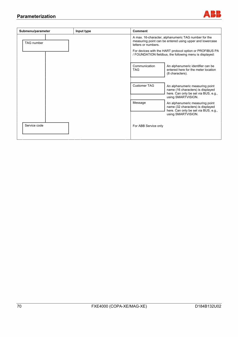
Parameterization
70 FXE4000 (COPA-XE/MAG-XE) D184B132U02
Submenu/parameter Input type Comment
TAG number
A max. 16-character, alphanumeric TAG number for the measuring point can be entered using upper and lowercase letters or numbers.
For devices with the HART protocol option or PROFIBUS PA / FOUNDATION fieldbus, the following menu is displayed:
Communication TAG
An alphanumeric identifier can be entered here for the meter location (8 characters).
Customer TAG
An alphanumeric measuring point name (16 characters) is displayed here. Can only be set via BUS, e.g., using SMARTVISION.
Message
An alphanumeric measuring point name (32 characters) is displayed here. Can only be set via BUS, e.g., using SMARTVISION.
Service code
For ABB Service only
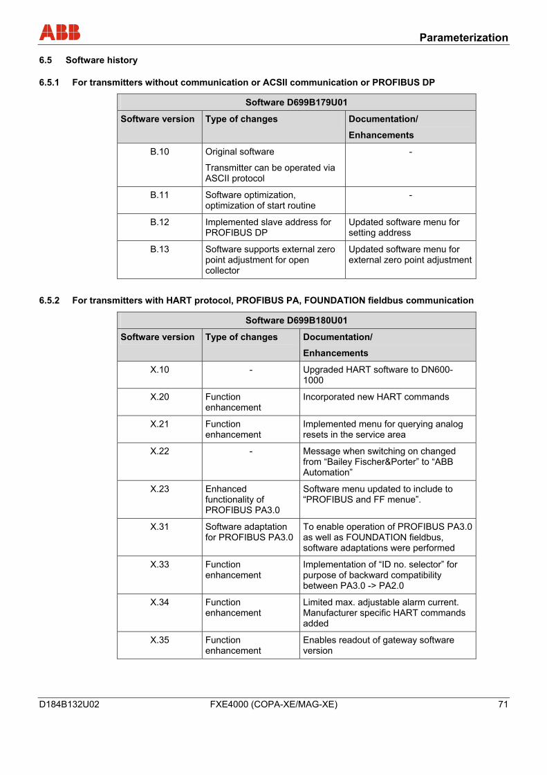
Parameterization
D184B132U02 FXE4000 (COPA-XE/MAG-XE) 71
6.5 Software history
6.5.1 For transmitters without communication or ACSII communication or PROFIBUS DP
Software D699B179U01
Software version Type of changes Documentation/
Enhancements
B.10 Original software
Transmitter can be operated via ASCII protocol
-
B.11 Software optimization, optimization of start routine
-
B.12 Implemented slave address for PROFIBUS DP
Updated software menu for setting address
B.13 Software supports external zero point adjustment for open collector
Updated software menu for external zero point adjustment
6.5.2 For transmitters with HART protocol, PROFIBUS PA, FOUNDATION fieldbus communication
Software D699B180U01
Software version Type of changes Documentation/
Enhancements
X.10 - Upgraded HART software to DN600-1000
X.20 Function enhancement
Incorporated new HART commands
X.21 Function enhancement
Implemented menu for querying analog resets in the service area
X.22 - Message when switching on changed from “Bailey Fischer&Porter” to “ABB Automation”
X.23 Enhanced functionality of PROFIBUS PA3.0
Software menu updated to include to “PROFIBUS and FF menue”.
X.31 Software adaptation for PROFIBUS PA3.0
To enable operation of PROFIBUS PA3.0 as well as FOUNDATION fieldbus, software adaptations were performed
X.33 Function enhancement
Implementation of “ID no. selector” for purpose of backward compatibility between PA3.0 -> PA2.0
X.34 Function enhancement
Limited max. adjustable alarm current. Manufacturer specific HART commands added
X.35 Function enhancement
Enables readout of gateway software version
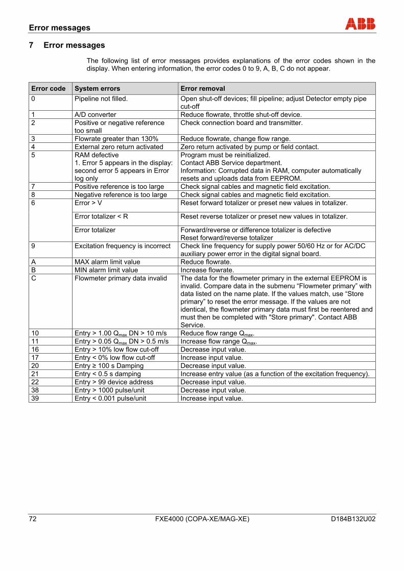
Error messages
72 FXE4000 (COPA-XE/MAG-XE) D184B132U02
7 Error messages
The following list of error messages provides explanations of the error codes shown in the display. When entering information, the error codes 0 to 9, A, B, C do not appear.
Error code System errors Error removal 0 Pipeline not filled. Open shut-off devices; fill pipeline; adjust Detector empty pipe
cut-off 1 A/D converter Reduce flowrate, throttle shut-off device. 2 Positive or negative reference
too small Check connection board and transmitter.
3 Flowrate greater than 130% Reduce flowrate, change flow range. 4 External zero return activated Zero return activated by pump or field contact. 5 RAM defective
1. Error 5 appears in the display: second error 5 appears in Error log only
Program must be reinitialized. Contact ABB Service department. Information: Corrupted data in RAM, computer automatically resets and uploads data from EEPROM.
7 Positive reference is too large Check signal cables and magnetic field excitation. 8 Negative reference is too large Check signal cables and magnetic field excitation.
Error > V Reset forward totalizer or preset new values in totalizer.
Error totalizer < R Reset reverse totalizer or preset new values in totalizer.
6
Error totalizer Forward/reverse or difference totalizer is defective Reset forward/reverse totalizer
9 Excitation frequency is incorrect Check line frequency for supply power 50/60 Hz or for AC/DC auxiliary power error in the digital signal board.
A MAX alarm limit value Reduce flowrate. B MIN alarm limit value Increase flowrate. C Flowmeter primary data invalid The data for the flowmeter primary in the external EEPROM is
invalid. Compare data in the submenu “Flowmeter primary” with data listed on the name plate. If the values match, use “Store primary” to reset the error message. If the values are not identical, the flowmeter primary data must first be reentered and must then be completed with "Store primary". Contact ABB Service.
10 Entry > 1.00 Qmax DN > 10 m/s Reduce flow range Qmax. 11 Entry > 0.05 Qmax DN > 0.5 m/s Increase flow range Qmax. 16 Entry > 10% low flow cut-off Decrease input value. 17 Entry < 0% low flow cut-off Increase input value. 20 Entry ≥ 100 s Damping Decrease input value. 21 Entry < 0.5 s damping Increase entry value (as a function of the excitation frequency). 22 Entry > 99 device address Decrease input value. 38 Entry > 1000 pulse/unit Decrease input value. 39 Entry < 0.001 pulse/unit Increase input value.
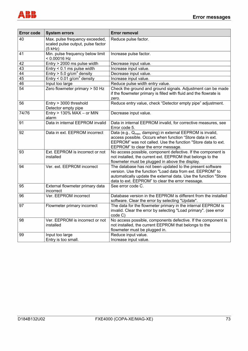
Error messages
D184B132U02 FXE4000 (COPA-XE/MAG-XE) 73
Error code System errors Error removal 40 Max. pulse frequency exceeded,
scaled pulse output, pulse factor (5 kHz)
Reduce pulse factor.
41 Min. pulse frequency below limit < 0.00016 Hz
Increase pulse factor.
42 Entry > 2000 ms pulse width Decrease input value. 43 Entry < 0.1 ms pulse width Increase input value. 44 Entry > 5.0 g/cm3 density Decrease input value. 45 Entry < 0.01 g/cm3 density Increase input value. 46 Input too large Reduce pulse width entry value. 54 Zero flowmeter primary > 50 Hz Check the ground and ground signals. Adjustment can be made
if the flowmeter primary is filled with fluid and the flowrate is zero.
56 Entry > 3000 threshold Detector empty pipe
Reduce entry value, check “Detector empty pipe” adjustment.
74/76 Entry > 130% MAX – or MIN alarm
Decrease input value.
91 Data in internal EEPROM invalid Data in internal EEPROM invalid, for corrective measures, see Error code 5.
92 Data in ext. EEPROM incorrect Data (e.g., Qmax, damping) in external EEPROM is invalid, access possible. Occurs when function “Store data in ext. EEPROM” was not called. Use the function "Store data to ext. EEPROM” to clear the error message.
93 Ext. EEPROM is incorrect or not installed
No access possible, component defective. If the component is not installed, the current ext. EEPROM that belongs to the flowmeter must be plugged in above the display.
94 Ver. ext. EEPROM incorrect The database has not been updated to the present software version. Use the function "Load data from ext. EEPROM” to automatically update the external data. Use the function "Store data to ext. EEPROM” to clear the error message.
95 External flowmeter primary data incorrect
See error code C.
96 Ver. EEPROM incorrect Database version in the EEPROM is different from the installed software. Clear the error by selecting "Update".
97 Flowmeter primary incorrect The data for the flowmeter primary in the internal EEPROM is invalid. Clear the error by selecting "Load primary". (see error code C)
98 Ver. EEPROM is incorrect or not installed
No access possible, components defective. If the component is not installed, the current EEPROM that belongs to the flowmeter must be plugged in.
99 Input too large Entry is too small.
Reduce input value. Increase input value.
Maintenance / Repair
74 FXE4000 (COPA-XE/MAG-XE) D184B132U02
8 Maintenance / Repair
Repair and maintenance activities may only be performed by authorized customer service personnel.
When replacing or repairing individual components, original spare parts must be used.
Caution - Potential damage to parts! The electronic components of the printed circuit board can be damaged by static electricity (observe ESD guidelines). Make sure that the static electricity in your body is discharged when touching electronic components.
Warning – Electrical voltage risk! When the housing is open, EMC protection is impaired and protection against contact is suspended. Before opening the housing, switch off power to all connecting cables.
8.1 Flowmeter primary
Essentially no maintenance is required for the flowmeter primary. The following items should be checked annually:
• Ambient conditions (air circulation, humidity)
• Seal integrity of the process connections
• Cable entry points and cover screws,
• Operational reliability of the auxiliary power feed, the lightning protection and the grounds
The flowmeter primary electrodes must be cleaned when the flowrate information on the transmitter changes when recording the identical flowrate volume. If the display shows a higher flowrate, the contamination is insulating. If the flowrate displayed is lower, the contamination results in a short-circuit.
For repairs to the lining, electrodes or magnet coil, the flowmeter must be returned to the local office of ABB.
Note
When sending the flowmeter to the local office of ABB, complete the return form in the appendix and include with device.
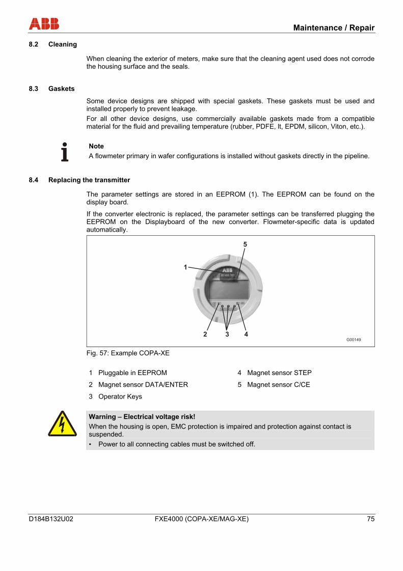
Maintenance / Repair
D184B132U02 FXE4000 (COPA-XE/MAG-XE) 75
8.2 Cleaning
When cleaning the exterior of meters, make sure that the cleaning agent used does not corrode the housing surface and the seals.
8.3 Gaskets
Some device designs are shipped with special gaskets. These gaskets must be used and installed properly to prevent leakage. For all other device designs, use commercially available gaskets made from a compatible material for the fluid and prevailing temperature (rubber, PDFE, lt, EPDM, silicon, Viton, etc.).
Note A flowmeter primary in wafer configurations is installed without gaskets directly in the pipeline.
8.4 Replacing the transmitter
The parameter settings are stored in an EEPROM (1). The EEPROM can be found on the display board.
If the converter electronic is replaced, the parameter settings can be transferred plugging the EEPROM on the Displayboard of the new converter. Flowmeter-specific data is updated automatically.
G00149
1
5
2 3 4
Fig. 57: Example COPA-XE 1 Pluggable in EEPROM
2 Magnet sensor DATA/ENTER
3 Operator Keys
4 Magnet sensor STEP
5 Magnet sensor C/CE
Warning – Electrical voltage risk! When the housing is open, EMC protection is impaired and protection against contact is suspended. • Power to all connecting cables must be switched off.
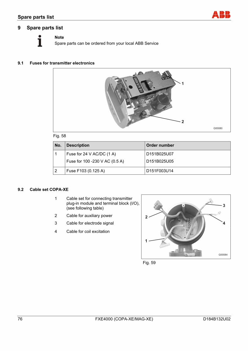
Spare parts list
76 FXE4000 (COPA-XE/MAG-XE) D184B132U02
9 Spare parts list
Note Spare parts can be ordered from your local ABB Service
9.1 Fuses for transmitter electronics
1
2
G00080 Fig. 58
No. Description Order number
1 Fuse for 24 V AC/DC (1 A)
Fuse for 100 -230 V AC (0.5 A)
D151B025U07
D151B025U05
2 Fuse F103 (0.125 A) D151F003U14
9.2 Cable set COPA-XE
1 Cable set for connecting transmitter plug-in module and terminal block (I/O), (see following table)
2 Cable for auxiliary power
3 Cable for electrode signal
4 Cable for coil excitation
1
2
3
4
G00084
Fig. 59
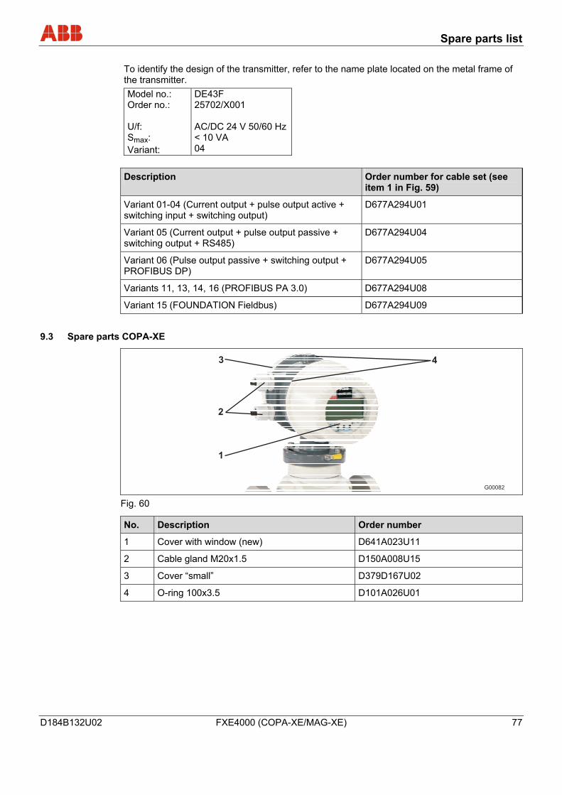
Spare parts list
D184B132U02 FXE4000 (COPA-XE/MAG-XE) 77
To identify the design of the transmitter, refer to the name plate located on the metal frame of the transmitter. Model no.: Order no.: U/f: Smax: Variant:
DE43F 25702/X001 AC/DC 24 V 50/60 Hz < 10 VA 04
Description Order number for cable set (see item 1 in Fig. 59)
Variant 01-04 (Current output + pulse output active + switching input + switching output)
D677A294U01
Variant 05 (Current output + pulse output passive + switching output + RS485)
D677A294U04
Variant 06 (Pulse output passive + switching output + PROFIBUS DP)
D677A294U05
Variants 11, 13, 14, 16 (PROFIBUS PA 3.0) D677A294U08
Variant 15 (FOUNDATION Fieldbus) D677A294U09
9.3 Spare parts COPA-XE
1
2
3 4
G00082 Fig. 60
No. Description Order number
1 Cover with window (new) D641A023U11
2 Cable gland M20x1.5 D150A008U15
3 Cover “small” D379D167U02
4 O-ring 100x3.5 D101A026U01
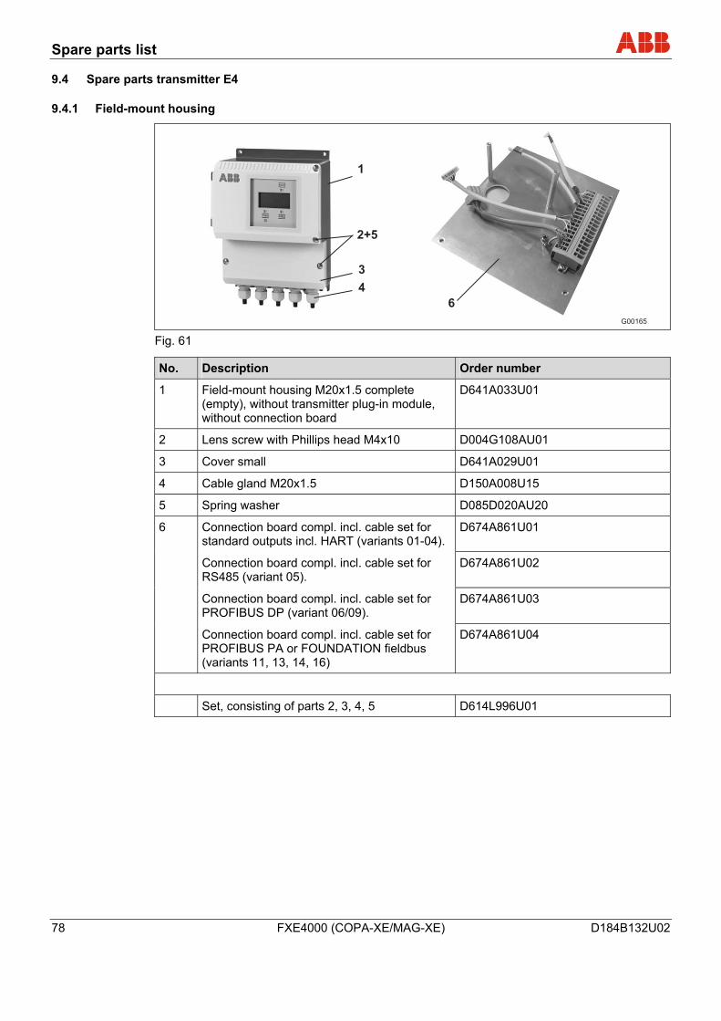
Spare parts list
78 FXE4000 (COPA-XE/MAG-XE) D184B132U02
9.4 Spare parts transmitter E4
9.4.1 Field-mount housing
2+5
1
6
G00165
3
4
Fig. 61
No. Description Order number
1 Field-mount housing M20x1.5 complete (empty), without transmitter plug-in module, without connection board
D641A033U01
2 Lens screw with Phillips head M4x10 D004G108AU01
3 Cover small D641A029U01
4 Cable gland M20x1.5 D150A008U15
5 Spring washer D085D020AU20
6 Connection board compl. incl. cable set for standard outputs incl. HART (variants 01-04).
D674A861U01
Connection board compl. incl. cable set for RS485 (variant 05).
D674A861U02
Connection board compl. incl. cable set for PROFIBUS DP (variant 06/09).
D674A861U03
Connection board compl. incl. cable set for PROFIBUS PA or FOUNDATION fieldbus (variants 11, 13, 14, 16)
D674A861U04
Set, consisting of parts 2, 3, 4, 5 D614L996U01
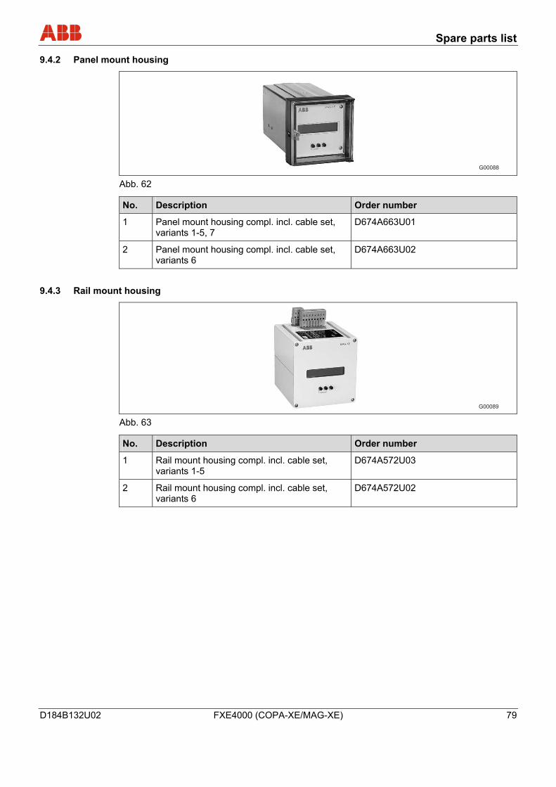
Spare parts list
D184B132U02 FXE4000 (COPA-XE/MAG-XE) 79
9.4.2 Panel mount housing
G00088 Abb. 62
No. Description Order number
1 Panel mount housing compl. incl. cable set, variants 1-5, 7
D674A663U01
2 Panel mount housing compl. incl. cable set, variants 6
D674A663U02
9.4.3 Rail mount housing
G00089 Abb. 63
No. Description Order number
1 Rail mount housing compl. incl. cable set, variants 1-5
D674A572U03
2 Rail mount housing compl. incl. cable set, variants 6
D674A572U02
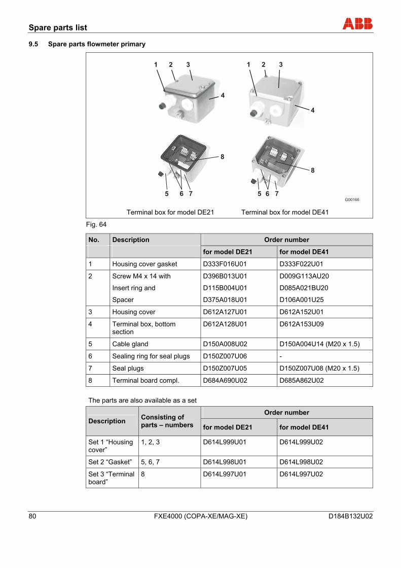
Spare parts list
80 FXE4000 (COPA-XE/MAG-XE) D184B132U02
9.5 Spare parts flowmeter primary
G00166
1 3
5
2
4
8
6 7 5
8
6 7
1 32
4
Terminal box for model DE21 Terminal box for model DE41
Fig. 64
No. Description Order number
for model DE21 for model DE41
1 Housing cover gasket D333F016U01 D333F022U01
2 Screw M4 x 14 with
Insert ring and
Spacer
D396B013U01
D115B004U01
D375A018U01
D009G113AU20
D085A021BU20
D106A001U25
3 Housing cover D612A127U01 D612A152U01
4 Terminal box, bottom section
D612A128U01 D612A153U09
5 Cable gland D150A008U02 D150A004U14 (M20 x 1.5)
6 Sealing ring for seal plugs D150Z007U06 -
7 Seal plugs D150Z007U05 D150Z007U08 (M20 x 1.5)
8 Terminal board compl. D684A690U02 D685A862U02
The parts are also available as a set
Order number Description Consisting of
parts – numbers for model DE21 for model DE41
Set 1 “Housing cover”
1, 2, 3 D614L999U01 D614L999U02
Set 2 “Gasket” 5, 6, 7 D614L998U01 D614L998U02
Set 3 “Terminal board”
8 D614L997U01 D614L997U02
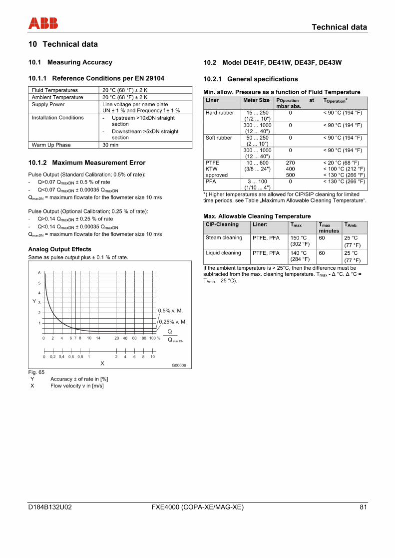
Technical data
D184B132U02 FXE4000 (COPA-XE/MAG-XE) 81
10 Technical data Wechsel ein-auf zweispaltig
10.1 Measuring Accuracy
10.1.1 Reference Conditions per EN 29104
Fluid Temperatures 20 °C (68 °F) ± 2 K Ambient Temperature 20 °C (68 °F) ± 2 K Supply Power Line voltage per name plate
UN ± 1 % and Frequency f ± 1 % Installation Conditions - Upstream >10xDN straight
section - Downstream >5xDN straight
section Warm Up Phase 30 min
10.1.2 Maximum Measurement Error
Pulse Output (Standard Calibration; 0.5% of rate): - Q>0.07 QmaxDN ± 0.5 % of rate - Q<0.07 QmaxDN ± 0.00035 QmaxDN QmaxDN = maximum flowrate for the flowmeter size 10 m/s Pulse Output (Optional Calibration; 0.25 % of rate): - Q>0.14 QmaxDN ± 0.25 % of rate - Q<0.14 QmaxDN ± 0.00035 QmaxDN QmaxDN = maximum flowrate for the flowmeter size 10 m/s Analog Output Effects Same as pulse output plus ± 0.1 % of rate.
Q
Q max DN
0 0,2 0,4 0,6 0,8 1 4 6 8 10
6
5
4
3
2
1
0 2 4 6 7 8 10 14 20 40 60 80 100 %
2
Y
X
0,5% v. M.
0,25% v. M.
G00006
Fig. 65 Y Accuracy ± of rate in [%] X Flow velocity v in [m/s]
10.2 Model DE41F, DE41W, DE43F, DE43W
10.2.1 General specifications
Min. allow. Pressure as a function of Fluid Temperature Liner Meter Size POperation
mbar abs. at TOperation*
15 ... 250 (1/2 ... 10")
0 < 90 °C (194 °F) Hard rubber
300 ... 1000(12 ... 40")
0 < 90 °C (194 °F)
50 ... 250 (2 ... 10")
0 < 90 °C (194 °F) Soft rubber
300 ... 1000(12 ... 40")
0 < 90 °C (194 °F)
PTFE KTW approved
10 ... 600 (3/8 ... 24")
270 400 500
< 20 °C (68 °F) < 100 °C (212 °F)< 130 °C (266 °F)
PFA 3 ... 100 (1/10 ... 4")
0 < 130 °C (266 °F)
*) Higher temperatures are allowed for CIP/SIP cleaning for limited time periods, see Table „Maximum Allowable Cleaning Temperature“. Max. Allowable Cleaning Temperature CIP-Cleaning Liner: Tmax Tmax
minutesTAmb.
Steam cleaning PTFE, PFA 150 °C (302 °F)
60 25 °C (77 °F)
Liquid cleaning PTFE, PFA 140 °C (284 °F)
60 25 °C (77 °F)
If the ambient temperature is > 25°C, then the difference must be subtracted from the max. cleaning temperature. Tmax - Δ °C. Δ °C = TAmb. - 25 °C).
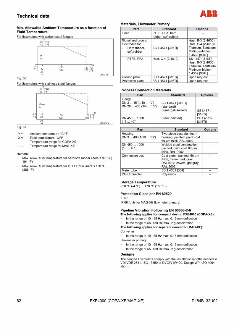
Technical data
82 FXE4000 (COPA-XE/MAG-XE) D184B132U02
Min. Allowable Ambient Temperature as a function of Fluid Temperature For flowmeters with carbon steel flanges
60 [°C]140 [°F]
2577
032
-20-4
50122
X
Y
G00031
130 [°C]266 [°F]
-1014
Fig. 66
For flowmeters with stainless steel flanges 60 [°C]
140 [°F]
2577
-20-4
X
Y
G00045
032
50122
130 [°C]266 [°F]
-25-13
Fig. 67
Y = Ambient temperature °C/°F X = Fluid temperature °C/°F
Temperature range for COPA-XE ------ Temperature range for MAG-XE
Remark: • Max. allow. fluid temperature for hard/soft rubber liners ≤ 90 °C (
194 °F) • Max. allow. fluid temperature for PTFE/ PFA liners ≤ 130 °C
(266 °F)
Materials, Flowmeter Primary Part Standard Options
Liner PTFE, PFA, hard rubber, soft rubber
–
Signal and ground electrodes for
- Hard rubber, soft rubber
SS 1.4571 [316Ti]
Hast. B-3 (2.4600), Hast. C-4 (2.4610) , Titanium, Tantalum, Platinum-Iridium, 1.4539 [904L]
- PTFE, PFA Hast. C-4 (2.4610) SS1.4571[316Ti] Hast. B-3 (2.4600) Titanium, Tantalum, Platinum-Iridium, 1.4539 [904L]
Ground plate SS 1.4571 [316Ti] Upon request Protection plate SS 1.4571 [316Ti] Upon request
Process Connection Materials Part Standard Options
Flange DN 3 ... 15 (1/10 ... ½") DN 20 ... 400 (3/4 ... 16")
SS 1.4571 [316Ti] (standard) Steel (galvanized)
SS1.4571-[316Ti]
DN 450 ... 1000 (18 ... 40")
Steel (painted) SS1.4571-[316Ti]
Part Standard Options
Housing DN 3 ... 400(1/10 ... 16")
Two-piece cast aluminum housing, painted, paint coat 60 µm thick, RAL 9002
–
DN 450 ... 1000 (18 ... 40")
Welded steel construction, painted, paint coat 60 µm thick, RAL 9002
–
Connection box Cast alum., painted, 60 µm thick, frame: dark gray, RAL7012, cover: light gray, RAL 9002
–
Meter tube SS 1.4301 [304] – PG-Connector Polyamide –
Storage Temperature - 20 °C (-4 °F) ... +70 °C (158 °F) Protection Class per EN 60529 IP 67 IP 68 (only for MAG-XE flowmeter primary) Pipeline Vibration Following EN 60068-2-6 The following applies for compact design FXE4000 (COPA-XE): • In the range of 10 - 55 Hz max. 0.15 mm deflection • In the range of 55 -150 Hz max. 2 g acceleration The following applies for separate converter (MAG-XE): Converter • In the range of 10 - 55 Hz max. 0.15 mm deflection Flowmeter primary • In the range of 10 - 55 Hz max. 0.15 mm deflection • In the range of 55 -150 Hz max. 2 g acceleration
Designs The flanged flowmeters comply with the installation lengths defined in VDI/VDE 2641, ISO 13359 or DVGW (W420, Design WP, ISO 4064 short).
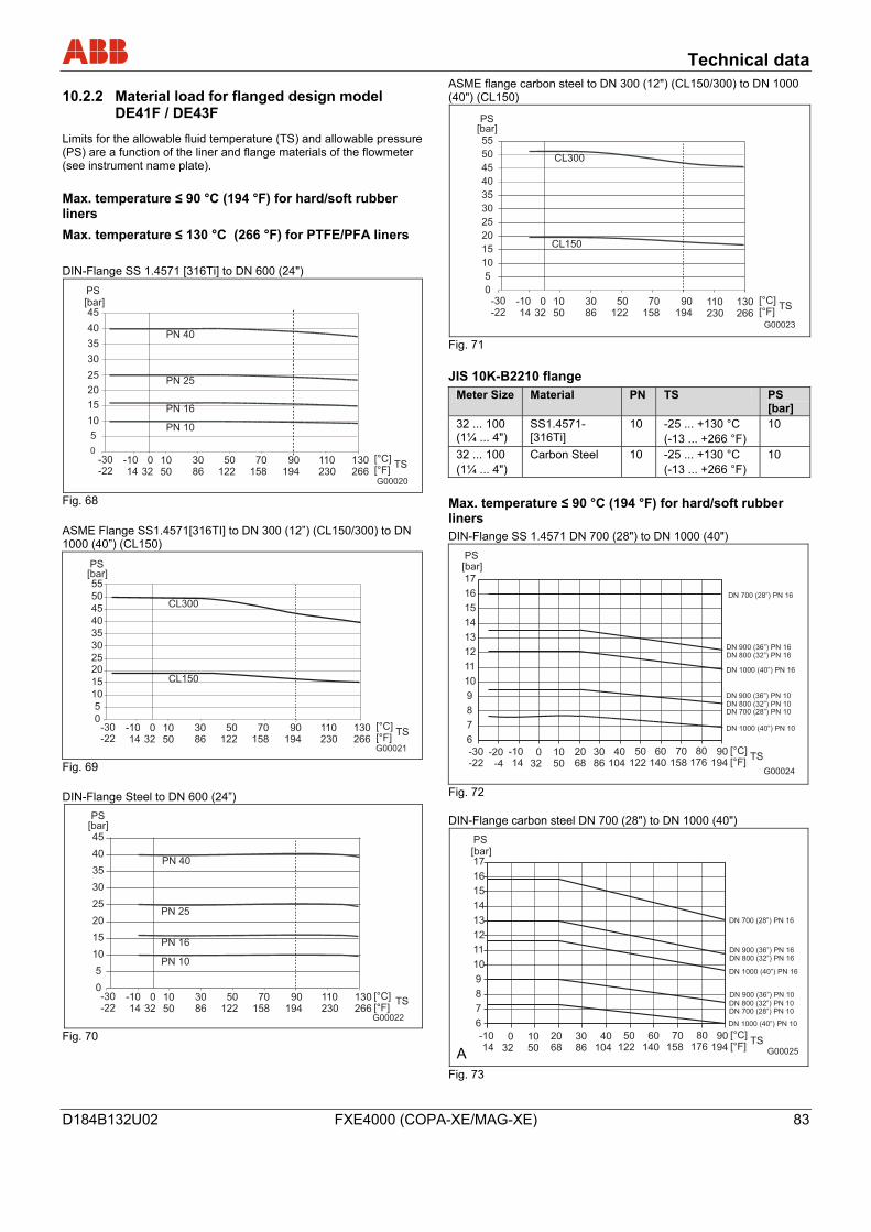
Technical data
D184B132U02 FXE4000 (COPA-XE/MAG-XE) 83
10.2.2 Material load for flanged design model DE41F / DE43F
Limits for the allowable fluid temperature (TS) and allowable pressure (PS) are a function of the liner and flange materials of the flowmeter (see instrument name plate). Max. temperature ≤ 90 °C (194 °F) for hard/soft rubber liners Max. temperature ≤ 130 °C (266 °F) for PTFE/PFA liners DIN-Flange SS 1.4571 [316Ti] to DN 600 (24")
[°C][°F]
[bar]
PN 40
PN 25
PN 16
PN 10
G00020
0
5
10
15
20
25
30
35
40
45
-30-22
-1014
1050
032
3086
50122
70158
90194
110230
130266
TS
PS
Fig. 68 ASME Flange SS1.4571[316TI] to DN 300 (12”) (CL150/300) to DN 1000 (40”) (CL150)
[bar]
G00021
CL300
CL150
0
5
10
15
2025
30
35
40
45
50
55
[°C][°F]
-30-22
-1014
1050
032
3086
50122
70158
90194
110230
130266
TS
PS
Fig. 69 DIN-Flange Steel to DN 600 (24”)
G00022
PN 40
PN 25
PN 16
PN 10
0
5
10
15
20
25
30
35
40
45[bar]
[°C][°F]
-30-22
-1014
1050
032
3086
50122
70158
90194
110230
130266
TS
PS
Fig. 70
ASME flange carbon steel to DN 300 (12") (CL150/300) to DN 1000 (40") (CL150)
G00023
[bar]
CL300
CL150
0
5
10
15
20
25
30
35
40
45
50
55
PS
[°C][°F]
-30-22
-1014
1050
032
3086
50122
70158
90194
110230
130266
TS
Fig. 71 JIS 10K-B2210 flange
Meter Size Material PN TS PS [bar]
32 ... 100 (1¼ ... 4")
SS1.4571-[316Ti]
10 -25 ... +130 °C (-13 ... +266 °F)
10
32 ... 100 (1¼ ... 4")
Carbon Steel 10 -25 ... +130 °C (-13 ... +266 °F)
10
Max. temperature ≤ 90 °C (194 °F) for hard/soft rubber liners DIN-Flange SS 1.4571 DN 700 (28") to DN 1000 (40")
G00024
[bar]
6
7
8
9
10
11
12
13
14
15
16
17
DN 700 (28”) PN 16
DN 900 (36”) PN 16DN 800 (32”) PN 16
DN 1000 (40”) PN 16
DN 900 (36”) PN 10DN 800 (32”) PN 10DN 700 (28”) PN 10
DN 1000 (40”) PN 10
[°C][°F]
-30-22
-20-4
-1014
3086
032
2068
50122
40104
60140
80176
1050
70158
90194
TS
PS
Fig. 72 DIN-Flange carbon steel DN 700 (28") to DN 1000 (40")
AFig. 73
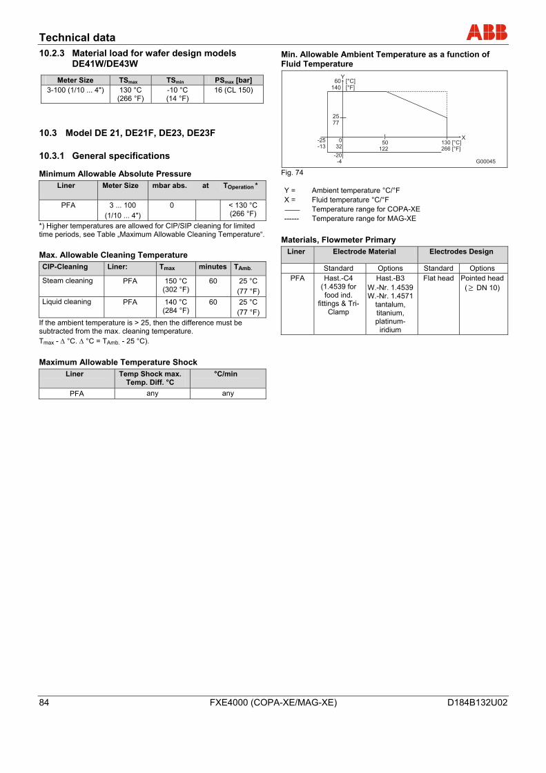
Technical data
84 FXE4000 (COPA-XE/MAG-XE) D184B132U02
10.2.3 Material load for wafer design models DE41W/DE43W
Meter Size TSmax TSmin PSmax [bar] 3-100 (1/10 ... 4") 130 °C
(266 °F) -10 °C (14 °F)
16 (CL 150)
10.3 Model DE 21, DE21F, DE23, DE23F
10.3.1 General specifications
Minimum Allowable Absolute Pressure Liner Meter Size mbar abs. at TOperation *
PFA 3 ... 100 (1/10 ... 4")
0 < 130 °C (266 °F)
*) Higher temperatures are allowed for CIP/SIP cleaning for limited time periods, see Table „Maximum Allowable Cleaning Temperature“. Max. Allowable Cleaning Temperature CIP-Cleaning Liner: Tmax minutes TAmb.
Steam cleaning PFA 150 °C (302 °F)
60 25 °C (77 °F)
Liquid cleaning PFA 140 °C (284 °F)
60 25 °C (77 °F)
If the ambient temperature is > 25, then the difference must be subtracted from the max. cleaning temperature. Tmax - Δ °C. Δ °C = TAmb. - 25 °C). Maximum Allowable Temperature Shock
Liner Temp Shock max. Temp. Diff. °C
°C/min
PFA any any
Min. Allowable Ambient Temperature as a function of Fluid Temperature
60 [°C]140 [°F]
2577
-20-4
X
Y
G00045
032
50122
130 [°C]266 [°F]
-25-13
Fig. 74 Y = Ambient temperature °C/°F X = Fluid temperature °C/°F
Temperature range for COPA-XE ------ Temperature range for MAG-XE
Materials, Flowmeter Primary Liner Electrode Material Electrodes Design
Standard Options Standard Options PFA Hast.-C4
(1.4539 for food ind.
fittings & Tri-Clamp
Hast.-B3 W.-Nr. 1.4539 W.-Nr. 1.4571
tantalum, titanium, platinum-
iridium
Flat head Pointed head( ≥ DN 10)
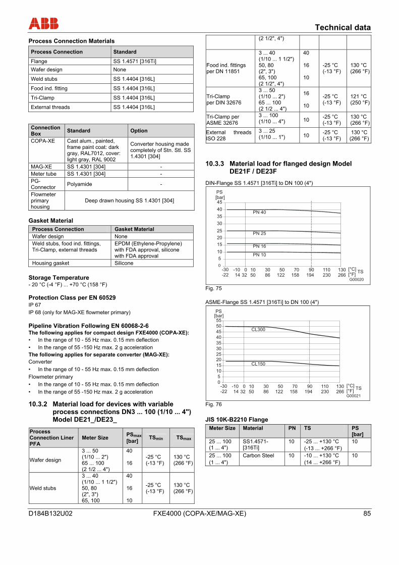
Technical data
D184B132U02 FXE4000 (COPA-XE/MAG-XE) 85
Process Connection Materials
Process Connection Standard
Flange SS 1.4571 [316Ti] Wafer design None
Weld stubs SS 1.4404 [316L]
Food ind. fitting SS 1.4404 [316L]
Tri-Clamp SS 1.4404 [316L]
External threads SS 1.4404 [316L]
Connection Box Standard Option
COPA-XE Cast alum., painted, frame paint coat: dark gray, RAL7012, cover: light gray, RAL 9002
Converter housing made completely of Stn. Stl. SS 1.4301 [304]
MAG-XE SS 1.4301 [304] - Meter tube SS 1.4301 [304] - PG-Connector Polyamide -
Flowmeter primary housing
Deep drawn housing SS 1.4301 [304]
Gasket Material Process Connection Gasket Material Wafer design None Weld stubs, food ind. fittings, Tri-Clamp, external threads
EPDM (Ethylene-Propylene) with FDA approval, silicone with FDA approval
Housing gasket Silicone
Storage Temperature - 20 °C (-4 °F) ... +70 °C (158 °F) Protection Class per EN 60529 IP 67 IP 68 (only for MAG-XE flowmeter primary) Pipeline Vibration Following EN 60068-2-6 The following applies for compact design FXE4000 (COPA-XE): • In the range of 10 - 55 Hz max. 0.15 mm deflection • In the range of 55 -150 Hz max. 2 g acceleration The following applies for separate converter (MAG-XE): Converter • In the range of 10 - 55 Hz max. 0.15 mm deflection Flowmeter primary • In the range of 10 - 55 Hz max. 0.15 mm deflection • In the range of 55 -150 Hz max. 2 g acceleration
10.3.2 Material load for devices with variable process connections DN3 ... 100 (1/10 ... 4") Model DE21_/DE23_
Process Connection Liner PFA
Meter Size PSmax [bar] TSmin TSmax
Wafer design
3 ... 50 (1/10 ... 2") 65 ... 100 (2 1/2 ... 4")
40 16
-25 °C (-13 °F)
130 °C (266 °F)
Weld stubs
3 ... 40 (1/10 ... 1 1/2") 50, 80 (2", 3") 65, 100
40 16 10
-25 °C (-13 °F)
130 °C (266 °F)
(2 1/2", 4")
Food ind. fittings per DN 11851
3 ... 40 (1/10 ... 1 1/2") 50, 80 (2", 3") 65, 100 (2 1/2", 4")
40 16 10
-25 °C (-13 °F)
130 °C (266 °F)
Tri-Clamp per DIN 32676
3 ... 50 (1/10 ... 2") 65 ... 100 (2 1/2 ... 4")
16 10
-25 °C (-13 °F)
121 °C (250 °F)
Tri-Clamp per ASME 32676
3 ... 100 (1/10 ... 4") 10 -25 °C
(-13 °F) 130 °C (266 °F)
External threads ISO 228
3 ... 25 (1/10 ... 1") 10 -25 °C
(-13 °F) 130 °C
(266 °F)
10.3.3 Material load for flanged design Model DE21F / DE23F
DIN-Flange SS 1.4571 [316Ti] to DN 100 (4")
[°C][°F]
[bar]
PN 40
PN 25
PN 16
PN 10
G00020
0
5
10
15
20
25
30
35
40
45
-30-22
-1014
1050
032
3086
50122
70158
90194
110230
130266
TS
PS
Fig. 75 ASME-Flange SS 1.4571 [316Ti] to DN 100 (4")
[bar]
G00021
CL300
CL150
0
5
10
15
2025
30
35
40
45
50
55
[°C][°F]
-30-22
-1014
1050
032
3086
50122
70158
90194
110230
130266
TS
PS
Fig. 76 JIS 10K-B2210 Flange
Meter Size Material PN TS PS [bar]
25 ... 100 (1 ... 4")
SS1.4571-[316Ti]
10 -25 ... +130 °C (-13 ... +266 °F)
10
25 ... 100 (1 ... 4")
Carbon Steel 10 -10 ... +130 °C (14 ... +266 °F)
10
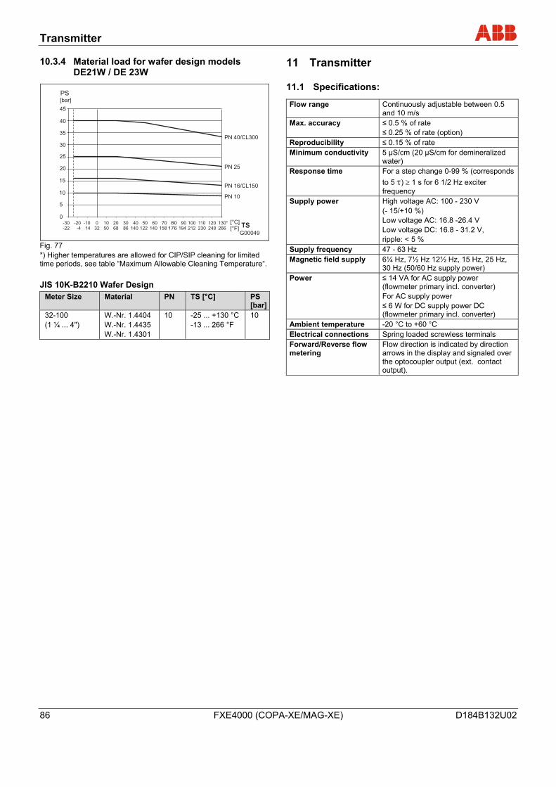
Transmitter
86 FXE4000 (COPA-XE/MAG-XE) D184B132U02
10.3.4 Material load for wafer design models DE21W / DE 23W
G00049
PN 40/CL300
PN 25
PN 16/CL150
PN 10
0
5
10
15
20
25
30
35
40
45
-30-22
-20-4
-1014
032
1050
2068
3086
40140
50122
60140
70158
80176
90194
100212
110230
120248
130*266
[bar]
[°C][°F]
TSTS
PS
Fig. 77 *) Higher temperatures are allowed for CIP/SIP cleaning for limited time periods, see table “Maximum Allowable Cleaning Temperature“. JIS 10K-B2210 Wafer Design
Meter Size Material PN TS [°C] PS [bar]
32-100 (1 ¼ ... 4")
W.-Nr. 1.4404 W.-Nr. 1.4435 W.-Nr. 1.4301
10 -25 ... +130 °C -13 ... 266 °F
10
11 Transmitter
11.1 Specifications:
Flow range Continuously adjustable between 0.5 and 10 m/s
Max. accuracy ≤ 0.5 % of rate ≤ 0.25 % of rate (option)
Reproducibility ≤ 0.15 % of rate Minimum conductivity 5 µS/cm (20 µS/cm for demineralized
water) Response time For a step change 0-99 % (corresponds
to 5 τ) ≥ 1 s for 6 1/2 Hz exciter frequency
Supply power High voltage AC: 100 - 230 V (- 15/+10 %) Low voltage AC: 16.8 -26.4 V Low voltage DC: 16.8 - 31.2 V, ripple: < 5 %
Supply frequency 47 - 63 Hz Magnetic field supply 6¼ Hz, 7½ Hz 12½ Hz, 15 Hz, 25 Hz,
30 Hz (50/60 Hz supply power) Power ≤ 14 VA for AC supply power
(flowmeter primary incl. converter) For AC supply power ≤ 6 W for DC supply power DC (flowmeter primary incl. converter)
Ambient temperature -20 °C to +60 °C Electrical connections Spring loaded screwless terminals Forward/Reverse flow metering
Flow direction is indicated by direction arrows in the display and signaled over the optocoupler output (ext. contact output).
Transmitter
D184B132U02 FXE4000 (COPA-XE/MAG-XE) 87
11.2 Housing Variants
COPA XE Compact design with converter housing made of cast light metal, painted, paint coat 60 µm thick, rear section RAL 7012 dark gray, front section (cover) RAL 9002 light gray Option Converter housing made of stainless steel [304] MAG-XE • Field mount housing made of cast light metal, painted, paint coat
60 µm thick, rear section RAL 7012 dark gray, front section (cover) RAL 9002 light gray
• Panel installation housing • Housing for rail mounting
Weight COPA-XE: see Data Sheet MAG-XE (converter): • Field mount housing: 4.5 kg • Rail mount housing: 1.2 kg • Panel installation housing 1.2 kg Signal Cable (only for MAG-XE) Max. cable length between flowmeter primary and converter: 50 m. Scope of delivery: 10 m. If more than 10 m is required, the cable can be ordered under the order number D173D025U01.
Wechsel ein-auf zweispaltig
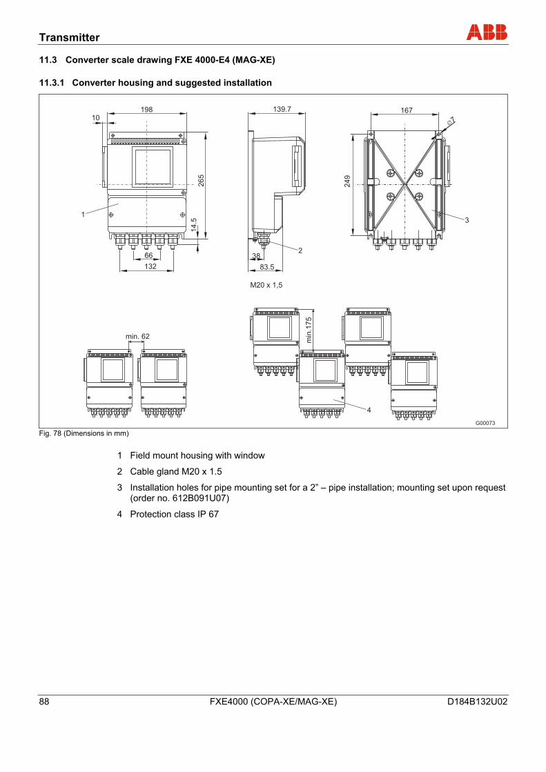
Transmitter
88 FXE4000 (COPA-XE/MAG-XE) D184B132U02
11.3 Converter scale drawing FXE 4000-E4 (MAG-XE)
11.3.1 Converter housing and suggested installation
G00073
min
.17
5
min. 62
249
167
7
38
83.5
139.7
66
265
14.5
M20 x 1,5
19810
132
1
2
3
4
Fig. 78 (Dimensions in mm)
1 Field mount housing with window
2 Cable gland M20 x 1.5
3 Installation holes for pipe mounting set for a 2” – pipe installation; mounting set upon request (order no. 612B091U07)
4 Protection class IP 67
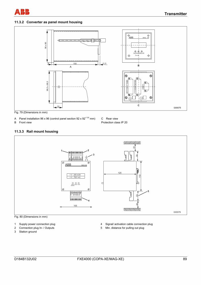
Transmitter
D184B132U02 FXE4000 (COPA-XE/MAG-XE) 89
11.3.2 Converter as panel mount housing
ABB
AB
C
8 11,5155
96
x96
MAG - XE
DATASTEPC/CE
ENTER
1S
12
2S
3M
2M
1
-+
X1
G2
P7
62
V8
V9
NP
EL
98,5
x98,5
32G00075
Fig. 79 (Dimensions in mm)
A Panel installation 96 x 96 (control panel section 92 x 92+ 0,8 mm) B Front view
C Rear view Protection class IP 20
11.3.3 Rail mount housing
G00076 Fig. 80 (Dimensions in mm)
1 Supply power connection plug 2 Connection plug In- / Outputs 3 Station ground
4 Signal/ activation cable connection plug 5 Min. distance for pulling out plug
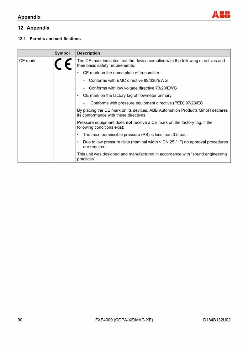
Appendix
90 FXE4000 (COPA-XE/MAG-XE) D184B132U02
12 Appendix
12.1 Permits and certifications
Symbol Description
CE mark
The CE mark indicates that the device complies with the following directives and their basic safety requirements:
• CE mark on the name plate of transmitter
− Conforms with EMC directive 89/336/EWG
− Conforms with low voltage directive 73/23/EWG
• CE mark on the factory tag of flowmeter primary
− Conforms with pressure equipment directive (PED) 97/23/EC
By placing the CE mark on its devices, ABB Automation Products GmbH declares its conformance with these directives.
Pressure equipment does not receive a CE mark on the factory tag, if the following conditions exist:
• The max. permissible pressure (PS) is less than 0.5 bar.
• Due to low pressure risks (nominal width ≤ DN 25 / 1") no approval procedures are required.
This unit was designed and manufactured in accordance with “sound engineering practices”.
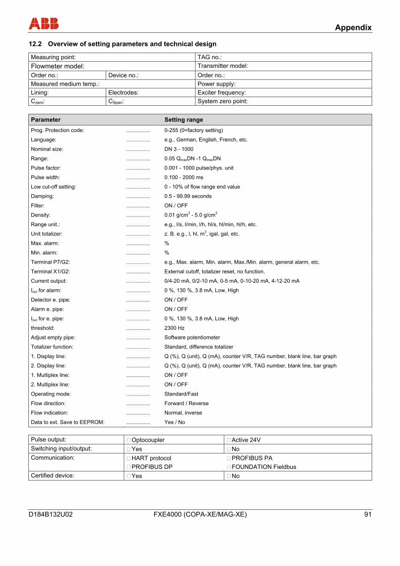
Appendix
D184B132U02 FXE4000 (COPA-XE/MAG-XE) 91
12.2 Overview of setting parameters and technical design
Measuring point: TAG no.: Flowmeter model: Transmitter model: Order no.: Device no.: Order no.: Measured medium temp.: Power supply: Lining: Electrodes: Exciter frequency: Czero: CSpan: System zero point:
Parameter Setting range
Prog. Protection code: ................ 0-255 (0=factory setting)
Language: ................ e.g., German, English, French, etc.
Nominal size: ................ DN 3 - 1000
Range: ................ 0.05 QmaxDN -1 QmaxDN
Pulse factor: ................ 0.001 - 1000 pulse/phys. unit
Pulse width: ................ 0.100 - 2000 ms
Low cut-off setting: ................ 0 - 10% of flow range end value
Damping: ................ 0.5 - 99.99 seconds
Filter: ................ ON / OFF
Density: ................ 0.01 g/cm3 - 5.0 g/cm3
Range unit.: ................ e.g., l/s, l/min, l/h, hl/s, hl/min, hl/h, etc.
Unit totalizer: ................ z. B. e.g., l, hl, m3, igal, gal, etc. Max. alarm: ................ %
Min. alarm: ................ %
Terminal P7/G2: ................ e.g., Max. alarm, Min. alarm, Max./Min. alarm, general alarm, etc.
Terminal X1/G2: ................ External cutoff, totalizer reset, no function.
Current output: ................ 0/4-20 mA, 0/2-10 mA, 0-5 mA, 0-10-20 mA, 4-12-20 mA
Iout for alarm: ................ 0 %, 130 %, 3.8 mA, Low, High
Detector e. pipe: ................ ON / OFF
Alarm e. pipe: ................ ON / OFF
Iout for e. pipe: ................ 0 %, 130 %, 3.8 mA, Low, High
threshold: ................ 2300 Hz
Adjust empty pipe: ................ Software potentiometer
Totalizer function: ................ Standard, difference totalizer
1. Display line: ................ Q (%), Q (unit), Q (mA), counter V/R, TAG number, blank line, bar graph
2. Display line: ................ Q (%), Q (unit), Q (mA), counter V/R, TAG number, blank line, bar graph
1. Multiplex line: ................ ON / OFF
2. Multiplex line: ................ ON / OFF
Operating mode: ................ Standard/Fast
Flow direction: ................ Forward / Reverse
Flow indication: ................ Normal, inverse
Data to ext. Save to EEPROM: ................ Yes / No
Pulse output: Optocoupler Active 24V Switching input/output: Yes No Communication: HART protocol
PROFIBUS DP PROFIBUS PA FOUNDATION Fieldbus
Certified device: Yes No

Appendix
92 FXE4000 (COPA-XE/MAG-XE) D184B132U02
Statement about the contamination of devices and components
The repair and/or maintenance of devices and components will only be performed when a completely filled out explanation is present.
Otherwise, the shipment can be rejected. This explanation may only be filled out and signed by authorized specialist personnel of the operator.
Customer details:
Company:
Address:
Contact person: Telephone:
Fax: E-Mail:
Device details:
Type: Serial no.:
Reason for the return/description of the defect:
Was this device used for working with substances which pose a threat or health risk?
Yes No
If yes, which type of contamination (please place an X next to the applicable items)
biological corrosive/irritating combustible (highly/extremely combustible)
toxic explosive other toxic substances
radioactive
Which substances have had contact with the device?
1.
2.
3.
We hereby certify that the devices/parts shipped were cleaned and are free from any dangerous or poisonous materials.
City, Date Signature and company stamp

Appendix
D184B132U02 FXE4000 (COPA-XE/MAG-XE) 93
12.3 Additional documents
English-language documents
• Commissioning Instructions (D184B133U02)
• Data Sheet (D841S075U02)
• Interface description for devices with HART communication (D184B108U02)
• Interface description for devices with PROFIBUS DP communication (D184B093U10)
• Interface description for devices with PROFIBUS PA communication (D184B093U26)
• Interface description for devices with PROFIBUS Fieldbus communication (D184B093U18)
Index
94 FXE4000 (COPA-XE/MAG-XE) D184B132U02
13 Index Wechsel ein-auf zweispaltig
A
Additional documents ..............................................93
Appendix ..................................................................90
Approved measurement mediums.............................9
B
Builder's plate ..........................................................12
C
Checks .....................................................................46
Commissioning FOUNDATION FIELDBUS units ....55
Commissioning PROFIBUS PA units ......................50
Commissioning the unit ...........................................48
Connection for protection class IP68.......................36
COPA-XE.................................................................16
D
Data entry ................................................................58
Design......................................................................16
Design and function .................................................15
Device designs.........................................................16
Display options.........................................................57
Display rotation ........................................................28
E
Electrical connection................................................32
Electrical installation safety information...................14
Error messages........................................................72
Excitation cable........................................................35
F
Factory Tag..............................................................10
Flowmeter primary ...................................................74
Fuse COPA-XE........................................................76
FXE4000 (COPA-XE), analog communication (incl. HART) ..................................................................39
FXE4000 (COPA-XE), digital communication .........40
FXE4000 (MAG-XE), digital communication ...........42
FXE4000 MAG-XE, analog communication (incl. HART) ..................................................................41
G
Gaskets..............................................................26, 75
General information on ground connections............29
General information on transport .............................18
General Safety Information........................................7
Ground .....................................................................29
Ground for devices with protective plate .................31
Ground for stainless steel model DE 21 and DE 2331
Ground for units with hard or soft rubber liners .......31
Ground with conductive PTFE grounding plate .......31
H
Housing rotation.......................................................28
I
Improper use..............................................................8
In- and outlet pipe sections......................................20
Information on voltage/current consumption ...........53
Inspection.................................................................18
Installation..........................................................20, 23
Intended use ..............................................................7
Interconnection Diagrams........................................39
Interconnection examples for the peripherals with analog communication (incl. HART).....................43
Interconnection examples for the peripherals with digital communication...........................................44
L
Labels and symbols ...................................................9
M
MAG-XE...................................................................17
Maintenance / Repair...............................................74
Maintenance safety information...............................14
Measuring principle..................................................15
Mounting the measuring tube ..................................26
N
Name Plate ........................................................10, 11
Non-metallic pipes ...................................................30
O
Operating safety information....................................14
Operating the terminals ...........................................32
Operator liability .......................................................13
P
Parameter description..............................................61
Parameterization......................................................57
Permits and certifications.........................................90
Index
D184B132U02 FXE4000 (COPA-XE/MAG-XE) 95
Personnel qualification.............................................13
Pipes with insulating liner ........................................30
Potting the connection box ......................................37
Protective plates ......................................................26
R
Replacing the transmitter.........................................75
Returning devices ....................................................13
S
Safety.........................................................................7
Signal cable .............................................................35
Spare parts COPA-XE .......................................76, 77
Spare parts flowmeter primary.................................80
Spare parts list .........................................................76
Spare parts transmitter E4.......................................78
Start-up ....................................................................46
Supports...................................................................23
Symbols and warnings...............................................9
System integration ...................................................53
T
Technical data..........................................................81
Technical limit values.................................................8
Torque information...................................................27
Transmitter...............................................................86
Transport..................................................................18
Transport of flanged units ≥ DN 400........................19
Transport safety information ....................................13
W
Warranty provision.....................................................9
Wechsel ein-auf zweispaltig A
ABB has Sales & Customer Support expertise in over 100 countries worldwide. www.abb.com/flow
The Company’s policy is one of continuous productimprovement and the right is reserved to modify the
information contained herein without notice.
Printed in the Fed. Rep. of Germany (07.2006)
© ABB 2006
D18
4B13
2U02
ABB Limited Oldends Lane, Stonehouse Gloucestershire, GL10 3TA UK Tel: +44 (0)1453 826661 Fax: +44 (0)1453 829671
ABB Inc. 125 E. County Line Road Warminster, PA 18974 USA Tel: +1 215 674 6000 Fax: +1 215 674 7183
ABB Automation Products GmbH Dransfelder Str. 2 37079 Goettingen Germany Tel: +49 551 905-534 Fax: +49 551 905-555 [email protected]