Embed Size (px)
Citation preview
Operating Instructions
Exicom Eagle ET-306, ET-316, ET-336 (valid for Hardware Revision 1.xx)
R. STAHL HMI Systems GmbH
Im Gewerbegebiet Pesch 14 50767 Köln
Version 1.7E Issue: 14.11.2007
© R. STAHL HMI Systems GmbH / OperatingInstruction_Exicom_Eagle_en_V_1_7_E.doc / 14.11.2007 Page 1 of 52
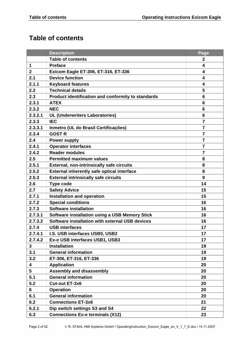
Table of contents Operating Instructions Exicom Eagle
Table of contents Description Page Table of contents 2 1 Preface 4 2 Exicom Eagle ET-306, ET-316, ET-336 4 2.1 Device function 4 2.1.1 Keyboard features 4 2.2 Technical details 5 2.3 Product identification and conformity to standards 6 2.3.1 ATEX 6 2.3.2 NEC 6 2.3.2.1 UL (Underwriters Laboratories) 6 2.3.3 IEC 7 2.3.3.1 Inmetro (UL do Brasil Certificações) 7 2.3.4 GOST R 7 2.4 Power supply 7 2.4.1 Operator interfaces 7 2.4.2 Reader modules 7 2.5 Permitted maximum values 8 2.5.1 External, non-intrinsically safe circuits 8 2.5.2 External inherently safe optical interface 8 2.5.3 External intrinsically safe circuits 9 2.6 Type code 14 2.7 Safety Advice 15 2.7.1 Installation and operation 15 2.7.2 Special conditions 16 2.7.3 Software installation 16 2.7.3.1 Software installation using a USB Memory Stick 16 2.7.3.2 Software installation with external USB devices 16 2.7.4 USB interfaces 17 2.7.4.1 I.S. USB interfaces USB0, USB2 17 2.7.4.2 Ex-e USB interfaces USB1, USB3 17 3 Installation 19 3.1 General information 19 3.2 ET-306, ET-316, ET-336 19 4 Application 20 5 Assembly and disassembly 20 5.1 General information 20 5.2 Cut-out ET-3x6 20 6 Operation 20 6.1 General information 20 6.2 Connections ET-3x6 21 6.2.1 Dip switch settings S3 and S4 22 6.3 Connections Ex-e terminals (X12) 23
Page 2 of 52 © R. STAHL HMI Systems GmbH / OperatingInstruction_Exicom_Eagle_en_V_1_7_E.doc / 14.11.2007
Operating Instructions Exicom Eagle Table of contents
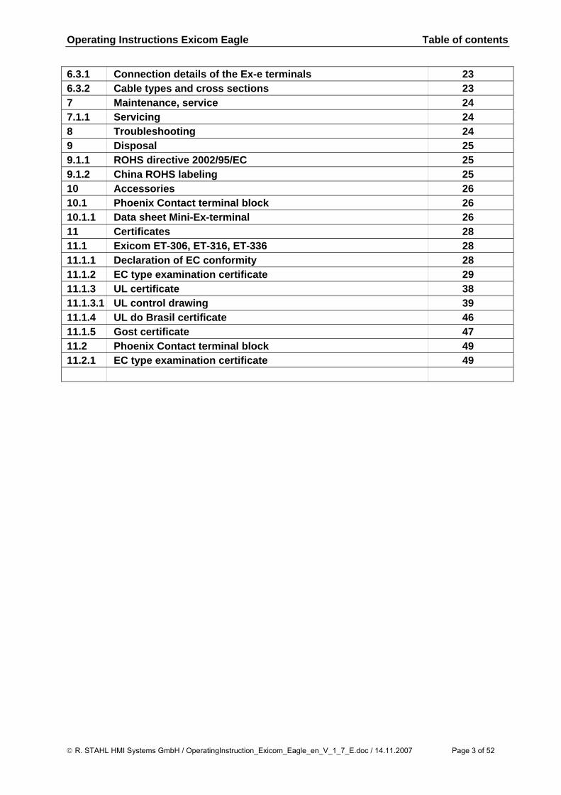
6.3.1 Connection details of the Ex-e terminals 23 6.3.2 Cable types and cross sections 23 7 Maintenance, service 24 7.1.1 Servicing 24 8 Troubleshooting 24 9 Disposal 25 9.1.1 ROHS directive 2002/95/EC 25 9.1.2 China ROHS labeling 25 10 Accessories 26 10.1 Phoenix Contact terminal block 26 10.1.1 Data sheet Mini-Ex-terminal 26 11 Certificates 28 11.1 Exicom ET-306, ET-316, ET-336 28 11.1.1 Declaration of EC conformity 28 11.1.2 EC type examination certificate 29 11.1.3 UL certificate 38 11.1.3.1 UL control drawing 39 11.1.4 UL do Brasil certificate 46 11.1.5 Gost certificate 47 11.2 Phoenix Contact terminal block 49 11.2.1 EC type examination certificate 49
© R. STAHL HMI Systems GmbH / OperatingInstruction_Exicom_Eagle_en_V_1_7_E.doc / 14.11.2007 Page 3 of 52
Preface Operating Instructions Exicom Eagle
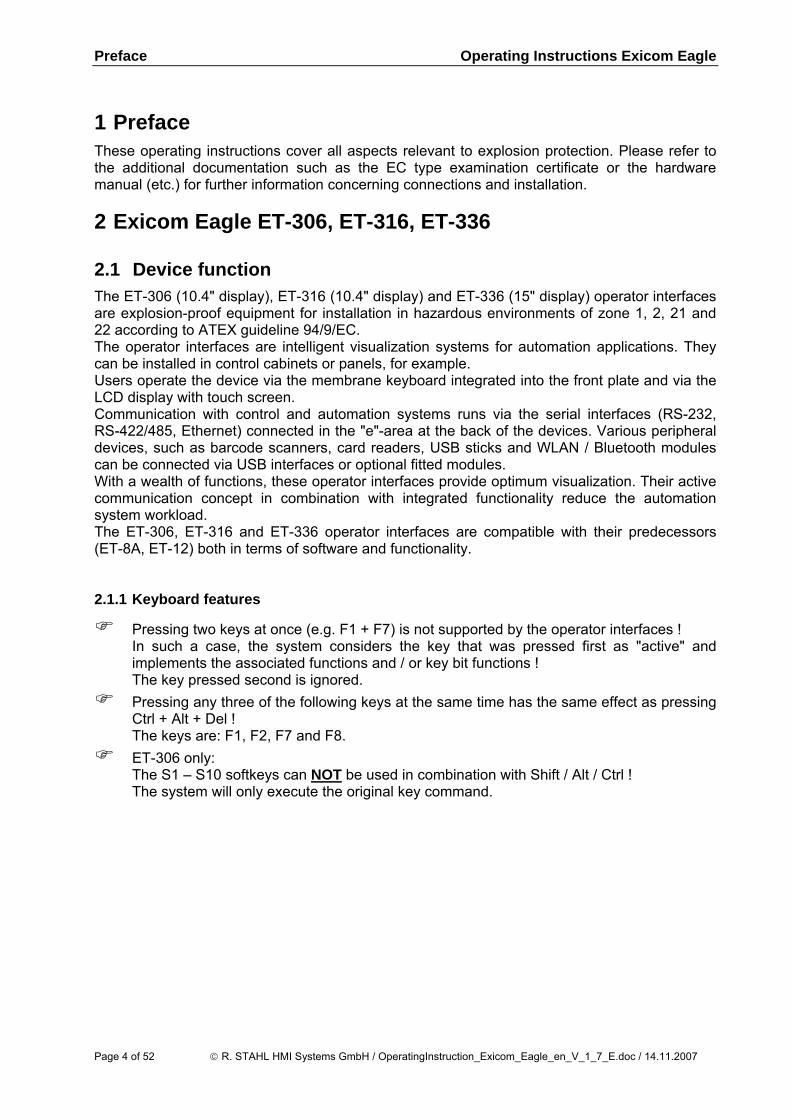
1 Preface These operating instructions cover all aspects relevant to explosion protection. Please refer to the additional documentation such as the EC type examination certificate or the hardware manual (etc.) for further information concerning connections and installation. 2 Exicom Eagle ET-306, ET-316, ET-336 2.1 Device function The ET-306 (10.4" display), ET-316 (10.4" display) and ET-336 (15" display) operator interfaces are explosion-proof equipment for installation in hazardous environments of zone 1, 2, 21 and 22 according to ATEX guideline 94/9/EC. The operator interfaces are intelligent visualization systems for automation applications. They can be installed in control cabinets or panels, for example. Users operate the device via the membrane keyboard integrated into the front plate and via the LCD display with touch screen. Communication with control and automation systems runs via the serial interfaces (RS-232, RS-422/485, Ethernet) connected in the "e"-area at the back of the devices. Various peripheral devices, such as barcode scanners, card readers, USB sticks and WLAN / Bluetooth modules can be connected via USB interfaces or optional fitted modules. With a wealth of functions, these operator interfaces provide optimum visualization. Their active communication concept in combination with integrated functionality reduce the automation system workload. The ET-306, ET-316 and ET-336 operator interfaces are compatible with their predecessors (ET-8A, ET-12) both in terms of software and functionality. 2.1.1 Keyboard features
Pressing two keys at once (e.g. F1 + F7) is not supported by the operator interfaces ! In such a case, the system considers the key that was pressed first as "active" and implements the associated functions and / or key bit functions ! The key pressed second is ignored.
Pressing any three of the following keys at the same time has the same effect as pressing Ctrl + Alt + Del ! The keys are: F1, F2, F7 and F8.
ET-306 only: The S1 – S10 softkeys can NOT be used in combination with Shift / Alt / Ctrl ! The system will only execute the original key command.
Page 4 of 52 © R. STAHL HMI Systems GmbH / OperatingInstruction_Exicom_Eagle_en_V_1_7_E.doc / 14.11.2007
Operating Instructions Exicom Eagle Exicom Eagle ET-306, ET-316, ET-336
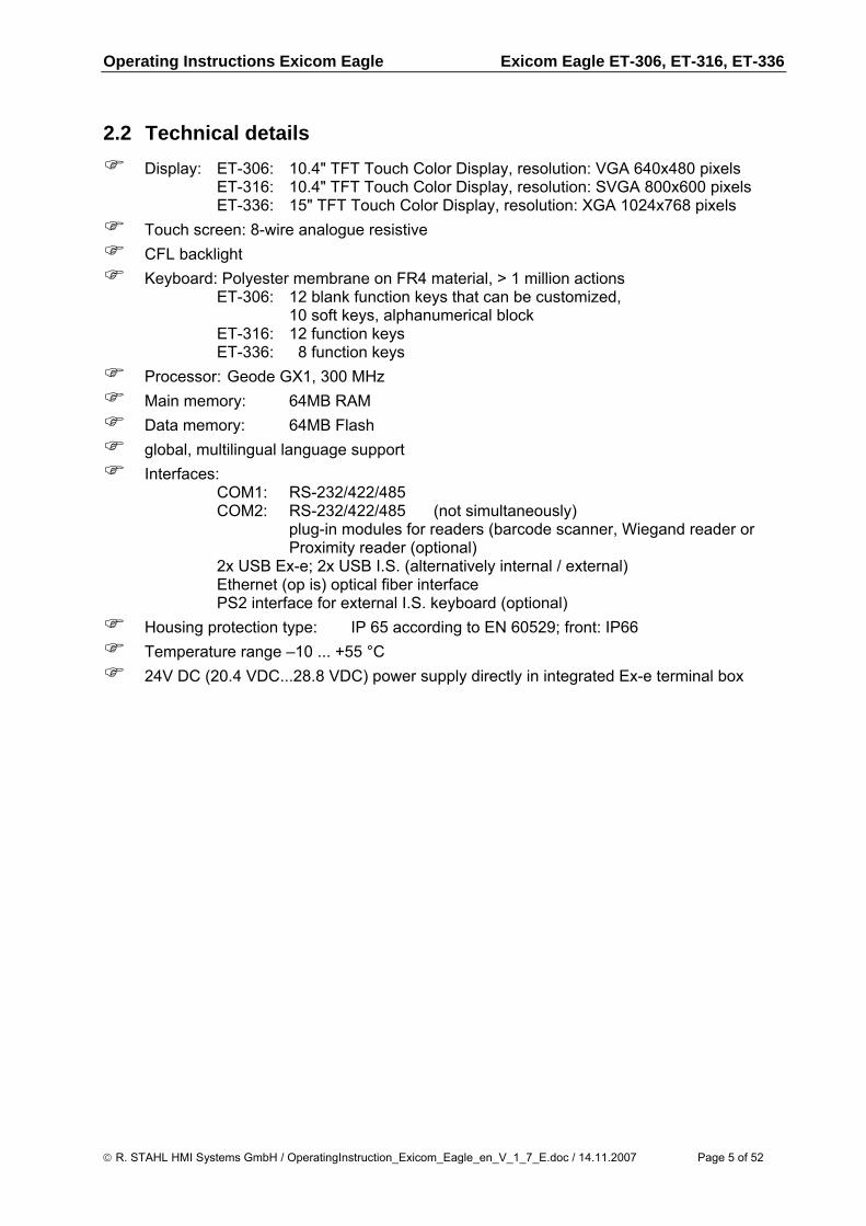
2.2 Technical details
Display: ET-306: 10.4" TFT Touch Color Display, resolution: VGA 640x480 pixels ET-316: 10.4" TFT Touch Color Display, resolution: SVGA 800x600 pixels ET-336: 15" TFT Touch Color Display, resolution: XGA 1024x768 pixels
Touch screen: 8-wire analogue resistive CFL backlight Keyboard: Polyester membrane on FR4 material, > 1 million actions
ET-306: 12 blank function keys that can be customized, 10 soft keys, alphanumerical block
ET-316: 12 function keys ET-336: 8 function keys
Processor: Geode GX1, 300 MHz Main memory: 64MB RAM Data memory: 64MB Flash global, multilingual language support Interfaces:
COM1: RS-232/422/485 COM2: RS-232/422/485 (not simultaneously) plug-in modules for readers (barcode scanner, Wiegand reader or
Proximity reader (optional) 2x USB Ex-e; 2x USB I.S. (alternatively internal / external) Ethernet (op is) optical fiber interface PS2 interface for external I.S. keyboard (optional)
Housing protection type: IP 65 according to EN 60529; front: IP66 Temperature range –10 ... +55 °C 24V DC (20.4 VDC...28.8 VDC) power supply directly in integrated Ex-e terminal box
© R. STAHL HMI Systems GmbH / OperatingInstruction_Exicom_Eagle_en_V_1_7_E.doc / 14.11.2007 Page 5 of 52
Exicom Eagle ET-306, ET-316, ET-336 Operating Instructions Exicom Eagle
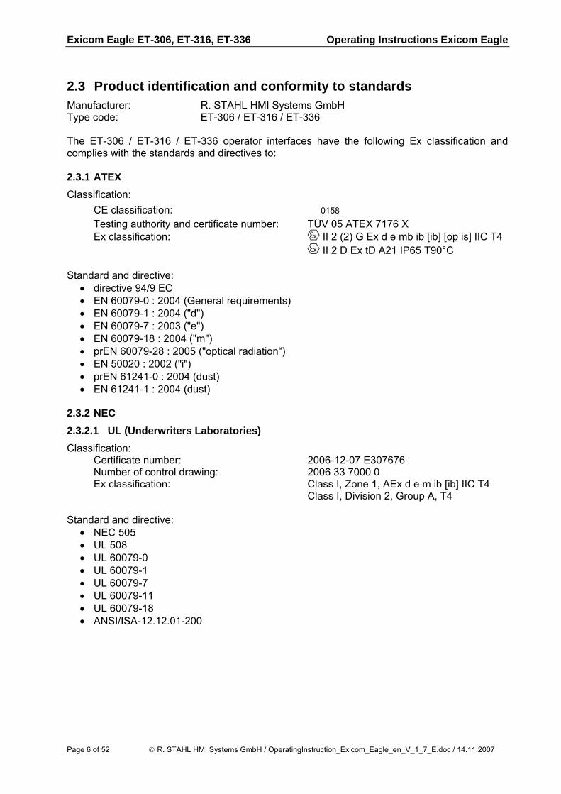
2.3 Product identification and conformity to standards Manufacturer: R. STAHL HMI Systems GmbH Type code: ET-306 / ET-316 / ET-336 The ET-306 / ET-316 / ET-336 operator interfaces have the following Ex classification and complies with the standards and directives to: 2.3.1 ATEX Classification:
CE classification: �0158 Testing authority and certificate number: TÜV 05 ATEX 7176 X Ex classification: e II 2 (2) G Ex d e mb ib [ib] [op is] IIC T4 e II 2 D Ex tD A21 IP65 T90°C
Standard and directive:
• directive 94/9 EC • EN 60079-0 : 2004 (General requirements) • EN 60079-1 : 2004 ("d") • EN 60079-7 : 2003 ("e") • EN 60079-18 : 2004 ("m") • prEN 60079-28 : 2005 ("optical radiation“) • EN 50020 : 2002 ("i") • prEN 61241-0 : 2004 (dust) • EN 61241-1 : 2004 (dust)
2.3.2 NEC 2.3.2.1 UL (Underwriters Laboratories) Classification:
Certificate number: 2006-12-07 E307676 Number of control drawing: 2006 33 7000 0 Ex classification: Class I, Zone 1, AEx d e m ib [ib] IIC T4 Class I, Division 2, Group A, T4
Standard and directive:
• NEC 505 • UL 508 • UL 60079-0 • UL 60079-1 • UL 60079-7 • UL 60079-11 • UL 60079-18 • ANSI/ISA-12.12.01-200
Page 6 of 52 © R. STAHL HMI Systems GmbH / OperatingInstruction_Exicom_Eagle_en_V_1_7_E.doc / 14.11.2007
Operating Instructions Exicom Eagle Exicom Eagle ET-306, ET-316, ET-336
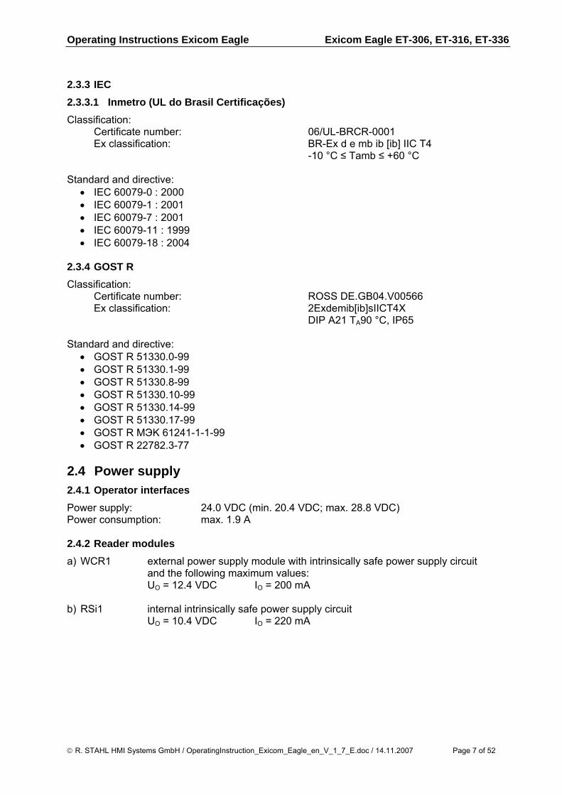
2.3.3 IEC 2.3.3.1 Inmetro (UL do Brasil Certificações) Classification:
Certificate number: 06/UL-BRCR-0001 Ex classification: BR-Ex d e mb ib [ib] IIC T4 -10 °C ≤ Tamb ≤ +60 °C
Standard and directive:
• IEC 60079-0 : 2000 • IEC 60079-1 : 2001 • IEC 60079-7 : 2001 • IEC 60079-11 : 1999 • IEC 60079-18 : 2004
2.3.4 GOST R Classification:
Certificate number: ROSS DE.GB04.V00566 Ex classification: 2Exdemib[ib]sIICT4X DIP A21 TA90 °C, IP65
Standard and directive:
• GOST R 51330.0-99 • GOST R 51330.1-99 • GOST R 51330.8-99 • GOST R 51330.10-99 • GOST R 51330.14-99 • GOST R 51330.17-99 • GOST R MЭK 61241-1-1-99 • GOST R 22782.3-77
2.4 Power supply 2.4.1 Operator interfaces Power supply: 24.0 VDC (min. 20.4 VDC; max. 28.8 VDC) Power consumption: max. 1.9 A 2.4.2 Reader modules a) WCR1 external power supply module with intrinsically safe power supply circuit and the following maximum values: UO = 12.4 VDC IO = 200 mA b) RSi1 internal intrinsically safe power supply circuit UO = 10.4 VDC IO = 220 mA
© R. STAHL HMI Systems GmbH / OperatingInstruction_Exicom_Eagle_en_V_1_7_E.doc / 14.11.2007 Page 7 of 52
Exicom Eagle ET-306, ET-316, ET-336 Operating Instructions Exicom Eagle
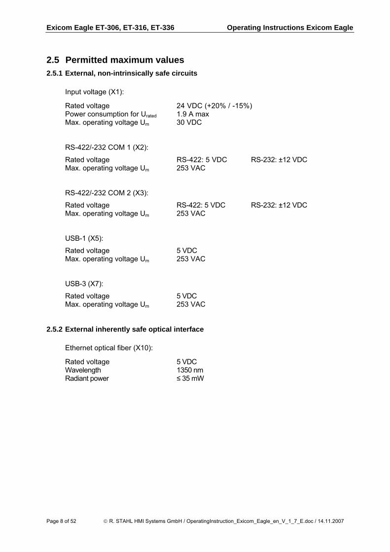
2.5 Permitted maximum values 2.5.1 External, non-intrinsically safe circuits
Input voltage (X1):
Rated voltage 24 VDC (+20% / -15%) Power consumption for Urated 1.9 A max Max. operating voltage Um 30 VDC RS-422/-232 COM 1 (X2):
Rated voltage RS-422: 5 VDC RS-232: ±12 VDC Max. operating voltage Um 253 VAC RS-422/-232 COM 2 (X3):
Rated voltage RS-422: 5 VDC RS-232: ±12 VDC Max. operating voltage Um 253 VAC USB-1 (X5):
Rated voltage 5 VDC Max. operating voltage Um 253 VAC USB-3 (X7):
Rated voltage 5 VDC Max. operating voltage Um 253 VAC
2.5.2 External inherently safe optical interface
Ethernet optical fiber (X10):
Rated voltage 5 VDC Wavelength 1350 nm Radiant power ≤ 35 mW
Page 8 of 52 © R. STAHL HMI Systems GmbH / OperatingInstruction_Exicom_Eagle_en_V_1_7_E.doc / 14.11.2007
Operating Instructions Exicom Eagle Exicom Eagle ET-306, ET-316, ET-336
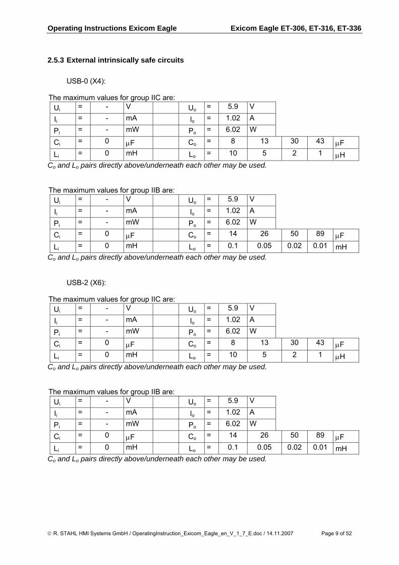
2.5.3 External intrinsically safe circuits
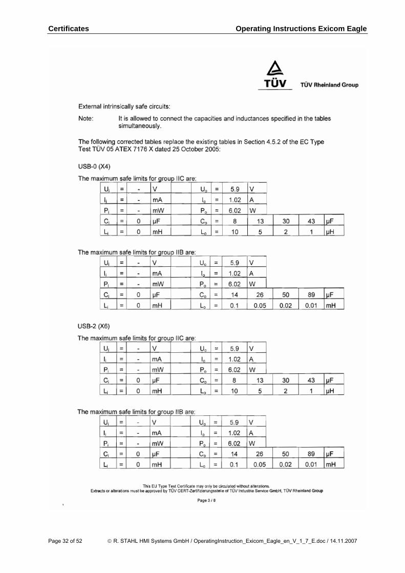
USB-0 (X4):
The maximum values for group IIC are: Ui = - V Uo = 5.9 V
Ii = - mA lo = 1.02 A
Pi = - mW Po = 6.02 W
Ci = 0 μF Co = 8 13 30 43 μF Li = 0 mH Lo = 10 5 2 1 μH
Co and Lo pairs directly above/underneath each other may be used.
The maximum values for group IIB are: Ui = - V Uo = 5.9 V
Ii = - mA lo = 1.02 A
Pi = - mW Po = 6.02 W
Ci = 0 μF Co = 14 26 50 89 μF Li = 0 mH Lo = 0.1 0.05 0.02 0.01 mH
Co and Lo pairs directly above/underneath each other may be used.
USB-2 (X6):
The maximum values for group IIC are: Ui = - V Uo = 5.9 V
Ii = - mA lo = 1.02 A
Pi = - mW Po = 6.02 W
Ci = 0 μF Co = 8 13 30 43 μF Li = 0 mH Lo = 10 5 2 1 μH
Co and Lo pairs directly above/underneath each other may be used.
The maximum values for group IIB are: Ui = - V Uo = 5.9 V
Ii = - mA lo = 1.02 A
Pi = - mW Po = 6.02 W
Ci = 0 μF Co = 14 26 50 89 μF Li = 0 mH Lo = 0.1 0.05 0.02 0.01 mH
Co and Lo pairs directly above/underneath each other may be used.
© R. STAHL HMI Systems GmbH / OperatingInstruction_Exicom_Eagle_en_V_1_7_E.doc / 14.11.2007 Page 9 of 52
Exicom Eagle ET-306, ET-316, ET-336 Operating Instructions Exicom Eagle
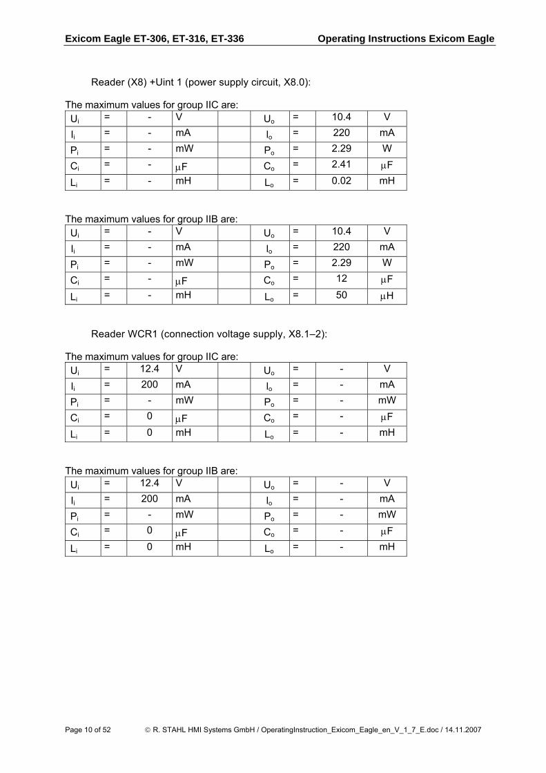
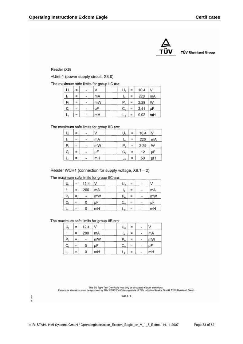
Reader (X8) +Uint 1 (power supply circuit, X8.0):
The maximum values for group IIC are: Ui = - V Uo = 10.4 V
Ii = - mA lo = 220 mA
Pi = - mW Po = 2.29 W
Ci = - μF Co = 2.41 μF
Li = - mH Lo = 0.02 mH
The maximum values for group IIB are: Ui = - V Uo = 10.4 V
Ii = - mA lo = 220 mA
Pi = - mW Po = 2.29 W
Ci = - μF Co = 12 μF
Li = - mH Lo = 50 μH
Reader WCR1 (connection voltage supply, X8.1–2):
The maximum values for group IIC are: Ui = 12.4 V Uo = - V
Ii = 200 mA lo = - mA
Pi = - mW Po = - mW
Ci = 0 μF Co = - μF
Li = 0 mH Lo = - mH
The maximum values for group IIB are: Ui = 12.4 V Uo = - V
Ii = 200 mA lo = - mA
Pi = - mW Po = - mW
Ci = 0 μF Co = - μF
Li = 0 mH Lo = - mH
Page 10 of 52 © R. STAHL HMI Systems GmbH / OperatingInstruction_Exicom_Eagle_en_V_1_7_E.doc / 14.11.2007
Operating Instructions Exicom Eagle Exicom Eagle ET-306, ET-316, ET-336
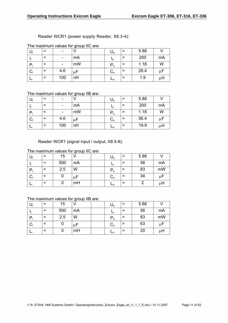
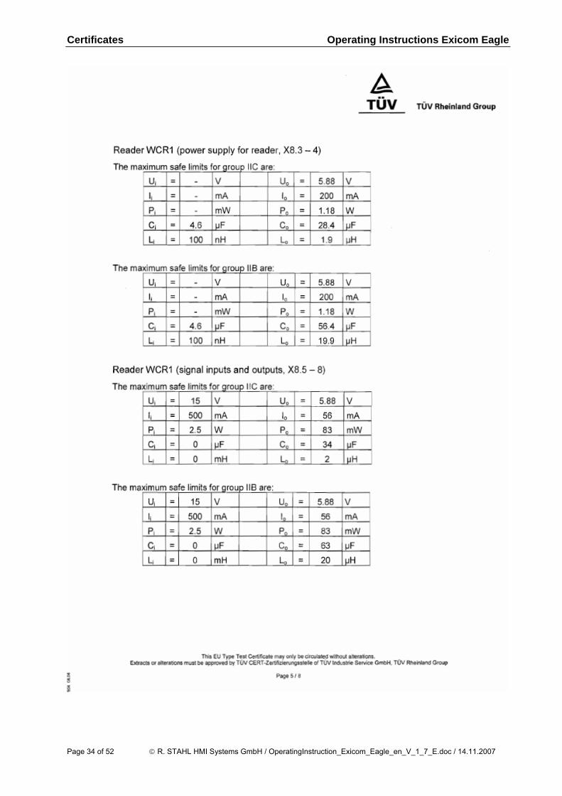
Reader WCR1 (power supply Reader, X8.3-4):
The maximum values for group IIC are: Ui = - V Uo = 5.88 V
Ii = - mA lo = 200 mA
Pi = - mW Po = 1.18 W
Ci = 4.6 μF Co = 28.4 μF
Li = 100 nH Lo = 1.9 μH
The maximum values for group IIB are: Ui = - V Uo = 5.88 V
Ii = - mA lo = 200 mA
Pi = - mW Po = 1.18 W
Ci = 4.6 μF Co = 56.4 μF
Li = 100 nH Lo = 19.9 μH
Reader WCR1 (signal input / output, X8.5-8):
The maximum values for group IIC are: Ui = 15 V Uo = 5.88 V
Ii = 500 mA lo = 56 mA
Pi = 2.5 W Po = 83 mW
Ci = 0 μF Co = 34 μF
Li = 0 mH Lo = 2 μH
The maximum values for group IIB are: Ui = 15 V Uo = 5.88 V
Ii = 500 mA lo = 56 mA
Pi = 2.5 W Po = 83 mW
Ci = 0 μF Co = 63 μF
Li = 0 mH Lo = 20 μH
© R. STAHL HMI Systems GmbH / OperatingInstruction_Exicom_Eagle_en_V_1_7_E.doc / 14.11.2007 Page 11 of 52
Exicom Eagle ET-306, ET-316, ET-336 Operating Instructions Exicom Eagle
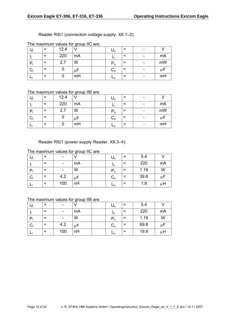
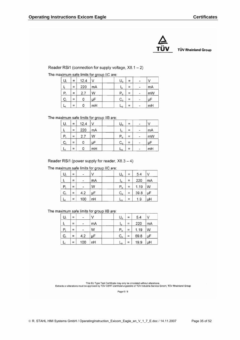
Reader RSi1 (connection voltage supply, X8.1–2):
The maximum values for group IIC are: Ui = 12.4 V Uo = - V
Ii = 220 mA lo = - mA
Pi = 2.7 W Po = - mW
Ci = 0 μF Co = - μF
Li = 0 mH Lo = - mH
The maximum values for group IIB are: Ui = 12.4 V Uo = - V
Ii = 220 mA lo = - mA
Pi = 2.7 W Po = - mW
Ci = 0 μF Co = - μF
Li = 0 mH Lo = - mH
Reader RSi1 (power supply Reader, X8.3–4):
The maximum values for group IIC are: Ui = - V Uo = 5.4 V
Ii = - mA lo = 220 mA
Pi = - W Po = 1.19 W
Ci = 4.2 μF Co = 39.8 μF
Li = 100 nH Lo = 1.9 μH
The maximum values for group IIB are: Ui = - V Uo = 5.4 V
Ii = - mA lo = 220 mA
Pi = - W Po = 1.19 W
Ci = 4.2 μF Co = 69.8 μF
Li = 100 nH Lo = 19.9 μH
Page 12 of 52 © R. STAHL HMI Systems GmbH / OperatingInstruction_Exicom_Eagle_en_V_1_7_E.doc / 14.11.2007
Operating Instructions Exicom Eagle Exicom Eagle ET-306, ET-316, ET-336
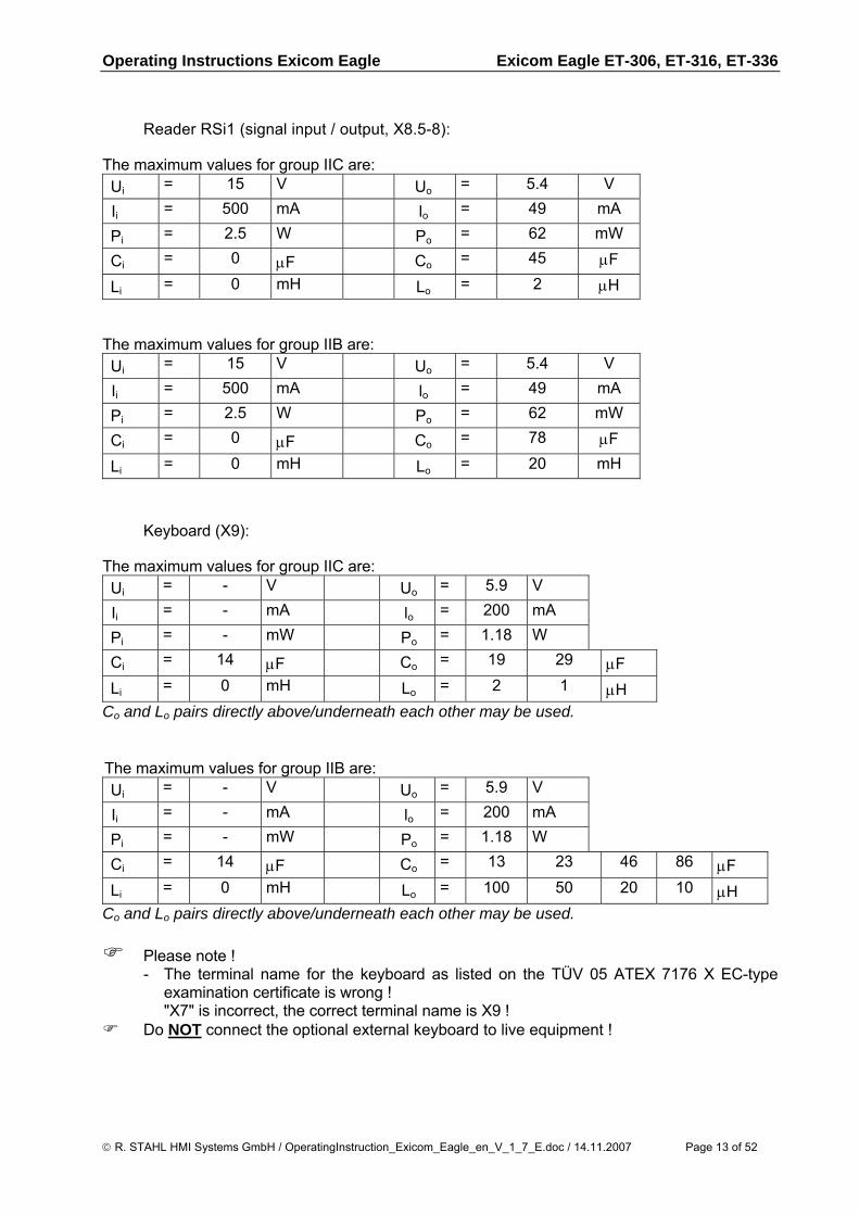
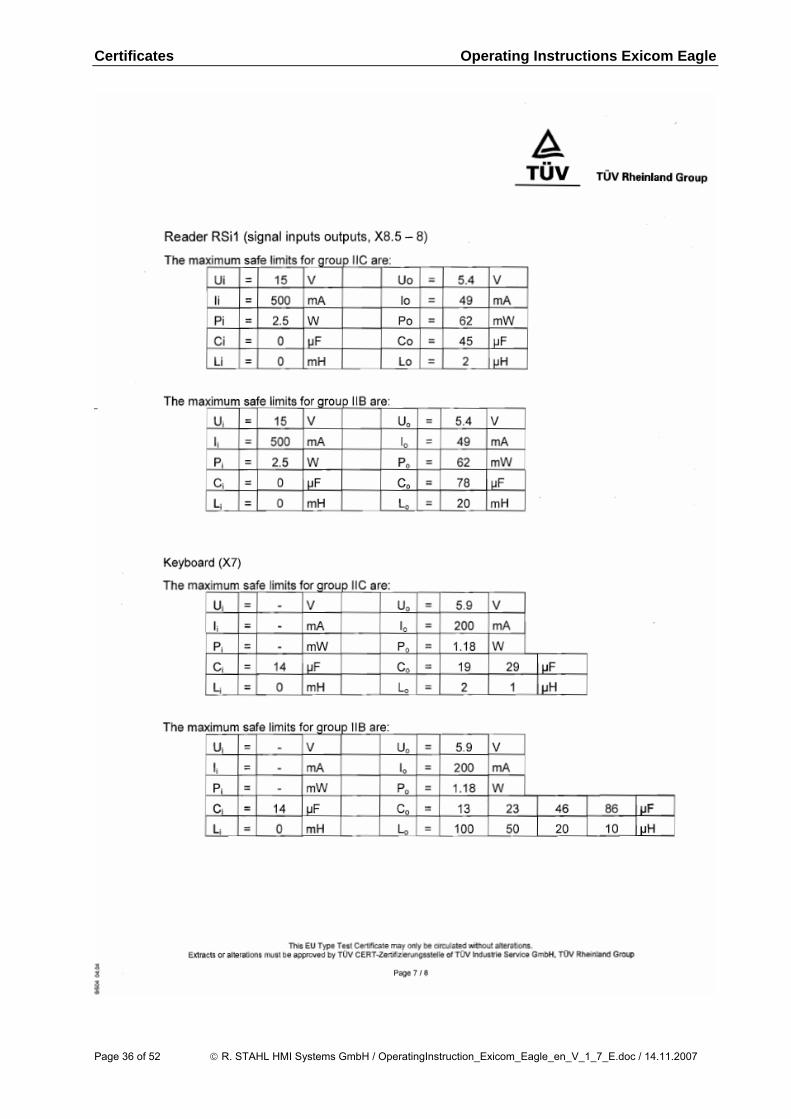
Reader RSi1 (signal input / output, X8.5-8):
The maximum values for group IIC are: Ui = 15 V Uo = 5.4 V
Ii = 500 mA lo = 49 mA
Pi = 2.5 W Po = 62 mW
Ci = 0 μF Co = 45 μF
Li = 0 mH Lo = 2 μH
The maximum values for group IIB are: Ui = 15 V Uo = 5.4 V
Ii = 500 mA lo = 49 mA
Pi = 2.5 W Po = 62 mW
Ci = 0 μF Co = 78 μF
Li = 0 mH Lo = 20 mH
Keyboard (X9):
The maximum values for group IIC are: Ui = - V Uo = 5.9 V
Ii = - mA lo = 200 mA
Pi = - mW Po = 1.18 W
Ci = 14 μF Co = 19 29 μF Li = 0 mH Lo = 2 1 μH
Co and Lo pairs directly above/underneath each other may be used.
The maximum values for group IIB are: Ui = - V Uo = 5.9 V
Ii = - mA lo = 200 mA
Pi = - mW Po = 1.18 W
Ci = 14 μF Co = 13 23 46 86 μF Li = 0 mH Lo = 100 50 20 10 μH
Co and Lo pairs directly above/underneath each other may be used.
Please note ! - The terminal name for the keyboard as listed on the TÜV 05 ATEX 7176 X EC-type
examination certificate is wrong ! "X7" is incorrect, the correct terminal name is X9 !
Do NOT connect the optional external keyboard to live equipment !
© R. STAHL HMI Systems GmbH / OperatingInstruction_Exicom_Eagle_en_V_1_7_E.doc / 14.11.2007 Page 13 of 52

Exicom Eagle ET-306, ET-316, ET-336 Operating Instructions Exicom Eagle
2.6 Type code Exicom ET-xxx-*** Plug-in module (optional) 306 / 316 / 336 Product type: Version Plug-in module Exicom ET-xxx - Exicom ET-xxx-RSi Barcode or proximity reader Exicom ET-xxx-WCR Wiegand reader
Page 14 of 52 © R. STAHL HMI Systems GmbH / OperatingInstruction_Exicom_Eagle_en_V_1_7_E.doc / 14.11.2007
Operating Instructions Exicom Eagle Exicom Eagle ET-306, ET-316, ET-336
2.7 Safety Advice This chapter is a summary of the key safety measures. The summary is supplementary to existing rules which staff also have to study. The safety of persons and equipment in hazardous areas depends on compliance with all relevant safety regulations. Thus, the installation and maintenance staff carry a particular responsibility, requiring precise knowledge of the applicable regulations and conditions. 2.7.1 Installation and operation Please note the following when installing and operating the device:
• During assembly and operation of the operator interface electrostatic surface charging must not exceed that caused by manual rubbing.
• The national regulations for installation and assembly apply (e.g. EN 60079-1).
• The operator interfaces may be installed in zones 1, 2, 21 or 22.
• The intrinsically safe circuits must be installed according to applicable regulations.
• The operator interface must only be switched on when it is closed.
• When installed in zones 1, 2, 21 and 22, intrinsically safe devices suitable for zones 1, 2, 21 and 22 may be connected to the intrinsically safe power supply circuits.
• The safe maximum values of the connected field device(s) must correspond to the values listed on the data sheet or the EC type examination certificate.
• Interconnecting several active devices in an intrinsically safe circuit may result in different safe maximum values. This could compromise intrinsic safety !
• After switching the operator interface off, wait for at least 10 minutes before opening it.
• Before opening the housing lid users must ensure that all non-intrinsically safe circuits have been switched off. Circuits supplied from different sources may be connected ! Please note that all associated equipment (such as the SK-KJ1710, for example) must also be switched off !
• National safety and accident prevention rules.
• Generally accepted technical rules.
• Safety instructions contained in these operating instructions.
• Any damage may compromise the explosion protection !
Use the operator interface for its intended purpose only (see "Function"). Incorrect or unauthorized use and non-compliance with the instructions in this manual will void any warranty on our part. No changes may be made to the operator interface or its components that compromise explosion protection ! The operator interface may only be installed and operated in an undamaged, dry and clean condition !
© R. STAHL HMI Systems GmbH / OperatingInstruction_Exicom_Eagle_en_V_1_7_E.doc / 14.11.2007 Page 15 of 52
Exicom Eagle ET-306, ET-316, ET-336 Operating Instructions Exicom Eagle
2.7.2 Special conditions
• The housing of the operator interface must be protected against prolonged UV radiation.
• The operator interface and any connected equipment must be incorporated into the same potential equalization system (see installation example in the Hardware Manual). An alternative would be to connect only devices that are safely isolated from earth potential.
2.7.3 Software installation Installation of software on the operator interfaces: 2.7.3.1 Software installation using a USB Memory Stick You may only use USB memory sticks permitted for use by R. STAHL HMI Systems GmbH. These USB memory sticks are below and in general referred to by R. STAHL HMI Systems GmbH as "USB(i) Drives". Data may only be copied onto the operator interfaces and software may only be installed with these USB Drives.
• In hazardous areas you may only use I.S. certified USB Drives supplied by R. STAHL HMI Systems GmbH.
• In an industrial area, a permitted, non-explosion proof memory stick may be connected to the I.S. USB interface of the operator interface after having been connected to any PC.
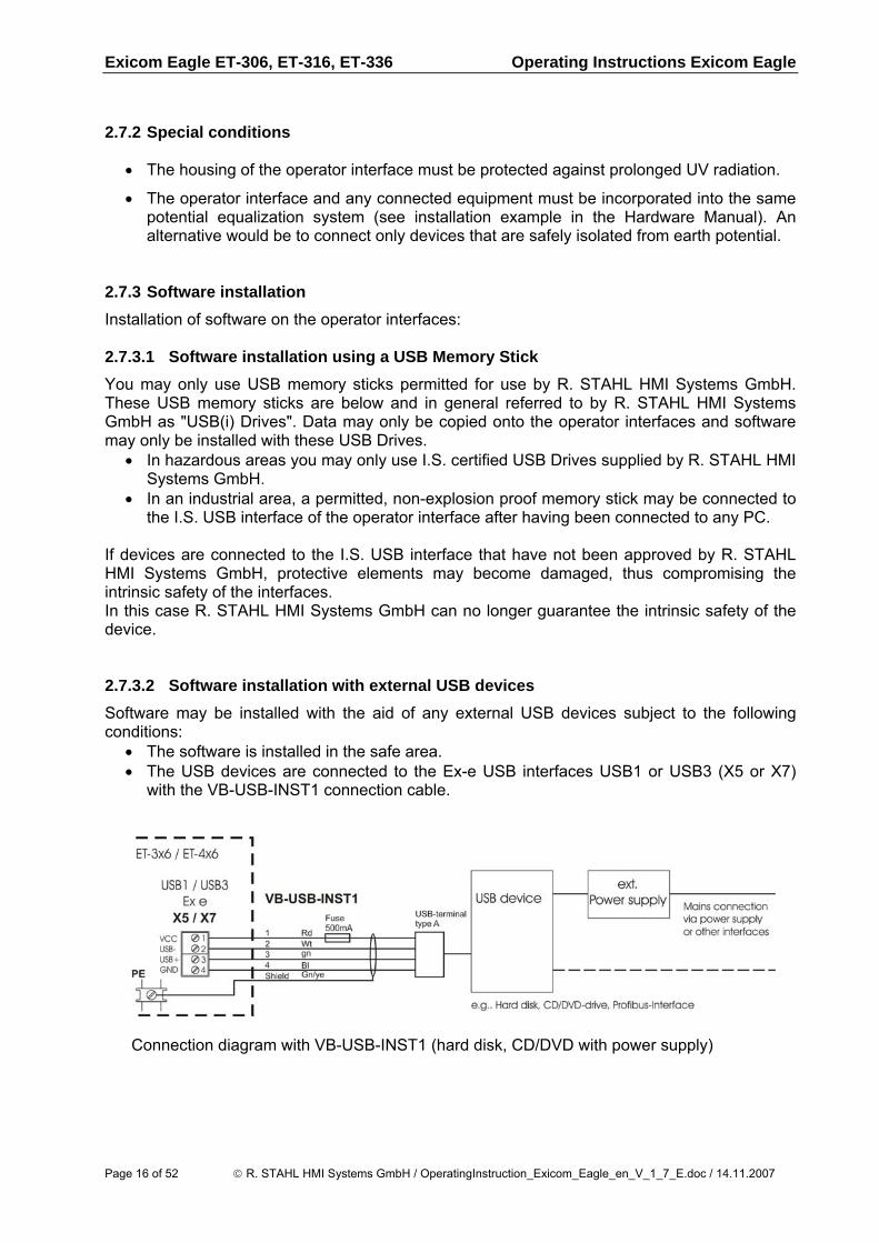
If devices are connected to the I.S. USB interface that have not been approved by R. STAHL HMI Systems GmbH, protective elements may become damaged, thus compromising the intrinsic safety of the interfaces. In this case R. STAHL HMI Systems GmbH can no longer guarantee the intrinsic safety of the device. 2.7.3.2 Software installation with external USB devices Software may be installed with the aid of any external USB devices subject to the following conditions:
• The software is installed in the safe area. • The USB devices are connected to the Ex-e USB interfaces USB1 or USB3 (X5 or X7)
with the VB-USB-INST1 connection cable.
Connection diagram with VB-USB-INST1 (hard disk, CD/DVD with power supply)
Page 16 of 52 © R. STAHL HMI Systems GmbH / OperatingInstruction_Exicom_Eagle_en_V_1_7_E.doc / 14.11.2007
Operating Instructions Exicom Eagle Exicom Eagle ET-306, ET-316, ET-336
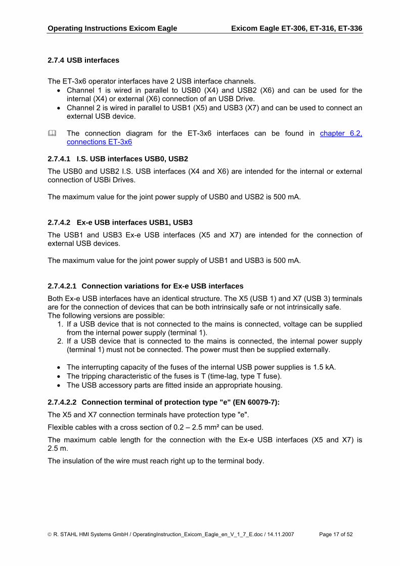
2.7.4 USB interfaces The ET-3x6 operator interfaces have 2 USB interface channels.
• Channel 1 is wired in parallel to USB0 (X4) and USB2 (X6) and can be used for the internal (X4) or external (X6) connection of an USB Drive.
• Channel 2 is wired in parallel to USB1 (X5) and USB3 (X7) and can be used to connect an external USB device.
The connection diagram for the ET-3x6 interfaces can be found in chapter 6.2,
connections ET-3x6 2.7.4.1 I.S. USB interfaces USB0, USB2 The USB0 and USB2 I.S. USB interfaces (X4 and X6) are intended for the internal or external connection of USBi Drives. The maximum value for the joint power supply of USB0 and USB2 is 500 mA. 2.7.4.2 Ex-e USB interfaces USB1, USB3 The USB1 and USB3 Ex-e USB interfaces (X5 and X7) are intended for the connection of external USB devices. The maximum value for the joint power supply of USB1 and USB3 is 500 mA. 2.7.4.2.1 Connection variations for Ex-e USB interfaces Both Ex-e USB interfaces have an identical structure. The X5 (USB 1) and X7 (USB 3) terminals are for the connection of devices that can be both intrinsically safe or not intrinsically safe. The following versions are possible:
1. If a USB device that is not connected to the mains is connected, voltage can be supplied from the internal power supply (terminal 1).
2. If a USB device that is connected to the mains is connected, the internal power supply (terminal 1) must not be connected. The power must then be supplied externally.
• The interrupting capacity of the fuses of the internal USB power supplies is 1.5 kA. • The tripping characteristic of the fuses is T (time-lag, type T fuse). • The USB accessory parts are fitted inside an appropriate housing.
2.7.4.2.2 Connection terminal of protection type "e" (EN 60079-7): The X5 and X7 connection terminals have protection type "e".
Flexible cables with a cross section of 0.2 – 2.5 mm² can be used.
The maximum cable length for the connection with the Ex-e USB interfaces (X5 and X7) is 2.5 m.
The insulation of the wire must reach right up to the terminal body.
© R. STAHL HMI Systems GmbH / OperatingInstruction_Exicom_Eagle_en_V_1_7_E.doc / 14.11.2007 Page 17 of 52
Exicom Eagle ET-306, ET-316, ET-336 Operating Instructions Exicom Eagle
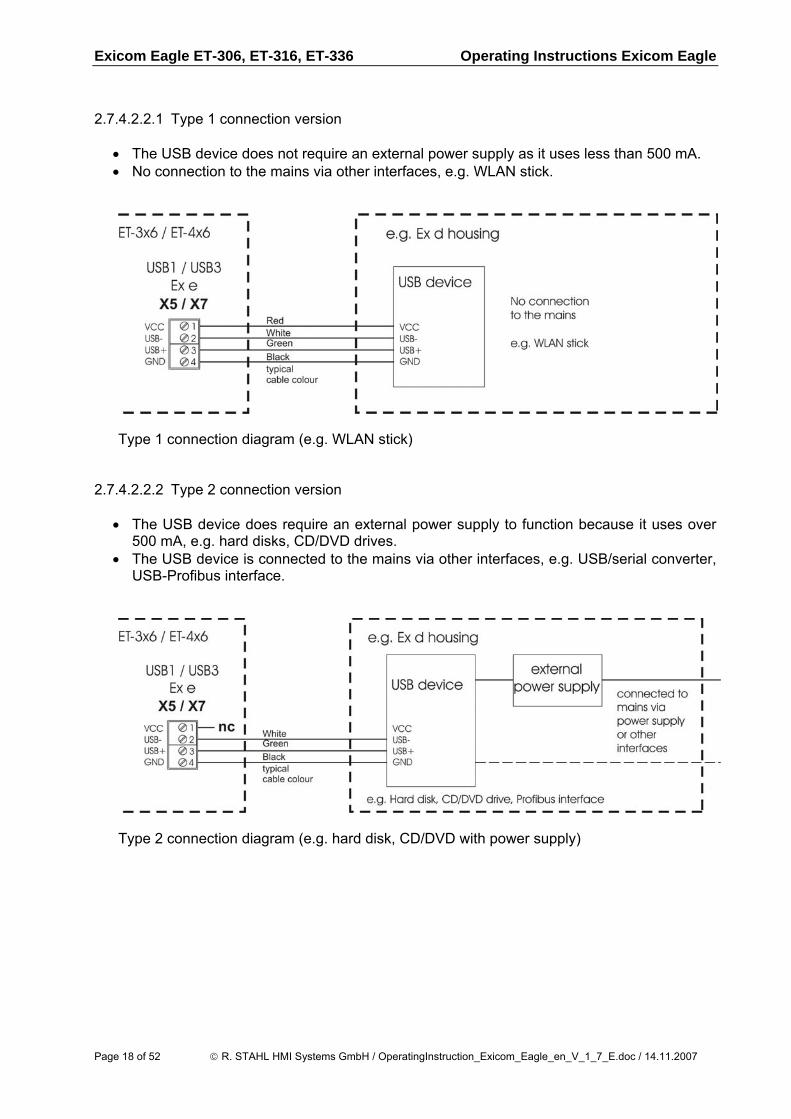
2.7.4.2.2.1 Type 1 connection version
• The USB device does not require an external power supply as it uses less than 500 mA. • No connection to the mains via other interfaces, e.g. WLAN stick.
Type 1 connection diagram (e.g. WLAN stick) 2.7.4.2.2.2 Type 2 connection version
• The USB device does require an external power supply to function because it uses over 500 mA, e.g. hard disks, CD/DVD drives.
• The USB device is connected to the mains via other interfaces, e.g. USB/serial converter, USB-Profibus interface.
Type 2 connection diagram (e.g. hard disk, CD/DVD with power supply)
Page 18 of 52 © R. STAHL HMI Systems GmbH / OperatingInstruction_Exicom_Eagle_en_V_1_7_E.doc / 14.11.2007
Operating Instructions Exicom Eagle Installation
3 Installation 3.1 General information Electrical installations are subject to the relevant regulations for installation and operation, such as RL 1999/92/EC, RL 94/9EC, ElexV, IEC/EN 60079-14 and VDE 0100. The operators of electrical installations in hazardous environments must ensure that the equipment is kept in proper condition, is operated according to instructions and that maintenance and repairs are carried out. (ElexV and EN 60079-14). 3.2 ET-306, ET-316, ET-336
• The operator interfaces may be installed in zones 1, 2, 21 or 22. The intrinsically safe circuits must be installed according to applicable regulations.
• Intrinsically safe and non intrinsically safe conducting connection parts must be installed with a minimum distance of 50 mm.
• The operator interfaces are constructed according to protection type IP65 and must therefore be protected from adverse environmental conditions such as splashed water or dirt exceeding pollution degree 2.
• If the operator interfaces are installed inside a STAHL field housing, the front has IP66. The complete system is therefore tested and certified according to IP66.
• Operators must ensure compliance with the EC type examination certificates before installation. Users must adhere to any “special conditions” therein. Also of importance are the maximum electrical operating values specified therein.
• When connecting the operator interfaces to the intrinsically safe circuits of the associated equipment the respective maximum values of the field unit and the associated equipment must be observed to ensure explosion protection (proof of intrinsic safety).
• The earth/ground (PA) connector at the back of the operator interface housing must be connected to the equipotential bonding conductor of the hazardous area. To prevent equalizing currents flowing to the earth/ground (PA) system of the operator interface it is necessary to safely isolate any connected devices from earth or to integrate them into the earth/ground (PA) system of the operator interface.
• The PA connection part of the operator interface, located at the back of the housing, is internally connected to the GND supply cable (X1, pins 3 and 4).
• Ex-e terminal blocks may be mounted inside the connection box of the housing. They can, for example, serve as a sub-distribution unit for supply and signal lines of accessories mounted in separate housings and connected to the Exicom device's interfaces. These terminal blocks are installed during production of the operator interface. Customers must not attempt to mount the blocks into the devices themselves.
© R. STAHL HMI Systems GmbH / OperatingInstruction_Exicom_Eagle_en_V_1_7_E.doc / 14.11.2007 Page 19 of 52
Application Operating Instructions Exicom Eagle
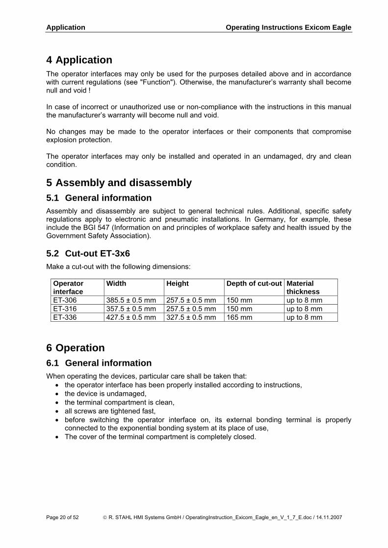
4 Application The operator interfaces may only be used for the purposes detailed above and in accordance with current regulations (see "Function"). Otherwise, the manufacturer’s warranty shall become null and void ! In case of incorrect or unauthorized use or non-compliance with the instructions in this manual the manufacturer’s warranty will become null and void. No changes may be made to the operator interfaces or their components that compromise explosion protection. The operator interfaces may only be installed and operated in an undamaged, dry and clean condition. 5 Assembly and disassembly 5.1 General information Assembly and disassembly are subject to general technical rules. Additional, specific safety regulations apply to electronic and pneumatic installations. In Germany, for example, these include the BGI 547 (Information on and principles of workplace safety and health issued by the Government Safety Association). 5.2 Cut-out ET-3x6 Make a cut-out with the following dimensions:
Operator interface
Width Height Depth of cut-out Material thickness
ET-306 385.5 ± 0.5 mm 257.5 ± 0.5 mm 150 mm up to 8 mm ET-316 357.5 ± 0.5 mm 257.5 ± 0.5 mm 150 mm up to 8 mm ET-336 427.5 ± 0.5 mm 327.5 ± 0.5 mm 165 mm up to 8 mm
6 Operation 6.1 General information When operating the devices, particular care shall be taken that:
• the operator interface has been properly installed according to instructions, • the device is undamaged, • the terminal compartment is clean, • all screws are tightened fast, • before switching the operator interface on, its external bonding terminal is properly
connected to the exponential bonding system at its place of use, • The cover of the terminal compartment is completely closed.
Page 20 of 52 © R. STAHL HMI Systems GmbH / OperatingInstruction_Exicom_Eagle_en_V_1_7_E.doc / 14.11.2007
Operating Instructions Exicom Eagle Operation
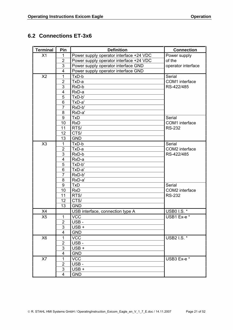
6.2 Connections ET-3x6
Terminal Pin Definition Connection X1 1 Power supply operator interface +24 VDC Power supply
2 Power supply operator interface +24 VDC of the 3 Power supply operator interface GND operator interface 4 Power supply operator interface GND
X2 1 TxD-b Serial 2 TxD-a COM1 interface 3 RxD-b RS-422/485 4 RxD-a 5 TxD-b' 6 TxD-a' 7 RxD-b' 8 RxD-a' 9 TxD Serial 10 RxD COM1 interface 11 RTS/ RS-232 12 CTS/ 13 GND
X3 1 TxD-b Serial 2 TxD-a COM2 interface 3 RxD-b RS-422/485 4 RxD-a 5 TxD-b' 6 TxD-a' 7 RxD-b' 8 RxD-a' 9 TxD Serial 10 RxD COM2 interface 11 RTS/ RS-232 12 CTS/ 13 GND
X4 USB interface, connection type A USB0 I.S. * X5 1 VCC USB1 Ex-e *
2 USB - 3 USB + 4 GND
X6 1 VCC USB2 I.S. * 2 USB - 3 USB + 4 GND
X7 1 VCC USB3 Ex-e * 2 USB - 3 USB + 4 GND
© R. STAHL HMI Systems GmbH / OperatingInstruction_Exicom_Eagle_en_V_1_7_E.doc / 14.11.2007 Page 21 of 52
Operation Operating Instructions Exicom Eagle
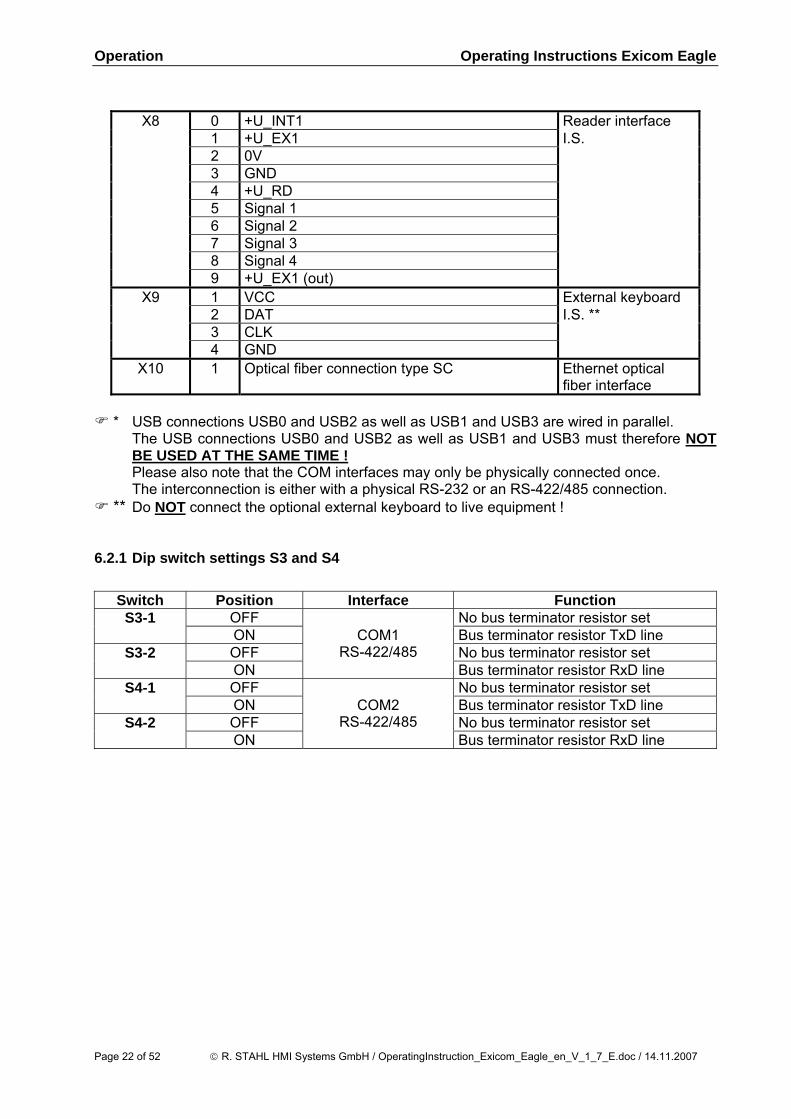
X8 0 +U_INT1 Reader interface
1 +U_EX1 I.S. 2 0V 3 GND 4 +U_RD 5 Signal 1 6 Signal 2 7 Signal 3 8 Signal 4 9 +U_EX1 (out)
X9 1 VCC External keyboard 2 DAT I.S. ** 3 CLK 4 GND
X10 1 Optical fiber connection type SC Ethernet optical fiber interface
* USB connections USB0 and USB2 as well as USB1 and USB3 are wired in parallel.
The USB connections USB0 and USB2 as well as USB1 and USB3 must therefore NOT BE USED AT THE SAME TIME !
Please also note that the COM interfaces may only be physically connected once. The interconnection is either with a physical RS-232 or an RS-422/485 connection.
** Do NOT connect the optional external keyboard to live equipment ! 6.2.1 Dip switch settings S3 and S4
Switch Position Interface Function S3-1 OFF No bus terminator resistor set
ON Bus terminator resistor TxD line S3-2 OFF No bus terminator resistor set
ON
COM1 RS-422/485
Bus terminator resistor RxD line S4-1 OFF No bus terminator resistor set
ON Bus terminator resistor TxD line S4-2 OFF No bus terminator resistor set
ON
COM2 RS-422/485
Bus terminator resistor RxD line
Page 22 of 52 © R. STAHL HMI Systems GmbH / OperatingInstruction_Exicom_Eagle_en_V_1_7_E.doc / 14.11.2007
Operating Instructions Exicom Eagle Operation
6.3 Connections Ex-e terminals (X12) Ex-e terminal blocks may be mounted inside the connection box of the housing. Because these terminal blocks are exclusively mounted during production, this option must be specified when ordering the product. For devices with these optional terminal blocks, please note the following:
• Only Ex-e circuits may be connected to these terminal blocks ! • An interconnection of Ex-e and other circuits is not permitted ! When connecting cables please ensure that the cable isolation goes right up to the
terminal part. 6.3.1 Connection details of the Ex-e terminals
• Maximum nominal voltage: 275 V • Maximum nominal voltage: (if the fixed bridge bar is used): 175 V • Rated current: 4 A • Maximum rated current: 5 A
6.3.2 Cable types and cross sections Copper cables with the following cross sections may be used:
• Maximum cable cross section in mm² (AWG) 4 (12) • Minimum cable cross section in mm² (AWG) 0.2 (24)
Multiple cable connection to the screw terminal (2 cables of the same cross section and cable type):
• flexible mm² (AWG) 0.2 – 1.5 (24 – 16) • rigid mm² (AWG) 0.2 – 1.5 (24 – 16)
Which cable cross sections are chosen should be decided on the basis of relevant regulations, such as DIN VDE 0298. Factors that might require a larger cross section, such as current, increased temperatures, cable bundling, etc. must also be taken into account.
© R. STAHL HMI Systems GmbH / OperatingInstruction_Exicom_Eagle_en_V_1_7_E.doc / 14.11.2007 Page 23 of 52
Maintenance, service Operating Instructions Exicom Eagle
7 Maintenance, service Associated equipment is subject to maintenance, service and testing according to guidelines 1999/92/EC, IEC 60079-19 and EN 60079-17 ! Because the transmission of the devices remains reliable and stable over long periods of time, regular adjustments are not required.
• Only original parts provided by the manufacturer must be used. • Fuses may only be replaced by equivalent fuse types.
System maintenance should focus on the following:
a. Seal wear b. Display damage c. All screws are tightened fast d. All cables and lines are properly connected and undamaged
7.1.1 Servicing In accordance with IEC 60079-19 and EN 60079-17, operators of electric plants in hazardous areas are obliged to have them serviced by qualified electricians. 8 Troubleshooting Devices operated in hazardous areas must not be modified. Repairs may only be carried out by qualified, authorized staff specially trained for this purpose.
Repairs may only be carried out by specially trained staff who are familiar with all basic conditions of the applicable user regulations and – if necessary – have been authorized by the manufacturer.
Page 24 of 52 © R. STAHL HMI Systems GmbH / OperatingInstruction_Exicom_Eagle_en_V_1_7_E.doc / 14.11.2007
Operating Instructions Exicom Eagle Disposal
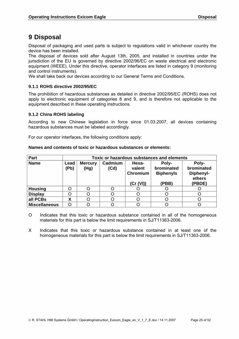
9 Disposal Disposal of packaging and used parts is subject to regulations valid in whichever country the device has been installed. The disposal of devices sold after August 13th, 2005, and installed in countries under the jurisdiction of the EU is governed by directive 2002/96/EC on waste electrical and electronic equipment (WEEE). Under this directive, operator interfaces are listed in category 9 (monitoring and control instruments). We shall take back our devices according to our General Terms and Conditions. 9.1.1 ROHS directive 2002/95/EC The prohibition of hazardous substances as detailed in directive 2002/95/EC (ROHS) does not apply to electronic equipment of categories 8 and 9, and is therefore not applicable to the equipment described in these operating instructions. 9.1.2 China ROHS labeling According to new Chinese legislation in force since 01.03.2007, all devices containing hazardous substances must be labeled accordingly. For our operator interfaces, the following conditions apply: Names and contents of toxic or hazardous substances or elements: Part Toxic or hazardous substances and elements Name Lead
(Pb) Mercury
(Hg) Cadmium
(Cd) Hexa-valent
Chromium
(Cr (VI))
Poly-brominated Biphenyls
(PBB)
Poly-brominated Diphenyl-
ethers (PBDE)
Housing O O O O O O Display O O O O O O all PCBs X O O O O O Miscellaneous O O O O O O O Indicates that this toxic or hazardous substance contained in all of the homogeneous
materials for this part is below the limit requirements in SJ/T11363-2006. X Indicates that this toxic or hazardous substance contained in at least one of the
homogeneous materials for this part is below the limit requirements in SJ/T11363-2006.
© R. STAHL HMI Systems GmbH / OperatingInstruction_Exicom_Eagle_en_V_1_7_E.doc / 14.11.2007 Page 25 of 52
Accessories Operating Instructions Exicom Eagle
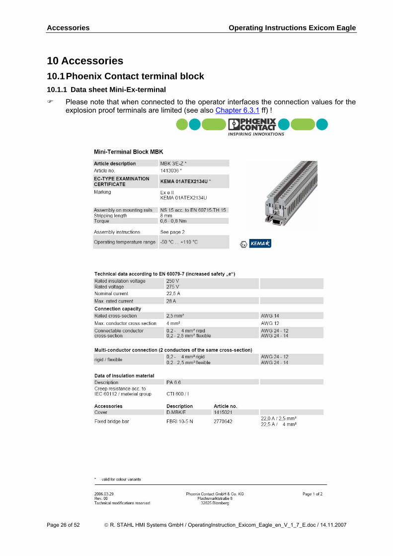
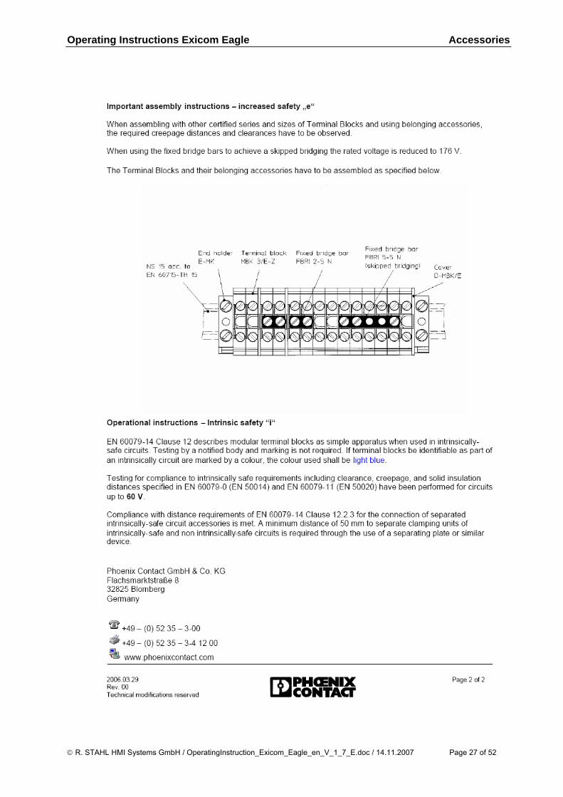
10 Accessories 10.1 Phoenix Contact terminal block 10.1.1 Data sheet Mini-Ex-terminal
Please note that when connected to the operator interfaces the connection values for the explosion proof terminals are limited (see also Chapter 6.3.1 ff) !
Page 26 of 52 © R. STAHL HMI Systems GmbH / OperatingInstruction_Exicom_Eagle_en_V_1_7_E.doc / 14.11.2007
Operating Instructions Exicom Eagle Accessories
© R. STAHL HMI Systems GmbH / OperatingInstruction_Exicom_Eagle_en_V_1_7_E.doc / 14.11.2007 Page 27 of 52
Certificates Operating Instructions Exicom Eagle
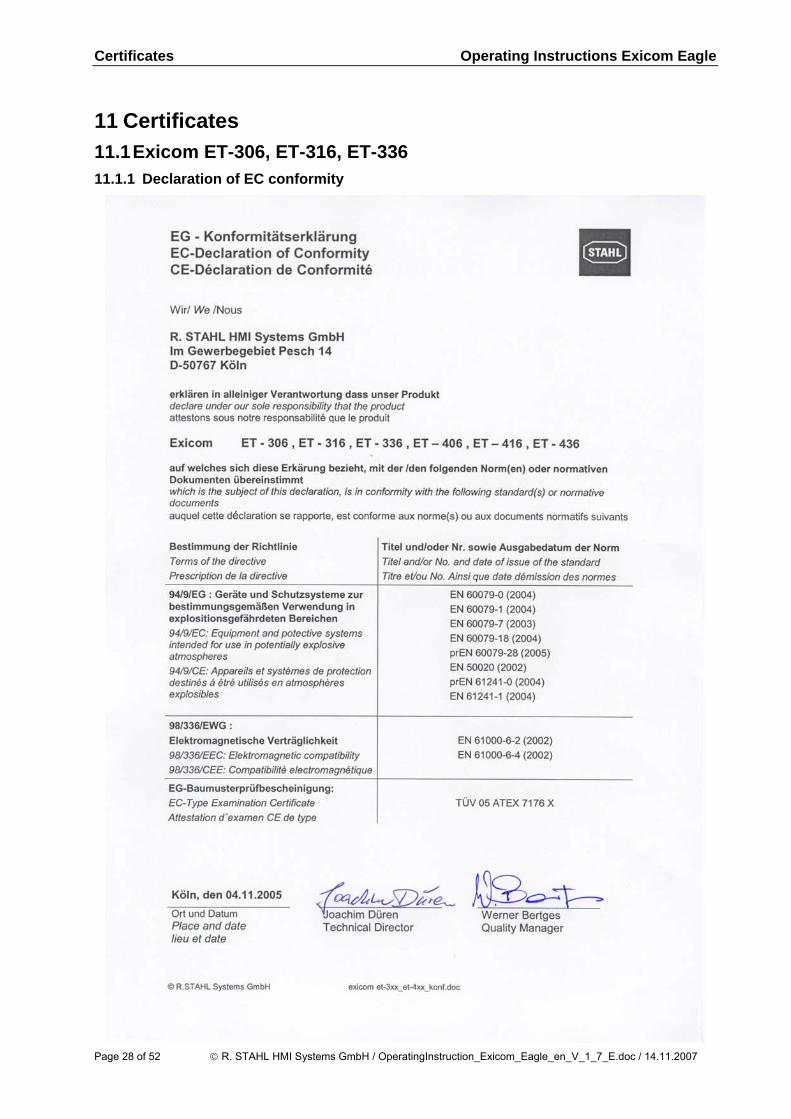
11 Certificates 11.1 Exicom ET-306, ET-316, ET-336 11.1.1 Declaration of EC conformity
Page 28 of 52 © R. STAHL HMI Systems GmbH / OperatingInstruction_Exicom_Eagle_en_V_1_7_E.doc / 14.11.2007
Operating Instructions Exicom Eagle Certificates
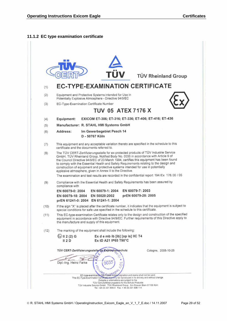
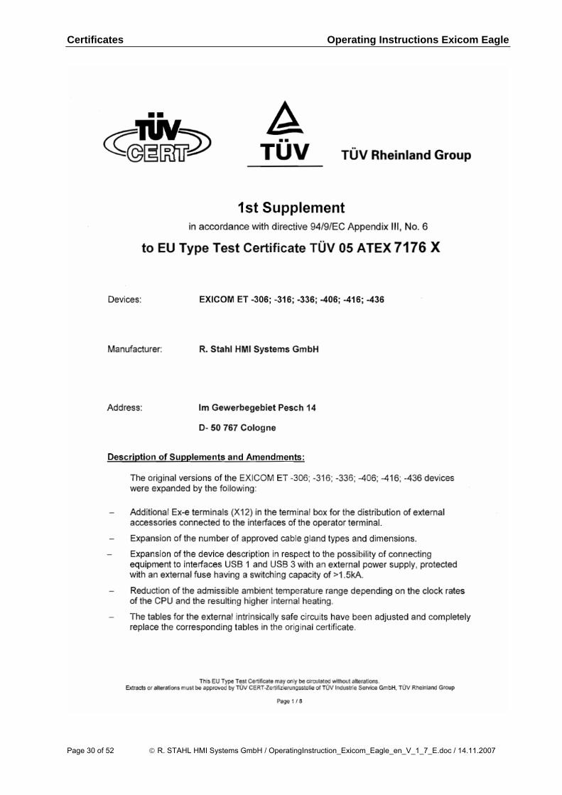
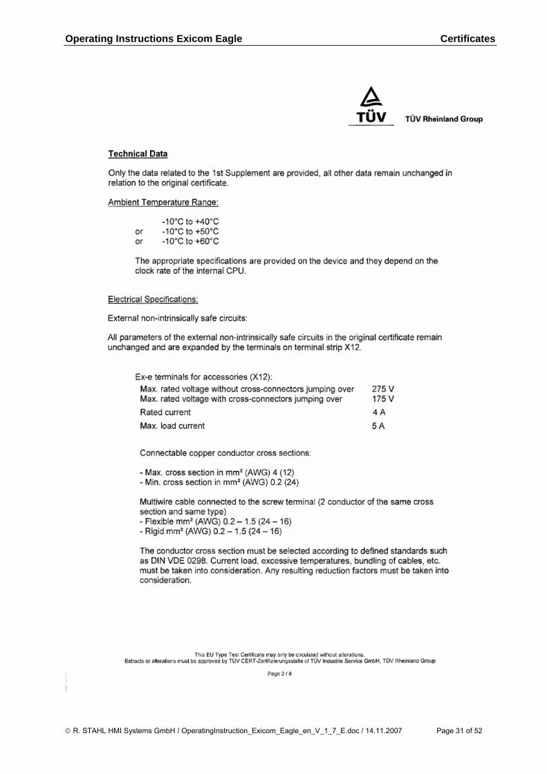
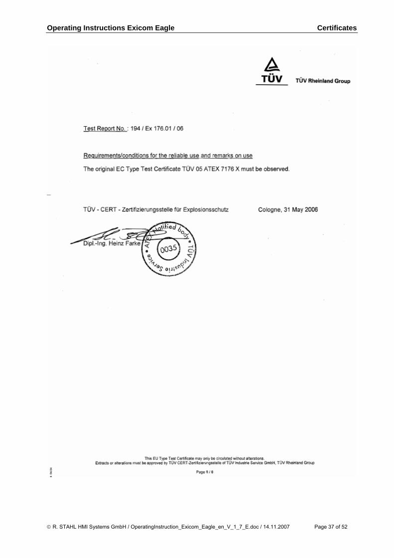
11.1.2 EC type examination certificate
© R. STAHL HMI Systems GmbH / OperatingInstruction_Exicom_Eagle_en_V_1_7_E.doc / 14.11.2007 Page 29 of 52
Certificates Operating Instructions Exicom Eagle
Page 30 of 52 © R. STAHL HMI Systems GmbH / OperatingInstruction_Exicom_Eagle_en_V_1_7_E.doc / 14.11.2007
Operating Instructions Exicom Eagle Certificates
© R. STAHL HMI Systems GmbH / OperatingInstruction_Exicom_Eagle_en_V_1_7_E.doc / 14.11.2007 Page 31 of 52
Certificates Operating Instructions Exicom Eagle
Page 32 of 52 © R. STAHL HMI Systems GmbH / OperatingInstruction_Exicom_Eagle_en_V_1_7_E.doc / 14.11.2007
Operating Instructions Exicom Eagle Certificates
© R. STAHL HMI Systems GmbH / OperatingInstruction_Exicom_Eagle_en_V_1_7_E.doc / 14.11.2007 Page 33 of 52
Certificates Operating Instructions Exicom Eagle
Page 34 of 52 © R. STAHL HMI Systems GmbH / OperatingInstruction_Exicom_Eagle_en_V_1_7_E.doc / 14.11.2007
Operating Instructions Exicom Eagle Certificates
© R. STAHL HMI Systems GmbH / OperatingInstruction_Exicom_Eagle_en_V_1_7_E.doc / 14.11.2007 Page 35 of 52
Certificates Operating Instructions Exicom Eagle
Page 36 of 52 © R. STAHL HMI Systems GmbH / OperatingInstruction_Exicom_Eagle_en_V_1_7_E.doc / 14.11.2007
Operating Instructions Exicom Eagle Certificates
© R. STAHL HMI Systems GmbH / OperatingInstruction_Exicom_Eagle_en_V_1_7_E.doc / 14.11.2007 Page 37 of 52
Certificates Operating Instructions Exicom Eagle
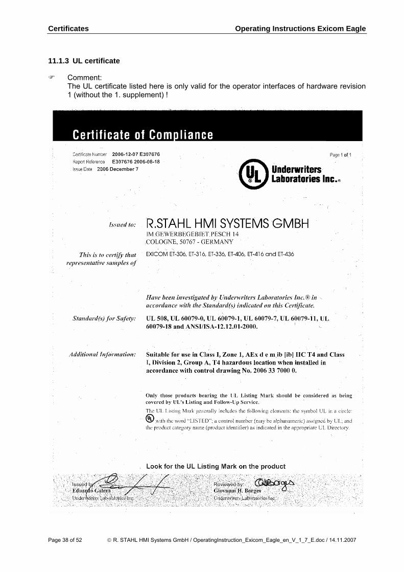
11.1.3 UL certificate
Comment: The UL certificate listed here is only valid for the operator interfaces of hardware revision
1 (without the 1. supplement) !
Page 38 of 52 © R. STAHL HMI Systems GmbH / OperatingInstruction_Exicom_Eagle_en_V_1_7_E.doc / 14.11.2007
Operating Instructions Exicom Eagle Certificates
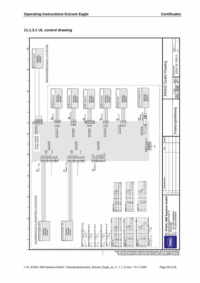
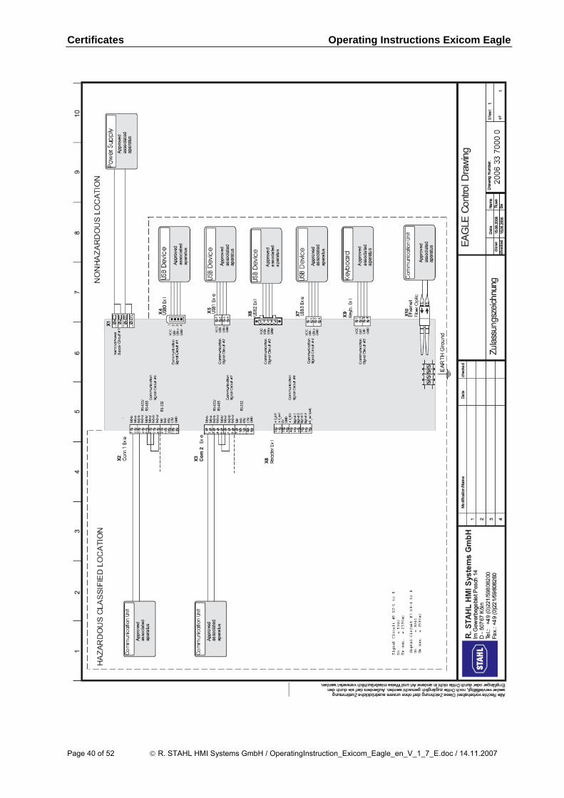
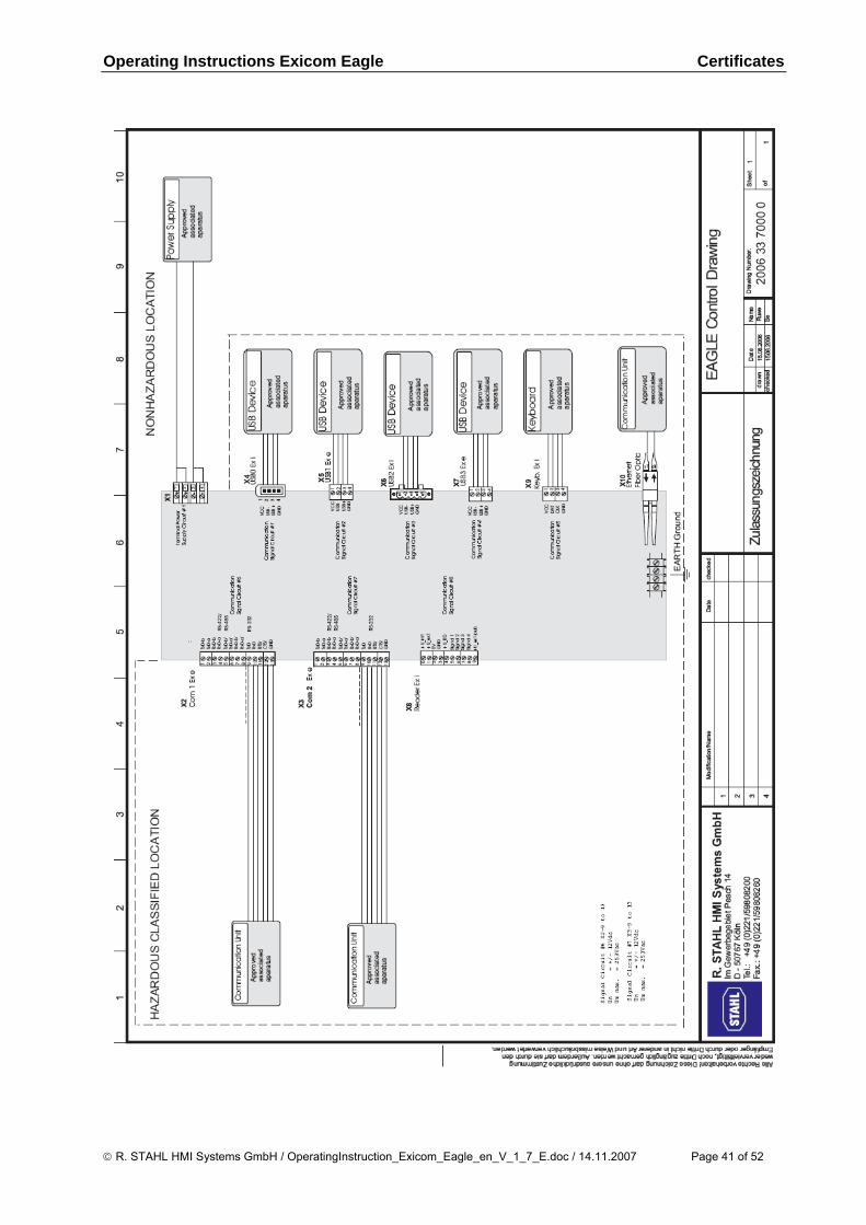
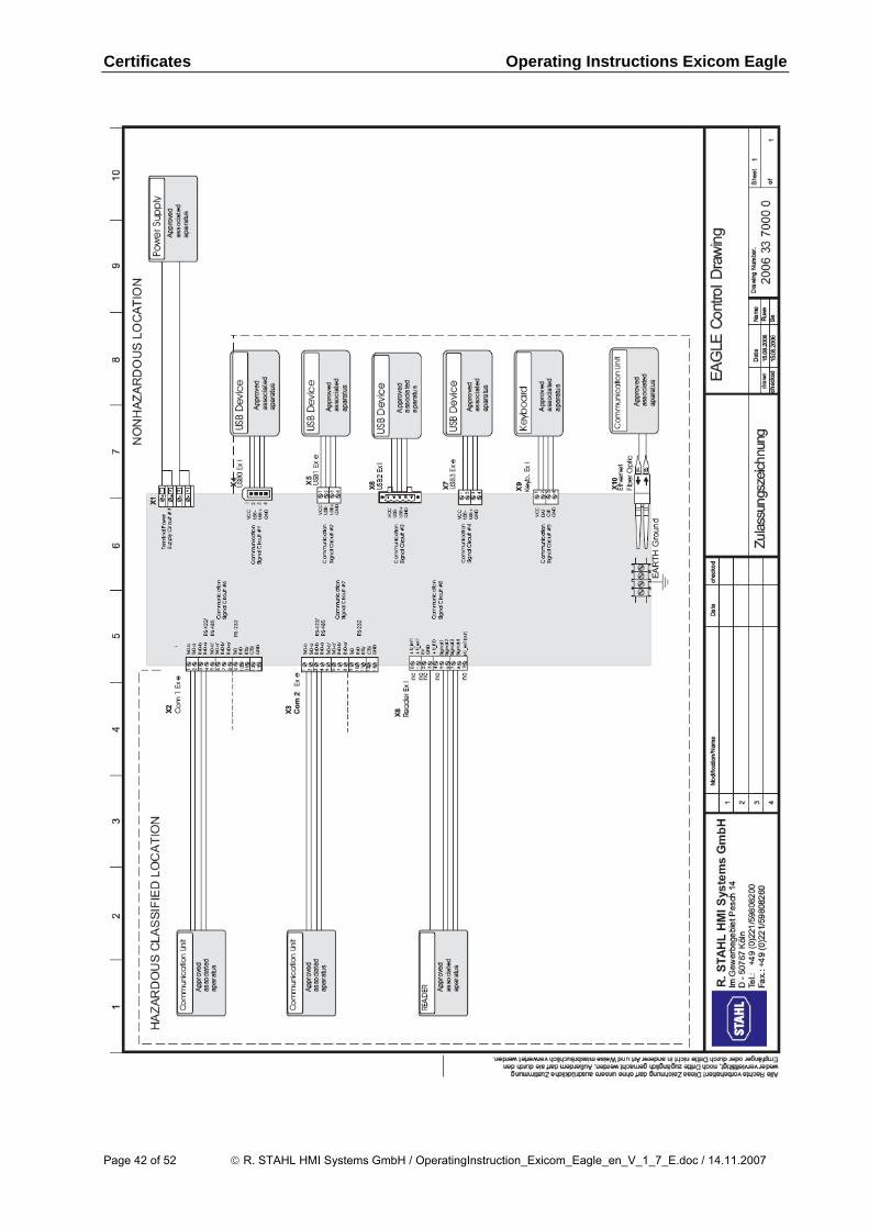
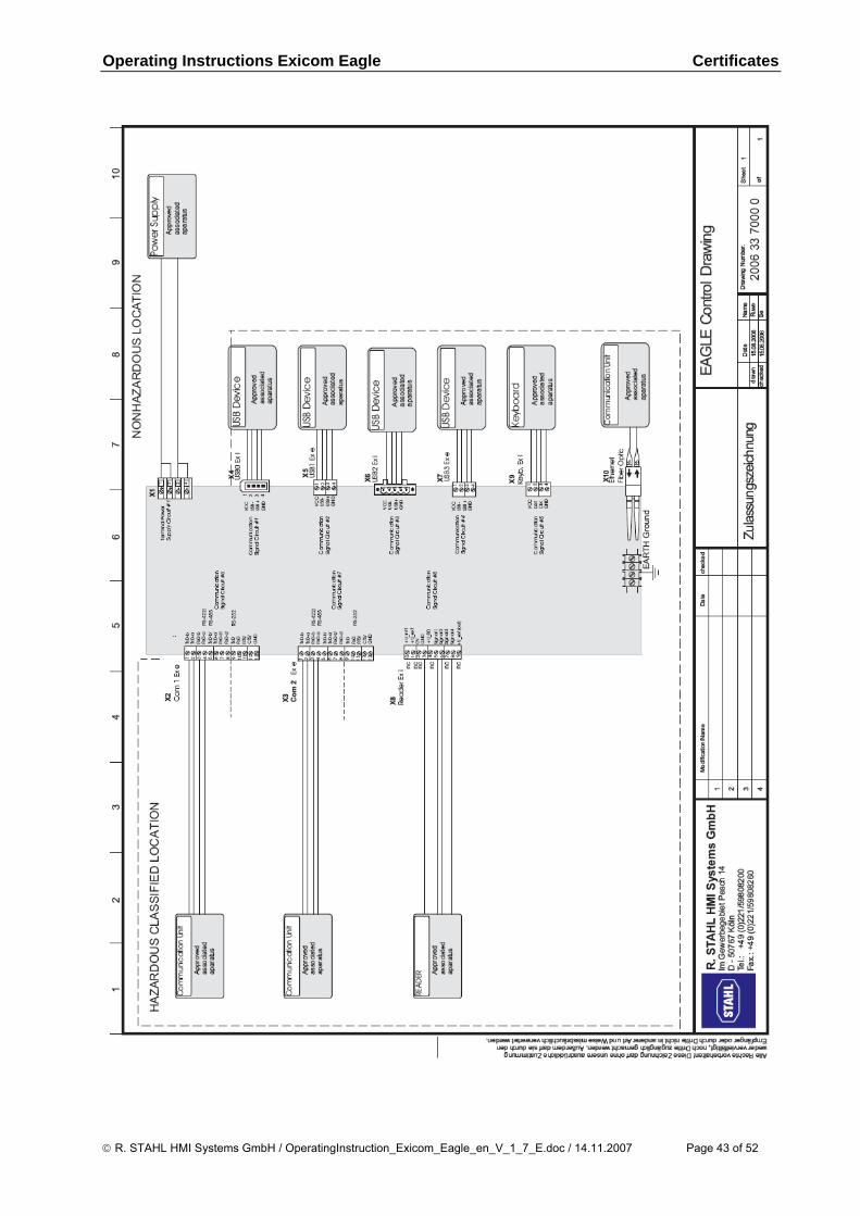
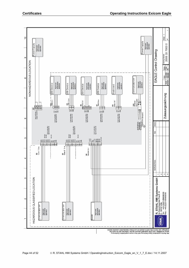
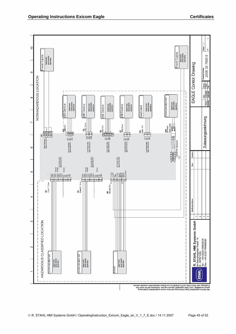
11.1.3.1 UL control drawing
© R. STAHL HMI Systems GmbH / OperatingInstruction_Exicom_Eagle_en_V_1_7_E.doc / 14.11.2007 Page 39 of 52
Certificates Operating Instructions Exicom Eagle
Page 40 of 52 © R. STAHL HMI Systems GmbH / OperatingInstruction_Exicom_Eagle_en_V_1_7_E.doc / 14.11.2007
Operating Instructions Exicom Eagle Certificates
© R. STAHL HMI Systems GmbH / OperatingInstruction_Exicom_Eagle_en_V_1_7_E.doc / 14.11.2007 Page 41 of 52
Certificates Operating Instructions Exicom Eagle
Page 42 of 52 © R. STAHL HMI Systems GmbH / OperatingInstruction_Exicom_Eagle_en_V_1_7_E.doc / 14.11.2007
Operating Instructions Exicom Eagle Certificates
© R. STAHL HMI Systems GmbH / OperatingInstruction_Exicom_Eagle_en_V_1_7_E.doc / 14.11.2007 Page 43 of 52
Certificates Operating Instructions Exicom Eagle
Page 44 of 52 © R. STAHL HMI Systems GmbH / OperatingInstruction_Exicom_Eagle_en_V_1_7_E.doc / 14.11.2007
Operating Instructions Exicom Eagle Certificates
© R. STAHL HMI Systems GmbH / OperatingInstruction_Exicom_Eagle_en_V_1_7_E.doc / 14.11.2007 Page 45 of 52
Certificates Operating Instructions Exicom Eagle
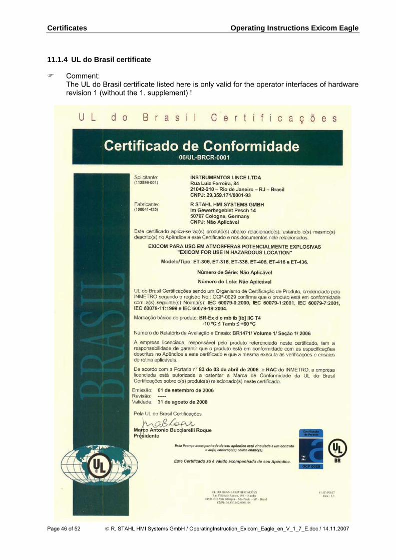
11.1.4 UL do Brasil certificate
Comment: The UL do Brasil certificate listed here is only valid for the operator interfaces of hardware
revision 1 (without the 1. supplement) !
Page 46 of 52 © R. STAHL HMI Systems GmbH / OperatingInstruction_Exicom_Eagle_en_V_1_7_E.doc / 14.11.2007

Operating Instructions Exicom Eagle Certificates
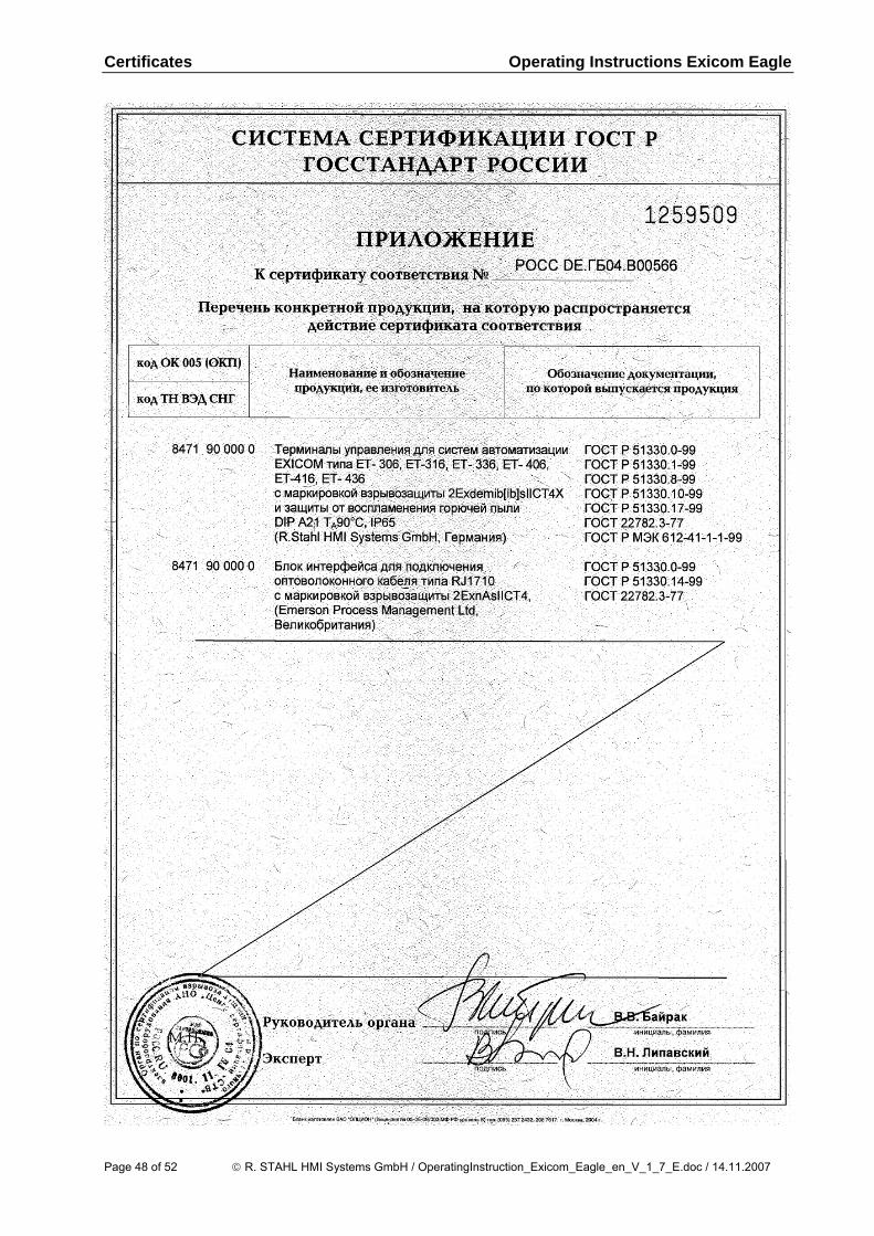
11.1.5 Gost certificate
Comment: The Gost certificate listed here is only valid for the operator interfaces of hardware
revision 1 (without the 1. supplement) ! You can find the complete certificate at chapter 9 of the hardware manual, it can be
downloaded from the homepage of R. STAHL HMI Systems GmbH or you can request it by R. STAHL HMI Systems GmbH.
© R. STAHL HMI Systems GmbH / OperatingInstruction_Exicom_Eagle_en_V_1_7_E.doc / 14.11.2007 Page 47 of 52
Certificates Operating Instructions Exicom Eagle
Page 48 of 52 © R. STAHL HMI Systems GmbH / OperatingInstruction_Exicom_Eagle_en_V_1_7_E.doc / 14.11.2007
Operating Instructions Exicom Eagle Certificates
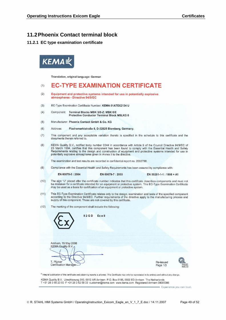
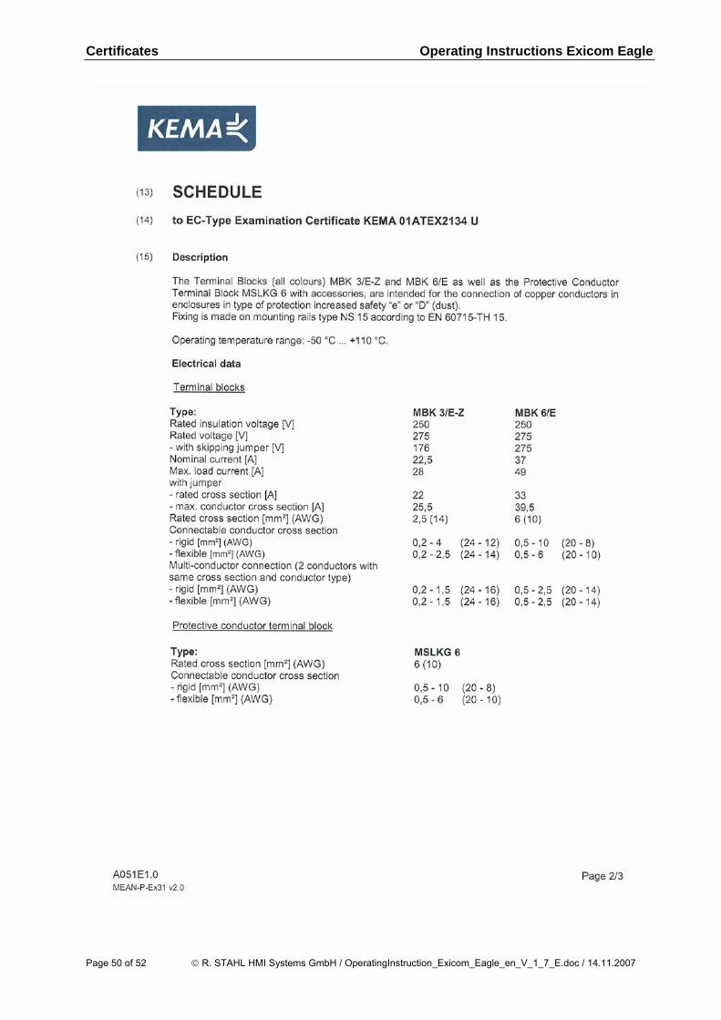
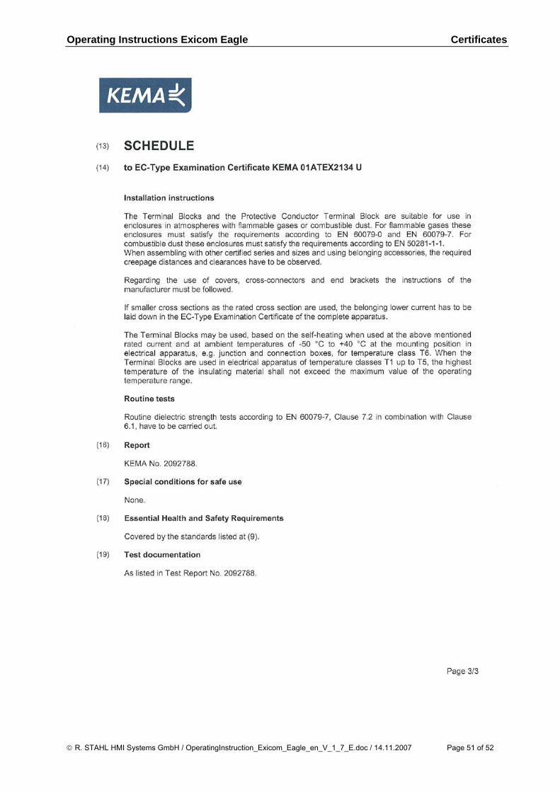
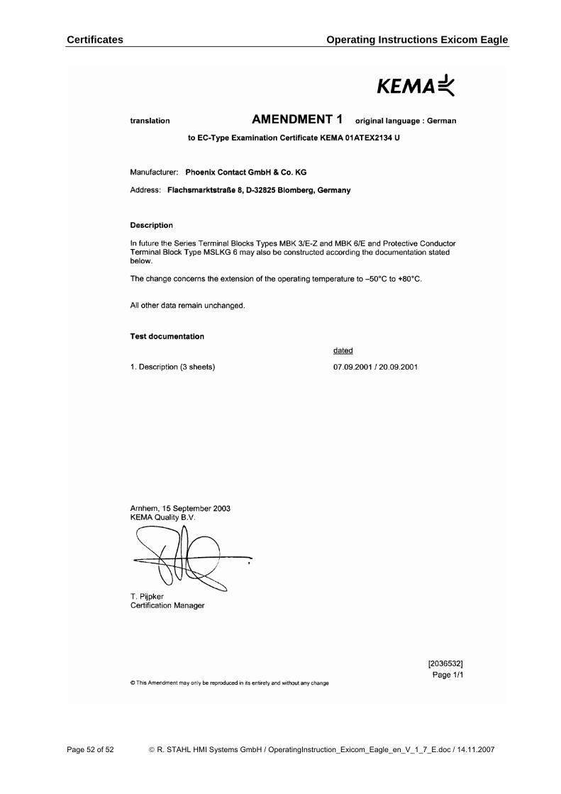
11.2 Phoenix Contact terminal block 11.2.1 EC type examination certificate
© R. STAHL HMI Systems GmbH / OperatingInstruction_Exicom_Eagle_en_V_1_7_E.doc / 14.11.2007 Page 49 of 52
Certificates Operating Instructions Exicom Eagle
Page 50 of 52 © R. STAHL HMI Systems GmbH / OperatingInstruction_Exicom_Eagle_en_V_1_7_E.doc / 14.11.2007
Operating Instructions Exicom Eagle Certificates
© R. STAHL HMI Systems GmbH / OperatingInstruction_Exicom_Eagle_en_V_1_7_E.doc / 14.11.2007 Page 51 of 52
Certificates Operating Instructions Exicom Eagle
Page 52 of 52 © R. STAHL HMI Systems GmbH / OperatingInstruction_Exicom_Eagle_en_V_1_7_E.doc / 14.11.2007