Embed Size (px)
Citation preview
www.schmalz.com
Innovative Vacuum for Automation
EN
Operating Instructions Dust Filter STF…P / STF-D…P
30.30.01.00059/02 | 11.2014

www.schmalz.com
Note
These operating instructions were written in the German language.
This document should be kept in a safe place for future reference.
The right to make technical changes is reserved. No responsibility is taken for printing errors or other
types of errors.
Publisher
© J. Schmalz GmbH, 11.2014
This document is protected by copyright. J. Schmalz GmbH retains the rights established thereby.
Reproduction of the contents, in full or in part, is only permitted within the limits of the legal provisions
of copyright law. Any modifications to or abridgments of the document are prohibited without explicit
written agreement from J. Schmalz GmbH.
Contact
J. Schmalz GmbH
Aacher Straße 29
D-72293 Glatten
Tel. +49 (0)7443 2403-0
Fax +49 (0)7443 2403-259
www.schmalz.com
Contact information for the Schmalz companies and trading partners, see
www.schmalz.com/vertriebsnetz

Contents Dust Filter STF…P / STF-D…P
www.schmalz.com
1 Basic Safety Notes .............................................................................................. 4
1.1 Classification of Safety notes ............................................................................................ 4 1.2 Warnings ........................................................................................................................... 5 1.3 Signs .................................................................................................................................. 5 1.4 General Safety Notes ........................................................................................................ 6 1.5 Intended use ...................................................................................................................... 6 1.6 Requirements for the user ................................................................................................. 7
2 Product Description ............................................................................................. 8
2.1 Versions ............................................................................................................................. 8 2.2 Dust filter with differential pressure monitoring STF-D…P ............................................... 9 2.2.1 Technical Data differential pressure monitor ..................................................................... 9 2.2.2 Principle of operation ......................................................................................................... 9
3 Installation and Operation ................................................................................. 11
3.1 General operation instructions ........................................................................................11 3.2 Installation position ..........................................................................................................11 3.3 Installation in the bracket .................................................................................................11 3.4 Mounting the hoses .........................................................................................................12
4 Maintainance ..................................................................................................... 12
4.1 Removing and cleaning filter inserts ...............................................................................12 4.2 Installing the filter cartridge .............................................................................................13 4.3 Spare and wearing parts .................................................................................................13 4.4 Put out of operation .........................................................................................................13
BASIC SAFETY NOTES
4 | EN www.schmalz.com 30.30.01.00059/02
1 Basic Safety Notes
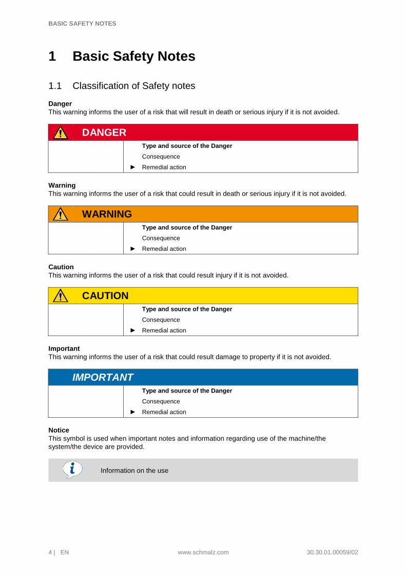
1.1 Classification of Safety notes
Danger
This warning informs the user of a risk that will result in death or serious injury if it is not avoided.
DANGER
Type and source of the Danger
Consequence
► Remedial action
Warning
This warning informs the user of a risk that could result in death or serious injury if it is not avoided.
WARNING
Type and source of the Danger
Consequence
► Remedial action
Caution
This warning informs the user of a risk that could result injury if it is not avoided.
CAUTION
Type and source of the Danger
Consequence
► Remedial action
Important
This warning informs the user of a risk that could result damage to property if it is not avoided.
IMPORTANT
Type and source of the Danger
Consequence
► Remedial action
Notice
This symbol is used when important notes and information regarding use of the machine/the
system/the device are provided.
Information on the use

BASIC SAFETY NOTES
30.30.01.00059/02 www.schmalz.com EN | 5
1.2 Warnings
Explanation of the warning symbols used in the operating instructions.
Warnings Description Warnings Description
General warning sign
Danger due to flying parts
Warning against electric shock
Warning to overpressure
Warning about dust generation
1.3 Signs
Explanation of the mandatory symbols used in the operating instructions.
Signs Description Signs Description
Wear a mask
Use protective glasses
Disconnect before servicing or repair

BASIC SAFETY NOTES
6 | EN www.schmalz.com 30.30.01.00059/02
1.4 General Safety Notes
WARNING
Ignoring the general safety guidelines
Personal injuries / damage to plants / systems
► The operating instructions contain important information on using the dust filter.
Read the operating instructions thoroughly and keep them for later reference.
► Do not connect the filter or start operations until after you have read
andunderstood the operating instructions fully.
► Use only the connections, mounting holes and attachment materials that have
been provided.
► Carry out mounting or removal only when the device is in an idle,
depressurized state.
► Only qualified specialist personnel, mechanics and electricians may perform
the installation. Qualified specialist personnel are persons who have received
technical training and have the knowledge and experience – including
knowledge of corresponding regulations – necessary to enable him or her to
recognize possible dangers and implement the appropriate safety measures
while performing tasks. The same applies to maintenance!
► General safety regulations, European standards and VDE guidelines must be
observed and complied with.
► It is not permitted to make changes to system components.
► Protect the components from damage of any kind.
1.5 Intended use
This dust filter is intended solely for filtering mechanical components in air. This device must not be used to filter other media or liquids.
The vacuum must not exceed -500 mbar. Overpressure is not permissible.
WARNING
Transport or through-suction of liquids or bulk material
Personal injury and/or damage to property
► Do not transport or suck through liquids or bulk material
CAUTION
Pressure can cause closed devices to explode
Personal injury and/or damage to property
► Wear protective glasses

BASIC SAFETY NOTES
30.30.01.00059/02 www.schmalz.com EN | 7
1.6 Requirements for the user
All personnel working with the product must be familiar with basic mechanical and pneumatic
principles as well as the appropriate technical terminology.
To ensure safe operation, this work may only be performed by qualified personnel or trained persons
working under the supervision of qualified personnel.
“A qualified employee is defined as an employee who has received technical training and has the
knowledge and experience – including knowledge of corresponding regulations – necessary to enable
him or her to recognize possible dangers and implement the appropriate safety measures while
performing tasks. Qualified personnel must observe the pertinent industry-specific rules and
regulations.“

PRODUCT DESCRIPTION
8 | EN www.schmalz.com 30.30.01.00059/02
2 Product Description
2.1 Versions
The dust filters are available in the basic version STF…P and in the version with differential pressure
switch STF-D…P.
STF…P STF-D…P
Pos. Designation
1 Air inlet connection (suction pad)
2 Air outlet connection (vacuum generator)
3 Upper housing section
4 Lower housing section (dust collecting pan)
5 Filter insert
6 Bracket with locking clip
7 Clamp
8 Differential pressure monitor, adjustable

PRODUCT DESCRIPTION
30.30.01.00059/02 www.schmalz.com EN | 9
2.2 Dust filter with differential pressure monitoring STF-D…P
DANGER
Electric shock
Fatal injury
► Disconnect the system from the power supply when connecting or setting the
differential pressure monitor.
► Only operate the system when the differential pressure monitor is properly
fitted with a protective cap.
Pos. Designation
8.1 Dust filter STF-D...
8.2 Differential pressure monitor
8.3 Plug in screw union STV 1/8“-6/4
8.4 Hose
8.5 Hose
2.2.1 Technical Data differential pressure monitor
Differential pressure range 10…50 mbar Contact arrangement
Accuracy 10%
Hysteresis 5 mbar
Maximum operating pressure 100 mbar
Contact switching capacity 250 V AC / 6 A
24 V DC / 1 A
Elektrical connections AMP-Flachstecker 6,3 mm x
0,8 mm nach DIN 46244
Approval VDE 0630
2.2.2 Principle of operation
The differential-pressure monitor (Pos. 2) continuously measures the pressure drop across the dust filter. This pressure drop increases as the filter becomes dirty.
The limit value for the differential pressure can be adjusted with a knurled knob to any desired value
between 10 and 50 mbar.
When this limit value is exceeded, contact of the differential-pressure monitor is actuated. Thereby,
the cleaning of the dust filter can be signaled.
8.2
8.1
8.4 8.5
8.3
PRODUCT DESCRIPTION
10 | EN www.schmalz.com 30.30.01.00059/02
Configuration without indicator lamp The switching signal (normally open or normally closed) initiates signal processing provided by the
customer. This signal disappears again when the pressure drops below the limit value (for example,
after cleaning or replacement of the filter cartridge).
Configuration with indicator lamp The differential-pressure monitor switches on the indicator lamp when the pressure drop across the
filter exceeds the limit value. The lamp is switched off again when the pressure drops below the limit
value (for example, after cleaning or replacement of the filter cartridge).
The indicator lamp indicates that the cleaning/replacement of the filter cartridge is
recommended.

INSTALLATION AND OPERATION
30.30.01.00059/02 www.schmalz.com EN | 11
3 Installation and Operation
3.1 General operation instructions
The temperature must be between -40 °C and +80°C
The filter must be watertight
Warm air should not be drawn in
The unit must be easily accessible. (checks, cleaning and replacing the filter insert)
With the Jumbo hose lifter, holes for mounting the filter are located on the
components used for blower attachment.
3.2 Installation position
The bracket is attached using 2 screws.
The dust filter can be installed vertically or horizontally. When mounting the unit vertically,
note that the dust collecting system [4] must be at the bottom
Incorrect installation means that the dust filter and vacuum generator are no longer
under warranty.
3.3 Installation in the bracket
Place the filter in the bracket [6] and turn or slide in to the desired installation position.
Close and lock the locking clip
When mounting the unit horizontally, make sure that the "Oben / Top" marking is at the top
(+/- 15° deviation is permissible)
If necessary, remove the lower housing section, turn it and reattach.

MAINTAINANCE
12 | EN www.schmalz.com 30.30.01.00059/02
3.4 Mounting the hoses
Filter connections are optimised for the inner diameter of the vacuum hoses.
Hoses are attached using the SSD hose clamps included in the delivery
4 Maintainance
DANGER
Damage from vacuum generator that has not been switched off
Personal injury
► Switch the vacuum generator (e.g. blower, pump) off when performing
cleaning, maintenance and repair work.
Component Task Time of maintenance
Filter insert
Clean and check for damage According to the operating instructions of the connected devices
Replace At least once after 5 cleanings or at least once every 2 years
Connection hoses Check for damage and leaks Monthly or after repairs have been conducted
Plastic housing and bracket Check for damage and tears Check when performing filter maintenance
4.1 Removing and cleaning filter inserts
WARNING
Whirling dust particles
Damage to eyes and respiratory tract
► Wear protective glasses
► Wear respiratory protection
Open the housing using the clamp [7]. The dust collecting pan [4] has to be at the bottom.
Remove the filter insert [5] from the housing.
Do not wash or brush the filter insert, blow it.
Make sure that no dust can get into the inside of the filter insert during blowing.
For cleaning, attach a compressed-air pistol with an attached pipe, the end of which is bent
approx. 90°. It must be long enough to reach the bottom of the insert. Inserts must be blown
from the inside out using dry pressurised air (max. 5 bar) long enough to prevent dust
formation.

MAINTAINANCE
30.30.01.00059/02 www.schmalz.com EN | 13
4.2 Installing the filter cartridge
Before installation, the clean filter cartridge must be checked for damage to the paper bellows
and the rubber gaskets.
Damaged filter inserts must not be re-used. In case of doubt, install a new filter insert.
Insert the filter insert and close the housing using the clamp [7].
4.3 Spare and wearing parts
We accept liability for this unit pursuant to our General Terms and Conditions of Sale and Delivery.
The same applies for spare parts, provided that these are original parts supplied by us. We fully
exclude liability for any damages arising from use of spare parts or accessories that are not original
parts of accessories.
Designation Use Art.-No. Legende
Jumbo Filter insert Jumbo hose lifter 11.04.03.10086 W
Filter insert 4.5 STF … 4.5 … 10.07.01.00060 W
Filter insert 6.0 STF … 6.0 … 10.07.01.00054 W
Filter insert 8.0 STF … 8.0 … 10.07.01.00079 W
Filter insert 24.0 STF … 24.0 … 10.07.01.00083 W
Hose clamp SSD60 STF … 4.5 … / STF … 6.0 … 10.07.10.00017 S
Hose clamp SSD76 STF … 8.0 … 10.07.10.00037 S
Hose clamp SSD125 STF … 24.0 … 10.07.10.00052 S
Differential pressure monitor STF-D … F 21.01.06.00011 S
S= Spare part, W= Wearing part
4.4 Put out of operation
The system, replaced components or assemblies must be disposed after the exchange or the shut
down, according to national guidelines.
IMPORTANT
Incorrect disposal of the dust filter
Environmental damage
► Disposal according to country-specific guidelines

www.schmalz.com
Welt der Vakuum-Technologie
Schmalz Services
Global contact
Our sales network of local field representatives, international subsidiaries and trade partners ensures quick and competent information and advice in more than 50 countries worldwide.
www.schmalz.com/vertriebsnetz
Online dokumentation
Conveniently download catalogs, operating instructions and CAD data and get comprehensive information about our products and services.
www.schmalz.com/dokumentationen
„How-to“ videos
In short, easy-to-understand videos we explain the comprehensive functions offered by our products. Take a look, it’s worth it!
www.schmalz.com/gewusst-wie
Other services from consulting to training, see
www.schmalz.com/services
J. Schmalz GmbH
Aacher Strasse 29
D-72293 Glatten
Tel. +49 (0)7443 2403-0
Fax +49 (0)7443 2403-259
www.schmalz.com 30.30.01.00059/02 | 11.2014