Embed Size (px)
Citation preview
Example: Model 432.50.100 per ATEX
EN
DE
Operating instructionsBetriebsanleitung
Pressure gauge model 4, NS100 and NS160 per ATEX
Manometer Typ 4, NG100 und NG160 nach ATEX
2 WIKA operating instructions pressure gauge, model 4 per ATEX
2080
276.
08 0
8/20
19 E
N/D
E
EN
DE
Operating instructions model 4 per ATEX Page 3-14
Betriebsanleitung Typ 4 nach ATEX Seite 15-26
© 2010 WIKA Alexander Wiegand SE & Co. KGAll rights reserved.WIKA® is a registered trademark in various countries. WIKA® ist eine geschützte Marke in verschiedenen Ländern.
Prior to starting any work, read the operating instructions! Keep for later use!
Vor Beginn aller Arbeiten Betriebsanleitung lesen! Zum späteren Gebrauch aufbewahren!
3WIKA operating instructions pressure gauge, model 4 per ATEX
2080
276.
08 0
8/20
19 E
N/D
E
EN
ContentsContents
Declarations of conformity can be found online at www.wika.com.
1. General information 42. Safety 5
2.1 Intended use . . . . . . . . . . . . . . . . . . . . . . 52.2 Responsibility of the operator . . . . . . . . . . . . . . . . 52.3 Personnel qualification. . . . . . . . . . . . . . . . . . . 62.4 Specifications and temperature limits . . . . . . . . . . . . . . 62.5 Special hazards . . . . . . . . . . . . . . . . . . . . . 82.6 Labelling / Safety marks . . . . . . . . . . . . . . . . . . 82.7 Special conditions for safe use (X conditions) . . . . . . . . . . . 9
3. Specifications 104. Design and function 105. Transport, packaging and storage 11
5.1 Transport . . . . . . . . . . . . . . . . . . . . . . .115.2 Packaging . . . . . . . . . . . . . . . . . . . . . . .115.3 Storage . . . . . . . . . . . . . . . . . . . . . . . .11
6. Commissioning, operation 116.1 Mechanical connection . . . . . . . . . . . . . . . . . .116.2 Commissioning . . . . . . . . . . . . . . . . . . . . .13
7. Maintenance and cleaning 147.1 Maintenance . . . . . . . . . . . . . . . . . . . . . .147.2 Cleaning . . . . . . . . . . . . . . . . . . . . . . .14
8. Dismounting and disposal 148.1 Dismounting . . . . . . . . . . . . . . . . . . . . . .148.2 Disposal . . . . . . . . . . . . . . . . . . . . . . .14
Annex: EU Declaration of conformity 15
WIKA operating instructions pressure gauge, model 4 per ATEX4
2080
276.
08 0
8/20
19 E
N/D
E
EN
1. General information
1. General information � The instrument described in the operating instructions has been designed and manufac-
tured using state-of-the-art technology. All components are subject to stringent quality and environmental criteria during production. Our management systems are certified to ISO 9001 and ISO 14001.
� These operating instructions contain important information on handling the instrument. Working safely requires that all safety instructions and work instructions are observed.
� Observe the relevant local accident prevention regulations and general safety regulations for the instrument's range of use.
� The operating instructions are part of the product and must be kept in the immediate vicinity of the instrument and readily accessible to skilled personnel at any time.
� Skilled personnel must have carefully read and understood the operating instructions prior to beginning any work.
� The manufacturer's liability is void in the case of any damage caused by using the product contrary to its intended use, non-compliance with these operating instructions, assignment of insufficiently qualified skilled personnel or unauthorised modifications to the instrument.
� The general terms and conditions contained in the sales documentation shall apply. � Subject to technical modifications. � Further information:
- Internet address: www.wika.de / www.wika.com- Relevant data sheet: PM 04.03, PM 04.07
Explanation of symbols
WARNING!... indicates a potentially dangerous situation that can result in serious injury or death, if not avoided.
Information... points out useful tips, recommendations and information for efficient and trouble-free operation.
WARNING!... indicates a potentially dangerous situation in the hazardous area that results in serious injury or death, if not avoided.
5WIKA operating instructions pressure gauge, model 4 per ATEX
2080
276.
08 0
8/20
19 E
N/D
E
EN
2. Safety
2. SafetyWARNING!Before installation, commissioning and operation, ensure that the appropriate instrument has been selected in terms of measuring range, design and specif-ic measuring conditions.Check the compatibility with the medium of the materials subjected to pressure!In order to guarantee the measurement accuracy and long-term stability specified, the corresponding load limits must be observed.
▶ Non-observance can result in serious injury and/or damage to property.
Further important safety instructions can be found in the individual chapters of these operating instructions.
2.1 Intended useThese pressure gauges are used for measuring pressure in hazardous areas of industrial applications.
The instrument has been designed and built solely for the intended use described here, and may only be used accordingly.
The manufacturer shall not be liable for claims of any type based on operation contrary to the intended use.
2.2 Responsibility of the operatorThe instrument is used in the industrial sector. The operator is therefore responsible for legal obligations regarding safety at work.
The safety instructions within these operating instructions, as well as the safety, accident prevention and environmental protection regulations for the application area must be maintained.
The operator is obliged to maintain the product label in a legible condition.
To ensure safe working on the instrument, the operating company must ensure � that suitable first-aid equipment is available and aid is provided whenever required. � that the operating personnel are regularly instructed in all topics regarding work safety,
first aid and environmental protection and know the operating instructions and in particu-lar, the safety instructions contained therein.
� that the instrument is suitable for the particular application in accordance with its intended use.
� that personal protective equipment is available.
WIKA operating instructions pressure gauge, model 4 per ATEX6
2080
276.
08 0
8/20
19 E
N/D
E
EN
On the wetted parts of the instrument, small residual amounts of the adjust-ment medium (e.g. compressed air, water, oil) can adhere from production. With increased requirements for technical cleanliness, suitability for the appli-cation must be checked by the operator before commissioning.
2.3 Personnel qualification
WARNING!Riskofinjuryshouldqualificationbeinsufficient!Improper handling can result in considerable injury and damage to property.
▶ The activities described in these operating instructions may only be carried out by skilled personnel who have the qualifications described below.
Skilled personnelSkilled personnel are understood to be personnel who, based on their technical training, knowledge of measurement and control technology and on their experience and knowledge of country-specific regulations, current standards and directives, are capable of carrying out the work described and independently recognising potential hazards.
Special knowledge for working with instruments for hazardous areas:The skilled personnel must have knowledge of ignition protection types, regulations and provisions for equipment in hazardous areas.
2.4 Specifications and temperature limits
WARNING!Non-observance of these instructions and their contents may result in the loss of explosion protection.
WARNING!It is imperative that the application conditions and safety requirements of the EU-type examination certificate are followed.
▶ Instruments must be grounded via the process connection.
Permissible ambient temperature-20 ... +60 °C-40 ... +60 °C (optional, only with silicone oil filling)
Permissible medium temperature-20 ... +100 °C-20 ... +200 °C (optional, unfilled instruments or with silicone oil filling)
The permissible medium temperature does not only depend on the instrument design, but also on the ignition temperature of the surrounding gases, vapours or dusts. Both aspects have to be taken into account.
2. Safety
7WIKA operating instructions pressure gauge, model 4 per ATEX
2080
276.
08 0
8/20
19 E
N/D
E
EN
2. Safety
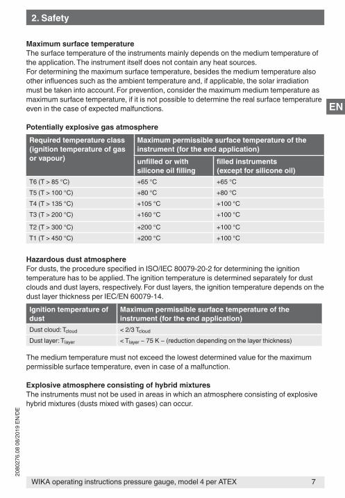
Maximum surface temperatureThe surface temperature of the instruments mainly depends on the medium temperature of the application. The instrument itself does not contain any heat sources.For determining the maximum surface temperature, besides the medium temperature also other influences such as the ambient temperature and, if applicable, the solar irradiation must be taken into account. For prevention, consider the maximum medium temperature as maximum surface temperature, if it is not possible to determine the real surface temperature even in the case of expected malfunctions.
Potentially explosive gas atmosphereRequired temperature class(ignition temperature of gas or vapour)
Maximum permissible surface temperature of the instrument (for the end application)unfilledorwithsiliconeoilfilling
filledinstruments(except for silicone oil)
T6 (T > 85 °C) +65 °C +65 °CT5 (T > 100 °C) +80 °C +80 °CT4 (T > 135 °C) +105 °C +100 °CT3 (T > 200 °C) +160 °C +100 °C
T2 (T > 300 °C) +200 °C +100 °CT1 (T > 450 °C) +200 °C +100 °C
Hazardous dust atmosphereFor dusts, the procedure specified in ISO/IEC 80079-20-2 for determining the ignition temperature has to be applied. The ignition temperature is determined separately for dust clouds and dust layers, respectively. For dust layers, the ignition temperature depends on the dust layer thickness per IEC/EN 60079-14.Ignition temperature of dust
Maximum permissible surface temperature of the instrument (for the end application)
Dust cloud: Tcloud < 2/3 Tcloud
Dust layer: Tlayer < Tlayer − 75 K − (reduction depending on the layer thickness)
The medium temperature must not exceed the lowest determined value for the maximum permissible surface temperature, even in case of a malfunction.
Explosive atmosphere consisting of hybrid mixturesThe instruments must not be used in areas in which an atmosphere consisting of explosive hybrid mixtures (dusts mixed with gases) can occur.
WIKA operating instructions pressure gauge, model 4 per ATEX8
2080
276.
08 0
8/20
19 E
N/D
E
EN
2.5 Special hazards
WARNING!For hazardous media such as oxygen, acetylene, flammable or toxic gases or liquids, and refrigeration plants, compressors, etc., in addition to all stand-ard regulations, the appropriate existing codes or regulations must also be followed.
Instruments with PTFE lining
WARNING!Media which can become electrostatically charged are not permissible for instruments with PTFE lining.
▶ Select media that do not generate any electrostatic charge.
For additional important safety instructions see chapter 2.4 “Specifications and temperature limits”.
WARNING!Residual media in dismounted instruments can result in a risk to persons, the environment and equipment.
▶ Take sufficient precautionary measures.
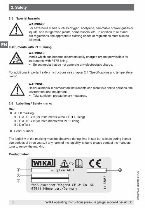
2.6 Labelling / Safety marks
Dial � ATEX marking:
II 2 G c IIC Tx x (for instruments without PTFE lining)II 2 G c IIB Tx x (for instruments with PTFE lining)II 2 D c Tx x
� Serial number
The legibility of the marking must be observed during time in use but at least during inspec-tion periods of three years. If any harm of the legibility is found please contact the manufac-turer to renew the marking.
Product label
2. Safety
9WIKA operating instructions pressure gauge, model 4 per ATEX
2080
276.
08 0
8/20
19 E
N/D
E
EN
Model
Article number
Permissible ambient temperature
Date of manufacture (month/year)
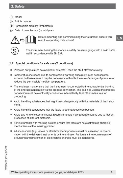
Before mounting and commissioning the instrument, ensure you read the operating instructions!
The instrument bearing this mark is a safety pressure gauge with a solid baffle wall in accordance with EN 837.
2.7 Special conditions for safe use (X conditions)
� Pressure surges must be avoided at all costs. Open the shut-off valves slowly.
� Temperature increases due to compression warming absolutely must be taken into account. In these cases it may be necessary to throttle the rate of change of pressure or reduce the permissible medium temperature.
� The end user must ensure that the instrument is connected to the equipotential bonding of the end-use application via the process connection. The sealings used at the process connection must be electrically conductive. Alternatively, take other measures for grounding.
� Avoid handling substances that might react dangerously with the materials of the instru-ment.
� Avoid handling substances that are liable to spontaneous combustion.
� Avoid any kind of external impact. External impacts may generate sparks due to friction processes of different materials.
� For instruments with marking pointer, ensure that there are no electrostatic charging mechanisms at the marking pointer.
� All accessories (e.g. valves or attachment components) must be assessed in combi-nation with the delivered instruments by the end user. Particularly the requirements of grounding and prevention of electrostatic charges must be considered.
2. Safety
WIKA operating instructions pressure gauge, model 4 per ATEX10
2080
276.
08 0
8/20
19 E
N/D
E
EN
3. SpecificationsPressure limitationModels 4x2.30.1x0, 4x3.30.1x0, 4x2.50.1x0, 4x3.50.1x0:
Steady: Full scale valueFluctuating: 0.9 x full scale valueShort time: 5 x full scale value, however max. 40 bar
Models 4x2.x6.1x0 / 4x3.x6.1x0:Steady: Full scale valueFluctuating: 0.9 x full scale valueShort time: 40, 100 or 400 bar
TemperatureeffectWhen the temperature of the measuring system deviates from the reference temperature (+20 °C):max. ±0.8 %/10 K of full scale value
Case ingress protection 1) (per IEC/EN 60529)IP54 (with liquid filling IP65)
For further specifications see WIKA data sheet PM 04.03, PM 04.07 and the order documentation.1) For general use, no ATEX requirement
4. Design and functionDescription
� Nominal size 100 and 160 mm
� The instruments measure the pressure by means of resilient diaphragm measuring elements.
� The measuring characteristics are in accordance with the EN 837-3 standard.
� In addition, the enclosing components of models 43x.30.1x0 and 43x.36.1x0 also meet the requirements of EN 837-1, relating to safety pressure gauges with a solid baffle wall (code S3).
Scope of deliveryCross-check scope of delivery with delivery note.
3.Specifications/4.Designandfunction
11WIKA operating instructions pressure gauge, model 4 per ATEX
2080
276.
08 0
8/20
19 E
N/D
E
EN
5. Transport, packaging ... / 6. Commissioning, operation
5. Transport, packaging and storage5.1 TransportCheck the instrument for any damage that may have been caused by transport. Obvious damage must be reported immediately.
Shocks can cause small bubbles to form in the fill fluid of filled instruments. This has no effect on the function of the instrument.
5.2 PackagingDo not remove packaging until just before mounting.Keep the packaging as it will provide optimum protection during transport (e.g. change in installation site, sending for repair).
5.3 Storage
Permissible storage temperature-20 ... +70 °C (optional: -40 … +70 °C)
6. Commissioning, operation
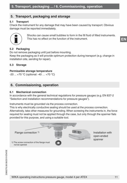
6.1 Mechanical connectionIn accordance with the general technical regulations for pressure gauges (e.g. EN 837-2 “Selection and installation recommendations for pressure gauges”).
Instruments must be grounded via the process connection.This is why electrically conductive sealing should be used at the process connection. Alternatively, take other measures for grounding. When screwing the instruments in, the force required for sealing must not be applied through the case, but only through the spanner flats provided for this purpose, and using a suitable tool.
Installation with open-ended spanner
Flange connection 1)
1) The screw connection of the flange must not be opened
WIKA operating instructions pressure gauge, model 4 per ATEX12
2080
276.
08 0
8/20
19 E
N/D
E
EN
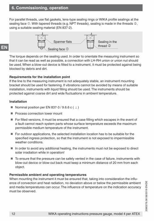
For parallel threads, use flat gaskets, lens-type sealing rings or WIKA profile sealings at the sealing face . With tapered threads (e.g. NPT threads), sealing is made in the threads , using a suitable sealing material (EN 837-2).
The torque depends on the sealing used. In order to orientate the measuring instrument so that it can be read as well as possible, a connection with LH-RH union or union nut should be used. When a blow-out device is fitted to a instrument, it must be protected against being blocked by debris and dirt.
Requirements for the installation pointIf the line to the measuring instrument is not adequately stable, an instrument mounting bracket should be used for fastening. If vibrations cannot be avoided by means of suitable installation, instruments with liquid filling should be used. The instruments should be protected against coarse dirt and wide fluctuations in ambient temperature.
Installation � Nominal position per EN 837-3 / 9.6.6 c ( ⊥ )
� Process connection lower mount
� For filled versions, it must be ensured that a case filling which escapes in the event of a fault cannot reach system parts whose surface temperature exceeds the maximum permissible medium temperature of the instrument.
� For outdoor applications, the selected installation location has to be suitable for the specified ingress protection, so that the instrument is not exposed to impermissible weather conditions.
� In order to avoid any additional heating, the instruments must not be exposed to direct solar irradiation while in operation!
� To ensure that the pressure can be safely vented in the case of failure, instruments with blow-out device or blow-out back must keep a minimum distance of 20 mm from each object.
Permissible ambient and operating temperaturesWhen mounting the instrument it must be ensured that, taking into consideration the influ-ence of convection and heat radiation, no deviation above or below the permissible ambient and media temperatures can occur. The influence of temperature on the indication accuracy must be observed.
Sealing in the thread
Spanner flats
Sealing face
6. Commissioning, operation
13WIKA operating instructions pressure gauge, model 4 per ATEX
2080
276.
08 0
8/20
19 E
N/D
E
EN
WARNING!The actual maximum surface temperature depends not on the equipment itself, but mainly on the operating conditions. With gaseous substances, the temperature may increase as a result of compression warming. In these cases it may be necessary to throttle the rate of change of pressure or reduce the permissible medium temperature.
Permissible vibration load at the installation siteThe instruments should always be installed in locations free from vibration.If necessary, it is possible to isolate the instrument from the mounting point, e.g. by installing a flexible connection line between the measuring point and the instrument and mounting the instrument on a suitable bracket.If this is not possible, the following limit values must not be exceeded:
Frequency range < 150 HzAcceleration < 0.5 g (5 m/s2)
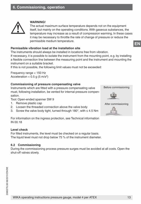
Commissioning of pressure compensating valveInstruments which are fitted with a pressure compensating valve must, following installation, be vented for internal pressure compen-sation.Tool: Open-ended spanner SW 91. Remove plastic cap2. Loosen the threaded connection above the valve body3. Screw the valve body tight, turned through 180°, with ≤ 4.5 Nm
For information on the ingress protection, see Technical information IN 00.18
Level checkFor filled instruments, the level must be checked on a regular basis.The liquid level must not drop below 75 % of the instrument diameter.
6.2 CommissioningDuring the commissioning process pressure surges must be avoided at all costs. Open the shut-off valves slowly.
After commissioning
Before commissioning
6. Commissioning, operation
WIKA operating instructions pressure gauge, model 4 per ATEX14
2080
276.
08 0
8/20
19 E
N/D
E
EN
7. Maintenance and cleaning
7.1 MaintenanceThe instruments are maintenance-free. The indicator should be checked once or twice every year. For this the instrument must be disconnected from the process to check with a pressure testing device.
WARNING!Dangertolifeduetoimpermissiblefilling/refillingoftheinstrumentwith loss of explosion protectionThe filling/refilling of instruments by non-authorised personnel leads to a loss of the explosion protection and can lead to damage to the instrument.
▶ Repair of the instruments may only be carried out by authorised bodies.
If the instrument is exposed to intensive UV radiation, the colouring of the dial printing may change. This has no effect on the function of the instrument.
7.2 Cleaning
CAUTION! � Clean the instrument with a moist cloth. Ensure that due to the cleaning no
electrostatic charge will be generated.
� Wash or clean the dismounted instrument before returning it, in order to protect persons and the environment from exposure to residual media.
8. Dismounting and disposal
WARNING!Residual media in dismounted instruments can result in a risk to persons, the environment and equipment.Take sufficient precautionary measures.
8.1 DismountingOnly disconnect the instrument once the system has been depressurised!
8.2 DisposalIncorrect disposal can put the environment at risk.
Dispose of instrument components and packaging materials in an environmentally compati-ble way and in accordance with the country-specific waste disposal regulations.
7. Maintenance and cleaning / 8. Dismounting and disposal
15WIKA operating instructions pressure gauge, model 4 per ATEX
2080
276.
08 0
8/20
19 E
N/D
E
EN
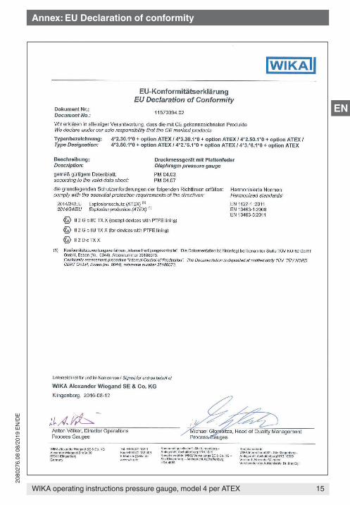
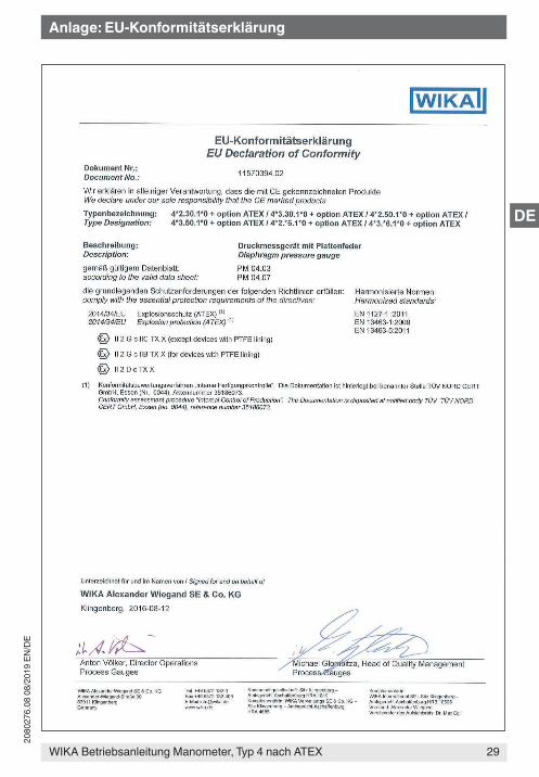
Annex: EU Declaration of conformity

WIKA operating instructions pressure gauge, model 4 per ATEX16
2080
276.
08 0
8/20
19 E
N/D
E
EN
17WIKA Betriebsanleitung Manometer, Typ 4 nach ATEX
2080
276.
08 0
8/20
19 E
N/D
E
DE
InhaltInhalt
Konformitätserklärungen finden Sie online unter www.wika.de.
1. Allgemeines 182. Sicherheit 19
2.1 Bestimmungsgemäße Verwendung . . . . . . . . . . . . . .192.2 Verantwortung des Betreibers . . . . . . . . . . . . . . . .192.3 Personalqualifikation . . . . . . . . . . . . . . . . . . .202.4 Spezifikation und Temperaturgrenzen. . . . . . . . . . . . . .202.5 Besondere Gefahren . . . . . . . . . . . . . . . . . . .222.6 Beschilderung / Sicherheitskennzeichnungen . . . . . . . . . . .222.7 Besondere Bedingungen für die sichere Verwendung (x-Conditions) . . .23
3. Technische Daten 244. Aufbau und Funktion 245. Transport, Verpackung und Lagerung 25
5.1 Transport . . . . . . . . . . . . . . . . . . . . . . .255.2 Verpackung . . . . . . . . . . . . . . . . . . . . . .255.3 Lagerung . . . . . . . . . . . . . . . . . . . . . . .25
6. Inbetriebnahme, Betrieb 256.1 Mechanischer Anschluss . . . . . . . . . . . . . . . . . .256.2 Inbetriebnahme . . . . . . . . . . . . . . . . . . . . .27
7. Wartung und Reinigung 287.1 Wartung. . . . . . . . . . . . . . . . . . . . . . . .287.2 Reinigung . . . . . . . . . . . . . . . . . . . . . . .28
8. Demontage und Entsorgung 288.1 Demontage . . . . . . . . . . . . . . . . . . . . . .288.2 Entsorgung . . . . . . . . . . . . . . . . . . . . . .28
Anlage: EU-Konformitätserklärung 29
WIKA Betriebsanleitung Manometer, Typ 4 nach ATEX18
2080
276.
08 0
8/20
19 E
N/D
E
DE
1. Allgemeines
1. Allgemeines � Das in der Betriebsanleitung beschriebene Gerät wird nach den neuesten Erkenntnissen
konstruiert und gefertigt. Alle Komponenten unterliegen während der Fertigung strengen Qualitäts- und Umweltkriterien. Unsere Managementsysteme sind nach ISO 9001 und ISO 14001 zertifiziert.
� Diese Betriebsanleitung gibt wichtige Hinweise zum Umgang mit dem Gerät. Vorausset-zung für sicheres Arbeiten ist die Einhaltung aller angegebenen Sicherheitshinweise und Handlungsanweisungen.
� Die für den Einsatzbereich des Gerätes geltenden örtlichen Unfallverhütungsvorschriften und allgemeinen Sicherheitsbestimmungen einhalten.
� Die Betriebsanleitung ist Produktbestandteil und muss in unmittelbarer Nähe des Gerätes für das Fachpersonal jederzeit zugänglich aufbewahrt werden.
� Das Fachpersonal muss die Betriebsanleitung vor Beginn aller Arbeiten sorgfältig durch-gelesen und verstanden haben.
� Die Haftung des Herstellers erlischt bei Schäden durch bestimmungswidrige Verwen-dung, Nichtbeachten dieser Betriebsanleitung, Einsatz ungenügend qualifizierten Fachpersonals sowie eigenmächtiger Veränderung am Gerät.
� Es gelten die allgemeinen Geschäftsbedingungen in den Verkaufsunterlagen. � Technische Änderungen vorbehalten. � Weitere Informationen:
- Internet-Adresse: www.wika.de / www.wika.com- zugehöriges Datenblatt: PM 04.03, PM 04.07
Symbolerklärung
WARNUNG!… weist auf eine möglicherweise gefährliche Situation hin, die zum Tod oder zu schweren Verletzungen führen kann, wenn sie nicht gemieden wird.
Information… hebt nützliche Tipps und Empfehlungen sowie Informationen für einen effizienten und störungsfreien Betrieb hervor.
WARNUNG!… weist auf eine möglicherweise gefährliche Situation im explosionsgefährdeten Bereich hin, die zum Tod oder zu schweren Verletzungen führt, wenn sie nicht gemieden wird.
19WIKA Betriebsanleitung Manometer, Typ 4 nach ATEX
2080
276.
08 0
8/20
19 E
N/D
E
DE
2. Sicherheit
2. SicherheitWARNUNG!Vor Montage, Inbetriebnahme und Betrieb sicherstellen, dass das richtige Gerät hinsichtlich Messbereich, Ausführung und spezifischen Messbedingun-gen ausgewählt wurde.Verträglichkeit der druckbelasteten Werkstoffe mit dem Messstoff prüfen!Die Belastungsgrenzen sind einzuhalten, um die Messgenauigkeit und die Lebensdauer zu gewährleisten.
▶ Bei Nichtbeachten können schwere Körperverletzungen und/oder Sachschäden auftreten.
Weitere wichtige Sicherheitshinweise befinden sich in den einzelnen Kapiteln dieser Betriebsanleitung.
2.1 Bestimmungsgemäße VerwendungDiese Manometer dienen zum Messen von Druck bei industriellen Anwendungen in explosi-onsgefährdeten Bereichen.
Das Gerät ist ausschließlich für den hier beschriebenen bestimmungsgemäßen Verwen-dungszweck konzipiert und konstruiert und darf nur dementsprechend verwendet werden.
Ansprüche jeglicher Art aufgrund von nicht bestimmungsgemäßer Verwendung sind ausge-schlossen.
2.2 Verantwortung des BetreibersDas Gerät wird im gewerblichen Bereich eingesetzt. Der Betreiber unterliegt daher den gesetzlichen Pflichten zur Arbeitssicherheit.
Die Sicherheitshinweise dieser Betriebsanleitung, sowie die für den Einsatzbereich des Gerätes gültigen Sicherheits-, Unfallverhütungs- und Umweltschutzvorschriften einhalten.
Der Betreiber ist verpflichtet das Typenschild lesbar zu halten.
Für ein sicheres Arbeiten am Gerät muss der Betreiber sicherstellen, � dass eine entsprechende Erste-Hilfe-Ausrüstung vorhanden ist und bei Bedarf jederzeit
Hilfe zur Stelle ist. � dass das Bedienpersonal regelmäßig in allen zutreffenden Fragen von Arbeitssicherheit,
Erste Hilfe und Umweltschutz unterwiesen wird, sowie die Betriebsanleitung und insbe-sondere die darin enthaltenen Sicherheitshinweise kennt.
� dass das Gerät gemäß der bestimmungsgemäßen Verwendung für den Anwendungsfall geeignet ist.
� dass die persönliche Schutzausrüstung verfügbar ist.
WIKA Betriebsanleitung Manometer, Typ 4 nach ATEX20
2080
276.
08 0
8/20
19 E
N/D
E
DE
An den messstoffberührten Teilen des Gerätes können herstellungsbedingt geringe Restmengen des Justagemediums (z. B. Druckluft, Wasser, Öl) anhaften. Bei erhöhten Anforderungen an die technische Sauberkeit muss die Eignung für den Anwendungsfall vor Inbetriebnahme vom Betreiber geprüft sein.
2.3 Personalqualifikation
WARNUNG!VerletzungsgefahrbeiunzureichenderQualifikation!Unsachgemäßer Umgang kann zu erheblichen Personen- und Sachschäden führen.
▶ Die in dieser Betriebsanleitung beschriebenen Tätigkeiten nur durch Fachpersonal nachfolgend beschriebener Qualifikation durchführen lassen.
FachpersonalDas Fachpersonal ist aufgrund seiner fachlichen Ausbildung, seiner Kenntnisse der Mess- und Regelungstechnik und seiner Erfahrungen sowie Kenntnis der landesspezifischen Vorschriften, geltenden Normen und Richtlinien in der Lage, die beschriebenen Arbeiten auszuführen und mögliche Gefahren selbstständig zu erkennen.
Besondere Kenntnisse bei Arbeiten mit Geräten für explosionsgefährdete Bereiche:Das Fachpersonal muss Kenntnisse haben über Zündschutzarten, Vorschriften und Verord-nungen für Betriebsmittel in explosionsgefährdeten Bereichen.
2.4 Spezifikation und Temperaturgrenzen
WARNUNG!Die Nichtbeachtung dieser Inhalte und Anweisungen kann zum Verlust des Explosionsschutzes führen.
WARNUNG!Einsatzbedingungen und sicherheitstechnische Daten der EU-Baumusterprüfbescheinigung unbedingt beachten.
▶ Geräte müssen über den Prozessanschluss geerdet sein.
Zulässige Umgebungstemperatur-20 ... +60 °C-40 ... +60 °C (optional, nur mit Silikonölfüllung)
ZulässigeMessstofftemperatur-20 ... +100 °C-20 ... +200 °C (optional, ungefüllte Geräte oder mit Silikonölfüllung)
2. Sicherheit
21WIKA Betriebsanleitung Manometer, Typ 4 nach ATEX
2080
276.
08 0
8/20
19 E
N/D
E
DE
2. Sicherheit
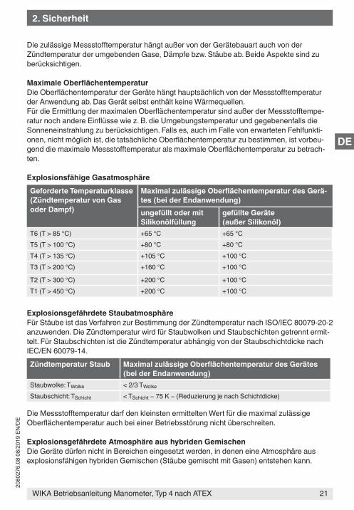
Die zulässige Messstofftemperatur hängt außer von der Gerätebauart auch von der Zündtemperatur der umgebenden Gase, Dämpfe bzw. Stäube ab. Beide Aspekte sind zu berücksichtigen.
MaximaleOberflächentemperaturDie Oberflächentemperatur der Geräte hängt hauptsächlich von der Messstofftemperatur der Anwendung ab. Das Gerät selbst enthält keine Wärmequellen.Für die Ermittlung der maximalen Oberflächentemperatur sind außer der Messstofftempe-ratur noch andere Einflüsse wie z. B. die Umgebungstemperatur und gegebenenfalls die Sonneneinstrahlung zu berücksichtigen. Falls es, auch im Falle von erwarteten Fehlfunkti-onen, nicht möglich ist, die tatsächliche Oberflächentemperatur zu bestimmen, ist vorbeu-gend die maximale Messstofftemperatur als maximale Oberflächentemperatur zu betrach-ten.
Explosionsfähige GasatmosphäreGeforderte Temperaturklasse(Zündtemperatur von Gas oder Dampf)
MaximalzulässigeOberflächentemperaturdesGerä-tes (bei der Endanwendung)ungefüllt oder mit Silikonölfüllung
gefüllte Geräte (außer Silikonöl)
T6 (T > 85 °C) +65 °C +65 °CT5 (T > 100 °C) +80 °C +80 °CT4 (T > 135 °C) +105 °C +100 °CT3 (T > 200 °C) +160 °C +100 °C
T2 (T > 300 °C) +200 °C +100 °CT1 (T > 450 °C) +200 °C +100 °C
Explosionsgefährdete StaubatmosphäreFür Stäube ist das Verfahren zur Bestimmung der Zündtemperatur nach ISO/IEC 80079-20-2 anzuwenden. Die Zündtemperatur wird für Staubwolken und Staubschichten getrennt ermit-telt. Für Staubschichten ist die Zündtemperatur abhängig von der Staubschichtdicke nach IEC/EN 60079-14.Zündtemperatur Staub MaximalzulässigeOberflächentemperaturdesGerätes
(bei der Endanwendung)Staubwolke: TWolke < 2/3 TWolke
Staubschicht: TSchicht < TSchicht − 75 K − (Reduzierung je nach Schichtdicke)
Die Messstofftemperatur darf den kleinsten ermittelten Wert für die maximal zulässige Oberflächentemperatur auch bei einer Betriebsstörung nicht überschreiten.
Explosionsgefährdete Atmosphäre aus hybriden GemischenDie Geräte dürfen nicht in Bereichen eingesetzt werden, in denen eine Atmosphäre aus explosionsfähigen hybriden Gemischen (Stäube gemischt mit Gasen) entstehen kann.
WIKA Betriebsanleitung Manometer, Typ 4 nach ATEX22
2080
276.
08 0
8/20
19 E
N/D
E
DE
2.5 Besondere Gefahren
WARNUNG!Bei gefährlichen Messstoffen wie z. B. Sauerstoff, Acetylen, brennbaren oder giftigen Stoffen, sowie bei Kälteanlagen, Kompressoren etc. müssen über die gesamten allgemeinen Regeln hinaus die jeweils bestehenden einschlägigen Vorschriften beachtet werden.
Geräte mit PTFE-Auskleidung
WARNUNG!Messstoffe, die sich elektrostatisch aufladen können, sind für Geräte mit PTFE-Auskleidung nicht zulässig.
▶ Messstoffe wählen, die keine elektrostatische Aufladung erzeugen.
Weitere wichtige Sicherheitshinweise siehe Kapitel „2.4 Spezifikation und Temperaturgren-zen“.
WARNUNG!Messstoffreste in ausgebauten Geräten können zur Gefährdung von Perso-nen, Umwelt und Einrichtung führen.
▶ Ausreichende Vorsichtsmaßnahmen ergreifen.
2.6 Beschilderung / Sicherheitskennzeichnungen
Zifferblatt � ATEX Kennzeichnung:
II 2 G c IIC Tx x (für Geräte ohne PTFE-Auskleidung)II 2 G c IIB Tx x (für Geräte mit PTFE-Auskleidung)II 2 D c Tx x
� Seriennummer
Die Lesbarkeit der Kennzeichnung muss während der Dauer der Verwendung, jedoch mindestens während eines Prüfzeitraums von drei Jahren kontrolliert werden. Sollte die Lesbarkeit beeinträchtigt sein, den Hersteller bitten, die Kennzeichnung zu erneuern.
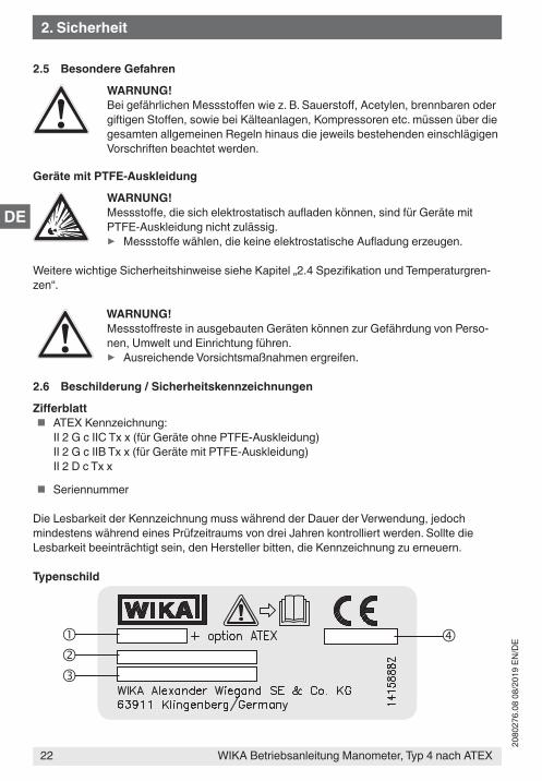
Typenschild
2. Sicherheit
23WIKA Betriebsanleitung Manometer, Typ 4 nach ATEX
2080
276.
08 0
8/20
19 E
N/D
E
DE
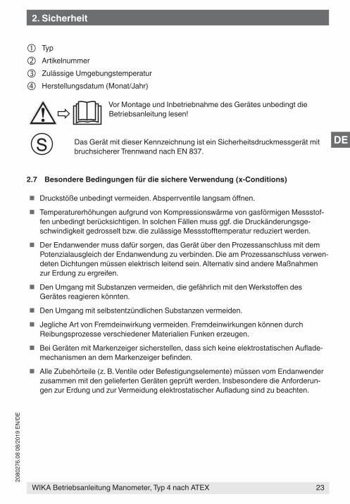
Typ
Artikelnummer
Zulässige Umgebungstemperatur
Herstellungsdatum (Monat/Jahr)
Vor Montage und Inbetriebnahme des Gerätes unbedingt die Betriebsanleitung lesen!
Das Gerät mit dieser Kennzeichnung ist ein Sicherheitsdruckmessgerät mit bruchsicherer Trennwand nach EN 837.
2.7 Besondere Bedingungen für die sichere Verwendung (x-Conditions)
� Druckstöße unbedingt vermeiden. Absperrventile langsam öffnen.
� Temperaturerhöhungen aufgrund von Kompressionswärme von gasförmigen Messstof-fen unbedingt berücksichtigen. In solchen Fällen muss ggf. die Druckänderungsge-schwindigkeit gedrosselt bzw. die zulässige Messstofftemperatur reduziert werden.
� Der Endanwender muss dafür sorgen, das Gerät über den Prozessanschluss mit dem Potenzialausgleich der Endanwendung zu verbinden. Die am Prozessanschluss verwen-deten Dichtungen müssen elektrisch leitend sein. Alternativ sind andere Maßnahmen zur Erdung zu ergreifen.
� Den Umgang mit Substanzen vermeiden, die gefährlich mit den Werkstoffen des Gerätes reagieren könnten.
� Den Umgang mit selbstentzündlichen Substanzen vermeiden.
� Jegliche Art von Fremdeinwirkung vermeiden. Fremdeinwirkungen können durch Reibungsprozesse verschiedener Materialien Funken erzeugen.
� Bei Geräten mit Markenzeiger sicherstellen, dass sich keine elektrostatischen Auflade-mechanismen an dem Markenzeiger befinden.
� Alle Zubehörteile (z. B. Ventile oder Befestigungselemente) müssen vom Endanwender zusammen mit den gelieferten Geräten geprüft werden. Insbesondere die Anforderun-gen zur Erdung und zur Vermeidung elektrostatischer Aufladung sind zu beachten.
2. Sicherheit
WIKA Betriebsanleitung Manometer, Typ 4 nach ATEX24
2080
276.
08 0
8/20
19 E
N/D
E
DE
3. Technische DatenDruckbelastbarkeitTypen 4x2.30.1x0, 4x3.30.1x0, 4x2.50.1x0, 4x3.50.1x0:
Ruhebelastung: SkalenendwertWechselbelastung: 0,9 x Skalenendwertkurzzeitig: 5 x Skalenendwert, jedoch max. 40 bar
Typen 4x2.x6.1x0 / 4x3.x6.1x0:Ruhebelastung: SkalenendwertWechselbelastung: 0,9 x Skalenendwertkurzzeitig: 40, 100 oder 400 bar
TemperatureinflussBei Abweichung von der Referenztemperatur am Messsystem (+20 °C):max. ±0,8 %/10 K vom jeweiligen Skalenendwert
Gehäuseschutzart 1) (nach IEC/EN 60529)IP54 (mit Flüssigkeitsfüllung IP65)
Weitere technische Daten siehe WIKA Datenblatt PM 04.03, PM 04.07 und Bestellunterlagen.1) Für allgemeinen Gebrauch, keine ATEX-Anforderung
4. Aufbau und FunktionBeschreibung
� Nenngröße 100 und 160 mm
� Die Geräte erfassen den zu messenden Druck mit elastischen Plattenfeder-Messglie-dern.
� Die messtechnischen Eigenschaften entsprechen der Norm EN 837-3.
� Die umhüllenden Bauteile der Typen 43x.30.1x0 und 43x.36.1x0 erfüllen außerdem die Anforderungen der EN 837-1 an Sicherheitsdruckmessgeräte mit bruchsicherer Trenn-wand (Kurzzeichen S3).
LieferumfangLieferumfang mit dem Lieferschein abgleichen.
3. Technische Daten / 4. Aufbau und Funktion
25WIKA Betriebsanleitung Manometer, Typ 4 nach ATEX
2080
276.
08 0
8/20
19 E
N/D
E
DE
5. Transport, Verpackung ... / 6. Inbetriebnahme, Betrieb
5. Transport, Verpackung und Lagerung5.1 TransportGerät auf eventuell vorhandene Transportschäden untersuchen. Offensichtliche Schäden unverzüglich mitteilen.
Durch Erschütterungen können sich bei gefüllten Geräten in der Füllflüssig-keit kleine Bläschen bilden. Dies hat keinen Einfluss auf die Funktion des Gerätes.
5.2 VerpackungVerpackung erst unmittelbar vor der Montage entfernen.Die Verpackung aufbewahren, denn diese bietet bei einem Transport einen optimalen Schutz (z. B. wechselnder Einbauort, Reparatursendung).
5.3 Lagerung
Zulässige Lagertemperatur-20 ... +70 °C (optional: -40 … +70 °C)
6. Inbetriebnahme, Betrieb
6.1 Mechanischer AnschlussEntsprechend den allgemeinen technischen Regeln für Manometer (z. B. EN 837-2 „Auswahl- und Einbauempfehlungen für Manometer“).
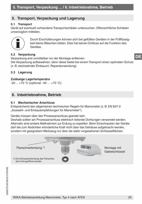
Geräte müssen über den Prozessanschluss geerdet sein.Deshalb sollten am Prozessanschluss elektrisch leitende Dichtungen verwendet werden. Alternativ sind andere Maßnahmen zur Erdung zu ergreifen. Beim Einschrauben der Geräte darf die zum Abdichten erforderliche Kraft nicht über das Gehäuse aufgebracht werden, sondern mit geeignetem Werkzeug nur über die dafür vorgesehenen Schlüsselflächen.
Montage mit Gabelschlüssel
Flanschverbindung 1)
1) Die Schraubverbindung des Flansches darf nicht geöffnet werden
WIKA Betriebsanleitung Manometer, Typ 4 nach ATEX26
2080
276.
08 0
8/20
19 E
N/D
E
DE
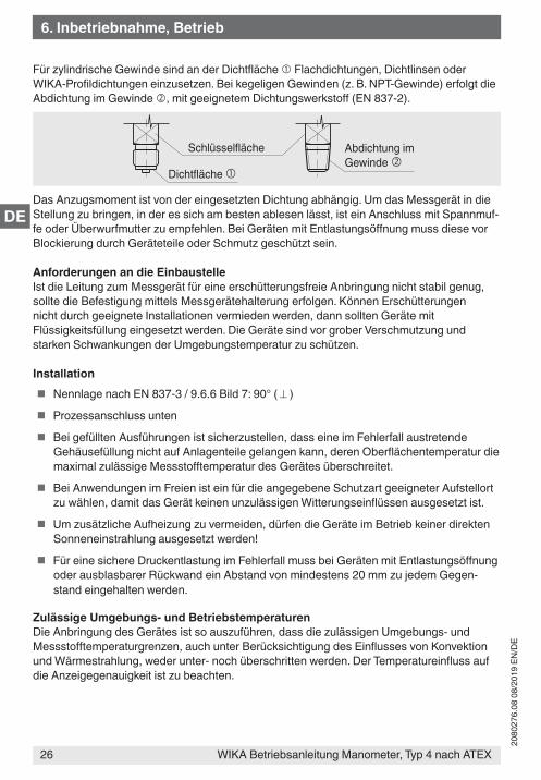
Für zylindrische Gewinde sind an der Dichtfläche Flachdichtungen, Dichtlinsen oder WIKA-Profildichtungen einzusetzen. Bei kegeligen Gewinden (z. B. NPT-Gewinde) erfolgt die Abdichtung im Gewinde , mit geeignetem Dichtungswerkstoff (EN 837-2).
Das Anzugsmoment ist von der eingesetzten Dichtung abhängig. Um das Messgerät in die Stellung zu bringen, in der es sich am besten ablesen lässt, ist ein Anschluss mit Spannmuf-fe oder Überwurfmutter zu empfehlen. Bei Geräten mit Entlastungsöffnung muss diese vor Blockierung durch Geräteteile oder Schmutz geschützt sein.
Anforderungen an die EinbaustelleIst die Leitung zum Messgerät für eine erschütterungsfreie Anbringung nicht stabil genug, sollte die Befestigung mittels Messgerätehalterung erfolgen. Können Erschütterungen nicht durch geeignete Installationen vermieden werden, dann sollten Geräte mit Flüssigkeitsfüllung eingesetzt werden. Die Geräte sind vor grober Verschmutzung und starken Schwankungen der Umgebungstemperatur zu schützen.
Installation � Nennlage nach EN 837-3 / 9.6.6 Bild 7: 90° ( ⊥ )
� Prozessanschluss unten
� Bei gefüllten Ausführungen ist sicherzustellen, dass eine im Fehlerfall austretende Gehäusefüllung nicht auf Anlagenteile gelangen kann, deren Oberflächentemperatur die maximal zulässige Messstofftemperatur des Gerätes überschreitet.
� Bei Anwendungen im Freien ist ein für die angegebene Schutzart geeigneter Aufstellort zu wählen, damit das Gerät keinen unzulässigen Witterungseinflüssen ausgesetzt ist.
� Um zusätzliche Aufheizung zu vermeiden, dürfen die Geräte im Betrieb keiner direkten Sonneneinstrahlung ausgesetzt werden!
� Für eine sichere Druckentlastung im Fehlerfall muss bei Geräten mit Entlastungsöffnung oder ausblasbarer Rückwand ein Abstand von mindestens 20 mm zu jedem Gegen-stand eingehalten werden.
Zulässige Umgebungs- und BetriebstemperaturenDie Anbringung des Gerätes ist so auszuführen, dass die zulässigen Umgebungs- und Messstofftemperaturgrenzen, auch unter Berücksichtigung des Einflusses von Konvektion und Wärmestrahlung, weder unter- noch überschritten werden. Der Temperatureinfluss auf die Anzeigegenauigkeit ist zu beachten.
Abdichtung im Gewinde
Schlüsselfläche
Dichtfläche
6. Inbetriebnahme, Betrieb
27WIKA Betriebsanleitung Manometer, Typ 4 nach ATEX
2080
276.
08 0
8/20
19 E
N/D
E
DE
WARNUNG!Die tatsächliche maximale Oberflächentemperatur hängt nicht vom Gerät selbst ab, sondern hauptsächlich von den Betriebsbedingungen. Bei gasför-migen Stoffen kann sich die Temperatur durch Kompressionswärme erhöhen. In solchen Fällen muss ggf. die Druckänderungsgeschwindigkeit gedrosselt bzw. die zulässige Messstofftemperatur reduziert werden.
Zulässige Schwingungsbelastung am EinbauortDie Geräte sollten grundsätzlich nur an Stellen ohne Schwingungsbelastung eingebaut werden.Gegebenenfalls kann z. B. durch eine flexible Verbindungsleitung von der Messstelle zum Gerät und die Befestigung über eine Messgerätehalterung eine Entkopplung vom Einbauort erreicht werden.Falls dies nicht möglich ist, dürfen folgende Grenzwerte nicht überschritten werden:
Frequenzbereich < 150 HzBeschleunigung < 0,5 g (5 m/s2)
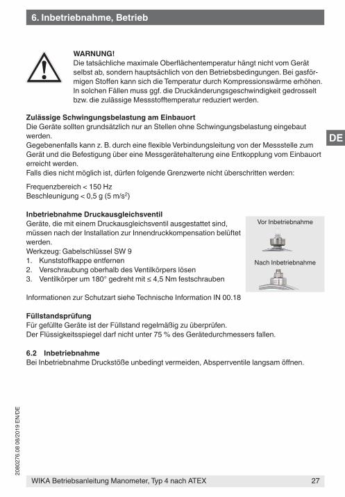
Inbetriebnahme DruckausgleichsventilGeräte, die mit einem Druckausgleichsventil ausgestattet sind, müssen nach der Installation zur Innendruckkompensation belüftet werden.Werkzeug: Gabelschlüssel SW 91. Kunststoffkappe entfernen2. Verschraubung oberhalb des Ventilkörpers lösen3. Ventilkörper um 180° gedreht mit ≤ 4,5 Nm festschrauben
Informationen zur Schutzart siehe Technische Information IN 00.18
FüllstandsprüfungFür gefüllte Geräte ist der Füllstand regelmäßig zu überprüfen.Der Flüssigkeitsspiegel darf nicht unter 75 % des Gerätedurchmessers fallen.
6.2 InbetriebnahmeBei Inbetriebnahme Druckstöße unbedingt vermeiden, Absperrventile langsam öffnen.
Nach Inbetriebnahme
Vor Inbetriebnahme
6. Inbetriebnahme, Betrieb
WIKA Betriebsanleitung Manometer, Typ 4 nach ATEX28
2080
276.
08 0
8/20
19 E
N/D
E
DE
7. Wartung und Reinigung
7.1 WartungDie Geräte sind wartungsfrei. Eine Überprüfung der Anzeige sollte etwa 1 bis 2 mal pro Jahr erfolgen. Dazu ist das Gerät vom Prozess zu trennen und mit einer Druckprüfvorrichtung zu kontrollieren.
WARNUNG!Lebensgefahr durch unzulässiges Füllen/Nachfüllen des Gerätes mit Verlust des ExplosionsschutzesDas Füllen/Nachfüllen von Geräten von nicht-autorisierten Personen führt zum Verlust des Explosionsschutzes und kann zur Beschädigung des Gerätes führen.
▶ Instandsetzung der Geräte nur durch autorisierte Stellen durchführen lassen.
Wird das Gerät intensiver UV-Strahlung ausgesetzt, kann sich die Farbge-bung der Zifferblattbedruckung verändern. Dies hat keinen Einfluss auf die Funktion des Gerätes.
7.2 Reinigung
VORSICHT! � Das Gerät mit einem feuchten Tuch reinigen. Darauf achten, dass durch
die Reinigung keine elektrostatische Aufladung erzeugt wird.
� Ausgebautes Gerät vor der Rücksendung spülen bzw. säubern, um Personen und Umwelt vor Gefährdung durch anhaftende Messstoffreste zu schützen.
8. Demontage und Entsorgung
WARNUNG!Messstoffreste in ausgebauten Geräten können zur Gefährdung von Perso-nen, Umwelt und Einrichtung führen.Ausreichende Vorsichtsmaßnahmen ergreifen.
8.1 DemontageGerät nur im drucklosen Zustand demontieren!
8.2 EntsorgungDurch falsche Entsorgung können Gefahren für die Umwelt entstehen.
Gerätekomponenten und Verpackungsmaterialien entsprechend den landesspezifischen Abfallbehandlungs- und Entsorgungsvorschriften umweltgerecht entsorgen.
7. Wartung und Reinigung / 8. Demontage und Entsorgung
29WIKA Betriebsanleitung Manometer, Typ 4 nach ATEX
2080
276.
08 0
8/20
19 E
N/D
E
DE
Anlage: EU-Konformitätserklärung

WIKA Betriebsanleitung Manometer, Typ 4 nach ATEX30
2080
276.
08 0
8/20
19 E
N/D
E
DE

31
2080
276.
08 0
8/20
19 E
N/D
E
WIKA operating instructions pressure gauge, model 4 per ATEX
2080
276.
08 0
8/20
19 E
N/D
E
32
WIKA Alexander Wiegand SE & Co. KGAlexander-Wiegand-Straße 3063911 Klingenberg • GermanyTel. +49 9372/132-0Fax +49 9372/[email protected]
WIKA operating instructions pressure gauge, model 4 per ATEX
WIKA subsidiaries worldwide can be found online at www.wika.com.WIKA-Niederlassungen weltweit finden Sie online unter www.wika.de.


![DIGITAL DIFFERENTIAL COMPACT PRESSURE TRANSMITTER Digital Pressure Gauge … · 2019. 12. 3. · PRESSURE GAUGE Digital Pressure Gauge & Digital Manometer [Input setting 2 ] SETTING](https://img.pdfslide.us/doc/110x75/60b001340dff284ff85b02be/digital-differential-compact-pressure-transmitter-digital-pressure-gauge-2019-12.jpg)