Embed Size (px)
Citation preview
Operating instructionsBetriebsanleitungManuale d'uso
EN
DE
IT
Dead-weight tester as high pressure version, model CPB3800HP
Druckwaage als Hochdruckausführung, Typ CPB3800HP
Bilancia a presi per alte pressioni, modello CPB3800HP
Dead-weight tester as high pressure version, model CPB3800HP
2
1413
2099
.01
06/2
016
EN/D
E/IT
WIKA operating instructions, model CPB3800HP
EN
DE
IT
Operating instructions model CPB3800HP Page 3 - 49
Betriebsanleitung Typ CPB3800HP Seite 51 - 97
Manuale d'uso modello CPB3800HP Pagina 99 - 145
Further languages can be found at www.wika.com.
© 06/2016 WIKA Alexander Wiegand SE & Co. KGAll rights reserved. / Alle Rechte vorbehalten.WIKA® is a registered trademark in various countries.WIKA® ist eine geschützte Marke in verschiedenen Ländern.
Prior to starting any work, read the operating instructions!Keep for later use!
Vor Beginn aller Arbeiten Betriebsanleitung lesen!Zum späteren Gebrauch aufbewahren!
Prima di iniziare ad utilizzare lo strumento, leggere il manuale d’uso!Conservare per future consultazioni!
3WIKA operating instructions, model CPB3800HP
1413
2099
.01
06/2
016
EN/D
E/IT
EN1. General information 52. Safety 6
2.1 Explanation of symbols . . . . . . . . . . . . . . . . . . . 62.2 Intended use. . . . . . . . . . . . . . . . . . . . . . . 62.3 Improper use . . . . . . . . . . . . . . . . . . . . . . 7
2.3.1 Handling of mineral oils . . . . . . . . . . . . . . . . . 82.3.2 Other liquids . . . . . . . . . . . . . . . . . . . . . 92.3.3 Lifting of masses . . . . . . . . . . . . . . . . . . . 9
2.4 Personnel qualification . . . . . . . . . . . . . . . . . . . 92.5 Personal protective equipment. . . . . . . . . . . . . . . . . 102.6 Labelling, safety marks . . . . . . . . . . . . . . . . . . . 11
3. Design and function 123.1 Description . . . . . . . . . . . . . . . . . . . . . . . 123.2 Scope of delivery . . . . . . . . . . . . . . . . . . . . . 123.3 Base . . . . . . . . . . . . . . . . . . . . . . . . . 12
3.3.1 Spindle pump . . . . . . . . . . . . . . . . . . . . 143.3.2 Reservoir . . . . . . . . . . . . . . . . . . . . . . 143.3.3 Control valves . . . . . . . . . . . . . . . . . . . . 143.3.4 Connection blocks . . . . . . . . . . . . . . . . . . . 14
3.4 Piston unit . . . . . . . . . . . . . . . . . . . . . . . 153.5 Functions . . . . . . . . . . . . . . . . . . . . . . . . 16
4. Transport, packaging and storage 174.1 Transport . . . . . . . . . . . . . . . . . . . . . . . . 174.2 Packaging and storage . . . . . . . . . . . . . . . . . . . 17
5. Commissioning, operation 185.1 Unpacking the dead-weight tester . . . . . . . . . . . . . . . 185.2 Ambient conditions . . . . . . . . . . . . . . . . . . . . 195.3 Installing the base . . . . . . . . . . . . . . . . . . . . . 195.4 Assembly of the dead-weight tester . . . . . . . . . . . . . . . 19
5.4.1 Filling the base with liquid . . . . . . . . . . . . . . . . 205.4.2 Post-assembly test . . . . . . . . . . . . . . . . . . 20
5.5 Procedure . . . . . . . . . . . . . . . . . . . . . . . 215.5.1 Pressure loading . . . . . . . . . . . . . . . . . . . 225.5.2 During calibration . . . . . . . . . . . . . . . . . . . 225.5.3 Reference values . . . . . . . . . . . . . . . . . . . 23
5.6 Completion . . . . . . . . . . . . . . . . . . . . . . . 245.7 Temperature measurement of piston . . . . . . . . . . . . . . 245.8 Cleaning the measuring instruments. . . . . . . . . . . . . . . 25
Contents
Contents
4 WIKA operating instructions, model CPB3800HP
1413
2099
.01
06/2
016
EN/D
E/IT
EN
Contents
6. Faults 267. Maintenance, cleaning and recalibration 30
7.1 Periodic maintenance. . . . . . . . . . . . . . . . . . . . 307.2 Corrective maintenance . . . . . . . . . . . . . . . . . . . 30
7.2.1 General information . . . . . . . . . . . . . . . . . . 307.2.2 Removing the cover . . . . . . . . . . . . . . . . . . 327.2.3 Reservoir seals . . . . . . . . . . . . . . . . . . . . 327.2.4 Valve seals . . . . . . . . . . . . . . . . . . . . . 327.2.5 Spindle pump . . . . . . . . . . . . . . . . . . . . 327.2.6 Star handle assembly. . . . . . . . . . . . . . . . . . 337.2.7 Piston-cylinder system . . . . . . . . . . . . . . . . . 33
7.3 Cleaning . . . . . . . . . . . . . . . . . . . . . . . . 347.4 Recalibration. . . . . . . . . . . . . . . . . . . . . . . 35
7.4.1 Overhaul and recertification of dead-weight testers, maintenance of accuracy . . . . . . . . . . . . . . . . . . . . . . 35
7.4.2 Need for overhaul and recertification . . . . . . . . . . . . 367.4.3 Identification of masses . . . . . . . . . . . . . . . . . 367.4.4 Overhaul and recertification . . . . . . . . . . . . . . . 37
8. Return and disposal 388.1 Return . . . . . . . . . . . . . . . . . . . . . . . . . 388.2 Disposal . . . . . . . . . . . . . . . . . . . . . . . . 39
9. Specifications 4010. Accessories 49
Declarations of conformity can be found online at www.wika.com.
5WIKA operating instructions, model CPB3800HP
1413
2099
.01
06/2
016
EN/D
E/IT
EN
1. General information
■ The model CPB3800HP dead-weight tester in high-pressure design described in the operating instructions has been designed and manufactured using state-of-the-art technology. All components are subject to stringent quality and environmental criteria during production. Our management systems are certified to ISO 9001 and ISO 14001.
■ These operating instructions contain important information on handling the instrument. Working safely requires that all safety instructions and work instructions are observed.
■ Observe the relevant local accident prevention regulations and general safety regulations for the instrument‘s range of use.
■ The operating instructions are part of the product and must be kept in the immediate vicinity of the instrument and readily accessible to skilled personnel at any time. Pass the operating instructions onto the next operator or owner of the instrument.
■ Skilled personnel must have carefully read and understood the operating instructions prior to beginning any work.
■ The general terms and conditions contained in the sales documentation shall apply.
■ Subject to technical modifications.
■ Factory calibrations / DKD/DAkkS calibrations are carried out in accordance with international standards.
■ Further information:DH-BudenbergA division of WIKA Instruments Ltd.- Internet address: www.wika.de / www.wika.com- Relevant data sheet: CT 31.07- Application consultant: Tel.: +44 844 4060086
Fax: +44 844 [email protected]
1. General information
6 WIKA operating instructions, model CPB3800HP
1413
2099
.01
06/2
016
EN/D
E/IT
EN
WIKA Alexander Wiegand SE & Co. KG- Internet address: www.wika.de / www.wika.com- Relevant data sheet: CT 31.07- Application consultant: Tel.: +49 9372/132-0
Fax: +49 9372/[email protected]
2. Safety
2.1 Explanation of symbols
WARNING!... indicates a potentially dangerous situation that can result in serious injury or death, if not avoided.
CAUTION!... indicates a potentially dangerous situation that can result in light injuries or damage to property or the environment, if not avoided.
Information... points out useful tips, recommendations and information for efficient and trouble-free operation.
2.2 Intended usePressure balances (dead-weight testers) are the most accurate instruments available on the market for the calibration of electronic or mechanical pressure measuring instruments. By direct measurement of the pressure as the quotient of force and area (p = F/A), pressure balances (dead-weight testers) are approved as primary standards.
The core component of the model CPB3800HP dead-weight tester is therefore a very precisely manufactured piston-cylinder system, onto which mass sets are applied in order to generate the individual test points. The mass set is proportional to the target pressure and this is achieved through optimally graduated masses. A maximum pressure of 2,600 bar (40,000 lb/in²) must not be exceeded.
1. General information / 2. Safety
7WIKA operating instructions, model CPB3800HP
1413
2099
.01
06/2
016
EN/D
E/IT
EN
The pressure is set via an integrated, finely adjustable, precision dual-area spindle pump. As soon as the measuring system reaches equilibrium, there is a balance of forces between the pressure and the mass load applied. The test item can thus be calibrated or adjusted.
Due to its stand-alone operation (integrated pressure generation and the purely mechanical measuring principle), the model CPB3800HP is ideal for on-site use for maintenance and service.
This instrument is not permitted to be used in hazardous areas!
The instrument has been designed and built solely for the intended use described here, and may only be used accordingly.
The technical specifications contained in these operating instructions must be observed. Improper handling or operation of the instrument outside of its technical specifications requires the instrument to be taken out of service immediately and inspected by an authorised WIKA service engineer.
Handle mechanical precision measuring instruments with the required care (protect from humidity, impacts, strong magnetic fields, static electricity and extreme temperatures, do not insert any objects into the instrument or its openings). Plugs and sockets must be protected from contamination.
The manufacturer shall not be liable for claims of any type based on operation contrary to the intended use.
2.3 Improper use
WARNING!Injuries through improper useImproper use of the instrument can lead to hazardous situations and injuries.
▶ Refrain from unauthorised modifications to the instrument. ▶ Do not use the instrument within hazardous areas. ▶ Do not use the instrument with abrasive or viscous media.
Any use beyond or different to the intended use is considered as improper use.
2. Safety
8 WIKA operating instructions, model CPB3800HP
1413
2099
.01
06/2
016
EN/D
E/IT
EN
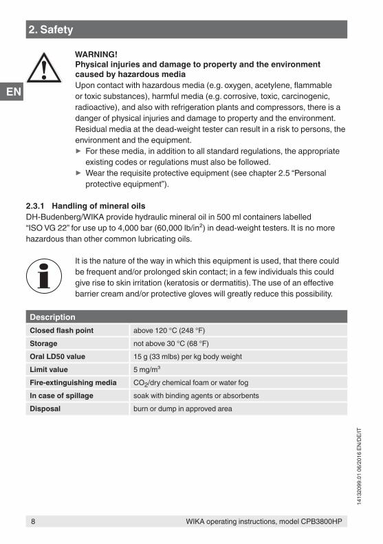
WARNING!Physical injuries and damage to property and the environment caused by hazardous mediaUpon contact with hazardous media (e.g. oxygen, acetylene, flammable or toxic substances), harmful media (e.g. corrosive, toxic, carcinogenic, radioactive), and also with refrigeration plants and compressors, there is a danger of physical injuries and damage to property and the environment.Residual media at the dead-weight tester can result in a risk to persons, the environment and the equipment.
▶ For these media, in addition to all standard regulations, the appropriate existing codes or regulations must also be followed.
▶ Wear the requisite protective equipment (see chapter 2.5 “Personal protective equipment”).
2.3.1 Handling of mineral oilsDH-Budenberg/WIKA provide hydraulic mineral oil in 500 ml containers labelled “ISO VG 22” for use up to 4,000 bar (60,000 lb/in²) in dead-weight testers. It is no more hazardous than other common lubricating oils.
It is the nature of the way in which this equipment is used, that there could be frequent and/or prolonged skin contact; in a few individuals this could give rise to skin irritation (keratosis or dermatitis). The use of an effective barrier cream and/or protective gloves will greatly reduce this possibility.
DescriptionClosed flash point above 120 °C (248 °F)Storage not above 30 °C (68 °F)Oral LD50 value 15 g (33 mlbs) per kg body weightLimit value 5 mg/m³Fire-extinguishing media CO2/dry chemical foam or water fogIn case of spillage soak with binding agents or absorbentsDisposal burn or dump in approved area
2. Safety
9WIKA operating instructions, model CPB3800HP
1413
2099
.01
06/2
016
EN/D
E/IT
EN
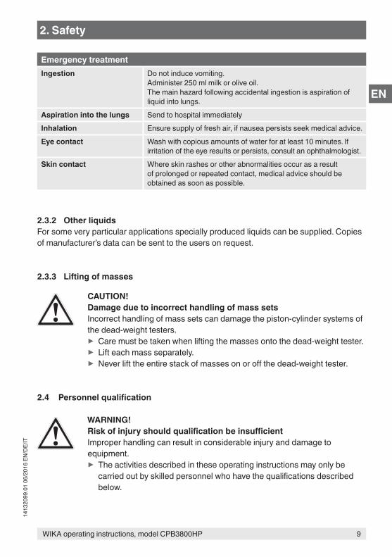
Emergency treatmentIngestion Do not induce vomiting.
Administer 250 ml milk or olive oil.The main hazard following accidental ingestion is aspiration of liquid into lungs.
Aspiration into the lungs Send to hospital immediatelyInhalation Ensure supply of fresh air, if nausea persists seek medical advice.Eye contact Wash with copious amounts of water for at least 10 minutes. If
irritation of the eye results or persists, consult an ophthalmologist.Skin contact Where skin rashes or other abnormalities occur as a result
of prolonged or repeated contact, medical advice should be obtained as soon as possible.
2.3.2 Other liquidsFor some very particular applications specially produced liquids can be supplied. Copies of manufacturer’s data can be sent to the users on request.
2.3.3 Lifting of masses
CAUTION!Damage due to incorrect handling of mass setsIncorrect handling of mass sets can damage the piston-cylinder systems of the dead-weight testers.
▶ Care must be taken when lifting the masses onto the dead-weight tester. ▶ Lift each mass separately. ▶ Never lift the entire stack of masses on or off the dead-weight tester.
2.4 Personnel qualification
WARNING!Risk of injury should qualification be insufficientImproper handling can result in considerable injury and damage to equipment.
▶ The activities described in these operating instructions may only be carried out by skilled personnel who have the qualifications described below.
2. Safety
10 WIKA operating instructions, model CPB3800HP
1413
2099
.01
06/2
016
EN/D
E/IT
EN
Skilled personnelSkilled personnel, authorised by the operator, are understood to be personnel who, based on their technical training, knowledge of measurement and control technology and on their experience and knowledge of country-specific regulations, current standards and directives, are capable of carrying out the work described and independently recognising potential hazards.
Special operating conditions require further appropriate knowledge, e.g. of aggressive media.
DH-Budenberg/WIKA can provide dedicated training courses on the correct use of our products. Please contact your local office for further details.
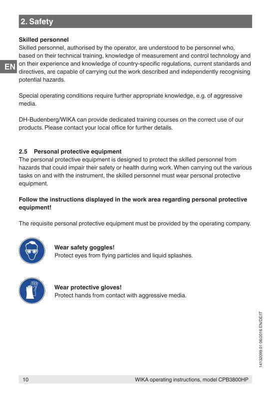
2.5 Personal protective equipmentThe personal protective equipment is designed to protect the skilled personnel from hazards that could impair their safety or health during work. When carrying out the various tasks on and with the instrument, the skilled personnel must wear personal protective equipment.
Follow the instructions displayed in the work area regarding personal protective equipment!
The requisite personal protective equipment must be provided by the operating company.
Wear safety goggles!Protect eyes from flying particles and liquid splashes.
Wear protective gloves!Protect hands from contact with aggressive media.
2. Safety
11WIKA operating instructions, model CPB3800HP
1413
2099
.01
06/2
016
EN/D
E/IT
EN
2.6 Labelling, safety marks
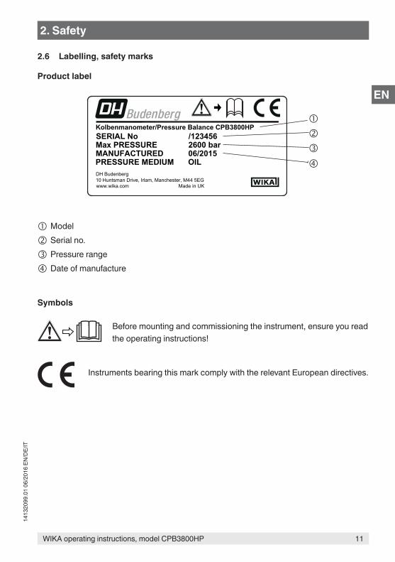
Product label
Model
Serial no.
Pressure range
Date of manufacture
Symbols
Before mounting and commissioning the instrument, ensure you read the operating instructions!
Instruments bearing this mark comply with the relevant European directives.
Kolbenmanometer/Pressure Balance CPB3800HP
OILPRESSURE MEDIUMDH Budenberg10 Huntsman Drive, Irlam, Manchester, M44 5EGwww.wika.com Made in UK
MANUFACTUREDMax PRESSURESERIAL No /123456
2600 bar06/2015
2. Safety
12 WIKA operating instructions, model CPB3800HP
1413
2099
.01
06/2
016
EN/D
E/IT
EN
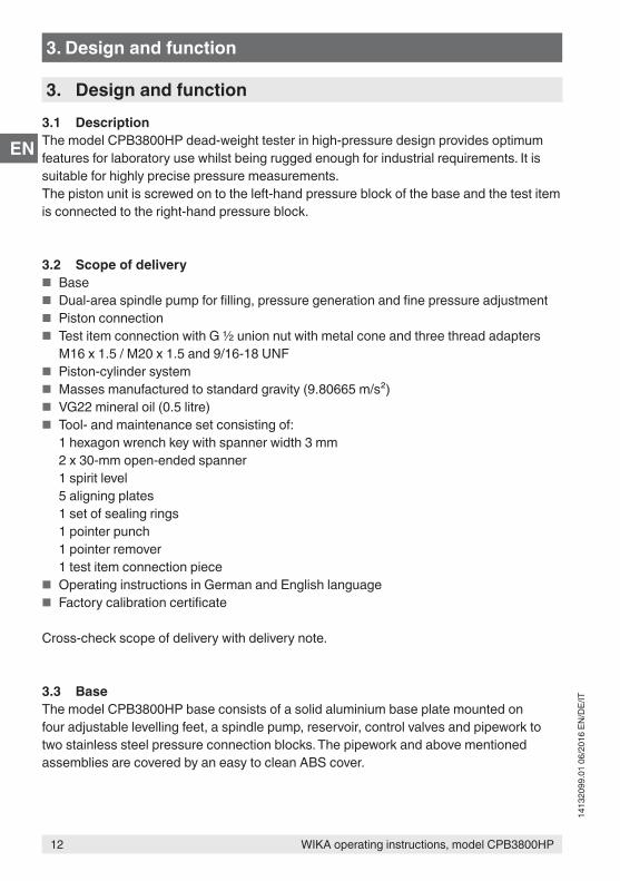
3. Design and function3.1 DescriptionThe model CPB3800HP dead-weight tester in high-pressure design provides optimum features for laboratory use whilst being rugged enough for industrial requirements. It is suitable for highly precise pressure measurements.The piston unit is screwed on to the left-hand pressure block of the base and the test item is connected to the right-hand pressure block.
3.2 Scope of delivery ■ Base ■ Dual-area spindle pump for filling, pressure generation and fine pressure adjustment ■ Piston connection ■ Test item connection with G ½ union nut with metal cone and three thread adapters
M16 x 1.5 / M20 x 1.5 and 9/16-18 UNF ■ Piston-cylinder system ■ Masses manufactured to standard gravity (9.80665 m/s²) ■ VG22 mineral oil (0.5 litre) ■ Tool- and maintenance set consisting of:
1 hexagon wrench key with spanner width 3 mm2 x 30-mm open-ended spanner1 spirit level5 aligning plates1 set of sealing rings1 pointer punch1 pointer remover1 test item connection piece
■ Operating instructions in German and English language ■ Factory calibration certificate
Cross-check scope of delivery with delivery note.
3.3 BaseThe model CPB3800HP base consists of a solid aluminium base plate mounted on four adjustable levelling feet, a spindle pump, reservoir, control valves and pipework to two stainless steel pressure connection blocks. The pipework and above mentioned assemblies are covered by an easy to clean ABS cover.
3. Design and function
13WIKA operating instructions, model CPB3800HP
1413
2099
.01
06/2
016
EN/D
E/IT
EN
E
D GF
C
JH
K
3. Design and function
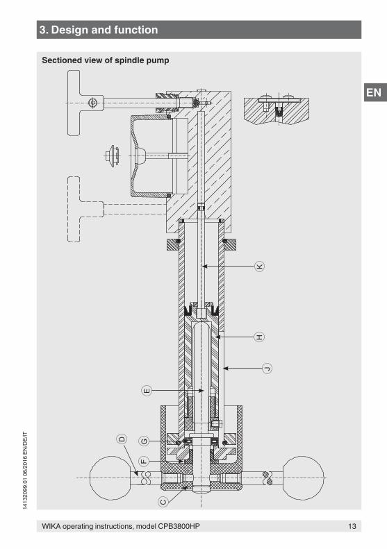
Sectioned view of spindle pump
14 WIKA operating instructions, model CPB3800HP
1413
2099
.01
06/2
016
EN/D
E/IT
EN
3.3.1 Spindle pumpThe spindle pump is bolted to the reservoir/high-pressure cylinder block fastened to the base. A sectioned view of the pump is shown in the following drawing. The rotating handwheel C which is operated by the handles D is attached to a threaded spindle E . The spindle E is supported in a sintered bearing F .As the spindle is rotated, it drives a non-rotating pressure piston H and K forward, the thrust being taken by a needle thrust bearing G . The large diameter of the piston H in the cylinder of the pump J primes the pressure system and provides an initial pressure up to approximately 140 bar (2,000 lb/in²). The small diameter of the piston K in the reservoir/high-pressure cylinder block provides the higher test pressures up to 2,600 bar (40,000 lb/in²).
3.3.2 ReservoirA liquid reservoir is provided on top of the high-pressure cylinder block. The reservoir is provided with a translucent cover to enable the reservoir level to be monitored. A plug in the middle of the reservoir cover allows the reservoir to be filled or topped up (the plug is removed whilst the dead-weight tester is in use). The reservoir contains enough liquid (approximately 150 cm³) to enable normal operation of the dead-weight tester.Displacement volume of low-pressure piston = 60 cm³Displacement volume of high-pressure piston = 10 cm³
3.3.3 Control valvesTwo control valves are provided on top of the reservoir/high-pressure cylinder block. The control valve mechanisms are built into the reservoir/high-pressure cylinder block and they control the flow of liquid through internal drillings in the reservoir/high-pressure cylinder block. The rear valve is referred to as valve A and is used to control the output from the larger diameter piston of the spindle pump. The front valve is referred to as valve B and is used to control the flow of liquid to and from the reservoir.
3.3.4 Connection blocksThe pressure supply pipes from the spindle pump are connected to the base with two pressure connections. The threads of the pressure connections project up through the cover plate of the base. These threaded connections enable piston units to be directly screwed on to them or various sizes of measuring instrument connections to be screwed on to them by means of thread adapters. Oil trays are fitted to the case cover around the threaded connections of the connection blocks to catch any oil drips from the test connection during fitting and removal of measuring instruments.
3. Design and function
15WIKA operating instructions, model CPB3800HP
1413
2099
.01
06/2
016
EN/D
E/IT
EN
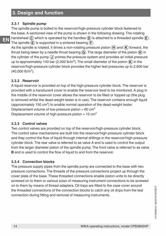
3.4 Piston unitThe piston unit of the model CPB3800HP is a dual-range piston-cylinder system, which covers the measuring range to 2,600 bar (40,000 lb/in²).Masses are loaded directly onto the piston head for low-pressure calibrations. A coloured band indicates when the measuring system is floating. For higher pressure points, a mass carrier is fitted directly to the piston head, and masses are stacked onto the bottom or top of the mass carrier. A machined groove near the top of the mass carrier is used to sight the piston position against the coloured band.
1 Force F2 Effective area A3 High-pressure piston4 Low-pressure piston5 Pressure p
5
1
3
4
2
3. Design and function
16 WIKA operating instructions, model CPB3800HP
1413
2099
.01
06/2
016
EN/D
E/IT
EN
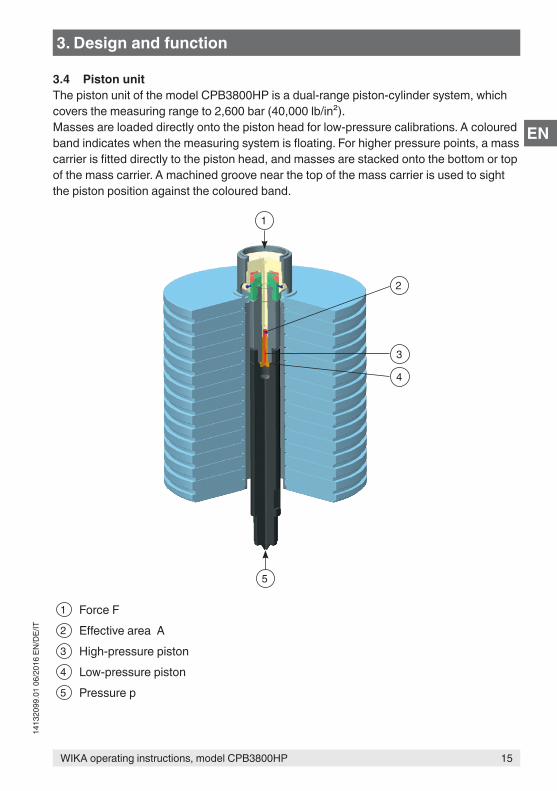
3.5 FunctionsOperation of the dead-weight tester is controlled by the two valves A and B on the top of the reservoir/high-pressure cylinder block. When initially priming the system, the valves A and B are opened to fill the system with oil from the reservoir. Valve B is then closed with valve A left open and the spindle pump operated to provide the lower test pressures.To provide the higher pressures valve A is closed to seal off the test circuit from the low-pressure range of the spindle pump and valve B is opened to allow the liquid in the low-pressure part of the spindle pump to return to the reservoir as the pump is operated. This ensures that the pump can be operated without having to put large forces on the spindle pump handwheel. To release the test pressure the spindle pump is wound out and valve A is opened.
1 Valve A2 Reservoir3 Valve B4 Hand pump
2
1
4
3
3. Design and function
17WIKA operating instructions, model CPB3800HP
1413
2099
.01
06/2
016
EN/D
E/IT
EN
4. Transport, packaging and storage4.1 TransportCheck the model CPB3800HP dead-weight tester in high-pressure design for any damage that may have been caused by transport. Obvious damage must be reported immediately.
CAUTION!Damage through improper transportWith improper transport, a high level of damage to property can occur.
▶ When unloading packed goods upon delivery as well as during internal transport, proceed carefully and observe the symbols on the packaging.
▶ With internal transport, observe the instructions in chapter 4.2 “Packaging and storage”.
If the instrument is transported from a cold into a warm environment, the formation of condensation may result in instrument malfunction. Before putting it back into operation, wait for the instrument temperature and the room temperature to equalise.
4.2 Packaging and storageDo not remove packaging until just before mounting.Keep the packaging as it will provide optimum protection during transport (e.g. change in installation site, sending for repair).
Masses are shipped in cardboard and not in their respective wooden cases, if ordered.Wooden cases are not suitable for use as shipping cases.
Permissible conditions at the place of storage: ■ Storage temperature: -10 ... +50 °C ■ Humidity: 35 ... 85 % relative humidity for instrument base and mass set
35 ... 65 % relative humidity for piston-cylinder system (no condensation)
Avoid exposure to the following factors: ■ Direct sunlight or proximity to hot objects ■ Mechanical vibration, mechanical shock (putting it down hard) ■ Soot, vapour, dust and corrosive gases ■ Hazardous environments, flammable atmospheres ■ Corrosive liquids
4. Transport, packaging and storage
18 WIKA operating instructions, model CPB3800HP
1413
2099
.01
06/2
016
EN/D
E/IT
EN
Store the model CPB3800HP dead-weight tester in its original packaging in a location that fulfils the conditions listed above. If the original packaging is not available, pack and store the instrument as described below:1. Place the instrument, along with shock-absorbent material, in the packaging.2. If stored for a prolonged period of time (more than 30 days), place a bag containing a
desiccant inside the packaging.
4. Transport, packaging and ... / 5. Commissioning, operation
5. Commissioning, operationPersonnel: skilled personnelProtective equipment: safety goggles, protective gloves
Only use original parts (see chapter 10 “Accessories”).
WARNING!Physical injuries and damage to property and the environment caused by hazardous mediaUpon contact with hazardous media (e.g. oxygen, acetylene, flammable or toxic substances), harmful media (e.g. corrosive, toxic, carcinogenic, radioactive), and also with refrigeration plants and compressors, there is a danger of physical injuries and damage to property and the environment.Should a failure occur, aggressive media under high pressure or vacuum may be present at the instrument.
▶ For these media, in addition to all standard regulations, the appropriate existing codes or regulations must also be followed.
▶ Wear the requisite protective equipment (see chapter 2.5 “Personal protective equipment”).
5.1 Unpacking the dead-weight testerAs soon as possible after delivery open the packaging of the dead-weight tester and check that all the items detailed in the packing list (see chapter 3.2 “Scope of delivery”) are included.Unpacking the items, check them for any damage that may have been caused by transport. If any items are missing, please contact DH-Budenberg/WIKA immediately.
19WIKA operating instructions, model CPB3800HP
1413
2099
.01
06/2
016
EN/D
E/IT
EN
5.2 Ambient conditionsWhen siting the dead-weight tester not in a temperature-controlled laboratory look for an area that satisfies the following criteria as much as possible:
■ A constant temperature area free from draughts and sources of heat or cold ■ An area free from noise and vibration or constantly used pathways ■ A clean dry area free from corrosive liquids or vapours
A strong, stable, level table or workbench with the capability of supporting the system with sufficient space to operate is required.
5.3 Installing the base
Fastening the base to the benchThe base is to be mounted on a firm, level table or bench about 0.9 m high. The centre line of the front adjustable feet of the unit should be about 40 mm from the front edge of the bench to allow adequate clearance for the handwheel.
1. Mark the position of the adjustable feet of the unit on the top of the bench.2. Position a level plate at the centre of each of the adjustable feet of the unit and screw
the plate to the bench to ensure that the dead-weight tester is rigid.3. Fit the base on the bench and ensure that the adjustable feet stand on the level plates
and the handwheel shaft projects over the front edge of the bench.4. Screw in the four handwheel spokes into the star handle.5. Using the spirit level provided, level the unit in both the front/rear axis and the side to
side axis by adjusting the four knurled screws at the adjustable feet, by placing the spirit level on top of the piston-cylinder system.
6. Remove the grommet on the left-hand side of the cover to access the piston cylinder support foot. Position the fifth level plate under the base, in line with the piston cylinder support foot, and adjust this until it contacts the level plate. Care must be taken to ensure this operation does not affect the level obtained in operation 5.
5.4 Assembly of the dead-weight tester1. Fit the piston unit to the left-hand connection. Ensure that the mating faces are clean
and the 12 mm diameter O-ring seal correctly located. If using a lb/in² weight set, the piston height adaptor will also have to be fitted. Excess force is not required to achieve an effective seal.
2. Check the level of the base by placing the spirit level on the piston-cylinder system. Level if necessary by using the levelling screws.
3. Fit the appropriate differential nut connection to the test connection, using the coned joints to make the joint and screw a reference gauge (for installation use a known measuring instrument) into position.
5. Commissioning, operation
20 WIKA operating instructions, model CPB3800HP
1413
2099
.01
06/2
016
EN/D
E/IT
EN
When using thread adapters, the thread adapter has to be connected pressure-tight to the test item first.After that the test item with mounted adapter can be inserted into the test connection and can be oriented.
5.4.1 Filling the base with liquid1. Remove plug screw from reservoir by prising plug out. The plug should be left out
during operation.2. Open valves A and B.3. Wind spindle pump handwheel fully clockwise.4. Fill reservoir with appropriate liquid.
CAUTION!Damage to the dead-weight tester caused by wrong liquidsWrong liquids attack the sealings and can lead to leakages and damage the dead-weight tester.
▶ Only use the oil supplied or an approved substitute for hydraulic systems. ▶ Do not use other liquids such as Castor oils, Skydrol, solvents or similar liquids!
5. Wind spindle pump handwheel fully anti-clockwise.6. Top up reservoir if necessary.
5.4.2 Post-assembly test1. Carry out a test calibration of a known test item (see chapter 5.5 “Procedure”) to
ensure that the unit is working correctly.2. Release the pressure and remove the test instrument.
To remove the measuring instrument from the system, use the appropriate size of spanners on the top section of the pressure connection and on the main body of the measuring instrument only. Ensure that the lower part of the pressure connection is not rotated as this may release it from the base.
3. The system is now ready for use.
5. Commissioning, operation
21WIKA operating instructions, model CPB3800HP
1413
2099
.01
06/2
016
EN/D
E/IT
EN
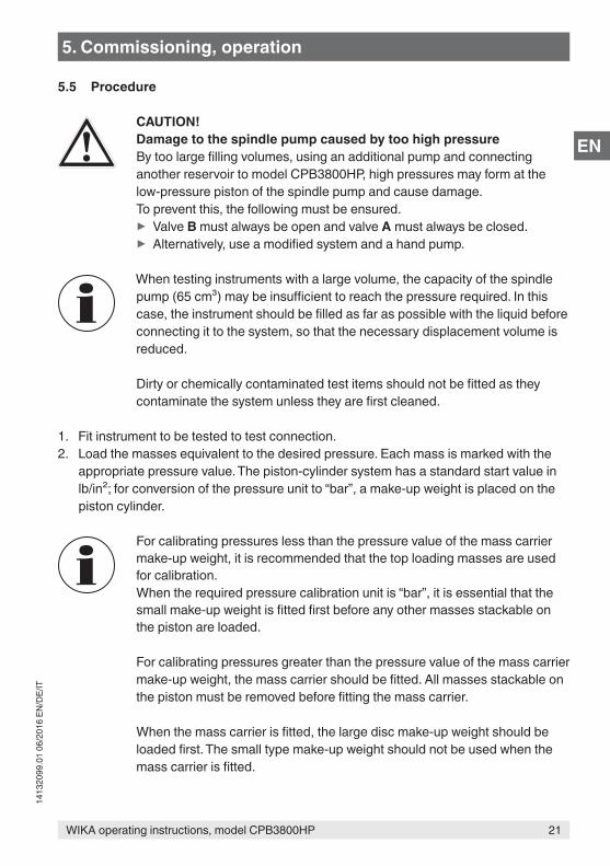
5.5 Procedure
CAUTION!Damage to the spindle pump caused by too high pressureBy too large filling volumes, using an additional pump and connecting another reservoir to model CPB3800HP, high pressures may form at the low-pressure piston of the spindle pump and cause damage.To prevent this, the following must be ensured.
▶ Valve B must always be open and valve A must always be closed. ▶ Alternatively, use a modified system and a hand pump.
When testing instruments with a large volume, the capacity of the spindle pump (65 cm³) may be insufficient to reach the pressure required. In this case, the instrument should be filled as far as possible with the liquid before connecting it to the system, so that the necessary displacement volume is reduced.
Dirty or chemically contaminated test items should not be fitted as they contaminate the system unless they are first cleaned.
1. Fit instrument to be tested to test connection.2. Load the masses equivalent to the desired pressure. Each mass is marked with the
appropriate pressure value. The piston-cylinder system has a standard start value in lb/in²; for conversion of the pressure unit to “bar”, a make-up weight is placed on the piston cylinder.
For calibrating pressures less than the pressure value of the mass carrier make-up weight, it is recommended that the top loading masses are used for calibration.When the required pressure calibration unit is “bar”, it is essential that the small make-up weight is fitted first before any other masses stackable on the piston are loaded.
For calibrating pressures greater than the pressure value of the mass carrier make-up weight, the mass carrier should be fitted. All masses stackable on the piston must be removed before fitting the mass carrier.
When the mass carrier is fitted, the large disc make-up weight should be loaded first. The small type make-up weight should not be used when the mass carrier is fitted.
5. Commissioning, operation
22 WIKA operating instructions, model CPB3800HP
1413
2099
.01
06/2
016
EN/D
E/IT
EN
5.5.1 Pressure loading
For pressures up to 140 bar (2,000 lb/in²)1. Close valve B (valve A remaining open).2. Wind spindle pump handwheel clockwise. This will generate pressure up to
approximately 140 bar (2,000 lb/in²), as handwheel is wound in. When handwheel becomes stiff to rotate this will indicate that the pressure limit for this range has been reached.
For pressures above 140 bar (2,000 lb/in²)1. Ensure that valve B is closed and valve A is open.2. Wind spindle pump handwheel clockwise until the handle becomes stiff to operate.3. Close valve A and open valve B.4. Continue to wind spindle pump handle clockwise. This will generate pressure up to
approximately 2,600 bar (40,000 lb/in²).5. When the piston rises and appears to float, this indicates it is at its nominal pressure.
When only masses stackable on the piston are being utilised, a blue and yellow band indicates the float position. When the mass carrier is being employed, the bottom of the mass carrier will line up with a machined groove in the main body of the piston case, to indicate its desired pressure.
5.5.2 During calibration
CAUTION!Damage due to incorrect handling of massesIncorrect handling of masses can damage the piston-cylinder system of the dead-weight testers or injure the operator.
▶ Care must be taken when rotating the masses. ▶ Only stop the rotary movement by hand. ▶ Only place new masses when they do no longer rotate or the pressure is released completely.
▶ Lift each mass separately. ▶ Never lift the entire stack of masses on or off the dead-weight tester.
When the dead-weight tester is correctly set up and there are no leaks, the piston should “float” for some minutes without it being necessary to touch the spindle pump handwheel. On the initial setting up, however, there may be some air trapped in the main body of the piston-cylinder system. As this leaks past the piston the masses may fall slightly but it will only be for a matter of a few minutes until the air has escaped. If the piston continues to fall, check the connections for leaks.
5. Commissioning, operation
23WIKA operating instructions, model CPB3800HP
1413
2099
.01
06/2
016
EN/D
E/IT
EN
During calibration, the masses should be rotated by hand. It is desirable that the masses should only be rotated when the correct pressure is approximately obtained. Masses should not be brought to rest by fully releasing the pressure and allowing the piston to rotate against its stop under the full load of the masses.
It is essential that the masses spin freely during readings. The piston stops moving when the pressure is too high or too low. At the lowest pressures the masses will not spin for more than a few seconds unless a very thin oil is used, but providing the mass is rotated by hand before taking a reading and is obviously “floating” an accurate reading will be given.
5.5.3 Reference valuesWhen testing gauges on liquid it is occasionally necessary to take into account reference heights of liquid since a height difference of 10 mm corresponds to approximately 1 mbar. The datum levels of the models CPB3800HP piston units are marked with a groove on the outer diameter of the piston unit. It should be noted that when the dead-weight tester is recalibrated by a laboratory other than DH-Budenberg/WIKA, the datum level at which the tests have been carried out may differ from this standard and therefore allowance should be made for any variant should be noted that when the pressure balance is recalibrated by a laboratory other than DH-Budenberg/WIKA, the datum level at which the tests have been carried out may differ from this standard and therefore allowance should be made for any variation..
The drawing shows the head effect that may have to be compensated for when high-accuracy calibration is desired. The following formula will enable the head correction to be calculated.
5. Commissioning, operation
24 WIKA operating instructions, model CPB3800HP
1413
2099
.01
06/2
016
EN/D
E/IT
EN
5.6 Completion1. After the test is finished wind spindle pump handwheel anti-clockwise to lower
pressure.2. Gently open valve A or B to release residual pressure.3. Ensure that both valves A and B are fully open.
The system is now ready for another test and any residual pressure is relieved.
5.7 Temperature measurement of pistonFor many purposes, such as calibrating most types of dial gauges and transducers, accurate knowledge of the piston temperature is not necessary. However, in order to achieve the utmost accuracy from a dead-weight tester it is important to know the piston temperature as close as possible to the piston.
In laboratories where the room temperature is controlled it is most likely that the temperature of the piston will not differ from the ambient temperature by more than 0.5 °C. When working in uncontrolled temperatures, however, one would have to measure the temperature of the piston unit.
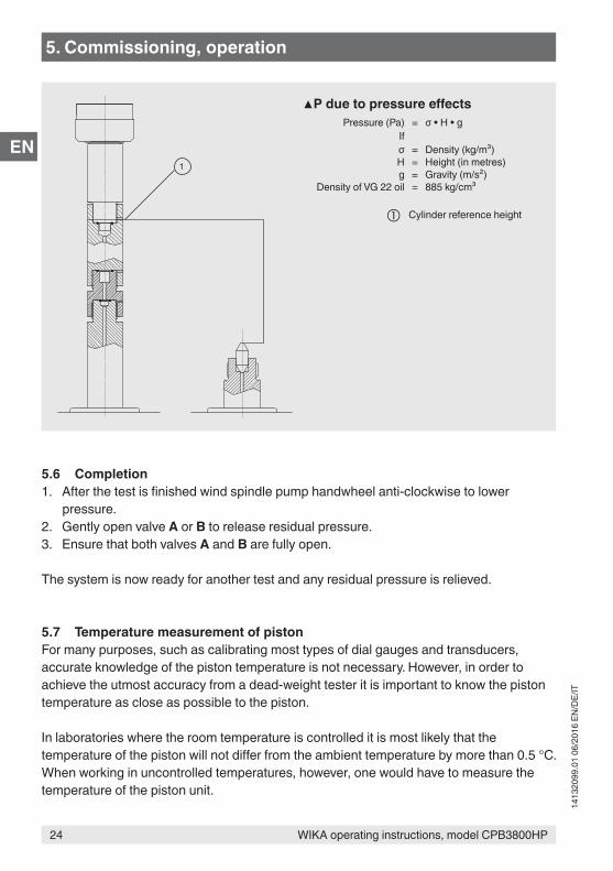
1
▲P due to pressure effectsPressure (Pa) = σ • H • g
Ifσ = Density (kg/m³)H = Height (in metres)g = Gravity (m/s²)
Density of VG 22 oil = 885 kg/cm³
Cylinder reference height
5. Commissioning, operation
25WIKA operating instructions, model CPB3800HP
1413
2099
.01
06/2
016
EN/D
E/IT
EN
A possible way to do this is to use a disc-shaped thermistor-type sensor element taped to the outer surface of the piston unit. The sensor element should be insulated from the ambient temperature by covering the element with a thin strip of polystyrene, or other insulating material, then taping this to the piston unit. Alternatively, the CalibratorUnit model CPU6000 can be used.
A suitable measuring instrument can be supplied. If required, please contact DH-Budenberg/WIKA.
5.8 Cleaning the measuring instrumentsThis cleaning/degreasing process is only suitable for use with pressure measuring instruments with either phosphor, bronze, beryllium, copper, Monel or stainless steel Bourdon tubes in the form of a “C”.
It is not advisable to degrease pressure gauges with steel Bourdon tubes since a very small amount of rust can cause inaccuracies of reading and early failure of the tube.
This method of cleaning is not suitable for use with pressure gauges which are fitted with coiled Bourdon tubes. It is neither suitable for any measuring instruments which are to be used on oxygen, as functioning without oil is not assured. In this case please contact DH-Budenberg/WIKA.
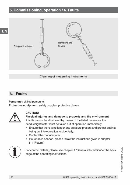
EquipmentThis consists of a syringe and a special needle with the point bent through 90°.
Instructions:1. Fill syringe with solvent (suitable cold degreasing liquid).2. With measuring instrument connection pointing upwards put needle into connection
and carefully insert into the hole leading to the Bourdon tube.3. Inject the solvent. Ideally the pipe should be half full.4. Shake measuring instrument in various attitudes to agitate solvent.5. Suck solvent back into syringe, holding measuring instrument at an angle.6. Check if solvent removed is clean and pure. To be sure that all oil has been removed,
repeat cleaning process until the solvent is as clean as that put in.
5. Commissioning, operation
26 WIKA operating instructions, model CPB3800HP
1413
2099
.01
06/2
016
EN/D
E/IT
EN
Cleaning of measuring instruments
Filling with solventRemoving the solvent
5. Commissioning, operation / 6. Faults
6. Faults
Personnel: skilled personnelProtective equipment: safety goggles, protective gloves
CAUTION!Physical injuries and damage to property and the environmentIf faults cannot be eliminated by means of the listed measures, the dead-weight tester must be taken out of operation immediately.
▶ Ensure that there is no longer any pressure present and protect against being put into operation accidentally.
▶ Contact the manufacturer. ▶ If a return is needed, please follow the instructions given in chapter 8.1 “Return”.
For contact details, please see chapter 1 “General information” or the back page of the operating instructions.
27WIKA operating instructions, model CPB3800HP
1413
2099
.01
06/2
016
EN/D
E/IT
EN
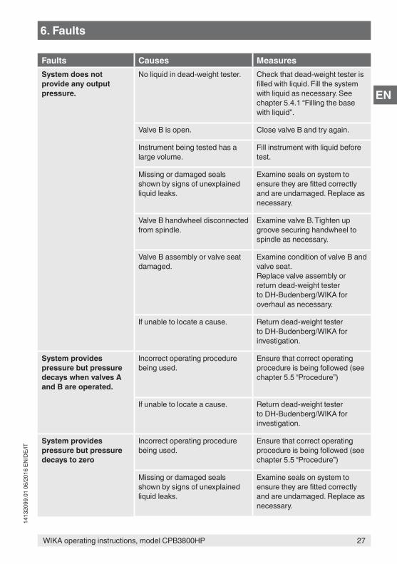
Faults Causes MeasuresSystem does not provide any output pressure.
No liquid in dead-weight tester. Check that dead-weight tester is filled with liquid. Fill the system with liquid as necessary. See chapter 5.4.1 “Filling the base with liquid”.
Valve B is open. Close valve B and try again.
Instrument being tested has a large volume.
Fill instrument with liquid before test.
Missing or damaged seals shown by signs of unexplained liquid leaks.
Examine seals on system to ensure they are fitted correctly and are undamaged. Replace as necessary.
Valve B handwheel disconnected from spindle.
Examine valve B. Tighten up groove securing handwheel to spindle as necessary.
Valve B assembly or valve seat damaged.
Examine condition of valve B and valve seat.Replace valve assembly or return dead-weight tester to DH-Budenberg/WIKA for overhaul as necessary.
If unable to locate a cause. Return dead-weight tester to DH-Budenberg/WIKA for investigation.
System provides pressure but pressure decays when valves A and B are operated.
Incorrect operating procedure being used.
Ensure that correct operating procedure is being followed (see chapter 5.5 “Procedure”)
If unable to locate a cause. Return dead-weight tester to DH-Budenberg/WIKA for investigation.
System provides pressure but pressure decays to zero
Incorrect operating procedure being used.
Ensure that correct operating procedure is being followed (see chapter 5.5 “Procedure”)
Missing or damaged seals shown by signs of unexplained liquid leaks.
Examine seals on system to ensure they are fitted correctly and are undamaged. Replace as necessary.
6. Faults
28 WIKA operating instructions, model CPB3800HP
1413
2099
.01
06/2
016
EN/D
E/IT
EN
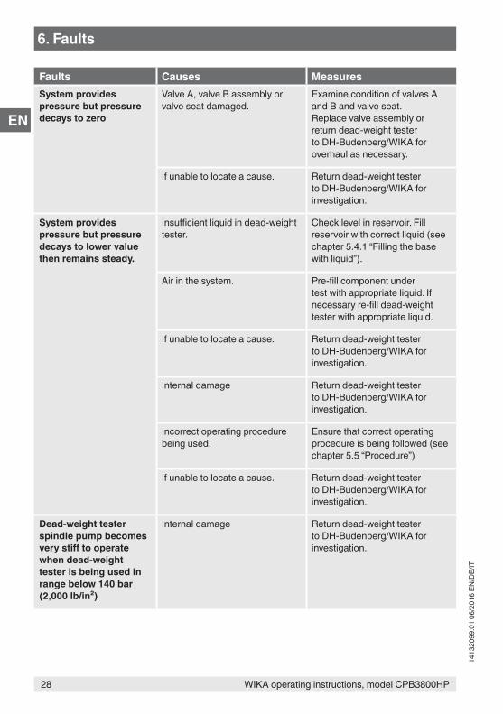
Faults Causes MeasuresSystem provides pressure but pressure decays to zero
Valve A, valve B assembly or valve seat damaged.
Examine condition of valves A and B and valve seat.Replace valve assembly or return dead-weight tester to DH-Budenberg/WIKA for overhaul as necessary.
If unable to locate a cause. Return dead-weight tester to DH-Budenberg/WIKA for investigation.
System provides pressure but pressure decays to lower value then remains steady.
Insufficient liquid in dead-weight tester.
Check level in reservoir. Fill reservoir with correct liquid (see chapter 5.4.1 “Filling the base with liquid”).
Air in the system. Pre-fill component under test with appropriate liquid. If necessary re-fill dead-weight tester with appropriate liquid.
If unable to locate a cause. Return dead-weight tester to DH-Budenberg/WIKA for investigation.
Internal damage Return dead-weight tester to DH-Budenberg/WIKA for investigation.
Incorrect operating procedure being used.
Ensure that correct operating procedure is being followed (see chapter 5.5 “Procedure”)
If unable to locate a cause. Return dead-weight tester to DH-Budenberg/WIKA for investigation.
Dead-weight tester spindle pump becomes very stiff to operate when dead-weight tester is being used in range below 140 bar (2,000 lb/in²)
Internal damage Return dead-weight tester to DH-Budenberg/WIKA for investigation.
6. Faults
29WIKA operating instructions, model CPB3800HP
1413
2099
.01
06/2
016
EN/D
E/IT
EN
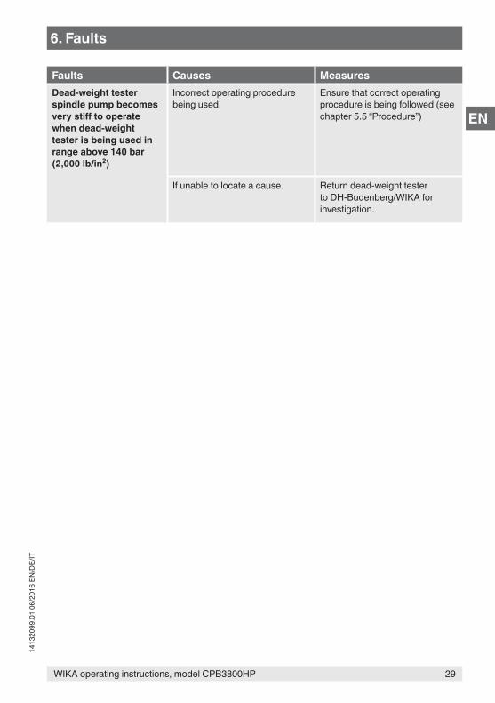
6. Faults
Faults Causes MeasuresDead-weight tester spindle pump becomes very stiff to operate when dead-weight tester is being used in range above 140 bar (2,000 lb/in²)
Incorrect operating procedure being used.
Ensure that correct operating procedure is being followed (see chapter 5.5 “Procedure”)
If unable to locate a cause. Return dead-weight tester to DH-Budenberg/WIKA for investigation.
30 WIKA operating instructions, model CPB3800HP
1413
2099
.01
06/2
016
EN/D
E/IT
EN
7. Maintenance, cleaning and recalibration
Personnel: Skilled personnelProtective equipment: safety goggles, protective gloves
For contact details, please see chapter 1 “General information” or the back page of the operating instructions.
7.1 Periodic maintenanceRepairs must only be carried out by the manufacturer.Only use original parts (see chapter 10 “Accessories”).
Cleaning the units and checking the liquid levels is the only periodic maintenance required. With normal use, no further maintenance should be necessary. If required, the system can be returned to the manufacturer for re-conditioning. Accuracy, overhaul and recertification are also explained in chapter 7.4.1 “Overhaul and recertification of dead-weight testers, maintenance of accuracy”.
Liquids, which attack ABS, should be used with caution. Continuous immersion of the case cover in such liquids will cause damage. Spillages should be wiped off immediately.
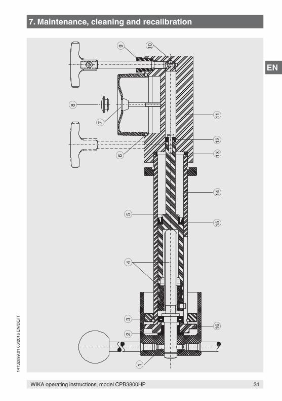
7.2 Corrective maintenance7.2.1 General informationThis section contains details on stripping the unit and replacing the spare parts which are listed (see chapter 10 “Accessories”). The component identification numbers in brackets in each procedure refer to the following drawing.
7. Maintenance, cleaning and recalibration
31WIKA operating instructions, model CPB3800HP
1413
2099
.01
06/2
016
EN/D
E/IT
EN8
7
65
43
2
1
9 10
1112
1314
1516
7. Maintenance, cleaning and recalibration
32 WIKA operating instructions, model CPB3800HP
1413
2099
.01
06/2
016
EN/D
E/IT
EN
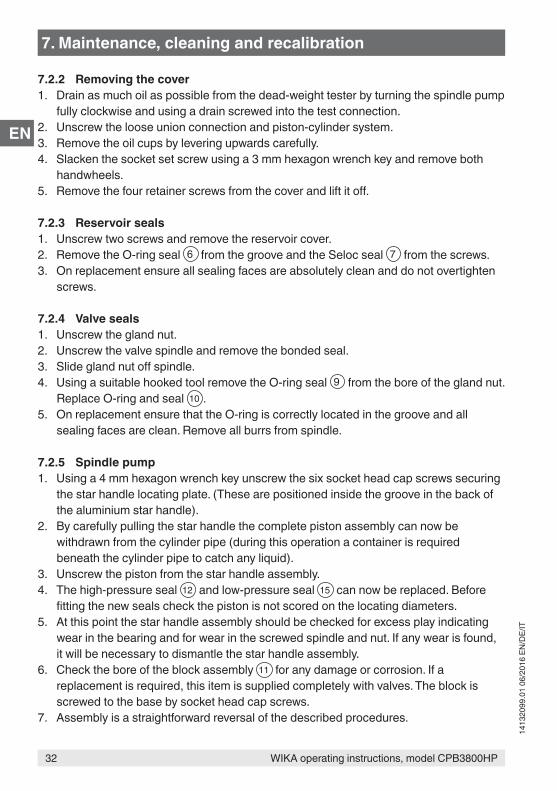
7.2.2 Removing the cover1. Drain as much oil as possible from the dead-weight tester by turning the spindle pump
fully clockwise and using a drain screwed into the test connection.2. Unscrew the loose union connection and piston-cylinder system.3. Remove the oil cups by levering upwards carefully.4. Slacken the socket set screw using a 3 mm hexagon wrench key and remove both
handwheels.5. Remove the four retainer screws from the cover and lift it off.
7.2.3 Reservoir seals1. Unscrew two screws and remove the reservoir cover.2. Remove the O-ring seal 6 from the groove and the Seloc seal 7 from the screws.3. On replacement ensure all sealing faces are absolutely clean and do not overtighten
screws.
7.2.4 Valve seals1. Unscrew the gland nut.2. Unscrew the valve spindle and remove the bonded seal.3. Slide gland nut off spindle.4. Using a suitable hooked tool remove the O-ring seal 9 from the bore of the gland nut.
Replace O-ring and seal 10 .5. On replacement ensure that the O-ring is correctly located in the groove and all
sealing faces are clean. Remove all burrs from spindle.
7.2.5 Spindle pump1. Using a 4 mm hexagon wrench key unscrew the six socket head cap screws securing
the star handle locating plate. (These are positioned inside the groove in the back of the aluminium star handle).
2. By carefully pulling the star handle the complete piston assembly can now be withdrawn from the cylinder pipe (during this operation a container is required beneath the cylinder pipe to catch any liquid).
3. Unscrew the piston from the star handle assembly.4. The high-pressure seal 12 and low-pressure seal 15 can now be replaced. Before
fitting the new seals check the piston is not scored on the locating diameters.5. At this point the star handle assembly should be checked for excess play indicating
wear in the bearing and for wear in the screwed spindle and nut. If any wear is found, it will be necessary to dismantle the star handle assembly.
6. Check the bore of the block assembly 11 for any damage or corrosion. If a replacement is required, this item is supplied completely with valves. The block is screwed to the base by socket head cap screws.
7. Assembly is a straightforward reversal of the described procedures.
7. Maintenance, cleaning and recalibration
33WIKA operating instructions, model CPB3800HP
1413
2099
.01
06/2
016
EN/D
E/IT
EN
On assembly care should be taken to align the piston to prevent bending, or damage to the seals. Excessive force should not be used.
The socket head cap screws are not spaced equally around the locating flanges so check screw hole alignment before inserting the screws.
7.2.6 Star handle assembly1. Unscrew the piston from the spindle. NOTE: left-hand thread.2. Unscrew the spokes from the star handle.3. Knock out the spring bolt 1 , located at the bottom of a threaded hole for the spokes,
of the star handle using a punch with 6 mm diameter. Pull out the star handle.4. The star handle locating plate and thrust bearing can now be removed from the
spindle.5. If the flanged bush 2 is to be renewed, it should be pressed out of the locating plate
and a new one pressed in squarely.6. The thrust bearing 3 must be renewed as a complete component.7. The nut, pin and spindle assembly 4 can only be replaced as a matched pair.
Unscrew the nut from the piston, gripping in a jaw vice and screw in the new nut.8. Assemble the thrust bearing, locating plate and star handle on to the spindle, lubricate
with molybdenum disulphide grease.9. Clamp these items together to eliminate end play and re-assemble spring bolt. If using
new spindle drill through 6.3 mm diameter to fit spring bolt 1 .10. Lubricate the thread with molybdenum disulphide grease and screw into piston nut.
7.2.7 Piston-cylinder systemAs the piston-cylinder system represents a high proportion of the total value of the dead-weight tester, it should always be handled with care and every effort made to keep it clean.
The piston-cylinder system is made to extremely fine limits of accuracy and it is not advisable to dismantle it. If it is necessary to clean it, the piston and cylinder bore must be oiled immediately, in order to protect the high-grade finish.
Should the unit become damaged it should be returned complete for replacement or repair.Parts from different units are not interchangeable as they have to be weighed and evaluated as a whole.
7. Maintenance, cleaning and recalibration
34 WIKA operating instructions, model CPB3800HP
1413
2099
.01
06/2
016
EN/D
E/IT
EN
The serial number of the piston-cylinder system appears in the calibration certificate and is marked on the main body of the unit. This number, as well as the dead-weight tester serial number, should always be quoted in correspondence concerning the piston-cylinder system.
The connections of the piston-cylinder system should always be blanked when they are removed from the dead-weight tester. If the unit is taken off for any reason it should be stored upside-down, resting on the mass carrier.
This covers stripping the unit to enable simple repairs and the fitting of recommended spare parts to be carried out.
7.3 Cleaning
CAUTION!Physical injuries and damage to property and the environmentImproper cleaning may lead to physical injuries and damage to property and the environment. Residual media in the dismounted instrument can result in a risk to personnel, the environment and equipment.
▶ Carry out the cleaning process as described below.
1. Before cleaning, correctly disconnect the instrument from the pressure supply.2. Use the requisite protective equipment.3. Clean the instrument with a moist cloth.
CAUTION!Damage to propertyImproper cleaning may lead to damage to the instrument!
▶ Do not use any aggressive cleaning agents. ▶ Do not use any pointed and hard objects for cleaning.
4. Wash or clean dismounted test items, in order to protect persons and the environment from exposure to residual media.
Cleaning the unit and checking the liquid levelsUse with oilKeep the system clean and free from spilt oil. Wipe out the oil cups under the test connections. Do not use any solvent-containing cleaning agents as they may damage the seals.
7. Maintenance, cleaning and recalibration
35WIKA operating instructions, model CPB3800HP
1413
2099
.01
06/2
016
EN/D
E/IT
EN
Ensure that the reservoir contains sufficient liquid to carry out any calibrations required. If necessary top up the reservoir with the same liquid that is already being used. Do not use any other type of liquid or brand.
If the oil in the dead-weight tester becomes dirty, use the spindle pump to flush clean oil through the instrument with a drain screwed in the test connection. (An angle connection can be used). The spindle pump should be turned fully clockwise before starting.
For information on returning the instrument see chapter 8.1 “Return”.
7.4 Recalibration
DKD/DAkkS certificate - official certificates:We recommend that the instrument is regularly recalibrated by the manufacturer, with time intervals of approx. 5 years. The basic settings will be corrected if necessary.
7.4.1 Overhaul and recertification of dead-weight testers, maintenance of accuracy
The accuracy of a dead-weight tester depends primarily on the effective area of the piston unit and on the masses applied to the piston. The effective area of the piston can be affected by wear of the unit. This is generally caused by contamination of the oil in the dead-weight tester by foreign matter from measuring instruments being calibrated, by water, or by chemicals from measuring instruments, or by corrosion caused by contaminants.
Masses are made of austenitic stainless steel which is entirely stable. They should be periodically cleaned using a non-abrasive method to remove any foreign matter.
7. Maintenance, cleaning and recalibration
36 WIKA operating instructions, model CPB3800HP
1413
2099
.01
06/2
016
EN/D
E/IT
EN
7.4.2 Need for overhaul and recertificationWe recommend that the dead-weight tester be returned to us for overhaul and recertification at any time in the following cases:
■ The piston does not spin freely. ■ The sink rate of the piston is appreciably greater than when new and makes use of the
dead-weight tester difficult. ■ The masses are damaged. ■ The dead-weight tester cannot operate satisfactorily due to wear or damage to pump
or valves which cannot be rectified by the user.
This dead-weight tester can be used for calibration of measuring instruments with an expected accuracy of 1, 0.5 or 0.25 %. Such dead-weight testers need not be sent back frequently for overhaul and recertification and provided they are working well can be trusted for many years. Under these circumstances, an interval of five years might be appropriate between overhauls.
When high accuracy of the dead-weight tester is required, it should be returned for overhaul and recertification more frequently. The actual period will depend on how the dead-weight tester is used. A dead-weight tester kept in a laboratory and carefully used might need to be returned every two to five years. A dead-weight tester carried from site to site and used for calibrating highly precise measuring instruments or transmitters from industrial process plants or for measuring pressures directly in the process might well need to be returned at intervals of less than specified above.
The actual period between overhaul and recertification should be fixed by the user in the light of the above comments taking into account the requirements of any inspection authority, which might be involved.
7.4.3 Identification of massesAll mass sets supplied with a dead-weight tester have been allocated to and are marked with a mass set number. Additionally, if users wish to ensure that only specific masses are used with an individual dead-weight tester or piston-cylinder system, then the serial number of the dead-weight tester, and/or piston unit may also be marked on the main masses. Regrettably due to the small size of certain masses, not all the above information may be marked.
7. Maintenance, cleaning and recalibration
37WIKA operating instructions, model CPB3800HP
1413
2099
.01
06/2
016
EN/D
E/IT
EN
7.4.4 Overhaul and recertificationTo provide the best possible service, the dead-weight tester should be returned as complete unit comprising the base, the piston-cylinder system and all the masses.The base can also be serviced itself. The piston-cylinder system with masses has to be sent back for overhaul. In such instances, certification issued after overhaul can only refer to the piston and cylinder and mass set numbers and not to the base to which they were originally fitted.
Dead-weight tester bases will be stripped, all pipework cleaned, all seals replaced, worn components replaced where desirable, and all reassembled and tested.
The masses will all be checked and brought to within original limits if possible. If one or two masses are missing or repair is not longer economical, they will be replaced. If more than two masses are missing/repair is no longer economical, customer instructions will be sought.
The piston unit will be checked for accuracy and sensitivity. If it is not satisfactory for any reason a quotation will be submitted for a replacement instrument.
A new certificate of accuracy will be issued for each overhauled dead-weight tester. Unless otherwise instructed on order when there has been a slight change in the effective area of the piston the certificate will reflect this; the accuracy will not be affected by more than 0.03 %.
For example the certificate of accuracy of an overhauled dead-weight tester might show that the error does not exceed 0.05 % when the original certificate shows that the error did not exceed 0.02 %.
An UKAS or DKD/DAkkS certificate of calibration can be issued for an overhauled system. Details will be supplied on request.
7. Maintenance, cleaning and recalibration
38 WIKA operating instructions, model CPB3800HP
1413
2099
.01
06/2
016
EN/D
E/IT
EN
8. Return and disposal
Personnel: skilled personnelProtective equipment: safety goggles, protective gloves
WARNING!Physical injuries and damage to property and the environment through residual mediaResidual media at the dead-weight tester can result in a risk to persons, the environment and the equipment.
▶ Wear the requisite protective equipment (see chapter 2.5 “Personal protective equipment”).
▶ Observe the information in the material safety data sheet for the corresponding medium.
▶ Wash or clean the dismounted instrument, in order to protect persons and the environment from exposure to residual media.
8.1 Return
Strictly observe the following when shipping the instrument:All instruments delivered to DH-Budenberg/WIKA must be free from any kind of hazardous substances (acids, bases, solutions, etc.) and must therefore be cleaned before being returned.
WARNING!Physical injuries and damage to property and the environment through residual mediaResidual media at the dead-weight tester can result in a risk to persons, the environment and the equipment.
▶ With hazardous substances, include the material safety data sheet for the corresponding medium.
▶ Clean the instrument, see chapter 7.3 “Cleaning”.
When returning the instrument, use the original packaging or a suitable transport packaging.
To avoid damage:1. Place the piston-cylinder system into the appropriate transport packaging (see
chapter 5.4 “Assembly of the dead-weight tester”).2. Place the instrument, along with shock-absorbent material, in the packaging. Place
shock-absorbent material evenly on all sides of the transport packaging.
8. Return and disposal
39WIKA operating instructions, model CPB3800HP
1413
2099
.01
06/2
016
EN/D
E/IT
EN
3. If possible, place a bag containing a desiccant inside the packaging.4. Label the shipment as carriage of a highly sensitive measuring instrument.
Information on returns can be found under the heading “Service” on our local website.
8.2 DisposalIncorrect disposal can put the environment at risk.Dispose of instrument components and packaging materials in an environmentally compatible way and in accordance with the country-specific waste disposal regulations.
8. Return and disposal
40 WIKA operating instructions, model CPB3800HP
1413
2099
.01
06/2
016
EN/D
E/IT
EN
9. Specifications
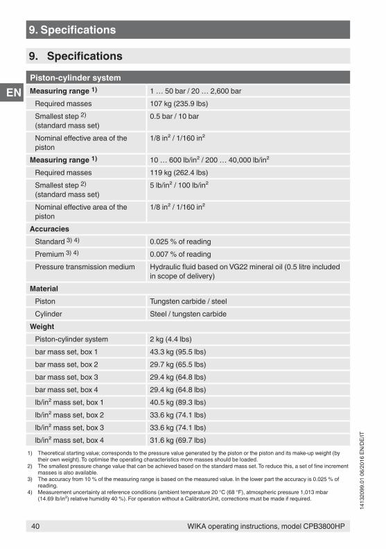
Piston-cylinder systemMeasuring range 1) 1 … 50 bar / 20 … 2,600 bar
Required masses 107 kg (235.9 lbs)Smallest step 2) (standard mass set)
0.5 bar / 10 bar
Nominal effective area of the piston
1/8 in² / 1/160 in²
Measuring range 1) 10 … 600 lb/in² / 200 … 40,000 lb/in²Required masses 119 kg (262.4 lbs)Smallest step 2) (standard mass set)
5 lb/in² / 100 lb/in²
Nominal effective area of the piston
1/8 in² / 1/160 in²
AccuraciesStandard 3) 4) 0.025 % of readingPremium 3) 4) 0.007 % of readingPressure transmission medium Hydraulic fluid based on VG22 mineral oil (0.5 litre included
in scope of delivery)Material
Piston Tungsten carbide / steelCylinder Steel / tungsten carbide
WeightPiston-cylinder system 2 kg (4.4 lbs)bar mass set, box 1 43.3 kg (95.5 lbs)bar mass set, box 2 29.7 kg (65.5 lbs)bar mass set, box 3 29.4 kg (64.8 lbs)bar mass set, box 4 29.4 kg (64.8 lbs)lb/in² mass set, box 1 40.5 kg (89.3 lbs)lb/in² mass set, box 2 33.6 kg (74.1 lbs)lb/in² mass set, box 3 33.6 kg (74.1 lbs)lb/in² mass set, box 4 31.6 kg (69.7 lbs)
1) Theoretical starting value; corresponds to the pressure value generated by the piston or the piston and its make-up weight (by their own weight). To optimise the operating characteristics more masses should be loaded.
2) The smallest pressure change value that can be achieved based on the standard mass set. To reduce this, a set of fine increment masses is also available.
3) The accuracy from 10 % of the measuring range is based on the measured value. In the lower part the accuracy is 0.025 % of reading.
4) Measurement uncertainty at reference conditions (ambient temperature 20 °C (68 °F), atmospheric pressure 1,013 mbar (14.69 lb/in²) relative humidity 40 %). For operation without a CalibratorUnit, corrections must be made if required.
9. Specifications
41WIKA operating instructions, model CPB3800HP
1413
2099
.01
06/2
016
EN/D
E/IT
EN
9. Specifications
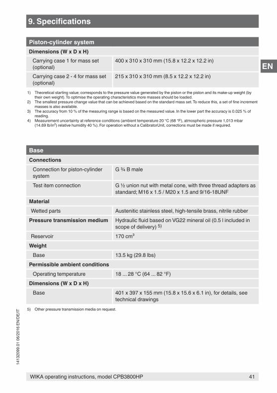
Piston-cylinder systemDimensions (W x D x H)
Carrying case 1 for mass set (optional)
400 x 310 x 310 mm (15.8 x 12.2 x 12.2 in)
Carrying case 2 - 4 for mass set (optional)
215 x 310 x 310 mm (8.5 x 12.2 x 12.2 in)
1) Theoretical starting value; corresponds to the pressure value generated by the piston or the piston and its make-up weight (by their own weight). To optimise the operating characteristics more masses should be loaded.
2) The smallest pressure change value that can be achieved based on the standard mass set. To reduce this, a set of fine increment masses is also available.
3) The accuracy from 10 % of the measuring range is based on the measured value. In the lower part the accuracy is 0.025 % of reading.
4) Measurement uncertainty at reference conditions (ambient temperature 20 °C (68 °F), atmospheric pressure 1,013 mbar (14.69 lb/in²) relative humidity 40 %). For operation without a CalibratorUnit, corrections must be made if required.
BaseConnections
Connection for piston-cylinder system
G ¾ B male
Test item connection G ½ union nut with metal cone, with three thread adapters as standard; M16 x 1.5 / M20 x 1.5 and 9/16-18UNF
MaterialWetted parts Austenitic stainless steel, high-tensile brass, nitrile rubber
Pressure transmission medium Hydraulic fluid based on VG22 mineral oil (0.5 l included in scope of delivery) 5)
Reservoir 170 cm³Weight
Base 13.5 kg (29.8 lbs)Permissible ambient conditions
Operating temperature 18 ... 28 °C (64 ... 82 °F)Dimensions (W x D x H)
Base 401 x 397 x 155 mm (15.8 x 15.6 x 6.1 in), for details, see technical drawings
5) Other pressure transmission media on request.
42 WIKA operating instructions, model CPB3800HP
1413
2099
.01
06/2
016
EN/D
E/IT
EN
9. Specifications
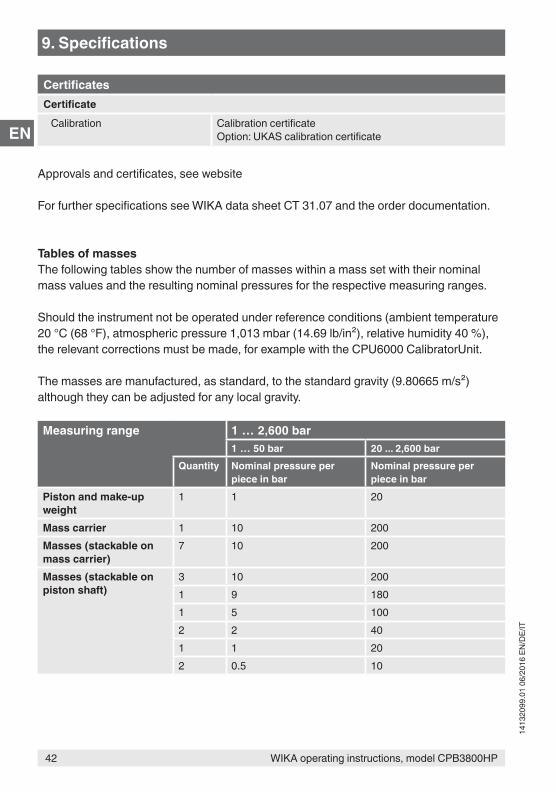
CertificatesCertificate
Calibration Calibration certificateOption: UKAS calibration certificate
Approvals and certificates, see website
For further specifications see WIKA data sheet CT 31.07 and the order documentation.
Tables of massesThe following tables show the number of masses within a mass set with their nominal mass values and the resulting nominal pressures for the respective measuring ranges.
Should the instrument not be operated under reference conditions (ambient temperature 20 °C (68 °F), atmospheric pressure 1,013 mbar (14.69 lb/in²), relative humidity 40 %), the relevant corrections must be made, for example with the CPU6000 CalibratorUnit.
The masses are manufactured, as standard, to the standard gravity (9.80665 m/s²) although they can be adjusted for any local gravity.
Measuring range 1 … 2,600 bar1 … 50 bar 20 ... 2,600 bar
Quantity Nominal pressure per piece in bar
Nominal pressure per piece in bar
Piston and make-up weight
1 1 20
Mass carrier 1 10 200Masses (stackable on mass carrier)
7 10 200
Masses (stackable on piston shaft)
3 10 2001 9 1801 5 1002 2 401 1 202 0.5 10
43WIKA operating instructions, model CPB3800HP
1413
2099
.01
06/2
016
EN/D
E/IT
EN
9. Specifications
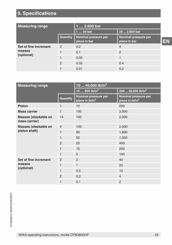
Measuring range 1 … 2,600 bar1 … 50 bar 20 ... 2,600 bar
Quantity Nominal pressure per piece in bar
Nominal pressure per piece in bar
Set of fine increment masses(optional)
2 0.2 41 0.1 21 0.05 12 0.02 0.41 0.01 0.2
Measuring range 10 ... 40,000 lb/in²10 … 600 lb/in² 200 ... 40,000 lb/in²
Quantity Nominal pressure per piece in lb/in²
Nominal pressure per piece in lb/in²
Piston 1 10 200Mass carrier 1 100 2,000Masses (stackable on mass carrier)
14 100 2,000
Masses (stackable on piston shaft)
4 100 2,0001 90 1,8001 50 1,0002 20 4001 10 2001 5 100
Set of fine increment masses(optional)
2 2 401 1 201 0.5 102 0.2 41 0.1 2
44 WIKA operating instructions, model CPB3800HP
1413
2099
.01
06/2
016
EN/D
E/IT
EN
9. Specifications
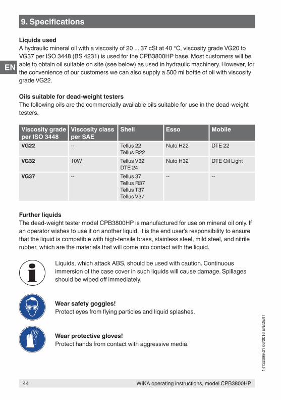
Liquids usedA hydraulic mineral oil with a viscosity of 20 ... 37 cSt at 40 °C, viscosity grade VG20 to VG37 per ISO 3448 (BS 4231) is used for the CPB3800HP base. Most customers will be able to obtain oil suitable on site (see below) as used in hydraulic machinery. However, for the convenience of our customers we can also supply a 500 ml bottle of oil with viscosity grade VG22.
Oils suitable for dead-weight testersThe following oils are the commercially available oils suitable for use in the dead-weight testers.
Viscosity grade per ISO 3448
Viscosity class per SAE
Shell Esso Mobile
VG22 -- Tellus 22Tellus R22
Nuto H22 DTE 22
VG32 10W Tellus V32DTE 24
Nuto H32 DTE Oil Light
VG37 -- Tellus 37Tellus R37Tellus T37Tellus V37
-- --
Further liquidsThe dead-weight tester model CPB3800HP is manufactured for use on mineral oil only. If an operator wishes to use it on another liquid, it is the end user’s responsibility to ensure that the liquid is compatible with high-tensile brass, stainless steel, mild steel, and nitrile rubber, which are the materials that will come into contact with the liquid.
Liquids, which attack ABS, should be used with caution. Continuous immersion of the case cover in such liquids will cause damage. Spillages should be wiped off immediately.
Wear safety goggles!Protect eyes from flying particles and liquid splashes.
Wear protective gloves!Protect hands from contact with aggressive media.
45WIKA operating instructions, model CPB3800HP
1413
2099
.01
06/2
016
EN/D
E/IT
EN
9. Specifications
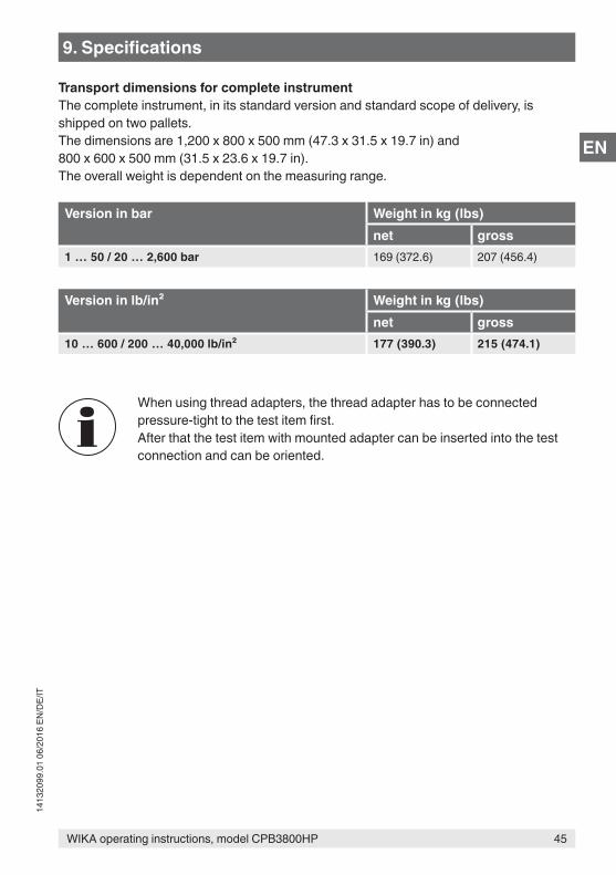
Transport dimensions for complete instrumentThe complete instrument, in its standard version and standard scope of delivery, is shipped on two pallets.The dimensions are 1,200 x 800 x 500 mm (47.3 x 31.5 x 19.7 in) and 800 x 600 x 500 mm (31.5 x 23.6 x 19.7 in).The overall weight is dependent on the measuring range.
Version in bar Weight in kg (lbs)net gross
1 … 50 / 20 … 2,600 bar 169 (372.6) 207 (456.4)
Version in lb/in² Weight in kg (lbs)net gross
10 … 600 / 200 … 40,000 lb/in² 177 (390.3) 215 (474.1)
When using thread adapters, the thread adapter has to be connected pressure-tight to the test item first.After that the test item with mounted adapter can be inserted into the test connection and can be oriented.
46 WIKA operating instructions, model CPB3800HP
1413
2099
.01
06/2
016
EN/D
E/IT
EN
9. Specifications
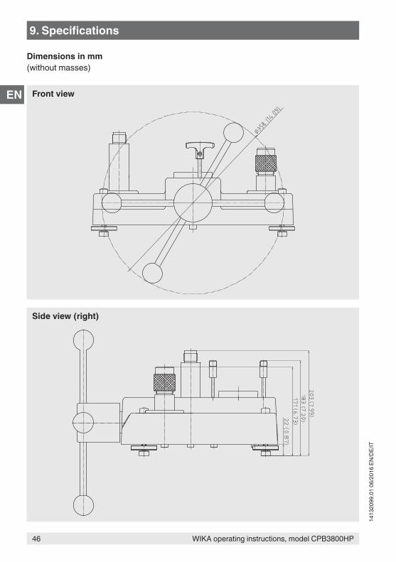
Dimensions in mm(without masses)
Side view (right)
Front view
47WIKA operating instructions, model CPB3800HP
1413
2099
.01
06/2
016
EN/D
E/IT
ENA
140bar +2000lb/in² +
0
0-140bar0-2000lb/in²
R
BA P
AP B
AB P
A B P P
P
B
A
R
CPB3800HP
8
7
1
2
3
4
5
6
9. Specifications
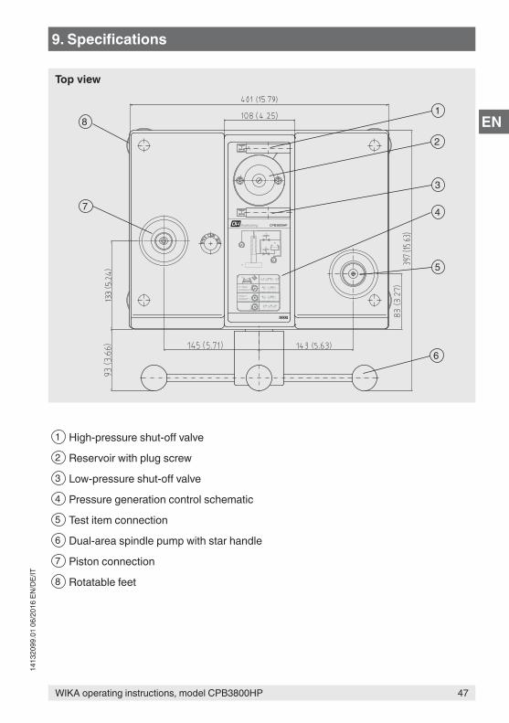
1 High-pressure shut-off valve
2 Reservoir with plug screw
3 Low-pressure shut-off valve
4 Pressure generation control schematic
5 Test item connection
6 Dual-area spindle pump with star handle
7 Piston connection
8 Rotatable feet
Top view
48 WIKA operating instructions, model CPB3800HP
1413
2099
.01
06/2
016
EN/D
E/IT
EN
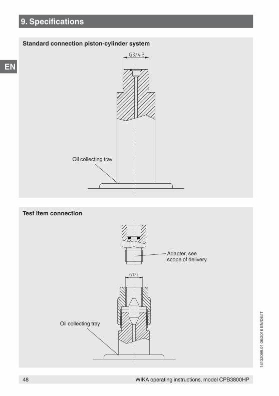
Oil collecting tray
Oil collecting tray
Adapter, see scope of delivery
9. Specifications
Standard connection piston-cylinder system
Test item connection
49WIKA operating instructions, model CPB3800HP
1413
2099
.01
06/2
016
EN/D
E/IT
EN
10. Accessories
Instrument version ■ Various pressure units ■ Systems with increased accuracy to 0.007 %
Calibration ■ UKAS calibration certificate (pressure calibration with a mass set) ■ UKAS calibration certificate (pressure calibration with a piston-cylinder system) ■ UKAS calibration certificate (area and mass calibration) ■ UKAS calibration certificate (mass calibration)
Adapter ■ Adapter for connection column, M16 x 1.5 male thread with sealing cone, mat.:
hardened stainless steel ■ Adapter for connection column, M20 x 1.5 male thread with sealing cone, mat.:
hardened stainless steel ■ Adapter for connection column, 9/16-18 UNF male thread with sealing cone, mat.:
hardened stainless steel ■ Adapter for connection column, G ½ female thread with O-ring, max. 1,600 bar, mat.:
1.4571
Mass sets and fine increment masses ■ Masses manufactured to specified local gravity ■ Set of fine increment masses in bar ■ Set of fine increment masses in lb/in²
Liquids ■ Hydraulic fluid based on VG22 mineral oil in plastic bottle, content 0.5 litre ■ Other pressure transmission media
Storage ■ Storage case for instrument base (and CPB3800HP piston-cylinder system) ■ Four wooden boxes for mass set ■ Storage case for the base, mass set and piston-cylinder system
Tools ■ Sealing and maintenance set for instrument base ■ Tool set consisting of open-ended spanner, replacement seals, pointer remover and
pointer punch
10. Accessories
50 WIKA operating instructions, model CPB3800HP
1413
2099
.01
06/2
016
EN/D
E/IT
EN
WIKA Betriebsanleitung, Typ CPB3800HP
DE
51
1413
2099
.01
06/2
016
EN/D
E/IT
Inhalt
Inhalt1. Allgemeines 532. Sicherheit 54
2.1 Symbolerklärung . . . . . . . . . . . . . . . . . . . . . 542.2 Bestimmungsgemäße Verwendung . . . . . . . . . . . . . . . 542.3 Fehlgebrauch . . . . . . . . . . . . . . . . . . . . . . 55
2.3.1 Umgang mit Mineralölen. . . . . . . . . . . . . . . . . 562.3.2 Andere Flüssigkeiten . . . . . . . . . . . . . . . . . . 572.3.3 Anheben von Massen . . . . . . . . . . . . . . . . . 57
2.4 Personalqualifikation . . . . . . . . . . . . . . . . . . . . 572.5 Persönliche Schutzausrüstung . . . . . . . . . . . . . . . . 582.6 Beschilderung, Sicherheitskennzeichnungen. . . . . . . . . . . . 59
3. Aufbau und Funktion 603.1 Beschreibung . . . . . . . . . . . . . . . . . . . . . . 603.2 Lieferumfang. . . . . . . . . . . . . . . . . . . . . . . 603.3 Basement. . . . . . . . . . . . . . . . . . . . . . . . 60
3.3.1 Spindelpumpe . . . . . . . . . . . . . . . . . . . . 623.3.2 Vorratsbehälter . . . . . . . . . . . . . . . . . . . . 623.3.3 Stellventile . . . . . . . . . . . . . . . . . . . . . 623.3.4 Anschlussblöcke . . . . . . . . . . . . . . . . . . . 62
3.4 Kolbeneinheit . . . . . . . . . . . . . . . . . . . . . . 633.5 Funktionen . . . . . . . . . . . . . . . . . . . . . . . 64
4. Transport, Verpackung und Lagerung 654.1 Transport . . . . . . . . . . . . . . . . . . . . . . . . 654.2 Verpackung und Lagerung . . . . . . . . . . . . . . . . . . 65
5. Inbetriebnahme, Betrieb 665.1 Auspacken der Druckwaage . . . . . . . . . . . . . . . . . 665.2 Umgebungsbedingungen . . . . . . . . . . . . . . . . . . 675.3 Aufstellen des Basements . . . . . . . . . . . . . . . . . . 675.4 Zusammenbau der Druckwaage . . . . . . . . . . . . . . . . 67
5.4.1 Befüllen des Basements mit Flüssigkeit . . . . . . . . . . . 685.4.2 Prüfung nach dem Zusammenbau . . . . . . . . . . . . . 68
5.5 Vorgehensweise . . . . . . . . . . . . . . . . . . . . . 695.5.1 Druckbeaufschlagung . . . . . . . . . . . . . . . . . 705.5.2 Während der Kalibrierung . . . . . . . . . . . . . . . . 705.5.3 Bezugswerte. . . . . . . . . . . . . . . . . . . . . 71
5.6 Abschlussarbeiten . . . . . . . . . . . . . . . . . . . . . 725.7 Kolbentemperaturmessung . . . . . . . . . . . . . . . . . . 725.8 Reinigung der Messgeräte . . . . . . . . . . . . . . . . . . 73
WIKA Betriebsanleitung, Typ CPB3800HP
DE
52
1413
2099
.01
06/2
016
EN/D
E/IT
Inhalt
Konformitätserklärungen finden Sie online unter www.wika.de.
6. Störungen 747. Wartung, Reinigung und Rekalibrierung 78
7.1 Periodische Wartung . . . . . . . . . . . . . . . . . . . . 787.2 Instandhaltung . . . . . . . . . . . . . . . . . . . . . . 78
7.2.1 Allgemein . . . . . . . . . . . . . . . . . . . . . . 787.2.2 Deckel abnehmen . . . . . . . . . . . . . . . . . . . 807.2.3 Behälterdichtungen . . . . . . . . . . . . . . . . . . 807.2.4 Ventildichtungen . . . . . . . . . . . . . . . . . . . 807.2.5 Spindelpumpe . . . . . . . . . . . . . . . . . . . . 807.2.6 Drehkreuz-Baugruppe . . . . . . . . . . . . . . . . . 817.2.7 Kolbenzylindersystem . . . . . . . . . . . . . . . . . 82
7.3 Reinigung. . . . . . . . . . . . . . . . . . . . . . . . 827.4 Rekalibrierung . . . . . . . . . . . . . . . . . . . . . . 83
7.4.1 Überholung und Re-Zertifizierung von Druckwaagen, Wartung der Genauigkeit . . . . . . . . . . . . . . . . . . . . . 84
7.4.2 Notwendigkeit der Überholung und Re-Zertifizierung . . . . . . . 847.4.3 Identifizierung der Massen . . . . . . . . . . . . . . . . 857.4.4 Überholung und Re-Zertifizierung . . . . . . . . . . . . . 85
8. Rücksendung und Entsorgung 868.1 Rücksendung . . . . . . . . . . . . . . . . . . . . . . 868.2 Entsorgung . . . . . . . . . . . . . . . . . . . . . . . 87
9. Technische Daten 8810. Zubehör 97
WIKA Betriebsanleitung, Typ CPB3800HP
DE
53
1413
2099
.01
06/2
016
EN/D
E/IT
1. Allgemeines
■ Die in der Betriebsanleitung beschriebene Druckwaage als Hochdruckausführung Typ CPB3800HP wird nach dem aktuellen Stand der Technik konstruiert und gefertigt. Alle Komponenten unterliegen während der Fertigung strengen Qualitäts- und Umweltkriterien. Unsere Managementsysteme sind nach ISO 9001 und ISO 14001 zertifiziert.
■ Diese Betriebsanleitung gibt wichtige Hinweise zum Umgang mit dem Gerät. Voraussetzung für sicheres Arbeiten ist die Einhaltung aller angegebenen Sicherheitshinweise und Handlungsanweisungen.
■ Die für den Einsatzbereich des Gerätes geltenden örtlichen Unfallverhütungsvorschriften und allgemeinen Sicherheitsbestimmungen einhalten.
■ Die Betriebsanleitung ist Produktbestandteil und muss in unmittelbarer Nähe des Gerätes für das Fachpersonal jederzeit zugänglich aufbewahrt werden. Betriebsanleitung an nachfolgende Benutzer oder Besitzer des Gerätes weitergeben.
■ Das Fachpersonal muss die Betriebsanleitung vor Beginn aller Arbeiten sorgfältig durchgelesen und verstanden haben.
■ Es gelten die allgemeinen Geschäftsbedingungen in den Verkaufsunterlagen.
■ Technische Änderungen vorbehalten.
■ Werkskalibrierungen / DKD/DAkkS-Kalibrierungen erfolgen nach internationalen Normen.
■ Weitere Informationen:DH-BudenbergA division of WIKA Instruments Ltd.- Internet-Adresse: www.wika.de / www.wika.com- zugehöriges Datenblatt: CT 31.07- Anwendungsberater: Tel.: +44 844 4060086
Fax: +44 844 [email protected]
1. Allgemeines
WIKA Betriebsanleitung, Typ CPB3800HP
DE
54
1413
2099
.01
06/2
016
EN/D
E/IT
WIKA Alexander Wiegand SE & Co. KG- Internet-Adresse: www.wika.de / www.wika.com- zugehöriges Datenblatt: CT 31.07- Anwendungsberater: Tel.: +49 9372/132-0
Fax: +49 9372/[email protected]
1. Allgemeines / 2. Sicherheit
2. Sicherheit
2.1 Symbolerklärung
WARNUNG!... weist auf eine möglicherweise gefährliche Situation hin, die zum Tod oder zu schweren Verletzungen führen kann, wenn sie nicht gemieden wird.
VORSICHT!... weist auf eine möglicherweise gefährliche Situation hin, die zu geringfügigen oder leichten Verletzungen bzw. Sach- und Umweltschäden führen kann, wenn sie nicht gemieden wird.
Information... hebt nützliche Tipps und Empfehlungen sowie Informationen für einen effizienten und störungsfreien Betrieb hervor.
2.2 Bestimmungsgemäße VerwendungKolbenmanometer (Druckwaagen) sind die genauesten am Markt verfügbaren Geräte zur Kalibrierung von elektronischen oder mechanischen Druckmessgeräten. Durch die Messung des Druckes als Quotient aus Kraft und Fläche (p = F/A) sind Kolbenmanometer (Druckwaagen) als Primärnormale zugelassen.
Das Herzstück der Druckwaage Typ CPB3800HP bildet dementsprechend ein sehr präzise gefertigtes Kolbenzylindersystem, das zur Erzeugung der einzelnen Prüfpunkte mit Massensätzen belastet wird. Der Massensatz ist proportional zu dem angestreb-ten Druck und wird durch abgestufte Massen erreicht. Ein maximaler Druck von 2.600 bar (40.000 lb/in²) darf nicht überschritten werden.
WIKA Betriebsanleitung, Typ CPB3800HP
DE
55
1413
2099
.01
06/2
016
EN/D
E/IT
2. Sicherheit
Die Einstellung des Druckes erfolgt über eine integrierte, sehr fein regulierbare Zweibereichs-Präzisionspindelpumpe. Sobald sich dann das Messsystem im Schwebe-zustand befindet, herrscht ein Kräftegleichgewicht zwischen Druck und Massenauflagen. Der Prüfling kann somit kalibriert oder justiert werden.
Aufgrund der autarken Arbeitsweise (integrierte Druckerzeugung sowie dem rein mechanischen Messprinzip), ist der Typ CPB3800HP ideal für den Einsatz vor Ort, in der Wartung und im Service geeignet.
Dieses Gerät ist nicht für den Einsatz in explosionsgefährdeten Bereichen zugelassen!
Das Gerät ist ausschließlich für den hier beschriebenen bestimmungsgemäßen Verwen-dungszweck konzipiert und konstruiert und darf nur dementsprechend verwendet werden.
Die technischen Spezifikationen in dieser Betriebsanleitung sind einzuhalten. Eine unsachgemäße Handhabung oder ein Betreiben des Gerätes außerhalb der technischen Spezifikationen macht die sofortige Stilllegung und Überprüfung durch einen autorisierten WIKA-Servicemitarbeiter erforderlich.
Mechanische Präzisionsmessgeräte mit erforderlicher Sorgfalt behandeln (vor Nässe, Stößen, starken Magnetfeldern, statischer Elektrizität und extremen Temperaturen schützen, keine Gegenstände in das Gerät bzw. Öffnungen einführen). Stecker und Buchsen vor Verschmutzung schützen.
Ansprüche jeglicher Art aufgrund von nicht bestimmungsgemäßer Verwendung sind ausgeschlossen.
2.3 Fehlgebrauch
WARNUNG!Verletzungen durch FehlgebrauchFehlgebrauch des Gerätes kann zu gefährlichen Situationen und Verletzungen führen.
▶ Eigenmächtige Umbauten am Gerät unterlassen. ▶ Gerät nicht in explosionsgefährdeten Bereichen einsetzen. ▶ Gerät nicht für abrassive und viskose Messstoffe verwenden.
Jede über die bestimmungsgemäße Verwendung hinausgehende oder andersartige Benutzung gilt als Fehlgebrauch.
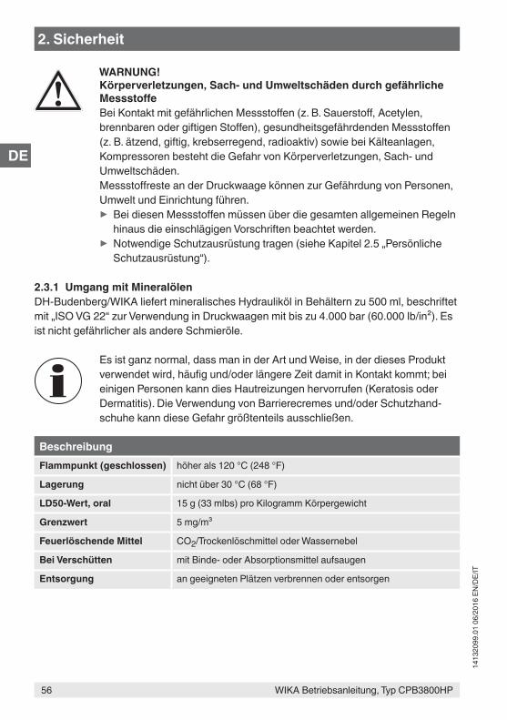
WIKA Betriebsanleitung, Typ CPB3800HP
DE
56
1413
2099
.01
06/2
016
EN/D
E/IT
WARNUNG!Körperverletzungen, Sach- und Umweltschäden durch gefährliche MessstoffeBei Kontakt mit gefährlichen Messstoffen (z. B. Sauerstoff, Acetylen, brennbaren oder giftigen Stoffen), gesundheitsgefährdenden Messstoffen (z. B. ätzend, giftig, krebserregend, radioaktiv) sowie bei Kälteanlagen, Kompressoren besteht die Gefahr von Körperverletzungen, Sach- und Umweltschäden.Messstoffreste an der Druckwaage können zur Gefährdung von Personen, Umwelt und Einrichtung führen.
▶ Bei diesen Messstoffen müssen über die gesamten allgemeinen Regeln hinaus die einschlägigen Vorschriften beachtet werden.
▶ Notwendige Schutzausrüstung tragen (siehe Kapitel 2.5 „Persönliche Schutzausrüstung“).
2.3.1 Umgang mit MineralölenDH-Budenberg/WIKA liefert mineralisches Hydrauliköl in Behältern zu 500 ml, beschriftet mit „ISO VG 22“ zur Verwendung in Druckwaagen mit bis zu 4.000 bar (60.000 lb/in²). Es ist nicht gefährlicher als andere Schmieröle.
Es ist ganz normal, dass man in der Art und Weise, in der dieses Produkt verwendet wird, häufig und/oder längere Zeit damit in Kontakt kommt; bei einigen Personen kann dies Hautreizungen hervorrufen (Keratosis oder Dermatitis). Die Verwendung von Barrierecremes und/oder Schutzhand-schuhe kann diese Gefahr größtenteils ausschließen.
BeschreibungFlammpunkt (geschlossen) höher als 120 °C (248 °F)
Lagerung nicht über 30 °C (68 °F)
LD50-Wert, oral 15 g (33 mlbs) pro Kilogramm Körpergewicht
Grenzwert 5 mg/m³
Feuerlöschende Mittel CO2/Trockenlöschmittel oder Wassernebel
Bei Verschütten mit Binde- oder Absorptionsmittel aufsaugen
Entsorgung an geeigneten Plätzen verbrennen oder entsorgen
2. Sicherheit
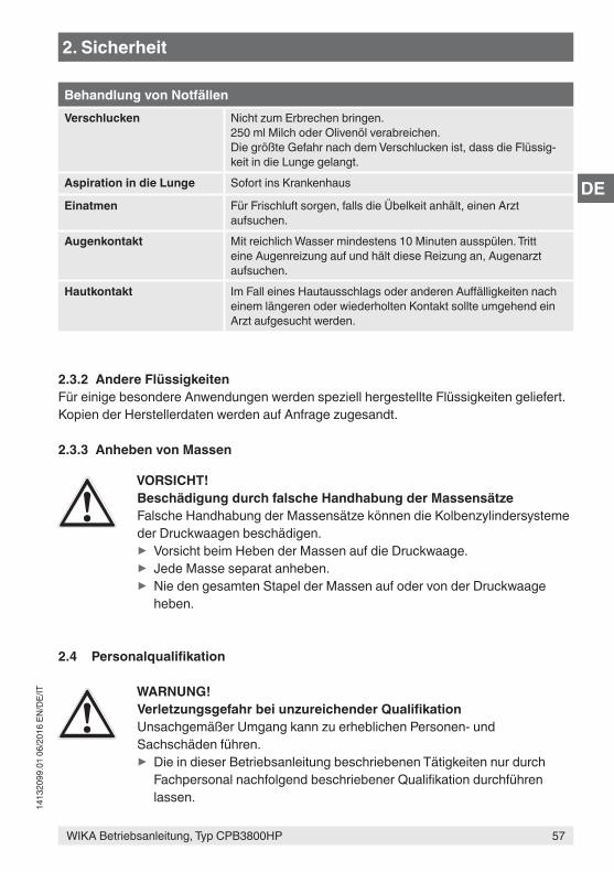
WIKA Betriebsanleitung, Typ CPB3800HP
DE
57
1413
2099
.01
06/2
016
EN/D
E/IT
Behandlung von NotfällenVerschlucken Nicht zum Erbrechen bringen.
250 ml Milch oder Olivenöl verabreichen.Die größte Gefahr nach dem Verschlucken ist, dass die Flüssig-keit in die Lunge gelangt.
Aspiration in die Lunge Sofort ins Krankenhaus
Einatmen Für Frischluft sorgen, falls die Übelkeit anhält, einen Arzt aufsuchen.
Augenkontakt Mit reichlich Wasser mindestens 10 Minuten ausspülen. Tritt eine Augenreizung auf und hält diese Reizung an, Augenarzt aufsuchen.
Hautkontakt Im Fall eines Hautausschlags oder anderen Auffälligkeiten nach einem längeren oder wiederholten Kontakt sollte umgehend ein Arzt aufgesucht werden.
2.3.2 Andere FlüssigkeitenFür einige besondere Anwendungen werden speziell hergestellte Flüssigkeiten geliefert. Kopien der Herstellerdaten werden auf Anfrage zugesandt.
2.3.3 Anheben von Massen
VORSICHT!Beschädigung durch falsche Handhabung der MassensätzeFalsche Handhabung der Massensätze können die Kolbenzylindersysteme der Druckwaagen beschädigen.
▶ Vorsicht beim Heben der Massen auf die Druckwaage. ▶ Jede Masse separat anheben. ▶ Nie den gesamten Stapel der Massen auf oder von der Druckwaage heben.
2.4 Personalqualifikation
WARNUNG!Verletzungsgefahr bei unzureichender QualifikationUnsachgemäßer Umgang kann zu erheblichen Personen- und Sachschäden führen.
▶ Die in dieser Betriebsanleitung beschriebenen Tätigkeiten nur durch Fachpersonal nachfolgend beschriebener Qualifikation durchführen lassen.
2. Sicherheit
WIKA Betriebsanleitung, Typ CPB3800HP
DE
58
1413
2099
.01
06/2
016
EN/D
E/IT
FachpersonalDas vom Betreiber autorisierte Fachpersonal ist aufgrund seiner fachlichen Ausbildung, seiner Kenntnisse der Mess- und Regelungstechnik und seiner Erfahrungen sowie Kenntnis der landesspezifischen Vorschriften, geltenden Normen und Richtlinien in der Lage, die beschriebenen Arbeiten auszuführen und mögliche Gefahren selbstständig zu erkennen.
Spezielle Einsatzbedingungen verlangen weiteres entsprechendes Wissen, z. B. über aggressive Medien.
DH-Budenberg/WIKA bieten entsprechende Schulungen für den korrekten Einsatz unserer Produkte an. Für weitere Details bitte unser Büro vor Ort kontatktieren.
2.5 Persönliche SchutzausrüstungDie persönliche Schutzausrüstung dient dazu, das Fachpersonal gegen Gefahren zu schützen, die dessen Sicherheit oder Gesundheit bei der Arbeit beeinträchtigen könnten. Beim Ausführen der verschiedenen Arbeiten an und mit dem Gerät muss das Fachpersonal persönliche Schutzausrüstung tragen.
Im Arbeitsbereich angebrachte Hinweise zur persönlichen Schutzausrüstung befolgen!
Die erforderliche persönliche Schutzausrüstung muss vom Betreiber zur Verfügung gestellt werden.
Schutzbrille tragen!Schutz der Augen vor umherfliegenden Teilen und Flüssigkeitsspritzern.
Schutzhandschuhe tragen!Schutz der Hände vor Berührung mit aggressiven Medien.
2. Sicherheit
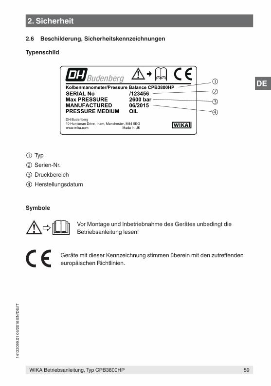
WIKA Betriebsanleitung, Typ CPB3800HP
DE
59
1413
2099
.01
06/2
016
EN/D
E/IT
2.6 Beschilderung, Sicherheitskennzeichnungen
Typenschild
Typ
Serien-Nr.
Druckbereich
Herstellungsdatum
Symbole
Vor Montage und Inbetriebnahme des Gerätes unbedingt die Betriebsanleitung lesen!
Geräte mit dieser Kennzeichnung stimmen überein mit den zutreffenden europäischen Richtlinien.
Kolbenmanometer/Pressure Balance CPB3800HP
OILPRESSURE MEDIUMDH Budenberg10 Huntsman Drive, Irlam, Manchester, M44 5EGwww.wika.com Made in UK
MANUFACTUREDMax PRESSURESERIAL No /123456
2600 bar06/2015
2. Sicherheit
WIKA Betriebsanleitung, Typ CPB3800HP
DE
60
1413
2099
.01
06/2
016
EN/D
E/IT
3. Aufbau und Funktion3.1 BeschreibungDie Druckwaage als Hochdruckausführung Typ CPB3800HP bietet die optimalen Eigen-schaften für eine Verwendung im Labor, sowie auch die notwendige Robustheit für indus-trielle Anforderungen. Es eignet sich für hochpräzise Druckmessungen.Die Kolbeneinheit wird an den linken Druckblock des Basements geschraubt und der Prüfling wird mit dem rechten Druckblock verbunden.
3.2 Lieferumfang ■ Basement ■ Zweibereichsspindelpumpe zum Füllen, Druckaufbau und Druckfeineinstellung ■ Kolbenaufnahme ■ Prüflingsanschluss mit G ½ Überwurfmutter mit Metallkonus und drei
Gewindeadaptern M16 x 1,5 / M20 x 1,5 und 9/16-18 UNF ■ Kolbenzylindersystem ■ Massen gefertigt auf Norm-Fallbeschleunigung (9,80665 m/s²) ■ Mineralöl VG22 (0,5 Liter) ■ Werkzeug- und Wartungsset bestehend aus:
1 Sechskantschlüssel mit Schlüsselweite 3 mm2 x 30-mm-Gabelschlüssel1 Wasserwaage5 Ausrichtungsplatten1 Satz Dichtungsringe1 Zeigeraufschlagstempel1 Zeigerabhebevorrichtung1 Prüflingsanschlussstück
■ Betriebsanleitung in deutscher und englischer Sprache ■ Werkskalibrierschein
Lieferumfang mit dem Lieferschein abgleichen.
3.3 BasementDas Basement der CPB3800HP besteht aus einer massiven Grundplatte aus Aluminium, die aus vier höhenverstellbaren Füßen, einer Spindelpumpe, einem Vorratsbehälter, Stell-ventilen und Verrohrung zu zwei CrNi-Stahl-Druckanschlussblöcken besteht. Die Verroh-rung und die oben genannten Baugruppen sind mit einer ABS-Abdeckung versehen, die leicht zu reinigen ist.
3. Aufbau und Funktion

WIKA Betriebsanleitung, Typ CPB3800HP
DE
61
1413
2099
.01
06/2
016
EN/D
E/IT
E
D GF
C
JH
K
3. Aufbau und Funktion
Schnitt durch die Spindelpumpe
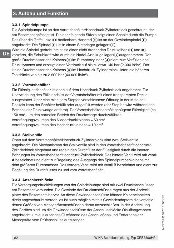
WIKA Betriebsanleitung, Typ CPB3800HP
DE
62
1413
2099
.01
06/2
016
EN/D
E/IT
3. Aufbau und Funktion
3.3.1 SpindelpumpeDie Spindelpumpe ist an den Vorratsbehälter/Hochdruck-Zylinderblock geschraubt, der am Basement befestigt ist. Die nachfolgende Skizze zeigt einen Schnitt durch die Pumpe. Das über die Griffstücke D bedienbare Handrad C ist an der Gewindespindel E angebracht. Die Spindel E ist in einem Sinterlager gelagert F .Wird die Spindel gedreht, treibt sie einen nicht drehenden Druckkolben H und K vorwärts, die Schubkraft wird durch ein Nadel-Axialkugellager G aufgenommen. Der große Durchmesser des Kolbens H im Pumpenzylinder J dient zum Vorfüllen des Drucksystems und erzeugt einen Vordruck auf bis zu etwa 140 bar (2.000 lb/in²). Der kleine Durchmesser des Kolbens K im Hochdruck-Zylinderblock liefert die höheren Testdrücke von bis zu 2.600 bar (40.000 lb/in²).
3.3.2 VorratsbehälterEin Flüssigkeitsbehälter ist oben auf dem Hochdruck-Zylinderblock angebracht. Zur Überwachung des Füllstands ist der Vorratsbehälter mit einen transparenten Deckel ausgestattet. Über eine mit einem Stopfen verschlossene Öffnung in der Mitte des Deckels kann der Behälter befüllt oder aufgefüllt werden (der Stopfen wird während des Betriebs der Druckwaage entfernt). Der Vorratsbehälter enthält genügend Flüssigkeit (ca. 150 cm³) um den normalen Betrieb der Druckwaage durchzuführen.Verdrängungsvolumen des Niederdruckkolbens = 60 cm³Verdrängungsvolumen des Hochdruckkolbens = 10 cm³
3.3.3 StellventileOben auf dem Vorratsbehälter/Hochdruck-Zylinderblock sind zwei Stellventile angebracht. Die Mechanismen der Stellventile sind in den Vorratsbehälter/Hochdruck-Zylinderblock eingebaut und regeln den Durchfluss der Flüssigkeit durch die inneren Bohrungen im Vorratsbehälter/Hochdruck-Zylinderblock. Das hintere Ventil wird mit Ventil A bezeichnet und dient zur Regelung des Ausgangs des Spindelpumpenkolbens mit dem größeren Durchmesser. Das vordere Ventil wird mit Ventil B bezeichnet und dient zur Regelung des Durchflusses zu und vom Vorratsbehälter.
3.3.4 AnschlussblöckeDie Versorgungsdruckleitungen von der Spindelpumpe sind mit zwei Druckanschlüssen am Basement verbunden. Die Gewinde der Druckanschlüsse ragen aus der Abdeck-platte des Basements hervor. An diese Gewindeanschlüsse können Kolbeneinheiten direkt angeschraubt werden; es ist auch möglich mittels Gewindeadaptern die verschie-denen Größen von Messgeräteanschlüssen daran anzuschließen. In der Abdeckung des Gerätes sind um die Gewindeanschlüsse der Anschlussblöcke Ölauffangwannen angebracht, um auslaufendes Öl während des Anschließens und Entfernens der Messgeräte vom Prüfanschluss aufzufangen.
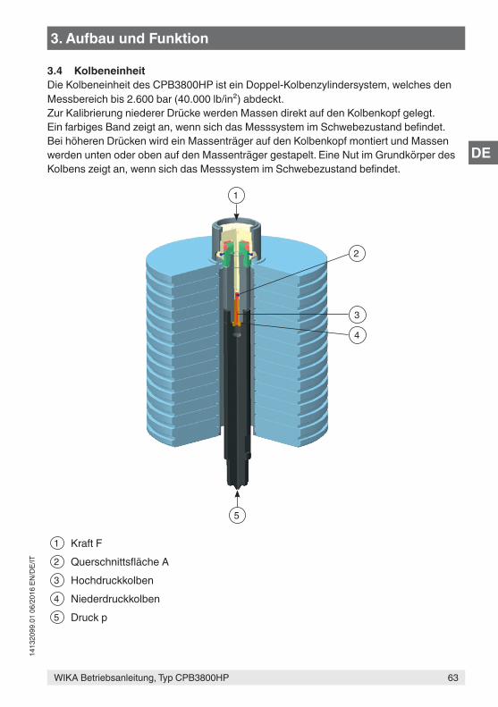
WIKA Betriebsanleitung, Typ CPB3800HP
DE
63
1413
2099
.01
06/2
016
EN/D
E/IT
3.4 KolbeneinheitDie Kolbeneinheit des CPB3800HP ist ein Doppel-Kolbenzylindersystem, welches den Messbereich bis 2.600 bar (40.000 lb/in²) abdeckt.Zur Kalibrierung niederer Drücke werden Massen direkt auf den Kolbenkopf gelegt. Ein farbiges Band zeigt an, wenn sich das Messsystem im Schwebezustand befindet. Bei höheren Drücken wird ein Massenträger auf den Kolbenkopf montiert und Massen werden unten oder oben auf den Massenträger gestapelt. Eine Nut im Grundkörper des Kolbens zeigt an, wenn sich das Messsystem im Schwebezustand befindet.
1 Kraft F2 Querschnittsfläche A3 Hochdruckkolben4 Niederdruckkolben5 Druck p
5
1
3
4
2
3. Aufbau und Funktion
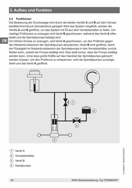
WIKA Betriebsanleitung, Typ CPB3800HP
DE
64
1413
2099
.01
06/2
016
EN/D
E/IT
3. Aufbau und Funktion
3.5 FunktionenDie Bedienung der Druckwaage wird durch die beiden Ventile A und B auf dem Vorrats-behälter/Hochdruck-Zylinderblock geregelt. Wird das System vorgefüllt, werden die Ventile A und B geöffnet, um das System mit Öl aus dem Vorratsbehälter zu füllen. Um niedrige Prüfdrücke zu erzeugen wird Ventil B geschlossen, während das Ventil A offen bleibt und die Spindelpumpe betätigt wird.Um höhere Drücke zu erzeugen, wird Ventil A geschlossen, um den Prüfkreis gegen den Niederdruckbereich der Spindelpumpe abzudichten; Ventil B wird geöffnet, damit die Flüssigkeit im Niederdruckbereich der Spindelpumpe in den Vorratsbehälter zurück-fließen kann, sobald die Pumpe betätigt wird. Dies stellt sicher, dass die Pumpe betätigt werden kann, ohne dass große Kräfte auf das Handrad der Spindelpumpe gebracht werden müssen. Um den Prüfdruck zu entspannen, wird die Spindelpumpe zurückge-dreht und das Ventil A geöffnet.
1 Ventil A2 Vorratsbehälter3 Ventil B4 Handpumpe
2
1
4
3
WIKA Betriebsanleitung, Typ CPB3800HP
DE
65
1413
2099
.01
06/2
016
EN/D
E/IT
4. Transport, Verpackung und Lagerung
4. Transport, Verpackung und Lagerung4.1 TransportDie Druckwaage als Hochdruckausführung Typ CPB3800HP auf eventuell vorhandene Transportschäden untersuchen. Offensichtliche Schäden unverzüglich mitteilen.
VORSICHT!Beschädigungen durch unsachgemäßen TransportBei unsachgemäßem Transport können Sachschäden in erheblicher Höhe entstehen.
▶ Beim Abladen der Packstücke bei Anlieferung sowie innerbetrieblichem Transport vorsichtig vorgehen und die Symbole auf der Verpackung beachten.
▶ Bei innerbetrieblichem Transport die Hinweise unter Kapitel 4.2 „Verpa-ckung und Lagerung“ beachten.
Wird das Gerät von einer kalten in eine warme Umgebung transportiert, so kann durch Kondensatbildung eine Störung der Gerätefunktion eintreten. Vor einer erneuten Inbetriebnahme die Angleichung der Gerätetemperatur an die Raumtemperatur abwar-ten.
4.2 Verpackung und LagerungVerpackung erst unmittelbar vor der Montage entfernen.Die Verpackung aufbewahren, denn diese bietet bei einem Transport einen optimalen Schutz (z. B. wechselnder Einbauort, Reparatursendung).
Massen werden im Karton geliefert und nicht in ihren jeweiligen Holzkof-fern, falls bestellt.Die Holzkoffer sind nicht zur Nutzung als Transportkisten geeignet.
Zulässige Bedingungen am Lagerort: ■ Lagertemperatur: -10 ... +50 °C ■ Feuchtigkeit: 35 ... 85 % relative Feuchte für Gerätebasement und Massensatz
35 ... 65 % relative Feuchte für Kolbenzylindersystem (keine Betauung)
Folgende Einflüsse vermeiden: ■ Direktes Sonnenlicht oder Nähe zu heißen Gegenständen ■ Mechanische Vibration, mechanischer Schock (hartes Aufstellen) ■ Ruß, Dampf, Staub und korrosive Gase ■ Explosionsgefährdete Umgebung, entzündliche Atmosphären ■ Korrosiven Flüssigkeiten
WIKA Betriebsanleitung, Typ CPB3800HP
DE
66
1413
2099
.01
06/2
016
EN/D
E/IT
4. Transport, Verpackung und ... / 5. Inbetriebnahme, Betrieb
5. Inbetriebnahme, BetriebPersonal: FachpersonalSchutzausrüstung: Schutzbrille, Schutzhandschuhe
Nur Originalteile verwenden (siehe Kapitel 10 „Zubehör“).
WARNUNG!Körperverletzungen, Sach- und Umweltschäden durch gefährliche MessstoffeBei Kontakt mit gefährlichen Messstoffen (z. B. Sauerstoff, Acetylen, brenn-baren oder giftigen Stoffen), gesundheitsgefährdenden Messstoffen (z. B. ätzend, giftig, krebserregend, radioaktiv) sowie bei Kälteanlagen, Kompres-soren besteht die Gefahr von Körperverletzungen, Sach- und Umweltschä-den.Am Gerät können im Fehlerfall aggressive Medien unter hohem Druck oder Vakuum anliegen.
▶ Bei diesen Messstoffen müssen über die gesamten allgemeinen Regeln hinaus die einschlägigen Vorschriften beachtet werden.
▶ Notwendige Schutzausrüstung tragen (siehe Kapitel 2.5 „Persönliche Schutzausrüstung“).
5.1 Auspacken der DruckwaageDie Verpackung der Druckwaage baldmöglichst nach der Lieferung öffnen und überprü-fen, ob alle in der Packliste (siehe Kapitel 3.2 „Lieferumfang“) angegebenen Teile enthal-ten sind.Die Teile beim Auspacken auf Transportschäden überprüfen. Sollten Teile fehlen, sofort DH-Budenberg/WIKA kontaktieren.
Die Druckwaage Typ CPB3800HP in der Originalverpackung an einem Ort lagern, der die oben gelisteten Bedingungen erfüllt. Wenn die Originalverpackung nicht vorhanden ist, dann das Gerät wie folgt verpacken und lagern:1. Das Gerät mit dem Dämmmaterial in der Verpackung platzieren.2. Bei längerer Einlagerung (mehr als 30 Tage) einen Beutel mit Trocknungsmittel der
Verpackung beilegen.
WIKA Betriebsanleitung, Typ CPB3800HP
DE
67
1413
2099
.01
06/2
016
EN/D
E/IT
5.2 UmgebungsbedingungenWird die Druckwaage nicht in einem temperierten Labor aufgestellt, sollte der Aufstellort so weit als möglich folgenden Kriterien entsprechen:
■ Räumlichkeit mit konstanter Temperatur ohne Zugluft und Hitze- oder Kältequellen ■ Räumlichkeit ohne Lärm und Vibrationen oder häufig benutzter Durchgangswege ■ Saubere, trockene Räumlichkeiten, frei von korrosiven Flüssigkeiten oder Dämpfen
Ein starker, stabiler und ebener Tisch oder Werkbank mit entsprechender Tragfähigkeit und dem benötigten Freiraum für die Bedienung des Systems ist erforderlich.
5.3 Aufstellen des Basements
Befestigen des Basements an der WerkbankDas Basement auf eine feste, ebene Fläche (Tisch oder Werkbank) mit etwa 0,9 m Höhe montieren. Die Mittellinie der vorderen Stellfüße der Einheit ca. 40 mm von der Vorderkan-te der Werkbank entfernt aufstellen, um einen entsprechenden Freiraum für das Handrad sicherzustellen.
1. Die Position der Stellfüße der Einheit auf der Oberfläche der Werkbank markieren.2. Eine ebene Platte auf den jeweiligen Mittelpunkt der Stellfüße der Einheit auflegen
und die Platte an die Werkbank festschrauben, um die Steifigkeit der Druckwaage sicherzustellen.
3. Das Basement auf die Werkbank stellen und darauf achten, dass die Stellfüße auf den ebenen Platten stehen und die Welle des Handrads über die Vorderkante der Werkbank hinausragt.
4. Die vier Handradgriffe in das Drehkreuz schrauben.5. Durch Verstellen der vier Rändelschrauben an den Stellfüßen die Einheit in der Achse
von vorne nach hinten und in der Achse von links nach rechts mit der mitgelieferten Wasserwaage ausrichten, indem man die Wasserwaage auf das Kolbenzylindersys-tem legt.
6. Die Tülle auf der linken Seite der Abdeckung entfernen um an den Stützfuß des Kolbenzylinders zu gelangen. Die fünfte Platte unterhalb der Grundplatte in Richtung des Kolbenzylinder-Stützfußes positionieren und diesen so lange verstellen bis er die Platte berührt. Darauf achten, dass dieser Arbeitsgang nicht die aus Vorgang 5. gewonnene Höhe beeinträchtigt.
5.4 Zusammenbau der Druckwaage1. Die Kolbeneinheit an den linken Anschluss anschließen. Sicherstellen, dass die
Kontaktflächen sauber sind und der O-Ring, Durchmesser 12 mm, korrekt sitzt. Falls ein lb/in²-Gewichtsset verwendet wird, auch den Höhenadapter für den Kolben anpassen. Für eine effektive Abdichtung ist keine übermäßige Kraft vonnöten.
5. Inbetriebnahme, Betrieb
WIKA Betriebsanleitung, Typ CPB3800HP
DE
68
1413
2099
.01
06/2
016
EN/D
E/IT
5. Inbetriebnahme, Betrieb
2. Die Ausrichtung des Basements prüfen und die Wasserwaage auf das Kolbenzylin-dersystem legen. Falls nötig zum Nivellieren des Basements die Nivellierschrauben verwenden.
3. Eine passende Differentialmutter-Verbindung zum Prüfanschluss unter Verwendung der kegelartigen Verbindungen herstellen und eine Prüflehre (für die Installation ein bekanntes Messgerät verwenden) anschrauben.
Bei Verwendung von Gewindeadaptern ist zunächst der Gewindeadapter druckdicht mit dem Prüfling zu verbinden.Anschließend kann der Prüfling mit montiertem Adapter in den Prüfan-schluss eingesetzt und orientiert werden.
5.4.1 Befüllen des Basements mit Flüssigkeit1. Die Verschlussschraube vom Vorratsbehälter und den Stopfen entfernen.
Während des Betriebs Stopfen nicht aufsetzen!2. Die Ventile A und B öffnen.3. Das Handrad der Spindelpumpe komplett nach rechts drehen.4. Den Vorratsbehälter mit einer geeigneten Flüssigkeit befüllen.
VORSICHT!Beschädigung der Druckwaage durch falsche FlüssigkeitenFalsche Flüssigkeiten greifen die Dichtungen an und können zu Undichtig-keiten führen und die Druckwaage beschädigen.
▶ Nur die gelieferten Öle oder zugelassene Ersatzöle für Hydraulikanlagen verwenden.
▶ Keine anderen Flüssigkeiten wie Kastoröle, Skydrol, Lösungsmittel oder ähnliches verwenden!
5. Das Handrad der Spindelpumpe komplett nach links drehen.6. Vorratsbehälter auffüllen, falls nötig.
5.4.2 Prüfung nach dem Zusammenbau1. Eine Testkalibrierung eines bekannten Prüflings (siehe Kapitel 5.5 „Vorgehensweise“)
durchführen, um sicher zu gehen, dass die Einheit korrekt funktioniert.2. Druck entspannen und Prüfling entfernen.
Um das Messgerät vom System zu lösen, sind nur für den oberen Bereich des Druckanschlusses und am Grundkörper des Messgerätes, Schrau-benschlüssel der geeigneten Größe zu verwenden. Sicherstellen, dass der untere Teil des Druckanschlusses nicht gedreht wird, da dieser sich vom Basement lösen könnte.
WIKA Betriebsanleitung, Typ CPB3800HP
DE
69
1413
2099
.01
06/2
016
EN/D
E/IT
5. Inbetriebnahme, Betrieb
3. Das System ist nun einsatzbereit.
5.5 Vorgehensweise
VORSICHT!Beschädigung der Spindelpumpe durch zu hohen DruckDurch zu große Füllmengen, Verwendung einer zusätzlichen Pumpe und den Anschluss eines weiteren Vorratsbehälters an den Typ CPB3800HP können sich hohe Drücke am Niederdruckkolben der Spindelpumpe aufbauen und Schäden verursachen.Um dies zu verhindern muss folgendes gewährleistet sein.
▶ Ventil B muss immer offen und Ventil A immer geschlossen bleiben. ▶ Alternativ ein modifiziertes System und eine Handpumpe verwenden.
Bei der Prüfung von Geräten mit großem Volumen, ist es möglich, dass die Kapazität der Spindelpumpe (65 cm³) nicht ausreicht, um den gewünsch-ten Druck zu erreichen. In diesem Fall das Gerät vor dem Anschluss an das System so weit als möglich mit Flüssigkeit befüllen, um das benötigte Verdrängungsvolumen zu reduzieren.
Schmutzige oder chemisch verunreinigte Prüflinge vor der Montage reini-gen, da sie das System verschmutzen können.
1. Das zu testende Gerät an den Prüfanschluss montieren.2. Die Massen gemäß des gewünschten Drucks auflegen. Jede Masse ist mit dem
entsprechenden Druckwert gekennzeichnet. Das Kolbenzylindersystem hat einen Standardstartwert in lb/in²; zur Umrechnung der Druckeinheit in „bar“ wird ein Ausgleichsgewicht auf den Kolbenzylinder gelegt.
Zur Kalibrierung von Drücken, die kleiner sind als der Druckwert des Ausgleichsgewichts des Massenträgers, wird empfohlen, auf den Kolben stapelbare Massen für die Kalibrierung zu verwenden.Soll die gewünschte Druckkalibrierung in „bar“ erfolgen, ist es wichtig, das kleine Ausgleichsgewicht zu montieren, bevor weitere, auf den Kolben stapelbare Massen aufgesetzt werden.
Zur Kalibrierung von Drücken, die größer sind als der Druckwert des Massenträger-Ausgleichsgewichts, den Massenträger montieren. Alle auf den Kolben stapelbare Massen müssen entfernt werden, bevor der Massenträger montiert werden kann.
WIKA Betriebsanleitung, Typ CPB3800HP
DE
70
1413
2099
.01
06/2
016
EN/D
E/IT
5. Inbetriebnahme, Betrieb
Ist der Massenträger montiert, zuerst das große Scheiben-Ausgleichsge-wicht auflegen. Das kleine Ausgleichsgewicht nicht verwenden, wenn der Massenträger montiert ist.
5.5.1 Druckbeaufschlagung
Bei Drücken von bis zu 140 bar (2.000 lb/in²)1. Ventil B schließen (Ventil A bleibt offen).2. Das Handrad der Spindelpumpe im Uhrzeigersinn drehen. So wird ein Druck von bis
zu ca. 140 bar (2.000 lb/in²) erzeugt, wenn das Handrad eingedreht wird. Lässt sich das Handrad schwer drehen, bedeutet dies, dass der Grenzwert für diesen Bereich erreicht wurde.
Bei Drücken über 140 bar (2.000 lb/in²)1. Sicherstellen, dass Ventil B geschlossen und Ventil A offen ist.2. Das Handrad der Spindelpumpe im Uhrzeigersinn drehen, bis es sich nicht mehr
drehen lässt.3. Ventil A schließen und Ventil B öffnen.4. Den Griff der Spindelpumpe weiter im Uhrzeigersinn drehen. So wird ein Druck von
bis zu ca. 2.600 bar (40.000 lb/in²) erzeugt.5. Wenn sich der Kolben hebt und zu schweben scheint, bedeutet dies, dass er beim
gewünschen Solldruck angelangt ist. Werden nur auf den Kolben stapelbare Massen verwendet, zeigt ein blaues und gelbes Band den Schwebezustand an. Wird ein Massenträger verwendet, muss der Unterrand des Massenträgers auf einer Höhe mit einer Nut im Grundkörper des Kolbengehäuses sein, um den gewünschten Solldruck anzuzeigen.
5.5.2 Während der Kalibrierung
VORSICHT!Beschädigung durch falsche Handhabung der MassenFalsche Handhabung der Massen können das Kolbenzylindersystem der Druckwaagen beschädigen oder den Anwender verletzen.
▶ Vorsicht beim Drehen der Massen. ▶ Die Drehbewegung nur per Hand stoppen. ▶ Neue Massen erst auflegen wenn diese sich nicht mehr drehen oder der Druck vollständig entlastet ist.
▶ Jede Masse separat anheben. ▶ Nie den gesamten Stapel der Massen auf oder von der Druckwaage heben.
WIKA Betriebsanleitung, Typ CPB3800HP
DE
71
1413
2099
.01
06/2
016
EN/D
E/IT
5. Inbetriebnahme, Betrieb
Ist die Druckwaage korrekt eingestellt und gibt es keine undichten Stellen, schwebt der Kolben für einige Minuten, ohne dass das Handrad der Spindelpumpe berührt werden muss. Beim ersten Einrichten, kann es jedoch vorkommen, dass Luft im Grundkörper des Kolbenzylindersystems eingeschlossen ist. Entweicht diese aus dem Kolben, können die Massen leicht fallen, es wird aber nur einige Minuten dauern, bis die Luft entwichen ist. Fällt der Kolben weiterhin, die Anschlüsse auf undichte Stellen prüfen.
Während der Kalibrierung sollten die Massen von Hand gedreht werden. Es ist empfeh-lenswert, dass die Massen nur gedreht werden, wenn der korrekte Druck ungefähr erreicht ist. Die Massen sollten nicht durch eine Druckentlastung angehalten werden, da dann der Kolben mit der vollen Last der Massen gegen den Anschlag dreht.
Es ist wichtig, dass die Massen beim Ablesen der Werte frei drehen. Der Kolben kommt dann zum Stehen, wenn der Druck zu hoch oder zu niedrig ist. Bei den niedrigen Drücken drehen die Massen nur einige Sekunden, außer es wird ein sehr dünnes Öl verwendet; aber falls die Masse vor dem Ablesen von Hand gedreht wird und der Schwebezustand offensichtlich erreicht ist, ist ein genaues Ablesen gegeben.
5.5.3 BezugswerteBei der Prüfung von Messgeräten mit Flüssigkeit, ist es gelegentlich notwendig, die Bezugshöhen der Flüssigkeit zu berücksichtigen, da eine Höhendifferenz von 10 mm etwa 1 mbar entspricht. Die Bezugshöhen der Kolbeneinheiten Typ CPB3800HP sind mit einer Nut am Außendurchmesser der Kolbeneinheit gekennzeichnet. Es muss angemerkt werden, dass bei einer Rekalibrierung der Druckwaage durch ein anderes Labor als DH-Budenberg/WIKA die Bezugshöhe, mit der der Test durchgeführt wird, von diesem Standard abweichen und es für jede Variante eine Abweichung geben kann.
Die Zeichnung zeigt den Effekt, der ausgeglichen werden muss, wenn eine hochgenaue Kalibrierung gewünscht ist. Mit der folgenden Formel kann die Kopfkorrektur berechnet werden.
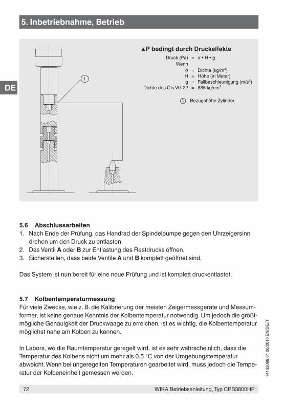
WIKA Betriebsanleitung, Typ CPB3800HP
DE
72
1413
2099
.01
06/2
016
EN/D
E/IT
5. Inbetriebnahme, Betrieb
5.6 Abschlussarbeiten1. Nach Ende der Prüfung, das Handrad der Spindelpumpe gegen den Uhrzeigersinn
drehen um den Druck zu entlasten.2. Das Ventil A oder B zur Entlastung des Restdrucks öffnen.3. Sicherstellen, dass beide Ventile A und B komplett geöffnet sind.
Das System ist nun bereit für eine neue Prüfung und ist komplett druckentlastet.
5.7 KolbentemperaturmessungFür viele Zwecke, wie z. B. die Kalibrierung der meisten Zeigermessgeräte und Messum-former, ist keine genaue Kenntnis der Kolbentemperatur notwendig. Um jedoch die größt-mögliche Genauigkeit der Druckwaage zu erreichen, ist es wichtig, die Kolbentemperatur möglichst nahe am Kolben zu kennen.
In Labors, wo die Raumtemperatur geregelt wird, ist es sehr wahrscheinlich, dass die Temperatur des Kolbens nicht um mehr als 0,5 °C von der Umgebungstemperatur abweicht. Wenn bei ungeregelten Temperaturen gearbeitet wird, muss jedoch die Tempe-ratur der Kolbeneinheit gemessen werden.
1
▲P bedingt durch DruckeffekteDruck (Pa) = σ • H • g
Wennσ = Dichte (kg/m³)H = Höhe (in Meter)g = Fallbeschleunigung (m/s²)
Dichte des Öls VG 22 = 885 kg/cm³
Bezugshöhe Zylinder
WIKA Betriebsanleitung, Typ CPB3800HP
DE
73
1413
2099
.01
06/2
016
EN/D
E/IT
5. Inbetriebnahme, Betrieb
Eine mögliche Art und Weise, dies zu tun, ist die Verwendung eines scheibenförmigen, thermistorartigen Sensorelements, das auf die Außenseite der Kolbeneinheit geklebt wird. Dieses Sensorelement sollte von der Umgebungstemperatur durch eine Abdeckung aus einem dünnen Streifen aus Polystyrol oder einem anderen Isoliermaterial isoliert und dann auf die Kolbeneinheit geklebt werden. Alternativ kann die CalibratorUnit Typ CPU6000 verwendet werden.
Es kann ein passendes Messgerät geliefert werden. Wenden Sie sich bei Bedarf bitte an DH-Budenberg/WIKA.
5.8 Reinigung der MessgeräteDieser Reinigungs-/Entfettungsprozess ist nur geeignet für Druckmessgeräte mit Bourdonfedern aus Phosphor, Bronze, Beryllium, Kupfer, Monel oder CrNi-Stahl in der Form eines „C“.
Es ist nicht ratsam, Druckmessgeräte mit Bourdonfedern aus Stahl zu entfetten, da bereits eine winzige Menge Rost Messungenauigkeiten hervorrufen und zu einem vorzeitigen Ausfall der Feder führen kann.
Diese Reinigungsmethode ist nicht geeignet für Druckmessgeräte, die mit gewundenen Bourdonfedern bestückt sind. Sie ist auch nicht für Messgeräte geeignet, die mit Sauer-stoff arbeiten, da die Funktion ohne Öl nicht sichergestellt ist. Wenden Sie sich in diesem Fall bitte an DH-Budenberg/WIKA.
AusrüstungDiese besteht aus einer Spritze und einer speziellen Nadel, die um 90° gebogen ist.
Anweisungen:1. Die Spritze mit Lösungsmittel befüllen (geeigneter Kaltreiniger zum Entfetten).2. Das Messgerät mit dem Anschluss nach oben zeigend halten, die Nadel in den
Anschluss schieben und diese vorsichtig in das Loch führen, das zur Rohrfeder führt.3. Das Lösungsmittel injizieren. Idealerweise sollte das Rohr halb voll sein.4. Das Messgerät hin und her schütteln, um das Lösungsmittel zu verteilen.5. Das Lösungsmittel mit der Spritze wieder herausziehen und das Messgerät dabei
schräg halten.6. Prüfen, ob das Lösungsmittel schwebekörperfrei und rein ist. Um sicherzugehen,
dass alles Öl entfernt wurde, den Reinigungsprozess wiederholen, bis das Lösungs-mittel klar bleibt.
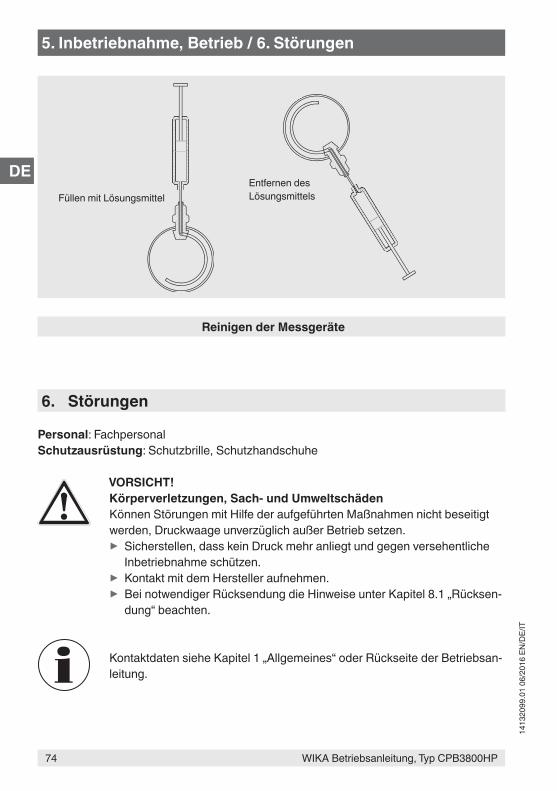
WIKA Betriebsanleitung, Typ CPB3800HP
DE
74
1413
2099
.01
06/2
016
EN/D
E/IT
5. Inbetriebnahme, Betrieb / 6. Störungen
Reinigen der Messgeräte
Füllen mit LösungsmittelEntfernen des Lösungsmittels
6. Störungen
Personal: FachpersonalSchutzausrüstung: Schutzbrille, Schutzhandschuhe
VORSICHT!Körperverletzungen, Sach- und UmweltschädenKönnen Störungen mit Hilfe der aufgeführten Maßnahmen nicht beseitigt werden, Druckwaage unverzüglich außer Betrieb setzen.
▶ Sicherstellen, dass kein Druck mehr anliegt und gegen versehentliche Inbetriebnahme schützen.
▶ Kontakt mit dem Hersteller aufnehmen. ▶ Bei notwendiger Rücksendung die Hinweise unter Kapitel 8.1 „Rücksen-dung“ beachten.
Kontaktdaten siehe Kapitel 1 „Allgemeines“ oder Rückseite der Betriebsan-leitung.
WIKA Betriebsanleitung, Typ CPB3800HP
DE
75
1413
2099
.01
06/2
016
EN/D
E/IT
6. Störungen
Störungen Ursachen MaßnahmenSystem liefert keinen Ausgangsdruck.
Keine Flüssigkeit in der Druck-waage.
Prüfen, ob die Druckwaage mit Flüssigkeit gefüllt ist. System wenn nötig mit Flüssigkeit füllen. Siehe Kapitel 5.4.1 „Befüllen des Basements mit Flüssigkeit“.
Ventil B ist offen. Ventil B schließen und noch einmal versuchen.
Zu testendes Gerät hat ein großes Volumen.
Gerät vor dem Test mit Flüssig-keit füllen.
Fehlende oder beschädigte Dichtungen aufgezeigt durch unerklärbare Leckage.
Dichtungen am System prüfen und sicherstellen, dass sie korrekt montiert und unbeschä-digt sind. Ersetzen, falls nötig.
Ventil B Handrad von Spindel gelöst.
Ventil B prüfen. Nut zur Siche-rung des Handrads an der Spindel anziehen, falls nötig.
Baugruppe Ventil B oder Ventil-sitz beschädigt.
Zustand des Ventils B und des Ventilsitzes prüfen.Ventilbaugruppe ersetzen oder Druckwaage an DH-Budenberg/WIKA zur Überholung zurück-schicken.
Wenn die Ursache nicht gefun-den werden kann.
Druckwaage an DH-Budenberg/WIKA zur Untersuchung zurück-schicken.
System liefert Druck aber der Druck fällt ab, wenn die Ventile A und B betätigt werden.
Vorgehensweise nicht korrekt. Sicherstellen, dass die korrekte Vorgehensweise angewandt wird (siehe Kapitel 5.5 „Vorgehens-weise“)
Wenn die Ursache nicht gefun-den werden kann.
Druckwaage an DH-Budenberg/WIKA zur Untersuchung zurück-schicken.
System liefert Druck aber der Druck fällt auf Null ab.
Vorgehensweise nicht korrekt. Sicherstellen, dass die korrekte Vorgehensweise angewandt wird (siehe Kapitel 5.5 „Vorgehens-weise“)
WIKA Betriebsanleitung, Typ CPB3800HP
DE
76
1413
2099
.01
06/2
016
EN/D
E/IT
Störungen Ursachen MaßnahmenSystem liefert Druck aber der Druck fällt auf Null ab.
Fehlende oder beschädigte Dichtungen aufgezeigt durch unerklärbare Leckage.
Dichtungen am System prüfen und sicherstellen, dass sie korrekt montiert und unbeschä-digt sind. Ersetzen, falls nötig.
Ventil A, Baugruppe Ventil B oder Ventilsitz beschädigt.
Zustand der Ventile A und B und des Ventilsitzes prüfen.Ventilbaugruppe ersetzen oder Druckwaage an DH-Budenberg/WIKA zur Überholung zurück-schicken.
Wenn die Ursache nicht gefun-den werden kann.
Druckwaage an DH-Budenberg/WIKA zur Untersuchung zurück-schicken.
System liefert Druck aber der Druck fällt auf einen niederen Wert ab und bleibt dann stabil.
Nicht genügend Flüssigkeit in der Druckwaage.
Füllstand im Vorratsbehälter prüfen. Vorratsbehälter mit der korrekten Flüssigkeit füllen (siehe Kapitel 5.4.1 „Befüllen des Basements mit Flüssigkeit“).
Luft im System. Zu prüfendes Bauteil mit entsprechender Flüssigkeit füllen. Falls nötig, Flüssigkeit in der Druckwaage nachfüllen.
Wenn die Ursache nicht gefun-den werden kann.
Druckwaage an DH-Budenberg/WIKA zur Untersuchung zurück-schicken.
Interne Beschädigung Druckwaage an DH-Budenberg/WIKA zur Untersuchung zurück-schicken.
Vorgehensweise nicht korrekt. Sicherstellen, dass die korrekte Vorgehensweise angewandt wird (siehe Kapitel 5.5 „Vorgehens-weise“)
Wenn die Ursache nicht gefun-den werden kann.
Druckwaage an DH-Budenberg/WIKA zur Untersuchung zurück-schicken.
6. Störungen
WIKA Betriebsanleitung, Typ CPB3800HP
DE
77
1413
2099
.01
06/2
016
EN/D
E/IT
Störungen Ursachen MaßnahmenSpindelpumpe der Druckwaage ist schwergängig, sobald die Druckwaage im Bereich unter 140 bar (2.000 lb/in²) verwendet wird.
Interne Beschädigung Druckwaage an DH-Budenberg/WIKA zur Untersuchung zurück-schicken.
Spindelpumpe der Druckwaage ist schwergängig, sobald die Druckwaage im Bereich über 140 bar (2.000 lb/in²) verwendet wird.
Vorgehensweise nicht korrekt. Sicherstellen, dass die korrekte Vorgehensweise angewandt wird (siehe Kapitel 5.5 „Vorgehens-weise“)
Wenn die Ursache nicht gefun-den werden kann.
Druckwaage an DH-Budenberg/WIKA zur Untersuchung zurück-schicken.
6. Störungen
WIKA Betriebsanleitung, Typ CPB3800HP
DE
78
1413
2099
.01
06/2
016
EN/D
E/IT
7. Wartung, Reinigung und Rekalibrierung
7. Wartung, Reinigung und Rekalibrierung
Personal: FachpersonalSchutzausrüstung: Schutzbrille, Schutzhandschuhe
Kontaktdaten siehe Kapitel 1 „Allgemeines“ oder Rückseite der Betriebsan-leitung.
7.1 Periodische WartungReparaturen sind ausschließlich vom Hersteller durchzuführen.Nur Originalteile verwenden (siehe Kapitel 10 „Zubehör“).
Für die periodische Wartung ist nur die Reinigung der Einheit und die Prüfung der Füllstände nötig. Bei normaler Verwendung ist keine weitere Wartung nötig. Falls nötig das System zum Hersteller zur Wartung zurückschicken. Genauigkeit, Überholung und Neu-Zertifizierung wird im Kapitel 7.4.1 „Überholung und Re-Zertifizierung von Druck-waagen, Wartung der Genauigkeit“ erklärt.
Flüssigkeiten, die ABS angreifen, sollten mit Vorsicht verwendet werden. Kontinuierliches Eintauchen der Gehäuseabdeckung in solche Flüssigkei-ten führt zu Beschädigungen. Verschüttete Flüssigkeit sofort entfernen.
7.2 Instandhaltung7.2.1 AllgemeinDieser Abschnitt enthält Einzelheiten zum Zerlegen der Einheit und zum Ersetzen der aufgelisteten Teile (siehe Kapitel 10 „Zubehör“). Die Kennzeichnungsnummern der Bauteile in Klammern beziehen sich auf die nachfolgende Skizze.
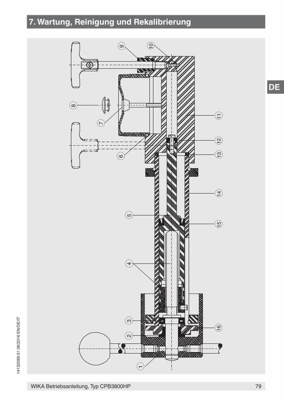
WIKA Betriebsanleitung, Typ CPB3800HP
DE
79
1413
2099
.01
06/2
016
EN/D
E/IT
8
7
65
43
2
1
9 10
1112
1314
1516
7. Wartung, Reinigung und Rekalibrierung
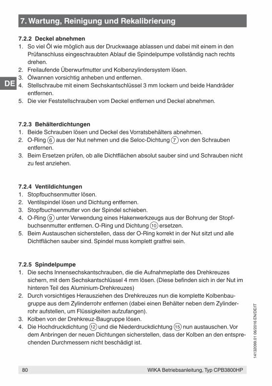
WIKA Betriebsanleitung, Typ CPB3800HP
DE
80
1413
2099
.01
06/2
016
EN/D
E/IT
7.2.2 Deckel abnehmen1. So viel Öl wie möglich aus der Druckwaage ablassen und dabei mit einem in den
Prüfanschluss eingeschraubten Ablauf die Spindelpumpe vollständig nach rechts drehen.
2. Freilaufende Überwurfmutter und Kolbenzylindersystem lösen.3. Ölwannen vorsichtig anheben und entfernen.4. Stellschraube mit einem Sechskantschlüssel 3 mm lockern und beide Handräder
entfernen.5. Die vier Feststellschrauben vom Deckel entfernen und Deckel abnehmen.
7.2.3 Behälterdichtungen1. Beide Schrauben lösen und Deckel des Vorratsbehälters abnehmen.2. O-Ring 6 aus der Nut nehmen und die Seloc-Dichtung 7 von den Schrauben
entfernen.3. Beim Ersetzen prüfen, ob alle Dichtflächen absolut sauber sind und Schrauben nicht
zu fest anziehen.
7.2.4 Ventildichtungen1. Stopfbuchsenmutter lösen.2. Ventilspindel lösen und Dichtung entfernen.3. Stopfbuchsenmutter von der Spindel schieben.4. O-Ring 9 unter Verwendung eines Hakenwerkzeugs aus der Bohrung der Stopf-
buchsenmutter entfernen. O-Ring und Dichtung 10 ersetzen.5. Beim Austauschen sicherstellen, dass der O-Ring korrekt in der Nut sitzt und alle
Dichtflächen sauber sind. Spindel muss komplett gratfrei sein.
7.2.5 Spindelpumpe1. Die sechs Innensechskantschrauben, die die Aufnahmeplatte des Drehkreuzes
sichern, mit dem Sechskantschlüssel 4 mm lösen. (Diese befinden sich in der Nut im hinteren Teil des Aluminium-Drehkreuzes)
2. Durch vorsichtiges Herausziehen des Drehkreuzes nun die komplette Kolbenbau-gruppe aus dem Zylinderrohr entfernen (dabei einen Behälter neben dem Zylinder-rohr aufstellen, um Flüssigkeiten aufzufangen).
3. Kolben von der Drehkreuz-Baugruppe lösen.4. Die Hochdruckdichtung 12 und die Niederdruckdichtung 15 nun austauschen. Vor
dem Anbringen der neuen Dichtungen sicherstellen, dass der Kolben an den entspre-chenden Durchmessern nicht beschädigt ist.
7. Wartung, Reinigung und Rekalibrierung
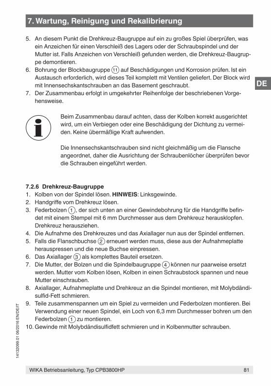
WIKA Betriebsanleitung, Typ CPB3800HP
DE
81
1413
2099
.01
06/2
016
EN/D
E/IT
5. An diesem Punkt die Drehkreuz-Baugruppe auf ein zu großes Spiel überprüfen, was ein Anzeichen für einen Verschleiß des Lagers oder der Schraubspindel und der Mutter ist. Falls Anzeichen von Verschleiß gefunden werden, die Drehkreuz-Baugrup-pe demontieren.
6. Bohrung der Blockbaugruppe 11 auf Beschädigungen und Korrosion prüfen. Ist ein Austausch erforderlich, wird dieses Teil komplett mit Ventilen geliefert. Der Block wird mit Innensechskantschrauben an das Basement geschraubt.
7. Der Zusammenbau erfolgt in umgekehrter Reihenfolge der beschriebenen Vorge-hensweise.
Beim Zusammenbau darauf achten, dass der Kolben korrekt ausgerichtet wird, um ein Verbiegen oder eine Beschädigung der Dichtung zu vermei-den. Keine übermäßige Kraft aufwenden.
Die Innensechskantschrauben sind nicht gleichmäßig um die Flansche angeordnet, daher die Ausrichtung der Schraubenlöcher überprüfen bevor die Schrauben eingeführt werden.
7.2.6 Drehkreuz-Baugruppe1. Kolben von der Spindel lösen. HINWEIS: Linksgewinde.2. Handgriffe vom Drehkreuz lösen.3. Federbolzen 1 , der sich unten an einer Gewindebohrung für die Handgriffe befin-
det mit einem Stempel mit 6 mm Durchmesser aus dem Drehkreuz herausklopfen. Drehkreuz herausziehen.
4. Die Aufnahme des Drehkreuzes und das Axiallager nun aus der Spindel entfernen.5. Falls die Flanschbuchse 2 erneuert werden muss, diese aus der Aufnahmeplatte
herauspressen und die neue Buchse einpressen.6. Das Axiallager 3 als komplettes Bauteil ersetzen.7. Die Mutter, der Bolzen und die Spindelbaugruppe 4 können nur paarweise ersetzt
werden. Mutter vom Kolben lösen, Kolben in einen Schraubstock spannen und neue Mutter einschrauben.
8. Axiallager, Aufnahmeplatte und Drehkreuz an die Spindel montieren, mit Molybdändi-sulfid-Fett schmieren.
9. Teile zusammenspannen um ein Spiel zu vermeiden und Federbolzen montieren. Bei Verwendung einer neuen Spindel, ein Loch von 6,3 mm Durchmesser bohren um den Federbolzen 1 zu montieren.
10. Gewinde mit Molybdändisulfidfett schmieren und in Kolbenmutter schrauben.
7. Wartung, Reinigung und Rekalibrierung
WIKA Betriebsanleitung, Typ CPB3800HP
DE
82
1413
2099
.01
06/2
016
EN/D
E/IT
7. Wartung, Reinigung und Rekalibrierung
7.2.7 KolbenzylindersystemDa das Kolbenzylindersystem einen großen Teil der Druckwaage ausmacht, diese immer vorsichtig behandeln und sauber halten.
Das Kolbenzylindersystem ist für hohe Genauigkeit ausgerichtet und es ist nicht empfeh-lenswert, sie zu demontieren. Ist es nötig, sie zu reinigen, die Kolben- und Zylinderboh-rung sofort ölen, um die Oberfläche zu schützen.
Ist die Einheit beschädigt, diese komplett zum Austausch oder zur Reparatur zurückschi-cken.Teile verschiedener Einheiten sind nicht untereinander austauschbar, da sie als Ganzes gewogen und ausgewertet werden müssen.
Die Seriennummer des Kolbenzylindersystems erscheint im Kalibrierzertifikat und ist auf dem Grundkörper der Einheit angegeben. Diese Nummer und die Seriennummer der Druckwaage in der Korrespondenz hinsichtlich des Kolbenzylindersystems immer angeben.
Die Anschlüsse des Kolbenzylindersystems immer mit einem Stopfen verschließen, sobald sie von der Druckwaage gelöst werden. Wird die Einheit aus irgendeinem Grund herausgenommen, immer mit dem Kopf nach unten auf dem Massenträger lagern.
Dies beinhaltet das Zerlegen der Einheit, um einfache Reparaturen auszuführen und Teile auszutauschen.
7.3 Reinigung
VORSICHT!Körperverletzungen, Sach- und UmweltschädenEine unsachgemäße Reinigung führt zu Körperverletzungen, Sach- und Umweltschäden. Messstoffreste im ausgebauten Gerät können zur Gefähr-dung von Personen, Umwelt und Einrichtung führen.
▶ Reinigungsvorgang wie folgt beschrieben durchführen.
1. Vor der Reinigung das Gerät ordnungsgemäß von der Druckversorgung trennen.2. Notwendige Schutzausrüstung verwenden.3. Das Gerät mit einem feuchten Tuch reinigen.
WIKA Betriebsanleitung, Typ CPB3800HP
DE
83
1413
2099
.01
06/2
016
EN/D
E/IT
VORSICHT!SachbeschädigungEine unsachgemäße Reinigung führt zur Beschädigung des Gerätes!
▶ Keine aggressiven Reinigungsmittel verwenden. ▶ Keine harten und spitzen Gegenstände zur Reinigung verwenden.
4. Abgebaute Prüflinge spülen bzw. säubern, um Personen und Umwelt vor Gefährdung durch anhaftende Messstoffreste zu schützen.
Reinigung der Einheit und Prüfen der FüllständeVerwendung mit ÖlDas System sauber und frei von verschüttetem Öl halten. Ölauffangwanne unter den Prüfanschlüssen reinigen. Kein lösungsmittelhaltiges Reinigungsmittel verwenden, da es die Dichtungen beschädigen kann.
Sicherstellen, dass der Vorratsbehälter genügend Flüssigkeit enthält, um die erforderli-chen Kalibrieraufgaben auszuführen. Vorratsbehälter mit derselben Flüssigkeit auffüllen, die bereits verwendet wird. Keine andere Art der Flüssigkeit oder eine andere Marke verwenden.
Wird das Öl in der Druckwaage schmutzig, Spindelpumpe verwenden, um sauberes Öl durch das Gerät zu spülen; dafür einen Ablauf in den Prüfanschluss schrauben. (Es kann ein Winkelanschlussstück verwendet werden). Vor dem Start die Spindelpumpe komplett im Uhrzeigersinn eindrehen.
Hinweise zur Rücksendung des Gerätes siehe Kapitel 8.1 „Rücksendung“.
7.4 Rekalibrierung
DKD/DAkkS-Schein - amtliche Bescheinigungen:Es wird empfohlen, das Gerät in regelmäßigen Zeitabständen von ca. 5 Jahren durch den Hersteller rekalibrieren zu lassen. Die Grundeinstellungen werden wenn notwendig korrigiert.
7. Wartung, Reinigung und Rekalibrierung
WIKA Betriebsanleitung, Typ CPB3800HP
DE
84
1413
2099
.01
06/2
016
EN/D
E/IT
7.4.1 Überholung und Re-Zertifizierung von Druckwaagen, Wartung der Genauigkeit
Die Genauigkeit der Druckwaage hängt hauptsächlich von der effektiven Querschnitts-fläche der Kolbeneinheit und von den Massen ab, die auf den Kolben gelegt werden. Die effektive Kolben-Querschnittsfläche kann durch den Verschleiß der Einheit beeinträchtigt sein. Dieser wird normalerweise von verunreinigtem Öl in der Druckwaage verursacht, das von Fremdstoffen aus zu kalibrierenden Messgeräten, von Wasser oder Chemikalen aus Messgeräten oder von durch Schmutzstoffe verursachter Korrosion stammt.
Die Massen sind aus austenitischem CrNi-Stahl gefertigt, der sehr stabil ist. Diese regel-mäßig ohne Scheuerwirkung reinigen, um Fremdstoffe zu entfernen.
7.4.2 Notwendigkeit der Überholung und Re-ZertifizierungWir empfehlen, die Druckwaage zur Überholung und Re-Zertifizierung jederzeit in den folgenden Fällen an uns zurückzuschicken:
■ Der Kolben dreht nicht frei. ■ Die Sinkrate des Kolbens ist offensichtlich höher als beim Neuteil, was die Verwen-
dung der Druckwaage schwierig macht. ■ Die Massen sind beschädigt. ■ Die Druckwaage kann aufgrund von Abnutzung oder Beschädigung der Pumpe oder
der Ventile nicht korrekt arbeiten und dies kann vom Benutzer nicht behoben werden.
Diese Druckwaage kann für die Kalibrierung von Messgeräten mit einer erwarteten Genauigkeit von 1, 0,5 oder 0,25 % verwendet werden. Solche Druckwaagen müssen nicht oft zur Überholung und Re-Zertifizierung zurückgeschickt werden; wenn sie zufrie-denstellend arbeiten, sind sie über Jahre hinweg zuverlässig. Unter diesen Umständen ist eine Überholung alle fünf Jahre angemessen.
Wird eine hohe Genauigkeit der Druckwaage gefordert, muss sie öfter zur Überholung und Re-Zertifizierung eingesandt werden. Die tatsächlichen Intervalle hängen davon ab, wie die Druckwaage verwendet wird. Eine Druckwaage in einem Labor, die mit Sorgfalt behandelt wird, muss alle zwei bis fünf Jahre zurückgeschickt werden. Eine Druckwaage, die von Ort zu Ort transportiert wird und für die Kalibrierung von hochpräzisen Messgerä-ten oder Messaufnehmern von Industrieanlagen zur direkten Druckmessung im Prozess verwendet wird, kann auch öfter als oben angegeben zurückgeschickt werden.
Die tatsächlichen Intervalle zwischen den Überholungen und Re-Zertifizierungen sollten vom Benutzer hinsichtlich der oben genannten Anmerkungen festgelegt werden und müssen die Anforderungen der Kontrollbehörde, die dafür zuständig ist, berücksichtigen.
7. Wartung, Reinigung und Rekalibrierung
WIKA Betriebsanleitung, Typ CPB3800HP
DE
85
1413
2099
.01
06/2
016
EN/D
E/IT
7.4.3 Identifizierung der MassenAlle Massen, die mit einer Druckwaage geliefert werden, sind einer Massensatznummer zugeordnet und entsprechend markiert. Falls sichergestellt werden soll, dass nur speziel-le Massen mit einer einzelnen Druckwaage oder eines Kolbenzylindersystems verwendet werden, kann auch die Seriennummer der Druckwaage bzw. der Kolbeneinheit auf den Hauptmassen vermerkt werden. Aufgrund der geringen Größe einiger Massen, können nicht alle Informationen vermerkt werden.
7.4.4 Überholung und Re-ZertifizierungFür eine bestmögliche Überholung, die Druckwaage als gesamte Einheit, zusammen mit dem Basement, dem Kolbenzylindersystem und allen Massen, zurückschicken.Das Basement kann auch selbst gewartet werden. Das Kolbenzylindersystem mit den Massen muss jedoch zur Überholung eingeschickt werden. In diesem Fall bezieht sich das Zertifikat, das nach der Überholung erstellt wird, nur auf das Kolbenzylindersys-tem und die Massensatznummern aber nicht auf das Basement, dem sie ursprünglich zugeordnet waren.
Die Basements der Druckwaage werden zerlegt, die Verrohrung gereinigt, die Dichtun-gen werden ausgetauscht und alle abgenutzten Komponenten werden, wo gewünscht, ersetzt; die Druckwaage wird wieder zusammengebaut und getestet.
Die Massen werden geprüft und, falls möglich, auf das ursprüngliche Maß gebracht. Fehlen ein oder zwei Massen oder ist eine Reparatur nicht mehr wirtschaftlich, werden sie ersetzt. Fehlen mehr als zwei Massen oder ist eine Reparatur nicht mehr wirtschaft-lich, wird der Kunde um eine Entscheidung gebeten.
Die Kolbeneinheit wird auf Genauigkeit und Sensitivität geprüft. Ist diese aus irgendeinem Grund nicht zufriedenstellend, wird ein Angebot über ein Ersatzgerät unterbreitet.
Für jede überholte Druckwaage wird ein neues Genauigkeitszertifikat erstellt. Sollte es eine leichte Änderung der Kolben-Querschnittsfläche gegeben haben, wird dies, falls auf der Bestellung nicht anders angegeben, im Zertifikat vermerkt; die Genauigkeit wird sich nicht um mehr als 0,03 % verändern.
Das Genauigkeitszertifikat des überholten Druckwaage kann zum Beispiel aufzeigen, dass die Abweichung nicht mehr als 0,05 % beträgt, während das Originalzertifikat bestätigt, dass die Abweichung 0,02 % nicht übersteigt.
Es kann für ein überholtes System ein UKAS- oder DKD/DAkkS-Zertifikat für die Kalibrie-rung erstellt werden. Einzelheiten werden auf Anfrage geliefert.
7. Wartung, Reinigung und Rekalibrierung
WIKA Betriebsanleitung, Typ CPB3800HP
DE
86
1413
2099
.01
06/2
016
EN/D
E/IT
8. Rücksendung und Entsorgung
8. Rücksendung und Entsorgung
Personal: FachpersonalSchutzausrüstung: Schutzbrille, Schutzhandschuhe
WARNUNG!Körperverletzungen, Sach- und Umweltschäden durch MessstoffresteMessstoffreste an der Druckwaage können zur Gefährdung von Personen, Umwelt und Einrichtung führen.
▶ Notwendige Schutzausrüstung tragen (siehe Kapitel 2.5 „Persönliche Schutzausrüstung“).
▶ Angaben im Sicherheitsdatenblatt für den entsprechenden Messstoff beachten.
▶ Ausgebautes Gerät spülen bzw. säubern, um Personen und Umwelt vor Gefährdung durch anhaftende Messstoffreste zu schützen.
8.1 Rücksendung
Beim Versand des Gerätes unbedingt beachten:Alle an DH-Budenberg/WIKA gelieferten Geräte müssen frei von Gefahrstoffen (Säuren, Laugen, Lösungen, etc.) sein und sind daher vor der Rücksendung zu reinigen.
WARNUNG!Körperverletzungen, Sach- und Umweltschäden durch MessstoffresteMessstoffreste an der Druckwaage können zur Gefährdung von Personen, Umwelt und Einrichtung führen.
▶ Bei Gefahrenstoffen das Sicherheitsdatenblatt für den entsprechenden Messstoff beilegen.
▶ Gerät reinigen, siehe Kapitel 7.3 „Reinigung“.
Zur Rücksendung des Gerätes die Originalverpackung oder eine geeignete Transportver-packung verwenden.
Um Schäden zu vermeiden:1. Kolbenzylindersystem in die dafür vorgesehene Transportverpackung legen (siehe
Kapitel 5.4 „Zusammenbau der Druckwaage“).2. Das Gerät mit dem Dämmmaterial in der Verpackung platzieren. Zu allen Seiten der
Transportverpackung gleichmäßig dämmen.3. Wenn möglich einen Beutel mit Trocknungsmittel der Verpackung beifügen.
WIKA Betriebsanleitung, Typ CPB3800HP
DE
87
1413
2099
.01
06/2
016
EN/D
E/IT
8. Rücksendung und Entsorgung
4. Sendung als Transport eines hochempfindlichen Messgerätes kennzeichnen.
Hinweise zur Rücksendung befinden sich in der Rubrik „Service“ auf unserer lokalen Internetseite.
8.2 EntsorgungDurch falsche Entsorgung können Gefahren für die Umwelt entstehen.Gerätekomponenten und Verpackungsmaterialien entsprechend den landesspezifischen Abfallbehandlungs- und Entsorgungsvorschriften umweltgerecht entsorgen.
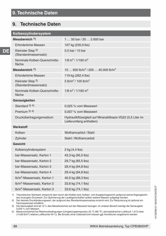
WIKA Betriebsanleitung, Typ CPB3800HP
DE
88
1413
2099
.01
06/2
016
EN/D
E/IT
9. Technische Daten
9. Technische Daten
KolbenzylindersystemMessbereich 1) 1 … 50 bar / 20 … 2.600 bar
Erforderliche Massen 107 kg (235,9 lbs)Kleinster Step 2) (Standardmassensatz)
0,5 bar / 10 bar
Nominale Kolben-Querschnitts-fläche
1/8 in² / 1/160 in²
Messbereich 1) 10 … 600 lb/in² / 200 … 40.000 lb/in²Erforderliche Massen 119 kg (262,4 lbs)Kleinster Step 2) (Standardmassensatz)
5 lb/in² / 100 lb/in²
Nominale Kolben-Querschnitts-fläche
1/8 in² / 1/160 in²
GenauigkeitenStandard 3) 4) 0,025 % vom MesswertPremium 3) 4) 0,007 % vom MesswertDruckübertragungsmedium Hydraulikflüssigkeit auf Mineralölbasis VG22 (0,5 Liter im
Lieferumfang enthalten)Werkstoff
Kolben Wolframcarbid / StahlZylinder Stahl / Wolframcarbid
GewichtKolbenzylindersystem 2 kg (4,4 lbs)bar-Massensatz, Karton 1 43,3 kg (95,5 lbs)bar-Massensatz, Karton 2 29,7 kg (65,5 lbs)bar-Massensatz, Karton 3 29,4 kg (64,8 lbs)bar-Massensatz, Karton 4 29,4 kg (64,8 lbs)lb/in²-Massensatz, Karton 1 40,5 kg (89,3 lbs)lb/in²-Massensatz, Karton 2 33,6 kg (74,1 lbs)lb/in²-Massensatz, Karton 3 33,6 kg (74,1 lbs)
1) Theoretischer Startwert; entspricht dem durch den Kolben bzw. Kolben- und Ausgleichsgewicht (aufgrund seines Eigengewich-tes) erzeugten Druckwert. Zur Optimierung der Laufeigenschaften sollten weitere Massen aufgelegt werden.
2) Der kleinste Druckänderungswert, der aufgrund des Standardmassensatzes erreicht wird. Zur Reduzierung ist optional ein Feinmassensatz erhältlich.
3) Die Genauigkeit wird ab 10 % des Messbereiches auf den Messwert bezogen. Im unteren Bereich beträgt die Genauigkeit 0,025 % vom Messert.
4) Messunsicherheit bei Referenzbedingungen (Umgebungstemperatur 20 °C (68 °F), atmosphärischer Luftdruck 1.013 mbar (14,69 lb/in²) relative Luftfeuchte 40 %). Bei Einsatz ohne CalibratorUnit müssen ggf. Korrekturen angebracht werden.
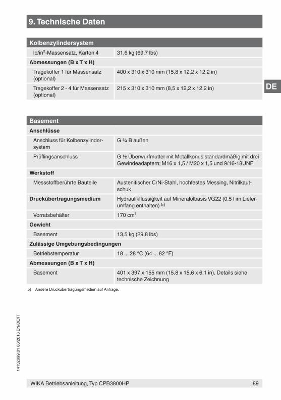
WIKA Betriebsanleitung, Typ CPB3800HP
DE
89
1413
2099
.01
06/2
016
EN/D
E/IT
9. Technische Daten
Kolbenzylindersystemlb/in²-Massensatz, Karton 4 31,6 kg (69,7 lbs)
Abmessungen (B x T x H)Tragekoffer 1 für Massensatz (optional)
400 x 310 x 310 mm (15,8 x 12,2 x 12,2 in)
Tragekoffer 2 - 4 für Massensatz (optional)
215 x 310 x 310 mm (8,5 x 12,2 x 12,2 in)
BasementAnschlüsse
Anschluss für Kolbenzylinder-system
G ¾ B außen
Prüflingsanschluss G ½ Überwurfmutter mit Metallkonus standardmäßig mit drei Gewindeadaptern; M16 x 1,5 / M20 x 1,5 und 9/16-18UNF
WerkstoffMessstoffberührte Bauteile Austenitischer CrNi-Stahl, hochfestes Messing, Nitrilkaut-
schukDruckübertragungsmedium Hydraulikflüssigkeit auf Mineralölbasis VG22 (0,5 l im Liefer-
umfang enthalten) 5)
Vorratsbehälter 170 cm³Gewicht
Basement 13,5 kg (29,8 lbs)Zulässige Umgebungsbedingungen
Betriebstemperatur 18 ... 28 °C (64 ... 82 °F)Abmessungen (B x T x H)
Basement 401 x 397 x 155 mm (15,8 x 15,6 x 6,1 in), Details siehe technische Zeichnung
5) Andere Druckübertragungsmedien auf Anfrage.
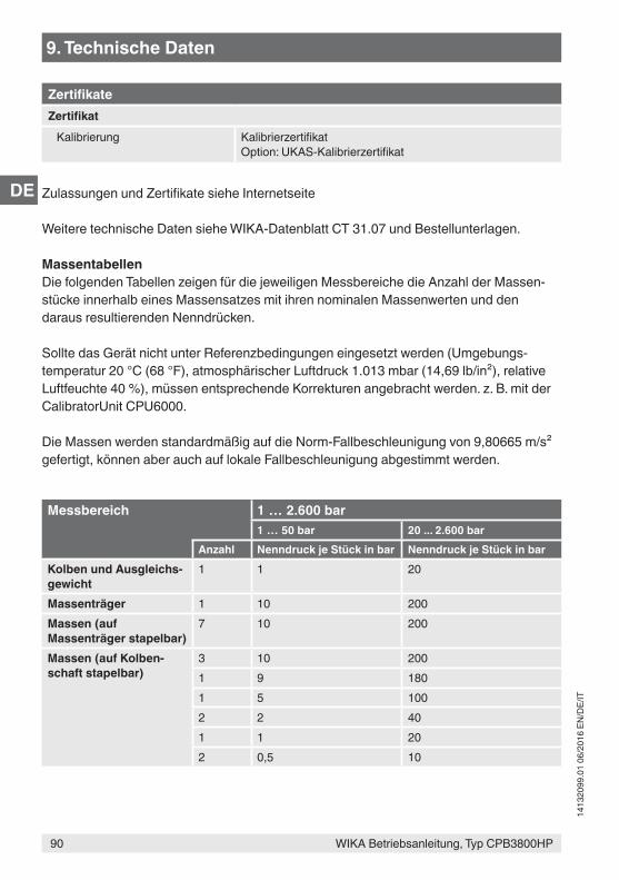
WIKA Betriebsanleitung, Typ CPB3800HP
DE
90
1413
2099
.01
06/2
016
EN/D
E/IT
9. Technische Daten
ZertifikateZertifikat
Kalibrierung KalibrierzertifikatOption: UKAS-Kalibrierzertifikat
Zulassungen und Zertifikate siehe Internetseite
Weitere technische Daten siehe WIKA-Datenblatt CT 31.07 und Bestellunterlagen.
MassentabellenDie folgenden Tabellen zeigen für die jeweiligen Messbereiche die Anzahl der Massen-stücke innerhalb eines Massensatzes mit ihren nominalen Massenwerten und den daraus resultierenden Nenndrücken.
Sollte das Gerät nicht unter Referenzbedingungen eingesetzt werden (Umgebungs-temperatur 20 °C (68 °F), atmosphärischer Luftdruck 1.013 mbar (14,69 lb/in²), relative Luftfeuchte 40 %), müssen entsprechende Korrekturen angebracht werden. z. B. mit der CalibratorUnit CPU6000.
Die Massen werden standardmäßig auf die Norm-Fallbeschleunigung von 9,80665 m/s² gefertigt, können aber auch auf lokale Fallbeschleunigung abgestimmt werden.
Messbereich 1 … 2.600 bar1 … 50 bar 20 ... 2.600 bar
Anzahl Nenndruck je Stück in bar Nenndruck je Stück in barKolben und Ausgleichs-gewicht
1 1 20
Massenträger 1 10 200Massen (auf Massenträger stapelbar)
7 10 200
Massen (auf Kolben-schaft stapelbar)
3 10 2001 9 1801 5 1002 2 401 1 202 0,5 10
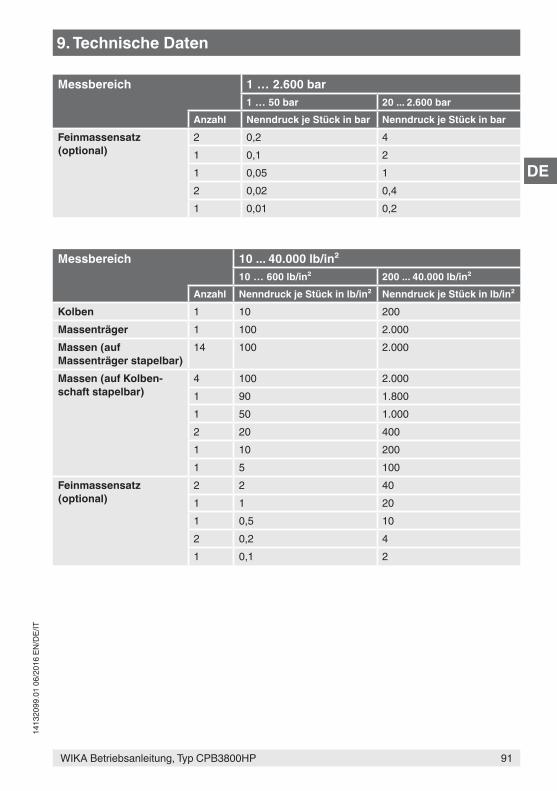
WIKA Betriebsanleitung, Typ CPB3800HP
DE
91
1413
2099
.01
06/2
016
EN/D
E/IT
9. Technische Daten
Messbereich 1 … 2.600 bar1 … 50 bar 20 ... 2.600 bar
Anzahl Nenndruck je Stück in bar Nenndruck je Stück in barFeinmassensatz(optional)
2 0,2 41 0,1 21 0,05 12 0,02 0,41 0,01 0,2
Messbereich 10 ... 40.000 lb/in²10 … 600 lb/in² 200 ... 40.000 lb/in²
Anzahl Nenndruck je Stück in lb/in² Nenndruck je Stück in lb/in²Kolben 1 10 200Massenträger 1 100 2.000Massen (auf Massenträger stapelbar)
14 100 2.000
Massen (auf Kolben-schaft stapelbar)
4 100 2.0001 90 1.8001 50 1.0002 20 4001 10 2001 5 100
Feinmassensatz(optional)
2 2 401 1 201 0,5 102 0,2 41 0,1 2
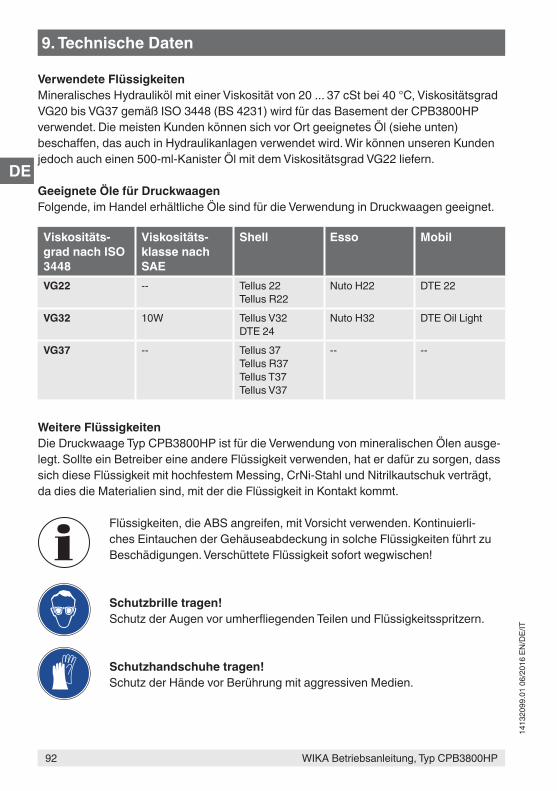
WIKA Betriebsanleitung, Typ CPB3800HP
DE
92
1413
2099
.01
06/2
016
EN/D
E/IT
9. Technische Daten
Verwendete FlüssigkeitenMineralisches Hydrauliköl mit einer Viskosität von 20 ... 37 cSt bei 40 °C, Viskositätsgrad VG20 bis VG37 gemäß ISO 3448 (BS 4231) wird für das Basement der CPB3800HP verwendet. Die meisten Kunden können sich vor Ort geeignetes Öl (siehe unten) beschaffen, das auch in Hydraulikanlagen verwendet wird. Wir können unseren Kunden jedoch auch einen 500-ml-Kanister Öl mit dem Viskositätsgrad VG22 liefern.
Geeignete Öle für DruckwaagenFolgende, im Handel erhältliche Öle sind für die Verwendung in Druckwaagen geeignet.
Viskositäts-grad nach ISO 3448
Viskositäts-klasse nach SAE
Shell Esso Mobil
VG22 -- Tellus 22Tellus R22
Nuto H22 DTE 22
VG32 10W Tellus V32DTE 24
Nuto H32 DTE Oil Light
VG37 -- Tellus 37Tellus R37Tellus T37Tellus V37
-- --
Weitere FlüssigkeitenDie Druckwaage Typ CPB3800HP ist für die Verwendung von mineralischen Ölen ausge-legt. Sollte ein Betreiber eine andere Flüssigkeit verwenden, hat er dafür zu sorgen, dass sich diese Flüssigkeit mit hochfestem Messing, CrNi-Stahl und Nitrilkautschuk verträgt, da dies die Materialien sind, mit der die Flüssigkeit in Kontakt kommt.
Flüssigkeiten, die ABS angreifen, mit Vorsicht verwenden. Kontinuierli-ches Eintauchen der Gehäuseabdeckung in solche Flüssigkeiten führt zu Beschädigungen. Verschüttete Flüssigkeit sofort wegwischen!
Schutzbrille tragen!Schutz der Augen vor umherfliegenden Teilen und Flüssigkeitsspritzern.
Schutzhandschuhe tragen!Schutz der Hände vor Berührung mit aggressiven Medien.
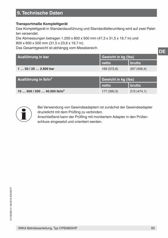
WIKA Betriebsanleitung, Typ CPB3800HP
DE
93
1413
2099
.01
06/2
016
EN/D
E/IT
9. Technische Daten
Transportmaße KomplettgerätDas Komplettgerät in Standardausführung und Standardlieferumfang wird auf zwei Palet-ten versendet.Die Abmessungen betragen 1.200 x 800 x 500 mm (47,3 x 31,5 x 19,7 in) und 800 x 600 x 500 mm (31,5 x 23,6 x 19,7 in).Das Gesamtgewicht ist abhängig vom Messbereich.
Ausführung in bar Gewicht in kg (lbs)netto brutto
1 … 50 / 20 … 2.600 bar 169 (372,6) 207 (456,4)
Ausführung in lb/in² Gewicht in kg (lbs)netto brutto
10 … 600 / 200 … 40.000 lb/in² 177 (390,3) 215 (474,1)
Bei Verwendung von Gewindeadaptern ist zunächst der Gewindeadapter druckdicht mit dem Prüfling zu verbinden.Anschließend kann der Prüfling mit montiertem Adapter in den Prüfan-schluss eingesetzt und orientiert werden.
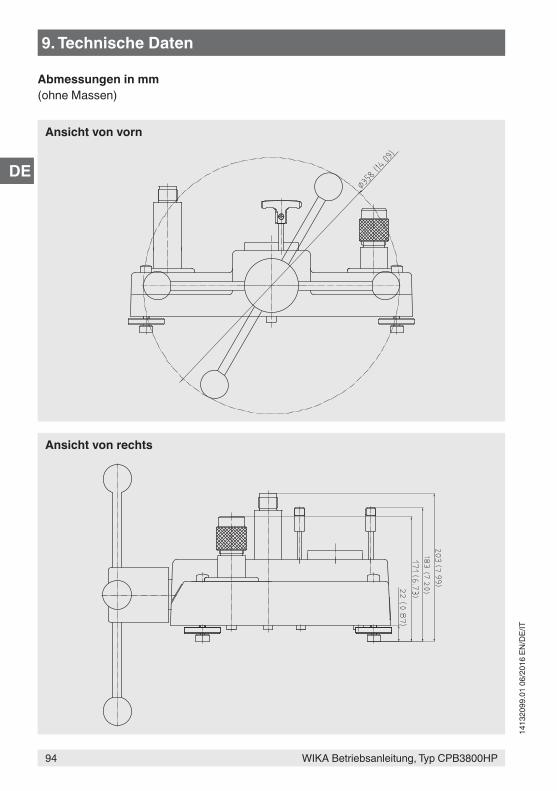
WIKA Betriebsanleitung, Typ CPB3800HP
DE
94
1413
2099
.01
06/2
016
EN/D
E/IT
9. Technische Daten
Abmessungen in mm(ohne Massen)
Ansicht von vorn
Ansicht von rechts
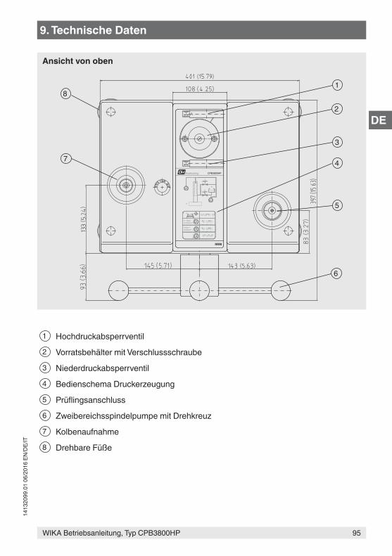
WIKA Betriebsanleitung, Typ CPB3800HP
DE
95
1413
2099
.01
06/2
016
EN/D
E/IT
A
140bar +2000lb/in² +
0
0-140bar0-2000lb/in²
R
BA P
AP B
AB P
A B P P
P
B
A
R
CPB3800HP
8
7
1
2
3
4
5
6
9. Technische Daten
1 Hochdruckabsperrventil
2 Vorratsbehälter mit Verschlussschraube
3 Niederdruckabsperrventil
4 Bedienschema Druckerzeugung
5 Prüflingsanschluss
6 Zweibereichsspindelpumpe mit Drehkreuz
7 Kolbenaufnahme
8 Drehbare Füße
Ansicht von oben
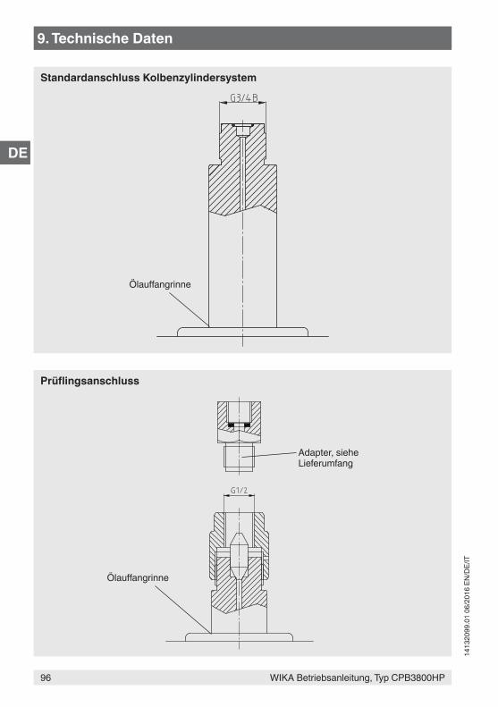
WIKA Betriebsanleitung, Typ CPB3800HP
DE
96
1413
2099
.01
06/2
016
EN/D
E/IT
9. Technische Daten
Ölauffangrinne
Adapter, siehe Lieferumfang
Prüflingsanschluss
Ölauffangrinne
Standardanschluss Kolbenzylindersystem
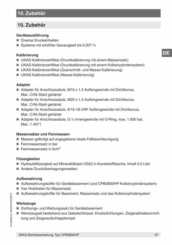
WIKA Betriebsanleitung, Typ CPB3800HP
DE
97
1413
2099
.01
06/2
016
EN/D
E/IT
10. Zubehör
Geräteausführung ■ Diverse Druckeinheiten ■ Systeme mit erhöhter Genauigkeit bis 0,007 %
Kalibrierung ■ UKAS-Kalibrierzertifikat (Druckkalibrierung mit einem Massensatz) ■ UKAS-Kalibrierzertifikat (Druckkalibrierung mit einem Kolbenzylindersystem) ■ UKAS-Kalibrierzertifikat (Querschnitt- und Masse-Kalibrierung) ■ UKAS-Kalibrierzertifikat (Masse-Kalibrierung)
Adapter ■ Adapter für Anschlusssäule, M16 x 1,5 Außengewinde mit Dichtkonus,
Mat.: CrNi-Stahl gehärtet ■ Adapter für Anschlusssäule, M20 x 1,5 Außengewinde mit Dichtkonus,
Mat.: CrNi-Stahl gehärtet ■ Adapter für Anschlusssäule, 9/16-18 UNF Außengewinde mit Dichtkonus,
Mat.: CrNi-Stahl gehärtet ■ Adapter für Anschlusssäule, G ½ Innengewinde mit O-Ring, max. 1.600 bar,
Mat.: 1.4571
Massensätze und Feinmassen ■ Massen gefertigt auf angegebene lokale Fallbeschleunigung ■ Feinmassensatz in bar ■ Feinmassensatz in lb/in²
Flüssigkeiten ■ Hydraulikflüssigkeit auf Mineralölbasis VG22 in Kunststoffflasche, Inhalt 0,5 Liter ■ Andere Druckübertragungsmedien
Aufbewahrung ■ Aufbewahrungskoffer für Gerätebasement (und CPB3800HP Kolbenzylindersystem) ■ Vier Holzkisten für Massensatz ■ Aufbewahrungskoffer für Basement, Massensatz und das Kolbenzylindersystem
Werkzeuge ■ Dichtungs- und Wartungssatz für Gerätebasement ■ Werkzeugset bestehend aus Gabelschlüssel, Ersatzdichtungen, Zeigerabhebevorrich-
tung und Zeigeraufschlagstempel
10. Zubehör

WIKA Betriebsanleitung, Typ CPB3800HP
DE
98
1413
2099
.01
06/2
016
EN/D
E/IT
99WIKA manuale d'uso, modello CPB3800HP
IT
1413
2099
.01
06/2
016
EN/D
E/IT
1. Informazioni generali 1012. Sicurezza 102
2.1 Legenda dei simboli . . . . . . . . . . . . . . . . . . . 1022.2 Destinazione d'uso . . . . . . . . . . . . . . . . . . . 1022.3 Uso improprio . . . . . . . . . . . . . . . . . . . . . 103
2.3.1 Manipolazione di oli minerali . . . . . . . . . . . . . . 1042.3.2 Altri fluidi . . . . . . . . . . . . . . . . . . . . . 1052.3.3 Sollevamento delle masse . . . . . . . . . . . . . . . 105
2.4 Qualificazione del personale . . . . . . . . . . . . . . . . 1052.5 Dispositivi di protezione personale . . . . . . . . . . . . . . 1062.6 Etichettatura, simboli per la sicurezza . . . . . . . . . . . . . 107
3. Esecuzione e funzioni 1083.1 Descrizione . . . . . . . . . . . . . . . . . . . . . . 1083.2 Scopo di fornitura . . . . . . . . . . . . . . . . . . . . 1083.3 Base . . . . . . . . . . . . . . . . . . . . . . . . 108
3.3.1 Pompa a mandrino. . . . . . . . . . . . . . . . . . 1103.3.2 Serbatoio . . . . . . . . . . . . . . . . . . . . . 1103.3.3 Valvole di regolazione . . . . . . . . . . . . . . . . 1103.3.4 Blocchi di connessione . . . . . . . . . . . . . . . . 110
3.4 Gruppo pistone . . . . . . . . . . . . . . . . . . . . . 1113.5 Funzioni . . . . . . . . . . . . . . . . . . . . . . . 112
4. Trasporto, imballo e stoccaggio 1134.1 Trasporto . . . . . . . . . . . . . . . . . . . . . . . 1134.2 Imballaggio e stoccaggio . . . . . . . . . . . . . . . . . 113
5. Messa in servizio, funzionamento 1145.1 Disimballaggio della bilancia a pesi . . . . . . . . . . . . . . 1145.2 Condizioni ambientali . . . . . . . . . . . . . . . . . . . 1155.3 Installazione della base . . . . . . . . . . . . . . . . . . 1155.4 Montaggio della bilancia a pesi . . . . . . . . . . . . . . . 115
5.4.1 Riempimento della base con il fluido. . . . . . . . . . . . 1165.4.2 Prova successiva al montaggio . . . . . . . . . . . . . 116
5.5 Procedura . . . . . . . . . . . . . . . . . . . . . . 1175.5.1 Caricamento di pressione . . . . . . . . . . . . . . . 1185.5.2 Durante la taratura . . . . . . . . . . . . . . . . . . 1185.5.3 Valori di riferimento . . . . . . . . . . . . . . . . . 119
5.6 Completamento. . . . . . . . . . . . . . . . . . . . . 1205.7 Misura della temperatura del pistone . . . . . . . . . . . . . 1205.8 Pulizia degli strumenti di misura . . . . . . . . . . . . . . . 121
ContenutiContenuti
100 WIKA manuale d'uso, modello CPB3800HP
IT
1413
2099
.01
06/2
016
EN/D
E/IT
6. Malfunzionamenti e guasti 1227. Manutenzione, pulizia e ricertificazione 126
7.1 Manutenzione periodica . . . . . . . . . . . . . . . . . . 1267.2 Manutenzione correttiva . . . . . . . . . . . . . . . . . . 126
7.2.1 Informazioni generali . . . . . . . . . . . . . . . . . 1267.2.2 Rimozione della copertura . . . . . . . . . . . . . . . 1287.2.3 Guarnizioni del serbatoio . . . . . . . . . . . . . . . 1287.2.4 Guarnizioni della valvola . . . . . . . . . . . . . . . . 1287.2.5 Pompa a mandrino. . . . . . . . . . . . . . . . . . 1287.2.6 Assemblaggio del volantino a stella . . . . . . . . . . . . 1297.2.7 Accoppiamento pistone-cilindro . . . . . . . . . . . . . 129
7.3 Pulizia . . . . . . . . . . . . . . . . . . . . . . . . 1307.4 Ricertificazione . . . . . . . . . . . . . . . . . . . . . 131
7.4.1 Revisione e ricertificazione delle bilance di pressione, manutenzione dell'accuratezza . . . . . . . . . . . . . . . . . . 131
7.4.2 Necessità di revisione e ricertificazione. . . . . . . . . . . 1327.4.3 Identificazione delle masse . . . . . . . . . . . . . . . 1327.4.4 Revisione e ricertificazione . . . . . . . . . . . . . . . 133
8. Resi e smaltimento 1348.1 Resi. . . . . . . . . . . . . . . . . . . . . . . . . 1348.2 Smaltimento . . . . . . . . . . . . . . . . . . . . . . 135
9. Specifiche tecniche 13610. Accessori 145
La dichiarazione di conformità è disponibile online sul sito www.wika.it.
Contenuti
101WIKA manuale d'uso, modello CPB3800HP
IT
1413
2099
.01
06/2
016
EN/D
E/IT
1. Informazioni generali
■ La bilancia a presi per alte pressioni, modello CPB3800HP, descritta nel manuale d'uso è stata progettata e fabbricata secondo lo stato dell'arte della tecnica. Tutti i componenti sono sottoposti a severi controlli di qualità e ambientali durante la produzione. I nostri sistemi di qualità sono certificati ISO 9001 e ISO 14001.
■ Questo manuale d'uso contiene importanti informazioni sull'uso dello strumento. Lavorare in sicurezza implica il rispetto delle istruzioni di sicurezza e di funzionamento.
■ Osservare le normative locali in tema di prevenzione incidenti e le regole di sicurezza generali per il campo d'impiego dello strumento.
■ Il manuale d'uso è parte dello strumento e deve essere conservato nelle immediate vicinanze dello stesso e facilmente accessibile in ogni momento al personale qualificato. Trasferire le istruzioni d'uso e manutenzione all'operatore o al possessore successivo.
■ Il manuale d‘uso deve essere letto con attenzione e compreso dal personale qualificato prima dell‘inizio di qualsiasi attività.
■ Si applicano le nostre condizioni generali di vendita, allegate alla conferma d’ordine.
■ Soggetto a modifiche tecniche.
■ Le tarature di fabbrica / DKD/DAkkS/ACCREDIA sono effettuate secondo gli standard internazionali.
■ Ulteriori informazioni:DH-BudenbergDivisione del gruppo WIKA Instruments Ltd.- Indirizzo Internet: www.wika.it- Scheda tecnica prodotto: CT 31.07- Consulenze tecniche ed applicative Tel.: +44 844 4060086
Fax: +44 844 [email protected]
1. Informazioni generali
102 WIKA manuale d'uso, modello CPB3800HP
IT
1413
2099
.01
06/2
016
EN/D
E/IT
WIKA Italia Srl & C. Sas- Indirizzo Internet: www.wika.it- Scheda tecnica prodotto: CT 31.07- Consulenze tecniche ed applicative: Tel.: +39 02 93861-1
Fax: +39 02 [email protected]
2. Sicurezza
2.1 Legenda dei simboli
ATTENZIONE!... indica una situazione di potenziale pericolo che, se non evitata, può causare ferite gravi o morte.
CAUTELA!... indica una situazione di potenziale pericolo che, se non evitata, può causare ferite lievi o danni a cose o all'ambiente.
Informazione... fornisce suggerimenti utili e raccomandazioni per l'utilizzo efficiente e senza problemi dello strumento.
2.2 Destinazione d'usoLe bilance di pressione sono gli strumenti più accurati per la taratura di strumenti di misura meccanici o elettronici della pressione presenti sul mercato. Nella misurazione diretta della pressione definita come il quoziente tra forza e superficie (p = F/A), le bilance di pressione sono omologate come campioni primari.
Il componente principale della bilancia a pesi modello CPB3800HP è quindi un accoppiamento pistone-cilindro fabbricato con estrema precisione, che viene caricato con set di masse in modo tale da generare i singoli punti di prova. Il set di masse è proporzionale alla pressione obiettivo e ciò viene ottenuto tramite delle masse dimensionate in maniera ottimale. La pressione massima non deve essere superiore a 2.600 bar (40.000 lb/in²).
1. Informazioni generali / 2. Sicurezza
103WIKA manuale d'uso, modello CPB3800HP
IT
1413
2099
.01
06/2
016
EN/D
E/IT
La pressione viene impostata tramite una pompa a mandrino integrata, a regolazione fine e a doppia area di precisione. Non appena l'accoppiamento di misura raggiunge l'equilibrio, avviene un bilanciamento delle forze tra la pressione ed il carico delle masse applicato. Lo strumento in prova può quindi essere tarato o regolato.
Grazie al suo funzionamento autonomo (generazione della pressione integrata e principio di misura puramente meccanico), il modello CPB3800HP è ideale per interventi di manutenzione e assistenza sul campo.
Non è consentito l'utilizzo di questo strumento in aree pericolose!
Lo strumento è stato progettato e costruito esclusivamente per la sua destinazione d'uso e può essere impiegato solo per questa.
Le specifiche tecniche riportate in questo manuale d'uso devono essere rispettate. L'uso improprio dello strumento al di fuori delle specifiche tecniche richiede che lo strumento venga messo immediatamente fuori servizio e che venga ispezionato da un tecnico di servizio WIKA autorizzato.
Maneggiare gli strumenti meccanici di misura di precisione con la dovuta cautela (proteggerli da umidità, impatti, forti campi magnetici, elettricità statica e temperature estreme, non inserire alcun oggetto nello strumento o nelle sue aperture). Connettori e prese devono essere protette dalle contaminazioni.
Il costruttore non è responsabile per reclami di qualsiasi natura in caso di utilizzo dello strumento al di fuori della sua destinazione d'uso.
2.3 Uso improprio
ATTENZIONE!Lesioni derivanti da uso improprioL'uso improprio dello strumento può provocare situazioni pericolose o lesioni.
▶ Astenersi dall'effettuare modifiche non autorizzate allo strumento. ▶ Non utilizzare lo strumento all'interno di aree pericolose. ▶ Non utilizzare lo strumento con fluidi abrasivi o viscosi.
Qualsiasi utilizzo dello strumento al di fuori o diverso da quello previsto è considerato uso improprio.
2. Sicurezza
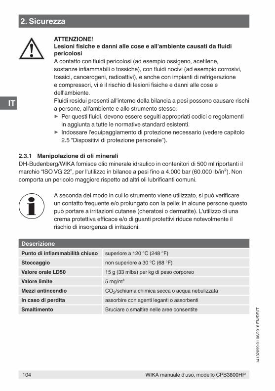
104 WIKA manuale d'uso, modello CPB3800HP
IT
1413
2099
.01
06/2
016
EN/D
E/IT
ATTENZIONE!Lesioni fisiche e danni alle cose e all'ambiente causati da fluidi pericolosiA contatto con fluidi pericolosi (ad esempio ossigeno, acetilene, sostanze infiammabili o tossiche), con fluidi nocivi (ad esempio corrosivi, tossici, cancerogeni, radioattivi), e anche con impianti di refrigerazione e compressori, vi è il rischio di lesioni fisiche e danni alle cose e dell'ambiente.Fluidi residui presenti all'interno della bilancia a pesi possono causare rischi a persone, all'ambiente e allo strumento stesso.
▶ Per questi fluidi, devono essere seguiti appropriati codici o regolamenti in aggiunta a tutte le normative standard esistenti.
▶ Indossare l'equipaggiamento di protezione necessario (vedere capitolo 2.5 “Dispositivi di protezione personale”).
2.3.1 Manipolazione di oli mineraliDH-Budenberg/WIKA fornisce olio minerale idraulico in contenitori di 500 ml riportanti il marchio “ISO VG 22”, per l'utilizzo in bilance a pesi fino a 4.000 bar (60.000 lb/in²). Non comporta un pericolo maggiore rispetto ad altri oli lubrificanti comuni.
A seconda del modo in cui lo strumento viene utilizzato, si può verificare un contatto frequente e/o prolungato con la pelle; in alcune persone questo può portare a irritazioni cutanee (cheratosi o dermatite). L'utilizzo di una crema protettiva efficace e/o di guanti protettivi riduce notevolmente il rischio di insorgenza di irritazioni.
DescrizionePunto di infiammabilità chiuso superiore a 120 °C (248 °F)Stoccaggio non superiore a 30 °C (68 °F)Valore orale LD50 15 g (33 mlbs) per kg di peso corporeoValore limite 5 mg/m³Mezzi antincendio CO2/schiuma chimica secca o acqua nebulizzataIn caso di perdita assorbire con agenti leganti o assorbentiSmaltimento Bruciare o smaltire nelle aree consentite
2. Sicurezza
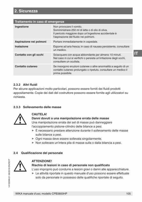
105WIKA manuale d'uso, modello CPB3800HP
IT
1413
2099
.01
06/2
016
EN/D
E/IT
Trattamento in caso di emergenzaIngestione Non provocare il vomito.
Somministrare 250 ml di latte o di olio di oliva.Il pericolo maggiore dopo un'ingestione accidentale è l'aspirazione del fluido nei polmoni.
Aspirazione nei polmoni Portare immediatamente in ospedale.Inalazione Esporre ad aria fresca; in caso di nausea persistente, consultare
un medico.Contatto con gli occhi Sciacquare con acqua abbondante per almeno 10 minuti.
Nel caso in cui si verifichi o persista un'irritazione degli occhi, consultare un oculista.
Contatto cutaneo Se insorgono eruzioni cutanee o altre anormalità a seguito di un contatto cutaneo prolungato o ripetuto, consultare un medico il prima possibile.
2.3.2 Altri fluidiPer alcune applicazioni molto particolari, possono essere forniti dei fluidi prodotti appositamente. Copie dei dati del costruttore possono essere fornite agli utilizzatori su richiesta.
2.3.3 Sollevamento delle masse
CAUTELA!Danni dovuti a una manipolazione errata delle masseUna manipolazione errata dei set di masse può danneggiare l'accoppiamento pistone-cilindro delle bilance a pesi.
▶ È necessario prestare attenzione durante il sollevamento delle masse sulle bilance a pesi.
▶ Ogni massa deve essere sollevata singolarmente. ▶ Non sollevare un'intera pila di masse sulla o dalla bilancia a pesi.
2.4 Qualificazione del personale
ATTENZIONE!Rischio di lesioni in caso di personale non qualificatoL'uso improprio può condurre a lesioni gravi o danni alle apparecchiature.
▶ Le attività riportate in questo manuale d'uso possono essere effettuate solo da personale in possesso delle qualifiche riportate di seguito.
2. Sicurezza
106 WIKA manuale d'uso, modello CPB3800HP
IT
1413
2099
.01
06/2
016
EN/D
E/IT
Personale qualificatoPer personale qualificato, autorizzato dall'operatore, si intende personale che, sulla base della sua formazione tecnica, della conoscenza della tecnologia di misura e controllo e sulla sua esperienza e conoscenza delle normative specifiche del paese, normative e direttive correnti, sia in grado di effettuare il lavoro descritto e di riconoscere autonomamente potenziali pericoli.
Eventuali condizioni operative speciali richiedono inoltre conoscenze specifiche, es. fluidi aggressivi.
DH-Budenberg/WIKA può fornire corsi di formazione per un uso corretto dei prodotti. Per informazioni più dettagliate al riguardo, contattare l'ufficio locale.
2.5 Dispositivi di protezione personaleI dispositivi protettivi personali sono progettati per proteggere il personale qualificato da pericoli che possono danneggiare la sicurezza e la salute durante il lavoro. Nell'esecuzione delle diverse attività con lo strumento, il personale qualificato deve indossare i dispositivi di protezione.
Seguire le istruzioni riportate nell'area di lavoro riguardanti i dispositivi di protezione!
L'attrezzatura necessaria per la protezione individuale deve essere fornita dall'azienda.
Indossare occhiali protettivi!Proteggere gli occhi da particelle volatili o spruzzi di liquidi.
Indossare guanti protettivi!Proteggere le mani dal contatto con agenti aggressivi.
2. Sicurezza
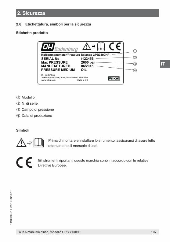
107WIKA manuale d'uso, modello CPB3800HP
IT
1413
2099
.01
06/2
016
EN/D
E/IT
2.6 Etichettatura, simboli per la sicurezza
Etichetta prodotto
Modello
N. di serie
Campo di pressione
Data di produzione
Simboli
Prima di montare e installare lo strumento, assicurarsi di avere letto attentamente il manuale d'uso!
Gli strumenti riportanti questo marchio sono in accordo con le relative Direttive Europee.
Kolbenmanometer/Pressure Balance CPB3800HP
OILPRESSURE MEDIUMDH Budenberg10 Huntsman Drive, Irlam, Manchester, M44 5EGwww.wika.com Made in UK
MANUFACTUREDMax PRESSURESERIAL No /123456
2600 bar06/2015
2. Sicurezza
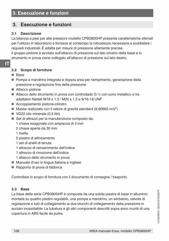
108 WIKA manuale d'uso, modello CPB3800HP
IT
1413
2099
.01
06/2
016
EN/D
E/IT
3. Esecuzione e funzioni3.1 DescrizioneLa bilancia a pesi per alte pressioni modello CPB3800HP presenta caratteristiche ottimali per l'utilizzo in laboratorio e fornisce al contempo la robustezza necessaria a soddisfare i requisiti industriali. È adatta per misure di pressione altamente precise.Il gruppo pistone è avvitato sull'attacco di pressione sul lato sinistro della base e lo strumento in prova viene collegato all'attacco di pressione sul lato destro.
3.2 Scopo di fornitura ■ Base ■ Pompa a mandrino integrata a doppia area per riempimento, generazione della
pressione e regolazione fine della pressione ■ Attacco pistone ■ Attacco dello strumento in prova con controdado G ½ con cono metallico e tre
adattatori filettati M16 x 1,5 / M20 x 1,5 e 9/16-18 UNF ■ Accoppiamento pistone-cilindro ■ Masse realizzate con il valore di gravità standard (9,80665 m/s²) ■ VG22 olio minerale (0,5 litri) ■ Set di attrezzi per la manutenzione composto da:
1 chiave esagonale con ampiezza di 3 mm2 chiave aperte da 30 mm1 livella5 piastre di allineamento1 set di anelli di tenuta1 attrezzo di reinserimento dell'indice1 attrezzo di rimozione dell'indice1 attacco dello strumento in prova
■ Manuale d'uso in lingua italiana e inglese ■ Rapporto di prova di fabbrica
Controllare lo scopo di fornitura con il documento di consegna / trasporto.
3.3 BaseLa base della serie CPB3800HP è composta da una solida piastra di base in alluminio montata su quattro piedini regolabili, una pompa a mandrino, un serbatoio, valvole di regolazione e tubi di collegamento ai due blocchi di collegamento della pressione in acciaio inossidabile. Le tubature e gli altri componenti descritti sopra sono muniti di una copertura in ABS facile da pulire.
3. Esecuzione e funzioni
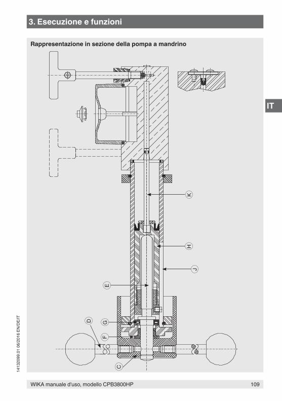
109WIKA manuale d'uso, modello CPB3800HP
IT
1413
2099
.01
06/2
016
EN/D
E/IT
E
D GF
C
JH
K
Rappresentazione in sezione della pompa a mandrino
3. Esecuzione e funzioni
110 WIKA manuale d'uso, modello CPB3800HP
IT
1413
2099
.01
06/2
016
EN/D
E/IT
3.3.1 Pompa a mandrinoLa pompa a mandrino è avvitata al serbatoio/blocco cilindro ad alta pressione, a sua volta fissato alla base. Di seguito viene mostrata una rappresentazione in sezione della pompa. Il volantino rotante C comandato tramite le impugnature D è fissato a un mandrino filettato E . Il mandrino E è supportato da un cuscinetto sinterizzato F .Non appena il mandrino viene ruotato, esso spinge in avanti un pistone di pressione non rotante H e K , la forza di spinta è smorzata da un cuscinetto di spinta a spillo G . Il diametro grande del pistone H nel cilindro della pompa J effettua il riempimento del circuito di pressione e genera una pressione iniziale fino a circa 140 bar (2.000 lb/in²). Il diametro piccolo del pistone K nel serbatoio/blocco cilindro ad alta pressione fornisce valori di pressione di prova maggiori fino a 2.600 bar (40.000 lb/in²).
3.3.2 SerbatoioUn serbatoio per fluidi è posizionato sulla parte superiore del blocco cilindro ad alta pressione. Il serbatoio è dotato di una copertura semitrasparente per consentire il monitoraggio del livello del serbatoio. Un tappo posto al centro della copertura del serbatoio consente il riempimento o il rabbocco del serbatoio (esso viene rimosso quando la bilancia a pesi è in funzione). Il serbatoio contiene la quantità di fluido necessaria (circa 150 cm³) per garantire il normale funzionamento della bilancia a pesi.Volume di dislocamento del pistone di bassa pressione = 60 cm³Volume di dislocamento del pistone di alta pressione = 10 cm³
3.3.3 Valvole di regolazioneSulla parte superiore del serbatoio/blocco cilindro ad alta pressione sono posizionate due valvole di regolazione. I meccanismi delle valvole di regolazione si trovano all'interno del serbatoio/blocco cilindro ad alta pressione e regolano il flusso del fluido attraverso dei fori interni del serbatoio/blocco cilindro ad alta pressione. La valvola posteriore viene denominata valvola A ed è utilizzata per regolare l'uscita dal pistone della pompa a mandrino con il diametro maggiore. La valvola anteriore viene denominata valvola B ed è utilizzata per regolare il flusso del fluido verso e dal serbatoio.
3.3.4 Blocchi di connessioneI tubi di alimentazione della pressione della pompa a mandrino sono collegati alla base con due attacchi di pressione. Le filettature degli attacchi di pressione sporgono dal coperchio della base. Il gruppo pistone può essere avvitato direttamente su questi attacchi filettati oltre che su attacchi di strumenti di misura di misure diverse, da avvitare mediante adattatori filettati. Sul coperchio sono montate delle vaschette attorno agli attacchi filettati dei blocchi di connessione, che servono per il recupero dell'olio che fuoriesce dall'attacco di prova durante le operazioni di collegamento e rimozione degli strumenti di misura.
3. Esecuzione e funzioni
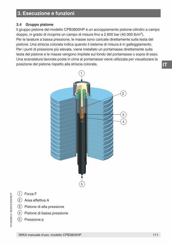
111WIKA manuale d'uso, modello CPB3800HP
IT
1413
2099
.01
06/2
016
EN/D
E/IT
3.4 Gruppo pistoneIl gruppo pistone del modello CPB3800HP è un accoppiamento pistone-cilindro a campo doppio, in grado di ricoprire un campo di misura fino a 2.600 bar (40.000 lb/in²).Per le tarature a bassa pressione, le masse sono caricate direttamente sulla testa del pistone. Una striscia colorata indica quando il sistema di misura è in galleggiamento. Per i punti di pressione più elevata, viene installato un portamasse direttamente sulla testa del pistone e le masse vengono impilate sul fondo del portamasse o sopra di esso. Una scanalatura lavorata posta in cima al portamasse viene utilizzata per visualizzare la posizione del pistone rispetto alla striscia colorata.
1 Forza F2 Area effettiva A3 Pistone di alta pressione4 Pistone di bassa pressione5 Pressione p
5
1
3
4
2
3. Esecuzione e funzioni
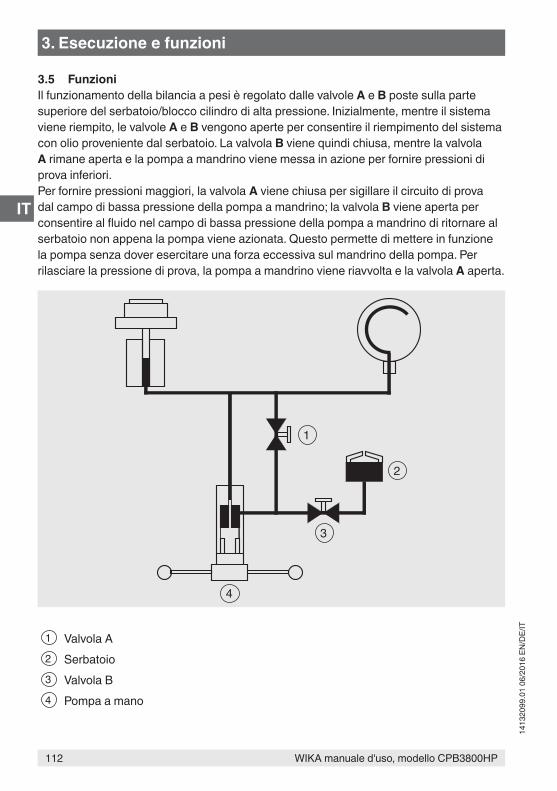
112 WIKA manuale d'uso, modello CPB3800HP
IT
1413
2099
.01
06/2
016
EN/D
E/IT
3.5 FunzioniIl funzionamento della bilancia a pesi è regolato dalle valvole A e B poste sulla parte superiore del serbatoio/blocco cilindro di alta pressione. Inizialmente, mentre il sistema viene riempito, le valvole A e B vengono aperte per consentire il riempimento del sistema con olio proveniente dal serbatoio. La valvola B viene quindi chiusa, mentre la valvola A rimane aperta e la pompa a mandrino viene messa in azione per fornire pressioni di prova inferiori.Per fornire pressioni maggiori, la valvola A viene chiusa per sigillare il circuito di prova dal campo di bassa pressione della pompa a mandrino; la valvola B viene aperta per consentire al fluido nel campo di bassa pressione della pompa a mandrino di ritornare al serbatoio non appena la pompa viene azionata. Questo permette di mettere in funzione la pompa senza dover esercitare una forza eccessiva sul mandrino della pompa. Per rilasciare la pressione di prova, la pompa a mandrino viene riavvolta e la valvola A aperta.
1 Valvola A2 Serbatoio3 Valvola B4 Pompa a mano
2
1
4
3
3. Esecuzione e funzioni
113WIKA manuale d'uso, modello CPB3800HP
IT
1413
2099
.01
06/2
016
EN/D
E/IT
4. Trasporto, imballo e stoccaggio4.1 TrasportoVerificare che la bilancia a pesi per alte pressioni modello CPB3800HP non abbia subito danni durante il trasporto. Danni evidenti devono essere segnalati tempestivamente.
CAUTELA!Danni dovuti a trasporto improprioCon un trasporto non corretto, lo strumento può subire danni gravi.
▶ Quando le merci imballate si scaricano al momento della consegna, così come durante il trasporto interno, procedere con cautela e osservare i simboli riportati sull'imballo.
▶ In caso di trasporti interni, osservare le istruzioni riportate nel capitolo 4.2 “Imballaggio e stoccaggio”.
Se lo strumento viene spostato da un ambiente freddo a uno caldo, la formazione di condensa può portare a un malfunzionamento dello strumento. Prima di mettere in funzione lo strumento, attendere che la temperatura dello strumento e quella dell'ambiente si equalizzino.
4.2 Imballaggio e stoccaggioRimuovere l'imballo solo appena prima dell'installazione.Conservare l'imballo per proteggere lo strumento in successivi trasporti (es. variazione del sito di installazione, invio in riparazione).
Se ordinate, le masse vengono spedite nel cartone e non nelle rispettive custodie di legno.Le custodie di legno non sono adatte per essere utilizzate come contenitore per la spedizione.
Condizioni consentite per lo stoccaggio: ■ Temperatura di stoccaggio: -10 ... +50 °C ■ Umidità: 35 ... 85 % di umidità relativa per lo strumento base e il set di masse
35 ... 65 % di umidità relativa per l'accoppiamento pistone-cilindro (nessuna condensazione)
Evitare l'esposizione ai seguenti fattori: ■ Esposizione diretta al sole o prossimità con oggetti molto caldi ■ Vibrazioni e shock meccanici (posare lo strumento in modo energico) ■ Fuliggine, vapori, polvere e gas corrosivi ■ Ambienti pericolosi, atmosfere infiammabili ■ Fluidi corrosivi
4. Trasporto, imballo e stoccaggio
114 WIKA manuale d'uso, modello CPB3800HP
IT
1413
2099
.01
06/2
016
EN/D
E/IT
Conservare la bilancia a pesi modello CPB3800HP nel suo imballo originale in un luogo rispondente alle condizioni riportate sopra. Se l'imballo originale non è disponibile, imballare e conservare lo strumento come indicato di seguito:1. Riporre lo strumento nella scatola con materiale assorbente gli urti.2. Se deve essere conservato per un periodo prolungato (più di 30 giorni), includere una
bustina di gel antiumidità all’interno dell’imballo.
5. Messa in servizio, funzionamentoPersonale: personale qualificatoEquipaggiamento protettivo: occhiali protettivi, guanti protettivi
Utilizzare esclusivamente parti originali (vedere capitolo 10 “Accessori”).
ATTENZIONE!Lesioni fisiche e danni alle cose e all'ambiente causati da fluidi pericolosiA contatto con fluidi pericolosi (ad esempio ossigeno, acetilene, sostanze infiammabili o tossiche), con fluidi nocivi (ad esempio corrosivi, tossici, cancerogeni, radioattivi), e anche con impianti di refrigerazione e compressori, vi è il rischio di lesioni fisiche e danni alle cose e dell'ambiente.In caso di guasto, nello strumento possono essere presenti fluidi aggressivi con alta pressione o vuoto.
▶ Per questi fluidi, devono essere seguiti appropriati codici o regolamenti in aggiunta a tutte le normative standard esistenti.
▶ Indossare l'equipaggiamento di protezione necessario (vedere capitolo 2.5 “Dispositivi di protezione personale”).
5.1 Disimballaggio della bilancia a pesiNon appena possibile dopo la consegna, aprire l'imballo della bilancia a pesi e verificare di aver ricevuto tutte le parti indicate nella distinta pezzi (vedere capitolo 3.2 “Scopo di fornitura”).Una volta rimosse le parti dall'imballo, verificare che non siano state danneggiate durante il trasporto. Nel caso in cui delle parti dovessero mancare, rivolgersi immediatamente a DH-Budenberg/WIKA.
4. Trasporto, imballo e ... / 5. Messa in servizio, funzionamento
115WIKA manuale d'uso, modello CPB3800HP
IT
1413
2099
.01
06/2
016
EN/D
E/IT
5.2 Condizioni ambientaliSe la bilancia a pesi non viene installata in un laboratorio a temperatura controllata, il luogo d'installazione dovrebbe soddisfare il più possibile i seguenti requisiti:
■ una temperatura dell'area costante, non soggetta a correnti d'aria e a fonti calde o fredde;
■ ambiente esente da rumori e vibrazioni o vie di passaggio utilizzate di frequente; ■ ambiente asciutto e pulito, esente da liquidi o vapori corrosivi.
È necessario disporre di un tavolo o un banco da lavoro robusto, stabile e a superficie piana dotato della rispettiva capacità di carico e dello spazio necessario per garantire il funzionamento del sistema.
5.3 Installazione della base
Fissaggio della base al banco da lavoroLa base dello strumento deve essere montata su un tavolo o un banco da lavoro stabile e con superficie piana alto circa 0,9 m. La linea centrale dei piedini anteriori regolabili dell'unità deve trovarsi a una distanza di circa 40 mm dal bordo anteriore del banco da lavoro per garantire uno spazio libero adeguato per il volantino.
1. Contrassegnare la posizione dei piedini regolabili dell'unità sulla superficie del banco da lavoro.
2. Posizionare una piastra di allineamento al centro di ogni piedino regolabile dell'unità e avvitare la piastra al banco da lavoro per assicurare che la bilancia a pesi sia stabile.
3. Installare la base sul banco da lavoro assicurandosi che i piedini regolabili si trovino sulle piastre di allineamento e che l'albero del volantino sporga dal bordo anteriore del banco.
4. Avvitare le quattro impugnature nel volantino a stella.5. Con l'ausilio della livella fornita in dotazione posizionata sull'accoppiamento pistone-
cilindro, livellare la base sia dall'asse frontale/posteriore sia dall'asse sul lato destro/sinistro regolando le quattro viti zigrinate dei piedini.
6. Rimuovere l'anello di tenuta sul lato sinistro del coperchio per accedere al piede di supporto del pistone-cilindro. Posizionare la quinta piastra di allineamento sotto la base, in linea con il piede di supporto del cilindro-pistone, e regolarla finché non è a contatto con la piastra di allineamento. Prestare attenzione al fine di garantire che quest'operazione non pregiudichi il livello ottenuto nell'operazione 5.
5.4 Montaggio della bilancia a pesi1. Installare il gruppo pistone sull'attacco sinistro. Assicurarsi che le superfici di contatto
siano pulite e che l'o-ring del diametro di 12 mm sia posizionato correttamente. Se si usa un set di pesi in lb/in², dovrà essere installato anche un adattatore dell'altezza
5. Messa in servizio, funzionamento
116 WIKA manuale d'uso, modello CPB3800HP
IT
1413
2099
.01
06/2
016
EN/D
E/IT
del pistone. Per garantire una tenuta efficace non è necessario esercitare una forza eccessiva.
2. Verificare l'allineamento della base posizionando la livella sull'accoppiamento pistone-cilindro. Se necessario, allineare utilizzando le viti per livellare.
3. Installare il dado differenziale appropriato per il collegamento all'attacco di prova usando i giunti conici e avvitare un calibro di riscontro (per l'installazione, utilizzare uno strumento di misura conosciuto) in posizione.
Se si utilizzano adattatori filettati, in primo luogo l'adattatore filettato deve essere assemblato a tenuta allo strumento in prova.Successivamente, lo strumento in prova con l'adattatore assemblato può essere inserito nella connessione di prova e quindi orientato.
5.4.1 Riempimento della base con il fluido1. Rimuovere la vite a tappo dal serbatoio togliendo il tappo. Durante il funzionamento il
tappo non deve essere inserito.2. Aprire le valvole A e B.3. Ruotare completamente in senso orario il volantino della pompa a mandrino.4. Riempire il serbatoio con il fluido adatto.
CAUTELA!Danni alla bilancia a pesi causati da fluidi erratiFluidi errati aggrediscono le guarnizioni, possono comportare perdite e danneggiare la bilancia a pesi.
▶ Utilizzare solo l'olio fornito in dotazione o un olio sostitutivo omologato per sistemi idraulici.
▶ Non utilizzare altri fluidi come oli di ricino, Skydrol, solventi o fluidi simili.
5. Ruotare completamente in senso antiorario il volantino della pompa a mandrino.6. Se necessario, riempire il serbatoio.
5.4.2 Prova successiva al montaggio1. Effettuare una taratura di prova di uno strumento in prova conosciuto (vedere capitolo
5.5 “Procedura”) per accertarsi del corretto funzionamento dell'unità.2. Rilasciare la pressione e rimuovere lo strumento in prova.
Per rimuovere lo strumento di misura dal sistema, utilizzare sulla parte superiore dell'attacco al processo e sul corpo principale dello strumento di misura esclusivamente chiavi di dimensioni adatte. Assicurarsi che la parte inferiore dell'attacco al processo non sia ruotata, altrimenti questa potrebbe allentarsi dalla base.
3. Il sistema è ora pronto per l'uso.
5. Messa in servizio, funzionamento
117WIKA manuale d'uso, modello CPB3800HP
IT
1413
2099
.01
06/2
016
EN/D
E/IT
5.5 Procedura
CAUTELA!Danni alla pompa a mandrino causati da una pressione troppo elevataIn caso di volumi di riempimento troppo elevati, di utilizzo di una pompa addizionale e di collegamento di un ulteriore serbatoio al modello CPB3800HP si potrebbero formare alte pressioni a livello del pistone a bassa pressione della pompa a mandrino, causando danni.Per evitare che questo accada, occorre garantire quanto segue.
▶ La valvola B deve rimanere sempre aperta e la valvola A sempre chiusa. ▶ In alternativa, utilizzare un sistema modificato e una pompa manuale.
In caso di prove con strumenti con ampi volumi, la capacità della pompa a mandrino (65 cm³) potrebbe non essere sufficiente per raggiungere la pressione richiesta. In questo caso, lo strumento deve essere riempito con il fluido nella maggiore misura possibile prima di collegarlo al sistema, in modo da ridurre il volume di dislocamento di liquido necessario.
Gli strumenti in prova sporchi o contaminati con sostanze chimiche devono essere puliti prima del montaggio, dato che potrebbero contaminare il sistema.
1. Installare lo strumento da testare sull'attacco di prova.2. Caricare le masse equivalenti al valore di pressione desiderato. Ogni massa è
contrassegnata con il valore di pressione appropriato. L'accoppiamento pistone-cilindro presenta un valore di partenza standard in lb/in²; per la conversione dell'unità di pressione in “bar”, viene installata una massa compensativa sul cilindro del pistone.
Per pressioni di taratura inferiori al valore di pressione della massa compensativa del portamasse, per la prova si consiglia di utilizzare le masse caricate dall'alto.Se l'unità di pressione di taratura richiesta è in “bar”, è essenziale che la massa compensativa piccola venga installata prima che eventuali masse impilabili vengano caricate sul pistone.
Per pressioni di taratura maggiori del valore di pressione della massa compensativa del portamasse, è necessario installare il portamasse. Prima della sua installazione, tutte le masse impilabili sul pistone devono essere rimosse.
5. Messa in servizio, funzionamento
118 WIKA manuale d'uso, modello CPB3800HP
IT
1413
2099
.01
06/2
016
EN/D
E/IT
Con il portamasse installato, innanzitutto deve essere caricata la grande massa compensativa a disco. In questo caso, infatti, la massa compensativa piccola non deve essere utilizzata.
5.5.1 Caricamento di pressione
Per pressioni fino a 140 bar (2.000 lb/in²)1. Chiudere la valvola B (la valvola A rimane aperta).2. Ruotare in senso orario il volantino della pompa a mandrino. In questo modo,
mentre viene ruotato il volantino, viene generata una pressione fino a circa 140 bar (2.000 lb/in²). Se il volantino inizia a opporre resistenza alla rotazione, questo significa che è stato raggiunto il limite di pressione massimo per questo campo.
Per pressioni superiori a 140 bar (2.000 lb/in²)1. Assicurarsi che la valvola B sia chiusa e la valvola A aperta.2. Ruotare completamente in senso orario la pompa a volantino fino a quando non inizia
a opporre resistenza alla rotazione.3. Chiudere la valvola A e aprire la valvola B.4. Continuare a ruotare completamente in senso orario la pompa a volantino. In questo
modo viene generata una pressione fino a circa 2.600 bar (40.000 lb/in²).5. Se il pistone sale e sembra galleggiare, questo significa che si trova alla pressione
nominale desiderata. Se vengono utilizzate soltanto masse impilabili sul pistone, una striscia blu e gialla indica la posizione di galleggiamento. Se si utilizza il portamasse, per indicare la pressione desiderata, il fondo del portamasse si allinea all'altezza della scanalatura lavorata nel corpo principale della cassa del pistone.
5.5.2 Durante la taratura
CAUTELA!Danni dovuti a una manipolazione errata delle masseUna manipolazione errata delle masse può danneggiare l'accoppiamento pistone-cilindro delle bilance a pesi o causare lesioni all'operatore.
▶ Durante la rotazione delle masse si deve prestare attenzione. ▶ Il movimento di rotazione deve essere arrestato manualmente. ▶ Soltanto quando hanno smesso di ruotare è possibile posizionare nuove masse o la pressione può essere rilasciata completamente.
▶ Ogni massa deve essere sollevata singolarmente. ▶ Non sollevare un'intera pila di masse sulla o dalla bilancia a pesi.
Se la bilancia a pesi è installata correttamente e non ci sono perdite, il pistone dovrebbe “galleggiare” per alcuni minuti, senza dover necessariamente toccare il volantino della
5. Messa in servizio, funzionamento
119WIKA manuale d'uso, modello CPB3800HP
IT
1413
2099
.01
06/2
016
EN/D
E/IT
pompa a mandrino. Tuttavia, alla prima installazione, dell'aria potrebbe essere rimasta intrappolata nel corpo principale dell'accoppiamento pistone-cilindro. Nel momento in cui fuoriesce dal pistone, le masse potrebbero scendere leggermente; in ogni caso, sono necessari solo pochi minuti per far fuoriuscire l'aria. Se il pistone continua a scendere, controllare che non ci siano perdite a livello degli attacchi.
Durante la taratura, le masse devono essere ruotate manualmente. È auspicabile che le masse vengano ruotate soltanto quando si ottiene approssimativamente la pressione corretta. Le masse non devono essere arrestate attraverso il rilascio completo della pressione, in quanto il pistone, sotto il peso completo delle masse, ruoterebbe fino all'arresto.
È importante che durante le letture le masse possano girare liberamente. Il pistone si arresta quando la pressione è o troppo alta o troppo bassa. In caso di pressioni molto basse, le masse girano soltanto per pochi secondi, a meno che non venga utilizzato un olio molto fluido; tuttavia, se la massa viene ruotata manualmente prima di iniziare la lettura e questa stia palesemente “galleggiando”, viene fornito un valore di misura accurato.
5.5.3 Valori di riferimentoNel caso della prova di manometri con fluidi, è talvolta necessario prendere in considerazione le altezze di riferimento dei fluidi, visto che una differenza di altezza di 10 mm corrisponde a circa 1 mbar. I livelli di riferimento dei gruppi pistone modello CPB3800HP sono contrassegnati con una scanalatura sul diametro esterno del gruppo pistone. Va tenuto presente che se la ritaratura della bilancia a pesi viene effettuata in un laboratorio diverso da DH-Budenberg/WIKA, il livello di riferimento al quale sono state eseguite le prove potrebbe essere diverso da questo standard e quindi è necessario prendere in considerazione qualsiasi variante.
Il disegno mostra la prevalenza che deve essere compensata se si desidera ottenere una taratura di alta precisione. La seguente formula permette di calcolare la correzione della prevalenza.
5. Messa in servizio, funzionamento
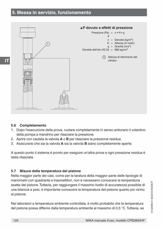
120 WIKA manuale d'uso, modello CPB3800HP
IT
1413
2099
.01
06/2
016
EN/D
E/IT
5.6 Completamento1. Dopo l'esecuzione della prova, ruotare completamente in senso antiorario il volantino
della pompa a mandrino per rilasciare la pressione.2. Aprire con cautela la valvola A o B per rilasciare la pressione residua.3. Assicurarsi che sia la valvola A sia la valvola B siano completamente aperte.
A questo punto il sistema è pronto per eseguire un'altra prova e ogni pressione residua è stata rilasciata.
5.7 Misura della temperatura del pistoneNella maggior parte dei casi, come per la taratura della maggior parte delle tipologie di manometri con quadrante e trasmettitori, non è necessario conoscere la temperatura esatta del pistone. Tuttavia, per raggiungere il massimo livello di accuratezza possibile di una bilancia a pesi, è importante conoscere la temperatura del pistone quanto più vicino al pistone.
Nei laboratori a temperatura ambiente controllata, è molto probabile che la temperatura del pistone possa differire dalla temperatura ambiente al massimo di 0,5 °C. Tuttavia, se
1
▲P dovuto a effetti di pressionePressione (Pa) = σ • H • g
Ifσ = Densità (kg/m³)H = Altezza (in metri)g = Gravità (m/s²)
Densità dell'olio VG 22 = 885 kg/cm³
Altezza di riferimento del cilindro
5. Messa in servizio, funzionamento
121WIKA manuale d'uso, modello CPB3800HP
IT
1413
2099
.01
06/2
016
EN/D
E/IT
si lavora a temperature non controllate, la temperatura del gruppo pistone deve essere misurata.
Un possibile modo per farlo è quello di utilizzare un elemento sensore termistore a forma di disco, incollato alla superficie esterna del gruppo pistone. L'elemento sensore deve essere isolato dalla temperatura ambiente coprendolo con una striscia sottile di polistirolo o altro materiale isolante e quindi incollandolo al gruppo pistone. In alternativa, può essere utilizzato il CalibratorUnit modello CPU6000.
Può essere fornito uno strumento di misura adatto. Se richiesto, contattare DH-Budenberg/WIKA.
5.8 Pulizia degli strumenti di misuraQuesto processo di pulizia/sgrassaggio è adatto esclusivamente per la pulizia di strumenti di misura della pressione con molle Bourdon in bronzo fosforoso, rame-berillo, monel o acciaio inox a forma di “C”.
Si sconsiglia di sgrassare i manometri con molle Bourdon in acciaio, in quanto anche una minima quantità di ruggine può portare a un'inesattezza nella misura e a un guasto prematuro della molla.
Questo metodo di pulizia non è adatto per manometri con molle Bourdon a spirale. Non è adatto neppure per strumenti di misura che devono essere utilizzati con ossigeno, in quanto non si assicura una rimozione completa dell'olio. In questo caso, contattare DH-Budenberg/WIKA.
EquipaggiamentoE' composto da una siringa e da un ago speciale curvato di 90°.
Istruzioni:1. Riempire la siringa con solvente (detergente a freddo adatto)2. Con l'attacco dello strumento di misura rivolto verso l'alto, spingere l'ago nell'attacco e
inserirlo con cautela nel foro che porta al tubo.3. Iniettare il solvente. In teoria, il tubo dovrebbe essere pieno fino a metà.4. Scuotere lo strumento di misura in diverse posizioni in modo da agitare il solvente.5. Aspirare nuovamente il solvente nella siringa tenendo lo strumento di misura inclinato.6. Verificare che il solvente rimosso sia pulito e puro. Per essere certi di aver rimosso
tutto l'olio, ripetere il processo di pulizia fino a quando il solvente è pulito come quando inserito.
5. Messa in servizio, funzionamento
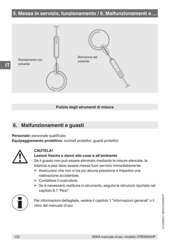
122 WIKA manuale d'uso, modello CPB3800HP
IT
1413
2099
.01
06/2
016
EN/D
E/IT
Pulizia degli strumenti di misura
Riempimento con solvente
Rimozione del solvente
5. Messa in servizio, funzionamento / 6. Malfunzionamenti e ...
6. Malfunzionamenti e guasti
Personale: personale qualificatoEquipaggiamento protettivo: occhiali protettivi, guanti protettivi
CAUTELA!Lesioni fisiche e danni alle cose e all'ambienteSe il guasto non può essere eliminato mediante le misure elencate, la bilancia a pesi deve essere messa fuori servizio immediatamente.
▶ Assicurarsi che non vi sia più alcuna pressione e impedire una riattivazione accidentale.
▶ Contattare il costruttore. ▶ Se è necessario restituire lo strumento, seguire le istruzioni riportate nel capitolo 8.1 “Resi”.
Per informazioni dettagliate, vedere il capitolo 1 “Informazioni generali” o il retro del manuale d'uso.
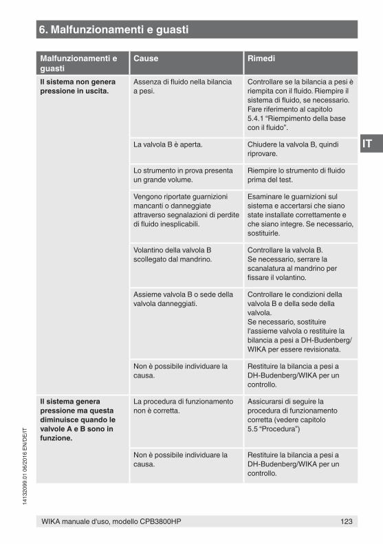
123WIKA manuale d'uso, modello CPB3800HP
IT
1413
2099
.01
06/2
016
EN/D
E/IT
Malfunzionamenti e guasti
Cause Rimedi
Il sistema non genera pressione in uscita.
Assenza di fluido nella bilancia a pesi.
Controllare se la bilancia a pesi è riempita con il fluido. Riempire il sistema di fluido, se necessario. Fare riferimento al capitolo 5.4.1 “Riempimento della base con il fluido”.
La valvola B è aperta. Chiudere la valvola B, quindi riprovare.
Lo strumento in prova presenta un grande volume.
Riempire lo strumento di fluido prima del test.
Vengono riportate guarnizioni mancanti o danneggiate attraverso segnalazioni di perdite di fluido inesplicabili.
Esaminare le guarnizioni sul sistema e accertarsi che siano state installate correttamente e che siano integre. Se necessario, sostituirle.
Volantino della valvola B scollegato dal mandrino.
Controllare la valvola B. Se necessario, serrare la scanalatura al mandrino per fissare il volantino.
Assieme valvola B o sede della valvola danneggiati.
Controllare le condizioni della valvola B e della sede della valvola.Se necessario, sostituire l'assieme valvola o restituire la bilancia a pesi a DH-Budenberg/WIKA per essere revisionata.
Non è possibile individuare la causa.
Restituire la bilancia a pesi a DH-Budenberg/WIKA per un controllo.
Il sistema genera pressione ma questa diminuisce quando le valvole A e B sono in funzione.
La procedura di funzionamento non è corretta.
Assicurarsi di seguire la procedura di funzionamento corretta (vedere capitolo 5.5 “Procedura”)
Non è possibile individuare la causa.
Restituire la bilancia a pesi a DH-Budenberg/WIKA per un controllo.
6. Malfunzionamenti e guasti
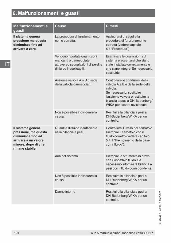
124 WIKA manuale d'uso, modello CPB3800HP
IT
1413
2099
.01
06/2
016
EN/D
E/IT
Malfunzionamenti e guasti
Cause Rimedi
Il sistema genera pressione ma questa diminuisce fino ad arrivare a zero.
La procedura di funzionamento non è corretta.
Assicurarsi di seguire la procedura di funzionamento corretta (vedere capitolo 5.5 “Procedura”)
Vengono riportate guarnizioni mancanti o danneggiate attraverso segnalazioni di perdite di fluido inesplicabili.
Esaminare le guarnizioni sul sistema e accertarsi che siano state installate correttamente e che siano integre. Se necessario, sostituirle.
Assieme valvola A o B o sede della valvola danneggiati.
Controllare le condizioni della valvola A e B e della sede della valvola.Se necessario, sostituire l'assieme valvola o restituire la bilancia a pesi a DH-Budenberg/WIKA per essere revisionata.
Non è possibile individuare la causa.
Restituire la bilancia a pesi a DH-Budenberg/WIKA per un controllo.
Il sistema genera pressione, ma questa diminuisce fino ad arrivare a un valore minore, dopo di che rimane stabile.
Quantità di fluido insufficiente nella bilancia a pesi.
Controllare il livello nel serbatoio. Riempire il serbatoio con il fluido corretto (vedere capitolo 5.4.1 “Riempimento della base con il fluido”).
Aria nel sistema. Riempire lo strumento in prova con il rispettivo fluido. Se necessario, rifornire la bilancia a pesi con il fluido corrispondente.
Non è possibile individuare la causa.
Restituire la bilancia a pesi a DH-Budenberg/WIKA per un controllo.
Danno interno Restituire la bilancia a pesi a DH-Budenberg/WIKA per un controllo.
6. Malfunzionamenti e guasti
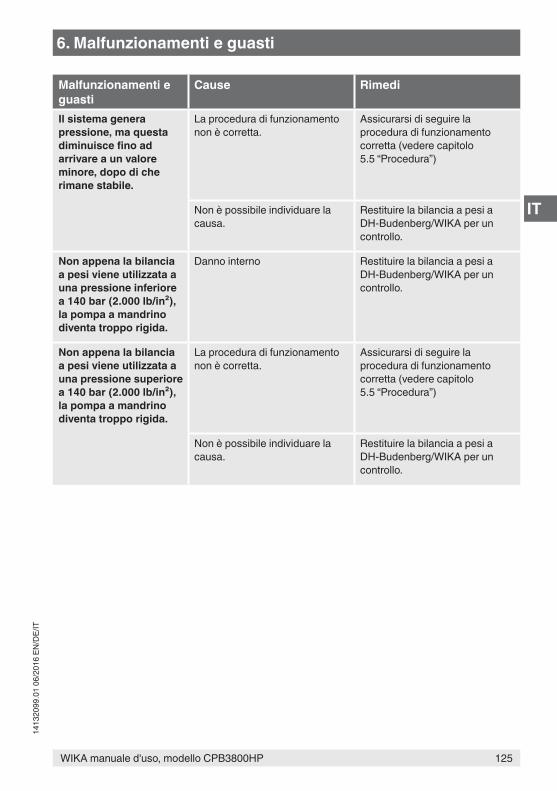
125WIKA manuale d'uso, modello CPB3800HP
IT
1413
2099
.01
06/2
016
EN/D
E/IT
Malfunzionamenti e guasti
Cause Rimedi
Il sistema genera pressione, ma questa diminuisce fino ad arrivare a un valore minore, dopo di che rimane stabile.
La procedura di funzionamento non è corretta.
Assicurarsi di seguire la procedura di funzionamento corretta (vedere capitolo 5.5 “Procedura”)
Non è possibile individuare la causa.
Restituire la bilancia a pesi a DH-Budenberg/WIKA per un controllo.
Non appena la bilancia a pesi viene utilizzata a una pressione inferiore a 140 bar (2.000 lb/in²), la pompa a mandrino diventa troppo rigida.
Danno interno Restituire la bilancia a pesi a DH-Budenberg/WIKA per un controllo.
Non appena la bilancia a pesi viene utilizzata a una pressione superiore a 140 bar (2.000 lb/in²), la pompa a mandrino diventa troppo rigida.
La procedura di funzionamento non è corretta.
Assicurarsi di seguire la procedura di funzionamento corretta (vedere capitolo 5.5 “Procedura”)
Non è possibile individuare la causa.
Restituire la bilancia a pesi a DH-Budenberg/WIKA per un controllo.
6. Malfunzionamenti e guasti
126 WIKA manuale d'uso, modello CPB3800HP
IT
1413
2099
.01
06/2
016
EN/D
E/IT
7. Manutenzione, pulizia e ricertificazione
Personale: personale qualificatoEquipaggiamento protettivo: occhiali protettivi, guanti protettivi
Per informazioni dettagliate, vedere il capitolo 1 “Informazioni generali” o il retro del manuale d'uso.
7.1 Manutenzione periodicaLe riparazioni devono essere effettuate solo dal costruttore.Utilizzare esclusivamente parti originali (vedere capitolo 10 “Accessori”).
L'unica manutenzione periodica necessaria è la pulizia delle unità e il controllo dei livelli del fluido. In caso di normale utilizzo, non è necessaria alcuna manutenzione ulteriore. Se necessario, il sistema può essere restituito al costruttore per essere ricondizionato. Ulteriori informazioni riguardo l'accuratezza di misura, la revisione e la ricertificazione sono disponibili anche al capitolo 7.4.1 “Revisione e ricertificazione delle bilance di pressione, manutenzione dell’accuratezza”.
I fluidi che potrebbero danneggiare l'ABS dovrebbero essere utilizzati con cautela. L'immersione continua della copertura in questi fluidi comporta danni. Eventuali fuoriuscite devono essere rimosse immediatamente.
7.2 Manutenzione correttiva7.2.1 Informazioni generaliDi seguito vengono fornite informazioni dettagliate riguardo allo smontaggio dell'unità e alla sostituzione delle parti di ricambio elencate (vedere capitolo 10 “Accessori”). Il numero identificativo dei componenti riportato tra parentesi in ogni procedura fa riferimento al disegno seguente.
7. Manutenzione, pulizia e ricertificazione
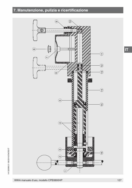
127WIKA manuale d'uso, modello CPB3800HP
IT
1413
2099
.01
06/2
016
EN/D
E/IT
8
7
65
43
2
1
9 10
1112
1314
1516
7. Manutenzione, pulizia e ricertificazione
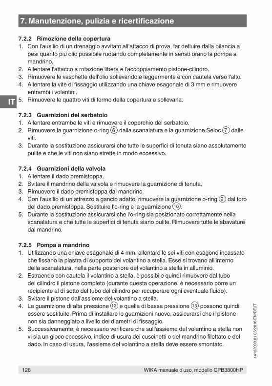
128 WIKA manuale d'uso, modello CPB3800HP
IT
1413
2099
.01
06/2
016
EN/D
E/IT
7.2.2 Rimozione della copertura1. Con l'ausilio di un drenaggio avvitato all'attacco di prova, far defluire dalla bilancia a
pesi quanto più olio possibile ruotando completamente in senso orario la pompa a mandrino.
2. Allentare l'attacco a rotazione libera e l'accoppiamento pistone-cilindro.3. Rimuovere le vaschette dell'olio sollevandole leggermente e con cautela verso l'alto.4. Allentare la vite di fissaggio utilizzando una chiave esagonale di 3 mm e rimuovere
entrambi i volantini.5. Rimuovere le quattro viti di fermo della copertura e sollevarla.
7.2.3 Guarnizioni del serbatoio1. Allentare entrambe le viti e rimuovere il coperchio del serbatoio.2. Rimuovere la guarnizione o-ring 6 dalla scanalatura e la guarnizione Seloc 7 dalle
viti.3. Durante la sostituzione assicurarsi che tutte le superfici di tenuta siano assolutamente
pulite e che le viti non siano strette in modo eccessivo.
7.2.4 Guarnizioni della valvola1. Allentare il dado premistoppa.2. Svitare il mandrino della valvola e rimuovere la guarnizione di tenuta.3. Rimuovere il dado premistoppa dal mandrino.4. Con l'ausilio di un attrezzo a gancio adatto, rimuovere la guarnizione o-ring 9 dal foro
del dado premistoppa. Sostituire l'o-ring e la guarnizione 10 .5. Durante la sostituzione assicurarsi che l'o-ring sia posizionato correttamente nella
scanalatura e che tutte le superfici di tenuta siano pulite. Rimuovere tutte le sbavature dal mandrino.
7.2.5 Pompa a mandrino1. Utilizzando una chiave esagonale di 4 mm, allentare le sei viti con esagono incassato
che fissano la piastra di supporto del volantino a stella. Esse si trovano all'interno della scanalatura, nella parte posteriore del volantino a stella in alluminio.
2. Estraendo con cautela il volantino a stella, è possibile quindi rimuovere dal tubo del cilindro il pistone completo (durante questa operazione, è necessario porre un recipiente al di sotto del tubo del cilindro per recuperare ogni eventuale fluido).
3. Svitare il pistone dall'assieme del volantino a stella.4. La guarnizione di alta pressione 12 e quella di bassa pressione 15 possono quindi
essere sostituite. Prima di installare le guarnizioni nuove, assicurarsi che il pistone non sia danneggiato a livello dei diametri di fissaggio.
5. Successivamente, è necessario verificare che sull'assieme del volantino a stella non vi sia un gioco eccessivo, indice di usura dei cuscinetti o del mandrino filettato e del dado. In caso di usura, l'assieme del volantino a stella deve essere smontato.
7. Manutenzione, pulizia e ricertificazione
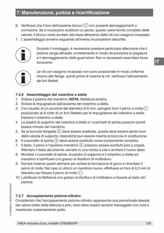
129WIKA manuale d'uso, modello CPB3800HP
IT
1413
2099
.01
06/2
016
EN/D
E/IT
6. Verificare che il foro dell'assieme blocco 11 non presenti danneggiamenti o corrosione. Se è necessario sostituire un pezzo, questo viene fornito completo delle valvole. Il blocco viene avvitato alla base attraverso delle viti con esagono incassato.
7. L'assemblaggio avviene seguendo all'inverso le procedure descritte.
Durante il montaggio, è necessario prestare particolare attenzione che il pistone venga allineato correttamente in modo da prevenire la piegatura e il danneggiamento delle guarnizioni. Non è necessario esercitare forza eccessiva.
Le viti con esagono incassato non sono posizionate in modo uniforme intorno alle flange, quindi prima di inserire le viti, verificare l'allineamento dei fori filettati.
7.2.6 Assemblaggio del volantino a stella1. Svitare il pistone dal mandrino. NOTA: filettatura sinistra.2. Svitare le impugnature dall'assieme del volantino a stella.3. Con l'ausilio di un punzone del diametro di 6 mm, spingere fuori il perno a molla 1
posizionato al di sotto di un foro filettato per le impugnature del volantino a stella. Estrarre il volantino a stella.
4. La piastra di supporto del volantino a stella e i cuscinetti di spinta possono quindi essere rimossi dal mandrino.
5. Se la boccola flangiata 2 deve essere sostituita, questa deve essere spinta fuori dalla valvola di supporto; dopodiché può essere inserita la boccola in sostituzione.
6. Il cuscinetto di spinta 3 deve essere sostituito come componente completo.7. Il dado, il perno e l'assieme mandrino 4 possono essere sostituiti solo a coppie.
Allentare il dado dal pistone, serrarlo in una morsa a vite e avvitare il nuovo dado.8. Montare il cuscinetto di spinta, la piastra di supporto e il volantino a stella sul
mandrino e lubrificare con grasso al disolfuro di molibdeno.9. Serrare insieme questi elementi per evitare la formazione di gioco e rimontare il
perno di molla. Nel caso si utilizzi un mandrino nuovo, effettuare un foro di 6,3 mm di diametro per fissare il perno di molla 1 .
10. Lubrificare la filettatura con grasso al disolfuro di molibdeno e fissarla al dado del pistone.
7.2.7 Accoppiamento pistone-cilindroConsiderato che l'accoppiamento pistone-cilindro rappresenta una percentuale elevata del valore totale della bilancia a pesi, esso deve essere sempre maneggiato con cura e mantenuto costantemente pulito.
7. Manutenzione, pulizia e ricertificazione
130 WIKA manuale d'uso, modello CPB3800HP
IT
1413
2099
.01
06/2
016
EN/D
E/IT
L'accoppiamento pistone-cilindro viene realizzato con valori di accuratezza di estrema precisione e pertanto si sconsiglia di smontarlo. Se è necessario pulirlo, i fori del pistone e del cilindro devono essere oliati immediatamente, in modo da proteggere la rifinitura di alta qualità.
Nel caso in cui l'unità dovesse danneggiarsi, la stessa deve essere inviata completa.Le parti appartenenti a unità diverse non sono intercambiabili, visto che devono essere pesate e valutate come un insieme.
Il numero di serie dell'accoppiamento pistone-cilindro figura nel certificato di taratura ed è contrassegnato sul corpo principale dell'unità. Questo numero, così come il numero di serie della bilancia a pesi, deve essere sempre indicato in corrispondenza dell'accoppiamento pistone-cilindro.
Gli attacchi dell'accoppiamento pistone-cilindro devono essere sempre chiusi con dei tappi quando l'accoppiamento viene rimosso dalla bilancia a pesi. Se, per qualsiasi ragione, l'accoppiamento viene rimosso, questo deve essere capovolto e riposto nel portamasse.
Questo consente la manipolazione dell'unità per facilitare le operazioni di riparazione e di sostituzione delle parti di ricambio.
7.3 Pulizia
CAUTELA!Lesioni fisiche e danni alle cose e all'ambienteUna pulizia impropria può provocare lesioni fisiche e danni alle cose e all'ambiente. I residui dei fluidi di processo negli strumenti smontati possono causare rischi alle persone, all'ambiente ed alla strumentazione.
▶ Effettuare la pulizia come descritto di seguito.
1. Prima della pulizia, scollegare correttamente lo strumento dall'alimentazione di pressione.
2. Utilizzare i dispositivi di protezione necessari.3. Pulire lo strumento con un panno umido.
CAUTELA!Danni alle coseUna pulizia impropria può causare danni allo strumento!
▶ Non usare detergenti aggressivi. ▶ Per la pulizia non utilizzare oggetti appuntiti o duri.
7. Manutenzione, pulizia e ricertificazione
131WIKA manuale d'uso, modello CPB3800HP
IT
1413
2099
.01
06/2
016
EN/D
E/IT
4. Lavare o pulire lo strumento smontato in prova, allo scopo di proteggere le persone e l'ambiente dall'esposizione con i fluidi residui.
Pulizia dell'unità e controllo dei livelli del fluidoUso con olioMantenere il sistema pulito anche dall'eventuale olio fuoriuscito. Ripulire le coppe di olio al di sotto degli attacchi di prova. Non utilizzare detergenti contenenti solventi in quanto potrebbero danneggiare le guarnizioni.
Assicurarsi che il serbatoio contenga una quantità di fluido sufficiente per eseguire le operazioni di taratura richieste. Se necessario, riempire il serbatoio con lo stesso fluido che è già stato usato. Non utilizzare altri tipi o marchi di fluido.
Se l'olio nella bilancia a pesi si sporca, utilizzare la pompa a mandrino per flussare l'olio pulito attraverso lo strumento con uno scarico avvitato all'attacco di prova (può essere utilizzato un attacco angolare). Prima dell'avvio, la pompa a mandrino deve essere completamente ruotata in senso orario.
Per informazioni sul reso dello strumento, fare riferimento al capitolo 8.1 “Resi”.
7.4 Ricertificazione
Certificato DKD/DAkkS/ACCREDIA - certificati emessi da enti ufficiali:Raccomandiamo una regolare taratura dello strumento da parte del produttore con intervalli di circa 5 anni. Le impostazioni base saranno corrette se necessario.
7.4.1 Revisione e ricertificazione delle bilance di pressione, manutenzione dell'accuratezza
L'accuratezza di una bilancia a pesi dipende soprattutto dall'area effettiva del gruppo pistone e dalle masse applicate al pistone. L'area effettiva del pistone può essere alterata dall'usura dell'unità. Questa è dovuta generalmente alla contaminazione dell'olio nella bilancia a pesi, causata da sostanze estranee provenienti dagli strumenti di misura da tarare come acqua, sostanze chimiche o dalla corrosione causata da sostanze inquinanti.
Le masse sono in acciaio inox austenitico, un materiale molto stabile. Esse devono essere pulite periodicamente utilizzando un metodo non abrasivo per rimuovere le impurità.
7. Manutenzione, pulizia e ricertificazione
132 WIKA manuale d'uso, modello CPB3800HP
IT
1413
2099
.01
06/2
016
EN/D
E/IT
7.4.2 Necessità di revisione e ricertificazioneRaccomandiamo una revisione e ritaratura della bilancia a pesi in qualsiasi momento nei casi seguenti:
■ Il pistone non può ruotare liberamente. ■ La discesa del pistone avviene a un tasso notevolmente maggiore rispetto a quando
era nuovo, rendendo difficile l'utilizzo della bilancia a pesi. ■ Le masse sono danneggiate. ■ La bilancia a pesi non può funzionare correttamente per via della presenza di usura e
di danneggiamenti alle tubature della pompa o alle valvole, non eliminabili dall'utente.
Questa bilancia a pesi può essere utilizzata per la taratura di strumenti di misura con un livello di accuratezza previsto di 1, 0,5 o 0,25 %. Le bilance a pesi non necessitano di essere inviate di frequente al costruttore per la revisione e la ricertficazione e, ammesso che vengano utilizzate correttamente, rimangono affidabili per molti anni. A queste condizioni è sufficiente effettuare una revisione ogni cinque anni.
Nel caso siano richieste prestazioni molto elevate in termini di accuratezza della bilancia a pesi, questa necessita di essere restituita per la revisione e la ricertificazione più frequentemente. Il periodo effettivo dipende da quanto viene utilizzata la bilancia a pesi. Ad esempio, una bilancia a pesi tenuta in un laboratorio e utilizzata correttamente potrebbe necessitare di essere inviata per le sopra indicate attività ogni due o cinque anni. Per una bilancia a pesi che viene spesso spostata di sito in sito e che viene utilizzata per la taratura di strumenti di misura ad alta precisione o di trasmettitori per impianti di processo industriali o per la misurazione di pressione direttamente nel processo, potrebbe essere necessario restituirla a intervalli minori di quelli sopra indicati.
L'intervallo effettivo tra la revisione e la ricertificazione deve essere stabilito dall'utente alla luce delle osservazioni fatte sopra, tenendo conto anche dei requisiti delle autorità di controllo responsabili a riguardo.
7.4.3 Identificazione delle masseTutte le masse fornite insieme a una bilancia a pesi vengono assegnate a un numero di set di masse e ne riportano il numero corrispondente. Inoltre, se si vuole assicurare che soltanto delle masse specifiche vengano utilizzate con una singola bilancia a pesi, pistone o accoppiamento pistone-cilindro, deve essere riportato anche il numero di serie della bilancia a pesi, del pistone o dell'accoppiamento pistone-cilindro sulle masse principali. Tuttavia, a causa delle dimensioni ridotte di certe masse, potrebbe non essere possibile riportare tutte le informazioni indicate sopra.
7. Manutenzione, pulizia e ricertificazione
133WIKA manuale d'uso, modello CPB3800HP
IT
1413
2099
.01
06/2
016
EN/D
E/IT
7.4.4 Revisione e ricertificazionePer garantire il miglior servizio di assistenza, la bilancia a pesi deve essere restituita come unità completa, comprensiva della base, dell'accoppiamento pistone-cilindro e di tutte le masse.Anche la base stessa può essere soggetta a manutenzione. L'accoppiamento pistone-cilindro con le masse deve essere comunque restituito per la revisione. In questi casi, la certificazione rilasciata dopo la revisione si riferisce soltanto all'accoppiamento pistone-cilindro e al numero dei set di masse, ma non alla base alla quale erano originariamente installati.
Le basi della bilancia a pesi vengono smontate, le tubature pulite, le guarnizioni sostituite e, se richiesto, i componenti usurati sostituiti; quindi tutte le parti vengono rimontate e sottoposte a test.
Tutte le masse vengono controllate e, se possibile, riportate ai loro limiti originari. Se mancano una o due masse o se una riparazione non è più conveniente da un punto di vista economico, esse vengono sostituite. Nel caso in cui più di due masse siano mancanti/non siano più convenienti da riparare, verranno richieste istruzioni da parte del cliente.
Viene verificata l'accuratezza e la sensibilità del gruppo pistone. Se questa, per qualsiasi ragione, non dovesse essere soddisfacente, viene inviato al cliente un preventivo per uno strumento sostitutivo.
Per ogni bilancia a pesi revisionata viene rilasciato un nuovo certificato dell'accuratezza. Salvo diversamente specificato nell'ordine, nel caso in cui ci sia stato un leggero cambiamento dell'area effettiva del pistone, questo viene riportato nel certificato; l'accuratezza di misura si modificherà per un massimo dello 0,03 %.
Ad esempio, il certificato di accuratezza di una bilancia a pesi revisionata potrebbe indicare che l'errore non ammonta a più dello 0,05 %, mentre nel certificato originale si riporta che l'errore non supera lo 0,02 %.
Per un sistema revisionato può essere rilasciato un certificato di taratura UKAS o DKD/DAkkS. Informazioni più dettagliate a riguardo sono disponibili su richiesta.
7. Manutenzione, pulizia e ricertificazione
134 WIKA manuale d'uso, modello CPB3800HP
IT
1413
2099
.01
06/2
016
EN/D
E/IT
8. Resi e smaltimento
Personale: personale qualificatoEquipaggiamento protettivo: occhiali protettivi, guanti protettivi
ATTENZIONE!Lesioni fisiche e danni alle cose e all'ambiente a causa di fluidi residuiFluidi residui presenti all'interno della bilancia a pesi possono causare rischi a persone, all'ambiente e allo strumento stesso.
▶ Indossare l'equipaggiamento di protezione necessario (vedere capitolo 2.5 “Dispositivi di protezione personale”).
▶ Osservare le informazioni contenute nella scheda di sicurezza per il corrispondente fluido.
▶ Lavare o pulire lo strumento smontato, allo scopo di proteggere le persone e l'ambiente dall'esposizione con i fluidi residui.
8.1 Resi
Osservare attentamente lo seguenti indicazioni per la spedizione dello strumento:Tutti gli strumenti inviati a DH-Budenberg/WIKA devono essere privi di qualsiasi tipo di sostanze pericolose (acidi, basi, soluzioni, ecc.) e pertanto devono essere puliti prima di essere restituiti.
ATTENZIONE!Lesioni fisiche e danni alle cose e all'ambiente a causa di fluidi residuiFluidi residui presenti all'interno della bilancia a pesi possono causare rischi a persone, all'ambiente e allo strumento stesso.
▶ In caso di sostanze pericolose, è inclusa la scheda di sicurezza del materiale per il fluido corrispondente.
▶ Pulire lo strumento, vedere capitolo 7.3 “Pulizia”.
In caso di restituzione dello strumento, utilizzare l'imballo originale o utilizzare un contenitore di trasporto adeguato.
Per evitare danni:1. Posizionare l'accoppiamento pistone-cilindro nell'imballaggio di trasporto previsto
(vedere capitolo 5.4 “Montaggio della bilancia a pesi”).2. Riporre lo strumento nella scatola con materiale assorbente gli urti. Posizionare
materiale per assorbire gli urti su tutti i lati all'interno dell'imballo.
8. Resi e smaltimento
135WIKA manuale d'uso, modello CPB3800HP
IT
1413
2099
.01
06/2
016
EN/D
E/IT
3. Se possibile, includere una bustina di gel anti-umidità all’interno dell’imballo.4. Etichettare la spedizione come trasporto di uno strumento altamente sensibile.
Le informazioni sulle modalità di gestione resi sono disponibili nella sezione “Servizi” del nostro sito web.
8.2 SmaltimentoLo smaltimento inappropriato può provocare rischi per l'ambiente.Lo smaltimento dei componenti dello strumento e dei materiali di imballaggio deve essere effettuato in modo compatibile ed in accordo alle normative nazionali.
8. Resi e smaltimento
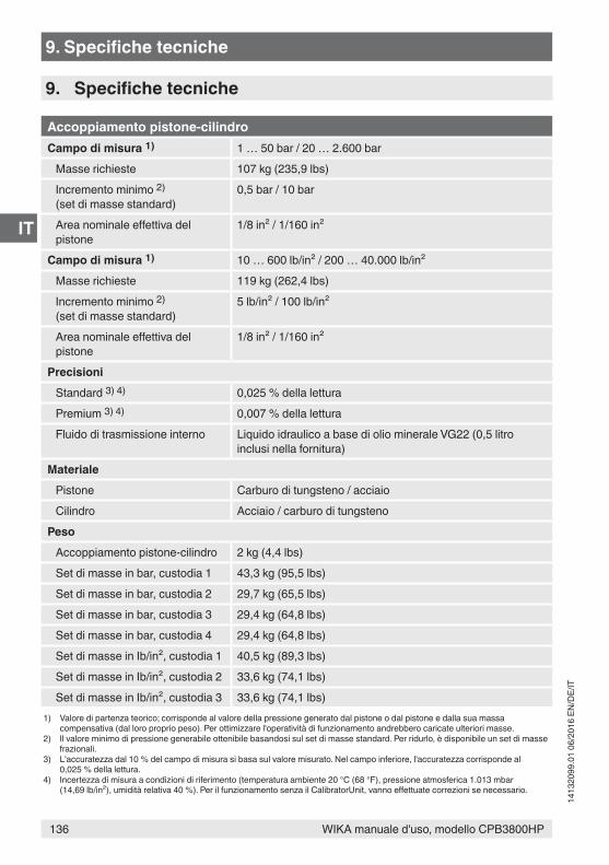
136 WIKA manuale d'uso, modello CPB3800HP
IT
1413
2099
.01
06/2
016
EN/D
E/IT
9. Specifiche tecniche
Accoppiamento pistone-cilindroCampo di misura 1) 1 … 50 bar / 20 … 2.600 bar
Masse richieste 107 kg (235,9 lbs)Incremento minimo 2) (set di masse standard)
0,5 bar / 10 bar
Area nominale effettiva del pistone
1/8 in² / 1/160 in²
Campo di misura 1) 10 … 600 lb/in² / 200 … 40.000 lb/in²Masse richieste 119 kg (262,4 lbs)Incremento minimo 2) (set di masse standard)
5 lb/in² / 100 lb/in²
Area nominale effettiva del pistone
1/8 in² / 1/160 in²
PrecisioniStandard 3) 4) 0,025 % della letturaPremium 3) 4) 0,007 % della letturaFluido di trasmissione interno Liquido idraulico a base di olio minerale VG22 (0,5 litro
inclusi nella fornitura)Materiale
Pistone Carburo di tungsteno / acciaioCilindro Acciaio / carburo di tungsteno
PesoAccoppiamento pistone-cilindro 2 kg (4,4 lbs)Set di masse in bar, custodia 1 43,3 kg (95,5 lbs)Set di masse in bar, custodia 2 29,7 kg (65,5 lbs)Set di masse in bar, custodia 3 29,4 kg (64,8 lbs)Set di masse in bar, custodia 4 29,4 kg (64,8 lbs)Set di masse in Ib/in², custodia 1 40,5 kg (89,3 lbs)Set di masse in Ib/in², custodia 2 33,6 kg (74,1 lbs)Set di masse in Ib/in², custodia 3 33,6 kg (74,1 lbs)
1) Valore di partenza teorico; corrisponde al valore della pressione generato dal pistone o dal pistone e dalla sua massa compensativa (dal loro proprio peso). Per ottimizzare l'operatività di funzionamento andrebbero caricate ulteriori masse.
2) Il valore minimo di pressione generabile ottenibile basandosi sul set di masse standard. Per ridurlo, è disponibile un set di masse frazionali.
3) L'accuratezza dal 10 % del campo di misura si basa sul valore misurato. Nel campo inferiore, l'accuratezza corrisponde al 0,025 % della lettura.
4) Incertezza di misura a condizioni di riferimento (temperatura ambiente 20 °C (68 °F), pressione atmosferica 1.013 mbar (14,69 lb/in²), umidità relativa 40 %). Per il funzionamento senza il CalibratorUnit, vanno effettuate correzioni se necessario.
9. Specifiche tecniche
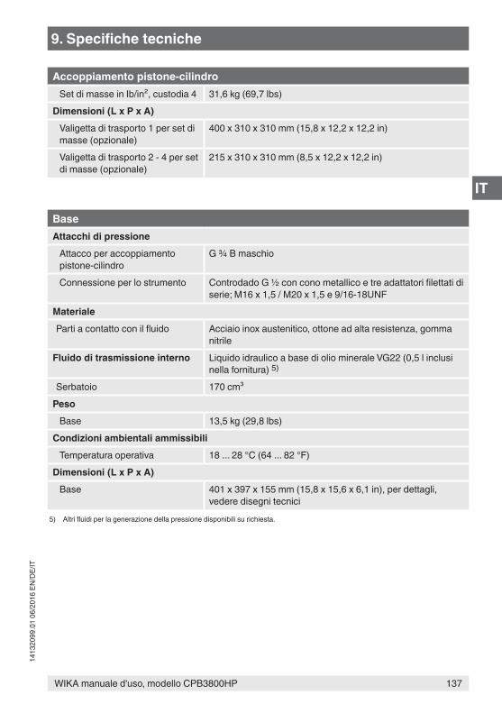
137WIKA manuale d'uso, modello CPB3800HP
IT
1413
2099
.01
06/2
016
EN/D
E/IT
Accoppiamento pistone-cilindroSet di masse in Ib/in², custodia 4 31,6 kg (69,7 lbs)
Dimensioni (L x P x A)Valigetta di trasporto 1 per set di masse (opzionale)
400 x 310 x 310 mm (15,8 x 12,2 x 12,2 in)
Valigetta di trasporto 2 - 4 per set di masse (opzionale)
215 x 310 x 310 mm (8,5 x 12,2 x 12,2 in)
BaseAttacchi di pressione
Attacco per accoppiamento pistone-cilindro
G ¾ B maschio
Connessione per lo strumento Controdado G ½ con cono metallico e tre adattatori filettati di serie; M16 x 1,5 / M20 x 1,5 e 9/16-18UNF
MaterialeParti a contatto con il fluido Acciaio inox austenitico, ottone ad alta resistenza, gomma
nitrileFluido di trasmissione interno Liquido idraulico a base di olio minerale VG22 (0,5 l inclusi
nella fornitura) 5)
Serbatoio 170 cm³Peso
Base 13,5 kg (29,8 lbs)Condizioni ambientali ammissibili
Temperatura operativa 18 ... 28 °C (64 ... 82 °F)Dimensioni (L x P x A)
Base 401 x 397 x 155 mm (15,8 x 15,6 x 6,1 in), per dettagli, vedere disegni tecnici
5) Altri fluidi per la generazione della pressione disponibili su richiesta.
9. Specifiche tecniche
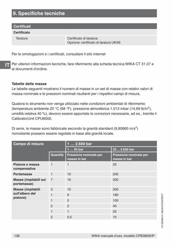
138 WIKA manuale d'uso, modello CPB3800HP
IT
1413
2099
.01
06/2
016
EN/D
E/IT
CertificatiCertificato
Taratura Certificato di taraturaOpzione: certificato di taratura UKAS
Per le omologazioni e i certificati, consultare il sito internet
Per ulteriori informazioni tecniche, fare riferimento alla scheda tecnica WIKA CT 31.07 e ai documenti d'ordine.
Tabelle delle masseLe tabelle seguenti mostrano il numero di masse in un set di masse con relativi valori di massa nominale e le pressioni nominali risultanti per i rispettivi campi di misura.
Qualora lo strumento non venga utilizzato nelle condizioni ambientali di riferimento (temperatura ambiente 20 °C (68 °F), pressione atmosferica 1.013 mbar (14,69 lb/in²), umidità relativa 40 %), devono essere apportate le correzioni necessarie, ad es., tramite il CalibratorUnit CPU6000.
Di serie, le masse sono fabbricate secondo la gravità standard (9,80665 m/s²) nonostante possano essere regolate in base alla gravità locale.
Campo di misura 1 … 2.600 bar1 … 50 bar 20 ... 2.600 bar
Quantità Pressione nominale per massa in bar
Pressione nominale per massa in bar
Pistone e massa compensativa
1 1 20
Portamasse 1 10 200Masse (impilabili sul portamasse)
7 10 200
Masse (impilabili sull'albero del pistone)
3 10 2001 9 1801 5 1002 2 401 1 202 0,5 10
9. Specifiche tecniche
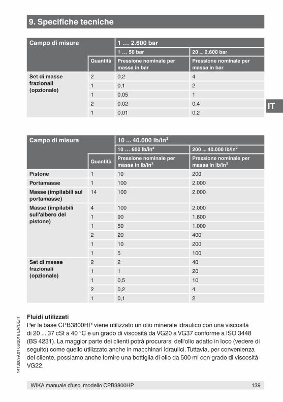
139WIKA manuale d'uso, modello CPB3800HP
IT
1413
2099
.01
06/2
016
EN/D
E/IT
Campo di misura 1 … 2.600 bar1 … 50 bar 20 ... 2.600 bar
Quantità Pressione nominale per massa in bar
Pressione nominale per massa in bar
Set di masse frazionali(opzionale)
2 0,2 41 0,1 21 0,05 12 0,02 0,41 0,01 0,2
Campo di misura 10 ... 40.000 lb/in²10 … 600 lb/in² 200 ... 40.000 lb/in²
Quantità Pressione nominale per massa in lb/in²
Pressione nominale per massa in lb/in²
Pistone 1 10 200Portamasse 1 100 2.000Masse (impilabili sul portamasse)
14 100 2.000
Masse (impilabili sull'albero del pistone)
4 100 2.0001 90 1.8001 50 1.0002 20 4001 10 2001 5 100
Set di masse frazionali(opzionale)
2 2 401 1 201 0,5 102 0,2 41 0,1 2
Fluidi utilizzatiPer la base CPB3800HP viene utilizzato un olio minerale idraulico con una viscosità di 20 ... 37 cSt a 40 °C e un grado di viscosità da VG20 a VG37 conforme a ISO 3448 (BS 4231). La maggior parte dei clienti potrà procurarsi dell'olio adatto in loco (vedere di seguito) come quello utilizzato anche in macchinari idraulici. Tuttavia, per convenienza del cliente, possiamo anche fornire una bottiglia di olio da 500 ml con grado di viscosità VG22.
9. Specifiche tecniche
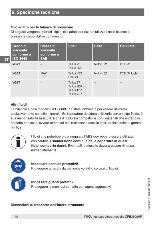
140 WIKA manuale d'uso, modello CPB3800HP
IT
1413
2099
.01
06/2
016
EN/D
E/IT
Olio adatto per le bilance di pressioneDi seguito vengono riportati i tipi di olio adatti per essere utilizzati nelle bilance di pressione disponibili in commercio.
Grado di viscosità conforme a ISO 3448
Classe di viscosità conforme a SAE
Shell Esso Cellulare
VG22 -- Tellus 22Tellus R22
Nuto H22 DTE 22
VG32 10W Tellus V32DTE 24
Nuto H32 DTE Oil Light
VG37 -- Tellus 37Tellus R37Tellus T37Tellus V37
-- --
Altri fluidiLa bilancia a pesi modello CPB3800HP è stata fabbricata per essere utilizzata esclusivamente con olio minerale. Se l'operatore desidera utilizzarla con un altro fluido, è sua responsabilità assicurarsi che il fluido sia compatibile con i materiali che entrano in contatto con esso, ovvero ottone ad alta resistenza, acciaio inox, acciaio dolce e gomma nitrilica.
I fluidi che potrebbero danneggiare l'ABS dovrebbero essere utilizzati con cautela. L'immersione continua della copertura in questi fluidi comporta danni. Eventuali fuoriuscite devono essere rimosse immediatamente.
Indossare occhiali protettivi!Proteggere gli occhi da particelle volatili o spruzzi di liquidi.
Indossare guanti protettivi!Proteggere le mani dal contatto con agenti aggressivi.
Dimensioni di trasporto dell'intero strumento
9. Specifiche tecniche
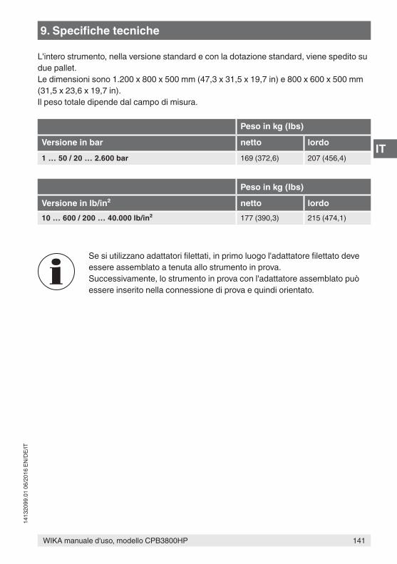
141WIKA manuale d'uso, modello CPB3800HP
IT
1413
2099
.01
06/2
016
EN/D
E/IT
L'intero strumento, nella versione standard e con la dotazione standard, viene spedito su due pallet.Le dimensioni sono 1.200 x 800 x 500 mm (47,3 x 31,5 x 19,7 in) e 800 x 600 x 500 mm (31,5 x 23,6 x 19,7 in).Il peso totale dipende dal campo di misura.
Peso in kg (lbs)
Versione in bar netto lordo
1 … 50 / 20 … 2.600 bar 169 (372,6) 207 (456,4)
Peso in kg (lbs)
Versione in lb/in² netto lordo10 … 600 / 200 … 40.000 lb/in² 177 (390,3) 215 (474,1)
Se si utilizzano adattatori filettati, in primo luogo l'adattatore filettato deve essere assemblato a tenuta allo strumento in prova.Successivamente, lo strumento in prova con l'adattatore assemblato può essere inserito nella connessione di prova e quindi orientato.
9. Specifiche tecniche
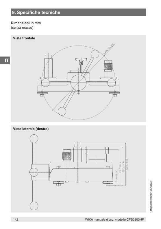
142 WIKA manuale d'uso, modello CPB3800HP
IT
1413
2099
.01
06/2
016
EN/D
E/IT
Dimensioni in mm(senza masse)
Vista laterale (destra)
Vista frontale
9. Specifiche tecniche
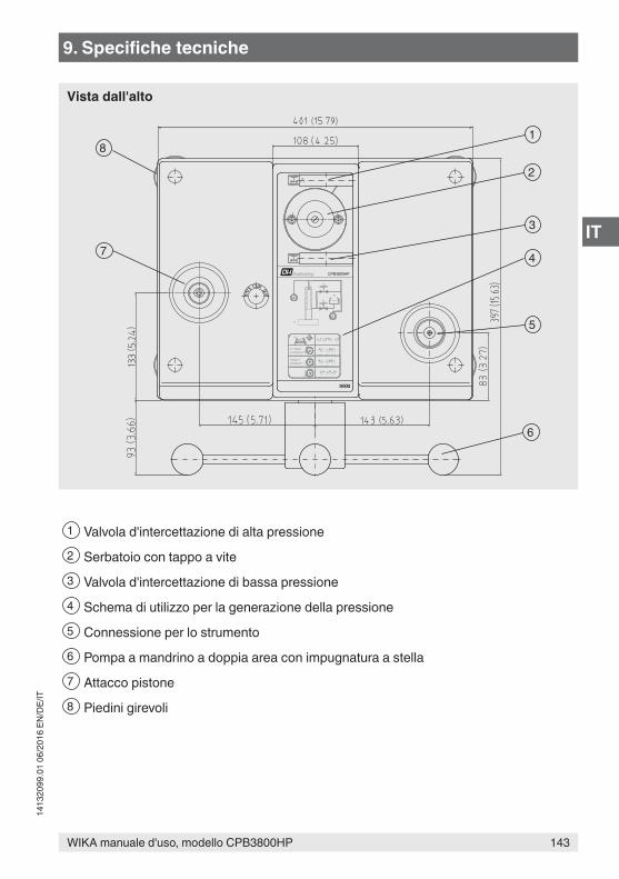
143WIKA manuale d'uso, modello CPB3800HP
IT
1413
2099
.01
06/2
016
EN/D
E/IT
A
140bar +2000lb/in² +
0
0-140bar0-2000lb/in²
R
BA P
AP B
AB P
A B P P
P
B
A
R
CPB3800HP
8
7
1
2
3
4
5
6
1 Valvola d'intercettazione di alta pressione2 Serbatoio con tappo a vite3 Valvola d'intercettazione di bassa pressione4 Schema di utilizzo per la generazione della pressione5 Connessione per lo strumento6 Pompa a mandrino a doppia area con impugnatura a stella7 Attacco pistone8 Piedini girevoli
Vista dall'alto
9. Specifiche tecniche
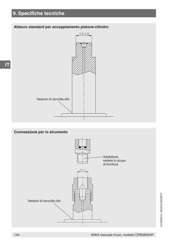
144 WIKA manuale d'uso, modello CPB3800HP
IT
1413
2099
.01
06/2
016
EN/D
E/IT
Vassoio di raccolta olio
Vassoio di raccolta olio
Adattatore, vedere lo scopo di fornitura
Attacco standard per accoppiamento pistone-cilindro
Connessione per lo strumento
9. Specifiche tecniche
145WIKA manuale d'uso, modello CPB3800HP
IT
1413
2099
.01
06/2
016
EN/D
E/IT
10. AccessoriVersioni strumento
■ Varie unità di pressione ■ Sistemi con accuratezza aumentata allo 0,007 %
Taratura ■ Certificato di taratura UKAS (taratura di pressione con un set di masse) ■ Certificato di taratura UKAS (taratura della pressione con un accoppiamento pistone-
cilindro) ■ Certificato di taratura UKAS (taratura di area e massa) ■ Certificato di taratura UKAS (taratura di massa)
Adattatore ■ Adattatore per porta di connessione, filettatura maschio M16 x 1,5 con cono di tenuta,
mat.: acciaio inox temprato ■ Adattatore per porta di connessione, filettatura maschio M20 x 1,5 con cono di tenuta,
mat.: acciaio inox temprato ■ Adattatore per porta di connessione, filettatura maschio 9/16-18 UNF con cono di
tenuta, mat.: acciaio inox temprato ■ Adattatore per porta di connessione, filettatura femmina G ½ con O-ring, max.
1.600 bar, mat.: 1.4571
Set di masse e masse incrementali fini ■ Masse realizzate con il valore di gravità locale specificato ■ Set di masse incrementali fini in bar ■ Set di masse incrementali fini in lb/in²
Liquidi ■ Fluido idraulico a base di olio minerale VG22 in bottiglia di plastica, contenuto 0,5 litri ■ Altri fluidi di trasmissione della pressione
Stoccaggio ■ Custodia di stoccaggio per la base dello strumento (e l'accoppiamento pistone-cilindro
CPB3800HP) ■ Quattro custodie di legno per il set di masse ■ Valigetta di stoccaggio per base, set di masse e accoppiamento pistone-cilindro
Accessori ■ Set di guarnizioni e di manutenzione per la base dello strumento ■ Set di attrezzi composto da chiave doppia fissa, guarnizioni di ricambio, attrezzo di
rimozione e di reinserimento dell'indice.
10. Accessori

146 WIKA manuale d'uso, modello CPB3800HP
IT
1413
2099
.01
06/2
016
EN/D
E/IT
147WIKA manuale d'uso, modello CPB3800HP
IT
1413
2099
.01
06/2
016
EN/D
E/IT

148 WIKA operating instructions, model CPB3800HP
1413
2099
.01
06/2
016
EN/D
E/IT
WIKA Alexander Wiegand SE & Co. KGAAlexander-Wiegand-Straße 3063911 Klingenberg • GermanyTel. +49 9372 132-0Fax +49 9372 [email protected]
WIKA subsidiaries worldwide can be found online at www.wika.com.WIKA-Niederlassungen weltweit finden Sie online unter www.wika.de.Per le filiali WIKA nel mondo, visitate il nostro sito www.wika.it.