Embed Size (px)
Citation preview

Operating Instructions and Parts Manual Box and Pan Brakes Models BPF-1240 and BPF-1450
WALTER MEIER (Manufacturing) Inc.
427 New Sanford Road LaVergne, Tennessee 37086 Part No. M-752125 Ph.: 800-274-6848 Revision A 09/2011 www.waltermeier.com Copyright © 2011 Walter Meier (Manufacturing) Inc.
2
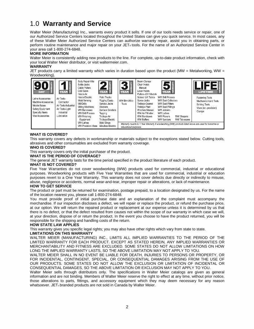
1.0 Warranty and Service Walter Meier (Manufacturing) Inc., warrants every product it sells. If one of our tools needs service or repair, one of our Authorized Service Centers located throughout the United States can give you quick service. In most cases, any of these Walter Meier Authorized Service Centers can authorize warranty repair, assist you in obtaining parts, or perform routine maintenance and major repair on your JET® tools. For the name of an Authorized Service Center in your area call 1-800-274-6848. MORE INFORMATION Walter Meier is consistently adding new products to the line. For complete, up-to-date product information, check with your local Walter Meier distributor, or visit waltermeier.com. WARRANTY JET products carry a limited warranty which varies in duration based upon the product (MW = Metalworking, WW = Woodworking).
WHAT IS COVERED? This warranty covers any defects in workmanship or materials subject to the exceptions stated below. Cutting tools, abrasives and other consumables are excluded from warranty coverage. WHO IS COVERED? This warranty covers only the initial purchaser of the product. WHAT IS THE PERIOD OF COVERAGE? The general JET warranty lasts for the time period specified in the product literature of each product. WHAT IS NOT COVERED? Five Year Warranties do not cover woodworking (WW) products used for commercial, industrial or educational purposes. Woodworking products with Five Year Warranties that are used for commercial, industrial or education purposes revert to a One Year Warranty. This warranty does not cover defects due directly or indirectly to misuse, abuse, negligence or accidents, normal wear-and-tear, improper repair or alterations, or lack of maintenance. HOW TO GET SERVICE The product or part must be returned for examination, postage prepaid, to a location designated by us. For the name of the location nearest you, please call 1-800-274-6848. You must provide proof of initial purchase date and an explanation of the complaint must accompany the merchandise. If our inspection discloses a defect, we will repair or replace the product, or refund the purchase price, at our option. We will return the repaired product or replacement at our expense unless it is determined by us that there is no defect, or that the defect resulted from causes not within the scope of our warranty in which case we will, at your direction, dispose of or return the product. In the event you choose to have the product returned, you will be responsible for the shipping and handling costs of the return. HOW STATE LAW APPLIES This warranty gives you specific legal rights; you may also have other rights which vary from state to state. LIMITATIONS ON THIS WARRANTY WALTER MEIER (MANUFACTURING) INC., LIMITS ALL IMPLIED WARRANTIES TO THE PERIOD OF THE LIMITED WARRANTY FOR EACH PRODUCT. EXCEPT AS STATED HEREIN, ANY IMPLIED WARRANTIES OR MERCHANTABILITY AND FITNESS ARE EXCLUDED. SOME STATES DO NOT ALLOW LIMITATIONS ON HOW LONG THE IMPLIED WARRANTY LASTS, SO THE ABOVE LIMITATION MAY NOT APPLY TO YOU. WALTER MEIER SHALL IN NO EVENT BE LIABLE FOR DEATH, INJURIES TO PERSONS OR PROPERTY, OR FOR INCIDENTAL, CONTINGENT, SPECIAL, OR CONSEQUENTIAL DAMAGES ARISING FROM THE USE OF OUR PRODUCTS. SOME STATES DO NOT ALLOW THE EXCLUSION OR LIMITATION OF INCIDENTAL OR CONSEQUENTIAL DAMAGES, SO THE ABOVE LIMITATION OR EXCLUSION MAY NOT APPLY TO YOU. Walter Meier sells through distributors only. The specifications in Walter Meier catalogs are given as general information and are not binding. Members of Walter Meier reserve the right to effect at any time, without prior notice, those alterations to parts, fittings, and accessory equipment which they may deem necessary for any reason whatsoever. JET® branded products are not sold in Canada by Walter Meier.

3
2.0 Table of Contents Section Page 1.0 Warranty and Service ....................................................................................................................... 2 2.0 Table of Contents ............................................................................................................................. 3 3.0 Safety Warnings ............................................................................................................................... 4 4.0 About this manual ............................................................................................................................. 5 5.0 Features ........................................................................................................................................... 5 6.0 Specifications ................................................................................................................................... 6 7.0 Set-Up and Assembly ....................................................................................................................... 6
7.1 Floor Diagram ............................................................................................................................... 6 7.2 Unpacking and cleanup ................................................................................................................. 7 7.3 Assembly ...................................................................................................................................... 7
8.0 Operation.......................................................................................................................................... 7 8.1 Adjusting setback .......................................................................................................................... 7 8.2 Adjusting clamping pressure .......................................................................................................... 7 8.3 Repeat bends ................................................................................................................................ 7 8.4 General procedure ........................................................................................................................ 8
9.0 Maintenance ..................................................................................................................................... 8 10.0 Troubleshooting .............................................................................................................................. 8 11.0 Replacement Parts ......................................................................................................................... 8
11.1.1 Box and Pan Brake (40” model) – Exploded View ..................................................................... 9 11.1.2 Box and Pan Brake (40” model) – Parts List............................................................................ 10 11.2.1 Box and Pan Brake (50” model) – Exploded View ................................................................... 11 11.2.2 Box and Pan Brake (50” model) – Parts List............................................................................ 12

4
3.0 Safety Warnings 1. Read and understand entire owner’s manual
before attempting assembly or operation.
2. Read and understand the warnings posted on the machine and in this manual. Failure to comply with all of these warnings may cause serious injury.
3. Replace warning labels if they become obscured or removed.
4. This box and pan brake is designed and intended for use by properly trained and experienced personnel only. If you are not familiar with the proper and safe operation of a brake, do not use until proper training and knowledge have been obtained.
5. Do not use this machine for other than its intended use. If used for other purposes, Walter Meier (Manufacturing), Inc., disclaims any real or implied warranty and holds itself harmless from any injury that may result from that use.
6. Do not exceed the rated capacity of the brake.
7. Always wear approved safety glasses/face shields while using this machine. Everyday eyeglasses only have impact resistant lenses; they are not safety glasses.
8. Before operating this brake, remove tie, rings, watches and other jewelry, and roll sleeves up past the elbows. Do not wear loose clothing, and confine long hair. Non-slip footwear or anti-skid floor strips are recommended.
9. Some dust created by power sanding, sawing, grinding, drilling and other construction activities contains chemicals known to cause cancer, birth defects or other reproductive harm. Some examples of these chemicals are:
• Lead from lead based paint. • Crystalline silica from bricks, cement and
other masonry products. • Arsenic and chromium from chemically
treated lumber.
Your risk of exposure varies, depending on how often you do this type of work. To reduce your exposure to these chemicals, work in a well-ventilated area and work with approved safety equipment, such as face or dust masks that are specifically designed to filter out microscopic particles.
10. Do not operate this machine while tired or under the influence of drugs, alcohol or any medication.
11. Remove adjusting keys and wrenches. Form a habit of checking to see that keys and adjusting wrenches are removed from the machine before using.
12. Sheet metal stock has sharp edges. Use leather gloves when handling.
13. Keep hands and fingers clear of area in front and rear of brake.
14. This box and pan brake should be secured to the floor to prevent tipping.
15. Keep safety guards in place at all times when the machine is in use. If removed for maintenance purposes, use extreme caution and replace the guards immediately after maintenance is complete.
16. Provide for adequate space surrounding work area and non-glare, overhead lighting.
17. Keep the floor around the machine clean and free of scrap material, oil and grease.
18. Keep visitors a safe distance from the work area. Keep children away.
19. Give your work undivided attention. Looking around, carrying on a conversation and “horse-play” are careless acts that can result in serious injury.
20. Maintain a balanced stance at all times so that you do not fall or lean against moving parts. Do not overreach or use excessive force to perform any machine operation.
21. Use the right tool at the correct speed and feed rate. Do not force a tool or attachment to do a job for which it was not designed. The right tool will do the job better and more safely.
22. Do not stand on machine. Serious injury could occur if machine tips over.
Familiarize yourself with the following safety notices used in this manual.
This means that if precautions are not heeded, it may result in minor injury and/or possible machine damage.
This means that if precautions are not heeded, it may result in serious or even fatal injury.

5
4.0 About this manual This manual is provided by Walter Meier (Manufacturing) Inc. covering the safe operation and maintenance procedures for a JET BPF-1240 and BPF-1450 Box and Pan Brake. This manual contains instructions on installation, safety precautions, general operating procedures, maintenance instructions and parts breakdown. Your machine has been designed and constructed to provide years of trouble-free operation if used in accordance with instructions set forth in this document.
This manual is not intended to be a guide to sheet metal bending, bend allowances, material choice, etc. Consult a Machinery’s Handbook and/or experienced users for such information. Whatever accepted methods or materials are used, always make personal safety a priority.
If there are questions or comments, please contact your local supplier or Walter Meier. Walter Meier can also be reached at our web site: www.waltermeier.com.
Retain this manual for future reference. If the machine transfers ownership, the manual should accompany it.
5.0 Features
Figure 1 1. Clamping leaf 2. Clamping fingers 3. Clamping adjustment knob (x2) 4. Stop bolt 5. Setback locking screw (x2) 6. Setback knob (x2) 7. Bending leaf blade
8. Bending leaf 9. Foot pedal for clamping 10. Foot pedal lock 11. Support leg (x2) 12. Crown adjustment rod 13. Air spring 14. Grease fitting (x2)

6
6.0 Specifications Model Number .......................................................................BPF-1240 .................................................... BPF-1450 Stock Number ............................................................................752125 ........................................................ 752127 Materials:
Frame ......................................................... welded steel plate/tubing ..............................welded steel plate/tubing Clamping fingers ................................... ground steel, ceramic coated ....................... ground steel, ceramic coated Clamping block/bending blade ..........................precision ground steel .................................. precision ground steel
Capacities: Bending length .............................................................40” (1020mm) .............................................. 50” (1270mm) Maximum thickness, mild steel ................................................. 12 ga. .......................................................... 14 ga. Maximum beam lift ................................................... 1-7/8” (47.6mm) ........................................... 1-7/8” (47.6mm) Maximum box depth ........................................................ 5” (127mm) ................................................. 5” (127mm) Finger nose angle...................................................................42 deg. ........................................................ 42 deg. Nose radius ................................................................ 1/32” (0.79mm) ............................................ 1/32” (0.79mm) Number of fingers ................................................................... ......11 ............................................................... 12 Finger sizes ....................................... 1”, 1-1/8”, 1-3/8”, 1-1/2”, 1-3/4”, ................... 1”, 1-1/8”, 1-3/8”, 1-1/2”, 1-3/4”, 2”, 3”, 4”, 6”, 7-3/4”, 10-5/8” 2”, 3”, 4”, 6”, 7-3/4”, 10”, 10-5/8”
Weights: Net............................................................................. 705 lb (320 kg) ............................................ 900 lb (408 kg) Shipping..................................................................... 780 lb (354 kg) ............................................ 988 lb (448 kg)
Dimensions: Height, floor to working surface .................................35-1/2” (902mm) .......................................... 35-1/2” (902mm) Shipping (LxWxH) .................. 58” x 25” x 50” (1473 x 635 x 1270mm) ........ 67” x 28” x 50” (1702 x 711 x 1270mm) Assembled (LxWxH) ............... 53” x 38” x 45” (1346 x 965 x 1143mm) ........ 63” x 38” x 45” (1600 x 965 x 1143mm) Footprint (LxW) .............................. 46-1/2” x 32-1/4” (1181 x 819mm) ................ 56-1/2” x 35-1/4” (1435 x 895mm)
The specifications in this manual were current at time of publication, but because of our policy of continuous improvement, Walter Meier reserves the right to change specifications at any time and without prior notice, without incurring obligations.
7.0 Set-Up and Assembly 7.1 Floor Diagram
Figure 2

7
7.2 Unpacking and cleanup Inspect contents of shipping container for shipping damage. Report any damage to your distributor.
Remove all contents from carton, and compare to the contents list in this manual. Report any part shortages to your distributor.
Do not discard carton or packing material until machine is assembled and working properly.
Exposed metal areas may have a rust protectant applied. Remove this with a soft rag and solvent such as kerosene. (Do not use gasoline, paint thinner, acetone, etc., as these will damage painted surfaces.)
Contents of shipping container 1 Box and Pan Brake 2 Support legs with screws 1 Instructions and Parts Manual (not shown) 1 Warranty Card (not shown) 8mm hex key required for assembly. Numbers in parentheses refer to Figure 1.
7.3 Assembly 1. Remove any straps securing the machine,
and raise into position using properly rated lifting equipment. The floor must be stable and level.
Continue to stabilize the machine while installing the support legs.
2. Attach the two support legs (11) with two screws each.
3. Secure machine to floor using lag screws or similar system. See diagram, Figure 2.
8.0 Operation 8.1 Adjusting setback The bending leaf blade (7) must be adjusted for proper clearance, or “setback” (A, Figure 3) based on material thickness (B, Figure 3). Generally, setback for material within four gauges of capacity should be twice the thickness of material. For lighter gauges, use 1-1/2 times the material thickness. Consult a machinery handbook for bend allowances.
Figure 3
1. Loosen setback locking screws (5).
2. Rotate setback knobs (6) in equal amounts (clockwise decreases distance).
Note: When increasing distance (counter-clockwise), you may have to pull back slightly on the bending leaf to take up any backlash.
3. Bring the clamping leaf into position and check the setback.
4. Repeat above steps until proper distance is achieved. Verify that bending leaf blade (7) is parallel to clamping fingers (2).
5. Tighten screws (5).
If a crown develops in the material, this can be adjusted out by loosening or tightening the hex nuts on the crown adjustment rod (12). Note: This rod has been correctly set by the manufacturer and should only be adjusted when needed.
8.2 Adjusting clamping pressure Clamping pressure should be great enough to hold material securely, but not so much that it becomes difficult to clamp
Rotate clamping adjustment knobs (3) equally to set clamping pressure.
8.3 Repeat bends Adjust stop bolt (4) to limit swing of bending leaf.

8
8.4 General procedure 1. Remove or add clamping fingers as needed
for width of material and type of bend.
2. Adjust for setback and clamping pressure.
3. Position stop bolt if needed.
4. Align material in machine and press foot pedal until it locks.
5. Raise bending leaf to desired angle.
6. Lower bending leaf and press foot pedal lock to release material.
9.0 Maintenance Daily wipe down machine with a soft rag.
Apply a light coat of SAE 30 oil to exposed metal surfaces to prevent rust.
Daily insert grease into the two fittings (14).
10.0 Troubleshooting Trouble Probable Cause Remedy
Bends created with great difficulty.
Machine capacity exceeded. Use material within capacity.
Incorrect setback. Increase setback.
Clamping leaf will not clamp properly.
Improper adjustment. Decrease distance between fingers and beam.
Clamping not even across width. Rotate adjustment knobs equal amount.
Bend radius not consistent across material.
Machine capacity exceeded. Use material within capacity.
Bending leaf edge not parallel to fingers. Adjust bending leaf equally on both ends.
Bending leaf has crown. Correct with crown adjustment rod.
Table 1
11.0 Replacement Parts Replacement parts are listed on the following pages. To order parts or reach our service department, call 1-800-274-6848, Monday through Friday (see our website for business hours, www.waltermeier.com). Having the Model Number and Serial Number of your machine available when you call will allow us to serve you quickly and accurately.

9
11.1.1 Box and Pan Brake (40” model) – Exploded View
10
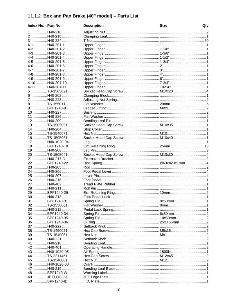
11.1.2 Box and Pan Brake (40” model) – Parts List
Index No. Part No. Description Size Qty
1 ................ H40-210 .................... Adjusting Nut .................................................... ............................................. 2 2 ................ H40-215 .................... Clamping Leaf................................................... ............................................. 1 3 ................ H40-224 .................... T-Nut ................................................................. ........................................... 20 4-1 ............. H40-201-1 ................. Upper Finger ..................................................... 1”.......................................... 1 4-2 ............. H40-201-2 ................. Upper Finger ..................................................... 1-1/8” ................................... 1 4-3 ............. H40-201-3 ................. Upper Finger ..................................................... 1-3/8” ................................... 1 4-4 ............. H40-201-4 ................. Upper Finger ..................................................... 1-1/2” ................................... 1 4-5 ............. H40-201-5 ................. Upper Finger ..................................................... 1-3/4” ................................... 1 4-6 ............. H40-201-6 ................. Upper Finger ..................................................... 2”.......................................... 1 4-7 ............. H40-201-7 ................. Upper Finger ..................................................... 3”.......................................... 1 4-8 ............. H40-201-8 ................. Upper Finger ..................................................... 4”.......................................... 1 4-9 ............. H40-201-9 ................. Upper Finger ..................................................... 6”.......................................... 1 4-10 ........... H40-201-10 ............... Upper Finger ..................................................... 7-3/4” ................................... 1 4-11 ........... H40-201-11 ............... Upper Finger ..................................................... 10-5/8” ................................. 1 5 ................ TS-1505021 .............. Socket Head Cap Screw................................... M10x20 .............................. 34 6 ................ H40-202 .................... Clamping Block ................................................. ............................................. 1 7 ................ H40-223 .................... Adjusting Nut Spring ......................................... ............................................. 2 8 ................ TS-155011 ................ Flat Washer ...................................................... 20mm ................................... 6 9 ................ BPF1240-9 ................ Grease Fitting ................................................... M8x1 .................................... 2 10 .............. H40-227 .................... Bushing ............................................................. ............................................. 2 11 .............. H40-226 .................... Flat Washer ...................................................... ............................................. 2 12 .............. H40-209 .................... Bending Leaf Pin .............................................. ............................................. 1 13 .............. TS-1505051 .............. Socket Head Cap Screw................................... M10x35 ................................ 1 14 .............. H40-204 .................... Stop Collar ........................................................ ............................................. 1 15 .............. TS-1540071 .............. Hex Nut ............................................................. M10 ...................................... 1 16 .............. TS-1505061 .............. Socket Head Cap Screw................................... M10x40 ................................ 1 17 .............. H40-1020-04 ............. Leg .................................................................... ............................................. 1 18 .............. BPF1240-18 .............. Ext. Retaining Ring ........................................... 25mm ................................. 13 19 .............. H40-208 .................... Leg Pin.............................................................. ............................................. 3 20 .............. TS-1505041 .............. Socket Head Cap Screw................................... M10x30 ................................ 4 21 .............. H40-217-3 ................. Extension Bracket ............................................. ............................................. 2 22 .............. BPF1240-22 .............. Disc Spring ....................................................... Ø40xø20x1mm .................... 4 23 .............. H40-205 .................... Rod ................................................................... ............................................. 2 24 .............. H40-206 .................... Foot Pedal Lever .............................................. ............................................. 4 25 .............. H40-207 .................... Lever Pin........................................................... ............................................. 4 26 .............. H40-216 .................... Foot Pedal ........................................................ ............................................. 1 27 .............. H40-402 .................... Tread Plate Rubber .......................................... ............................................. 1 28 .............. H40-211 .................... Roll Pin ............................................................. ............................................. 1 29 .............. BPF1240-29 .............. Ext. Retaining Ring ........................................... 10mm ................................... 2 30 .............. H40-213 .................... Foot Pedal Lock ................................................ ............................................. 1 31 .............. BPF1240-31 .............. Spring Pin ......................................................... 8x50mm ............................... 1 32 .............. TS-1550061 .............. Flat Washer ...................................................... 8mm ..................................... 1 33 .............. H40-212 .................... Pedal Lock Spring............................................. ............................................. 1 34 .............. BPF1240-34 .............. Spring Pin ......................................................... 6x50mm ............................... 2 35 .............. BPF1240-35 .............. Spring Pin ......................................................... 10x50mm ............................. 2 36 .............. BPF1240-36 .............. O-Ring .............................................................. 25x3.55mm .......................... 2 37 .............. H40-222 .................... Setback Knob ................................................... ............................................. 2 38 .............. TS-1490021 .............. Hex Cap Screw ................................................. M8x16 .................................. 2 39 .............. TS-1540061 .............. Hex Nut ............................................................. M8 ........................................ 2 40 .............. H40-221 .................... Setback Knob ................................................... ............................................. 2 41 .............. H40-218 .................... Bending Leaf..................................................... ............................................. 1 42 .............. H40-401 .................... Operating Handle.............................................. ............................................. 2 43 .............. H40-1020-05 ............. Air Spring .......................................................... 1500N .................................. 1 44 .............. TS-2211451 .............. Hex Cap Screw ................................................. M12x45 ................................ 2 45 .............. TS-1540081 .............. Hex Nut ............................................................. M12 ...................................... 2 46 .............. H40-1020-00 ............. Crank ................................................................ ............................................. 1 47 .............. H40-219 .................... Bending Leaf Blade .......................................... ............................................. 1 48 .............. BPF1240-WL............. Warning Label................................................... ............................................. 1 49 .............. JETLOGO-1 .............. JET Logo Plate ................................................. ............................................. 1 50 .............. BPF1240-ID .............. I. D. Plate .......................................................... ............................................. 1

11
11.2.1 Box and Pan Brake (50” model) – Exploded View

12
11.2.2 Box and Pan Brake (50” model) – Parts List Index No. Part No. Description Size Qty
1 ................ H40-210 .................... Adjusting Nut .................................................... ............................................. 2 2 ................ H50-215 .................... Clamping Leaf................................................... ............................................. 1 3 ................ H40-224 .................... T-Nut ................................................................. ........................................... 24 4-1 ............. H40-201-1 ................. Upper Finger ..................................................... 1”.......................................... 1 4-2 ............. H40-201-2 ................. Upper Finger ..................................................... 1-1/8” ................................... 1 4-3 ............. H40-201-3 ................. Upper Finger ..................................................... 1-3/8” ................................... 1 4-4 ............. H40-201-4 ................. Upper Finger ..................................................... 1-1/2” ................................... 1 4-5 ............. H40-201-5 ................. Upper Finger ..................................................... 1-3/4” ................................... 1 4-6 ............. H40-201-6 ................. Upper Finger ..................................................... 2”.......................................... 1 4-7 ............. H40-201-7 ................. Upper Finger ..................................................... 3”.......................................... 1 4-8 ............. H40-201-8 ................. Upper Finger ..................................................... 4”.......................................... 1 4-9 ............. H40-201-9 ................. Upper Finger ..................................................... 6”.......................................... 1 4-10 ........... H40-201-10 ............... Upper Finger ..................................................... 7-3/4” ................................... 1 4-11 ........... H50-201-11 ............... Upper Finger ..................................................... 10”........................................ 1 4-12 ........... H40-201-11 ............... Upper Finger ..................................................... 10-5/8” ................................. 1 5 ................ TS-1505021 .............. Socket Head Cap Screw................................... M10x20 .............................. 40 6 ................ H50-202 .................... Clamping Block ................................................. ............................................. 1 7 ................ H50-223 .................... Adjusting Nut Spring ......................................... ............................................. 2 8 ................ TS-155011 ................ Flat Washer ...................................................... 20mm ................................... 6 9 ................ BPF1240-9 ................ Grease Fitting ................................................... M8x1 .................................... 2 10 .............. H40-227 .................... Bushing ............................................................. ............................................. 2 11 .............. H40-226 .................... Flat Washer ...................................................... ............................................. 2 12 .............. H40-209 .................... Bending Leaf Pin .............................................. ............................................. 1 13 .............. TS-1505051 .............. Socket Head Cap Screw................................... M10x35 ................................ 1 14 .............. H40-204 .................... Stop Collar ........................................................ ............................................. 1 15 .............. TS-1540071 .............. Hex Nut ............................................................. M10 ...................................... 1 16 .............. TS-1505061 .............. Socket Head Cap Screw................................... M10x40 ................................ 1 17 .............. H50-1020-04 ............. Leg .................................................................... ............................................. 1 18 .............. BPF1240-18 .............. Ext. Retaining Ring ........................................... 25mm ................................. 13 19 .............. H40-208 .................... Leg Pin.............................................................. ............................................. 3 20 .............. TS-1505041 .............. Socket Head Cap Screw................................... M10x30 ................................ 4 21 .............. H40-217-3 ................. Extension Bracket ............................................. ............................................. 2 22 .............. BPF1240-22 .............. Disc Spring ....................................................... Ø40xø20x1mm .................... 4 23 .............. H40-205 .................... Rod ................................................................... ............................................. 2 24 .............. H40-206 .................... Foot Pedal Lever .............................................. ............................................. 4 25 .............. H40-207 .................... Lever Pin........................................................... ............................................. 4 26 .............. H50-216 .................... Foot Pedal ........................................................ ............................................. 1 27 .............. H40-402 .................... Tread Plate Rubber .......................................... ............................................. 1 28 .............. H40-211 .................... Roll Pin ............................................................. ............................................. 1 29 .............. BPF1240-29 .............. Ext. Retaining Ring ........................................... 10mm ................................... 2 30 .............. H40-213 .................... Foot Pedal Lock ................................................ ............................................. 1 31 .............. BPF1240-31 .............. Spring Pin ......................................................... 8x50mm ............................... 1 32 .............. TS-1550061 .............. Flat Washer ...................................................... 8mm ..................................... 1 33 .............. H40-212 .................... Pedal Lock Spring............................................. ............................................. 1 34 .............. BPF1240-34 .............. Spring Pin ......................................................... 6x50mm ............................... 2 35 .............. BPF1240-35 .............. Spring Pin ......................................................... 10x50mm ............................. 2 36 .............. BPF1240-36 .............. O-Ring .............................................................. 25x3.55mm .......................... 2 37 .............. H40-222 .................... Setback Knob ................................................... ............................................. 2 38 .............. TS-1490021 .............. Hex Cap Screw ................................................. M8x16 .................................. 2 39 .............. TS-1540061 .............. Hex Nut ............................................................. M8 ........................................ 2 40 .............. H40-221 .................... Setback Knob ................................................... ............................................. 2 41 .............. H50-218 .................... Bending Leaf..................................................... ............................................. 1 42 .............. H40-401 .................... Operating Handle.............................................. ............................................. 2 43 .............. H50-1020-05 ............. Air Spring .......................................................... 1800N .................................. 1 44 .............. TS-2211451 .............. Hex Cap Screw ................................................. M12x45 ................................ 2 45 .............. TS-1540081 .............. Hex Nut ............................................................. M12 ...................................... 2 46 .............. H40-1020-00 ............. Crank ................................................................ ............................................. 1 47 .............. H50-219 .................... Bending Leaf Blade .......................................... ............................................. 1 48 .............. BPF1240-WL............. Warning Label................................................... ............................................. 1 49 .............. JETLOGO-1 .............. JET Logo Plate ................................................. ............................................. 1 50 .............. BPF1450-ID .............. I. D. Plate .......................................................... ............................................. 1