Embed Size (px)
Citation preview

Operating Instructions and Parts Manual Accu-Fence® and Rail System for 64A, 64B and PM1000 Table Saws
Powermatic 427 New Sanford Road LaVergne, Tennessee 37086 Part No. M-2195075Z Ph.: 800-274-6848 Revision C2 10/2017 www.powermatic.com Copyright © 2017 Powermatic

2
1.0 Warranty and Service Powermatic warrants every product it sells against manufacturers’ defects. If one of our tools needs service or repair, please contact Technical Service by calling 1-800-274-6846, 8AM to 5PM CST, Monday through Friday.
Warranty Period The general warranty lasts for the time period specified in the literature included with your product or on the official Powermatic branded website.
• Powermatic products carry a limited warranty which varies in duration based upon the product. (See chart below)
• Accessories carry a limited warranty of one year from the date of receipt. • Consumable items are defined as expendable parts or accessories expected to become inoperable within a
reasonable amount of use and are covered by a 90 day limited warranty against manufacturer’s defects.
Who is Covered This warranty covers only the initial purchaser of the product from the date of delivery.
What is Covered This warranty covers any defects in workmanship or materials subject to the limitations stated below. This warranty does not cover failures due directly or indirectly to misuse, abuse, negligence or accidents, normal wear-and-tear, improper repair, alterations or lack of maintenance. Powermatic woodworking machinery is designed to be used with Wood. Use of these machines in the processing of metal, plastics, or other materials outside recommended guidelines may void the warranty. The exceptions are acrylics and other natural items that are made specifically for wood turning.
Warranty Limitations Woodworking products with a Five Year Warranty that are used for commercial or industrial purposes default to a Two Year Warranty. Please contact Technical Service at 1-800-274-6846 for further clarification.
How to Get Technical Support Please contact Technical Service by calling 1-800-274-6846. Please note that you will be asked to provide proof of initial purchase when calling. If a product requires further inspection, the Technical Service representative will explain and assist with any additional action needed. Powermatic has Authorized Service Centers located throughout the United States. For the name of an Authorized Service Center in your area call 1-800-274-6846 or use the Service Center Locator on the Powermatic website.
More Information Powermatic is constantly adding new products. For complete, up-to-date product information, check with your local distributor or visit the Powermatic website.
How State Law Applies This warranty gives you specific legal rights, subject to applicable state law.
Limitations on This Warranty POWERMATIC LIMITS ALL IMPLIED WARRANTIES TO THE PERIOD OF THE LIMITED WARRANTY FOR EACH PRODUCT. EXCEPT AS STATED HEREIN, ANY IMPLIED WARRANTIES OF MERCHANTABILITY AND FITNESS FOR A PARTICULAR PURPOSE ARE EXCLUDED. SOME STATES DO NOT ALLOW LIMITATIONS ON HOW LONG AN IMPLIED WARRANTY LASTS, SO THE ABOVE LIMITATION MAY NOT APPLY TO YOU. POWERMATIC SHALL IN NO EVENT BE LIABLE FOR DEATH, INJURIES TO PERSONS OR PROPERTY, OR FOR INCIDENTAL, CONTINGENT, SPECIAL, OR CONSEQUENTIAL DAMAGES ARISING FROM THE USE OF OUR PRODUCTS. SOME STATES DO NOT ALLOW THE EXCLUSION OR LIMITATION OF INCIDENTAL OR CONSEQUENTIAL DAMAGES, SO THE ABOVE LIMITATION OR EXCLUSION MAY NOT APPLY TO YOU. Powermatic sells through distributors only. The specifications listed in Powermatic printed materials and on the official Powermatic website are given as general information and are not binding. Powermatic reserves the right to effect at any time, without prior notice, those alterations to parts, fittings, and accessory equipment which they may deem necessary for any reason whatsoever.
Product Listing with Warranty Period 90 Days – Parts; Consumable items 1 Year – Motors, Machine Accessories 2 Year – Woodworking Machinery used for industrial or commercial purposes 5 Year – Woodworking Machinery
NOTE: Powermatic is a division of JPW Industries, Inc. References in this document to Powermatic also apply to JPW Industries, Inc., or any of its successors in interest to the Powermatic brand.

3
2.0 Table of Contents Section Page 1.0 Warranty and Service ............................................................................................................................. 2 2.0 Table of Contents ................................................................................................................................... 3 3.0 Safety warnings ...................................................................................................................................... 4 4.0 Unpacking .............................................................................................................................................. 6
4.1 Carton contents .................................................................................................................................. 6 5.0 Assembly ................................................................................................................................................ 7
5.1 Front Rail Installation .......................................................................................................................... 7 5.2 Back Rail Installation .......................................................................................................................... 8 5.3 Wood extension table (optional) ......................................................................................................... 8 5.4 Guide tube .......................................................................................................................................... 9 5.5 Accu-Fence installation .................................................................................................................... 10 5.6 Fence adjustments ........................................................................................................................... 10
5.6.1 Leveling fence to saw table ....................................................................................................... 10 5.6.2 Adjusting fence parallel to miter slot .......................................................................................... 10 5.6.3 Clamping pressure ..................................................................................................................... 11 5.6.4 Squaring to table ........................................................................................................................ 11 5.6.5 Scale installation ........................................................................................................................ 11 5.6.6 Cursor Adjustment ..................................................................................................................... 12
6.0 Installation on a non-Powermatic saw ................................................................................................. 12 7.0 Troubleshooting the Accu-Fence ......................................................................................................... 12 8.0 Replacement parts ............................................................................................................................... 12
8.1.1 Accu-Fence Assembly (64A/64B/PM1000) – Parts List ................................................................ 13 8.1.2 Accu-Fence Assembly (64A/64B/PM1000) – Exploded View ....................................................... 13 8.2.1 Accu-Fence Rail Assembly (64A/64B/PM1000) – Parts List ........................................................ 14 8.2.2 Accu-Fence Rail Assembly (64A/64B/PM1000) – Exploded View ................................................ 14 8.3.1 Leg Assembly for Wood Extension Table (optional) ..................................................................... 15
9.0 Appendix – Extension Table Dimensions ............................................................................................ 15
The specifications in this manual are given as general information and are not binding. Powermatic reserves the right to effect, at any time and without prior notice, changes or alterations to parts, fittings, and accessory equipment deemed necessary for any reason whatsoever.

4
3.0 Safety warnings 1. Read and understand the entire owner’s
manual before attempting assembly or operation. Also read the entire owner’s manual of the table saw on which this fence system will be used.
2. Read and understand the warnings posted on the machine and in this manual. Failure to comply with all of these warnings may cause serious injury.
3. Replace the warning labels if they become obscured or removed.
4. The table saw on which the Accu-Fence is used is designed and intended for use by properly trained and experienced personnel only. If you are not familiar with the proper and safe operation of a table saw, do not use until proper training and knowledge have been obtained.
5. Do not use the table saw on which the Accu-Fence is used for other than its intended use. If used for other purposes, Powermatic disclaims any real or implied warranty and holds itself harmless from any injury that may result from that use.
6. Always wear approved safety glasses/face shields while using this table saw. Everyday eyeglasses only have impact resistant lenses; they are not safety glasses.
7. Before operating the table saw, remove tie, rings, watches and other jewelry, and roll sleeves up past the elbows. Remove all loose clothing and confine long hair. Non-slip footwear or anti-skid floor strips are recommended. Do not wear gloves.
8. Wear ear protectors (plugs or muffs) during extended periods of operation.
9. WARNING: Drilling, sawing, sanding or machining wood products generates wood dust and other substances known to the State of California to cause cancer. Avoid inhaling dust generated from wood products or use a dust mask or other safeguards to avoid inhaling dust generated from wood products.
10. Wood products emit chemicals known to the State of California to cause birth defects or other reproductive harm. (California Health and Safety Code Section 25249.6)
11. Do not operate this machine while tired or under the influence of drugs, alcohol or any medication.
12. Make certain the switch is in the OFF position before connecting the machine to the power supply.
13. Make certain the machine is properly grounded.
14. Make all machine adjustments or maintenance with the machine unplugged from the power source.
15. Remove adjusting keys and wrenches. Form a habit of checking to see that keys and adjusting wrenches are removed from the machine before turning it on.
16. Keep safety guards in place at all times when the machine is in use. If removed for maintenance purposes, use extreme caution and replace the guards immediately.
17. Make sure the table saw is firmly placed on a secure foundation.
18. Check damaged parts. Before further use of the machine, a guard or other part that is damaged should be carefully checked to determine that it will operate properly and perform its intended function. Check for alignment of moving parts, binding of moving parts, breakage of parts, mounting and any other conditions that may affect its operation. A guard or other part that is damaged should be properly repaired or replaced.
19. Provide for adequate space surrounding work area and non-glare, overhead lighting.
20. Keep the floor around the machine clean and free of scrap material, oil and grease.
21. Keep visitors a safe distance from the work area. Keep children away.
22. Make your workshop child proof with padlocks, master switches or by removing starter keys.
23. Give your work undivided attention. Looking around, carrying on a conversation and “horse-play” are careless acts that can result in serious injury.
24. Maintain a balanced stance at all times so that you do not fall into the blade or other moving parts. Do not overreach or use excessive force to perform any machine operation.

5
25. Use the right tool at the correct speed and feed rate. Do not force a tool or attachment to do a job for which it was not designed. The right tool will do the job better and more safely.
26. Use recommended accessories; improper accessories may be hazardous.
27. Maintain tools with care. Keep saw blades sharp and clean for the best and safest performance. Follow instructions for lubricating and changing accessories.
28. Turn off the machine before cleaning. Use a brush or compressed air to remove chips or debris — do not use your hands.
29. Do not stand on the machine. Serious injury could occur if the machine tips over.
30. Never leave the machine running unattended. Turn the power off and do not leave the machine until it comes to a complete stop.
31. Remove loose items and unnecessary work pieces from the area before starting the machine.

6
4.0 Unpacking Open shipping cartons and check that all parts are intact. Report any damage immediately to your distributor. Read the instruction manual thoroughly for assembly, alignment, and maintenance instructions.
4.1 Carton contents Box One: (1) Accu-Fence (1) Lock lever knob (1) Owner’s manual (1) Warranty card Box Two: (refer to Figures 1 and 2) (1) Front rail (1) Back rail (1) Guide tube (1) Tube cap (1) Hardware bag containing:
(7) Flat Head Screws, 1/4-20 x 1-1/2 (7) Hex Cap Screws, 1/4-20 x 1-1/2 (9) Hex Cap Screws, 1/4-20 x 3/4 (28) Flat Washers, 1/4 (21) Lock Washers, 1/4 (14) Hex Nuts, 1/4
Note: The hardware is packed in the guide tube along with the tube cap. The contents of hardware bag are shown at right. Quantities for items in the hardware bag are for the 52" rail system. If you purchased the 30" rail system, or are not using an optional wood extension table, there may be extra fasteners.
Figure 1: Contents of Box #2
Figure 2: Contents of Hardware Bag

7
5.0 Assembly Tools required for assembly & adjustments:
10mm open-end wrenches (or sockets with ratchet wrench)
Cross point screwdriver #3 Hex keys, 5mm and 6mm Combination square Adjustable square Rubber mallet (or hammer and wood block) Straight edge
Additional tools required for optional wood extension table:
Electric drill 1/4” drill bit C-clamps, 4” or 6”
The following instructions are for installing the Accu-Fence and Rail System on a Powermatic Model 64A, 64B or PM1000 Table Saw. The rails should bolt to the Powermatic saw without any drilling.
5.1 Front Rail Installation Refer to Figure 3:
1. Identify the front rail, which is 2" x 2" with holes running along each side.
2. Align the countersunk holes on the front rail to the four holes in front edge of saw table, as shown in Figure 3. (The slotted holes will face down.)
Refer to Figure 4:
3. Lightly secure front rail to saw table and extension wings, with four 1/4 x 1-1/2 flat head screws, four flat washers, four lock washers, and four hex nuts. Tighten just enough to hold rail next to table but keep loose enough to allow height adjustment.
The front rail must be parallel to the table top in order for the Accu-Fence system to function properly.
4. Place an adjustable square on the table as shown in Figure 5.
5. Check the height of the front rail at several locations along the surface of the saw table. The measurements should be the same along the length of the rail. (Generally, this dimension will be about 2-1/4”.)
6. When the front rail has been correctly positioned, tighten all hex nuts securely with a 10mm wrench.
Figure 3
Figure 4
Figure 5

8
5.2 Back Rail Installation Refer to Figure 6:
1. The back rail is 1-1/2" x 1-1/2" with holes and slots running along one side only. The height of the back rail when attached to the saw is not critical.
2. Align the holes in the back rail to the holes in the table top, as shown in Figure 6.
Refer to Figure 7:
3. Secure the back rail to the holes in the saw table with two 1/4 x 1-1/2 hex cap screws, four flat washers, two lock washers, and two hex nuts as shown in Figure 7. Tighten nuts securely with 10mm wrench.
(On the PM1000 Table Saw, use 1/4 x 3/4 screws at the two center holes, which are threaded and will not require hex nuts.)
NOTE: If you are installing an optional wood extension table on your saw, it should be installed first before mounting the guide tube. This will prevent having to mount and align the guide tube twice.
If you are not mounting an optional wood extension table, skip the following section and proceed to section 5.4, Guide Tube.
5.3 Wood extension table (optional) The wood extension table is an optional accessory.
The wood extension table (including the optional router table) sits flush against the saw table and along the inside of the rails. The Powermatic logo (or warning label on the router table) should face outward. The extension table is not bolted to the saw table, it is bolted only to the rails.
The extension table and saw table must be aligned properly so the Accu-Fence will slide smoothly from one to the other.
1. Mount the two legs to the inside corners of the extension table (at the end with the Powermatic name) See Figure 8. Secure with the eight screws provided with the legs. The foot pads on the legs can be rotated to adjust for height.
Note: If you are using a mobile base under your saw, you may need to shift placement of the legs so they rest properly upon the base shelves.
2. Place extension table between the rails and up against the saw table, leaving the extension table raised just slightly above the saw table.
3. Clamp the extension table to the front and back rails as shown in Figure 9. Clamping pressure should be enough to secure the table yet allow minor adjustments.
4. Use a hammer and block of wood (or a rubber mallet) to tap the extension table up flush against the cast iron saw table (Figure 9).
Figure 6
Figure 7
Figure 8
Figure 9

9
5. Lay a straight edge across both extension table and saw table to ensure proper leveling. Tap down the extension table at various points along its edge where it meets the saw table, until it is level with the saw table (Figure 10). As one part of the edge becomes level with the table, tighten the clamp on that side. Then move to the other side and repeat, until the full length of the edge is level with the saw table.
NOTE: An alternate method of aligning table surfaces is to use additional clamps at front and back. Clamp a flat piece of wood that spans the seam between saw table and wood extension table, and tighten clamp until table surfaces are even. Additional adjustment may be necessary for full alignment.
6. When extension table is properly aligned and clamps are tight, drill holes into the wood table using the holes in the rails as your guide, as follows (Figure 11).
Note: For the following steps, you may wish to drill 3/32" pilot holes first.
7. Drill 1/4" holes into front facing of wood table using the holes in the front rail as a guide.
8. Drill 1/4" holes into back facing of wood table using the holes in the back rail as a guide.
9. Install 1/4 x 1-1/2 flat head screws into front rail and secure behind the wood table facing with 1/4 flat washers, lock washers and hex nuts. Finger-tighten only.
10. Install 1/4 x 1-1/2 hex cap screws with 1/4 flat washers into rear rail, and secure behind wood table facing with 1/4 flat washers, lock washers and hex nuts. Finger-tighten only.
11. Re-check the table for alignment, make further adjustments if necessary, then tighten all screws and nuts with 10mm wrench.
12. Rotate the footpads on the legs until they reach the floor, then tighten the nut.
5.4 Guide tube Refer to Figure 13:
The guide tube (A) is placed on top the front rail (B) and is mounted with the scale facing toward the operator.
1. Align holes in bottom of guide tube (A) with holes in front rail (B).
2. Fasten guide tube to rail from beneath with 1/4 x 3/4 hex cap screws (C), lock washers (F) and flat washers (G). Finger-tighten only.
3. Measure from guide tube to table edge in several places, to ensure it is parallel with table top. Adjust as needed, and tighten all screws with a 10mm wrench.
Figure 10
Figure 11
Figure 12
Figure 13

10
4. Press tube cap into opening of guide tube. Use a rubber mallet if needed to drive it on.
5. The measurement scale will be applied to the guide tube in section 5.6.5, Scale Installation.
5.5 Accu-Fence installation Screw the lock lever knob into the threaded handle on the Accu-Fence, as shown in Figure 14.
The lock lever has three functional positions as shown in Figure 15:
• Upright position permits mounting and removal of fence from saw.
• Unlock position permits easy fence positioning.
• Lower position locks fence to front rail. The cam handle should be pushed down firmly against the pin.
5.6 Fence adjustments Fence adjustments should be performed in the order given.
5.6.1 Leveling fence to saw table 1. Place fence on table and lock it.
2. View the fence from the left side of saw (Figure 16). Look for the space between the table and the fence bottom to be equal along the entire length of the fence.
If adjustment is necessary:
3. Unlock the fence.
4. Raise or lower two nylon adjustment screws (Figure 17) the same number of turns until the space between the bottom of the fence and the table is the same. Care must be taken to raise or lower the fence on each side equally or the fence sides may not be 90° to the table after the height adjustment is performed.
5.6.2 Adjusting fence parallel to miter slot 1. Place the fence next to the outside edge of the
right miter slot and lock it (Figure 18).
2. The fence should be even with the miter slot from front to back.
3. If the fence is not even along the length of the miter slot, unlock the fence and lift up the front end.
4. Adjust one of the two setscrews (Figure 19) until the fence is even with the miter slot edge along its entire length when locked.
Note: You may need to re-adjust the clamping pressure after aligning the fence.
Figure 14
Figure 15
Figure 16
Figure 17

11
5.6.3 Clamping pressure The Accu-Fence has been adjusted at the factory to lock securely when the lock handle is pushed down. If adjustment is needed:
1. Unlock fence and lift up the front end.
2. Adjust each of the two setscrews (Figure 19) exactly the same number of rotations until desired pressure is achieved when the lock handle is pushed down. Rotate counter-clockwise to increase cam pressure and clockwise to decrease.
5.6.4 Squaring to table 1. Place fence on saw table and lock it.
2. Place a square (Figure 18) on the table next to the fence. The fence sides should be 90° to the table.
3. If adjustment is necessary, unlock the fence, and turn one of the two nylon adjustment screws (Figure 17) until fence is 90° to table.
4. Lock the fence and check the adjustment again.
5.6.5 Scale installation The measurement scale supplied with the 64B and PM1000 rail system is now shipped unattached, as each of these models requires a different scale position. The scale may be easily applied by the operator according to the following instructions. There is a short or a long scale, depending upon which guide tube length you received.
This procedure should be performed after completing section 5.6.4, Squaring to Table.
To install new scale, familiarize yourself with all of the following steps, then begin the procedure.
1. Remove blade guard from saw.
2. Install blade and raise it to full height.
3. Position Accu-Fence so that it contacts side of blade.
4. Loosen fence cursor and slide it to middle position. (This will allow space for future adjustment left and right.)
5. Place a pencil mark on guide tube at the cursor line.
6. Remove Accu-Fence.
7. Peel away the backing from left end of scale. Carefully apply left end of scale so that zero aligns with your mark. (Make sure scale is parallel to edge of guide tube, and positioned toward front edge of guide tube so it is sufficiently visible when Accu-Fence is installed.)
8. Continue to remove the backing as you apply the scale toward right end of guide tube.
9. Reinstall Accu-Fence against side of blade, and make further adjustments if needed, until cursor is zeroed with scale.
Figure 18
Figure 19
Figure 20
Figure 21

12
5.6.6 Cursor Adjustment 1. Disconnect table saw from power source.
2. Raise saw blade above the tabletop.
3. Unlock fence and slide it to approximately two inches from saw blade.
4. Lock the fence.
5. Measure the distance from right edge of saw blade to the fence.
6. Adjust the cursor (Figure 21) to read the distance just measured and tighten the cursor assembly to the fence.
7. Make a test cut and measure work piece to confirm that the cursor adjustment is correct. Make further adjustments if needed.
Note: If the cursor does not have enough travel to give the correct measurement, loosen the guide tube and adjust as needed. If you still do not get the correct measurement loosen the front rail and adjust as needed. If you have to adjust the front rail you will need to go through the front rail assembly instructions again.
Cursor adjustment should be checked whenever a different blade is installed.
6.0 Installation on a non-Powermatic saw
This Accu-Fence and Rail System can be installed on a non-Powermatic table saw. Instructions for the rail and fence installation as well as the optional extension table are provided in Manual No. M-2195075EZ and is available on-line or a copy can be obtained by contacting customer service.
7.0 Troubleshooting the Accu-Fence Problem Possible Cause Solution Lock lever won't go down, or requires excessive force.
Too much pressure against guide tube.
Back out set screws.
Fence scrapes table, won't slide smoothly.
Fence height not adjusted properly.
Adjust nylon screws.
Fence "hangs" or binds while sliding.
Front rail not level. Readjust rail.
Cuts not straight, or workpiece binds during rip cuts.
Fence not properly aligned with blade. (See your table saw manual for other causes of this problem.)
Align fence with table miter slot.
8.0 Replacement parts Ordering parts
To order parts or reach our service department, call 1-800-274-6848 Monday through Friday (see our website for business hours, www.powermatic.com). Having the Model Number and Serial Number of your machine available when you call will allow us to serve you quickly and accurately.

13
8.1.1 Accu-Fence Assembly (64A/64B/PM1000) – Parts List
Index No. Part No. Description Size Qty 1 ................ HF2-101 .................... Left Side Plate ......................................................... ...................................... 1 2 ................ AF-102 ...................... Fence Body Assembly ............................................. ...................................... 1 3 ................ PM1000-10 ................ Tube Cap, Powermatic ............................................ ...................................... 1 4 ................ HF2-104 .................... Right Side Plate ....................................................... ...................................... 1 5 ................ TS-0640071 .............. Lock Nut................................................................... 1/4” -20 ........................ 10 6 ................ TS-0271031 .............. Socket Set Screw .................................................... 3/8”-16 x 3/8” ................. 2 7 ................ 3575081 .................... Fluoroway Pad ......................................................... ...................................... 2 8 ................ XF2-108 .................... Pad .......................................................................... ...................................... 1 9 ................ TS-0151011 .............. Carriage Bolt ............................................................ 1/4”-20 x 3/4” ............... 10 10 .............. TS-081D022 .............. Pan Head Machine Screw ....................................... 10-32 x 3/8” ................... 2 11 .............. TS-0680021 .............. Flat Washer ............................................................. 1/4” ................................ 2 12 .............. HF2-112 .................... Cursor ...................................................................... ...................................... 1 13 .............. 3408241 .................... Accu-Fence Label .................................................... ...................................... 1 14 .............. 3312341 .................... Powermatic Label .................................................... ...................................... 1 15 .............. TS-0640071 .............. Lock Nut................................................................... 1/4”-20 .......................... 1 16 .............. TS-0640081 .............. Lock Nut................................................................... 5/16”-18 ........................ 1 17 .............. XF2-117 .................... Spring Pin ................................................................ 4mm x 28 ...................... 1 18 .............. 6813042 .................... Compression Spring ................................................ ...................................... 1 19 .............. TS-0151041 .............. Carriage Bolt ............................................................ 1/4”-20 x 1-1/2” ............. 1 20 .............. TS-0152031 .............. Carriage Bolt ............................................................ 5/16”-18 x 1-1/2” ........... 1 21 .............. 3215302 .................... Foot Cam ................................................................. ...................................... 1 22 .............. 3076232 .................... Lock Cam................................................................. ...................................... 1 23 .............. 6430055 .................... Knob w/stud ............................................................. 3/8”-16 x 5/8” ................ 1 24 .............. XF-5 .......................... Nylon Adjustment Screw.......................................... ...................................... 2
8.1.2 Accu-Fence Assembly (64A/64B/PM1000) – Exploded View
1 2
3
4
5 ( )5
( )5 5
8
9 ( )5
( )210
11
12
6 2( )
24 2( )
1920
21
22
23 15
18
17
16
2( )7
( )2
13
14
14
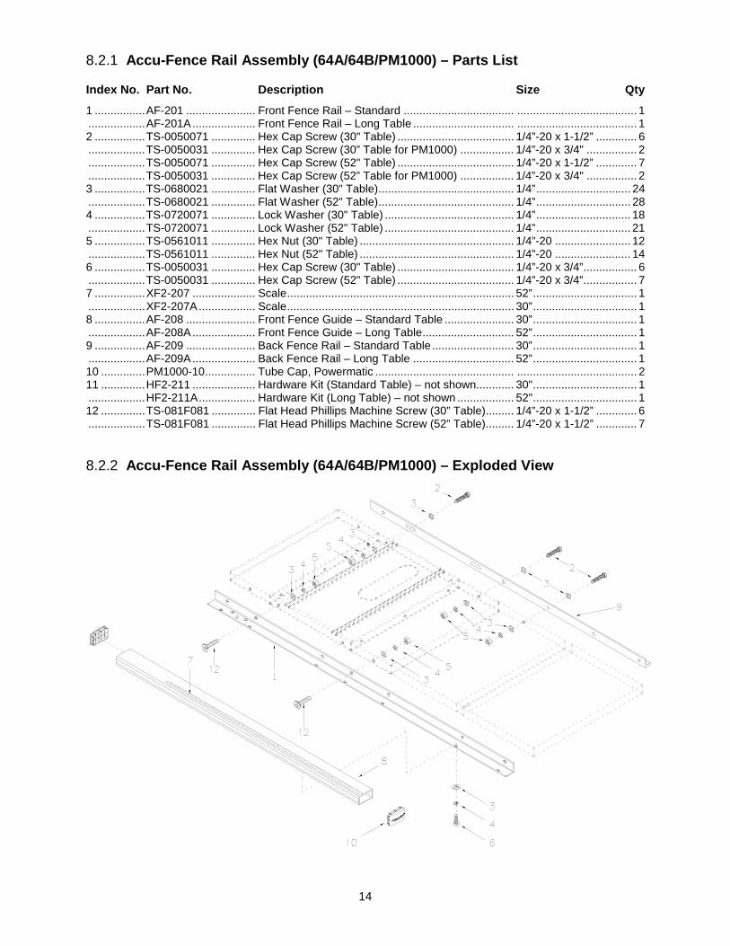
8.2.1 Accu-Fence Rail Assembly (64A/64B/PM1000) – Parts List
Index No. Part No. Description Size Qty 1 ................ AF-201 ...................... Front Fence Rail – Standard ................................... ...................................... 1 .................. AF-201A .................... Front Fence Rail – Long Table ................................ ...................................... 1 2 ................ TS-0050071 .............. Hex Cap Screw (30" Table) ..................................... 1/4”-20 x 1-1/2” ............. 6 .................. TS-0050031 .............. Hex Cap Screw (30” Table for PM1000) ................. 1/4”-20 x 3/4" ................ 2 .................. TS-0050071 .............. Hex Cap Screw (52" Table) ..................................... 1/4”-20 x 1-1/2” ............. 7 .................. TS-0050031 .............. Hex Cap Screw (52” Table for PM1000) ................. 1/4”-20 x 3/4" ................ 2 3 ................ TS-0680021 .............. Flat Washer (30" Table) ........................................... 1/4” .............................. 24 .................. TS-0680021 .............. Flat Washer (52" Table) ........................................... 1/4” .............................. 28 4 ................ TS-0720071 .............. Lock Washer (30" Table) ......................................... 1/4” .............................. 18 .................. TS-0720071 .............. Lock Washer (52" Table) ......................................... 1/4” .............................. 21 5 ................ TS-0561011 .............. Hex Nut (30" Table) ................................................. 1/4”-20 ........................ 12 .................. TS-0561011 .............. Hex Nut (52" Table) ................................................. 1/4”-20 ........................ 14 6 ................ TS-0050031 .............. Hex Cap Screw (30" Table) ..................................... 1/4”-20 x 3/4” ................. 6 .................. TS-0050031 .............. Hex Cap Screw (52" Table) ..................................... 1/4”-20 x 3/4” ................. 7 7 ................ XF2-207 .................... Scale ........................................................................ 52” ................................. 1 .................. XF2-207A .................. Scale ........................................................................ 30” ................................. 1 8 ................ AF-208 ...................... Front Fence Guide – Standard Table ...................... 30” ................................. 1 .................. AF-208A .................... Front Fence Guide – Long Table ............................. 52” ................................. 1 9 ................ AF-209 ...................... Back Fence Rail – Standard Table .......................... 30” ................................. 1 .................. AF-209A .................... Back Fence Rail – Long Table ................................ 52” ................................. 1 10 .............. PM1000-10 ................ Tube Cap, Powermatic ............................................ ...................................... 2 11 .............. HF2-211 .................... Hardware Kit (Standard Table) – not shown............ 30" ................................. 1 .................. HF2-211A .................. Hardware Kit (Long Table) – not shown .................. 52" ................................. 1 12 .............. TS-081F081 .............. Flat Head Phillips Machine Screw (30” Table)......... 1/4”-20 x 1-1/2” ............. 6 .................. TS-081F081 .............. Flat Head Phillips Machine Screw (52” Table)......... 1/4”-20 x 1-1/2” ............. 7
8.2.2 Accu-Fence Rail Assembly (64A/64B/PM1000) – Exploded View

15
8.3.1 Leg Assembly for Wood Extension Table (optional)
Index No. Part No. Description Size Qty 1 ................ AF-301 ...................... Leg ........................................................................... ...................................... 2 2 ................ TS-0561031 .............. Hex Nut .................................................................... 3/8”-16 .......................... 2 3 ................ XF2-303 .................... Adjusting foot ........................................................... ...................................... 2 4 ................ TS-1533052 .............. Machine Screw ........................................................ M5 x 16 ......................... 8 5 ................ XF2-305 .................... Metal Insert .............................................................. 30 x 30mm .................... 2
9.0 Appendix – Extension Table Dimensions The dimensions below are provided if you plan to build your own extension table instead of purchasing one that is available through Powermatic.

16
427 New Sanford Rd. LaVergne, TN 37086 Phone: 800-274-6848 www.powermatic.com