Embed Size (px)
Citation preview

Operating Instructions and Parts Manual 22-inch Planer Models 201 and 201HH
Powermatic 427 New Sanford Road LaVergne, Tennessee 37086 Part No. M-0460224 Ph.: 800-274-6848 Revision J2 03/2019 www.powermatic.com Copyright © 2015 Powermatic

2
Warranty and Service Powermatic warrants every product it sells against manufacturers’ defects. If one of our tools needs service or repair, please contact Technical Service by calling 1-800-274-6846, 8AM to 5PM CST, Monday through Friday.
Warranty Period The general warranty lasts for the time period specified in the literature included with your product or on the official Powermatic branded website.
Powermatic products carry a limited warranty which varies in duration based upon the product. (See chart below)
Accessories carry a limited warranty of one year from the date of receipt. Consumable items are defined as expendable parts or accessories expected to become inoperable within a
reasonable amount of use and are covered by a 90 day limited warranty against manufacturer’s defects.
Who is Covered This warranty covers only the initial purchaser of the product from the date of delivery.
What is Covered This warranty covers any defects in workmanship or materials subject to the limitations stated below. This warranty does not cover failures due directly or indirectly to misuse, abuse, negligence or accidents, normal wear-and-tear, improper repair, alterations or lack of maintenance. Powermatic woodworking machinery is designed to be used with Wood. Use of these machines in the processing of metal, plastics, or other materials outside recommended guidelines may void the warranty. The exceptions are acrylics and other natural items that are made specifically for wood turning.
Warranty Limitations Woodworking products with a Five Year Warranty that are used for commercial or industrial purposes default to a Two Year Warranty. Please contact Technical Service at 1-800-274-6846 for further clarification.
How to Get Technical Support Please contact Technical Service by calling 1-800-274-6846. Please note that you will be asked to provide proof of initial purchase when calling. If a product requires further inspection, the Technical Service representative will explain and assist with any additional action needed. Powermatic has Authorized Service Centers located throughout the United States. For the name of an Authorized Service Center in your area call 1-800-274-6846 or use the Service Center Locator on the Powermatic website.
More Information Powermatic is constantly adding new products. For complete, up-to-date product information, check with your local distributor or visit the Powermatic website.
How State Law Applies This warranty gives you specific legal rights, subject to applicable state law.
Limitations on This Warranty POWERMATIC LIMITS ALL IMPLIED WARRANTIES TO THE PERIOD OF THE LIMITED WARRANTY FOR EACH PRODUCT. EXCEPT AS STATED HEREIN, ANY IMPLIED WARRANTIES OF MERCHANTABILITY AND FITNESS FOR A PARTICULAR PURPOSE ARE EXCLUDED. SOME STATES DO NOT ALLOW LIMITATIONS ON HOW LONG AN IMPLIED WARRANTY LASTS, SO THE ABOVE LIMITATION MAY NOT APPLY TO YOU. POWERMATIC SHALL IN NO EVENT BE LIABLE FOR DEATH, INJURIES TO PERSONS OR PROPERTY, OR FOR INCIDENTAL, CONTINGENT, SPECIAL, OR CONSEQUENTIAL DAMAGES ARISING FROM THE USE OF OUR PRODUCTS. SOME STATES DO NOT ALLOW THE EXCLUSION OR LIMITATION OF INCIDENTAL OR CONSEQUENTIAL DAMAGES, SO THE ABOVE LIMITATION OR EXCLUSION MAY NOT APPLY TO YOU. Powermatic sells through distributors only. The specifications listed in Powermatic printed materials and on the official Powermatic website are given as general information and are not binding. Powermatic reserves the right to effect at any time, without prior notice, those alterations to parts, fittings, and accessory equipment which they may deem necessary for any reason whatsoever.
Product Listing with Warranty Period
90 Days – Parts; Consumable items 1 Year – Motors, Machine Accessories 2 Year – Woodworking Machinery used for industrial or commercial purposes 5 Year – Woodworking Machinery
NOTE: Powermatic is a division of JPW Industries, Inc. References in this document to Powermatic also apply to JPW Industries, Inc., or any of its successors in interest to the Powermatic brand.

3
Table of Contents Warranty and Service .................................................................................................................................... 2 Table of Contents .......................................................................................................................................... 3 Warning ......................................................................................................................................................... 4 Introduction ................................................................................................................................................... 5 Specifications ................................................................................................................................................ 6 Receiving....................................................................................................................................................... 7 Installation ..................................................................................................................................................... 7
Installing Dust Hood .................................................................................................................................. 8 Grounding Instructions .................................................................................................................................. 8 Inspection ...................................................................................................................................................... 9 Adjustments .................................................................................................................................................. 9
Depth of Cut .............................................................................................................................................. 9 Feed Rate Adjustment ............................................................................................................................... 9 Belt Tension ............................................................................................................................................... 9 Opening Hood ......................................................................................................................................... 10 Knife Installation and Adjustment (Straight Cutterhead only) ................................................................ 10 Replacing or Rotating Knife Inserts (Helical Cutterhead only) ................................................................ 11
The Planer’s Feed System .......................................................................................................................... 12 Anti-Kickback Fingers .............................................................................................................................. 12 Infeed Roller ............................................................................................................................................ 12 Chipbreaker ............................................................................................................................................. 13 Pressure Bar ............................................................................................................................................ 13 Outfeed Roller ......................................................................................................................................... 14 Table Rollers ........................................................................................................................................... 14 Table Adjustments ................................................................................................................................... 15
Operating Controls ...................................................................................................................................... 16 Test Cutting and Troubleshooting ............................................................................................................... 16 Maintenance ................................................................................................................................................ 18
Lubrication ............................................................................................................................................... 18 Troubleshooting: Planer Operating Problems ............................................................................................. 19 Troubleshooting: Mechanical and Electrical Problems ............................................................................... 20 Replacement Parts ...................................................................................................................................... 21
Parts List: Base Assembly ....................................................................................................................... 22 Gearbox Assembly .................................................................................................................................. 24 Parts List: Gearbox Assembly ................................................................................................................. 25 Column Assembly .................................................................................................................................... 26 Parts List: Column Assembly .................................................................................................................. 27 Table Assembly ....................................................................................................................................... 28 Parts List: Table Assembly ...................................................................................................................... 29 Parts List: Top Cover Assembly .............................................................................................................. 30 Cutterhead Assembly .............................................................................................................................. 31 Parts List: Cutterhead Assembly ............................................................................................................. 32
Electrical Connections – 1 Phase, 230 Volt ................................................................................................ 34 Electrical Connections – 3 Phase, 230 Volt ................................................................................................ 35

4
Warning
1. Read and understand the entire owner’s manual before attempting assembly or operation.
2. Read and understand the warnings posted on the machine and in this manual. Failure to comply with all of these warnings may cause serious injury.
3. Replace the warning labels if they become obscured or removed.
4. This planer is designed and intended for use by properly trained and experienced personnel only. If you are not familiar with the proper and safe operation of a planer, do not use until proper training and knowledge have been obtained.
5. Do not use this planer for other than its intended use. If used for other purposes, Powermatic disclaims any real or implied warranty and holds itself harmless from any injury that may result from that use.
6. Always wear approved safety glasses/face shields while using this planer. Everyday eyeglasses only have impact resistant lenses; they are not safety glasses.
7. Before operating this planer, remove tie, rings, watches and other jewelry, and roll sleeves up past the elbows. Remove all loose clothing and confine long hair. Non-slip footwear or anti-skid floor strips are recommended. Do not wear gloves.
8. Wear ear protectors (plugs or muffs) during extended periods of operation.
9. Do not operate this machine while tired or under the influence of drugs, alcohol or any medication.
10. Make certain the machine is properly grounded.
11. With the exception of feed rate adjustment, make all machine adjustments or maintenance with the machine disconnected from the power source. A machine under repair should be RED TAGGED to show it should not be used until the maintenance is complete.
12. Remove adjusting keys and wrenches. Form a habit of checking to see that keys and adjusting wrenches are removed from the machine before turning it on.
13. Keep safety guards in place at all times when the machine is in use. If removed for maintenance purposes, use extreme caution and replace the guards immediately after completion of maintenance.
14. Check damaged parts. Before further use of the machine, a guard or other part that is damaged should be carefully checked to determine that it will operate properly and perform its intended function. Check for alignment of moving parts, binding of moving parts, breakage of parts, mounting and any other conditions that may affect its operation. A guard or other part that is damaged should be properly repaired or replaced.
15. Provide for adequate space surrounding work area and non-glare, overhead lighting.
16. Keep the floor around the machine clean and free of scrap material, oil and grease.
17. Keep visitors a safe distance from the work area. Keep children away.
18. Make your workshop child proof with padlocks, master switches or by removing starter keys.
19. Give your work undivided attention. Looking around, carrying on a conversation and “horse-play” are careless acts that can result in serious injury.
20. Maintain a balanced stance at all times so that you do not fall or lean against moving parts. Do not overreach or use excessive force to perform any machine operation. Stand to the side out of line with the table and make sure no one else is standing in line with the table.
21. Use the right tool at the correct speed and feed rate. Do not force a tool or attachment to do a job for which it was not designed. The right tool will do the job better and more safely.
22. Maintain tools with care. Keep knives sharp and clean for the best and safest performance. Dull tools increase noise levels and can cause kickbacks and glazed surfaces. Broken gibs/knives that are not securely locked in the cutterhead can be thrown out of the planer causing severe or fatal injury as well as severe damage to the machine. Follow instructions for lubricating machine and changing accessories. Use recommended accessories; improper accessories may be hazardous.

5
23. Do not attempt to plane boards shorter than 10” (254mm) in length without butting a board of equal thickness behind it to help it through the planer. Be sure the last board of a butted sequence is 10” or longer.
24. Do not feed stacked boards through a planer; a kickback may occur causing severe or fatal injury.
25. Do not plane a board with loose knots or with nails or any foreign material on its surface. Twisted, warped, or wind-in stock should first be jointed on one surface before attempting to plane a parallel surface on the planer. Serious stock flaws cannot be removed by use of a planer alone.
26. If the board being planed stops feeding, disengage or turn the feed off and turn the power off. Wait until the cutterhead comes to a complete stop before lowering the table to remove the board. Never lower the table with the power on and the stock still in the machine, as a kickback can occur.
27. Keep hands outside of the machine. Never reach under the guards to try to clear stock that has stopped feeding. When starting a cut, do not have any part of the hands under that part of the board that is over the table; the infeed roller will engage the board and force it down against the table causing a pinching action.
28. Disconnect machine from power source before cleaning. Use a brush or compressed air to remove chips or debris — do not use your hands.
29. Do not stand on the machine. Serious injury could occur if the machine tips over.
30. Never leave the machine running unattended. Turn the power off and do not leave the machine until it comes to a complete stop.
31. Remove loose items and unnecessary work pieces from the area before starting the machine.
Familiarize yourself with the following safety notices used in this manual:
This means that if precautions are not heeded, it may result in minor injury and/or possible machine damage.
This means that if precautions are not heeded, it may result in serious injury or possibly even death.
- - SAVE THESE INSTRUCTIONS - -
Introduction This manual is provided by Powermatic covering the safe operation and maintenance procedures for a Powermatic Model 201 and 201HH Planer. This manual contains instructions on installation, safety precautions, general operating procedures, maintenance instructions and parts breakdown. This machine has been designed and constructed to provide consistent, long-term operation if used in accordance with instructions set forth in this manual. If there are any questions or comments, please contact either your local supplier or Powermatic. Powermatic can also be reached at our web site: www.powermatic.com.
WARNING: Drilling, sawing, sanding or machining wood products generates wood dust and other substances known to the State of California to cause cancer. Avoid inhaling dust generated from wood products or use a dust mask or other safeguards for personal protection.
Wood products emit chemicals known to the State of California to cause birth defects or other reproductive harm. For more information go to http://www.p65warnings.ca.gov/wood.
WARNING: This product can expose you to chemicals including lead which is known to the State of California to cause cancer and birth defects or other reproductive harm. For more information go to http://www.p65warnings.ca.gov.

6
Specifications Model Number .......................................................................... 201 ..................................................... 201HH Stock Number (7.5HP, 1Ph, 230V) .................................. 1791261 .................................................. 1791267 Stock Number (7.5HP, 3Ph, 230V) ................................................ .................................................. 1791268 Working Width (in.) ..................................................................... 22 ............................................................ 22 Maximum Depth of Cut (in.) .................................................... 3/16 ......................................................... 3/16 Minimum Thickness (in.) ........................................................... 1/8 ........................................................... 1/8 Maximum Thickness (in.) ....................................................... 9-1/4 ........................................................ 9-1/4 Segmented Infeed Roller Diameter (in.) ...................................... 3 .............................................................. 3 Steel Outfeed Roller Diameter (in.) .............................................. 3 .............................................................. 3 Feed Speeds (FPM) ....................................................... 20 and 30 ................................................ 20 and 30 Bed Rollers, Front Adjustable ...................................................... 2 .............................................................. 2 Minimum Length Workpiece (in.) ............................................... 10 ............................................................ 10 Cutterhead Style ................................................................ straight ...................................................... helical Cutterhead Diameter (in.) ....................................................... 3-1/4 ........................................................ 3-1/4 Number of Knives ......................................................................... 4 ............................. 125 four-sided inserts Number of Cutterhead Rows .................................................... n/a .............................................................. 5 Cutterhead Speed (RPM) ....................................................... 4800 ........................................................ 4800 Cuts per Minute ................................................................... 19,200 .......................................... not applicable Table Size (LxW)(in.) ................................................... 32-1/2 x 24 .............................................. 32-1/2 x 24 Table Support .................................................................. 2-column ................................................. 2-column Manual Table Height Adjustment (in.) ........................1 turn = 1/16 ............................................ 1 turn = 1/16 Readout Scale ...................................................................... mm/in ...................................................... mm/in Dust Port Diameter (in.) ............................................................... 5 .............................................................. 5 Dust Collection Minimum CFM Required ................................. 900 .......................................................... 900 Shipping Weight, approximate (lbs.) ...................................... 1430 ........................................................ 1430 Net Weight, approximate (lbs.) .............................................. 1350 ........................................................ 1350 Overall Dimensions (LxWxH)(in.) ............................... 42 x 49 x 59 ............................................ 42 x 49 x 59
The above specifications were current at the time this manual was published, but because of our policy of continuous improvement, Powermatic reserves the right to change specifications at any time and without prior notice, without incurring obligations.
7
Receiving Open shipping crate and check for shipping damage. Report any damage immediately to your distributor. Read the instruction manual thoroughly for assembly, maintenance and safety instructions. Contents of crate: 1 planer 1 dust chute w/ fasteners
4 screws w/ hex nuts (for leveling feet) 4 leveling feet 1 knife-setting gauge (201 only)
2 star point screwdrivers (201HH only) 1 set of 10 knife inserts (201HH only) 10 knife insert screws (201HH only) 1 6mm hex wrench 1 8mm hex wrench 1 10mm hex wrench 1 12mm & 14mm wrench 1 22mm & 24mm wrench 1 Operating Instructions and Parts Manual 1 Warranty Card
Installation Remove the screws holding the base of the machine to the skid. Use the lifting eyes on front and back of the planer for hoisting it off the skid. See Figure 1. Make sure the hex nuts are tightened before lifting. The lifting eyes can be removed once the planer is situated.
Place the planer on a solid foundation, preferably a concrete floor. The four leveling feet should be placed beneath the corners, and the screws and hex nuts used for leveling adjustments. See Figure 2. Alternatively, you can secure the machine to the floor by using lag screws through the holes in the base.
The machine area should be clean, dry, well ventilated, and well lighted. Since planers can create noise problems, the site selection should be one which minimizes reverberant sound from walls, ceilings and other equipment. Electricals should be installed so that they are protected from damage and exposure.
Exposed metal parts have been given a protective coating at the factory. This should be removed with a soft rag and kerosene or a good commercial solvent. Do not use an abrasive pad, as it may scratch polished metal surfaces.
IMPORTANT: All knives or knife inserts on the cutterhead should be checked for tightness before operating the planer.
Figure 1
Figure 2

8
Installing Dust Hood
Mount the dust hood with the eight M6 x 10mm hex screws, eight spring washers, and eight flat washers. See Figure 3.
It is strongly recommended that a dust collection system be connected to the 5” port on the planer’s dust hood. The system should be of sufficient volume for this size planer. If a dust collection system is not used, the user is cautioned against the health hazard and the limitations in the OSHA regulation for employee or student exposure to dust particles.
Contact your dealer or visit waltermeier.com for a line of available dust collectors.
Grounding Instructions
Electrical connections must be made by a qualified electrician in compliance with all relevant codes. This machine must be properly grounded to help prevent electrical shock and possible fatal injury.
This machine must be grounded. In the event of a malfunction or breakdown, grounding provides a path of least resistance for electric current to reduce the risk of electric shock.
Improper connection of the equipment-grounding conductor can result in a risk of electric shock. The conductor with insulation having an outer surface that is green with or without yellow stripes, is the equipment-grounding conductor. If repair or replacement of the electric cord or plug is necessary, do not connect the equipment-grounding conductor to a live terminal.
Check with a qualified electrician or service personnel if the grounding instructions are not completely understood, or if in doubt as to whether the tool is properly grounded.
Make sure the voltage of your power supply matches the specifications on the motor plate of the Planer. The machine should be connected to a dedicated circuit.
You may either install a plug or “hard-wire” the Planer directly to a control panel. If the Planer is to be hard-wired to a panel, make sure a disconnect is available for the operator. During hard-wiring of the Planer, make sure the fuses have been removed or the breakers have been tripped in the circuit to which the machine will be connected. Place a warning placard on the fuse holder or circuit breaker to prevent it being turned on while the Planer is being wired.
Figure 3

9
Inspection Before putting power to the machine, check that all screws are tight, that all mechanical functions work freely and that the cutterhead turns freely without knife contact with the chipbreaker or pressure bar. On the helical cutterhead model, check that all knife inserts are properly torqued.
Adjustments Tools required: Philips screwdriver Hex wrenches (provided) Open-end wrench (provided)
Depth of Cut
Depth of cut is controlled by raising or lowering the table. This is done by using the handwheel (A), shown in Figure 4.
1. Loosen the lock knob (B, Figure 4).
2. Raise or lower the table to the desired position (clockwise to raise). One revolution of the handwheel equals 1/16". The distance can be read on the scale (C, Figure 4).
3. Retighten lock knob (B, Figure 4).
4. The pointer (D, Figure 4) can be adjusted slightly if the scale should ever need recalibrating.
Feed Rate Adjustment
The Model 201 is equipped with selectable feed speed rollers that feed stock at 20 and 30 feet per minute. To adjust speed, turn lever shown in Figure 5, while the planer is running.
Always change speeds while the planer is running to avoid damage to the gearbox.
Belt Tension
1. Disconnect machine from power source.
2. Remove lower rear cover of machine, and use the hex nuts to adjust tension. See Figure 6. Adjust motor plate up or down until correct belt tension is achieved. To lower motor plate, loosen lower nuts and tighten upper nuts. To raise motor plate, do the opposite.
3. Correct tension is obtained when there is approximately 1/4" deflection in the center span of the belts using light finger pressure.
4. Re-tighten the nuts and re-install cover.
Figure 4
Figure 5
Figure 6

10
Opening Hood
To open the hood for access to the cutterhead, remove the two hex screws with the 22mm wrench provided. See Figure 7.
Knife Installation and Adjustment (Straight Cutterhead only)
Use care when placing hands near knives as they are extremely sharp and can cause severe cuts. Installing knives on a planer is an exacting process. If the knives are not to be jointed and ground, end-to-end and knife-to-knife relationship must be held within .001" (.03mm) for accurate and smooth planing. To help avoid cutterhead distortion when changing out a set of knives, remove and replace the knife in one slot before changing the next knife. Snug down each knife until all four are ready to fully tighten, as described below. It may be helpful to number the knives with a felt-tip marker to keep track of progress. Any knife adjustment or replacement should be done to all four knives at the same time. Failure to do this may result in an out-of-balance cutterhead which can lead to bearing failure.
1. Disconnect machine from power source.
2. To remove a knife, loosen the eight screws along its gib. See Figure 8.
3. The springs will cause the knife to rise in the slot. Carefully remove knife from cutterhead by lifting straight out. Remove gib and springs, and clean any dust, pitch or accumulated foreign matter from the slot and the gib.
4. Replace the springs and gib into the slot, then insert new knife and lightly snug the eight gib screws.
5. Place the knife-setting gauge on the cutterhead as shown in Figure 9, with the flanges resting upon the cutterhead and the center protrusion pushing down upon the tip of the knife. This will hold the high point of the knife to the proper height above the cutterhead (approximately 1/8” or 3.18mm).
6. Use the gauge at both ends of the knife, then check the center section to be sure it is even. If the knife is low in the center, try backing off slightly on the center gib screw to allow the blade to come up. Gently tap blade down with a piece of wood until it conforms to the gauge height. Re-check the full length of the knife.
Figure 7
Figure 8 – Model 201 only
Figure 9 – Model 201 only
11
7. Rotate the cutterhead using the belt or pulley, and repeat steps 2 through 6 for each of the remaining three knives.
8. When all four knives have been installed and made snug, begin the tightening process.
NOTE: All knives and gibs should be in place before tightening. Tightening one knife in without the others in position can cause cutterhead distortion.
9. The tightening process should proceed working from the center outward on each knife. Go once around the cutterhead further tightening all gib screws in sequence. Then repeat the same sequence a second time, this time fully tightening all screws.
After installing knives, re-check all gib screws for tightness. Loose gib screws can result in knives being thrown from the cutterhead, causing severe damage to the machine and possible serious or fatal injury to the operator or bystanders.
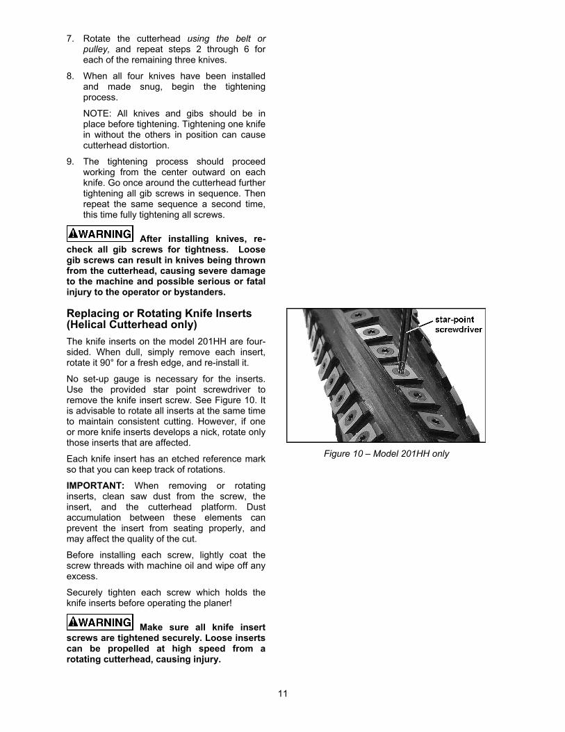
Replacing or Rotating Knife Inserts (Helical Cutterhead only)
The knife inserts on the model 201HH are four-sided. When dull, simply remove each insert, rotate it 90° for a fresh edge, and re-install it.
No set-up gauge is necessary for the inserts. Use the provided star point screwdriver to remove the knife insert screw. See Figure 10. It is advisable to rotate all inserts at the same time to maintain consistent cutting. However, if one or more knife inserts develops a nick, rotate only those inserts that are affected.
Each knife insert has an etched reference mark so that you can keep track of rotations.
IMPORTANT: When removing or rotating inserts, clean saw dust from the screw, the insert, and the cutterhead platform. Dust accumulation between these elements can prevent the insert from seating properly, and may affect the quality of the cut.
Before installing each screw, lightly coat the screw threads with machine oil and wipe off any excess.
Securely tighten each screw which holds the knife inserts before operating the planer!
Make sure all knife insert screws are tightened securely. Loose inserts can be propelled at high speed from a rotating cutterhead, causing injury.
Figure 10 – Model 201HH only
12
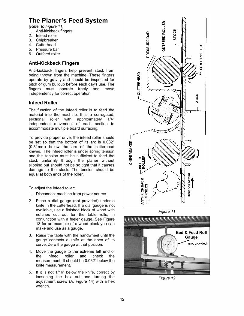
The Planer’s Feed System (Refer to Figure 11) 1. Anti-kickback fingers 2. Infeed roller 3. Chipbreaker 4. Cutterhead 5. Pressure bar 6. Outfeed roller
Anti-Kickback Fingers
Anti-kickback fingers help prevent stock from being thrown from the machine. These fingers operate by gravity and should be inspected for pitch or gum buildup before each day's use. The fingers must operate freely and move independently for correct operation.
Infeed Roller
The function of the infeed roller is to feed the material into the machine. It is a corrugated, sectional roller with approximately 1/4" independent movement of each section to accommodate multiple board surfacing. To provide proper drive, the infeed roller should be set so that the bottom of its arc is 0.032" (0.81mm) below the arc of the cutterhead knives. The infeed roller is under spring tension and this tension must be sufficient to feed the stock uniformly through the planer without slipping but should not be so tight that it causes damage to the stock. The tension should be equal at both ends of the roller. To adjust the infeed roller:
1. Disconnect machine from power source.
2. Place a dial gauge (not provided) under a knife in the cutterhead. If a dial gauge is not available, use a finished block of wood with notches cut out for the table rolls, in conjunction with a feeler gauge. See Figure 13 for an example of a wood block you can make and use as a gauge.
3. Raise the table with the handwheel until the gauge contacts a knife at the apex of its curve. Zero the gauge at that position.
4. Move the gauge to the extreme left end of the infeed roller and check the measurement. It should be 0.032” below the knife measurement.
5. If it is not 1/16” below the knife, correct by loosening the hex nut and turning the adjustment screw (A, Figure 14) with a hex wrench.
Figure 11
Figure 12

13
6. Move the gauge to the extreme right end of the infeed roller and check. Make similar adjustments if needed.
7. Tighten hex nuts (A, Figure 14) when finished.
IMPORTANT: The setting on both ends of the infeed roller must be the same to avoid skewing of the material as it is fed through the machine.
Chipbreaker
The chipbreaker is a sectionalized type made of spring-loaded sections mounted on a bar, which complements the sectional infeed roller. The functions of the chipbreaker are to break chips into small pieces, help avoid splintering of the wood, help avoid board bounce on thinner boards, to direct the flow of chips out of the machine, and to permit multiple board surfacing. The chipbreaker has been factory set at the same height as the cutting arc of the knives, and has been spring-tensioned properly.
A chipbreaker set too low or with excessive tension may prevent stock from feeding into the machine.
Pressure Bar
Most planing problems can be traced to improper setting of the pressure bar. Its function is to hold down the material after it passes under the cutterhead and throughout the remainder of the cut. Its basic setting is to be in line with the arc of the cutterhead knives.
If the pressure bar is too high, a shallow "clip" will occur at each end of the board. If it is too low, stock will not feed through.
Use a gauge to set the full length of the pressure bar to be 0.008" (0.20mm) above the arc of the cutterhead.
Figure 15 shows the height adjustment screw (C) and the spring tension adjustment screw (D) for the pressure bar. Loosen the hex nut and rotate the screw as needed. Make sure the setting on both ends of the pressure bar is the same. Tighten the hex nuts when adjustment is complete.
This initial setup is a starting point and final adjustment may have to be made during a test cut.
Figure 13
User-made Gauge Block
Figure 14
Figure 15

14
Outfeed Roller
The outfeed roller is of smooth, one-piece construction to help avoid marring the finished surface of the material being cut. It is spring tensioned, and its function is to continue to feed the material through the machine after it leaves the infeed roller. The correct free position setting is 0.032" (0.81mm) below the arc of the cutterhead knives. Use a gauge, such as a bed and feed roll gauge or wood gauge block (see Figure 13) to check the outfeed roller in the same manner as for the infeed roller. Adjust as necessary using the screws (E, Figure 15). When finished adjusting, tighten the hex nuts on the screws.
Table Rollers
The Planer has two table rollers which help reduce friction of the stock on the table as it feeds through the machine. It is not possible to give exact height setting of the table rollers because each type of wood behaves differently. As a general rule, however, the table rollers should be set high when planing rough stock, and set low for finish cuts.
The planer is equipped with a quick set table roller adjustment. With a single lever, you can raise the rolls from their finishing board height to a roughing board height. The range is 0.00 to 0.05”.
To adjust the height of the table rollers, loosen the handle (A, Figure 16) and move the quick-set lever (B, Figure 16) until the indicator is at the desired setting on the scale. Re-tighten the handle (A, Figure 16) to lock the setting.
NOTE: The handle (A) is adjustable. To re-position it, simply lift out on the handle, rotate it on the pin and release, making sure it seats itself properly on the pin.
The table rollers are adjusted at the factory. If they should need further or “fine” adjustment:
1. Disconnect machine from power source.
2. Loosen lock handle and position the quick-set lever (Figure 16) to zero.
3. Use a dial gauge (not provided) to find the distance from table top to the apex of the table roller. Zero the gauge at this position.
4. Place the gauge over the extreme right side of the table roller and find the high point of the table roller arc. The gauge should still read zero.
Figure 15 (repeated)
Figure 16

15
5. If the gauge reading is greater or less than zero, reach beneath the table with a wrench and loosen the hex nut (C, Figure 17) which is above the cam (D, Figure 17) near the end of the roller that needs adjusting. Rotate the hex cap screw (E, Figure 17) until the gauge reads zero.
6. Repeat the process for the left side of the table roller, and then re-check the right side. It is important that both ends of the table roller be the same height to help prevent skewing of the board as it feeds through the machine.
7. Re-tighten the hex nuts (C, Figure 17) on both ends of the table roller.
8. Repeat the procedure for the second table roller.
Table Adjustments
The planer table is raised and lowered by twin screws supported on bearings, and is guided by machined surfaces on the side panels. The fit-up to prevent the table from rocking is controlled by two gibs in front. See Figure 18. These gibs are pre-set at the factory and require no attention. If, after extensive use of the planer, some looseness in the table develops, these gibs can be adjusted individually using the gib screws provided so that the ways are lightly contacting on all four surfaces. The gibs should be tight enough to prevent rocking or movement of the table when the planer is in operation.
To perform accurate planing, the table must be parallel with the cutterhead. Lack of parallelism results in a taper over the width of the board. To check parallelism do the following:
1. Place a gauge on the table and contacting a knife at the apex of its arc. Do this at each end of the cutterhead and compare the measurements.
2. If the table is not parallel to the cutterhead, place the gauge at the end that needs to be raised.
3. Loosen the three socket head cap screws (A, Figure 19) beneath the table.
4. Place a rod-like object (such as a hex wrench) into one of the open holes (B, Figure 19) and turn the shaft (C, Figure 19) to raise the table until the gauge reads the proper measurement. Or, the same effect can be achieved by lowering the other side of the table.
5. Re-tighten the screws (A, Figure 19).
NOTE: This adjustment may generate the need to recalibrate the table height pointer.
Figure 17
Figure 18
Figure 19
16
Operating Controls The stop button is a mushroom style button which is convenient for “emergency” shutdowns. After being pushed, the stop button remains engaged. To re-start the planer, twist the stop button clockwise until it pops back out.
Test Cutting and Troubleshooting Using a piece of semi-finished stock, set up for a 1/16" (1.59mm) deep cut with the quick-set table roller adjustment (shown in Figure 16) set at zero. Start the machine and, standing to one side of the table, begin feeding the stock into the machine.
Never stand directly in line with stock or allow anyone else to do so, and do not bend down to see how stock is feeding. Should a kickback occur, serious or fatal injury could result.
The infeed roller should take the material and force it under the chipbreaker and cutterhead. If the material feeds through effortlessly, examine the finished cut carefully for imperfections. Learning to read a board for imperfections will save hours in adjusting a planer to operate properly.
Following are some problems that may arise and their probable remedies. The Figure illustrations are exaggerated for clarity. (Pages 19-21 also contain Troubleshooting remedies).
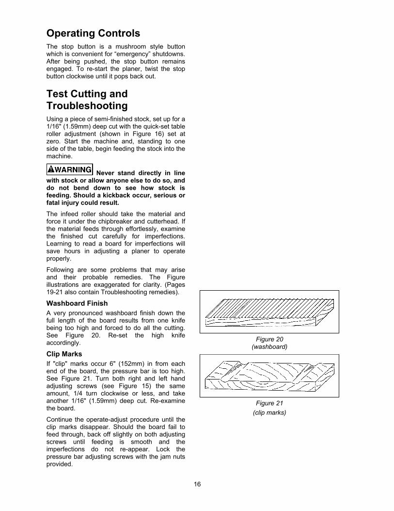
Washboard Finish A very pronounced washboard finish down the full length of the board results from one knife being too high and forced to do all the cutting. See Figure 20. Re-set the high knife accordingly.
Clip Marks If "clip" marks occur 6" (152mm) in from each end of the board, the pressure bar is too high. See Figure 21. Turn both right and left hand adjusting screws (see Figure 15) the same amount, 1/4 turn clockwise or less, and take another 1/16" (1.59mm) deep cut. Re-examine the board.
Continue the operate-adjust procedure until the clip marks disappear. Should the board fail to feed through, back off slightly on both adjusting screws until feeding is smooth and the imperfections do not re-appear. Lock the pressure bar adjusting screws with the jam nuts provided.
Figure 20
(washboard)
Figure 21
(clip marks)

17
Snipe Some amount of snipe may be inevitable with many planer operations, but proper planer adjustments can so minimize snipe as to make it negligible.
If noticeable snipes appear on each end of the material, as shown in Figure 22, a table roller is too high causing a slight lift of the material as it passes through the machine. Normally these snipes are more noticeable on the trailing end of the board than on the lead end, and most often occur during planing of rough lumber.
Table rollers must be elevated for running rough or resaw lumber through the machine. When material is turned over to surface the other side, and you neglect to lower the table rollers for a finish cut, then definite snipes will appear on the ends of the material.
Chatter Chatter marks usually appear on thin material. See Figure 23. Even at their lowest point, the table rollers are too high to handle thin material. Solve the problem by either using a slave board or making an auxiliary table out of Formica countertop material with cleating at each end to keep it stationary over the planer table.
Tapers If the machine planes a taper across the full width of the board, as shown in Figure 24, the table is not parallel with the cutterhead. First check that all knives are properly installed with equal protrusion from the cutterhead. If they are, then the table itself must be adjusted. See “Table Adjustments” on page 15.
Twisting If material twists while feeding through the planer, the pressure bar, outfeed roller or table rollers may be out of level. Refer to adjustment settings on pages 13 and 14.
Feed Restriction This is caused either by the table rollers being set too low for roughing operations or by a low pressure bar. About 90 percent of the time the pressure bar is too low. As the sharp edge of the planer knives wear, you must compensate for this wear by raising the pressure bar an equal amount on each side. Your first indication of knife wear is hesitation in feed of the material through the machine after it leaves the corrugated infeed roller on its way out of the machine. Disconnect machine from power and adjust the pressure bar acordingly. The material will free up and feed through smoothly when the planer is restarted.
Figure 22
(snipe)
Figure 23
(chatter)
Figure 24
(taper)

18
Never attempt pressure bar adjustment while planer is connected to power.
Feed restriction can also occur due to pitch buildup on the table. Be sure the table surface is clean. Occasionally dusting the surface with talc will aid in smoother feeding and help prevent pitch buildup.
Halted Feeding If the infeed roller takes the stock, the chipbreakers lift, and just as you hear the knives contact the material, it stops feeding, then the pressure bar is too low. Reset the pressure bar (see page 13).
Maintenance Periodic inspections are required to ensure that the machine is in proper adjustment, that all screws are tight, that belts are in good condition, that dust has not accumulated in the electrical enclosures, and that there are no loose or worn electrical connections.
Buildup of sawdust and other debris can cause your machine to plane inaccurately. Periodic cleaning is not only recommended but mandatory for accurate planing.
Close-fitting parts, such as the table locking rods, the cutterhead slot and gibs, should be cleaned with a cloth or brush and non-flammable solvent and freed from clinging foreign matter.
Use caution and proceed slowly when working with or around the cutterhead knives.
Remove resin and other accumulations from feed rolls and table with a non-flammable solvent.
Periodically check all the chains and belts for proper tension and adjust accordingly if required.
TIP: If a foreign object nicks the knives on the straight cutterhead (Model 201), instead of throwing them away or trying to grind out the deep nick, simply stagger the knives in the head, moving one knife no more than 1/4” to the right and another knife no more than 1/4” to the left. The nick will not be noticeable.
Lubrication
The gear box oil should be changed at least once a year. Remove the drain plug (A, Figure 25) to drain the oil into an appropriate container. Replace the drain plug and fill the gear box with 60 to 90 weight gear oil through the fill hole (B, Figure 25). Capacity is 0.494 gallon (1.87L). The sight glass (C, Figure 25) should be checked periodically and oil topped off as necessary.
Figure 25
The recommended lubrication for roller chains used in medium to slow speed operation is to simply wipe the chain clean. When there is an appreciable buildup of dust, dirt or wood shavings, use an oil cloth but never pour the oil directly on the chain. Over-oiling defeats the purpose of the lubrication, since it tends to invite the collection of dust, shavings, etc. and works into members of the chain. This hastens wear and leads to premature replacement.
The bearings on the cutterhead are factory lubricated and sealed. They require no further attention.
Periodically oil the bearings on the infeed and outfeed rollers, through the oil cups located on the bearing blocks (Figure 26).
Figure 26

19
Troubleshooting: Planer Operating Problems Trouble Probable Cause Remedy
Snipe.
Table rollers not set properly. Adjust table rollers to proper height.
Inadequate support of long boards. Support long boards with a roller stand.
Uneven feed roller pressure front to back.
Adjust feed roller tension.
Dull knives. Sharpen or replace knives.
Rotate or replace knife inserts.
Lumber not butted properly. Butt end-to-end each piece of stock as they pass through.
Fuzzy grain.
Planing wood with a high moisture content.
Remove moisture from wood by drying, or use different stock.
Dull knives. Sharpen or replace knives.
Rotate or replace knife inserts.
Torn grain.
Too heavy a cut. Adjust proper depth of cut.
Knives cutting against grain. Try to cut with the grain for finish cut.
Dull knives. Sharpen or replace knives.
Rotate or replace knife inserts.
Rough/raised grain.
Dull knives. Sharpen or replace knives.
Rotate or replace knife inserts.
Excessive depth of cut. Decrease cutting depth.
Moisture content too high. Remove moisture from wood by drying, or use different stock.
Rounded, glossy surface.
Dull knives. Sharpen or replace knives.
Rotate or replace knife inserts.
Poor feeding of lumber.
Inadequate feed roller pressure. Adjust feed roller tension. If proper tension cannot be achieved, replace feed roller(s).
Planer table rough or dirty. Clean off pitch and residue; apply light coat of paste wax to planer table.
Belts are slipping. Check belt tension and make any needed adjustments.
Surface of feed rollers has been worn too smooth.
Lightly roughen the feed roller surface with sandpaper.

20
Troubleshooting: Mechanical and Electrical Problems Trouble Probable Cause Remedy
Uneven depth of cut side to side.
Knives not set correctly. Make sure knives are set correctly and securely in cutterhead.
Planer table not parallel to cutterhead. Adjust table parallel to cutterhead. See page 15.
Board thickness does not match depth of cut scale.
Depth of cut scale is incorrect. Adjust pointer on depth of cut scale.
Chain is jumping.
Inadequate chain tension. Adjust chain tension.
Sprockets misaligned. Align sprockets.
Sprockets worn. Replace sprockets.
Machine will not start/restart or repeatedly trips circuit breaker or blows fuses.
No incoming power. Verify machine is connected to power.
Stop button is still engaged. Rotate stop button to disengage.
Overload automatic reset has not reset.
When the planer overloads on the circuit breaker built into the motor starter, it takes time for the machine to cool down before restart. Allow machine to adequately cool before attempting restart. If problem persists, check amp setting on the motor starter inside the electrical box.
Planer frequently trips.
One cause of overload trips which are not electrical in nature is too deep a cut. The solution is to take a lighter cut. If too deep a cut is not the problem, check the amp setting on the overload relay. Match the full load amps on the motor as noted on the motor plate.
If amp setting is correct, then there is probably a loose electrical lead or a failed component. See items below.
Building circuit breaker trips or fuse blows.
Verify that planer is on a circuit of correct size. If circuit size is correct, there is probably a loose electrical lead. Check amp setting on motor starter.
Loose electrical connections.
Go through all of the electrical connections on the planer including motor connections, verifying the tightness of each. Look for any signs of electrical arcing which is a sure indicator of loose connections or circuit overload.
21
Trouble Probable Cause Remedy
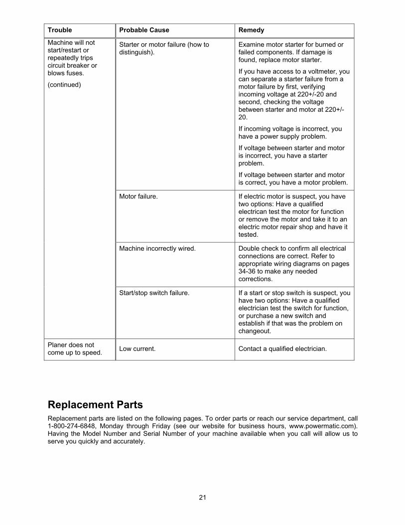
Machine will not start/restart or repeatedly trips circuit breaker or blows fuses.
(continued)
Starter or motor failure (how to distinguish).
Examine motor starter for burned or failed components. If damage is found, replace motor starter.
If you have access to a voltmeter, you can separate a starter failure from a motor failure by first, verifying incoming voltage at 220+/-20 and second, checking the voltage between starter and motor at 220+/-20.
If incoming voltage is incorrect, you have a power supply problem.
If voltage between starter and motor is incorrect, you have a starter problem.
If voltage between starter and motor is correct, you have a motor problem.
Motor failure. If electric motor is suspect, you have two options: Have a qualified electrican test the motor for function or remove the motor and take it to an electric motor repair shop and have it tested.
Machine incorrectly wired. Double check to confirm all electrical connections are correct. Refer to appropriate wiring diagrams on pages 34-36 to make any needed corrections.
Start/stop switch failure. If a start or stop switch is suspect, you have two options: Have a qualified electrician test the switch for function, or purchase a new switch and establish if that was the problem on changeout.
Planer does not come up to speed.
Low current. Contact a qualified electrician.
Replacement Parts Replacement parts are listed on the following pages. To order parts or reach our service department, call 1-800-274-6848, Monday through Friday (see our website for business hours, www.powermatic.com). Having the Model Number and Serial Number of your machine available when you call will allow us to serve you quickly and accurately.

22
Parts List: Base Assembly
Index No. Part No. Description Size Qty
1 ............... 6012068 ................... Rubber Boot ......................................................... .................................... 2 2 ............... 6012069 ................... Lead Screw .......................................................... .................................... 1 3 ............... 6293370 ................... Key ....................................................................... 5 x 5 x 10 .................... 2 4 ............... 6012070 ................... Screw w/ Washer............................M4x0.7Px8Lg / 4mmx10x0.8T .......... 4 5 ............... 6012071 ................... Bushing ................................................................ .................................... 2 6 ............... 6012072 ................... R-Ring .................................................................. RTW-68....................... 2 7 ............... 6012073 ................... Ball Bearing .......................................................... 6008-2NSE ................. 2 8 ............... 6012074 ................... Bearing ................................................................. 51105 .......................... 4 9 ............... 6012066 ................... Socket Head Cap Screw ...................................... M8 x 1.25P x 25Lg .... 11 10 ............. 6012075 ................... Bracket ................................................................. .................................... 2 11 ............. 6012076 ................... Sprocket ............................................................... .................................... 3 12 ............. 6012077 ................... Washer ................................................................. 25mm .......................... 2 13 ............. 6012078 ................... Nut ........................................................................ M25 x 1.5 .................... 2 14 ............. 6012079 ................... Hex Nut ............................................................... M10 x 1.5P .................. 5 15 ............. 6012080 ................... Flat Washer .......................................................... 10mm x 25 x 3T .......... 1 16 ............. 6012081 ................... Rocker Arm .......................................................... .................................... 1 17 ............. 6012082 ................... Shaft ..................................................................... .................................... 1 18 ............. 6012083 ................... Flat Washer .......................................................... 8.5mm x 19 x 2T ......... 2 19 ............. 6012067 ................... Spring Washer ..................................................... 8.2mm x 15.4 .............. 5 20 ............. 6012084 ................... Lead Screw .......................................................... .................................... 1
23
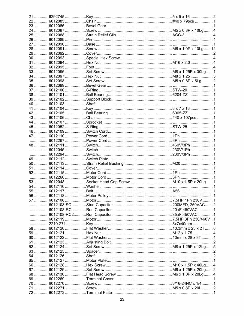
21 ............. 6292745 ................... Key ....................................................................... 5 x 5 x 16 .................... 2 22 ............. 6012085 ................... Chain .................................................................... #40 x 79pcs ................ 1 23 ............. 6012086 ................... Bevel Gear ........................................................... .................................... 1 24 ............. 6012087 ................... Screw ................................................................... M5 x 0.8P x 10Lg ........ 4 25 ............. 6012088 ................... Strain Relief Clip .................................................. ACC-3 ......................... 4 26 ............. 6012089 ................... Pin ........................................................................ .................................... 4 27 ............. 6012090 ................... Base ..................................................................... .................................... 1 28 ............. 6012091 ................... Screw ................................................................... M6 x 1.0P x 10Lg ...... 12 29 ............. 6012092 ................... Cover .................................................................... .................................... 2 30 ............. 6012093 ................... Special Hex Screw ............................................... .................................... 4 31 ............. 6012094 ................... Hex Nut ................................................................ M16 x 2.0 .................... 4 32 ............. 6012095 ................... Foot ...................................................................... .................................... 4 33 ............. 6012096 ................... Set Screw ............................................................. M8 x 1.25P x 30Lg ...... 1 34 ............. 6012097 ................... Hex Nut ................................................................ M8 x 1.25 .................... 3 35 ............. 6012098 ................... Set Screw ............................................................. M5 x 0.8P x 5Lg .......... 2 36 ............. 6012099 ................... Bevel Gear ........................................................... .................................... 1 37 ............. 6012100 ................... S-Ring .................................................................. STW-20 ....................... 1 38 ............. 6012101 ................... Ball Bearing .......................................................... 6204-ZZ ...................... 1 39 ............. 6012102 ................... Support Block ....................................................... .................................... 1 40 ............. 6012103 ................... Shaft ..................................................................... .................................... 1 41 ............. 6012104 ................... Key ....................................................................... 8 x 7 x 18 .................... 1 42 ............. 6012105 ................... Ball Bearing .......................................................... 6005-ZZ ...................... 1 43 ............. 6012106 ................... Chain .................................................................... #40 x 107pcs .............. 1 44 ............. 6012107 ................... Sprocket ............................................................... .................................... 1 45 ............. 6012052 ................... S-Ring .................................................................. STW-25 ....................... 1 46 ............. 6012109 ................... Switch Cord .......................................................... .................................... 1 47 ............. 6012110 ................... Power Cord .......................................................... 1Ph .............................. 1 ................. 6012267 ................... Power Cord .......................................................... 3Ph .............................. 1 48 ............. 6012111 ................... Switch ................................................................... 460V/3Ph .................... 1 ................. 6012045 ................... Switch ................................................................... 230V/1Ph .................... 1 ................. 6012294 ................... Switch ................................................................... 230V/3Ph .................... 1 49 ............. 6012112 ................... Switch Plate ......................................................... .................................... 1 50 ............. 6012113 ................... Strain Relief Bushing ........................................... M20 ............................. 1 51 ............. 6012114 ................... Cover .................................................................... .................................... 1 52 ............. 6012115 ................... Motor Cord ........................................................... 1Ph .............................. 1 ................. 6012266 ................... Motor Cord ........................................................... 3Ph .............................. 1 53 ............. 6012048 ................... Socket Head Cap Screw ...................................... M10 x 1.5P x 20Lg ...... 1 54 ............. 6012116 ................... Washer ................................................................. .................................... 1 55 ............. 6012117 ................... Belt ....................................................................... A56 .............................. 1 56 ............. 6012118 ................... Motor Pulley ......................................................... .................................... 1 57 ............. 6012108 ................... Motor .................................................................... 7.5HP 1Ph 230V ......... 1 ................. 6012108-SC ............. Start Capacitor ..................................................... 200MFD, 250VAC ....... 2 ................. 6012108-RC ............. Run Capacitor ...................................................... 20F,450VAC ............. 1 ................. 6012108-RC2 ........... Run Capacitor ...................................................... 35F,450VAC ............. 1 ................. 6012119 ................... Motor .................................................................... 7.5HP 3Ph 230/460V .. 1 ................. 2210-271 .................. Key ....................................................................... 8x7x40mm .................. 1 58 ............. 6012120 ................... Flat Washer .......................................................... 10.3mm x 23 x 2T ....... 8 59 ............. 6012121 ................... Hex Nut ................................................................ M12 x 1.75 .................. 4 60 ............. 6012122 ................... Flat Washer .......................................................... 13mm x 28 x 3T .......... 4 61 ............. 6012123 ................... Adjusting Bolt ....................................................... .................................... 2 62 ............. 6012124 ................... Set Screw ............................................................. M8 x 1.25P x 12Lg ...... 5 63 ............. 6012125 ................... Spacer .................................................................. .................................... 2 64 ............. 6012126 ................... Shaft ..................................................................... .................................... 2 65 ............. 6012127 ................... Motor Plate ........................................................... .................................... 1 66 ............. 6012128 ................... Hex Screw ............................................................ M10 x 1.5P x 40Lg ...... 4 67 ............. 6012129 ................... Set Screw ............................................................. M8 x 1.25P x 20Lg ...... 2 68 ............. 6012130 ................... Flat Head Screw .................................................. M6 x 1.0P x 20Lg ........ 4 69 ............. 6012269 ................... Terminal Cover .................................................... .................................... 1 70 ............. 6012270 ................... Screw ................................................................... 3/16-24NC x 1/4 .......... 1 71 ............. 6012271 ................... Screw ................................................................... M5 x 0.8P x 20L .......... 2 72 ............. 6012272 ................... Terminal Plate ...................................................... .................................... 1

24
Gearbox Assembly

25
Parts List: Gearbox Assembly
Index No. Part No. Description Size Qty
................. 201-100 .................... Gearbox Assembly ............................................... .................................... 1 1 ............... 6012034 ................... Gearbox Body ...................................................... .................................... 1 2 ............... 6012035 ................... Ball Bearing .......................................................... 6201-2NSE ................. 6 3 ............... 6012036 ................... S-Ring .................................................................. STW-16 ....................... 2 4 ............... 6012037 ................... Gear ..................................................................... .................................... 2 5 ............... 6012038 ................... Ball Bearing .......................................................... 6204-2NSE ................. 2 6 ............... 6012039 ................... Oil Seal ................................................................. TC24 x 40 x 8 ............. 1 7 ............... 6012040 ................... Shaft ..................................................................... .................................... 1 8 ............... 6293370 ................... Key ....................................................................... 5 x 5 x 10 .................... 4 9 ............... 6012041 ................... Gear ..................................................................... .................................... 2 10 ............. 6012042 ................... Gasket .................................................................. .................................... 1 11 ............. 6012043 ................... Pin ........................................................................ .................................... 4 12 ............. 6012044 ................... Gearbox Cover ..................................................... .................................... 1 13 ............. 6012142 ................... Hex Socket Cap Screw ........................................ M10 x 1.5P x 25Lg ...... 4 14 ............. 6012046 ................... Pulley ................................................................... .................................... 1 15 ............. 6012047 ................... Flat Washer .......................................................... 10mm x 25 x 3T .......... 2 16 ............. 6012048 ................... Socket Head Cap Screw ...................................... M10 x 1.5P x 20Lg ...... 1 17 ............. 6012049 ................... Socket Head Cap Screw ...................................... M8 x 1.25P x 20Lg ...... 1 18 ............. 6012050 ................... Sprocket ............................................................... .................................... 1 19 ............. 6292789 ................... Oil Plug ................................................................. PT1/4"-19UNF ............ 2 20 ............. 33-1051-00-1 ........... Oil Seal ................................................................. TC20 x 40 x 7 ............. 1 21 ............. 6012051 ................... Shaft ..................................................................... .................................... 1 22 ............. 6012052 ................... S-Ring .................................................................. STW-25 ....................... 1 23 ............. 6292745 ................... Key ....................................................................... 5 x 5 x 16 .................... 2 24 ............. 6012053 ................... Shaft ..................................................................... .................................... 1 25 ............. 6012054 ................... Gear ..................................................................... .................................... 1 26 ............. 6012055 ................... Shaft ..................................................................... .................................... 1 27 ............. 6012056 ................... Gear ..................................................................... .................................... 1 28 ............. 6012057 ................... Gear Assembly .................................................... .................................... 1 29 ............. 6012058 ................... Set Screw ............................................................. M5 x 0.8P x 5Lg .......... 1 30 ............. 6012059 ................... Spring Pin ............................................................. 4mm x 25Lg ................ 1 31 ............. 6012060 ................... Shift Fork .............................................................. .................................... 1 32 ............. 6012061 ................... Lever .................................................................... .................................... 1 33 ............. 6012062 ................... E-Ring .................................................................. ETW-12 ....................... 1 34 ............. 6012063 ................... Shift Shaft ............................................................. .................................... 1 35 ............. 6012064 ................... Eye Glass Oil Level .............................................. .................................... 1 36 ............. 6012065 ................... Spring Pin ............................................................. 5mm x 26Lg ................ 1 37 ............. 6012066 ................... Socket Head Cap Screw ...................................... M8 x 1.25P x 25Lg ...... 3 38 ............. 6012067 ................... Spring Washer ..................................................... 8.2mm x 15.4 .............. 4 39 ............. 6012082 ................... Shaft ..................................................................... .................................... 1 40 ............. 6012286 ................... Idle Sprocket ........................................................ .................................... 1 41 ............. 6012287 ................... Bracket ................................................................. .................................... 1 42 ............. 6012079 ................... Hex Nut ................................................................ M10 x 1.5P .................. 1 43 ............. 6012288 ................... Stand Off .............................................................. .................................... 1 44 ............. 6012289 ................... Check Nut ............................................................ M10 x 1.5P .................. 1 45 ............. 6012290 ................... E-Ring .................................................................. ETW-7 ......................... 1 46 ............. 6012291 ................... Spring ................................................................... .................................... 1 47 ............. 6012292 ................... Stand Off .............................................................. .................................... 1

26
Column Assembly

27
Parts List: Column Assembly
Index No. Part No. Description Size Qty
1 ............... 6012193 ................... Lifting Eye ............................................................ M20 x 2.5P x 30Lg ...... 2 2 ............... 6012194 ................... Left Column .......................................................... .................................... 1 3 ............... 6012195 ................... Pin ........................................................................ .................................... 4 4 ............... 6012079 ................... Hex Nut ................................................................ M10 x 1.5P .................. 1 5 ............... 6012080 ................... Flat Washer .......................................................... 10mm x 25 x 3T ........ 17 7 ............... 6012066 ................... Socket Head Cap Screw ...................................... M8 x 1.25P x 25Lg ...... 6 8 ............... 6012067 ................... Spring Washer ..................................................... 8.2mm x 15.4 .............. 7 9 ............... 6012083 ................... Flat Washer .......................................................... 8.5mm x 19 x 2T ......... 2 10 ............. 6012082 ................... Shaft ..................................................................... .................................... 1 11 ............. 6012197 ................... Sprocket ............................................................... .................................... 3 12 ............. 6012157 ................... Spring Washer ..................................................... 10.2mm x 18.4 .......... 16 13 ............. 6012198 ................... Socket Head Cap Screw ...................................... M10 x 1.5P x 40Lg ...... 2 14 ............. 6012199 ................... Pan Head Machine Screw ................................... M4 x 0.7P x 10Lg ........ 4 15 ............. 6012200 ................... Spring Washer ..................................................... 4.1mm x 7.7 ................ 4 16 ............. 6012201 ................... Flat Washer .......................................................... 4.3mm x 10 x 1T ......... 5 17 ............. 6012202 ................... Switch Box ........................................................... .................................... 2 18 ............. 6012203 ................... Left Sidecover ...................................................... .................................... 1 19 ............. 6012091 ................... Screw ................................................................... M6 x 1.0P x 10Lg ...... 16 20 ............. 6012204 ................... Hex Nut ................................................................ 5/16”-18NC ................. 1 21 ............. 6012205 ................... Idler Assembly ..................................................... .................................... 1 22 ............. 6012206 ................... Stand Off .............................................................. .................................... 2 23 ............. 6012207 ................... Stop Switch .......................................................... .................................... 1 24 ............. 6012208 ................... Start Switch .......................................................... .................................... 1 25 ............. 6012209 ................... Ball Detent ............................................................ 6mm ............................ 1 26 ............. 6012210 ................... Spring ................................................................... .................................... 1 27 ............. 6012211A ................. Shifter Hub ........................................................... .................................... 1 28 ............. 6012212 ................... Set Screw ............................................................. M6 x 1.0P x 12Lg ........ 1 29 ............. 6012213 ................... Shaft ..................................................................... .................................... 1 30 ............. 6012214 ................... Handle .................................................................. .................................... 1 31 ............. 6012087 ................... Screw ................................................................... M5 x 0.8P x 10Lg ........ 4 32 ............. 6012088 ................... Cord Clip .............................................................. ACC-3 ......................... 4 33 ............. 6012156 ................... Socket Head Cap Screw ...................................... M10 x 1.5P x 35Lg .... 14 34 ............. 6012215 ................... Right Column ....................................................... .................................... 1 35 ............. 6012216 ................... Ball Bearing .......................................................... 6004ZZ........................ 1 36 ............. 6293370 ................... Key ....................................................................... 5 x 5 x 10 .................... 1 37 ............. 6292745 ................... Key ....................................................................... 5 x 5 x 16 .................... 1 38 ............. 6012217 ................... Shaft ..................................................................... .................................... 1 39 ............. 6012218 ................... Housing ................................................................ .................................... 1 40 ............. 6012219 ................... Sleeve .................................................................. .................................... 1 41 ............. 6012220 ................... Socket Head Cap Screw ...................................... M6 x 1.0P x 16Lg ........ 2 42 ............. 6012221 ................... Rocker Arm .......................................................... .................................... 1 43 ............. 6012222 ................... Right Cover .......................................................... .................................... 1 44 ............. 6012223 ................... Handwheel ........................................................... .................................... 1 45 ............. 6012224 ................... Lock Knob ............................................................ .................................... 1 46 ............. 6012225 ................... Handwheel Swivel Assembly ............................... .................................... 1 47 ............. 6012226 ................... Label Shifter ......................................................... .................................... 1 48 ............. 6012227 ................... Rivet ..................................................................... .................................... 6 49 ............. 6012228 ................... Pointer .................................................................. .................................... 1 51 ............. 6012230 ................... Scale .................................................................... .................................... 1 52 ............. 6012293 ................... Hex Nut ................................................................ M20 x 2.5 .................... 1 53 ............. 6012231 ................... Height Adjust Label .............................................. .................................... 1 54 ............. 6012201 ................... Flat Washer .......................................................... 4.3 x 10 x 1T ............... 1 55 ............. 6012232 ................... Screw ................................................................... M4 x 0.7P x 8Lg .......... 1

28
Table Assembly
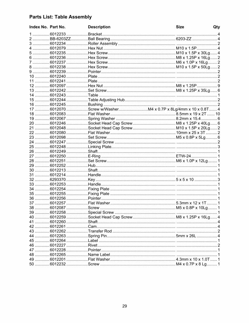
29
Parts List: Table Assembly
Index No. Part No. Description Size Qty
1 ............... 6012233 ................... Bracket ................................................................. .................................... 4 2 ............... BB-6203ZZ ............... Ball Bearing .......................................................... 6203-ZZ ...................... 4 3 ............... 6012234 ................... Roller Assembly ................................................... .................................... 2 4 ............... 6012079 ................... Hex Nut ................................................................ M10 x 1.5P .................. 4 5 ............... 6012235 ................... Hex Screw ............................................................ M10 x 1.5P x 30Lg ...... 4 6 ............... 6012236 ................... Hex Screw ............................................................ M8 x 1.25P x 16Lg ...... 2 7 ............... 6012237 ................... Hex Screw ............................................................ M6 x 1.0P x 16Lg ........ 2 8 ............... 6012238 ................... Hex Screw ............................................................ M10 x 1.5P x 50Lg ...... 2 9 ............... 6012239 ................... Pointer .................................................................. .................................... 2 10 ............. 6012240 ................... Plate ..................................................................... .................................... 2 11 ............. 6012241 ................... Plate ..................................................................... .................................... 2 12 ............. 6012097 ................... Hex Nut ................................................................ M8 x 1.25P .................. 9 13 ............. 6012242 ................... Set Screw ............................................................. M8 x 1.25P x 35Lg ...... 6 14 ............. 6012243 ................... Table .................................................................... .................................... 1 15 ............. 6012244 ................... Table Adjusting Hub ............................................. .................................... 2 16 ............. 6012245 ................... Bushing ................................................................ .................................... 2 17 ............. 6012070 ................... Screw w/Washer..........................M4 x 0.7P x 8Lg/4mm x 10 x 0.8T ....... 4 18 ............. 6012083 ................... Flat Washer .......................................................... 8.5mm x 19 x 2T ....... 10 19 ............. 6012067 ................... Spring Washer ..................................................... 8.2mm x 15.4 .............. 6 20 ............. 6012246 ................... Socket Head Cap Screw ...................................... M8 x 1.25P x 40Lg ...... 6 21 ............. 6012048 ................... Socket Head Cap Screw ...................................... M10 x 1.5P x 20Lg ...... 2 22 ............. 6012080 ................... Flat Washer .......................................................... 10mm x 25 x 3T .......... 2 23 ............. 6012098 ................... Set Screw ............................................................. M5 x 0.8P x 5Lg .......... 6 24 ............. 6012247 ................... Special Screw ...................................................... .................................... 2 25 ............. 6012248 ................... Linking Plate......................................................... .................................... 3 26 ............. 6012249 ................... Shaft ..................................................................... .................................... 1 27 ............. 6012250 ................... E-Ring .................................................................. ETW-24 ....................... 1 28 ............. 6012251 ................... Set Screw ............................................................. M6 x 1.0P x 12Lg ........ 1 29 ............. 6012252 ................... Hub ....................................................................... .................................... 1 30 ............. 6012213 ................... Shaft ..................................................................... .................................... 1 31 ............. 6012214 ................... Handle .................................................................. .................................... 1 32 ............. 6293370 ................... Key ....................................................................... 5 x 5 x 10 .................... 3 33 ............. 6012253 ................... Handle .................................................................. .................................... 1 34 ............. 6012254 ................... Fixing Plate .......................................................... .................................... 1 35 ............. 6012255 ................... Fixing Plate .......................................................... .................................... 1 36 ............. 6012256 ................... Pointer .................................................................. .................................... 1 37 ............. 6012257 ................... Flat Washer .......................................................... 5.3mm x 12 x 1T ......... 1 38 ............. 6012087 ................... Screw ................................................................... M5 x 0.8P x 10Lg ........ 1 39 ............. 6012258 ................... Special Screw ...................................................... .................................... 1 40 ............. 6012259 ................... Socket Head Cap Screw ...................................... M8 x 1.25P x 16Lg ...... 4 41 ............. 6012260 ................... Shaft ..................................................................... .................................... 4 42 ............. 6012261 ................... Cam ...................................................................... .................................... 4 43 ............. 6012262 ................... Transfer Rod ........................................................ .................................... 2 44 ............. 6012263 ................... Spring Pin ............................................................. 5mm x 26L .................. 4 45 ............. 6012264 ................... Label .................................................................... .................................... 1 46 ............. 6012227 ................... Rivet ..................................................................... .................................... 2 47 ............. 6012228 ................... Pointer .................................................................. .................................... 1 48 ............. 6012265 ................... Name Label .......................................................... .................................... 1 49 ............. 6012201 ................... Flat Washer .......................................................... 4.3mm x 10 x 1.0T ...... 1 50 ............. 6012232 ................... Screw ................................................................... M4 x 0.7P x 8 Lg ......... 1
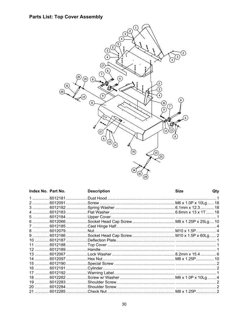
30
Parts List: Top Cover Assembly
Index No. Part No. Description Size Qty
1 ............... 6012181 ................... Dust Hood ............................................................ .................................... 1 2 ............... 6012091 ................... Screw ................................................................... M6 x 1.0P x 10Lg ...... 18 3 ............... 6012182 ................... Spring Washer ..................................................... 6.1mm x 12.3 ............ 18 4 ............... 6012183 ................... Flat Washer .......................................................... 6.6mm x 13 x 1T ....... 18 5 ............... 6012184 ................... Upper Cover ......................................................... .................................... 1 6 ............... 6012066 ................... Socket Head Cap Screw ...................................... M8 x 1.25P x 25Lg .... 10 7 ............... 6012185 ................... Cast Hinge Half .................................................... .................................... 4 8 ............... 6012079 ................... Nut ........................................................................ M10 x 1.5P .................. 4 9 ............... 6012186 ................... Socket Head Cap Screw ...................................... M10 x 1.5P x 60Lg ...... 2 10 ............. 6012187 ................... Deflection Plate .................................................... .................................... 1 11 ............. 6012188 ................... Top Cover ............................................................ .................................... 1 12 ............. 6012189 ................... Handle .................................................................. .................................... 1 13 ............. 6012067 ................... Lock Washer ........................................................ 8.2mm x 15.4 .............. 6 14 ............. 6012097 ................... Hex Nut ................................................................ M8 x 1.25P ................ 10 15 ............. 6012190 ................... Special Screw ...................................................... .................................... 2 16 ............. 6012191 ................... Cylinder ................................................................ .................................... 2 17 ............. 6012192 ................... Warning Label ...................................................... .................................... 1 18 ............. 6012282 ................... Screw w/ Washer ................................................. M6 x 1.0P x 10Lg ........ 4 19 ............. 6012283 ................... Shoulder Screw .................................................... .................................... 2 20 ............. 6012284 ................... Shoulder Screw .................................................... .................................... 2 21 ............. 6012285 ................... Check Nut ............................................................ M8 x 1.25P .................. 2
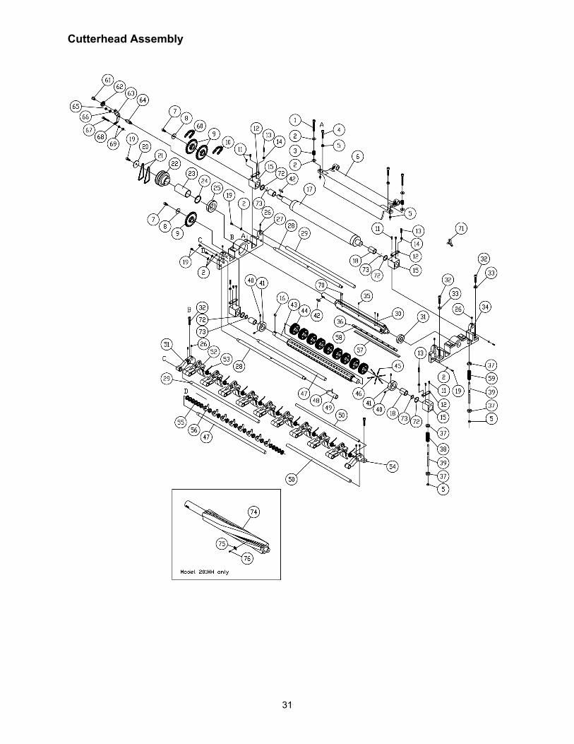
31
Cutterhead Assembly
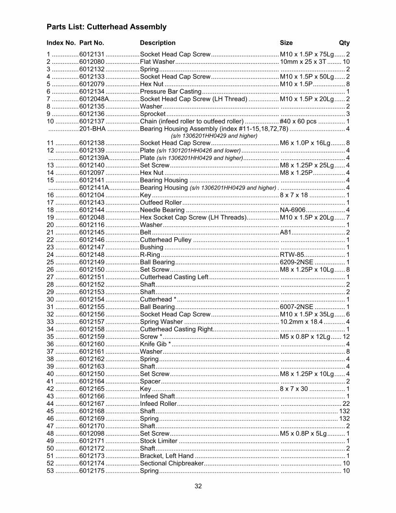
32
Parts List: Cutterhead Assembly
Index No. Part No. Description Size Qty
1 ............... 6012131 ................... Socket Head Cap Screw ...................................... M10 x 1.5P x 75Lg ...... 2 2 ............... 6012080 ................... Flat Washer .......................................................... 10mm x 25 x 3T ........ 10 3 ............... 6012132 ................... Spring ................................................................... .................................... 2 4 ............... 6012133 ................... Socket Head Cap Screw ...................................... M10 x 1.5P x 50Lg ...... 2 5 ............... 6012079 ................... Hex Nut ................................................................ M10 x 1.5P .................. 8 6 ............... 6012134 ................... Pressure Bar Casting ........................................... .................................... 1 7 ............... 6012048A ................. Socket Head Cap Screw (LH Thread) ................. M10 x 1.5P x 20Lg ...... 2 8 ............... 6012135 ................... Washer ................................................................. .................................... 2 9 ............... 6012136 ................... Sprocket ............................................................... .................................... 3 10 ............. 6012137 ................... Chain (infeed roller to outfeed roller) ................... #40 x 60 pcs ............... 1 ................. 201-BHA .................. Bearing Housing Assembly (index #11-15,18,72,78) ............................... 4 (s/n 1306201HH0429 and higher) 11 ............. 6012138 ................... Socket Head Cap Screw ...................................... M6 x 1.0P x 16Lg ........ 8 12 ............. 6012139 ................... Plate (s/n 1301201HH0426 and lower) ..................... .................................... 4 ................. 6012139A ................. Plate (s/n 1306201HH0429 and higher) .................... .................................... 4 13 ............. 6012140 ................... Set Screw ............................................................. M8 x 1.25P x 25Lg ...... 4 14 ............. 6012097 ................... Hex Nut ................................................................ M8 x 1.25P .................. 4 15 ............. 6012141 ................... Bearing Housing .................................................. .................................... 4 ................. 6012141A ................. Bearing Housing (s/n 1306201HH0429 and higher) . .................................... 4 16 ............. 6012104 ................... Key ....................................................................... 8 x 7 x 18 .................... 1 17 ............. 6012143 ................... Outfeed Roller ...................................................... .................................... 1 18 ............. 6012144 ................... Needle Bearing .................................................... NA-6906 ...................... 4 19 ............. 6012048 ................... Hex Socket Cap Screw (LH Threads) .................. M10 x 1.5P x 20Lg ...... 7 20 ............. 6012116 ................... Washer ................................................................. .................................... 1 21 ............. 6012145 ................... Belt ....................................................................... A81 .............................. 2 22 ............. 6012146 ................... Cutterhead Pulley ................................................ .................................... 1 23 ............. 6012147 ................... Bushing ................................................................ .................................... 1 24 ............. 6012148 ................... R-Ring .................................................................. RTW-85....................... 1 25 ............. 6012149 ................... Ball Bearing .......................................................... 6209-2NSE ................. 1 26 ............. 6012150 ................... Set Screw ............................................................. M8 x 1.25P x 10Lg ...... 8 27 ............. 6012151 ................... Cutterhead Casting Left ....................................... .................................... 1 28 ............. 6012152 ................... Shaft ..................................................................... .................................... 2 29 ............. 6012153 ................... Shaft ..................................................................... .................................... 2 30 ............. 6012154 ................... Cutterhead * ......................................................... .................................... 1 31 ............. 6012155 ................... Ball Bearing .......................................................... 6007-2NSE ................. 1 32 ............. 6012156 ................... Socket Head Cap Screw ...................................... M10 x 1.5P x 35Lg ...... 6 33 ............. 6012157 ................... Spring Washer ..................................................... 10.2mm x 18.4 ............ 4 34 ............. 6012158 ................... Cutterhead Casting Right ..................................... .................................... 1 35 ............. 6012159 ................... Screw * ................................................................. M5 x 0.8P x 12Lg ...... 12 36 ............. 6012160 ................... Knife Gib * ............................................................ .................................... 4 37 ............. 6012161 ................... Washer ................................................................. .................................... 8 38 ............. 6012162 ................... Spring ................................................................... .................................... 4 39 ............. 6012163 ................... Shaft ..................................................................... .................................... 4 40 ............. 6012150 ................... Set Screw ............................................................. M8 x 1.25P x 10Lg ...... 4 41 ............. 6012164 ................... Spacer .................................................................. .................................... 2 42 ............. 6012165 ................... Key ....................................................................... 8 x 7 x 30 .................... 1 43 ............. 6012166 ................... Infeed Shaft .......................................................... .................................... 1 44 ............. 6012167 ................... Infeed Roller ......................................................... .................................. 22 45 ............. 6012168 ................... Shaft ..................................................................... ................................ 132 46 ............. 6012169 ................... Spring ................................................................... ................................ 132 47 ............. 6012170 ................... Shaft ..................................................................... .................................... 2 48 ............. 6012098 ................... Set Screw ............................................................. M5 x 0.8P x 5Lg .......... 1 49 ............. 6012171 ................... Stock Limiter ........................................................ .................................... 1 50 ............. 6012172 ................... Shaft ..................................................................... .................................... 2 51 ............. 6012173 ................... Bracket, Left Hand ............................................... .................................... 1 52 ............. 6012174 ................... Sectional Chipbreaker .......................................... .................................. 10 53 ............. 6012175 ................... Spring ................................................................... .................................. 10
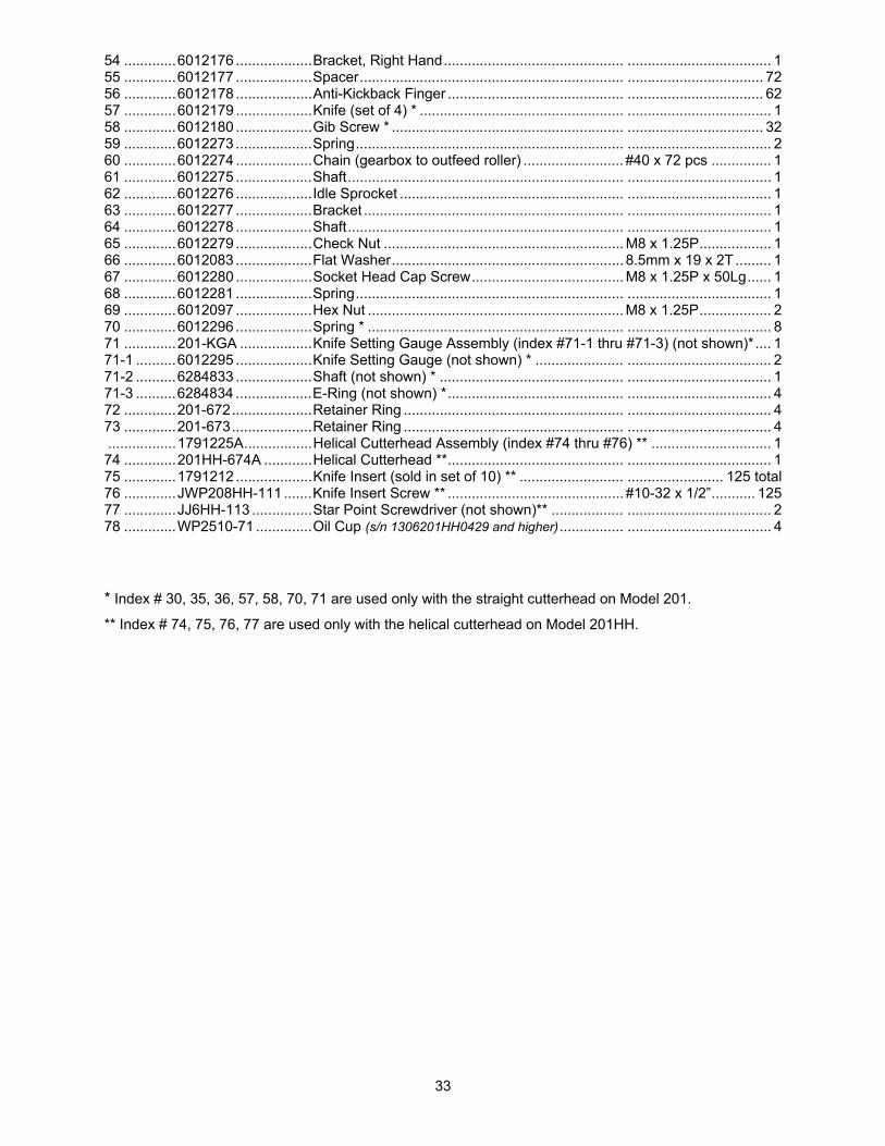
33
54 ............. 6012176 ................... Bracket, Right Hand ............................................. .................................... 1 55 ............. 6012177 ................... Spacer .................................................................. .................................. 72 56 ............. 6012178 ................... Anti-Kickback Finger ............................................ .................................. 62 57 ............. 6012179 ................... Knife (set of 4) * ................................................... .................................... 1 58 ............. 6012180 ................... Gib Screw * .......................................................... .................................. 32 59 ............. 6012273 ................... Spring ................................................................... .................................... 2 60 ............. 6012274 ................... Chain (gearbox to outfeed roller) ......................... #40 x 72 pcs ............... 1 61 ............. 6012275 ................... Shaft ..................................................................... .................................... 1 62 ............. 6012276 ................... Idle Sprocket ........................................................ .................................... 1 63 ............. 6012277 ................... Bracket ................................................................. .................................... 1 64 ............. 6012278 ................... Shaft ..................................................................... .................................... 1 65 ............. 6012279 ................... Check Nut ............................................................ M8 x 1.25P .................. 1 66 ............. 6012083 ................... Flat Washer .......................................................... 8.5mm x 19 x 2T ......... 1 67 ............. 6012280 ................... Socket Head Cap Screw ...................................... M8 x 1.25P x 50Lg ...... 1 68 ............. 6012281 ................... Spring ................................................................... .................................... 1 69 ............. 6012097 ................... Hex Nut ................................................................ M8 x 1.25P .................. 2 70 ............. 6012296 ................... Spring * ................................................................ .................................... 8 71 ............. 201-KGA .................. Knife Setting Gauge Assembly (index #71-1 thru #71-3) (not shown)* .... 1 71-1 .......... 6012295 ................... Knife Setting Gauge (not shown) * ...................... .................................... 2 71-2 .......... 6284833 ................... Shaft (not shown) * .............................................. .................................... 1 71-3 .......... 6284834 ................... E-Ring (not shown) * ............................................ .................................... 4 72 ............. 201-672 .................... Retainer Ring ....................................................... .................................... 4 73 ............. 201-673 .................... Retainer Ring ....................................................... .................................... 4 ................. 1791225A ................. Helical Cutterhead Assembly (index #74 thru #76) ** .............................. 1 74 ............. 201HH-674A ............ Helical Cutterhead ** ............................................ .................................... 1 75 ............. 1791212 ................... Knife Insert (sold in set of 10) ** .......................... ........................ 125 total 76 ............. JWP208HH-111 ....... Knife Insert Screw ** ............................................ #10-32 x 1/2” ........... 125 77 ............. JJ6HH-113 ............... Star Point Screwdriver (not shown)** .................. .................................... 2 78 ............. WP2510-71 .............. Oil Cup (s/n 1306201HH0429 and higher) ................ .................................... 4
* Index # 30, 35, 36, 57, 58, 70, 71 are used only with the straight cutterhead on Model 201.
** Index # 74, 75, 76, 77 are used only with the helical cutterhead on Model 201HH.
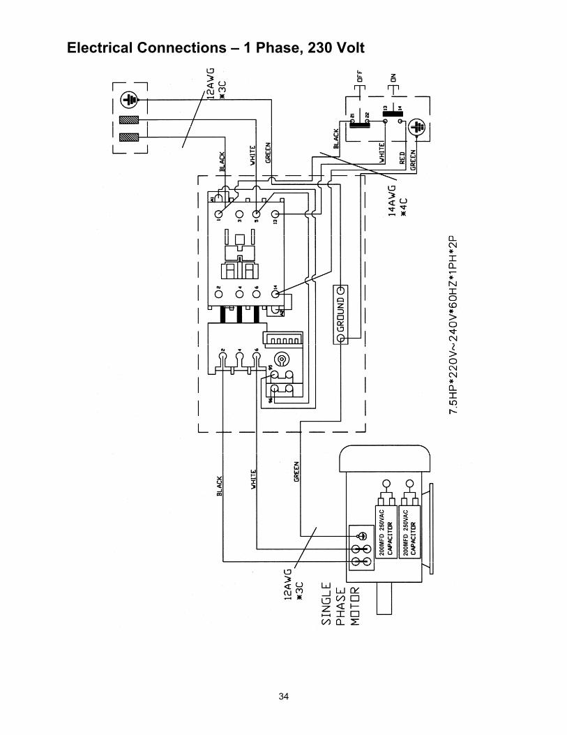
34
Electrical Connections – 1 Phase, 230 Volt

35
Electrical Connections – 3 Phase, 230 Volt

36
427 New Sanford Road LaVergne, Tennessee 37086
Phone: 800-274-6848 www.powermatic.com