Embed Size (px)
Citation preview

This Manual is Bookmarked
C US
R
108026
WMH TOOL GROUP, Inc.427 New Sanford RoadLaVergne, Tennessee 30786 Part No. M-414500Ph.: 800-274-6848 Revision A1 03/09www.wmhtoolgroup.com Copyright © 2009 WMH Tool Group, Inc.
Operating Instructions and Parts Manual14-Inch Vertical Band SawsModels: J-8201, J-8203K, J-8201VS, J-8203VS
Model J-8201 shown

Warranty and ServiceWMH Tool Group, Inc., warrants every product it sells. If one of our tools needs service or repair, one of our AuthorizedService Centers located throughout the United States can give you quick service. In most cases, any of these WMH ToolGroup Authorized Service Centers can authorize warranty repair, assist you in obtaining parts, or perform routine maintenanceand major repair on your JET® tools. For the name of an Authorized Service Center in your area call 1-800-274-6848.MORE INFORMATIONWMH Tool Group is consistently adding new products to the line. For complete, up-to-date product information, check withyour local WMH Tool Group distributor, or visit jettools.com.WARRANTYJET products carry a limited warranty which varies in duration based upon the product (MW stands for Metalworking, WWstands for Woodworking).
WHAT IS COVERED?This warranty covers any defects in workmanship or materials subject to the exceptions stated below. Cutting tools,abrasives and other consumables are excluded from warranty coverage.WHO IS COVERED?This warranty covers only the initial purchaser of the product.WHAT IS THE PERIOD OF COVERAGE?The general JET warranty lasts for the time period specified in the product literature of each product.WHAT IS NOT COVERED?Three Year, Five Year and Lifetime Warranties do not cover products used for industrial or educational purposes.Products with Three Year, Five Year or Lifetime Warranties that are used for industrial or education purposes revert to aOne Year Warranty. This warranty does not cover defects due directly or indirectly to misuse, abuse, negligence oraccidents, normal wear-and-tear, improper repair or alterations, or lack of maintenance.HOW TO GET SERVICEThe product or part must be returned for examination, postage prepaid, to a location designated by us. For the name ofthe location nearest you, please call 1-800-274-6848.You must provide proof of initial purchase date and an explanation of the complaint must accompany the merchandise.If our inspection discloses a defect, we will repair or replace the product, or refund the purchase price, at our option. Wewill return the repaired product or replacement at our expense unless it is determined by us that there is no defect, or thatthe defect resulted from causes not within the scope of our warranty in which case we will, at your direction, dispose ofor return the product. In the event you choose to have the product returned, you will be responsible for the shipping andhandling costs of the return.HOW STATE LAW APPLIESThis warranty gives you specific legal rights; you may also have other rights which vary from state to state.LIMITATIONS ON THIS WARRANTYWMH TOOL GROUP LIMITS ALL IMPLIED WARRANTIES TO THE PERIOD OF THE LIMITED WARRANTY FOR EACHPRODUCT. EXCEPT AS STATED HEREIN, ANY IMPLIED WARRANTIES OR MERCHANTABILITY AND FITNESS AREEXCLUDED. SOME STATES DO NOT ALLOW LIMITATIONS ON HOW LONG THE IMPLIED WARRANTY LASTS, SO THEABOVE LIMITATION MAY NOT APPLY TO YOU.WMH TOOL GROUP SHALL IN NO EVENT BE LIABLE FOR DEATH, INJURIES TO PERSONS OR PROPERTY, OR FORINCIDENTAL, CONTINGENT, SPECIAL, OR CONSEQUENTIAL DAMAGES ARISING FROM THE USE OF OUR PRODUCTS.SOME STATES DO NOT ALLOW THE EXCLUSION OR LIMITATION OF INCIDENTAL OR CONSEQUENTIAL DAMAGES,SO THE ABOVE LIMITATION OR EXCLUSION MAY NOT APPLY TO YOU.WMH Tool Group sells through distributors only. The specifications in WMH catalogs are given as general informationand are not binding. Members of WMH Tool Group reserve the right to effect at any time, without prior notice, thosealterations to parts, fittings, and accessory equipment which they may deem necessary for any reason whatsoever. JET®
branded products are not sold in Canada by WMH Tool Group.
YEARYEARDAYDAY WARRANTY
WARRANTY
9090
WARRANTY
WARRANTY
1YEARYEAR W
ARRANTY
WARRANTY
5LIFETIMELIFETIME W
ARRANTY
WARRANTY
LIFELIFEYEARYEAR W
ARRANTY
WARRANTY
2YEARYEAR W
ARRANTY
WARRANTY
3Lathe AccessoriesMachine AccessoriesMobile BasesSafety EquipmentSpecialty ItemsVise Accessories
Air Tools- ContractorAir Tools-IndustrialAir Tools-Light IndustrialLubrication
Fastening ToolsMechanics Hand ToolsStriking ToolsVises (no -precision)Clamps
Palet TrucksRigging Equip.Service JacksStackersSurface GrindersTappingTrolleys-AirTrolleys-ElectricWeb SlingsWinches-Electric
Body Repair KitsBottle JacksCable PullersCold SawsHoists-AirHoists-ElectricMetal formingMill/DrillsMilling Machines
MW Precision Vises
MW BandsawsMW Drill PressesMW Finishing EquipmentMW Lathes
Beam ClampsChain Hoist- ManualLever HoistsPullers-JCH ModelsScissor Lift TablesScrew JacksTrolleys-GearedTrolleys-PlainWinches-ManualWW Air FiltrationWW BandsawsWW Buffers
WW Drill PressesWW Dust CollectorsWW Dust FiltersWW Dust FittingsWW JointersWW LathesWW PlanersWW Sanders
WW ShapersWW Tablesaws
WW Benchtop Tools
Warranty reverts to 1 Year Warranty if woodworking (WW) products listed above are used for industrial or educational purposes.
3
Table of ContentsCover Page.................................................................................................. 1General Specifications ................................................................................ 4Warnings and Safety ................................................................................... 5Set-up and Operation.................................................................................. 8Operating Instructions ............................................................................... 13Maintenance .............................................................................................. 17Troubleshooting ........................................................................................ 19Replacement Parts ................................................................................... 22Wiring Diagram
4
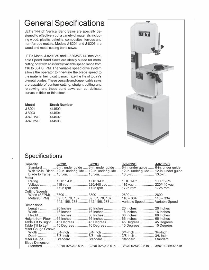
JET’s 14-inch Vertical Band Saws are specially de-signed to effectively cut a variety of materials includ-ing wood, plastic, bakelite, composites, ferrous andnon-ferrous metals. Models J-8201 and J-8203 arewood and metal cutting band saws.
JET’s Model J-8201VS and J-8203VS 14-inch Vari-able Speed Band Saws are ideally suited for metalcutting only with an infinitely variable speed range from116 to 334 SFPM. The variable speed drive systemallows the operator to fine-tune the blade speed tothe material being cut to maximize the life of today’sbi-metal blades. These versatile and dependable sawsare capable of contour cutting, straight cutting andre-sawing, and these band saws can cut delicatecurves in thick or thin stock.
General Specifications
Capacity J-8201 J-8203 J-8201VS J-8203VSStandard ..............6-in. under guide ..... 6-in. under guide ....... 6-in. under guide ...... 6-in. under guideWith 12-in. Riser ..12-in. under guide ... 12-in. under guide ..... 12-in. under guide .... 12-in. under guideBlade to frame .....13.5-in. .................... 13.5-in. ..................... 13.5-in. ..................... 13.5-in.
MotorRating ..................1 HP 1-Ph ............... 1 HP 3-Ph ................. 1 HP 1-Ph ................ 1 HP 3-PhVoltage.................115 vac .................... 220/440 vac .............. 115 vac .................... 220/440 vacSpeed ..................1725 rpm ................. 1725 rpm .................. 1725 rpm.................. 1725 rpm
Cutting SpeedsWood (SFPM) ......3300 ........................ 3300 ......................... 2600 ......................... 2600Metal (SFPM) .......39, 57, 78, 107, ....... 39, 57, 78, 107, ........ 116 – 334 ................. 116 – 334
142, 196, 278 .......... 142, 196, 278 ............ Variable Speed ......... Variable SpeedDimensions
Length .................20 Inches ................ 20 Inches .................. 20 Inches ................. 20 InchesWidth ...................16 Inches ................ 16 Inches .................. 16 Inches ................. 16 InchesHeight ..................66 Inches ................ 66 Inches .................. 66 Inches ................. 66 Inches
Height from Floor .....66 Inches ................ 66 Inches .................. 66 Inches ................. 66 InchesTable Tilt to Right .....45 Degrees ............. 45 Degrees ............... 45 Degrees .............. 45 DegreesTable Tilt to Left .......10 Degrees ............. 10 Degrees ............... 10 Degrees .............. 10 DegreesMiter Gauge Groove
Width ...................3/4-Inch ................... 3/4-Inch .................... 3/4-Inch .................... 3/4-InchDepth ...................3/8-Inch ................... 3/8-Inch .................... 3/8-Inch .................... 3/8-Inch
Miter Gauge .............Standard .................. Standard ................... Standard .................. StandardBlade Dimension
Standard ..............3/8x0.025x92.5 In. ... 3/8x0.025x92.5 In. .... 3/8x0.025x92.5 In. ... 3/8x0.025x92.5 In.
Specifications
Model Stock NumberJ-8201 414500J-8203 414504J-8201VS 414502J-8203VS 414503
5
cal supply while servicing.- Always follow instructions in Operating Instruc- tions and Parts Manual when changing acces- sory tools or parts.- Never modify the machine without consulting JETCorporation.You - the Stationary Power Tool User - Holdthe Key to Safety.
Read and follow these simple rules for best results andfull benefits from your machine. Used properly, JET’smachinery is among the best in design and safety.However, any machine used improperly can be renderedinefficient and unsafe. It is absolutely mandatory thatthose who use our products be properly trained in how touse them correctly. They should read and understandthe Operating Instructions and Parts Manual as well asall labels affixed to the machine. Failure to follow all ofthese warnings can cause serious injuries.
WARNING: For your own safety read instruction manual beforeoperating band saw.
- Misuse of this machine can cause serious injury.- For safety, machine must be set up, used andserviced properly.- Read, understand and follow instructions in theOperating Instructions and Parts Manual whichwas shipped with your machine.When Setting up Machine:- Always avoid using machine in damp or poorly
lighted work areas.- Always be sure the machine support is se- curely anchored to the floor or the work bench.When Using Machine:- Always wear safety glasses with side shields (See ANSI Z87.1)- Never wear loose clothing or jewelry.- Never overreach - you may slip and fall.When Servicing Machine:- Always disconnect the machine from its electri-
1. KEEP GUARDS IN PLACE and in working order.2. REMOVE ADJUSTING KEYS AND WRENCHES.Form habit of checking to see that keys and adjust-ing wrenches are removed from tool before turning iton.3. KEEP WORK AREA CLEAN. Cluttered areas andbenches invite accidents.4. DON’T USE IN DANGEROUS ENVIRONMENT.Don’t use power tools in damp or wet locations, orexpose them to rain. Keep work area well lighted.5. KEEP CHILDREN AWAY. All visitors should be keptsafe distance from work area.6. MAKE WORKSHOP KID PROOF with padlocks,master switches, or by removing starter keys.7. DON’T FORCE TOOL It will do the job better andsafer at the rate for which it was designed.8. USE RIGHT TOOL Don’t force tool or attachmentto do a job for which it was not designed.9. USE PROPER EXTENSION CORD. Make sure yourextension cord is in good condition. When using anextension cord, be sure to use one heavy enough tocarry the current your product will draw. An under-sized cord will cause a drop in line voltage resulting inloss of power and overheating. Table 1 shows the cor-rect size to use depending on cord length and name-plate ampere rating. If in doubt, use the next heaviergage. The smaller the gage number, the heavier thecord.10. WEAR PROPER APPAREL Do not wear looseclothing, gloves, neckties, rings, bracelets, or other
jewelry which may get caught in moving parts. Non-slip footwear is recommended. Wear protective haircovering to contain long hair.11. WEAR EYE PROTECTION. Always use safetyglasses. Also use face or dust mask if cutting opera-tion is dusty. Everyday eyeglasses only have impactresistant lenses, they are NOT safety glasses.12. SECURE WORK. Use clamps or a vise to holdwork when practical. It’s safer than using your handand it frees both hands to operate tool.13. DON’T OVERREACH. Keep proper footing andbalance at all times.14. MAINTAIN TOOLS WITH CARE. Keep tools sharpand clean for best and safest performance. Followinstructions for lubricating and changing accessories.15. DISCONNECT TOOLS before servicing; whenchanging accessories, such as blades, bits, cutters,and the like.16. REDUCE THE RISK OF UNINTENTIONAL START-ING. Make sure switch is in off position before plug-ging in.17. USE RECOMMENDED ACCESSORIES. Con-sult the owner’s manual for recommended accesso-ries. The use of improper accessories may cause riskof injury to persons.18. NEVER STAND ON TOOL Serious injury couldoccur if the tool is tipped or if the cutting tool is unin-tentionally contacted.19. CHECK DAMAGED PARTS. Before further use ofthe tool, a guard or other part that is damaged should
6
General Electrical CautionsThis saw should be grounded in accordance with
the National Electrical Code and local codes and or-dinances. This work should be done by a qualifiedelectrician. The saw should be grounded to protectthe user from electrical shock.
Caution: For circuits which are far away from theelectrical service box, the wire size must be increasedin order to deliver ample voltage to the motor. To mini-mize power losses and to prevent motor overheatingand burnout, the use of wire sizes for branch circuitsor electrical extension cords according to the follow-ing table is recommended.
be carefully checked to determine that it will operateproperly and perform its intended function - check foralignment of moving parts, binding of moving parts,breakage of parts, mounting, and any other condi-tions that may affect its operation.A guard or other part that is damaged should be prop-erly repaired or replaced.20. DIRECTION OF FEED. Feed work into a blade orcutter against the direction of rotation of the blade orcutter only.21. NEVER LEAVE TOOL RUNNING UNATTENDED.TURN POWER OFF. Don’t leave tool until it comesto a complete stop.22. DO NOT REMOVE JAMMED CUTOFF PIECESuntil the blade has stopped.23. MAINTAIN PROPER ADJUSTMENT of blade ten-sion, blade guides and thrust bearings.24. ADJUST UPPER BLADE GUIDE TO JUST CLEARWORKPIECE.25. HOLD WORKPIECE FIRMLY AGAINST TABLE.
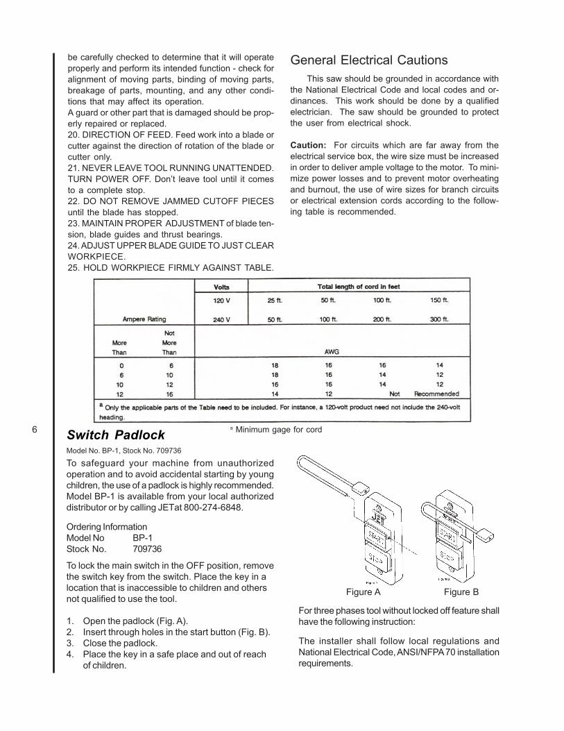
a Minimum gage for cordSwitch PadlockModel No. BP-1, Stock No. 709736
To safeguard your machine from unauthorizedoperation and to avoid accidental starting by youngchildren, the use of a padlock is highly recommended.Model BP-1 is available from your local authorizeddistributor or by calling JETat 800-274-6848.
Ordering InformationModel No BP-1Stock No. 709736
To lock the main switch in the OFF position, removethe switch key from the switch. Place the key in alocation that is inaccessible to children and othersnot qualified to use the tool.
1. Open the padlock (Fig. A).2. Insert through holes in the start button (Fig. B).3. Close the padlock.4. Place the key in a safe place and out of reach
of children.
For three phases tool without locked off feature shallhave the following instruction:
The installer shall follow local regulations andNational Electrical Code, ANSI/NFPA 70 installationrequirements.
Figure A Figure B
7
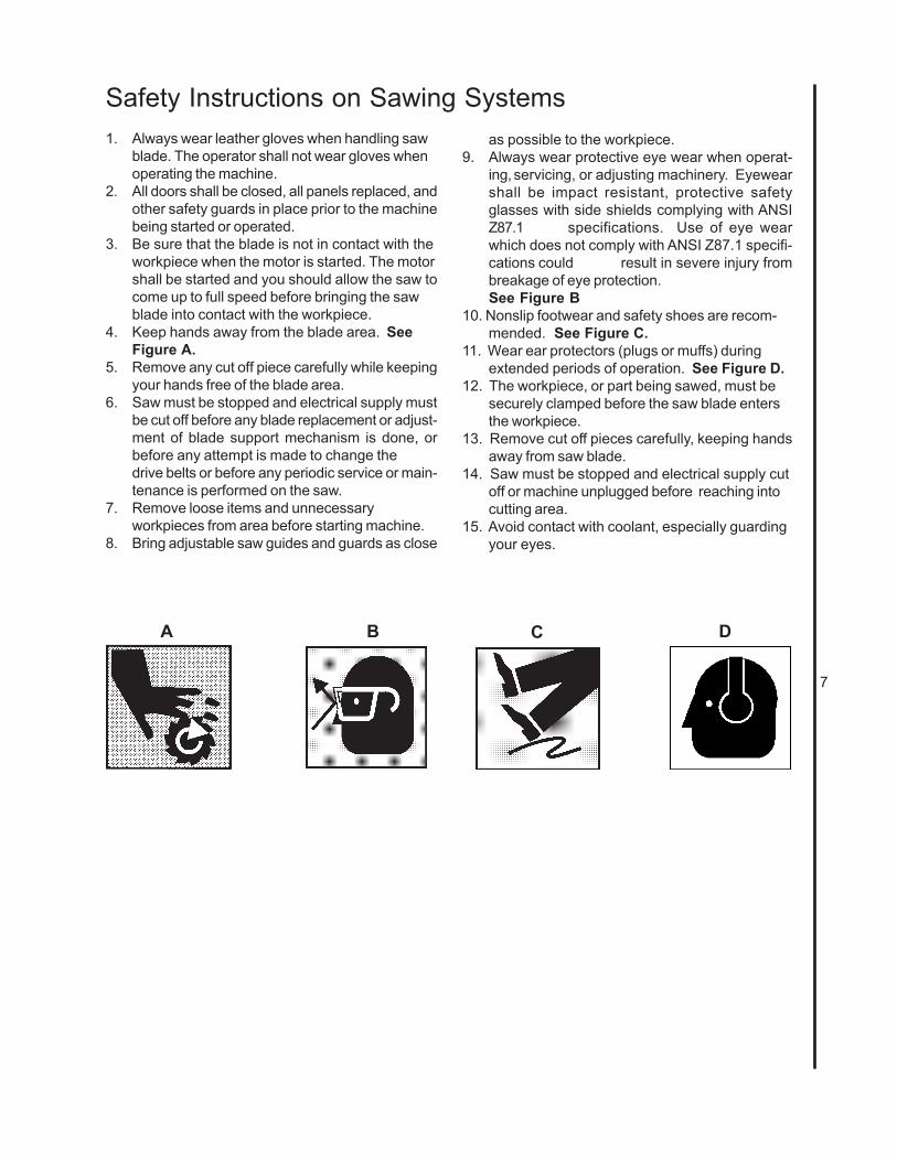
1. Always wear leather gloves when handling sawblade. The operator shall not wear gloves whenoperating the machine.
2. All doors shall be closed, all panels replaced, andother safety guards in place prior to the machinebeing started or operated.
3. Be sure that the blade is not in contact with theworkpiece when the motor is started. The motorshall be started and you should allow the saw tocome up to full speed before bringing the sawblade into contact with the workpiece.
4. Keep hands away from the blade area. SeeFigure A.
5. Remove any cut off piece carefully while keepingyour hands free of the blade area.
6. Saw must be stopped and electrical supply mustbe cut off before any blade replacement or adjust-ment of blade support mechanism is done, orbefore any attempt is made to change thedrive belts or before any periodic service or main-tenance is performed on the saw.
7. Remove loose items and unnecessaryworkpieces from area before starting machine.
8. Bring adjustable saw guides and guards as close
Safety Instructions on Sawing Systemsas possible to the workpiece.
9. Always wear protective eye wear when operat-ing,servicing, or adjusting machinery. Eyewearshall be impact resistant, protective safetyglasses with side shields complying with ANSIZ87.1 specifications. Use of eye wearwhich does not comply with ANSI Z87.1 specifi-cations could result in severe injury frombreakage of eye protection.See Figure B
10. Nonslip footwear and safety shoes are recom-mended. See Figure C.
11. Wear ear protectors (plugs or muffs) duringextended periods of operation. See Figure D.
12. The workpiece, or part being sawed, must besecurely clamped before the saw blade entersthe workpiece.
13. Remove cut off pieces carefully, keeping handsaway from saw blade.
14. Saw must be stopped and electrical supply cutoff or machine unplugged before reaching intocutting area.
15. Avoid contact with coolant, especially guardingyour eyes.
B C DA

8
Upper bladeguide andsupportassemblyON/OFF
switchOptional ripfence Miter
slot Table
Lower bladeguide andsupportassembly
Lower drivewheel
Upperbladeguidesupportassembly
Blade guardLower wheel guardDust chute
Upperwheelguard
Blade tension adjustmentknob
Upper drivewheel
IntroductionThis manual includes operating and maintenance in-structions for the JET14-Inch Vertical Band Saws,Models J-8201, J-8203, J-8201VS, and J-8203VS. Thismanual also includes parts listings and illustrationsof replaceable parts.
Base
Figure 3: Band Saw Features (Front View)(All Models)
Band Saw FeaturesRefer to Figures 1 through 3 for key features of theband saw machine. Refer to the Specifications sec-tion for additional information on the features and ca-pabilities of the saw.
Figure 1: Band Saw Features (Rear View)(Models J-8201/J-8203)
Figure 2: Band Saw Features (Rear View)(Models J-8201VS/J-8203VS)
Saw Head
Clutch Knob
Gearbox
Variable SpeedControl
PivotingMotorMountingPlate
Motor Pulley
DriveMotor
Oil LevelGauge
Setup and OperationSet-upThe band saw is shipped with the saw frameseparated from the saw base. Set-up of the bandsaw involves installing the frame and setting-up thesaw on the shop floor.
Assembly of Band SawThe saw is shipped as two separate units — sawframe and base. The saw frame must, therefore,be assembled to the base.1. Remove loose parts from the saw base and
sawframe.2. Place the base in the location in the shop and
bolt the base to the floor. (See followingsection on spotting saw.) Put shims under thehold-down bolts as required to make sure thesaw is level.
3. Place the saw frame on the base. Be sure thepulleys on the saw frame and pulleys in thebase are aligned with each other.
4. Install the four bolts, upper washers, lowerwashers, lock washers and nuts that securethe frame to the base finger tight. Using astraight edge, align the pulleys. Then tightenthe four attachment bolt and nuts.
5. Loosen the motor mounting bolts and installthe drive belt(s).
Lock Knob
9
6. Tension the belts (refer to Changing Drive BeltPosition).
7. Check gearbox fluid level in sight gauge. Ifrequired, add lubricant to bring level halfway upthe sight gauge. (Two containers of ShellSpirax 90 HD gear oil are packed with the saw.The containers have sufficient amount oflubricant to fill the gearbox.)
8. Check blade tension and support mechanismadjustment (refer to Changing Saw Blades).
9. Plug the motor cable into the switch box on thesaw frame. For 3-phase motors, follow theinstructions in the Electrical section to com-plete the electrical hookup.
NOTE: Observe all electrical codes. Local codes ordifficult environmental conditions may demand spe-cial electrical hook-ups. Always use a licensedelectrician for any special electrical hook-up.
Setting-up Saw
The saw should be bolted securely to the shop floorto make sure the saw is stable when sawing long,heavy or unwieldy work pieces. Always use extrasupport for long or heavy stock.
There are lugs in the bottom of the saw base for usein bolting down of the saw. After positioning the saw,open the door in the base and mark the positions ofthe four lug holes. Move the saw to expose the marks.Prepare for attachment as required by the attachmentmethod being used. Install the applicalbe fasteners.Install shims as required to level the saw. Tighten thefastners to secure the saw to the floor.
ElectricalModels J-8201 and J-8201VS are delivered with a 115volt single phase motor. Models J-8203 and J-8203VSare delivered with a 220/440 volt, 3-phase motor.
When the saw is a 115 volt model, it is supplied witha standard 115 volt plug and power cord which can beplugged into any suitable branch circuit.
When the saw is equipped with a 3-phase motor therewill be no plug on the 4-wire cable to the saw switchbox. Instead, follow these instructions to connect the3-phase motor to the power source:
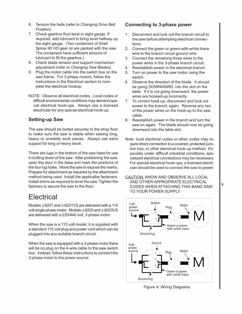
Connecting to 3-phase power
1. Disconnect and lock out the branch circuit tothe saw before attempting electrical connec-tions.
2. Connect the green or green-with-white-tracewire to the branch circuit ground wire.
3. Connect the remaining three wires to thepower wires in the 3-phase branch circuit.
4. Reestablish power in the electrical branch.5. Turn on power to the saw motor using the
switch.6. Observe the direction of the blade. It should
be going DOWNWARD, into the slot on thetable. If it is not going downward, the powerwires are hooked-up incorrectly.
7. To correct hook-up, disconnect and lock outpower to the branch, again. Reverse any twoof the power wires on the hook-up to the sawcable.
8. Reestablish power in the branch and turn thesaw on again. The blade should now be goingdownward into the table slot.
Note: local electrical codes or other codes may re-quire direct connection to a covered, protected junc-tion box, or other electrical hook-up method. Es-pecially under difficult industrial conditions, spe-cialized electrical connections may be necessary.For special electrical hook-ups, a licensed electri-cian should be used to connect the saw to power.
CAUTION: KNOW AND OBSERVE ALL LOCALAND OTHER APPROPRIATE ELECTRICALCODES WHEN ATTACHING THIS BAND SAWTO YOUR POWER SUPPLY.
Figure 4: Wiring Diagrams
Green or greenwith white trace
1-ph.powersource
3-ph.powersource
Motor
Motor
Ground lug
Ground lug
Plug
Plug
Green or greenwith white trace
Switch
Switch

10
GROUNDING INSTRUCTIONS
1. All grounded, cord-connected tools:In the event of a malfunction or breakdown, groundingprovides a path of least resistance for electric currentto reduce the risk of electric shock. This tool isequipped with an electric cord having an equipment-grounding conductor and a grounding plug. The plugmust be plugged into a matching outlet that is prop-erly installed and grounded in accordance with all lo-cal codes and ordinances.
Do not modify the plug provided - if it will not fit theoutlet; have the proper outlet installed by a qualifiedelectrician.
Improper connection of the equipment-grounding con-ductor can result in a risk of electric shock. The con-ductor with insulation having an outer surface that isgreen with or without yellow stripes is the equipment-grounding conductor. If repair or replacement of theelectric cord or plug is necessary, do not connect theequipment-grounding conductor to a live terminal.
Check with a qualified electrician or service person-nel if the grounding instructions are not completelyunderstood, or if in doubt as to whether the tool isproperly grounded.
Use only 3-wire extension cords that have 3-pronggrounding plugs and 3-pole receptacles that acceptthe tool’s plug.
Repair or replace damaged or worn cord immediately.
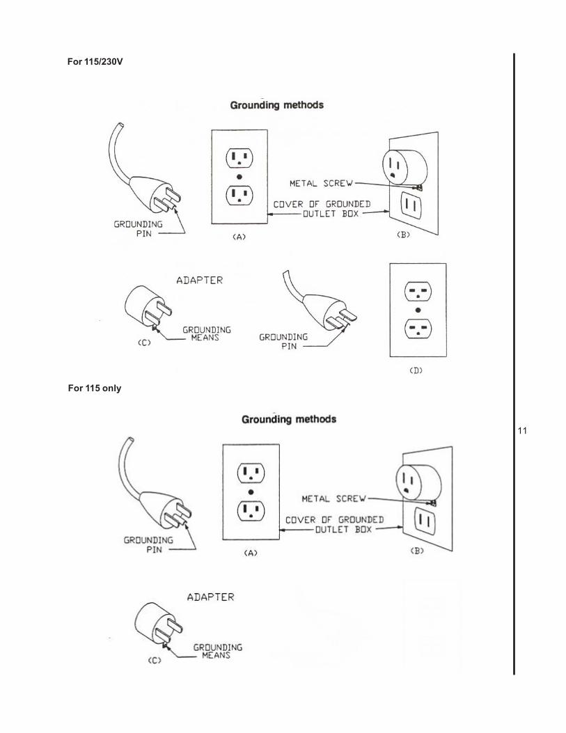
2. Grounded, cord-connected tools intended foruse on a supply circuit having a nominal ratingless than 150 volts:This tool is intended for use on a circuit that has anoutlet that looks like the one illustrated in Sketch A.The tool has a grounding plug that looks like the plugillustrated in Sketch A. A temporary adapter, whichlooks like the adapter illustrated in Sketches B andC, may be used to connect this plug to a 2-pole re-ceptacle as shown in Sketch B if a properly groundedoutlet is not available. The temporary adapter shouldbe used only until a properly grounded outlet can beinstalled by a qualified electrician.(This adapter isnot permitted in Canada) The green-colored rigidear, lug, and the like, extending from the adapter mustbe connected to a permanent ground such as a prop-erly grounded outlet box.
3. Grounded, cord-connected tools intended foruse on a supply circuit having a nominal ratingbetween 150 – 250 volts, inclusive:This tool is intended for use on a circuit that has anoutlet that looks like the one illustrated in Sketch A.The tool has a grounding plug that looks like the plugillustrated in Sketch A. Make sure the tool is con-nected to an outlet having the same configuration asthe plug. No adapter is available or should be usedwith this tool. If the tool must be reconnected for useon a different type of electric circuit, the reconnectionshould be made by qualified service personnel; andafter reconnection, the tool should comply with alllocal codes and ordinances.
4. Permanently connected tools:This tool should be connected to a grounded metalpermanent wiring system; or to a system having anequipment-grounding conductor.
11
For 115/230V
For 115 only

12
Installing Optional Frame Riser
NOTE: Refer to the illustrations in the ReplacementParts section for location of the parts used onthe frame riser.
1. Remove the saw blade (refer to Changing SawBlades).
2. Remove the two screws at the top and bottomof the blade guide that holds the blade guide onthe frame.
WARNING: The saw must be turned off andpower disconnected any time the rubberprotectors are being changed.
3. Unplug the electrical cord or open the circuitbreaker in the branch circuit.
4. Support the upper frame and wheel assemblywith a strap attached to an overhead crane.Use additional straps to be sure the frameassembly will be held in a stable position whenit is lifted off the lower frame assembly.
5. Remove the nut on the bolt that clamps theupper frame to the lower frame and remove thebolt, two washers and nut.
6. Lift the upper frame high enough off of thelower frame to clear the riser casting.
7. Be certain the mating surfaces of the lowerframe, riser, and upper frame are all clean andfree from dirt and debris.
8. Position the riser casting over the lower frame.Make sure the locating dowels are inserted inthe mating holes in the riser casting.
9. Lower the upper frame onto the riser casting.Make sure the locating dowels fit into theirmating holes.
10. Put the new (longer) attaching bolt and topwasher through the upper frame and riser, intothe lower frame.
11. Put a washer and nut on the bolt and tightensecurely.
12. Attach the bracket hooks to the top and bottomof the blade guard using self-tapping screws.
13. Attach the blade guide using the screws thatheld the original (shorter) guard.
14. Remove the old (shorter) blade guide postassembly from the upper frame.
15. The guide support assembly with the carbideguides and blade support bearings should betransferred to the new, longer support rod.Several other new parts are included for thiscomponent. (Refer to the parts illustrations formore detail.)
16. Install a new 105-inch blade (refer to Changinga Blade). Make sure blade tension and tracking
are checked and adjusted as required.18. Install the extension plug cable between the
motor plug and switch plug.19. Plug the electrical cord into the power
source or close the circuit breaker on thebranch circuit. Operate the band saw toverify blade tracking.
Installing Optional Rip Fence
The rip fence slides on two rails attached at thefront and rear of the work table. Install the fencemechanism as follows:
NOTE: Refer to the illustrations in the Replace-ment Parts section for location of the partsused on the rip fence.
1. Slide the rails into the fence.2. Ease the fence and rails into position on the
table.3. Using the four spacers and four attachment
bolts, attach the rails securely to the sawtable.
4. The fence can now be adjusted and usedaccording the instructions in Adjustment andUse of Optional Rip Fence.

13
Operating Controls
START/STOP Switch
The START/STOP switch (refer to Figure 5) isused to turn on the band saw drive motor. TheSTART switch has a molded guard which preventinadvertent pressing of the START pushbutton.
The STOP pushbutton is not guarded to allow useas an E-stop in an emergency.
Variable Speed ControlThe variable speed control (refer to Figure 9) isused to change the speed of the saw blade. Referto Adjusting Blade Speed for additional informa-tion on the use of the variable speed control.
Operating InstructionsSaw blades
The JET14-inch saws accept blades from 1/8-inchwide to 3/4-inch wide. The narrower widths areused for cutting shapes or circles; the wider widthsare used for straight cuts.
For straight cuts, use the widest available sawblade. A wide blade provides cutting stability, andallows for more accurate and straighter cuts.Blade speed effects the efficiency of the cut andthe service life of the blade. Good shop practicerequires that work-hardening materials, such asstainless steel, require the cut be completed in asingle pass. Otherwise, the effect of stopping thecut can result in hardening of the cut interface.
Other materials such as wood require higher bladespeeds to prevent fiber tearing. The chart in
Figure 5. START/STOP Controls
START/STOP Switch
Guarded STARTSwitch
E-Stop
Figure 6 provides suggested blade speeds forvarioustypes of materials. The recommended speedsshould be decreased 30 to 50% when usingcarbon steel blades. (The chart provides speedsthat are based on cutting a 4-inch thick work pieceusing a bi-metal blade without cutting fluid.)
The following conditions should also be consid-ered:1. Increase speed 15% for materials 1/4-inch
thick, 12% for 3/4-inch thick, 10% for 1 1/4-inch thick, and 5% for 2 1/2-inch thick.
2. Decrease speed 12% when cutting 8-inch thickmaterial.
To avoid tooth breakage, select a blade-tooth pitchthat will have two or more teeth in contact with theworkpiece at all times.
Different blade materials and tooth geometry (pitchand set) permit sawing a wide range of commonand exotic materials. Contact your industrialdistributor for recommendations on specializedblades. Using the corrrect blade can save youtime, trouble, and the possibility of dulling andpemature discarding of the blade you normallymight use. NOTE: Always use a sharp blade.SHARP BLADES ARE CHEAP INSURANCEAGAINST POOR CUTTING EFFICIENCY ANDACCELERATED MACHINE WEAR.
Material being cut165160-16511590-100105-13590-11580-140105-11540-8040-7080-10055-9055904040-4525-4030003000300080-1603000300030003000
Structural steel shapesLow carbon steelMedium carbon steelHigh carbon steelCr-moly steelNi-Cr-moly steelChromium steelCr-vanadium steelTool steelStainless steelFree machining steelCast ironCopper alloy (CU-Zm)BronzeAl-bronzeMonelTitanium alloyAluminum (soft)Aluminum (T-6+)CarbonSlatePTFE sheet, rod, roundsHard rubberPlywoodOther woods
Speed (SF/M) range
Figure 6. Blade Speed to Material Chart
Operating Instructions
14
Adjustments
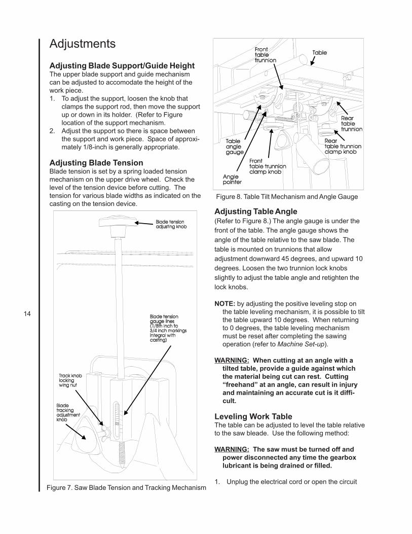
Adjusting Blade Support/Guide HeightThe upper blade support and guide mechanismcan be adjusted to accomodate the height of thework piece.1. To adjust the support, loosen the knob that
clamps the support rod, then move the supportup or down in its holder. (Refer to Figurelocation of the support mechanism.
2. Adjust the support so there is space betweenthe support and work piece. Space of approxi-mately 1/8-inch is generally appropriate.
Adjusting Blade TensionBlade tension is set by a spring loaded tensionmechanism on the upper drive wheel. Check thelevel of the tension device before cutting. Thetension for various blade widths as indicated on thecasting on the tension device.
Figure 8. Table Tilt Mechanism and Angle Gauge
Adjusting Table Angle(Refer to Figure 8.) The angle gauge is under thefront of the table. The angle gauge shows theangle of the table relative to the saw blade. Thetable is mounted on trunnions that allowadjustment downward 45 degrees, and upward 10degrees. Loosen the two trunnion lock knobsslightly to adjust the table angle and retighten thelock knobs.
NOTE: by adjusting the positive leveling stop onthe table leveling mechanism, it is possible to tiltthe table upward 10 degrees. When returningto 0 degrees, the table leveling mechanismmust be reset after completing the sawingoperation (refer to Machine Set-up).
WARNING: When cutting at an angle with atilted table, provide a guide against whichthe material being cut can rest. Cutting“freehand” at an angle, can result in injuryand maintaining an accurate cut is it diffi-cult.
Leveling Work TableThe table can be adjusted to level the table relativeto the saw bleade. Use the following method:
WARNING: The saw must be turned off andpower disconnected any time the gearboxlubricant is being drained or filled.
1. Unplug the electrical cord or open the circuitFigure 7. Saw Blade Tension and Tracking Mechanism
15
breaker in the branch circuit.2. Move the upper blade guide assembly to the
very top of its travel.3. Make sure the blade is straight, and fully
tensioned. (A damaged or worn blade mayprovide a poor reference surface for squaringthe table.)
4. Loosen the table lock knobs and hold thetable firmly against its positive leveling stop.
6. Using a machinist’s square, check to makesure the table is 90 degrees to the blade.USING LEATHER PROTECTIVE GLOVES,turn the upper drive wheel to check thesquareness at a minimum of three points onthe blade
7. If the table is not level, unlock the lock nut onthe table leveling bolt.
8. Turn the leveling bolt as required to make thetable square to the blade.
9. Lock the leveling bolt lock nut and recheck thetable level. When the table is level...
10. Lock the table lock knobs securely andrecheck for level. Adjust as necessary untilthe table is level while everything is tightenedto working tightness.
11. With everything locked down, look at thepointer for the angle gauge. It should beexactly on the zero mark of the gauge (Figure12). If not, loosen the pointer screw, adjust thepointer until it is on zero, then tighten thepointer screw while holding the pointer se-curely in position on zero.
Adjusting Miter Gauge Slot Parallelism
The miter slot should be parallel to the side of theblade. If the saw is not cutting straight when usingthe miter gauge, the miter slot may not be parallel.1. Put a straight edge against the blade. Make
sure to position the blade so tooth offset doesnot affect the straight edge.
VariableSpeedControl
Front View Top View
SpeedIndicator
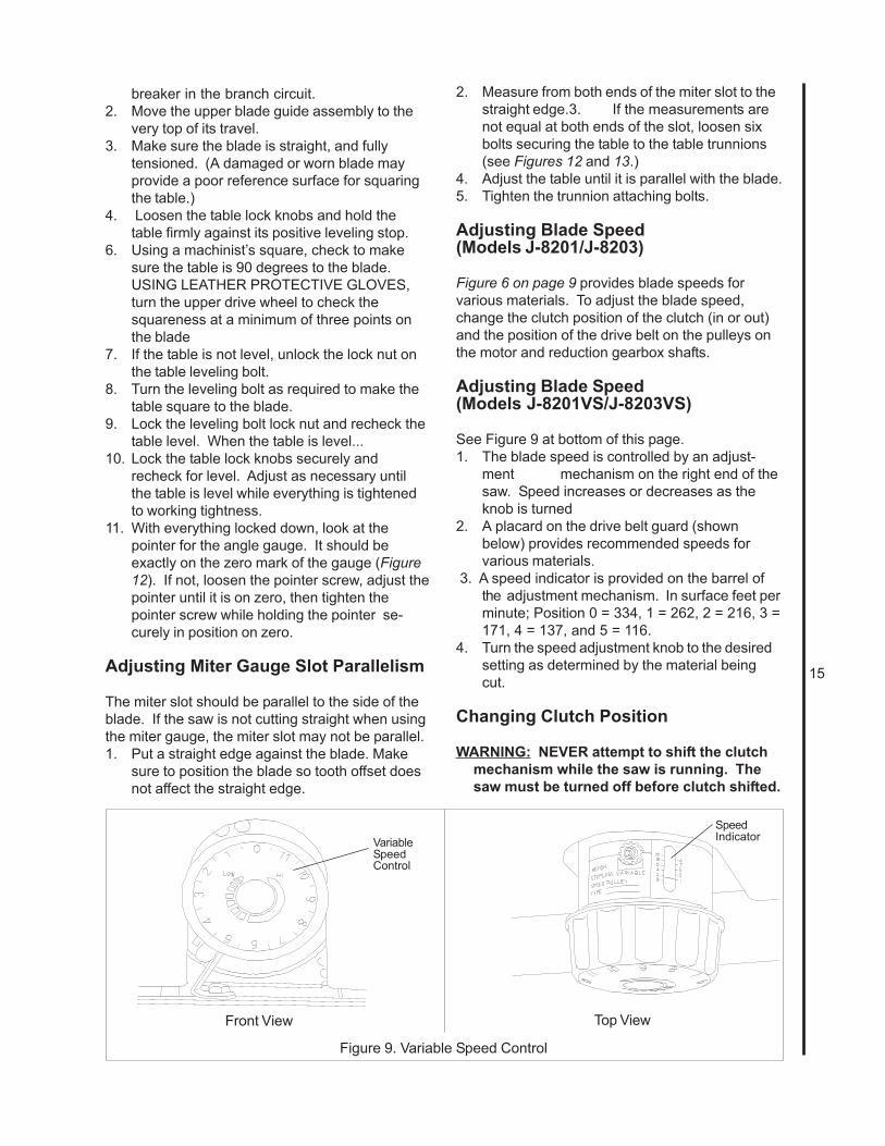
Figure 9. Variable Speed Control
2. Measure from both ends of the miter slot to thestraight edge.3. If the measurements arenot equal at both ends of the slot, loosen sixbolts securing the table to the table trunnions(see Figures 12 and 13.)
4. Adjust the table until it is parallel with the blade.5. Tighten the trunnion attaching bolts.
Adjusting Blade Speed(Models J-8201/J-8203)
Figure 6 on page 9 provides blade speeds forvarious materials. To adjust the blade speed,change the clutch position of the clutch (in or out)and the position of the drive belt on the pulleys onthe motor and reduction gearbox shafts.
Adjusting Blade Speed(Models J-8201VS/J-8203VS)
See Figure 9 at bottom of this page.1. The blade speed is controlled by an adjust-
ment mechanism on the right end of thesaw. Speed increases or decreases as theknob is turned
2. A placard on the drive belt guard (shownbelow) provides recommended speeds forvarious materials.
3. A speed indicator is provided on the barrel ofthe adjustment mechanism. In surface feet perminute; Position 0 = 334, 1 = 262, 2 = 216, 3 =171, 4 = 137, and 5 = 116.
4. Turn the speed adjustment knob to the desiredsetting as determined by the material beingcut.
Changing Clutch Position
WARNING: NEVER attempt to shift the clutchmechanism while the saw is running. Thesaw must be turned off before clutch shifted.
16
1. Turn the main switch to off.2. Pull the door open on the pulley case.3. Turn the clutch handle clockwise and push in,
to engage the high speed pulley drive. Or, turnthe clutch handle clockwise, and pull out, toengage the reduction gearbox drive.
NOTE: When pushing or pulling the clutch knob,the dogs on the clutch mechanism are beingengaged. Take the time make sure the clutchhandle is all the way in, or all the way out, so theclutch dogs are in full engagement when the sawis started.
4. Close the pulley case door.5. Plug the electrical cord into the power source or
close the circuit breaker on the branch circuit.
Changing Drive Belt Position
WARNING: The saw must be turned off andpower disconnected before changing drivebelt positions.
Refer to Figure 9, below.1. Unplug the electrical cord or open the circuit
breaker in the branch circuit.2. Open the door on the machine base and the
door on the pulley case.3. Push up on the motor to pivot the motor
upward and slacken the drive belt.4. Move the drive belt to the desired pulley
position.NOTE: Never force the belts to change pulley
location without pivoting the motor to loosen themotor belt. Failure to do so can cause damageto the drive mechanism, and accelerate beltwear and possibly result in belt failure.
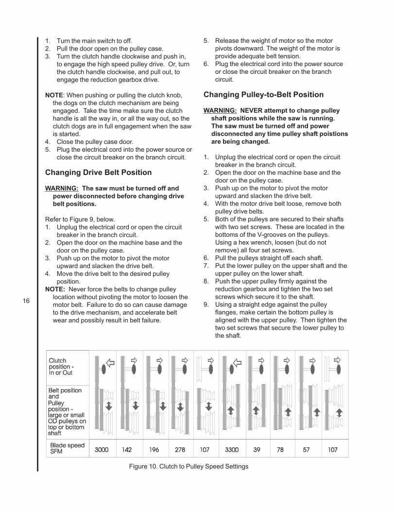
Figure 10. Clutch to Pulley Speed Settings
5. Release the weight of motor so the motorpivots downward. The weight of the motor isprovide adequate belt tension.
6. Plug the electrical cord into the power sourceor close the circuit breaker on the branchcircuit.
Changing Pulley-to-Belt Position
WARNING: NEVER attempt to change pulleyshaft positions while the saw is running.The saw must be turned off and powerdisconnected any time pulley shaft poistionsare being changed.
1. Unplug the electrical cord or open the circuitbreaker in the branch circuit.
2. Open the door on the machine base and thedoor on the pulley case.
3. Push up on the motor to pivot the motorupward and slacken the drive belt.
4. With the motor drive belt loose, remove bothpulley drive belts.
5. Both of the pulleys are secured to their shaftswith two set screws. These are located in thebottoms of the V-grooves on the pulleys.Using a hex wrench, loosen (but do notremove) all four set screws.
6. Pull the pulleys straight off each shaft.7. Put the lower pulley on the upper shaft and the
upper pulley on the lower shaft.8. Push the upper pulley firmly against the
reduction gearbox and tighten the two setscrews which secure it to the shaft.
9. Using a straight edge against the pulleyflanges, make certain the bottom pulley isaligned with the upper pulley. Then tighten thetwo set screws that secure the lower pulley tothe shaft.
17
10. Install the belts as required (refer to Figure 10).11. Release the weight of motor so the motor
pivots downward. The weight of the motor willprovide adequate belt tension.
12. The weight of the motor should providesufficient tension so the the middle of the smalldrive belt is displaced approximately thethickness of the belt. (The high speed belt isadjusted at the same time as the smaller belt.)
13. Set the drive clutch to the desired position (INor OUT).
14. Close the access doors.15. Plug the electrical cord into the power source
or close the circuit breaker on the branchcircuit.
Using Miter System
A miter gauge is provided with the band saw. Themiter gauge slips into a slot in the face of the worktable. The miter gauge can be adjusted from 0 to45 degrees.
Adjust the miter gauge as follows:1. Loosen the clamping screw on the miter
gauge.2. Adjust to desired angle.3. Tighten the clamping screw.
Using Rip Fence
1. Unlock the fence by loosening the lock knob(ref. 7) and handle (ref. 10.)
2. Slide the fence on its guides until it is therequired distance from the blade.
3. Tighten the lock knob and handle, slightly.4. Using a machinist’s square, measure the
distance between the edge of the miter slotand both the front and rear of the rip fence.Adjust so both distances are equal.
5. Check the fence-to-blade gap, again. Read-just the fence, if necessary, until the blade gapis correct and the fence is parallel with themiter slot.
6. Tighten the fence firmly using the lock knoband handle.
Using the Dust Control Chute
On the lower side of the table, below the cuttingposition of the blade, is a plastic tube which can beattached to a shop vacuum, or to a shop dustcontrol system. The dust control chute can be seenin several of the figures used to illustrate theoperation of the saw.
MaintenanceThis section contains periodic maintenancerecommendations and maintenance procedures.
Changing Saw Blade
WARNING: The saw must be turned off andpower disconnected any time saw bladesare being changed.
1. Unplug the electrical cord or open the circuitbreaker in the branch circuit.
2. Pull open both upper and lower drive wheelguards (refer to Figure 1).
3. Release blade tension completely by turningthe tension handle fully counterclockwise.
4. Remove table leveling pin. The pin has a tightpush fit in its slot; it is not threaded. (Refer toFigure 13.
5. Use a screwdriver to pop out the table insert.6. Loosen the set screws that lock the guide
blocks. Move the guide blocks outward. Thenturn the micro-adjusting knob to move theblade support bearing to the very rear of itstravel.
7. Using a hex wrench, loosen the set screw thatlocks the lower blade guide and supportassembly. Move the assembly to the very rearof its travel by using the micro-adjusting knobon the back side of the assembly (refer toFigure 11).
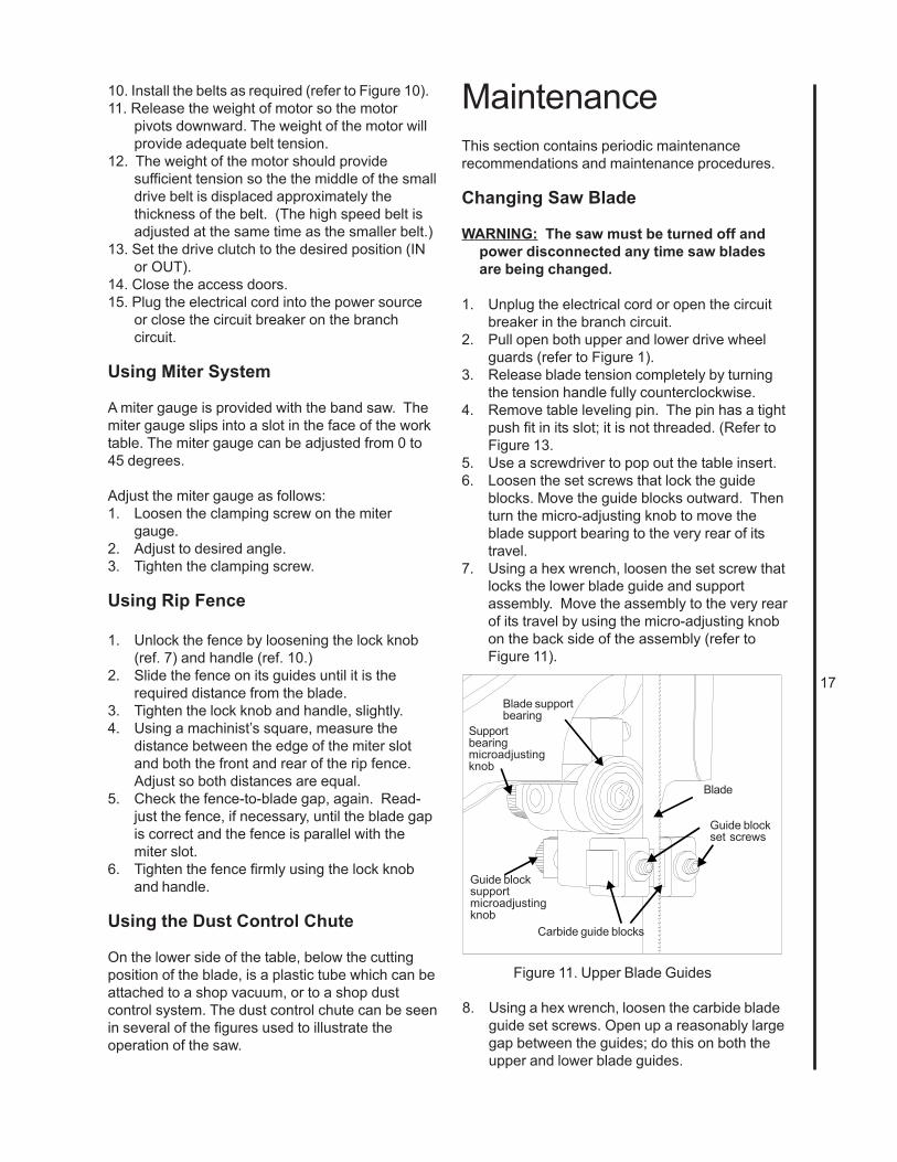
Figure 11. Upper Blade Guides
Guide blocksupportmicroadjustingknob
Supportbearingmicroadjustingknob
Blade supportbearing
Blade
Carbide guide blocks
Guide blockset screws
8. Using a hex wrench, loosen the carbide bladeguide set screws. Open up a reasonably largegap between the guides; do this on both theupper and lower blade guides.
18
9. USING LEATHER GLOVES AND ANSI Z87.1EYEWEAR TO PROTECT YOURSELF FROMTHE CUTTING BLADE, carefully remove theblade from the drive wheels. Remove theblade out of the saw table through the table.
10. Hang the removed blade in a safe place.
NOTE: Clean out the interior of the saw with ashop vacuum. Examine the bearings and otherexposed mechanisms of the saw.
11. Using protective gloves, carefully ease thereplacement blade into the table slot and overthe upper and lower drive wheels.
NOTE: It is possible to install the blade upsidedown. Make sure the teeth on the blade arepointing downward.
NOTE: The blade should be “free standing” at thecutting throat; the upper and lower blade guidesshould not touch the blade at any point. Also,make sure the blade is in the slot in the bladeguard on the left side of the machine frame.Refer to Figure 1 to identify the blade guard.
12. Apply tension to the blade using the tensionknob. The tension levels for various bladewidths are shown on the markings on thetension device. Refer to Figure 3 for a view ofthe tension system.
13. Slowly turn the upper drive wheel by hand,while OBSERVING THE BLADE TRACKING.The blade should track, more or less, in thecenter of the drive wheel. If the blade does nottrack true, adjust the tracking to keep the bladecentered.
14. Unlock the tilt adjustment knob by looseningits locking wing nut. Both the adjustment knoband wing nut are identified in Figure 7.
15. Turn the tilt adjustment knob (usually a VERYLITTLE at a time) to adjust the tilt of the upperdrive wheel. Do this while turning the upperwheel by hand, and adjusting until the bladestays centered on the wheel.
16. Tighten the tilt mechanism locking wing nut.17. Using the micro-adjusting knob, move the
lower blade support assembly (Refer to Figure12) forward until the support bearing justcontacts the back edge of the saw blade.
18. Adjust the lower carbide blade guides until theyjust contact the sides of the blade. Make surethe guides DO NOT CONTACT THE TOOTHPORTION OF THE BLADE. The guidesshould touch only the flat part of the blade.After correctly positioning the carbide guideblocks, tighten the set screws securely.
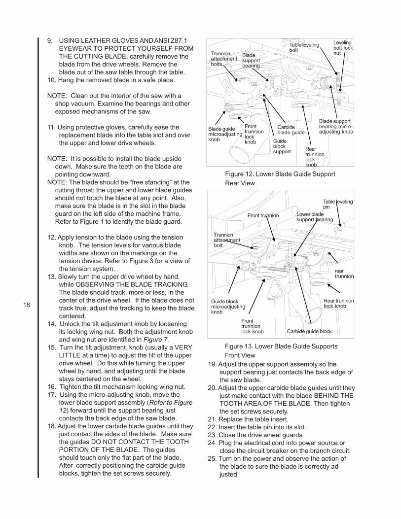
Blade supportbearing micro-adjusting knob
Levelingbolt locknut
Table levelingboltTrunnion
attachmentbolts
Blade guidemicroadjustingknob
Fronttrunnionlockknob Guide
blocksupport
Carbideblade guide
Bladesupportbearing
Reartrunnionlockknob
Figure 12. Lower Blade Guide SupportRear View
Fronttrunnionlock knob
Guide blockmicroadjustingknob
Trunnionattachmentbolt
Front trunnion Lower bladesupport bearing
Table levelingpin
Rear trunnionlock knob
reartrunnion
Carbide guide block
Figure 13. Lower Blade Guide SupportsFront View
19. Adjust the upper support assembly so thesupport bearing just contacts the back edge ofthe saw blade.
20. Adjust the upper carbide blade guides until theyjust make contact with the blade BEHIND THETOOTH AREA OF THE BLADE. Then tightenthe set screws securely.
21. Replace the table insert.22. Insert the table pin into its slot.23. Close the drive wheel guards.24. Plug the electrical cord into power source or
close the circuit breaker on the branch circuit.25. Turn on the power and observe the action of
the blade to sure the blade is correctly ad-justed.
19
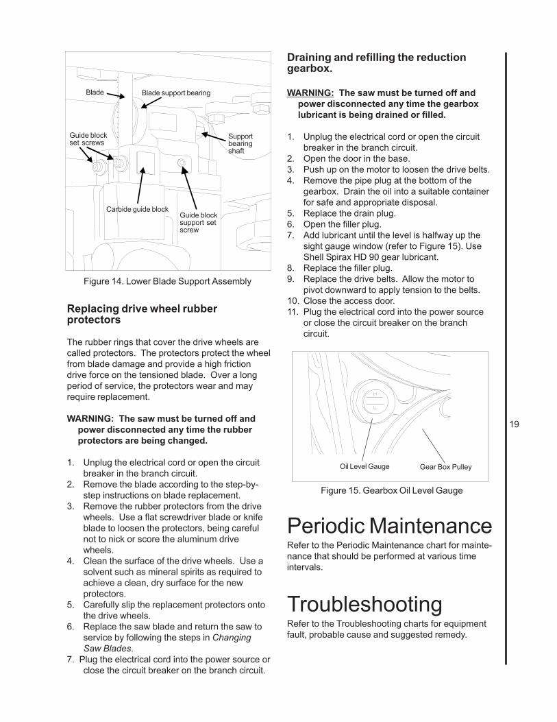
Carbide guide block
Blade Blade support bearing
Guide blockset screws
Supportbearingshaft
Guide blocksupport setscrew
Figure 14. Lower Blade Support Assembly
Replacing drive wheel rubberprotectors
The rubber rings that cover the drive wheels arecalled protectors. The protectors protect the wheelfrom blade damage and provide a high frictiondrive force on the tensioned blade. Over a longperiod of service, the protectors wear and mayrequire replacement.
WARNING: The saw must be turned off andpower disconnected any time the rubberprotectors are being changed.
1. Unplug the electrical cord or open the circuitbreaker in the branch circuit.
2. Remove the blade according to the step-by-step instructions on blade replacement.
3. Remove the rubber protectors from the drivewheels. Use a flat screwdriver blade or knifeblade to loosen the protectors, being carefulnot to nick or score the aluminum drivewheels.
4. Clean the surface of the drive wheels. Use asolvent such as mineral spirits as required toachieve a clean, dry surface for the newprotectors.
5. Carefully slip the replacement protectors ontothe drive wheels.
6. Replace the saw blade and return the saw toservice by following the steps in ChangingSaw Blades.
7. Plug the electrical cord into the power source orclose the circuit breaker on the branch circuit.
Draining and refilling the reductiongearbox.
WARNING: The saw must be turned off andpower disconnected any time the gearboxlubricant is being drained or filled.
1. Unplug the electrical cord or open the circuitbreaker in the branch circuit.
2. Open the door in the base.3. Push up on the motor to loosen the drive belts.4. Remove the pipe plug at the bottom of the
gearbox. Drain the oil into a suitable containerfor safe and appropriate disposal.
5. Replace the drain plug.6. Open the filler plug.7. Add lubricant until the level is halfway up the
sight gauge window (refer to Figure 15). UseShell Spirax HD 90 gear lubricant.
8. Replace the filler plug.9. Replace the drive belts. Allow the motor to
pivot downward to apply tension to the belts.10. Close the access door.11. Plug the electrical cord into the power source
or close the circuit breaker on the branchcircuit.
Oil Level Gauge Gear Box Pulley
Figure 15. Gearbox Oil Level Gauge
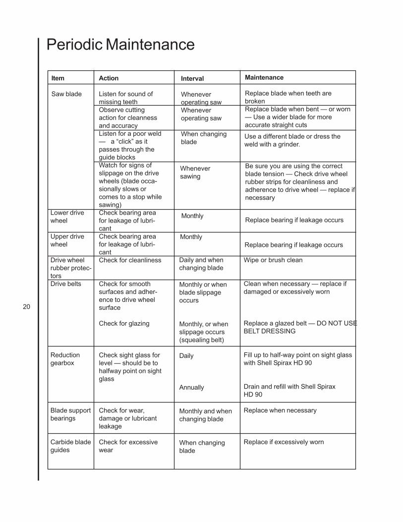
Periodic MaintenanceRefer to the Periodic Maintenance chart for mainte-nance that should be performed at various timeintervals.
TroubleshootingRefer to the Troubleshooting charts for equipmentfault, probable cause and suggested remedy.
20
Periodic Maintenance
Maintenance
Replace blade when teeth arebrokenReplace blade when bent — or worn— Use a wider blade for moreaccurate straight cuts
Interval
Wheneveroperating sawWheneveroperating saw
When changingblade
Action
Listen for sound ofmissing teethObserve cuttingaction for cleannessand accuracyListen for a poor weld— a “click” as itpasses through theguide blocksWatch for signs ofslippage on the drivewheels (blade occa-sionally slows orcomes to a stop whilesawing)Check bearing areafor leakage of lubri-cantCheck bearing areafor leakage of lubri-cantCheck for cleanliness
Check for smoothsurfaces and adher-ence to drive wheelsurface
Check for glazing
Check sight glass forlevel — should be tohalfway point on sightglass
Check for wear,damage or lubricantleakage
Check for excessivewear
Item
Saw blade
Wheneversawing
Use a different blade or dress theweld with a grinder.
Be sure you are using the correctblade tension — Check drive wheelrubber strips for cleanliness andadherence to drive wheel — replace ifnecessary
Lower drivewheel
Upper drivewheel
Drive wheelrubber protec-torsDrive belts
Reductiongearbox
Blade supportbearings
Carbide bladeguides
Monthly
Monthly
Daily and whenchanging blade
Monthly or whenblade slippageoccurs
Monthly, or whenslippage occurs(squealing belt)
Daily
Annually
Monthly and whenchanging blade
When changingblade
Replace bearing if leakage occurs
Replace bearing if leakage occurs
Wipe or brush clean
Clean when necessary — replace ifdamaged or excessively worn
Replace a glazed belt — DO NOT USEBELT DRESSING
Fill up to half-way point on sight glasswith Shell Spirax HD 90
Drain and refill with Shell SpiraxHD 90
Replace when necessary
Replace if excessively worn
21
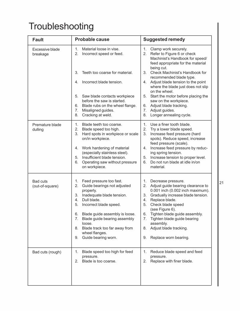
TroubleshootingFault
Excessive bladebreakage
Premature bladedulling
Bad cuts(out-of-square)
Bad cuts (rough)
Probable cause
1. Material loose in vise.2. Incorrect speed or feed.
3. Teeth too coarse for material.
4. Incorrect blade tension.
5. Saw blade contacts workpiecebefore the saw is started.
6. Blade rubs on the wheel flange.7. Misaligned guides.8. Cracking at weld.
1. Blade teeth too coarse.2. Blade speed too high.3. Hard spots in workpiece or scale
on/in workpiece.
4. Work hardening of material(especially stainless steel).
5. Insufficient blade tension.6. Operating saw without pressure
on workpiece.
1. Feed pressure too fast.2. Guide bearings not adjusted
properly.3. Inadequate blade tension.4. Dull blade.5. Incorrect blade speed.
6. Blade guide assembly is loose.7. Blade guide bearing assembly
loose.8. Blade track too far away from
wheel flanges.9. Guide bearing worn.
1. Blade speed too high for feedpressure.
2. Blade is too coarse.
Suggested remedy
1. Clamp work securely.2. Refer to Figure 6 or check
Machinist’s Handbook for speed/feed appropriate for the materialbeing cut.
3. Check Machinist’s Handbook forrecommended blade type.
4. Adjust blade tension to the pointwhere the blade just does not slipon the wheel.
5. Start the motor before placing thesaw on the workpiece.
6. Adjust blade tracking.7. Adjust guides.8. Longer annealing cycle.
1. Use a finer tooth blade.2. Try a lower blade speed.3. Increase feed pressure (hard
spots). Reduce speed, increasefeed pressure (scale).
4. Increase feed pressure by reduc-ing spring tension.
5. Increase tension to proper level.6. Do not run blade at idle in/on
material.
1. Decrease pressure.2. Adjust guide bearing clearance to
0.001 inch (0.002 inch maximum).3. Gradually increase blade tension.4. Replace blade.5. Check blade speed
(see Figure 6).6. Tighten blade guide assembly.7. Tighten blade guide bearing
assembly.8. Adjust blade tracking.
9. Replace worn bearing.
1. Reduce blade speed and feedpressure.
2. Replace with finer blade.
22
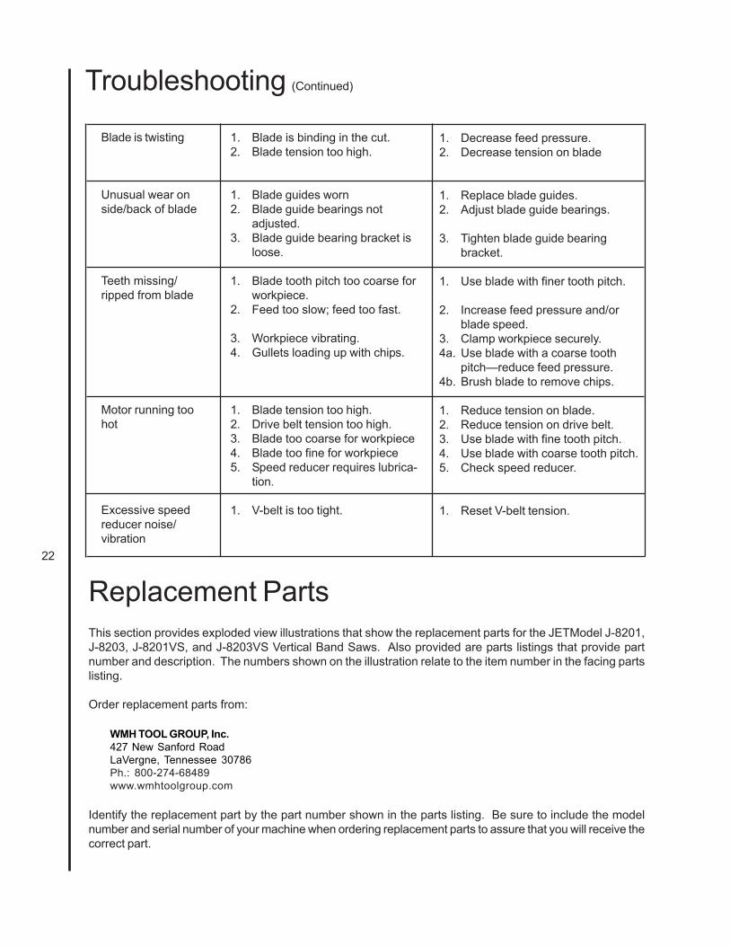
1. Blade is binding in the cut.2. Blade tension too high.
1. Blade guides worn2. Blade guide bearings not
adjusted.3. Blade guide bearing bracket is
loose.
1. Blade tooth pitch too coarse forworkpiece.
2. Feed too slow; feed too fast.
3. Workpiece vibrating.4. Gullets loading up with chips.
1. Blade tension too high.2. Drive belt tension too high.3. Blade too coarse for workpiece4. Blade too fine for workpiece5. Speed reducer requires lubrica-
tion.
1. V-belt is too tight.
Blade is twisting
Unusual wear onside/back of blade
Teeth missing/ripped from blade
Motor running toohot
Excessive speedreducer noise/vibration
1. Decrease feed pressure.2. Decrease tension on blade
1. Replace blade guides.2. Adjust blade guide bearings.
3. Tighten blade guide bearingbracket.
1. Use blade with finer tooth pitch.
2. Increase feed pressure and/orblade speed.
3. Clamp workpiece securely.4a. Use blade with a coarse tooth
pitch—reduce feed pressure.4b. Brush blade to remove chips.
1. Reduce tension on blade.2. Reduce tension on drive belt.3. Use blade with fine tooth pitch.4. Use blade with coarse tooth pitch.5. Check speed reducer.
1. Reset V-belt tension.
Troubleshooting (Continued)
Replacement PartsThis section provides exploded view illustrations that show the replacement parts for the JETModel J-8201,J-8203, J-8201VS, and J-8203VS Vertical Band Saws. Also provided are parts listings that provide partnumber and description. The numbers shown on the illustration relate to the item number in the facing partslisting.
Order replacement parts from:
WMH TOOL GROUP, Inc.427 New Sanford RoadLaVergne, Tennessee 30786Ph.: 800-274-68489www.wmhtoolgroup.com
Identify the replacement part by the part number shown in the parts listing. Be sure to include the modelnumber and serial number of your machine when ordering replacement parts to assure that you will receive thecorrect part.
23
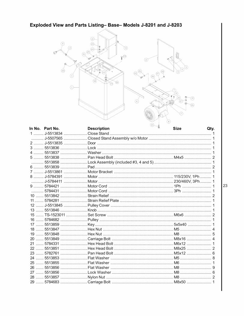
Exploded View and Parts Listing– Base– Models J-8201 and J-8203
In No. Part No. Description Size Qty.1 ......... J-5513834 .....................Close Stand ........................................................................................... 1........... J-5507565 .....................Closed Stand Assembly w/o Motor ........................................................ 12 ......... J-5513835 .....................Door ...................................................................................................... 13 ......... 5513836 ........................Lock ...................................................................................................... 14 ......... 5513837 ........................Washer .................................................................................................. 15 ......... 5513838 ........................Pan Head Bolt ..................................................... M4x5 ........................ 2........... 5513858 ........................Lock Assembly (included #3, 4 and 5) ................................................... 16 ......... 5513839 ........................Pad........................................................................................................ 27 ......... J-5513861 .....................Motor Bracket ....................................................................................... 18 ......... J-5784391 .....................Motor ................................................................... 115/230V, 1Ph .......... 1........... J-5784411 .....................Motor ................................................................... 230/460V, 3Ph.......... 19 ......... 5784421 ........................Motor Cord .......................................................... 1Ph .......................... 1........... 5784431 ........................Motor Cord .......................................................... 3Ph .......................... 110 ....... 5513842 ........................Strain Relief ........................................................................................... 211 ........ 5784281 ........................Strain Relief Plate .................................................................................. 112 ....... J-5513845 .....................Pulley Cover .......................................................................................... 113 ....... 5513846 ........................Knob ...................................................................................................... 115 ....... TS-1523011 ...................Set Screw ...........................................................M6x6 ........................ 216 ....... 5784682 ........................Pulley .................................................................................................... 117 ....... 5513859 ........................Key...................................................................... 5x5x40 ..................... 118 ....... 5513847 ........................Hex Nut ............................................................... M5 ............................ 419 ....... 5513848 ........................Hex Nut ............................................................... M8 ............................ 520 ....... 5513849 ........................Carriage Bolt ....................................................... M8x16 ...................... 421 ....... 5784331 ........................Hex Head Bolt ..................................................... M6x12 ...................... 122 ....... 5513851 ........................Hex Head Bolt ..................................................... M8x25 ...................... 223 ....... 5782761 ........................Pan Head Bolt ..................................................... M5x12 ...................... 624 ....... 5513853 ........................Flat Washer ........................................................ M5 ............................ 825 ....... 5513855 ........................Flat Washer ........................................................ M6 ............................ 126 ....... 5513856 ........................Flat Washer ........................................................ M8 ............................ 927 ....... 5513856 ........................Lock Washer ....................................................... M8 ............................ 628 ....... 5513857 ........................Nylon Nut ............................................................ M8 ............................ 229 ....... 5784683 ........................Carriage Bolt ....................................................... M8x50 ...................... 1
24
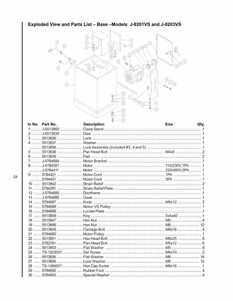
Exploded View and Parts List – Base –Models J-8201VS and J-8203VS
In No. Part No. Description Size Qty.1 ......... J-5513860 .....................Close Stand ........................................................................................... 12 ......... J-5513835 .....................Door ...................................................................................................... 13 ......... 5513836 ........................Lock ...................................................................................................... 14 ......... 5513837 ........................Washer .................................................................................................. 1........... 5513858 ........................Lock Assembly (included #3, 4 and 5) ................................................... 15 ......... 5513838 ........................Pan Head Bolt ..................................................... M4x5 ........................ 26 ......... 5513839 ........................Pad........................................................................................................ 27 ......... J-5784684 .....................Motor Bracket ....................................................................................... 18 ......... J-5784391 .....................Motor ................................................................... 115/230V,1Ph ........... 1........... J-5784411 .....................Motor ................................................................... 230/460V,3Ph ........... 19 ......... 5784421 ........................Motor Cord .......................................................... 1Ph .......................... 1........... 5784431 ........................Motor Cord .......................................................... 3Ph .......................... 110 ....... 5513842 ........................Strain Relief ........................................................................................... 211 ........ 5784281 ........................Strain Relief Plate .................................................................................. 112 ....... J-5784685 .....................Doorframe .............................................................................................. 113 ....... J-5784686 .....................Cover ..................................................................................................... 114 ....... 5784687 ........................Knob .................................................................... M5x12 ...................... 215 ....... 5784688 ........................Motor VS Pulley .................................................................................... 116 ....... 5784689 ........................Locate Plate .......................................................................................... 117 ....... 5513859 ........................Key...................................................................... 5x5x40 ..................... 118 ....... 5513847 ........................Hex Nut ............................................................... M5 ............................ 419 ....... 5513848 ........................Hex Nut ............................................................... M8 .......................... 1220 ....... 5513849 ........................Carriage Bolt ....................................................... M8x16 ...................... 421 ....... 5784690 ........................Motor Pulley .......................................................................................... 122 ....... 5513851 ........................Hex Head Bolt ..................................................... M8x25 ...................... 823 ....... 5782761 ........................Pan Head Bolt ..................................................... M5x12 ...................... 624 ....... 5513853 ........................Flat Washer ........................................................ M5 ............................ 825 ....... TS-1523031...................Set Screw ...........................................................M6x10 ...................... 226 ....... 5513856 ........................Flat Washer ........................................................ M8 .......................... 1627 ....... 5513856 ........................Lock Washer ....................................................... M8 .......................... 1228 ....... TS-1490021...................Hex Cap Screw ................................................... M8x16 ...................... 129 ....... 5784692 ........................Rubber Foot .......................................................................................... 430 ....... 5784693 ........................Special Washer ..................................................................................... 4
25
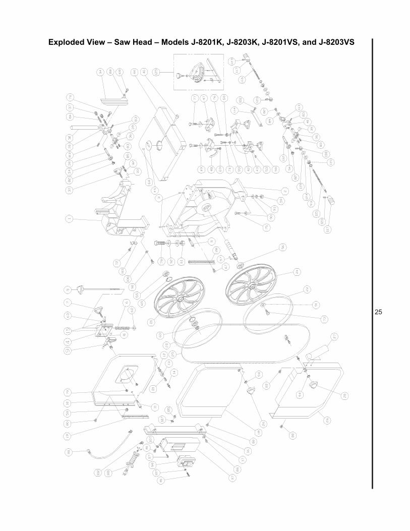
Exploded View – Saw Head – Models J-8201K, J-8203K, J-8201VS, and J-8203VS

26
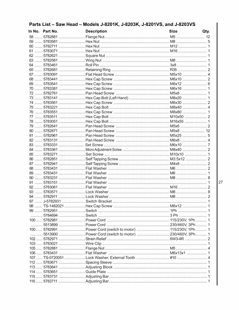
Parts List – Saw Head – Models J-8201K, J-8203K, J-8201VS, and J-8203VS
1 ......... J-5782511 .....................Upper Arm, Frame ................................................................................. 12 ......... J-5783041 .....................Base ...................................................................................................... 13 ......... 5783241 ........................Dowel Pin .............................................................................................. 44 ......... 5782521 ........................Upper Wheel Sliding Bracket ................................................................ 15 ......... 5782591 ........................Blade Tension Adjustment Knob ............................................................ 16 ......... 5782611 ........................Tension Spring ....................................................................................... 17 ......... 5782571 ........................Blade Track Adjustment Knob ....................................... M8x55 ........................... 18 ......... 5782541 ........................Pivot Pin ................................................................................................ 29 ......... 5782531 ........................Upper Wheel Hinge w/ Shaft .................................................................. 110 ....... J-5782631 ..................... Inner Upper Wheel Guard ...................................................................... 111 ........ 5782821 ........................Stud ....................................................................................................... 212 ....... 5782741 ........................Fixed Bolt .............................................................................................. 213 ....... 5782751 ........................Catch ..................................................................................................... 214 ....... 170080 ..........................Stud Latch ............................................................................................. 215 ....... TS-1522021...................Set Screw ...........................................................M5x8 ........................ 216 ....... 5782831 ........................Blade Guard .......................................................................................... 117 ....... 5782841 ........................Retainer ................................................................................................. 218 ....... J-5782891 .....................Outer Upper Wheel Guard ..................................................................... 119 ....... 5782861 ........................Hinge (Upper) ........................................................................................ 120 ....... 5782921 ........................Knob .................................................................... M8 ............................ 221 ....... 5782661 ........................Upper Wheel ......................................................................................... 122 ....... 5782691 ........................Wheel Protector .................................................................................... 224 ....... 5783161 ........................Lower Wheel ......................................................................................... 125 ....... 5782722 ........................Saw Blade for Metal Cutting ................................ 92-1/2 x 14T/in ......... 1........... 5782732 ........................Saw Blade for Wood Cutting ................................. 92-1/2 x 6T/in ............ 126 ....... J-5783111 ......................Lower Wheel Guard ............................................................................... 127 ....... 5783121 ........................Dust Chute ............................................................................................ 128 ....... 5783081 ........................Hinge (Lower) ........................................................................................ 130 ....... 5783351 ........................Guide Post ............................................................................................ 131 ....... 5783281 ........................Knob .................................................................... M10x30 .................... 132 ....... 5783261 ........................Spring .................................................................................................... 133 ....... 5783251 ........................Steel Ball ............................................................. 8mm ......................... 134 ....... 5783421 ........................Upper Wheel Blade Guard ..................................................................... 135 ....... 5783341 ........................Upper Support Bracket Post .................................................................. 136 ....... 5783411 ........................Support Bracket .................................................................................... 237 ....... 5783371 ........................Micro Adjustment Nut ............................................................................ 238 ....... 5783321 ........................Upper Spacing Sleeve ............................................................................ 239 ....... 5783391 ........................Carbide Blade Guide .............................................................................. 440 ....... 5783631 ........................Lower Support Bracket Post .................................................................. 142 ....... 5783591 ........................Bracket Trunnion Support ...................................................................... 143 ....... 5783611 ........................Point ...................................................................................................... 144 ....... J-5783451 .....................Table ...................................................................................................... 145 ....... 5783471 ........................Table Insert ............................................................................................ 146 ....... 5783481 ........................Table Pin ............................................................................................... 147 ....... 5783521 ........................Trunnion ................................................................................................. 248 ....... 5783531 ........................Scale ..................................................................................................... 149 ....... 5783491 ........................Trunnion Clamp Shoe ............................................................................ 250 ....... 5783621 ........................Knob .................................................................... M10 .......................... 253 ....... 5782641 ........................Pan Head Screw ................................................. M5x6 ........................ 154 ....... 5783311 ........................Bearing ................................................................ 6200ZZ ..................... 255 ....... 5782671 ........................Bearing ................................................................ 6202Z ....................... 256 ....... 5783171 ........................Bearing ................................................................ 6204LLU ................... 157 ....... 5783211 ........................Key...................................................................... 5x5x20 ..................... 2
In No. Part No. Description Size Qty.
27
58 ....... 5782881 ........................Flange Nut ........................................................... M5 .......................... 1259 ....... 5783581 ........................Hex Nut ............................................................... M8 ............................ 560 ....... 5782711 ........................Hex Nut ............................................................... M12 .......................... 161 ....... 5783071 ........................Hex Nut ............................................................... M16 .......................... 162 ....... 5782621 ........................Square Nut ............................................................................................ 163 ....... 5782581 ........................Wing Nut ............................................................. M8 ............................ 164 ....... 5783461 ........................Roll Pin ................................................................ 3x8 ........................... 165 ....... 5782681 ........................Retaining Ring ..................................................... R35 .......................... 267 ....... 5783091 ........................Flat Head Screw .................................................. M5x10 ...................... 468 ....... 5783441 ........................Hex Cap Screw ................................................... M6x10 ...................... 269 ....... 5783541 ........................Hex Cap Screw ................................................... M6x12 ...................... 670 ....... 5783381 ........................Hex Cap Screw ................................................... M6x16 ...................... 172 ....... 5782761 ........................Pan Head Screw ................................................. M5x8 ........................ 173 ....... 5783141 ........................Hex Cap Bolt (Left Hand) ..................................... M8x20 ...................... 174 ....... 5783561 ........................Hex Cap Screw ................................................... M6x30 ...................... 275 ....... 5783221 ........................Hex Cap Bolt ....................................................... M8x40 ...................... 476 ....... 5783551 ........................Hex Cap Screw ................................................... M8x80 ...................... 177 ....... 5783511 ........................Hex Cap Bolt ....................................................... M10x50 .................... 278 ....... 5783051 ........................Hex Cap Bolt ....................................................... M16x55 .................... 179 ....... 5782641 ........................Pan Head Screw ................................................. M5x6 ........................ 280 ....... 5782871 ........................Pan Head Screw ................................................. M5x8 ...................... 1281 ....... 5782961 ........................Pan Head Screw ................................................. M5x25 ...................... 582 ....... 5783131 ........................Pan Head Screw ................................................. M6x8 ........................ 483 ....... 5783331 ....................... Set Screw ............................................................M6x10 ...................... 784 ....... 5783361 ........................Micro Adjustment Screw ................................................ M8x40 ...................... 285 ....... 5783271 ........................Set Screw ...........................................................M10x10 .................... 186 ....... 5782851 ........................Self Tapping Screw .............................................. M3.5x12 ................... 287 ....... 5782941 ........................Self Tapping Screw .............................................. M4x8 ........................ 288 ....... 5783431 ........................Flat Washer ........................................................ M6 ............................ 289 ....... 5783431 ........................Flat Washer ........................................................ M6 ............................ 190 ....... 5783231 ........................Flat Washer ........................................................ M8 ............................ 891 ....... 5783151 ........................Flat Washer .......................................................................................... 192 ....... 5783061 ........................Flat Washer ........................................................ M16 .......................... 293 ....... 5783571 ........................Lock Washer ....................................................... M8 ............................ 894 ....... 5782911 ........................Lock Washer ....................................................... M8 ............................ 297 ....... J-5782931 .....................Switch Bracket ...................................................................................... 198 ....... TS-1482021...................Hex Cap Screw ................................................... M6x12 ...................... 199 ....... 5782951 ........................Switch ................................................................. 1Ph .......................... 1........... 5784694 ........................Switch ................................................................. 3 Ph ......................... 1
100...... 5782981 ........................Power Cord ......................................................... 115/230V, 1Ph .......... 1........... 5513899 ........................Power Cord ......................................................... 230/460V, 3Ph.......... 1
100...... 5782991 ........................Power Cord (switch to motor) .............................. 115/230V, 1Ph .......... 1........... 5513900 ........................Power Cord (switch to motor) .............................. 230/460V, 3Ph.......... 1
102...... 5782971 ........................Strain Relief ......................................................... 6W3-4R .................... 2103...... 5783021 ........................Wire Clip ............................................................................................... 1105...... 5782881 ........................Flange Nut ........................................................... M5 ............................ 4106...... 5783431 ........................Flat Washer ........................................................M6x13x1 .................. 1107...... TS-0720051...................Lock Washer, External Tooth .............................. #10 ........................... 4112 ...... 5783671 ........................Spacing Sleeve ...................................................................................... 1113 ...... 5783641 ........................Adjusting Block ..................................................................................... 1114 ...... 5783651 ........................Guide Plate ........................................................................................... 1115 ...... 5783731 ........................Adjusting Bar ......................................................................................... 1116 ...... 5783711 ........................Adjusting Bar ......................................................................................... 1
Parts List – Saw Head – Models J-8201K, J-8203K, J-8201VS, and J-8203VSIn No. Part No. Description Size Qty.

28
Parts List – Saw Head – Models J-8201K, J-8203K, J-8201VS, and J-8203VS
117 ...... 5783721 ........................Handle ................................................................................................... 2118 ...... 5783681 ........................Setting Bushing ..................................................................................... 2119 ...... 5783771 ........................Spacer ................................................................................................... 2121...... 5783751 ........................Flange Nut ........................................................... M8 ............................ 2122...... 5783661 ........................Flat Head Socket Screw ...................................... M6x15 ...................... 2123...... 5783691 ........................Set Screw ...........................................................M5x5 ........................ 4124...... 5783761 ........................Wave Washer ...................................................... 8x13 ......................... 2125...... 5784695 ........................Miter Gauge Assembly .......................................................................... 1
In No. Part No. Description Size Qty.
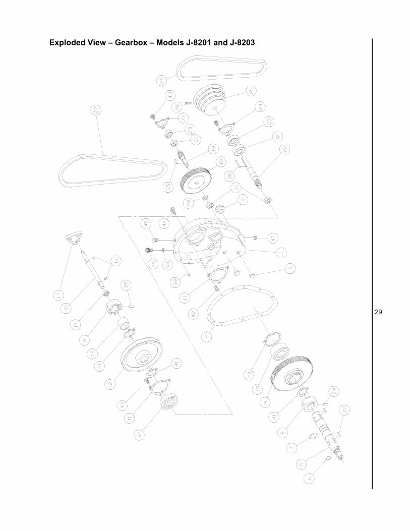
29
Exploded View – Gearbox – Models J-8201 and J-8203
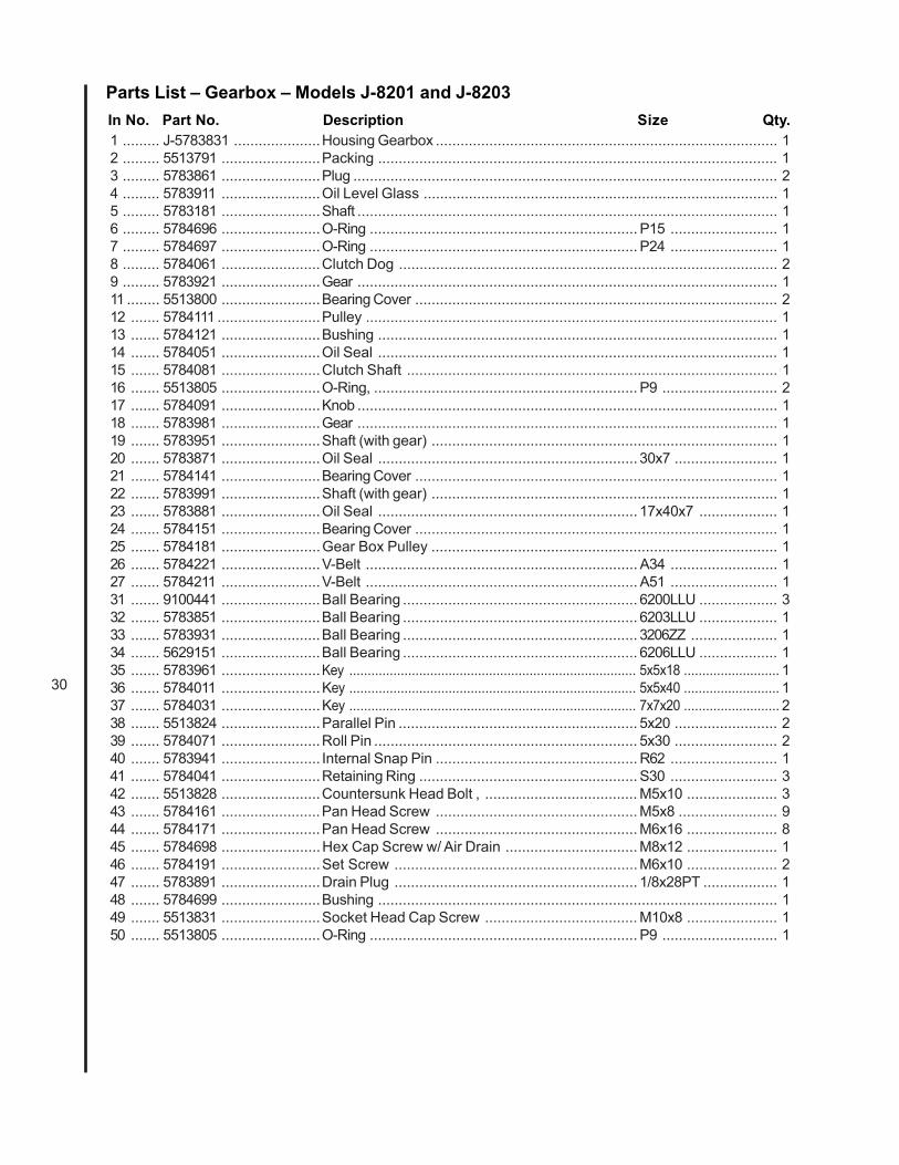
30
Parts List – Gearbox – Models J-8201 and J-8203In No. Part No. Description Size Qty.1 ......... J-5783831 .....................Housing Gearbox ................................................................................... 12 ......... 5513791 ........................Packing ................................................................................................. 13 ......... 5783861 ........................Plug ....................................................................................................... 24 ......... 5783911 ........................Oil Level Glass ...................................................................................... 15 ......... 5783181 ........................Shaft ...................................................................................................... 16 ......... 5784696 ........................O-Ring ................................................................. P15 .......................... 17 ......... 5784697 ........................O-Ring ................................................................. P24 .......................... 18 ......... 5784061 ........................Clutch Dog ............................................................................................ 29 ......... 5783921 ........................Gear ...................................................................................................... 111 ........ 5513800 ........................Bearing Cover ........................................................................................ 212 ....... 5784111 .........................Pulley .................................................................................................... 113 ....... 5784121 ........................Bushing ................................................................................................. 114 ....... 5784051 ........................Oil Seal ................................................................................................. 115 ....... 5784081 ........................Clutch Shaft .......................................................................................... 116 ....... 5513805 ........................O-Ring, ................................................................ P9 ............................ 217 ....... 5784091 ........................Knob ...................................................................................................... 118 ....... 5783981 ........................Gear ...................................................................................................... 119 ....... 5783951 ........................Shaft (with gear) .................................................................................... 120 ....... 5783871 ........................Oil Seal ............................................................... 30x7 ......................... 121 ....... 5784141 ........................Bearing Cover ........................................................................................ 122 ....... 5783991 ........................Shaft (with gear) .................................................................................... 123 ....... 5783881 ........................Oil Seal ............................................................... 17x40x7 ................... 124 ....... 5784151 ........................Bearing Cover ........................................................................................ 125 ....... 5784181 ........................Gear Box Pulley .................................................................................... 126 ....... 5784221 ........................V-Belt .................................................................. A34 .......................... 127 ....... 5784211 ........................V-Belt .................................................................. A51 .......................... 131 ....... 9100441 ........................Ball Bearing ......................................................... 6200LLU ................... 332 ....... 5783851 ........................Ball Bearing ......................................................... 6203LLU ................... 133 ....... 5783931 ........................Ball Bearing ......................................................... 3206ZZ ..................... 134 ....... 5629151 ........................Ball Bearing ......................................................... 6206LLU ................... 135 ....... 5783961 ........................Key .............................................................................. 5x5x18 .......................... 136 ....... 5784011 ........................Key .............................................................................. 5x5x40 .......................... 137 ....... 5784031 ........................Key .............................................................................. 7x7x20 .......................... 238 ....... 5513824 ........................Parallel Pin .......................................................... 5x20 ......................... 239 ....... 5784071 ........................Roll Pin ................................................................ 5x30 ......................... 240 ....... 5783941 ........................ Internal Snap Pin ................................................. R62 .......................... 141 ....... 5784041 ........................Retaining Ring ..................................................... S30 .......................... 342 ....... 5513828 ........................Countersunk Head Bolt , ..................................... M5x10 ...................... 343 ....... 5784161 ........................Pan Head Screw ................................................. M5x8 ........................ 944 ....... 5784171 ........................Pan Head Screw ................................................. M6x16 ...................... 845 ....... 5784698 ........................Hex Cap Screw w/ Air Drain ................................ M8x12 ...................... 146 ....... 5784191 ........................Set Screw ...........................................................M6x10 ...................... 247 ....... 5783891 ........................Drain Plug ........................................................... 1/8x28PT .................. 148 ....... 5784699 ........................Bushing ................................................................................................. 149 ....... 5513831 ........................Socket Head Cap Screw ..................................... M10x8 ...................... 150 ....... 5513805 ........................O-Ring ................................................................. P9 ............................ 1

31
Exploded View – Gearbox – Models J-8201VS and J-8203VS
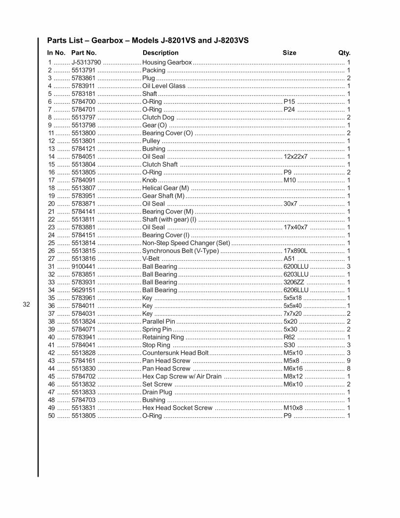
32
Parts List – Gearbox – Models J-8201VS and J-8203VSIn No. Part No. Description Size Qty.1 ......... J-5313790 .....................Housing Gearbox ................................................................................... 12 ......... 5513791 ........................Packing ................................................................................................. 13 ......... 5783861 ........................Plug ....................................................................................................... 24 ......... 5783911 ........................Oil Level Glass ...................................................................................... 15 ......... 5783181 ........................Shaft ...................................................................................................... 16 ......... 5784700 ........................O-Ring ................................................................. P15 .......................... 17 ......... 5784701 ........................O-Ring ................................................................. P24 .......................... 18 ......... 5513797 ........................Clutch Dog ............................................................................................ 29 ......... 5513798 ........................Gear (O) ................................................................................................ 111 ........ 5513800 ........................Bearing Cover (O) .................................................................................. 212 ....... 5513801 ........................Pulley .................................................................................................... 113 ....... 5784121 ........................Bushing ................................................................................................. 114 ....... 5784051 ........................Oil Seal ............................................................... 12x22x7 ................... 115 ....... 5513804 ........................Clutch Shaft .......................................................................................... 116 ....... 5513805 ........................O-Ring ................................................................. P9 ............................ 217 ....... 5784091 ........................Knob .................................................................... M10 .......................... 118 ....... 5513807 ........................Helical Gear (M) .................................................................................... 119 ....... 5783951 ........................Gear Shaft (M) ....................................................................................... 120 ....... 5783871 ........................Oil Seal ............................................................... 30x7 ......................... 121 ....... 5784141 ........................Bearing Cover (M) .................................................................................. 122 ....... 5513811 ........................Shaft (with gear) (I) ................................................................................ 123 ....... 5783881 ........................Oil Seal ............................................................... 17x40x7 ................... 124 ....... 5784151 ........................Bearing Cover (I) .................................................................................... 125 ....... 5513814 ........................Non-Step Speed Changer (Set) .............................................................. 126 ....... 5513815 ........................Synchronous Belt (V-Type) .................................. 17x890L ................... 127 ....... 5513816 ........................V-Belt .................................................................. A51 .......................... 131 ....... 9100441 ........................Ball Bearing ......................................................... 6200LLU ................... 332 ....... 5783851 ........................Ball Bearing ......................................................... 6203LLU ................... 133 ....... 5783931 ........................Ball Bearing ......................................................... 3206ZZ ..................... 134 ....... 5629151 ........................Ball Bearing ......................................................... 6206LLU ................... 135 ....... 5783961 ........................Key .............................................................................. 5x5x18 .......................... 136 ....... 5784011 ........................Key .............................................................................. 5x5x40 .......................... 137 ....... 5784031 ........................Key .............................................................................. 7x7x20 .......................... 238 ....... 5513824 ........................Parallel Pin .......................................................... 5x20 ......................... 239 ....... 5784071 ........................Spring Pin ............................................................ 5x30 ......................... 240 ....... 5783941 ........................Retaining Ring ..................................................... R62 .......................... 141 ....... 5784041 ........................Stop Ring ............................................................ S30 .......................... 342 ....... 5513828 ........................Countersunk Head Bolt ........................................ M5x10 ...................... 343 ....... 5784161 ........................Pan Head Screw ................................................. M5x8 ........................ 944 ....... 5513830 ........................Pan Head Screw ................................................. M6x16 ...................... 845 ....... 5784702 ........................Hex Cap Screw w/ Air Drain ................................ M8x12 ...................... 146 ....... 5513832 ........................Set Screw ...........................................................M6x10 ...................... 247 ....... 5513833 ........................Drain Plug ............................................................................................. 148 ....... 5784703 ........................Bushing ................................................................................................. 149 ....... 5513831 ........................Hex Head Socket Screw ..................................... M10x8 ...................... 150 ....... 5513805 ........................O-Ring ................................................................. P9 ............................ 1
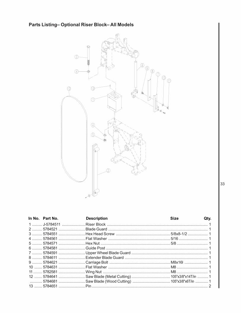
33
Parts Listing– Optional Riser Block– All Models
In No. Part No. Description Size Qty.1 ......... J-5784511 .....................Riser Block ........................................................................................... 12 ......... 5784521 ........................Blade Guard .......................................................................................... 13 ......... 5784551 ........................Hex Head Screw ................................................. 5/8x8-1/2 .................. 14 ......... 5784561 ........................Flat Washer ........................................................ 5/16 .......................... 15 ......... 5784571 ........................Hex Nut ............................................................... 5/8 ............................ 16 ......... 5784581 ........................Guide Post ............................................................................................ 17 ......... 5784591 ........................Upper Wheel Blade Guard ..................................................................... 18 ......... 5784611 ........................Extender Blade Guard ........................................................................... 19 ......... 5784621 ........................Carriage Bolt ....................................................... M8x16l ..................... 110 ....... 5784631 ........................Flat Washer ........................................................ M8 ............................ 111 ........ 5782581 ........................Wing Nut ............................................................. M8 ............................ 112 ....... 5784641 ........................Saw Blade (Metal Cutting) ................................... 105"x3/8"x14T/in ........... 1........... 5784681 ........................Saw Blade (Wood Cutting) .................................. 105"x3/8"x6T/in ............. 1
13 ....... 5784651 ........................Pin ......................................................................................................... 2
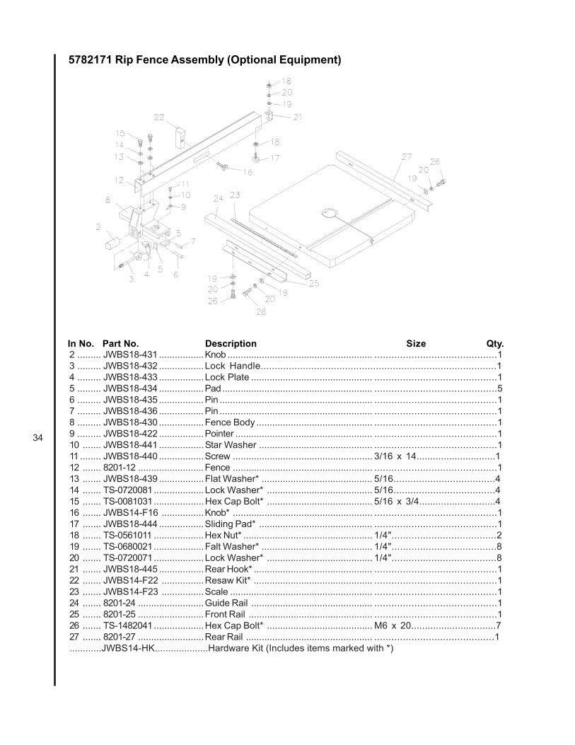
34
5782171 Rip Fence Assembly (Optional Equipment)
In No. Part No. Description Size Qty.2 ......... JWBS18-431 .................Knob ....................................................... ...........................................13 ......... JWBS18-432 .................Lock Handle....................................................................................14 ......... JWBS18-433 .................Lock Plate .............................................. ...........................................15 ......... JWBS18-434 .................Pad......................................................... ...........................................56 ......... JWBS18-435 .................Pin .......................................................... ...........................................17 ......... JWBS18-436 .................Pin .......................................................... ...........................................18 ......... JWBS18-430 .................Fence Body ............................................ ...........................................19 ......... JWBS18-422 .................Pointer .................................................... ...........................................110 ....... JWBS18-441 .................Star Washer ........................................... ...........................................111 ........ JWBS18-440 .................Screw ..................................................... 3/16 x 14.............................112 ....... 8201-12 .........................Fence ..................................................... ...........................................113 ....... JWBS18-439 .................Flat Washer* .......................................... 5/16....................................414 ....... TS-0720081...................Lock Washer* ........................................ 5/16....................................415 ....... TS-0081031...................Hex Cap Bolt* ........................................ 5/16 x 3/4............................416 ....... JWBS14-F16 ................Knob* ..................................................... ...........................................117 ....... JWBS18-444 .................Sliding Pad* ........................................... ...........................................118 ....... TS-0561011 ...................Hex Nut* ................................................. 1/4".....................................219 ....... TS-0680021...................Falt Washer* .......................................... 1/4".....................................820 ....... TS-0720071...................Lock Washer* ........................................ 1/4".....................................821 ....... JWBS18-445 .................Rear Hook* ............................................. ...........................................122 ....... JWBS14-F22 ................Resaw Kit* ............................................. ...........................................123 ....... JWBS14-F23 ................Scale ...................................................... ...........................................124 ....... 8201-24 .........................Guide Rail .............................................. ...........................................125 ....... 8201-25 .........................Front Rail ............................................... ...........................................126 ....... TS-1482041...................Hex Cap Bolt* ........................................ M6 x 20...............................727 ....... 8201-27 .........................Rear Rail ................................................ ..........................................1............JWBS14-HK....................Hardware Kit (Includes items marked with *)
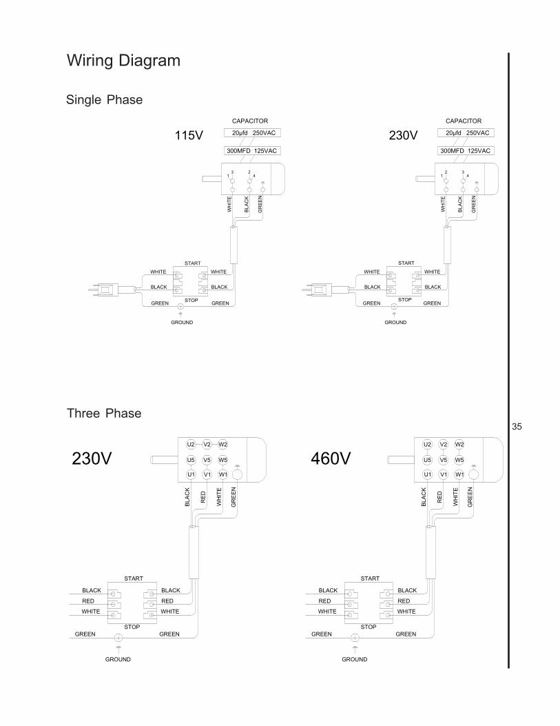
35
Wiring Diagram
13 2
4
WH
ITE
BLA
CK
GR
EEN
GROUND
GREEN
BLACK
WHITE
GREEN
BLACK
WHITE
START
STOP
300MFD 125VAC
20µfd 250VAC
CAPACITOR
115V
132
4
WH
ITE
BLA
CK
GR
EEN
GROUND
GREEN
BLACK
WHITE
GREEN
BLACK
WHITE
START
STOP
300MFD 125VAC
20µfd 250VAC
CAPACITOR
230V
U2
WH
ITE
RED
GR
EE
N
GROUND
GREEN GREEN
BLACK
WHITE
START
STOP
230V 460V
BLA
CK
V2 W2
W5
W1V1
V5U5
U1
RED
BLACK
WHITE
RED
U2
WH
ITE
RED
GR
EE
N
GROUND
GREEN GREEN
BLACK
WHITE
START
STOP
BLA
CK
V2 W2
W5
W1V1
V5U5
U1
RED
BLACK
WHITE
RED
Single Phase
Three Phase

WMH TOOL GROUP, Inc.427 New Sanford Road
LaVergne, Tennessee 30786Ph: 800-274-6848
www.wmhtoolgroup.com