Embed Size (px)
Citation preview

Operating Instructions and Parts Manual 10" Sliding Dual Bevel Compound Miter Saw Benchtop Series – Model No. JMS-10SCMS
JET 427 New Sanford Road LaVergne, Tennessee 37086 Part No. M-707110 Ph.: 800-274-6848 Revision B3 05/2014 www.jettools.com Copyright © 2014 JET
C US
R
174315
2
Warranty and Service JET warrants every product it sells against manufacturers’ defects. If one of our tools needs service or repair, please contact Technical Service by calling 1-800-274-6846, 8AM to 5PM CST, Monday through Friday.
Warranty Period The general warranty lasts for the time period specified in the literature included with your product or on the official JET branded website.
• JET products carry a limited warranty which varies in duration based upon the product. (See chart below) • Accessories carry a limited warranty of one year from the date of receipt. • Consumable items are defined as expendable parts or accessories expected to become inoperable within a
reasonable amount of use and are covered by a 90 day limited warranty against manufacturer’s defects.
Who is Covered This warranty covers only the initial purchaser of the product from the date of delivery.
What is Covered This warranty covers any defects in workmanship or materials subject to the limitations stated below. This warranty does not cover failures due directly or indirectly to misuse, abuse, negligence or accidents, normal wear-and-tear, improper repair, alterations or lack of maintenance.
Warranty Limitations Woodworking products with a Five Year Warranty that are used for commercial or industrial purposes default to a Two Year Warranty. Please contact Technical Service at 1-800-274-6846 for further clarification.
How to Get Technical Support Please contact Technical Service by calling 1-800-274-6846. Please note that you will be asked to provide proof of initial purchase when calling. If a product requires further inspection, the Technical Service representative will explain and assist with any additional action needed. JET has Authorized Service Centers located throughout the United States. For the name of an Authorized Service Center in your area call 1-800-274-6846 or use the Service Center Locator on the JET website.
More Information JET is constantly adding new products. For complete, up-to-date product information, check with your local distributor or visit the JET website.
How State Law Applies This warranty gives you specific legal rights, subject to applicable state law.
Limitations on This Warranty JET LIMITS ALL IMPLIED WARRANTIES TO THE PERIOD OF THE LIMITED WARRANTY FOR EACH PRODUCT. EXCEPT AS STATED HEREIN, ANY IMPLIED WARRANTIES OF MERCHANTABILITY AND FITNESS FOR A PARTICULAR PURPOSE ARE EXCLUDED. SOME STATES DO NOT ALLOW LIMITATIONS ON HOW LONG AN IMPLIED WARRANTY LASTS, SO THE ABOVE LIMITATION MAY NOT APPLY TO YOU. JET SHALL IN NO EVENT BE LIABLE FOR DEATH, INJURIES TO PERSONS OR PROPERTY, OR FOR INCIDENTAL, CONTINGENT, SPECIAL, OR CONSEQUENTIAL DAMAGES ARISING FROM THE USE OF OUR PRODUCTS. SOME STATES DO NOT ALLOW THE EXCLUSION OR LIMITATION OF INCIDENTAL OR CONSEQUENTIAL DAMAGES, SO THE ABOVE LIMITATION OR EXCLUSION MAY NOT APPLY TO YOU. JET sells through distributors only. The specifications listed in JET printed materials and on official JET website are given as general information and are not binding. JET reserves the right to effect at any time, without prior notice, those alterations to parts, fittings, and accessory equipment which they may deem necessary for any reason whatsoever. JET® branded products are not sold in Canada by JPW Industries, Inc.
Product Listing with Warranty Period 90 Days – Parts; Consumable items; Light-Duty Air Tools 1 Year – Motors; Machine Accessories; Heavy-Duty Air Tools; Pro-Duty Air Tools 2 Year – Metalworking Machinery; Electric Hoists, Electric Hoist Accessories; Woodworking Machinery used for industrial or commercial purposes 5 Year – Woodworking Machinery Limited Lifetime – JET Parallel clamps; VOLT Series Electric Hoists; Manual Hoists; Manual Hoist Accessories; Shop Tools; Warehouse & Dock products; Hand Tools
NOTE: JET is a division of JPW Industries, Inc. References in this document to JET also apply to JPW Industries, Inc., or any of its successors in interest to the JET brand.

3
Table of Contents Warranty and Service .................................................................................................................................... 2 Table of Contents .......................................................................................................................................... 3 Warnings ....................................................................................................................................................... 4 Compound Miter Saw Safety .......................................................................................................................... 6 Introduction .................................................................................................................................................... 7 Specifications ................................................................................................................................................ 7 Cutting Capacity ............................................................................................................................................ 7 Electrical ........................................................................................................................................................ 8 Features ........................................................................................................................................................ 9 Shipping Contents ....................................................................................................................................... 10 Assembly ..................................................................................................................................................... 10 Adjustments ................................................................................................................................................. 14 Operation..................................................................................................................................................... 19 Crown Molding Chart ................................................................................................................................... 26 Maintenance ................................................................................................................................................ 27 Troubleshooting – Motor .............................................................................................................................. 28 Troubleshooting – Operation ........................................................................................................................ 28 Parts ............................................................................................................................................................ 29 Wiring Diagram ............................................................................................................................................ 36
The specifications in this manual are given as general information and are not binding. JET reserves the right to effect, at any time and without prior notice, changes or alterations to parts, fittings, and accessory equipment deemed necessary for any reason whatsoever.

4
Warnings 1. Read and understand the entire owners' manual before attempting assembly or operation.
2. Read and understand the warnings posted on the machine and in this manual. Failure to comply with all of these warnings may cause serious injury.
3. Replace the warning labels if they become obscured or removed.
4. This saw is designed and intended for use by properly trained and experienced personnel only. If you are not familiar with the proper and safe operation of a compound miter saw, do not use until proper training and knowledge have been obtained.
5. Do not use this saw for other than its intended use. If used for other purposes, JET disclaims any real or implied warranty and holds itself harmless from any injury that may result from that use.
6. Always wear approved safety glasses/face shields while using this miter saw. Everyday eyeglasses only have impact resistant lenses; they are not safety glasses.
7. Before operating this saw, remove tie, rings, watches and other jewelry, and roll sleeves up past the elbows. Remove all loose clothing and confine long hair. Non-slip footwear or anti-skid floor strips are recommended. Do not wear gloves.
8. Wear ear protectors (plugs or muffs) during extended periods of operation.
9. Some dust created by power sanding, sawing, grinding, drilling and other construction activities contain chemicals known to cause cancer, birth defects or other reproductive harm. Some examples of these chemicals are:
• Lead from lead based paint.
• Crystalline silica from bricks, cement and other masonry products.
• Arsenic and chromium from chemically treated lumber.
Your risk of exposure varies, depending on how often you do this type of work. To reduce your exposure to these chemicals, work in a well-ventilated area and work with approved safety equipment, such as face or dust masks that are specifically designed to filter out microscopic particles.
10. Do not operate this machine while tired or under the influence of drugs, alcohol or any medication.
11. Make certain the switch is in the OFF position before connecting the machine to the power supply.
12. Make certain the machine is properly grounded.
13. Make all machine adjustments or maintenance with the machine unplugged from the power source.
14. Remove adjusting keys and wrenches. Form a habit of checking to see that keys and adjusting wrenches are removed from the machine before turning it on.
15. Keep safety guards in place at all times when the machine is in use. If removed for maintenance purposes, use extreme caution and replace the guards immediately.
16. Make sure this machine is firmly secured to the floor or bench before use.
17. Check damaged parts. Before further use of the machine, a guard or other part that is damaged should be carefully checked to determine that it will operate properly and perform its intended function. Check for alignment of moving parts, binding of moving parts, breakage of parts, mounting and any other conditions that may affect its operation. A guard or other part that is damaged should be properly repaired or replaced.
18. Provide for adequate space surrounding work area and non-glare, overhead lighting.
19. Keep the floor around the machine clean and free of scrap material, oil and grease.
20. Don't use in dangerous environment. Don't use power tools in damp or wet locations, or expose them to rain. Keep work area well lighted.
5
21. Keep visitors a safe distance from the work area. Keep children away.
22. Make your workshop child proof with padlocks, master switches or by removing starter keys.
23. Give your work undivided attention. Looking around, carrying on a conversation and “horse-play” are careless acts that can result in serious injury.
24. Maintain a balanced stance at all times so that you do not fall or lean against the blade or other moving parts. Do not overreach or use excessive force to perform any machine operation.
25. Use the right tool at the correct speed and feed rate. Do not force a tool or attachment to do a job for which it was not designed. The right tool will do the job better and safer.
26. Use recommended accessories; improper accessories may be hazardous.
27. Maintain tools with care. Keep saw blades sharp and clean for the best and safest performance. Follow instructions for lubricating and changing accessories.
28. Disconnect tools before servicing and when changing accessories such as blades.
29. Make sure the work piece is securely attached or clamped to the table.
30. Turn off the machine before cleaning. Use a brush or compressed air to remove chips or debris — do not use your hands.
31. Do not stand on the machine. Serious injury could occur if the machine tips over.
32. Never leave the machine running unattended. Turn the power off and do not leave the machine until it comes to a complete stop.
33. Remove loose items and unnecessary work pieces from the area before starting the machine.
Familiarize yourself with the following safety notices used in this manual:
This means that if precautions are not heeded, it may result in minor injury and/or possible machine damage.
This means that if precautions are not heeded, it may result in serious injury or possibly even death.

6
Compound Miter Saw Safety Specific safety instructions for this compound miter saw:
1. Do not operate the miter saw until it is completely assembled and installed according to these instructions.
2. If you are not thoroughly familiar with the operation of miter saws, seek guidance from your supervisor, instructor or other qualified person.
3. Always hold the work firmly against the fence and table.
4. Do not perform any operation free hand (use clamp wherever possible).
5. Keep hands out of the path of the saw blade. If the workpiece you are cutting would cause your hands to be within 8-3/4 in. of the saw blade, the workpiece should be clamped in place before making the cut.
6. Be sure the blade is sharp, runs freely and is free of vibration.
7. Allow the motor to come up to full speed before starting a cut.
8. Keep the motor air slots clean and free of chips or dust.
9. Always make sure all handles are tight before cutting, even if the table is positioned in one of the positive stops.
10. Be sure both the blade and the collar are clean and the arbor bolt is tightened securely.
11. Use only blade collars specified for your saw.
12. Never use blades larger in diameter than 10 inches.
13. Never apply lubricants to the blade when it is running.
14. Always check the blade for cracks or damage before operation. Replace a cracked or damaged blade immediately.
15. Never use blades recommended for operation at less than 4200 RPM.
16. Always keep the blade guards in place and use at all times.
17. Never reach around the saw blade.
18. Make sure the blade is not contacting the workpiece before the switch is turned ON.
19. Important: After completing the cut, release the trigger and wait for the blade to stop before returning the saw to the raised position.
20. Make sure the blade has come to a complete stop before removing or securing the workpiece, changing the workpiece angle or changing the angle of the blade.
21. Never cut metals or masonry products with this tool. This miter saw is designed for use on wood and wood-like products.
22. Never cut small pieces. If the workpiece being cut would cause your hand or fingers to be within 8-3/4 in. of the saw blade the workpiece is too small.
23. Provide adequate support to the sides of the saw table for long work pieces.
24. Never use the miter saw in an area with flammable liquids or gases.
25. Never use solvents to clean plastic parts. Solvents could possibly dissolve or otherwise damage the material.
26. Shut off the power before servicing or adjusting the tool.
27. Disconnect the saw from the power source and clean the machine when finished using.
28. Make sure the work area is clean before leaving the machine.
29. Should any part of your miter saw be missing, damaged, or fail in any way, or any electrical component fail to perform properly, lock the switch and remove the plug from the power supply outlet. Replace missing, damaged, or failed parts before resuming operation.

7
Introduction This manual is provided by JET covering the safe operation and maintenance procedures for the JET Model JMS-10SCMS Dual Bevel Sliding Compound Miter Saw with laser. This manual contains instructions on installation, safety precautions, general operating procedures, maintenance instructions and parts breakdown. This machine has been designed and constructed to provide years of trouble free operation if used in accordance with instructions set forth in this manual. If there are any questions or comments, please contact either your local supplier or JET. JET can also be reached at our web site: www.jettools.com.
Specifications Model Number ..................................................................................................................... JMS-10SCMS Stock Number................................................................................................................................ 707110 Motor ............................................................................................................................... 120V, 60Hz, 15A No Load Speed (Arbor) ............................................................................................................... 4200RPM Motor Arbor Shaft Size ........................................................................................................................ 5/8" Blade .................................................................................................................... 10", 40T, carbide tipped Blade Arbor Size ................................................................................................................................. 5/8" Miter Stops .................................................................................................................10 stops, -45° to 60° Bevel Stops ................................................................................................. 0°, 33.9° and 45° left and right Base Dimensions (WxD) .................................................................................................. 37-1/2” x 26-1/4” Footprint, without optional extensions (WxD)* .............................................................................. 41” x 42” Cord Length ....................................................................................................................................... 7’-6” Net Weight ...................................................................................................................................... 51 lbs. Shipping Weight .............................................................................................................................. 56 lbs. * Space required for full range of miter, bevel and slide motions
The above specifications were current at the time this manual was published, but because of our policy of continuous improvement, JET reserves the right to change specifications at any time and without prior notice, without incurring obligations.
Cutting Capacity Cut Type Miter Angle Bevel Angle Cutting Capacity
Cross Cut 0º 0º 3-5/8" x 12"
Miter 45º Right & Left 0º 3-5/8" x 8"
Miter 60º Right 0º 3-5/8" x 5-3/4"
Bevel 0º 45º Left 1-5/8" x 12"
Bevel 0º 45º Right 1-3/8" x 12"
Compound Cut 45º Right & Left 45º Left 1-5/8" x 8"
Compound Cut 45º Right & Left 45º Right 1-3/8" x 8"
Compound Cut 60º Right 45º Right 1-3/8" x 5-3/4"
Vertical Capacity (Baseboard) 0º 0º 4-3/4"
Read and understand the entire contents of this manual before attempting assembly or operation! Failure to comply may cause serious injury!
8
Electrical Power Supply and Motor Specifications The AC motor used in this saw is a universal, nonreversible type (see Motor in the Specifica-tions section on page 7).
To avoid electrical hazards, fire hazards, or damage to the machine, use proper circuit protection. Your saw is wired at the factory for 120V operation. Connect to a 120V, 15 Amp circuit and use a 15 amp time delay fuse or circuit breaker. If power cord is worn or cut, or damaged in any way, have it replaced immediately to avoid shock or fire.
Electrical Requirements This machine is double insulated to provide a double thickness of insulation between the user and the machine's electrical system. All exposed metal parts are isolated from the internal metal motor components with protective insulation.
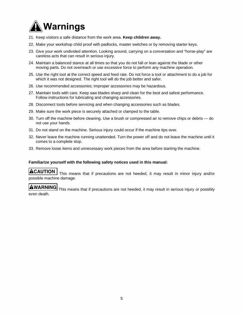
This saw has a plug that looks like the one shown in Figure A.
Figure A
To reduce the risk of electrical shock, this saw has a polarized plug (one blade is wider than the other). This plug will fit in a polarized outlet only one way; if the plug does not fit fully in the outlet, reverse the plug. If it still does not fit, contact a qualified electrician to install the proper outlet. Do not change the plug in any way.
Double insulation does not take the place of normal safety precautions when operating this tool.
To avoid electrocution:
1. Use only identical replacement parts when servicing a tool with double insulation. Servicing should be performed by a qualified technician.
2. Do not use power tools in wet or damp locations or expose them to rain or snow.
Extension Cords Make sure your extension cord is in good condition. When using an extension cord, be sure to use one heavy enough to carry the current your machine will draw. An undersized cord will cause a drop in the line voltage resulting in power loss and overheating. The table below shows the correct size to use depending on the cord length and nameplate ampere rating. If in doubt, use the next heavier gauge. Remember, the smaller the gauge number, the heavier the cord.
Cord Length AWG 00 – 25ft 016 25 – 50ft 014
Important: Make certain the receptacle in question is properly grounded. If you are not sure, have a registered electrician check the receptacle.
9
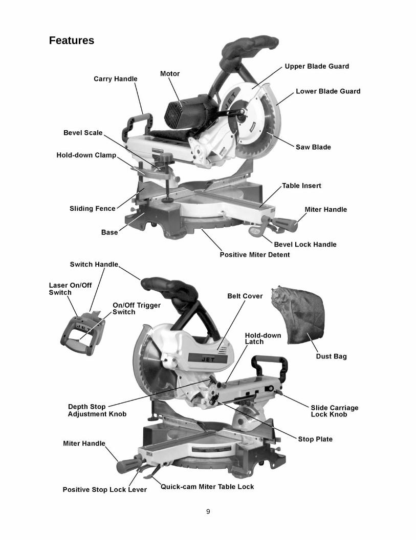
Features
10
Shipping Contents Unpacking
1. Remove the contents from the shipping container.
2. Compare the contents of the shipping container with the list found below. Make certain that all items are accounted for before discarding any packing material. Report any shortages or damage to your JET distributor.
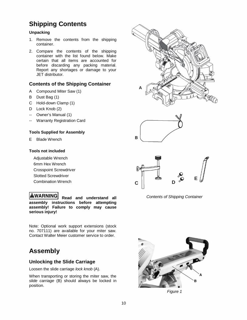
Contents of the Shipping Container A Compound Miter Saw (1) B Dust Bag (1) C Hold-down Clamp (1) D Lock Knob (2) -- Owner’s Manual (1) -- Warranty Registration Card Tools Supplied for Assembly
E Blade Wrench Tools not included
00Adjustable Wrench 006mm Hex Wrench 00Crosspoint Screwdriver 00Slotted Screwdriver 00Combination Wrench
Read and understand all assembly instructions before attempting assembly! Failure to comply may cause serious injury!
Note: Optional work support extensions (stock no. 707111) are available for your miter saw. Contact Walter Meier customer service to order.
Assembly Unlocking the Slide Carriage Loosen the slide carriage lock knob (A).
When transporting or storing the miter saw, the slide carriage (B) should always be locked in position.
C DE
Contents of Shipping Container
Figure 1
11
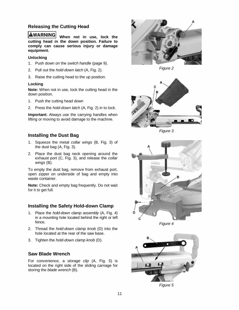
Releasing the Cutting Head
When not in use, lock the cutting head in the down position. Failure to comply can cause serious injury or damage equipment.
Unlocking 1. Push down on the switch handle (page 9).
2. Pull out the hold-down latch (A, Fig. 2).
3. Raise the cutting head to the up position.
Locking Note: When not in use, lock the cutting head in the down position.
1. Push the cutting head down
2. Press the hold-down latch (A, Fig. 2) in to lock.
Important: Always use the carrying handles when lifting or moving to avoid damage to the machine.
Installing the Dust Bag 1. Squeeze the metal collar wings (B, Fig. 3) of
the dust bag (A, Fig. 3).
2. Place the dust bag neck opening around the exhaust port (C, Fig. 3), and release the collar wings (B).
To empty the dust bag, remove from exhaust port, open zipper on underside of bag and empty into waste container.
Note: Check and empty bag frequently. Do not wait for it to get full.
Installing the Safety Hold-down Clamp 1. Place the hold-down clamp assembly (A, Fig. 4)
in a mounting hole located behind the right or left fence.
2. Thread the hold-down clamp knob (D) into the hole located at the rear of the saw base.
3. Tighten the hold-down clamp knob (D).
Saw Blade Wrench For convenience, a storage clip (A, Fig. 5) is located on the right side of the sliding carriage for storing the blade wrench (B).
Figure 2
Figure 3
Figure 4
Figure 5
12
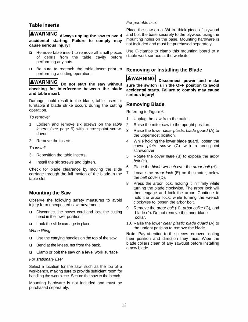
Table Inserts
Always unplug the saw to avoid accidental starting. Failure to comply may cause serious injury!
Remove table insert to remove all small pieces of debris from the table cavity before performing any cuts.
Be sure to reattach the table insert prior to performing a cutting operation.
Do not start the saw without checking for interference between the blade and table insert.
Damage could result to the blade, table insert or turntable if blade strike occurs during the cutting operation.
To remove:
1. Loosen and remove six screws on the table inserts (see page 9) with a crosspoint screw-driver
2. Remove the inserts.
To install:
3. Reposition the table inserts.
4. Install the six screws and tighten.
Check for blade clearance by moving the slide carriage through the full motion of the blade in the table slot.
Mounting the Saw Observe the following safety measures to avoid injury form unexpected saw movement:
Disconnect the power cord and lock the cutting head in the lower position.
Lock the slide carriage in place.
When lifting:
Use the carrying handles on the top of the saw.
Bend at the knees, not from the back.
Clamp or bolt the saw on a level work surface.
For stationary use:
Select a location for the saw, such as the top of a workbench, making sure to provide sufficient room for handling the workpiece. Secure the saw to the bench
Mounting hardware is not included and must be purchased separately.
For portable use:
Place the saw on a 3/4 in. thick piece of plywood and bolt the base securely to the plywood using the mounting holes on the base. Mounting hardware is not included and must be purchased separately.
Use C-clamps to clamp this mounting board to a stable work surface at the worksite.
Removing or Installing the Blade
Disconnect power and make sure the switch is in the OFF position to avoid accidental starts. Failure to comply may cause serious injury!
Removing Blade Referring to Figure 6:
1. Unplug the saw from the outlet. 2. Raise the miter saw to the upright position. 3. Raise the lower clear plastic blade guard (A) to
the uppermost position. 4. While holding the lower blade guard, loosen the
cover plate screw (C) with a crosspoint screwdriver.
5. Rotate the cover plate (B) to expose the arbor bolt (H).
6. Place the blade wrench over the arbor bolt (H). 7. Locate the arbor lock (E) on the motor, below
the belt cover (D). 8. Press the arbor lock, holding it in firmly while
turning the blade clockwise. The arbor lock will then engage and lock the arbor. Continue to hold the arbor lock, while turning the wrench clockwise to loosen the arbor bolt.
9. Remove the arbor bolt (H), arbor collar (G), and blade (J). Do not remove the inner blade collar.
10. Raise the lower clear plastic blade guard (A) to the upright position to remove the blade.
Note: Pay attention to the pieces removed, noting their position and direction they face. Wipe the blade collars clean of any sawdust before installing a new blade.
13
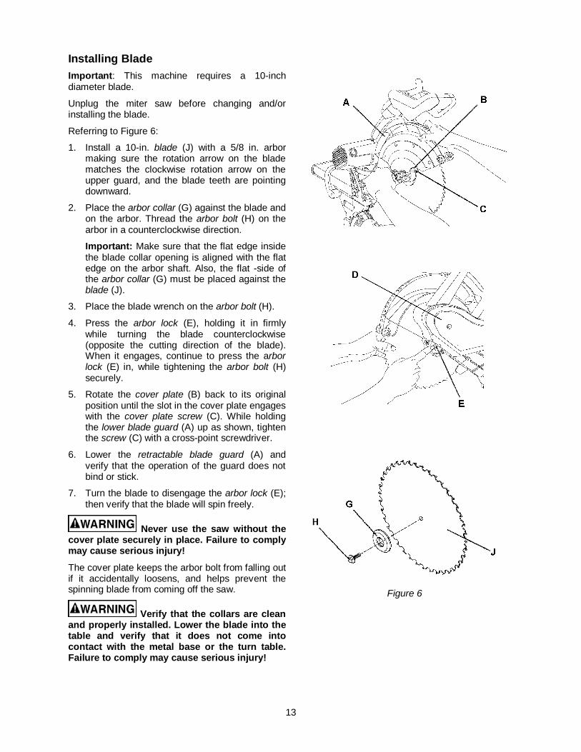
Installing Blade Important: This machine requires a 10-inch diameter blade.
Unplug the miter saw before changing and/or installing the blade.
Referring to Figure 6:
1. Install a 10-in. blade (J) with a 5/8 in. arbor making sure the rotation arrow on the blade matches the clockwise rotation arrow on the upper guard, and the blade teeth are pointing downward.
2. Place the arbor collar (G) against the blade and on the arbor. Thread the arbor bolt (H) on the arbor in a counterclockwise direction.
Important: Make sure that the flat edge inside the blade collar opening is aligned with the flat edge on the arbor shaft. Also, the flat -side of the arbor collar (G) must be placed against the blade (J).
3. Place the blade wrench on the arbor bolt (H).
4. Press the arbor lock (E), holding it in firmly while turning the blade counterclockwise (opposite the cutting direction of the blade). When it engages, continue to press the arbor lock (E) in, while tightening the arbor bolt (H) securely.
5. Rotate the cover plate (B) back to its original position until the slot in the cover plate engages with the cover plate screw (C). While holding the lower blade guard (A) up as shown, tighten the screw (C) with a cross-point screwdriver.
6. Lower the retractable blade guard (A) and verify that the operation of the guard does not bind or stick.
7. Turn the blade to disengage the arbor lock (E); then verify that the blade will spin freely.
Never use the saw without the cover plate securely in place. Failure to comply may cause serious injury!
The cover plate keeps the arbor bolt from falling out if it accidentally loosens, and helps prevent the spinning blade from coming off the saw.
Verify that the collars are clean and properly installed. Lower the blade into the table and verify that it does not come into contact with the metal base or the turn table. Failure to comply may cause serious injury!
Figure 6

14
Adjustments Before attempting any adjust-
ments – To avoid injury from unexpected starting or electrical shock make sure the trigger is released and remove the power cord from the power source. Failure to comply may cause serious injury! Note: Your miter saw was adjusted at the factory. However, during shipment slight misalignment may have occurred. Check the following settings and adjust if necessary prior to using this miter saw.
Bevel Stop Adjustments 90°(0°) Bevel Adjustment 1. Set the miter angle to 0°.
Note: A bevel angle of 0° corresponds to a blade-to-miter-table angle of 90°.
2. Turn the bevel lock handle (A, Fig. 8) clockwise to loosen and tilt the cutting arm while pushing the bevel detent pin (E, Fig. 10) in against the 0° bevel stop. Turn the bevel lock handle (A, Fig. 8) counterclockwise to tighten.
3. Place a combination square on the miter table with the rule against the table and heel of the square against the saw blade.
If the blade is not 0° to the miter table:
4. Using a 4mm hex wrench, loosen four adjustment screws (B, Fig. 9) at the back of the miter saw. Pull the bevel detent pin (E, Fig. 10) out fully.
5. Unlock the bevel lock handle (A, Fig. 8) and position the cutting arm to be zero degrees to the table using the combination square as your reference.
6. When the blade is at zero degrees to the table, turn the bevel lock handle (A, Fig. 8) clockwise to tighten.
7. Push in the bevel detent pin (E, Fig. 10). If the pin doesn’t slide in, the anchor plate needs to be shifted. To do this, move the adjustment screws (B, Fig. 9) in their slots until the bevel detent pin slides in.
8. Now slide the adjustment screws (B, Fig. 9) until the anchor plate rests against the bevel detent pin. Tighten the four adjustment screws. (B, Fig. 9). Note: Use the screws to hold the anchor plate against the detent pin while tightening the screws, to prevent slack occurring during the tightening process.
Figure 8
Figure 9
Figure 10
15
9. Test the 90° alignment as follows: Unlock bevel lock handle (A, Fig. 8), and pull out bevel detent pin (E, Fig. 10). Rotate head left or right, push in bevel detent pin, and bring head back to vertical to contact the detent pin. Re-check blade with the square. If needed, repeat the above procedure to get accurate alignment.
Bevel Scale Indicators 1. Set the blade to be exactly 90° (0°) to the table.
2. With cross-point screwdriver, loosen two bevel indicator screws (C, Fig. 10).
3. Adjust bevel indicators (D, Fig. 10) to the “0” mark on the bevel scale and retighten the screws (C, Fig. 10).
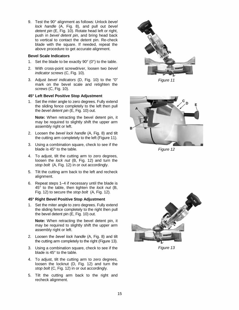
45° Left Bevel Positive Stop Adjustment 1. Set the miter angle to zero degrees. Fully extend
the sliding fence completely to the left then pull the bevel detent pin (E, Fig. 10) out.
Note: When retracting the bevel detent pin, it may be required to slightly shift the upper arm assembly right or left.
2. Loosen the bevel lock handle (A, Fig. 8) and tilt the cutting arm completely to the left (Figure 11).
3. Using a combination square, check to see if the blade is 45° to the table.
4. To adjust, tilt the cutting arm to zero degrees, loosen the lock nut (B, Fig. 12) and turn the stop bolt (A, Fig. 12) in or out accordingly.
5. Tilt the cutting arm back to the left and recheck alignment.
6. Repeat steps 1–4 if necessary until the blade is 45° to the table, then tighten the lock nut (B, Fig. 12) to secure the stop bolt (A, Fig. 12).
45° Right Bevel Positive Stop Adjustment 1. Set the miter angle to zero degrees. Fully extend
the sliding fence completely to the right then pull the bevel detent pin (E, Fig. 10) out.
Note: When retracting the bevel detent pin, it may be required to slightly shift the upper arm assembly right or left.
2. Loosen the bevel lock handle (A, Fig. 8) and tilt the cutting arm completely to the right (Figure 13).
3. Using a combination square, check to see if the blade is 45° to the table.
4. To adjust, tilt the cutting arm to zero degrees, loosen the locknut (D, Fig. 12) and turn the stop bolt (C, Fig. 12) in or out accordingly.
5. Tilt the cutting arm back to the right and recheck alignment.
Figure 11
Figure 12
Figure 13
16
6. Repeat steps 1–4 if necessary until the blade is 45° to the table, then tighten the lock nut (D, Fig. 12) to secure the stop bolt (C, Fig. 12).
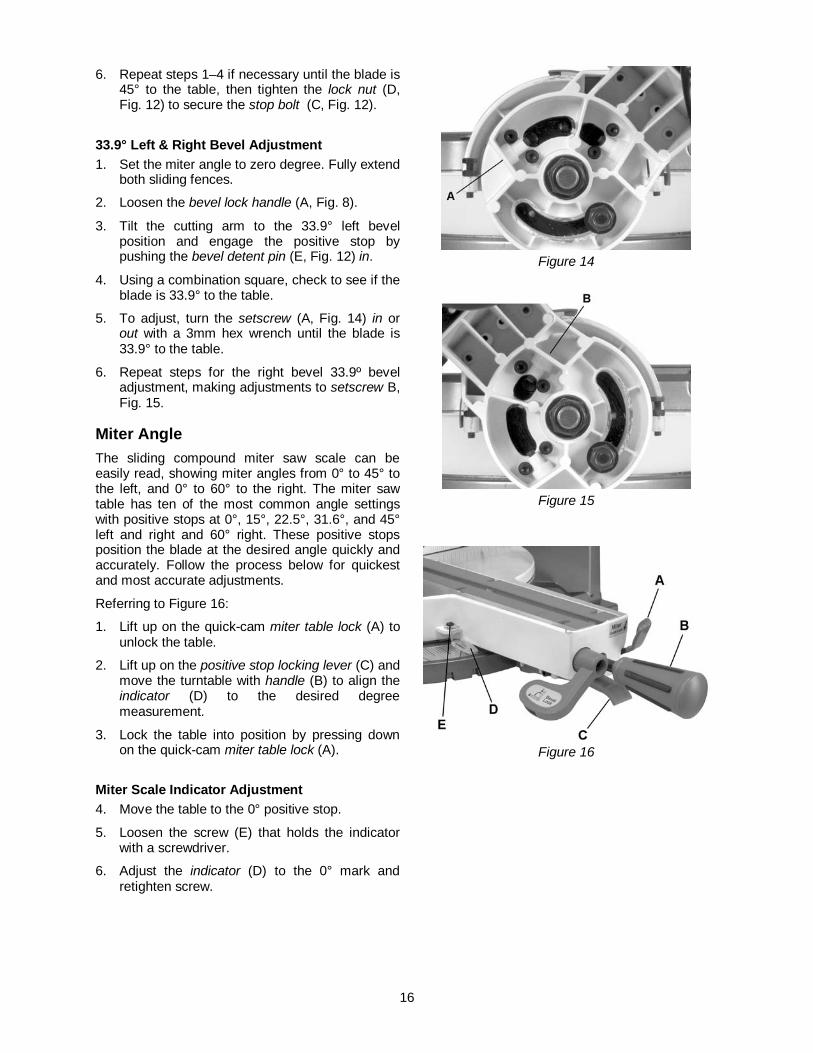
33.9° Left & Right Bevel Adjustment 1. Set the miter angle to zero degree. Fully extend
both sliding fences.
2. Loosen the bevel lock handle (A, Fig. 8).
3. Tilt the cutting arm to the 33.9° left bevel position and engage the positive stop by pushing the bevel detent pin (E, Fig. 12) in.
4. Using a combination square, check to see if the blade is 33.9° to the table.
5. To adjust, turn the setscrew (A, Fig. 14) in or out with a 3mm hex wrench until the blade is 33.9° to the table.
6. Repeat steps for the right bevel 33.9º bevel adjustment, making adjustments to setscrew B, Fig. 15.
Miter Angle The sliding compound miter saw scale can be easily read, showing miter angles from 0° to 45° to the left, and 0° to 60° to the right. The miter saw table has ten of the most common angle settings with positive stops at 0°, 15°, 22.5°, 31.6°, and 45° left and right and 60° right. These positive stops position the blade at the desired angle quickly and accurately. Follow the process below for quickest and most accurate adjustments.
Referring to Figure 16:
1. Lift up on the quick-cam miter table lock (A) to unlock the table.
2. Lift up on the positive stop locking lever (C) and move the turntable with handle (B) to align the indicator (D) to the desired degree measurement.
3. Lock the table into position by pressing down on the quick-cam miter table lock (A).
Miter Scale Indicator Adjustment 4. Move the table to the 0° positive stop.
5. Loosen the screw (E) that holds the indicator with a screwdriver.
6. Adjust the indicator (D) to the 0° mark and retighten screw.
Figure 14
Figure 15
Figure 16
17
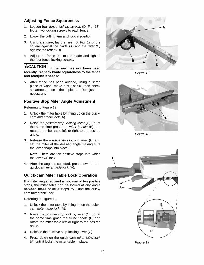
Adjusting Fence Squareness 1. Loosen four fence locking screws (D, Fig. 18).
Note: two locking screws to each fence.
2. Lower the cutting arm and lock in position.
3. Using a square, lay the heel (B, Fig. 17 of the square against the blade (A) and the ruler (C) against the fence (D).
4. Adjust the fence 90° to the blade and tighten the four fence locking screws.
If the saw has not been used recently, recheck blade squareness to the fence and readjust if needed.
5. After fence has been aligned, using a scrap piece of wood, make a cut at 90º then check squareness on the piece. Readjust if necessary.
Positive Stop Miter Angle Adjustment Referring to Figure 19:
1. Unlock the miter table by lifting up on the quick-cam miter table lock (A).
2. Raise the positive stop locking lever (C) up; at the same time grasp the miter handle (B) and rotate the miter table left or right to the desired angle.
3. Release the positive stop locking lever (C) and set the miter at the desired angle making sure the lever snaps into place.
Note: There are ten positive stops into which the lever will lock.
4. After the angle is selected, press down on the quick-cam miter table lock (A).
Quick-cam Miter Table Lock Operation If a miter angle required is not one of ten positive stops, the miter table can be locked at any angle between these positive stops by using the quick-cam miter table lock.
Referring to Figure 19:
1. Unlock the miter table by lifting up on the quick-cam miter table lock (A).
2. Raise the positive stop locking lever (C) up; at the same time grasp the miter handle (B) and rotate the miter table left or right to the desired angle.
3. Release the positive stop locking lever (C).
4. Press down on the quick-cam miter table lock (A) until it locks the miter table in place.
Figure 17
Figure 18
Figure 19
18
Note: The quick-cam miter table lock should lock the table and prevent it from moving. If adjustment is needed, see Quick-cam Miter Table Lock Adjustment below.
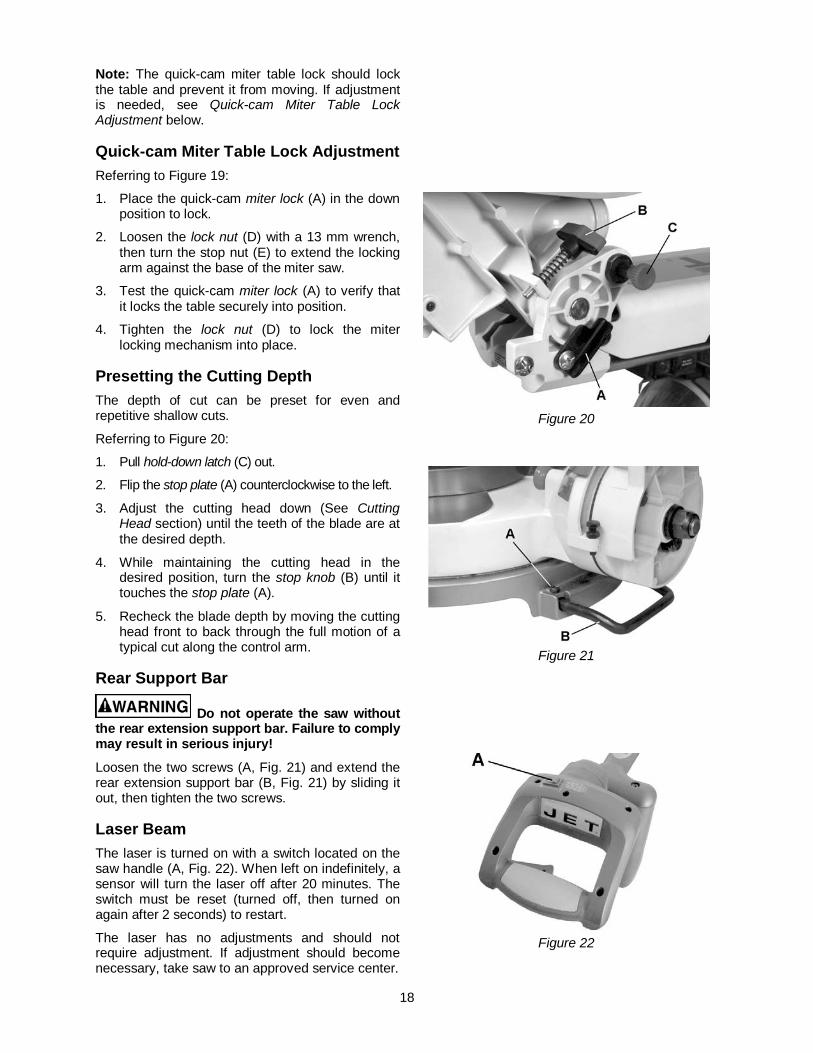
Quick-cam Miter Table Lock AdjustmentReferring to Figure 19:
1. Place the quick-cam miter lock (A) in the down position to lock.
2. Loosen the lock nut (D) with a 13 mm wrench, then turn the stop nut (E) to extend the locking arm against the base of the miter saw.
3. Test the quick-cam miter lock (A) to verify that it locks the table securely into position.
4. Tighten the lock nut (D) to lock the miter locking mechanism into place.
Presetting the Cutting Depth The depth of cut can be preset for even and repetitive shallow cuts.
Referring to Figure 20:
1. Pull hold-down latch (C) out.
2. Flip the stop plate (A) counterclockwise to the left.
3. Adjust the cutting head down (See Cutting Head section) until the teeth of the blade are at the desired depth.
4. While maintaining the cutting head in the desired position, turn the stop knob (B) until it touches the stop plate (A).
5. Recheck the blade depth by moving the cutting head front to back through the full motion of a typical cut along the control arm.
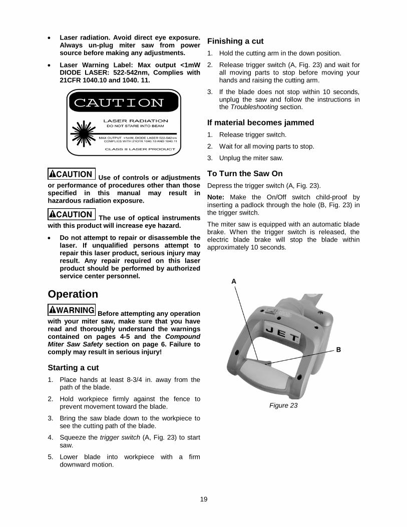
Rear Support Bar
Do not operate the saw without the rear extension support bar. Failure to comply may result in serious injury!
Loosen the two screws (A, Fig. 21) and extend the rear extension support bar (B, Fig. 21) by sliding it out, then tighten the two screws.
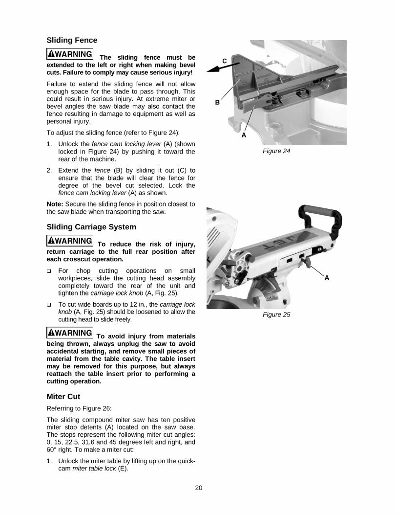
Laser Beam The laser is turned on with a switch located on the saw handle (A, Fig. 22). When left on indefinitely, a sensor will turn the laser off after 20 minutes. The switch must be reset (turned off, then turned on again after 2 seconds) to restart.
The laser has no adjustments and should not require adjustment. If adjustment should become necessary, take saw to an approved service center.
Figure 20
Figure 21
Figure 22
19
• Laser radiation. Avoid direct eye exposure. Always un-plug miter saw from power source before making any adjustments.
• Laser Warning Label: Max output <1mW DIODE LASER: 522-542nm, Complies with 21CFR 1040.10 and 1040. 11.
Use of controls or adjustments or performance of procedures other than those specified in this manual may result in hazardous radiation exposure.
The use of optical instruments with this product will increase eye hazard.
• Do not attempt to repair or disassemble the laser. If unqualified persons attempt to repair this laser product, serious injury may result. Any repair required on this laser product should be performed by authorized service center personnel.
Operation Before attempting any operation
with your miter saw, make sure that you have read and thoroughly understand the warnings contained on pages 4-5 and the Compound Miter Saw Safety section on page 6. Failure to comply may result in serious injury!
Starting a cut 1. Place hands at least 8-3/4 in. away from the
path of the blade.
2. Hold workpiece firmly against the fence to prevent movement toward the blade.
3. Bring the saw blade down to the workpiece to see the cutting path of the blade.
4. Squeeze the trigger switch (A, Fig. 23) to start saw.
5. Lower blade into workpiece with a firm downward motion.
Finishing a cut 1. Hold the cutting arm in the down position.
2. Release trigger switch (A, Fig. 23) and wait for all moving parts to stop before moving your hands and raising the cutting arm.
3. If the blade does not stop within 10 seconds, unplug the saw and follow the instructions in the Troubleshooting section.
If material becomes jammed 1. Release trigger switch.
2. Wait for all moving parts to stop.
3. Unplug the miter saw.
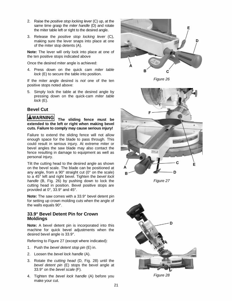
To Turn the Saw On Depress the trigger switch (A, Fig. 23).
Note: Make the On/Off switch child-proof by inserting a padlock through the hole (B, Fig. 23) in the trigger switch.
The miter saw is equipped with an automatic blade brake. When the trigger switch is released, the electric blade brake will stop the blade within approximately 10 seconds.
Figure 23
20
Sliding Fence
The sliding fence must be extended to the left or right when making bevel cuts. Failure to comply may cause serious injury!
Failure to extend the sliding fence will not allow enough space for the blade to pass through. This could result in serious injury. At extreme miter or bevel angles the saw blade may also contact the fence resulting in damage to equipment as well as personal injury.
To adjust the sliding fence (refer to Figure 24):
1. Unlock the fence cam locking lever (A) (shown locked in Figure 24) by pushing it toward the rear of the machine.
2. Extend the fence (B) by sliding it out (C) to ensure that the blade will clear the fence for degree of the bevel cut selected. Lock the fence cam locking lever (A) as shown.
Note: Secure the sliding fence in position closest to the saw blade when transporting the saw.
Sliding Carriage System
To reduce the risk of injury, return carriage to the full rear position after each crosscut operation.
For chop cutting operations on small workpieces, slide the cutting head assembly completely toward the rear of the unit and tighten the carriage lock knob (A, Fig. 25).
To cut wide boards up to 12 in., the carriage lock knob (A, Fig. 25) should be loosened to allow the cutting head to slide freely.
To avoid injury from materials being thrown, always unplug the saw to avoid accidental starting, and remove small pieces of material from the table cavity. The table insert may be removed for this purpose, but always reattach the table insert prior to performing a cutting operation.
Miter Cut Referring to Figure 26:
The sliding compound miter saw has ten positive miter stop detents (A) located on the saw base. The stops represent the following miter cut angles: 0, 15, 22.5, 31.6 and 45 degrees left and right, and 60° right. To make a miter cut:
1. Unlock the miter table by lifting up on the quick-cam miter table lock (E).
Figure 24
Figure 25
21
2. Raise the positive stop locking lever (C) up, at the same time grasp the miter handle (D) and rotate the miter table left or right to the desired angle.
3. Release the positive stop locking lever (C), making sure the lever snaps into place at one of the miter stop detents (A).
Note: The lever will only lock into place at one of the ten positive stops indicated above
Once the desired miter angle is achieved:
4. Press down on the quick cam miter table lock (E) to secure the table into position.
If the miter angle desired is not one of the ten positive stops noted above:
5. Simply lock the table at the desired angle by pressing down on the quick-cam miter table lock (E).
Bevel Cut
The sliding fence must be extended to the left or right when making bevel cuts. Failure to comply may cause serious injury!
Failure to extend the sliding fence will not allow enough space for the blade to pass through. This could result in serious injury. At extreme miter or bevel angles the saw blade may also contact the fence resulting in damage to equipment as well as personal injury.
Tilt the cutting head to the desired angle as shown on the bevel scale. The blade can be positioned at any angle, from a 90° straight cut (0° on the scale) to a 45° left and right bevel. Tighten the bevel lock handle (B, Fig. 26) by pushing down to lock the cutting head in position. Bevel positive stops are provided at 0°, 33.9° and 45°.
Note: The saw comes with a 33.9° bevel detent pin for setting up crown molding cuts when the angle of the walls equals 90°.
33.9° Bevel Detent Pin for Crown Moldings Note: A bevel detent pin is incorporated into this machine for quick bevel adjustments when the desired bevel angle is 33.9°.
Referring to Figure 27 (except where indicated):
1. Push the bevel detent stop pin (E) in.
2. Loosen the bevel lock handle (A).
3. Rotate the cutting head (D, Fig. 28) until the bevel detent pin (E) stops the bevel angle at 33.9° on the bevel scale (F).
4. Tighten the bevel lock handle (A) before you make your cut.
Figure 26
Figure 27
Figure 28
22
Compound Cuts Referring to Figure 27:
Setting the bevel angle
1. Extend the fence by sliding it out to the required location (see Sliding Fence on page 22).
2. Loosen the bevel lock handle (A).
3. Set the desired bevel angle; then lock the bevel lock handle (A).
Setting the miter angle
4. Set the desired miter angle and lock into position. See Miter Cut.
5. Unlock the miter table by lifting up on the quick-cam miter table lock (D).
6. Raise the positive stop locking lever (C) up, at the same time grasp the miter handle (B) and rotate the miter table left or right to the desired angle.
7. Release the positive stop locking lever (C).
8. Lock the miter table by pressing down on the quick-cam miter table lock (D).
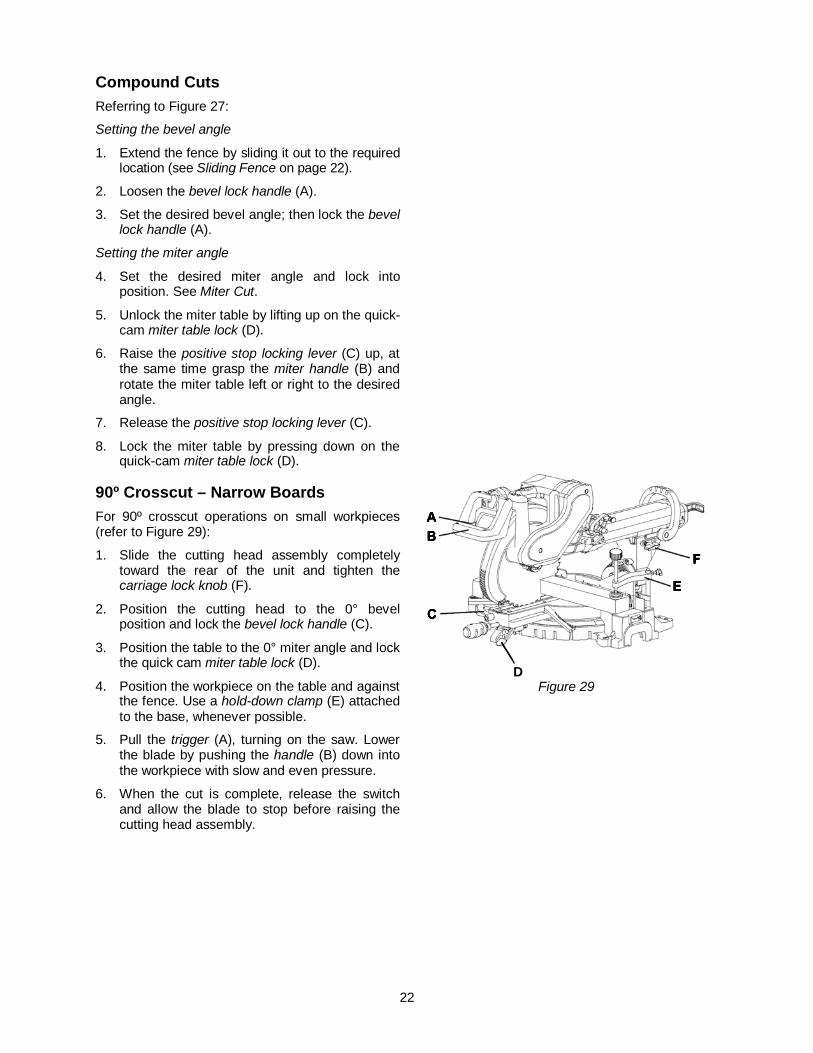
90º Crosscut – Narrow Boards For 90º crosscut operations on small workpieces (refer to Figure 29):
1. Slide the cutting head assembly completely toward the rear of the unit and tighten the carriage lock knob (F).
2. Position the cutting head to the 0° bevel position and lock the bevel lock handle (C).
3. Position the table to the 0° miter angle and lock the quick cam miter table lock (D).
4. Position the workpiece on the table and against the fence. Use a hold-down clamp (E) attached to the base, whenever possible.
5. Pull the trigger (A), turning on the saw. Lower the blade by pushing the handle (B) down into the workpiece with slow and even pressure.
6. When the cut is complete, release the switch and allow the blade to stop before raising the cutting head assembly.
Figure 29
D
23
Slide Cutting Wide Boards
Observe the following precautions: Never pull the cutting head assembly and
spinning blade toward you during the cut. Let the blade reach full speed before
cutting. Extending the fence by sliding it out to the
required location. Failure to comply may cause serious injury!
Use this operation to crosscut boards up to 12 inches wide.
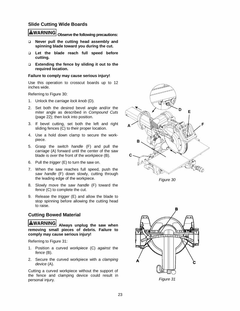
Referring to Figure 30:
1. Unlock the carriage lock knob (D).
2. Set both the desired bevel angle and/or the miter angle as described in Compound Cuts (page 22); then lock into position.
3. If bevel cutting, set both the left and right sliding fences (C) to their proper location.
4. Use a hold down clamp to secure the work-piece.
5. Grasp the switch handle (F) and pull the carriage (A) forward until the center of the saw blade is over the front of the workpiece (B).
6. Pull the trigger (E) to turn the saw on.
7. When the saw reaches full speed, push the saw handle (F) down slowly, cutting through the leading edge of the workpiece.
8. Slowly move the saw handle (F) toward the fence (C) to complete the cut.
9. Release the trigger (E) and allow the blade to stop spinning before allowing the cutting head to raise.
Cutting Bowed Material
Always unplug the saw when removing small pieces of debris. Failure to comply may cause serious injury!
Referring to Figure 31:
1. Position a curved workpiece (C) against the fence (B).
2. Secure the curved workpiece with a clamping device (A).
Cutting a curved workpiece without the support of the fence and clamping device could result in personal injury.
Figure 30
Figure 31
24
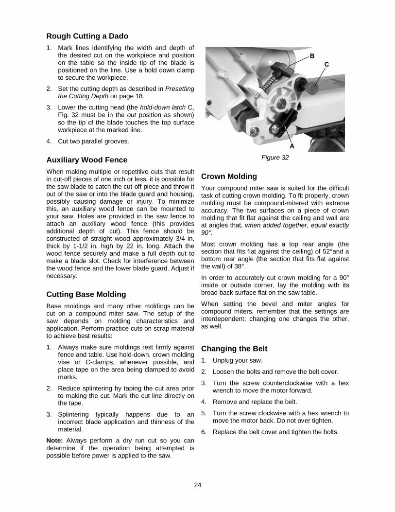
Rough Cutting a Dado 1. Mark lines identifying the width and depth of
the desired cut on the workpiece and position on the table so the inside tip of the blade is positioned on the line. Use a hold down clamp to secure the workpiece.
2. Set the cutting depth as described in Presetting the Cutting Depth on page 18.
3. Lower the cutting head (the hold-down latch C, Fig. 32 must be in the out position as shown) so the tip of the blade touches the top surface workpiece at the marked line.
4. Cut two parallel grooves.
Auxiliary Wood Fence When making multiple or repetitive cuts that result in cut-off pieces of one inch or less, it is possible for the saw blade to catch the cut-off piece and throw it out of the saw or into the blade guard and housing, possibly causing damage or injury. To minimize this, an auxiliary wood fence can be mounted to your saw. Holes are provided in the saw fence to attach an auxiliary wood fence (this provides additional depth of cut). This fence should be constructed of straight wood approximately 3/4 in. thick by 1-1/2 in. high by 22 in. long. Attach the wood fence securely and make a full depth cut to make a blade slot. Check for interference between the wood fence and the lower blade guard. Adjust if necessary.
Cutting Base Molding Base moldings and many other moldings can be cut on a compound miter saw. The setup of the saw depends on molding characteristics and application. Perform practice cuts on scrap material to achieve best results:
1. Always make sure moldings rest firmly against fence and table. Use hold-down, crown molding vise or C-clamps, whenever possible, and place tape on the area being clamped to avoid marks.
2. Reduce splintering by taping the cut area prior to making the cut. Mark the cut line directly on the tape.
3. Splintering typically happens due to an incorrect blade application and thinness of the material.
Note: Always perform a dry run cut so you can determine if the operation being attempted is possible before power is applied to the saw.
Figure 32
Crown Molding Your compound miter saw is suited for the difficult task of cutting crown molding. To fit properly, crown molding must be compound-mitered with extreme accuracy. The two surfaces on a piece of crown molding that fit flat against the ceiling and wall are at angles that, when added together, equal exactly 90°.
Most crown molding has a top rear angle (the section that fits flat against the ceiling) of 52°and a bottom rear angle (the section that fits flat against the wall) of 38°.
In order to accurately cut crown molding for a 90° inside or outside corner, lay the molding with its broad back surface flat on the saw table.
When setting the bevel and miter angles for compound miters, remember that the settings are interdependent; changing one changes the other, as well.
Changing the Belt 1. Unplug your saw.
2. Loosen the bolts and remove the belt cover.
3. Turn the screw counterclockwise with a hex wrench to move the motor forward.
4. Remove and replace the belt.
5. Turn the screw clockwise with a hex wrench to move the motor back. Do not over tighten.
6. Replace the belt cover and tighten the bolts.
25
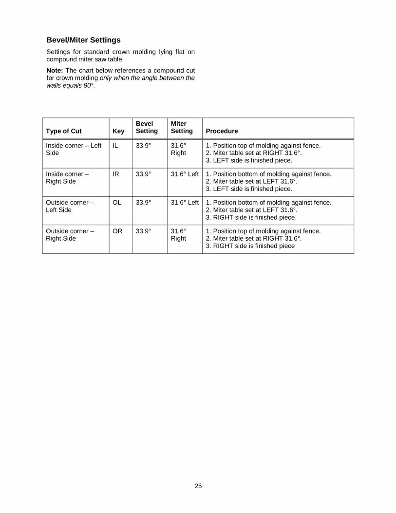
Bevel/Miter Settings Settings for standard crown molding lying flat on compound miter saw table.
Note: The chart below references a compound cut for crown molding only when the angle between the walls equals 90°.
Type of Cut Key Bevel Setting
Miter Setting Procedure
Inside corner – Left Side
IL 33.9° 31.6° Right
1. Position top of molding against fence. 2. Miter table set at RIGHT 31.6°. 3. LEFT side is finished piece.
Inside corner – Right Side
IR 33.9° 31.6° Left 1. Position bottom of molding against fence. 2. Miter table set at LEFT 31.6°. 3. LEFT side is finished piece.
Outside corner – Left Side
OL 33.9° 31.6° Left 1. Position bottom of molding against fence. 2. Miter table set at LEFT 31.6°. 3. RIGHT side is finished piece.
Outside corner – Right Side
OR 33.9° 31.6° Right
1. Position top of molding against fence. 2. Miter table set at RIGHT 31.6°. 3. RIGHT side is finished piece

26
Crown Molding Chart Compound miter saw miter and bevel angle settings, wall to crown molding angles
52/38º Crown Molding 45/45º Crown Molding 52/38º Crown Molding 45/45º Crown Molding Angle Between Walls
0Miter 0Setting
0Bevel 0Setting
0Miter 0Setting
0Bevel 0Setting
Angle Between Walls
0Miter 0Setting
0Bevel 0Setting
0Miter 0Setting
0Bevel 0Setting
67 42.93 41.08 46.89 36.13 124 18.13 21.71 20.61 19.39 68 42.39 40.79 46.35 35.89 125 17.77 21.34 20.21 19.06 69 41.85 40.50 45.81 35.64 126 17.42 20.96 19.81 18.72 70 41.32 40.20 45.28 35.40 127 17.06 20.59 19.42 18.39 71 40.79 39.90 44.75 35.15 128 16.71 20.21 19.03 18.06 72 40.28 39.61 44.22 34.89 129 16.37 19.83 18.64 17.72 73 39.76 39.30 43.70 34.64 130 16.02 19.45 18.25 17.39 74 39.25 39.00 43.18 35.38 131 15.67 19.07 17.86 17.05 75 38.74 38.69 42.66 34.12 132 15.33 18.69 17.48 16.71 76 38.24 38.39 42.15 33.86 133 14.99 18.31 17.09 16.38 77 37.74 38.08 41.64 33.60 134 14.66 17.93 16.71 16.04 78 37.24 37.76 41.13 33.33 135 14.30 17.55 16.32 15.70 79 36.75 37.45 40.62 33.07 136 13.97 17.17 15.94 15.36 80 36.27 37.13 40.12 32.80 137 13.63 16.79 15.56 15.02 81 35.79 36.81 39.62 32.53 138 13.30 16.40 15.19 14.62 82 35.31 36.49 39.13 32.25 139 12.96 16.02 14.81 14.34 83 34.83 36.17 38.63 31.98 140 12.63 15.64 14.43 14.00 84 34.36 35.85 38.14 31.70 141 12.30 15.25 14.06 13.65 85 33.90 35.52 37.66 31.42 142 11.97 14.87 13.68 13.31 86 33.43 35.19 37.17 31.34 143 11.64 14.48 13.31 12.97 87 32.97 34.86 36.69 30.86 144 11.31 14.09 12.94 12.62 88 32.52 34.53 36.21 30.57 145 10.99 13.71 12.57 12.29 89 32.07 34.20 35.74 30.29 146 10.66 13.32 12.20 11.93 90 31.62 33.86 35.26 30.00 147 10.34 12.93 11.83 11.59 91 31.17 33.53 34.79 29.71 148 10.01 12.54 11.46 11.24 92 30.73 33.19 34.33 29.42 149 9.69 12.16 11.09 10.89 93 30.30 32.86 33.86 29.13 150 9.37 11.77 10.73 10.55 94 29.86 32.51 33.40 28.83 151 9.05 11.38 10.36 10.20 95 29.43 32.17 32.94 28.54 152 8.73 10.99 10.00 9.85 96 29.00 31.82 32.48 28.24 153 8.41 10.60 9.63 9.50 97 28.58 31.48 32.02 27.94 154 8.09 10.21 9.27 9.15 98 28.16 31.13 31.58 27.64 155 7.77 9.82 8.91 8.80 99 27.74 30.78 31.13 27.34 156 7.46 9.43 8.55 8.45 100 27.32 30.43 30.68 27.03 157 7.14 9.04 8.19 8.10 101 26.91 30.08 30.24 26.73 158 6.82 8.65 7.83 7.75 102 26.50 29.73 29.80 26.42 159 6.51 8.26 7.47 7.40 103 26.09 29.38 29.36 26.12 160 6.20 7.86 7.11 7.05 104 25.69 29.02 28.92 25.81 161 5.88 7.47 6.75 6.70 105 25.29 28.67 28.48 25.50 162 5.57 7.08 6.39 6.35 106 24.89 28.31 28.05 25.19 163 5.26 6.69 6.03 6.00 107 24.49 27.96 27.62 24.87 164 4.95 6.30 5.68 5.65 108 24.10 27.59 27.19 24.56 165 4.63 5.90 5.32 5.30 109 23.71 27.23 26.77 24.24 166 4.32 5.51 4.96 4.94 110 23.32 26.87 26.34 23.93 167 4.01 5.12 4.61 4.59 111 22.93 26.51 25.92 23.61 168 3.70 4.72 4.25 4.24 112 22.55 26.15 25.50 23.29 169 3.39 4.33 3.90 3.89 113 22.17 25.78 25.08 22.97 170 3.08 3.94 3.54 3.53 114 21.79 25.42 24.66 22.66 171 2.77 3.54 3.19 3.10 115 21.42 25.05 24.25 22.33 172 2.47 3.15 2.83 2.83 116 21.04 24.68 23.84 22.01 173 2.15 2.75 2.48 2.47 117 20.67 24.31 23.43 21.68 174 1.85 2.36 2.12 2.12 118 20.30 23.94 23.02 21.36 175 1.54 1.97 1.77 1.77 119 19.93 23.57 22.61 21.03 176 1.23 1.58 1.41 1.41 120 19.57 23.20 22.21 20.70 177 0.92 1.18 1.06 1.06 121 19.20 22.83 21.80 20.38 178 0.62 0.79 0.71 0.71 122 18.84 22.46 21.40 20.05 179 0.31 0.39 0.35 0.35 123 18.48 22.09 21.00 19.72
27
Maintenance To avoid injury while
performing maintenance, always unplug the power cord before working on the saw. Failure to comply may cause serious injury!
Never use gasoline or any highly volatile solvents to clean the miter saw. Failure to comply may cause serious injury!
Use only replacement parts that are identical to the parts list at the end of this manual and reassemble exactly as the original assembly to avoid electrical shock. Failure to comply may cause serious injury!
Replacing Carbon Brushes Replace both carbon brushes when either has less than 1/4 in. length of carbon remaining, or if the spring or wire is damaged or burned.
To inspect or replace brushes:
1. Unplug the saw.
2. Remove the black plastic cap on the side of the motor
Remove the cap cautiously, because it is spring-loaded.
3. Pull out the brush and replace.
4. Reverse above steps to reassemble. Tighten the cap snugly, but do not over-tighten.
Replace the brush for the other side in the same manner described above.
Note: To reinstall the same brushes, first make sure the brushes go back in the way they came out. This will avoid a break-in period that reduces motor performance and increases wear.
Lower Blade Guard Do not use the saw without the lower blade guard. The lower blade guard is attached to the saw for your protection. Should the lower guard become damaged, do not use the saw until the damaged guard has been replaced. Develop a regular check to make sure the lower guard is working properly. Clean the lower guard of any dust or buildup with a damp cloth.
When cleaning the lower guard, unplug the saw from the power source receptacle to avoid unexpected startup.
Do not use solvents on the guard. They could make the plastic “cloudy” and brittle.
Saw Dust Periodically, saw dust will accumulate under the work table and base. This could cause difficulty in the movement of the worktable when setting up a miter cut. Frequently blow out or vacuum up the saw dust.
If blowing saw dust, wear proper eye protection to keep debris from entering eyes.
Lubrication All the motor bearings in this tool are lubricated with a sufficient amount of high grade lubricant for the life of the unit under normal operating conditions; therefore, no further lubrication is required.
Lubricate the following as necessary:
Chop pivot: Apply light machine oil.
Central pivot of plastic guard: Use light household oil (sewing machine oil) on metal-to-metal or metal-to-plastic guard contact areas as required for smooth, quiet operation. Avoid excessive oil, to which saw dust will cling.
28
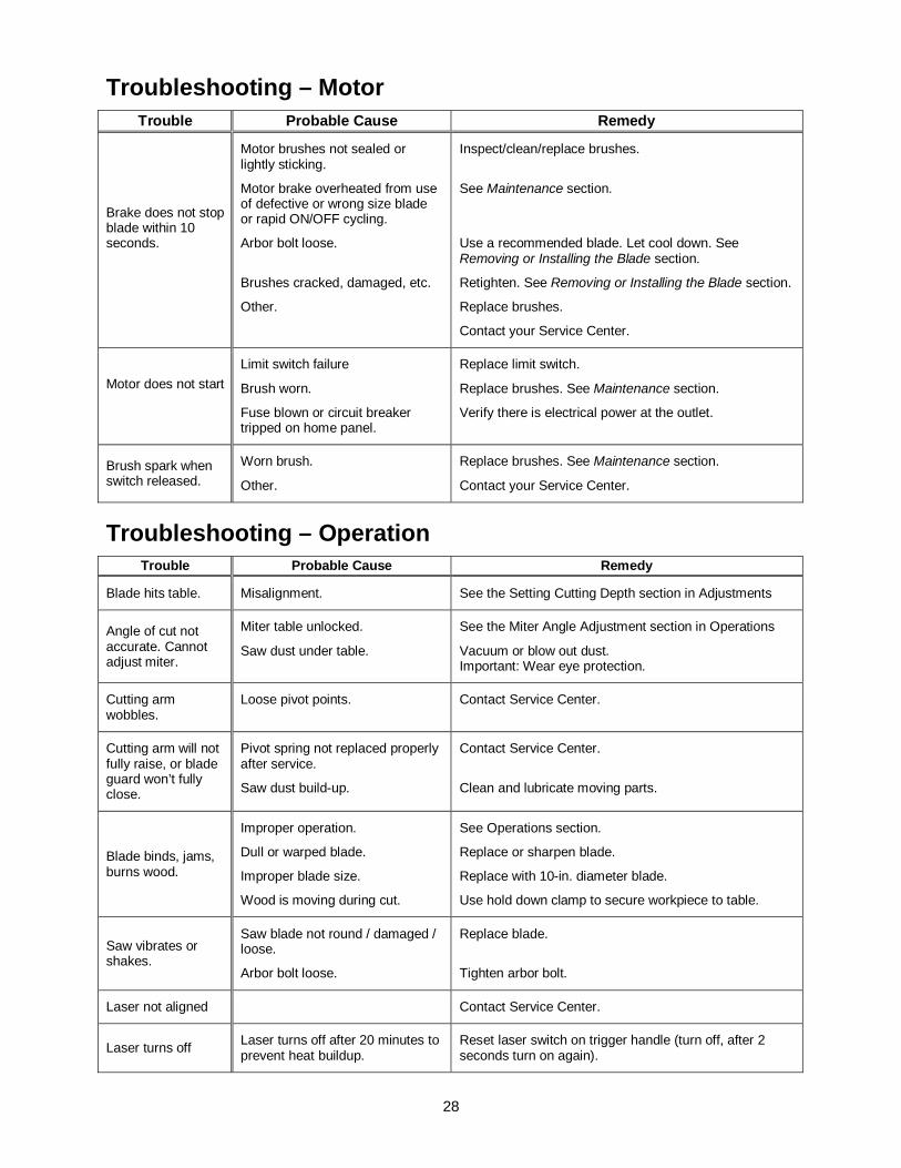
Troubleshooting – Motor Trouble Probable Cause Remedy
Brake does not stop blade within 10 seconds.
Motor brushes not sealed or lightly sticking.
Motor brake overheated from use of defective or wrong size blade or rapid ON/OFF cycling.
Arbor bolt loose.
Brushes cracked, damaged, etc.
Other.
Inspect/clean/replace brushes.
See Maintenance section.
Use a recommended blade. Let cool down. See Removing or Installing the Blade section.
Retighten. See Removing or Installing the Blade section.
Replace brushes.
Contact your Service Center.
Motor does not start
Limit switch failure
Brush worn.
Fuse blown or circuit breaker tripped on home panel.
Replace limit switch.
Replace brushes. See Maintenance section.
Verify there is electrical power at the outlet.
Brush spark when switch released.
Worn brush.
Other.
Replace brushes. See Maintenance section.
Contact your Service Center.
Troubleshooting – Operation Trouble Probable Cause Remedy
Blade hits table. Misalignment. See the Setting Cutting Depth section in Adjustments
Angle of cut not accurate. Cannot adjust miter.
Miter table unlocked.
Saw dust under table.
See the Miter Angle Adjustment section in Operations
Vacuum or blow out dust. Important: Wear eye protection.
Cutting arm wobbles.
Loose pivot points. Contact Service Center.
Cutting arm will not fully raise, or blade guard won’t fully close.
Pivot spring not replaced properly after service.
Saw dust build-up.
Contact Service Center.
Clean and lubricate moving parts.
Blade binds, jams, burns wood.
Improper operation.
Dull or warped blade.
Improper blade size.
Wood is moving during cut.
See Operations section.
Replace or sharpen blade.
Replace with 10-in. diameter blade.
Use hold down clamp to secure workpiece to table.
Saw vibrates or shakes.
Saw blade not round / damaged / loose.
Arbor bolt loose.
Replace blade.
Tighten arbor bolt.
Laser not aligned Contact Service Center.
Laser turns off Laser turns off after 20 minutes to prevent heat buildup.
Reset laser switch on trigger handle (turn off, after 2 seconds turn on again).

29
Parts Ordering Replacement Parts To order parts or reach our service department, call 1-800-274-6848 Monday through Friday (see our website for business hours, www.jettools.com). Having the Model Number and Serial Number of your machine available when you call will allow us to serve you quickly and accurately.
Parts List Note: Parts without part numbers are for reference only and cannot be purchased individually.
Index No. Part No. Description Size Qty 1 ............... JMS10SCMS-1 ........Shaft Sleeve .......................................................................................... 1 2 ............... JMS10SCMS-2 ........Knob ..................................................................................................... 1 3 ............... JMS10SCMS-3 ........Locator Pin ............................................................................................ 1 4 ............... JMS10SCMS-4 ........Label: Miter Quick Lock ......................................................................... 1 5 ............... JMS10SCMS-5 ........Compression Spring .............................................................................. 1 6 ............... JMS10SCMS-6 ........Cushion ................................................................................................. 2 7 ............... ................................Lock Screw ............................................................................................ 2 8 ............... JMS10SCMS-8 ........Nut ........................................................................................................ 1 9 ............... ................................Link ....................................................................................................... 1 10 ............. JMS10SCMS-10 ......Cord Clamp ........................................................................................... 1 11 ............. JMS10SCMS-11 ......Warning Label ....................................................................................... 1 12 ............. JMS10SCMS-12 ......Compression Spring .............................................................................. 1 13 ............. JMS10SCMS-13 ......Bumper ................................................................................................. 1 14 ............. JMS10SCMS-14 ......Knob ..................................................................................................... 1 15 ............. JMS10SCMS-15 ......Collar .................................................................................................... 1 16 ............. JMS10SCMS-16 ......Guard Spring ......................................................................................... 1 17 ............. JMS10SCMS-17 ......Center Bolt ............................................................................................ 1 18 ............. JMS10SCMS-18 ......Arbor Collar ........................................................................................... 2 19 ............. JMS10SCMS-19 ......Blade Wrench ........................................................................................ 1 20 ............. JMS12SCMS-27 ......Power Cord Clamp ................................................................................ 1 21 ............. JMS10SCMS-21 ......Pin......................................................................................................... 1 23 ............. ................................Ball Bearing ........................................................6003LLU .................... 1 24 ............. ................................Ball Bearing ........................................................607ZZ......................... 1 25 ............. ................................Ball Bearing ........................................................608ZZ......................... 1 26 ............. ................................Ball Bearing ........................................................6001ZZ....................... 1 27 ............. TS-1550031 .............Flat Washer ........................................................M5 .............................. 1 28 ............. TS-1550041 .............Flat Washer ........................................................M6 .............................. 2 29 ............. TS-155010 ...............Flat Washer ........................................................M16 ............................ 2 30 ............. TS-1550041 .............Flat Washer ........................................................M6 .............................. 2 31 ............. JMS10SCMS-31 ......Flat Washer ........................................................8x16x2.5 .................... 1 32 ............. JMS10SCMS-32 ......Flat Washer ........................................................1/4x7/16x1/16 ............. 4 33 ............. JMS10SCMS-33 ......Flat Washer ........................................................1/4x1/2x3/32 ............... 1 34 ............. JMS10SCMS-34 ......Flat Washer ........................................................1/4x5/8x3/32 ............... 1 35 ............. TS-0680041 .............Flat Washer ........................................................3/8 .............................. 1 36 ............. JMS10SCMS-36 ......External Tooth Lock Washer ...............................M5 .............................. 2 37 ............. JMS10SCMS-37 ......Wave Washer .....................................................WW-8 ......................... 2 38 ............. ................................Spring Pin...........................................................Ø5x16 ........................ 4 39 ............. ................................Spring Pin...........................................................Ø2.5x8 ....................... 2 40 ............. ................................C-Ring ................................................................A-12 ........................... 1 41 ............. JMS10SCMS-41 ......E-Clip .................................................................E-6 ............................. 1 42 ............. JMS10SCMS-42 ......O-Ring................................................................P10 ............................ 1 43 ............. JMS10SCMS-43 ......O-Ring................................................................P7 .............................. 1 45 ............. TS-1482051 .............Hex Cap Screw ..................................................M6x25 ........................ 2 46 ............. TS-1490081 .............Hex Cap Screw ..................................................M8x45 ........................ 1 47 ............. TS-1503041 .............Socket Head Cap Screw .....................................M6x16 ........................ 3

30
Parts List
Index No. Part No. Description Size Qty 48 ............. TS-1504031 .............Socket Head Cap Screw .....................................M8x16 ........................ 1 49 ............. TS-1504061 .............Socket Head Cap Screw .....................................M8x30 ........................ 2 50 ............. TS-1504121 .............Socket Head Cap Screw .....................................M8x60 ........................ 1 52 ............. TS-1524041 .............Socket Set Screw ...............................................M8x16 ........................ 1 53 ............. TS-1523031 .............Socket Set Screw ...............................................M6x10 ........................ 2 54 ............. JMS10SCMS-54 ......Arbor Bolt .............................................................................................. 1 55 ............. JMS10SCMS-55 ......Socket Head Cap Screw with Lock Washer ........M6x16 ........................ 1 56 ............. JMS10SCMS-56 ......Socket Head Cap Screw with Washer .................M8x25 ........................ 4 57 ............. JMS10SCMS-57 ......Hex Socket Truss Head Screw w/Lock Washer...M6x16 ........................ 4 58 ............. TS-1534051 .............Flat Head Screw .................................................M6x16 ........................ 1 59 ............. JMS10SCMS-59 ......Truss Head Screw ..............................................M5x8 .......................... 2 60 ............. JMS10SCMS-60 ......Truss Head Screw ..............................................M6x8 .......................... 4 61 ............. JMS10SCMS-61 ......Round Washer Head Screw................................M5x12 ........................ 1 62 ............. JMS10SCMS-62 ......Truss Head Round Neck Screw ..........................M6x18 ........................ 1 63 ............. JMS10SCMS-63 ......Truss Head Round Neck Screw ..........................M6x10 ........................ 2 64 ............. JMS10SCMS-64 ......Truss Head Round Neck Screw ..........................M6x14 ........................ 1 65 ............. JMS10SCMS-65 ......Pan Head Tapping Screw ...................................M3-24x10 ................... 2 66 ............. TS-2284082 .............Pan Head Screw ................................................M4x8 .......................... 7 67 ............. JMS10SCMS-72 ......Pan Head Screw ................................................M5x8 .......................... 2 68 ............. JMS10SCMS-68 ......Pan Head Tapping Screw ...................................M5-16x25 ................... 1 69 ............. JMS10SCMS-69 ......Pan Head Tapping Screw ...................................M4-18x25 ................... 5 70 ............. JMS10SCMS-70 ......Truss Head Tapping Screw ................................M4-16x12 ................... 1 71 ............. TS-1532052 .............Pan Head Screw ................................................M4x16 ........................ 4 72 ............. JMS10SCMS-72 ......Pan Head Screw ................................................M5x8 .......................... 3 73 ............. TS-1533062 .............Pan Head Screw ................................................M5x20 ........................ 1 74 ............. ................................Pan Head Screw ................................................M5x10 ........................ 4 75 ............. JMS10SCMS-75 ......Pan Head Screw ................................................M6x8 .......................... 2 76 ............. TS-1534052 .............Pan Head Screw ................................................M6x16 ........................ 3 77 ............. JMS10SCMS-77 ......Pan Head Round Neck Screw ............................M4x7.5 ....................... 2 78 ............. JMS10SCMS-78 ......Pan Head Round Neck Screw ............................M6x12 ........................ 1 79 ............. ................................Rivet ...................................................................Ø4x6.35 ..................... 5 81 ............. TS-1541011 .............Nylon Insert Lock Nut .........................................M5 .............................. 1 82 ............. TS-1541021 .............Nylon Insert Lock Nut .........................................M6 .............................. 4 83 ............. TS-1541031 .............Nylon Insert Lock Nut .........................................M8 .............................. 2 84 ............. TS-2342161 .............Nylon Insert Lock Nut .........................................M16 ............................ 1 85 ............. JMS10SCMS-85 ......Strain Relief ........................................................................................... 1 86 ............. JMS10SCMS-86 ......Cable Clamp ......................................................1/2" ............................ 2 88 ............. JMS10SCMS-88 ......Terminal ................................................................................................ 2 89 ............. TS-1541041 .............Nylon Insert Lock Nut .........................................M10 ............................ 1 90 ............. JMS10SCMS-90 ......Dust Bag ............................................................................................... 1 91 ............. TS-1540041 .............Hex Nut ..............................................................M6 .............................. 2 92 ............. JMS10SCMS-92 ......Washer...............................................................M8x23x1.5.................. 1 93 ............. JMS10SCMS-93 ......Label: Rotation ...................................................................................... 1 94 ............. ................................Pin......................................................................Ø5x16 ........................ 2 95 ............. JMS10SCMS-95 ......Knob ..................................................................................................... 2 96 ............. JMS10SCMS-96 ......Stop Screw ............................................................................................ 1 97 ............. JMS10SCMS-97 ......Bevel Lock Handle ................................................................................. 1 98 ............. JMS10SCMS-98 ......Pointer................................................................................................... 1 99 ............. JMS10SCMS-99 ......Disc ....................................................................................................... 1 100 ........... JMS10SCMS-100 ....Anchor Plate .......................................................................................... 1 101 ........... JMS10SCMS-101 ....Pulley .................................................................................................... 1 102 ........... JMS10SCMS-102 ....Power Cord ........................................................................................... 1 103 ........... JMS10SCMS-103 ....Warning Label: Avoid Exposure ............................................................. 1 104 ........... JMS10SCMS-104 ....Bushing ................................................................................................. 1 105 ........... JMS10SCMS-105 ....Locking Rod .......................................................................................... 1

31
Parts List
Index No. Part No. Description Size Qty 106 ........... ................................Slide Bar, Right ..................................................................................... 1 107 ........... ................................Slide Bar, Left ........................................................................................ 1 108 ........... JMS10SCMS-108 ....Pivot Shaft ............................................................................................. 1 109 ........... JMS10SCMS-109 ....Label: Bevel Lock .................................................................................. 1 110 ........... JMS10SCMS-110 ....Table Insert, Right ................................................................................. 1 111 ........... JMS10SCMS-111 ....Table Insert, Left ................................................................................... 1 112 ........... ................................Collar .................................................................................................... 1 113 ........... ................................Shaft ..................................................................................................... 1 114 ........... JMS10SCMS-114 ....Set Nut .................................................................................................. 1 115 ........... JMS10SCMS-115 ....Screw Stop ............................................................................................ 1 116 ........... JMS10SCMS-116 ....Lock Knob ............................................................................................. 1 117 ........... JMS10SCMS-117 ....Lock Knob ............................................................................................. 1 118 ........... JMS10SCMS-118 ....Anchor Plate .......................................................................................... 1 119 ........... JMS10SCMS-119 ....Compression Spring .............................................................................. 1 120 ........... JMS10SCMS-120 ....Pin......................................................................Ø4x22 ........................ 1 121 ........... JMS10SCMS-121 ....Compression Spring .............................................................................. 1 122 ........... TS-1523051 .............Socket Set Screw ...............................................M6x16 ........................ 2 124 ........... JMS10SCMS-124 ....SHCS with Lock Washer & Flat Washer..............M5x12 ........................ 4 125 ........... ................................Helix Gear ............................................................................................. 1 126 ........... JMS10SCMS-126 ....Base ...................................................................................................... 1 127 ........... JMS10SCMS-127 ....Fence .................................................................................................... 1 128 ........... JMS10SCMS-128 ....Fence Extension, Left ............................................................................ 1 129 ........... JMS10SCMS-129 ....Fence Extension, Right .......................................................................... 1 130 ........... JMS10SCMS-130 ....Slide Plate ............................................................................................. 3 131 ........... ................................Lock Handle .......................................................................................... 1 132 ........... JMS10SCMS-132 ....Table ..................................................................................................... 1 133 ........... JMS10SCMS-133 ....Pointer, Left ........................................................................................... 1 134 ........... JMS10SCMS-134 ....Pointer, Right......................................................................................... 1 136 ........... JMS10SCMS-136 ....Handle................................................................................................... 1 137 ........... ................................Pivot Support ......................................................................................... 1 138 ........... ................................Rear Slide Bar Seat ............................................................................... 1 139 ........... ................................Arbor ..................................................................................................... 1 140 ........... ................................Bracing Plate ......................................................................................... 1 141 ........... JMS10SCMS-141 ....Guard Plate ........................................................................................... 1 142 ........... ................................Blade Guard .......................................................................................... 1 143 ........... JMS10SCMS-143 ....Gear Box Cover ..................................................................................... 1 144 ........... JMS10SCMS-144 ....Lever ..................................................................................................... 1 145 ........... JMS10SCMS-145 ....Saw Arm ............................................................................................... 1 146 ........... JMS10SCMS-146 ....Hex Cap Screw (LH Threads) .............................M6x16 ........................ 1 147 ........... JMS10SCMS-147 ....SHCS with Lock Washer & Flat Washer..............M5x40 ........................ 1 148 ........... JMS10SCMS-148 ....Upper Handle Segment ......................................................................... 1 149 ........... JMS10SCMS-149 ....Lower Handle Segment ......................................................................... 1 150 ........... JMS10SCMS-150 ....Collar .................................................................................................... 1 151 ........... JMS10SCMS-151 ....Plate ...................................................................................................... 2 152 ........... ................................Gear Shaft ............................................................................................. 1 153 ........... JMS10SCMS-153 ....Torsion Spring ....................................................................................... 1 154 ........... ................................Bearing Protector................................................................................... 1 155 ........... JMS10SCMS-155 ....Washer.................................................................................................. 4 156 ........... JMS10SCMS-156 ....V-Ribbed Belt .....................................................195J8 ......................... 1 157 ........... JMS10SCMS-157 ....Pivot Shaft ............................................................................................. 1 158 ........... JMS10SCMS-158 ....Locating Bar .......................................................................................... 1 159 ........... JMS10SCMS-159 ....Linear Motion Bearing.........................................LM30LLU ................... 1 160 ........... JMS10SCMS-160 ....Blade Guard Assembly .......................................................................... 1 161 ........... JMS10SCMS-161 ....Locking Handle Assembly ...................................................................... 1 162 ........... JMS10SCMS-162 ....Slotted Set Screw ...............................................M6x8 .......................... 4 163 ........... JMS10SCMS-163 ....Gasket................................................................................................... 1

32
Parts List
Index No. Part No. Description Size Qty 164 ........... JMS10SCMS-164 ....Compression Spring .............................................................................. 1 165 ........... JMS10SCMS-165 ....Truss Head Screw ..............................................M3x12 ........................ 1 166 ........... ................................Key.....................................................................4x4x8 ......................... 1 167 ........... JMS10SCMS-167 ....Gear Shaft Assembly ............................................................................. 1 168 ........... JMS10SCMS-168 ....Arbor Assembly ..................................................................................... 1 169 ........... JMS10SCMS-169 ....Base Rear Extension ............................................................................. 1 170 ........... JMS10SCMS-170 ....Rocker Switch ....................................................................................... 1 171 ........... JMS10SCMS-171 ....Warning Label ....................................................................................... 1 172 ........... JMS10SCMS-172 ....Label: Do Not Remove .......................................................................... 2 173 ........... JMS10SCMS-173 ....Insulator ................................................................................................ 1 174 ........... JMS10SCMS-174 ....Rivet ...................................................................................................... 2 175 ........... JMS10SCMS-175 ....Locking Knob......................................................................................... 1 176 ........... JMS10SCMS-176 ....Upper Handle ........................................................................................ 1 177 ........... JMS10SCMS-177 ....Lower Handle ........................................................................................ 1 178 ........... JMS10SCMS-178 ....Laser Housing ....................................................................................... 1 179 ........... JMS10SCMS-179 ....Slide Bar Guard ..................................................................................... 1 180 ........... JMS10SCMS-180 ....Pulley Cover .......................................................................................... 1 181 ........... JMS10SCMS-181 ....Locking Handle Assembly ...................................................................... 1 182 ........... JMS10SCMS-182 ....Release Lever ....................................................................................... 1 183 ........... JMS10SCMS-183 ....Clear Panel ........................................................................................... 1 184 ........... JMS10SCMS-184 ....Locking Handle Assembly ...................................................................... 2 185 ........... ................................Lock Handle .......................................................................................... 2 186 ........... JMS10SCMS-186 ....Guard Plate ........................................................................................... 2 187 ........... JMS10SCMS-187 ....Green Laser Controller Assembly .......................................................... 1 188 ........... JMS10SCMS-188 ....Green Laser .......................................................................................... 1 190 ........... JMS10SCMS-190 ....Slide Bar Assembly ............................................................................... 1 191 ........... JMS10SCMS-191 ....Motor ..................................................................................................... 1 ..............JMS10SCMS-191MB ...Motor Brush (not shown)........................................................................ 2 ............JMS10SCMS-191MBC ..Motor Brush Cover (not shown) ............................................................. 2 192 ........... JMS10SCMS-192 ....Saw Blade ..........................................................10”x40Tx5/8” Arbor ..... 1 193 ........... JMS10SCMS-193 ....Guard .................................................................................................... 1 194 ........... JMS10SCMS-194 ....Clamp Hold Down Assembly.................................................................. 1 195 ........... JMS10SCMS-195 ....Lead Wire .............................................................................................. 1 196 ........... JMS10SCMS-196 ....Laser Housing Bracket .......................................................................... 1 198 ........... JMS10SCMS-198 ....Label: Laser Caution.............................................................................. 1 199 ........... JMS10SCMS-199 ....JET Label for Pulley Cover .................................................................... 1 200 ........... JMS10SCMS-200 ....Label: Laser On/Off ............................................................................... 1 201 ........... JMS10SCMS-201 ....JET Label for Slide Bar Guard ............................................................... 1 202 ........... JMS10SCMS-202 ....JET Label .............................................................................................. 1 203 ........... JMS10SCMS-203 ....ID Label ................................................................................................. 1 204 ........... JMS10SCMS-204 ....JET Label for Handle ............................................................................. 1 205 ........... JMS10SCMS-205 ....Bevel Angle Scale ................................................................................. 1 206 ........... TS-0680041 .............Flat Washer ........................................................3/8 .............................. 1 207 ........... JMS10SCMS-207 ....Special Bolt ........................................................................................... 1 208 ........... JMS10SCMS-208 ....Trigger Switch ....................................................................................... 1 209 ........... JMS10SCMS-209 ....Miter Angle Scale .................................................................................. 1 210 ........... JMS10SCMS-210 ....Cable Clamp ......................................................1/8”............................. 1 211 ........... JBTS10MJS-70 ........Pan Head Tapping Screw ...................................M3-24x6 ..................... 1 212 ........... JMS10SCMS-212 ....O-Ring................................................................30x3.5 ........................ 2 213 ........... TS-1502051 .............Socket Head Cap Screw .....................................M5x20 ........................ 4 214 ........... JMS10SCMS-214 ....Cover Plate ........................................................................................... 1 215 ........... JMS10SCMS-215 ....Cover Plate ........................................................................................... 1 216 ........... JMS10SCMS-216 ....Slide/Bevel Arm ..................................................................................... 1 217 ........... JMS10SCMS-217 ....Collar .................................................................................................... 1 218 ........... JMS10SCMS-218 ....Linear Motion Bearing.........................................LM30SUU................... 1
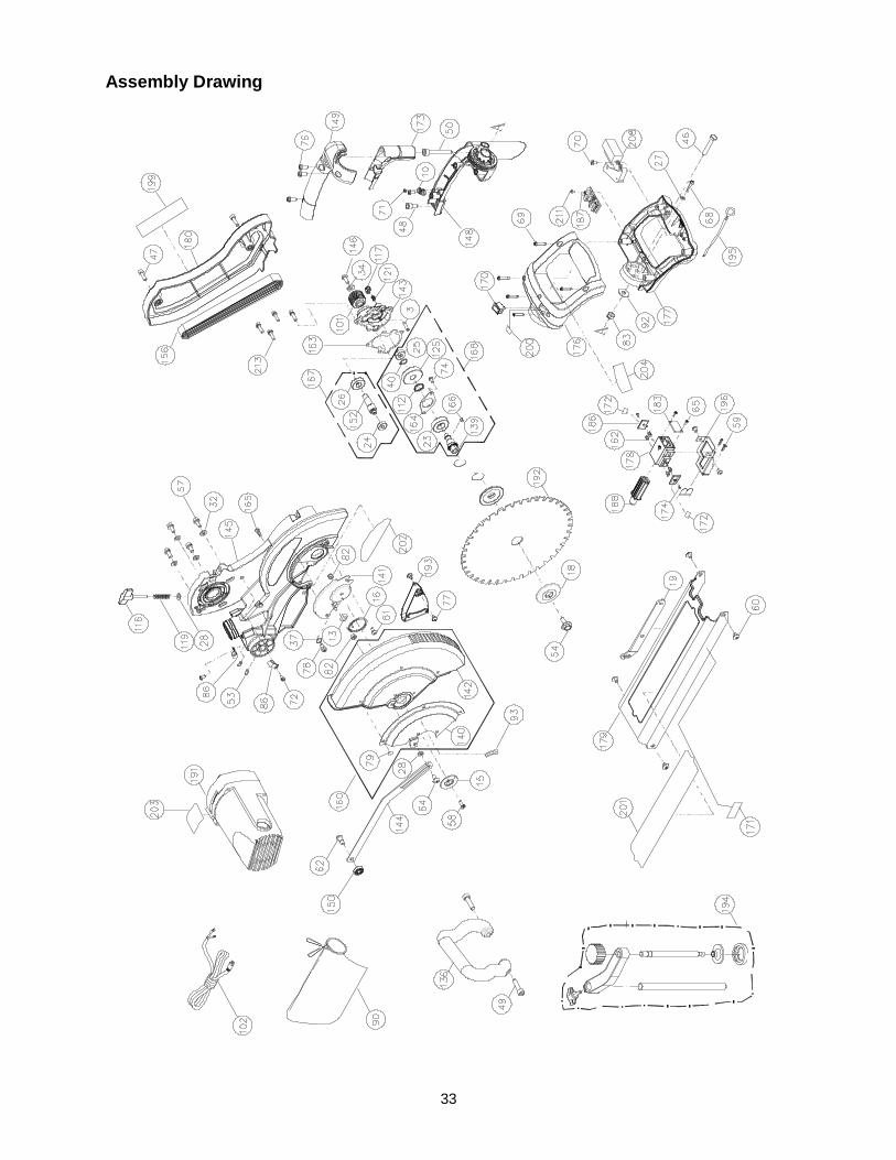
33
Assembly Drawing
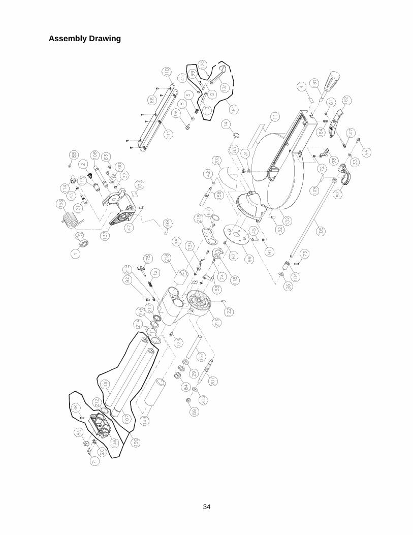
34
Assembly Drawing
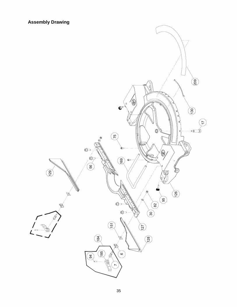
35
Assembly Drawing
95
130
209
17
184
7169
75
3082
128
126
127151
56
6185
94
129
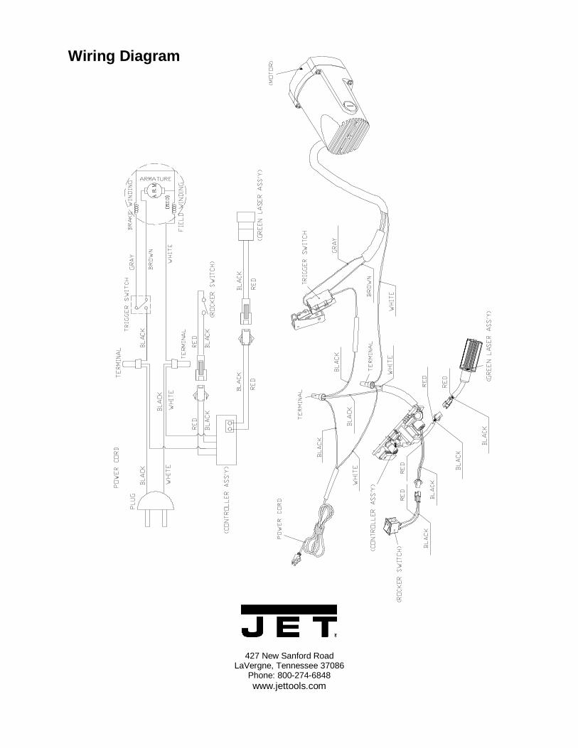
36
Wiring Diagram
427 New Sanford Road LaVergne, Tennessee 37086
Phone: 800-274-6848 www.jettools.com