Embed Size (px)
Citation preview
Operating Instructionsfor the WABCO Diagnostic Controller with Program Card ABS-D KWP446 300 739 0

Operating Instructions
for the WABCO Diagnostic Controller446 300 320 0with Program Card ABS-D KWP446 300 739 0
Edition: December 2000
© Copyright WABCO 2000
Vehicle Control SystemsAn American Standard Company
The right of amendment is reserved

2
TABLE OF CONTENTSPage
1. DIAGNOSTIC CONTROLLER SET 31.1 General 41.2 Operation of the Diagnostic Controller 4
2. CONNECTING THE DIAGNOSTIC CONTROLLER 53. PROGRAM STRUCTURE 6
3.1 Menu Selection 63.2 Functional Scope of Menu Items 7
3.2.1 Diagnosis 73.2.1.1 Error Memory 73.2.1.2 Component Actuate 83.2.1.3 Testing and Measuring Values 103.2.1.4 Control Unit Data 103.2.2 Commissioning 113.2.2.1 Functional Testing 113.2.2.2 Order in Which Components Are Tested 113.2.2.3 Printing the Test Log 113.2.3 Multimeter 123.2.4 Options 133.2.4.1 Help Texts 133.2.4.2 Version 133.2.4.3 ECUs Which Can Be Tested 133.2.4.4 Change Address 133.2.5 Special Functions 13
4. Functional Defects 145. Log Examples 18
5.1 Commissioning 185.2 Parameter Settings 195.3 Error Memory 20
List of abbreviations used:ABS Anti-Lock Braking SystemASR Anti-Spin Regulation (Drive-Slip Contol)ECU Electronic Control UnitHA rear axleli leftre rightVA front axleVR front right

3
1. DIAGNOSTIC CONTROLLER SET 446 300 331 0
Contents of Diagnostic Controller Set:1. Diagnostic Controller 446 300 320 02. Carrying Case 446 300 022 2
Accessories:3. Program Card 446 300 739 04. Connector Cable 446 300 404 05. Multimeter Cable, black 894 604 301 2
Multimeter Cable, red 894 604 302 26. Keyboard 446 300 328 0
1
2
3
4
5
6

4
1.1 General
The Diagnostic Controller, referred to as the“Controller“ below, has been developed forthe purpose of testing Electronic ControlUnits (ECUs). It can be used to read out datafrom the ECU, and to write into them. In ad-dition, commands can be sent to the ECUwhich are used to actuate individual compo-nents on the vehicle.
In order to be able to communicate with anECU, a special Diagnostic Program is re-quired. This is stored on a Program Card. Ifan attempt is made to connect and operatean ECU with a Diagnostic Program which isnot intended for that ECU, the Controller willreact by showing the following message:
*** Unknown control unit ***Diagnosis not possiblewith this program card !
CONTINUE
The Program Card is an electronic storagemedium whose address lines start at thegold-plated contact points. Any damage toany of these points or to a lead (scratch) cancause the card to fail altogether.
Insert card:Make sure the contact side faces upwards.
1.2 Operation of the DiagnosticController
The Controller is operated by means of threepush-buttons on the front panel. Their allo-cation is shown via the instructions appear-
ing on the display directly above therespective push-buttons.
1 Diagnosis 4 Options2 System check 5 Special functions3 MultimeterSelect function! EXIT START
display instruction(function) push-buttons
Here are some examples for different push-button functions:
push-button functionSTART The menu item selected is
initiated.EXIT The display will return to the previ-
ous menu or program item.
Selecting a menu item from themain menu. Every time the button ispressed, the next menu item isaddressed. The selected menu itemwill flash.
CONTINUEThe menu item selected is trig-gered, i. e. activated.
ABORT You have the option to abort thefunction in the event of an error.
END Ending the function you havebeen working on, i. e. settingparameters.
CHANGE Changing the parametersappearing in the display.

5
1.2.2 Operating the External Key-board 446 300 328 0
The use of an external keyboard is recom-mended as it makes it very easy to operatethe Controller. Only the push-buttons marked are reservedfor special functions.
The keys can be usedinstead oft he three push-buttons on the Di-agnostic Controller.
Exception: if it is necessary to enter figuresduring the program, this function does notapply.
Using the ten-key block it is possible either to enter numerical data(for example ISO addresses) or to selectnumbered items from a menu.
Using the key, the menu itemindicated is executed. The key has the samefunction as the controller key CONTINUE.
Using you can revert to the previousmain menu displayed.
Using , when there is a series of datadisplayed (eg., parameter, function test,calibration data), you can revert to theprevious display.
2. CONNECTING THE DIAGNOSTIC CONTROLLER
The Diagnostic Controller is connected tothe vehicle with a special cable:
SUB DB9 Socket
Pin 1 +24 volts (red)Pin 2 ground (brown)Pin 8 K-line (yellow)
Connect the plug to the vehicle and the SUBDB9 socket to the Diagnostic Controller.This not only establishes the diagnosticconnection but also provides the voltagesupply. Black bars will appear in the display.
Now you push the program card into the slotprovided. Make sure that the contacts on thecard face upwards.
You will now see something like this in thedisplay:
DIAGNOSTIC PROGRAM ABS-D KWPVersion 1.00 (English)
START
If this is not the case, please refer to Chapter4 on Functional Defects “DIAGNOSIS“. Thefirst display shows the system tested and theversion (in this case 1.00).
0
ENTER.
0 1 9to
ENTER
C
*
6
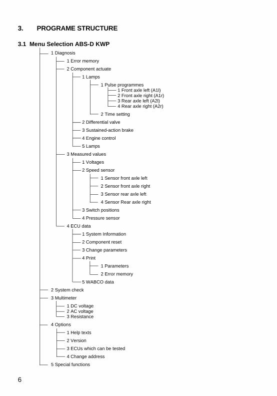
3. PROGRAME STRUCTURE
3.1 Menu Selection ABS-D KWP1 Diagnosis
1 Error memory
2 Component actuate
1 Lamps
1 Pulse programmes1 Front axle left (A1l)2 Front axle right (A1r)3 Rear axle left (A2l)4 Rear axle right (A2r)
2 Time setting
2 Differential valve
3 Sustained-action brake
4 Engine control
5 Lamps
3 Measured values
1 Voltages
2 Speed sensor
1 Sensor front axle left
2 Sensor front axle right
3 Sensor rear axle left
4 Sensor Rear axle right
3 Switch positions
4 Pressure sensor
4 ECU data
1 System Information
2 Component reset
3 Change parameters
4 Print
1 Parameters
2 Error memory
5 WABCO data
2 System check
3 Multimeter
1 DC voltage 2 AC voltage3 Resistance
4 Options
1 Help texts
2 Version
3 ECUs which can be tested
4 Change address
5 Special functions
7
3.2 Functional Scope of Menu Items
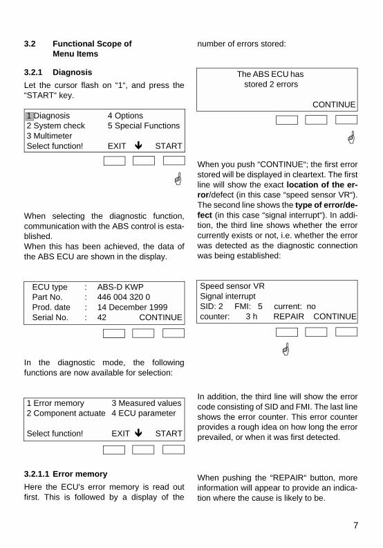
3.2.1 DiagnosisLet the cursor flash on “1“, and press the“START“ key.
1 Diagnosis 4 Options2 System check 5 Special Functions3 MultimeterSelect function! EXIT START
When selecting the diagnostic function,communication with the ABS control is esta-blished. When this has been achieved, the data ofthe ABS ECU are shown in the display.
ECU type : ABS-D KWPPart No. : 446 004 320 0Prod. date : 14 December 1999Serial No. : 42 CONTINUE
In the diagnostic mode, the followingfunctions are now available for selection:
1 Error memory 3 Measured values2 Component actuate 4 ECU parameter
Select function! EXIT START
3.2.1.1 Error memoryHere the ECU's error memory is read outfirst. This is followed by a display of the
number of errors stored:
The ABS ECU has stored 2 errors
CONTINUE
When you push “CONTINUE“; the first errorstored will be displayed in cleartext. The firstline will show the exact location of the er-ror/defect (in this case “speed sensor VR“).The second line shows the type of error/de-fect (in this case “signal interrupt“). In addi-tion, the third line shows whether the errorcurrently exists or not, i.e. whether the errorwas detected as the diagnostic connectionwas being established:
Speed sensor VRSignal interruptSID: 2 FMI: 5 current: no counter: 3 h REPAIR CONTINUE
In addition, the third line will show the errorcode consisting of SID and FMI. The last lineshows the error counter. This error counterprovides a rough idea on how long the errorprevailed, or when it was first detected.
When pushing the “REPAIR“ button, moreinformation will appear to provide an indica-tion where the cause is likely to be.

8
T1 T2 T3 T1 T2T3 T3
Bremsdruck
Pedalbetätigung
Modulatoransteuerung
Heben
Senken
Halten
Min
Max
Min
Max
T1: 3 ... 500 msT2: 4sT3: 2s
control pressure
pedal actuation
modulator actuate
max
min
max
min
raise
hold
lower
Check the wiring,replace sensor as required.
CONTINUE
When pushing the “CONTINUE“ button, thenext error will be displayed.
When all errors have been displayed, the er-ror memory of the ECU can be deleted.
Delete error memory of the ABS ECU ?
YES NO
If the answer to this question is “NO“, the er-ror search is aborted. If it is “YES“, the errormemory of the ECU is erased and you willbriefly leave the diagnostic mode (to allowthe electronics to again detect any errorsand to store them in the error memory).
This is followed by the error memory beingread again, and the findings displayed. Ifother errors are stored, the procedure isagain as described above.
3.2.1.2 Components Actuate“Actuate“ can be used to actuate specificcomponents of ABS to verify that they arefully operational. If a component is selectedwhich, according to the parameters, has notbeen installed on the vehicle, a correspond-ing message will be displayed.
1 Modulators 4 Engine control2 Differential valve 5 Lamps3 sustained-action brakeSelect function! BACK CONTINUE
3.2.1.2.1 ModulatorsFor testing the modulators, a pulse programis available which can be executed both ona roller dynamometer or by using pressuregauges.
Sequence of the pulse program for the mod-ulators:

9
Time T1 determines the level of control pres-sure for the time T2. Time T1 can be setwithin a range of 3 to 500 ms. For this pur-pose, menu item 1.2.1.2 Time Setting isused. A value of 50 ms has been preset.
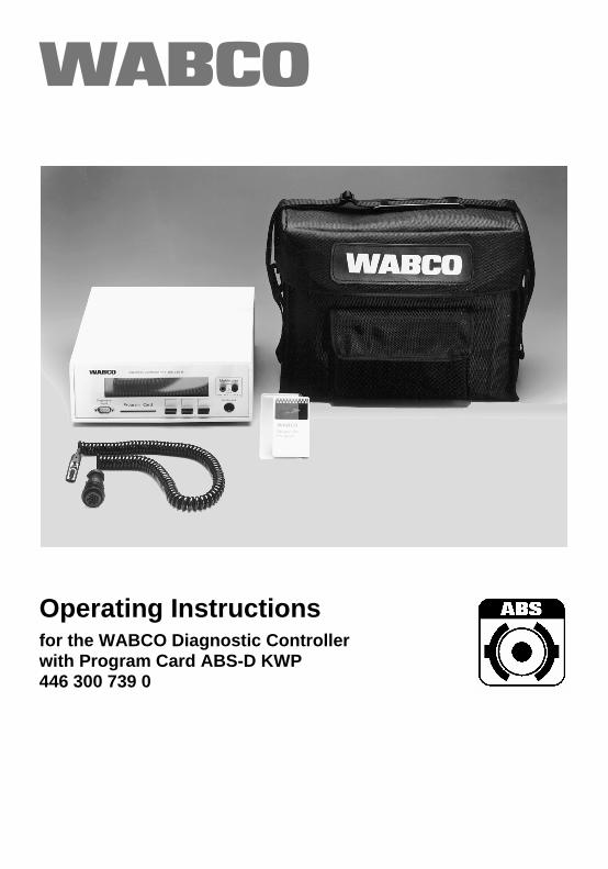
3.2.1.2.2 Differential ValveA pulse program is also available for the dif-ferential valve. This program may NOT beexecuted on the roller dynamometer as thevehicle would ’jump’ from the roller when itsrear axle is braked.
The course of the control pressure on therear wheels must be measured using pres-sure gauges.
3.2.1.2.3 Sustained-Action BrakeThis menu item can be used to check the de-activation of the sustained-action brake.This test can be done on the roller dy-namometer. However, the vehicle MUST besecured to make sure it cannot roll away.The sustained-action brake can be switchedoff while the button is being pushed. This de-activation acts on the deactivation relay forthe sustained-action brake and on the sus-tained-action brake capable of CAN.
3.2.1.2.4 Engine ControlIf the vehicle has an engine interface, theengine speed can be reduced to its idlinglevel for approx. 5 sec. If the parameter for atowing torque has been set, the enginespeed is then increased for approx. 5 sec. to10% of full power.
Bremsdruck
Modulatoransteuerung
Diff.-Ventil
Min
Max
Heben
Halten
Senken
An
Aus
T1 T2 T3T2 T2T1: 3 ... 500 msT2: 2sT3: 150 ms
control pressure
modulator actuate
Differential valve
max
min
on
off
raise
hold
lower
Again the control pressure for time T2 is de-pendent on time T1. This time can be set asdescribed for Menu Item 1.2.1.2 Time Set-ting. A value of 50 ms has been preset.

10
3.2.1.2.5 LampsAll lamps which have been installed can beswitched on and off manually, one by one.
3.2.1.3 Testing and Measuring ValuesThis part of the program can be used to dis-play switch positions and measuring values.In the event of a component supplying aninvalid signal, the program will show threedashes ‘---‘ instead of the (wrong) measur-ing value. If a component is selected which,according to the ECU’s parameters, has notbeen installed on the vehicle, a correspond-ing message will appear. No measuring val-ue will then be displayed.
3.2.1.3.1 VoltagesThe supply voltages Uvent and Ues are dis-played. In addition to the current voltages,the reference values will also be shown.
3.2.1.3.2 Speed SensorsThe minimum and maximum output voltageamplitudes of the speed sensors, the ratio ofmaximum/minimum amplitude and thewheel speed are shown. The wheel speed isshown from speeds in excess of 1.3 k.p.h.
3.2.1.3.3 Switch PositionsThe positions of the following switches aredisplayed:
ABS function (normal/off-road)ASR function (normal/off-road or
deactivated)Brake signal (activated/deactiva-
ted)
The display of the switch status of the ASRswitch/button depends on the parametersset. If no ASR function has been implement-ed, three dashes are shown instead of a sta-tus message.
3.2.1.3.4 Pressure SensorsIf the parameter has been set for a pressuresensor, the sensor’s output voltage in [mV]and the brake light status (activated/deacti-vated) will be displayed.
3.2.1.4 Control Unit DataThis menu item has been provided for show-ing and adjusting manufacturing data andthe system configuration.
1 System Info 4 Print2 Components reset 5 Display WABCO data 3 Change parameterSelect function! EXIT START
3.2.1.4.1 System InformationTwo consecutive illustrations show whichcomponents have been installed on the ve-hicle.
3.2.1.4.2 Components ResetTo allow the ECU to automatically recognizethe components installed on the vehicle, thisfunction can be used to trigger the automaticlearning process. Afterwards, the ignitionmust be switched off and then on again.
3.2.1.4.3 Change ParametersThe parameters for the vehicle are dis-played. After entering the PIN, these param-eters can be changed. If you press ‘ * ’ on theexternal keyboard, you will return to the pre-vious parameter.
When the last parameter has been reached,or by pushing the ’END’ button, the new val-ues can be stored in the ABS control unit.

11
3.2.1.4.4 PrintingThis menu item can be used to either printthe parameters which have been set, or thecontents of the error memory.
3.2.1.4.5 WABCO DataThe ECU’s manufacturing data are dis-played.
3.2.2 Commissioning’Commissioning’ is used to perform a fullsystem test of ABS (e.g. after its initial instal-lation or after major repairs).
Commissioning is divided into three sec-tions:
Function testing Error output Print log
Please note:If the voltage supply for the Controller is bro-ken, all data previously stored are deleted.For this reason the diagnostic connectionshould never be severed if a printed log is re-quired.
All steps within the test procedure can be re-peated until they have been successfullycompleted.
In some cases, the Controller may decideautomatically whether a step within the testprocedure has been performed properly(e.g. actuation of a button). Otherwise theoperator will be asked to assess the proce-dure (e.g. after pulse programs).
3.2.2.1 Functional TestingThe functional test can only be performed ifno errors have been stored. The vehicle maybe moved only if the program expressly asksthe operator to do so.
3.2.2.2 Order in Which ComponentsAre Tested
error memory operating voltages lamps
switches pressure sensor modulators and speed sensors by
wheels differential valve sustained-action brakes engine interface
3.2.2.3 Print System CheckAt the end of the test the results can beprinted.
As mentioned above, the Controller has tobe permanently connected to the voltagesupply. Any interruption will destroy all datastored.
Connection with the printer is establishedvia the 25-pin socket on the rear and aserial printer cable. The cable must have aDB 25-plug (not socket !) at both ends.

12
The program works with EPSON FX-compa-tible printers with a serial interface (RS 232).The transmission parameters of the printermust be set to the configuration shown be-low:Speed: 1200 baudData bits: 8Stop bit: 1Parity bit: X ON / X OFF
3.2.3 Multimeter
1 DC voltage 3 Resistance2 AC voltage
Select function! EXIT START
The integrated multimeter function permitselectric measurements on the vehicle. Onlythe desired measuring function (direct volta-ge, alternating voltage or resistance) needsto be selected. The measuring range is au-tomatically set by the unit.
Application:Direct voltage: supply voltage on the
vehicleAlternating voltage: sensor voltageResistance: valves, relays,
sensors, wiring
PLEASE NOTE: The measuring instru-ment is designed only for measurings withinthe vehicle-specific-range (low voltage). Itmust not be used beyond the above-men-tioned measuring range.
Range Display resolution Accuracy of measuring range at 20°C
DC voltage 2.0 volt20.0 volt50.0 volt
0.1 volt0.1 volt0.1 volt
± 0.2 %± 0.2 %± 0.2 %
± 0.0 volt± 0.1 volt± 0.1 volt
AC voltage 2.0 volt35.0 volt
0.01 volt0.10 volt
± 0.6 %± 0.6 %
± 0.02 volt± 0.40 volt
Resistance 20.0 Ω200.0 Ω
2.0 kΩ 20.0 kΩ 95.0 kΩ
0.1 Ω 0.1 Ω 1.0 Ω 10.0 Ω 100.0 Ω
± 0.3 %± 0.2 %± 0.2 %± 0.1 %± 0.2 %
± 0.1 Ω± 0.1 Ω± 1.0 Ω± 10.0 Ω± 100.0 Ω
13
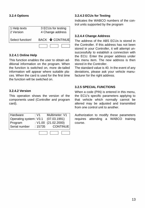
3.2.4 Options
1 Help texts 3 ECUs for testing2 Version 4 Change address
Select function! BACK CONTINUE
3.2.4.1 Online HelpThis function enables the user to obtain ad-ditional information on the program. Whenthe function is switched on, more de-tailedinformation will appear where suitable pla-ces. When the card is used for the first timethe function will be switched on.
3.2.4.2 VersionThis operation shows the version of thecomponents used (Controller and programcard).
Hardware : V1 Multimeter: V1Operating system: V3.1 (07.03.1991)Program : V1.00 (21.02.2000)Serial number : 15735 CONTINUE
3.2.4.3 ECUs for TestingIndicates the WABCO numbers of the con-trol units supported by the program
3.2.4.4 Change AddressThe address of the ABS ECUs is stored inthe Controller. If this address has not beenstored in your Controller, it will attempt un-successfully to establish a connection withthe ECU. Enter the proper address underthis menu item. The new address is thenstored in the Controller. The standard value is 40. In the event of anydeviations, please ask your vehicle manu-facturer for the right address.
3.2.5 SPECIAL FUNCTIONSWhen a code (PIN) is entered in this menu,the ECU’s specific parameters applying tothat vehicle which normally cannot bealtered may be adjusted and transmittedfrom one control unit to another.
Authorization to modify these parametersrequires attending a WABCO trainingcourse.

14
4. FUNCTIONAL FAULT IN DIAGNOSTIC SYSTEM
no display
black “bars“
*** Initialization error ***switch on ignition, check diagnostic
connection and ECU address!CONTINUE
Cause Remedy
– no voltage supply
– undervoltage (less than about 7 volts)
– check all plugged connections
– check supply voltage
Cause Remedy
– program card not inserted – push program card in as far as thestop (Contacts overhead).
Cause Remedy
– Insufficient supply voltage (< 18 volts)– No supply voltage (ignition off) – Diagnostic lines switched or disconnected– wrong ECU address
– Ensure supply
– Switch on ignition
– Check lines and connections forfunction and proper allocation
– Set ECU address (under Options) default is 40.

15
*** Wrong key word ***
Diagnosis impossible!
Defective program card(serial number missing!)
*** communication abort ***Check diagnostic connection and
restart diagnosis.CONTINUE
Cause Remedy
– Wrong ECU connected– Wrong “WABCO Data“ in ECU or
defective ECU
– Check ECU part number– Change ECU
Cause Remedy
– Program card defective– wrong program card
– Change program card
Cause Remedy
– Data transmission aborted during diagnosis. Line interrupt or voltage- interrupt during diagnosis – Severe error in diagnostic mode
– Check all connections
– Switch on ignition

16
*** Unkown control unit ***Diagnosis not possible with this program card
*** Error during self-test ***EEPROM of Diagnostic Controller
faultyCONTINUE
*** Diagnostic code cannot be ***read !
No diagnosis possible !
Cause Remedy
– ECU cannot be tested with this program card
– Use proper program card
Cause Remedy
– EEPROM (Diagnostic Controller's)non-volatile memory of DC defective
– Repair Diagnostic Controller
Cause Remedy
– Wrong ECU connected
– ECU defective
– Check ECU Part No.
– If right ECU installed, replace

17
*** Error during start of routine ***Command cannot be executed.
Vehicle not stationary !
Cause Remedy
– When a component of the system was actuated, vehicle was not stationary(at least on one axle v=0).
– Stop vehicle, restart diagnosis
– If vehicle is stationary, check speed sensors

18
5 Log Examples
5.1 Commissioning!====================================================================!! !! *** COMMISSIONING LOG *** !! !! ***** ABS-D KWP ***** !!====================================================================!! !! Equipment Type : ABS-D KWP !! WABCO Product-No. : 446 004 320 0 !! Production Date : 14. October 1999 !! Software Vers.(ECU) : 42 !! Prg. Card No. : 00033 !! !!====================================================================!! !! Component Findings !! !! ---------------------------------------------------------------------------------------------------------------------!! !! Operating voltages OK !! ABS telltale OK !! ASR flash code lamp OK !! ASR button / switch OK !! Brake light switch OK !! Pressure sensor OK !! Differential valve Not installed !! Engine interface SAE J 1939 Not installed !! Speed sensor VA left (A1l) ** WRONG SIDE ** !! Speed sensor VA right (A1r) ** WRONG SIDE ** !! Speed sensor HA left (A2l) OK !! Speed sensor HA right (A2r) OK !! Modulator VA left (A1l) OK !! Modulator VA right (A1r) OK !! Modulator HA left (A2l) * testing error * !! Modulator HA right (A2r) OK !! Deactivate sustained-action brake 1 OK !! Deactivate sustained-action brake 2 OK !! Deactivate sustained-action brake 3 Not installed !! Deactivate sustained-action brake 4 Not installed !! !!====================================================================!! !! ................................ ............................... !! Vehicle No. Vehicle Type !! !! ................................ ............................... !! Manufacturer Testing Equipment !! !! .............. .......... ................. !! Place Date Signature !! !!====================================================================!

19
5.2 Parameter Settings!====================================================================!! !! *** PARAMETER LOG *** !! !! ***** ABS-D KWP ***** !!====================================================================!! !! Equipment Type : ABS-D KWP !! WABCO Product-No. : 446 004 320 0 !! Productions-Date : 14. October 1999 !! Software Vers.(ECU) : 42 !! Prg. Card No. : 00033 !! !!====================================================================!! !! Meaning Value !! !! --------------------------------------------------------------------------------------------------------------------- !! !! Tyres’ nominal rolling circumference VA : 2550 mm !! !! Tyres’ nominal rolling circumference HA : 3200 mm !! !! EBL function : Activated !! !! EBL special function : Activated !! !! EBL Start offset : 0.10 g !! !! EBL nominal offset for a pressure sensor signal of !! !! 2 volt : 0.325 g !! 1 volt : 0.075 g !! !! Overbrake factor : 0.0 % !! !! Brake signal via : pressure sensor !! !! Switch-over of ASR function via : switch !! !! Function of ASR switch / button : ASR deactivate !! !! Cut-in value towing torque control : 0 % !! !!====================================================================!! !! ................................ ............................... !! Vehicle No. Vehicle Type !! !! ................................ ............................... !! Manufacturer Testing Equipment !! !! .............. .......... ................. !! Place Date Signature !!====================================================================!

20
5.3 Error Memory!====================================================================!! !! *** ERROR LOG *** !! !! ***** ABS-D KWP ***** !!====================================================================!! !! Equipment Type : ABS-D KWP !! WABCO Product No. : 446 004 320 0 !! Production Date : 14. October 1999 !! Software Vers.(ECU) : 42 !! Prg. Card No. : 00033 !! !!====================================================================!! !! Number of errors in memory : 4 !! !!====================================================================!! !! Error Active Error type / Error code !! !! counter Yes/No Error path SID/FMI !! !! -------------------------------------------------------------------------------------------------------------------- !! !! 3 ASR Configuration 253/ 1 !! !! Yes Engine interface SAE-J1939 missing !! !! 1 Brake light switch 16/ 5 !! !! No Short to mass !! !! 2 Pressure modulator front axle left, A1L 7/ 5 !! !! No Interrupt !! !! 1 DBR sustained-action brake 13/ 5 !! !! No Interrupt !! !
!! !!====================================================================!! !! ................................ ............................... !! Vehicle No. Vehicle Type !! !! ................................ ............................... !! Manufacturer Testing Equipment !! !! .............. .......... ................. !! Place Date Signature !! !!====================================================================!
22
Vehicle Control SystemsAn American Standard Company
WABCO FahrzeugbremsenAm Lindener Hafen 2130453 HannoverTelefon (05 11) 9 22-0Telefax (05 11) 2 10 23 57www.wabco-auto.com ©
Cop
yrig
ht: W
ABC
O ´2
000.
Prin
ted
in G
erm
any.
No
part
of th
is p
ublic
atio
n m
ay b
e re
prod
uced
with
out o
ur p
rior p
erm
issi
on. T
he ri
ght o
f am
endm
ent i
s re
serv
ed. W
abco
druc
k 81
5 00
0 34
3 3/
12.2
000