Embed Size (px)
Citation preview

MAKING MODERN LIVING POSSIBLE
OOperating InstructionsMCA 121 EtherNet/IP
www.danfoss.com/drives
*MG90J302*130R0430 MG90J302 Rev. 2011-03-29

Contents
1 Safety 3
1.1.2 Safety Note 3
1.1.3 Safety Regulations 3
1.1.4 Warning against Unintended Start 3
2 Introduction 4
2.1.1 About this Manual 4
2.1.2 Technical Overview 4
2.1.3 Assumptions 4
2.1.4 Hardware 4
2.1.5 Background Knowledge 4
2.1.6 Available Literature 4
2.1.7 Available literature 5
2.1.8 ODVA Conformance 5
2.1.9 Abbreviations 5
3 How to Install 6
3.1.1 The EtherNet/IP Option 6
3.1.2 How to Install Option in Frequency Converter 6
3.1.3 LED Behaviour 7
3.1.4 Topology 8
3.1.5 Network 9
3.1.6 Recommended Design Rules 10
3.1.7 EMC Precautions 11
4 How to Configure 12
4.1.1 IP Settings 12
4.1.2 Ethernet Link Parameters 12
4.1.3 Configuring the Scanner 14
4.1.4 IP traffic 16
5 How to Control 17
5.1 How to Control 17
5.1.1 I/O Assembly Instances 17
5.1.2 EtherNet/IP Connections 17
5.1.3 Class 1 connection 18
5.1.4 Class 3 connection 18
5.1.5 Unconnected Messages, UCMM 18
5.1.6 Control Word Profile 18
5.1.7 Change of State, COS 20
Contents MCA 121 EtherNet/IP
MG.90.J3.02 - VLT® is a registered Danfoss trademark 1

5.2 Danfoss FC Control Profile 21
5.2.1 Danfoss FC Control Profile 21
5.2.2 Status Word according to FC Profile (STW) 23
5.3 ODVA Control Profile 24
5.3.1 Control Word under Instances 20/70 and 21/71 24
5.3.2 Status Word under Instances 20/70 and 21/71 24
5.4 Reference Handling 26
5.4.1 Bus Speed Reference Value 26
5.4.2 Bus Speed Reference Value underInstances 20/70 and 21/71 27
6 Parameters 28
6.1 Parameter Group 8-** 28
6.2 Parameter Group 12-** 31
6.3 Parameter List 35
6.4 Data Types 37
6.4.1 Data Types Supported by FC202/FC300 37
7 Troubleshooting 38
7.1.1 Step-by-step Troubleshooting 38
7.1.2 Alarm Word and Warning Word 38
8 Appendix 44
8.1.1 Supported CIP Objects 44
Index 55
Contents MCA 121 EtherNet/IP
2 MG.90.J3.02 - VLT® is a registered Danfoss trademark

1 Safety
1.1.1 Copyright, Limitation of Liability andRevision Rights
This publication contains information proprietary toDanfoss. By accepting and using this manual the useragrees that the information contained herein will be usedsolely for operating equipment from Danfoss or equipmentfrom other vendors provided that such equipment isintended for communication with Danfoss equipment overan Ethernet serial communication link. This publication isprotected under the Copyright laws of Denmark and mostother countries.
Danfoss does not guarantee that a software programproduced according to the guidelines provided in thismanual will function properly in every physical, hardwareor software environment.
Although Danfoss has tested and reviewed the documen-tation within this manual, Danfoss makes no warranty orrepresentation, either express or implied, with respect tothis documentation, including its quality, performance, orfitness for a particular purpose.
In no event shall Danfoss be liable for direct, indirect,special, incidental, or consequential damages arising out ofthe use, or the inability to use information contained inthis manual, even if advised of the possibility of suchdamages. In particular, Danfoss is not responsible for anycosts including but not limited to those incurred as aresult of lost profits or revenue, loss or damage ofequipment, loss of computer programs, loss of data, thecosts to substitute these, or any claims by third parties.
Danfoss reserves the right to revise this publication at anytime and to make changes in its contents without priornotice or any obligation to notify previous users of suchrevisions or changes.
1.1.2 Safety Note
WARNINGHIGH VOLTAGEThe voltage of the frequency converter is dangerouswhenever connected to mains. Incorrect installation of themotor, frequency converter or fieldbus may cause damageto the equipment, serious personal injury or death.Consequently, the instructions in this manual, as well asnational and local rules and safety regulations, must becomplied with.
1.1.3 Safety Regulations
1. The frequency converter must be disconnectedfrom mains if repair work is to be carried out.Check that the mains supply has been discon-nected and that the necessary time has passedbefore removing motor and mains plugs.
2. The off-command on the serial bus does notdisconnect the equipment from mains and is thusnot to be used as a safety switch.
3. Correct protective earthing or grounding of theequipment must be established, the user must beprotected against supply voltage, and the motormust be protected against overload inaccordance with applicable national and localregulations.
4. The earth leakage currents are higher than3.5mA.
5. Do not remove the plugs for the motor andmains supply while the frequency converter isconnected to mains. Check that the mains supplyhas been disconnected and that the necessarytime has passed before removing motor andmains plugs.
1.1.4 Warning against Unintended Start
1. The motor can be brought to a stop by means ofbus commands while the frequency converter isconnected to mains. If personal safety consider-ations make it necessary to ensure that nounintended start occurs, these stop functions arenot sufficient.
2. While parameters are being changed, the motormay start.
3. A motor that has been stopped may start if faultsoccur in the electronics of the frequencyconverter, or if a temporary overload or a fault inthe supply mains or the motor connection ceases.
WARNINGELECTRICAL HAZARDTouching the electrical parts may be fatal - even after theequipment has been disconnected from mains.
Safety MCA 121 EtherNet/IP
MG.90.J3.02 - VLT® is a registered Danfoss trademark 3
1 1

2 Introduction
2.1.1 About this Manual
First time users can obtain the most essential informationfor quick installation and set-up in these chapters:
Introduction
How to Install
How to Configure the System
For more detailed information including the full range ofset-up options and diagnosis tools please refer to thechapters:
How to Configure the System
How to Control the frequency converter
How to Access frequency converter Parameters
Parameters
Troubleshooting
Terminology:In this manual several terms for Ethernet is used.
- EtherNet/IP, is the term used to describe the CIP/ODVA application protocol.
- Ethernet, is a common term used to describe thephysical layer of the network and does not relateto the application protocol.
2.1.2 Technical Overview
EtherNet/IP™ was introduced in 2001 and today is the mostdeveloped, proven and complete industrial Ethernetnetwork solution available for manufacturing automation.EtherNet/IP is a member of a family of networks thatimplements the Common Industrial Protocol (CIP™) at itsupper layers. CIP encompasses a comprehensive suite ofmessages and services for a variety of manufacturingautomation applications, including control, safety, synchro-nization, motion, configuration and information. As a trulymedia-independent protocol that is supported byhundreds of vendors from around the world, CIP providesusers with unified communication architecture throughoutthe manufacturing enterprise.
EtherNet/IP provides users with the network tools todeploy standard Ethernet technology for manufacturingapplications while enabling Internet and enterpriseconnectivity.
2.1.3 Assumptions
These operating instructions are under the conditions thatthe Danfoss EtherNet/IP option is used in conjunction witha Danfoss FC 200/FC 300 frequency converter, inclusivethat the installed controller supports the interfacesdescribed in this document and that all the requirementsstipulated in the controller, as well as the frequencyconverter, are strictly observed along with all limitationsherein.
2.1.4 Hardware
This manual relates to the EtherNet/IP option MCA 121,type no. 130B1119 (un-coated) and 130B1219 (coated).
2.1.5 Background Knowledge
The Danfoss EtherNet/IP Option Card is designed tocommunicate with any system complying with the CIPEtherNet/IP standard. Familiarity with this technology isassumed. Issues regarding hardware or software producedby other manufacturers, including commissioning tools, arebeyond the scope of this manual, and are not the respon-sibility of Danfoss.
For information regarding commissioning tools, orcommunication to a non-Danfoss node, please consult theappropriate manuals.
2.1.6 Available Literature
Available Literature for the frequency converter- The VLT AutomationDrive Operating Instructions
provide the neccessary information for gettingthe frequency converter up and running.
- The VLT AutomationDrive Design Guide entails alltechnical information about the frequencyconverter design and applications includingencoder, resolver and relay options.
- The VLT AutomationDrive MCT 10 OperatingInstructions provide information for installationand use of the software on a PC.
- The VLT AutomationDrive IP21 / Type 1Instruction provides information for installing theIP21 / Type 1 option.
- The VLT AutomationDrive 24 V DC BackupInstruction provides information for installing the24 V DC Backup option.
Danfoss Drives technical literature is also available onlineat www.danfoss.com/drives.
Introduction MCA 121 EtherNet/IP
4 MG.90.J3.02 - VLT® is a registered Danfoss trademark
22

2.1.7 Available literature
Available Literature for the frequency converter- The VLT AutomationDrive Operating Instructions
provide the neccessary information for gettingthe frequency converter up and running.
- The VLT AutomationDrive Design Guide entails alltechnical information about the frequencyconverter design and applications includingencoder, resolver and relay options.
- The VLT AutomationDrive MCT 10 OperatingInstructions provide information for installationand use of the software on a PC.
- The VLT AutomationDrive IP21 / Type 1Instruction provides information for installing theIP21 / Type 1 option.
- The VLT AutomationDrive 24 V DC BackupInstruction provides information for installing the24 V DC Backup option.
Danfoss Drives technical literature is also available onlineat www.danfoss.com/drives.
2.1.8 ODVA Conformance
The EtherNet/IP option is conformance tested to ODVAadd. industrial graded.
2.1.9 Abbreviations
Abbreviation Definition
API Actual Packet Interval
CC Control Card
CIP Common Industrial Protocol
CTW Control Word
DHCP Dynamic Host Configuration Protocol
EIP EtherNet/IP
EMC Electromagnetic Compatibility
I/O Input/Output
IP Internet Protocol
LCP Local Control Panel
LED Light Emitting Diode
LSB Least Significant Bit
MAR Major Recoverable fail
MAU Major Unrecoverable fail
MAV Main Actual Value (actual output)
MSB Most Significant Bit
MRV Main Reference Value
N/A Not applicable
ODVA Open DeviceNet Vendor Association
PC Personal Computer
PLC Programmable Logic Controller
PNU Parameter Number
REF Reference (= MRV)
RTC Real Time Clock
STP Spanning tree Protocol
STW Status Word
Introduction MCA 121 EtherNet/IP
MG.90.J3.02 - VLT® is a registered Danfoss trademark 5
2 2

3 How to Install
3.1.1 The EtherNet/IP Option
Ethernet Port 1
MS LED
NS LEDs
MCA 121 EtherNet/IP MS
NS2
NS1
Ethernet Port 1 Ethernet Port 2
MAC: 00:1B:08:XX:XX:XX
Option A130B1119
MAC address
Ethernet Port 2
SW. ver. 1.00
130B
A89
5.11
Illustration 3.1 Overview of the option
3.1.2 How to Install Option in FrequencyConverter
Items required for installing a fieldbus option in thefrequency converter:
- The fieldbus option
- Fieldbus option adaptor frame for the frequencyconverter. This frame is deeper than the standardframe, to allow space for the fieldbus optionbeneath
- Strain relief (only for A1 and A2 enclosures)
EtherNet Port1 EtherNet Port2
MCA 121 Option A EtherNet/IP 130B1119 MS MS1 MAC-00-1B-08-00-00-22 MS2 SW.ver.
130B
T797
.10
Instructions:- Remove LCP panel from the frequency converter.
- Remove the frame located beneath and discard it.
- Push the option into place. The Ethernetconnectors must be facing upwards.
- Remove both knock-outs on the fieldbus optionadaptor frame.
How to Install MCA 121 EtherNet/IP
6 MG.90.J3.02 - VLT® is a registered Danfoss trademark
33

- Push the fieldbus option adaptor frame for thefrequency converter into place.
- Replace the LCP and attach cable
NOTEDo not strip the Ethernet cable and ground it via the strainrelief-plate! The grounding of screened Ethernet cable isdone through the RJ-45 connector on the option.
NOTEAfter installing the MCA 121 option, be aware of thefollowing parameter settings:8-01 Control Site: [2] Controlword only or [0] Digital and ctrl.word8-02 Control Word Source: [3] Option A14-89 Option Detection: [1] Enable option Change
3.1.3 LED Behaviour
The option has 3 bi-coloured LEDs according to ODVAspecifications:
LED Label Description
MS Module Status
NS1 Network Status Ethernet Port 1
NS2 Network Status Ethernet Port 2
The option LEDs operate according to ODVA specifications.
State LED Description
No power Off The device is un-powered
Device operational Green: Solid green The device is operational
Standby Green: Flashing green The device needs commissioning
Minor fault Red: Flashing red The device has detected a recoverable fault
Major fault Red: Solid red The device has detected an un-recoverablefault
Self testRed: Flashing red/
greenThe EIP option is in self-test mode
Green:
Table 3.1 MS: Module Status
State LED Description
No IP-address (nopower)
OffThe device does not have a valid IP-address(or is un-powered)
No connections Green: Flashing greenThere are no established CIP connections tothe device
Connected Green: Solid greenThere is established (at least) one CIPconnection to the device
Connection time-out Red: Flashing redOne or more CIP connections have timed-out
Duplicate IP Red: Solid redThe IP-address assigned to the device isalready in use
Self testRed: Flashing red/
greenThe EIP option is in self-test mode
Green
Table 3.2 NS1 + NS2: Network Status (one per port)
During normal operation the MS and at least one NS LED will show a constant green light.
How to Install MCA 121 EtherNet/IP
MG.90.J3.02 - VLT® is a registered Danfoss trademark 7
3 3

3.1.4 Topology
The MCA 121 features a build-in Ethernet-switch, thus having two Ethernet RJ-45 connectors. This enables the possibility forconnecting several EtherNet/IP options in a line topology as an alternative to the typical star-topology.
The two ports are equal, in the sense that they are transparent for the option. If only one connector is used, either port canbe used.
AutomationDrive
VLTAutomationDrive
VLTAutomationDrive
VLTAutomationDrive
VLTAutomationDrive
VLTAutomationDrive
VLTAutomationDrive
VLTAutomationDrive
VLT
130BA903.10
Illustration 3.2 Star topology
AutomationDrive
VLTAutomationDrive
VLTAutomationDrive
VLTAutomationDrive
VLTAutomationDrive
VLTAutomationDrive
VLTAutomationDrive
VLT
130BA904.10
Illustration 3.3 Line topology
NOTEFor line topology please refer to section: “Recommended design rules” In a line topology all frequency converters must bepowered, either by mains or by their 24 V DC option cards, for the build-in switch to work.
NOTEPlease observe that mounting frequency converters of different power-sizes in a line topology may result in unwantedpower-off behaviour.Smaller frequency converters discharge faster than bigger ones. This can result in loss of link in the line topology, whichmay lead to control word timeout.To avoid this, mount the frequency converters with the longest discharge time first in the line topology.
How to Install MCA 121 EtherNet/IP
8 MG.90.J3.02 - VLT® is a registered Danfoss trademark
33

AutomationDrive
VLTAutomationDrive
VLTAutomationDrive
VLTAutomationDrive
VLTAutomationDrive
VLT
½
AutomationDrive
VLTAutomationDrive
VLT
130BA905.10
Illustration 3.4 Ring/redundant line topology
3.1.5 Network
It is of high importance that the media chosen for Ethernet data transmission are suitable. Usually CAT 5e and 6 cables arerecommended for industrial applications. Both types of cable are available as Unshielded Twisted Pair and Shielded TwistedPair. Generally shielded cables are recommended for use in industrial environments and with frequency converters.A maximum cable-length of 100 m is allowed between switches.
Optical fibres can be used for gapping longer distances and providing galvanic isolation.
For connecting EtherNet/IP devices both hubs and switches can be used. It is, however, recommended always to usesuitable industrial graded Ethernet switches. Hubs should always be avoided, since they will lead to collisions. For moreinformation regarding IP-switching, please refer to section: IP Traffic in this manual.
How to Install MCA 121 EtherNet/IP
MG.90.J3.02 - VLT® is a registered Danfoss trademark 9
3 3
3.1.6 Recommended Design Rules
While designing Ethernet networks special attention and caution must be taken regarding active network components.While designing a network for line topology it is important to notice that a small delay is added with each every switch inthe line.
It is not recommended to connect more than 32 frequency converters in a line at any API. Exceeding the recommendeddesign rules, may result in failing communication.
AutomationDriveVLT
AutomationDriveVLT
AutomationDriveVLT
AutomationDriveVLT
AutomationDriveVLT
AutomationDriveVLT
AutomationDriveVLT
AutomationDriveVLT
AutomationDriveVLT
AutomationDriveVLT
AutomationDriveVLT
AutomationDriveVLT
AutomationDriveVLT
AutomationDriveVLT
Max. 32 drives
How to Install MCA 121 EtherNet/IP
10 MG.90.J3.02 - VLT® is a registered Danfoss trademark
33

3.1.7 EMC Precautions
The following EMC precautions are recommended in order to achieve interference-free operation of the Ethernet network.Additional EMC information is available in the frequency converter Design Guide.
NOTERelevant national and local regulations, for example regarding protective earth connection, must be observed.
The Ethernet communication cable must be kept away from motor and brake resistor cables to avoid coupling of highfrequency noise from one cable to the other. Normally a distance of 200 mm (8 inches) is sufficient, but maintaining thegreatest possible distance between the cables is recommended, especially where cables run in parallel over long distances.When crossing is unavoidable, the Ethernet cable must cross motor and brake resistor cables at an angle of 90 degrees.
AutomationDriveVLT
.
Motor cable
Brake resistor cable
1
How to Install MCA 121 EtherNet/IP
MG.90.J3.02 - VLT® is a registered Danfoss trademark 11
3 3

4 How to Configure
4.1.1 IP Settings
All IP-related parameters are located in parameter group12-0*:
- 12-00 IP Address Assignment
- 12-01 IP Address
- 12-02 Subnet Mask
- 12-03 Default Gateway
- 12-04 DHCP Server
- 12-05 Lease Expires
- 12-06 Name Servers
- 12-07 Domain Name
- 12-08 Host Name
- 12-09 Physical Address
The MCA 121 option offers several ways of IP addressassignment.
Setting up frequency converter with manual assigned IPaddress:
Parameter Value
12-00 IP Address Assignment [0] MANUAL
12-01 IP Address 192.168.0.xxx*
12-02 Subnet Mask 255.255.255.0*
12-03 Default Gateway optional
*= Class C IP address example. Any valid IP address can be entered.
NOTEA power-cycle is necessary after setting the IP parametersmanually.
Setting up frequency converter with automatic (BOOTP/DHCP) assigned IP address:
Name Value
12-00 IP AddressAssignment
[0] Manual/[1] DHCP/[2] BOOTP
12-01 IP Address Read only
12-02 Subnet Mask Read only
12-03 Default Gateway Read only
By IP address assigned by DHCP/BOOTP server, theassigned IP Address and Subnet Mask can be read out in12-01 IP Address and 12-02 Subnet Mask. In 12-04 DHCPServer, the IP address of the found DHCP or BOOTP serveris displayed. For DHCP only: The remaining lease-time canbe read-out in 12-05 Lease Expires.
12-09 Physical Address reads out the MAC address ofoption, which is also printed on the label of the option. If
using fixed leases together with DHCP or BOOTP, thephysical MAC address is linked with a fixed IP address.
NOTEIf no DHCP or BOOTP reply has been received after 4attempts (e.g. if the DHCP/BOOTP server has beenpowered off), the option will fallback to the last goodknown IP address.
12-03 Default Gateway is optional and only used in routednetworks.
12-06 Name Servers12-06 Name Servers12-08 Host NameAre used with Domain Name Server systems and are alloptional. If DHCP or BOOTP is selected as IP addressassignment, these parameters are read only.
4.1.2 Ethernet Link Parameters
Parameter group 12-1* holds information Ethernet Linkinformation:
- 12-10 Link Status
- 12-11 Link Duration
- 12-12 Auto Negotiation
- 12-13 Link Speed
- 12-14 Link Duplex
Please note the Ethernet Link Parameters are unique perport.
12-10 Link Status and 12-11 Link Duration displaysinformation on the link status, per port.12-10 Link Status will display Link or No Link according tothe status of the present port.12-11 Link Duration will display the duration of the link onthe present port. If the link is broken the counter will bereset.
12-12 Auto Negotiation – is a feature that enables twoconnected Ethernet devices to choose commontransmission parameters, such as speed and duplex mode.In this process, the connected devices first share theircapabilities as for these parameters and then choose thefastest transmission mode they both support.By default this function is enabled.Incapability between the connected devices, may lead todecreased communication performance.To prevent this, Auto Negotiation can be disabled.
How to Configure MCA 121 EtherNet/IP
12 MG.90.J3.02 - VLT® is a registered Danfoss trademark
44

If 12-12 Auto Negotiation is set to OFF, link speed andduplex mode can be configured manually in 12-13 LinkSpeed and 12-14 Link Duplex.
12-13 Link Speed – displays/sets the link speed per port.“None” is displayed if no link is present.
12-14 Link Duplex – displays/sets the duplex mode perport.Half-duplex provides communication in both directions,but only in one direction at a time (not simultaneously).Full-duplex allows communication in both directions, andunlike half-duplex, allows for this to happen simulta-neously.
How to Configure MCA 121 EtherNet/IP
MG.90.J3.02 - VLT® is a registered Danfoss trademark 13
4 4

4.1.3 Configuring the Scanner
EDS filea generic English EDS (Electronic Data Sheet) file covering all voltage and power sizes, for off-line configuration.
The EDS file can be downloaded from:http://www.danfoss.com/BusinessAreas/DrivesSolutions/Softwaredownload/DDFieldbus_Setup_Files.htm
NOTEThe current version of the major EtherNet/IP configuration tools does not support EDS-files for EtherNet/IP devices.
Configuring a Rockwell MasterFor configuring a frequency converter with MCA 121 for operation with a Rockwell (Allen-Bradley) Scanner via EtherNet/IP,the frequency converter must be added as a Generic Ethernet Module.
Under the General-tab, enter information about: Name of device, IP Address, Assembly Instance and Data size
130B
A90
9.11
NOTEUnder Configuration in the Connection Parameters a “4” must be entered as Assembly Instance.
NOTEPlease note that the example shows a 20/70 assembly instance connection. This requires 8-10 Control Profile to be set to:ODVA.Other supported connections are shown in section: I/O Assembly Instanced.
Under the Connection-tab, enter information about: RII and fault conditions.
How to Configure MCA 121 EtherNet/IP
14 MG.90.J3.02 - VLT® is a registered Danfoss trademark
44

NOTEThe used of point to point is recommended to increase the network performance. If listen only connection is used, multicasthas to be selected.
130B
A91
0.11
The Module Info – This tap holds generic information.The Reset Module – This button will make a simulated Power-cycle of the frequency converter.
130B
A91
1.11
NOTEFor more information on the CIP class 1 Forward Open command, please refer to section: EtherNet/IP Connections under theHow to Control -chapter.
How to Configure MCA 121 EtherNet/IP
MG.90.J3.02 - VLT® is a registered Danfoss trademark 15
4 4

4.1.4 IP traffic
The use of Ethernet based network for industrialautomation purposes, calls for careful and thoroughnetwork design. Especially the use of active networkcomponents like switches and routers requires detailedknow-how about the behaviour of IP traffic.
Some important issues:
MulticastMulticast traffic; is traffic that is addressed to a number ofrecipients. Each host processes the received multicastpacket to determine if it is the target for the packet. If not,the IP package is discarded. This causes an excessivenetwork load of each node in the network since they areflooded with multicast packages. The nature of EtherNet/IPtraffic is that all Originator-to-Target traffic is Unicast(point-to-point) but Target-to-Originator traffic is optionalMulticast. This enables that several listen only -connectionscan be made to a single host.
In switched networks hosts also have the risk of becomingflooded with multicast traffic. A switch usually forwardstraffic by MAC address tables build by looking into thesource address field of all the frames it receives.A multicast MAC address is never used as a source addressfor a packet. Such addresses do not appear in the MACaddress table, and the switch has no method for learningthem, so it will just forward all multicast traffic to allconnected hosts.
IGMPIGMP (Internet Group Management Protocol) is anintegrated part of IP. It allows hosts to join or leave amulticast host group. Group membership information isexchanged between a specific host and the nearestmulticast router.
For EtherNet/IP networks it is essential that the switchesused, supports IGMP Snooping. IGMP Snooping enablesthe switch to “listen in" on the IGMP conversation betweenhosts and routers. By doing this the switch will recognisewhich hosts are members of which groups, thus being ableto forward multicast traffic only to the appropriate hosts.
RedundancyFor an Ethernet network to function properly, only oneactive path can exist between two nodes. Spanning-TreeProtocol is a link management protocol that provides pathredundancy while preventing undesirable loops in thenetwork.When loops occur, some switches see stations appear onboth sides of it self. This condition confuses the forwardingalgorithm and allows for duplicate frames to be forwarded.
Spanning treeTo provide path redundancy, Spanning-Tree Protocoldefines a tree that spans all switches in an extendednetwork. Spanning-Tree Protocol forces certain redundant
data paths into a standby (blocked) state. If one networksegment in the Spanning-Tree Protocol becomesunreachable, or if Spanning-Tree Protocol costs change,the spanning-tree algorithm reconfigures the spanning-treetopology and re-establishes the link by activating thestandby path.
Spanning-Tree Protocol operation is necessary if thefrequency converters are running in a ring/redundant linetopology.
How to Configure MCA 121 EtherNet/IP
16 MG.90.J3.02 - VLT® is a registered Danfoss trademark
44

5 How to Control
5.1 How to Control
5.1.1 I/O Assembly Instances
I/O Assembly Instances are a number of defined process control objects with defined content comprising control and statusinformation.Unlike DeviceNet it is possible to run with asymmetrical instances. E.g. 101/153 = 8 bytes/20 bytes.
It is not possible to mix instances across profiles, e.g. 20/100. Assembly instances must be consistent to the: ODVA or FCprofile.
The controlling instance can be read in par. 12-20, Control Instance.
The figure below shows the I/O Assembly Instance options for controlling and monitoring the frequency converter.
Profile(8-10 Control Word
Profile)Direction
Instances(decimal)
Size(bytes)
Data
ODVA
Originator →Target20 4
21 4
Target →Originator70 4
71 4
FC
Originator →Target
100 4
101 8
103 20
Target →Originator
150 4
151 8
153 20
NOTEUse of 32-bit process data.For configuration of a 2-word (32-bit) parameter read/write, use 2 consecutive arrays in par. 12-21 and 12-22, like [2]+[3],[4]+[5], [6]+[7] etc. Read/write of 2-word values in arrays like: [3]+[4], [5]+[6], [7]+[8] are not possible.
5.1.2 EtherNet/IP Connections
The MCA 121 option supports the CIP connections described in the following sections:
How to Control MCA 121 EtherNet/IP
MG.90.J3.02 - VLT® is a registered Danfoss trademark 17
5 5

5.1.3 Class 1 connection
I/O connection using TCP transport. Maximum one Class 1connection is supported by the EtherNet/IP option, butseveral listen only connection can be established ifmulticast is selected as Transport type. This type ofconnection is used for cyclic I/O and Change-Of-Stateconnections. The connection is established with a ForwardOpen command, containing the following information:Transport Type:Specified for both directions:
- Originator-to-Target / Target-to-Originator.
- Point to Point
- Multicast (Target-to-Originator only)
Data Size:Specified (in bytes) for both directions: Originator ->Target / Target -> Originator.The data-size depends on the assembly-instance chosen in:Destination.
Instances (decimal) Data Size
Originator →Target Target →Originator
20, 21, 100 70, 71, 150 4 bytes
101 151 8 bytes
103 153 20 bytes
Packet Rate:Specified (in milliseconds) for both directions: Originator ->Target / Target -> Originator.Minimum packet rate supported: 1 ms
Production Inhibit Timeout:Specifies (in milliseconds) the timeout-time for bothdirections.
Trigger:Selects the transport trigger type:
- Cyclic (Data is transmitted based on API)
- Change Of State (Data is transmitted on Changeof State only. COS-filters are set-up in par. 12-38COS Filters)
Connection PointsSpecified for both directions: Originator -> Target / Target -> Originator.
Profile(8-10 Control Word
Profile)
Direction Connection Points(decimal)
ODVAOriginator →Target 20, 21
Target →Originator 70, 71
FCOriginator →Target 100, 101, 103
Target →Originator 150, 151, 153
5.1.4 Class 3 connection
Cyclic connection using UDP transport.Maximum 6 Class 3 connections are supported.This type of connection is used for explicit messaging. Theconnection is established with a Forward Open command,containing the following information:
Connection Name:Given name for the connection
Message Parameters
- Service Code
- Class
- Instance
- Attribute
- Member
- Request Data
5.1.5 Unconnected Messages, UCMM
Non-cyclic (single) connection using TCP transport.This type of connection is used for explicit messaging. Theconnection is established on-the-fly and does not requireany Forward Open command.
Message Parameters- Service Code
- Class
- Instance
- Attribute
- Member
- Request Data
Please refer to section Appendix for information onaccessing CIP objects explicitly.
5.1.6 Control Word Profile
The Control profile is selected in 8-10 Control Word Profile
- ODVA; gives access to the ODVA specific profilesand assembly instances: 20, 21, 70 and 71
- FC; enables the Danfoss profile and assemblyinstances: 100, 101, 103, 150, 151 and 153
For more information on the different profiles, please referto the subsequent sections.
How to Control MCA 121 EtherNet/IP
18 MG.90.J3.02 - VLT® is a registered Danfoss trademark
55

NOTEChange of control profileIt is only possible to change the Control profile while thefrequency converter is stopped. Control word andreference will not be recalculated to match the selectedprofile, but are kept at the last good known value.
How to Control MCA 121 EtherNet/IP
MG.90.J3.02 - VLT® is a registered Danfoss trademark 19
5 5
5.1.7 Change of State, COS
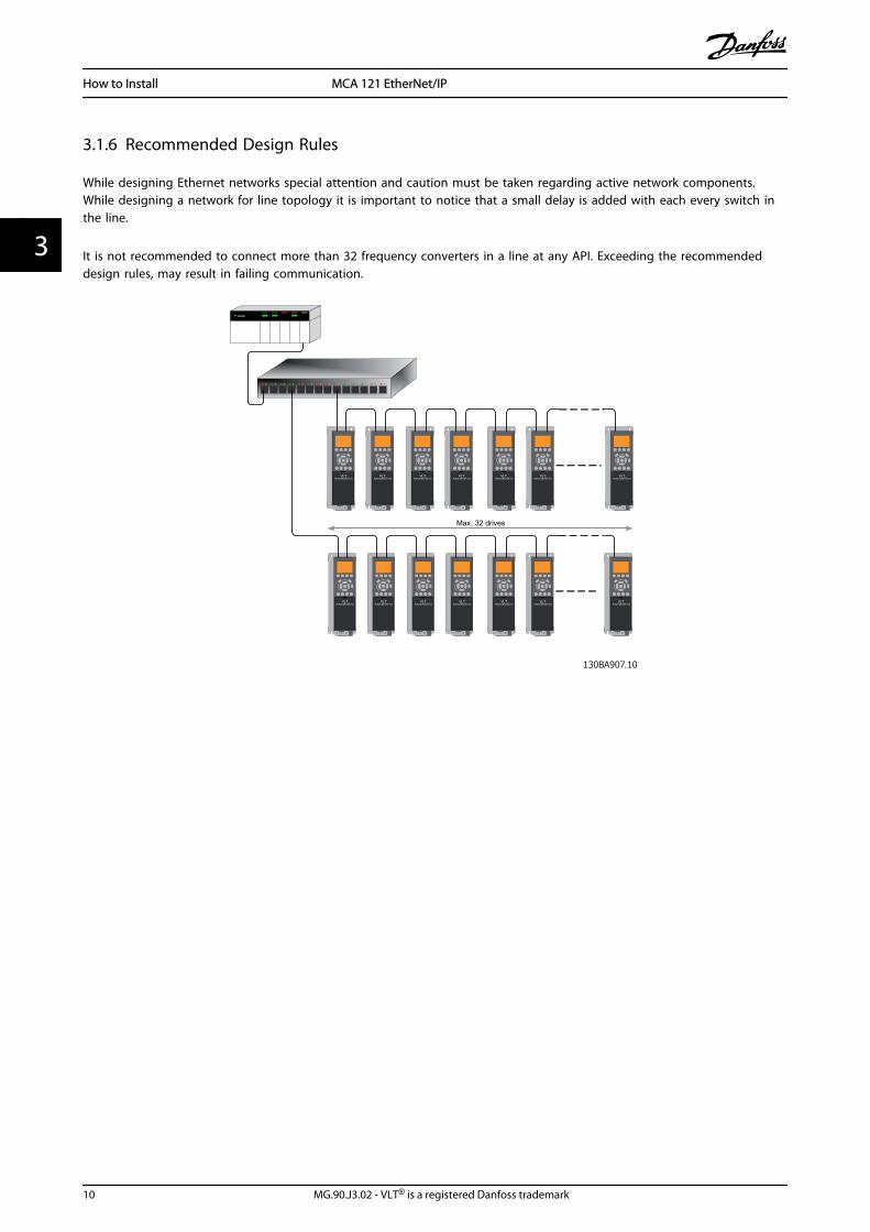
The event controlled operation mode is used to minimize network traffic. Messages are transmitted only if a defined state orvalue has changed. The condition for triggering a COS message, is determined by the insertion of COS-filters (12-38 COSFilter), for each bit in the different PCD-words.The filter acts like a logical AND-function: If a bit in the filter is set to “1”, the COS-function triggers when there is a changeto the corresponding bit for the PCD-word.
Parameter 12-38 COS Filter can be used to filter out undesired events for COS. If a filter bit is set to 0, the corresponding I/0Instance bit will be unable to produce a COS message. By default, all bits in the COS filters are set to 0.
In order to signal that the connection has not been interrupted, or the device is not powered off, a Heartbeat Message istransmitted within a specified time interval (Heartbeat Interval). This interval is defined in Attribute Heartbeat Time of theconnection object, Class 0x01.
To prevent the device from producing heavy network traffic when a value changes frequently, a Production Inhibit Time isdefined in 12-37 COS Inhibit Timer. This parameter defines the minimum time between two COS messages. If 12-37 COSInhibit Timer is set to 0, the Production Inhibit Timer is disabled.
Illustration 5.1 shows the different PCDs and their corresponding filter parameters.
How to Control MCA 121 EtherNet/IP
20 MG.90.J3.02 - VLT® is a registered Danfoss trademark
55

5.2 Danfoss FC Control Profile
5.2.1 Danfoss FC Control Profile
→
Illustration 5.1 (8-10 Control Word Profile = FC profile)
Bit Bit value = 0 Bit value = 1
00 Reference value External selection LSB
01 Reference value External selection MSB
02 DC brake Ramp
03 Coasting No coasting
04 Quick stop Ramp
05 Hold output frequency Use ramp
06 Ramp stop Start
07 No function Reset
08 No function Jog
09 Ramp 1 Ramp 2
10 Data invalid Data valid
11 No function Relay 01 active
12 No function Relay 04 active
13 Parameter set-up Selection LSB
14 Parameter set-up Selection MSB
15 No function Reverse
Explanation of Control BitsBits 00/01Bits 00 and 01 are used to choose between the fourreference values, which are pre-programmed in 3-10 PresetReference according to the following table:
Programmedref. value
Parameter Bit 01 Bit 00
1 3-10 [0] 0 0
2 3-10 [1] 0 1
3 3-10 [2] 1 0
4 3-10 [3] 1 1
NOTEIn 8-56 Preset Reference Select select a selection is made todefine how Bit 00/01 gates with the correspondingfunction on the digital inputs.
Bit 02, DC brake:Bit 02 = ‘0’ leads to DC braking and stop. Braking currentand duration are set in 2-01 DC Brake Current and 2-02 DCBraking Time. Bit 02 = ‘1’ leads to ramping, 3-41 Ramp 1Ramp up Time
Bit 03, Coasting:Bit 03 = ‘0’ causes the frequency converter to immediately"let go" of the motor (the output transistors are "shut off"),so that it coasts to a standstill.Bit 03 = ‘1’ enables the frequency converter to start themotor if the other starting conditions have been fulfilled.
NOTEIn 8-50 Coasting Select a selection is made to define howBit 03 gates with the corresponding function on a digitalinput.
Bit 04, Quick stop:Bit 04 = ‘0’ causes a stop, in which the motor speed isramped down to stop via 3-81 Quick Stop Ramp Time.
Bit 05, Hold output frequency:Bit 05 = ‘0’ causes the present output frequency (in Hz) tofreeze. The frozen output frequency can then be changedonly by means of the digital inputs (5-10 Terminal 18Digital Input to 5-15 Terminal 33 Digital Input) programmedto Speed up and Speed down.
NOTEIf Freeze output is active, the frequency converter can onlybe stopped by the following:
• Bit 03 Coasting stop
• Bit 02 DC braking
• Digital input (5-10 Terminal 18 Digital Input to5-15 Terminal 33 Digital Input) programmed to DCbraking, Coasting stop or Reset and coasting stop
How to Control MCA 121 EtherNet/IP
MG.90.J3.02 - VLT® is a registered Danfoss trademark 21
5 5

Bit 06, Ramp stop/start:Bit 06 = ‘0’ causes a stop, in which the motor speed isramped down to stop via the selected ramp downparameter. Bit 06 = ‘1’ permits the frequency converter tostart the motor, if the other starting conditions have beenfulfilled.
NOTEIn 8-53 Start Select Start select a selection is made to definehow Bit 06 Ramp stop/start gates with the correspondingfunction on a digital input.
Bit 07, Reset:Bit 07 = ‘0’ no reset. Bit 07 = ‘1’ resets a trip. Reset isactivated on the leading edge of the signal, i.e. whenchanging from logic ‘0’ to logic ‘1’.
Bit 08, Jog:Bit 08 = ‘1’ causes the output frequency to be determinedby 3-19 Jog Speed [RPM].
Bit 09, Selection of ramp 1/2:Bit 09 = ‘0’ means that ramp 1 is active (3-40 Ramp 1 Typeto 3-47 Ramp 1 S-ramp Ratio at Decel. Start). Bit 09 = ‘1’means that ramp 2 (3-50 Ramp 2 Type to 3-57 Ramp 2 S-ramp Ratio at Decel. Start) is active.
Bit 10, Data not valid/Data valid:This bit tells the frequency converter whether the controlword is to be used or ignored. Bit 10 = ‘0’ causes thecontrol word to be ignored, Bit 10 = ‘1’ causes the controlword to be used. The control word is always contained inthe telegram, regardless of which type of telegram is used,so this function is useful for ‘turning off’ the control wordwhen not required for updating or reading parameters.
Bit 11, Relay 01:Bit 11 = ‘0’ Relay not activated. Bit 11 = ‘1’ Relay 01activated, provided Control word bit 11 has been chosen in5-40 Function Relay.
Bit 12, Relay 02:Bit 12 = ‘0’ Relay 02 has not been activated. Bit 12 = ‘1’Relay 02 has been activated, provided Control word bit 12has been chosen in 5-40 Function Relay.
Bit 13/14, Selection of set-up:Bits 13 and 14 are used to select one of four menu set-upsaccording to the following table:
Set-up Bit 14 Bit 13
1 0 0
2 0 1
3 1 0
4 1 1
The function is only possible when Multi-Set-ups is selectedin 0-10 Active Set-up.
NOTEIn 8-55 Set-up Select a selection is made to define how Bit13/14 gates with the corresponding function on the digitalinputs.
Bit 15 Reverse:Bit 15 = ‘0’ causes no reversing. Bit 15 = ‘1’ causesreversing. Note: In the factory setting reversing is set todigital in 8-54 Reversing Select. Bit 15 causes reversing onlywhen Ser. communication, Logic AND or Logic OR isselected.
How to Control MCA 121 EtherNet/IP
22 MG.90.J3.02 - VLT® is a registered Danfoss trademark
55

5.2.2 Status Word according to FC Profile(STW)
→
Illustration 5.2 (8-10 Control Word Profile)
Bit Bit value = 0 Bit value = 1
00 Control not ready Control ready
01 Drive not ready Drive ready
02 Coasting Enable
03 No error Trip
04 No error Error (no trip)
05 Reserved -
06 No error Trip lock
07 No warning Warning
08 Speed ≠ reference Speed = reference
09 Local operation Bus control
10 Out of frequency limit Frequency limit ok
11 No operation In operation
12 Drive ok Stopped, auto start
13 Voltage ok Voltage exceeded
14 Torque ok Torque exceeded
15 Thermal ok Thermal exceeded
Explanation of the Status BitsBit 00, Control ready:Bit 00 = ‘0’ means that the frequency converter hastripped. Bit 00 = ‘1’ means that the frequency convertercontrols are ready, but that the power component is notnecessarily receiving any power supply (in the event ofexternal 24V supply to controls).
Bit 01, Drive ready:Bit 01 = ‘1’. The frequency converter is ready for operation.
Bit 02, Coasting stop:Bit 02 = ‘0’. The frequency converter has released themotor. Bit 02 = ‘1’. The frequency converter can start themotor when a start command is given.
Bit 03, No error/Trip:Bit 03 = ‘0’ means that the frequency converter is not infault mode. Bit 03 = ‘1’ means that the frequencyconverter is tripped, and that a reset signal is required tore-establish operation.
Bit 04, No error/Error (no trip):Bit 04 = ‘0’ means that the frequency converter is not infault mode. Bit 04 = ‘1’ means that there is a frequencyconverter error but no trip.
Bit 05, Reserved:
Bit 05 is not used in the status word.
Bit 06, No error / Trip lock:Bit 06 = ‘0’ means that the frequency converter is not infault mode. Bit 06 = ‘1’ means that the frequencyconverter is tripped, and locked.
Bit 07, No warning/Warning:Bit 07 = ‘0’ means that there are no warnings. Bit 07 = ‘1’means that a warning has occurred.
Bit 08, Speed≠ reference/Speed = reference:Bit 08 = ‘0’ means that the motor is running, but that thepresent speed is different from the preset speed reference.For example, this might occur while the speed is beingramped up/down during start/stop. Bit 08 = ‘1’ means thatthe present motor speed matches the preset speedreference.
Bit 09, Local operation/Bus control:Bit 09 = ‘0’ means that [STOP/RESET] is activated on thecontrol unit, or that Local control in 3-13 Reference Site isselected. It is not possible to control the frequencyconverter via serial communication. Bit 09 = ‘1’ means thatit is possible to control the frequency converter via thefieldbus/ serial communication.
Bit 10, Out of frequency limit:Bit 10 = ‘0’, if the output frequency has reached the valuein 4-11 Motor Speed Low Limit [RPM] or 4-13 Motor SpeedHigh Limit [RPM]. Bit 10 = ‘1’ means that the outputfrequency is within the defined limits.
Bit 11, No operation/In operation:Bit 11 = ‘0’ means that the motor is not running. Bit 11 =‘1’ means that the frequency converter has a start signal orthat the output frequency is greater than 0 Hz.
Bit 12, Drive OK/Stopped, auto start:Bit 12 = ‘0’ means that there is no temporary overtemperature on the inverter. Bit 12 = ‘1’ means that theinverter has stopped because of over temperature, butthat the unit has not tripped and will resume operationonce the over temperature stops.
Bit 13, Voltage OK/Voltage exceeded:Bit 13 = ‘0’ means that there are no voltage warnings. Bit13 = ‘1’ means that the DC voltage in the frequencyconverter’s intermediate circuit is too low or too high.
Bit 14, Torque OK/Torque limit exceeded:Bit 14 = ‘0’ means that the motor current is lower than thetorque limit selected in par. 4-16 and 4-17 Torque limit. Bit14 = ‘1’ means that the torque limit in par. 4-16 and 4-17Torque limit has been exceeded. The nominal torque canbe read in 16-16 Torque [Nm].
Bit 15, Thermal OK/limit exceeded:Bit 15 = ‘0’ means that the timers for both motor thermalprotection and frequency converter thermal protection,have not exceeded 100%. Bit 15 = ‘1’ means that one ofthe limits has exceeded 100%.
How to Control MCA 121 EtherNet/IP
MG.90.J3.02 - VLT® is a registered Danfoss trademark 23
5 5

5.3 ODVA Control Profile
5.3.1 Control Word under Instances 20/70and 21/71
Set 8-10 Control Word Profile to ODVA.
The control word in Instances 20 and 21 is defined asfollows:
→
NOTEBits 00 and 02 in Instance 20 are identical with bits 00 and02 in the more extensive Instance 21.
BitInstance 20 Instance 21
Bit = 0 Bit =1 Bit = 0 Bit =1
00 Stop Run Fwd Stop Run Fwd
01 - - Stop Run Rev
02 No function Fault reset No function Fault reset
03 - - - -
04 - - - -
05 - - - Net Ctrl
06 - - - Net Ref
07-15 - - - -
Explanation of the Bits:Bit 0, Run Fwd:Bit 0 = "0" means that the frequency converter has a stopcommand. Bit 0 = "1" leads to a start command and thefrequency converter will start to run the motor clockwise.
Bit 1, Run Rev:Bit 1 = "0" leads to a stop of the motor. Bit 1 = "1" leads toa start of the motor.
Bit 2, Fault Reset:Bit 2 = "0" means that there is no trip reset. Bit 2 = "1"means that a trip is reset.
Bit 3, No function:Bit 3 has no function.
Bit 4, No function:Bit 4 has no function.
Bit 5, Net Control:Bit 5 = "0" means that the frequency converter iscontrolled from the standard inputs. Bit 5 = "1" means thatEIP controls the frequency converter.
NOTEPlease note that changes will affect parameters 8-50 to8-56.
Bit 6, Net Reference:Bit 6 = "0" Reference is from the standard inputs. Bit 6 ="1" Reference is from EIP.
NOTEPlease note that changes will affect 3-15 Reference Resource1 to 3-17 Reference Resource 3. For the Speed reference, seesection Bus speed reference value under Instances 20/70 and21/71.
5.3.2 Status Word under Instances 20/70and 21/71
The status word in Instances 70 and 71 is defined asfollows:
→
NOTEBits 00 and 02 in Instance 70 are identical with bits 00 and02 in the more extensive Instance 71.
BitInstance 70 Instance 71
Bit = 0 Bit =1 Bit = 0 Bit =1
00 No Fault Fault No Fault Fault
01 - - - Warning
02 - Running 1Fwd
- Running 1 Fwd
03 - - - Running 2 Rev.
04 - - - Ready
05 - - - Ctrl from Net
06 - - - Ref. from Net
07 - - - At ref.
08-15 - - State Attribute
How to Control MCA 121 EtherNet/IP
24 MG.90.J3.02 - VLT® is a registered Danfoss trademark
55

Explanation of the Bits:Bit 0, Fault:Bit 0 = "0" means that there is no fault in the frequencyconverter. Bit 0 = "1" means that there is a fault in thefrequency converter.
Bit 1, Warning:Bit 0 = "0" means that there is no unusual situation. Bit 0 ="1" means that an abnormal condition has occurred.
Bit 2, Running 1:Bit 2 = "0" means that the frequency converter is not inone of these states or that Run 1 is not set. Bit 2 = "1"means that the frequency converter state attribute isenabled or stopping, or that Fault-Stop and bit 0 (Run 1)of the control word are set at the same time.
Bit 3, Running 2:Bit 3 = "0" means that the frequency converter is in neitherof these states or that Run 2 is not set. Bit 3 = "1" meansthat the frequency converter state attribute is enabled orstopping, or that fault-stop and bit 0 (Run 2) of the controlword are set at the same time.
Bit 4, Ready:Bit 4 = "0" means that the state attribute is in anotherstate. Bit 4 = "1" means that the state attribute is ready,enabled or stopping.
Bit 5, Control from net:Bit 5 = "0" means that the frequency converter iscontrolled from the standard inputs. Bit 5 = "1" means thatEIP has control (start, stop, reverse) of the frequencyconverter.
Bit 6, Ref from net:Bit 6 = "0" means that the reference comes from inputs tothe frequency converter. Bit 6 = "1" means that thereference comes from EIP.
Bit 7, At reference:Bit 7 = "0" means that the motor is running, but that thepresent speed is different from the preset speed reference,i.e. the speed is being ramped up/down during start/stop.Bit 7 = "1" means that the frequency converter andreference speeds are equal.
Bit 8 - 15, State attribute:(Instance 71 only) Represents the state attribute of thefrequency converter, as indicated in the following table:
Bit Number Meaning
8 Not used
9 Start up
10 Not ready
11 Ready
12 Enabled
13 Stopping
14 Fault stop
15 Faulted
For more detail of the actual output speed, see the sectionActual output speed under Instances 20/70 and 21/71.
How to Control MCA 121 EtherNet/IP
MG.90.J3.02 - VLT® is a registered Danfoss trademark 25
5 5
5.4 Reference Handling
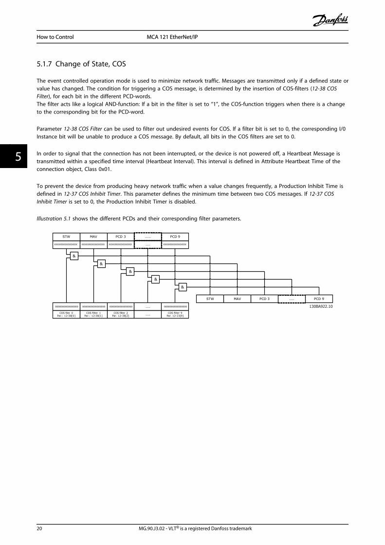
5.4.1 Bus Speed Reference Value
0% = 0hex
100% = 4000hex
-100% = C000hex
Depending of the setting of 3-00 Reference Range, the reference is scaled from – Max. to + Max. or from Min. to Max.
Reverse ForwardPar.3-00 set to
(1) -max- +max
Max reference Max reference
Par.3-00 set to
(0) min-max
Max reference
Forward
Min reference
100%
(4000hex)
-100%
(C000hex)
0%
(0hex)
Par.3-03 0 Par.3-03
Par.3-03
(4000hex)(0hex)
0% 100%
Par.3-02
130B
A27
7.10
The actual reference [Ref. %] in the frequency converter depends on the settings in the following parameters:
1-23 Motor Frequency
1-25 Motor Nominal Speed
3-02 Minimum Reference
3-03 Maximum Reference
All references provided to the frequency converter are added to the total reference value. If a reference is to be controlledby thefieldbus only, ensure that all other reference inputs are zero.
This means that digital and analogue input terminals should not be used for reference signals. The default setting (0%)should be maintained for preset references in 3-10 Preset Reference.
CAUTIONIf the bus speed reference is negative, and the control word contains a run reverse signal, the frequency converter will runclockwise (- - is +).
MAV is scaled in the same way as the reference.
How to Control MCA 121 EtherNet/IP
26 MG.90.J3.02 - VLT® is a registered Danfoss trademark
55

5.4.2 Bus Speed Value underInstances 20/70 and 21/71
→
The speed reference value should be transmitted to thefrequency converter in the form of a 16-bit word. Thevalue is transmitted directly in RPM.
How to Control MCA 121 EtherNet/IP
MG.90.J3.02 - VLT® is a registered Danfoss trademark 27
5 5

6 Parameters
6.1 Parameter Group 8-**
8-01 Control Site
Option: Function:
The setting in this parameter overridesthe settings in 8-50 Coasting Select to 8-56 Preset Reference Select.
[0] * Digital andctrl.word
Control by using both digital input andcontrol word.
[1] Digital only Control by using digital inputs only.
[2] Controlword only Control by using control word only.
8-02 Control Word Source
Select the source of the control word: one of two serial interfacesor four installed options. During initial power-up, the frequencyconverter automatically sets this parameter to Option A [3] if itdetects a valid fieldbus option installed in slot A. If the option isremoved, the frequency converter detects a change in theconfiguration, sets 8-02 Control Word Source back to defaultsetting RS-485, and the frequency converterr then trips. If anoption is installed after initial power-up, the setting of 8-02 Control Word Source will not change but the frequencyconverter will trip and display: Alarm 67 Option Changed.When you retrofit a bus option into a frequency converter, thatdid not have a bus option installed to begin with, you must takean ACTIVE decision to move the control to Bus based. This isdone for safety reasons in order to avoid an accidental change.This parameter cannot be adjusted while the motor is running.
Option: Function:
[0] None
[1] FC RS485
[2] FC USB
[3] * Option A
[4] Option B
[5] Option C0
[6] Option C1
[30] External Can
8-03 Control Word Timeout Time
Range: Function:
1.0 s* [Applicationdependant]
Enter the maximum time expected topass between the reception of twoconsecutive telegrams. If this time isexceeded, it indicates that the serialcommunication has stopped. Thefunction selected in 8-04 Control WordTimeout Function will then be carriedout. The time-out counter is triggered bya valid control word.
8-04 Control Word Timeout Function
Select the time-out function. The time-out function activateswhen the control word fails to be updated within the timeperiod specified in 8-03 Control Word Timeout Time.
Option: Function:
[0] * Off Resumes control via serial bus (fieldbus orstandard) using the most recent controlword.
[1] Freeze output Freezes output frequency until communi-cation resumes.
[2] Stop Stops with auto restart when communi-cation resumes.
[3] Jogging Runs the motor at JOG frequency untilcommunication resumes.
[4] Max. speed Runs the motor at maximum frequencyuntil communication resumes.
[5] Stop and trip Stops the motor, then resets the frequencyconverter in order to restart: via thefieldbus, via the reset button on the LCP orvia a digital input.
[7] Select setup 1 Changes the set-up upon reestablishment ofcommunication following a control wordtime-out. If communication resumes causingthe time-out situation to disappear, 8-05 End-of-Timeout Function defineswhether to resume the set-up used beforethe time-out or to retain the set-upendorsed by the time-out function.
[8] Select setup 2 See [7] Select setup 1
[9] Select setup 3 See [7] Select setup 1
[10] Select setup 4 See [7] Select setup 1
[26] Trip
NOTEThe following configuration is required in order to changethe set-up after a time-out:Set 0-10 Active Set-up to [9] Multi set-up and select therelevant link in 0-12 This Set-up Linked to.
8-05 End-of-Timeout Function
Option: Function:
Select the action after receiving a validcontrol word following a time-out. Thisparameter is active only when 8-04 ControlTimeout Function is set to [Set-up 1-4].
[0] Hold set-up Retains the set-up selected in 8-04 ControlTimeout Function and displays a warning,
Parameters MCA 121 EtherNet/IP
28 MG.90.J3.02 - VLT® is a registered Danfoss trademark
66

8-05 End-of-Timeout Function
Option: Function:until 8-06 Reset Control Timeout toggles. Thenthe frequency converter resumes its originalset-up.
[1] * Resume set-up
Resumes the set-up active prior to the time-out.
8-06 Reset Control Word Timeout
This parameter is active only when Hold set-up [0] has beenselected in 8-05 End-of-Timeout Function.
Option: Function:
[0] * Do not reset Retains the set-up specified in 8-04 ControlWord Timeout Function, following a controlword time-out.
[1] Do reset Returns the frequency converter to theoriginal set-up following a control word time-out. The frequency converter performs thereset and then immediately reverts to the Donot reset [0] setting
8-10 Control Word Profile
Select the interpretation of the control and status wordscorresponding to the installed fieldbus. Only the selections validfor the fieldbus installed in slot A will be visible in the LCPdisplay.For guidelines in selection of FC profile [0] and PROFIdrive profile[1] please refer to the Serial communication via RS 485 Interfacesection.For additional guidelines in the selection of PROFIdrive profile [1],ODVA [5] and CANopen DSP 402 [7], please refer to the OperatingInstructions for the installed fieldbus.
Option: Function:
[0] * FC profile
[1] PROFIdrive profile
[5] ODVA
[7] CANopen DSP 402
[8] MCO
8-13 Configurable Status Word STW
Option: Function:
This parameter enables configuration ofbits 12 – 15 in the status word.
[0] No function
[1] * Profile Default Function corresponds to the profiledefault selected in 8-10 Control Profile.
[2] Alarm 68 Only Only set in case of an Alarm 68.
[3] Trip excl Alarm68
Set in case of a trip, except if the trip isexecuted by an Alarm 68.
[10] T18 DI status. The bit indicates the status of terminal
18*1.
[11] T19 DI status. The bit indicates the status of terminal
19*1.
8-13 Configurable Status Word STW
Option: Function:
[12] T27 DI status. The bit indicates the status of terminal
27*1.
[13] T29 DI status. The bit indicates the status of terminal
29*1.
[14] T32 DI status. The bit indicates the status of terminal
32*1.
[15] T33 DI status. The bit indicates the status of terminal
33*1.
[16] T37 DI status The bit indicates the status of terminal
37*2.
[21] Thermalwarning
The thermal warning turns on when thetemperature exceeds the limit in themotor, the frequency converter, the brakeresistor, or the thermistor..
[30] Brake fault(IGBT)
Output is Logic ‘1’ when the brake IGBT isshort-circuited. Use this function toprotect the frequency converter if there isa fault on the brake modules. Use theoutput/relay to cut out the main voltagefrom the frequency converter.
[40] Out of refrange
[60] Comparator 0 See par. group 13-1*. If Comparator 0 isevaluated as TRUE, the output will gohigh. Otherwise, it will be low.
[61] Comparator 1 See par. group 13-1*. If Comparator 1 isevaluated as TRUE, the output will gohigh. Otherwise, it will be low.
[62] Comparator 2 See par. group 13-1*. If Comparator 2 isevaluated as TRUE, the output will gohigh. Otherwise, it will be low.
[63] Comparator 3 See par. group 13-1*. If Comparator 3 isevaluated as TRUE, the output will gohigh. Otherwise, it will be low.
[64] Comparator 4 See par. group 13-1*. If Comparator 4 isevaluated as TRUE, the output will gohigh. Otherwise, it will be low.
[65] Comparator 5 See par. group 13-1*. If Comparator 5 isevaluated as TRUE, the output will gohigh. Otherwise, it will be low.
[70] Logic Rule 0 See par. group 13-4*. If Logic Rule 0 isevaluated as TRUE, the output will gohigh. Otherwise, it will be low.
[71] Logic Rule 1 See par. group 13-4*. If Logic Rule 1 isevaluated as TRUE, the output will gohigh. Otherwise, it will be low.
[72] Logic Rule 2 See par. group 13-4*. If Logic Rule 2 isevaluated as TRUE, the output will gohigh. Otherwise, it will be low.
[73] Logic Rule 3 See par. group 13-4*. If Logic Rule 3 isevaluated as TRUE, the output will gohigh. Otherwise, it will be low.
Parameters MCA 121 EtherNet/IP
MG.90.J3.02 - VLT® is a registered Danfoss trademark 29
6 6

8-13 Configurable Status Word STW
Option: Function:
[74] Logic Rule 4 See par. group 13-4*. If Logic Rule 4 isevaluated as TRUE, the output will gohigh. Otherwise, it will be low.
[75] Logic Rule 5 See par. group 13-4*. If Logic Rule 5 isevaluated as TRUE, the output will gohigh. Otherwise, it will be low.
[80] SL DigitalOutput A
See par. 13-52 SL Controller Action. Theoutput will go high whenever the SmartLogic Action [38] Set dig. out. A high isexecuted. The output will go lowwhenever the Smart Logic Action [32] Setdig. out. A low is executed.
[81] SL DigitalOutput B
See par. 13-52 SL Controller Action. Theinput will go high whenever the SmartLogic Action [39] Set dig. out. A high isexecuted. The input will go low wheneverthe Smart Logic Action [33] Set dig. out. Alow is executed. [
[82] SL DigitalOutput C
See par. 13-52 SL Controller Action. Theinput will go high whenever the SmartLogic Action [40] Set dig. out. A high isexecuted. The input will go low wheneverthe Smart Logic Action [34] Set dig. out. Alow is executed.
[83] SL DigitalOutput D
See par. 13-52 SL Controller Action. Theinput will go high whenever the SmartLogic Action [41] Set dig. out. A high isexecuted. The input will go low wheneverthe Smart Logic Action [35] Set dig. out. Alow is executed.
[84] SL DigitalOutput E
See par. 13-52 SL Controller Action. Theinput will go high whenever the SmartLogic Action [42] Set dig. out. A high isexecuted. The input will go low wheneverthe Smart Logic Action [36] Set dig. out. Alow is executed.
[85] SL DigitalOutput F
See par. 13-52 SL Controller Action. Theinput will go high whenever the SmartLogic Action [43] Set dig. out. A high isexecuted. The input will go low wheneverthe Smart Logic Action [37] Set dig. out. Alow is executed.*1: “0” indicates that the terminal is low“1” indicates that the terminal is high*1: “0” indicates T37 is low (safe stop)“1” indicates T37 is high (normal)
8-14 Configurable Control Word CTW
Option: Function:
Selection of control word bit 10 if itis active low or active high
[0] None
[1] * Profile default
[2] CTW Valid, active low
8-14 Configurable Control Word CTW
Option: Function:
[3] Safe Option Reset
8-50 Coasting Select
Option: Function:
Select control of the coasting function via theterminals (digital input) and/or via the bus.
[0] Digitalinput
Activates Start command via a digital input.
[1] Bus Activates Start command via the serialcommunication port or fieldbus option.
[2] Logic AND Activates Start command via the fieldbus/serialcommunication port, AND additionally via oneof the digital inputs.
[3] * Logic OR Activates Start command via the fieldbus/serialcommunication port OR via one of the digitalinputs.
8-51 Quick Stop Select
Select control of the Quick Stop function via the terminals(digital input) and/or via the bus.
Option: Function:
[0] Digital input
[1] Bus
[2] Logic AND
[3] * Logic OR
8-52 DC Brake Select
Option: Function:
Select control of the DC brake via theterminals (digital input) and/or via thefieldbus.
[0] Digitalinput
Activates Start command via a digital input.
[1] Bus Activates Start command via the serialcommunication port or fieldbus option.
[2] Logic AND Activates Start command via the fieldbus/serialcommunication port, AND additionally via oneof the digital inputs.
[3] * Logic OR Activates Start command via the fieldbus/serialcommunication port OR via one of the digitalinputs.
8-53 Start Select
Option: Function:
Select control of the frequency converter startfunction via the terminals (digital input) and/orvia the fieldbus.
[0] Digitalinput
Activates Start command via a digital input.
[1] Bus Activates Start command via the serialcommunication port or fieldbus option.
Parameters MCA 121 EtherNet/IP
30 MG.90.J3.02 - VLT® is a registered Danfoss trademark
66

8-53 Start Select
Option: Function:
[2] Logic AND Activates Start command via the fieldbus/serialcommunication port, AND additionally via oneof the digital inputs.
[3] * Logic OR Activates Start command via the fieldbus/serialcommunication port OR via one of the digitalinputs.
8-54 Reversing Select
Option: Function:
[0] Digitalinput
Select control of the frequency converterreverse function via the terminals (digitalinput) and/or via the fieldbus.
[1] Bus Activates the Reverse command via the serialcommunication port or fieldbus option .
[2] Logic AND Activates the Reverse command via thefieldbus/serial communication port, ANDadditionally via one of the digital inputs.
[3] * Logic OR Activates the Reverse command via thefieldbus/serial communication port OR via oneof the digital inputs.
8-55 Set-up Select
Option: Function:
Select control of the frequency converter set-up selection via the terminals (digital input)and/or via the fieldbus.
[0] Digitalinput
Activates the set-up selection via a digitalinput.
[1] Bus Activates the set-up selection via the serialcommunication port or fieldbus option.
[2] Logic AND Activates the set-up selection via the fieldbus/serial communication port, AND additionallyvia one of the digital inputs.
[3] * Logic OR Activate the set-up selection via the fieldbus/serial communication port OR via one of thedigital inputs.
8-56 Preset Reference Select
Option: Function:
Select control of the frequency converterPreset Reference selection via the terminals(digital input) and/or via the fieldbus.
[0] Digitalinput
Activates Preset Reference selection via adigital input.
[1] Bus Activates Preset Reference selection via theserial communication port or fieldbus option.
[2] Logic AND Activates Preset Reference selection via thefieldbus/serial communication port, ANDadditionally via one of the digital inputs.
8-56 Preset Reference Select
Option: Function:
[3] * Logic OR Activates the Preset Reference selection via thefieldbus/serial communication port OR via oneof the digital inputs.
6.2 Parameter Group 12-**
6.2.1 12-0* IP Settings
12-00 IP Address Assignment
Option: Function:
Selects the IP Address assignment method.
[0] * Manual IP-address can be set in12-01 IP Address IP Address.
[1] DHCP IP-address is assigned via DHCP server.
[2] BOOTP IP-address is assigned via BOOTP server.
12-01 IP Address
Range: Function:
[000.000.000.000 -255.255.255.255]
Configure the IP address of theoption. Read-only if 12-00 IP AddressAssignment set to DHCP or BOOTP.
12-02 Subnet Mask
Range: Function:
[000.000.000.000 -255.255.255.255]
Configure the IP subnet mask of theoption. Read-only if 12-00 IP AddressAssignment set to DHCP or BOOTP.
12-03 Default Gateway
Range: Function:
[000.000.000.000 –255.255.255.255]
Configure the IP default gateway ofthe option. Read-only if 12-00 IPAddress Assignment set to DHCP orBOOTP.
12-04 DHCP Server
Range: Function:
[000.000.000.000 –255.255.255.255]
Read only. Displays the IP addressof the found DHCP or BOOTPserver.
NOTEA power-cycle is necessary after setting the IP parametersmanually.
12-05 Lease Expires
Range: Function:
Application dependent* [Application dependant]
Parameters MCA 121 EtherNet/IP
MG.90.J3.02 - VLT® is a registered Danfoss trademark 31
6 6

12-06 Name Servers
Range: Function:
0* [0 - 2147483647 ] IP addresses of Domain Name Servers.Can be automatically assigned whenusing DHCP.
12-07 Domain Name
Range: Function:
0 [0 - 2147483647 ] Domain name of the attached network.Can be automatically assigned whenusing DHCP.
12-08 Host Name
Range: Function:
Blank [0-19 characters] Logical (given) name of option.
12-09 Physical Address
Range: Function:
0* [0 - 0 ] Read only Displays the Physical (MAC) address ofthe option.
6.2.2 12-1* Ethernet Link Parameters
12-1* Ethernet Link parameters
Option: Function:
Applies for whole parameter group.
[0] Port 1
[1] Port 2
12-10 Link Status
Option: Function:
12-11 Link Duration
Range: Function:
Application dependent* [Application dependant]
12-12 Auto Negotiation
Option: Function:
Configures Auto Negotiation of Ethernet linkparameters, for each port: ON or OFF.
[0] Off Link Speed and Link Duplex can be configured in12-13 Link Speed and 12-14 Link Duplex.
[1] On
12-13 Link Speed
Option: Function:
Forces the link speed for each port in 10 or 100Mbps. If 12-12 Auto Negotiation is set to: ON,this parameter is read only and displays theactual link speed. “None” is displayed if no linkis present.
[0] * None
[1] 10 Mbps
[2] 100 Mbps
12-14 Link Duplex
Option: Function:
Forces the duplex for each port to Full or Halfduplex. If 12-12 Auto Negotiation is set to: ON,this parameter is read only.
[0] Half Duplex
[1] * Full Duplex
6.2.3 12-2* Process Data
12-20 Control Instance
Range: Function:
[None, 20, 21, 100,101, 103]
Read only. Displays the originator-to-target connection point. If no CIPconnection is present “None” isdisplayed.
12-21 Process Data Config Write
Range: Function:
[[0 - 9] PCD read 0 - 9] Configuration of readable processdata.
NOTEFor configuration of 2-word (32-bit) parameter read/write,use 2 consecutive arrays in 12-21 Process Data Config Writeand 12-22 Process Data Config Read.
12-22 Process Data Config Read
Range: Function:
[[0 - 9] PCD read 0 - 9] Configuration of readable processdata.
12-28 Store Data Values
Option: Function:
This parameter activates a function that storesall parameter values in the non-volatilememory (EEPROM) thus retaining parametervalues at power-down.The parameter returns to “Off”.
[0] * Off The store function is inactive.
[1] Store Allset-ups
All parameter value will be stored in the non-volatile memory, in all four setups.
12-29 Store Always
Option: Function:
Activates function that will always store receivedparameter data in non-volatile memory (EEPROM).
[0] * Off
[1] On
Parameters MCA 121 EtherNet/IP
32 MG.90.J3.02 - VLT® is a registered Danfoss trademark
66

6.2.4 12-3* EtherNet/IP
12-30 Warning parameter
Range: Function:
[0000 –FFFF hex]
Read only. Displays the EtherNet/IP specific 16-bitStatus-word.
Bit Description
0 Owned
1 Not used
2 Configured
3 Not used
4 Not used
5 Not used
6 Not used
7 Not used
8 Minor recoverable fault
9 Minor unrecoverable fault
10 Major recoverable fault
11 Major unrecoverable fault
12 Not used
13 Not used
14 Not used
15 Not used
12-31 Net Reference
Option: Function:
Read only. Displays the reference source in Instance21/71.
[0] * Off Reference from the network is not active.
[1] On Reference from the network is active.
12-32 Net Control
Option: Function:
Read only. Displays the control source in Instance21/71.
[0] * Off Control via the network is not active.
[1] On Control via the network is active
12-33 CIP Revision
Option: Function:
Read only. Displays the CIP-versionof the option software.
[0] Major version (00 - 99)
[1] Minor version (00 - 99)
12-34 CIP Product Code
Range: Function:
1100 (FC 302) 1110(FC 301)*
[0 – 9999] Read only. Displays the CIPproduct code.
12-37 COS Inhibit Timer
Range: Function:
[0 – 65.535ms]
Read only Change-Of-State inhibit timer. If theoption is configured for COS operation, thisinhibit timer can be configured in the ForwardOpen telegram to prevent that continuouslychanging PCD data generates extensive networktraffic. The inhibit time is in milliseconds, 0 =disabled.
12-38 COS Filters
Range: Function:
[[0 - 9] Filter 0 – 9(0000 - FFFFhex)]
Change-Of-State PCD filters. Sets up afilter mask for each word of processdata when operating in COS-mode.Single bits in the PCD’s can be filteredin/out.
6.2.5 12-80 Other Ethernet Services
12-80 FTP Server
Option: Function:
12-81 HTTP Server
Option: Function:
12-82 SMTP Service
Option: Function:
12-89 Transent Socket Channel Port
Range: Function:
0* [0 – 9999] Configures the TCP port-number for the transentsocket channel. This enables FC-telegrams to besent transently on Ethernet via TCP. Defaultvalue is 4000, 0 means disabled.
12-90 Cable Diagnostic
Option: Function:
Enables/disables advanced Cable diagnosisfunction. If enabled, the distance to cable errorscan be read out in 12-93 Cable Error Length. Theparameter resumes to the default setting ofDisable after the diagnostics have finished.
[0] * Disabled
[1] Enabled
NOTEThe cable diagnostics function will only be issued on portswhere there is no link (see 12-10 Link Status, Link Status)
12-91 Auto Cross-Over
Option: Function:
[0] Disable Disables the auto cross-over function.
[1] * Enable Enables the auto cross-over function.
Parameters MCA 121 EtherNet/IP
MG.90.J3.02 - VLT® is a registered Danfoss trademark 33
6 6

NOTEDisabling of the auto cross-over function will requirecrossed Ethernet cables for daisy-chaining the options.
12-93 Cable Error Length
Range: Function:
0* [0 -65535 ]
If Cable Diagnostics is enabled in EN-90 CableDiagnostic, the built-in switch is possible viaTime Domain Reflectometry (TDR). This is ameasurement technique which detects commoncabling problems such as open circuits, shortcircuits and impedance mismatches or breaks intransmission cables. The distance from theoption to the error is displayed in metres withan accuracy of +/- 2m. The value 0 means noerrors detected.
12-94 Broadcast Storm Protection
Range: Function:
-1%*
[-1 -20 %]
The built-in switch is capable of protecting theswitch system from receiving too many broadcastpackages, which can use up network resources.The value indicates a percentage of the totalbandwidth that is allowed for broadcast messages.
Example:The “OFF” means that the filter is disabled - allbroadcast messages will be passed through. Thevalue “0%” means that no broadcast messages willbe passed through. A value of “10%” means that10% of the total bandwidth is allowed forbroadcast messages, if the amount of broadcastmessages increases above the 10% threshold, theywill be blocked.
12-95 Broadcast Storm Filter
Option: Function:
Applies to 12-94 Broadcast StormProtection; if the Broadcast StormProtection should also includeMulticast telegrams.
[0] * Broadcast only
[1] Broadcast &Multicast
12-98 Interface Counters
Range: Function:
4000* [0 - 4294967296 ] Read only. Advanced Interfacecounters, from built-in switch, can beused for low-level trouble-shooting,The parameter shows a sum of port 1+ port 2.
12-99 Media Counters
Range: Function:
0* [0 - 4294967296 ] Read only. Advanced Interface counters,from built-in switch, can be used for low-level trouble-shooting, The parametershows a sum of port 1 + port 2.
Parameters MCA 121 EtherNet/IP
34 MG.90.J3.02 - VLT® is a registered Danfoss trademark
66

6.3 Parameter List
Par.No. #
Parameter description Default value 4-set-up FC 302only
Changeduring
operation
Conver-sion
index
Type
8-0* General Settings
8-01 Control Site [0] Digital and ctrl.word All set-ups TRUE - Uint8
8-02 Control Word Source null All set-ups TRUE - Uint8
8-03 Control Word Timeout Time 1.0 s 1 set-up TRUE -1 Uint32
8-04 Control Word Timeout Function null 1 set-up TRUE - Uint8
8-05 End-of-Timeout Function [1] Resume set-up 1 set-up TRUE - Uint8
8-06 Reset Control Word Timeout [0] Do not reset All set-ups TRUE - Uint8
8-07 Diagnosis Trigger [0] Disable 2 set-ups TRUE - Uint8
8-08 Readout Filtering null All set-ups TRUE - Uint8
8-1* Ctrl. Word Settings
8-10 Control Word Profile [0] FC profile All set-ups TRUE - Uint8
8-13 Configurable Status Word STW null All set-ups TRUE - Uint8
8-14 Configurable Control Word CTW [1] Profile default All set-ups TRUE - Uint8
8-3* FC Port Settings
8-30 Protocol [0] FC 1 set-up TRUE - Uint8
8-31 Address 1 N/A 1 set-up TRUE 0 Uint8
8-32 FC Port Baud Rate null 1 set-up TRUE - Uint8
8-33 Parity / Stop Bits [0] Even Parity, 1 Stop Bit 1 set-up TRUE - Uint8
8-34 Estimated cycle time 0 ms 2 set-ups TRUE -3 Uint32
8-35 Minimum Response Delay 10 ms All set-ups TRUE -3 Uint16
8-36 Max Response Delay ExpressionLimit 1 set-up TRUE -3 Uint16
8-37 Max Inter-Char Delay ExpressionLimit 1 set-up TRUE -5 Uint16
8-4* FC MC protocol set
8-40 Telegram selection [1] Standard telegram 1 2 set-ups TRUE - Uint8
8-41 Parameters for signals 0 All set-ups FALSE - Uint16
8-42 PCD write configuration ExpressionLimit All set-ups TRUE 0 Uint16
8-43 PCD read configuration ExpressionLimit All set-ups TRUE 0 Uint16
8-5* Digital/Bus
8-50 Coasting Select [3] Logic OR All set-ups TRUE - Uint8
8-51 Quick Stop Select [3] Logic OR All set-ups TRUE - Uint8
8-52 DC Brake Select [3] Logic OR All set-ups TRUE - Uint8
8-53 Start Select [3] Logic OR All set-ups TRUE - Uint8
8-54 Reversing Select [3] Logic OR All set-ups TRUE - Uint8
8-55 Set-up Select [3] Logic OR All set-ups TRUE - Uint8
8-56 Preset Reference Select [3] Logic OR All set-ups TRUE - Uint8
8-57 Profidrive OFF2 Select [3] Logic OR All set-ups TRUE - Uint8
8-58 Profidrive OFF3 Select [3] Logic OR All set-ups TRUE - Uint8
8-8* FC Port Diagnostics
8-80 Bus Message Count 0 N/A All set-ups TRUE 0 Uint32
8-81 Bus Error Count 0 N/A All set-ups TRUE 0 Uint32
8-82 Slave Messages Rcvd 0 N/A All set-ups TRUE 0 Uint32
8-83 Slave Error Count 0 N/A All set-ups TRUE 0 Uint32
8-9* Bus Jog
8-90 Bus Jog 1 Speed 100 RPM All set-ups TRUE 67 Uint16
8-91 Bus Jog 2 Speed ExpressionLimit All set-ups TRUE 67 Uint16
Parameters MCA 121 EtherNet/IP
MG.90.J3.02 - VLT® is a registered Danfoss trademark 35
6 6

Par.No.#
Parameter description Default value 4-set-up FC 302only
Changeduring
operation
Conver-sion
index
Type
12-0* IP Settings
12-00 IP Address Assignment null 2 set-ups TRUE - Uint8
12-01 IP Address 0 N/A 1 set-up TRUE 0 OctStr[4]
12-02 Subnet Mask 0 N/A 1 set-up TRUE 0 OctStr[4]
12-03 Default Gateway 0 N/A 1 set-up TRUE 0 OctStr[4]
12-04 DHCP Server 0 N/A 2 set-ups TRUE 0 OctStr[4]
12-05 Lease Expires ExpressionLimit All set-ups TRUE 0 TimD
12-06 Name Servers 0 N/A 1 set-up TRUE 0 OctStr[4]
12-07 Domain Name 0 N/A 1 set-up TRUE 0 VisStr[48]
12-08 Host Name 0 N/A 1 set-up TRUE 0 VisStr[48]
12-09 Physical Address 0 N/A 1 set-up TRUE 0 VisStr[17]
12-1* Ethernet Link Parameters
12-10 Link Status [0] No Link All set-ups TRUE - Uint8
12-11 Link Duration ExpressionLimit All set-ups TRUE 0 TimD
12-12 Auto Negotiation [1] On 2 set-ups TRUE - Uint8
12-13 Link Speed [0] None 2 set-ups TRUE - Uint8
12-14 Link Duplex [1] Full Duplex 2 set-ups TRUE - Uint8
12-2* Process Data
12-20 Control Instance ExpressionLimit 1 set-up TRUE 0 Uint8
12-21 Process Data Config Write ExpressionLimit All set-ups TRUE - Uint16
12-22 Process Data Config Read ExpressionLimit All set-ups TRUE - Uint16
12-23 Process Data Config Write Size 16 N/A All set-ups TRUE 0 Uint32
12-24 Process Data Config Read Size 16 N/A All set-ups TRUE 0 Uint32
12-27 Primary Master 0 N/A 1 set-up FALSE 0 OctStr[4]
12-28 Store Data Values [0] Off All set-ups TRUE - Uint8
12-29 Store Always [0] Off 1 set-up TRUE - Uint8
12-3* EtherNet/IP
12-30 Warning Parameter 0 N/A All set-ups TRUE 0 Uint16
12-31 Net Reference [0] Off 2 set-ups TRUE - Uint8
12-32 Net Control [0] Off 2 set-ups TRUE - Uint8
12-33 CIP Revision ExpressionLimit All set-ups TRUE 0 Uint16
12-34 CIP Product Code ExpressionLimit 1 set-up TRUE 0 Uint16
12-35 EDS Parameter 0 N/A All set-ups TRUE 0 Uint32
12-37 COS Inhibit Timer 0 N/A All set-ups TRUE 0 Uint16
12-38 COS Filter 0 N/A All set-ups TRUE 0 Uint16
12-4* Modbus TCP
12-40 Status Parameter 0 N/A All set-ups TRUE 0 Uint16
12-41 Slave Message Count 0 N/A All set-ups TRUE 0 Uint32
12-42 Slave Exception Message Count 0 N/A All set-ups TRUE 0 Uint32
12-5* EtherCAT
12-50 Configured Station Alias 0 N/A 1 set-up FALSE 0 Uint16
12-51 Configured Station Address 0 N/A All set-ups TRUE 0 Uint16
12-59 EtherCAT Status 0 N/A All set-ups TRUE 0 Uint32
12-8* Other Ethernet Services
12-80 FTP Server [0] Disabled 2 set-ups TRUE - Uint8
12-81 HTTP Server [0] Disabled 2 set-ups TRUE - Uint8
12-82 SMTP Service [0] Disabled 2 set-ups TRUE - Uint8
12-89 Transparent Socket Channel Port ExpressionLimit 2 set-ups TRUE 0 Uint16
12-9* Advanced Ethernet Services
12-90 Cable Diagnostic [0] Disabled 2 set-ups TRUE - Uint8
12-91 Auto Cross Over [1] Enabled 2 set-ups TRUE - Uint8
Parameters MCA 121 EtherNet/IP
36 MG.90.J3.02 - VLT® is a registered Danfoss trademark
66

Par.No.#
Parameter description Default value 4-set-up FC 302only
Changeduring
operation
Conver-sion
index
Type
12-92 IGMP Snooping [1] Enabled 2 set-ups TRUE - Uint8
12-93 Cable Error Length 0 N/A 1 set-up TRUE 0 Uint16
12-94 Broadcast Storm Protection -1 % 2 set-ups TRUE 0 Int8
12-95 Broadcast Storm Filter [0] Broadcast only 2 set-ups TRUE - Uint8
12-96 Port Config null 2 set-ups TRUE - Uint8
12-98 Interface Counters 4000 N/A All set-ups TRUE 0 Uint32
12-99 Media Counters 0 N/A All set-ups TRUE 0 Uint32
6.4 Data Types
6.4.1 Data Types Supported by FC202/FC300
Conversion IndexThis number to the left refers to a conversion figure on theright to be used when writing or reading parameters.
Conversion Index Conversion Factor
67 1/60
6 1000000
5 100000
4 10000
3 1000
2 100
1 10
0 1
-1 0.1
-2 0.01
-3 0.001
-4 0.0001
-5 0.00001
-6 0.000001
Parameters MCA 121 EtherNet/IP
MG.90.J3.02 - VLT® is a registered Danfoss trademark 37
6 6

7 Troubleshooting
7.1.1 Step-by-step Troubleshooting
Check: LEDsThe option contains two LEDs to indicate the state of the device and the network. During normal operation the MS and atleast one NS LED will show a constant green light.
State LED Description
Standby Green: Flashing green The device needs commissioning
Device operational Green: Solid green The device is operational
Major recoverable fault Flashing red The device has detected a recoverable fault (MAR)
Major unrecoverablefault
Red: Solid red The device has detected a un-recoverable fault(MAU)
Self testRed: Flashing red/
greenThe EIP option is in self-test mode
Green:
Table 7.1 MS: Module Status
State LED Description
No connections Green: Flashing green There are no established any CIP connections tothe device
Connected Green: Solid green There is established (at least) one CIP connection tothe device
Connection time-out Red: Flashing red One or more CIP connections has timed-out
Duplicate IP Red: Solid red The IP-address assigned to the device is already inuse
Self testRed: Flashing red/
greenThe EIP option is in self-test mode
Green
Table 7.2 NS1 + NS2: Network Status (one per port)
Check: Link StatusThe status of the Ethernet link cannot be directly identified by means of the LEDs, if no CIP connection is established.Use 12-10 Link Status to verify presents of the link.Use 12-11 Link Duration to verify that the link is steady present.The parameter will show the duration of the present link, and preset to 00:00:00:00 if the link is broken.
Check: CablingIn rare cases of cabling mis-configuration, the option might show the presents of a link, but no communication is running.Exchange the cable in doubt.
Check: IP AddressVerify that the option has a valid IP address (please refer to section: IP Settings) in 12-01 IP Address. If the option hasidentified a duplicate IP Address NS LEDs will light steady red. If the option is set up for BOOTP or DHCP, verify that aBOOTP or DHCP server is connected in 12-04 DHCP Server. If no server is connected, the parameter will show:000.000.000.000.
7.1.2 Alarm Word and Warning Word
Alarm word and warning word are shown in the display in Hex format. If there is more than one warning or alarm, a sum ofall warnings or alarms will be shown. Warning word and alarm word are displayed in 16-90 Alarm Word to 16-95 Ext. StatusWord 2. For more information on the individual alarms and warnings, please refer to the frequency converter Design Guide.
Troubleshooting MCA 121 EtherNet/IP
38 MG.90.J3.02 - VLT® is a registered Danfoss trademark
77

NOTEPlease note that the availability of the individual alarms and warnings are dependent on the frequency converter type.
Warning and Alarm MessagesThere is a clear distinction between alarms and warnings. In the event of an alarm, the frequency converter will enter a faultcondition. After the cause for the alarm has been cleared, the master must acknowledge the alarm message in order to startoperation of the frequency converter again. A warning, on the other hand, may appear when a warning condition arises,then disappear when conditions return to normal without interfering with the process.
WarningsAll warnings within the frequency converter are represented by a single bit within a warning word. A warning word isalways an action parameter. Bit status FALSE [0] means no warning, while bit status TRUE [1] means warning. Each bit statushas a corresponding text string message. In addition to the warning word message the master will also be notified via achange in the status word.
AlarmsFollowing an alarm message the frequency converter will enter a fault condition. Only after the fault has been rectified andthe master has acknowledged the alarm message by a bit in the Control Word, can the frequency converter resumeoperation. All alarms within the frequency converter are represented by a single bit within an alarm word. An alarm word isalways an action parameter. Bit status FALSE [0] means no alarm, while bit status TRUE [1] means alarm. In CIP, Alarms aredivided in to two categories:
- Major Recoverable Faults
- Major Unrecoverable Faults
Please refer to the following sections for a classification of the specific faults.
Troubleshooting MCA 121 EtherNet/IP
MG.90.J3.02 - VLT® is a registered Danfoss trademark 39
7 7

Bit (Hex) Alarm word (Par. 16-90) CIP Classification
00000001 Brake check -
00000002 Power card over temperature MAR
00000004 Earth fault MAU
00000008 Ctrl. card over temperature -
00000010 Control word timeout MAR
00000020 Torque limit MAU
00000040 Over current MAR
00000080 Motor thermistor over temp. MAR
00000100 Motor ETR over temperature MAR
00000200 Inverter overloaded MAR
00000400 DC link under voltage MAR
00000800 DC link over voltage MAR
00001000 Short circuit MAU
00002000 Inrush fault MAR
00004000 Mains phase loss MAU
00008000 AMA not OK MAR
00010000 Live zero error MAR
00020000 Internal fault MAU
00040000 Brake overload MAU
00080000 Motor phase U is missing MAU
00100000 Motor phase V is missing MAU
00200000 Motor phase W is missing MAU
00400000 fieldbus fault MAR
00800000 24V supply fault MAU
01000000 Mains failure MAR
02000000 1.8V supply fault MAU
04000000 Brake resistor short circuit MAR
08000000 Brake chopper fault MAR
10000000 Option change -
20000000 Drive initialized -
40000000 Safe Stop MAR
80000000 Mech. Brake low -
MAR = Major Recoverable FaultMAU = Major Unrecoverable Fault
Troubleshooting MCA 121 EtherNet/IP
40 MG.90.J3.02 - VLT® is a registered Danfoss trademark
77

Bit (Hex) Alarm word 2 (Par 16-91)
00000001 Service Trip, Read/Write
00000002 Reserved
00000004 Service Trip, Typecode/Sparepart
00000008 Reserved
00000010 Reserved
00000020 No Flow
00000040 Dry Pump
00000080 End of Curve
00000100 Broken Belt
00000200 Discharge high
00000400 Start failed
00000800 Speed limit
00001000 Reserved
00002000 Reserved
00004000 Reserved
00008000 Reserved
00010000 Reserved
00020000 KTY error
00040000 Fans error
00080000 ECB error
00100000 Reserved
00200000 Reserved
00400000 Reserved
00800000 Reserved
01000000 Reserved
02000000 Reserved
04000000 Reserved
08000000 Reserved
10000000 Reserved
20000000 Reserved
40000000 PTC thermistor
80000000 Dangerous failure
Bit (Hex) Warning word (Par. 16-92)
00000001 Brake check
00000002 Power card over temperature
00000004 Earth fault
00000008 Control card over temperature
00000010 Control word timeout
00000020 Over current
00000040 Torque limit
00000080 Motor thermistor over temp.
00000100 Motor ETR over temperature
00000200 Inverter overloaded
00000400 DC link under voltage
00000800 DC link over voltage
00001000 DC link voltage low
00002000 DC link voltage high
00004000 Mains phase loss
00008000 No motor
00010000 Live zero error
00020000 10V low
00040000 Brake resistor power limit
00080000 Brake resistor short circuit
00100000 Brake chopper fault
00200000 Speed limit
00400000 fieldbus comm. fault
00800000 24V supply fault
01000000 Mains failure
02000000 Current limit
04000000 Low temperature
08000000 Voltage limit
10000000 Encoder loss
20000000 Output frequency limit
40000000 Safe stop
80000000 Extended status word
Troubleshooting MCA 121 EtherNet/IP
MG.90.J3.02 - VLT® is a registered Danfoss trademark 41
7 7

Bit (Hex) Warning word 2 (Par. 16-93)
00000001 Start Delayed
00000002 Stop Delayed
00000004 Clock Failure
00000008 Firemode was active
00000010 Reserved
00000020 No Flow
00000040 Dry Pump
00000080 End of Curve
00000100 Broken Belt
00000200 Discharge high
00000400 Reserved
00000800 Reserved
00001000 Reserved
00002000 Reserved
00004000 Reserved
00008000 Reserved
00010000 Reserved
00020000 KTY warning
00040000 Fans warning
00080000 ECB warning
00100000 Reserved
00200000 Reserved
00400000 Reserved
00800000 Reserved
01000000 Reserved
02000000 Reserved
04000000 Reserved
08000000 Reserved
10000000 Reserved
20000000 Reserved
40000000 PTC thermistor
80000000 Reserved
Bit (Hex) Extended status word (Par.16-94) FC 200 only !!
00000001 Ramping
00000002 AMA Running
00000004 Start CW/CCW
00000008 Slow Down
00000010 Catch Up
00000020 Feedback high
00000040 Feedback low
00000080 Output current high
00000100 Output current low
00000200 Output frequency high
00000400 Output frequency low
00000800 Brake check OK
00001000 Braking max
00002000 Braking
00004000 Out of speed range
00008000 OVC active
00010000 AC brake
00020000 Password Timelock
00040000 Password Protection
00080000 Reference high
00100000 Reference low
00200000 Local Ref./Remote Ref.
00400000 Reserved
00800000 Reserved
01000000 Reserved
02000000 Reserved
04000000 Reserved
08000000 Reserved
10000000 Reserved
20000000 Reserved
40000000 Reserved
80000000 Reserved
Troubleshooting MCA 121 EtherNet/IP
42 MG.90.J3.02 - VLT® is a registered Danfoss trademark
77

Bit (Hex) Extended status word 2 (Par.16-95)
FC 200 only !!
00000001 Off
00000002 Hand/Auto
00000004 PROFIbus OFF1 active
00000008 PROFIbus OFF2 active
00000010 PROFIbus OFF3 active
00000020 Relay 123 active
00000040 Start Prevented
00000080 Control ready
00000100 Drive ready
00000200 Quick Stop
00000400 DC Brake
00000800 Stop
00001000 Stand By
00002000 Freeze Output Request
00004000 Freeze Output
00008000 Jog Request
00010000 Jog
00020000 Start Request
00040000 Start
00080000 Start Applied
00100000 Start Delay
00200000 Sleep
00400000 Sleep Boost
00800000 Running
01000000 Bypass
02000000 Fire Mode
04000000 Reserved
08000000 Reserved
10000000 Reserved
20000000 Reserved
40000000 Reserved
80000000 Reserved
Troubleshooting MCA 121 EtherNet/IP
MG.90.J3.02 - VLT® is a registered Danfoss trademark 43
7 7
8 Appendix
8.1.1 Supported CIP Objects
As in all implementations of CIP, EtherNet/IP shares the common Object Model. Objects are a common method to describethe specific application implemented in a device.
Data is structured in Classes, Instances and Attributes:
A class is a group of objects with the same structure. These groups of objects within a class are called instances. Everyinstance provides the same data elements called attributes. Each class provides services to access data or to change thestate of an object.
Class ID 0x01 Identity Object
Attribute Access Name Data type Description
1 Get Vendor UINT (97) Danfoss Drives vendor code
2 Get Device Type UINT (2) AC Drive
3 Get Product Code UINT Value of 12-34 CIP Product Code
4 Get Revision Struct Value of 12-33 CIP Revision
5 Get Status WORD EIP status word (12-30 WarningParameter)
6 Get Serial Number UDINT Serial number
7 Get Product Name String Value of 15-40 FC Type (e.g. “FC 302”)
8 Get State UINT 0 = Non-existent1 = Device Self Testing2 = Standby3 = Operational4 = Major Recoverable Fault5 = Major Unrecoverable Fault6-254 = Reserved255 = Default for Get Attribute All
9 Get Conf. consistency value UINT
Table 8.1 Instance Attributes
Class ID 0x04 Assembly ObjectsInstance Access Name Size Description
20 Set ODVA basic speed control Output 2 Words
21 Set ODVA extended speed control Output 2 Words
70 Get ODVA basic speed control Input 2 Words
71 Get ODVA extended speed control Input 2 Words
100 Set Danfoss Basic Control Output 2 Words
101 Set Danfoss Extended Control Output 4 Words
103 Set Danfoss Extended Control Output 10 Words
150 Get Danfoss Basic Control Input 2 Words
151 Get Danfoss Extended Control Input 4 Words
153 Get Danfoss Extended Control Input 10 Words
Table 8.2 Instance Attributes
Appendix MCA 121 EtherNet/IP
44 MG.90.J3.02 - VLT® is a registered Danfoss trademark
88

Class ID 0x06 Connection ManagerAttribute Access Name Data Type Description
1 Get Open Requests UINT Number of Forward Open requests received
2 Get Open Format Rejects UINT Number of Forward Open requests rejected due to badformat
3 Get Open Resource Rejects UINT Number of Forward Open requests rejected due to lack ofresources
4 Get Open Other Rejects UINT Number of Forward Open requests rejected due to otherreasons
5 Get Close Requests UINT Number of Forward Close requests received
6 Get Close Format Requests UINT Number of Forward Close requests rejected due to badformat
7 Get Close Other Requests UINT Number of Forward Close requests rejected due to otherreasons
8 Get Connection Timeouts UINT Number of connection timeouts
9 Get Connection Entry List Struct of:NumConnEntries
INT Number of connection entries ConnOpenBits ARRAY of BOOLList of connection data
Table 8.3 Instance Attributes
Class ID 0x28 Motor Data ObjectAttribute Access Name Data Type Parameter Description
1 Get Number of Attributes supported USINT - 7
2 Get List of attributes supported Array of USINT - 3,6,7,8,9,12,15
3 Get/Set Motor Type USINT 1-10 3: PM sync. motor (FC 302 only)7: Squirrel cage induction motor
6 Get/Set Rated Current UINT 1-24 Unit: 100 mA
7 Get/Set Rated Voltage UINT 1-22 Unit: Volt
8 Get/Set Rated Power UDINT 1-20 Unit: Watt
9 Get/Set Rated Frequency UINT 1-23 Unit: Hertz
12 Get/Set Pole Count UINT 1-39 Number of poles in motor
15 Get/Set Base Speed UINT 1-25 Unit: RPM
Table 8.4 Instance Attributes
NOTEClass ID 0x28 is only available if ODVA profile is selected in 8-10 Control Word Profile.
Appendix MCA 121 EtherNet/IP
MG.90.J3.02 - VLT® is a registered Danfoss trademark 45
8 8

Class ID 0x29 Control Supervisor ObjectAttribute Access Name Data Type Description
1 Get Number of Attributes supported USINT 12
2 Get List of supported Attributes Array of USINT 3,4,4,5,6,7,8,9,10,11,12,13,15
3 Get/Set Run 1 (forward) Boolean FC CTW Bit 6 = Run1 XOR Run2FC CTW Bit15 = 0
4 Get/Set Run 2 (reverse) Boolean FC CTW Bit 6 = Run1 XOR Run2FC CTW Bit15 = 1
5 Get/Set Network Control Boolean Parameter 12-32 value written from option
6 Get State USINT The state of the CIP state-machine
7 Get Running 1 Boolean Run1 AND bit 11 in FC STW
8 Get Running 2 Boolean Run2 AND bit 11 in FC STW
9 Get Ready Boolean STATE_ENABLED or STATE_STOPPING orSTATE_FAULT_STOP from state-machine
10 Get Faulted Boolean Bit 3 in FC STW
11 Get Warning Boolean Bit 7 in FC STW
12 Get/Set Fault reset Boolean Bit 7 in FC CTW
13 Get Fault Code UINT Mapping of 16-90 Alarm Word to CIP specific faultcodes
15 Get Control from net Boolean Parameter 12-31 value written from option
Table 8.5 Instance Attributes
Appendix MCA 121 EtherNet/IP
46 MG.90.J3.02 - VLT® is a registered Danfoss trademark
88
CIP MalfunctionCode
Meaning frequency converter-CodeAlarmword
CIP Malfunction Meaning CIP Classification
0 No alarm 0000 0000 No fault -
0 unused 0000 0001 No fault -
4210 frequency converter overtemperature
0000 0002 Excessive Device Temperature mar
2240 Earth fault 0000 0004 Short to earth mau
0 unused 0000 0008 No fault -
8100 Controlword timeout 0000 0010 Communication mir
2310 Overcurrent 0000 0020 Continuous Overcurrent mau
8302 Torque limit 0000 0040 Torque limiting mar
4310 Motor thermistor 0000 0080 Excessfrequency converterTemperature
mar
4310 Motor ETR over temp 0000 0100 Excess frequency converterTemperature
mar
2311 Inverter overloaded 0000 0200 Current inside the device, No. 1 mar
3220 DC Link undervoltage 0000 0400 Undervoltage inside the Device mar
3210 DC Link overvoltage 0000 0800 Overvoltage inside the device mar
2130 Short circuiting 0000 1000 Short Circuit mau
2213 Inrush fault 0000 2000 Overcurr. marduring startup
3130 Mains phase loss 0000 4000 Phase Failure mau
5210 AMT fail 0000 8000 Measurement Circuit mir
1000 Live zero fault 0001 0000 General fault mar
6100 Internal fault 0002 0000 Internal software fault mau
7110 Brake resistor power limit 0004 0000 Brake Chopper mau
3300 Motor phase U missing 0008 0000 Output voltage mau
3300 Motor phase V missing 0010 0000 Output voltage mau
3300 Motor phase W missing 0020 0000 Output voltage mau
8100 fieldbus fault 0040 0000 Communication mir
5112 24V supply fault 0080 0000 +24V Power supply mau
3100 Mains failure 0100 0000 Mains Voltage mar
5110 1,8V supply fault 0200 0000 Low voltage power supp. mau
7110 Brake resist. short circ. 0400 0000 Brake chopper mar
7110 Brake chopper fault 0800 0000 Brake chopper mar
0 unused 1000 0000 No fault -
0 unused 2000 0000 No fault -
0 unused 4000 0000 No fault -
0 unused 8000 0000 No fault -
Table 8.6 Attribute 13 “Fault Code”
Mir = Minor RecoverableMar = Major RecoverableMau = Major Unrecoverable
Service Code Service Name Service Description
0Eh Get_Attribute_Single Returns contents of specified attribute
10h Set_Attribute_Single Sets the contents of specified attribute
05h Reset Resets frequency converter to its start-up state.
Table 8.7 Services supported
NOTEClass ID 0x29 is only available if ODVA profile is selected in 8-10 Control Word Profile.
Appendix MCA 121 EtherNet/IP
MG.90.J3.02 - VLT® is a registered Danfoss trademark 47
8 8

Class ID 0x2A AC/DC Drive ObjectAttribute Access Rule Information about Data Type Contents
1 Get Number of AttributesSupported
USINT 12
2 Get List of Attributes Supported USINT 3,4,6,7,8,18,19,20,21,22,28,29
3 Get At Reference Boolean Bit 8 of FC STW
4 Get/Set Network Reference Boolean value written to parameter "Net Reference"
6 Get/Set Drive Mode USINT Mapping of values from 1-00 Configuration Mode
7 Get Actual Speed INT See Attribute 22
8 Get/Set Reference Speed INT See Attribute 22
18 Get/Set Acceleration Time UINT Scaled with Attribute 28 and written to 3-41 Ramp 1Ramp up Time
19 Get/Set Deceleration time UINT Scaled with Attribute 28 and written to 3-42 Ramp 1Ramp Down Time
20 Get/Set Low Speed Limit UINT Scaled with Attribute 22 and written to 4-11 MotorSpeed Low Limit [RPM]
21 Get/Set High Speed Limit UINT Scaled with Attribute 22 and written to 4-13 MotorSpeed High Limit [RPM]
22 Get/Set Speed Scale SINT Forms the "Speed Reference" and "Main Actual Value"for the frequency converter together with Attribute 7and 8
28 Get/Set Time Scale SINT Scaling factor for all time attributes
29 Get Ref From Net Boolean value of parameter "Net Reference"
Table 8.8 Instance Attributes
Value of Attribute 6 ODVA Text Value of 1-00 Configuration Mode FC Text
0 Vendor specific Remaining values not listed below ?
1 Open loop speed ctr. 0 Speed open loop
2 Closed loop speed ctr. 1 Speed closed loop
3 Torque Control NA NA
4 Process Control NA NA
5 Position Control NA NA
Table 8.9 Attribute 6 “Drive Mode”
NOTEClass ID 0x2A is only available if ODVA profile is selected in 8-10 Control Word Profile.
Appendix MCA 121 EtherNet/IP
48 MG.90.J3.02 - VLT® is a registered Danfoss trademark
88

Class ID 0xF5 Interface ObjectAttribute Access Rule Name Data Type Description of Attribute Parameter In
frequencyconverter
1 Get Status DWORD Interface status -
2 Get Configuration Capability DWORD Interface capability flags -
3 Get/Set Configuration Control DWORD Interface control flags -
4 Get
Physical Link Object STRUCT of: Path to physical link object -
Path size UINT Size of Path -
Path Padded EPATH Logical segments identifying the physicallink object
-
5 Get/Set
Interface Configuration STRUCT of: TCP/IP network interface configuration. -
IP Address UDINT The device’s IP address. 12-01
Network Mask UDINT The device’s network mask. 12-02
Gateway Address UDINT Default gateway address 12-03
Name Server UDINT Primary name server 12-06 [0]
Name Server 2 UDINT Secondary name server 12-06[1]
Domain Name STRING Default domain name 12-07
6 Get/Set Host Name STRING Host name 12-08
Table 8.10 Instance Attributes
Appendix MCA 121 EtherNet/IP
MG.90.J3.02 - VLT® is a registered Danfoss trademark 49
8 8

Class ID 0xF6 Link ObjectThree instances of the Link Object are implemented:
- Instance 1 and 2 relates to the physical Port 1 and 2 of the option.
- Instance 3 relates to the internal interface of the option, after the build-in switch.
Attribute
AccessRule
Name Data Type Description of Attribute Parameterinfrequencyconverter
1 Get Interface Speed UDINT Interface speed in Mbps (e.g., 0, 10, 100, 1000, etc.) 12-13
2 Get Interface Flags DWORD Interface status flags -
3 Get Physical Address ARRAY of 6USINTs
MAC layer address 12-09
4 Get
Interface Counters STRUCT of
In Octets UDINT Octets received on the interface 12-98 [0]
In Ucast Packets UDINT Unicast packets received on the interface 12-98[1]
In NUcast Packets UDINT Non-unicast packets received on the interface 12-98[2]
In Discards UDINT Inbound packets received on the interface but discarded 12-98[3]
In Errors UDINT Inbound packets that contain errors (does not include InDiscards)
12-98 [4]
In Unknown Protos UDINT Inbound packets with unknown protocol 12-98[5]
Out Octets UDINT Octets sent on the interface 12-98[6]
Out Ucast Packets UDINT Unicast packets sent on the interface 12-98[7]
Out NUcast Packets UDINT Non-unicast packets sent on the interface 12-98[8]
Out Discards UDINT Outbound packets discarded 12-98[9]
Out Errors UDINT Outbound packets that contain errors 12-98[10]
5
Get
Media Counters STRUCT of: Media-specific counters
Alignment Errors UDINT Frames received that are not an integral number of octets inlength
12-99[0]
FCS Errors UDINT Frames received that do not pass the FCS check 12-99[1]
Single Collisions UDINT Successfully transmitted frames which experienced exactly onecollision
12-99[2]
Multiple Collisions UDINT Successfully transmitted frames which experienced more thanone collision
12-99[3]
SQE Test Errors UDINT Number of times SQE test error message is generated 12-99[4]
DeferredTransmissions
UDINT Frames for which first transmission attempt is delayed becausethe medium is busy
12-99[5]
Late Collisions UDINT Number of times a collision is detected later than 512 bit timesinto the transmission of a packet
12-99[6]
Excessive Collisions UDINT Frames for which transmission fails due to excessive collisions 12-99[7]
MAC TransmitErrors
UDINT Frames for which transmission fails due to an internal MAC sublayer transmit error
12-99[8]
Carrier Sense Errors UDINT Times that the carrier sense condition was lost or never assertedwhen attempting to transmit a frame
12-99[9]
Frame Too Long UDINT Frames received that exceed the maximum permitted frame size 12-99[10]
MAC Receive Errors UDINT Frames for which reception on an interface fails due to aninternal MAC sub layer receive error
12-99[11]
6 Set Interface Control STRUCT of: Configuration for physical interface -
Control Bits WORD Interface Control Bits -
Forced InterfaceSpeed
UINT Speed at which the interface shall be forced to operate Speed inMbps (10, 100, 1000, etc.)
-
7 Get Interface Label SHORT_STRING Human readable identification -
8 Get Link List Size USINT Number of members in Link List -
Appendix MCA 121 EtherNet/IP
50 MG.90.J3.02 - VLT® is a registered Danfoss trademark
88

Attribute
AccessRule
Name Data Type Description of Attribute Parameterinfrequencyconverter
9 Get Link List ARRAY OF UINT Link List between internal and all according external interfaces -
Table 8.11 Instance Attributes
Service Code Supported Service Name Description of Service
Class Instance
01h Yes Yes Get_Attribute_All Returns a predefined listing of this objects attributes
0Eh Yes Yes Get_Attribute_Single Returns the contents of the specified attribute.
10h - Yes Set_Attribute_Single Modifies a single attribute.
43h - Yes Get_and_Clear Gets then clears the specified attribute (InterfaceCounters or Media Counters).
Table 8.12 Services supported
Appendix MCA 121 EtherNet/IP
MG.90.J3.02 - VLT® is a registered Danfoss trademark 51
8 8

Class ID 0x0F Parameter ObjectAttribute Access Rule Name Data Type Description of Attribute Contents
1 Get Revision UINT revision of object 01
2 Get Max Instance UINT max instance number variable
3 Get Number of instances UINT amount of instances variable
8 Get Parameter Class Descriptor WORD Parameter description 0x03
9 Get Configuration AssemblyInstance
UINT instance number of the configurationassembly
0
10 Get/Set Native Language USINT Language ID for all character array accesses variable
Table 8.13 Class attributes
Attribute
AccessRule
Name Data type Description Value
1 Set/Get Parameter Value data type described in Attr.5
actual value of parameter Value of parameter fromfrequency converter
2 Get Link path size USINT Size of link path variable
3 Get Link path ARRAY: CIP path of parameter’s origin variable
Segment type/port BYTE
Segment Address path
4 Get Descriptor WORD Description of parameter See Standard
5 Get Data Type EPATH Data type code -
6 Get Data size USINT Number of bytes in parameter value variable
7 Get Parameter namestring
SHORT STRING human readable text stringrepresenting parameter name
Parameter Attribute Fromfrequency converter
8 Get Units string SHORT STRING human readable text stringrepresenting parameter unit
Parameter Attribute Fromfrequency converter
9 Get Help String SHORT STRING human readable text stringrepresenting short online help.
Parameter Attribute Fromfrequency converter
10 Get min value data type described in Attr.5
Generic min valid value Parameter Attribute Fromfrequency converter
11 Get max value data type described in Attr.5
Generic max valid value Parameter Attribute Fromfrequency converter
12 Get default value data type described in Attr.5
Generic parameter’s default value Parameter Attribute Fromfrequency converter
13 Get Scaling multiplier UINT multiplier for scaling factor 1
14 Get Scaling divisor UINT divisor for scaling factor 1
15 Get Scaling base UINT base for scaling formula 0
16 Get Scaling offset INT offset for scaling formula 0
17 Get Multiplier link UINT parameter instance of multipliersource
0
18 Get divisor link UINT parameter instance of divisor source 0
19 Get base link UINT parameter instance of base source 0
20 Get offset link UINT parameter instance of offset source 0
21 Get decimal precision USINT specifies parameter value format variable
Table 8.14 Instance attributes
Appendix MCA 121 EtherNet/IP
52 MG.90.J3.02 - VLT® is a registered Danfoss trademark
88

Service Code Supported Service Name Description of Service
Class Instance
0Eh Yes Yes Get_Attribute_Single returns contents of specified attribute
01h Yes Yes Get_Attributes_All returns predefined listing of object attributes
10h No Yes Set_Attribute_Single modifies attribute
4Bh No Yes Get_Enum_String reads enumerated strings from parameterinstance
Table 8.15 Services supported
Class ID 0x10 Parameter Group ObjectAttribute Access
RuleName Data Type Description Contents
1 Get Group Name String SHORT_STRING represents group name Name of Group fromfrequency converter
2 Get Number of group members UINT amount of parameters in group value of n
3 Get 1st group parameter(000-099)
UINT instance number of ParameterObject
variable
4 Get 2nd group parameter(100-199)
UINT instance number of ParameterObject
variable
… Get … UINT … variable
n+2 Get nth group parameter UINT instance number of ParameterObject
variable
Table 8.16 Instance Attributes
Class ID 0x64 – 0xC7 Danfoss ObjectsThe CIP Class ID 100 to 199 (0x64 to 0xC7) gives access to all parameters.
Class (decimal) Danfoss Parameter range
100 0-01 - 0-99
101 1-00 – 1-99
102 2-00 – 2-99
103 3-00 – 3-99
104 4-00 – 4-99
105 5-00 – 5-99
106 6-00 – 6-99
107 7-00 – 7-99
108 8-00 – 8-99
109 9-00 – 9-99
110 10-00 – 10-99
111 11-00 – 11-99
… …
199 99-00 – 99-99
The class Instance and Attribute acts in the following way:
- 100 added to the parameter group = the valuefor the class.
- 100 added to the remaining parameter number =the value for the instance.
- 100 added to the array index of the parameter =the value for the attribute
Examples: (fictitious parameters)
- Parameter 0-01 [index 0] = Class 100; Instance101; Attribute 100
- Parameter 1-00 [index 0] = Class 101; Instance100; Attribute 100 - Parameter 2-59[index 0] =Class 102; Instance 159; Attribute 100
- Parameter 5-34[index 3] = Class 105; Instance 134;Attribute 103
- Parameter 6-54 [index 9] = Class 106; Instance154; Attribute 109
- Parameter 10-01 [index 0] = Class 110; Instance101; Attribute 100
All values in decimal.
All parameters are accessed in the Active setup (0-10 ActiveSet-up)
Appendix MCA 121 EtherNet/IP
MG.90.J3.02 - VLT® is a registered Danfoss trademark 53
8 8

Service Code Supported Service Name Description of Service
Class Instance
0Eh Yes Yes Get_Attribute_Single returns contents of specified attribute
10h No Yes Set_Attribute_Single modifies attribute
4Bh No Yes Get_Att_Scattered returns specified parameter values
4Ch No Yes Set_Att_Scattered sets specified parameter values
Table 8.17 Services supported
Appendix MCA 121 EtherNet/IP
54 MG.90.J3.02 - VLT® is a registered Danfoss trademark
88

Index
AAbbreviations........................................................................................... 5
AC/DC Drive Object............................................................................. 48
Alarm Word............................................................................................. 38
AssemblyInstances...................................................................................... 18, 17Objects................................................................................................. 44
Assumptions............................................................................................. 4
BBackground Knowledge....................................................................... 4
CCabling.............................................................................................. 34, 38
Change-Of-State............................................................................ 18, 33
CIP Objects....................................................................................... 18, 44
Class1 Connection..................................................................................... 183 Connection..................................................................................... 18
ConfigurationConfiguration............................................... 4, 14, 17, 28, 29, 5, 32Assembly Instance........................................................................... 52Capability............................................................................................ 49
Control Supervisor Object................................................................. 46
Conversion Index.................................................................................. 37
DDanfoss Objects.................................................................................... 53
DataType............................................... 44, 52, 45, 46, 48, 49, 50, 52, 53Types.................................................................................................... 37
DC Backup............................................................................................. 4, 5
EEDS............................................................................................................. 14
EMC Precautions................................................................................... 11
Ethernet................................. 11, 12, 14, 16, 32, 0 , 32, 33, 34, 38
EtherNet/IP...................................................... 4, 14, 15, 16, 17, 33, 44
FFC Profile........................................................................................... 17, 23
Forward Open................................................................... 15, 18, 33, 45
HHardware............................................................................................... 3, 4
II/O................................................................................................... 5, 17, 18
Identity Object....................................................................................... 44
IGMP.......................................................................................................... 16
Installation................................................................................... 3, 4, 5, 6
Interface Object..................................................................................... 49
IPSettings......................................................................................... 12, 38Traffic.................................................................................................... 16
IP21 / Type 1......................................................................................... 4, 5
LLED........................................................................................................... 5, 7
LEDs........................................................................................................... 38
Link Object....................................................................................... 49, 50
Literature.................................................................................................... 4
MMaster................................................................................................ 39, 14
Motor Data Object............................................................................... 45
Multicast.................................................................................... 18, 16, 34
NNetwork....................... 4, 11, 16, 20, 32, 33, 34, 38, 49, 7, 9, 46, 48
OObject Model......................................................................................... 44
ODVAConformance....................................................................................... 5Profile..................................................................................... 45, 47, 48
Overview.................................................................................................... 6
PParameter
Group Object..................................................................................... 53Object............................................................................................ 52, 53
Parameters.............................................................. 3, 12, 53, 12, 14, 18
RRedundancy............................................................................................ 16
Reference................... 19, 21, 23, 25, 5, 21, 24, 26, 0 , 33, 42, 48
SSafety........................................................................................................... 3
Spanning Tree.......................................................................................... 5
TTopology.................................................................................. 8, 10, 16, 8
Index MCA 121 EtherNet/IP
MG.90.J3.02 - VLT® is a registered Danfoss trademark 55

Troubleshooting................................................................................... 38
UUnconnected Messages..................................................................... 18
WWarning Word.......................................................................... 41, 42, 38
Index MCA 121 EtherNet/IP
56 MG.90.J3.02 - VLT® is a registered Danfoss trademark

MAKING MODERN LIVING POSSIBLE
OOperating InstructionsMCA 121 EtherNet/IP
www.danfoss.com/drives
*MG90J302*130R0430 MG90J302 Rev. 2011-03-29