Embed Size (px)
Citation preview

1
OPERATING INSTRUCTION FOR HEATING HOSES Electrically heating hose system V. 02/2010

2
INDEX Construction ............................................................................................................ 3 Safety level: Thermal safety .................................................................................... 3 Safety Instructions ................................................................................................... 4 Installation Instructions ............................................................................................ 4 Commissioning......................................................................................................... 5 Pressure Hoses ....................................................................................................... 6 Correction factors.................................................................................... ................ 6 Placing Instructions.................................................................................................. 7 Placing Instructions ................................................................................................. 8 Placing Instructions ................................................................................................. 9 Note on Fittings ......................................................................................................10 Maintenance and Repair ........................................................................................10 Technical data / Tolerances....................................................................................10 Warranty.................................................................................................................10 Appendix ................................................................................................................11 Handling of heated hoses when used for industrial robots.....................................11 Instructions for exchanging replaceable inner cores.............................................. 12 Manual addendum for the installation, implementation and operating of heating tubes within the hazardous area....................................................... .....12 Hose accessories.................................................................................................. . 13 Electronic temperature control.................................................................................14 Quality management............................................................................................... 15 Contact ................................................................................................................... 15

3
CONSTRUCTION
The thermal insulation can be selected according to the operating temperature or by outer environmental effects and is protected against mechanical damage by an outside protective braid. On both ends, silicone caps or polyamide hard caps are mounted. Usually, a standard plug as a standard feature for connection to our temperature control (see page 10), is mounted with the leads for heating, temperature sensor and control lines or the individual conductors are marked appropriately. Before using the heating hose, carefully read and observe the safety and installation instructions. Safety level: Thermal safety Level 0: No safety equipment only controlled operation – an overheating because of
design feature is excluded (Regulator) Level 1: With temperature regulator or – watcher (clicker) Level 2: With adjustable temperature regulator or –watcher (temperature regulator
and delimiter combination)
As a rule, the heating hose consists of a high-quality PTFE inner hose through which the liquid or gaseous medium flows. The inner hoses are resistant to high temperatures up to 250°C, high operating pressures and aggressive substances to cover a wide range of applications. Selection of the type of pressure hose can be accomplished on the basis of the operating pressure required (see list on page 5). The appropriate fitting can be press-fitted to the basic hose. Please observe that the inner diameter of the fitting is not identical with the nominal width of the hose and therefore restricts the hose passage. The heating conductor is laid out according to VDE guidelines, is protected against moisture and the protective conductor is protected by a braided jacket. A temperature sensor is installed to control the operating temperature of the heated hose – as a standard feature; the sensor is located approximately 300 mm in back of the electrical outlet. If additional control lines or single-wire conductors are required, they can also be incorporate into the heating hose.

4
SAFETY INSTRUCTIONS When planning, installing; testing and operating as well as for repair, always observe:
» these operating instructions
» DIN EN 60519-1 "Safety in Electrical heating systems" Part 1 : General requirements ( = IEC 519-1 = VDE 0721, Part 911) » applicable part of VDE 100 » as well as other standards and regulations applicable for such applications
» all recognized rules of technology such as EN standards, VDE0100, Low-Voltage Guidelines EN 60204, Part 1, Machine Guidelines EN 292 and the Accident Prevention Regulations according to BGV A2
Ensure that protection against dangerous body currents are provided as specified in VDE 0100, Part 410 and Part 540 (Grounding and System Grounding) as well as the specifications and the standards listed above. Ensure that the heating hose is installed only outside of explosion-hazard areas. It is not permissible to heat explosive mediums or mediums which release explosive gases when heated! Proper and safe operation of the heating hose assumes that the hose has been carefully transported, stored and properly installed. Ensure that heating hoses are installed and put into operation only by qualified personnel. Observe these operating instructions and operation of the device, particularly instructions and notes on routing, the applicable safety precautions for installation and operation of electrical equipment. Installation Instructions Please read these installation instructions carefully and observe all points listed when installing the equipment. Failure to observe these installation instructions can result in malfunctions or, under certain conditions, the required EMC Guidelines may not be fulfilled. Before connection and use of the heating hose, ensure that the operating voltage and the required operating voltage conditions for the heating hose conform with the local conditions (see type plate and technical data). Ensure that the load voltage is switched off on site and secure against being switched back on while installing the heating hose. Complete electrical connections in conformance with the connection diagram and applicable, electric-technical regulations. Route the supply lines to the heating hose so that they are free of tension under all conditions and cannot be pinched or sheared off under any circumstances. If possible, use shielded cable for the sensor lines and signal lines and shielded compensation lines for the thermocouples. Fuse the heating hose load circuit against excessive current. These instructions do not contain all information on regulations, standards, etc. to be observed when working on heating hose in combination with systems. It is the responsibility of the operator of the equipment to compile and observe these regulations and standards, etc. as required for the specific application.

5
COMMISSIONING
Before putting the heating hose into operation, observe the following: » Specifications on type plate must coincide with your order data » Use only temperature controls compatible with the type of sensor in the heating hose. » Ensure that the line voltage coincides with the voltage specified on the type plate. » Ensure that the nominal power for the heating hose does not exceed the maximum power output of the connected temperature control or power output from the equipment (resistive load). » Never operate the heating hose without temperature sensor (connected to temperature control), because otherwise it heats up without control and exceeds the maximum operating temperature which can lead to damage to the heating hose and your equipment. » Provide for a protective system to protect the line against excessive temperature in the event of overload. Line protection according to VDE 0721, Part 1, Section 19, must ensure that the nominal value of the fuse is matched to the specific load and must be connected in series in front of the heating hose (including control). However, the max. fuse rating must not exceed 16A. We recommend using a conductor with a cross section of at least 1.5mm² » If the heating hose is suspended or fastened with clamps, ensure that the outer diameter of the heating hose is not reduced by more than 10%. » Ensure that connection fittings are not under tension, under any circumstances. » It is necessary for the heating hose to reach its operating temperature before it is subjected to your operating pressure, because the medium could still be rigid at the fittings. » The time required to heat up the heating hose to operating temperature is approx. 15-30 minutes, as a rule. As soon as the hose reaches his operating temperature the fittings have to be tightening again. When starting up the system for the first time or restarting; ensure that the medium in the heating hose has reached its processing temperature to avoid damage to the inner hose. » Observe minimum bending radiuses! (see page 5). » Kinks and high torsion loads lead to destruction of the heating hose. » Observe placing instructions (see pages 6 to 8) » The resistance of the flexible heating hoses to pressure changes at various operating temperatures (see list on page 5). In the range up to 250°C, the pressure resistance can be specified, however, this decreases down to 0 bars at temperatures above 250°C. The maximum operating pressure should be calculated with a corresponding correction factor, depending on the maximum operating temperature. Also observe pressure surges. These can be very high and are not indicated by normal pressure gauges. Never exceed the operating pressure! » Hoses and PTFE tubing up to NW 8 have been tested for their suitability for use with vacuum down to 8 mbar at temperatures up to 250°C.

6
PRESSURE HOSES
T1 Smooth PTFE hose with one woven layer of stainless steel wire (DIN 1.4301) nominal temperature 250°C
Nominal diameter DN 4 6 8 10 12 16 20 25
Working pressure in bar 275 240 200 175 150 135 100 80
Burst pressure in bar 1100 920 800 700 600 540 400 320
min. bending radius in mm 50 75 100 120 135 160 200 250
T2 Smooth PTFE hose with two woven layers of stainless steel wire (DIN 1.4301) nominal temperature 250°C
Nominal diameter DN 6 8 10 12 16 20 25 32 40
Working pressure in bar 275 250 225 200 175 150 130 70 50
Burst pressure in bar 1100 1000 900 800 700 600 520 280 200
min. bending radius in mm 75 100 120 135 160 200 250 500 850
T3 Smooth PTFE hose with two layers of high tensile steel wires and one braided steel wire nominal temperature 250°C
Nominal diameter DN 6 8 10 12 16 20 25 32
Working pressure in bar 500 475 450 400 400 300 275 250
Burst pressure in bar 2000 1900 1800 1600 1600 1200 1000 1000
min. bending radius in mm 75 100 120 135 160 200 240 280
CORRECTION FACTORS for different operating temperatures The specified pressures apply for operating temperatures from 20°C to 50°C. Specifications or correction factors must be observed if using under different temperatures as follows:
Operating temperature up to 24°C 100°C 200 °C 250°C Temperature correction factor 1,0 0,9 0,8 0,6

7
PLACING INSTRUCTIONS WRONG CORRECT
Dragging at the ends of the rolled-up heated Unwind the roll instead of pulling the heated hose. hoses causes torsional stress, as well as too narrow a minimum bending radius.
If heated hoses are too short, the heated hose Plan in a straight piece of heated hose will be kinked at the connections. (about 5 x hose diameter) at the connections.
A wide bending radius ensures a longer durability.
The heated hoses are often destroyed Make sure the axes of the heated hose by torsional motions caused by improper run parallel and the motions are always installation. on one and the same level.

8
PLACING INSTRUCTIONS WRONG CORRECT
Avoid diversions, for they may cause kinking Use a saddle-shaped device or a roll, and bending stress. each with the appropriate diameter.
Any inappropriate installation makes Use a spiral heated hose suspension. the heated hose sag.
Heated hoses mounted within a closed channel Heated hoses must not touch each other. or shaft will cause heat built-up. Sufficient ventilation is to be provided.
9
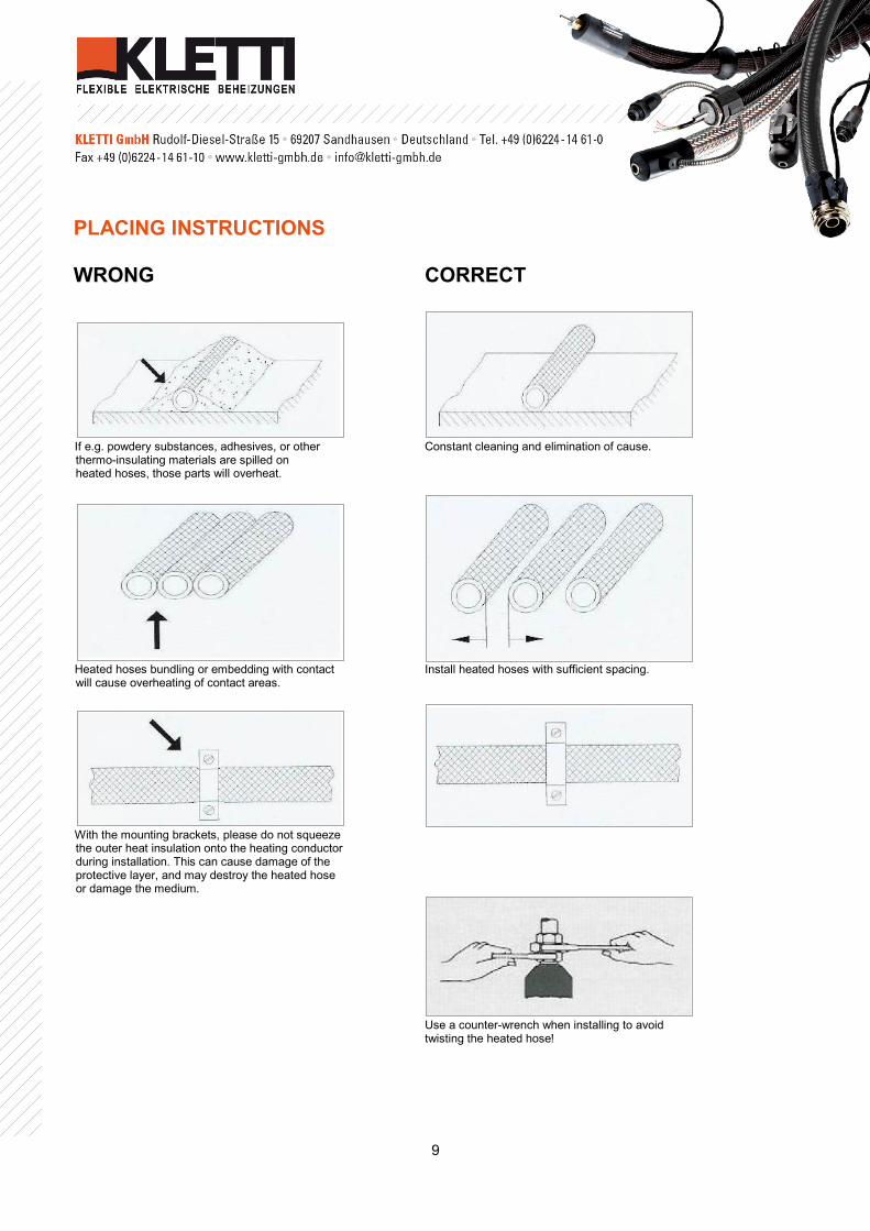
PLACING INSTRUCTIONS WRONG CORRECT
If e.g. powdery substances, adhesives, or other Constant cleaning and elimination of cause. thermo-insulating materials are spilled on heated hoses, those parts will overheat.
Heated hoses bundling or embedding with contact Install heated hoses with sufficient spacing. will cause overheating of contact areas.
With the mounting brackets, please do not squeeze the outer heat insulation onto the heating conductor during installation. This can cause damage of the protective layer, and may destroy the heated hose or damage the medium.
Use a counter-wrench when installing to avoid
twisting the heated hose!

10
Note on Fittings The fittings size depends on the nominal width of the hose DN (NW).Please observe that the inner diameter of the fitting is not identical with the nominal width of the hose and therefore restricts the hose passage. nominal diameter DN (NW) of the PTFE core
4 6 8 10 12 16 20 25 32 40
inner Diameter Fitting in mm
3,0 4,5 6,0 7,5 10,0 12,5 16,0 20,1 27,5 31,5
Maintenance and Repair Perform maintenance and repair according to the standards and conditions specified under the point "Safety precautions" observing all applicable regulations of the employer's liability insurance association and other conditions applicable for the type of application. The heating equipment and control should be checked for proper function at least once a year and testing intervals observed according to BGV A2. Technical data / Tolerances See type plate on the heating hose Electrical tolerance of performance + 5 % / - 10 % Length tolerance + / - 2 % Warranty We assume a warranty for
» our articles to be appropriately designed for a period of 12 months usage in single-shift operation* from their shipping date, to the extent that we will deliver ex-works Sandhausen free-of-charge replacements for all parts found to be prematurely defective due to design, workmanship or material faults when such defective items are freight-paid returned to Sandhausen. We are not liable for damage due to natural wear or improper handling. The guarantee period shall be reduced to 6 months for 2-shift operation or reduced to 4 months for 3- shift operation. » hoses of any type when proven to be a material defect. A fixed-period for guarantee is excluded since the durability is essentially dependent on handling care, i.e. from factors which are not under our control.
In no case shall liability be accepted for damage beyond the free-of-charge replacement of defective parts. This applies equally to other claims for damage, i.e. compensation for outlays of wages, freight and the like are expressly refused.

11
APPENDIX Handling of heated hoses when used for industrial robots The heated hoses for industrial robots are characterised by their special design. Due to the heavy dynamic load caused by the robot, the hose is equipped with a special outer sheath and a protective element for the inner temperature sensor in addition to various other specific measures.
Figure 1 Figure 2 Please make sure that the heated hose has a contact surface which is as large as possible and that it is attached to the robot with special hose protection elements (see figures 1 and 2). Do not use any cable ties to this end. Important: » It is of paramount importance not to undercut the specified bending radius of the heated hose. » For specific applications which demand a bending radius which is close to the limit and/or for excessively dynamic movements of the industrial robot, the heated hoses must be protected with hose protection springs or the like (see figures 3 and 4). » In the area of the temperature sensor the movement must be kept as low as possible. » In addition, you must make sure that the heated hose is neither compressed, twisted nor overstretched. » Furthermore you must pay attention to the fact that the heated hose is not pulled over any sharp edges or that it is not constantly subject to abrasion e.g. at a robot arm.
Figure 3 Figure 4 The more frequently a heated hose executes a movement per minute, the more important is the ideal choice of the outer sheath and its attachment to the robot. The service life of the heated hose (multi-shift operation) is the shorter, the more movements the hose is subject to per day (for this also see p.10 warranty).

12
Instructions for exchanging replaceable inner cores » Please loosen the hexagon socket set screw (Ø 2.5mm) on both sides of the hose. » Unscrew the double nipple. » Now you can remove the inner hose from the support sleeve. Pull out the inner hose on the side of the pressed-in fitting. » The installation of the new inner hose is effected in reverse order of the disassembly Manual addendum for the installation, implementation and operating of heating tubes within the hazardous area Depending on their individual construction, prototype-tested, explosion-proof heating conductors or selflimiting heating bands are processed as “radiators”. Please ensure that for this type of equipment the corresponding certificate by an accredited checkpoint is on hand. The test number indicated on these certificates must be concordant with the imprint on the label of the corresponding equipment. Regarding the installation site, please consider that the heating is only appropriate for the permissible hazardous area and the permissible ambient air temperature. The heating tubes might reach temperatures above the permissible temperature level according to the temperature classification and thus may only be operated in combination with a thermostat delimiter. In case of the regulated heating tubes equipped with heating conductors, two PT-100 thermostats are used as standard, which can only be operated through intrinsically safe sensor-entries at the corresponding thermostat-delimiter combinations. The heating tube may only be installed with a thermostat-delimiter permissible for the corresponding hazardous area. In case the combination is installed outside the hazardous area, it only has to be equipped with intrinsically safe sensor-entries. Before the heat tube system can be put into operation, a start-up test according to § 14 of BetrSichV (industrial safety regulations) has to be conducted. This has to be differentiated from testing the whole plant according to BetrSichV, addendum 4 (3.2). Apart from the general regulations indicated in the user manual, regulations for the installation of electric systems within an explosive area also apply. The EN 60519-1 “Safety in electro heat installations Part 1: General requirements“as well as the EN 60519-2 “Safety in electro heat installations Part 2: Particular requirements for resistance heating equipment.” The operator has to carefully ensure the following:
» The permissible temperature and the permissible pressure must not be exceeded. » he thermostat-delimiter-combination has to be selected and tested in correspondence with their installation within the hazardous area. » The earthing measures of the heating tube have to be conducted and tested before its activation. » The heating tube has to be included in the local potential equalisation. » A ground fault circuit interrupter for 30 mA is provided for.

13
HOSE ACCESSORIES For connecting, placing and guiding of heated hoses KLETTI offers the corresponding hose accessories.
Coil ring with holding device Gripping clamps Article no.: 40001 Article no.: 40005 Also suitable for heated hoses with polyamide braid.*
Trumpet Jointed tubing Article no.: 40002 Article no.: 40003 (available from NW48)
Middle-and end jaws Conduit protector Article no.: 40004 Article no.: 40000 (NW36)

14
ELECTRONIC TEMPERATURE CONTROL Serves for optimum temperature monitoring of the heating hoses. Whether temperature maintenance or temperature increases, our control products satisfy high demands for control of heating equipment for machines, systems and processes. All of our electronic, micro-processor controlled temperature regulators have the following features:
» stable table and wall housing with transparent cover » control and limiter system ready to plug in » two displays for indication of nominal and actual value » operation with function buttons » adjustment at parameter level » sensor input : Pt-100 or thermocouple » PID auto optimization » freely adjustable temperature range 0-1200°C » switching capacities up to 16 A possible
Series KM-RD2000 Series KM-RD1000 digital temperature regulator digital double temperature regulator
Series KM-RD3000 Series KM-RD4011 temperature regulator and delimiter temperature regulator and delimiter combination combination Ex-design

15
QUALITY MANAGEMENT Safety, Quality and costumer satisfaction are our main goals: » Certification TÜV DIN ISO 9001 : 2000 » From now on you can get some heated hoses from KLETTI with UL / CAS registration based on the security testing our products for the markets of the USA and Canada. » Anti-explosion certification for temperature category T3 in explosive areas in zones 1, 2 (gas) and 21, 22 (dust).
CONTACT KLETTI GmbH Rudolf Diesel Str.15 69207 Sandhausen Germany Tel. +49 (0)6224 – 1461-0 Fax +49 (0)6224 – 1461-10 [email protected] www.kletti-gmbh.de