Embed Size (px)
Citation preview

ENGINEERING TOMORROW
Operating GuideVLT® AQUA Drive FC 202355–800 kW, Enclosure Sizes E1h–E4h
vlt-drives.danfoss.com


Contents
1 Introduction 3
1.1 Purpose of the Manual 3
1.2 Additional Resources 3
1.3 Manual and Software Version 3
1.4 Approvals and Certifications 3
1.5 Disposal 3
2 Safety 4
2.1 Safety Symbols 4
2.2 Qualified Personnel 4
2.3 Safety Precautions 4
3 Product Overview 6
3.1 Intended Use 6
3.2 Power Ratings, Weights, and Dimensions 6
3.3 Interior View of Enclosures E1h and E2h 7
3.4 Interior View of Enclosures E3h and E4h 8
3.5 Control Shelf 9
3.6 Local Control Panel (LCP) 10
4 Mechanical Installation 12
4.1 Items Supplied 12
4.2 Tools Needed 12
4.3 Storage 12
4.4 Operating Environment 13
4.5 Installation and Cooling Requirements 14
4.6 Lifting the Unit 14
4.7 E1h/E2h Mechanical Installation 15
4.8 E3h/E4h Mechanical Installation 17
5 Electrical Installation 20
5.1 Safety Instructions 20
5.2 EMC-compliant Installation 20
5.3 Wiring Schematic 23
5.4 Connecting the Motor 24
5.5 Connecting the AC Mains 26
5.6 Connecting to Ground 28
5.7 Terminal Dimensions 30
5.8 Control Wiring 40
5.9 Pre-start Check List 45
Contents Operating Guide
MG22A202 Danfoss A/S © 04/2018 All rights reserved. 1

6 Commissioning 46
6.1 Safety Instructions 46
6.2 Applying Power 46
6.3 LCP Menu 47
6.4 Programming the Drive 48
6.5 Testing Before System Start-up 51
6.6 System Start-up 51
6.7 Parameter Settings 52
7 Wiring Configuration Examples 54
7.1 Wiring for Open-loop Speed Control 54
7.2 Wiring for Start/Stop 55
7.3 Wiring for External Alarm Reset 56
7.4 Wiring for a Motor Thermistor 57
7.5 Wiring for Regeneration 57
8 Maintenance, Diagnostics, and Troubleshooting 58
8.1 Maintenance and Service 58
8.2 Heat Sink Access Panel 58
8.3 Status Messages 59
8.4 Warning and Alarm Types 61
8.5 List of Warnings and Alarms 62
8.6 Troubleshooting 71
9 Specifications 73
9.1 Electrical Data 73
9.2 Mains Supply 78
9.3 Motor Output and Motor Data 78
9.4 Ambient Conditions 78
9.5 Cable Specifications 79
9.6 Control Input/Output and Control Data 79
9.7 Fuses 82
9.8 Enclosure Dimensions 83
9.9 Enclosure Airflow 99
9.10 Fastener Torque Ratings 100
10 Appendix 101
10.1 Abbreviations and Conventions 101
10.2 International/North American Default Parameter Settings 102
10.3 Parameter Menu Structure 102
Index 108
Contents VLT® AQUA Drive FC 202
2 Danfoss A/S © 04/2018 All rights reserved. MG22A202

1 Introduction
1.1 Purpose of the Manual
This operating guide provides information for safe instal-lation and commissioning of the VLT® drives in anenclosure size E (E1h, E2h, E3h, and E4h).
The operating guide is intended for use by qualifiedpersonnel. To use the unit safely and professionally, readand follow this operating guide. Pay particular attention tothe safety instructions and general warnings. Always keepthe operating guide with the drive.
VLT® is a registered trademark.
1.2 Additional Resources
Other resources are available to understand advanced E1h–E4h drive functions and programming.
• The VLT® AQUA Drive FC 202 Programming Guideprovides greater detail on working withparameters and aqua application examples.
• The VLT® AQUA Drive FC 202, 110–1400 kW DesignGuide provides detailed capabilities andfunctionality to design motor control systems foraqua applications.
• The Safe Torque Off Operating Guide.
Supplementary publications and manuals are availablefrom Danfoss. See www.danfoss.com/en/search/?filter=type%3Adocumentation for listings.
1.3 Manual and Software Version
This manual is regularly reviewed and updated. Allsuggestions for improvement are welcome. Table 1.1 showsthe version of the manual and the corresponding softwareversion.
Manual version Remarks Softwareversion
MG22A2xx Added output contactorwarning and other corrections.
2.70
Table 1.1 Manual and Software Version
1.4 Approvals and Certifications
Table 1.2 Approvals and Certifications
More approvals and certifications are available. Contact thelocal Danfoss office or partner. Drives of voltage T7 (525–690 V) are UL certified for only 525–690 V.
The drive complies with UL 61800-5-1 thermal memoryretention requirements. For more information, refer to thesection Motor Thermal Protection in the product-specificdesign guide.
NOTICEIMPOSED LIMITATIONS ON THE OUTPUTFREQUENCYFrom software version 1.99, the output frequency of thedrive is limited to 590 Hz due to export controlregulations.
1.4.1 Compliance with ADN
For compliance with the European Agreement concerningInternational Carriage of Dangerous Goods by InlandWaterways (ADN), refer to ADN-compliant Installation in thedesign guide.
1.5 Disposal
Do not dispose of equipment containingelectrical components together withdomestic waste.Collect it separately in accordance withlocal and currently valid legislation.
Introduction Operating Guide
MG22A202 Danfoss A/S © 04/2018 All rights reserved. 3
1 1

2 Safety
2.1 Safety Symbols
The following symbols are used in this guide:
WARNINGIndicates a potentially hazardous situation that couldresult in death or serious injury.
CAUTIONIndicates a potentially hazardous situation that couldresult in minor or moderate injury. It can also be used toalert against unsafe practices.
NOTICEIndicates important information, including situations thatcan result in damage to equipment or property.
2.2 Qualified Personnel
Correct and reliable transport, storage, installation,operation, and maintenance are required for the trouble-free and safe operation of the drive. Only qualifiedpersonnel are allowed to install or operate this equipment.
Qualified personnel are defined as trained staff, who areauthorized to install, commission, and maintain equipment,systems, and circuits in accordance with pertinent laws andregulations. Also, the personnel must be familiar with theinstructions and safety measures described in this manual.
2.3 Safety Precautions
WARNINGHIGH VOLTAGEDrives contain high voltage when connected to AC mainsinput, DC supply, load sharing, or permanent motors.Failure to use qualified personnel to install, start up, andmaintain the drive can result in death or serious injury.
• Only qualified personnel must install, start up,and maintain the drive.
WARNINGUNINTENDED STARTWhen the drive is connected to the AC mains, DC supply,or load sharing, the motor can start at any time.Unintended start during programming, service, or repairwork can result in death, serious injury, or propertydamage. The motor can start with an external switch, afieldbus command, an input reference signal from theLCP or LOP, via remote operation using MCT 10 Set-upSoftware, or after a cleared fault condition.
To prevent unintended motor start:• Press [Off/Reset] on the LCP before
programming parameters.
• Disconnect the drive from the mains.
• Completely wire and assemble the drive, motor,and any driven equipment before connectingthe drive to the AC mains, DC supply, or loadsharing.
WARNINGDISCHARGE TIMEThe drive contains DC-link capacitors, which can remaincharged even when the drive is not powered. Highvoltage can be present even when the warning LEDindicator lights are off. Failure to wait 40 minutes afterpower has been removed before performing service orrepair work can result in death or serious injury.
1. Stop the motor.
2. Disconnect AC mains and remote DC-linksupplies, including battery back-ups, UPS, andDC-link connections to other drives.
3. Disconnect or lock motor.
4. Wait 40 minutes for the capacitors to dischargefully.
5. Before performing any service or repair work,use an appropriate voltage measuring device tomake sure that the capacitors are fullydischarged.
WARNINGLEAKAGE CURRENT HAZARDLeakage currents exceed 3.5 mA. Failure to ground thedrive properly can result in death or serious injury.
• Ensure the correct grounding of the equipmentby a certified electrical installer.
Safety VLT® AQUA Drive FC 202
4 Danfoss A/S © 04/2018 All rights reserved. MG22A202
22

WARNINGEQUIPMENT HAZARDContact with rotating shafts and electrical equipmentcan result in death or serious injury.
• Ensure that only trained and qualified personnelinstall, start up, and maintain the drive.
• Ensure that electrical work conforms to nationaland local electrical codes.
• Follow the procedures in this guide.
CAUTIONHOT SURFACESThe drive contains metal components that are still hoteven after the drive has been powered off. Failure toobserve the high temperature symbol (yellow triangle)on the drive can result in serious burns.
• Be aware that internal components, such asbusbars, may be extremely hot even after thedrive has been powered off.
• Exterior areas marked by the high temperaturesymbol (yellow triangle) are hot while the driveis in use and immediately after being poweredoff.
WARNINGINTERNAL FAILURE HAZARDUnder certain circumstances, an internal failure cancause a component to explode. Failure to keep theenclosure closed and properly secured can cause deathor serious injury.
• Do not operate the drive with the door open orpanels off.
• Ensure that the enclosure is properly closed andsecured during operation.
NOTICEMAINS SHIELD SAFETY OPTIONA mains shield option is available for enclosures with aprotection rating of IP21/IP54 (Type 1/Type 12). Themains shield is a cover installed inside the enclosure toprotect against the accidental touch of the powerterminals, according to BGV A2, VBG 4.
Safety Operating Guide
MG22A202 Danfoss A/S © 04/2018 All rights reserved. 5
2 2

3 Product Overview
3.1 Intended Use
The drive is an electronic motor controller that converts AC mains input into a variable AC waveform output. The frequencyand voltage of the output are regulated to control the motor speed or torque. The drive is designed to:
• Regulate motor speed in response to system feedback or to remote commands from external controllers.
• Monitor system and motor status.
• Provide motor overload protection.
The drive is designed for industrial and commercial environments in accordance with local laws and standards. Dependingon configuration, the drive can be used in standalone applications or form part of a larger system or installation.
NOTICEIn a residential environment, this product can cause radio interference, in which case supplementary mitigationmeasures can be required.
Foreseeable misuseDo not use the drive in applications which are non-compliant with specified operating conditions and environments. Ensurecompliance with the conditions specified in chapter 9 Specifications.
3.2 Power Ratings, Weights, and Dimensions
Table 3.1 provides dimensions for standard configurations. For dimensions on optional configurations, seechapter 9.8 Enclosure Dimensions.
Enclosure size E1h E2h E3h E4h
Rated power at 380–480 V [kW (hp)] 355–450(500–600)
500–560(650–750)
355–450(500–600)
500–560(650–750)
Rated power at 525–690 V [kW (hp)] 450–630(450–650)
710–800(750–950)
450–630(450–650)
710–800(750–950)
Enclosure protection rating IP21/Type 1IP54/Type 12
IP21/Type 1IP54/Type 12
IP20/Chassis
IP20/Chassis
Unit dimensions
Height [mm (in)] 2043 (80.4) 2043 (80.4) 1578 (62.1) 1578 (62.1)
Width [mm (in)] 602 (23.7) 698 (27.5) 506 (19.9) 604 (23.89)
Depth [mm (in)] 513 (20.2) 513 (20.2) 482 (19.0) 482 (19.0)
Weight [kg (lb)] 295 (650) 318 (700) 272 (600) 295 (650)
Shipping dimensions
Height [mm (in)] 2191 (86.3) 2191 (86.3) 1759 (69.3) 1759 (69.3)
Width [mm (in)] 768 (30.2) 768 (30.2) 746 (29.4) 746 (29.4)
Depth [mm (in)] 870 (34.3) 870 (34.3) 794 (31.3) 794 (31.3)
Weight [kg (lb)] – – – –
Table 3.1 Enclosure Power Ratings and Dimensions
Product Overview VLT® AQUA Drive FC 202
6 Danfoss A/S © 04/2018 All rights reserved. MG22A202
33

3.3 Interior View of Enclosures E1h and E2h
130B
F206
.11
FASTENER TORQUE:M10 19Nm (14FT-LB)M12 35Nm (26FT-LB)
- REGEN 83FASTENER TORQUE:M10 19Nm (14FT-LB)M12 35Nm (26FT-LB)
+ REGEN 82
2
6
4
5 11
12
9
1
7
10
83
1 Control shelf (see Illustration 3.3) 7 Fan power card
2 Local control panel (LCP) cradle 8 Space heater (optional)
3 RFI filter (optional) 9 Mains disconnect (optional)
4 Mains fuses (required for UL compliance, but otherwiseoptional)
10 Brake/regeneration terminals (optional)
5 Mains terminals 11 Motor terminals
6 RFI shield termination 12 Ground terminals
Illustration 3.1 Interior View of Enclosure E1h (Enclosure E2h is Similar)
Product Overview Operating Guide
MG22A202 Danfoss A/S © 04/2018 All rights reserved. 7
3 3

3.4 Interior View of Enclosures E3h and E4h
FASTENER TORQUE:M10 19Nm (14FT-LB)M12 35Nm (26FT-LB)
+ DC 89
FASTENER TORQUE:M10 19Nm (14FT-LB)M12 35Nm (26FT-LB)
- BRAKE 83FASTENER TORQUE:M10 19Nm (14FT-LB)M12 35Nm (26FT-LB)
+ BRAKE 82
FASTENER TORQUE:M10 19Nm (14FT-LB)M12 35Nm (26FT-LB)
- DC 88
130B
F211
.11
1
6
2
5
9
12
13
11
7
8
3 10
4
1 Load share/regeneration terminals (optional) 8 RFI shield termination (optional, but is standard when RFIfilter is ordered)
2 Control shelf (see Illustration 3.3) 9 Fans (used to cool the front section of enclosure)
3 Local control panel (LCP) cradle 10 Fan power card
4 RFI filter (optional) 11 Space heater (optional)
5 Mains fuses (optional) 12 Brake terminals (optional)
6 Mains terminals 13 Motor terminals
7 Ground terminals – –
Illustration 3.2 Interior View of Enclosure E3h (Enclosure E4h is Similar)
Product Overview VLT® AQUA Drive FC 202
8 Danfoss A/S © 04/2018 All rights reserved. MG22A202
33
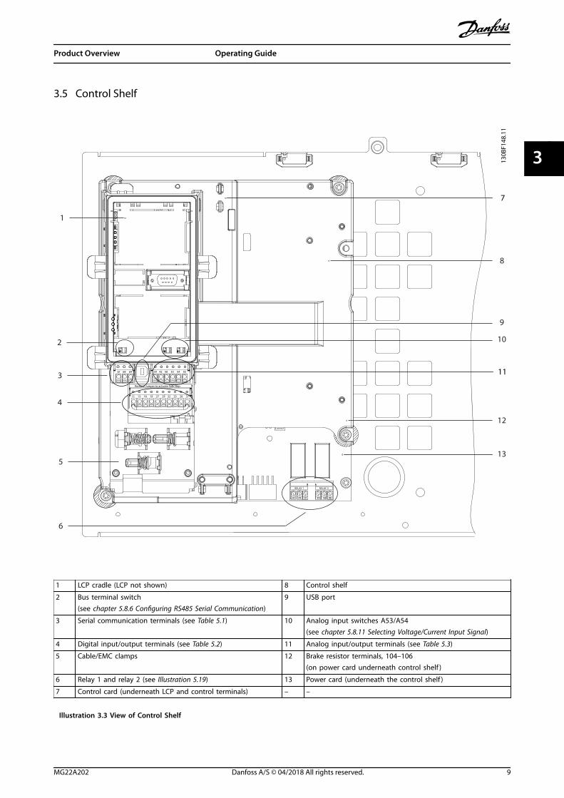
3.5 Control Shelf
130B
F148
.11
Remove Jumper to activate Safe Stop
12 13 18 19 27 29 32 33 20 37
39 42 50 53 54 55 61 68 69
1
3
4
12
9
8
RELAY 1 RELAY 2
01 02 03 04 05 06
2
6
10
7
5
11
13
1 LCP cradle (LCP not shown) 8 Control shelf
2 Bus terminal switch(see chapter 5.8.6 Configuring RS485 Serial Communication)
9 USB port
3 Serial communication terminals (see Table 5.1) 10 Analog input switches A53/A54(see chapter 5.8.11 Selecting Voltage/Current Input Signal)
4 Digital input/output terminals (see Table 5.2) 11 Analog input/output terminals (see Table 5.3)
5 Cable/EMC clamps 12 Brake resistor terminals, 104–106(on power card underneath control shelf )
6 Relay 1 and relay 2 (see Illustration 5.19) 13 Power card (underneath the control shelf )
7 Control card (underneath LCP and control terminals) – –
Illustration 3.3 View of Control Shelf
Product Overview Operating Guide
MG22A202 Danfoss A/S © 04/2018 All rights reserved. 9
3 3

3.6 Local Control Panel (LCP)
The local control panel (LCP) is the combined display and keypad on the front of the drive.
The LCP is used to:
• Control the drive and motor.
• Access drive parameters and program the drive.
• Display operational data, drive status, and warnings.
A numeric local control panel (NLCP) is available as an option. The NLCP operates in a manner similar to the LCP, but thereare differences. For details on how to use the NLCP, see the product-specific programming guide.
130B
F154
.11
AutoOn
ResetHandOn
Off
StatusQuickMenu
MainMenu
AlarmLog
BackCancel
InfoOK
Status 1(1)
0.00 A
Off Remote Stop
0.0 Hz
On
Alarm
Warn.
0.0000.000 RPM
0.0000
A1.1
A1.2
A1.3
A2
A3
B1
B2
B4
B3
C1
C2
C3
C4C5
D1
D2
D3
E1
E2
E3
E4
Illustration 3.4 Graphical Local Control Panel (LCP)
A. Display areaEach display readout has a parameter associated with it. See Table 3.2. The information shown on the LCP can becustomized for specific applications. Refer to chapter 6.3.1.2 Q1 My Personal Menu.
Callout Parameter number Default setting
A1.1 0-20 Reference [Unit]
A1.2 0-21 Analog input 53 [V]
A1.3 0-22 Motor current [A]
A2 0-23 Frequency [Hz]
A3 0-24 Feedback [Unit]
Table 3.2 LCP Display Area
Product Overview VLT® AQUA Drive FC 202
10 Danfoss A/S © 04/2018 All rights reserved. MG22A202
33

B. Menu keysMenu keys are used to access the menu for setting upparameters, toggling through status display modes duringnormal operation, and viewing fault log data.
Callout Key Function
B1 Status Shows operational information.
B2 Quick Menu Allows access to parameters for initialset-up instructions. Also providesdetailed application steps. Referto chapter 6.3.1.1 Quick Menu Mode.
B3 Main Menu Allows access to all parameters. Refer tochapter 6.3.1.9 Main Menu Mode.
B4 Alarm Log Shows a list of current warnings and thelast 10 alarms.
Table 3.3 LCP Menu Keys
C. Navigation keysNavigation keys are used for programming functions andmoving the display cursor. The navigation keys alsoprovide speed control in local (hand) operation. Thedisplay brightness can be adjusted by pressing [Status] and[]/[] keys.
Callout Key Function
C1 Back Reverts to the previous step or list in themenu structure.
C2 Cancel Cancels the last change or command aslong as the display mode has not changed.
C3 Info Shows a definition of the function beingshown.
C4 OK Accesses parameter groups or enables anoption.
C5 Moves between items in the menu.
Table 3.4 LCP Navigation Keys
D. Indicator lightsIndicator lights are used to identify the drive status and toprovide a visual notification of warning or fault conditions.
Callout Indicator Indicatorlight
Function
D1 On Green Activates when the drive receivespower from the mains voltage ora 24 V external supply.
D2 Warn. Yellow Activates when warningconditions are active. Textappears in the display areaidentifying the problem.
D3 Alarm Red Activates during a faultcondition. Text appears in thedisplay area identifying theproblem.
Table 3.5 LCP Indicator Lights
E. Operation keys and resetThe operation keys are found toward the bottom of thelocal control panel.
Callout Key Function
E1 Hand on Starts the drive in local control. Anexternal stop signal by control input orserial communication overrides the local[Hand On].
E2 Off Stops the motor but does not removepower to the drive.
E3 Auto on Puts the system in remote operationalmode so it can respond to an externalstart command by control terminals orserial communication.
E4 Reset Resets the drive manually after a fault hasbeen cleared.
Table 3.6 LCP Operation Keys and Reset
Product Overview Operating Guide
MG22A202 Danfoss A/S © 04/2018 All rights reserved. 11
3 3

4 Mechanical Installation
4.1 Items Supplied
Items supplied can vary according to product configu-ration.
• Make sure that the items supplied and theinformation on the nameplate correspond to theorder confirmation.
• Visually check the packaging and the drive fordamage caused by inappropriate handling duringshipment. File any claim for damage with thecarrier. Retain damaged parts for clarification.
Tamb. 55 C/131 F at Full Output Current Derating
IN: 3x525-600V 50/60Hz 743/711 A (UL)OUT: MOTOR 3x0-Vin 0-500Hz 763/730 A
IN: 3x525-690V 50/60Hz 743/711 A (CE)710 kW / 750 HP, High Overload
OUT: MOTOR 3x0-Vin 0-500Hz 889/850 A
IN: 3x525-690V 50/60Hz 866/828 A (CE)800 kW / 950 HP, Normal Overload
VLTT/C: FC-202N710T7E21H2XGC7XKSXXXXA0BXCXXXXD0P/N: 131N2885 S/N:
R AQUA Drivewww.danfoss.com
130B
F712
.11
IN: 3x525-690V 50/60Hz 866/828 A (UL)
ASSEMBLED IN USA
Tamb. 45 C/113 F at Full Output Current IP21 / TYPE 1
SCCR 100 kA at UL Voltage range 525-600 V
Listed 36U0 E70524 IND. CONT. EQ.UL Voltage range 525-600 V
CAUTION - ATTENTION:
Stored charge, wait 40 min.Charge residuelle, attendez 40 min.
See manual for special condition / prefusesVoir manuel de conditions speciales / fusibles
WARNING - AVERTISSEMENT:`
`
123456H12312345
6
Danfoss A/S6430 NordborgDenmark
1 Type code
2 Code number
3 Power rating
4Input voltage, frequency, and current (at low/highvoltages)
5Output voltage, frequency, and current (at low/highvoltages)
6 Discharge time
Illustration 4.1 Product Nameplate for E2h Enclosure (Example)
NOTICERemoving the nameplate from the drive can result in theloss of warranty.
4.2 Tools Needed
Receiving/unloading
• I-beam and hooks rated to lift the weight of thedrive. Refer to chapter 3.2 Power Ratings, Weights,and Dimensions.
• Crane or other lifting aid to place the unit intoposition.
Installation
• Drill with 10 mm or 12 mm drill bits.
• Tape measurer.
• Various sizes of Phillips and flat bladedscrewdrivers.
• Wrench with relevant metric sockets (7–17 mm).
• Wrench extensions.
• Torx drives (T25 and T50).
• Sheet metal punch for conduits or cable glands.
• I-beam and hooks to lift the weight of the drive.Refer to chapter 3.2 Power Ratings, Weights, andDimensions.
• Crane or other lifting aid to place the drive ontopedestal and into position.
4.3 Storage
Store the drive in a dry location. Keep the equipmentsealed in its packaging until installation. Refer to chapter 9.4 Ambient Conditions for recommended ambienttemperature.
Periodic forming (capacitor charging) is not necessaryduring storage unless storage exceeds 12 months.
Mechanical Installation VLT® AQUA Drive FC 202
12 Danfoss A/S © 04/2018 All rights reserved. MG22A202
44

4.4 Operating Environment
In environments with airborne liquids, particles, orcorrosive gases, ensure that the IP/Type rating of theequipment matches the installation environment. Forspecifications regarding ambient conditions, seechapter 9.4 Ambient Conditions.
NOTICECONDENSATIONMoisture can condense on the electronic componentsand cause short circuits. Avoid installation in areassubject to frost. Install an optional space heater whenthe drive is colder than the ambient air. Operating instandby mode reduces the risk of condensation as longas the power dissipation keeps the circuitry free ofmoisture.
NOTICEEXTREME AMBIENT CONDITIONSHot or cold temperatures compromise unit performanceand longevity.
• Do not operate in environments where theambient temperature exceeds 55 °C (131 °F).
• The drive can operate at temperatures down to-10 °C (14 °F). However, proper operation atrated load is only guaranteed at 0 °C (32 °F) orhigher.
• If temperature exceeds ambient temperaturelimits, extra air conditioning of the cabinet orinstallation site is required.
4.4.1 Gases
Aggressive gases, such as hydrogen sulfide, chlorine, orammonia can damage the electrical and mechanicalcomponents. The unit uses conformal-coated circuit boardsto reduce the effects of aggressive gases. For conformal-coating class specifications and ratings, see chapter 9.4 Ambient Conditions.
4.4.2 Dust
When installing the drive in dusty environments, payattention to the following:
Periodic maintenanceWhen dust accumulates on electronic components, it actsas a layer of insulation. This layer reduces the coolingcapacity of the components, and the components becomewarmer. The hotter environment decreases the life of theelectronic components.
Keep the heat sink and fans free from dust buildup. Formore service and maintenance information, refer to chapter 8 Maintenance, Diagnostics, and Troubleshooting.
Cooling fansFans provide airflow to cool the drive. When fans areexposed to dusty environments, the dust can damage thefan bearings and cause premature fan failure. Also, dustcan accumulate on fan blades causing an imbalance whichprevents the fans from properly cooling the unit.
4.4.3 Potentially Explosive Atmospheres
WARNINGEXPLOSIVE ATMOSPHEREDo not install the drive in a potentially explosiveatmosphere. Install the unit in a cabinet outside of thisarea. Failure to follow this guideline increases risk ofdeath or serious injury.
Systems operated in potentially explosive atmospheresmust fulfill special conditions. EU Directive 94/9/EC(ATEX 95) classifies the operation of electronic devices inpotentially explosive atmospheres.
• Class d specifies that if a spark occurs, it iscontained in a protected area.
• Class e prohibits any occurrence of a spark.
Motors with class d protectionDoes not require approval. Special wiring and containmentare required.
Motors with class e protectionWhen combined with an ATEX approved PTC monitoringdevice like the VLT® PTC Thermistor Card MCB 112, instal-lation does not need an individual approval from anapprobated organization.
Motors with class d/e protectionThe motor itself has an e ignition protection class, whilethe motor cabling and connection environment is incompliance with the d classification. To attenuate the highpeak voltage, use a sine-wave filter at the drive output.
When using a drive in a potentially explosiveatmosphere, use the following:
• Motors with ignition protection class d or e.
• PTC temperature sensor to monitor the motortemperature.
• Short motor cables.
• Sine-wave output filters when shielded motorcables are not used.
Mechanical Installation Operating Guide
MG22A202 Danfoss A/S © 04/2018 All rights reserved. 13
4 4

NOTICEMOTOR THERMISTOR SENSOR MONITORINGDrives with the VLT® PTC Thermistor Card MCB 112option are PTB-certified for potentially explosiveatmospheres.
4.5 Installation and Cooling Requirements
NOTICEImproper mounting can result in overheating andreduced performance.
Installation requirements
• Locate the unit as near to the motor as possible.See chapter 9.5 Cable Specifications for themaximum motor cable length.
• Ensure unit stability by mounting the unit to asolid surface.
• Enclosures E3h and E4h can be mounted:
- Vertically on the back plate of the panel(typical installation).
- Vertically upside down on the backplate of the panel.1)
- Horizontally on its back, mounted onthe back plate of the panel.1)
- Horizontally on its side, mounted onfloor of the panel.1)
• Ensure that the strength of the mounting locationsupports the unit weight.
• Ensure that there is enough space around theunit for proper cooling. Refer tochapter 9.9 Enclosure Airflow.
• Ensure enough access to open the door.
• Ensure cable entry from the bottom.
1) For non-typical installation, contact the factory.
Cooling requirements• Ensure that top and bottom clearance for air
cooling is provided. Clearance requirement:225 mm (9 in).
• Provide sufficient airflow flow rate. See Table 4.1.
• Consider derating for temperatures startingbetween 45 °C (113 °F) and 50 °C (122 °F) andelevation 1000 m (3300 ft) above sea level. Seethe design guide for detailed information.
The drive utilizes a back-channel cooling concept thatremoves heat sink cooling air. The heat sink cooling aircarries approximately 90% of the heat out of the backchannel of the drive. Redirect the back-channel air fromthe panel or room by using:
• Duct coolingBack-channel cooling kits are available to directthe heat sink cooling air out of the panel whenIP20/Chassis drives are installed in Rittalenclosures. These kits reduce the heat in thepanel and smaller door fans can be specified.
• Back-wall coolingInstalling top and base covers to the unit allowsthe back-channel cooling air to be ventilated outof the room.
NOTICEFor E3h and E4h enclosures (IP20/Chassis), at least 1door fan is required on the enclosure to remove the heatnot contained in the back-channel of the drive. It alsoremoves any additional losses generated by othercomponents inside the drive. To select the appropriatefan size, calculate the total required airflow.
Secure the necessary airflow over the heat sink.
Frame Door fan/top fan
[m3/hr (cfm)]
Heat sink fan
[m3/hr (cfm)]
E1h51h 510 (300) 994 (585)
E2h 552 (325) 1053–1206 (620–710)
E3h 595 (350) 994 (585)
E4h 629 (370) 1053–1206 (620–710)
Table 4.1 Airflow Rate
4.6 Lifting the Unit
Always lift the drive using the dedicated lifting eyes. Toavoid bending the lifting holes, use a bar.
WARNINGRISK OF INJURY OR DEATHFollow local safety regulations for lifting heavy weights.Failure to follow recommendations and local safetyregulations can result in death or serious injury.
• Ensure that the lifting equipment is in properworking condition.
• See chapter 3.2 Power Ratings, Weights, andDimensions for the weight of the differentenclosure sizes.
• Maximum diameter for bar: 20 mm (0.8 in).
• The angle from the top of the drive to thelifting cable: 60° or greater.
Mechanical Installation VLT® AQUA Drive FC 202
14 Danfoss A/S © 04/2018 All rights reserved. MG22A202
44

130B
F685
.10
Illustration 4.2 Recommended Lifting Method
4.7 E1h/E2h Mechanical Installation
The E1h and E2h enclosure size is intended only for floorinstallation, and is shipped with a pedestal and a glandplate. The pedestal and gland plate must be installed forproper installation.
The pedestal is 200 mm (7.9 in) and has an opening in thefront to allow airflow necessary to cool the powercomponents of the drive.
The gland plate is necessary to provide cooling air to thecontrol components of the drive via the door fan, and tomaintain the IP21/Type 1 or IP54/Type 12 protection rating.
4.7.1 Securing the Pedestal to the Floor
The pedestal must be secured to the floor using 6 boltsbefore installing the enclosure.
1. Determine proper placement of the unit,concerning operating conditions and cableaccess.
2. Access the mounting holes by removing the frontpanel of the pedestal.
3. Set the pedestal on the floor and secure using 6bolts through the mounting holes. Refer to thecircled areas in Illustration 4.3.
130B
F208
.10
Illustration 4.3 Pedestal to Floor Mounting Points
4.7.2 Attaching the E1h/E2h to the Pedestal
1. Lift the drive and position it on the pedestal.There are 2 bolts in the rear of the pedestal thatslide into the 2 slotted holes in the rear of theenclosure. Position the drive by adjusting thebolts up or down. Loosely secure with 2 M10 nutsand locking brackets. See Illustration 4.4.
2. Verify that there is 225 mm (9 in) top clearancefor air exhaust.
3. Verify that the air intake at the bottom front ofthe unit is not obstructed.
4. Around the top of the pedestal, secure theenclosure using 6 M10x30 fasteners. Refer toIllustration 4.5. Loosely tighten each bolt until allbolts are installed.
5. Fasten each bolt securely and torque to 19 Nm(169 in-lb).
6. Torque the 2 M10 nuts at the rear of theenclosure to 19 Nm (169 in-lb).
Mechanical Installation Operating Guide
MG22A202 Danfoss A/S © 04/2018 All rights reserved. 15
4 4

130B
F225
.10
1
2
5
46
3
1 Enclosure 4 Slotted hole in enclosure
2 Pedestal 5 Bolt at rear of pedestal
3 M10 nut 6 Locking bracket
Illustration 4.4 Pedestal to Enclosure Back Mounting Points
130B
F207
.10
1
23
1 Enclosure 3 M10x30 fasteners(rear corner bolts notshown)
2 Pedestal – –
Illustration 4.5 Pedestal to Enclosure Mounting Points
4.7.3 Creating Cable Openings
The gland plate is a sheet of metal with studs along theouter edge. The gland plate provides cable entry and cabletermination points, and must be installed to maintain theIP21/IP54 (Type 1/Type 12) protection rating. The plate isplaced between the drive enclosure and the pedestal.Depending on stud orientation, the plate can be installedfrom inside the enclosure or the pedestal. For gland platedimensions, see chapter 9.8.1 E1h Exterior Dimensions.
Refer to Illustration 4.6 for the following steps.
1. Create cable entry holes in the gland plate usinga sheet metal punch.
2. Insert the gland plate using 1 of the followingmethods:
2a To insert the gland plate through thepedestal, slide the gland plate throughthe slot (4) in the front of the pedestal.
2b To insert the gland plate through theenclosure, angle the gland plate until itcan be slid under the slotted brackets.
3. Align the studs on the gland plate to the holes inthe pedestal and secure with 10 M5 nuts (2).
4. Torque each nut to 2.3 Nm (20 in-lb).
130B
F209
.10
1
3
4
2
1 Cable entry hole 4 Slot in pedestal base
2 M5 nut 5 Front cover/grill
3 Gland plate – –
Illustration 4.6 Installing the Gland Plate
Mechanical Installation VLT® AQUA Drive FC 202
16 Danfoss A/S © 04/2018 All rights reserved. MG22A202
44

4.8 E3h/E4h Mechanical Installation
The E3h and E4h enclosure sizes are intended to bemounted on a wall or on a mounting panel within anenclosure. A plastic gland plate is installed on theenclosure. It is designed to prevent unintentional access tothe terminals in an IP20/protected chasis unit.
NOTICEREGENERATION/LOAD SHARE OPTIONDue to the exposed terminals at the top of theenclosure, units with the regeneration/load share optionhave an IP00 protection rating.
4.8.1 Attaching the E3h/E4h to a MountingPlate or Wall
1. Drill the mounting holes according to theenclosure size. Refer to chapter 9.8 EnclosureDimensions.
2. Secure the top of the drive enclosure to themounting plate or wall.
3. Secure the base of the drive enclosure to themounting plate or wall.
4.8.2 Creating Cable Openings
The gland plate covers the bottom part of the driveenclosure and must be installed to maintain the IP20/Chassis protection rating. The gland plate consists ofplastic squares that can be cut out to provide cable accessto the terminals. See Illustration 4.7.
1. Remove the bottom panel and terminal cover.See Illustration 4.8.
1a Detach the bottom panel by removing 4T25 screws.
1b Remove 5 T20 screws that secure thebottom of the drive to the top of theterminal cover, and then pull theterminal cover straight out.
2. Determine the size and position of the motor,mains, and ground cables. Note their position andmeasurements.
3. Based on the measurement and positions of thecables, create openings in the plastic gland plateby cutting out the necessary squares.
4. Slide the plastic gland plate (7) onto the bottomrails of the terminal cover.
5. Tilt the front of the terminal cover downwarduntil the fastener points (8) rest on the slotteddrive brackets (6).
6. Make sure the side panels of the terminal coverare on the outside track guide (5).
7. Push the terminal cover until it is up against theslotted drive bracket.
8. Tilt the front of the terminal cover upward untilthe fastener hole in the bottom of the drivealigns with the keyhole opening (9) in theterminal. Secure with 2 T25 screws and torque to2.3 Nm (20 in-lb).
9. Secure the bottom panel with 3 T25 screws andtorque to 2.3 Nm (20 in-lb).
1
130B
F662
.10
2
1 Plastic square
2 Squares removed for cable access
Illustration 4.7 Plastic Gland Plate
Mechanical Installation Operating Guide
MG22A202 Danfoss A/S © 04/2018 All rights reserved. 17
4 4

6
7
9
5
8
413
0BF6
88.1
0
2
3
1
1 Load share/regeneration terminals (optional) 6 Slotted drive bracket
2 Bottom panel 7 Plastic gland plate (installed)
3 Terminal cover 8 Fastener point
4 Grommet access hole for control wiring 9 Keyhole opening
5 Track guide – –
Illustration 4.8 Assembling the Gland Plate and Terminal Cover
Mechanical Installation VLT® AQUA Drive FC 202
18 Danfoss A/S © 04/2018 All rights reserved. MG22A202
44

4.8.3 Installing Load share/Regeneration Terminals
The load share/regeneration terminals, located on the topof the drive, are not installed from the factory to preventdamage during shipping. Refer to Illustration 4.9 for thefollowing steps.
130B
F697
.10
3
5
4
1
2
1 Label fastener, M4
2 Label
3 Load share/regeneration terminal
4 Terminal fastener, M10
5 Terminal plate with 2 openings
Illustration 4.9 Load share/Regeneration Terminals
1. Remove the terminal plate, 2 terminals, label, andfasteners from the accessory bag included withthe drive.
2. Remove the cover from the load share/regeneration opening on the top of the drive. Putaside the 2 M5 fasteners for reuse later.
3. Remove the plastic backing and install theterminal plate over the load share/regenerationopening. Secure with the 2 M5 fasteners andtorque to 2.3 Nm (20 in-lb).
4. Install both terminals to the terminal plate using1 M10 fastener per terminal. Torque to 19 Nm(169 in-lb).
5. Install the label on the front of the terminals asshown in Illustration 4.9. Secure with 2 M4 screwsand torque to 1.2 Nm (10 in-lb).
Mechanical Installation Operating Guide
MG22A202 Danfoss A/S © 04/2018 All rights reserved. 19
4 4
5 Electrical Installation
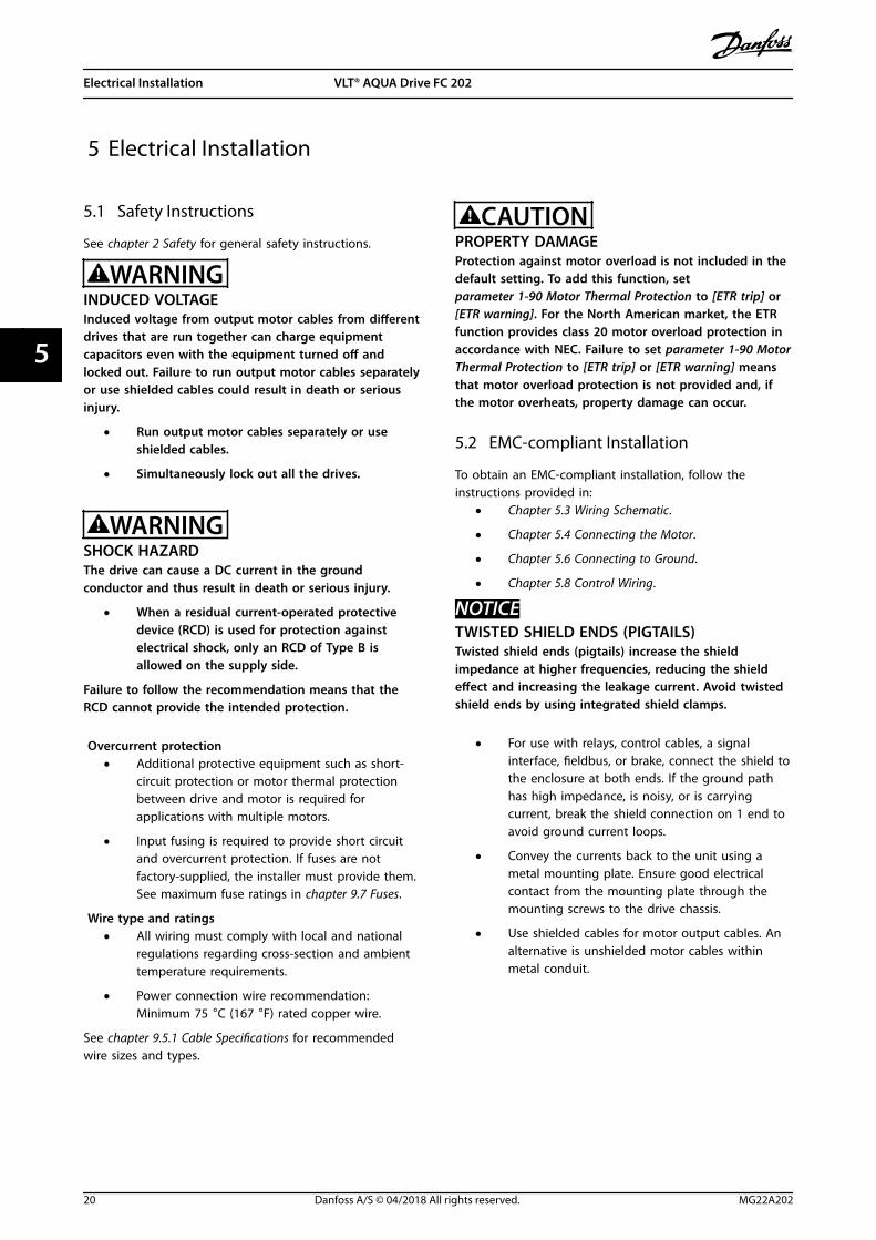
5.1 Safety Instructions
See chapter 2 Safety for general safety instructions.
WARNINGINDUCED VOLTAGEInduced voltage from output motor cables from differentdrives that are run together can charge equipmentcapacitors even with the equipment turned off andlocked out. Failure to run output motor cables separatelyor use shielded cables could result in death or seriousinjury.
• Run output motor cables separately or useshielded cables.
• Simultaneously lock out all the drives.
WARNINGSHOCK HAZARDThe drive can cause a DC current in the groundconductor and thus result in death or serious injury.
• When a residual current-operated protectivedevice (RCD) is used for protection againstelectrical shock, only an RCD of Type B isallowed on the supply side.
Failure to follow the recommendation means that theRCD cannot provide the intended protection.
Overcurrent protection• Additional protective equipment such as short-
circuit protection or motor thermal protectionbetween drive and motor is required forapplications with multiple motors.
• Input fusing is required to provide short circuitand overcurrent protection. If fuses are notfactory-supplied, the installer must provide them.See maximum fuse ratings in chapter 9.7 Fuses.
Wire type and ratings• All wiring must comply with local and national
regulations regarding cross-section and ambienttemperature requirements.
• Power connection wire recommendation:Minimum 75 °C (167 °F) rated copper wire.
See chapter 9.5.1 Cable Specifications for recommendedwire sizes and types.
CAUTIONPROPERTY DAMAGEProtection against motor overload is not included in thedefault setting. To add this function, setparameter 1-90 Motor Thermal Protection to [ETR trip] or[ETR warning]. For the North American market, the ETRfunction provides class 20 motor overload protection inaccordance with NEC. Failure to set parameter 1-90 MotorThermal Protection to [ETR trip] or [ETR warning] meansthat motor overload protection is not provided and, ifthe motor overheats, property damage can occur.
5.2 EMC-compliant Installation
To obtain an EMC-compliant installation, follow theinstructions provided in:
• Chapter 5.3 Wiring Schematic.
• Chapter 5.4 Connecting the Motor.
• Chapter 5.6 Connecting to Ground.
• Chapter 5.8 Control Wiring.
NOTICETWISTED SHIELD ENDS (PIGTAILS)Twisted shield ends (pigtails) increase the shieldimpedance at higher frequencies, reducing the shieldeffect and increasing the leakage current. Avoid twistedshield ends by using integrated shield clamps.
• For use with relays, control cables, a signalinterface, fieldbus, or brake, connect the shield tothe enclosure at both ends. If the ground pathhas high impedance, is noisy, or is carryingcurrent, break the shield connection on 1 end toavoid ground current loops.
• Convey the currents back to the unit using ametal mounting plate. Ensure good electricalcontact from the mounting plate through themounting screws to the drive chassis.
• Use shielded cables for motor output cables. Analternative is unshielded motor cables withinmetal conduit.
Electrical Installation VLT® AQUA Drive FC 202
20 Danfoss A/S © 04/2018 All rights reserved. MG22A202
55

NOTICESHIELDED CABLESIf shielded cables or metal conduits are not used, theunit and the installation do not meet regulatory limitson radio frequency (RF) emission levels.
• Ensure that motor and brake cables are as shortas possible to reduce the interference level fromthe entire system.
• Avoid placing cables with a sensitive signal levelalongside motor and brake cables.
• For communication and command/control lines,follow the particular communication protocolstandards. For example, USB must use shieldedcables, but RS485/ethernet can use shielded UTPor unshielded UTP cables.
• Ensure that all control terminal connections arePELV.
NOTICEEMC INTERFERENCEUse shielded cables for motor and control wiring, andseparate cables for mains input, motor wiring, andcontrol wiring. Failure to isolate power, motor, andcontrol cables can result in unintended behavior orreduced performance. Minimum 200 mm (7.9 in)clearance between mains input, motor, and controlcables are required.
NOTICEINSTALLATION AT HIGH ALTITUDEThere is a risk for overvoltage. Isolation betweencomponents and critical parts could be insufficient, andnot comply with PELV requirements. Reduce the risk forovervoltage by using external protective devices orgalvanic isolation.For installations above 2000 m (6500 ft) altitude, contactDanfoss regarding PELV compliance.
NOTICEPELV COMPLIANCEPrevent electric shock by using protective extra lowvoltage (PELV) electrical supply and complying with localand national PELV regulations.
Electrical Installation Operating Guide
MG22A202 Danfoss A/S © 04/2018 All rights reserved. 21
5 5
130B
F228
.10
L1L2L3PE
PE
u
v
w
2
1
3
5
16
17
18
14
12
8
7
10
9
4
11
13
4
4
6
15
90
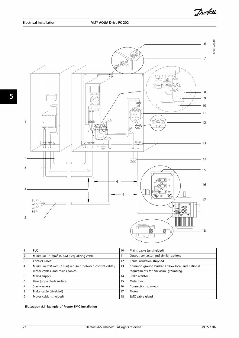
1 PLC 10 Mains cable (unshielded)
2 Minimum 16 mm2 (6 AWG) equalizing cable 11 Output contactor and similar options
3 Control cables 12 Cable insulation stripped
4 Minimum 200 mm (7.9 in) required between control cables,motor cables, and mains cables.
13 Common ground busbar. Follow local and nationalrequirements for enclosure grounding.
5 Mains supply 14 Brake resistor
6 Bare (unpainted) surface 15 Metal box
7 Star washers 16 Connection to motor
8 Brake cable (shielded) 17 Motor
9 Motor cable (shielded) 18 EMC cable gland
Illustration 5.1 Example of Proper EMC Installation
Electrical Installation VLT® AQUA Drive FC 202
22 Danfoss A/S © 04/2018 All rights reserved. MG22A202
55

5.3 Wiring Schematic
e30b
g483
.10
230 V AC50/60 Hz
TB5R1
Regen +
Regen -83
Regen (optional)
1
2
Brake temperature (NC)
Space heater (optional)
91 (L1)92 (L2)93 (L3)
PE
88 (-)89 (+)
50 (+10 V OUT)
53 (A IN)
54 (A IN)
55 (COM A IN)
0/4-20 mA
12 (+24 V OUT)
13 (+24 V OUT)
18 (D IN)
20 (COM D IN)
15 mA 200 mA
(U) 96(V) 97
(W) 98(PE) 99
(COM A OUT) 39
(A OUT) 420/4-20 mA
03
+10 V DC
-10 V DC to +10 V DC
0/4-20 mA
24 V DC
02
01
05
04
06240 V AC, 2A
24 V (NPN) 0 V (PNP)
0 V (PNP)24 V (NPN)
19 (D IN)
24 V (NPN) 0 V (PNP)27
24V
0V
(D IN/OUT)
0 V (PNP)24 V (NPN)
(D IN/OUT)
0V
24V29
24 V (NPN) 0 V (PNP)
0 V (PNP)24 V (NPN)
33 (D IN)
32 (D IN)
12
ON
A53 U-I (S201)
ON2
1A54 U-I (S202)ON=0/4-20 mAOFF=0 to ±10 V
95
400 V AC, 2AP 5-00
(R+) 82
(R-) 81
37 (D IN)1)
+ - + -
(P RS485) 68
(N RS485) 69
(COM RS485) 61
0V
5V
S801
RS485RS485
21 O
N
S801/Bus Term.OFF-ON
3-phasepowerinput
Load share Switch modepower supply
Motor
Analog output
interface
Relay1
Relay2
ON=TerminatedOFF=Open
Brakeresistor
(NPN) = Sink(PNP) = Source
==
=
240 V AC, 2A
400 V AC, 2A-10 V DC to +10 V DC
10 V DC(optional)
(optional)
Illustration 5.2 Basic Wiring Schematic
1) Terminal 37 (optional) is used for Safe Torque Off. Refer to the VLT® FC Series - Safe Torque Off Operating Guide for installationinstructions.
Electrical Installation Operating Guide
MG22A202 Danfoss A/S © 04/2018 All rights reserved. 23
5 5

5.4 Connecting the Motor
WARNINGINDUCED VOLTAGEInduced voltage from output motor cables that run together can charge equipment capacitors, even with theequipment turned off and locked out. Failure to run output motor cables separately or use shielded cables could resultin death or serious injury.
• Comply with local and national electrical codes for cable sizes. For maximum wire sizes, see chapter 9.1 ElectricalData.
• Follow motor manufacturer wiring requirements.
• Motor wiring knockouts or access panels are provided on the pedestal of IP21/IP54 (Type 1/Type 12) units.
• Do not wire a starting or pole-changing device (for example Dahlander motor or slip ring asynchronous motor)between the drive and the motor.
Procedure1. Strip a section of the outer cable insulation.
2. Establish mechanical fixation and electrical contact between the cable shield and ground by positioning thestripped wire under the cable clamp.
3. Connect the ground wire to the nearest grounding terminal in accordance with the grounding instructionsprovided in chapter 5.6 Connecting to Ground.
4. Connect the 3-phase motor wiring to terminals 96 (U), 97 (V), and 98 (W), see Illustration 5.3.
5. Tighten the terminals in accordance with the information provided in chapter 9.10.1 Fastener Torque Ratings.
Electrical Installation VLT® AQUA Drive FC 202
24 Danfoss A/S © 04/2018 All rights reserved. MG22A202
55

130B
F150
.10
U/T1 96 V/T2 97 W/T3 98
FASTENER TORQUE M10 19Nm (14FT-LB), M12 35Nm (26FT-LB)
U/T1 96 V/T2 97 W/T3 98
FASTENER TORQUE M10 19Nm (14FT-LB), M12 35Nm (14FT-LB)
+ REGEN 82FASTENER TORQUE:M10 19Nm (14FT-LB)M12 35Nm (26FT-LB)
- REGEN 83FASTENER TORQUE:M10 19Nm (14FT-LB)M12 35Nm (26FT-LB)
Illustration 5.3 AC motor terminals (E1h shown). For a detailed view of terminals, refer to chapter 5.7 Terminal Dimensions.
Electrical Installation Operating Guide
MG22A202 Danfoss A/S © 04/2018 All rights reserved. 25
5 5

5.5 Connecting the AC Mains
• Size the wiring according to the input current of the drive. For maximum wire sizes, see chapter 9.1 Electrical Data.
• Comply with local and national electrical codes for cable sizes.
Procedure1. Strip a section of the outer cable insulation.
2. Establish mechanical fixation and electrical contact between the cable shield and ground by positioning thestripped wire under the cable clamp.
3. Connect the ground wire to the nearest grounding terminal in accordance with the grounding instructionsprovided in chapter 5.6 Connecting to Ground.
4. Connect the 3-phase AC input power wiring to terminals R, S, and T (see Illustration 5.4).
5. Tighten the terminals in accordance with the information provided in chapter 9.10.1 Fastener Torque Ratings.
6. When supplied from an isolated mains source (IT mains or floating delta) or TT/TN-S mains with a grounded leg(grounded delta), ensure that parameter 14-50 RFI Filter is set to [0] Off to avoid damage to the DC link and toreduce ground capacity currents.
NOTICEOUTPUT CONTACTORDanfoss does not recommend using an output contactor on 525–590 V drives that are connected to an IT mainsnetwork.
Electrical Installation VLT® AQUA Drive FC 202
26 Danfoss A/S © 04/2018 All rights reserved. MG22A202
55

130B
F151
.10
T/L3 93S/L2 92R/L1 91FASTENER TORQUE M10 19Nm (14FT-LB), M12 35Nm (26FT-LB)
T/L3 93S/L2 92R/L1 91FASTENER TORQUE M10 19Nm (14FT-LB), M12 35Nm (26FT-LB)
Illustration 5.4 AC mains terminals (E1h shown). For a detailed view of terminals, refer to chapter 5.7 Terminal Dimensions.
Electrical Installation Operating Guide
MG22A202 Danfoss A/S © 04/2018 All rights reserved. 27
5 5

5.6 Connecting to Ground
WARNINGLEAKAGE CURRENT HAZARDLeakage currents exceed 3.5 mA. Failure to ground the drive properly can result in death or serious injury.
• Ensure the correct grounding of the equipment by a certified electrical installer.
For electrical safety• Ground the drive in accordance with applicable standards and directives.
• Use a dedicated ground wire for input power, motor power, and control wiring.
• Do not ground 1 drive to another in a daisy chain fashion.
• Keep the ground wire connections as short as possible.
• Follow motor manufacturer wiring requirements.
• Minimum cable cross-section: 10 mm2 (6 AWG) (or 2 rated ground wires terminated separately).
• Tighten the terminals in accordance with the information provided in chapter 9.10.1 Fastener Torque Ratings.
For EMC-compliant installation• Establish electrical contact between the cable shield and the drive enclosure by using metal cable glands or by
using the clamps provided on the equipment.
• Reduce burst transient by using high-strand wire.
• Do not use pigtails.
NOTICEPOTENTIAL EQUALIZATIONThere is a risk of burst transient when the ground potential between the drive and the control system is different.Install equalizing cables between the system components. Recommended cable cross-section: 16 mm2 (5 AWG).
Electrical Installation VLT® AQUA Drive FC 202
28 Danfoss A/S © 04/2018 All rights reserved. MG22A202
55

130B
F152
.10
U/T1 96 V/T2 97 W/T3 98T/L3 93S/L2 92R/L1 91
FASTENER TORQUE M10 19Nm (14FT-LB), M12 35Nm (26FT-LB) FASTENER TORQUE M10 19Nm (14FT-LB), M12 35Nm (26FT-LB)
U/T1 96 V/T2 97 W/T3 98T/L3 93S/L2 92R/L1 91
FASTENER TORQUE M10 19Nm (14FT-LB), M12 35Nm (26FT-LB) FASTENER TORQUE M10 19Nm (14FT-LB), M12 35Nm (26FT-LB)
Illustration 5.5 Ground terminals (E1h shown). For a detailed view of terminals, refer to chapter 5.7 Terminal Dimensions.
Electrical Installation Operating Guide
MG22A202 Danfoss A/S © 04/2018 All rights reserved. 29
5 5

5.7 Terminal Dimensions
5.7.1 E1h Terminal Dimensions
130B
F683
.10
6X 613 (24.1)
383
(15.
1)
472
(18.
6)
423
(16.
7)
165
(6.5
)
0 (0
.0)
101
(4.0
)
82 (3
.2)
721 (28.4)
0 (0.0)
1
2
3
200 (7.9)
515 (20.3)
485 (19.1)
248
(9.8
)
241
(9.5
)
171
(6.7
)
414
(16.
3)
361
(14.
2)
331
(13.
0)
501
(19.
7)
497
(19.
6)
431
(17.
0)
512
(20.
2)
4
1 Mains terminals 3 Motor terminals
2 Brake or regeneration terminals 4 Ground terminals, M10 nut
Illustration 5.6 E1h Terminal Dimensions (Front View)
Electrical Installation VLT® AQUA Drive FC 202
30 Danfoss A/S © 04/2018 All rights reserved. MG22A202
55

130B
F650
.10A
A
649 (25.5)649 (25.5)
0 (0.0)0 (0.0)
0 (0
.0)
164
(6.4
)
290
(11.
4)
377
(14.
8)
0 (0
.0)
164
(6.4
)
290
(11.
4)
18 (0
.7)
0 (0
.0)
84 (3
.3)
42 (1
.7)
5X
0 (0.0)
36 (1.4)
44 (1.8)
14 (0.5)
Illustration 5.7 E1h Terminal Dimensions (Side Views)
Electrical Installation Operating Guide
MG22A202 Danfoss A/S © 04/2018 All rights reserved. 31
5 5

5.7.2 E2h Terminal Dimensions
130B
F689
.10
721 (28.4)
6X 613 (24.1)
1
515 (20.3)
485 (19.1)
0 (0.0)
200 (7.9)
185
(7.3
)
0 (0
.0)
101
(4.0
)
89 (3
.5)
289
(11.
4)
281
(11.
1)
195
(7.7
)
483
(19.
0)
409
(16.
1)
387
(15.
2)
597
(23.
5)
579
(22.
8)
503
(19.
8)
479
(18.
9)
568
(22.
4)
519
(20.
4)
608
(23.
9)
2
3
4
1 Mains terminals 3 Motor terminals
2 Brake or regeneration terminals 4 Ground terminals, M10 nut
Illustration 5.8 E2h Terminal Dimensions (Front View)
Electrical Installation VLT® AQUA Drive FC 202
32 Danfoss A/S © 04/2018 All rights reserved. MG22A202
55

649 (25.5)649 (25.5)
0 (0.0)0 (0.0)
0 (0
.0)
164
(6.4
)
290
(11.
4)
377
(14.
8)
0 (0
.0)
164
(6.4
)
290
(11.
4)
130B
F690
.10
A
18 (0
.7)
0 (0
.0)
84 (3
.3)
42 (1
.7)
5X
0 (0.0)
36 (1.4)
44 (1.8)
14 (0.5)
A
Illustration 5.9 E2h Terminal Dimensions (Side Views)
Electrical Installation Operating Guide
MG22A202 Danfoss A/S © 04/2018 All rights reserved. 33
5 5

5.7.3 E3h Terminal Dimensions
130B
F660
.10
336
(13.
2)
425
(16.
7)
376
(14.
8)
465
(18.
3)
256 (10.1)
33 (1.3)
6X 148 (5.8)
90 (3.5)
50 (2.0)
0 (0.0)
0 (0
.0)
64 (2
.5)
35 (1
.4)
91 (3
.6)
118
(4.6
)
194
(7.6
)
174
(6.9
)
201
(7.9
)
284
(11.
2)
340
(13.
4)
314
(12.
3)
367
(14.
4)
444
(17.
5)
423
(16.
7)
450
(17.
7)
2
3
4
1
1 Mains terminals 3 Motor terminals
2 Brake or regeneration terminals 4 Ground terminals, M8 and M10 nuts
Illustration 5.10 E3h Terminal Dimensions (Front View)
Electrical Installation VLT® AQUA Drive FC 202
34 Danfoss A/S © 04/2018 All rights reserved. MG22A202
55

130B
F661
.10
0 (0.0) 0 (0.0)
160
(6.3
)
0 (0
.0)
373
(14.
7)
287
(11.
3)
287
(11.
3)
160
(6.3
)
0 (0
.0)
184(7.2)
184(7.2)
A5X 14 (0.5)
44 (1.8)
0 (0.0)
36 (1.4)
18 (0
.7)
0 (0
.0)
84 (3
.3)
42 (1
.7)
A
Illustration 5.11 E3h Mains, Motor, and Ground Terminal Dimensions (Side Views)
Electrical Installation Operating Guide
MG22A202 Danfoss A/S © 04/2018 All rights reserved. 35
5 5

130B
F663
.10
0 (0
.0)
234
(9.2
)
314
(12.
4)
0 (0
.0)
176
(6.9
)
A
A
8X 14 (0.5)
20 (0.8)
0 (0.0)
35(1.4)
0 (0
.0)
15 (0
.6)
35 (1
.4)
50 (2
.0)
75 (3
.0)
90 (3
.5)
125
(4.9
)
140
(5.5
)
2X 125 (4.9)
0 (0.0)
Illustration 5.12 E3h Load Share/Regeneration Terminal Dimensions
Electrical Installation VLT® AQUA Drive FC 202
36 Danfoss A/S © 04/2018 All rights reserved. MG22A202
55

5.7.4 E4h Terminal Dimensions
130B
F668
.10
6X 148 (5.8)
90 (3.5)
50 (2.0)
0 (0.0)
1
0 (0
.0)
64 (2
.5)
41 (1
.6)
105
(4.1
)
137
(5.4
)
194
(7.6
)
200
(7.9
)
233
(9.2
)
402
(15.
8)
339
(13.
4)
410
(16.
1)
499
(19.
6)
435
(17.
1)
531
(20.
9)
256 (10.1)
33 (1.3)
2
3
4
540
(21.
2)
432
(17.
0)
521
(20.
5)
472
(18.
6)
561
(22.
1)
1 Mains terminals 3 Motor terminals
2 Brake or regeneration terminals 4 Ground terminals, M8 and M10 nuts
Illustration 5.13 E4h Terminal Dimensions (Front View)
Electrical Installation Operating Guide
MG22A202 Danfoss A/S © 04/2018 All rights reserved. 37
5 5

130B
F681
.10
5X 14 (0.5)
44 (1.8)
0 (0.0)
36 (1.4)
0 (0.0)
373
(14.
7)
287
(11.
3)
160
(6.3
)
0 (0
.0)
0 (0.0)
160
(6.3
)
0 (0
.0)
287
(11.
3)
184(7.2)
184(7.2)
A
18 (0
.7)
0 (0
.0)
84 (3
.3)
42 (1
.7)
Illustration 5.14 E4h Mains, Motor, and Ground Terminal Dimensions (Side Views)
Electrical Installation VLT® AQUA Drive FC 202
38 Danfoss A/S © 04/2018 All rights reserved. MG22A202
55

130B
F682
.10
A
20 (0.8)
0 (0.0)
35(1.4)
0 (0
.0)
15 (0
.6)
35 (1
.4)
50 (2
.0)
75 (3
.0)
90 (3
.5)
125
(4.9
)
140
(5.5
)
8X 14 (0.5)
2X 125 (4.9)
0 (0.0)
0 (0
.0)
234
(9.2
)
314
(12.
4)
0 (0
.0)
219
(8.6
)
A
Illustration 5.15 E4h Load Share/Regeneration Terminal Dimensions
Electrical Installation Operating Guide
MG22A202 Danfoss A/S © 04/2018 All rights reserved. 39
5 5

5.8 Control Wiring
All terminals to the control cables are inside the drivebelow the LCP. To access, either open the door (E1h andE2h) or remove the front panel (E3h and E4h).
5.8.1 Control Cable Routing
Tie down and route all control wires as shown inIllustration 5.16. Remember to connect the shields in aproper way to ensure optimum electrical immunity.
• Isolate control wiring from high-power cables inthe drive.
• When the drive is connected to a thermistor,ensure that the thermistor control wiring isshielded and reinforced/double insulated. A 24 VDC supply voltage is recommended.
Fieldbus connectionConnections are made to the relevant options on thecontrol card. For more detail, see the relevant fieldbusinstruction. The cable must be tied down and routed alongwith other control wires inside the unit. SeeIllustration 5.16.
130B
F715
.10
Illustration 5.16 Control Card Wiring Path
5.8.2 Control Terminal Types
Illustration 5.17 shows the removable drive connectors.Terminal functions and default settings are summarized inTable 5.1 – Table 5.3.
130B
F144
.10
Illustration 5.17 Control Terminal Locations
12 13 18 19 27 29 32 33 20 37
39696861 42 50 53 54 55
130B
F145
.10
1
2
3
1 Serial communication terminals
2 Digital input/output terminals
3 Analog input/output terminals
Illustration 5.18 Terminal Numbers Located on the Connectors
Terminal Parameter Defaultsetting
Description
61 – – Integrated RC-filter forcable shield. ONLY forconnecting the shieldin the event of EMCproblems.
Electrical Installation VLT® AQUA Drive FC 202
40 Danfoss A/S © 04/2018 All rights reserved. MG22A202
55

Terminal Parameter Defaultsetting
Description
68 (+) Parametergroup 8-3* FCPort Settings
– RS485 interface. Aswitch (BUS TER.) isprovided on thecontrol card for busterminationresistance. SeeIllustration 5.23.
69 (-) Parametergroup 8-3* FCPort Settings
–
Table 5.1 Serial Communication Terminal Descriptions
Digital input/output terminals
Terminal Parameter Defaultsetting
Description
12, 13 – +24 V DC 24 V DC supplyvoltage for digitalinputs and externaltransducers.Maximum outputcurrent 200 mA for all24 V loads.
18 Parameter 5-10 Terminal 18Digital Input
[8] Start Digital inputs.
19 Parameter 5-11 Terminal 19Digital Input
[10]Reversing
32 Parameter 5-14 Terminal 32Digital Input
[0] Nooperation
33 Parameter 5-15 Terminal 33Digital Input
[0] Nooperation
27 Parameter 5-12 Terminal 27Digital Input
[2] Coastinverse
For digital input oroutput. Defaultsetting is input.
29 Parameter 5-13 Terminal 29Digital Input
[14] JOG
20 – – Common for digitalinputs and 0 Vpotential for 24 Vsupply.
37 – STO When not using theoptional STO feature,a jumper wire isrequired betweenterminal 12 (or 13)and terminal 37. Thisset-up allows thedrive to operate withfactory defaultprogramming values.
Table 5.2 Digital Input/Output Terminal Descriptions
Analog input/output terminals
Terminal Parameter Defaultsetting
Description
39 – – Common for analogoutput.
42 Parameter 6-50 Terminal 42
Output
[0] Nooperation
Programmable analogoutput. 0–20 mA or4–20 mA at a
maximum of 500 Ω.
50 – +10 V DC 10 V DC analogsupply voltage forpotentiometer orthermistor. 15 mAmaximum.
53 Parametergroup 6-1*
Analog Input 1
Reference Analog input. Forvoltage or current.Switches A53 andA54 select mA or V.54 Parameter
group 6-2*Analog Input 2
Feedback
55 – – Common for analoginput.
Table 5.3 Analog Input/Output Terminal Descriptions
5.8.3 Relay Terminals
RELAY 1 RELAY 2
01 02 03 04 05 06
130B
F156
.10
Illustration 5.19 Relay 1 and Relay 2 Terminals
• Relay 1 and relay 2. The location of the outputsdepends on the drive configuration. See chapter 3.5 Control Shelf.
• Terminals on built-in optional equipment. See themanual provided with the equipment option.
Terminal Parameter Defaultsetting
Description
01, 02, 03 Parameter 5-40 Function Relay
[0]
[0] Nooperation
Form C relay output.For AC or DC voltageand resistive orinductive loads.04, 05, 06 Parameter 5-40
Function Relay[1]
[0] Nooperation
Table 5.4 Relay Terminal Descriptions
Electrical Installation Operating Guide
MG22A202 Danfoss A/S © 04/2018 All rights reserved. 41
5 5

5.8.4 Wiring to Control Terminals
The control terminals are located near the LCP. The controlterminal connectors can be unplugged from the drive forconvenience when wiring, as shown in Illustration 5.17.Either solid or flexible wire can be connected to thecontrol terminals. Use the following procedures to connector disconnect the control wires.
NOTICEMinimize interference by keeping control wires as shortas possible and separate from high-power cables.
Connecting wire to control terminals
1. Strip 10 mm (0.4 in) of the outer plastic layerfrom the end of the wire.
2. Insert the control wire into the terminal.
• For a solid wire, push the bare wire intothe contact. See Illustration 5.20.
• For a flexible wire, open the contact byinserting a small screwdriver into theslot between the terminal holes andpush the screwdriver inward. SeeIllustration 5.21 Then, insert the strippedwire into the contact and remove thescrewdriver.
3. Pull gently on the wire to ensure that the contactis firmly established and not loose. Loose controlwiring can be the source of equipment faults orreduced performance.
e30b
g283
.10
10 m
m (0
.4)
12 13 18 19 27 29 32 33
Illustration 5.20 Connecting Solid Control Wires
130B
D54
6.11
21
12 13 18 19 27 29 32 33
10 m
m (0
.4)
Illustration 5.21 Connecting Flexible Control Wires
Disconnecting wires from the control terminals
1. To open the contact, insert a small screwdriverinto the slot between the terminal holes andpush the screwdriver inward.
2. Pull gently on the wire to free it from the controlterminal contact.
See chapter 9.1 Electrical Data for control terminal wiringsizes and chapter 7 Wiring Configuration Examples fortypical control wiring connections.
5.8.5 Enabling Motor Operation(Terminal 27)
A jumper wire is required between terminal 12 (or 13) andterminal 27 for the drive to operate when using factorydefault programming values.
• Digital input terminal 27 is designed to receive24 V DC external interlock command.
• When no interlock device is used, wire a jumperbetween control terminal 12 (recommended) or13 to terminal 27. This wire provides an internal24 V signal on terminal 27.
• When the status line at the bottom of the LCPreads AUTO REMOTE COAST, the unit is ready tooperate, but is missing an input signal onterminal 27.
• When factory-installed optional equipment iswired to terminal 27, do not remove that wiring.
NOTICEThe drive cannot operate without a signal on terminal27, unless terminal 27 is reprogrammed usingparameter 5-12 Terminal 27 Digital Input.
Electrical Installation VLT® AQUA Drive FC 202
42 Danfoss A/S © 04/2018 All rights reserved. MG22A202
55

5.8.6 Configuring RS485 SerialCommunication
RS485 is a 2-wire bus interface compatible with multi-dropnetwork topology, and it contains the following features:
• Either Danfoss FC or Modbus RTU communicationprotocol, which are internal to the drive, can beused.
• Functions can be programmed remotely usingthe protocol software and RS485 connection or inparameter group 8-** Communications andOptions.
• Selecting a specific communication protocolchanges various default parameter settings tomatch the specifications of the protocol, makingmore protocol-specific parameters available.
• Option cards for the drive are available to providemore communication protocols. See the optioncard documentation for installation and operationinstructions.
• A switch (BUS TER) is provided on the controlcard for bus termination resistance. SeeIllustration 5.23.
For basic serial communication set-up, perform thefollowing steps:
1. Connect RS485 serial communication wiring toterminals (+)68 and (-)69.
1a Use shielded serial communication cable(recommended).
1b See chapter 5.6 Connecting to Ground forproper grounding.
2. Select the following parameter settings:
2a Protocol type in parameter 8-30 Protocol.
2b Drive address in parameter 8-31 Address.
2c Baud rate in parameter 8-32 Baud Rate.
61
68
69
+
130B
B489
.10
RS485
Illustration 5.22 Serial Communication Wiring Diagram
5.8.7 Wiring Safe Torque Off (STO)
The Safe Torque Off (STO) function is a component in asafety control system. STO prevents the unit fromgenerating the voltage required to rotate the motor.
To run STO, more wiring for the drive is required. Refer toSafe Torque Off Operating Guide for further information.
5.8.8 Wiring the Space Heater
The space heater is an option used to prevent conden-sation from forming inside the enclosure when the unit isturned off. It is designed to be field wired and controlledby an HVAC management system.
Specifications• Nominal voltage: 100–240
• Wire size: 12–24 AWG
5.8.9 Wiring the Auxiliary Contacts to theDisconnect
The disconnect is an option that is installed at the factory.The auxiliary contacts, which are signal accessories usedwith the disconnect, are not installed at the factory toallow more flexibility during installation. The contacts snapinto place without the need for tools.
Contacts must be installed in specific locations on thedisconnect depending upon their functions. Refer to thedatasheet included in the accessory bag that comes withthe drive.
Specifications• Ui/[V]: 690
• Uimp/[kV]: 4
• Pollution degree: 3
• Ith/[A]: 16
• Cable size: 1...2x0.75...2.5 mm2
• Maximum fuse: 16 A/gG
• NEMA: A600, R300, wire size: 18–14 AWG, 1(2)
Electrical Installation Operating Guide
MG22A202 Danfoss A/S © 04/2018 All rights reserved. 43
5 5

5.8.10 Wiring the Brake ResistorTemperature Switch
The brake resistor terminal block is located on the powercard and allows for the connection of an external brakeresistor temperature switch. The switch can be configuredas normally closed or normally open. If the input changes,a signal trips the drive and shows alarm 27, Brake chopperfault on the LCP display. At the same time, the drive stopsbraking and the motor coasts.
1. Locate the brake resistor terminal block (terminals104–106) on the power card. See Illustration 3.3.
2. Remove the M3 screws that hold the jumper tothe power card.
3. Remove the jumper and wire the brake resistortemperature switch in 1 of the following configu-rations:
3a Normally closed. Connect to terminals104 and 106.
3b Normally open. Connect to terminals104 and 105.
4. Secure the switch wires with the M3 screws.Torque to 0.5-0.6 Nm (5 in-lb).
5.8.11 Selecting Voltage/Current InputSignal
The analog input terminals 53 and 54 allow setting ofinput signal to voltage (0–10 V) or current (0/4–20 mA).
Default parameter setting:• Terminal 53: Speed reference signal in open loop
(see parameter 16-61 Terminal 53 Switch Setting).
• Terminal 54: Feedback signal in closed loop (seeparameter 16-63 Terminal 54 Switch Setting).
NOTICEDisconnect power to the drive before changing switchpositions.
1. Remove the LCP (local control panel).See chapter 6.3 LCP Menu.
2. Remove any optional equipment covering theswitches.
3. Set switches A53 and A54 to select the signaltype (U = voltage, I = current).
130B
F146
.10
BUS TER.OFF-ONA53 A54U- I U- I
12
N
O
12
N
O
12
N
O
12
N
O
Illustration 5.23 Location of Terminal 53 and 54 Switches
Electrical Installation VLT® AQUA Drive FC 202
44 Danfoss A/S © 04/2018 All rights reserved. MG22A202
55

5.9 Pre-start Check List
Before completing installation of the unit, inspect the entire installation as detailed in Table 5.5. Check and mark the itemswhen completed.
Inspect for Description Motor • Confirm continuity of the motor by measuring ohm values on U–V (96–97), V–W (97–98), and W–U (98–96).
• Confirm that the supply voltage matches the voltage of the drive and the motor.
Switches • Ensure that all switch and disconnect settings are in the proper positions.
Auxiliary equipment • Look for auxiliary equipment, switches, disconnects, or input fuses/circuit breakers that reside on the inputpower side of the drive or output side to the motor. Ensure that they are ready for full-speed operation.
• Check function and installation of any sensors used for feedback to the drive.
• Remove any power factor correction caps on motor.
• Adjust any power factor correction caps on the mains side and ensure that they are dampened.
Cable routing • Ensure that motor wiring, brake wiring (if equipped), and control wiring are separated or shielded, or in 3separate metallic conduits for high-frequency interference isolation.
Control wiring • Check for broken or damaged wires and loose connections.
• Check that control wiring is isolated from high-power wiring for noise immunity.
• Check the voltage source of the signals, if necessary.
• Use shielded cable or twisted pair and ensure that the shield is terminated correctly.
Input and outputpower wiring
• Check for loose connections.
• Check that motor and mains are in separate conduit or separated shielded cables.
Grounding • Check for good ground connections that are tight and free of oxidation.
• Grounding to conduit, or mounting the back panel to a metal surface, is not a suitable grounding.
Fuses and circuitbreakers
• Check for proper fusing or circuit breakers.
• Check that all fuses are inserted firmly and are in operational condition and that all circuit breakers (ifused) are in the open position.
Cooling clearance • Look for any obstructions in the airflow path.
• Measure top and bottom clearance of the drive to verify adequate airflow for cooling, see chapter 4.5.1 Installation and Cooling Requirements.
Ambient conditions • Check that requirements for ambient conditions are met. See chapter 9.4 Ambient Conditions.
Interior of the drive • Inspect that the unit interior is free of dirt, metal chips, moisture, and corrosion.
• Verify that all installation tools have been removed from unit interior.
• For E3h and E4h enclosures, ensure that the unit is mounted on an unpainted, metal surface.
Vibration • Check that the unit is mounted solidly, or that shock mounts are used, if necessary.
• Check for an unusual amount of vibration.
Table 5.5 Pre-start Check List
CAUTIONPOTENTIAL HAZARD IN THE EVENT OF INTERNAL FAILUREIf the drive is not properly secured with covers, personal injury can occur.
• Before applying power, ensure all safety covers (door and panels) are in place and securely fastened. Refer tochapter 9.10.1 Fastener Torque Ratings.
Electrical Installation Operating Guide
MG22A202 Danfoss A/S © 04/2018 All rights reserved. 45
5 5

6 Commissioning
6.1 Safety Instructions
See chapter 2 Safety for general safety instructions.
WARNINGHIGH VOLTAGEDrives contain high voltage when connected to AC mainsinput power. Failure to use qualified personnel to install,start up, and maintain the drive can result in death orserious injury.
• Only qualified personnel must install, start up,and maintain the drive.
Before applying power:1. Ensure that input power to the unit is OFF and
locked out. Do not rely on the drive disconnectswitches for input power isolation.
2. Verify that there is no voltage on input terminalsL1 (91), L2 (92), and L3 (93), phase-to-phase, andphase-to-ground.
3. Verify that there is no voltage on outputterminals 96 (U), 97 (V), and 98 (W), phase-to-phase, and phase-to-ground.
4. Confirm continuity of the motor by measuringohm values on U–V (96–97), V–W (97–98), and W–U (98–96).
5. Check for proper grounding of the drive and themotor.
6. Inspect the drive for loose connections on theterminals.
7. Check that all cable glands are firmly tightened.
8. Confirm that the supply voltage matches thevoltage of the drive and the motor.
9. Close and securely fasten the front cover.
6.2 Applying Power
WARNINGUNINTENDED STARTWhen the drive is connected to AC mains, DC supply, orload sharing, the motor may start at any time, causingrisk of death, serious injury, and equipment, or propertydamage. The motor may start by activation of anexternal switch, a fieldbus command, an input referencesignal from the LCP or LOP, via remote operation usingMCT 10 Set-up software, or after a cleared faultcondition.
To prevent unintended motor start:• Press [Off] on the LCP before programming
parameters.
• Disconnect the drive from mains wheneverpersonal safety considerations make itnecessary to avoid unintended motor start.
• Check that the drive, motor, and any drivenequipment is in operational readiness.
1. Confirm that the input voltage between phases isbalanced within 3%. If not, correct input voltageimbalance before proceeding. Repeat thisprocedure after the voltage correction.
2. Ensure that optional equipment wiring, if present,matches the installation application.
3. Ensure that all operator devices are in the OFFposition.
4. Close all panel doors and securely fasten allcovers.
5. Apply power to the unit. DO NOT start the drivenow. For units with a disconnect switch, turn tothe ON position to apply power to the drive.
NOTICEIf the status line at the bottom of the LCP reads AUTOREMOTE COASTING or alarm 60, External Interlock isshown, this status indicates that the unit is ready tooperate but is missing an input signal on terminal 27.See chapter 5.8.5 Enabling Motor Operation (Terminal 27)for details.
Commissioning VLT® AQUA Drive FC 202
46 Danfoss A/S © 04/2018 All rights reserved. MG22A202
66
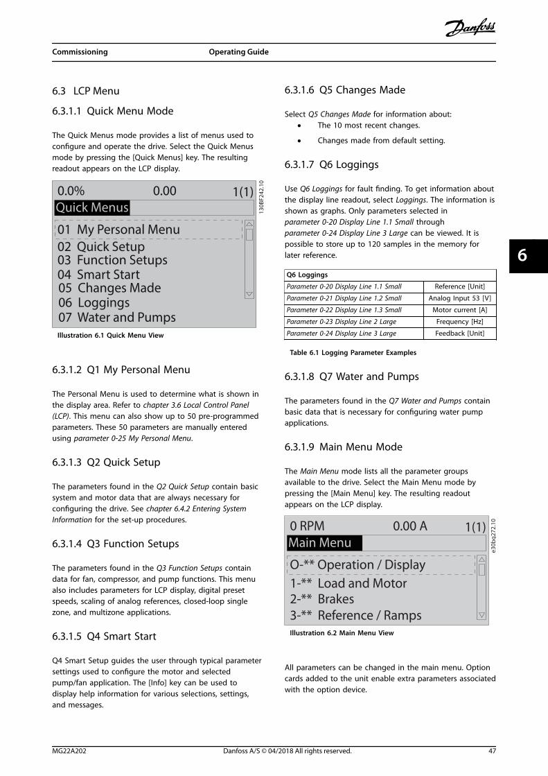
6.3 LCP Menu
6.3.1.1 Quick Menu Mode
The Quick Menus mode provides a list of menus used toconfigure and operate the drive. Select the Quick Menusmode by pressing the [Quick Menus] key. The resultingreadout appears on the LCP display.
130B
F242
.10
01 My Personal Menu02 Quick Setup
05 Changes Made06 Loggings
0.0% 0.00Quick Menus
1(1)
07 Water and Pumps
03 Function Setups04 Smart Start
Illustration 6.1 Quick Menu View
6.3.1.2 Q1 My Personal Menu
The Personal Menu is used to determine what is shown inthe display area. Refer to chapter 3.6 Local Control Panel(LCP). This menu can also show up to 50 pre-programmedparameters. These 50 parameters are manually enteredusing parameter 0-25 My Personal Menu.
6.3.1.3 Q2 Quick Setup
The parameters found in the Q2 Quick Setup contain basicsystem and motor data that are always necessary forconfiguring the drive. See chapter 6.4.2 Entering SystemInformation for the set-up procedures.
6.3.1.4 Q3 Function Setups
The parameters found in the Q3 Function Setups containdata for fan, compressor, and pump functions. This menualso includes parameters for LCP display, digital presetspeeds, scaling of analog references, closed-loop singlezone, and multizone applications.
6.3.1.5 Q4 Smart Start
Q4 Smart Setup guides the user through typical parametersettings used to configure the motor and selectedpump/fan application. The [Info] key can be used todisplay help information for various selections, settings,and messages.
6.3.1.6 Q5 Changes Made
Select Q5 Changes Made for information about:• The 10 most recent changes.
• Changes made from default setting.
6.3.1.7 Q6 Loggings
Use Q6 Loggings for fault finding. To get information aboutthe display line readout, select Loggings. The information isshown as graphs. Only parameters selected inparameter 0-20 Display Line 1.1 Small throughparameter 0-24 Display Line 3 Large can be viewed. It ispossible to store up to 120 samples in the memory forlater reference.
Q6 Loggings
Parameter 0-20 Display Line 1.1 Small Reference [Unit]
Parameter 0-21 Display Line 1.2 Small Analog Input 53 [V]
Parameter 0-22 Display Line 1.3 Small Motor current [A]
Parameter 0-23 Display Line 2 Large Frequency [Hz]
Parameter 0-24 Display Line 3 Large Feedback [Unit]
Table 6.1 Logging Parameter Examples
6.3.1.8 Q7 Water and Pumps
The parameters found in the Q7 Water and Pumps containbasic data that is necessary for configuring water pumpapplications.
6.3.1.9 Main Menu Mode
The Main Menu mode lists all the parameter groupsavailable to the drive. Select the Main Menu mode bypressing the [Main Menu] key. The resulting readoutappears on the LCP display.
e30b
g272
.10
O-** Operation / Display1-** Load and Motor2-** Brakes3-** Reference / Ramps
0 RPM 0.00 AMain Menu
1(1)
Illustration 6.2 Main Menu View
All parameters can be changed in the main menu. Optioncards added to the unit enable extra parameters associatedwith the option device.
Commissioning Operating Guide
MG22A202 Danfoss A/S © 04/2018 All rights reserved. 47
6 6

6.4 Programming the Drive
For detailed information on the key functions on the localcontrol panel (LCP), see chapter 3.6 Local Control Panel(LCP). For information on parameter settings, see theprogramming guide.
Parameter overviewParameter settings control the operation of the drive, andare accessed via the LCP. These settings are assigned adefault value at the factory, but can be configured for theirunique application. Each parameter has a name andnumber that remain the same regardless of theprogramming mode.
In the Main Menu mode, the parameters are divided intogroups. The first digit of the parameter number (from theleft) indicates the parameter group number. The parametergroup is then broken down into subgroups, if necessary.For example:
0-** Operation/Display Parameter group
0-0* Basic Settings Parameter subgroup
Parameter 0-01 Language Parameter
Parameter 0-02 Motor Speed Unit Parameter
Parameter 0-03 Regional Settings Parameter
Table 6.2 Example of Parameter Group Hierarchy
Moving around parametersNavigate through the parameters using the following LCPkeys:
• Press [] [] to scroll up or down.
• Press [] [] to shift a space to the left or right ofa decimal point while editing a decimalparameter value.
• Press [OK] to accept the change.
• Press [Cancel] to disregard the change and exitedit mode.
• Press [Back] twice to show the status view.
• Press [Main Menu] once to go back to the mainmenu.
6.4.1 Programming Example for an Open-loop Application
This procedure, which is used to configure a typical open-loop application, programs the drive to receive a 0–10 VDC analog control signal on input terminal 53. The driveresponds by providing 20–50 Hz output to the motorproportional to the input signal (0–10 V DC=20–50 Hz).
Press [Quick Menu] and complete the following steps:1. Select Q3 Function Setups and press [OK].
2. Select Parameter Data Set and press [OK].
130B
T112
.12
Q1 My Personal Menu
Q2 Quick Setup
Q3 Function Setups
Q5 Changes Made
69.3% 5.20A 1(1)
Quick Menus
Illustration 6.3 Q3 Function Setups
3. Select Q3-2 Open Loop Settings and press [OK].
130B
F725
.10
Q3
Q3-1 General Settings
Q3-2 Open Loop Settings
Q3-3 Closed Loop Settings
Q3-4 Application Settings
28.4% 2.05A 1(1)
Function Setups
Illustration 6.4 Q3-2 Open Loop Settings
4. Select Q3-21 Analog Reference and press [OK].
130B
F726
.10
Q3-2
Q3-20 Digital Reference
Q3-21 Analog Reference
14.7% 0.00A 1(1)
Open Loop Settings
Illustration 6.5 Q3-21 Analog Reference
Commissioning VLT® AQUA Drive FC 202
48 Danfoss A/S © 04/2018 All rights reserved. MG22A202
66
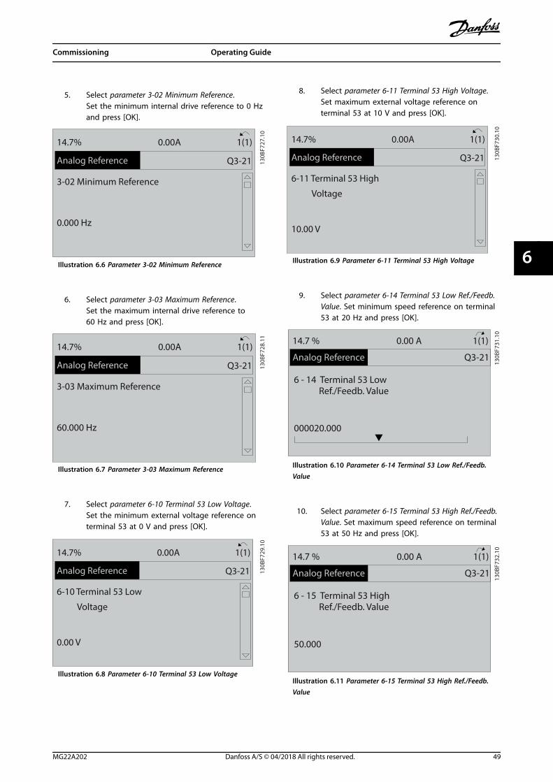
5. Select parameter 3-02 Minimum Reference.Set the minimum internal drive reference to 0 Hzand press [OK].
130B
F727
.10
Q3-21
3-02 Minimum Reference
0.000 Hz
14.7% 0.00A 1(1)
Analog Reference
Illustration 6.6 Parameter 3-02 Minimum Reference
6. Select parameter 3-03 Maximum Reference.Set the maximum internal drive reference to60 Hz and press [OK].
130B
F728
.11
Q3-21
3-03 Maximum Reference
60.000 Hz
14.7% 0.00A 1(1)
Analog Reference
Illustration 6.7 Parameter 3-03 Maximum Reference
7. Select parameter 6-10 Terminal 53 Low Voltage.Set the minimum external voltage reference onterminal 53 at 0 V and press [OK].
130B
F729
.10
Q3-21
6-10 Terminal 53 Low
Voltage
0.00 V
14.7% 0.00A 1(1)
Analog Reference
Illustration 6.8 Parameter 6-10 Terminal 53 Low Voltage
8. Select parameter 6-11 Terminal 53 High Voltage.Set maximum external voltage reference onterminal 53 at 10 V and press [OK].
130B
F730
.10
Q3-21
6-11 Terminal 53 High
Voltage
10.00 V
14.7% 0.00A 1(1)
Analog Reference
Illustration 6.9 Parameter 6-11 Terminal 53 High Voltage
9. Select parameter 6-14 Terminal 53 Low Ref./Feedb.Value. Set minimum speed reference on terminal53 at 20 Hz and press [OK].
130B
F731
.10
Q3-21
14.7 % 0.00 A 1(1)
Analog Reference
6 - 14 Terminal 53 Low Ref./Feedb. Value
000020.000
Illustration 6.10 Parameter 6-14 Terminal 53 Low Ref./Feedb.Value
10. Select parameter 6-15 Terminal 53 High Ref./Feedb.Value. Set maximum speed reference on terminal53 at 50 Hz and press [OK].
130B
F732
.10
Q3-21
14.7 % 0.00 A 1(1)
Analog Reference
6 - 15 Terminal 53 High Ref./Feedb. Value
50.000
Illustration 6.11 Parameter 6-15 Terminal 53 High Ref./Feedb.Value
Commissioning Operating Guide
MG22A202 Danfoss A/S © 04/2018 All rights reserved. 49
6 6

With an external device providing a 0–10 V control signalconnected to drive terminal 53, the system is now readyfor operation.
NOTICEIn Illustration 6.11, the scroll bar on the right of thedisplay is at the bottom. This position indicates theprocedure is complete.
Illustration 6.12 shows the wiring connections used toenable the external device set up.
53
55
6-1* +
A53
U - I
130B
B482
.10
0-10V
Illustration 6.12 Wiring Example for External Device Providing0–10 V Control Signal
6.4.2 Entering System Information
NOTICESOFTWARE DOWNLOADFor commissioning via PC, install MCT 10 Set-upSoftware. The software is available for download (basicversion) or for ordering (advanced version, code number130B1000). For more information and downloads, seewww.danfoss.com/en/service-and-support/downloads/dds/vlt-motion-control-tool-mct-10/.
The following steps are used to enter basic systeminformation into the drive. Recommended parametersettings are intended for start-up and checkout purposes.Application settings vary.
NOTICEAlthough these steps assume that an asynchronousmotor is used, a permanent magnet motor can be used.For more information on specific motor types, see theproduct-specific programming guide.
1. Press [Main Menu] on the LCP.
2. Select 0-** Operation/Display and press [OK].
3. Select 0-0* Basic Settings and press [OK].
4. Select parameter 0-03 Regional Settings andpress [OK].
5. Select [0] International or [1] North America asappropriate and press [OK]. (This action changesthe default settings for some basic parameters).
6. Press [Quick Menus] on the LCP and then select02 Quick Setup.
7. Change the following parameters settings listedin Table 6.3 if necessary. The motor data is foundon the motor nameplate.
Parameter Default setting
Parameter 0-01 Language English
Parameter 1-20 Motor Power [kW] 4.00 kW
Parameter 1-22 Motor Voltage 400 V
Parameter 1-23 Motor Frequency 50 Hz
Parameter 1-24 Motor Current 9.00 A
Parameter 1-25 Motor Nominal Speed 1420 RPM
Parameter 5-12 Terminal 27 Digital Input Coast inverse
Parameter 3-02 Minimum Reference 0.000 RPM
Parameter 3-03 Maximum Reference 1500.000 RPM
Parameter 3-41 Ramp 1 Ramp up Time 3.00 s
Parameter 3-42 Ramp 1 Ramp Down Time 3.00 s
Parameter 3-13 Reference Site Linked to Hand/Auto
Parameter 1-29 Automatic Motor Adaptation(AMA)
Off
Table 6.3 Quick Setup Settings
NOTICEMISSING INPUT SIGNALWhen the LCP shows AUTO REMOTE COASTING or alarm60, External Interlock, the unit is ready to operate but ismissing an input signal. See chapter 5.8.5 Enabling MotorOperation (Terminal 27) for details.
6.4.3 Configuring Automatic EnergyOptimization
Automatic energy optimization (AEO) is a procedure thatminimizes voltage to the motor, reducing energyconsumption, heat, and noise.
1. Press [Main Menu].
2. Select 1-** Load and Motor and press [OK].
3. Select 1-0* General Settings and press [OK].
4. Select parameter 1-03 Torque Characteristics andpress [OK].
5. Select either [2] Auto Energy Optim CT or [3] AutoEnergy Optim VT and press [OK].
Commissioning VLT® AQUA Drive FC 202
50 Danfoss A/S © 04/2018 All rights reserved. MG22A202
66

6.4.4 Configuring Automatic MotorAdaptation
Automatic motor adaptation is a procedure that optimizescompatibility between the drive and the motor.
The drive builds a mathematical model of the motor forregulating output motor current. The procedure also teststhe input phase balance of electrical power. It comparesthe motor characteristics with the data entered inparameters 1-20 to 1-25.
NOTICEIf warnings or alarms occur, see chapter 8.5 List ofWarnings and Alarms. Some motors are unable to run thecomplete version of the test. In that case, or if an outputfilter is connected to the motor, select [2] Enable reducedAMA.
Run this procedure on a cold motor for best results.1. Press [Main Menu].
2. Select 1-** Load and Motor and press [OK].
3. Select 1-2* Motor Data and press [OK].
4. Select parameter 1-29 Automatic Motor Adaptation(AMA) and press [OK].
5. Select [1] Enable complete AMA and press [OK].
6. Press [Hand On] and then [OK].The test runs automatically and indicates when itis complete.
6.5 Testing Before System Start-up
WARNINGMOTOR STARTFailure to ensure that the motor, system, and anyattached equipment are ready for start can result inpersonal injury or equipment damage. Before start,
• Ensure that equipment is safe to operate underany condition.
• Ensure that the motor, system, and anyattached equipment are ready for start.
6.5.1 Motor Rotation
NOTICEIf the motor runs in the wrong direction, it can damageequipment. Before running the unit, check the motorrotation by briefly running the motor. The motor runsbriefly at either 5 Hz or the minimum frequency set inparameter 4-12 Motor Speed Low Limit [Hz].
1. Press [Hand On].
2. Move the left cursor to the left of the decimalpoint by using the left arrow key, and enter anRPM that slowly rotates the motor.
3. Press [OK].
4. If the motor rotation is wrong, setparameter 1-06 Clockwise Direction to [1] Inverse.
6.5.2 Encoder Rotation
If encoder feedback is used, perform the following steps:1. Select [0] Open Loop in parameter 1-00 Configu-
ration Mode.
2. Select [1] 24 V encoder in parameter 7-00 SpeedPID Feedback Source.
3. Press [Hand On].
4. Press [] for positive speed reference(parameter 1-06 Clockwise Direction at [0] Normal).
5. In parameter 16-57 Feedback [RPM], check that thefeedback is positive.
For more information on the encoder option, refer to theoption manual.
NOTICENEGATIVE FEEDBACKIf the feedback is negative, the encoder connection iswrong. Use either parameter 5-71 Term 32/33 EncoderDirection or parameter 17-60 Feedback Direction toinverse the direction, or reverse the encoder cables.Parameter 17-60 Feedback Direction is only available withthe VLT® Encoder Input MCB 102 option.
6.6 System Start-up
WARNINGMOTOR STARTFailure to ensure that the motor, system, and anyattached equipment are ready for start can result inpersonal injury or equipment damage. Before start,
• Ensure that equipment is safe to operate underany condition.
• Ensure that the motor, system, and anyattached equipment are ready for start.
Commissioning Operating Guide
MG22A202 Danfoss A/S © 04/2018 All rights reserved. 51
6 6
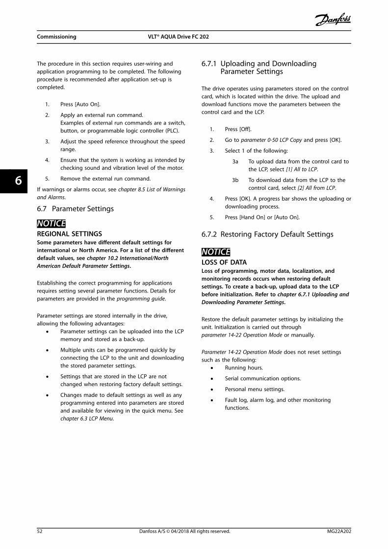
The procedure in this section requires user-wiring andapplication programming to be completed. The followingprocedure is recommended after application set-up iscompleted.
1. Press [Auto On].
2. Apply an external run command.Examples of external run commands are a switch,button, or programmable logic controller (PLC).
3. Adjust the speed reference throughout the speedrange.
4. Ensure that the system is working as intended bychecking sound and vibration level of the motor.
5. Remove the external run command.
If warnings or alarms occur, see chapter 8.5 List of Warningsand Alarms.
6.7 Parameter Settings
NOTICEREGIONAL SETTINGSSome parameters have different default settings forinternational or North America. For a list of the differentdefault values, see chapter 10.2 International/NorthAmerican Default Parameter Settings.
Establishing the correct programming for applicationsrequires setting several parameter functions. Details forparameters are provided in the programming guide.
Parameter settings are stored internally in the drive,allowing the following advantages:
• Parameter settings can be uploaded into the LCPmemory and stored as a back-up.
• Multiple units can be programmed quickly byconnecting the LCP to the unit and downloadingthe stored parameter settings.
• Settings that are stored in the LCP are notchanged when restoring factory default settings.
• Changes made to default settings as well as anyprogramming entered into parameters are storedand available for viewing in the quick menu. See chapter 6.3 LCP Menu.
6.7.1 Uploading and DownloadingParameter Settings
The drive operates using parameters stored on the controlcard, which is located within the drive. The upload anddownload functions move the parameters between thecontrol card and the LCP.
1. Press [Off].
2. Go to parameter 0-50 LCP Copy and press [OK].
3. Select 1 of the following:
3a To upload data from the control card tothe LCP, select [1] All to LCP.
3b To download data from the LCP to thecontrol card, select [2] All from LCP.
4. Press [OK]. A progress bar shows the uploading ordownloading process.
5. Press [Hand On] or [Auto On].
6.7.2 Restoring Factory Default Settings
NOTICELOSS OF DATALoss of programming, motor data, localization, andmonitoring records occurs when restoring defaultsettings. To create a back-up, upload data to the LCPbefore initialization. Refer to chapter 6.7.1 Uploading andDownloading Parameter Settings.
Restore the default parameter settings by initializing theunit. Initialization is carried out throughparameter 14-22 Operation Mode or manually.
Parameter 14-22 Operation Mode does not reset settingssuch as the following:
• Running hours.
• Serial communication options.
• Personal menu settings.
• Fault log, alarm log, and other monitoringfunctions.
Commissioning VLT® AQUA Drive FC 202
52 Danfoss A/S © 04/2018 All rights reserved. MG22A202
66

Recommended initialization1. Press [Main Menu] twice to access parameters.
2. Go to parameter 14-22 Operation Mode andpress [OK].
3. Scroll to Initialization and press [OK].
4. Remove power to the unit and wait for thedisplay to turn off.
5. Apply power to the unit. Default parametersettings are restored during start-up. Start-uptakes slightly longer than normal.
6. After alarm 80, Drive initialized to default valueappears, press [Reset].
Manual initializationManual initialization resets all factory settings except forthe following:
• Parameter 15-00 Operating Hours.
• Parameter 15-03 Power Up's.
• Parameter 15-04 Over Temp's.
• Parameter 15-05 Over Volt's.
To perform manual initialization:1. Remove power to the unit and wait for the
display to turn off.
2. Press and hold [Status], [Main Menu], and [OK]simultaneously while applying power to the unit(approximately 5 s or until an audible clicksounds and the fan starts). Start-up takes slightlylonger than normal.
Commissioning Operating Guide
MG22A202 Danfoss A/S © 04/2018 All rights reserved. 53
6 6

7 Wiring Configuration Examples
The examples in this section are intended as a quickreference for common applications.
• Parameter settings are the regional default valuesunless otherwise indicated (selected inparameter 0-03 Regional Settings).
• Parameters associated with the terminals andtheir settings are shown next to the drawings.
• Required switch settings for analog terminals A53or A54 are also shown.
NOTICEWhen not using the optional STO feature, a jumper wireis required between terminal 12 (or 13) and terminal 37for the drive to operate with factory defaultprogramming values.
7.1 Wiring for Open-loop Speed Control
Parameters
+10 V
A IN
A IN
COM
A OUT
COM
50
53
54
55
42
39
A53
U - I
0 – 10 V
+
-
e30b
b92
6.11FC
Function Setting
Parameter 6-10 Terminal 53 Low Voltage
0.07 V*
Parameter 6-11 Terminal 53 High Voltage
10 V*
Parameter 6-14 Terminal 53 Low Ref./Feedb. Value
0 Hz
Parameter 6-15 Terminal 53 High Ref./Feedb. Value
50 Hz
* = Default value
Notes/comments:Assumptions are 0 V DC input= 0 Hz speed and 10 V DCinput = 50 Hz speed.
Table 7.1 Analog Speed Reference (Voltage)
Parameters
+10 V
A IN
A IN
COM
A OUT
COM
50
53
54
55
42
39
+
-
FC
e30b
b92
7.11
A53
U - I
4 - 20mA
Function Setting
Parameter 6-12 Terminal53 Low Current
4 mA*
Parameter 6-13 Terminal53 High Current
20 mA*
Parameter 6-14 Terminal53 Low Ref./Feedb.Value
0 Hz
Parameter 6-15 Terminal53 High Ref./Feedb.Value
50 Hz
* = Default value
Notes/comments:Assumptions are 4 mA input =0 Hz speed and 20 mA input =50 Hz speed.
Table 7.2 Analog Speed Reference (Current)
Parameters
+10 V
A IN
A IN
COM
A OUT
COM
50
53
54
55
42
39
A53
U - I
≈ 5kΩ
e30b
b68
3.11FC
Function Setting
Parameter 6-12 Terminal53 Low Current
4 mA*
Parameter 6-13 Terminal53 High Current
20 mA*
Parameter 6-14 Terminal53 Low Ref./Feedb.Value
0 Hz
Parameter 6-15 Terminal53 High Ref./Feedb.Value
50 Hz
* = Default value
Notes/comments:Assumptions are 0 V DC input= 0 RPM speed and 10 V DCinput = 1500 RPM speed.
Table 7.3 Speed Reference (Using a Manual Potentiometer)
Wiring Configuration Exampl... VLT® AQUA Drive FC 202
54 Danfoss A/S © 04/2018 All rights reserved. MG22A202
77

Parameters
FC
+24 V
+24 V
D IN
D IN
D IN
COM
D IN
D IN
D IN
D IN
12
13
18
19
20
27
29
32
33
37
e30b
b80
4.12
Function Setting
Parameter 5-10 Terminal 18 Digital Input
[8] Start*
Parameter 5-12 Terminal 27 Digital Input
[19]Freeze
Reference
Parameter 5-13 Terminal 29 Digital Input
[21]Speed Up
Parameter 5-14 Terminal 32 Digital Input
[22]SpeedDown
* = Default value
Notes/comments:
Table 7.4 Speed Up/Speed Down13
0BB8
40.1
2Speed
Reference
Start (18)
Freeze ref (27)
Speed up (29)
Speed down (32)
Illustration 7.1 Speed Up/Speed Down
7.2 Wiring for Start/Stop
Parameters
FC
+24 V
+24 V
D IN
D IN
D IN
COM
D IN
D IN
D IN
D IN
+10
A IN
A IN
COM
A OUT
COM
12
13
18
19
20
27
29
32
33
37
50
53
54
55
42
39
130B
B802
.10 Function Setting
Parameter 5-10 Terminal 18Digital Input
[8] Start*
Parameter 5-12 Terminal 27Digital Input
[0] Nooperation
Parameter 5-19 Terminal 37 SafeStop
[1] Safe StopAlarm
* = Default value
Notes/comments:If parameter 5-12 Terminal 27Digital Input is set to [0] Nooperation, a jumper wire toterminal 27 is not needed.
Table 7.5 Start/Stop Command with Safe Torque Off Option
130B
B805
.12
Speed
Start/Stop (18)
Illustration 7.2 Start/Stop Command with Safe Torque Off
Wiring Configuration Exampl... Operating Guide
MG22A202 Danfoss A/S © 04/2018 All rights reserved. 55
7 7

Parameters
FC
+24 V
+24 V
D IN
D IN
D IN
COM
D IN
D IN
D IN
D IN
+10 V
A IN
A IN
COM
A OUT
COM
12
13
18
19
20
27
29
32
33
37
50
53
54
55
42
39
130B
B803
.10
Function Setting
Parameter 5-10 Terminal 18Digital Input
[9] LatchedStart
Parameter 5-12 Terminal 27Digital Input
[6] Stop Inverse
* = Default value
Notes/comments:
Table 7.6 Pulse Start/Stop
Speed
130B
B806
.10
Latched Start (18)
Stop Inverse (27)
Illustration 7.3 Latched Start/Stop Inverse
Parameters
FC
+24 V
+24 V
D IN
D IN
D IN
COM
D IN
D IN
D IN
+10 VA IN
A IN
COM
A OUT
COM
12
13
18
19
20
27
29
32
33
50
53
54
55
42
39
130B
B934
.11
Function Setting
Parameter 5-10 Terminal 18Digital Input
[8] Start
Parameter 5-11 Terminal 19Digital Input
[10]Reversing*
Parameter 5-12 Terminal 27Digital Input
[0] Nooperation
Parameter 5-14 Terminal 32Digital Input
[16] Preset refbit 0
Parameter 5-15 Terminal 33Digital Input
[17] Preset refbit 1
Parameter 3-10 PresetReference
Preset ref. 0Preset ref. 1Preset ref. 2Preset ref. 3
25%50%75%
100%
* = Default value
Notes/comments:
Table 7.7 Start/Stop with Reversing and 4 Preset Speeds
7.3 Wiring for External Alarm Reset Parameters
FC
+24 V
+24 V
D IN
D IN
D IN
COM
D IN
D IN
D IN
D IN
+10 VA IN
A IN
COM
A OUT
COM
12
13
18
19
20
27
29
32
33
37
50
53
54
55
42
39
130B
B928
.11
Function Setting
Parameter 5-11 Terminal 19Digital Input
[1] Reset
* = Default value
Notes/comments:
Table 7.8 External Alarm Reset
Wiring Configuration Exampl... VLT® AQUA Drive FC 202
56 Danfoss A/S © 04/2018 All rights reserved. MG22A202
77

7.4 Wiring for a Motor Thermistor
WARNINGTHERMISTOR INSULATIONRisk of personal injury or equipment damage.
• To meet PELV insulation requirements, use onlythermistors with reinforced or doubleinsulation.
Parameters
130B
B686
.12
VLT
+24 V
+24 V
D IN
D IN
D IN
COM
D IN
D IN
D IN
+10 VA IN
A IN
COM
A OUT
COM
12
13
18
19
20
27
29
32
33
50
53
54
55
42
39
A53
U - I
D IN 37
Function Setting
Parameter 1-90 Motor ThermalProtection
[2] Thermistortrip
Parameter 1-93 ThermistorResource
[1] Analoginput 53
* = Default value
Notes/comments:If only a warning is desired, setparameter 1-90 Motor ThermalProtection to [1] Thermistorwarning.
Table 7.9 Motor Thermistor
7.5 Wiring for Regeneration
Parameters
FC
+24 V
+24 V
D IN
D IN
D IN
COM
D IN
D IN
D IN
D IN
+10 VA IN
A IN
COM
A OUT
COM
12
13
18
19
20
27
29
32
33
37
50
53
54
55
42
39
130B
D66
7.11
Function Setting
Parameter 1-90 Motor ThermalProtection
100%*
* = Default value
Notes/comments:To disable regeneration,decrease parameter 1-90 MotorThermal Protection to 0%. If theapplication uses motor brakepower and regeneration is notenabled, the unit trips.
Table 7.10 Regeneration
Wiring Configuration Exampl... Operating Guide
MG22A202 Danfoss A/S © 04/2018 All rights reserved. 57
7 7

8 Maintenance, Diagnostics, and Troubleshooting
8.1 Maintenance and Service
This chapter includes:• Maintenance and service guidelines.
• Status messages.
• Warnings and alarms.
• Basic troubleshooting.
Under normal operating conditions and load profiles, thedrive is maintenance-free throughout its designed lifetime.To prevent breakdown, danger, and damage, examine thedrive at regular intervals depending on the operatingconditions. Replace worn or damaged parts with originalspare parts or standard parts. For service and support, referto www.danfoss.com/en/service-and-support/.
WARNINGUNINTENDED STARTWhen the drive is connected to AC mains, DC supply, orload sharing, the motor can start at any time.Unintended start during programming, service, or repairwork can result in death, serious injury, or propertydamage. The motor can start with an external switch, afieldbus command, an input reference signal from theLCP or LOP, via remote operation using MCT 10 Set-upSoftware, or after a cleared fault condition.
To prevent unintended motor start:• Press [Off/Reset] on the LCP before
programming parameters.
• Disconnect the drive from the mains.
• Completely wire and assemble the drive, motor,and any driven equipment before connectingthe drive to AC mains, DC supply, or loadsharing.
8.2 Heat Sink Access Panel
The drive can be ordered with an optional access panel inthe back of the unit. This access panel provides access tothe heat sink and allows the heat sink to be cleaned of anydust buildup.
8.2.1 Removing the Heat Sink Access Panel
NOTICEDAMAGE TO HEAT SINKUsing fasteners that are longer than those originallysupplied with the heat sink panel can damage the heatsink cooling fins.
1. Remove power from the drive and wait 40minutes for the capacitors to dischargecompletely. Refer to chapter 2 Safety.
2. Position the drive so that the back of the drive isfully accessible.
3. Remove the 8 M5 fasteners securing the accesspanel to the back of the enclosure using a 3 mmhex bit.
4. Inspect the leading edge of the heat sink fordamage or debris.
5. Remove material or debris with a vacuum.
6. Reinstall the panel and secure it to the back ofthe enclosure with the 8 fasteners. Tighten thefasteners according to chapter 9.10.1 FastenerTorque Ratings.
130B
F210
.10
Illustration 8.1 Heat Sink Access Panel Removed from the Rearof the Drive
Maintenance, Diagnostics, a... VLT® AQUA Drive FC 202
58 Danfoss A/S © 04/2018 All rights reserved. MG22A202
88

8.3 Status Messages
When the drive is in status mode, status messagesautomatically appear in the bottom line of the LCP display.Refer to Illustration 8.2. Status messages are defined inTable 8.1 – Table 8.3.
Status799RPM 7.83A 36.4kW
0.000
53.2%
1(1)
AutoHandO
RemoteLocal
RampingStopRunningJogging...Stand-by
130B
B037
.11
1
2
3
1 Where the stop/start command originates. Refer to Table 8.1.
2 Where the speed control originates. Refer to Table 8.2.
3 Provides the drive status. Refer to Table 8.3.
Illustration 8.2 Status Display
NOTICEIn auto/remote mode, the drive requires externalcommands to execute functions.
Table 8.1 to Table 8.3 define the meaning of the shownstatus messages.
Off The drive does not react to any control signaluntil [Auto On] or [Hand On] is pressed.
Auto The start/stop commands are sent via thecontrol terminals and/or the serial communi-cation.
Hand The navigation keys on the LCP can be usedto control the drive. Stop commands, reset,reversing, DC brake, and other signals appliedto the control terminals override local control.
Table 8.1 Operating Mode
Remote The speed reference is given from
• External signals.
• Serial communication.
• Internal preset references.
Local The drive uses reference values from the LCP.
Table 8.2 Reference Site
AC brake AC brake was selected in parameter 2-10 BrakeFunction. The AC brake overmagnetizes themotor to achieve a controlled slowdown.
AMA finish OK Automatic motor adaptation (AMA) wascarried out successfully.
AMA ready AMA is ready to start. To start, press [HandOn].
AMA running AMA process is in progress.
Braking The brake chopper is in operation. The brakeresistor absorbs the generative energy.
Braking max. The brake chopper is in operation. The powerlimit for the brake resistor defined inparameter 2-12 Brake Power Limit (kW) hasbeen reached.
Coast • [2] Coast inverse was selected as a functionfor a digital input (parameter group 5-1*Digital Inputs). The corresponding terminalis not connected.
• Coast activated by serial communication.
Ctrl. ramp-down [1] Ctrl. ramp-down was selected inparameter 14-10 Mains Failure.
• The mains voltage is below the value setin parameter 14-11 Mains Voltage at MainsFault at mains fault.
• The drive ramps down the motor using acontrolled ramp down.
Current high The drive output current is above the limit setin parameter 4-51 Warning Current High.
Current low The drive output current is below the limit setin parameter 4-52 Warning Speed Low.
DC hold DC hold is selected in parameter 1-80 Functionat Stop and a stop command is active. Themotor is held by a DC current set inparameter 2-00 DC Hold Current.
DC stop The motor is held with a DC current(parameter 2-01 DC Brake Current) for aspecified time (parameter 2-02 DC BrakingTime).
• DC brake is activated in parameter 2-03 DCBrake Cut In Speed [RPM] and a stopcommand is active.
• DC brake (inverse) is selected as a functionfor a digital input (parameter group 5-1*Digital Inputs). The corresponding terminalis not active.
• The DC brake is activated via serialcommunication.
Feedback high The sum of all active feedbacks is above thefeedback limit set in parameter 4-57 WarningFeedback High.
Feedback low The sum of all active feedbacks is below thefeedback limit set in parameter 4-56 WarningFeedback Low.
Maintenance, Diagnostics, a... Operating Guide
MG22A202 Danfoss A/S © 04/2018 All rights reserved. 59
8 8

Freeze output The remote reference is active, which holdsthe present speed.
• [20] Freeze Output was selected as afunction for a digital input (parametergroup 5-1* Digital Inputs). Thecorresponding terminal is active. Speedcontrol is only possible via the terminalfunctions speed up and speed down.
• Hold ramp is activated via serial communi-cation.
Freeze outputrequest
A freeze output command has been given, butthe motor remains stopped until a runpermissive signal is received.
Freeze ref. [19] Freeze Reference was selected as afunction for a digital input (parameter group5-1* Digital Inputs). The corresponding terminalis active. The drive saves the actual reference.Changing the reference is now only possiblevia terminal functions speed up and speeddown.
Jog request A jog command has been given, but themotor is stopped until a run permissive signalis received via a digital input.
Jogging The motor is running as programmed inparameter 3-19 Jog Speed [RPM].
• [14] Jog was selected as function for adigital input (parameter group 5-1* DigitalInputs). The corresponding terminal (forexample, terminal 29) is active.
• The jog function is activated via the serialcommunication.
• The jog function was selected as a reactionfor a monitoring function (for example, Nosignal). The monitoring function is active.
Motor check In parameter 1-80 Function at Stop, [2] MotorCheck was selected. A stop command is active.To ensure that a motor is connected to thedrive, a permanent test current is applied tothe motor.
OVC control Overvoltage control was activated inparameter 2-17 Over-voltage Control, [2]Enabled. The connected motor is supplyingthe drive with generative energy. Theovervoltage control adjusts the V/Hz ratio torun the motor in controlled mode and toprevent the drive from tripping.
Power unit off (For drives with a 24 V DC external supplyinstalled only.) Mains supply to the drive isremoved, but the control card is supplied bythe 24 V DC external supply.
Protection md Protection mode is active. The unit hasdetected a critical status (an overcurrent orovervoltage).
• To avoid tripping, the switching frequencyis reduced to 1500 kHz ifparameter 14-55 Output Filter is set to [2]Sine-Wave Filter Fixed. Otherwise, theswitching frequency is reduced to 1000 Hz.
• If possible, protection mode ends afterapproximately 10 s.
• Protection mode can be restricted inparameter 14-26 Trip Delay at Inverter Fault.
QStop The motor is decelerating usingparameter 3-81 Quick Stop Ramp Time.
• [4] Quick stop inverse was selected as afunction for a digital input (parametergroup 5-1* Digital Inputs). Thecorresponding terminal is not active.
• The quick stop function was activated viaserial communication.
Ramping The motor is accelerating/decelerating usingthe active ramp up/down. The reference, alimit value, or a standstill is not yet reached.
Ref. high The sum of all active references is above thereference limit set in parameter 4-55 WarningReference High.
Ref. low The sum of all active references is below thereference limit set in parameter 4-54 WarningReference Low.
Run on ref. The drive is running in the reference range.The feedback value matches the setpointvalue.
Run request A start command has been given, but themotor is stopped until a run permissive signalis received via digital input.
Running The drive is driving the motor.
Sleep mode The energy saving function is enabled. Thisfunction being enabled means that now themotor has stopped, but that it restartsautomatically when required.
Speed high The motor speed is above the value set inparameter 4-53 Warning Speed High.
Speed low The motor speed is below the value set inparameter 4-52 Warning Speed Low.
Standby In auto-on mode, the drive starts the motorwith a start signal from a digital input or serialcommunication.
Start delay In parameter 1-71 Start Delay, a delay startingtime was set. A start command is activatedand the motor starts after the start delay timeexpires.
Maintenance, Diagnostics, a... VLT® AQUA Drive FC 202
60 Danfoss A/S © 04/2018 All rights reserved. MG22A202
88

Start fwd/rev [12] Enable Start Forward and [13] Enable StartReverse were selected as functions for 2different digital inputs (parameter group 5-1*Digital Inputs). The motor starts in forward orreverse depending on which correspondingterminal is activated.
Stop The drive has received a stop command from1 of the following:
• LCP.
• Digital input.
• Serial communication.
Trip An alarm occurred and the motor is stopped.Once the cause of the alarm is cleared, resetthe drive using 1 of the following:
• Pressing [Reset].
• Remotely by control terminals.
• Via serial communication.
Pressing [Reset] or remotely by controlterminals or via serial communication.
Trip lock An alarm occurred and the motor is stopped.Once the cause of the alarm is cleared, cyclepower to the drive. Reset the drive manuallyby 1 of the following:
• Pressing [Reset].
• Remotely by control terminals.
• Via serial communication.
Table 8.3 Operation Status
8.4 Warning and Alarm Types
The drive software issues warnings and alarms to assist indiagnosing issues. The warning or alarm number appearsin the LCP.
WarningA warning indicates the drive has encountered anabnormal operating condition that leads to an alarm. Awarning stops when the abnormal condition is removed orresolved.
AlarmAn alarm indicates a fault that requires immediateattention. The fault always triggers a trip or trip lock. Resetthe drive after an alarm.Reset the drive in any of 4 ways:
• Press [Reset]/[Off/Reset].
• Digital reset input command.
• Serial communication reset input command.
• Auto reset.
TripWhen tripping, the drive suspends operation to preventdamage to the drive and other equipment. When a tripoccurs, the motor coasts to a stop. The drive logiccontinues to operate and monitor the drive status. Afterthe fault condition is remedied, the drive is ready for areset.
Trip lockWhen trip locking, the drive suspends operation to preventdamage to the drive and other equipment. When a triplock occurs, the motor coasts to a stop. The drive logiccontinues to operate and monitor the drive status. Thedrive starts a trip lock only when serious faults occur thatcan damage the drive or other equipment. After the faultsare fixed, cycle the input power before resetting the drive.
Warning and alarm displays
• A warning is shown in the LCP along with thewarning number.
• An alarm flashes along with the alarm number.
130B
P086
.12
Status0.0Hz 0.000kW 0.00A
0.0Hz0
Earth Fault [A14]Auto Remote Trip
1(1)
Illustration 8.3 Alarm Example
In addition to the text and alarm code in the LCP, there are3 status indicator lights.
Back
CancelInfoOKOn
Alarm
Warn.
130B
B467
.11
Warning indicator light Alarm indicator light
Warning On Off
Alarm Off On (flashing)
Trip lock On On (flashing)
Illustration 8.4 Status Indicator Lights
Maintenance, Diagnostics, a... Operating Guide
MG22A202 Danfoss A/S © 04/2018 All rights reserved. 61
8 8

8.5 List of Warnings and Alarms
The following warning and alarm information defines eachwarning or alarm condition, provides the probable causefor the condition, and details a remedy or troubleshootingprocedure.
WARNING 1, 10 Volts lowThe control card voltage is less than 10 V from terminal 50.Remove some of the load from terminal 50, as the 10 Vsupply is overloaded. Maximum 15 mA or minimum 590 Ω.
A short circuit in a connected potentiometer or incorrectwiring of the potentiometer can cause this condition.
Troubleshooting• Remove the wiring from terminal 50. If the
warning clears, the problem is with the wiring. Ifthe warning does not clear, replace the controlcard.
WARNING/ALARM 2, Live zero errorThis warning or alarm only appears if programmed inparameter 6-01 Live Zero Timeout Function. The signal on 1of the analog inputs is less than 50% of the minimumvalue programmed for that input. Broken wiring or a faultydevice sending the signal can cause this condition.
Troubleshooting• Check connections on all analog mains terminals.
- Control card terminals 53 and 54 forsignals, terminal 55 common.
- VLT® General Purpose I/O MCB 101terminals 11 and 12 for signals, terminal10 common.
- VLT® Analog I/O Option MCB 109terminals 1, 3, and 5 for signals,terminals 2, 4, and 6 common.
• Check that the drive programming and switchsettings match the analog signal type.
• Perform an input terminal signal test.
WARNING/ALARM 3, No motorNo motor has been connected to the output of the drive.
WARNING/ALARM 4, Mains phase lossA phase is missing on the supply side, or the mainsvoltage imbalance is too high. This message also appearsfor a fault in the input rectifier. Options are programmed inparameter 14-12 Function at Mains Imbalance.
Troubleshooting• Check the supply voltage and supply currents to
the drive.
WARNING 5, DC link voltage highThe DC-link voltage (DC) is higher than the high-voltagewarning limit. The limit depends on the drive voltagerating. The unit is still active.
WARNING 6, DC link voltage lowThe DC-link voltage (DC) is lower than the low-voltagewarning limit. The limit depends on the drive voltagerating. The unit is still active.
WARNING/ALARM 7, DC overvoltageIf the DC-link voltage exceeds the limit, the drive trips aftera time.
Troubleshooting• Extend the ramp time.
• Change the ramp type.
• Increase parameter 14-26 Trip Delay at InverterFault.
• Check that the supply voltage matches the activefront-end drive voltage.
• Perform input voltage test.
WARNING/ALARM 8, DC under voltageIf the DC-link voltage drops below the undervoltage limit,the drive checks for 24 V DC back-up supply. If no 24 V DCback-up supply is connected, the drive trips after a fixedtime delay. The time delay varies with unit size.
Troubleshooting• Check that the supply voltage matches the drive
voltage.
• Perform an input voltage test.
• Perform a soft-charge circuit test.
WARNING/ALARM 9, Inverter overloadThe drive has run with more than 100% overload for toolong and is about to cut out. The counter for electronicthermal inverter protection issues a warning at 98% andtrips at 100% with an alarm. The drive cannot be resetuntil the counter is below 90%.
Troubleshooting• Compare the output current shown on the LCP
with the drive rated current.
• Compare the output current shown on the LCPwith the measured motor current.
• Show the thermal drive load on the LCP andmonitor the value. When running above the drivecontinuous current rating, the counter increases.When running below the drive continuouscurrent rating, the counter decreases.
WARNING/ALARM 10, Motor overload temperatureAccording to the electronic thermal protection (ETR), themotor is too hot.
Select 1 of these options:• The drive issues a warning or an alarm when the
counter is >90% if parameter 1-90 Motor ThermalProtection is set to warning options.
• The drive trips when the counter reaches 100% ifparameter 1-90 Motor Thermal Protection is set totrip options.
Maintenance, Diagnostics, a... VLT® AQUA Drive FC 202
62 Danfoss A/S © 04/2018 All rights reserved. MG22A202
88

The fault occurs when the motor runs with more than100% overload for too long.
Troubleshooting• Check for motor overheating.
• Check if the motor is mechanically overloaded.
• Check that the motor current set inparameter 1-24 Motor Current is correct.
• Ensure that the motor data in parameters 1-20 to1-25 is set correctly.
• If an external fan is in use, check that it isselected in parameter 1-91 Motor External Fan.
• Running AMA in parameter 1-29 Automatic MotorAdaptation (AMA) tunes the drive to the motormore accurately and reduces thermal loading.
WARNING/ALARM 11, Motor thermistor overtempCheck whether the thermistor is disconnected. Selectwhether the drive issues a warning or an alarm inparameter 1-90 Motor Thermal Protection.
Troubleshooting• Check for motor overheating.
• Check if the motor is mechanically overloaded.
• When using terminal 53 or 54, check that thethermistor is connected correctly between eitherterminal 53 or 54 (analog voltage input) andterminal 50 (+10 V supply). Also check that theterminal switch for 53 or 54 is set for voltage.Check that parameter 1-93 Thermistor Resourceselects terminal 53 or 54.
• When using terminal 18, 19, 31, 32, or 33 (digitalinputs), check that the thermistor is connectedcorrectly between the digital input terminal used(digital input PNP only) and terminal 50. Selectthe terminal to use in parameter 1-93 ThermistorResource.
WARNING/ALARM 12, Torque limitThe torque has exceeded the value inparameter 4-16 Torque Limit Motor Mode or the value inparameter 4-17 Torque Limit Generator Mode.Parameter 14-25 Trip Delay at Torque Limit can change thiswarning from a warning-only condition to a warningfollowed by an alarm.
Troubleshooting• If the motor torque limit is exceeded during
ramp-up, extend the ramp-up time.
• If the generator torque limit is exceeded duringramp-down, extend the ramp-down time.
• If torque limit occurs while running, increase thetorque limit. Make sure that the system canoperate safely at a higher torque.
• Check the application for excessive current drawon the motor.
WARNING/ALARM 13, Over currentThe inverter peak current limit (approximately 200% of therated current) is exceeded. The warning lasts approximately1.5 s, then the drive trips and issues an alarm. Shockloading or quick acceleration with high-inertia loads cancause this fault. If the acceleration during ramp-up is quick,the fault can also appear after kinetic back-up.If extended mechanical brake control is selected, a trip canbe reset externally.
Troubleshooting• Remove the power and check if the motor shaft
can be turned.
• Check that the motor size matches the drive.
• Check that the motor data is correct inparameters 1-20 to 1-25.
ALARM 14, Earth (ground) faultThere is current from the output phase to ground, either inthe cable between the drive and the motor, or in themotor itself. The current transducers detect the groundfault by measuring current going out from the drive andcurrent going into the drive from the motor. Ground faultis issued if the deviation of the 2 currents is too large. Thecurrent going out of the drive must be the same as thecurrent going into the drive.
Troubleshooting• Remove power to the drive and repair the ground
fault.
• Check for ground faults in the motor bymeasuring the resistance to ground of the motorcables and the motor with a megohmmeter.
• Reset any potential individual offset in the 3current transducers in the drive. Perform themanual initialization or perform a complete AMA.This method is most relevant after changing thepower card.
ALARM 15, Hardware mismatchA fitted option is not operational with the present controlcard hardware or software.
Record the value of the following parameters and contactDanfoss.
• Parameter 15-40 FC Type.
• Parameter 15-41 Power Section.
• Parameter 15-42 Voltage.
• Parameter 15-43 Software Version.
• Parameter 15-45 Actual Typecode String.
• Parameter 15-49 SW ID Control Card.
• Parameter 15-50 SW ID Power Card.
• Parameter 15-60 Option Mounted.
• Parameter 15-61 Option SW Version (for eachoption slot).
Maintenance, Diagnostics, a... Operating Guide
MG22A202 Danfoss A/S © 04/2018 All rights reserved. 63
8 8

ALARM 16, Short circuitThere is short-circuiting in the motor or motor wiring.
Troubleshooting• Remove the power to the drive and repair the
short circuit.
WARNINGHIGH VOLTAGEDrives contain high voltage when connected to AC mainsinput, DC supply, or load sharing. Failure to use qualifiedpersonnel to install, start up, and maintain the drive canresult in death or serious injury.
• Disconnect power before proceeding.
WARNING/ALARM 17, Control word timeoutThere is no communication to the drive.The warning is only active when parameter 8-04 ControlWord Timeout Function is NOT set to [0] Off.If parameter 8-04 Control Word Timeout Function is set to [5]Stop and trip, a warning appears, and the drive rampsdown to a stop and shows an alarm.
Troubleshooting• Check the connections on the serial communi-
cation cable.
• Increase parameter 8-03 Control Word TimeoutTime.
• Check the operation of the communicationequipment.
• Verify that proper EMC installation wasperformed.
WARNING/ALARM 20, Temp. input errorThe temperature sensor is not connected.
WARNING/ALARM 21, Parameter errorThe parameter is out of range. The parameter number isshown in the display.
Troubleshooting• Set the affected parameter to a valid value.
WARNING 22, Hoist mechanical brake0 = The torque reference was not reached before timeout.1 = There was no brake feedback before the timeout.
WARNING 23, Internal fan faultThe fan warning function is a protective function thatchecks if the fan is running/mounted. The fan warning canbe disabled in parameter 14-53 Fan Monitor ([0] Disabled).
There is a feedback sensor mounted in the fan. If the fan iscommanded to run and there is no feedback from thesensor, this alarm appears. This alarm also shows if there isa communication error between the fan power card andthe control card.
Check the alarm log (see chapter 3.6 Local Control Panel(LCP)) for the report value associated with this warning.
If the report value is 2, there is a hardware problem with 1of the fans. If the report value is 12, there is a communi-cation problem between the fan power card and thecontrol card.
Fan troubleshooting• Cycle power to the drive and check that the fan
operates briefly at start-up.
• Check for proper fan operation. Use parametergroup 43-** Unit Readouts to show the speed ofeach fan.
Fan power card troubleshooting• Check the wiring between the fan power card
and the control card.
• Fan power card may need to be replaced.
• Control card may need to be replaced.
WARNING 24, External fan faultThe fan warning function is a protective function thatchecks if the fan is running/mounted. The fan warning canbe disabled in parameter 14-53 Fan Monitor ([0] Disabled).
There is a feedback sensor mounted in the fan. If the fan iscommanded to run and there is no feedback from thesensor, this alarm appears. This alarm also shows if there isa communication error between the power card and thecontrol card.
Check the alarm log (see chapter 3.6 Local Control Panel(LCP)) for the report value associated with this warning.
If the report value is 1, there is a hardware problem with 1of the fans. If the report value is 11, there is a communi-cation problem between the power card and the controlcard.
Fan troubleshooting• Cycle power to the drive and check that the fan
operates briefly at start-up.
• Check for proper fan operation. Use parametergroup 43-** Unit Readouts to show the speed ofeach fan.
Power card troubleshooting• Check the wiring between the power card and
the control card.
• Power card may need to be replaced.
• Control card may need to be replaced.
WARNING 25, Brake resistor short circuitThe brake resistor is monitored during operation. If a shortcircuit occurs, the brake function is disabled and thewarning appears. The drive is still operational, but withoutthe brake function.
Troubleshooting• Remove the power to the drive and replace the
brake resistor (refer to parameter 2-15 BrakeCheck).
Maintenance, Diagnostics, a... VLT® AQUA Drive FC 202
64 Danfoss A/S © 04/2018 All rights reserved. MG22A202
88

WARNING/ALARM 26, Brake resistor power limitThe power transmitted to the brake resistor is calculated asa mean value over the last 120 s of run-time. Thecalculation is based on the DC-link voltage and the brakeresistor value set in parameter 2-16 AC brake Max. Current.The warning is active when the dissipated braking poweris higher than 90% of the brake resistor power. If option [2]Trip is selected in parameter 2-13 Brake Power Monitoring,the drive trips when the dissipated braking power reaches100%.
WARNING/ALARM 27, Brake chopper faultThe brake transistor is monitored during operation, and if ashort circuit occurs, the brake function is disabled, and awarning is issued. The drive is still operational, but sincethe brake transistor has short-circuited, substantial poweris transmitted to the brake resistor, even if it is inactive.
Troubleshooting• Remove power to the drive and remove the brake
resistor.
WARNING/ALARM 28, Brake check failedThe brake resistor is not connected or not working.
Troubleshooting• Check parameter 2-15 Brake Check.
ALARM 29, Heat sink tempThe maximum temperature of the heat sink has beenexceeded. This alarm is based on the temperaturemeasured by the heat sink sensor mounted inside the IGBTmodules. The temperature fault does not reset until thetemperature drops below a defined heat sink temperature.The trip and reset points are different based on the drivepower size.
Troubleshooting• Check for the following conditions:
- Ambient temperature too high.
- Motor cable too long.
- Incorrect airflow clearance above andbelow the drive.
- Blocked airflow around the drive.
- Damaged heat sink fan.
- Dirty heat sink.
• Check fan resistance.
• Check soft charge fuses.
• Check IGBT thermal.
ALARM 30, Motor phase U missingMotor phase U between the drive and the motor ismissing.
WARNINGHIGH VOLTAGEDrives contain high voltage when connected to AC mainsinput, DC supply, or load sharing. Failure to performinstallation, start-up, and maintenance by qualifiedpersonnel can result in death or serious injury.
• Only qualified personnel must perform instal-lation, start-up, and maintenance.
• Before performing any service or repair work,use an appropriate voltage measuring device tomake sure that there is no remaining voltage onthe drive.
Troubleshooting• Remove the power from the drive and check
motor phase U.
ALARM 31, Motor phase V missingMotor phase V between the drive and the motor ismissing.
WARNINGHIGH VOLTAGEDrives contain high voltage when connected to AC mainsinput, DC supply, or load sharing. Failure to performinstallation, start-up, and maintenance by qualifiedpersonnel can result in death or serious injury.
• Only qualified personnel must perform instal-lation, start-up, and maintenance.
• Before performing any service or repair work,use an appropriate voltage measuring device tomake sure that there is no remaining voltage onthe drive.
Troubleshooting• Remove the power from the drive and check
motor phase V.
ALARM 32, Motor phase W missingMotor phase W between the drive and the motor ismissing.
Maintenance, Diagnostics, a... Operating Guide
MG22A202 Danfoss A/S © 04/2018 All rights reserved. 65
8 8

WARNINGHIGH VOLTAGEDrives contain high voltage when connected to AC mainsinput, DC supply, or load sharing. Failure to performinstallation, start-up, and maintenance by qualifiedpersonnel can result in death or serious injury.
• Only qualified personnel must perform instal-lation, start-up, and maintenance.
• Before performing any service or repair work,use an appropriate voltage measuring device tomake sure that there is no remaining voltage onthe drive.
Troubleshooting• Remove the power from the drive and check
motor phase W.
ALARM 33, Inrush faultToo many power-ups have occurred within a short timeperiod.
Troubleshooting• Let the unit cool to operating temperature.
• Check potential DC-link fault to ground.
WARNING/ALARM 34, Fieldbus communication faultThe fieldbus on the communication option card is notworking.
WARNING/ALARM 35, Option faultAn option alarm is received. The alarm is option-specific.The most likely cause is a power-up or a communicationfault.
WARNING/ALARM 36, Mains failureThis warning/alarm is only active if the supply voltage tothe drive system is lost and parameter 14-10 Mains Failureis not set to option [0] No Function.
• Check the fuses to the drive system and themains supply to the unit.
• Check that mains voltage conforms to productspecifications.
• Check that the following conditions are notpresent:Alarm 307, Excessive THD(V), alarm 321, Voltageimbalance, warning 417, Mains undervoltage, orwarning 418, Mains overvoltage is reported if anyof the listed conditions are true:
- The 3-phase voltage magnitude dropsbelow 25% of the nominal mainsvoltage.
- Any single-phase voltage exceeds 10%of the nominal mains voltage.
- Percent of phase or magnitudeimbalance exceeds 8%.
- Voltage THD exceeds 10%.
ALARM 37, Phase imbalanceThere is a current imbalance between the power units.
ALARM 38, Internal faultWhen an internal fault occurs, a code number defined inTable 8.4 is shown.
Troubleshooting• Cycle power.
• Check that the option is properly installed.
• Check for loose or missing wiring.
It may be necessary to contact the Danfoss supplier orservice department. Note the code number for furthertroubleshooting directions.
Number Text
0 The serial port cannot be initialized. Contact theDanfoss supplier or Danfoss Service Department.
256–259,266, 268
The power EEPROM data is defective or too old.Replace the power card.
512–519 Internal fault. Contact the Danfoss supplier orDanfoss Service Department.
783 Parameter value outside of minimum/maximumlimits.
1024–1284 Internal fault. Contact the Danfoss supplier orDanfoss Service Department.
1299 The option SW in slot A is too old.
1300 The option SW in slot B is too old.
1301 The option SW in slot C0 is too old.
1302 The option SW in slot C1 is too old.
1315 The option SW in slot A is not supported (notallowed).
1316 The option SW in slot B is not supported (notallowed).
1317 The option SW in slot C0 is not supported (notallowed).
1318 The option SW in slot C1 is not supported (notallowed).
1360–2819 Internal fault. Contact the Danfoss supplier orDanfoss Service Department.
2561 Replace control card.
2820 LCP stack overflow.
2821 Serial port overflow.
2822 USB port overflow.
3072–5122 Parameter value is outside its limits.
5123 Option in slot A: Hardware incompatible withcontrol board hardware.
5124 Option in slot B: Hardware incompatible withcontrol board hardware.
5125 Option in slot C0: Hardware incompatible withcontrol board hardware.
5126 Option in slot C1: Hardware incompatible withcontrol board hardware.
Maintenance, Diagnostics, a... VLT® AQUA Drive FC 202
66 Danfoss A/S © 04/2018 All rights reserved. MG22A202
88

Number Text
5127 Illegal option combination (2 options of the samekind mounted, or encoder in E0 and resolver in E1or similar).
5168 Safe stop/safe torque off was detected on acontrol card that does not have safe stop/safetorque off.
5376–65535 Internal fault. Contact the Danfoss supplier orDanfoss Service Department.
Table 8.4 Internal Fault Codes
ALARM 39, Heat sink sensorNo feedback from the heat sink temperature sensor.
The signal from the IGBT thermal sensor is not available onthe power card. The problem could be on the power card,on the gatedrive card, or the ribbon cable between thepower card and gatedrive card.
WARNING 40, Overload of digital output terminal 27Check the load connected to terminal 27 or remove theshort-circuit connection. Check parameter 5-00 Digital I/OMode and parameter 5-01 Terminal 27 Mode.
WARNING 41, Overload of digital output terminal 29Check the load connected to terminal 29 or remove theshort-circuit connection. Also check parameter 5-00 DigitalI/O Mode and parameter 5-02 Terminal 29 Mode.
WARNING 42, Overload of digital output on X30/6 oroverload of digital output on X30/7For terminal X30/6, check the load connected to terminalX30/6 or remove the short-circuit connection. Also checkparameter 5-32 Term X30/6 Digi Out (MCB 101) (VLT®
General Purpose I/O MCB 101).
For terminal X30/7, check the load connected to terminalX30/7 or remove the short-circuit connection. Checkparameter 5-33 Term X30/7 Digi Out (MCB 101) (VLT®
General Purpose I/O MCB 101).
ALARM 43, Ext. supplyVLT® Extended Relay Option MCB 113 is mounted withoutexternal 24 V DC. Either connect a 24 V DC external supplyor specify that no external supply is used viaparameter 14-80 Option Supplied by External 24VDC, [0] No.A change in parameter 14-80 Option Supplied by External24VDC requires a power cycle.
ALARM 45, Earth fault 2Ground fault.
Troubleshooting• Check for proper grounding and loose
connections.
• Check for proper wire size.
• Check the motor cables for short circuits orleakage currents.
ALARM 46, Power card supplyThe supply on the power card is out of range. Anotherreason can be a defective heat sink fan.
There are 3 supplies generated by the switch mode supply(SMPS) on the power card:
• 24 V.
• 5 V.
• ±18 V.
When powered with VLT® 24 V DC Supply MCB 107, onlythe 24 V and 5 V supplies are monitored. When poweredwith 3-phase mains voltage, all 3 supplies are monitored.
Troubleshooting• Check for a defective power card.
• Check for a defective control card.
• Check for a defective option card.
• If a 24 V DC supply is used, verify proper supplypower.
• Check for a defective heat sink fan.
WARNING 47, 24 V supply lowThe supply on the power card is out of range.
There are 3 supplies generated by the switch mode supply(SMPS) on the power card:
• 24 V.
• 5 V.
• ±18 V.
Troubleshooting• Check for a defective power card.
WARNING 48, 1.8 V supply lowThe 1.8 V DC supply used on the control card is outside ofthe allowable limits. The supply is measured on the controlcard.
Troubleshooting• Check for a defective control card.
• If an option card is present, check forovervoltage.
WARNING 49, Speed limitThe warning is shown when the speed is outside of thespecified range in parameter 4-11 Motor Speed Low Limit[RPM] and parameter 4-13 Motor Speed High Limit [RPM].When the speed is below the specified limit inparameter 1-86 Trip Speed Low [RPM] (except when startingor stopping), the drive trips.
ALARM 50, AMA calibration failedContact the Danfoss supplier or Danfoss ServiceDepartment.
ALARM 51, AMA check Unom and Inom
The settings for motor voltage, motor current, and motorpower are wrong.
Troubleshooting• Check the settings in parameters 1-20 to 1-25.
Maintenance, Diagnostics, a... Operating Guide
MG22A202 Danfoss A/S © 04/2018 All rights reserved. 67
8 8
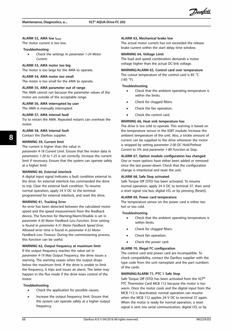
ALARM 52, AMA low Inom
The motor current is too low.
Troubleshooting• Check the settings in parameter 1-24 Motor
Current.
ALARM 53, AMA motor too bigThe motor is too large for the AMA to operate.
ALARM 54, AMA motor too smallThe motor is too small for the AMA to operate.
ALARM 55, AMA parameter out of rangeThe AMA cannot run because the parameter values of themotor are outside of the acceptable range.
ALARM 56, AMA interrupted by userThe AMA is manually interrupted.
ALARM 57, AMA internal faultTry to restart the AMA. Repeated restarts can overheat themotor.
ALARM 58, AMA Internal faultContact the Danfoss supplier.
WARNING 59, Current limitThe current is higher than the value inparameter 4-18 Current Limit. Ensure that the motor data inparameters 1-20 to 1-25 is set correctly. Increase the currentlimit if necessary. Ensure that the system can operate safelyat a higher limit.
WARNING 60, External interlockA digital input signal indicates a fault condition external tothe drive. An external interlock has commanded the driveto trip. Clear the external fault condition. To resumenormal operation, apply 24 V DC to the terminalprogrammed for external interlock, and reset the drive.
WARNING 61, Tracking ErrorAn error has been detected between the calculated motorspeed and the speed measurement from the feedbackdevice. The function for Warning/Alarm/Disable is set inparameter 4-30 Motor Feedback Loss Function. Error settingis found in parameter 4-31 Motor Feedback Speed Error.Allowed error time is found in parameter 4-32 MotorFeedback Loss Timeout. During the commissioning process,this function can be useful.
WARNING 62, Output frequency at maximum limitIf the output frequency reaches the value set inparameter 4-19 Max Output Frequency, the drive issues awarning. The warning ceases when the output dropsbelow the maximum limit. If the drive is unable to limitthe frequency, it trips and issues an alarm. The latter mayhappen in the flux mode if the drive loses control of themotor.
Troubleshooting• Check the application for possible causes.
• Increase the output frequency limit. Ensure thatthe system can operate safely at a higher outputfrequency.
ALARM 63, Mechanical brake lowThe actual motor current has not exceeded the releasebrake current within the start delay time window.
WARNING 64, Voltage LimitThe load and speed combination demands a motorvoltage higher than the actual DC-link voltage.
WARNING/ALARM 65, Control card over temperatureThe cutout temperature of the control card is 85 °C(185 °F).
Troubleshooting• Check that the ambient operating temperature is
within the limits.
• Check for clogged filters.
• Check the fan operation.
• Check the control card.
WARNING 66, Heat sink temperature lowThe drive is too cold to operate. This warning is based onthe temperature sensor in the IGBT module. Increase theambient temperature of the unit. Also, a trickle amount ofcurrent can be supplied to the drive whenever the motoris stopped by setting parameter 2-00 DC Hold/PreheatCurrent to 5% and parameter 1-80 Function at Stop.
ALARM 67, Option module configuration has changedOne or more options have either been added or removedsince the last power-down. Check that the configurationchange is intentional and reset the unit.
ALARM 68, Safe Stop activatedSafe Torque Off (STO) has been activated. To resumenormal operation, apply 24 V DC to terminal 37, then senda reset signal (via bus, digital I/O, or by pressing [Reset]).
ALARM 69, Power card temperatureThe temperature sensor on the power card is either toohot or too cold.
Troubleshooting• Check that the ambient operating temperature is
within limits.
• Check for clogged filters.
• Check fan operation.
• Check the power card.
ALARM 70, Illegal FC configurationThe control card and power card are incompatible. Tocheck compatibility, contact the Danfoss supplier with thetype code from the unit nameplate and the part numbersof the cards.
WARNING/ALARM 71, PTC 1 Safe StopSafe Torque Off (STO) has been activated from the VLT®
PTC Thermistor Card MCB 112 because the motor is toowarm. Once the motor cools and the digital input from theMCB 112 is deactivated, normal operation can resumewhen the MCB 112 applies 24 V DC to terminal 37 again.When the motor is ready for normal operation, a resetsignal is sent (via serial communication, digital I/O, or by
Maintenance, Diagnostics, a... VLT® AQUA Drive FC 202
68 Danfoss A/S © 04/2018 All rights reserved. MG22A202
88

pressing [Reset] on the LCP). If automatic restart isenabled, the motor can start when the fault is cleared.
ALARM 72, Dangerous failureSafe Torque Off (STO) with trip lock. Unexpected signallevels on safe torque off and digital input from the VLT®
PTC Thermistor Card MCB 112.
WARNING 73, Safe Stop auto restartSafe Torque Off (STO). With automatic restart enabled, themotor can start when the fault is cleared.
ALARM 74, PTC ThermistorAlarm related to VLT® PTC Thermistor Card MCB 112. ThePTC is not working.
ALARM 75, Illegal profile sel.Do not write the parameter value while the motor isrunning. Stop the motor before writing the MCO profile toparameter 8-10 Control Word Profile.
WARNING 76, Power unit setupThe required number of power units does not match thedetected number of active power units. When replacing anenclosure size F module, this warning occurs if the power-specific data in the module power card does not matchthe rest of the drive. If the power card connection is lost,the unit also triggers this warning.
Troubleshooting• Confirm that the spare part and its power card
are the correct part number.
• Ensure that the 44-pin cables between the MDCICand power cards are mounted properly.
WARNING 77, Reduced power modeThis warning indicates that the drive is operating inreduced power mode (that is, less than the allowednumber of inverter sections). This warning is generated onpower cycle when the drive is set to run with fewerinverters and remains on.
ALARM 78, Tracking errorThe difference between setpoint value and actual valueexceeds the value in parameter 4-35 Tracking Error.
Troubleshooting• Disable the function or select an alarm/warning
in parameter 4-34 Tracking Error Function.
• Investigate the mechanics around the load andmotor. Check feedback connections from motorencoder to drive.
• Select motor feedback function inparameter 4-30 Motor Feedback Loss Function.
• Adjust the tracking error band inparameter 4-35 Tracking Error andparameter 4-37 Tracking Error Ramping.
ALARM 79, Illegal power section configurationThe scaling card is the incorrect part number or notinstalled. Also, the MK102 connector on the power cardcould not be installed.
ALARM 80, Drive initialised to default valueParameter settings are initialized to default settings after amanual reset. To clear the alarm, reset the unit.
ALARM 81, CSIV corruptCSIV file has syntax errors.
ALARM 82, CSIV parameter errorCSIV failed to initialize a parameter.
ALARM 83, Illegal option combinationThe mounted options are incompatible.
ALARM 84, No safety optionThe safety option was removed without applying a generalreset. Reconnect the safety option.
ALARM 85, Dang fail PBPROFIBUS/PROFIsafe error.
ALARM 88, Option detectionA change in the option layout is detected.Parameter 14-89 Option Detection is set to [0] Frozen config-uration and the option layout has been changed.
• To apply the change, enable option layoutchanges in parameter 14-89 Option Detection.
• Alternatively, restore the correct option configu-ration.
WARNING 89, Mechanical brake slidingThe hoist brake monitor detects a motor speed exceeding10 RPM.
ALARM 90, Feedback monitorCheck the connection to encoder/resolver option and, ifnecessary, replace VLT® Encoder Input MCB 102 or VLT®
Resolver Input MCB 103.
ALARM 91, Analog input 54 wrong settingsSet switch S202 in position OFF (voltage input) when aKTY sensor is connected to analog input terminal 54.
WARNING 98, Clock faultTime is not set or the RTC clock has failed.
Troubleshooting• Reset the clock in parameter 0-70 Date and Time.
ALARM 99, Locked rotorThe rotor is blocked.
WARNING/ALARM 104, Mixing fan faultThe fan is not operating. The fan monitor checks that thefan is spinning at power-up or whenever the mixing fan isturned on. The mixing-fan fault can be configured as awarning or an alarm trip in parameter 14-53 Fan Monitor.
Troubleshooting• Cycle power to the drive to determine if the
warning/alarm returns.
WARNING/ALARM 122, Mot. rotat. unexp.The drive performs a function that requires the motor tobe at standstill, for example DC hold for PM motors.
Maintenance, Diagnostics, a... Operating Guide
MG22A202 Danfoss A/S © 04/2018 All rights reserved. 69
8 8

WARNING 163, ATEX ETR cur.lim.warningThe drive has run above the characteristic curve for morethan 50 s. The warning is activated at 83% and deactivatedat 65% of the allowed thermal overload.
ALARM 164, ATEX ETR cur.lim.alarmOperating above the characteristic curve for more than60 s within a period of 600 s activates the alarm, and thedrive trips.
WARNING 165, ATEX ETR freq.lim.warningThe drive is running for more than 50 s below the allowedminimum frequency (parameter 1-98 ATEX ETR interpol.points freq.).
ALARM 166, ATEX ETR freq.lim.alarmThe drive has operated for more than 60 s (in a period of600 s) below the allowed minimum frequency(parameter 1-98 ATEX ETR interpol. points freq.).
ALARM 244, Heat sink temperatureThe maximum temperature of the heat sink has beenexceeded. The temperature fault cannot reset until thetemperature drops below a defined heat sink temperature.The trip and reset points are different based on the powersize. This alarm is equivalent to alarm 29, Heat Sink Temp.
TroubleshootingCheck for the following conditions:
• Ambient temperature too high.
• Motor cables too long.
• Incorrect airflow clearance above or below the ACdrive.
• Blocked airflow around the unit.
• Damaged heat sink fan.
• Dirty heat sink.
WARNING 251, New typecodeThe power card or other components are replaced, and thetype code has changed.
ALARM 421, Temperature faultA fault caused by the on-board temperature sensor isdetected on the fan power card.
Troubleshooting• Check wiring.
• Check sensor.
• Replace fan power card.
ALARM 423, FPC updatingThe alarm is generated when the fan power card reports ithas an invalid PUD. The control card attempts to updatethe PUD. A subsequent alarm can result depending on theupdate. See A424 and A425.
ALARM 424, FPC update successfulThis alarm is generated when the control card hassuccessfully updated the fan power card PUD. The drivemust be reset to stop the alarm.
ALARM 425, FPC update failureThis alarm is generated after the control card failed toupdate the fan power card PUD.
Troubleshooting• Check the fan power card wiring.
• Replace fan power card.
• Contact supplier.
ALARM 426, FPC configThe number of found fan power cards does not match thenumber of configured fan power cards. See parametergroup 15-6* Option Ident for the number of configured fanpower cards.
Troubleshooting• Check fan power card wiring.
• Replace fan power card.
ALARM 427, FPC supplySupply voltage fault (5 V, 24 V, or 48 V) on fan power cardis detected.
Troubleshooting• Check fan power card wiring.
• Replace fan power card.
Maintenance, Diagnostics, a... VLT® AQUA Drive FC 202
70 Danfoss A/S © 04/2018 All rights reserved. MG22A202
88
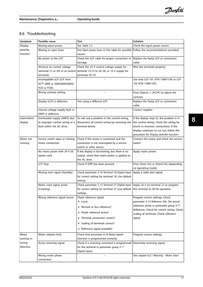
8.6 Troubleshooting
Symptom Possible cause Test Solution
Displaydark/Nofunction
Missing input power. See Table 5.5. Check the input power source.
Missing or open fuses. See Open power fuses in this table for possiblecauses.
Follow the recommendations provided.
No power to the LCP. Check the LCP cable for proper connection ordamage.
Replace the faulty LCP or connectioncable.
Shortcut on control voltage(terminal 12 or 50) or at controlterminals.
Check the 24 V control voltage supply forterminal 12/13 to 20–39, or 10 V supply forterminals 50–55.
Wire the terminals properly.
Incompatible LCP (LCP from
VLT® 2800 or 5000/6000/8000/FCD or FCM).
– Use only LCP 101 (P/N 130B1124) or LCP102 (P/N 130B1107).
Wrong contrast setting. – Press [Status] + []/[] to adjust the
contrast.
Display (LCP) is defective. Test using a different LCP. Replace the faulty LCP or connectioncable.
Internal voltage supply fault orSMPS is defective.
– Contact supplier.
Intermittentdisplay
Overloaded supply (SMPS) dueto improper control wiring or afault within the AC drive.
To rule out a problem in the control wiring,disconnect all control wiring by removing theterminal blocks.
If the display stays lit, the problem is inthe control wiring. Check the wiring forshorts or incorrect connections. If thedisplay continues to cut out, follow theprocedure for Display dark/No function.
Motor notrunning
Service switch open or missingmotor connection.
Check if the motor is connected and theconnection is not interrupted by a serviceswitch or other device.
Connect the motor and check the serviceswitch.
No mains power with 24 V DCoption card.
If the display is functioning, but there is nooutput, check that mains power is applied tothe AC drive.
Apply mains power.
LCP Stop. Check if [Off] has been pressed. Press [Auto On] or [Hand On] (dependingon operating mode).
Missing start signal (Standby). Check parameter 5-10 Terminal 18 Digital Inputfor correct setting for terminal 18. Use defaultsetting.
Apply a valid start signal.
Motor coast signal active(Coasting).
Check parameter 5-12 Terminal 27 Digital Inputfor correct setting for terminal 27 (use defaultsetting).
Apply 24 V on terminal 27 or programthis terminal to [0] No operation.
Wrong reference signal source. Check reference signal:
• Local.
• Remote or bus reference?
• Preset reference active?
• Terminal connection correct?
• Scaling of terminals correct?
• Reference signal available?
Program correct settings. Checkparameter 3-13 Reference Site. Set presetreference active in parameter group 3-1*References. Check for correct wiring. Checkscaling of terminals. Check referencesignal.
Motorrunning inwrongdirection
Motor rotation limit. Check that parameter 4-10 Motor SpeedDirection is programmed correctly.
Program correct settings.
Active reversing signal. Check if a reversing command is programmedfor the terminal in parameter group 5-1*Digital inputs.
Deactivate reversing signal.
Wrong motor phaseconnection.
– See chapter 6.5.1 Warning - Motor Start.
Maintenance, Diagnostics, a... Operating Guide
MG22A202 Danfoss A/S © 04/2018 All rights reserved. 71
8 8

Symptom Possible cause Test Solution
Motor is notreachingmaximumspeed
Frequency limits set wrong. Check output limits in parameter 4-13 MotorSpeed High Limit [RPM], parameter 4-14 MotorSpeed High Limit [Hz], and parameter 4-19 MaxOutput Frequency
Program correct limits.
Reference input signal notscaled correctly.
Check reference input signal scaling inparameter group 6-0* Analog I/O mode andparameter group 3-1* References.
Program correct settings.
Motor speedunstable
Possible incorrect parametersettings.
Check the settings of all motor parameters,including all motor compensation settings.For closed-loop operation, check PID settings.
Check settings in parameter group 1-6*Load Depen. Setting. For closed-loopoperation, check settings in parametergroup 20-0* Feedback.
Motor runsrough
Possible overmagnetization. Check for incorrect motor settings in allmotor parameters.
Check motor settings in parameter groups1-2* Motor data, 1-3* Adv Motor Data, and1-5* Load Indep. Setting.
Motor doesnot brake
Possible incorrect settings inthe brake parameters. Ramp-down times may be too short.
Check brake parameters. Check ramp timesettings.
Check parameter groups 2-0* DC Brake and3-0* Reference Limits.
Open powerfuses
Phase-to-phase short. Motor or panel has a short phase-to-phase.Check motor and panel phases for shorts.
Eliminate any shorts detected.
Motor overload. Motor is overloaded for the application. Perform start-up test and verify thatmotor current is within specifications. Ifmotor current is exceeding the nameplatefull load current, the motor can run onlywith reduced load. Review the specifi-cations for the application.
Loose connections. Perform pre-start-up check for looseconnections.
Tighten loose connections.
Mains currentimbalancegreater than3%
Problem with mains power (seealarm 4, Mains phase lossdescription).
Rotate input power leads into the 1 position:A to B, B to C, C to A.
If imbalanced leg follows the wire, it is apower problem. Check the mains supply.
Problem with the AC drive. Rotate input power leads into the AC drive 1position: A to B, B to C, C to A.
If the imbalanced leg stays on same inputterminal, it is a problem with the ACdrive. Contact supplier.
Motor currentimbalancegreater than3%
Problem with motor or motorwiring.
Rotate output motor cables 1 position: U to V,V to W, W to U.
If the imbalanced leg follows the wire, theproblem is in the motor or motor wiring.Check motor and motor wiring.
Problem with AC drive. Rotate output motor cables 1 position: U to V,V to W, W to U.
If the imbalanced leg stays on sameoutput terminal, it is a problem with theunit. Contact supplier.
AC driveaccelerationproblems
Motor data are enteredincorrectly.
If warnings or alarms occur, see chapter 8.5 List of Warnings and Alarms.Check that motor data are entered correctly.
Increase the ramp-up time inparameter 3-41 Ramp 1 Ramp Up Time.Increase current limit inparameter 4-18 Current Limit. Increasetorque limit in parameter 4-16 Torque LimitMotor Mode.
AC drivedecelerationproblems
Motor data are enteredincorrectly.
If warnings or alarms occur, see chapter 8.5 List of Warnings and Alarms.Check that motor data are entered correctly.
Increase the ramp-down time inparameter 3-42 Ramp 1 Ramp Down Time.Enable overvoltage control inparameter 2-17 Over-voltage Control.
Table 8.5 Troubleshooting
Maintenance, Diagnostics, a... VLT® AQUA Drive FC 202
72 Danfoss A/S © 04/2018 All rights reserved. MG22A202
88

9 Specifications
9.1 Electrical Data
9.1.1 Mains Supply 3x380–480 V AC
FC 202 N355 N400 N450
High/normal load HO NO HO NO HO NO(High overload=150% current during 60 s,normal overload=110% current during 60 s)
Typical shaft output at 400 V [kW] 315 355 355 400 400 450
Typical shaft output at 460 V [hp] 450 500 500 600 550 600
Typical shaft output at 480 V [kW] 355 400 400 500 500 530
Enclosure size E1h/E3h E1h/E3h E1h/E3h
Output current (3-phase)
Continuous (at 400 V) [A] 600 658 658 745 695 800
Intermittent (60 s overload)(at 400 V) [A]
900 724 987 820 1043 880
Continuous (at 460/480 V) [A] 540 590 590 678 678 730
Intermittent (60 s overload)(at 460/480 V) [A]
810 649 885 746 1017 803
Continuous kVA (at 400 V) [kVA] 416 456 456 516 482 554
Continuous kVA (at 460 V) [kVA] 430 470 470 540 540 582
Maximum input current
Continuous (at 400 V) [A] 578 634 634 718 670 771
Continuous (at 460/480 V) [A] 520 569 569 653 653 704
Maximum number and size of cablesper phase (E1h)
- Mains and motor without brake [mm2 (AWG)]1) 5x240 (5x500 mcm) 5x240 (5x500 mcm) 5x240 (5x500 mcm)
- Mains and motor with brake [mm2 (AWG)1) 4x240 (4x500 mcm) 4x240 (4x500 mcm) 4x240 (4x500 mcm)
- Brake or regeneration [mm2 (AWG)1) 2x185 (2x350 mcm) 2x185 (2x350 mcm) 2x185 (2x350 mcm)
Maximum number and size of cablesper phase (E3h)
- Mains and motor without brake [mm2 (AWG)]1) 6x240 (6x500 mcm) 6x240 (6x500 mcm) 6x240 (6x500 mcm)
- Mains and motor with brake [mm2 (AWG)1) 2x185 (2x350 mcm) 2x185 (2x350 mcm) 2x185 (2x350 mcm)
- Load share or regeneration [mm2 (AWG)1) 4x185 (4x350 mcm) 4x185 (4x350 mcm) 4x185 (4x350 mcm)
Maximum external mains fuses [A]2) 800 800 800
Estimated power loss at 400 V [W]3), 4) 6178 6928 6851 8036 7297 8783
Estimated power loss at 460 V [W] 3), 4) 5322 5910 5846 6933 7240 7969
Efficiency4) 0.98 0.98 0.98
Output frequency 0–590 Hz 0–590 Hz 0–590 Hz
Heat sink overtemperature trip [°C (°F)] 110 (230) 110 (230) 110 (230)
Control card overtemperature trip [°C (°F)] 80 (176) 80 (176) 80 (176)
Power card overtemperature trip [°C (°F)] 85 (185) 85 (185) 85 (185)
Fan power card overtemperature trip [°C (°F)] 85 (185) 85 (185) 85 (185)
Active in-rush card overtemperature trip
[°C (°F)]85 (185) 85 (185) 85 (185)
Table 9.1 Technical Specifications, Mains Supply 3x380–480 V AC
Specifications Operating Guide
MG22A202 Danfoss A/S © 04/2018 All rights reserved. 73
9 9

FC 202 N500 N560
High/normal load HO NO HO NO(High overload=150% current during 60 s, normal overload=110%current during 60 s)
Typical shaft output at 400 V [kW] 450 500 500 560
Typical shaft output at 460 V [hp] 600 650 650 750
Typical shaft output at 480 V [kW] 530 560 560 630
Enclosure size E2h/E4h E2h/E4h
Output current (3-phase)
Continuous (at 400 V) [A] 800 880 880 990
Intermittent (60 s overload)(at 400 V) [A]
1200 968 1320 1089
Continuous (at 460/480 V) [A] 730 780 780 890
Intermittent (60 s overload)(at 460/480 V) [A]
1095 858 1170 979
Continuous kVA (at 400 V) [kVA] 554 610 610 686
Continuous kVA (at 460 V) [kVA] 582 621 621 709
Maximum input current
Continuous (at 400 V) [A] 771 848 848 954
Continuous (at 460/480 V) [A] 704 752 752 858
Maximum number and size of cablesper phase (E2h)
- Mains and motor without brake [mm2 (AWG)]1) 6x240 (6x500 mcm) 6x240 (6x500 mcm)
- Mains and motor with brake [mm2 (AWG)1) 5x240 (5x500 mcm) 5x240 (5x500 mcm)
- Brake or regeneration [mm2 (AWG)1) 2x185 (2x350 mcm) 2x185 (2x350 mcm)
Maximum number and size of cablesper phase (E4h)
- Mains and motor without brake [mm2 (AWG)]1) 6x240 (6x500 mcm) 6x240 (6x500 mcm)
- Mains and motor with brake [mm2 (AWG)1) 2x185 (2x350 mcm) 2x185 (2x350 mcm)
- Load share or regeneration [mm2 (AWG)1) 4x185 (4x350 mcm) 4x185 (4x350 mcm)
Maximum external mains fuses [A]2) 1200 1200
Estimated power loss at 400 V [W]3), 4) 8352 9473 9449 11102
Estimated power loss at 460 V [W] 3), 4) 7182 7809 7771 9236
Efficiency4) 0.98 0.98
Output frequency [Hz] 0–590 0–590
Heat sink overtemperature trip [°C (°F)] 110 (230) 100 (212)
Control card overtemperature trip [°C (°F)] 80 (176) 80 (176)
Power card overtemperature trip [°C (°F)] 85 (185) 85 (185)
Fan power card overtemperature trip [°C (°F)] 85 (185) 85 (185)
Active in-rush card overtemperature trip [°C (°F)] 85 (185) 85 (185)
Table 9.2 Technical Specifications, Mains Supply 3x380–480 V AC
1) American Wire Gauge.2) For fuse ratings, see chapter 9.7 Fuses.
3) Typical power loss is at normal conditions and expected to be within ±15% (tolerance relates to variety in voltage and cable conditions.) Thesevalues are based on a typical motor efficiency (IE/IE3 border line). Lower efficiency motors add to the power loss in the drive. Applies fordimensioning of drive cooling. If the switching frequency is higher than the default setting, the power losses can increase. LCP and typical controlcard power consumptions are included. For power loss data according to EN 50598-2, refer to drives.danfoss.com/knowledge-center/energy-efficiency-directive/#/. Options and customer load can add up to 30 W to the losses, though usually a fully loaded control card and options forslots A and B each add only 4 W.4) Measured using 5 m (16.4 ft) shielded motor cables at rated load and rated frequency. Efficiency measured at nominal current. For energyefficiency class, see chapter 9.4 Ambient Conditions. For part load losses, see drives.danfoss.com/knowledge-center/energy-efficiency-directive/#/.
Specifications VLT® AQUA Drive FC 202
74 Danfoss A/S © 04/2018 All rights reserved. MG22A202
99

9.1.2 Mains Supply 3x525–690 V AC
FC 202 N450 N500
High/normal load HO NO HO NO(High overload=150% current during 60 s, normaloverload=110% current during 60 s)
Typical shaft output at 550 V [kW] 315 355 315 400
Typical shaft output at 575 V [hp] 400 450 400 500
Typical shaft output at 690 V [kW] 355 450 400 500
Enclosure size E1h/E3h E1h/E3h
Output current (3-phase)
Continuous (at 550 V) [A] 395 470 429 523
Intermittent (60 s overload) (at 550 V) [A] 593 517 644 575
Continuous (at 575/690 V) [A] 380 450 410 500
Intermittent (60 s overload) (at 575/690 V) [A] 570 495 615 550
Continuous kVA (at 550 V) [kVA] 376 448 409 498
Continuous kVA (at 575 V) [kVA] 378 448 408 498
Continuous kVA (at 690 V) [kVA] 454 538 490 598
Maximum input current
Continuous (at 550 V) [A] 381 453 413 504
Continuous (at 575/690 V) [A] 366 434 395 482
Maximum number and size of cablesper phase (E1h)
- Mains and motor without brake [mm2 (AWG)]1) 5x240 (5x500 mcm) 5x240 (5x500 mcm)
- Mains and motor with brake [mm2 (AWG)1) 4x240 (4x500 mcm) 4x240 (4x500 mcm)
- Brake or regeneration [mm2 (AWG)1) 2x185 (2x350 mcm) 2x185 (2x350 mcm)
Maximum number and size of cablesper phase (E3h)
- Mains and motor without brake [mm2 (AWG)]1) 6x240 (6x500 mcm) 6x240 (6x500 mcm)
- Mains and motor with brake [mm2 (AWG)1) 2x185 (2x350 mcm) 2x185 (2x350 mcm)
- Load share or regeneration [mm2 (AWG)1) 4x185 (4x350 mcm) 4x185 (4x350 mcm)
Maximum external mains fuses [A]2) 800 800
Estimated power loss at 600 V [W]3), 4) 4989 6062 5419 6879
Estimated power loss at 690 V [W]3), 4) 4920 5939 5332 6715
Efficiency4) 0.98 0.98
Output frequency [Hz] 0–500 0–500
Heat sink overtemperature trip [°C (°F)] 110 (230) 110 (230)
Control card overtemperature trip [°C (°F)] 80 (176) 80 (176)
Power card overtemperature trip [°C (°F)] 85 (185) 85 (185)
Fan power card overtemperature trip [°C (°F)] 85 (185) 85 (185)
Active in-rush card overtemperature trip [°C (°F)] 85 (185) 85 (185)
Table 9.3 Technical Specifications, Mains Supply 3x525–690 V AC
Specifications Operating Guide
MG22A202 Danfoss A/S © 04/2018 All rights reserved. 75
9 9
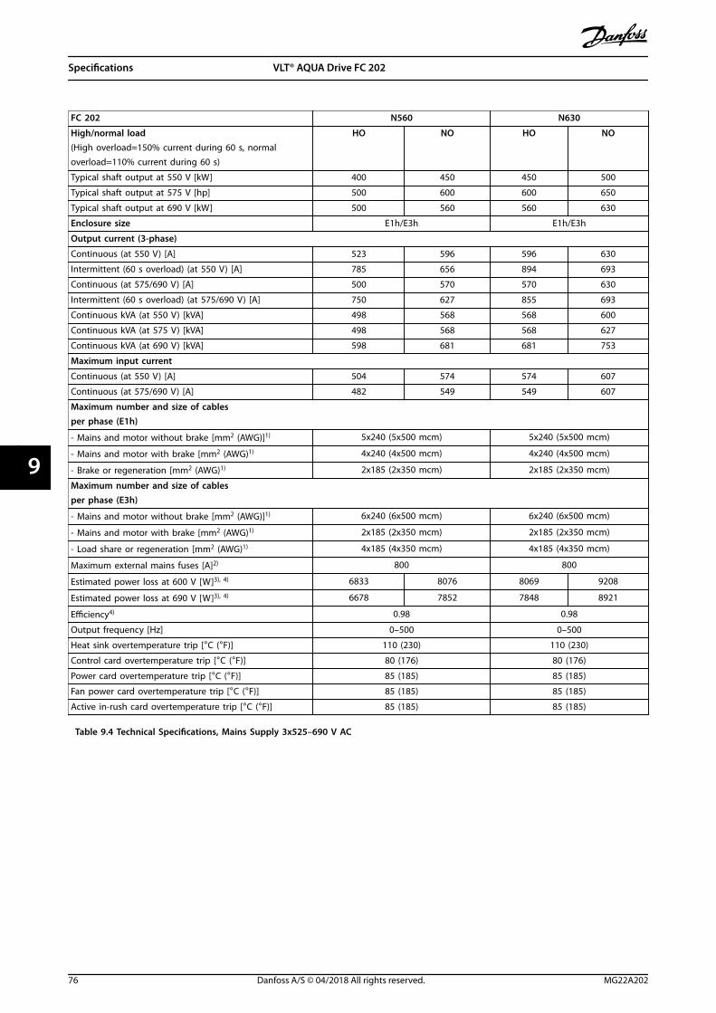
FC 202 N560 N630
High/normal load HO NO HO NO(High overload=150% current during 60 s, normaloverload=110% current during 60 s)
Typical shaft output at 550 V [kW] 400 450 450 500
Typical shaft output at 575 V [hp] 500 600 600 650
Typical shaft output at 690 V [kW] 500 560 560 630
Enclosure size E1h/E3h E1h/E3h
Output current (3-phase)
Continuous (at 550 V) [A] 523 596 596 630
Intermittent (60 s overload) (at 550 V) [A] 785 656 894 693
Continuous (at 575/690 V) [A] 500 570 570 630
Intermittent (60 s overload) (at 575/690 V) [A] 750 627 855 693
Continuous kVA (at 550 V) [kVA] 498 568 568 600
Continuous kVA (at 575 V) [kVA] 498 568 568 627
Continuous kVA (at 690 V) [kVA] 598 681 681 753
Maximum input current
Continuous (at 550 V) [A] 504 574 574 607
Continuous (at 575/690 V) [A] 482 549 549 607
Maximum number and size of cablesper phase (E1h)
- Mains and motor without brake [mm2 (AWG)]1) 5x240 (5x500 mcm) 5x240 (5x500 mcm)
- Mains and motor with brake [mm2 (AWG)1) 4x240 (4x500 mcm) 4x240 (4x500 mcm)
- Brake or regeneration [mm2 (AWG)1) 2x185 (2x350 mcm) 2x185 (2x350 mcm)
Maximum number and size of cablesper phase (E3h)
- Mains and motor without brake [mm2 (AWG)]1) 6x240 (6x500 mcm) 6x240 (6x500 mcm)
- Mains and motor with brake [mm2 (AWG)1) 2x185 (2x350 mcm) 2x185 (2x350 mcm)
- Load share or regeneration [mm2 (AWG)1) 4x185 (4x350 mcm) 4x185 (4x350 mcm)
Maximum external mains fuses [A]2) 800 800
Estimated power loss at 600 V [W]3), 4) 6833 8076 8069 9208
Estimated power loss at 690 V [W]3), 4) 6678 7852 7848 8921
Efficiency4) 0.98 0.98
Output frequency [Hz] 0–500 0–500
Heat sink overtemperature trip [°C (°F)] 110 (230) 110 (230)
Control card overtemperature trip [°C (°F)] 80 (176) 80 (176)
Power card overtemperature trip [°C (°F)] 85 (185) 85 (185)
Fan power card overtemperature trip [°C (°F)] 85 (185) 85 (185)
Active in-rush card overtemperature trip [°C (°F)] 85 (185) 85 (185)
Table 9.4 Technical Specifications, Mains Supply 3x525–690 V AC
Specifications VLT® AQUA Drive FC 202
76 Danfoss A/S © 04/2018 All rights reserved. MG22A202
99
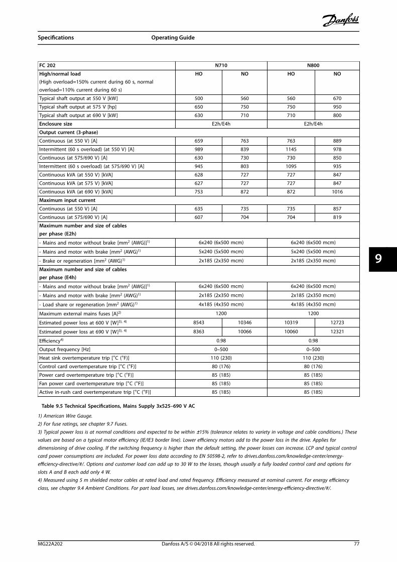
FC 202 N710 N800
High/normal load HO NO HO NO(High overload=150% current during 60 s, normaloverload=110% current during 60 s)
Typical shaft output at 550 V [kW] 500 560 560 670
Typical shaft output at 575 V [hp] 650 750 750 950
Typical shaft output at 690 V [kW] 630 710 710 800
Enclosure size E2h/E4h E2h/E4h
Output current (3-phase)
Continuous (at 550 V) [A] 659 763 763 889
Intermittent (60 s overload) (at 550 V) [A] 989 839 1145 978
Continuous (at 575/690 V) [A] 630 730 730 850
Intermittent (60 s overload) (at 575/690 V) [A] 945 803 1095 935
Continuous kVA (at 550 V) [kVA] 628 727 727 847
Continuous kVA (at 575 V) [kVA] 627 727 727 847
Continuous kVA (at 690 V) [kVA] 753 872 872 1016
Maximum input current
Continuous (at 550 V) [A] 635 735 735 857
Continuous (at 575/690 V) [A] 607 704 704 819
Maximum number and size of cablesper phase (E2h)
- Mains and motor without brake [mm2 (AWG)]1) 6x240 (6x500 mcm) 6x240 (6x500 mcm)
- Mains and motor with brake [mm2 (AWG)1) 5x240 (5x500 mcm) 5x240 (5x500 mcm)
- Brake or regeneration [mm2 (AWG)1) 2x185 (2x350 mcm) 2x185 (2x350 mcm)
Maximum number and size of cablesper phase (E4h)
- Mains and motor without brake [mm2 (AWG)]1) 6x240 (6x500 mcm) 6x240 (6x500 mcm)
- Mains and motor with brake [mm2 (AWG)1) 2x185 (2x350 mcm) 2x185 (2x350 mcm)
- Load share or regeneration [mm2 (AWG)1) 4x185 (4x350 mcm) 4x185 (4x350 mcm)
Maximum external mains fuses [A]2) 1200 1200
Estimated power loss at 600 V [W]3), 4) 8543 10346 10319 12723
Estimated power loss at 690 V [W]3), 4) 8363 10066 10060 12321
Efficiency4) 0.98 0.98
Output frequency [Hz] 0–500 0–500
Heat sink overtemperature trip [°C (°F)] 110 (230) 110 (230)
Control card overtemperature trip [°C (°F)] 80 (176) 80 (176)
Power card overtemperature trip [°C (°F)] 85 (185) 85 (185)
Fan power card overtemperature trip [°C (°F)] 85 (185) 85 (185)
Active in-rush card overtemperature trip [°C (°F)] 85 (185) 85 (185)
Table 9.5 Technical Specifications, Mains Supply 3x525–690 V AC
1) American Wire Gauge.2) For fuse ratings, see chapter 9.7 Fuses.
3) Typical power loss is at normal conditions and expected to be within ±15% (tolerance relates to variety in voltage and cable conditions.) Thesevalues are based on a typical motor efficiency (IE/IE3 border line). Lower efficiency motors add to the power loss in the drive. Applies fordimensioning of drive cooling. If the switching frequency is higher than the default setting, the power losses can increase. LCP and typical controlcard power consumptions are included. For power loss data according to EN 50598-2, refer to drives.danfoss.com/knowledge-center/energy-efficiency-directive/#/. Options and customer load can add up to 30 W to the losses, though usually a fully loaded control card and options forslots A and B each add only 4 W.4) Measured using 5 m shielded motor cables at rated load and rated frequency. Efficiency measured at nominal current. For energy efficiencyclass, see chapter 9.4 Ambient Conditions. For part load losses, see drives.danfoss.com/knowledge-center/energy-efficiency-directive/#/.
Specifications Operating Guide
MG22A202 Danfoss A/S © 04/2018 All rights reserved. 77
9 9
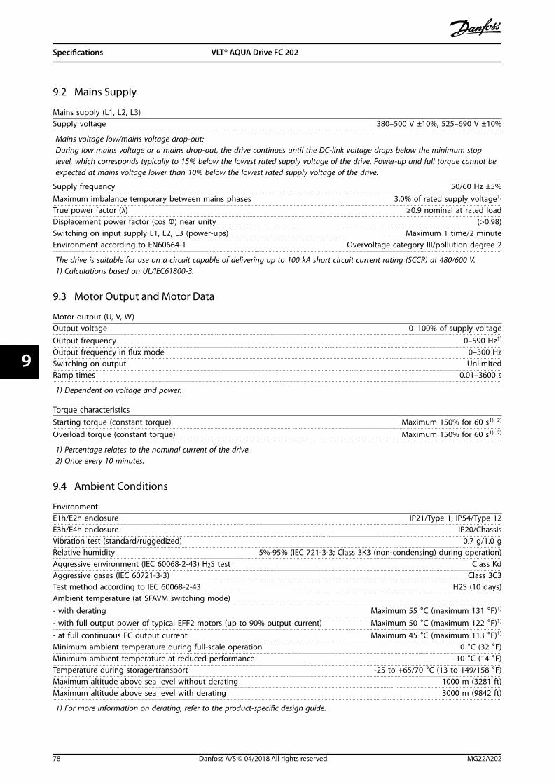
9.2 Mains Supply
Mains supply (L1, L2, L3)Supply voltage 380–500 V ±10%, 525–690 V ±10%
Mains voltage low/mains voltage drop-out:During low mains voltage or a mains drop-out, the drive continues until the DC-link voltage drops below the minimum stoplevel, which corresponds typically to 15% below the lowest rated supply voltage of the drive. Power-up and full torque cannot beexpected at mains voltage lower than 10% below the lowest rated supply voltage of the drive.
Supply frequency 50/60 Hz ±5%Maximum imbalance temporary between mains phases 3.0% of rated supply voltage1)
True power factor (λ) ≥0.9 nominal at rated loadDisplacement power factor (cos Φ) near unity (>0.98)Switching on input supply L1, L2, L3 (power-ups) Maximum 1 time/2 minuteEnvironment according to EN60664-1 Overvoltage category III/pollution degree 2
The drive is suitable for use on a circuit capable of delivering up to 100 kA short circuit current rating (SCCR) at 480/600 V.1) Calculations based on UL/IEC61800-3.
9.3 Motor Output and Motor Data
Motor output (U, V, W)Output voltage 0–100% of supply voltageOutput frequency 0–590 Hz1)
Output frequency in flux mode 0–300 HzSwitching on output UnlimitedRamp times 0.01–3600 s
1) Dependent on voltage and power.
Torque characteristicsStarting torque (constant torque) Maximum 150% for 60 s1), 2)
Overload torque (constant torque) Maximum 150% for 60 s1), 2)
1) Percentage relates to the nominal current of the drive.2) Once every 10 minutes.
9.4 Ambient Conditions
EnvironmentE1h/E2h enclosure IP21/Type 1, IP54/Type 12E3h/E4h enclosure IP20/ChassisVibration test (standard/ruggedized) 0.7 g/1.0 gRelative humidity 5%-95% (IEC 721-3-3; Class 3K3 (non-condensing) during operation)Aggressive environment (IEC 60068-2-43) H2S test Class KdAggressive gases (IEC 60721-3-3) Class 3C3Test method according to IEC 60068-2-43 H2S (10 days)Ambient temperature (at SFAVM switching mode)- with derating Maximum 55 °C (maximum 131 °F)1)
- with full output power of typical EFF2 motors (up to 90% output current) Maximum 50 °C (maximum 122 °F)1)
- at full continuous FC output current Maximum 45 °C (maximum 113 °F)1)
Minimum ambient temperature during full-scale operation 0 °C (32 °F)Minimum ambient temperature at reduced performance -10 °C (14 °F)Temperature during storage/transport -25 to +65/70 °C (13 to 149/158 °F)Maximum altitude above sea level without derating 1000 m (3281 ft)Maximum altitude above sea level with derating 3000 m (9842 ft)
1) For more information on derating, refer to the product-specific design guide.
Specifications VLT® AQUA Drive FC 202
78 Danfoss A/S © 04/2018 All rights reserved. MG22A202
99

EMC standards, Emission EN 61800-3EMC standards, Immunity EN 61800-3Energy efficiency class2) IE2
2) Determined according to EN 50598-2 at:
• Rated load.
• 90% rated frequency.
• Switching frequency factory setting.
• Switching pattern factory setting.
9.5 Cable Specifications
Cable lengths and cross-sections for control cables1)
Maximum motor cable length, shielded/armored 150 m (492 ft)Maximum motor cable length, unshielded/unarmored 300 m (984 ft)Maximum cross-section to motor, mains, load sharing, and brake See chapter 9.1 Electrical DataMaximum cross-section to control terminals, rigid wire 1.5 mm2/16 AWG (2x0.75 mm2)Maximum cross-section to control terminals, flexible cable 1 mm2/18 AWGMaximum cross-section to control terminals, cable with enclosed core 0.5 mm2/20 AWGMinimum cross-section to control terminals. 0.25 mm2/23 AWG
1) For power cables, see electrical tables in chapter 9.1 Electrical Data.
9.6 Control Input/Output and Control Data
Digital inputsProgrammable digital inputs 4 (6)Terminal number 18, 19, 271), 291), 32, 33Logic PNP or NPNVoltage level 0–24 V DCVoltage level, logic 0 PNP <5 V DCVoltage level, logic 1 PNP >10 V DCVoltage level, logic 0 NPN >19 V DCVoltage level, logic 1 NPN <14 V DCMaximum voltage on input 28 V DCInput resistance, Ri Approximately 4 kΩ
All digital inputs are galvanically isolated from the supply voltage (PELV) and other high-voltage terminals.1) Terminals 27 and 29 can also be programmed as outputs.
Analog inputsNumber of analog inputs 2Terminal number 53, 54Modes Voltage or currentMode select Switches A53 and A54Voltage mode Switch A53/A54=(U)Voltage level -10 V to +10 V (scaleable)Input resistance, Ri Approximately 10 kΩMaximum voltage ±20 VCurrent mode Switch A53/A54=(I)Current level 0/4 to 20 mA (scaleable)Input resistance, Ri Approximately 200 ΩMaximum current 30 mAResolution for analog inputs 10 bit (+ sign)Accuracy of analog inputs Maximum error 0.5% of full scaleBandwidth 100 Hz
The analog inputs are galvanically isolated from the supply voltage (PELV) and other high-voltage terminals.
Specifications Operating Guide
MG22A202 Danfoss A/S © 04/2018 All rights reserved. 79
9 9

Mains
Functionalisolation
PELV isolation
Motor
DC-bus
Highvoltage
Control+24 V
RS485
18
37
130B
A11
7.10
Illustration 9.1 PELV Isolation
Pulse inputsProgrammable pulse inputs 2Terminal number pulse 29, 33Maximum frequency at terminal 29, 33 110 kHz (push-pull driven)Maximum frequency at terminal 29, 33 5 kHz (open collector)Minimum frequency at terminal 29, 33 4 HzVoltage level See Digital Inputs in chapter 9.6 Control Input/Output and Control Data Maximum voltage on input 28 V DCInput resistance, Ri Approximately 4 kΩPulse input accuracy (0.1–1 kHz) Maximum error: 0.1% of full scale
Analog outputNumber of programmable analog outputs 1Terminal number 42Current range at analog output 0/4-20 mAMaximum resistor load to common at analog output 500 ΩAccuracy on analog output Maximum error: 0.8% of full scaleResolution on analog output 8 bit
The analog output is galvanically isolated from the supply voltage (PELV) and other high-voltage terminals.
Control card, RS485 serial communicationTerminal number 68 (P, TX+, RX+), 69 (N, TX-, RX-)Terminal number 61 Common for terminals 68 and 69
The RS485 serial communication circuit is functionally separated from other central circuits and galvanically isolated from thesupply voltage (PELV).
Digital outputProgrammable digital/pulse outputs 2Terminal number 27, 291)
Voltage level at digital/frequency output 0–24 VMaximum output current (sink or source) 40 mAMaximum load at frequency output 1 kΩMaximum capacitive load at frequency output 10 nFMinimum output frequency at frequency output 0 HzMaximum output frequency at frequency output 32 kHzAccuracy of frequency output Maximum error: 0.1% of full scaleResolution of frequency outputs 12 bit
1) Terminals 27 and 29 can also be programmed as inputs.
The digital output is galvanically isolated from the supply voltage (PELV) and other high-voltage terminals.
Specifications VLT® AQUA Drive FC 202
80 Danfoss A/S © 04/2018 All rights reserved. MG22A202
99

Control card, 24 V DC outputTerminal number 12, 13Maximum load 200 mA
The 24 V DC supply is galvanically isolated from the supply voltage (PELV), but has the same potential as the analog and digitalinputs and outputs.
Relay outputsProgrammable relay outputs 2Maximum cross-section to relay terminals 2.5 mm2 (12 AWG)Minimum cross-section to relay terminals 0.2 mm2 (30 AWG)Length of stripped wire 8 mm (0.3 in)Relay 01 terminal number 1–3 (break), 1–2 (make)Maximum terminal load (AC-1)1) on 1–2 (NO) (Resistive load)2), 3) 400 V AC, 2 AMaximum terminal load (AC-15)1) on 1–2 (NO) (Inductive load @ cosφ 0.4) 240 V AC, 0.2 AMaximum terminal load (DC-1)1) on 1–2 (NO) (Resistive load) 80 V DC, 2 AMaximum terminal load (DC-13)1) on 1–2 (NO) (Inductive load) 24 V DC, 0.1 AMaximum terminal load (AC-1)1) on 1–3 (NC) (Resistive load) 240 V AC, 2 AMaximum terminal load (AC-15)1) on 1–3 (NC) (Inductive load @ cosφ 0.4) 240 V AC, 0.2 AMaximum terminal load (DC-1)1) on 1–3 (NC) (Resistive load) 50 V DC, 2 AMaximum terminal load (DC-13)1) on 1–3 (NC) (Inductive load) 24 V DC, 0.1 AMinimum terminal load on 1–3 (NC), 1–2 (NO) 24 V DC 10 mA, 24 V AC 2 mAEnvironment according to EN 60664-1 Overvoltage category III/pollution degree 2Relay 02 terminal number 4–6 (break), 4–5 (make)Maximum terminal load (AC-1)1) on 4–5 (NO) (Resistive load)2), 3) 400 V AC, 2 AMaximum terminal load (AC-15)1) on 4–5 (NO) (Inductive load @ cosφ 0.4) 240 V AC, 0.2 AMaximum terminal load (DC-1)1) on 4–5 (NO) (Resistive load) 80 V DC, 2 AMaximum terminal load (DC-13)1) on 4–5 (NO) (Inductive load) 24 V DC, 0.1 AMaximum terminal load (AC-1)1) on 4–6 (NC) (Resistive load) 240 V AC, 2 AMaximum terminal load (AC-15)1) on 4–6 (NC) (Inductive load @ cosφ 0.4) 240 V AC, 0.2 AMaximum terminal load (DC-1)1) on 4–6 (NC) (Resistive load) 50 V DC, 2 AMaximum terminal load (DC-13)1) on 4–6 (NC) (Inductive load) 24 V DC, 0.1 AMinimum terminal load on 4–6 (NC), 4–5 (NO) 24 V DC 10 mA, 24 V AC 2 mAEnvironment according to EN 60664-1 Overvoltage category III/pollution degree 2
1) IEC 60947 part 4 and 5.The relay contacts are galvanically isolated from the rest of the circuit by reinforced isolation (PELV).2) Overvoltage Category II.3) UL applications 300 V AC 2 A.
Control card, +10 V DC outputTerminal number 50Output voltage 10.5 V ±0.5 VMaximum load 25 mA
The 10 V DC supply is galvanically isolated from the supply voltage (PELV) and other high-voltage terminals.
Control characteristicsResolution of output frequency at 0–1000 Hz ±0.003 HzSystem response time (terminals 18, 19, 27, 29, 32, 33) ≤2 m/sSpeed control range (open loop) 1:100 of synchronous speedSpeed accuracy (open loop) 30–4000 RPM: Maximum error of ±8 RPM
All control characteristics are based on a 4-pole asynchronous motor.
Control card performanceScan interval 5 M/S
Specifications Operating Guide
MG22A202 Danfoss A/S © 04/2018 All rights reserved. 81
9 9
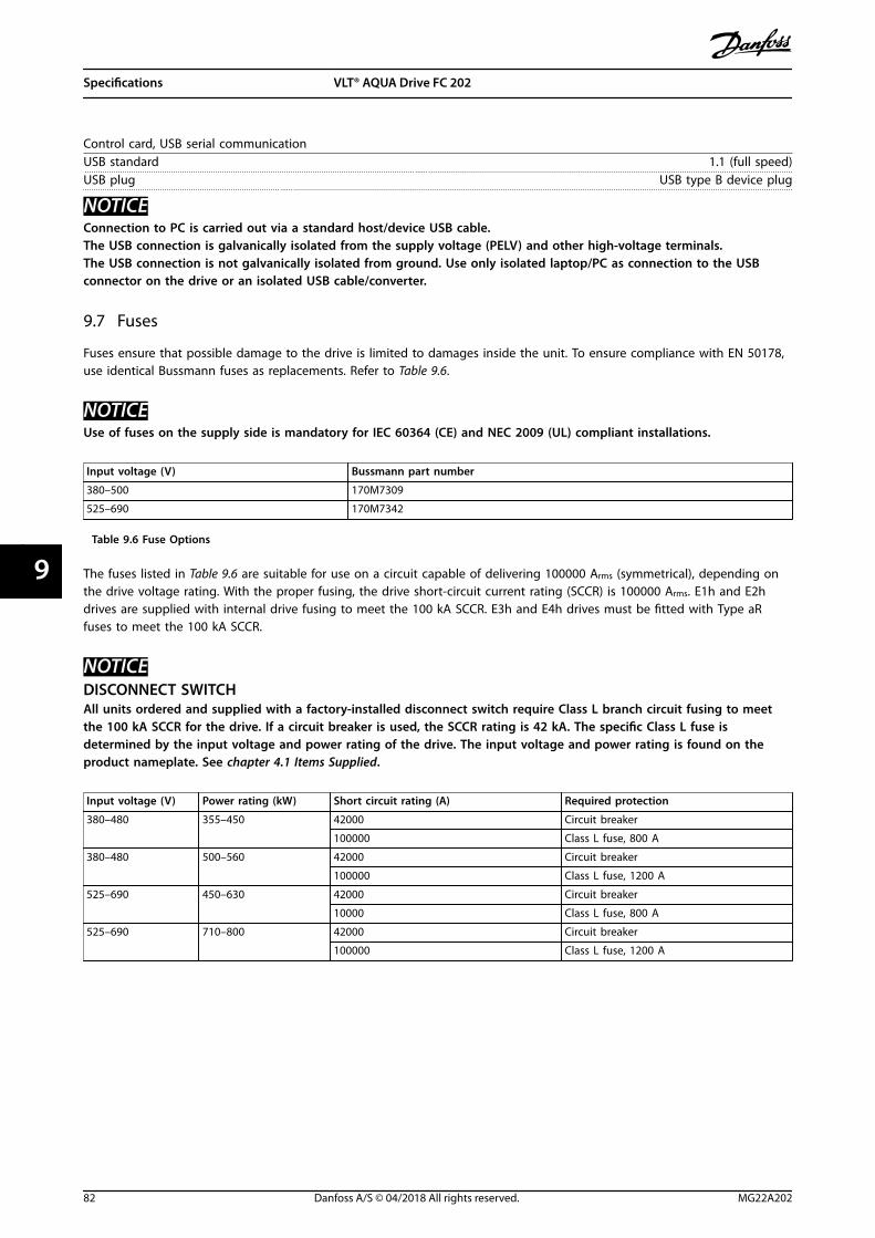
Control card, USB serial communicationUSB standard 1.1 (full speed)USB plug USB type B device plug
NOTICEConnection to PC is carried out via a standard host/device USB cable.The USB connection is galvanically isolated from the supply voltage (PELV) and other high-voltage terminals.The USB connection is not galvanically isolated from ground. Use only isolated laptop/PC as connection to the USBconnector on the drive or an isolated USB cable/converter.
9.7 Fuses
Fuses ensure that possible damage to the drive is limited to damages inside the unit. To ensure compliance with EN 50178,use identical Bussmann fuses as replacements. Refer to Table 9.6.
NOTICEUse of fuses on the supply side is mandatory for IEC 60364 (CE) and NEC 2009 (UL) compliant installations.
Input voltage (V) Bussmann part number
380–500 170M7309
525–690 170M7342
Table 9.6 Fuse Options
The fuses listed in Table 9.6 are suitable for use on a circuit capable of delivering 100000 Arms (symmetrical), depending onthe drive voltage rating. With the proper fusing, the drive short-circuit current rating (SCCR) is 100000 Arms. E1h and E2hdrives are supplied with internal drive fusing to meet the 100 kA SCCR. E3h and E4h drives must be fitted with Type aRfuses to meet the 100 kA SCCR.
NOTICEDISCONNECT SWITCHAll units ordered and supplied with a factory-installed disconnect switch require Class L branch circuit fusing to meetthe 100 kA SCCR for the drive. If a circuit breaker is used, the SCCR rating is 42 kA. The specific Class L fuse isdetermined by the input voltage and power rating of the drive. The input voltage and power rating is found on theproduct nameplate. See chapter 4.1 Items Supplied.
Input voltage (V) Power rating (kW) Short circuit rating (A) Required protection
380–480 355–450 42000 Circuit breaker
100000 Class L fuse, 800 A
380–480 500–560 42000 Circuit breaker
100000 Class L fuse, 1200 A
525–690 450–630 42000 Circuit breaker
10000 Class L fuse, 800 A
525–690 710–800 42000 Circuit breaker
100000 Class L fuse, 1200 A
Specifications VLT® AQUA Drive FC 202
82 Danfoss A/S © 04/2018 All rights reserved. MG22A202
99

9.8 Enclosure Dimensions
9.8.1 E1h Exterior Dimensions
130B
F648
.10
22 (0.8)
393 (15.5)
602 (23.7)
2043(80.4)
2002(78.8)
1553(61.1)
1393(54.9)
912(35.9)
13 (0.5)3X
Illustration 9.2 Front View of E1h
Specifications Operating Guide
MG22A202 Danfoss A/S © 04/2018 All rights reserved. 83
9 9

130B
F649
.10
20 (0.8)2X
2X 101 (4.0)
2X 9 (0.7)
2X 35 (1.4)
2X 125 (4.9)
2X280 (11.0)
2X 190 (7.5)
1
513(20.2)
567(22.3)
1 Knockout panel
Illustration 9.3 Side View of E1h
Specifications VLT® AQUA Drive FC 202
84 Danfoss A/S © 04/2018 All rights reserved. MG22A202
99

130B
F684
.10
168 (6.6)
18 (0.7)
412 (16.2)
154 (6.1)
206(8.1)
1209 (47.6)
168 (6.6)
1800 (70.9)
601 (23.7)
69 (2.7) 464 (18.3)
4X 457 (18.0)4X 73 (2.8)
1
96 (3.8)
1 Heat sink access panel (optional)
Illustration 9.4 Back View of E1h
Specifications Operating Guide
MG22A202 Danfoss A/S © 04/2018 All rights reserved. 85
9 9

130B
F651
.10
1
A
293 (11.5)
173 (6.8)
560 (22.0)22 (0.8)
17 (0.7)
14 (0.6)
A
11 (0.4)
750 (29.5)
558 (22.0)
75
22 (0.8)
137(5.4)
560 (22.0)
412 (16.2)
184(7.3)
424 (16.7)
1 Gland plate
Illustration 9.5 Door Clearance and Gland Plate Dimensions for E1h
Specifications VLT® AQUA Drive FC 202
86 Danfoss A/S © 04/2018 All rights reserved. MG22A202
99

9.8.2 E2h Exterior Dimensions
2043(80.4)
2002(78.8)
1553(61.1)
1393(54.9)
912(35.9)
394(15.5)
698(27.5)
97(3.8) 13 (0.5)3X
130B
F654
.10
Illustration 9.6 Front View of E2h
Specifications Operating Guide
MG22A202 Danfoss A/S © 04/2018 All rights reserved. 87
9 9
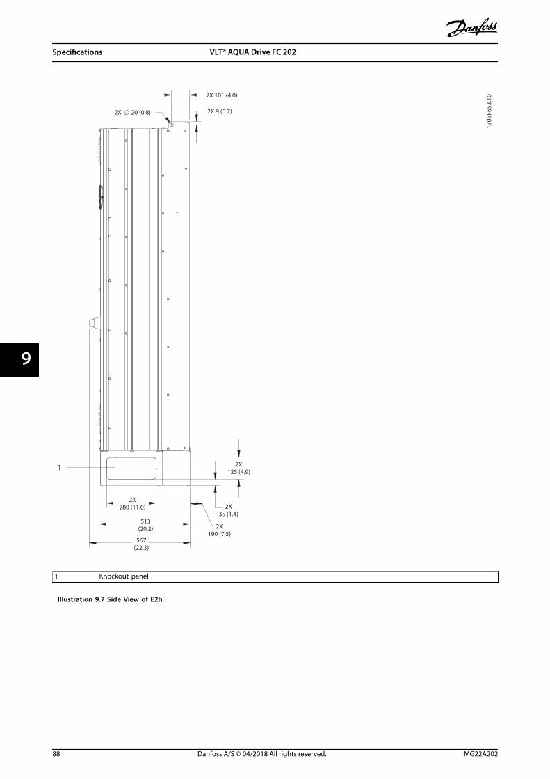
2X 101 (4.0)
2X 9 (0.7)20 (0.8)2X
1
513(20.2)
567(22.3)
2X280 (11.0)
2X 190 (7.5)
2X 35 (1.4)
2X 125 (4.9)
130B
F653
.10
1 Knockout panel
Illustration 9.7 Side View of E2h
Specifications VLT® AQUA Drive FC 202
88 Danfoss A/S © 04/2018 All rights reserved. MG22A202
99

130B
F655
.10
168 (6.6)
18 (0.7)96 (3.8)
154 (6.1)
1800 (70.9)
168 (6.6)
601 (23.7)
69 (2.7)
4X 121 (4.8)
560 (22.0)
4X 457 (18.0)
1209 (47.6)
508 (20.0)
254(10.0)
1
1 Heat sink access panel (optional)
Illustration 9.8 Back View of E2h
Specifications Operating Guide
MG22A202 Danfoss A/S © 04/2018 All rights reserved. 89
9 9

75
14 (0.6)
A
11 (0.4)
130B
F652
.10
A
871 (34.3)
424 (16.7)
184(7.3)
17 (0.7)137(5.4)
653 (25.7)
22 (0.8)
508 (20.0)
656 (25.8)
1
293 (11.5)
173 (6.8)
656 (25.8)22 (0.8)
1 Gland plate
Illustration 9.9 Door Clearance and Gland Plate Dimensions for E2h
Specifications VLT® AQUA Drive FC 202
90 Danfoss A/S © 04/2018 All rights reserved. MG22A202
99

9.8.3 E3h Exterior Dimensions
130B
F656
.10
1578(62.1)
1537(60.5)
1348(53.1)
13 (0.5)3X
506(19.9)
30(1.2)
13 (0.5)
10 (0.4)
10 (0.4)
15 (0.6)
A
A
Illustration 9.10 Front View of E3h
Specifications Operating Guide
MG22A202 Danfoss A/S © 04/2018 All rights reserved. 91
9 9

130B
F658
.10
20 (0.8)2X2X 101 (4.0)
2X 19 (0.7)
2X 18 (0.7)
2X 21 (0.8)
482 (19.0)
Illustration 9.11 Side View of E3h
Specifications VLT® AQUA Drive FC 202
92 Danfoss A/S © 04/2018 All rights reserved. MG22A202
99

130B
F657
.10
168 (6.6)
18 (0.7)
168 (6.6)
1335 (52.5)
136 (5.4)
154 (6.1)
744 (29.3)
39 (1.5)
22 (0.9)
215 (8.5)
48 (1.9) 206(8.1)
412(16.2)
430 (16.9)
4X 457 (18.0)
464 (18.3)
1
1 Heat sink access panel (optional)
Illustration 9.12 Back View of E3h
Specifications Operating Guide
MG22A202 Danfoss A/S © 04/2018 All rights reserved. 93
9 9
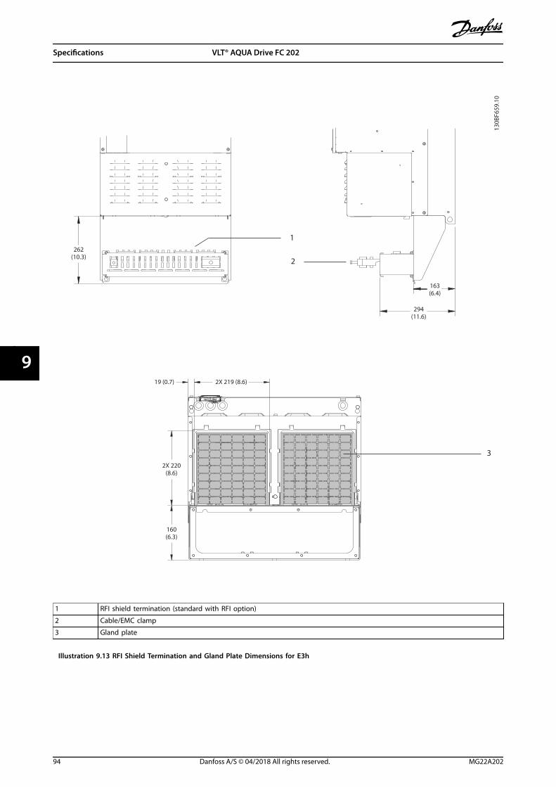
130B
F659
.10
262(10.3)
294(11.6)
1
3
163(6.4)
19 (0.7) 2X 219 (8.6)
2X 220(8.6)
160(6.3)
2
1 RFI shield termination (standard with RFI option)
2 Cable/EMC clamp
3 Gland plate
Illustration 9.13 RFI Shield Termination and Gland Plate Dimensions for E3h
Specifications VLT® AQUA Drive FC 202
94 Danfoss A/S © 04/2018 All rights reserved. MG22A202
99

9.8.4 E4h Exterior Dimensions
130B
F664
.10
13 (0.5)
10 (0.4)
10 (0.4)
15 (0.6)
A
A
1578(62.1) 1537
(60.5)
1348(53.1)
30(1.2)
604(23.8)
13 (0.5)3X
Illustration 9.14 Front View of E4h
Specifications Operating Guide
MG22A202 Danfoss A/S © 04/2018 All rights reserved. 95
9 9

130B
F666
.1020 (0.8)2X
2X 101 (4.0)
2X 19 (0.7)
2X 18 (0.7)
2X 21 (0.8)
482 (19.0)
Illustration 9.15 Side View of E4h
Specifications VLT® AQUA Drive FC 202
96 Danfoss A/S © 04/2018 All rights reserved. MG22A202
99

130B
F665
.10
18 (0.7)48 (1.9)
508(20.1)
254(10.0)
168 (6.6)
1335 (52.5)
168 (6.6)
136 (5.4)
39 (1.5)
22 (0.9)
263 (10.4)
4X 457 (18.0)
744 (29.3)
4X 74 (2.9)
560 (22.0)
526 (20.7)
154 (6.1)
1
1 Heat sink access panel (optional)
Illustration 9.16 Back View of E4h
Specifications Operating Guide
MG22A202 Danfoss A/S © 04/2018 All rights reserved. 97
9 9

294(11.6)
163(6.4)
130B
F667
.10
262(10.3)
1
3
19 (0.7) 2X 268 (10.6)
2X 220(8.6)
160(6.3)
2
1 RFI shield termination (standard with RFI option)
2 Cable/EMC clamp
3 Gland plate
Illustration 9.17 RFI Shield Termination and Gland Plate Dimensions for E4h
Specifications VLT® AQUA Drive FC 202
98 Danfoss A/S © 04/2018 All rights reserved. MG22A202
99

9.9 Enclosure Airflow
9.9.1 Airflow for E1h–E4h Enclosures
225 mm (8.9 in)
225 mm (8.9 in)
225 mm (8.9 in)
130B
F699
.10
Illustration 9.18 Standard Airflow Configuration for E1h/E2h (Left) and E3h/E4h (Right)
225 mm (8.9 in)
130B
F700
.10
Illustration 9.19 Optional Airflow Configuration Through the Back Wall for E1h/E2h (Left) and E3h/E4h (Right)
Specifications Operating Guide
MG22A202 Danfoss A/S © 04/2018 All rights reserved. 99
9 9

9.10 Fastener Torque Ratings
Apply the correct torque when tightening fasteners in the locations that are listed in Table 9.7. Too low or too high torquewhen fastening an electrical connection results in a bad electrical connection. To ensure correct torque, use a torquewrench.
Location Bolt size Torque [Nm (in-lb)]
Mains terminals M10/M12 19 (168)/37 (335)
Motor terminals M10/M12 19 (168)/37 (335)
Ground terminals M8/M10 9.6 (84)/19.1 (169)
Brake terminals M8 9.6 (84)
Load sharing terminals M10/M12 19 (168)/37 (335)
Regeneration terminals (Enclosures E1h/E2h) M8 9.6 (84)
Regeneration terminals (Enclosures E3h/E4h) M10/M12 19 (168)/37 (335)
Relay terminals _ 0.5 (4)
Door/panel cover M5 2.3 (20)
Gland plate M5 2.3 (20)
Heat sink access panel M5 3.9 (35)
Serial communication cover M5 2.3 (20)
Table 9.7 Fastener Torque Ratings
Specifications VLT® AQUA Drive FC 202
100 Danfoss A/S © 04/2018 All rights reserved. MG22A202
99
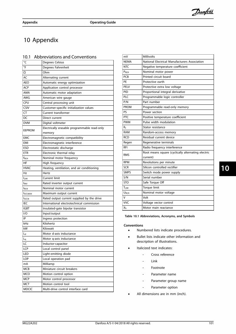
10 Appendix
10.1 Abbreviations and Conventions°C Degrees Celsius
°F Degrees Fahrenheit
Ω Ohm
AC Alternating current
AEO Automatic energy optimization
ACP Application control processor
AMA Automatic motor adaptation
AWG American wire gauge
CPU Central processing unit
CSIV Customer-specific initialization values
CT Current transformer
DC Direct current
DVM Digital voltmeter
EEPROMElectrically erasable programmable read-onlymemory
EMC Electromagnetic compatibility
EMI Electromagnetic interference
ESD Electrostatic discharge
ETR Electronic thermal relay
fM,N Nominal motor frequency
HF High frequency
HVAC Heating, ventilation, and air conditioning
Hz Hertz
ILIM Current limit
IINV Rated inverter output current
IM,N Nominal motor current
IVLT,MAX Maximum output current
IVLT,N Rated output current supplied by the drive
IEC International electrotechnical commission
IGBT Insulated-gate bipolar transistor
I/O Input/output
IP Ingress protection
kHz Kilohertz
kW Kilowatt
Ld Motor d-axis inductance
Lq Motor q-axis inductance
LC Inductor-capacitor
LCP Local control panel
LED Light-emitting diode
LOP Local operation pad
mA Milliamp
MCB Miniature circuit breakers
MCO Motion control option
MCP Motor control processor
MCT Motion control tool
MDCIC Multi-drive control interface card
mV Millivolts
NEMA National Electrical Manufacturers Association
NTC Negative temperature coefficient
PM,N Nominal motor power
PCB Printed circuit board
PE Protective earth
PELV Protective extra low voltage
PID Proportional integral derivative
PLC Programmable logic controller
P/N Part number
PROM Programmable read-only memory
PS Power section
PTC Positive temperature coefficient
PWM Pulse width modulation
Rs Stator resistance
RAM Random-access memory
RCD Residual current device
Regen Regenerative terminals
RFI Radio frequency interference
RMSRoot means square (cyclically alternating electriccurrent)
RPM Revolutions per minute
SCR Silicon controlled rectifier
SMPS Switch mode power supply
S/N Serial number
STO Safe Torque Off
TLIM Torque limit
UM,N Nominal motor voltage
V Volt
VVC Voltage vector control
Xh Motor main reactance
Table 10.1 Abbreviations, Acronyms, and Symbols
Conventions• Numbered lists indicate procedures.
• Bullet lists indicate other information anddescription of illustrations.
• Italicized text indicates:
- Cross reference
- Link
- Footnote
- Parameter name
- Parameter group name
- Parameter option
• All dimensions are in mm (inch).
Appendix Operating Guide
MG22A202 Danfoss A/S © 04/2018 All rights reserved. 101
10 10
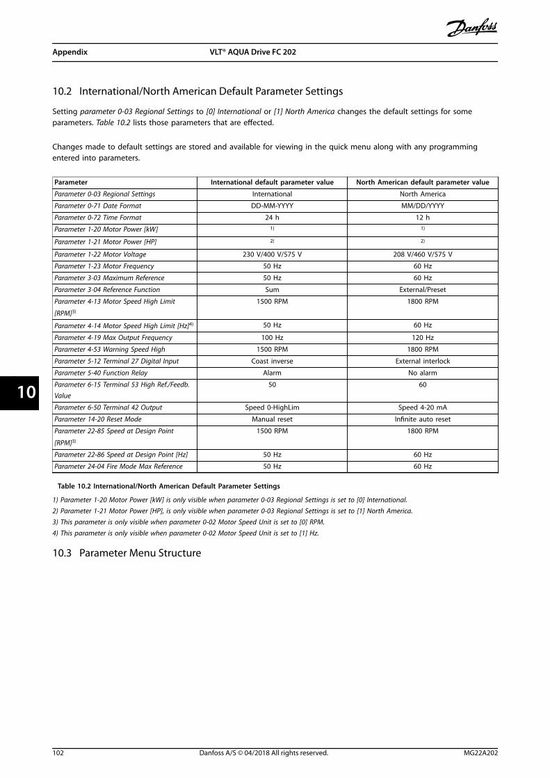
10.2 International/North American Default Parameter Settings
Setting parameter 0-03 Regional Settings to [0] International or [1] North America changes the default settings for someparameters. Table 10.2 lists those parameters that are effected.
Changes made to default settings are stored and available for viewing in the quick menu along with any programmingentered into parameters.
Parameter International default parameter value North American default parameter value
Parameter 0-03 Regional Settings International North America
Parameter 0-71 Date Format DD-MM-YYYY MM/DD/YYYY
Parameter 0-72 Time Format 24 h 12 h
Parameter 1-20 Motor Power [kW] 1) 1)
Parameter 1-21 Motor Power [HP] 2) 2)
Parameter 1-22 Motor Voltage 230 V/400 V/575 V 208 V/460 V/575 V
Parameter 1-23 Motor Frequency 50 Hz 60 Hz
Parameter 3-03 Maximum Reference 50 Hz 60 Hz
Parameter 3-04 Reference Function Sum External/Preset
Parameter 4-13 Motor Speed High Limit
[RPM]3)
1500 RPM 1800 RPM
Parameter 4-14 Motor Speed High Limit [Hz]4) 50 Hz 60 Hz
Parameter 4-19 Max Output Frequency 100 Hz 120 Hz
Parameter 4-53 Warning Speed High 1500 RPM 1800 RPM
Parameter 5-12 Terminal 27 Digital Input Coast inverse External interlock
Parameter 5-40 Function Relay Alarm No alarm
Parameter 6-15 Terminal 53 High Ref./Feedb.Value
50 60
Parameter 6-50 Terminal 42 Output Speed 0-HighLim Speed 4-20 mA
Parameter 14-20 Reset Mode Manual reset Infinite auto reset
Parameter 22-85 Speed at Design Point
[RPM]3)
1500 RPM 1800 RPM
Parameter 22-86 Speed at Design Point [Hz] 50 Hz 60 Hz
Parameter 24-04 Fire Mode Max Reference 50 Hz 60 Hz
Table 10.2 International/North American Default Parameter Settings
1) Parameter 1-20 Motor Power [kW] is only visible when parameter 0-03 Regional Settings is set to [0] International.2) Parameter 1-21 Motor Power [HP], is only visible when parameter 0-03 Regional Settings is set to [1] North America.3) This parameter is only visible when parameter 0-02 Motor Speed Unit is set to [0] RPM.4) This parameter is only visible when parameter 0-02 Motor Speed Unit is set to [1] Hz.
10.3 Parameter Menu Structure
Appendix VLT® AQUA Drive FC 202
102 Danfoss A/S © 04/2018 All rights reserved. MG22A202
1010
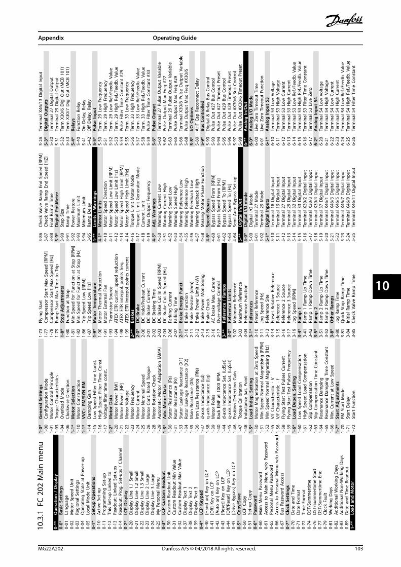
10.3
.1FC
202
Mai
n m
enu
0-**
Ope
ratio
n /
Dis
play
0-0*
Basi
c Se
ttin
gs0-
01La
ngua
ge0-
02M
otor
Spe
ed U
nit
0-03
Regi
onal
Set
tings
0-04
Ope
ratin
g S
tate
at
Pow
er-u
p0-
05Lo
cal M
ode
Uni
t0-
1*Se
t-up
Ope
ratio
ns0-
10Ac
tive
Set-
up0-
11Pr
ogra
mm
ing
Set
-up
0-12
This
Set
-up
Lin
ked
to
0-13
Read
out:
Lin
ked
Set
-ups
0-14
Read
out:
Pro
g. S
et-u
ps /
Cha
nnel
0-2*
LCP
Dis
play
0-20
Dis
play
Lin
e 1.
1 Sm
all
0-21
Dis
play
Lin
e 1.
2 Sm
all
0-22
Dis
play
Lin
e 1.
3 Sm
all
0-23
Dis
play
Lin
e 2
Larg
e0-
24D
ispl
ay L
ine
3 La
rge
0-25
My
Pers
onal
Men
u0-
3*LC
P C
usto
m R
eado
ut0-
30Cu
stom
Rea
dout
Uni
t0-
31Cu
stom
Rea
dout
Min
Val
ue0-
32Cu
stom
Rea
dout
Max
Val
ue0-
37D
ispl
ay T
ext
10-
38D
ispl
ay T
ext
20-
39D
ispl
ay T
ext
30-
4*LC
P K
eypa
d0-
40[H
and
on]
Key
on
LCP
0-41
[Off]
Key
on
LCP
0-42
[Aut
o o
n] K
ey o
n L
CP0-
43[R
eset
] Ke
y on
LCP
0-44
[Off/
Rese
t] K
ey o
n L
CP0-
45[D
rive
Bypa
ss]
Key
on L
CP0-
5*Co
py/S
ave
0-50
LCP
Cop
y0-
51Se
t-up
Cop
y0-
6*Pa
ssw
ord
0-60
Mai
n M
enu
Pas
swor
d0-
61Ac
cess
to
Mai
n M
enu
w/o
Pas
swor
d0-
65Pe
rson
al M
enu
Pas
swor
d0-
66Ac
cess
to
Per
sona
l Men
u w
/o P
assw
ord
0-67
Bus
Pass
wor
d A
cces
s0-
7*Cl
ock
Sett
ings
0-70
Dat
e an
d T
ime
0-71
Dat
e Fo
rmat
0-72
Tim
e Fo
rmat
0-74
DST
/Sum
mer
time
0-76
DST
/Sum
mer
time
Star
t0-
77D
ST/S
umm
ertim
e En
d0-
79Cl
ock
Faul
t0-
81W
orki
ng D
ays
0-82
Addi
tiona
l Wor
king
Day
s0-
83Ad
ditio
nal N
on-W
orki
ng D
ays
0-89
Dat
e an
d T
ime
Read
out
1-**
Load
and
Mot
or
1-0*
Gen
eral
Set
tings
1-00
Confi
gura
tion
Mod
e1-
01M
otor
Con
trol
Prin
cipl
e1-
03To
rque
Cha
ract
eris
tics
1-04
Ove
rload
Mod
e1-
06Cl
ockw
ise
Dire
ctio
n1-
1*M
otor
Sel
ectio
n1-
10M
otor
Con
stru
ctio
n1-
1*VV
C+ P
M/S
YN R
M1-
14D
ampi
ng G
ain
1-15
Low
Spe
ed F
ilter
Tim
e Co
nst.
1-16
Hig
h S
peed
Filt
er T
ime
Cons
t.1-
17Vo
ltage
filte
r tim
e co
nst.
1-2*
Mot
or D
ata
1-20
Mot
or P
ower
[kW
]1-
21M
otor
Pow
er [H
P]1-
22M
otor
Vol
tage
1-23
Mot
or F
requ
ency
1-24
Mot
or C
urre
nt1-
25M
otor
Nom
inal
Spe
ed1-
26M
otor
Con
t. R
ated
Tor
que
1-28
Mot
or R
otat
ion
Che
ck1-
29Au
tom
atic
Mot
or A
dapt
atio
n (A
MA
)1-
3*A
dv. M
otor
Dat
a1-
30St
ator
Res
ista
nce
(Rs)
1-31
Roto
r Re
sist
ance
(Rr)
1-33
Stat
or L
eaka
ge R
eact
ance
(X1)
1-34
Roto
r Le
akag
e Re
acta
nce
(X2)
1-35
Mai
n R
eact
ance
(Xh)
1-36
Iron
Los
s Re
sist
ance
(Rfe
)1-
37d-
axis
Indu
ctan
ce (L
d)1-
38q-
axis
Indu
ctan
ce (L
q)1-
39M
otor
Pol
es1-
40Ba
ck E
MF
at 1
000
RPM
1-44
d-ax
is In
duct
ance
Sat
. (Ld
Sat)
1-45
q-ax
is In
duct
ance
Sat
. (Lq
Sat)
1-46
Posi
tion
Det
ectio
n G
ain
1-47
Torq
ue C
alib
ratio
n1-
48In
duct
ance
Sat
. Poi
nt1-
5*Lo
ad In
dep.
Set
ting
1-50
Mot
or M
agne
tisat
ion
at
Zero
Spe
ed1-
51M
in S
peed
Nor
mal
Mag
netis
ing
[RPM
]1-
52M
in S
peed
Nor
mal
Mag
netis
ing
[Hz]
1-55
V/f
Char
acte
ristic
- V
1-56
V/f
Char
acte
ristic
- f
1-58
Flyi
ng S
tart
Tes
t Pu
lses
Cur
rent
1-59
Flyi
ng S
tart
Tes
t Pu
lses
Fre
quen
cy1-
6*Lo
ad D
epen
. Set
ting
1-60
Low
Spe
ed L
oad
Com
pens
atio
n1-
61H
igh
Spe
ed L
oad
Com
pens
atio
n1-
62Sl
ip C
ompe
nsat
ion
1-63
Slip
Com
pens
atio
n T
ime
Cons
tant
1-64
Reso
nanc
e D
ampi
ng1-
65Re
sona
nce
Dam
ping
Tim
e Co
nsta
nt1-
66M
in. C
urre
nt a
t Lo
w S
peed
1-7*
Star
t A
djus
tmen
ts1-
70PM
Sta
rt M
ode
1-71
Star
t D
elay
1-72
Star
t Fu
nctio
n
1-73
Flyi
ng S
tart
1-77
Com
pres
sor
Star
t M
ax S
peed
[RPM
]1-
78Co
mpr
esso
r St
art
Max
Spe
ed [H
z]1-
79Pu
mp
Sta
rt M
ax T
ime
to T
rip1-
8*St
op A
djus
tmen
ts1-
80Fu
nctio
n a
t St
op1-
81M
in S
peed
for
Func
tion
at
Stop
[RPM
]1-
82M
in S
peed
for
Func
tion
at
Stop
[Hz]
1-86
Trip
Spe
ed L
ow [R
PM]
1-87
Trip
Spe
ed L
ow [H
z]1-
9*M
otor
Tem
pera
ture
1-90
Mot
or T
herm
al P
rote
ctio
n1-
91M
otor
Ext
erna
l Fan
1-93
Ther
mis
tor
Sour
ce1-
94AT
EX E
TR c
ur.li
m. s
peed
redu
ctio
n1-
98AT
EX E
TR in
terp
ol. p
oint
s fr
eq.
1-99
ATEX
ETR
inte
rpol
poi
nts
curr
ent
2-**
Brak
es2-
0*D
C-Br
ake
2-00
DC
Hol
d/Pr
ehea
t Cu
rren
t2-
01D
C B
rake
Cur
rent
2-02
DC
Bra
king
Tim
e2-
03D
C B
rake
Cut
In S
peed
[RPM
]2-
04D
C B
rake
Cut
In S
peed
[Hz]
2-06
Park
ing
Cur
rent
2-07
Park
ing
Tim
e2-
1*Br
ake
Ener
gy F
unct
.2-
10Br
ake
Func
tion
2-11
Brak
e Re
sist
or (o
hm)
2-12
Brak
e Po
wer
Lim
it (k
W)
2-13
Brak
e Po
wer
Mon
itorin
g2-
15Br
ake
Chec
k2-
16AC
bra
ke M
ax. C
urre
nt2-
17O
ver-
volta
ge C
ontr
ol3-
**Re
fere
nce
/ Ra
mps
3-0*
Refe
renc
e Li
mits
3-02
Min
imum
Ref
eren
ce3-
03M
axim
um R
efer
ence
3-04
Refe
renc
e Fu
nctio
n3-
1*Re
fere
nces
3-10
Pres
et R
efer
ence
3-11
Jog
Spe
ed [H
z]3-
13Re
fere
nce
Site
3-14
Pres
et R
elat
ive
Refe
renc
e3-
15Re
fere
nce
1 So
urce
3-16
Refe
renc
e 2
Sour
ce3-
17Re
fere
nce
3 So
urce
3-19
Jog
Spe
ed [R
PM]
3-4*
Ram
p 1
3-41
Ram
p 1
Ram
p U
p T
ime
3-42
Ram
p 1
Ram
p D
own
Tim
e3-
5*Ra
mp
23-
51Ra
mp
2 R
amp
Up
Tim
e3-
52Ra
mp
2 R
amp
Dow
n T
ime
3-8*
Oth
er R
amps
3-80
Jog
Ram
p T
ime
3-81
Qui
ck S
top
Ram
p T
ime
3-84
Initi
al R
amp
Tim
e3-
85Ch
eck
Valv
e Ra
mp
Tim
e
3-86
Chec
k Va
lve
Ram
p E
nd S
peed
[RPM
]3-
87Ch
eck
Valv
e Ra
mp
End
Spe
ed [H
Z]3-
88Fi
nal R
amp
Tim
e3-
9*D
igita
l Pot
.Met
er3-
90St
ep S
ize
3-91
Ram
p T
ime
3-92
Pow
er R
esto
re3-
93M
axim
um L
imit
3-94
Min
imum
Lim
it3-
95Ra
mp
Del
ay4-
**Li
mits
/ W
arni
ngs
4-1*
Mot
or L
imits
4-10
Mot
or S
peed
Dire
ctio
n4-
11M
otor
Spe
ed L
ow L
imit
[RPM
]4-
12M
otor
Spe
ed L
ow L
imit
[Hz]
4-13
Mot
or S
peed
Hig
h L
imit
[RPM
]4-
14M
otor
Spe
ed H
igh
Lim
it [H
z]4-
16To
rque
Lim
it M
otor
Mod
e4-
17To
rque
Lim
it G
ener
ator
Mod
e4-
18Cu
rren
t Li
mit
4-19
Max
Out
put
Freq
uenc
y4-
5*A
dj. W
arni
ngs
4-50
War
ning
Cur
rent
Low
4-51
War
ning
Cur
rent
Hig
h4-
52W
arni
ng S
peed
Low
4-53
War
ning
Spe
ed H
igh
4-54
War
ning
Ref
eren
ce L
ow4-
55W
arni
ng R
efer
ence
Hig
h4-
56W
arni
ng F
eedb
ack
Low
4-57
War
ning
Fee
dbac
k H
igh
4-58
Mis
sing
Mot
or P
hase
Fun
ctio
n4-
6*Sp
eed
Byp
ass
4-60
Bypa
ss S
peed
Fro
m [R
PM]
4-61
Bypa
ss S
peed
Fro
m [H
z]4-
62By
pass
Spe
ed T
o [R
PM]
4-63
Bypa
ss S
peed
To
[Hz]
4-64
Sem
i-Aut
o B
ypas
s Se
t-up
5-**
Dig
ital I
n/O
ut5-
0*D
igita
l I/O
mod
e5-
00D
igita
l I/O
Mod
e5-
01Te
rmin
al 2
7 M
ode
5-02
Term
inal
29
Mod
e5-
1*D
igita
l Inp
uts
5-10
Term
inal
18
Dig
ital I
nput
5-11
Term
inal
19
Dig
ital I
nput
5-12
Term
inal
27
Dig
ital I
nput
5-13
Term
inal
29
Dig
ital I
nput
5-14
Term
inal
32
Dig
ital I
nput
5-15
Term
inal
33
Dig
ital I
nput
5-16
Term
inal
X30
/2 D
igita
l Inp
ut5-
17Te
rmin
al X
30/3
Dig
ital I
nput
5-18
Term
inal
X30
/4 D
igita
l Inp
ut5-
19Te
rmin
al 3
7 D
igita
l Inp
ut5-
20Te
rmin
al X
46/1
Dig
ital I
nput
5-21
Term
inal
X46
/3 D
igita
l Inp
ut5-
22Te
rmin
al X
46/5
Dig
ital I
nput
5-23
Term
inal
X46
/7 D
igita
l Inp
ut5-
24Te
rmin
al X
46/9
Dig
ital I
nput
5-25
Term
inal
X46
/11
Dig
ital I
nput
5-26
Term
inal
X46
/13
Dig
ital I
nput
5-3*
Dig
ital O
utpu
ts5-
30Te
rmin
al 2
7 D
igita
l Out
put
5-31
Term
inal
29
Dig
ital O
utpu
t5-
32Te
rm X
30/6
Dig
i Out
(MCB
101
)5-
33Te
rm X
30/7
Dig
i Out
(MCB
101
)5-
4*Re
lays
5-40
Func
tion
Rel
ay5-
41O
n D
elay
, Rel
ay5-
42O
ff D
elay
, Rel
ay5-
5*Pu
lse
Inpu
t5-
50Te
rm. 2
9 Lo
w F
requ
ency
5-51
Term
. 29
Hig
h F
requ
ency
5-52
Term
. 29
Low
Ref
./Fee
db. V
alue
5-53
Term
. 29
Hig
h R
ef./F
eedb
. Val
ue5-
54Pu
lse
Filte
r Ti
me
Cons
tant
#29
5-55
Term
. 33
Low
Fre
quen
cy5-
56Te
rm. 3
3 H
igh
Fre
quen
cy5-
57Te
rm. 3
3 Lo
w R
ef./F
eedb
. Val
ue5-
58Te
rm. 3
3 H
igh
Ref
./Fee
db. V
alue
5-59
Puls
e Fi
lter
Tim
e Co
nsta
nt #
335-
6*Pu
lse
Out
put
5-60
Term
inal
27
Puls
e O
utpu
t Va
riabl
e5-
62Pu
lse
Out
put
Max
Fre
q #
275-
63Te
rmin
al 2
9 Pu
lse
Out
put
Varia
ble
5-65
Puls
e O
utpu
t M
ax F
req
#29
5-66
Term
inal
X30
/6 P
ulse
Out
put
Varia
ble
5-68
Puls
e O
utpu
t M
ax F
req
#X3
0/6
5-8*
I/O O
ptio
ns5-
80A
HF
Cap
Rec
onne
ct D
elay
5-9*
Bus
Cont
rolle
d5-
90D
igita
l & R
elay
Bus
Con
trol
5-93
Puls
e O
ut #
27 B
us C
ontr
ol5-
94Pu
lse
Out
#27
Tim
eout
Pre
set
5-95
Puls
e O
ut #
29 B
us C
ontr
ol5-
96Pu
lse
Out
#29
Tim
eout
Pre
set
5-97
Puls
e O
ut #
X30/
6 Bu
s Co
ntro
l5-
98Pu
lse
Out
#X3
0/6
Tim
eout
Pre
set
6-**
Ana
log
In/O
ut6-
0*A
nalo
g I/
O M
ode
6-00
Live
Zer
o T
imeo
ut T
ime
6-01
Live
Zer
o T
imeo
ut F
unct
ion
6-1*
Ana
log
Inpu
t 53
6-10
Term
inal
53
Low
Vol
tage
6-11
Term
inal
53
Hig
h V
olta
ge6-
12Te
rmin
al 5
3 Lo
w C
urre
nt6-
13Te
rmin
al 5
3 H
igh
Cur
rent
6-14
Term
inal
53
Low
Ref
./Fee
db. V
alue
6-15
Term
inal
53
Hig
h R
ef./F
eedb
. Val
ue6-
16Te
rmin
al 5
3 Fi
lter
Tim
e Co
nsta
nt6-
17Te
rmin
al 5
3 Li
ve Z
ero
6-2*
Ana
log
Inpu
t 54
6-20
Term
inal
54
Low
Vol
tage
6-21
Term
inal
54
Hig
h V
olta
ge6-
22Te
rmin
al 5
4 Lo
w C
urre
nt6-
23Te
rmin
al 5
4 H
igh
Cur
rent
6-24
Term
inal
54
Low
Ref
./Fee
db. V
alue
6-25
Term
inal
54
Hig
h R
ef./F
eedb
. Val
ue6-
26Te
rmin
al 5
4 Fi
lter
Tim
e Co
nsta
nt
Appendix Operating Guide
MG22A202 Danfoss A/S © 04/2018 All rights reserved. 103
10 10

6-27
Term
inal
54
Live
Zer
o6-
3*A
nalo
g In
put
X30/
116-
30Te
rmin
al X
30/1
1 Lo
w V
olta
ge6-
31Te
rmin
al X
30/1
1 H
igh
Vol
tage
6-34
Term
. X30
/11
Low
Ref
./Fee
db. V
alue
6-35
Term
. X30
/11
Hig
h R
ef./F
eedb
. Val
ue6-
36Te
rm. X
30/1
1 Fi
lter
Tim
e Co
nsta
nt6-
37Te
rm. X
30/1
1 Li
ve Z
ero
6-4*
Ana
log
Inpu
t X3
0/12
6-40
Term
inal
X30
/12
Low
Vol
tage
6-41
Term
inal
X30
/12
Hig
h V
olta
ge6-
44Te
rm. X
30/1
2 Lo
w R
ef./F
eedb
. Val
ue6-
45Te
rm. X
30/1
2 H
igh
Ref
./Fee
db. V
alue
6-46
Term
. X30
/12
Filte
r Ti
me
Cons
tant
6-47
Term
. X30
/12
Live
Zer
o6-
5*A
nalo
g O
utpu
t 42
6-50
Term
inal
42
Out
put
6-51
Term
inal
42
Out
put
Min
Sca
le6-
52Te
rmin
al 4
2 O
utpu
t M
ax S
cale
6-53
Term
inal
42
Out
put
Bus
Cont
rol
6-54
Term
inal
42
Out
put
Tim
eout
Pre
set
6-55
Term
inal
42
Out
put
Filte
r6-
6*A
nalo
g O
utpu
t X3
0/8
6-60
Term
inal
X30
/8 O
utpu
t6-
61Te
rmin
al X
30/8
Min
. Sca
le6-
62Te
rmin
al X
30/8
Max
. Sca
le6-
63Te
rmin
al X
30/8
Out
put
Bus
Cont
rol
6-64
Term
inal
X30
/8 O
utpu
t Ti
meo
ut P
rese
t6-
7*A
nalo
g O
utpu
t X4
5/1
6-70
Term
inal
X45
/1 O
utpu
t6-
71Te
rmin
al X
45/1
Min
. Sca
le6-
72Te
rmin
al X
45/1
Max
. Sca
le6-
73Te
rmin
al X
45/1
Bus
Con
trol
6-74
Term
inal
X45
/1 O
utpu
t Ti
meo
ut P
rese
t6-
8*A
nalo
g O
utpu
t X4
5/3
6-80
Term
inal
X45
/3 O
utpu
t6-
81Te
rmin
al X
45/3
Min
. Sca
le6-
82Te
rmin
al X
45/3
Max
. Sca
le6-
83Te
rmin
al X
45/3
Bus
Con
trol
6-84
Term
inal
X45
/3 O
utpu
t Ti
meo
ut P
rese
t8-
**Co
mm
. and
Opt
ions
8-0*
Gen
eral
Set
tings
8-01
Cont
rol S
ite8-
02Co
ntro
l Sou
rce
8-03
Cont
rol T
imeo
ut T
ime
8-04
Cont
rol T
imeo
ut F
unct
ion
8-05
End-
of-T
imeo
ut F
unct
ion
8-06
Rese
t Co
ntro
l Tim
eout
8-07
Dia
gnos
is T
rigge
r8-
08Re
adou
t Fi
lterin
g8-
1*Co
ntro
l Set
tings
8-10
Cont
rol P
rofil
e8-
13Co
nfigu
rabl
e St
atus
Wor
d S
TW8-
14Co
nfigu
rabl
e Co
ntro
l Wor
d C
TW8-
17Co
nfigu
rabl
e A
larm
and
War
ning
wor
d8-
3*FC
Por
t Se
ttin
gs8-
30Pr
otoc
ol8-
31Ad
dres
s8-
32Ba
ud R
ate
8-33
Parit
y /
Stop
Bits
8-35
Min
imum
Res
pons
e D
elay
8-36
Max
Res
pons
e D
elay
8-37
Max
imum
Inte
r-Ch
ar D
elay
8-4*
FC M
C p
roto
col s
et8-
40Te
legr
am S
elec
tion
8-42
PCD
Writ
e Co
nfigu
ratio
n8-
43PC
D R
ead
Con
figur
atio
n8-
5*D
igita
l/Bus
8-50
Coas
ting
Sel
ect
8-51
Qui
ck S
top
Sel
ect
8-52
DC
Bra
ke S
elec
t8-
53St
art
Sele
ct8-
54Re
vers
ing
Sel
ect
8-55
Set-
up S
elec
t8-
56Pr
eset
Ref
eren
ce S
elec
t8-
7*BA
Cnet
8-70
BACn
et D
evic
e In
stan
ce8-
72M
S/TP
Max
Mas
ters
8-73
MS/
TP M
ax In
fo F
ram
es8-
74"I-
Am
" Se
rvic
e8-
75In
itial
isat
ion
Pas
swor
d8-
8*FC
Por
t D
iagn
ostic
s8-
80Bu
s M
essa
ge C
ount
8-81
Bus
Erro
r Co
unt
8-82
Slav
e M
essa
ge R
cvd
8-83
Slav
e Er
ror
Coun
t8-
9*Bu
s Jo
g /
Fee
dbac
k8-
90Bu
s Jo
g 1
Spe
ed8-
91Bu
s Jo
g 2
Spe
ed8-
94Bu
s Fe
edba
ck 1
8-95
Bus
Feed
back
28-
96Bu
s Fe
edba
ck 3
9-**
PRO
FIdr
ive
9-00
Setp
oint
9-07
Actu
al V
alue
9-15
PCD
Writ
e Co
nfigu
ratio
n9-
16PC
D R
ead
Con
figur
atio
n9-
18N
ode
Addr
ess
9-22
Tele
gram
Sel
ectio
n9-
23Pa
ram
eter
s fo
r Si
gnal
s9-
27Pa
ram
eter
Edi
t9-
28Pr
oces
s Co
ntro
l9-
31Sa
fe A
ddre
ss9-
44Fa
ult
Mes
sage
Cou
nter
9-45
Faul
t Co
de9-
47Fa
ult
Num
ber
9-52
Faul
t Si
tuat
ion
Cou
nter
9-53
Profi
bus
War
ning
Wor
d9-
63Ac
tual
Bau
d R
ate
9-64
Dev
ice
Iden
tifica
tion
9-65
Profi
le N
umbe
r9-
67Co
ntro
l Wor
d 1
9-68
Stat
us W
ord
19-
70Pr
ogra
mm
ing
Set
-up
9-71
Profi
bus
Save
Dat
a Va
lues
9-72
Profi
busD
riveR
eset
9-75
DO
Iden
tifica
tion
9-80
Defi
ned
Par
amet
ers
(1)
9-81
Defi
ned
Par
amet
ers
(2)
9-82
Defi
ned
Par
amet
ers
(3)
9-83
Defi
ned
Par
amet
ers
(4)
9-84
Defi
ned
Par
amet
ers
(5)
9-85
Defi
ned
Par
amet
ers
(6)
9-90
Chan
ged
Par
amet
ers
(1)
9-91
Chan
ged
Par
amet
ers
(2)
9-92
Chan
ged
Par
amet
ers
(3)
9-93
Chan
ged
Par
amet
ers
(4)
9-94
Chan
ged
Par
amet
ers
(5)
9-99
Profi
bus
Revi
sion
Cou
nter
10-*
*CA
N F
ield
bus
10-0
*Co
mm
on S
ettin
gs10
-00
CAN
Pro
toco
l10
-01
Baud
Rat
e Se
lect
10-0
2M
AC ID
10-0
5Re
adou
t Tr
ansm
it E
rror
Cou
nter
10-0
6Re
adou
t Re
ceiv
e Er
ror
Coun
ter
10-0
7Re
adou
t Bu
s O
ff C
ount
er10
-1*
Dev
iceN
et10
-10
Proc
ess
Dat
a Ty
pe S
elec
tion
10-1
1Pr
oces
s D
ata
Confi
g W
rite
10-1
2Pr
oces
s D
ata
Confi
g R
ead
10-1
3W
arni
ng P
aram
eter
10-1
4N
et R
efer
ence
10-1
5N
et C
ontr
ol10
-2*
COS
Filte
rs10
-20
COS
Filte
r 1
10-2
1CO
S Fi
lter
210
-22
COS
Filte
r 3
10-2
3CO
S Fi
lter
410
-3*
Para
met
er A
cces
s10
-30
Arr
ay In
dex
10-3
1St
ore
Dat
a Va
lues
10-3
2D
evic
enet
Rev
isio
n10
-33
Stor
e A
lway
s10
-34
Dev
iceN
et P
rodu
ct C
ode
10-3
9D
evic
enet
F P
aram
eter
s12
-**
Ethe
rnet
12-0
*IP
Set
tings
12-0
0IP
Add
ress
Ass
ignm
ent
12-0
1IP
Add
ress
12-0
2Su
bnet
Mas
k12
-03
Def
ault
Gat
eway
12-0
4D
HCP
Ser
ver
12-0
5Le
ase
Expi
res
12-0
6N
ame
Serv
ers
12-0
7D
omai
n N
ame
12-0
8H
ost
Nam
e12
-09
Phys
ical
Add
ress
12-1
*Et
hern
et L
ink
Para
met
ers
12-1
0Li
nk S
tatu
s12
-11
Link
Dur
atio
n12
-12
Auto
Neg
otia
tion
12-1
3Li
nk S
peed
12-1
4Li
nk D
uple
x12
-18
Supe
rvis
or M
AC12
-19
Supe
rvis
or IP
Add
r.12
-2*
Proc
ess
Dat
a
12-2
0Co
ntro
l Ins
tanc
e12
-21
Proc
ess
Dat
a Co
nfig
Writ
e12
-22
Proc
ess
Dat
a Co
nfig
Rea
d12
-27
Prim
ary
Mas
ter
12-2
8St
ore
Dat
a Va
lues
12-2
9St
ore
Alw
ays
12-3
*Et
herN
et/IP
12-3
0W
arni
ng P
aram
eter
12-3
1N
et R
efer
ence
12-3
2N
et C
ontr
ol12
-33
CIP
Rev
isio
n12
-34
CIP
Pro
duct
Cod
e12
-35
EDS
Para
met
er12
-37
COS
Inhi
bit
Tim
er12
-38
COS
Filte
r12
-4*
Mod
bus
TCP
12-4
0St
atus
Par
amet
er12
-41
Slav
e M
essa
ge C
ount
12-4
2Sl
ave
Exce
ptio
n M
essa
ge C
ount
12-8
*O
ther
Eth
erne
t Se
rvic
es12
-80
FTP
Ser
ver
12-8
1H
TTP
Ser
ver
12-8
2SM
TP S
ervi
ce12
-83
SNM
P A
gent
12-8
4Ad
dres
s Co
nflic
t D
etec
tion
12-8
5AC
D L
ast
Confl
ict
12-8
9Tr
ansp
aren
t So
cket
Cha
nnel
Por
t12
-9*
Adv
ance
d E
ther
net
Serv
ices
12-9
0Ca
ble
Dia
gnos
tic12
-91
MD
I-X12
-92
IGM
P S
noop
ing
12-9
3Ca
ble
Erro
r Le
ngth
12-9
4Br
oadc
ast
Stor
m P
rote
ctio
n12
-95
Inac
tivity
tim
eout
12-9
6Po
rt C
onfig
12-9
7Q
oS P
riorit
y12
-98
Inte
rfac
e Co
unte
rs12
-99
Med
ia C
ount
ers
13-*
*Sm
art
Logi
c13
-0*
SLC
Set
tings
13-0
0SL
Con
trol
ler
Mod
e13
-01
Star
t Ev
ent
13-0
2St
op E
vent
13-0
3Re
set
SLC
13-1
*Co
mpa
rato
rs13
-10
Com
para
tor
Ope
rand
13-1
1Co
mpa
rato
r O
pera
tor
13-1
2Co
mpa
rato
r Va
lue
13-1
*RS
Flip
Flo
ps13
-15
RS-F
F O
pera
nd S
13-1
6RS
-FF
Ope
rand
R13
-2*
Tim
ers
13-2
0SL
Con
trol
ler
Tim
er13
-4*
Logi
c Ru
les
13-4
0Lo
gic
Rule
Boo
lean
113
-41
Logi
c Ru
le O
pera
tor
113
-42
Logi
c Ru
le B
oole
an 2
13-4
3Lo
gic
Rule
Ope
rato
r 2
13-4
4Lo
gic
Rule
Boo
lean
3
13-5
*St
ates
13-5
1SL
Con
trol
ler
Even
t13
-52
SL C
ontr
olle
r Ac
tion
13-9
*U
ser
Defi
ned
Ale
rts
13-9
0A
lert
Trig
ger
13-9
1A
lert
Act
ion
13-9
2A
lert
Tex
t13
-9*
Use
r D
efine
d R
eado
uts
13-9
7A
lert
Ala
rm W
ord
13-9
8A
lert
War
ning
Wor
d13
-99
Ale
rt S
tatu
s W
ord
14-*
*Sp
ecia
l Fun
ctio
ns14
-0*
Inve
rter
Sw
itchi
ng14
-00
Switc
hing
Pat
tern
14-0
1Sw
itchi
ng F
requ
ency
14-0
3O
verm
odul
atio
n14
-04
PWM
Ran
dom
14-1
*M
ains
On/
Off
14-1
0M
ains
Fai
lure
14-1
1M
ains
Vol
tage
at
Mai
ns F
ault
14-1
2Fu
nctio
n a
t M
ains
Imba
lanc
e14
-16
Kin.
Bac
kup
Gai
n14
-2*
Rese
t Fu
nctio
ns14
-20
Rese
t M
ode
14-2
1Au
tom
atic
Res
tart
Tim
e14
-22
Ope
ratio
n M
ode
14-2
3Ty
peco
de S
ettin
g14
-25
Trip
Del
ay a
t To
rque
Lim
it14
-26
Trip
Del
ay a
t In
vert
er F
ault
14-2
8Pr
oduc
tion
Set
tings
14-2
9Se
rvic
e Co
de14
-3*
Curr
ent
Lim
it C
trl.
14-3
0Cu
rren
t Li
m C
trl,
Prop
ortio
nal G
ain
14-3
1Cu
rren
t Li
m C
trl,
Inte
grat
ion
Tim
e14
-32
Curr
ent
Lim
Ctr
l, Fi
lter
Tim
e14
-4*
Ener
gy O
ptim
isin
g14
-40
VT L
evel
14-4
1A
EO M
inim
um M
agne
tisat
ion
14-4
2M
inim
um A
EO F
requ
ency
14-4
3M
otor
Cos
phi
14-5
*En
viro
nmen
t14
-50
RFI F
ilter
14-5
1D
C L
ink
Com
pens
atio
n14
-52
Fan
Con
trol
14-5
3Fa
n M
onito
r14
-55
Out
put
Filte
r14
-56
Capa
cita
nce
Out
put
Filte
r14
-57
Indu
ctan
ce O
utpu
t Fi
lter
14-5
8Vo
ltage
Gai
n F
ilter
14-5
9Ac
tual
Num
ber
of In
vert
er U
nits
14-6
*A
uto
Der
ate
14-6
0Fu
nctio
n a
t O
ver
Tem
pera
ture
14-6
1Fu
nctio
n a
t In
vert
er O
verlo
ad14
-62
Inv.
Ove
rload
Der
ate
Curr
ent
14-8
*O
ptio
ns14
-80
Opt
ion
Sup
plie
d b
y Ex
tern
al 2
4VD
C14
-9*
Faul
t Se
ttin
gs14
-90
Faul
t Le
vel
Appendix VLT® AQUA Drive FC 202
104 Danfoss A/S © 04/2018 All rights reserved. MG22A202
1010

15-*
*D
rive
Info
rmat
ion
15-0
*O
pera
ting
Dat
a15
-00
Ope
ratin
g h
ours
15-0
1Ru
nnin
g H
ours
15-0
2kW
h C
ount
er15
-03
Pow
er U
p's
15-0
4O
ver
Tem
p's
15-0
5O
ver
Volt'
s15
-06
Rese
t kW
h C
ount
er15
-07
Rese
t Ru
nnin
g H
ours
Cou
nter
15-0
8N
umbe
r of
Sta
rts
15-1
*D
ata
Log
Set
tings
15-1
0Lo
ggin
g S
ourc
e15
-11
Logg
ing
Inte
rval
15-1
2Tr
igge
r Ev
ent
15-1
3Lo
ggin
g M
ode
15-1
4Sa
mpl
es B
efor
e Tr
igge
r15
-2*
His
tori
c Lo
g15
-20
His
toric
Log
: Eve
nt15
-21
His
toric
Log
: Val
ue15
-22
His
toric
Log
: Tim
e15
-23
His
toric
log:
Dat
e an
d T
ime
15-3
*A
larm
Log
15-3
0A
larm
Log
: Err
or C
ode
15-3
1A
larm
Log
: Val
ue15
-32
Ala
rm L
og: T
ime
15-3
3A
larm
Log
: Dat
e an
d T
ime
15-3
4A
larm
Log
: Set
poin
t15
-35
Ala
rm L
og: F
eedb
ack
15-3
6A
larm
Log
: Cur
rent
Dem
and
15-3
7A
larm
Log
: Pro
cess
Ctr
l Uni
t15
-4*
Dri
ve Id
entifi
catio
n15
-40
FC T
ype
15-4
1Po
wer
Sec
tion
15-4
2Vo
ltage
15-4
3So
ftw
are
Vers
ion
15-4
4O
rder
ed T
ypec
ode
Strin
g15
-45
Actu
al T
ypec
ode
Strin
g15
-46
Freq
uenc
y Co
nver
ter
Ord
erin
g N
o15
-47
Pow
er C
ard
Ord
erin
g N
o15
-48
LCP
Id N
o15
-49
SW ID
Con
trol
Car
d15
-50
SW ID
Pow
er C
ard
15-5
1Fr
eque
ncy
Conv
erte
r Se
rial N
umbe
r15
-53
Pow
er C
ard
Ser
ial N
umbe
r15
-54
Confi
g F
ile N
ame
15-5
8Sm
artS
tart
File
nam
e15
-59
File
nam
e15
-6*
Opt
ion
Iden
t15
-60
Opt
ion
Mou
nted
15-6
1O
ptio
n S
W V
ersi
on15
-62
Opt
ion
Ord
erin
g N
o15
-63
Opt
ion
Ser
ial N
o15
-70
Opt
ion
in S
lot
A15
-71
Slot
A O
ptio
n S
W V
ersi
on15
-72
Opt
ion
in S
lot
B15
-73
Slot
B O
ptio
n S
W V
ersi
on15
-74
Opt
ion
in S
lot
C0/E
015
-75
Slot
C0/
E0 O
ptio
n S
W V
ersi
on
15-7
6O
ptio
n in
Slo
t C1
/E1
15-7
7Sl
ot C
1/E1
Opt
ion
SW
Ver
sion
15-8
*O
pera
ting
Dat
a II
15-8
0Fa
n R
unni
ng H
ours
15-8
1Pr
eset
Fan
Run
ning
Hou
rs15
-9*
Para
met
er In
fo15
-92
Defi
ned
Par
amet
ers
15-9
3M
odifi
ed P
aram
eter
s15
-98
Driv
e Id
entifi
catio
n15
-99
Para
met
er M
etad
ata
16-*
*D
ata
Read
outs
16-0
*G
ener
al S
tatu
s16
-00
Cont
rol W
ord
16-0
1Re
fere
nce
[Uni
t]16
-02
Refe
renc
e [%
]16
-03
Stat
us W
ord
16-0
5M
ain
Act
ual V
alue
[%]
16-0
9Cu
stom
Rea
dout
16-1
*M
otor
Sta
tus
16-1
0Po
wer
[kW
]16
-11
Pow
er [h
p]16
-12
Mot
or V
olta
ge16
-13
Freq
uenc
y16
-14
Mot
or c
urre
nt16
-15
Freq
uenc
y [%
]16
-16
Torq
ue [N
m]
16-1
7Sp
eed
[RPM
]16
-18
Mot
or T
herm
al16
-20
Mot
or A
ngle
16-2
2To
rque
[%]
16-2
3M
otor
Sha
ft P
ower
[kW
]16
-24
Calib
rate
d S
tato
r Re
sist
ance
16-2
6Po
wer
Filt
ered
[kW
]16
-27
Pow
er F
ilter
ed [h
p]16
-3*
Dri
ve S
tatu
s16
-30
DC
Lin
k Vo
ltage
16-3
1Sy
stem
Tem
p.16
-32
Brak
e En
ergy
/s
16-3
3Br
ake
Ener
gy A
vera
ge16
-34
Hea
tsin
k Te
mp.
16-3
5In
vert
er T
herm
al16
-36
Inv.
Nom
. Cur
rent
16-3
7In
v. M
ax. C
urre
nt16
-38
SL C
ontr
olle
r St
ate
16-3
9Co
ntro
l Car
d T
emp.
16-4
0Lo
ggin
g B
uffer
Ful
l16
-49
Curr
ent
Faul
t So
urce
16-5
*Re
f. &
Fee
db.
16-5
0Ex
tern
al R
efer
ence
16-5
2Fe
edba
ck[U
nit]
16-5
3D
igi P
ot R
efer
ence
16-5
4Fe
edba
ck 1
[Uni
t]16
-55
Feed
back
2 [U
nit]
16-5
6Fe
edba
ck 3
[Uni
t]16
-58
PID
Out
put
[%]
16-5
9Ad
just
ed S
etpo
int
16-6
*In
puts
& O
utpu
ts16
-60
Dig
ital I
nput
16-6
1Te
rmin
al 5
3 Sw
itch
Set
ting
16-6
2A
nalo
g In
put
5316
-63
Term
inal
54
Switc
h S
ettin
g16
-64
Ana
log
Inpu
t 54
16-6
5A
nalo
g O
utpu
t 42
[mA
]16
-66
Dig
ital O
utpu
t [b
in]
16-6
7Pu
lse
Inpu
t #2
9 [H
z]16
-68
Puls
e In
put
#33
[Hz]
16-6
9Pu
lse
Out
put
#27
[Hz]
16-7
0Pu
lse
Out
put
#29
[Hz]
16-7
1Re
lay
Out
put
[bin
]16
-72
Coun
ter
A16
-73
Coun
ter
B16
-75
Ana
log
In X
30/1
116
-76
Ana
log
In X
30/1
216
-77
Ana
log
Out
X30
/8 [m
A]
16-7
8A
nalo
g O
ut X
45/1
[mA
]16
-79
Ana
log
Out
X45
/3 [m
A]
16-8
*Fi
eldb
us &
FC
Por
t16
-80
Fiel
dbus
CTW
116
-82
Fiel
dbus
REF
116
-84
Com
m. O
ptio
n S
TW16
-85
FC P
ort
CTW
116
-86
FC P
ort
REF
116
-89
Confi
gura
ble
Ala
rm/W
arni
ng W
ord
16-9
*D
iagn
osis
Rea
dout
s16
-90
Ala
rm W
ord
16-9
1A
larm
Wor
d 2
16-9
2W
arni
ng W
ord
16-9
3W
arni
ng W
ord
216
-94
Ext.
Sta
tus
Wor
d16
-95
Ext.
Sta
tus
Wor
d 2
16-9
6M
aint
enan
ce W
ord
18-*
*In
fo &
Rea
dout
s18
-0*
Mai
nten
ance
Log
18-0
0M
aint
enan
ce L
og: I
tem
18-0
1M
aint
enan
ce L
og: A
ctio
n18
-02
Mai
nten
ance
Log
: Tim
e18
-03
Mai
nten
ance
Log
: Dat
e an
d T
ime
18-3
*A
nalo
g R
eado
uts
18-3
0A
nalo
g In
put
X42/
118
-31
Ana
log
Inpu
t X4
2/3
18-3
2A
nalo
g In
put
X42/
518
-33
Ana
log
Out
X42
/7 [
V]
18-3
4A
nalo
g O
ut X
42/9
[V
]18
-35
Ana
log
Out
X42
/11
[V]
18-3
6A
nalo
g In
put
X48/
2 [m
A]
18-3
7Te
mp.
Inpu
t X4
8/4
18-3
8Te
mp.
Inpu
t X4
8/7
18-3
9Te
mp.
Inpu
t X4
8/10
18-5
*Re
f. &
Fee
db.
18-5
0Se
nsor
less
Rea
dout
[uni
t]18
-6*
Inpu
ts &
Out
puts
218
-60
Dig
ital I
nput
218
-7*
Rect
ifier
Sta
tus
18-7
0M
ains
Vol
tage
18-7
1M
ains
Fre
quen
cy18
-72
Mai
ns Im
bala
nce
18-7
5Re
ctifi
er D
C V
olt.
20-*
*D
rive
Clo
sed
Loo
p
20-0
*Fe
edba
ck20
-00
Feed
back
1 S
ourc
e20
-01
Feed
back
1 C
onve
rsio
n20
-02
Feed
back
1 S
ourc
e U
nit
20-0
3Fe
edba
ck 2
Sou
rce
20-0
4Fe
edba
ck 2
Con
vers
ion
20-0
5Fe
edba
ck 2
Sou
rce
Uni
t20
-06
Feed
back
3 S
ourc
e20
-07
Feed
back
3 C
onve
rsio
n20
-08
Feed
back
3 S
ourc
e U
nit
20-1
2Re
fere
nce/
Feed
back
Uni
t20
-2*
Feed
back
/Set
poin
t20
-20
Feed
back
Fun
ctio
n20
-21
Setp
oint
120
-22
Setp
oint
220
-23
Setp
oint
320
-6*
Sens
orle
ss20
-60
Sens
orle
ss U
nit
20-6
9Se
nsor
less
Info
rmat
ion
20-7
*PI
D A
utot
unin
g20
-70
Clos
ed L
oop
Typ
e20
-71
PID
Per
form
ance
20-7
2PI
D O
utpu
t Ch
ange
20-7
3M
inim
um F
eedb
ack
Leve
l20
-74
Max
imum
Fee
dbac
k Le
vel
20-7
9PI
D A
utot
unin
g20
-8*
PID
Bas
ic S
ettin
gs20
-81
PID
Nor
mal
/ In
vers
e Co
ntro
l20
-82
PID
Sta
rt S
peed
[RPM
]20
-83
PID
Sta
rt S
peed
[Hz]
20-8
4O
n R
efer
ence
Ban
dwid
th20
-9*
PID
Con
trol
ler
20-9
1PI
D A
nti W
indu
p20
-93
PID
Pro
port
iona
l Gai
n20
-94
PID
Inte
gral
Tim
e20
-95
PID
Diff
eren
tiatio
n T
ime
20-9
6PI
D D
iff. G
ain
Lim
it21
-**
Ext.
Clo
sed
Loo
p21
-0*
Ext.
CL
Aut
otun
ing
21-0
0Cl
osed
Loo
p T
ype
21-0
1PI
D P
erfo
rman
ce21
-02
PID
Out
put
Chan
ge21
-03
Min
imum
Fee
dbac
k Le
vel
21-0
4M
axim
um F
eedb
ack
Leve
l21
-09
PID
Aut
o T
unin
g21
-1*
Ext.
CL
1 Re
f./Fb
.21
-10
Ext.
1 R
ef./F
eedb
ack
Uni
t21
-11
Ext.
1 M
inim
um R
efer
ence
21-1
2Ex
t. 1
Max
imum
Ref
eren
ce21
-13
Ext.
1 R
efer
ence
Sou
rce
21-1
4Ex
t. 1
Fee
dbac
k So
urce
21-1
5Ex
t. 1
Set
poin
t21
-17
Ext.
1 R
efer
ence
[Uni
t]21
-18
Ext.
1 F
eedb
ack
[Uni
t]21
-19
Ext.
1 O
utpu
t [%
]21
-2*
Ext.
CL
1 PI
D21
-20
Ext.
1 N
orm
al/In
vers
e Co
ntro
l21
-21
Ext.
1 P
ropo
rtio
nal G
ain
21-2
2Ex
t. 1
Inte
gral
Tim
e
21-2
3Ex
t. 1
Diff
eren
tatio
n T
ime
21-2
4Ex
t. 1
Dif.
Gai
n L
imit
21-3
*Ex
t. C
L 2
Ref./
Fb.
21-3
0Ex
t. 2
Ref
./Fee
dbac
k U
nit
21-3
1Ex
t. 2
Min
imum
Ref
eren
ce21
-32
Ext.
2 M
axim
um R
efer
ence
21-3
3Ex
t. 2
Ref
eren
ce S
ourc
e21
-34
Ext.
2 F
eedb
ack
Sour
ce21
-35
Ext.
2 S
etpo
int
21-3
7Ex
t. 2
Ref
eren
ce [U
nit]
21-3
8Ex
t. 2
Fee
dbac
k [U
nit]
21-3
9Ex
t. 2
Out
put
[%]
21-4
*Ex
t. C
L 2
PID
21-4
0Ex
t. 2
Nor
mal
/Inve
rse
Cont
rol
21-4
1Ex
t. 2
Pro
port
iona
l Gai
n21
-42
Ext.
2 In
tegr
al T
ime
21-4
3Ex
t. 2
Diff
eren
tatio
n T
ime
21-4
4Ex
t. 2
Dif.
Gai
n L
imit
21-5
*Ex
t. C
L 3
Ref./
Fb.
21-5
0Ex
t. 3
Ref
./Fee
dbac
k U
nit
21-5
1Ex
t. 3
Min
imum
Ref
eren
ce21
-52
Ext.
3 M
axim
um R
efer
ence
21-5
3Ex
t. 3
Ref
eren
ce S
ourc
e21
-54
Ext.
3 F
eedb
ack
Sour
ce21
-55
Ext.
3 S
etpo
int
21-5
7Ex
t. 3
Ref
eren
ce [U
nit]
21-5
8Ex
t. 3
Fee
dbac
k [U
nit]
21-5
9Ex
t. 3
Out
put
[%]
21-6
*Ex
t. C
L 3
PID
21-6
0Ex
t. 3
Nor
mal
/Inve
rse
Cont
rol
21-6
1Ex
t. 3
Pro
port
iona
l Gai
n21
-62
Ext.
3 In
tegr
al T
ime
21-6
3Ex
t. 3
Diff
eren
tatio
n T
ime
21-6
4Ex
t. 3
Dif.
Gai
n L
imit
22-*
*A
ppl.
Func
tions
22-0
*M
isce
llane
ous
22-0
0Ex
tern
al In
terlo
ck D
elay
22-0
1Po
wer
Filt
er T
ime
22-2
*N
o-Fl
ow D
etec
tion
22-2
0Lo
w P
ower
Aut
o S
et-u
p22
-21
Low
Pow
er D
etec
tion
22-2
2Lo
w S
peed
Det
ectio
n22
-23
No-
Flow
Fun
ctio
n22
-24
No-
Flow
Del
ay22
-26
Dry
Pum
p F
unct
ion
22-2
7D
ry P
ump
Del
ay22
-28
No-
Flow
Low
Spe
ed [R
PM]
22-2
9N
o-Fl
ow L
ow S
peed
[Hz]
22-3
*N
o-Fl
ow P
ower
Tun
ing
22-3
0N
o-Fl
ow P
ower
22-3
1Po
wer
Cor
rect
ion
Fac
tor
22-3
2Lo
w S
peed
[RPM
]22
-33
Low
Spe
ed [H
z]22
-34
Low
Spe
ed P
ower
[kW
]22
-35
Low
Spe
ed P
ower
[HP]
22-3
6H
igh
Spe
ed [R
PM]
22-3
7H
igh
Spe
ed [H
z]22
-38
Hig
h S
peed
Pow
er [k
W]
22-3
9H
igh
Spe
ed P
ower
[HP]
Appendix Operating Guide
MG22A202 Danfoss A/S © 04/2018 All rights reserved. 105
10 10

22-4
*Sl
eep
Mod
e22
-40
Min
imum
Run
Tim
e22
-41
Min
imum
Sle
ep T
ime
22-4
2W
ake-
up S
peed
[RPM
]22
-43
Wak
e-up
Spe
ed [H
z]22
-44
Wak
e-up
Ref
./FB
Diff
eren
ce22
-45
Setp
oint
Boo
st22
-46
Max
imum
Boo
st T
ime
22-5
*En
d o
f Cu
rve
22-5
0En
d o
f Cu
rve
Func
tion
22-5
1En
d o
f Cu
rve
Del
ay22
-6*
Brok
en B
elt
Det
ectio
n22
-60
Brok
en B
elt
Func
tion
22-6
1Br
oken
Bel
t To
rque
22-6
2Br
oken
Bel
t D
elay
22-7
*Sh
ort
Cycl
e Pr
otec
tion
22-7
5Sh
ort
Cycl
e Pr
otec
tion
22-7
6In
terv
al b
etw
een
Sta
rts
22-7
7M
inim
um R
un T
ime
22-7
8M
inim
um R
un T
ime
Ove
rrid
e22
-79
Min
imum
Run
Tim
e O
verr
ide
Valu
e22
-8*
Flow
Com
pens
atio
n22
-80
Flow
Com
pens
atio
n22
-81
Squa
re-li
near
Cur
ve A
ppro
xim
atio
n22
-82
Wor
k Po
int
Calc
ulat
ion
22-8
3Sp
eed
at
No-
Flow
[RPM
]22
-84
Spee
d a
t N
o-Fl
ow [H
z]22
-85
Spee
d a
t D
esig
n P
oint
[RPM
]22
-86
Spee
d a
t D
esig
n P
oint
[Hz]
22-8
7Pr
essu
re a
t N
o-Fl
ow S
peed
22-8
8Pr
essu
re a
t Ra
ted
Spe
ed22
-89
Flow
at
Des
ign
Poi
nt22
-90
Flow
at
Rate
d S
peed
23-*
*Ti
me-
base
d F
unct
ions
23-0
*Ti
med
Act
ions
23-0
0O
N T
ime
23-0
1O
N A
ctio
n23
-02
OFF
Tim
e23
-03
OFF
Act
ion
23-0
4O
ccur
renc
e23
-1*
Mai
nten
ance
23-1
0M
aint
enan
ce It
em23
-11
Mai
nten
ance
Act
ion
23-1
2M
aint
enan
ce T
ime
Base
23-1
3M
aint
enan
ce T
ime
Inte
rval
23-1
4M
aint
enan
ce D
ate
and
Tim
e23
-1*
Mai
nten
ance
Res
et23
-15
Rese
t M
aint
enan
ce W
ord
23-1
6M
aint
enan
ce T
ext
23-5
*En
ergy
Log
23-5
0En
ergy
Log
Res
olut
ion
23-5
1Pe
riod
Sta
rt23
-53
Ener
gy L
og23
-54
Rese
t En
ergy
Log
23-6
*Tr
endi
ng23
-60
Tren
d V
aria
ble
23-6
1Co
ntin
uous
Bin
Dat
a23
-62
Tim
ed B
in D
ata
23-6
3Ti
med
Per
iod
Sta
rt
23-6
4Ti
med
Per
iod
Sto
p23
-65
Min
imum
Bin
Val
ue23
-66
Rese
t Co
ntin
uous
Bin
Dat
a23
-67
Rese
t Ti
med
Bin
Dat
a23
-8*
Payb
ack
Coun
ter
23-8
0Po
wer
Ref
eren
ce F
acto
r23
-81
Ener
gy C
ost
23-8
2In
vest
men
t23
-83
Ener
gy S
avin
gs23
-84
Cost
Sav
ings
24-*
*A
ppl.
Func
tions
224
-1*
Dri
ve B
ypas
s24
-10
Driv
e By
pass
Fun
ctio
n24
-11
Driv
e By
pass
Del
ay T
ime
25-*
*Ca
scad
e Co
ntro
ller
25-0
*Sy
stem
Set
tings
25-0
0Ca
scad
e Co
ntro
ller
25-0
2M
otor
Sta
rt25
-04
Pum
p C
yclin
g25
-05
Fixe
d L
ead
Pum
p25
-06
Num
ber
of P
umps
25-2
*Ba
ndw
idth
Set
tings
25-2
0St
agin
g B
andw
idth
25-2
1O
verr
ide
Band
wid
th25
-22
Fixe
d S
peed
Ban
dwid
th25
-23
SBW
Sta
ging
Del
ay25
-24
SBW
Des
tagi
ng D
elay
25-2
5O
BW T
ime
25-2
6D
esta
ge A
t N
o-Fl
ow25
-27
Stag
e Fu
nctio
n25
-28
Stag
e Fu
nctio
n T
ime
25-2
9D
esta
ge F
unct
ion
25-3
0D
esta
ge F
unct
ion
Tim
e25
-4*
Stag
ing
Set
tings
25-4
0Ra
mp
Dow
n D
elay
25-4
1Ra
mp
Up
Del
ay25
-42
Stag
ing
Thr
esho
ld25
-43
Des
tagi
ng T
hres
hold
25-4
4St
agin
g S
peed
[RPM
]25
-45
Stag
ing
Spe
ed [H
z]25
-46
Des
tagi
ng S
peed
[RPM
]25
-47
Des
tagi
ng S
peed
[Hz]
25-4
9St
agin
g P
rinci
ple
25-5
*A
ltern
atio
n S
ettin
gs25
-50
Lead
Pum
p A
ltern
atio
n25
-51
Alte
rnat
ion
Eve
nt25
-52
Alte
rnat
ion
Tim
e In
terv
al25
-53
Alte
rnat
ion
Tim
er V
alue
25-5
4A
ltern
atio
n P
rede
fined
Tim
e25
-55
Alte
rnat
e if
Load
< 5
0%25
-56
Stag
ing
Mod
e at
Alte
rnat
ion
25-5
8Ru
n N
ext
Pum
p D
elay
25-5
9Ru
n o
n M
ains
Del
ay25
-8*
Stat
us25
-80
Casc
ade
Stat
us25
-81
Pum
p S
tatu
s25
-82
Lead
Pum
p25
-83
Rela
y St
atus
25-8
4Pu
mp
ON
Tim
e
25-8
5Re
lay
ON
Tim
e25
-86
Rese
t Re
lay
Coun
ters
25-9
*Se
rvic
e25
-90
Pum
p In
terlo
ck25
-91
Man
ual A
ltern
atio
n26
-**
Ana
log
I/O
Opt
ion
26-0
*A
nalo
g I/
O M
ode
26-0
0Te
rmin
al X
42/1
Mod
e26
-01
Term
inal
X42
/3 M
ode
26-0
2Te
rmin
al X
42/5
Mod
e26
-1*
Ana
log
Inpu
t X4
2/1
26-1
0Te
rmin
al X
42/1
Low
Vol
tage
26-1
1Te
rmin
al X
42/1
Hig
h V
olta
ge26
-14
Term
. X42
/1 L
ow R
ef./F
eedb
. Val
ue26
-15
Term
. X42
/1 H
igh
Ref
./Fee
db. V
alue
26-1
6Te
rm. X
42/1
Filt
er T
ime
Cons
tant
26-1
7Te
rm. X
42/1
Liv
e Ze
ro26
-2*
Ana
log
Inpu
t X4
2/3
26-2
0Te
rmin
al X
42/3
Low
Vol
tage
26-2
1Te
rmin
al X
42/3
Hig
h V
olta
ge26
-24
Term
. X42
/3 L
ow R
ef./F
eedb
. Val
ue26
-25
Term
. X42
/3 H
igh
Ref
./Fee
db. V
alue
26-2
6Te
rm. X
42/3
Filt
er T
ime
Cons
tant
26-2
7Te
rm. X
42/3
Liv
e Ze
ro26
-3*
Ana
log
Inpu
t X4
2/5
26-3
0Te
rmin
al X
42/5
Low
Vol
tage
26-3
1Te
rmin
al X
42/5
Hig
h V
olta
ge26
-34
Term
. X42
/5 L
ow R
ef./F
eedb
. Val
ue26
-35
Term
. X42
/5 H
igh
Ref
./Fee
db. V
alue
26-3
6Te
rm. X
42/5
Filt
er T
ime
Cons
tant
26-3
7Te
rm. X
42/5
Liv
e Ze
ro26
-4*
Ana
log
Out
X42
/726
-40
Term
inal
X42
/7 O
utpu
t26
-41
Term
inal
X42
/7 M
in. S
cale
26-4
2Te
rmin
al X
42/7
Max
. Sca
le26
-43
Term
inal
X42
/7 B
us C
ontr
ol26
-44
Term
inal
X42
/7 T
imeo
ut P
rese
t26
-5*
Ana
log
Out
X42
/926
-50
Term
inal
X42
/9 O
utpu
t26
-51
Term
inal
X42
/9 M
in. S
cale
26-5
2Te
rmin
al X
42/9
Max
. Sca
le26
-53
Term
inal
X42
/9 B
us C
ontr
ol26
-54
Term
inal
X42
/9 T
imeo
ut P
rese
t26
-6*
Ana
log
Out
X42
/11
26-6
0Te
rmin
al X
42/1
1 O
utpu
t26
-61
Term
inal
X42
/11
Min
. Sca
le26
-62
Term
inal
X42
/11
Max
. Sca
le26
-63
Term
inal
X42
/11
Bus
Cont
rol
26-6
4Te
rmin
al X
42/1
1 Ti
meo
ut P
rese
t27
-**
Casc
ade
CTL
Opt
ion
27-0
*Co
ntro
l & S
tatu
s27
-01
Pum
p S
tatu
s27
-02
Man
ual P
ump
Con
trol
27-0
3Cu
rren
t Ru
ntim
e H
ours
27-0
4Pu
mp
Tot
al L
ifetim
e H
ours
27-1
*Co
nfigu
ratio
n27
-10
Casc
ade
Cont
rolle
r27
-11
Num
ber
Of
Driv
es27
-12
Num
ber
Of
Pum
ps
27-1
4Pu
mp
Cap
acity
27-1
6Ru
ntim
e Ba
lanc
ing
27-1
7M
otor
Sta
rter
s27
-18
Spin
Tim
e fo
r U
nuse
d P
umps
27-1
9Re
set
Curr
ent
Runt
ime
Hou
rs27
-2*
Band
wid
th S
ettin
gs27
-20
Nor
mal
Ope
ratin
g R
ange
27-2
1O
verr
ide
Lim
it27
-22
Fixe
d S
peed
Onl
y O
pera
ting
Ran
ge27
-23
Stag
ing
Del
ay27
-24
Des
tagi
ng D
elay
27-2
5O
verr
ide
Hol
d T
ime
27-2
7M
in S
peed
Des
tage
Del
ay27
-3*
Stag
ing
Spe
ed27
-30
Auto
Tun
e St
agin
g S
peed
s27
-31
Stag
e O
n S
peed
[RPM
]27
-32
Stag
e O
n S
peed
[Hz]
27-3
3St
age
Off
Spe
ed [R
PM]
27-3
4St
age
Off
Spe
ed [H
z]27
-4*
Stag
ing
Set
tings
27-4
0Au
to T
une
Stag
ing
Set
tings
27-4
1Ra
mp
Dow
n D
elay
27-4
2Ra
mp
Up
Del
ay27
-43
Stag
ing
Thr
esho
ld27
-44
Des
tagi
ng T
hres
hold
27-4
5St
agin
g S
peed
[RPM
]27
-46
Stag
ing
Spe
ed [H
z]27
-47
Des
tagi
ng S
peed
[RPM
]27
-48
Des
tagi
ng S
peed
[Hz]
27-4
9St
agin
g P
rinci
ple
27-5
*A
ltern
ate
Sett
ings
27-5
0Au
tom
atic
Alte
rnat
ion
27-5
1A
ltern
atio
n E
vent
27-5
2A
ltern
atio
n T
ime
Inte
rval
27-5
3A
ltern
atio
n T
imer
Val
ue27
-54
Alte
rnat
ion
At
Tim
e of
Day
27-5
5A
ltern
atio
n P
rede
fined
Tim
e27
-56
Alte
rnat
e Ca
paci
ty is
<27
-58
Run
Nex
t Pu
mp
Del
ay27
-6*
Dig
ital I
nput
s27
-60
Term
inal
X66
/1 D
igita
l Inp
ut27
-61
Term
inal
X66
/3 D
igita
l Inp
ut27
-62
Term
inal
X66
/5 D
igita
l Inp
ut27
-63
Term
inal
X66
/7 D
igita
l Inp
ut27
-64
Term
inal
X66
/9 D
igita
l Inp
ut27
-65
Term
inal
X66
/11
Dig
ital I
nput
27-6
6Te
rmin
al X
66/1
3 D
igita
l Inp
ut27
-7*
Conn
ectio
ns27
-70
Rela
y27
-9*
Read
outs
27-9
1Ca
scad
e Re
fere
nce
27-9
2%
Of
Tota
l Cap
acity
27-9
3Ca
scad
e O
ptio
n S
tatu
s27
-94
Casc
ade
Syst
em S
tatu
s27
-95
Adva
nced
Cas
cade
Rel
ay O
utpu
t [b
in]
27-9
6Ex
tend
ed C
asca
de R
elay
Out
put
[bin
]29
-**
Wat
er A
pplic
atio
n F
unct
ions
29-0
*Pi
pe F
ill29
-00
Pipe
Fill
Ena
ble
29-0
1Pi
pe F
ill S
peed
[RPM
]29
-02
Pipe
Fill
Spe
ed [H
z]29
-03
Pipe
Fill
Tim
e29
-04
Pipe
Fill
Rat
e29
-05
Fille
d S
etpo
int
29-0
6N
o-Fl
ow D
isab
le T
imer
29-0
7Fi
lled
set
poin
t de
lay
29-1
*D
erag
ging
Fun
ctio
n29
-10
Der
ag C
ycle
s29
-11
Der
ag a
t St
art/
Stop
29-1
2D
erag
ging
Run
Tim
e29
-13
Der
ag S
peed
[RPM
]29
-14
Der
ag S
peed
[Hz]
29-1
5D
erag
Off
Del
ay29
-2*
Der
ag P
ower
Tun
ing
29-2
0D
erag
Pow
er[k
W]
29-2
1D
erag
Pow
er[H
P]29
-22
Der
ag P
ower
Fac
tor
29-2
3D
erag
Pow
er D
elay
29-2
4Lo
w S
peed
[RPM
]29
-25
Low
Spe
ed [H
z]29
-26
Low
Spe
ed P
ower
[kW
]29
-27
Low
Spe
ed P
ower
[HP]
29-2
8H
igh
Spe
ed [R
PM]
29-2
9H
igh
Spe
ed [H
z]29
-30
Hig
h S
peed
Pow
er [k
W]
29-3
1H
igh
Spe
ed P
ower
[HP]
29-3
2D
erag
On
Ref
Ban
dwid
th29
-33
Pow
er D
erag
Lim
it29
-34
Cons
ecut
ive
Der
ag In
terv
al29
-35
Der
ag a
t Lo
cked
Rot
or29
-4*
Pre/
Post
Lub
e29
-40
Pre/
Post
Lub
e Fu
nctio
n29
-41
Pre
Lube
Tim
e29
-42
Post
Lub
e Ti
me
29-5
*Fl
ow C
onfir
mat
ion
29-5
0Va
lidat
ion
Tim
e29
-51
Verifi
catio
n T
ime
29-5
2Si
gnal
Los
t Ve
rifica
tion
Tim
e29
-53
Flow
Con
firm
atio
n M
ode
29-6
*Fl
ow M
eter
29-6
0Fl
ow M
eter
Mon
itor
29-6
1Fl
ow M
eter
Sou
rce
29-6
2Fl
ow M
eter
Uni
t29
-63
Tota
lized
Vol
ume
Uni
t29
-64
Actu
al V
olum
e U
nit
29-6
5To
taliz
ed V
olum
e29
-66
Actu
al V
olum
e29
-67
Rese
t To
taliz
ed V
olum
e29
-68
Rese
t Ac
tual
Vol
ume
29-6
9Fl
ow30
-**
Spec
ial F
eatu
res
30-2
*A
dv. S
tart
Adj
ust
30-2
2Lo
cked
Rot
or D
etec
tion
30-2
3Lo
cked
Rot
or D
etec
tion
Tim
e [s
]30
-5*
Uni
t Co
nfigu
ratio
n30
-50
Hea
t Si
nk F
an M
ode
30-8
*Co
mpa
tibili
ty (I
)30
-81
Brak
e Re
sist
or (o
hm)
Appendix VLT® AQUA Drive FC 202
106 Danfoss A/S © 04/2018 All rights reserved. MG22A202
1010

31-*
*By
pass
Opt
ion
31-0
0By
pass
Mod
e31
-01
Bypa
ss S
tart
Tim
e D
elay
31-0
2By
pass
Trip
Tim
e D
elay
31-0
3Te
st M
ode
Activ
atio
n31
-10
Bypa
ss S
tatu
s W
ord
31-1
1By
pass
Run
ning
Hou
rs31
-19
Rem
ote
Bypa
ss A
ctiv
atio
n35
-**
Sens
or In
put
Opt
ion
35-0
*Te
mp.
Inpu
t M
ode
35-0
0Te
rm. X
48/4
Tem
pera
ture
Uni
t35
-01
Term
. X48
/4 In
put
Type
35-0
2Te
rm. X
48/7
Tem
pera
ture
Uni
t35
-03
Term
. X48
/7 In
put
Type
35-0
4Te
rm. X
48/1
0 Te
mpe
ratu
re U
nit
35-0
5Te
rm. X
48/1
0 In
put
Type
35-0
6Te
mpe
ratu
re S
enso
r A
larm
Fun
ctio
n35
-1*
Tem
p. In
put
X48/
435
-14
Term
. X48
/4 F
ilter
Tim
e Co
nsta
nt35
-15
Term
. X48
/4 T
emp.
Mon
itor
35-1
6Te
rm. X
48/4
Low
Tem
p. L
imit
35-1
7Te
rm. X
48/4
Hig
h T
emp.
Lim
it35
-2*
Tem
p. In
put
X48/
735
-24
Term
. X48
/7 F
ilter
Tim
e Co
nsta
nt35
-25
Term
. X48
/7 T
emp.
Mon
itor
35-2
6Te
rm. X
48/7
Low
Tem
p. L
imit
35-2
7Te
rm. X
48/7
Hig
h T
emp.
Lim
it35
-3*
Tem
p. In
put
X48/
1035
-34
Term
. X48
/10
Filte
r Ti
me
Cons
tant
35-3
5Te
rm. X
48/1
0 Te
mp.
Mon
itor
35-3
6Te
rm. X
48/1
0 Lo
w T
emp.
Lim
it35
-37
Term
. X48
/10
Hig
h T
emp.
Lim
it35
-4*
Ana
log
Inpu
t X4
8/2
35-4
2Te
rm. X
48/2
Low
Cur
rent
35-4
3Te
rm. X
48/2
Hig
h C
urre
nt35
-44
Term
. X48
/2 L
ow R
ef./F
eedb
. Val
ue35
-45
Term
. X48
/2 H
igh
Ref
./Fee
db. V
alue
35-4
6Te
rm. X
48/2
Filt
er T
ime
Cons
tant
35-4
7Te
rm. X
48/2
Liv
e Ze
ro43
-**
Uni
t Re
adou
ts43
-0*
Com
pone
nt S
tatu
s43
-00
Com
pone
nt T
emp.
43-0
1Au
xilia
ry T
emp.
43-1
*Po
wer
Car
d S
tatu
s43
-10
HS
Tem
p. p
h.U
43-1
1H
S Te
mp.
ph.
V43
-12
HS
Tem
p. p
h.W
43-1
3PC
Fan
A S
peed
43-1
4PC
Fan
B S
peed
43-1
5PC
Fan
C S
peed
43-2
*Fa
n P
ow.C
ard
Sta
tus
43-2
0FP
C F
an A
Spe
ed43
-21
FPC
Fan
B S
peed
43-2
2FP
C F
an C
Spe
ed43
-23
FPC
Fan
D S
peed
43-2
4FP
C F
an E
Spe
ed43
-25
FPC
Fan
F S
peed
Appendix Operating Guide
MG22A202 Danfoss A/S © 04/2018 All rights reserved. 107
10 10

Index
AA53/A54 switches................................................................................... 9
Abbreviations...................................................................................... 101
AC mains.................................................................................................. 26see also Mains
ADN compliance..................................................................................... 3
AirflowConfigurations.................................................................................. 99Heat sink.............................................................................................. 14
AlarmsList of............................................................................................. 11, 62Log......................................................................................................... 11Types of................................................................................................ 61
Ambient conditionsOverview............................................................................................. 13Specifications.................................................................................... 78
AnalogInput specifications......................................................................... 79
Analog input/outputDescriptions and default settings.............................................. 41Terminal locations.............................................................................. 9
Approvals and certifications............................................................... 3
ATEX monitoring................................................................................... 13
Auto on.............................................................................................. 11, 59
Automatic energy optimization...................................................... 50
Automatic motor adaptation (AMA)Configuring........................................................................................ 51Warning............................................................................................... 67
Auxillary contacts................................................................................. 43
BBack-wall cooling.................................................................................. 14
BrakeLocation of terminals........................................................................ 7Status message................................................................................. 59Terminal torque rating................................................................. 100
Brake resistorTerminal locations.............................................................................. 9Warning............................................................................................... 65Wiring................................................................................................... 44Wiring schematic............................................................................. 23
Burst transient....................................................................................... 28
Bus termination switch.................................................................. 9, 43
CCables
Cable length and cross-section.................................................. 79Creating openings for............................................................. 16, 17Installation warning........................................................................ 20Mains.................................................................................................... 26Maximum number and size per phase..................................... 73Motor.................................................................................................... 24Routing......................................................................................... 40, 45Shielded............................................................................................... 21Specifications.................................................................................... 79
Capacitor storage................................................................................. 12
Circuit breakers............................................................................... 45, 82
Compressor functions......................................................................... 47
Condensation......................................................................................... 13
ControlCharacteristics................................................................................... 81
Control cardLocation................................................................................................. 9Overtemperature trip point......................................................... 73RS485 specifications....................................................................... 80Specifications.................................................................................... 81Warning............................................................................................... 68
Control input/outputDescriptions and default settings.............................................. 40
Control shelf..................................................................................... 7, 8, 9
Control wiring.......................................................................... 40, 42, 45
CoolingCheck list............................................................................................. 45Dust warning..................................................................................... 13Requirements.................................................................................... 14
CurrentInput..................................................................................................... 44Leakage............................................................................................... 28Limit...................................................................................................... 72
DDefinitions
Status messages............................................................................... 59
Depth measurements............................................................................ 6
Design guide............................................................................... 3, 14, 78
DigitalInput specifications......................................................................... 79Output specifications..................................................................... 80
Digital input/outputDescriptions and default settings.............................................. 41Terminal locations.............................................................................. 9
Discharge time......................................................................................... 4
Disconnect............................................................................ 7, 43, 46, 82
Disposal instruction............................................................................... 3
Index VLT® AQUA Drive FC 202
108 Danfoss A/S © 04/2018 All rights reserved. MG22A202

Door clearanceE1h......................................................................................................... 86E2h......................................................................................................... 90E3h......................................................................................................... 94E4h......................................................................................................... 98
Door/panel coverTorque rating................................................................................... 100
DriveClearance requirements................................................................ 14Definition............................................................................................... 6Dimensions........................................................................................... 6Initialization....................................................................................... 53Status.................................................................................................... 59
Duct cooling........................................................................................... 14
EElectrical specifications 380–480 V................................................ 73
Electrical specifications 525–690 V................................................ 75
Electronic thermal relay (ETR).......................................................... 20
EMC.............................................................................................. 20, 21, 22
Encoder.................................................................................................... 51
Energy efficiency class........................................................................ 78
Environment.................................................................................... 13, 78
Explosive atmosphere......................................................................... 13
Exterior dimensionsE1h......................................................................................................... 83E2h......................................................................................................... 87E3h......................................................................................................... 91E4h......................................................................................................... 95
External alarm reset............................................................................. 56
FFactory default settings...................................................................... 52
Fan power cardLocation............................................................................................. 7, 8Warning............................................................................................... 70
FansLocation................................................................................................. 8Required airflow............................................................................... 14Servicing.............................................................................................. 13Warning........................................................................................ 64, 69
Fault log................................................................................................... 11
Fieldbus.................................................................................................... 40
Filter........................................................................................................... 13
FPC................................................................................................................ 7see also Fan power card
FusesLocation............................................................................................. 7, 8Overcurrent protection.................................................................. 20Pre-start check list........................................................................... 45Specifications.................................................................................... 82Troubleshooting............................................................................... 72
GGases......................................................................................................... 13
Gland plateDescription......................................................................................... 15Dimensions for E1h......................................................................... 86Dimensions for E2h......................................................................... 90Dimensions for E3h......................................................................... 94Dimensions for E4h......................................................................... 98Torque rating................................................................................... 100
GroundCheck list............................................................................................. 45Connecting......................................................................................... 28Floating delta.................................................................................... 26Grounded delta................................................................................ 26Isolated main..................................................................................... 26Terminal torque rating................................................................. 100Terminals........................................................................................... 7, 8Warning............................................................................................... 67
HHand on............................................................................................. 11, 59
Heat sinkAccess panel torque rating........................................................ 100Cleaning....................................................................................... 13, 58E1h access panel dimensions...................................................... 85E2h access panel dimensions...................................................... 89E3h access panel dimensions...................................................... 93E4h access panel dimensions...................................................... 97Overtemperature trip point......................................................... 73Required airflow............................................................................... 14Warning.......................................................................... 65, 67, 68, 70
HeaterLocation............................................................................................. 7, 8Usage.................................................................................................... 13Wiring of.............................................................................................. 43Wiring schematic............................................................................. 23
Height measurements........................................................................... 6
High voltage............................................................................. 46, 65, 66
High voltage warning............................................................................ 4
Humidity.................................................................................................. 13
HVAC fan functions.............................................................................. 47
IIndicator lights....................................................................................... 61
Initial set-up............................................................................................ 46
Input specifications............................................................................. 79
Input voltage.......................................................................................... 46
Index Operating Guide
MG22A202 Danfoss A/S © 04/2018 All rights reserved. 109

InstallationCheck list............................................................................................. 45Electrical.............................................................................................. 20EMC-compliant.......................................................................... 22, 28Initialization....................................................................................... 53Load share/regeneration terminals........................................... 19Mechanical......................................................................................... 15Qualified personnel........................................................................... 4Quick setup........................................................................................ 50Requirements.................................................................................... 14Start up................................................................................................ 52Tools needed..................................................................................... 12
InterferenceEMC....................................................................................................... 21Radio....................................................................................................... 6
Interior views............................................................................................ 7
Interlock device..................................................................................... 42
Internal fault........................................................................................... 67
KKnockout panel..................................................................................... 84
LLabel.......................................................................................................... 12
LCPDisplay................................................................................................. 10Indicator lights.................................................................................. 11Location............................................................................................. 7, 8Menu..................................................................................................... 47Troubleshooting............................................................................... 71
Leakage current................................................................................ 4, 28
Lifting................................................................................................. 12, 14
Load shareLocation of terminals........................................................................ 8Terminal torque rating................................................................. 100Terminals............................................................................................... 8Warning.................................................................................................. 4Wiring schematic............................................................................. 23
Load sharing.................................................................................... 65, 66
Local control panel (LCP)................................................................... 10
MMain menu.............................................................................................. 47
MainsCables................................................................................................... 26Connecting......................................................................................... 26Shield...................................................................................................... 5Supply specifications...................................................................... 78Terminal torque rating................................................................. 100Terminals........................................................................................... 7, 8Warning............................................................................................... 66
Maintenance.................................................................................... 13, 58
ManualVersion number................................................................................... 3
MCT 10...................................................................................................... 50
MCT 10 Set-up Software.................................................................... 50
Measurements......................................................................................... 6
MenuDescriptions of.................................................................................. 47Keys....................................................................................................... 11
MotorCables............................................................................................ 20, 24Class protection................................................................................ 13Connecting......................................................................................... 24Data....................................................................................................... 72Output specifications..................................................................... 78Overheating....................................................................................... 63Rotation............................................................................................... 51Terminal torque rating................................................................. 100Terminals............................................................................................... 7Thermistor.......................................................................................... 57Troubleshooting........................................................................ 71, 72Warning................................................................................. 62, 63, 65Wiring schematic............................................................................. 23
Mounting configurations.................................................................. 14
NNameplate............................................................................................... 12
Navigation keys.............................................................................. 11, 48
OOpen loop
Programming example.................................................................. 48Wiring for speed control................................................................ 54
Optional equipment..................................................................... 42, 46
Overcurrent protection...................................................................... 20
Overvoltage............................................................................................ 72
PParameters....................................................................................... 47, 52
Pedestal.................................................................................................... 15
Periodic forming................................................................................... 12
Phase loss................................................................................................ 62
Pigtails...................................................................................................... 20
Potential equalization......................................................................... 28
Potentiometer........................................................................................ 41
Power cardLocation................................................................................................. 9Warning............................................................................................... 68
Power connection................................................................................ 20
Power rating................................................................................ 6, 12, 73
Programming......................................................................... 11, 48, 102
Programming guide............................................................................... 3
PumpsConfiguring........................................................................................ 47Functions............................................................................................ 47
Index VLT® AQUA Drive FC 202
110 Danfoss A/S © 04/2018 All rights reserved. MG22A202

QQualified personnel................................................................................ 4
Quick menu............................................................................ 11, 47, 102
RRamp-down time.................................................................................. 72
Ramp-up time........................................................................................ 72
Recycling.................................................................................................... 3
RegenerationLocation of terminals........................................................................ 7Terminal torque rating................................................................. 100Terminals............................................................................................... 8Wiring configuration....................................................................... 57
Regional settings.................................................................................. 52
RelaysLocation.......................................................................................... 9, 41Output specifications..................................................................... 81
Reset............................................................................................ 11, 61, 68
RFI........................................................................................ 7, 8, 26, 94, 98
RotorWarning............................................................................................... 69
RS485Configuring........................................................................................ 43Terminal description....................................................................... 41Wiring schematic............................................................................. 23
SSafe torque off
Operating guide.................................................................................. 3
Safe Torque OffTerminal location............................................................................. 41Warning........................................................................................ 68, 69Wiring of.............................................................................................. 43Wiring schematic............................................................................. 23
Safety instructions.................................................................... 4, 20, 46
Serial communicationCover torque rating...................................................................... 100Descriptions and default settings.............................................. 41Location................................................................................................. 9
Service...................................................................................................... 58
Set-up....................................................................................................... 11
ShieldingCables................................................................................................... 40Clamps................................................................................................. 20Mains....................................................................................................... 5RFI........................................................................................................ 7, 8RFI termination.......................................................................... 94, 98Twisted ends...................................................................................... 20
Short circuit............................................................................................ 64
Short circuit current rating (SCCR)................................................. 82
Sleep mode............................................................................................. 60
Software version number.................................................................... 3
Space heater............................................................................................. 7see also Heater
Start/stop................................................................................................. 55
Status message definitions............................................................... 59
STO............................................................................................................... 3see also Safe torque off
Storage..................................................................................................... 12
Supply voltage................................................................................ 46, 80
SwitchesA53 and A54....................................................................................... 79A53/A54............................................................................................... 44Brake resistor temperature........................................................... 44Bus termination................................................................................ 43Disconnect................................................................................... 46, 82
TTemperature........................................................................................... 13
TerminalsAnalog input/output...................................................................... 41Control locations......................................................................... 9, 40Digital input/output........................................................................ 41E1h dimensions (front and side views).................................... 30E2h dimensions (front and side views).................................... 32E3h dimensions (front and side views).................................... 34E4h dimensions (front and side views).................................... 37Relays.................................................................................................... 41Serial communication.................................................................... 41Terminal 37.................................................................................. 41, 42
Thermal protection................................................................................ 3
ThermistorCable routing..................................................................................... 40Terminal location............................................................................. 41Warning............................................................................................... 69Wiring configurations..................................................................... 57
Tools.......................................................................................................... 12
TorqueCharacteristic..................................................................................... 78Fastener rating................................................................................ 100Limit............................................................................................... 63, 72
Transducer............................................................................................... 41
TroubleshootingFuses..................................................................................................... 72LCP......................................................................................................... 71Mains.................................................................................................... 72Motor............................................................................................. 71, 72Warnings and alarms...................................................................... 62
UUL certification......................................................................................... 3
Unintended start..................................................................................... 4
USBPort location......................................................................................... 9Specifications.................................................................................... 82
Index Operating Guide
MG22A202 Danfoss A/S © 04/2018 All rights reserved. 111
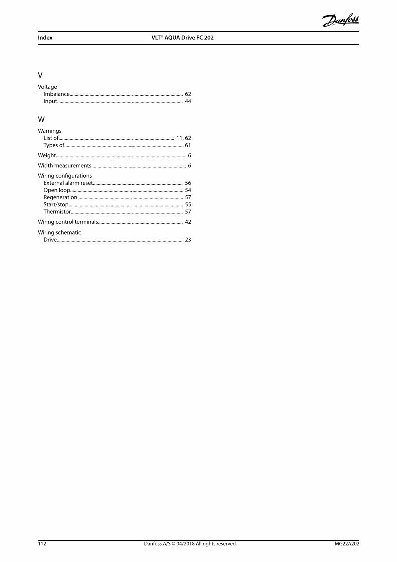
VVoltage
Imbalance........................................................................................... 62Input..................................................................................................... 44
WWarnings
List of............................................................................................. 11, 62Types of................................................................................................ 61
Weight......................................................................................................... 6
Width measurements............................................................................ 6
Wiring configurationsExternal alarm reset........................................................................ 56Open loop........................................................................................... 54Regeneration..................................................................................... 57Start/stop............................................................................................ 55Thermistor.......................................................................................... 57
Wiring control terminals.................................................................... 42
Wiring schematicDrive...................................................................................................... 23
Index VLT® AQUA Drive FC 202
112 Danfoss A/S © 04/2018 All rights reserved. MG22A202

Index Operating Guide
MG22A202 Danfoss A/S © 04/2018 All rights reserved. 113

Danfoss can accept no responsibility for possible errors in catalogues, brochures and other printed material. Danfoss reserves the right to alter its products without notice. This also applies toproducts already on order provided that such alterations can be made without subsequential changes being necessary in specifications already agreed. All trademarks in this material are propertyof the respective companies. Danfoss and the Danfoss logotype are trademarks of Danfoss A/S. All rights reserved.
Danfoss A/SUlsnaes 1DK-6300 Graastenvlt-drives.danfoss.com
*MG22A202*130R0708 MG22A202 04/2018