Embed Size (px)
Citation preview
Version 9211/b
Operating Guide SBK TwinCo 3000 distribution station Siegfried Böhnisch Kunststofftechnik GmbH Maybachstraße 1 D-74632 Neuenstein Tel +49(0)7942-944 926 0 Fax +49(0)7942-944 926 99 [email protected] www.sbk-neuenstein.de
Form
60e
ngl
Version 9211/b Seite 2
Table of contents Technical data .....................................................................................................................3
SBK Tempus control overview .............................................................................................4
Thermal functionality SBK TwinCo 3000 ……........................................................................5
Electric connection SBK Tempus control .........................................................................6
Service and modes of operation .........................................................................................8
Outside temperature controlled flow temperature setting diagram ........................................9
Constant flow temperature setting diagram ........................................................10
Function of the rotary knobs SBK Tempus control ................................................................11
Introduction ......................................................................................................................12
Mistake removal ...........................................................................................................14
Introduction security sheet ...........................................................................................15
Appendix individual parts cultivation sentence ..................................................................17
Appendix electric connection ……….......................….....................................................17
Accessories .......................................................................................................................18
Notice ...........................................................................................................................19
Version 9211/b Seite 3
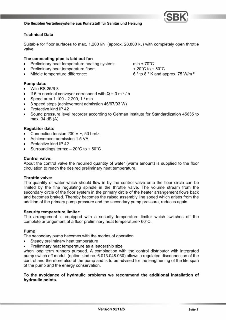
Technical Data Suitable for floor surfaces to max. 1,200 l/h (approx. 28,800 kJ) with completely open throttle valve. The connecting pipe is laid out for: • Preliminary heat temperature heating system: min + 70°C • Preliminary heat temperature floor: + 20°C to + 50°C • Middle temperature difference: 6 ° to 8 ° K and approx. 75 W/m ² Pump data: • Wilo RS 25/6-3 • If 6 m nominal conveyor correspond with Q = 0 m ³ / h • Speed area 1.100 - 2.200, 1 / min • 3 speed steps (achievement admission 46/67/93 W) • Protective kind IP 42 • Sound pressure level recorder according to German Institute for Standardization 45635 to
max. 34 dB (A) Regulator data: • Connection tension 230 V ~, 50 hertz • Achievement admission 1.5 VA • Protective kind IP 42 • Surroundings terms: – 20°C to + 50°C Control valve: About the control valve the required quantity of water (warm amount) is supplied to the floor circulation to reach the desired preliminary heat temperature. Throttle valve: The quantity of water which should flow in by the control valve onto the floor circle can be limited by the fine regulating spindle in the throttle valve. The volume stream from the secondary circle of the floor system in the primary circle of the heater arrangement flows back and becomes braked. Thereby becomes the raised assembly line speed which arises from the addition of the primary pump pressure and the secondary pump pressure, reduces again. Security temperature limiter: The arrangement is equipped with a security temperature limiter which switches off the complete arrangement at a floor preliminary heat temperature> 60°C. Pump: The secondary pump becomes with the modes of operation • Steady preliminary heat temperature • Preliminary heat temperature as a leadership size when long term runners pursued. A combination with the control distributor with integrated pump switch off modul (option kind no.:6.013.048.030) allows a regulated disconnection of the control and therefore also of the pump and is to be advised for the lengthening of the life span of the pump and the energy conservation. To the avoidance of hydraulic problems we recommend the additional installation of hydraulic points.
Version 9211/b Seite 4
SBK TEMPUS CONTROL Overview Tempus is a modern digital controller which combines the simple operation known from normal analogue devices with the precision and wide-ranging functions of a digital device. • Tempus controls the flow temperature based on the outside temperature with automatic
limitation of the maximum flow temperature. • Tempus can also be used as a fixed value controller, i.e. the set flow temperature is
adhered to precisely (standard model). • Tempus controls valves to set the afflux. The valves open and close slowly (approx. 5
minutes). The controller is optimal for use with underfloor heating. Integrated safety functions In addition, Tempus has numerous integrated safety functions to protect the system. • Safety temperature limitation
Every heating system should be secured by a double safety function, therefore a safety thermostat (safety temperature limiter) has also been integrated in addition to the safety functions of the controller to limit the maximum performance of the heating system.
• Anti-block logic for the pump
When the system is controlled by the outside temperature or boiler temperature, the pump switches off as soon as the outside temperature is approximately 1 °C higher than the set room temperature (control knob B). The pump is switched back on again as soon as the outside temperature drops approximately 2 °C below the set room temperature. If the outside temperature is higher than the room temperature for a longer period of time e.g. in the summer, the pump is switched off and only switched on again for a short period at fixed intervals to prevent the pump from getting stuck. If control knob C is turned to OFF, this function is activated automatically.
• Anti-blocking logic for valve
The valve is also switched on for a short period of time in the same way as the pump is in order to prevent it from getting stuck.
• Failure of a sensor
If the outside sensor is missing or has failed, the system automatically switches into the “constant flow temperature” mode. If the flow sensor is missing or has failed, the valve is controlled with the opening half open and therefore a basic heating is established for safety reasons.
Version 9211/b Seite 5
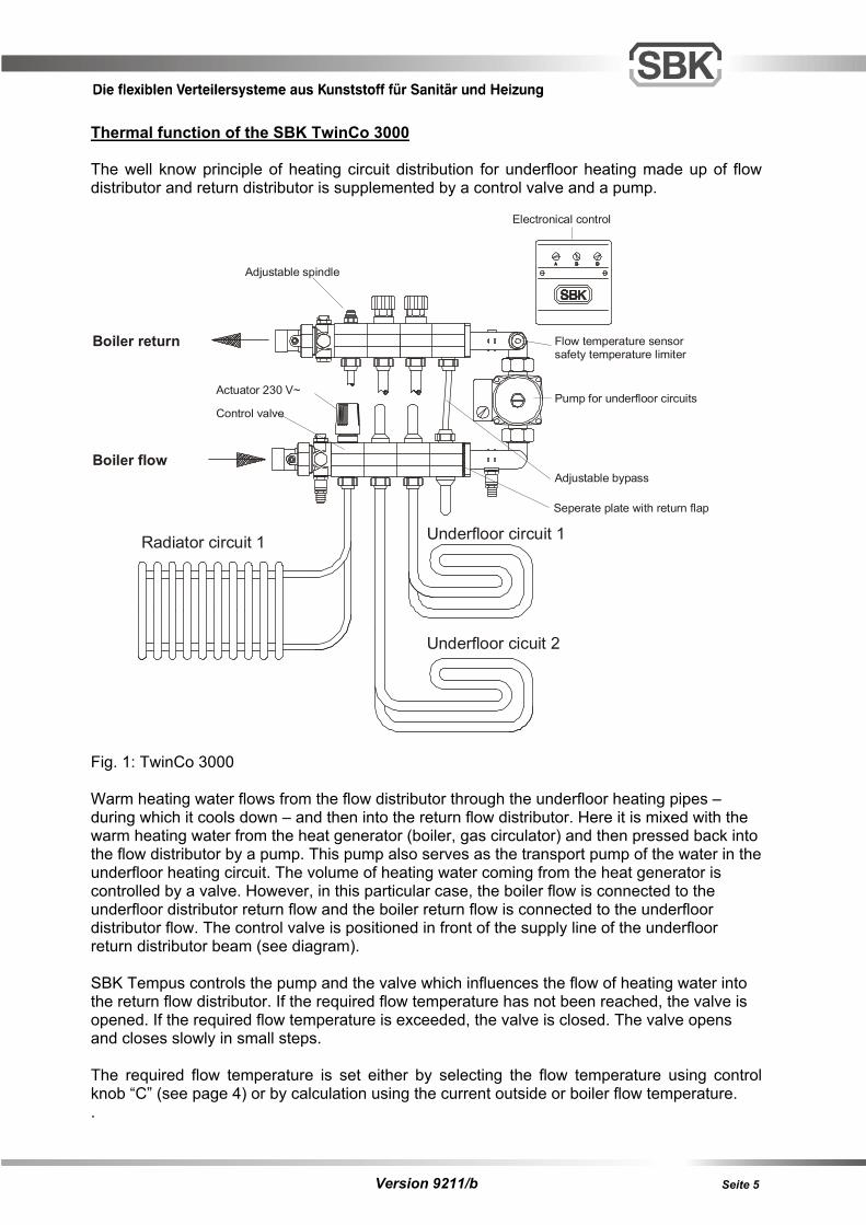
Thermal function of the SBK TwinCo 3000 The well know principle of heating circuit distribution for underfloor heating made up of flow distributor and return distributor is supplemented by a control valve and a pump.
Fig. 1: TwinCo 3000 Warm heating water flows from the flow distributor through the underfloor heating pipes – during which it cools down – and then into the return flow distributor. Here it is mixed with the warm heating water from the heat generator (boiler, gas circulator) and then pressed back into the flow distributor by a pump. This pump also serves as the transport pump of the water in the underfloor heating circuit. The volume of heating water coming from the heat generator is controlled by a valve. However, in this particular case, the boiler flow is connected to the underfloor distributor return flow and the boiler return flow is connected to the underfloor distributor flow. The control valve is positioned in front of the supply line of the underfloor return distributor beam (see diagram). SBK Tempus controls the pump and the valve which influences the flow of heating water into the return flow distributor. If the required flow temperature has not been reached, the valve is opened. If the required flow temperature is exceeded, the valve is closed. The valve opens and closes slowly in small steps. The required flow temperature is set either by selecting the flow temperature using control knob “C” (see page 4) or by calculation using the current outside or boiler flow temperature. .
Boiler flow
Boiler return
Seperate plate with return flap
Electronical control
Flow temperature sensorsafety temperature limiter
Pump for underfloor circuits
Adjustable bypass
Adjustable spindle
Underfloor circuit 1
Underfloor cicuit 2
Radiator circuit 1
Control valve
Actuator 230 V~
Version 9211/b Seite 6
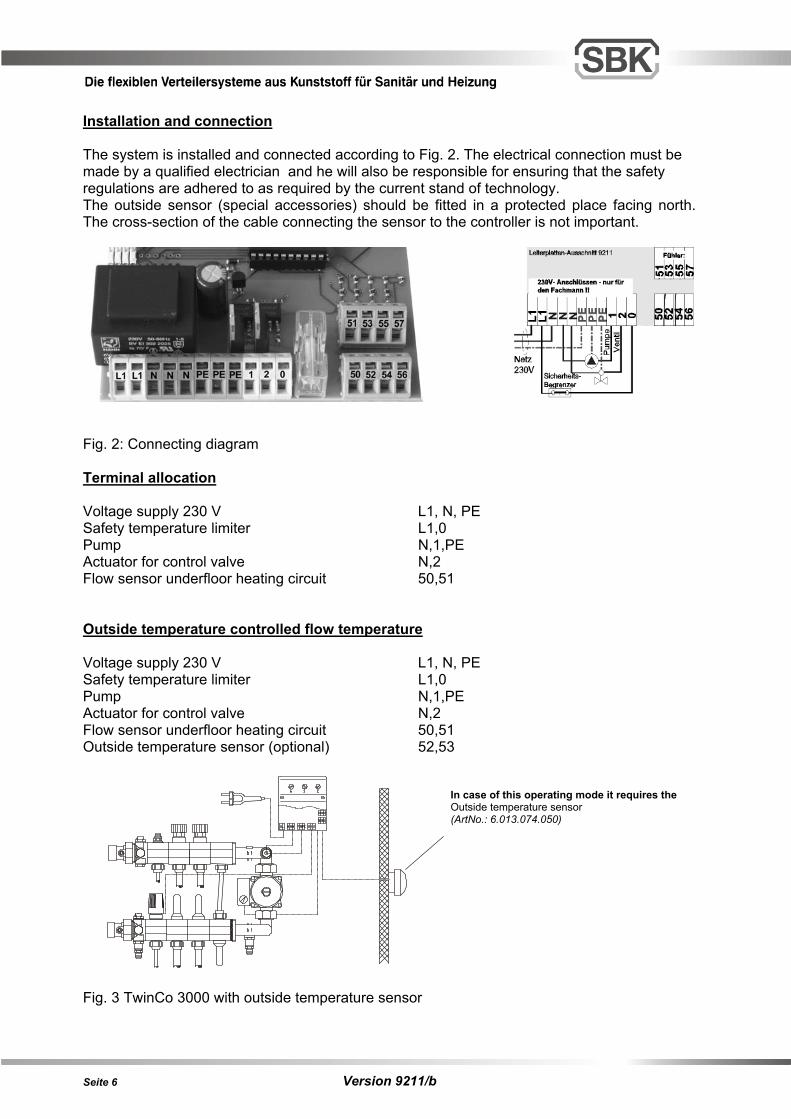
Installation and connection The system is installed and connected according to Fig. 2. The electrical connection must be made by a qualified electrician and he will also be responsible for ensuring that the safety regulations are adhered to as required by the current stand of technology. The outside sensor (special accessories) should be fitted in a protected place facing north. The cross-section of the cable connecting the sensor to the controller is not important.
Fig. 2: Connecting diagram Terminal allocation Voltage supply 230 V L1, N, PE Safety temperature limiter L1,0 Pump N,1,PE Actuator for control valve N,2 Flow sensor underfloor heating circuit 50,51 Outside temperature controlled flow temperature Voltage supply 230 V L1, N, PE Safety temperature limiter L1,0 Pump N,1,PE Actuator for control valve N,2 Flow sensor underfloor heating circuit 50,51 Outside temperature sensor (optional) 52,53
In case of this operating mode it requires the Outside temperature sensor (ArtNo.: 6.013.074.050) Fig. 3 TwinCo 3000 with outside temperature sensor
Version 9211/b Seite 7
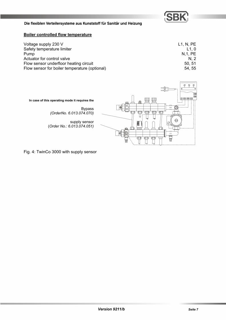
Boiler controlled flow temperature Voltage supply 230 V L1, N, PE Safety temperature limiter L1, 0 Pump N,1, PE Actuator for control valve N, 2 Flow sensor underfloor heating circuit 50, 51 Flow sensor for boiler temperature (optional) 54, 55
In case of this operating mode it requires the Bypass (OrderNo. 6.013.074.070) supply sensor (Order No.: 6.013.074.051) Fig. 4: TwinCo 3000 with supply sensor
Version 9211/b Seite 8
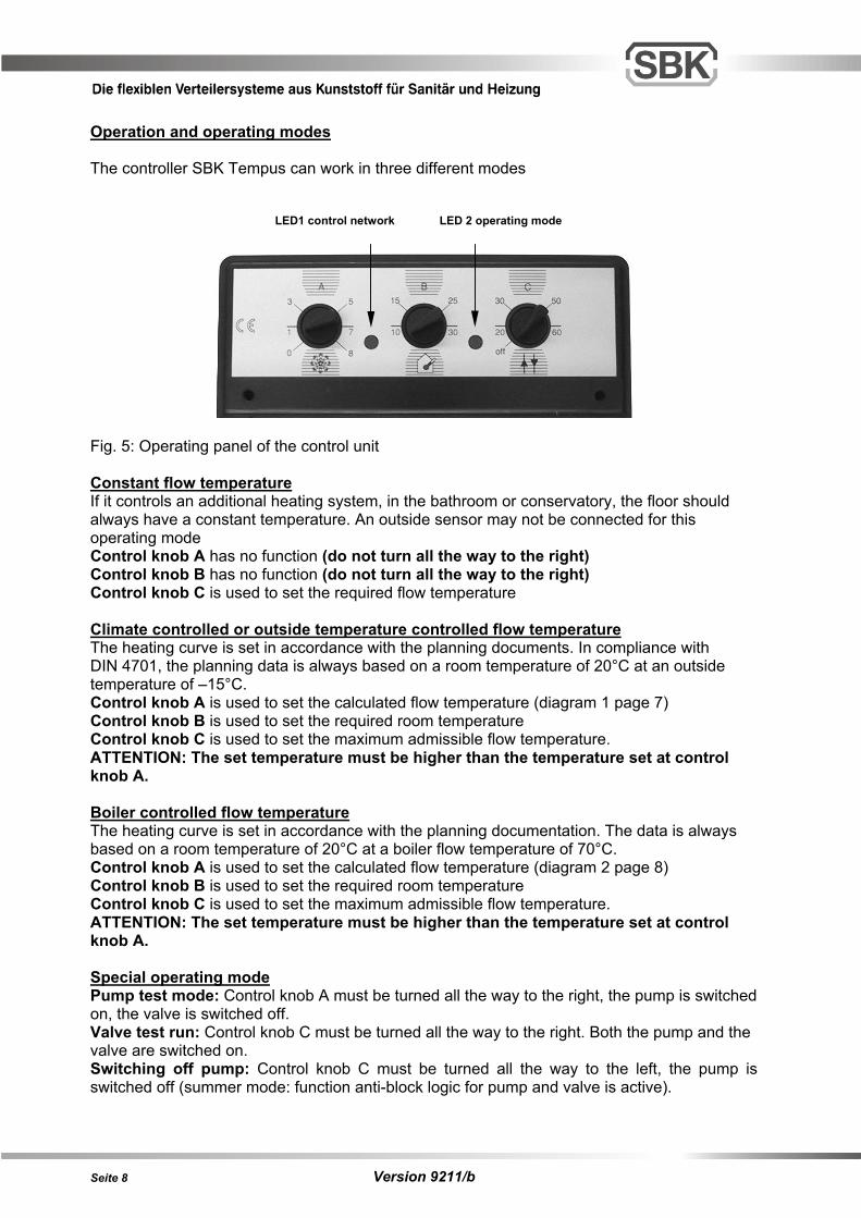
Operation and operating modes The controller SBK Tempus can work in three different modes LED1 control network LED 2 operating mode
Fig. 5: Operating panel of the control unit Constant flow temperature If it controls an additional heating system, in the bathroom or conservatory, the floor should always have a constant temperature. An outside sensor may not be connected for this operating mode Control knob A has no function (do not turn all the way to the right) Control knob B has no function (do not turn all the way to the right) Control knob C is used to set the required flow temperature Climate controlled or outside temperature controlled flow temperature The heating curve is set in accordance with the planning documents. In compliance with DIN 4701, the planning data is always based on a room temperature of 20°C at an outside temperature of –15°C. Control knob A is used to set the calculated flow temperature (diagram 1 page 7) Control knob B is used to set the required room temperature Control knob C is used to set the maximum admissible flow temperature. ATTENTION: The set temperature must be higher than the temperature set at control knob A. Boiler controlled flow temperature The heating curve is set in accordance with the planning documentation. The data is always based on a room temperature of 20°C at a boiler flow temperature of 70°C. Control knob A is used to set the calculated flow temperature (diagram 2 page 8) Control knob B is used to set the required room temperature Control knob C is used to set the maximum admissible flow temperature. ATTENTION: The set temperature must be higher than the temperature set at control knob A. Special operating mode Pump test mode: Control knob A must be turned all the way to the right, the pump is switched on, the valve is switched off. Valve test run: Control knob C must be turned all the way to the right. Both the pump and the valve are switched on. Switching off pump: Control knob C must be turned all the way to the left, the pump is switched off (summer mode: function anti-block logic for pump and valve is active).
Version 9211/b Seite 9
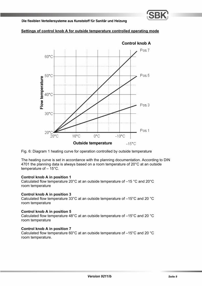
Settings of control knob A for outside temperature controlled operating mode Fig. 6: Diagram 1 heating curve for operation controlled by outside temperature The heating curve is set in accordance with the planning documentation. According to DIN 4701 the planning data is always based on a room temperature of 20°C at an outside temperature of – 15°C. Control knob A in position 1 Calculated flow temperature 20°C at an outside temperature of –15 °C and 20°C room temperature Control knob A in position 3 Calculated flow temperature 33°C at an outside temperature of –15°C and 20 °C room temperature Control knob A in position 5 Calculated flow temperature 48°C at an outside temperature of –15°C and 20 °C room temperature Control knob A in position 7 Calculated flow temperature 60°C at an outside temperature of –15°C and 20 °C room temperature.
Version 9211/b Seite 10
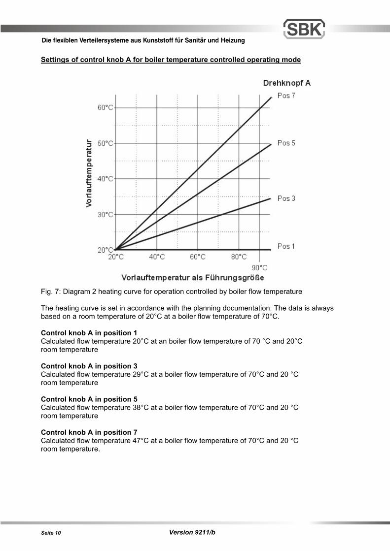
Settings of control knob A for boiler temperature controlled operating mode Fig. 7: Diagram 2 heating curve for operation controlled by boiler flow temperature The heating curve is set in accordance with the planning documentation. The data is always based on a room temperature of 20°C at a boiler flow temperature of 70°C. Control knob A in position 1 Calculated flow temperature 20°C at an boiler flow temperature of 70 °C and 20°C room temperature Control knob A in position 3 Calculated flow temperature 29°C at a boiler flow temperature of 70°C and 20 °C room temperature Control knob A in position 5 Calculated flow temperature 38°C at a boiler flow temperature of 70°C and 20 °C room temperature Control knob A in position 7 Calculated flow temperature 47°C at a boiler flow temperature of 70°C and 20 °C room temperature.
Version 9211/b Seite 11
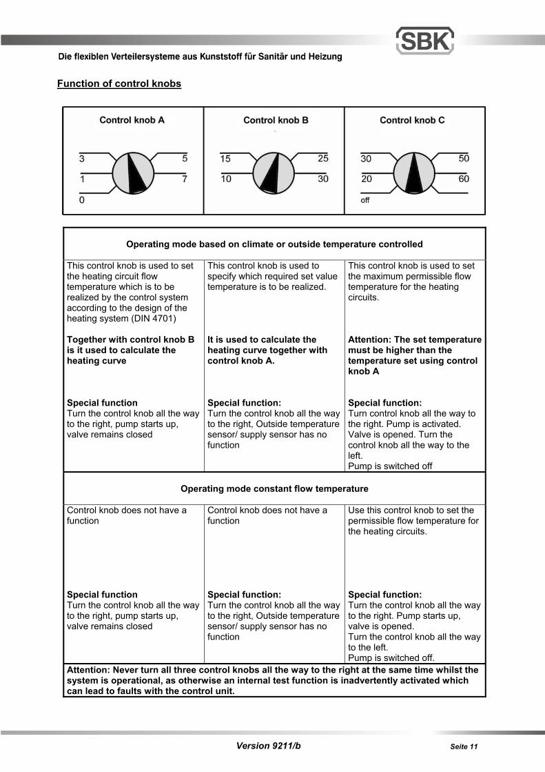
Function of control knobs
Operating mode based on climate or outside temperature controlled This control knob is used to set the heating circuit flow temperature which is to be realized by the control system according to the design of the heating system (DIN 4701) Together with control knob B is it used to calculate the heating curve Special function Turn the control knob all the way to the right, pump starts up, valve remains closed
This control knob is used to specify which required set value temperature is to be realized. It is used to calculate the heating curve together with control knob A. Special function: Turn the control knob all the way to the right, Outside temperature sensor/ supply sensor has no function
This control knob is used to set the maximum permissible flow temperature for the heating circuits. Attention: The set temperature must be higher than the temperature set using control knob A Special function: Turn control knob all the way to the right. Pump is activated. Valve is opened. Turn the control knob all the way to the left. Pump is switched off
Operating mode constant flow temperature
Control knob does not have a function Special function Turn the control knob all the way to the right, pump starts up, valve remains closed
Control knob does not have a function Special function: Turn the control knob all the way to the right, Outside temperature sensor/ supply sensor has no function
Use this control knob to set the permissible flow temperature for the heating circuits. Special function: Turn the control knob all the way to the right. Pump starts up, valve is opened. Turn the control knob all the way to the left. Pump is switched off.
Attention: Never turn all three control knobs all the way to the right at the same time whilst the system is operational, as otherwise an internal test function is inadvertently activated which can lead to faults with the control unit.
Version 9211/b Seite 12
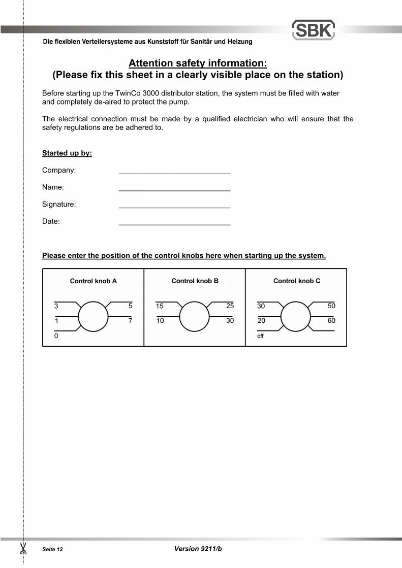
Attention safety information: (Please fix this sheet in a clearly visible place on the station)
Before starting up the TwinCo 3000 distributor station, the system must be filled with water and completely de-aired to protect the pump. The electrical connection must be made by a qualified electrician who will ensure that the safety regulations are be adhered to. Started up by: Company: ___________________________
Name: ___________________________
Signature: ___________________________
Date: ___________________________
Please enter the position of the control knobs here when starting up the system.
Version 9211/b Seite 13
Version 9211/b Seite 14
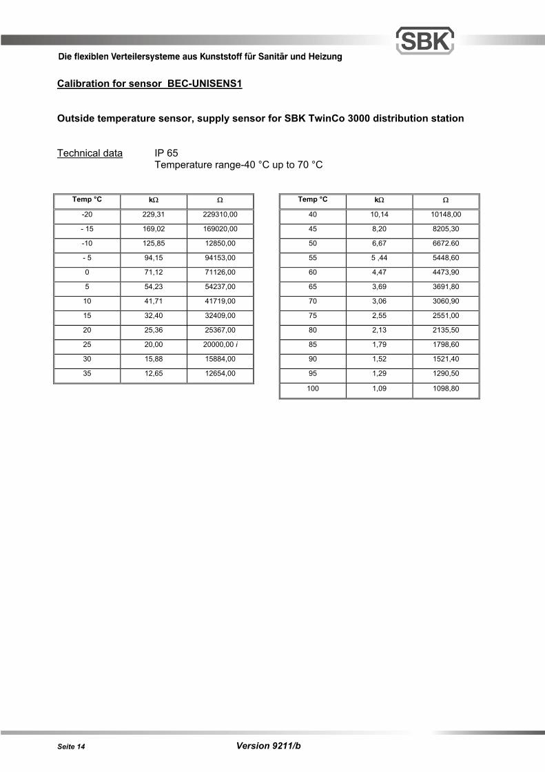
Calibration for sensor BEC-UNISENS1 Outside temperature sensor, supply sensor for SBK TwinCo 3000 distribution station Technical data IP 65 Temperature range-40 °C up to 70 °C
Temp °C kΩ Ω Temp °C kΩ Ω
-20 229,31 229310,00 40 10,14 10148,00
- 15 169,02 169020,00 45 8,20 8205,30
-10 125,85 12850,00 50 6,67 6672.60
- 5 94,15 94153,00 55 5 ,44 5448,60
0 71,12 71126,00 60 4,47 4473,90
5 54,23 54237,00 65 3,69 3691,80
10 41,71 41719,00 70 3,06 3060,90
15 32,40 32409,00 75 2,55 2551,00
20 25,36 25367,00 80 2,13 2135,50
25 20,00 20000,00 i 85 1,79 1798,60
30 15,88 15884,00 90 1,52 1521,40
35 12,65 12654,00 95 1,29 1290,50
100 1,09 1098,80
Version 9211/b Seite 15
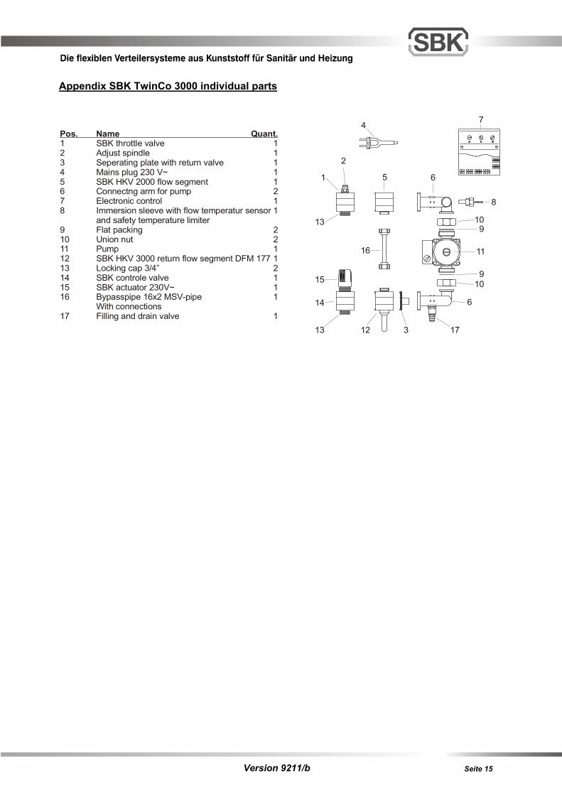
Appendix SBK TwinCo 3000 individual parts
Pos. Name Quant.1 SBK throttle valve 12 Adjust spindle 13 Seperating plate with return valve 14 Mains plug 230 V~ 15 SBK HKV 2000 flow segment 16 Connectng arm for pump 27 Electronic control 18 Immersion sleeve with flow temperatur sensor 1
and safety temperature limiter9 Flat packing 210 Union nut 211 Pump 112 SBK HKV 3000 return flow segment DFM 177 113 Locking cap 3/4” 214 SBK controle valve 115 SBK actuator 230V~ 116 Bypasspipe 16x2 MSV-pipe 1
With connections17 Filling and drain valve 1
1
3
4
5 6
7
8
910
11
1213
14
15
16
6
910
13
17
2
Version 9211/b Seite 16
Notice: