Embed Size (px)
Citation preview

FIBARO SMART IMPLANT
FGBS-222
O P E R A T I N GM A N U A L
EN
v1.2


3
Table of contents1: Important safety information 4
2: Description and features 5
2.1: Description 5
2.2: Main features 5
3: Specifications 6
4: Installation 7
4.1: Before installation 7
4.2: Connection with alarm line 9
4.3: Connection with DS18B20 10
4.4: Connection with DHT22 10
4.5: Connection with 2-wire 0-10V sensor 11
4.6: Connection with 3-wire 0-10V sensor 11
4.7: Connection with binary sensor 12
4.8: Connection with button 13
4.9: Connection with gate opener 14
5: Adding to Z-Wave network 15
5.1: Adding manually 15
5.2: Adding using Smart Start 15
6: Removing from Z-Wave network 16
7: Operating the device 17
7.1: Controlling the outputs 17
7.2: Visual indications 17
7.2: Menu 18
7.4: Resetting to factory defaults 18
8: Z-Wave range test 19
9: Activating scenes 20
10: Configuration 21
10.1: Associations 21
10.2: Advanced parameters 21
11: Z-Wave specification 29
12: Regulations 37

4
1: Important safety InformatIon
1: Important safety informationRead this manual before attempting to install the device!
! Failure to observe recommendations included in this manual may be dangerous or cause a violation of the law. The manu-
facturer, Fibar Group S.A. will not be held responsible for any loss or damage resulting from not following the instructions of operating manual.
Do not modify!
! Do not modify this device in any way not included in this man-ual. It might result in losing warranty privileges otherwise.
Other devices
! The manufacturer, Fibar Group S.A. will not be held responsi-ble for any damage or loss of warranty privileges for other con-
nected devices if the connection is not compliant with their manuals.
DANGER!The device is powered with a secure voltage. Nevertheless, the user should be careful or should commission the installation to
a qualified person.
DANGER!To avoid risk of electrical shock, do not operate the device with wet or moist hands.
This product is intended for indoor use only in dry locations.
! Do not use in damp or wet locations, near a bathtub, sink, shower, swimming pool, or anywhere else where water or
moisture are present.
Not a toy!
! This product is not a toy. Keep away from children and animals!

5
2: DescrIptIon anD features
2: Description and features
2.1: Description
FIBARO Smart Implant allows to enhance the functionality of wired sensors and other devices by adding Z-Wave network communication.
You can connect binary sensors, analog sensors, DS18B20 temper-ature sensors or DHT22 humidity and temperature sensor to report their readings to the Z-Wave controller.
It can also control devices by opening/closing output contacts inde-pendently of the inputs.
2.2: Main features
• Allows for connecting sensors:
» 6 DS18B20 sensors,
» 1 DHT sensor,
» 2 2-wire analog sensor,
» 2 3-wire analog sensor,
» 2 binary sensors.
• Built-in temperature sensor.
• Supports Z-Wave network Security Modes: S0 with AES-128 en-cryption and S2 Authenticated with PRNG-based encryption.
• Works as a Z-Wave signal repeater (all non-battery operated de-vices within the network will act as repeaters to increase reliabili-ty of the network).
• May be used with all devices certified with the Z-Wave Plus cer-tificate and should be compatible with such devices produced by other manufacturers.
i The device is a Security Enabled Z-Wave Plus product and a Security Enabled Z-Wave Controller must be
used in order to fully utilize the product.

6
3: specIfIcatIons
3: Specifications
Power supply 9-30V DC ±10%Inputs 2 0-10V or digital inputs
1 serial 1-wire inputOutputs 2 potential-free outputsSupported digital sensors 6 DS18B20 or 1 DHT22Maximum current on outputs 150mAMaximum voltage on outputs 30V DC / 20V AC ±5%Built-in temperature sensor measurement range
-55°C–126°C (-67°F–259°F)
Operating temperature 0–40°C (32–104°F)Radio protocol Z-Wave (500 series chip)Radio frequency 868.4 or 869.8 MHz EU;
908.4, 908.42 or 916.0 MHz US; 921.4 or 919.8 MHz ANZ; 869.0 MHz RU;
Transmit power EIRP max. 7dBmRange up to 50m (164 ft) outdoors
up to 40m (131 ft) indoors (depending on terrain and building structure)
Dimensions (Length x Width x Height)
29 x 18 x 13 mm (1.14” x 0.71” x 0.51”)
Compliance with EU directives RoHS 2011/65/EU RED 2014/53/EU
i Radio frequency of individual device must be same as your Z-Wave controller. Check information on the box
or consult your dealer if you are not sure.

7
4: InstallatIon
4: Installation
4.1: Before installation
! Connecting the device in a manner inconsistent with this manual may cause risk to health, life or material damage.
• Connect only in accordance with one of the diagrams,
• The device is powered with secure voltage; nevertheless, the user should be extra careful or should commission the installation to a qualified person,
• Do not connect devices which are not compliant with the specification,
• Do not connect other sensors than DS18B20 or DHT22 to SP and SD terminals,
• Do not connect sensors to SP and SD terminals with wires longer than 3 meters,
• Do not load the device outputs with a current exceeding 150mA,
• Every connected device should be compliant with the relevant safety standards,
• Unused lines should be left insulated.
Tips for arranging the antenna:• Locate the antenna as far from metal elements as possible (con-
necting wires, bracket rings, etc.) in order to prevent interferences,
• Metal surfaces in the direct vicinity of the antenna (e.g. flush mounted metal boxes, metal door frames) may impair signal reception!
• Do not cut or shorten the antenna - its length is perfectly matched to the band in which the system operates.
• Make sure no part of the antenna sticks out of the wall switch box.

8
4: InstallatIon
Notes for diagrams:
IN2IN1
GNDP
ANTGND
OUT2
OUT1
SDSP B
ANT (black) – antenna
GND (blue) – ground conductor
SD (white)– signal conductor for DS18B20 or DHT22 sensor
SP (brown) – power supply conductor for DS18B20 or DHT22 sensor (3.3V)
IN2 (green) – input no. 2
IN1 (yellow) – input no. 1
GND (blue) – ground conductor
P (red) – power supply conductor
OUT1 – output no. 1 assigned to input IN1
OUT2 – output no. 2 assigned to input IN2
B – service button (used to add/remove the device)

9
4: InstallatIon
4.2: Connection with alarm line
1. Turn off the alarm system.
2. Connect with one of the diagrams below:
Z1 Z2AUX COM
IN2IN1GNDP
COM 12VTMP TMPNCNC
1 2
Diagram 1: Example connection with regular alarm line
(1 – alarm sensor, 2 – alarm system hub)
COM 12VTMP TMP COM
R1
R2
Z1COM AUX
IN2IN1GNDP
NCNC
1 2
Diagram 2: Example connection with parametric alarm line
(1 – alarm sensor, 2 – alarm system hub)
3. Verify correctness of connection.
4. Arrange the device and its antenna in the housing.
5. Power the device.
6. Add the device to the Z-Wave network.
7. Change values of parameters:
• Connected to IN1:
» Normally close: change parameter 20 to 0
» Normally open: change parameter 20 to 1
• Connected to IN2:
» Normally close: change parameter 21 to 0
» Normally open: change parameter 21 to 1

10
4: InstallatIon
4.3: Connection with DS18B20
The DS18B20 sensor may easily be installed wherever very precise temperature measurements are required. If proper protective meas-ures are undertaken, the sensor may be used in humid environments or under water, it may be embedded in concrete or placed under the floor.
You can connect up to 6 DS18B20 sensors in parallel to SP-SD terminals.
1. Disconnect power.
2. Connect with the diagram below:VD
D
GN
D
GN
D
VDD
GND
DQ
DQ
SDSP
GND
GND 9-30V
P
12
Diagram 3: Example connection with 2 DS18B20 sensors
(1,2 – DS18B20 sensor)
3. Verify correctness of connection.
4. Power the device.
5. Add the device to the Z-Wave network.
4.4: Connection with DHT22
The DHT22 sensor may easily be installed wherever humidity and temperature measurements are required.
You can connect only 1 DHT22 sensor to TP-TD terminals.
1. Disconnect power.
2. Connect with the diagram below:
GND 9-30V
GNDSDSP
GNDP
GN
D
DAT
AVD
D
2
Diagram 4: Example connection with DHT22 sensor
(1 – DHT22 sensor)

11
4: InstallatIon
3. Verify correctness of connection.
4. Power the device.
5. Add the device to the Z-Wave network.
4.5: Connection with 2-wire 0-10V sensor
The 2-wire analog sensor requires pull-up resistor.
You can connect up to 2 analog sensors to IN1/IN2 terminals.
The 12V supply is required for these type of sensors.
1. Disconnect power.
2. Connect with the diagram below:
GND
IN2ANALOG OUT
GNDP
1
GND 12V
Diagram 5: Example connection with 2-wire analog sensor to IN2 input
(1 – 2-wire analog sensor)
3. Verify correctness of connection.
4. Power the device.
5. Add the device to the Z-Wave network.
6. Change values of parameters:
• Connected to IN1: change parameter 20 to 5
• Connected to IN2: change parameter 21 to 5
4.6: Connection with 3-wire 0-10V sensor
You can connect up to 2 analog sensors IN1/IN2 terminals.
1. Disconnect power.
2. Connect with the diagram below:
GNDIN1
P
VDDANALOG OUT
GND
1
GND 9-30V
Diagram 6: Example connection with 3-wire analog sensor to IN1 input
(1 – 3-wire analog sensor)

12
operatInG tHe DeVIce
3. Verify correctness of connection.
4. Power the device.
5. Add the device to the Z-Wave network.
6. Change values of parameters:
• Connected to IN1: change parameter 20 to 4
• Connected to IN2: change parameter 21 to 4
4.7: Connection with binary sensor
You connect normally opened or normally binary sensors to IN1/IN2 terminals.
1. Disconnect power.
2. Connect with the diagram below:
GND 9-30V
GNDIN1IN2
P
12
Diagram 7: Example connection with 2 binary sensors
(1,2 – binary sensor)
3. Verify correctness of connection.
4. Power the device.
5. Add the device to the Z-Wave network.
6. Change values of parameters:
• Connected to IN1:
» Normally close: change parameter 20 to 0
» Normally open: change parameter 20 to 1
• Connected to IN2:
» Normally close: change parameter 21 to 0
» Normally open: change parameter 21 to 1

13
4: InstallatIon
4.8: Connection with button
You can connect monostable or bistable switches to IN1/IN2 termi-nals to activate scenes.
1. Disconnect power.
2. Connect with the diagram below:
GND 9-30V
GNDIN1IN2
P
12
Diagram 8: Example connection with 2 buttons
(1,2 – button)
3. Verify correctness of connection.
4. Power the device.
5. Add the device to the Z-Wave network.
6. Change values of parameters:
• Connected to IN1:
» Monostable: change parameter 20 to 2
» Bistable: change parameter 20 to 3
• Connected to IN2:
» Monostable: change parameter 21 to 2
» Bistable: change parameter 21 to 3

14
4: InstallatIon
4.9: Connection with gate opener
Smart Implant can be connected to different devices to control them. In this example it is connected to gate opener with im-pulse input (every impulse will start and stop the gate motor, alternately opening/closing)
1. Disconnect power.
2. Connect with the diagram below:
OUT1IN1GNDP START/STOP
GND 2
1
GND 9-30V
Diagram 9: Example gate opener
(1 – monostable button, 2 – gate opener controller)
3. Verify correctness of connection.
4. Power the device.
5. Add the device to the Z-Wave network.
6. Change values of parameters:
• Connected to IN1 and OUT1:
» Change parameter 20 to 2 (monostable button)
» Change parameter 156 to 1 (0.1s)
• Connected to IN2 and OUT2:
» Change parameter 21 to 2 (monostable button)
» Change parameter 157 to 1 (0.1s)

15
5: aDDInG to Z-WaVe netWork
5: Adding to Z-Wave networkAdding (Inclusion) – Z-Wave device learning mode, allowing to add the device to existing Z-Wave network.
5.1: Adding manually
To add the device to the Z-Wave network manually:
1. Power the device.
2. Set the main controller in (Security/non-Security Mode) add mode (see the controller’s manual).
3. Quickly, triple click button on the device housing or switch connected to IN1 or IN2.
4. If you are adding in Security S2 Authenticated, scan the DSK QR code or input the 5-digit PIN code (label on the bottom of the box).
5. LED will start blinking yellow, wait for the adding process to end.
6. Successful adding will be confirmed by the Z-Wave controller’s message.
5.2: Adding using Smart Start
SmartStart enabled products can be added to SmartStart enabled Z-Wave controller by scanning the Z-Wave QR Code present on the product. SmartStart product will be added automatically within 10 minutes of being switched on in the network range.
To add the device to the Z-Wave network using Smart Start:
1. Set the main controller in Security S2 Authenticated add mode (see the controller’s manual).
2. Scan the DSK QR code or input the 5-digit PIN code (label on the bottom of the box).
3. Power the device.
4. LED will start blinking yellow, wait for the adding process to end.
5. Successful adding will be confirmed by the Z-Wave controller’s message.
i In case of problems with adding the device, please re-set the device and repeat the adding procedure.

16
6: remoVInG from Z-WaVe netWork
6: Removing from Z-Wave networkRemoving (Exclusion) – Z-Wave device learning mode, allowing to remove the device from existing Z-Wave network. Removing also re-sults in resetting the device to factory defaults.
To remove the device from the Z-Wave network:
1. Power the device.
2. Set the main controller into remove mode (see the controller’s manual).
3. Quickly, triple click button on the device housing or switch connected to IN1 or IN2.
4. LED will start blinking yellow, wait for the removing process to end.
5. Successful removing will be confirmed by the Z-Wave controller’s message.
i Removing using switch connected to IN1 or IN2 works only if parameter 20 (IN1) or 21 (IN2) is set to 2 or 3
and parameter 40 (IN1) or 41 (IN2) does not allow sending scenes for triple click.

17
7: operatInG tHe DeVIce
7: Operating the device
7.1: Controlling the outputs
It is possible to control the outputs with the inputs or with the B-button:
• single click – switch OUT1 output
• double click – switch OUT2 output
7.2: Visual indications
The built-in LED light shows current device status.
After powering the device:• Green – device added to a Z-Wave network (without Security S2
Authenticated)
• Magenta – device added to a Z-Wave network (with Security S2 Authenticated)
• Red – device not added to a Z-Wave network
Update:• Blinking cyan – update in progress
• Green – update successful (added without Security S2 Authenticated)
• Magenta – update successful (added with Security S2 Authenticated)
• Red – update not successful
Menu:• 3 green blinks – entering the menu (added without Security S2
Authenticated)
• 3 magenta blinks – entering the menu (added with Security S2 Authenticated)
• 3 red blinks – entering the menu (not added to a Z-Wave network)
• Magenta – range test
• Yellow – reset

18
7: operatInG tHe DeVIce
7.2: Menu
Menu allows to perform Z-Wave network actions. In order to use the menu:
1. Press and hold the button to enter the menu, device blinks to signal adding status (see 7.2: Visual indications).
2. Release the button when device signals desired position with colour:
• MAGENTA - start range test
• YELLOW - reset the device
3. Quickly click the button to confirm.
7.4: Resetting to factory defaults
Reset procedure allows to restore the device back to its factory set-tings, which means all information about the Z-Wave controller and user configuration will be deleted.
i Resetting the device is not the recommended way of removing the device from the Z-Wave network. Use re-
set procedure only if the primary controller is missing or inoperable. Certain device removal can be achieved by the procedure of removing described.
1. Press and hold the button to enter the menu.
2. Release button when the device glows yellow.
3. Quickly click the button to confirm.
4. After few seconds the device will be restarted, which is signalled with the red colour.

19
8: Z-WaVe ranGe test
8: Z-Wave range testThe device has a built in Z-Wave network main controller’s range tester.
i To make Z-Wave range test possible, the device must be added to the Z-Wave controller. Testing may stress
the network, so it is recommended to perform the test only in special cases.
To test the main controller’s range: 1. Press and hold the button to enter the menu.
2. Release button when the device glows magenta.
3. Quickly click the button to confirm.
4. Visual indicator will indicate the Z-Wave network’s range (range signaling modes described below).
5. To exit Z-Wave range test, press the button briefly.
Z-Wave range tester signalling modes:• Visual indicator pulsing green - the device attempts to establish
a direct communication with the main controller. If a direct com-munication attempt fails, the device will try to establish a routed communication, through other modules, which will be signalled by visual indicator pulsing yellow.
• Visual indicator glowing green - the device communicates with the main controller directly.
• Visual indicator pulsing yellow - the device tries to establish a routed communication with the main controller through other modules (repeaters).
• Visual indicator glowing yellow - the device communicates with the main controller through the other modules. After 2 seconds the device will retry to establish a direct communication with the main controller, which will be signalled with visual indicator puls-ing green.
• Visual indicator pulsing violet - the device does communicate at the maximum distance of the Z-Wave network. If connection proves successful it will be confirmed with a yellow glow. It’s not recommended to use the device at the range limit.
• Visual indicator glowing red - the device is not able to connect to the main controller directly or through another Z-Wave net-work device (repeater).
i Communication mode of the device may switch be-tween direct and one using routing, especially if the
device is on the limit of the direct range.

20
9: actIVatInG scenes
9: Activating scenesThe device can activate scenes in the Z-Wave controller by sending scene ID and attribute of a specific action using Central Scene Com-mand Class.
In order for this functionality to work connect monostable or bistable switch to the IN1 or IN2 input and set parameter 20 (IN1) or 21 (IN2) to 2 or 3.
By default scenes are not activated, set parameters 40 and 41 to en-able scene activation for selected actions.
Switch Action Scene ID Attribute
Switc
h co
nnec
ted
to
IN1
term
inal
Switch clicked once 1 Key Pressed 1 time
Switch clicked twice 1 Key Pressed 2 times
Switch clicked thrice* 1 Key Pressed 3 times
Switch held** 1 Key Held DownSwitch released** 1 Key Released
Switc
h co
nnec
ted
to
IN2
term
inal
Switch clicked once 2 Key Pressed 1 time
Switch clicked twice 2 Key Pressed 2 times
Switch clicked thrice* 2 Key Pressed 3 times
Switch held** 2 Key Held DownSwitch released** 2 Key Released
* Activating triple clicks will disallow removing using input terminal.
** Not available for toggle switches.

21
10: confIGuratIon
10: Configuration
10.1: Associations
Association (linking devices) - direct control of other devices within the Z-Wave system network e.g. Dimmer, Relay Switch, Roller Shutter or scene (may be controlled only through a Z-Wave controller).
Association ensures direct transfer of control commands between devices, is performed without participation of the main controller and requires associated device to be in the direct range.
The device provides the association of 3 groups:1st association group – “Lifeline” reports the device status and al-lows for assigning single device only (main controller by default).
2nd association group – “On/Off (IN1)” is assigned to IN1 input terminal (uses Basic command class).
3rd association group – “On/Off (IN2)” is assigned to IN2 input ter-minal (uses Basic command class).
The device in 2nd and 3rd group allows to control 5 regular or mul-tichannel devices per an association group, with the exception of “LifeLine” that is reserved solely for the controller and hence only 1 node can be assigned.
10.2: Advanced parameters
The device allows to customize its operation to user’s needs using configurable parameters.
The settings can be adjusted via Z-Wave controller to which the de-vice is added. The way of adjusting them might differ depending on the controller.
In the FIBARO interface parameters are presented as simple options in Advanced Settings of the device.
Parameters dependencyMany of the parameters are relevant only for specific input operating modes (parameters 20 and 21), consult the table below:
Parame-ter 20 No. 40 No. 47 No. 49 No. 150 No. 152 No. 63 No. 64
0 or 1
2 or 3
4 or 5

22
10: confIGuratIon
Parame-ter 21 No. 41 No. 52 No. 54 No. 151 No. 153 No. 63 No. 64
0 or 1
2 or 3
4 or 5
Available parameters:
20. Input 1 - operating mode
This parameter allows to choose mode of 1st input (IN1). Change it depending on connected device.
Parameter size 1B
Default value 2 (monostable button)
Available values
0 – Normally closed alarm input (Notification)
1 – Normally open alarm input (Notification)
2 – Monostable button (Central Scene)
3 – Bistable button (Central Scene)
4 – Analog input without inter-nal pull-up (Sensor Multilevel)
5 – Analog input with internal pull-up (Sensor Multilevel)
21. Input 2 - operating mode
This parameter allows to choose mode of 2nd input (IN2). Change it depending on connected device.
Parameter size 1B
Default value 2 (monostable button)
Available values
0 – Normally closed alarm input (Notification CC)
1 – Normally open alarm input (Notification CC)
2 – Monostable button (Central Scene CC)
3 – Bistable button (Central Scene CC)
4 – Analog input without inter-nal pull-up (Sensor Multilevel CC)
5 – Analog input with internal pull-up (Sensor Multilevel CC)

23
10: confIGuratIon
24. Inputs orientation
This parameter allows reversing operation of IN1 and IN2 inputs without changing the wiring. Use in case of incorrect wiring.
Parameter size 1B
Default value 0 (default)
Available values
0 – default (IN1 - 1st input, IN2 - 2nd input)
1 – reversed (IN1 - 2nd input, IN2 - 1st input)
25. Outputs orientation
This parameter allows reversing operation of OUT1 and OUT2 in-puts without changing the wiring. Use in case of incorrect wiring.
Parameter size 1B
Default value 0 (default)
Available values
0 – default (OUT1 - 1st output, OUT2 - 2nd output)
1 – reversed (OUT1 - 2nd output, OUT2 - 1st output)
40. Input 1 - sent scenes
This parameter defines which actions result in sending scene ID and attribute assigned to them (see 9: Activating scenes). Parame-
ter is relevant only if parameter 20 is set to 2 or 3.
Parameter size 1B
Default value 0 (no scenes sent)
Available values
1 – Key pressed 1 time
2 – Key pressed 2 times
4 - Key pressed 3 times
8 – Key hold down and key released
41. Input 2 - sent scenes
This parameter defines which actions result in sending scene ID and attribute assigned to them (see 9: Activating scenes). Parame-
ter is relevant only if parameter 21 is set to 2 or 3.
Parameter size 1B
Default value 0 (no scenes sent)
Available values
1 – Key pressed 1 time
2 – Key pressed 2 times
4 - Key pressed 3 times
8 – Key hold down and key released

24
10: confIGuratIon
47. Input 1 - value sent to 2nd association group when activated
This parameter defines value sent to devices in 2nd association group when IN1 input is triggered (using Basic Command Class). Parameter is relevant only if parameter 20 is set to 0 or 1 (alarm
mode).
Parameter size 2B
Default value 255
Available values 0-255
49. Input 1 - value sent to 2nd association group when deactivated
This parameter defines value sent to devices in 2nd association group when IN1 input is deactivated (using Basic Command Class).
Parameter is relevant only if parameter 20 is set to 0 or 1 (alarm mode).
Parameter size 2B
Default value 0
Available values 0-255
52. Input 2 - value sent to 3rd association group when activated
This parameter defines value sent to devices in 3rd association group when IN2 input is triggered (using Basic Command Class). Parameter is relevant only if parameter 21 is set to 0 or 1 (alarm
mode).
Parameter size 2B
Default value 255
Available values 0-255
54. Input 2 - value sent to 3rd association group when deactivated
This parameter defines value sent to devices in 3rd association group when IN2 input is deactivated (using Basic Command Class).
Parameter is relevant only if parameter 21 is set to 0 or 1 (alarm mode).
Parameter size 2B
Default value 0
Available values 0-255

25
10: confIGuratIon
150. Input 1 - sensitivity
This parameter defines the inertia time of IN1 input in alarm modes. Adjust this parameter to prevent bouncing or signal dis-
ruptions. Parameter is relevant only if parameter 20 is set to 0 or 1 (alarm mode).
Parameter size 1B
Default value 10 (100ms)
Available values 1-100 (10ms-1000ms, 10ms step)
151. Input 2 - sensitivity
This parameter defines the inertia time of IN2 input in alarm modes. Adjust this parameter to prevent bouncing or signal dis-
ruptions. Parameter is relevant only if parameter 21 is set to 0 or 1 (alarm mode).
Parameter size 1B
Default value 10 (100ms)
Available values 1-100 (10ms-1000ms, 10ms step)
152. Input 1 - delay of alarm cancellation
This parameter defines additional delay of cancelling the alarm on IN1 input. Parameter is relevant only if parameter 20 is set to 0 or
1 (alarm mode).
Parameter size 2B
Default value 0 (no delay)
Available values
0 – no delay
1-3600s
153. Input 2 - delay of alarm cancellation
This parameter defines additional delay of cancelling the alarm on IN2 input. Parameter is relevant only if parameter 21 is set to 0 or
1 (alarm mode).
Parameter size 2B
Default value 0 (no delay)
Available values
0 – no delay
0-3600s

26
10: confIGuratIon
154. Output 1 - logic of operation
This parameter defines logic of OUT1 output operation.
Parameter size 1B
Default value 0 (NO)
Available values
0 – contacts normally open / closed when active
1 – contacts normally closed / open when active
155. Output 2 - logic of operation
This parameter defines logic of OUT2 output operation.
Parameter size 1B
Default value 0 (NO)
Available values
0 – contacts normally open / closed when active
1 – contacts normally closed / open when active
156. Output 1 - auto off
This parameter defines time after which OUT1 will be automatical-ly deactivated.
Parameter size 2B
Default value 0 (auto off disabled)
Available values
0 – auto off disabled
1-27000 (0.1s-45min, 0.1s step)
157. Output 2 - auto off
This parameter defines time after which OUT2 will be automatical-ly deactivated.
Parameter size 2B
Default value 0 (auto off disabled)
Available values
0 – auto off disabled
1-27000 (0.1s-45min, 0.1s step)
63. Analog inputs - minimal change to report
This parameter defines minimal change (from the last reported) of analog input value that results in sending new report. Parameter is relevant only for analog inputs (parameter 20 or 21 set to 4 or 5).
Setting too high value may result in no reports being sent.
Parameter size 1B
Default value 5 (0.5V)
Available values
0 - reporting on change disabled
1-100 (0.1-10V, 0.1V step)
27
10: confIGuratIon
64. Analog inputs - periodical reports
This parameter defines reporting period of analog inputs value. Periodical reports are independent from changes in value (param-eter 63). Parameter is relevant only for analog inputs (parameter
20 or 21 set to 4 or 5).
Parameter size 2B
Default value 0 (periodical reports disabled)
Available values
0 – periodical reports disabled
60-32400 (60s-9h)
65. Internal temperature sensor - minimal change to report
This parameter defines minimal change (from the last reported) of internal temperature sensor value that results in sending new
report.
Parameter size 2B
Default value 5 (0.5°C)
Available values
0 - reporting on change disabled
1-255 (0.1-25.5°C)
66. Internal temperature sensor - periodical reports
This parameter defines reporting period of internal temperature sensor value. Periodical reports are independent from changes in
value (parameter 65).
Parameter size 2B
Default value 0 (periodical reports disabled)
Available values
0 – periodical reports disabled
60-32400 (60s-9h)
67. External sensors - minimal change to report
This parameter defines minimal change (from the last reported) of external sensors values (DS18B20 or DHT22) that results in send-
ing new report. Parameter is relevant only for connected DS18B20 or DHT22 sensors.
Parameter size 2B
Default value 5 (0.5 units)
Available values
0 - reporting on change disabled
1-255 (0.1-25.5 units, 0.1)

28
10: confIGuratIon
68. External sensors - periodical reports
This parameter defines reporting period of analog inputs value. Periodical reports are independent from changes in value (pa-
rameter 67). Parameter is relevant only for connected DS18B20 or DHT22 sensors.
Parameter size 2B
Default value 0 (periodical reports disabled)
Available values0 – periodical reports disabled
60-32400 (60s-9h)

29
11: Z-WaVe specIfIcatIon
11: Z-Wave specificationSupported Command Classes:
Command Class Version Secure1. COMMAND_CLASS_ZWAVEPLUS_INFO [0x5E] V22. COMMAND_CLASS_SWITCH_BINARY [0x25] V1 YES3. COMMAND_CLASS_ASSOCIATION [0x85] V2 YES
4. COMMAND_CLASS_MULTI_CHANNEL_ASSOCIA-TION [0x8E] V3 YES
5. COMMAND_CLASS_ASSOCIATION_GRP_INFO [0x59] V2 YES
6. COMMAND_CLASS_TRANSPORT_SERVICE [0x55] V27. COMMAND_CLASS_VERSION [0x86] V2 YES
8. COMMAND_CLASS_MANUFACTURER_SPECIFIC [0x72] V2 YES
9. COMMAND_CLASS_DEVICE_RESET_LOCALLY [0x5A] V1 YES
10. COMMAND_CLASS_POWERLEVEL [0x73] V1 YES11. COMMAND_CLASS_SECURITY [0x98] V112. COMMAND_CLASS_SECURITY_2 [0x9F] V113. COMMAND_CLASS_CENTRAL_SCENE [0x5B] V3 YES14. COMMAND_CLASS_SENSOR_MULTILEVEL [0x31] V11 YES15. COMMAND_CLASS_MULTI_CHANNEL [0x60] V4 YES16. COMMAND_CLASS_CONFIGURATION [0x70] V1 YES17. COMMAND_CLASS_CRC_16_ENCAP [0x56] V118. COMMAND_CLASS_NOTIFICATION [0x71] V8 YES19. COMMAND_CLASS_PROTECTION [0x75] V2 YES
20. COMMAND_CLASS_FIRMWARE_UPDATE_MD [0x7A] V4 YES
21. COMMAND_CLASS_SUPERVISION [0x6C] V122. COMMAND_CLASS_APPLICATION_STATUS [0x22] V123. COMMAND_CLASS_BASIC [0x20] V1 YES

30
11: Z-WaVe specIfIcatIon
Multichannel Command Class:
MULTICHANNEL CCROOT (Endpoint 1)
Generic Device Class GENERIC_TYPE_SENSOR_NOTIFICATION
Specific Device Class SPECIFIC_TYPE_NOTIFICATION_SENSOR
Command Classes
COMMAND_CLASS_ZWAVEPLUS_INFO [0x5E]COMMAND_CLASS_ASSOCIATION [0x85]
COMMAND_CLASS_MULTI_CHANNEL_ASSOCIA-TION [0x8E]
COMMAND_CLASS_ASSOCIATION_GRP_INFO [0x59]COMMAND_CLASS_NOTIFICATION [0x71]COMMAND_CLASS_SUPERVISION [0x6C]
COMMAND_CLASS_APPLICATION_STATUS [0x22]COMMAND_CLASS_SECURITY [0x98]
COMMAND_CLASS_SECURITY_2 [0x9F]Description Input 1 – Notification
Endpoint 2Generic Device
Class GENERIC_TYPE_SENSOR_NOTIFICATION
Specific Device Class SPECIFIC_TYPE_NOTIFICATION_SENSOR
Command Classes
COMMAND_CLASS_ZWAVEPLUS_INFO [0x5E]COMMAND_CLASS_ASSOCIATION [0x85]
COMMAND_CLASS_MULTI_CHANNEL_ASSOCIA-TION [0x8E]
COMMAND_CLASS_ASSOCIATION_GRP_INFO [0x59]COMMAND_CLASS_NOTIFICATION [0x71]COMMAND_CLASS_SUPERVISION [0x6C]
COMMAND_CLASS_APPLICATION_STATUS [0x22]COMMAND_CLASS_SECURITY [0x98]
COMMAND_CLASS_SECURITY_2 [0x9F]Description Input 2 - Notification

31
11: Z-WaVe specIfIcatIon
Endpoint 3Generic Device
Class GENERIC_TYPE_SENSOR_MULTILEVEL
Specific Device Class SPECIFIC_TYPE_ROUTING_SENSOR_MULTILEVEL
Command Classes
COMMAND_CLASS_ZWAVEPLUS_INFO [0x5E]COMMAND_CLASS_ASSOCIATION [0x85]
COMMAND_CLASS_MULTI_CHANNEL_ASSOCIA-TION [0x8E]
COMMAND_CLASS_ASSOCIATION_GRP_INFO [0x59]COMMAND_CLASS_SENSOR_MULTILEVEL [0x31]
COMMAND_CLASS_SUPERVISION [0x6C]COMMAND_CLASS_APPLICATION_STATUS [0x22]
COMMAND_CLASS_SECURITY [0x98]COMMAND_CLASS_SECURITY_2 [0x9F]
Description Analog Input 1 – Voltage LevelEndpoint 4
Generic Device Class GENERIC_TYPE_SENSOR_MULTILEVEL
Specific Device Class SPECIFIC_TYPE_ROUTING_SENSOR_MULTILEVEL
Command Classes
COMMAND_CLASS_ZWAVEPLUS_INFO [0x5E]COMMAND_CLASS_ASSOCIATION [0x85]
COMMAND_CLASS_MULTI_CHANNEL_ASSOCIA-TION [0x8E]
COMMAND_CLASS_ASSOCIATION_GRP_INFO [0x59]COMMAND_CLASS_SENSOR_MULTILEVEL [0x31]
COMMAND_CLASS_SUPERVISION [0x6C]COMMAND_CLASS_APPLICATION_STATUS [0x22]
COMMAND_CLASS_SECURITY [0x98]COMMAND_CLASS_SECURITY_2 [0x9F]
Description Analog Input 2 – Voltage Level

32
11: Z-WaVe specIfIcatIon
Endpoint 5Generic Device
Class GENERIC_TYPE_SWITCH_BINARY
Specific Device Class SPECIFIC_TYPE_POWER_SWITCH_BINARY
Command Classes
COMMAND_CLASS_ZWAVEPLUS_INFO [0x5E]COMMAND_CLASS_SWITCH_BINARY [0x25]
COMMAND_CLASS_ASSOCIATION [0x85]COMMAND_CLASS_MULTI_CHANNEL_ASSOCIA-
TION [0x8E]COMMAND_CLASS_ASSOCIATION_GRP_INFO [0x59]
COMMAND_CLASS_PROTECTION [0x75]COMMAND_CLASS_SUPERVISION [0x6C]
COMMAND_CLASS_APPLICATION_STATUS [0x22]COMMAND_CLASS_SECURITY [0x98]
COMMAND_CLASS_SECURITY_2 [0x9F]Description Output 1
Endpoint 6Generic Device
Class GENERIC_TYPE_SWITCH_BINARY
Specific Device Class SPECIFIC_TYPE_POWER_SWITCH_BINARY
Command Classes
COMMAND_CLASS_ZWAVEPLUS_INFO [0x5E]COMMAND_CLASS_SWITCH_BINARY [0x25]
COMMAND_CLASS_ASSOCIATION [0x85]COMMAND_CLASS_MULTI_CHANNEL_ASSOCIA-
TION [0x8E]COMMAND_CLASS_ASSOCIATION_GRP_INFO [0x59]
COMMAND_CLASS_PROTECTION [0x75]COMMAND_CLASS_SUPERVISION [0x6C]
COMMAND_CLASS_APPLICATION_STATUS [0x22]COMMAND_CLASS_SECURITY [0x98]
COMMAND_CLASS_SECURITY_2 [0x9F]Description Output 2
33
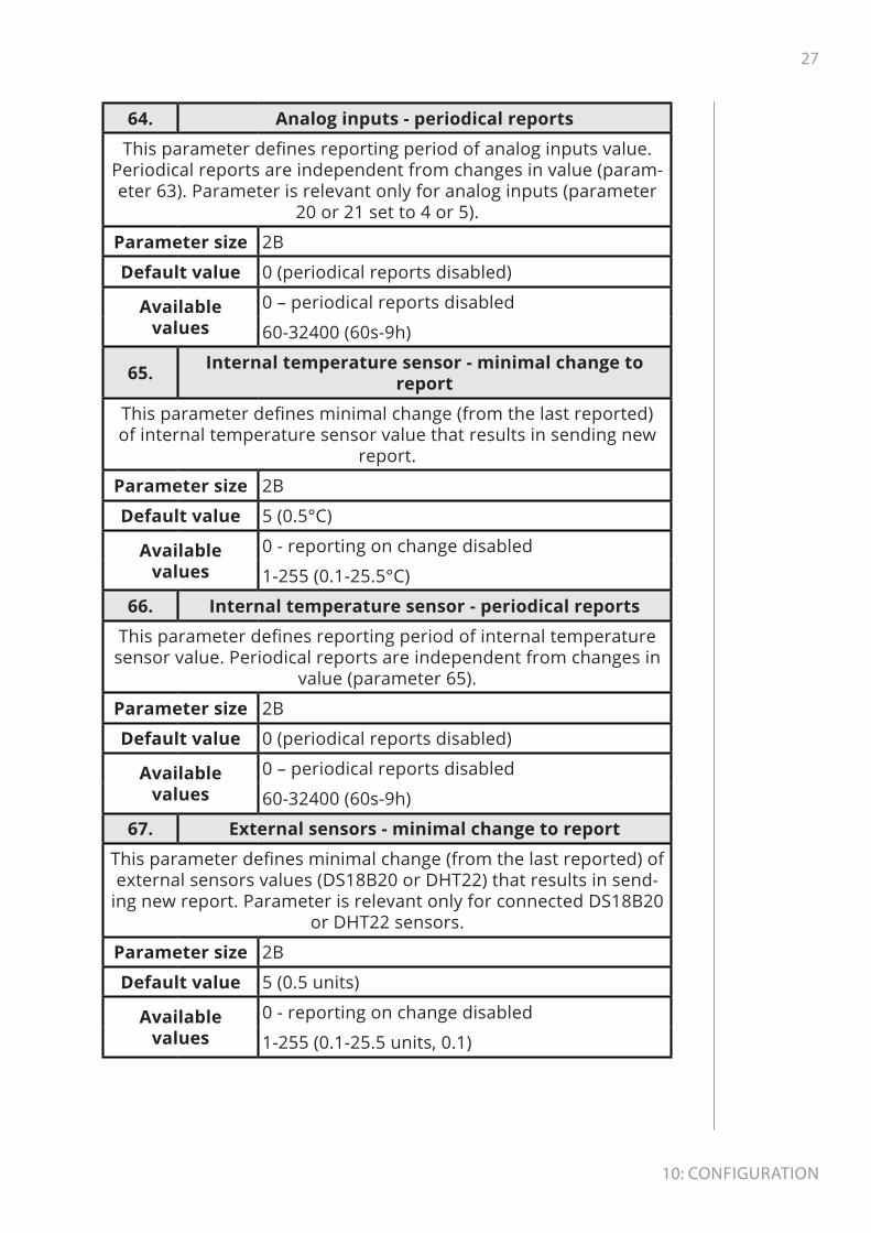
11: Z-WaVe specIfIcatIon
Endpoint 7Generic Device
Class GENERIC_TYPE_SENSOR_MULTILEVEL
Specific Device Class SPECIFIC_TYPE_ROUTING_SENSOR_MULTILEVEL
Command Classes
COMMAND_CLASS_ZWAVEPLUS_INFO [0x5E]COMMAND_CLASS_ASSOCIATION [0x85]
COMMAND_CLASS_MULTI_CHANNEL_ASSOCIA-TION [0x8E]
COMMAND_CLASS_ASSOCIATION_GRP_INFO [0x59]COMMAND_CLASS_NOTIFICATION [0x71]
COMMAND_CLASS_SENSOR_MULTILEVEL [0x31]COMMAND_CLASS_SUPERVISION [0x6C]
COMMAND_CLASS_APPLICATION_STATUS [0x22]COMMAND_CLASS_SECURITY [0x98]
COMMAND_CLASS_SECURITY_2 [0x9F]Description Temperature – internal sensor
Endpoint 8-13 (when DS18S20 sensors connected)Generic Device
Class GENERIC_TYPE_SENSOR_MULTILEVEL
Specific Device Class SPECIFIC_TYPE_ROUTING_SENSOR_MULTILEVEL
Command Classes
COMMAND_CLASS_ZWAVEPLUS_INFO [0x5E]COMMAND_CLASS_ASSOCIATION [0x85]
COMMAND_CLASS_MULTI_CHANNEL_ASSOCIA-TION [0x8E]
COMMAND_CLASS_ASSOCIATION_GRP_INFO [0x59]COMMAND_CLASS_NOTIFICATION [0x71]
COMMAND_CLASS_SENSOR_MULTILEVEL [0x31]COMMAND_CLASS_SUPERVISION [0x6C]
COMMAND_CLASS_APPLICATION_STATUS [0x22]COMMAND_CLASS_SECURITY [0x98]
COMMAND_CLASS_SECURITY_2 [0x9F]Description Temperature – external sensor DS18B20 No 1-6

34
11: Z-WaVe specIfIcatIon
Endpoint 8 (when DHT22 sensor connected)Generic Device
Class GENERIC_TYPE_SENSOR_MULTILEVEL
Specific Device Class SPECIFIC_TYPE_ROUTING_SENSOR_MULTILEVEL
Command Classes
COMMAND_CLASS_ZWAVEPLUS_INFO [0x5E]COMMAND_CLASS_ASSOCIATION [0x85]
COMMAND_CLASS_MULTI_CHANNEL_ASSOCIA-TION [0x8E]
COMMAND_CLASS_ASSOCIATION_GRP_INFO [0x59]COMMAND_CLASS_NOTIFICATION [0x71]
COMMAND_CLASS_SENSOR_MULTILEVEL [0x31]COMMAND_CLASS_SUPERVISION [0x6C]
COMMAND_CLASS_APPLICATION_STATUS [0x22]COMMAND_CLASS_SECURITY [0x98]
COMMAND_CLASS_SECURITY_2 [0x9F]Description Temperature – external sensor DHT22
Endpoint 9 (when DHT22 sensor connected)Generic Device
Class GENERIC_TYPE_SENSOR_MULTILEVEL
Specific Device Class SPECIFIC_TYPE_ROUTING_SENSOR_MULTILEVEL
COMMAND_CLASS_ZWAVEPLUS_INFO [0x5E]COMMAND_CLASS_ASSOCIATION [0x85]
COMMAND_CLASS_MULTI_CHANNEL_ASSOCIA-TION [0x8E]
COMMAND_CLASS_ASSOCIATION_GRP_INFO [0x59]COMMAND_CLASS_NOTIFICATION [0x71]
COMMAND_CLASS_SENSOR_MULTILEVEL [0x31]COMMAND_CLASS_SUPERVISION [0x6C]
COMMAND_CLASS_APPLICATION_STATUS [0x22]COMMAND_CLASS_SECURITY [0x98]
COMMAND_CLASS_SECURITY_2 [0x9F]Description Humidity – external sensor DHT22

35
11: Z-WaVe specIfIcatIon
Notification Command Class: The device uses Notification Command Class to report different events to the controller (“Lifeline” group).
ROOT (Endpoint 1)Notification Type Event
Home Security [0x07] Intrusion Unknown Location [0x02]Endpoint 2
Notification Type EventHome Security [0x07] Intrusion Unknown Location [0x02]
Endpoint 7
Notification Type Event Event /State Parameter
System [0x09]System hardware failure
with manufacturer proprie-tary failure code [0x03]
Device Overheat [0x03]
Endpoint 8-13Notification Type Event
System [0x09] System hardware failure [0x01]
Protection CC:
Protection Command Class allows to prevent local or remote control of the outputs.
Type State Description Hint
Local 0Unprotected - The device is not
protected, and may be operated normally via the user interface.
Inputs connected with outputs.
Local 2No operation possible – state of
output cannot be changed by the B-button or corresponding Input
Inputs discon-nected from
outputs.
RF 0 Unprotected - The device accept and respond to all RF Commands.
Outputs can be controlled via
Z-Wave.
RF 1
No RF control – command class basic and switch binary are reject-
ed, every other command class will be handled
Outputs cannot be controlled via
Z-Wave.

36
11: Z-WaVe specIfIcatIon
Assocation groups mapping:
Root Endpoint Association group in endpoint
Association Group 2 Endpoint 1 Association Group 2
Association Group 3 Endpoint 2 Association Group 2
Basic commands mapping:
Command Root
Endpoints
1-2 3-4 5-6 7-13
Basic Set = EP1Appli-cation
Rejected
Appli-cation
Rejected
Switch Bi-nary Set
Appli-cation
Rejected
Basic Get = EP1 Notifica-tion Get
Sensor Multilevel
Get
Switch Bi-nary Get
Sensor Multilevel
Get
Basic Report = EP1
Notifi-cation Report
Sensor Multilevel
Report
Switch BInary Report
Sensor Multilevel
Report
Other Command Class mappings:
Command Class Root mapped toSensor Multilevel Endpoint 7
Binary Switch Endpoint 5
Protection Endpoint 5

37
12: reGulatIons
12: RegulationsThis device complies with Part 15 of the FCC Rules Operation is subject to the following two conditions:
1. This device may not cause harmful interference
2. This device must accept any interference received, including in-terference that may cause undesired operation. This equipment has been tested and found to comply with the limits for a Class B dig-ital device, pursuant to part 15 of the FCC Rules. These limits are designed to provide reasonable protection against harmful interfer-ence in a residential installation. This equipment generates, uses and can radiate radio frequency energy and, if not installed and used in accordance with the instructions, may cause harmful interference to radio communications. However, there is no guarantee that interfer-ence will not occur in a particular installation. If this equipment does cause harmful interference to radio or television reception, which can be determined by turning the equipment off and on, the user is encouraged to try to correct the interference by one or more of the following measures:
• Reorient or relocate the receiving antenna.
• Increase the separation between the equipment and receiver.
• Connect the equipment into an outlet on a circuit different from that to which the receiver is connected.
• Consult the dealer or an experienced radio/TV technician for help.
Changes and modifications not expressly approved by the manufac-turer or registrant of this equipment can void your authority to op-erate this equipment under Federal Communications Commission’s rules.
Industry Canada (IC) Compliance NoticeThis device complies with Industry Canada license-exempt RSSs. Op-eration is subject to the following two conditions: (1) this device may not cause interference, and (2) this device must accept any interfer-ence, including interference that may cause undesired operation of the device.
Cet appareil est conforme aux normes d’exemption de licence RSS d’Industry Canada. Son fonctionnement est soumis aux deux condi-tions suivantes : (1) cet appareil ne doit pas causer d’interférence et (2) cet appareil doit accepter toute interférence, notamment les in-terférences qui peuvent affecter son fonctionnement.

38
12: reGulatIons
Legal NoticesAll information, including, but not limited to, information regarding the features, functionality, and/or other product specification are subject to change without notice. Fibaro reserves all rights to revise or update its products, software, or documentation without any obli-gation to notify any individual or entity.
FIBARO and Fibar Group logo are trademarks of Fibar Group S.A. All other brands and product names referred to herein are trademarks of their respective holders.
Declaration of conformityHereby, Fibar Group S.A. declares that the device is in com-pliance with the essential requirements and other relevant provisions of Directive 2014/53/EU. The full text of the EU
declaration of conformity is available at the following internet ad-dress: www.manuals.fibaro.com
WEEE Directive ComplianceDevice labelled with this symbol should not be disposed with other household wastes. It shall be handed over to the applica-ble collection point for the recycling of waste electrical and
electronic equipment.