Embed Size (px)
Citation preview
info
@n
ifty
lift
.co
m.c
om
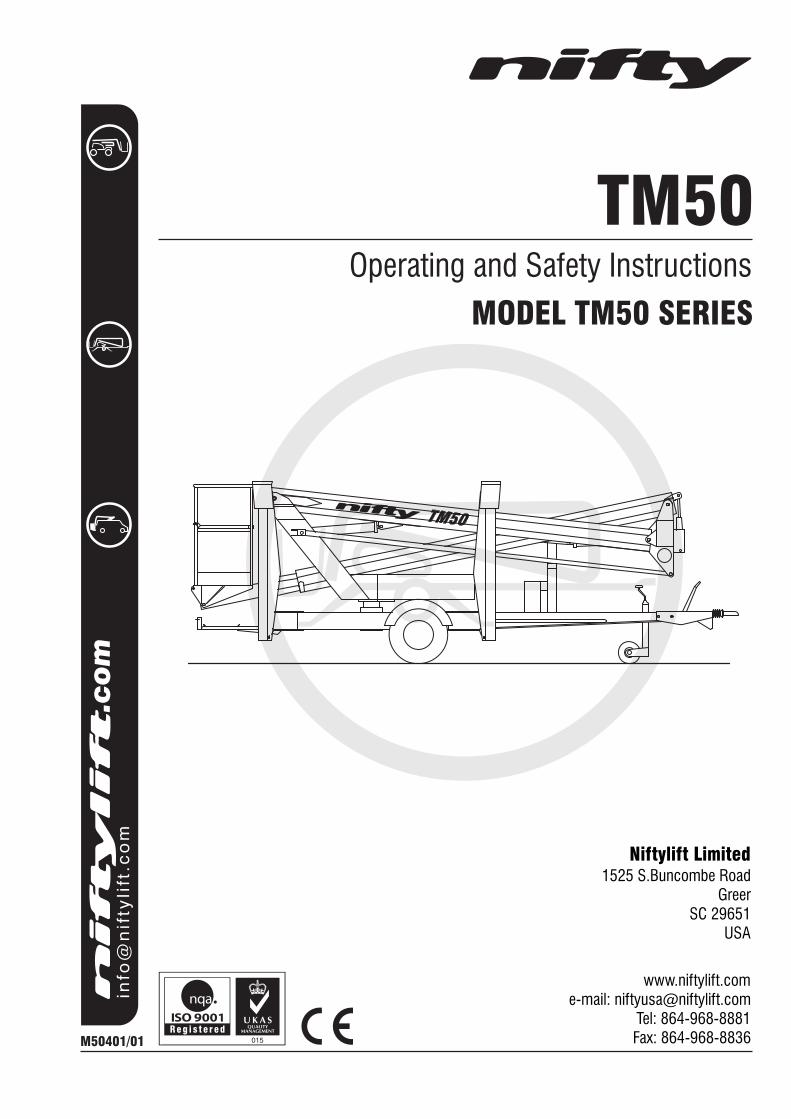
TM50Operating and Safety Instructions
MODEL TM50 SERIES
M50401/01
Niftylift Limited1525 S.Buncombe Road
GreerSC 29651
USA
www.niftylift.come-mail: [email protected]
Tel: 864-968-8881Fax: 864-968-8836
TM50

TM Series Operating & Safety Instructions
English/USA – 01/10 1
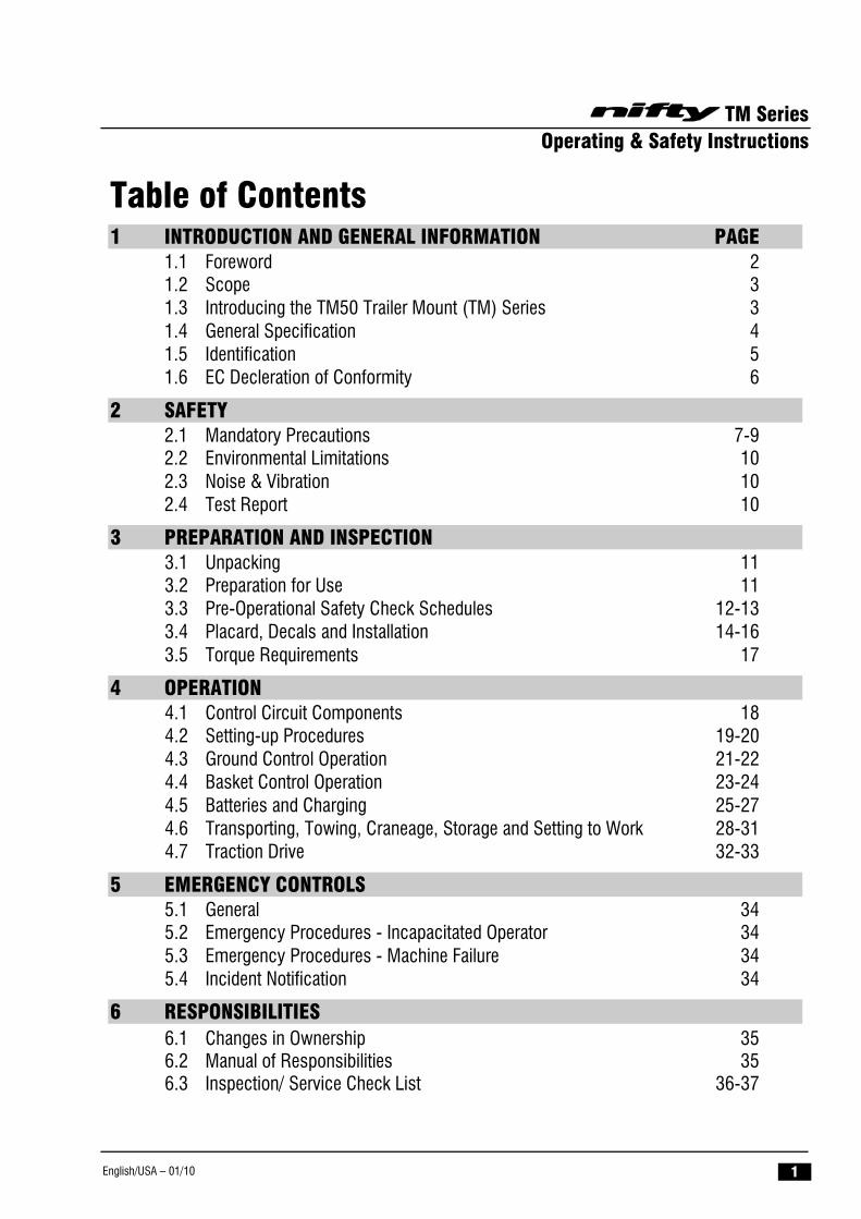
Table of Contents 1 INTRODUCTION AND GENERAL INFORMATION PAGE
1.1 Foreword 2 1.2 Scope 3 1.3 Introducing the TM50 Trailer Mount (TM) Series 3 1.4 General Specification 4 1.5 Identification 5 1.6 EC Decleration of Conformity 6
2 SAFETY 2.1 Mandatory Precautions 7-9 2.2 Environmental Limitations 10 2.3 Noise & Vibration 10 2.4 Test Report 10
3 PREPARATION AND INSPECTION 3.1 Unpacking 11 3.2 Preparation for Use 11 3.3 Pre-Operational Safety Check Schedules 12-13 3.4 Placard, Decals and Installation 14-16 3.5 Torque Requirements 17
4 OPERATION 4.1 Control Circuit Components 18 4.2 Setting-up Procedures 19-20 4.3 Ground Control Operation 21-22 4.4 Basket Control Operation 23-24 4.5 Batteries and Charging 25-27 4.6 Transporting, Towing, Craneage, Storage and Setting to Work 28-31 4.7 Traction Drive 32-33
5 EMERGENCY CONTROLS 5.1 General 34 5.2 Emergency Procedures - Incapacitated Operator 34 5.3 Emergency Procedures - Machine Failure 34 5.4 Incident Notification 34
6 RESPONSIBILITIES 6.1 Changes in Ownership 35 6.2 Manual of Responsibilities 35 6.3 Inspection/ Service Check List 36-37
TM Series Operating & Safety Instructions
English/USA – 01/10 2
1 Introduction and General Information 1.1 FOREWORD
The purpose of these manuals is to provide the customer with appropriate safety operating and maintenance instructions essential for proper machine operation.
All information in these manuals should be READ and fully UNDERSTOOD before any attempt is made to operate the machine. THESE MANUALS ARE VERY IMPORTANT TOOLS - Keep them with the machine at all times.
The manufacturer has no direct control over machine application and use, therefore conformance with good safety practices is the responsibility of the user and his operating personnel.
All information in these manuals is based on the use of the machine under proper operating conditions. Alteration and/or modification of the machine are strictly forbidden.
One of the most important facts to remember is that any equipment is only as safe as those who operate it.
DANGER, WARNING, CAUTION, IMPORTANT, INSTRUCTIONS AND NOTICE
Any place these topics may appear, either in this manual or on the machine, they are defined as follows:
DANGER: If not correctly followed there is a high probability of serious injury or death to personnel.
WARNING OR CAUTION: If not correctly followed there is some possibility of serious injury or death to personnel.
THE 'SAFETY ALERT' SYMBOL IS USED TO CALL ATTENTION TO POTENTIAL HAZARDS THAT MAY LEAD TO SERIOUS INJURY OR DEATH, IF IGNORED.
IMPORTANT AND INSTRUCTIONS: Denotes procedures essential to safe operation and prevention of damage to or destruction of the machine.
NOTICE: Indicates general safety rules and/or procedures relating to the machine.
It is the owner's/user's responsibility to know and comply with all applicable rules, regulations, laws, codes and any other requirements applicable to the safe use of this equipment.
TM Series Operating & Safety Instructions
English/USA – 01/10 3
1.2 SCOPE These operating instructions contain all the necessary information required to allow the safe operation of any Niftylift TM50, powered by electric (DC), diesel (D), gasoline (P) engine, or a combination of these.
For further technical information, circuit diagrams and specific instructions for all maintenance which may need to be carried out by specialist trained personnel, see the associated Workshop and Parts manual for your model of Niftylift TM50.
1.3 INTRODUCING THE TM50 TRAILER MOUNT (TM) SERIES Please note at the time of going to press all information, illustrations, details and descriptions contained herein are valid. Niftylift reserves the right to change, alter, modify or improve its products without any obligations to install them on previously manufactured machines.
If you require further information after reading this manual please do not hesitate to contact us at your nearest office.
Niftylift Inc, 1525 S. Buncombe Road, Greer, SC 29651 USA
Tel: 864 968 8881 Fax: 864 968 8836 Email: [email protected]
The Niftylift TM50 trailer mount is an extremely versatile articulated boom platform of unique and simple design. It is capable of placing two men and their tools up to a height of 56ft or an outreach of 28ft 5in.
The booms are mounted via a 360o powered swing mechanism on to a compact base balanced on a single axle. The fully articulating booms give an outstanding working envelope. The large pneumatic wheels and minimal weight make the unit light and simple to manoeuvre.
A simple, all-hydraulic proportional control system gives smooth, reliable movement of the platform and maximum reliability in the harshest environments.
The Niftylift TM50 is available with manual or hydraulically powered outriggers , either option making setting up both swift and simple. A unique pressure sensitive microswitch system fitted to each outrigger prevents operation of the machine until all outriggers have been correctly deployed and also provides a loud audible alarm warning of a possibly hazardous situation. This Operating Manual provides instructions for both manual and hydraulic outrigger options. Models include the following:
E: - DC ELECTRIC DE: - BI-ENERGY (DIESEL & BATTERY) AC: - AC ELECTRIC GE: - GASOLINE & BATTERY D: - DIESEL GG: - GASOLINE & LPG (PROPANE) G: - GASOLINE T: - TRI - ENERGY (GASOLINE, PROPANE & BATTERY) A: - AIR
TM Series Operating & Safety Instructions
English/USA – 01/10 4
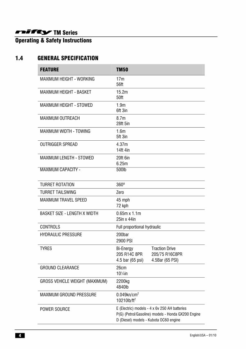
1.4 GENERAL SPECIFICATION
FEATURE TM50
MAXIMUM HEIGHT - WORKING 17m 56ft
MAXIMUM HEIGHT - BASKET 15.2m 50ft
MAXIMUM HEIGHT - STOWED 1.9m 6ft 3in
MAXIMUM OUTREACH 8.7m 28ft 5in
MAXIMUM WIDTH - TOWING 1.6m 5ft 3in
OUTRIGGER SPREAD 4.37m 14ft 4in
MAXIMUM LENGTH - STOWED 20ft 6in 6.25m
MAXIMUM CAPACITY - 500lb
TURRET ROTATION 360º
TURRET TAILSWING Zero
MAXIMUM TRAVEL SPEED 45 mph 72 kph
BASKET SIZE - LENGTH X WIDTH 0.65m x 1.1m 25in x 44in
CONTROLS Full proportional hydraulic
HYDRAULIC PRESSURE 200bar 2900 PSI
TYRES Bi-Energy Traction Drive 205 R14C 8PR 205/75 R16C8PR 4.5 bar (65 psi) 4.5Bar (65 PSI)
GROUND CLEARANCE 26cm 10¼in
GROSS VEHICLE WEIGHT (MAXIMUM) 2200kg 4840lb
MAXIMUM GROUND PRESSURE 0.049kn/cm2 10210lb/ft2
POWER SOURCE E (Electric) models - 4 x 6v 250 AH batteries P(G) (Petrol/Gasoline) models - Honda GX200 Engine D (Diesel) models - Kubota OC60 engine
TM Series Operating & Safety Instructions
English/USA – 01/10 5
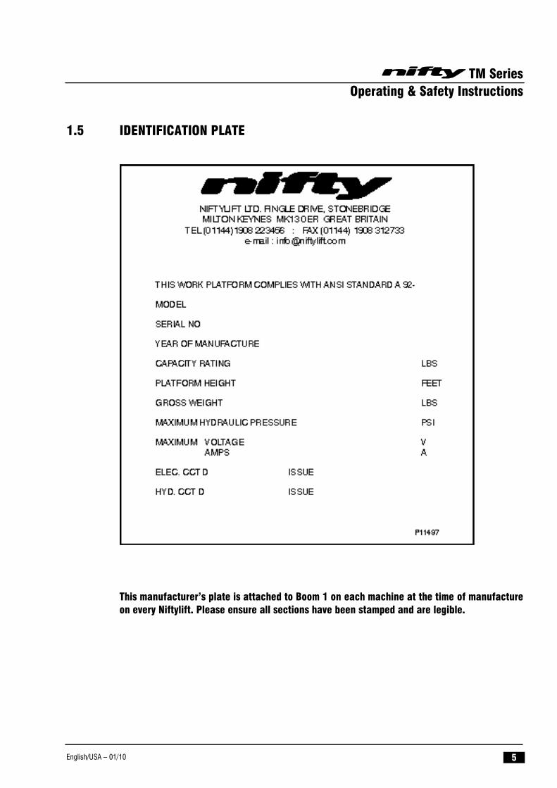
1.5 IDENTIFICATION PLATE
This manufacturer’s plate is attached to Boom 1 on each machine at the time of manufacture on every Niftylift. Please ensure all sections have been stamped and are legible.
TM Series Operating & Safety Instructions
English/USA – 01/10 6
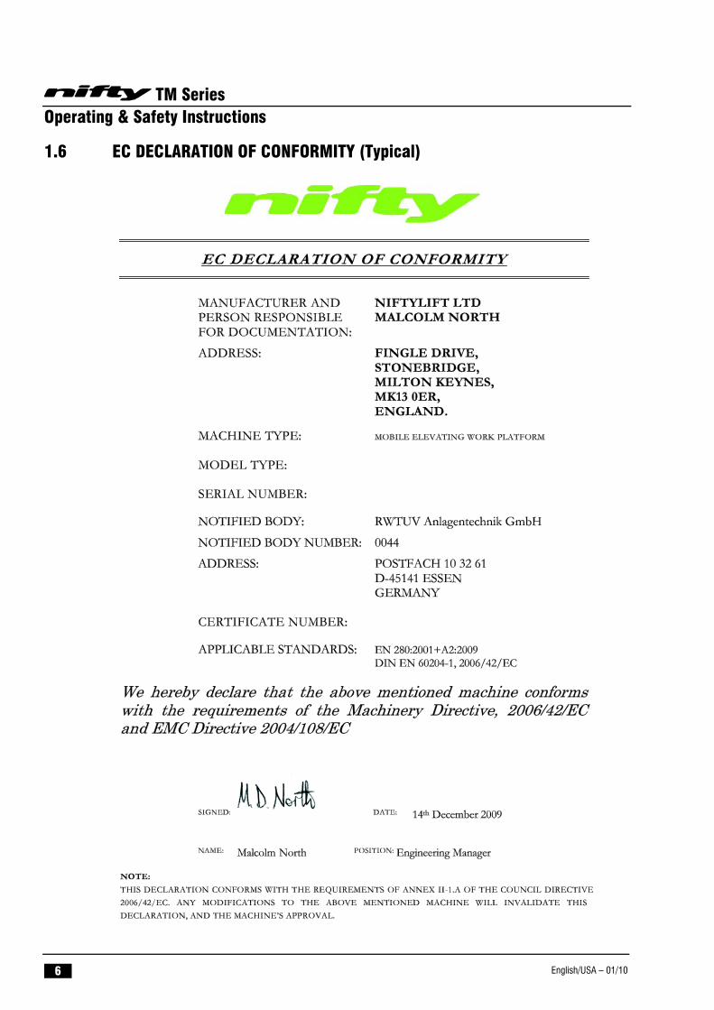
1.6 EC DECLARATION OF CONFORMITY (Typical)
TM Series Operating & Safety Instructions
English/USA – 01/10 7
2 Safety 2.1 MANDATORY PRECAUTIONS
When operating your Niftylift, your safety is of utmost concern. In order to fully appreciate all aspects of the machines operation it should be ensured that each operator has READ and fully UNDERSTOOD the relevant manual covering machine use, maintenance and servicing. If any doubts exist concerning any points covered in your manual, contact your local dealer or Niftylift Ltd.
Before using any Niftylift, thoroughly inspect the machine for damage or deformation to all major components. Likewise, check the control systems for hydraulic leaks, damaged hoses, cable faults or loose covers to electrical components. At no time should damaged or faulty equipment be used - Correct all defects before putting the platform to work. If in doubt, contact your local dealer or Niftylift Ltd (see front cover for address).
THE MANUFACTURER HAS NO DIRECT CONTROL OVER THE MACHINE APPLICATION AND USE. THEREFORE CONFORMATION WITH GOOD SAFETY PRACTICES IS THE RESPONSIBILITY OF THE USER AND HIS OPERATING PERSONNEL. FAILURE TO UNDERSTAND AND FOLLOW ALL SAFETY RULES COULD RESULT IN SERIOUS INJURY OR DEATH.
2.1.1 Only trained persons will be permitted to operate the Niftylift.
2.1.2 Always operate the Niftylift in full accordance with the manufacturers Operating & Safety Instructions for that model.
2.1.3 Before use each day and at the beginning of each shift the Niftylift shall be given a visual inspection and functional test including, but not limited to, operating and emergency controls, safety devices, personal protective clothing, including fall protection, air, hydraulic and fuel system leaks, cables and wiring harness, loose or missing parts, tyres and wheels, placards, warnings, control markings and Operating and Safety Manuals, guards and guard rail systems and all other items specified by the manufacturer.
2.1.4 Any problems or malfunctions that affect operational safety must be repaired prior to use of the platform, with specific regard to any safety components refer to the Parts Manual for part numbers and details. If in doubt, contact Niftylift Ltd (Details on page 3).
2.1.5 Always ensure that all warning labels, instructions, placards, control markings and Safety Manuals are intact and clearly legible. If replacements are required contact your local dealer or Niftylift. Always observe and obey safety and operating instructions on such labels.
2.1.6 Do not alter, modify or disable in any way the controls, safety devices, interlocks or any other part of the machine.
2.1.7 Before the Niftylift is used and during use the user shall check the area in which it is to be used for possible hazards such as, but not limited to, uneven ground drop-offs, holes, bumps, obstructions, debris, floor and overhead obstructions, high voltage conductors, wind and weather, unauthorised persons and any other possibly hazardous conditions.
2.1.8 Never exceed the maximum platform capacity, as indicated on the decals and machine serial plate.
TM Series Operating & Safety Instructions
English/USA – 01/10 8
2.1.9 Never position any part of the Niftylift within 12ft of any electrical power line, conductor or similar not exceeding 66kV. (Minimum span 125m) Other distances for increased voltages and different spans are given in NZECP 34:1993
THIS MACHINE IS NOT INSULATED.
If in doubt, contact the appropriate authorities.
2.1.10 On entering the basket ensure that the drop down entry bar is closed afterwards.
2.1.11 Use of an approved safety belt and lanyard, hardhat and appropriate safety clothing is mandatory. Fasten harness to designated harness securing points within the platform and do not remove until leaving the platform whilst in the stowed position.
2.1.12 Always remain standing within the basket. Do not attempt to increase your height or reach by standing and/or climbing on the basket guardrails or any other object. KEEP YOUR FEET ON THE BASKET FLOOR. Do not sit, stand or climb on the guardrail, mid rail or boom linkage. Use of planks, ladders or any other devices on the Niftylift for achieving additional height or reach shall be prohibited.
2.1.13 Do not use the basket levelling system to artificially increase the outreach of the platform. Never use boards or ladders in the basket to achieve the same result.
2.1.14 Do not use the basket to lift overhanging or bulky items that may exceed the maximum capacity or carry objects that may increase the wind loading on the platform. (E.g. Notice boards etc.)
2.1.15 The Niftylift shall not be operated from a position on trucks, trailers, railway cars, floating vessels, scaffolds or similar equipment unless Niftylift Ltd in Great Britain approves the application in writing.
2.1.16 Always check below and around the platform before lowering or rotating the booms to ensure that the area is clear of personnel and obstructions. Care should be taken when rotating the booms out into areas where there may be passing traffic. Use barriers to control traffic flow or prevent access to the machine.
2.1.17 Stunt driving and horseplay, on or around the Niftylift, shall not be permitted.
2.1.18 When other moving equipment and vehicles are present, special precautions shall be taken to comply with local ordinances or safety standards established for the work place. Warnings such as, but not limited to, flags, roped off areas, flashing lights and barricades shall be used.
2.1.19 It shall be the responsibility of the user to determine the hazard classification of any particular atmosphere or location. Aerial platforms operated in hazardous locations shall be approved and of the type required. (For the USA refer to ANSI/NFPA 505-1987.)
2.1.20 The operator shall immediately report to his supervisor any potentially hazardous location(s) (environment) which become evident during operation.
2.1.21 If an operator encounters any suspected malfunction of the Niftylift or any hazard or potentially unsafe condition relating to capacity, intended use or safe operation he shall cease operation of the Niftylift and request further information as to safe operation from his management, or owner, dealer or manufacturer before further operation of the Niftylift.

TM Series Operating & Safety Instructions
English/USA – 01/10 9
TM Series Operating & Safety Instructions
English/USA – 01/10 10
2.1.22 The operator shall immediately report to his superior any problems or malfunctions of the Niftylift, which becomes evident during operation. Any problems or malfunctions that affect the safety of operation shall be repaired prior to continued use.
2.1.23 The boom and platform of the Niftylift shall not be used to jack the wheels off the ground.
2.1.24 The Niftylift shall not be used as a crane.
2.1.25 The Niftylift shall not be positioned against another object to steady the platform.
2.1.26 Care should be taken to prevent rope, electric cords and hoses from becoming entangled in the aerial platform.
2.1.27 Batteries shall be recharged in a well-ventilated area free of flame, sparks or other hazards that may cause explosion. Highly explosive hydrogen gas is produced during the charging process.
2.1.28 When checking electrolyte levels great care should be taken to protect eyes, skin and clothing. Battery acid is highly corrosive and protective glasses and clothing is recommended.
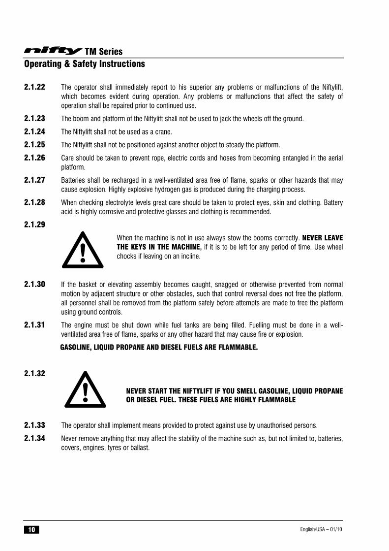
2.1.29
When the machine is not in use always stow the booms correctly. NEVER LEAVE THE KEYS IN THE MACHINE, if it is to be left for any period of time. Use wheel chocks if leaving on an incline.
2.1.30 If the basket or elevating assembly becomes caught, snagged or otherwise prevented from normal motion by adjacent structure or other obstacles, such that control reversal does not free the platform, all personnel shall be removed from the platform safely before attempts are made to free the platform using ground controls.
2.1.31 The engine must be shut down while fuel tanks are being filled. Fuelling must be done in a well-ventilated area free of flame, sparks or any other hazard that may cause fire or explosion.
GASOLINE, LIQUID PROPANE AND DIESEL FUELS ARE FLAMMABLE.
2.1.32
NEVER START THE NIFTYLIFT IF YOU SMELL GASOLINE, LIQUID PROPANE OR DIESEL FUEL. THESE FUELS ARE HIGHLY FLAMMABLE
2.1.33 The operator shall implement means provided to protect against use by unauthorised persons.
2.1.34 Never remove anything that may affect the stability of the machine such as, but not limited to, batteries, covers, engines, tyres or ballast.
TM Series Operating & Safety Instructions
English/USA – 01/10 11
2.2 ENVIRONMENTAL LIMITATIONS
All Niftylift Trailer Mounts are limited to operation as previously described and any slopes must be adjusted by use of the outriggers and jacks. Unless specifically configured otherwise, the machine will have short time rating for operation in extreme temperatures, i.e. reduced battery cycle times for low temperatures such as freezers, food storage etc. and cooling limitations for high temperatures as oil temperature must remain between -23° and 93° Celsius.
Extended operation in dusty environments is not recommended and frequent cleaning will be necessary. All dust, dirt, salt encrustation, excess oil or grease should be removed. Deposits of paint or bitumen, particularly on legends or labels should also be removed.
All standard Niftylift machines are rated for a wind speed of 12.5 m/s, which equates to 28mph or force 6 on the Beaufort scale. No attempt should be made to operate a Niftylift in wind strengths above this limit and if the operator has any doubts over the wind speed he / she should cease operation immediately until it can be established that the wind speed has fallen to a safe level.
DO NOT USE THE NIFTYLIFT IN ELECTRICAL STORMS
2.3 NOISE AND VIBRATION
The airborne noise emission on the 170 range of machines does not exceed 73dB(A), measured at a perpendicular distance of 4m, under equivalent continuous A-weighted sound pressure test conditions. This was based on a Diesel powered machine, working under load. All other models will exhibit significantly lower emissions than this figure, dependant on power option.
In normal operation the Vibration level to which the operator is subjected will not exceed a weighted root mean square acceleration value of 2.5 m/s2.
2.4 TEST REPORT All Niftylift machine models are subjected to a comprehensive ‘type test’ which duplicates all combinations of safe working load (SWL), overload, windage, inertia and pull force to assess the various safe stability criteria. Self propelled machines are also subjected to kerb and braking tests at the SWL to satisfy additional ‘worse case’ stability requirements.
Each individual machine is then subjected to static overload tests on flat level ground with 150% of the SWL, exceeding the requirements of EN280 for power operated MEWPs. Self propelled machines are also tested at the maximum working angle plus 0.5º with a test load of 125% of the SWL. Finally, on all machines, a functional test is performed with 110% of SWL.
All safety devices are checked for correct operation, operating speeds are checked against benchmark figures and the dynamic functions ensure that all acceleration and deceleration forces are within acceptable limits. All noted defects are rectified and recorded before the machine is permitted to enter into service.
TM Series Operating & Safety Instructions
English/USA – 01/10 12
3 Preparation and Inspection 3.1 UNPACKING
Since the manufacturer has no direct control over the shipping or carriage of any Niftylift it is the responsibility of the dealer and/or owner and/or leaser to ensure the Niftylift has not been damaged in transit and a Pre-operational Report has been carried out by a qualified engineer before the aerial platform is put into service.
A) Remove all ropes, straps and or chains used to secure the aerial platform during transit.
B) Ensure any ramp, loading dock or forklift used is capable of supporting or lifting the aerial platform.
***Carry out the Pre-operational Report before placing machine in service.
3.2 PREPARATION FOR USE Whilst every effort has been made at the Niftylift factory to ensure your machine arrives in a safe and operable condition it is necessary to carry out a systematic inspection prior to putting the aerial platform into service.
THIS IS NOT A REQUEST IT IS MANDATORY
To assist the user in this task you will find enclosed an Inspection Check List (see section 6.3), which must be filled out upon delivery/receipt of the machine.
Before the user carries out the Inspection Check List he must have read and fully understood all the contents of the Operating, Safety and Maintenance Manual.
WARNING - DO NOT OPERATE A POTENTIALLY DEFECTIVE OR MALFUNCTIONING MACHINE. CORRECT AND REPAIR ANY DEFECTS BEFORE OPERATING YOUR NIFTYLIFT.
TM Series Operating & Safety Instructions
English/USA – 01/10 13
3.3 PRE-OPERATIONAL SAFETY CHECK SCHEDULES Before use at the beginning of the work shift, the aerial platform shall be given a visual inspection and functional tests including, but not limited to the following. It is recommended that these be performed at regular intervals as indicated on each checklist.
3.3.1 DAILY SAFETY CHECKS
1) Check that all labels (decals) are in place and legible.
2) Visually inspect the machine for damaged or loose components.
3) Check that batteries are charged
4) Check the fuel level (if applicable).
5) Check that canopies/covers and guards are in place and secure.
6) Check that the boom rest switch is operable (if applicable).
7) Check that control levers are secure and operate freely.
8) Check that operating buttons and emergency stop buttons function properly.
9) Check the operation of the manual hand pump.
10) Visually inspect all hydraulic hoses and fittings for damage or leaks.
11) Check operation of the outrigger alarm.
12) Check that outrigger footpads are secure.
13) Check that the platform pivot pins and their tag bolts are secure.
14) Check security and operation of the boom clamp.
15) Check the operation of the cage weigh system (If fitted).
16)
3.3.2 WEEKLY SAFETY CHECKS
1) Inspect tyres and wheels for damage and wear.
2) Check tyres for correct pressure. 65psi (4.5 bar)
3) Check mudguards for security and damage.
4) Check battery fluid levels and specific gravity (after charging) and general condition.
5) Check hydraulic oil level, ISO Grade 22 (Europe), Grade 32 (Rest of World).
6) Inspect the engine air filter and clean or replace if necessary.
7) Check that the tow hitch ball lock, breakaway cable/chain and jacking wheel are secure.
8) Check operation and security of outrigger micro switches in conjunction with the alarm system. 9) Inspect hose track for damage or missing parts.
TM Series Operating & Safety Instructions
English/USA – 01/10 14
3.3.3 MONTHLY SAFETY CHECKS
1) Check the engine oil level (if applicable).
2) Check the wheel nuts (torque 110ft lbs/150Nm or 117ft lbs/160Nm Traction Drive Option).
3) Check outriggers for condition, security and operation.
4) Check that the rotation gear worm is secure and correctly in mesh. Clean and re-grease.
5) Inspect brakes for operation and wear.
6) Grease the knuckle and centre post.
7) Inspect the engine fuel tank for damage or leaks.
8) Check telescopic boom wear pads and nylon studs (if applicable).
9) Grease the tow hitch assembly.
10) Lightly oil the jack pad ball joints and outrigger housings.
11) Lightly oil the locating pins on outriggers (170M only).
12) Oil and check the operation of manual jacks.
13) Check and adjust if necessary the Nylatron studs around the telescope boom.
14) Every three months check and verify the calibration of the cage weigh system. See section 4.5.4 for the calibration procedure.
15)
3.3.4 ANNUAL SAFETY CHECKS 1) Check that all pivot pins and their tag bolts are secure.
2) Inspect for any cracks or badly rusted areas on booms and chassis.
3) Change the hydraulic oil and the oil filters.
4) Inspect the suspension on each axle unit.
5) Check that rotation gear ring bolts are secure (torque 155ft lbs. 210Nm).
6) Inspect the wear of jack threads (manual jacks).
TM Series Operating & Safety Instructions
English/USA – 01/10 15
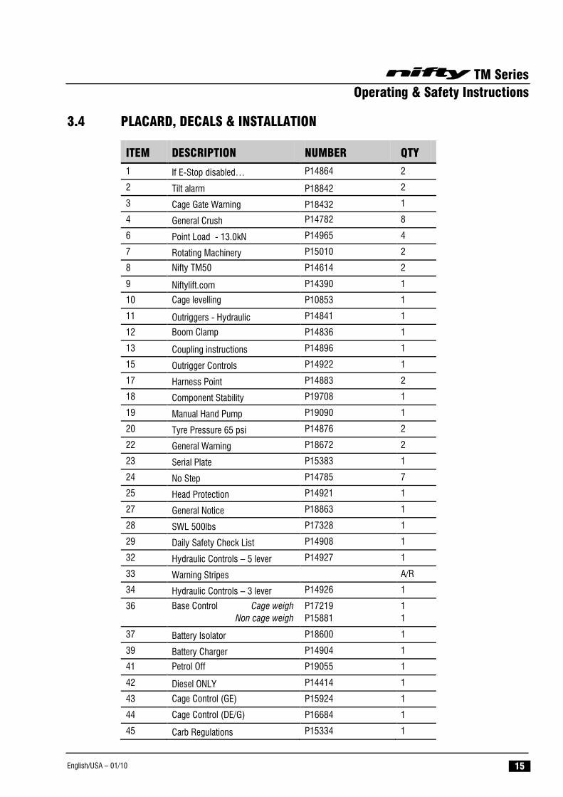
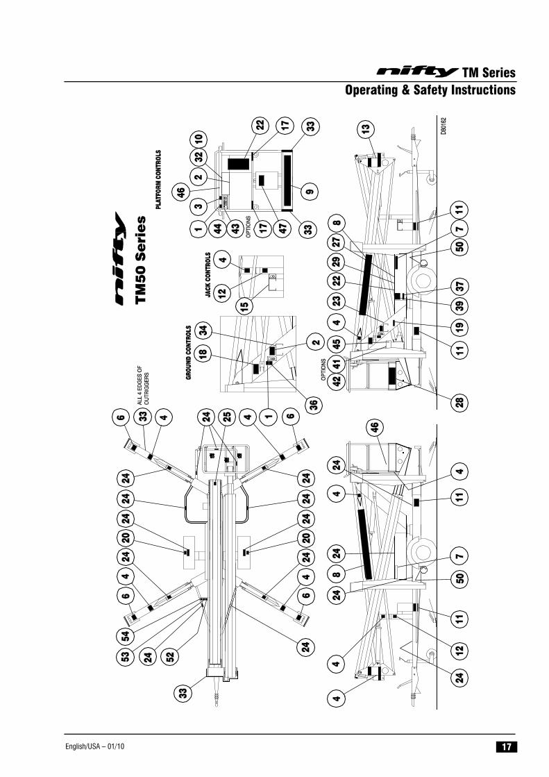
3.4 PLACARD, DECALS & INSTALLATION
ITEM DESCRIPTION NUMBER QTY
1 If E-Stop disabled… P14864 2
2 Tilt alarm P18842 2
3 Cage Gate Warning P18432 1
4 General Crush P14782 8
6 Point Load - 13.0kN P14965 4
7 Rotating Machinery P15010 2
8 Nifty TM50 P14614 2
9 Niftylift.com P14390 1
10 Cage levelling P10853 1
11 Outriggers - Hydraulic P14841 1
12 Boom Clamp P14836 1
13 Coupling instructions P14896 1
15 Outrigger Controls P14922 1
17 Harness Point P14883 2
18 Component Stability P19708 1
19 Manual Hand Pump P19090 1
20 Tyre Pressure 65 psi P14876 2
22 General Warning P18672 2
23 Serial Plate P15383 1
24 No Step P14785 7
25 Head Protection P14921 1
27 General Notice P18863 1
28 SWL 500lbs P17328 1
29 Daily Safety Check List P14908 1
32 Hydraulic Controls – 5 lever P14927 1
33 Warning Stripes A/R
34 Hydraulic Controls – 3 lever P14926 1
36 Base Control Cage weigh Non cage weigh
P17219 P15881
1 1
37 Battery Isolator P18600 1
39 Battery Charger P14904 1
41 Petrol Off P19055 1
42 Diesel ONLY P14414 1
43 Cage Control (GE) P15924 1
44 Cage Control (DE/G) P16684 1
45 Carb Regulations P15334 1
TM Series Operating & Safety Instructions
English/USA – 01/10 16
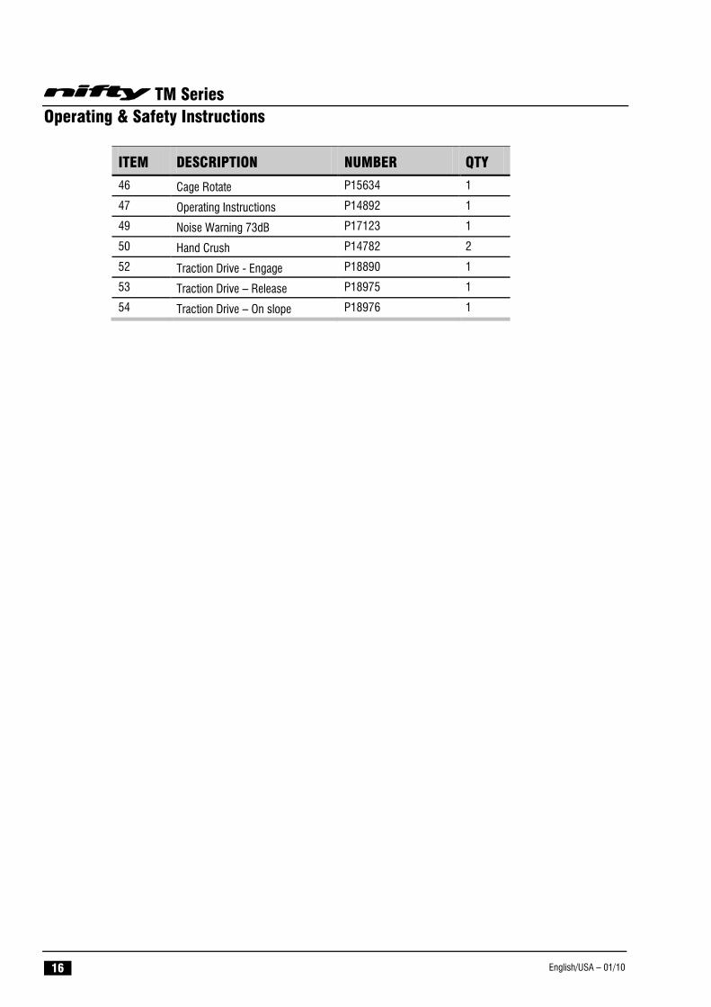
ITEM DESCRIPTION NUMBER QTY
46 Cage Rotate P15634 1
47 Operating Instructions P14892 1
49 Noise Warning 73dB P17123 1
50 Hand Crush P14782 2
52 Traction Drive - Engage P18890 1
53 Traction Drive – Release P18975 1
54 Traction Drive – On slope P18976 1
TM Series Operating & Safety Instructions
English/USA – 01/10 17
TM Series Operating & Safety Instructions
English/USA – 01/10 18
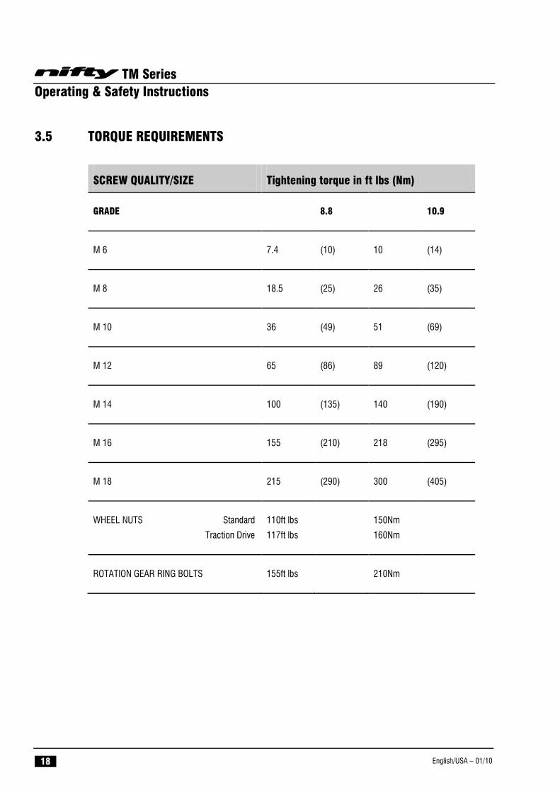
3.5 TORQUE REQUIREMENTS
SCREW QUALITY/SIZE Tightening torque in ft lbs (Nm)
GRADE 8.8 10.9
M 6 7.4 (10) 10 (14)
M 8 18.5 (25) 26 (35)
M 10 36 (49) 51 (69)
M 12 65 (86) 89 (120)
M 14 100 (135) 140 (190)
M 16 155 (210) 218 (295)
M 18 215 (290) 300 (405)
WHEEL NUTS Standard
Traction Drive
110ft lbs
117ft lbs
150Nm
160Nm
ROTATION GEAR RING BOLTS 155ft lbs 210Nm
TM Series Operating & Safety Instructions
English/USA – 01/10 19
4 Operation 4.1 CONTROL CIRCUIT COMPONENTS
4.1.1 CONTROL BOARD: - Situated under the canopy, the control board comprises a PCB (printed circuit board) design that incorporates all of the relays to control the machine operation. The control board is common between models with the same power source, and will contain, where appropriate, discrete fuses for the circuits concerned.
4.1.2 KLAXON: - Also mounted under the canopy is a klaxon, which is interlocked into the stabiliser control circuit. It is this device that sounds continuously if an outrigger goes light in operation, with the booms raised, warning the operator of this condition. It will also sound if the Ground Control Key switch is turned to Platform position before the outriggers are deployed.
4.1.3 BOOM-SWITCH (TM50 ONLY): - Mounted on the underside of the boom rest and operated by contact with boom 3, this switch controls the changeover function between outriggers and basket. The outrigger control function is not available unless this switch is engaged with the boom, ensuring that the machine must be stowed to operate the hydraulic jacks. It is also similarly linked into the platform control circuit, such that if the switch is not engaged with the booms, (i.e. machine is in operation) then the outrigger sensors are active and would warn the operator of an unsafe condition, should one of them loose contact with the ground. These control functions are of primary importance to safety of the machine and operator. Under no circumstances should this control function be isolated or by-passed.
4.1.4 BATTERY ISOLATOR: - A battery isolator handle is located beneath the canopy which allows the machine control and power circuits to be isolated from the batteries themselves. Under normal operation, the machine Key switch should be used to isolate the machine with the Battery Isolator only being required to disconnect the batteries for maintenance or in the event of a short circuit. The battery charging circuit is connected directly to the battery side, so charging is un-affected by use of this switch.
4.1.5 POWER SOURCE SELECTION (TM50H ONLY):- On multiple power option machines, the machine is fitted with an ‘instinctive’ circuit for power source selection. Pressing the green button will automatically select battery operation. The engine can be started using the two position START/STOP selector in the basket and the machine will ‘default’ to engine operation via a flow switch in the hydraulic circuit. Stopping the engine by selecting STOP on the two position selector in the basket and pressing the green button will return the machine to battery mode.
4.1.6 DIESEL ENGINE: - Generally a Yanmar L40 or Kubota 0C60 engine, described in the maintenance section of the Workshop Manual, driving a single bodied pump with direct mounted pump dump valve.
4.1.7 GASOLINE ENGINE: - Generally a Honda GX 160 engine, described in the maintenance section of the Workshop Manual, driving a single body pump with direct mounted pump dump valve.
TM Series Operating & Safety Instructions
English/USA – 01/10 20
4.2 SETTING UP PROCEDURES
FAILURE TO DEPLOY THE OUTRIGGERS CORRECTLY COULD RESULT IN DEATH OR SERIOUS INJURY.
ALL MODELS
1) Read and fully comply with all safety precautions and operating instructions in the Operating and Safety manual and the warning decals on the machine.
2) Position Niftylift on firm ground, bearing in mind range of boom movement so that any overhead obstructions or possible hazards such as, but not limited to, power cables, telephone lines, drains, manhole covers, etc. can be safely avoided
3) APPLY HANDBRAKE: Chock wheels and cordon off the area using appropriate cones, barriers and flags.
4) Levelling the machine using the outriggers can accommodate a slope of up to 12 degrees, if necessary using suitable load bearing pads to support the downhill outriggers. Do not elevate the basket unless the base can be corrected to within one degree of level.
5) If the load bearing capacity of the ground is in any doubt the machine must NOT be used.
6) Release boom travelling clamp.
7) Check all red emergency stops are not engaged (i.e. fully out).
8) Follow instructions below for either manual or hydraulic outrigger models
MANUAL OUTRIGGER (TM50M) MODELS
9) Leave ground control key in centre “OFF” position until outriggers are deployed. Turning this key to basket position will cause the Klaxon to sound, as the outriggers will detect that the jacks are not in contact with the ground.
10) All four outrigger beams must be fully extended with all of the retaining pins engaged (i.e. dropped) and all jack feet screwed down hard onto a firm, surface.
11) Check that the base is level using the spirit level adjacent to boom clamp post.
12) To operate the booms from the ground turn the key switch selector at the ground control station to “Ground”, (i.e. anti-clockwise). Depress and hold green power button and select appropriate control lever. Note: If no power is available check that each retaining pin has engaged and that each jack foot is in contact with the ground and taking equal weight.
13) To operate the booms from the basket turn the key switch selector at the ground control station to “platform” (i.e. clockwise). Note: If alarm sounds return key to centre “OFF” position and check that each retaining pin has engaged and that each jack foot is in contact with the ground and taking equal weight.
TM Series Operating & Safety Instructions
English/USA – 01/10 21
HYDRAULIC OUTRIGGERS (TM50H) MODELS
9) Ensure that the key switch at the ground control station is turned to the “ON” position (i.e. clockwise).
10) At the outrigger control station press down and hold the power lever on the right hand side. This activates the power and diverts hydraulic flow to the outriggers for setting up. Then select the appropriate control lever to begin set up. Note: No power will be available if the booms are not stowed onto the boom rest.
11) Using the four outrigger control levers, lower each outrigger onto a firm, surface and level the machine base ensuring each outrigger foot is taking equal weight with the wheels clear of the ground. Note: Deploy the front two outriggers first to minimise the risk of damaging the jacking wheel.
12) Check that the base is level using the spirit level adjacent to outrigger control station.
13) The booms can now be operated from the ground control station by pressing and holding the green power button. Note: If no power is available check that each outrigger is lowered and each footpad is taking equal weight.
14) To operate the booms from the basket, remove the key from the ground control station (turn key anti-clockwise) and put the key in the basket control station and switch to “ON” (clockwise). Note: If the klaxon alarm sounds check that each outrigger is lowered and each footpad is taking equal weight.
ALL MODELS
15) Always lower booms fully before adjusting, raising, retracting or moving the outriggers in any way.
16) Never alter, modify or block any of the safety circuits on the Niftylift.
THIS MACHINE IS NOT ELECTRICALLY INSULATED. DO NOT WORK WITHIN 10FT OF OVERHEAD CABLES EXCEEDING 415 VOLTS
TM Series Operating & Safety Instructions
English/USA – 01/10 22
4.3 GROUND CONTROL OPERATION
ALWAYS ALLOW THE ENGINE TO WARM UP BEFORE OPERATING.
4.3.1 GROUND CONTROL INSTRUCTIONS
ALL MODELS
1) Check below, above and around the platform for any obstructions or hazards before operating any function.
2) Ensure all red emergency stops are out.
3) For the hydraulic outrigger model (TM50H), turn the key switch at the ground control station to the “ON” position (i.e. clockwise). For manual outrigger model (TM50M) turn the key switch at the ground control station to “Ground” (i.e. anti-clockwise)
4) Battery/Electric models go to step 11).
DIESEL ENGINE OR BI-ENERGY MODELS
5) Turn the main engine ignition switch, located on the side of the canopy through “ON” to the “ST” (start) position and the engine will fire.
6) Go to step 11). Note – Unless the diesel engine is running, the 170 will automatically default to the primary power source (usually battery)
GASOLINE ENGINE OR GASOLINE/ELECTRIC MODELS
7) For a cold engine start go to step 8) or for a warm engine start go to step 9).
8) COLD ENGINE: - turn the engine fuel tap “ON” and engage the choke lever. Turn the main engine ignition through “ON” to “ST” (Start) and the engine will fire. Return the choke lever to its normal running position after the engine is started.
9) WARM ENGINE: - turn the engine fuel tap on and turn the main engine ignition through “ON” to “ST” (start) position and the engine will fire.
10) Go to step 11). Note – Unless the petrol engine is running, the 170 will automatically default to the primary power source (usually battery)
ALL MODELS
11) Push and hold green power button.
12) Select the boom function required and operate hand levers in full accordance with manufacturers Operating and Safety manual.
13) When not in use return machine to stowed position, fully raise and stow all outriggers, turn the key to the “OFF” position (i.e. anti-clockwise), remove key and chock wheels.
TM Series Operating & Safety Instructions
English/USA – 01/10 23
EMERGENCY PROCEDURES
1) Push in red emergency stop to shut down all functions.
2) Use manual hand pump to provide motive power and manoeuvre the machine as normal using the hand levers (Platform or Base).
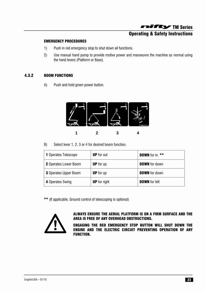
4.3.2 BOOM FUNCTIONS
A) Push and hold green power button.
1 2 3 4 B) Select lever 1, 2, 3 or 4 for desired boom function.
1 Operates Telescope UP for out DOWN for in. **
2 Operates Lower Boom UP for up DOWN for down
3 Operates Upper Boom UP for up DOWN for down
4 Operates Swing UP for right DOWN for left
** (If applicable, Ground control of telescoping is optional)
ALWAYS ENSURE THE AERIAL PLATFORM IS ON A FIRM SURFACE AND THE AREA IS FREE OF ANY OVERHEAD OBSTRUCTIONS.
ENGAGING THE RED EMERGENCY STOP BUTTON WILL SHUT DOWN THE ENGINE AND THE ELECTRIC CIRCUIT PREVENTING OPERATION OF ANY FUNCTION.
TM Series Operating & Safety Instructions
English/USA – 01/10 24
4.4 BASKET CONTROL OPERATION
NEVER START THE NIFTYLIFT IF YOU SMELL GASOLINE, LIQUID PROPANE OR DIESEL. THESE FUELS ARE FLAMMABLE.
BEFORE OPERATING THE NIFTYLIFT ENSURE THAT EACH OPERATOR HAS READ AND FULLY UNDERSTOOD THE OPERATING MANUAL. FAILURE TO DO SO MAY RESULT IN DEATH OR SERIOUS INJURY.
***FOR COLD START PROCEDURES SEE SECTION 4.3.1***
ALWAYS ALLOW THE ENGINE TO WARM UP BEFORE OPERATING.
4.4.1 BASKET CONTROL INSTRUCTIONS
ALL MODELS
1) NEVER exceed the maximum basket capacity.
2) Check below, above and around the platform for any obstruction or hazards before operating any function.
3) Ensure all red emergency stops are out.
4) For hydraulic outrigger models (TM50H), remove the key from the ground control station (turn key anti-clockwise) and put the key in the basket control station and switch to “ON” (clockwise). For manual outrigger models (TM50M) turn the key switch at the ground control station to “Platform” (clockwise) then remove key and place in the basket control station and switch to “ON” (clockwise)
5) Battery electric models go to step 11).
DIESEL ENGINE OR Bl ENERGY MODELS ONLY
6) Ensure that the main engine ignition switch is “ON”. Turn the “Engine Start” switch on the platform control box clockwise and the engine will fire.
7) Go to step 11). Note – Unless the diesel engine is running, the TM50H will automatically default to the primary power source (usually battery).
GASOLINE ENGINE OR GASOLINE/ELECTRIC MODELS ONLY
8) Ensure that the fuel tap is turned to the “ON” position and that the main engine ignition switch is “ON”. Turn the “Engine Start” switch on the platform control box clockwise and the engine will fire.
9) Go to step 11). Note – Unless the gasoline engine is running, the TM50 will automatically default to the primary power source (usually battery)
10) If the engine is too cold to start from the platform, try starting from the ground controls as described in step 8) of the ground control operation section (4.3.1).
TM Series Operating & Safety Instructions
English/USA – 01/10 25
ALL MODELS
11) Push and hold green power button.
12) Select the boom function required and operate hand levers in full accordance with manufacturers Operating and Safety manual.
13) When not in use return machine to stowed position, fully raise and stow all outriggers, turn the key to the “OFF” position (anti-clockwise), remove key and chock wheels.
EMERGENCY PROCEDURES
1) Push in red emergency stop to shut down all functions.
2) Use manual hand pump to provide motive power and manoeuvre the machine as normal using the hand levers (Platform or Base).
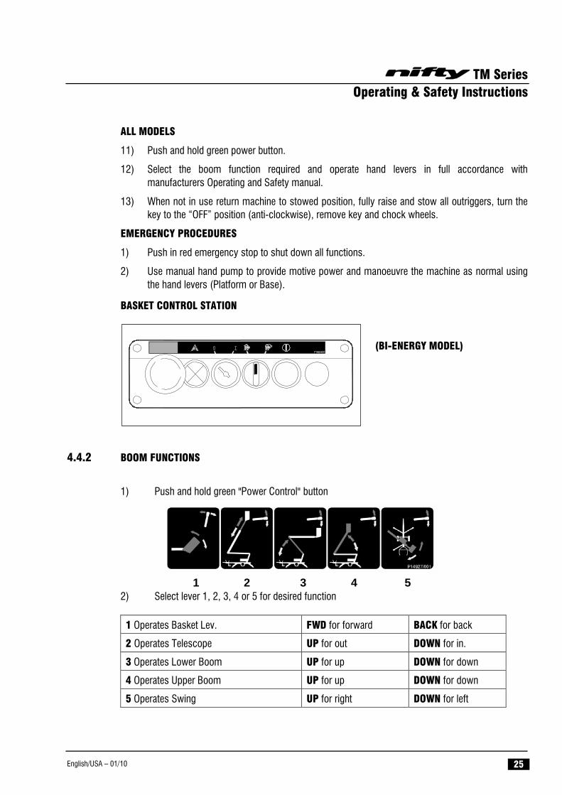
BASKET CONTROL STATION
(BI-ENERGY MODEL)
4.4.2 BOOM FUNCTIONS
1) Push and hold green "Power Control" button
1 2 3 4 5
2) Select lever 1, 2, 3, 4 or 5 for desired function
1 Operates Basket Lev. FWD for forward BACK for back
2 Operates Telescope UP for out DOWN for in.
3 Operates Lower Boom UP for up DOWN for down
4 Operates Upper Boom UP for up DOWN for down
5 Operates Swing UP for right DOWN for left
TM Series Operating & Safety Instructions
English/USA – 01/10 26
4.5 BATTERIES AND CHARGING
BATTERIES MUST BE RECHARGED IN A WELL-VENTILATED AREA FREE OF FLAME, SPARKS OR OTHER HAZARDS THAT MAY CAUSE EXPLOSION. HIGHLY EXPLOSIVE HYDROGEN GAS IS PRODUCED DURING THE CHARGING PROCESS.
1) Recharge batteries at the end of every working day or shift.
(Note: To recharge batteries fully from flat takes approx. 12 Hours, this consists of 8 hours bulk charging plus 4 hours equalisation).
2) Plug charger into suitable power 110 volt supply (see Charging Limitations).
3) Take note of the indicators provided:
DIGITAL CHARGER
Pulsing Green 50% LED - Batteries are charging and between 0 & 50% capacity. Constant Green 50% LED and pulsing Green 75% LED - Batteries are charging and between
50% & 75% capacity. Constant Green 50% & 75% LED’s, plus pulsing Green 100% LED - Batteries are charging
and between 75% & 100% capacity. Constant Green 50%, 75% % 100% LED’s – batteries are fully charged. Red Gel lamp – Only applicable to sealed type batteries.
IF USING THE TRANSFORMER TYPE CHARGER, UNDER NO CIRCUMSTANCES SHOULD BATTERIES BE LEFT ON CHARGE FOR PERIODS IN EXCESS OF 24 HOURS
4) DISCONNECT FROM POWER SUPPLY ONCE BATTERIES ARE FULLY CHARGED. The machine can now be left unattended, however, in the event of the machine being left unused for extensive periods then a 4 to 6 hour ‘top-up’ charge every 4 weeks is recommended. A ‘top-up’ charge the day before use ensures a full day of operation from the machine.
UNDER NO CIRCUMSTANCES SHOULD A MACHINE BE LEFT FULLY DISCHARGED AS SEVERE BATTERY DAMAGE CAN OCCUR IN A RELATIVELY SHORT TIME.
5) To avoid damage to charger disconnect from mains supply before using machine.
TM Series Operating & Safety Instructions
English/USA – 01/10 27
Note:
1) If the charger is reconnected to the power supply shortly after it has gone through its full charging cycle, the digital charger will show a Green 50% lamp, immediately followed by the Green 75% lamp. The charger would then repeat its complete cycle again at an accelerated rate, depending on the time difference between connection, reconnection and level of battery charge.
2) Some machines are fitted with a Battery Management System, which permanently monitors the condition of the batteries. When the batteries become discharged to 20% of their capacity the management system will begin to "shut down" the hydraulic power packs. This causes the drive/boom operating system to alternately stop and start, signalling to the operator that re-charging is necessary. However, there is sufficient power remaining to enable the operator to drive slowly to the nearest charging point.
Should the operator ignore the onset of the battery discharge warning the "shut down" of the motors will continue, until the machine is rendered in-operative. Immediate charging will then be required.
CHARGING LIMITATIONS
Digital Charger: - The capacity of the 110V supply must be capable of 2kW (18A current); hence a small hand-tool transformer will not operate the battery charger.
Digital Charger Fault Display
Note; If a fault occurs, the charger emits an audible warning. In addition, if the fault is rectified the charger will restart automatically.
Attention should also be given to the use of extension cables as power leads. Excessive cable lengths from the supply point to the battery charger will result in significant voltage drop, leading to a reduction in the chargers efficiency. In addition, inadequate sized cable cores will have a limiting effect on its current carrying capacity, which will again lead to a reduction in the chargers efficiency. Both of these can result in over-heating of the cable increasing the risk of fire, short circuits or damage to the components themselves.
LED status Description
Fault
3 green LED’s blink once simultaneously
Output is open or short, output voltage is over limit or output terminals are reversed
3 green LED’s blink twice simultaneously
Input voltage not within range
3 green LED’s blink three times simultaneously
Internal temperature charger limit exceeded
3 green LED’s blink four times simultaneously
Output current limit exceeded
Warning Green 100% LED blinks 18 hour timer has deactivated charger due to battery problem
TM Series Operating & Safety Instructions
English/USA – 01/10 28
Either charger requires a minimum battery voltage of 4.5 volts per battery (overall for two batteries 9 volts, for 4 batteries 19 volts for 8 batteries 38 volts). If the voltage is below these values then the charger will not function correctly (Transformer Charger will not detect batteries to begin charge). If the batteries have fallen to such a poor state they will have to be removed from the machine and charged individually with an independent charger until the optimum voltage has been reached. This is best performed at very low currents to ‘recover’ the batteries if sulphation has already started i.e. a ‘trickle’ charger. This can take several hours, possibly days. Careful monitoring of the rise of battery voltage will indicate when recovery has been achieved.
TOPPING UP
During the course of normal operation, the batteries should be inspected at least once a fortnight to check the level of electrolyte. During the end of charge, gassing takes place, which will cause a slight reduction in the volume of acid in the battery. This can be topped up with de-ionised water as required. During this inspection, it is useful to note any imbalance in the fluid levels. One indication of a faulty cell would be an increase in the loss of battery acid, which would then require more frequent topping up on that cell, or cells. Faulty cells can liberate excess hydrogen, even during normal operation, with the resulting risk of explosion if ignited. Any faulty batteries should be replaced as soon as possible with an equivalent sized and rated unit.
Note: BATTERIES CONTAIN ACID, therefore: - protective safety glasses and gloves (Appropriate PPE) MUST be worn whilst performing these checks.
TM Series Operating & Safety Instructions
English/USA – 01/10 29
4.6 TRANSPORTING, TOWING, STORAGE AND SETTING TO WORK 4.6.1 TRANSPORTING
If a work platform is to be moved over a longer distance, whether the machine is trailer mounted, vehicle mounted, self propelled or tracked, the following procedure should be read before restraints are attached to the machine. Cross loading is most frequently the cause of problems, as the method of loading is no longer in sight of our own personnel. The recommendations made herein should be passed on to subsequent carriers, such that the entire journey is carried out without incident.
• Always ensure the truck or trailer you are loading or towing the Niftylift with can carry it legally.
• If loading by crane the use of shackles and an adequately rated spreader beam, with four leg slings, is MANDATORY.
• When loading or un-loading from the side of the vehicle, the use of the forklift pockets to retain one of the forks is recommended. (If fitted). Spread the forks to their widest capacity, with due regard to the components fitted to the machine. Never forklift or crane an entire machine under the booms, always lift beneath the spine or under the ends of the axle mountings in the case of a self-propelled unit. Ensure forklift is adequately rated for the load to be carried.
• Once positioned on the transport carrier ratchet straps should be used to secure the machine. The machine should be positioned to allow easy access around the machine in transit, and to ensure that ‘creepage’ during transport does not permit the machine to come into contact with other goods being shipped, or the container itself. Some movement of the machine structure might occur during transit, which could lead to fretting or other damage.
• If the machine is equipped with a transit device such as a boom clamp etc, this should be securely applied.
• Strap booms carefully to constrain them from sideways movement. When using straps or chains, adequate packing should be applied to stop any damage to the structure and paintwork. Due regard of the movement of the straps or chains must be taken into account.
• Where a machine has designated points for strapping, lifting or forking, these can be used for tie-down duty. When they are absent, the major structure of the platform can be used, giving due consideration to the design and function of the area chosen. Where possible, use the spine of the machine or axle mounts over which to apply the holding down forces. Using a single plate, such as an outrigger or stabiliser support plate might be unsuitable. If the component was clearly not designed to accommodate a side load, one should not be applied.
• Under no circumstances should straps or chains be applied over booms or through the cage support structure or the cage itself. The relative strength of the carrying structure is not conducive to the massive forces capable of being applied through ratchet chains or slings. Severe damage to the steelwork can be caused, as well as deformation to sensitive mechanisms such as cage weigh assemblies, which would render them useless. Such catastrophic damage to say, an electronic load cell would require the component to be replaced before the machine would function.
TM Series Operating & Safety Instructions
English/USA – 01/10 30
4.6.2 TOWING
THE MAXIMUM RECOMMENDED TOWING SPEED OF A NIFTYLIFT IS 45 MPH WITH A VEHICLE THAT COMPLIES WITH ALL ROAD TRAFFIC REGULATIONS. SPEEDING MAY RESULT IN DEATH OR SERIOUS INJURY.
It is recommended that the maximum towing speed of 45mph be adhered to for the greatest safety. In other than perfect conditions it is sensible to further reduce your speed in order to ensure full control over your vehicle and trailer. The importance of the suitability of your towing vehicle must be stressed. The manufacturers' details concerning each model will give you recommended Gross Vehicle Weights (GVW) or Gross Train Weights (GTW) neither of which should be exceeded.
Brake Adjustment Trailer brakes are adjusted for gradual over-run braking on initial build. After being towed for the first week or 150 miles, the brake shoes will 'bed-in' and require adjustment for this wear. Adjust the brake shoe clearance and check the hand brake lever travel in accordance with the manufacturer’s instructions. Please contact Niftylift Service Department for the correct adjustment procedure for your specific brake/tow hitch combination.
POSITION TOWING VEHICLE AND TRAILER ON LEVEL GROUND BEFORE ATTEMPTING TO COUPLE/DE-COUPLE.
Coupling Instructions
1) Depress the trigger on the lever mechanism and lift the handle upwards and forward.
2) Place the unlocked coupling head onto the towing ball and apply slight downward pressure. The head will automatically lock onto the ball.
3) Ensure that the trigger has returned to its free position before attempting to tow, and that the coupling head is securely on the towing ball.
4) Connect the breakaway cable to the towing to the tow ball.
5) Connect the tow hitch chains to the towing vehicle chassis.
6) Connect the lighting plug to the vehicle and check the light functions.
7) Raise the jacking wheel to its stowed position and secure for transit.
De-coupling Instructions
1) Apply trailer handbrake and chock wheels.
2) Lower the jacking wheel to the ground. Disconnect the breakaway cable, chains and lighting plug.
3) Operate the handle by depressing the trigger and manually lift the coupling head clear of the towing ball or screw down the telescopic jockey wheel to achieve the same effect.
Handbrake Operation
1) To operate the trailer parking brakes pull the handbrake lever upwards and backwards. The spring loaded mechanism will engage and stay in the operated position until re-set.
2) To disengage the parking brakes, firmly grasp the handbrake lever and pull upwards. Depress the ratchet release button in the end of the handbrake lever and return the lever to the horizontal position. Care should be taken when operating the handbrake lever due to the forces involved in engaging the ratchet mechanism.
TM Series Operating & Safety Instructions
English/USA – 01/10 31
4.6.3 CRANEAGE
1) Observe all of the limitations relating to straps and chains stated above under ‘Transporting’. (Section 4.7.1)
2) When utilising the designated lifting points never apply a ‘snatch’ load, i.e. lift slowly to take up the load before raising. Similarly, do not drop machine when positioning after lifting.
3) If the machine is to be lifted by crane, use the designated lifting points and observe the recommendations regarding spreader beams. Individual drawings are available for each machine type, on request. (See list below.)
D80906 TM50H
4.6.4 STORAGE
If being stored for any length of time without use, then the machine should be thoroughly inspected for the following: -
1) Grease all bearings /slides, worm drives, etc.
2) Check batteries for electrolyte levels, state of charge, damage, dirt, etc. Never leave in a state of discharge for any length of time. If no use of the platform is intended, an occasional "top-up" charge of the batteries will serve to equalise their charge level.
3) Leave battery disconnect switch in OFF position to prevent discharge of batteries through leakage.
4) If machine is to be left on an incline, chock wheels to prevent creep.
5) If machine is to be left out-of-doors or in a hostile environment, cover with suitable weatherproof media to prevent deterioration.
4.6.5 SETTING TO WORK
Before use each day and at the beginning of each shift the machine shall be given a visual and functional test including, but not limited to, the following
1) Check all lubrication points for adequate application of grease, oil etc.
2) Inspect all threads for ease or operation.
3) Check level and quantity of oil. Remove any contaminants - water, etc.
4) Check batteries for electrolyte and state of charge.
5) Check electrics for damage and insulation.
6) Using base controls, cycle machine over complete envelope in accordance with the Operating Instructions. Cure any defects.
TM Series Operating & Safety Instructions
English/USA – 01/10 32
7) Ensure that all safety devices and controls operate in accordance with the instructions.
8) If necessary, perform a load test to establish the machine stability before putting the machine to work.
9) On completion of an extended period of road transport, the machine might need additional inspection to identify any transit degradation, which could render the machine unsafe. Perform a P.D.I. inspection on the unit before it enters service. Record any faults found and rectify them immediately.
10) If left un-attended for an extended period, it is likely that the hydraulic basket levelling will become un-pressurised. Normal operation is then lost, with a noticeable delay in the forwards or backwards motion as the booms move. To restore normal function, the basket needs to be fully levelled forwards and backwards, using the basket-levelling lever whilst not standing in the basket (i.e. with the operator standing adjacent to the basket side whilst simultaneously operating the lever and green button to move the basket). Take care not to become trapped between the moving basket and a fixed object, and ensure those around you are clear of the moving basket. When the system has been charged in both directions, the basket levelling function should be restored. If the system operates but is ‘jerky’ in either direction, this indicates air in the system. Repeat the procedure as described above until the movements are smooth and un-interrupted. If in doubt, contact our Service Department for further advice.
Niftylift Limited is not liable for any third party damage caused during transport. Careful attention to correct procedures will prevent many of the small snags that can happen in transit. Re-work is both expensive and time consuming. A defective machine arriving at the place of work is a poor advertisement for our product, the company’s reputation and those of our dealers and clients. The responsibility for safe and damage-free transport rests with the haulier or his representatives.
TM Series Operating & Safety Instructions
English/USA – 01/10 33
4.7 TRACTION DRIVE
On those trailer machines equipped primarily with fixed width axles, a traction drive system is an available option. This function allows the machine to be manoeuvred by one man, and provides the machine with the capability of ascending or descending a slope of 10% (5.7 degrees). Slopes in excess of this angle should not be attempted and a towing vehicle used instead.
The traction system is hydraulically driven, the supply being taken from the same power source as the base machine. The drive speeds and gradeability are therefore linked into the available power from the vehicle prime mover. The engagement of the traction system is also hydraulic, using a single hand lever to bring the drive cradles into contact with the road wheels. The control of the traction function is then possible from a single joystick permitting the machine to be moved forwards, backwards and steered on either side.
4.7.1 ENGAGING DRIVE
1) Before engaging the traction drive system, ensure that the machine is de-coupled from the towing vehicle, the jockey wheel deployed and securely fixed, and the parking handbrake is fully engaged.
2) Check that all of the emergency stops are released, i.e. ‘Out’, and that the Base Key switch is in the ‘On’ position, thereby directing the electrical feed to the drive joystick and outrigger station.
3) The Drive joystick has a single pushbutton located on the handle. Pushing and holding this button allows the power unit to produce hydraulic flow, which is directed to the drive manifold. It is not necessary to operate the jack selector lever, as this would deviate the hydraulic flow to the outrigger manifold and render the drive inoperative.
4) Whilst holding the joystick button and keeping the drive lever in the upright position, it is possible to use the third horizontal control lever to engage the traction drive. By pulling the lever upwards, the engagement cylinder will rotate the twin drive motors until the cradles come into contact with the road wheels. This function is pressure protected, and the lever should be held to allow the cradles to ‘push’ into the pneumatic tyres for best grip when driving. This pressure is set to 80 bar in the factory, and should not need adjustment.
5) When the engagement cylinder achieves full travel and the cradles are in adequate contact with the road wheels, the lever and drive button can be released, locking the engagement cylinder in this position. Only then should the parking handbrake be released, holding the machine on the traction drive assembly.
6) The machine can now be manoeuvred using the drive joystick, holding the button whilst moving the joystick in the direction of travel. It should be noted that the machine drives in the direction the handle is moved, such that if the joystick is released, the machine will not drive towards the direction the lever was being pulled. This decreases the risk of entrapment of the operator. To halt the drive function, release either the joystick, which will return to the centralised ‘Off’ position, or release the button to stop the hydraulic flow. The Emergency Stops can be similarly used to halt the machine drive at any time.
TM Series Operating & Safety Instructions
English/USA – 01/10 34
4.7.2 DISENGAGING DRIVE
1) Unless the machine has been manoeuvred to allow it to be coupled to a towing vehicle (as described in the appropriate section of this handbook), before disengaging the traction drive system the parking handbrake must be fully engaged. On no account disengage the traction drive system unless the handbrake is engaged, the wheels are securely chocked or the machine is connected to a towing vehicle. It is also recommended that the machine be positioned on flat, level ground before the drive system is disengaged.
2) Push and hold the drive joystick button to develop hydraulic flow, and using the third horizontal lever push downwards to retract the engagement cylinder. The traction drive cradles will swing clear of the road wheels, which should be allowed to travel outwards to their fullest extent. Releasing the third lever will then lock them in the retracted position, ready for towing.
On no account should the machine be towed with the traction drive system still engaged – serious damage may result.
Do not use the traction drive as a brake – the parking handbrake must be utilised for this purpose.
Never disengage the traction drive unless the handbrake is engaged, OR the wheels chocked, OR the machine directly and securely connected to a suitable towing vehicle.
Always position the machine on flat, level ground before disengaging the traction drive system.
Do not engage or disengage the traction system whilst on the move. Stop the machine first and engage the handbrake.
It is recommended that any slopes be approached in the direction that allows the tow hitch to be lower than the rest of the machine, ensuring that the jacking wheel keeps adequate weight throughout. Descending a slope with the tow hitch highest might allow the machine to tip backwards, particularly if a sudden stop is made. To maximize the residual load on the jockey wheel, allow the tow hitch to run as low as possible to the ground whilst supporting the nose weight on the retracted jacking wheel.
Do not ride on the machine whilst using the traction drive, nor stand inside the machine structure as serious injury might occur.
TM Series Operating & Safety Instructions
English/USA – 01/10 35
5 Emergency Controls
5.1 GENERAL
CHECKING THE OPERATION OF THE EMERGENCY CONTROLS EVERY DAY AND/OR BEFORE EACH SHIFT IS AN ESSENTIAL PART OF THE OPERATOR'S DUTIES
The operator and all ground personnel must be thoroughly familiar with the location and operation of the EMERGENCY CONTROLS.
5.2 IN THE EVENT OF AN INCAPACITATED OPERATOR
For the manual outrigger option (TM50M) - turn the key switch selector at ground control station to “Ground” (anti-clockwise). Then lower on the ground controls as detailed under section 4.3 Ground Control Operation. For the hydraulic outrigger option (TM50H) place the spare key in the ground control station and switch “ON” (clockwise). Then lower on the ground controls as detailed under section 4.3 Ground Control Operation.
5.3 IN THE EVENT OF MACHINE FAILURE
Operate manual hand pump (located adjacent to the base controls) and lower basket to the ground using either basket or base controls. If initial movement of the machine allows the master alarm to reset, normal controls will be available. This is then the fastest method of lowering the platform to the ground.
5.4 INCIDENT NOTIFICATION
It is a mandatory requirement that any accident or incident involving a Niftylift, regardless of whether any party received injury or property was damaged is reported by telephone directly to Niftylift. Failure to do so may render any warranty on the machine void.

TM Series Operating & Safety Instructions
English/USA – 01/10 36
6 Responsibilities 6.1 CHANGES IN OWNERSHIP
When a change of ownership of a Niftylift occurs, it shall be the responsibility of the seller to notify Niftylift direct of the unit, model and serial number and the name and address of the new owner within 60 days. This important step is required so that all future Technical Bulletins are able to reach the registered owner of each machine without delay. Please note warranties are not transferable.
6.2 MANUAL OF RESPONSIBILITIES
You are required by ANSI/SIA 92.2 1990, to read and understand your responsibilities before you use or operate this aerial platform.
Please read the enclosed document, as failure to do so could result in death or serious injury.
Wherever any contradiction may appear, the Manual of Responsibilities shall take precedence over all other documents.
TM Series Operating & Safety Instructions
English/USA – 01/10 37
6.3 Inspection/Service/Pre-Hire Check list
MACHINE SERIAL NO
TOWING PASS FAIL N/A Operation of tow coupling
Operation of handbrake
Operation of jacking wheel
OUTRIGGERS Micro-switches secure
Locating pins operating freely and oiled
Outriggers operate smoothly
Operation of each micro-switch and klaxon (if fitted)
Operation of outrigger control valve and buttons
Operation of each hydraulic outrigger
Operation of each micro-switch including siren
Operation of boom rest micro-switch
AXLES, WHEELS AND BRAKES Axles slide freely (90/120), or are secure (170/180)
Wheels are secure, tyre condition acceptable
Wheel bearings OK
Fenders are secure
Locating pins operate freely and oiled
Lock bolts are tight
Wheels spin freely when handbrake is released
Brakes come on equally when handbrake is applied
Brake linkages and cables secure
Brake shoe wear not excessive
Breakaway cable fitted and operable
Tail lights fitted, lights function
Tyre pressure correct
Wheel nut torque correct
BASE Operation of base control valve and buttons
Operation of all booms over full range
Cylinders are silent
Platform is level over full range
Booms, levelling rods not damaged or distorted
Booms, levelling rods, cylinders not fouling
Hoses not tight, kinked or fouled
Operation of manual hand pump
TM Series Operating & Safety Instructions
English/USA – 01/10 38
BOOM ROTATION PASS FAIL N/A Boom rotation assembly and motor are secure
Worm/wheel mesh correct, no excessive wear
No end float of worm in housing
Rotation gear wheel bolts secured
Rotation gear guards secure
BASKET Operation of control valve and buttons
Operation of all booms over full range
Cylinders are silent
Basket levelling over full range
Boom Rotation is smooth over full range
Operation of boom 4 over full range (if fitted)
INTERNAL (POWER PACK) Power pack and all components secure
All cables and terminals secure
All hose connections secure
Hoses not kinked or fouled
Charger/control box secure
Battery secure
Electrolyte level and specific gravity
Charger operation
Hydraulic oil level
FINISH Operation of boom clamp
Pivot pin tag bolts
Correct decals, all visible
Canopy/bonnets
Grease nipples (Feet, Knuckle, Centre Post)
(Tow coupling, Boom rotation Gear, Boom 4-170)
LEAK CHECK Cylinders (Lift, outriggers, Telescope, Levelling)
Control valves
Check valves
Power pack/pump
Boom rotation motor
Hose connections
Comments, remedial work required etc;
INSPECTED BY: DATE: / /