Embed Size (px)
Citation preview
REVISION DATE 10-28-09 INST. NO. IT-5436 A REVISED 02-26-10 Copyright © 2009 SPX Corporation PAGE 1 OF 21
OPERATING AND MAINTENANCE INSTRUCTIONS FOR NETTCO i-SERIES
SECTION 1 - INITIAL INSPECTION, SHIPPING ARRANGEMENTS AND STORAGE
1.1 Check the shipping crates and your LIGHTNIN equipment for possible shipping damage. Report any damage immediately to the carrier and our factory.
1.2 The mixer and impellers are packed together. The impeller shaft, if over 48 inches (1200mm) long, is packed in a separate container.
1.3 Do not remove any protective coatings or wrappings until the mixer is ready to be put into service. If the mixer is to be stored, store only in an indoor, clean, dry location with controlled temperatures of 59 F to 104 F (15 C to 40 C). When gear drive models have been stored for more than one year, the gear lubricant should be replaced (see lubrication instructions). Motor shafts are to be rotated manually every month, at least 10 to 15 revolutions.
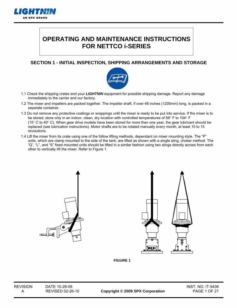
1.4 Lift the mixer from its crate using one of the follow lifting methods, dependant on mixer mounting style. The “P” units, which are clamp mounted to the side of the tank, are lifted as shown with a single sling, choker method. The “Q”, “L”, and “S” fixed mounted units should be lifted in a similar fashion using two slings directly across from each other to vertically lift the mixer. Refer to Figure 1.
FIGURE 1
REVISION DATE 10-28-09 INST. NO. IT-5436 A REVISED 02-26-10 Copyright © 2009 SPX Corporation PAGE 2 OF 21
WARNING: EYE PROTECTION MUST BE WORN AT ALL TIMES WHILE SERVICING THIS MIXER.
SECTION 2 - MIXER MOUNTING CONFIGURATIONS
2.1 Refer to Dimension Drawing for mounting configuration.
a. Impeller Position Recommendations:
Single Impeller Dual Impeller
Basic Position Impeller Mid Batch Lower Impeller: 1D Off Bottom
Upper Impeller: 1D Spacing
Alternate 0.75D < = OB < = 1.5D Lower Impeller: 0.75D < = OB < = 1.5D
Upper Impeller: 0.75D < = SP < = 1.5D
D: Impeller Diameter OB: Impeller Off Bottom
SP: Impeller Spacing
2.2 Lock-out power before positioning mixer, and review safety instructions before starting mixer.
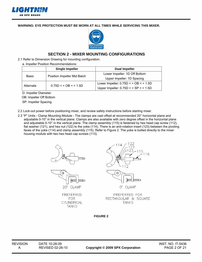
2.3 “P” Units - Clamp Mounting Module - The clamps are cast offset at recommended 20° horizontal plane and adjustable 0-10° in the vertical plane. Clamps are also available with zero degree offset in the horizontal plane and adjustable 0-10° in the vertical plane. The clamp assembly (115) is fastened by hex head cap screw (112), flat washer (121), and hex nut (122) to the yoke (114). There is an anti-rotation insert (123) between the pivoting faces of the yoke (114) and clamp assembly (115). Refer to Figure 2. The yoke is bolted directly to the mixer housing module with two hex head cap screws (113).
FIGURE 2
REVISION DATE 10-28-09 INST. NO. IT-5436 A REVISED 02-26-10 Copyright © 2009 SPX Corporation PAGE 3 OF 21
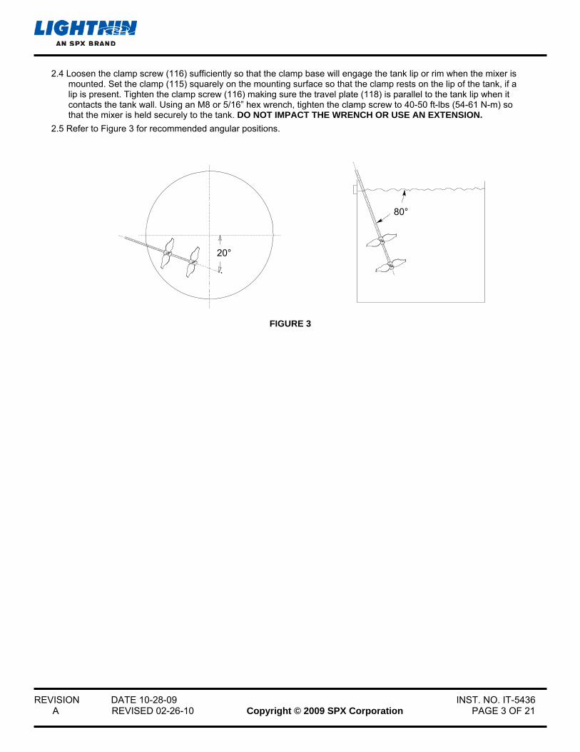
2.4 Loosen the clamp screw (116) sufficiently so that the clamp base will engage the tank lip or rim when the mixer is mounted. Set the clamp (115) squarely on the mounting surface so that the clamp rests on the lip of the tank, if a lip is present. Tighten the clamp screw (116) making sure the travel plate (118) is parallel to the tank lip when it contacts the tank wall. Using an M8 or 5/16” hex wrench, tighten the clamp screw to 40-50 ft-lbs (54-61 N-m) so that the mixer is held securely to the tank. DO NOT IMPACT THE WRENCH OR USE AN EXTENSION.
2.5 Refer to Figure 3 for recommended angular positions.
FIGURE 3
20°
80°
REVISION DATE 10-28-09 INST. NO. IT-5436 A REVISED 02-26-10 Copyright © 2009 SPX Corporation PAGE 4 OF 21
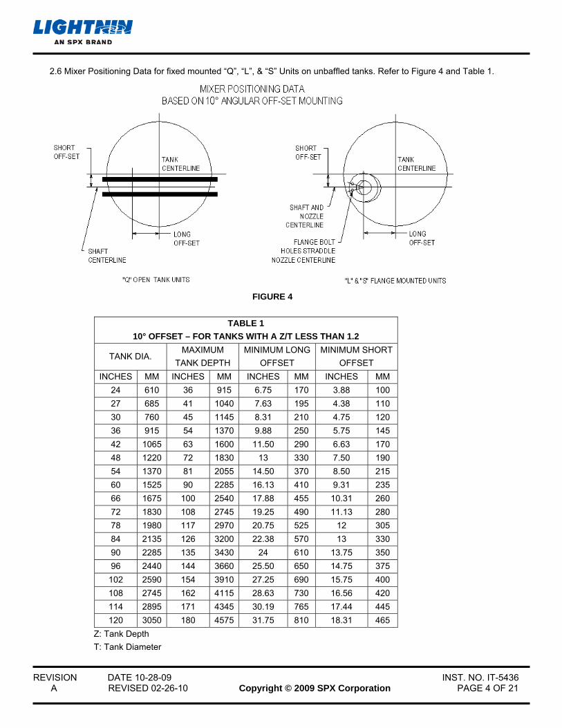
2.6 Mixer Positioning Data for fixed mounted “Q”, “L”, & “S” Units on unbaffled tanks. Refer to Figure 4 and Table 1.
FIGURE 4
TABLE 1
10° OFFSET – FOR TANKS WITH A Z/T LESS THAN 1.2
TANK DIA. MAXIMUM
TANK DEPTH
MINIMUM LONG
OFFSET
MINIMUM SHORT
OFFSET
INCHES MM INCHES MM INCHES MM INCHES MM
24 610 36 915 6.75 170 3.88 100
27 685 41 1040 7.63 195 4.38 110
30 760 45 1145 8.31 210 4.75 120
36 915 54 1370 9.88 250 5.75 145
42 1065 63 1600 11.50 290 6.63 170
48 1220 72 1830 13 330 7.50 190
54 1370 81 2055 14.50 370 8.50 215
60 1525 90 2285 16.13 410 9.31 235
66 1675 100 2540 17.88 455 10.31 260
72 1830 108 2745 19.25 490 11.13 280
78 1980 117 2970 20.75 525 12 305
84 2135 126 3200 22.38 570 13 330
90 2285 135 3430 24 610 13.75 350
96 2440 144 3660 25.50 650 14.75 375
102 2590 154 3910 27.25 690 15.75 400
108 2745 162 4115 28.63 730 16.56 420
114 2895 171 4345 30.19 765 17.44 445
120 3050 180 4575 31.75 810 18.31 465
Z: Tank Depth
T: Tank Diameter
REVISION DATE 10-28-09 INST. NO. IT-5436 A REVISED 02-26-10 Copyright © 2009 SPX Corporation PAGE 5 OF 21
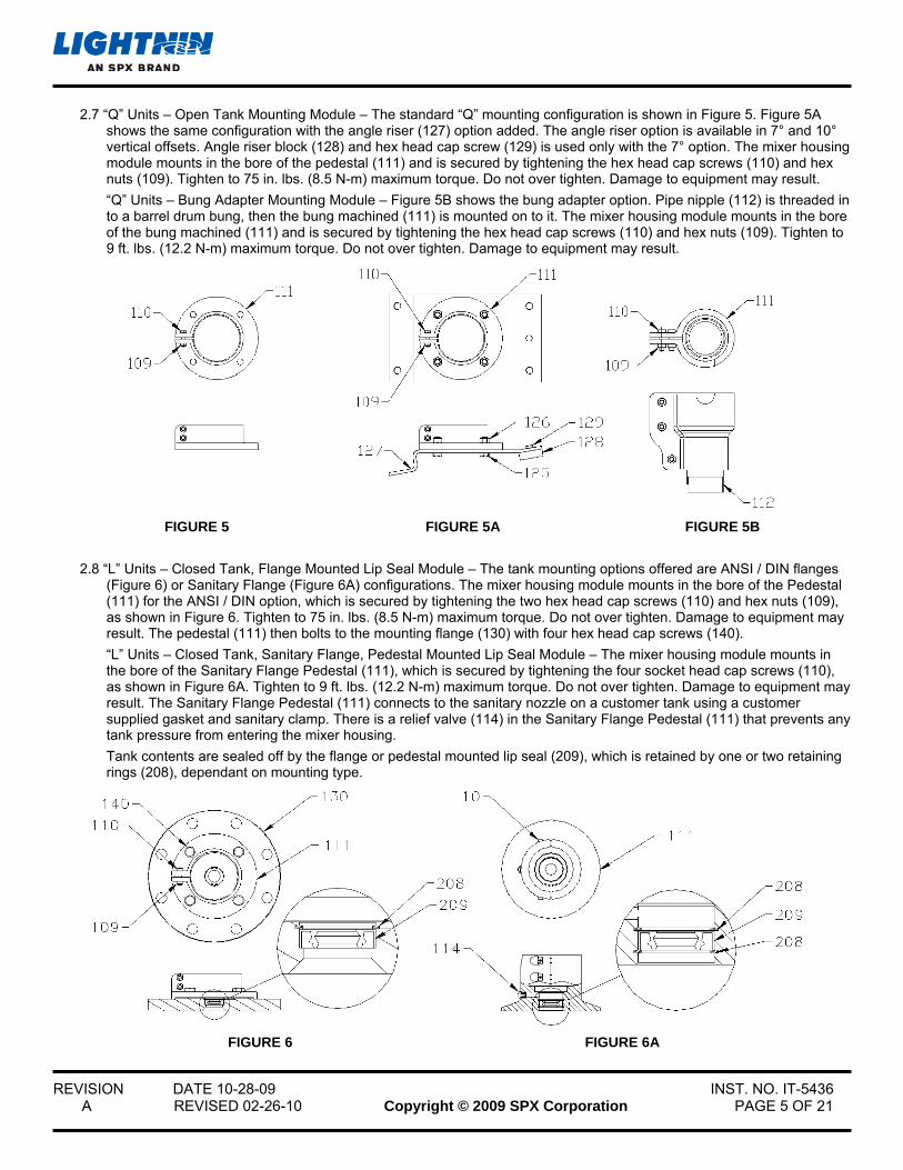
2.7 “Q” Units – Open Tank Mounting Module – The standard “Q” mounting configuration is shown in Figure 5. Figure 5A shows the same configuration with the angle riser (127) option added. The angle riser option is available in 7° and 10° vertical offsets. Angle riser block (128) and hex head cap screw (129) is used only with the 7° option. The mixer housing module mounts in the bore of the pedestal (111) and is secured by tightening the hex head cap screws (110) and hex nuts (109). Tighten to 75 in. lbs. (8.5 N-m) maximum torque. Do not over tighten. Damage to equipment may result.
“Q” Units – Bung Adapter Mounting Module – Figure 5B shows the bung adapter option. Pipe nipple (112) is threaded in to a barrel drum bung, then the bung machined (111) is mounted on to it. The mixer housing module mounts in the bore of the bung machined (111) and is secured by tightening the hex head cap screws (110) and hex nuts (109). Tighten to 9 ft. lbs. (12.2 N-m) maximum torque. Do not over tighten. Damage to equipment may result.
FIGURE 5 FIGURE 5A FIGURE 5B
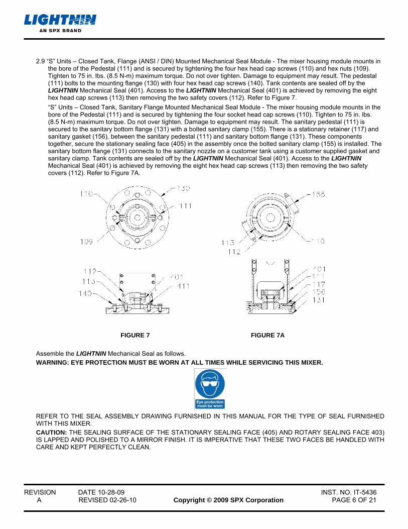
2.8 “L” Units – Closed Tank, Flange Mounted Lip Seal Module – The tank mounting options offered are ANSI / DIN flanges (Figure 6) or Sanitary Flange (Figure 6A) configurations. The mixer housing module mounts in the bore of the Pedestal (111) for the ANSI / DIN option, which is secured by tightening the two hex head cap screws (110) and hex nuts (109), as shown in Figure 6. Tighten to 75 in. lbs. (8.5 N-m) maximum torque. Do not over tighten. Damage to equipment may result. The pedestal (111) then bolts to the mounting flange (130) with four hex head cap screws (140).
“L” Units – Closed Tank, Sanitary Flange, Pedestal Mounted Lip Seal Module – The mixer housing module mounts in the bore of the Sanitary Flange Pedestal (111), which is secured by tightening the four socket head cap screws (110), as shown in Figure 6A. Tighten to 9 ft. lbs. (12.2 N-m) maximum torque. Do not over tighten. Damage to equipment may result. The Sanitary Flange Pedestal (111) connects to the sanitary nozzle on a customer tank using a customer supplied gasket and sanitary clamp. There is a relief valve (114) in the Sanitary Flange Pedestal (111) that prevents any tank pressure from entering the mixer housing.
Tank contents are sealed off by the flange or pedestal mounted lip seal (209), which is retained by one or two retaining rings (208), dependant on mounting type.
FIGURE 6 FIGURE 6A
REVISION DATE 10-28-09 INST. NO. IT-5436 A REVISED 02-26-10 Copyright © 2009 SPX Corporation PAGE 6 OF 21
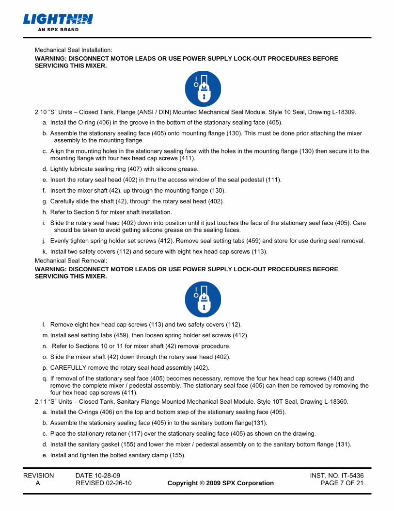
2.9 “S” Units – Closed Tank, Flange (ANSI / DIN) Mounted Mechanical Seal Module - The mixer housing module mounts in the bore of the Pedestal (111) and is secured by tightening the four hex head cap screws (110) and hex nuts (109). Tighten to 75 in. lbs. (8.5 N-m) maximum torque. Do not over tighten. Damage to equipment may result. The pedestal (111) bolts to the mounting flange (130) with four hex head cap screws (140). Tank contents are sealed off by the LIGHTNIN Mechanical Seal (401). Access to the LIGHTNIN Mechanical Seal (401) is achieved by removing the eight hex head cap screws (113) then removing the two safety covers (112). Refer to Figure 7.
“S” Units – Closed Tank, Sanitary Flange Mounted Mechanical Seal Module - The mixer housing module mounts in the bore of the Pedestal (111) and is secured by tightening the four socket head cap screws (110). Tighten to 75 in. lbs. (8.5 N-m) maximum torque. Do not over tighten. Damage to equipment may result. The sanitary pedestal (111) is secured to the sanitary bottom flange (131) with a bolted sanitary clamp (155). There is a stationary retainer (117) and sanitary gasket (156), between the sanitary pedestal (111) and sanitary bottom flange (131). These components together, secure the stationary sealing face (405) in the assembly once the bolted sanitary clamp (155) is installed. The sanitary bottom flange (131) connects to the sanitary nozzle on a customer tank using a customer supplied gasket and sanitary clamp. Tank contents are sealed off by the LIGHTNIN Mechanical Seal (401). Access to the LIGHTNIN Mechanical Seal (401) is achieved by removing the eight hex head cap screws (113) then removing the two safety covers (112). Refer to Figure 7A.
FIGURE 7 FIGURE 7A
Assemble the LIGHTNIN Mechanical Seal as follows.
WARNING: EYE PROTECTION MUST BE WORN AT ALL TIMES WHILE SERVICING THIS MIXER.
REFER TO THE SEAL ASSEMBLY DRAWING FURNISHED IN THIS MANUAL FOR THE TYPE OF SEAL FURNISHED WITH THIS MIXER.
CAUTION: THE SEALING SURFACE OF THE STATIONARY SEALING FACE (405) AND ROTARY SEALING FACE 403) IS LAPPED AND POLISHED TO A MIRROR FINISH. IT IS IMPERATIVE THAT THESE TWO FACES BE HANDLED WITH CARE AND KEPT PERFECTLY CLEAN.
REVISION DATE 10-28-09 INST. NO. IT-5436 A REVISED 02-26-10 Copyright © 2009 SPX Corporation PAGE 7 OF 21
Mechanical Seal Installation:
WARNING: DISCONNECT MOTOR LEADS OR USE POWER SUPPLY LOCK-OUT PROCEDURES BEFORE SERVICING THIS MIXER.
2.10 “S” Units – Closed Tank, Flange (ANSI / DIN) Mounted Mechanical Seal Module. Style 10 Seal, Drawing L-18309.
a. Install the O-ring (406) in the groove in the bottom of the stationary sealing face (405).
b. Assemble the stationary sealing face (405) onto mounting flange (130). This must be done prior attaching the mixer assembly to the mounting flange.
c. Align the mounting holes in the stationary sealing face with the holes in the mounting flange (130) then secure it to the mounting flange with four hex head cap screws (411).
d. Lightly lubricate sealing ring (407) with silicone grease.
e. Insert the rotary seal head (402) in thru the access window of the seal pedestal (111).
f. Insert the mixer shaft (42), up through the mounting flange (130).
g. Carefully slide the shaft (42), through the rotary seal head (402).
h. Refer to Section 5 for mixer shaft installation.
i. Slide the rotary seal head (402) down into position until it just touches the face of the stationary seal face (405). Care should be taken to avoid getting silicone grease on the sealing faces.
j. Evenly tighten spring holder set screws (412). Remove seal setting tabs (459) and store for use during seal removal.
k. Install two safety covers (112) and secure with eight hex head cap screws (113).
Mechanical Seal Removal:
WARNING: DISCONNECT MOTOR LEADS OR USE POWER SUPPLY LOCK-OUT PROCEDURES BEFORE SERVICING THIS MIXER.
l. Remove eight hex head cap screws (113) and two safety covers (112).
m. Install seal setting tabs (459), then loosen spring holder set screws (412).
n. Refer to Sections 10 or 11 for mixer shaft (42) removal procedure.
o. Slide the mixer shaft (42) down through the rotary seal head (402).
p. CAREFULLY remove the rotary seal head assembly (402).
q. If removal of the stationary seal face (405) becomes necessary, remove the four hex head cap screws (140) and remove the complete mixer / pedestal assembly. The stationary seal face (405) can then be removed by removing the four hex head cap screws (411).
2.11 “S” Units – Closed Tank, Sanitary Flange Mounted Mechanical Seal Module. Style 10T Seal, Drawing L-18360.
a. Install the O-rings (406) on the top and bottom step of the stationary sealing face (405).
b. Assemble the stationary sealing face (405) in to the sanitary bottom flange(131).
c. Place the stationary retainer (117) over the stationary sealing face (405) as shown on the drawing.
d. Install the sanitary gasket (155) and lower the mixer / pedestal assembly on to the sanitary bottom flange (131).
e. Install and tighten the bolted sanitary clamp (155).
REVISION DATE 10-28-09 INST. NO. IT-5436 A REVISED 02-26-10 Copyright © 2009 SPX Corporation PAGE 8 OF 21
f. Lightly lubricate sealing ring (407) with silicone grease.
g. Insert the rotary seal head (402) in thru the access window of the sanitary pedestal (111).
h. Insert the mixer shaft (42), up through the sanitary bottom flange (131).
i. Carefully slide the shaft (42), through the rotary seal head (402).
j. Refer to Section 5 for mixer shaft installation.
k. Slide the rotary seal head (402) down into position until it just touches the face of the stationary seal face (405). Care should be taken to avoid getting silicone grease on the sealing faces.
l. Evenly tighten spring holder set screws (412). Remove seal setting tabs (459) and store for use during seal removal.
m. Install two safety covers (112) and secure with eight hex head cap screws (113).
Mechanical Seal Removal:
WARNING: DISCONNECT MOTOR LEADS OR USE POWER SUPPLY LOCK-OUT PROCEDURES BEFORE SERVICING THIS MIXER.
n. Remove eight hex head cap screws (113) and two safety covers (112).
o. Install seal setting tabs (459), then loosen spring holder set screws (412).
p. Refer to Sections 10 or 11 for mixer shaft (42) removal procedure.
q. Slide the mixer shaft (42) down through the rotary seal head (402).
r. CAREFULLY remove the rotary seal head assembly (402).
s. If removal of the stationary seal face (405) becomes necessary, remove the bolted sanitary clamp (155), separate the mixer / pedestal assembly from the sanitary bottom flange (131), remove the stationary retainer (117), then remove the stationary seal face (405).
SECTION 3 – ELECTRIC MOTOR CONNECTIONS 3.1 Three Phase Motors:
a. All three phase motors must be field wired for proper rotation. If rotation does not agree with nameplate, reverse any two line leads.
b. Dual voltage motors can be wired for the desired voltage. Refer to the connection diagrams provided on the motor nameplate and inside the conduit box cover.
SECTION 4 – AIR MOTOR REQUIREMENTS AND LUBRICATION
REVISION DATE 10-28-09 INST. NO. IT-5436 A REVISED 02-26-10 Copyright © 2009 SPX Corporation PAGE 9 OF 21
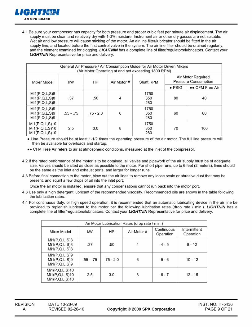
4.1 Be sure your compressor has capacity for both pressure and proper cubic feet per minute air displacement. The air supply must be clean and relatively dry with 1-3% moisture. Instrument air or other dry gasses are not suitable. Wet air and low pressure will cause sticking of the motor. An air line filter/lubricator should be fitted in the air supply line, and located before the first control valve in the system. The air line filter should be drained regularly, and the element examined for clogging. LIGHTNIN has a complete line of filter/regulators/lubricators. Contact your LIGHTNIN Representative for price and delivery.
General Air Pressure / Air Consumption Guide for Air Motor Driven Mixers (Air Motor Operating at and not exceeding 1800 RPM)
Air Motor Required Pressure Consumption Mixer Model kW HP Air Motor # Shaft RPM
● PSIG ●● CFM Free Air
Mi1(P,Q,L,S)8 Mi1(P,Q,L,S)8 Mi1(P,Q,L,S)8
.37 .50 4 1750 350 280
80 40
Mi1(P,Q,L,S)9 Mi1(P,Q,L,S)9 Mi1(P,Q,L,S)9
.55 - .75 .75 - 2.0 6 1750 350 280
60 60
Mi1(P,Q,L,S)10 Mi1(P,Q,L,S)10 Mi1(P,Q,L,S)10
2.5 3.0 8 1750 350 280
70 100
● Line Pressure should be at least 1-1/2 times the operating pressure of the air motor. The full line pressure will then be available for overloads and startup.
●● CFM Free Air refers to air at atmospheric conditions, measured at the inlet of the compressor.
4.2 If the rated performance of the motor is to be obtained, all valves and pipework of the air supply must be of adequate size. Valves should be sited as close as possible to the motor. For short pipe runs, up to 6 feet (2 meters), lines should be the same as the inlet and exhaust ports, and larger for longer runs.
4.3 Before final connection to the motor, blow out the air lines to remove any loose scale or abrasive dust that may be present, and squirt a few drops of oil into the inlet port.
Once the air motor is installed, ensure that any condensations cannot run back into the motor port.
4.3 Use only a high detergent lubricant of the recommended viscosity. Recommended oils are shown in the table following the lubrication rates.
4.4 For continuous duty, or high speed operation, it is recommended that an automatic lubricating device in the air line be provided to replenish lubricant to the motor per the following lubrication rates (drop rate / min.). LIGHTNIN has a complete line of filter/regulators/lubricators. Contact your LIGHTNIN Representative for price and delivery.
Air Motor Lubrication Rates (drop rate / min.)
Mixer Model kW HP Air Motor # Continuous Operation
Intermittent Operation
Mi1(P,Q,L,S)8 Mi1(P,Q,L,S)8 Mi1(P,Q,L,S)8
.37 .50 4 4 - 5 8 - 12
Mi1(P,Q,L,S)9 Mi1(P,Q,L,S)9 Mi1(P,Q,L,S)9
.55 - .75 .75 - 2.0 6 5 - 6 10 - 12
Mi1(P,Q,L,S)10 Mi1(P,Q,L,S)10 Mi1(P,Q,L,S)10
2.5 3.0 8 6 - 7 12 - 15
REVISION DATE 10-28-09 INST. NO. IT-5436 A REVISED 02-26-10 Copyright © 2009 SPX Corporation PAGE 10 OF 21
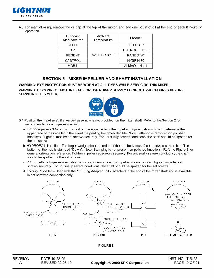
4.5 For manual oiling, remove the oil cap at the top of the motor, and add one squirt of oil at the end of each 8 hours of operation.
Lubricant Manufacturer
Ambient Temperature
Product
SHELL TELLUS 37
B.P. ENERGOL HL65
REGENT RANDO “A”
CASTROL HYSPIN 70
MOBIL
32° F to 100° F
ALMAOIL No. 1
SECTION 5 - MIXER IMPELLER AND SHAFT INSTALLATION WARNING: EYE PROTECTION MUST BE WORN AT ALL TIMES WHILE SERVICING THIS MIXER.
WARNING: DISCONNECT MOTOR LEADS OR USE POWER SUPPLY LOCK-OUT PROCEDURES BEFORE SERVICING THIS MIXER.
5.1 Position the impeller(s), if a welded assembly is not provided, on the mixer shaft. Refer to the Section 2 for
recommended dual impeller spacing.
a. FP100 impeller - “Motor End” is cast on the upper side of the impeller. Figure 8 shows how to determine the upper face of the impeller in the event the printing becomes illegible. Note: Lettering is removed on polished impellers. Tighten impeller set screws securely. For unusually severe conditions, the shaft should be spotted for the set screws.
b. HYDROFOIL impeller - The larger wedge shaped portion of the hub body must face up towards the mixer. The bottom of the hub is stamped “Down”. Note: Stamping is not present on polished impellers. Refer to Figure 8 for general orientation reference. Tighten impeller set screws securely. For unusually severe conditions, the shaft should be spotted for the set screws.
c. PBT impeller – Impeller orientation is not a concern since this impeller is symmetrical. Tighten impeller set screws securely. For unusually severe conditions, the shaft should be spotted for the set screws.
d. Folding Propeller – Used with the “Q” Bung Adapter units. Attached to the end of the mixer shaft and is available in set screwed connection only.
FIGURE 8
REVISION DATE 10-28-09 INST. NO. IT-5436 A REVISED 02-26-10 Copyright © 2009 SPX Corporation PAGE 11 OF 21
Shaft Installation:
Models: Mi1, Mi5 & Mi6 (P,Q,L) 1-6 and 8-10.
5.2 Before installing the mixer shaft (42), clean the mixer shaft end and drive quill (35) thoroughly. To install the mixer shaft, remove the access plug (97), and orient the drive quill so that the set screw (96) aligns with the access hole. Align the drive quill by inserting the mixer shaft (42) into the quill and rotate quill manually. Insert the mixer shaft into the quill bore as far as it will go. Draw up the set screw, rotating the shaft slightly back and forth to make sure the set screw (96) seats against the flat of the shaft. Tighten the set screw (96) to 29 ft-lbs (39 Nm). DO NOT IMPACT THE WRENCH OR USE AN EXTENSION. Re-install the access plug (97).
NOTE: A safety feature is provided by a slight taper in the flat on the impeller shaft. The shaft cannot drop out unless the set screw is intentionally loosened.
Models: Mi5 & Mi6S 1-6 and 8-10.
5.3 Remove the eight hex head cap screws (113) that secure the two safety covers (112) to the pedestal (111), then remove the safety covers (112). Before installing the mixer shaft (42), clean the mixer shaft end and drive quill (35) thoroughly. To install the mixer shaft, remove the access plug (97), and orient the drive quill so that the set screw (96) aligns with the access hole. Align the drive quill by inserting the mixer shaft (42) into the quill and rotate quill manually. Remove the mixer shaft (42) from the drive quill (35). Lightly lubricate sealing ring (407) in the rotary seal head (402) with silicone grease. Insert the rotary seal head (402) in thru the access window of the seal pedestal (111). Carefully slide the shaft (42), through the rotary seal head (402). Insert the mixer shaft into the quill bore as far as it will go. Draw up the set screw, rotating the shaft slightly back and forth to make sure the set screw (96) seats against the flat of the shaft. Tighten the set screw (96) to 29 ft-lbs (39 Nm). DO NOT IMPACT THE WRENCH OR USE AN EXTENSION. Re-install the access plug (97). Slide the rotary seal head (402) down into position until it just touches the face of the stationary seal face (405). Care should be taken to avoid getting silicone grease on the sealing faces. Evenly tighten spring holder set screws (412). Remove seal setting tabs (459) and store for use during seal removal. Install two safety covers (112) and secure with eight hex head cap screws (113).
NOTE: A safety feature is provided by a slight taper in the flat on the impeller shaft. The shaft cannot drop out unless the set screw is intentionally loosened.
Models: Mi1, Mi5 & Mi6 (Q,L) 7. (40mm Shaft Diameter)
5.4 Before installing the rigid upper shaft (40) clean the upper shaft end and drive quill (35) thoroughly. To install the rigid upper shaft, remove the two access plugs (97), and orient the drive quill so that the first two set screws (96) aligns with the access hole. To align the drive quill, insert the rigid upper shaft (40) into the quill and rotate quill manually. It will be necessary to rotate the quill to determine the location of the second set of set screws. This must be done in order to align the set screw locations with the flat locations on the rigid upper shaft (40). Insert the rigid upper shaft (40) into the quill bore as far as it will go. Draw up the set screws. Tighten the set screws (96) to 29 ft-lbs (39 Nm). DO NOT IMPACT THE WRENCH OR USE AN EXTENSION. Repeat for the second set of set screws. Re-install the access plugs (97). Connect the impeller shaft (42) to the rigid upper shaft (40) by bolting the coupling halves together using hex head cap screws (67) and hex nuts (69). Use care to prevent damage to the rabbets. Make sure the mating faces are flush and free of debris before torquing the hardware. Refer to Section 7, Table 2 for recommended torque values.
Models: Mi5 & Mi6S7. (40mm Shaft Diameter)
5.5 Remove the eight hex head cap screws (113) that secure the two safety covers (112) to the pedestal (111), then remove the safety covers (112). Before installing the rigid upper shaft (40), clean the upper shaft end and drive quill (35) thoroughly. To install the rigid upper shaft, remove the two access plugs (97), and orient the drive quill so that the first two set screws (96) aligns with the access hole. To align the drive quill, insert the rigid upper shaft (40) into the quill and rotate quill manually. It will be necessary to rotate the quill to determine the location of the second set of set screws. This must be done in order to align the set screw locations with the flat locations on the rigid upper shaft (40). Remove the rigid upper shaft (40) from the drive quill (35). Lightly lubricate sealing ring (407) in the rotary seal head (402) with silicone grease. Insert the rotary seal head (402) in thru the access window of the seal pedestal (111). Carefully slide the rigid upper shaft (40), through the rotary seal head (402). Insert the upper shaft into the quill bore as far as it will go. Draw up the set screws. Tighten the set screws (96) to 29 ft-lbs (39 Nm). DO NOT IMPACT THE WRENCH OR USE AN EXTENSION. Repeat for the second set of set screws. Re-install the access plugs (97). Slide the rotary seal head (402) down into position until it just touches the face of the stationary seal face (405). Care should be taken to avoid getting silicone grease on the sealing faces. Evenly tighten spring holder set screws (412). Remove seal setting tabs (459) and store for use during seal removal. Install two safety covers (112) and secure with eight hex head cap screws (113). Connect the impeller
REVISION DATE 10-28-09 INST. NO. IT-5436 A REVISED 02-26-10 Copyright © 2009 SPX Corporation PAGE 12 OF 21
shaft (42) to the rigid upper shaft (40) by bolting the coupling halves together using hex head cap screws (67) and hex nuts (69). Use care to prevent damage to the rabbets. Make sure the mating faces are flush and free of debris before torquing the hardware. Refer to Section 7, Table 2 for recommended torque values.
SECTION 6 - MIXER OPERATION
6.1 This LIGHTNIN mixer is designed for continuous operation, and normally needs no additional maintenance.
6.2 Variable speed units have specified critical speed ranges where the unit should not be operated during draw off condition or operated in air.
CAUTION: THESE CONDITIONS MUST BE AVOIDED WHEN THE UNIT IS BEING OPERATED WITH A VARIABLE SPEED DRIVE. IT IS ALSO NOT RECOMMENDED TO OPERATE THE MIXER WITH EXTREME VORTEXING OR SURGING OF THE LIQUID BEING MIXED.
6.3 All bolts should be retightened 12 hours after assembly, and at each scheduled shut down thereafter.
6.4 Turn on the mixer. Allow time for the mixing pattern to be established, then make any required adjustments of position as outlined in Section 2 of these instructions.
REVISION DATE 10-28-09 INST. NO. IT-5436 A REVISED 02-26-10 Copyright © 2009 SPX Corporation PAGE 13 OF 21
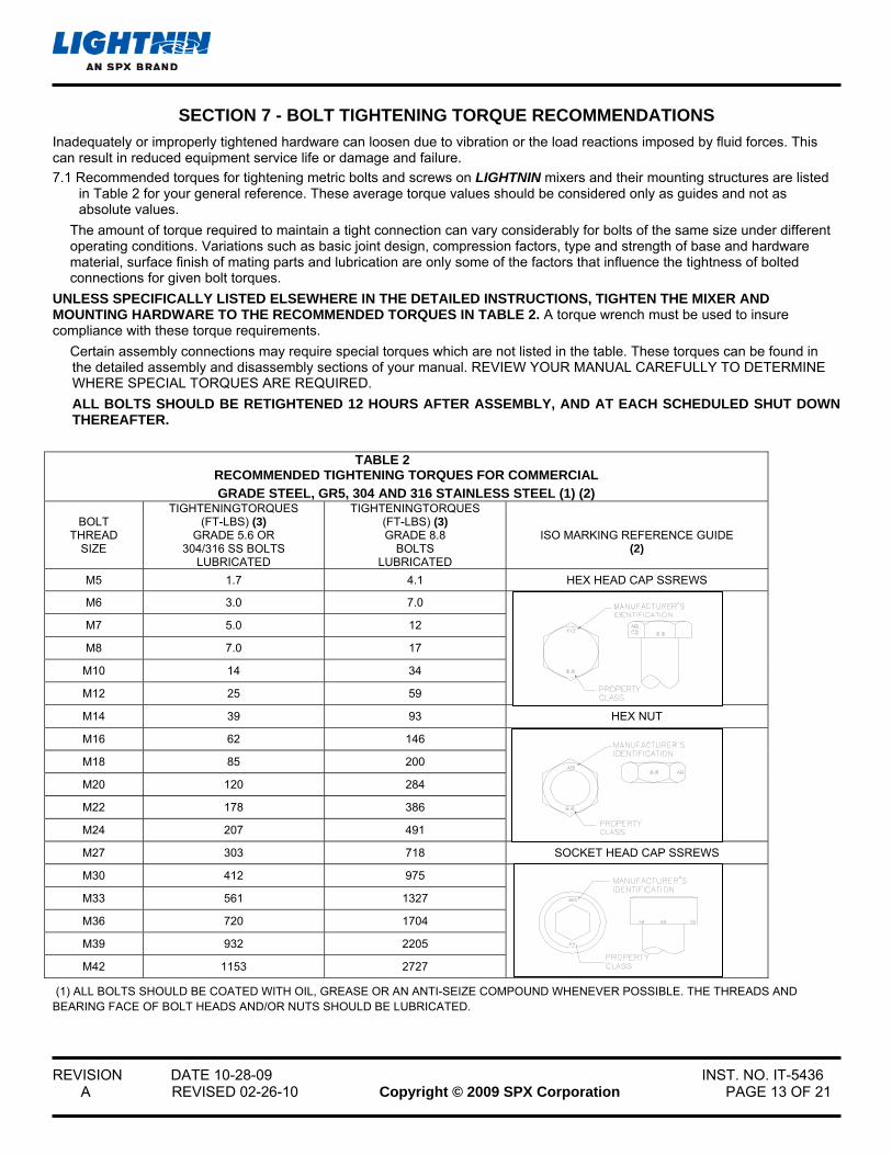
SECTION 7 - BOLT TIGHTENING TORQUE RECOMMENDATIONS
Inadequately or improperly tightened hardware can loosen due to vibration or the load reactions imposed by fluid forces. This can result in reduced equipment service life or damage and failure.
7.1 Recommended torques for tightening metric bolts and screws on LIGHTNIN mixers and their mounting structures are listed in Table 2 for your general reference. These average torque values should be considered only as guides and not as absolute values.
The amount of torque required to maintain a tight connection can vary considerably for bolts of the same size under different operating conditions. Variations such as basic joint design, compression factors, type and strength of base and hardware material, surface finish of mating parts and lubrication are only some of the factors that influence the tightness of bolted connections for given bolt torques.
UNLESS SPECIFICALLY LISTED ELSEWHERE IN THE DETAILED INSTRUCTIONS, TIGHTEN THE MIXER AND MOUNTING HARDWARE TO THE RECOMMENDED TORQUES IN TABLE 2. A torque wrench must be used to insure compliance with these torque requirements.
Certain assembly connections may require special torques which are not listed in the table. These torques can be found in the detailed assembly and disassembly sections of your manual. REVIEW YOUR MANUAL CAREFULLY TO DETERMINE WHERE SPECIAL TORQUES ARE REQUIRED.
ALL BOLTS SHOULD BE RETIGHTENED 12 HOURS AFTER ASSEMBLY, AND AT EACH SCHEDULED SHUT DOWN THEREAFTER.
TABLE 2
RECOMMENDED TIGHTENING TORQUES FOR COMMERCIAL GRADE STEEL, GR5, 304 AND 316 STAINLESS STEEL (1) (2)
BOLT
THREAD SIZE
TIGHTENINGTORQUES (FT-LBS) (3)
GRADE 5.6 OR 304/316 SS BOLTS
LUBRICATED
TIGHTENINGTORQUES (FT-LBS) (3) GRADE 8.8
BOLTS LUBRICATED
ISO MARKING REFERENCE GUIDE
(2)
M5 1.7 4.1 HEX HEAD CAP SSREWS
M6 3.0 7.0
M7 5.0 12
M8 7.0 17
M10 14 34
M12 25 59
M14 39 93 HEX NUT
M16 62 146
M18 85 200
M20 120 284
M22 178 386
M24 207 491
M27 303 718 SOCKET HEAD CAP SSREWS
M30 412 975
M33 561 1327
M36 720 1704
M39 932 2205
M42 1153 2727
(1) ALL BOLTS SHOULD BE COATED WITH OIL, GREASE OR AN ANTI-SEIZE COMPOUND WHENEVER POSSIBLE. THE THREADS AND BEARING FACE OF BOLT HEADS AND/OR NUTS SHOULD BE LUBRICATED.

REVISION DATE 10-28-09 INST. NO. IT-5436 A REVISED 02-26-10 Copyright © 2009 SPX Corporation PAGE 14 OF 21
(2) TORQUE VALUES SHOWN SUPERSEDE PREVIOUS TABLES THAT MAY HAVE ALLOWED LOWER VALUES. IT IS RECOMMENDED THAT ONLY FASTENERS BE USED THAT ARE PROPERLY MARKED, INCLUDING MANUFACTURER’S TRADE MARKING. ONLY FASTENERS MARKED AS SHOWN ARE GUARANTEED TO MEET SPECIFICATION AND PERFORMANCE REQUIREMENTS. (3) CONVERSION FACTORS: FRICTION LOCKING DEVICES MULTIPLY LUBRICATED VALUE BY 1.15. THESE TORQUES PERTAIN TO BOLTS OR NUTS WITH FRICTION LOCKING DEVICES SUCH AS NYLON PELLETS OR PATCHES, FIBER INSERTS OR UPSET THREADS. DRY VALUES MULTIPLY LUBRICATED VALUE BY 1.33.
METRIC VALUES IN N-m 1FT-LB = 1.3558 N-m
SECTION 8 - LUBRICATION
8.1 Your LIGHTNIN mixer has been lubricated at the factory with the correct type and amount of high quality lubricants. Lubricant cleanliness is protected by properly designed closures.
8.2 All mixer bearings are sealed type and are pre-packed with lubricant. Relubrication of these bearings is not necessary.
8.3 The gear chamber in LIGHTNIN Mi5(P,Q,L, or S) & Mi6(P,Q,L, or S) Series mixers has been factory filled with a grease suitable for ambient temperature ranges of -4 F to +122 F (-20 C to +50 C). Under normal operating conditions, this lubricant need not be changed until the unit has been dismantled for some reason. Refer to Table 3 for lubricant specifications.
8.4 Under adverse operating conditions, periodic changes of lubricant may be necessary. Adverse conditions are defined as operating in very humid, dust laden, chemical atmospheres, or where wide variations in ambient temperatures occur. Such adverse conditions can lead to deterioration of lubricant compounds and additives, and it is recommended that the condition of the grease be checked within six months of start-up.
Refer to Section 10 for instructions on disassembling the gear drive.
NOTE: THE GEAR CHAMBER SHOULD BE FILLED PER TABLE 3 CAPACITIES. ALL SEALING SURFACES SHOULD BE CLEANED AND NEW GASKET ELIMINATOR APPLIED. LOCTITE GASKET ELIMINATOR 504 SEALANT IS RECOMMENDED BY THE FACTORY.
RECOMMENDED GREASE GREASE
CAPACITY MODELS STANDARD FOOD GRADE LBS. kg
Mi5 & Mi6 (P,Q,L,S) 1 & 8 .9 .4
Mi5 & Mi6 (P,Q,L,S) 2 – 7 & 9 - 10 LIGHTNIN
SHC 0 BEL-RAY NO-TOX
HD 0 1.6 .7
TABLE 3
LIGHTNIN STANDARD GREASE (PART NUMBER 293101PSP – 2 LB. CONTAINER) AND FOOD GRADE GREASE (PART NUMBER 275255PSP – 14 OZ. TUBE) ARE AVAILABLE.
REVISION DATE 10-28-09 INST. NO. IT-5436 A REVISED 02-26-10 Copyright © 2009 SPX Corporation PAGE 15 OF 21
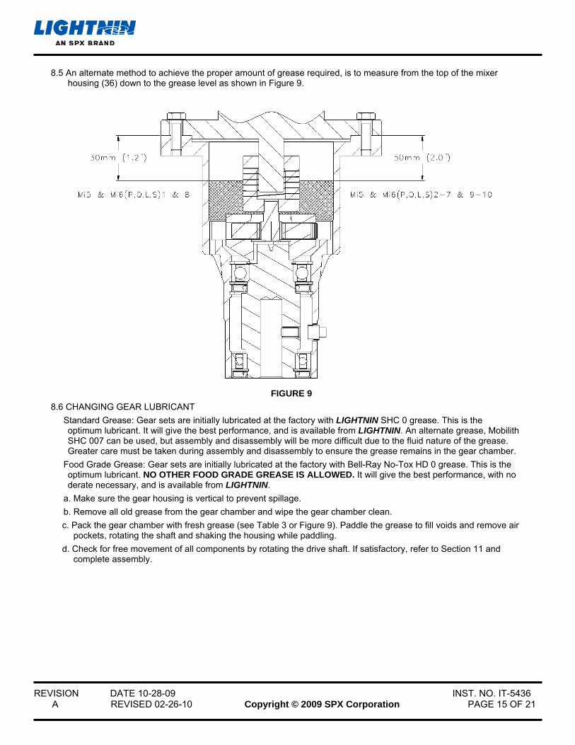
8.5 An alternate method to achieve the proper amount of grease required, is to measure from the top of the mixer housing (36) down to the grease level as shown in Figure 9.
FIGURE 9
8.6 CHANGING GEAR LUBRICANT
Standard Grease: Gear sets are initially lubricated at the factory with LIGHTNIN SHC 0 grease. This is the optimum lubricant. It will give the best performance, and is available from LIGHTNIN. An alternate grease, Mobilith SHC 007 can be used, but assembly and disassembly will be more difficult due to the fluid nature of the grease. Greater care must be taken during assembly and disassembly to ensure the grease remains in the gear chamber.
Food Grade Grease: Gear sets are initially lubricated at the factory with Bell-Ray No-Tox HD 0 grease. This is the optimum lubricant. NO OTHER FOOD GRADE GREASE IS ALLOWED. It will give the best performance, with no derate necessary, and is available from LIGHTNIN.
a. Make sure the gear housing is vertical to prevent spillage.
b. Remove all old grease from the gear chamber and wipe the gear chamber clean.
c. Pack the gear chamber with fresh grease (see Table 3 or Figure 9). Paddle the grease to fill voids and remove air pockets, rotating the shaft and shaking the housing while paddling.
d. Check for free movement of all components by rotating the drive shaft. If satisfactory, refer to Section 11 and complete assembly.
REVISION DATE 10-28-09 INST. NO. IT-5436 A REVISED 02-26-10 Copyright © 2009 SPX Corporation PAGE 16 OF 21
SECTION 9 - PREPARATION FOR DISASSEMBLY AND ASSEMBLY WARNING: DISCONNECT MOTOR LEADS OR OTHERWISE LOCK-OUT POWER SUPPLY BEFORE SERVICING THIS MIXER. EYE PROTECTION MUST BE WORN.
9.1 GENERAL - LIGHTNIN mixers are precision manufactured and assembled to provide long, trouble free service
when properly maintained. If it becomes necessary to disassemble the unit, careful, precise reassembly is necessary.
Refer to the assembly drawing for location of parts. Equipment that will be required to service the mixer, in addition to standard mechanics tools, is a rubber mallet, retaining ring pliers, arbor press and torque wrench.
When disassembling the mixer, clean adjacent external surfaces to prevent dirt from entering the housings.
It is recommended that oil seals be replaced and gasket eliminator sealer be reapplied when the mixer is disassembled.
9.2 SEAL REPLACEMENT
New oil seals should always be used. Drive out all old oil seals and remove accumulations of sealing compound. When replacing seals:
a. Coat the lips of seals with bearing grease.
b. Install oil seals with the lip facing in the direction indicated on the assembly drawing.
c. Coat the section of the shaft sealing surface with oil. If the oil seal must pass over a keyway, wrap the shaft with thin paper or tape, coat with grease, and pass the seal over.
9.3 BEARING REPLACEMENT
Inspect the bearings carefully and replace if necessary.
a. Old bearings can be removed with a puller or an arbor press.
b. New bearings can be pressed onto the shafts. Be careful to apply load only to the inner race.
c. Make sure the bearings are tightly seated against the shaft or housing shoulder with no clearance.
SECTION 10 - DISASSEMBLY AND ASSEMBLY OF DIRECT DRIVE UNITS DISASSEMBLY:
10.1 MOTOR REMOVAL
Models: Mi1(P,Q,L)1, 2, 3, 4 ,5 ,6 ,8, 9 & 10
a. Remove set screw access plug (97) from the mixer housing (36).
b. Remove the impeller shaft (42) from the drive quill (35), by loosening the set screw (96) enough to release the impeller shaft. The impeller shaft is now free from the chuck and can be removed.
Models: Mi1(Q,L)7
c. Disconnect and remove the impeller shaft (42) from the rigid upper shaft (40) by removing hex head cap screws (67) and hex nuts (69).
d. Remove set screw access plugs (97) from the mixer housing (36).
e. Loosen the first two set screws (96) enough to clear the rigid upper shaft (40). Rotate the rigid upper shaft (40) to access the second two set screws. While holding the upper shaft (40), loosen the set screws and remove the rigid upper shaft (40).
“P” Units: Turn the clamp screw counterclockwise to loosen the clamp assembly (116). Remove the mixer from the tank. Remove the yoke / clamp assembly (114 / 115), from the housing (36) by removing the two hex head cap screws 113).
“Q” & “L” Units: Hold the two hex head cap screws (110) and loosen the two hex nuts (109). Remove the mixer from the pedestal (111).

REVISION DATE 10-28-09 INST. NO. IT-5436 A REVISED 02-26-10 Copyright © 2009 SPX Corporation PAGE 17 OF 21
“S” Units: Hold the four hex head cap screws (110) and loosen the four hex nuts (109). Remove the mixer from the pedestal (111).
f. Set the mixer upright on a workbench.
g. Remove the four hex head cap screws (160), (or four nuts 161 on D70 and D90 motors) holding the motor (101) to the housing (36).
h. Separate and remove the motor (101) from the housing (36). One half of the motor coupling half (150) will remain attached to the motor shaft.
i. Loosen the set screw, and remove the motor coupling half (150) and key (106).
j. Loosen the set screw, remove the quill shaft coupling half, and coupling insert.
10.2 QUILL SHAFT & HOUSING DISASSEMBLY
a. Place the housing (36) upright on a workbench and remove the retaining rings (44 & 56).
b. Place the housing upright in a press, and press out the quill shaft (35), bearing (41) and oil seal (49).
c. Press the lower bearing (41) off the shaft.
d. Turn the housing over and press out the upper bearing (37).
e. Remove lower retaining ring (44), only if necessary.
f. Inspect the bearings (37 & 41). Replace if there is excessive wear.
ASSEMBLY:
10.3 PREPARING FOR ASSEMBLY a. Clean all parts thoroughly. b. Inspect for the following defects:
1. Cracks or damage of the housing. 2. Dents, gouges or scoring of the drive shaft, housing bore, and particularly the mating faces of the motor and
housing.
c. Repair or replace defective parts. It is good practice to replace an oil seal which has been removed from the housing. Apply a small quantity of bearing grease to the housing bore, and around the oil seal lip to provide lubrication and make the seal more effective.
d. Replace the bearings if they show indications of wear.
10.4 QUILL SHAFT ASSEMBLY
a. Press the lower bearing (41) onto the quill shaft (35). The bearing must seat against the shoulder with no visible gap.
10.5 QUILL SHAFT AND HOUSING ASSEMBLY
a. Install the lower retaining ring (44), if removed, in the housing (36).
b. Mount the housing (36) in an arbor press, large end up.
c. Press the bearing (37) on its outer race to seat against retaining ring (44).
d. Install the upper retaining ring (44).
e. Support the housing, large end down, by resting the inner race of the bearing on a suitable sleeve.
f. Press the quill shaft (35) into the bearing until the shoulder of the shaft registers against the inner race of the bearing.
g. Install the upper retaining ring (56) in the shaft groove.
h. Turn the housing large end down, and press the lower oil seal (49) until it is flush with the end of the housing.
10.6 MOTOR COUPLING ASSEMBLY
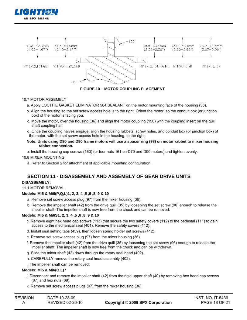
a. Position the motor coupling hub (150) as shown in Figure 10.
b. Tighten the set screws.
c. Place the drive coupling half and key onto the end of the quill shaft. The drive coupling half on the quill on Models Mi1(P,Q,L) 1, 4, 5, 7, 8 & 10 are seated directly against the shaft shoulder. Model Mi1(P,Q,L) 6 is set 3mm (.12”) and model Mi1(P,Q,L) 7 4.5mm (.18”) off the shoulder. Tighten the set screw.
d. Install the coupling insert into the quill shaft coupling half.
REVISION DATE 10-28-09 INST. NO. IT-5436 A REVISED 02-26-10 Copyright © 2009 SPX Corporation PAGE 18 OF 21
FIGURE 10 – MOTOR COUPLING PLACEMENT
10.7 MOTOR ASSEMBLY
a. Apply LOCTITE GASKET ELIMINATOR 504 SEALANT on the motor mounting face of the housing (36).
b. Align the housing so the set screw access hole is to the right. Orient the motor, so the conduit box (or junction box) of the motor is facing you.
c. Move the motor, over the housing (36) and align the motor coupling (150) with the coupling insert on the quill shaft coupling half.
d. Once the coupling halves engage, align the housing rabbets, screw holes, and conduit box (or junction box) of the motor, with the set screw access hole in the housing, to the right.
Note: Units using D80 and D90 frame motors will use a spacer ring (98) on motor rabbet to mixer housing rabbet connection.
e. Install the housing cap screws (160) (or four nuts 161 on D70 and D90 motors) and tighten evenly.
10.8 MIXER MOUNTING
a. Refer to Section 2 for attachment of applicable mounting configuration.
SECTION 11 - DISASSEMBLY AND ASSEMBLY OF GEAR DRIVE UNITS DISASSEMBLY:
11.1 MOTOR REMOVAL
Models: Mi5 & Mi6(P,Q,L)1, 2, 3, 4 ,5 ,6 ,8, 9 & 10
a. Remove set screw access plug (97) from the mixer housing (36).
b. Remove the impeller shaft (42) from the drive quill (35) by loosening the set screw (96) enough to release the impeller shaft. The impeller shaft is now free from the chuck and can be removed.
Models: Mi5 & Mi6S1, 2, 3, 4 ,5 ,6 ,8, 9 & 10
c. Remove eight hex head cap screws (113) that secure the two safety covers (112) to the pedestal (111) to gain access to the mechanical seal (401). Remove the safety covers (112).
d. Install seal setting tabs (459), then loosen spring holder set screws (412).
e. Remove set screw access plug (97) from the mixer housing (36).
f. Remove the impeller shaft (42) from the drive quill (35) by loosening the set screw (96) enough to release the impeller shaft. The impeller shaft is now free from the chuck and can be withdrawn.
g. Slide the mixer shaft (42) down through the rotary seal head (402).
h. CAREFULLY remove the rotary seal head assembly (402).
i. The impeller shaft can be removed.
Models: Mi5 & Mi6(Q,L)7
j. Disconnect and remove the impeller shaft (42) from the rigid upper shaft (40) by removing hex head cap screws (67) and hex nuts (69).
k. Remove set screw access plugs (97) from the mixer housing (36).
REVISION DATE 10-28-09 INST. NO. IT-5436 A REVISED 02-26-10 Copyright © 2009 SPX Corporation PAGE 19 OF 21
l. Loosen the first two set screws (96) enough to clear the rigid upper shaft (40). Rotate the rigid upper shaft (40) to access the second two set screws. While holding the upper shaft (40), loosen the set screws and remove the rigid upper shaft (40).
Models: Mi5 & Mi6S7
m. Disconnect and remove the impeller shaft (42) from the rigid upper shaft (40) by removing hex head cap screws (67) and hex nuts (69).
n. Remove eight hex head cap screws (113) that secure the two safety covers (112) to the pedestal (111) to gain access to the mechanical seal (401). Remove the safety covers (112).
o. Install seal setting tabs (459), then loosen spring holder set screws (412).
p. Remove set screw access plugs (97) from the mixer housing (36).
q. Loosen the first two set screws (96) enough to clear the rigid upper shaft (40). Rotate the rigid upper shaft (40) to access the second two set screws. While holding the upper shaft (40), loosen the set screws.
r. Slide the rigid upper shaft (40) down through the rotary seal head (402).
s. CAREFULLY remove the rotary seal head assembly (402).
t. The rigid upper shaft (40) can be removed.
“P” Units: Turn the clamp screw counterclockwise to loosen the clamp assembly (116). Remove the mixer from the tank. Remove the yoke / clamp assembly (114 / 115), from the housing (36) by removing the two hex head cap screws 113).
“Q” & “L” Units: Hold the two hex head cap screws (110) and loosen the two hex nuts (109). Remove the mixer from the pedestal (111).
“S” Units: Hold the four hex head cap screws (110) and loosen the four hex nuts (109). Remove the mixer from the pedestal (111).
u. Set the mixer upright on a workbench.
v. Remove the four hex head cap screws (160) (or four nuts 161 on D70 and D90 motors) holding the motor (101) to the mixer housing (36).
w. Separate and remove the motor (101) from the mixer housing (36). The helical coupling (150) and sun gear will remain attached to the motor shaft.
x. Move the mixer housing over a suitable container, remove the old lubricant and dispose of properly.
y. Remove the sun gear (9) and motor coupling (150).
z. Remove the gear carrier assembly (1), retaining ring (7), ring gear (2), four dowel pins (5) and any remaining old lubricant.
11.2 QUILL SHAFT & HOUSING DISASSEMBLY
a. Place the housing (36) upright on a workbench and remove the retaining rings (44 & 56).
b. Place the housing upright in a press, and press out the quill shaft (35), bearing (41) and oil seal (49).
c. Press the lower bearing (41) off the shaft.
d. Turn the housing over and press out the upper bearing (37).
e. Turn the housing over, remove middle retaining ring (44).
f. Turn the housing over and press the oil seal (38), from the housing (36).
g. Inspect the bearings (37 & 41). Replace if there is excessive wear.
ASSEMBLY:
11.3 PREPARING FOR ASSEMBLY
a. Clean all parts thoroughly.
b. Inspect for the following defects:
1. Cracks or damage of the housing.
2. Dents, gouges or scoring of the quill shaft, housing bore, and particularly the mating faces of the motor and housing.

REVISION DATE 10-28-09 INST. NO. IT-5436 A REVISED 02-26-10 Copyright © 2009 SPX Corporation PAGE 20 OF 21
c. Repair or replace defective parts. It is good practice to replace an oil seal which has been removed from the housing. Apply a small quantity of bearing grease to the housing bore, and around the oil seal lip to provide lubrication and make the seal more effective.
d. Replace the bearings if they show indications of wear.
11.4 QUILL SHAFT ASSEMBLY
a. Press the lower bearing (41) onto the quill shaft (35). The bearing must seat against the shoulder with no visible gap.
11.5 QUILL SHAFT AND HOUSING ASSEMBLY
a. Install the lower retaining ring (44) in the housing (36).
b. Mount the housing (36) in an arbor press, large end up.
c. Press the oil upper seal (38) into the housing (36) with the seal cavity facing the large end of the housing.
d. Install the middle retaining ring (44) in the housing (36).
e. Press the bearing (37) on its outer race to seat against the middle retaining ring (44).
f. Install the upper retaining ring (44).
g. Support the housing, large end down, by resting the inner race of the bearing on a suitable sleeve.
h. Press the quill shaft (35) into the bearing until the shoulder of the shaft registers against the inner race of the bearing.
i. Install the upper retaining ring (56) in the shaft groove. j. Turn the housing large end down, and press the lower oil seal (49) until it is flush with the end of the housing.
11.6 GEAR ASSEMBLY
a. Install the ring gear retaining pins (5).
b. Install the ring gear (2) in the bearing housing (36).
c. Install the retaining ring (7) in the groove above the ring gear.
d. PACK THE GEAR CARRIER (1) WITH GREASE and rotate the gears several times to distribute the grease to the needle bearings (13). Refer to Section 6 of these instructions for lubricant recommendations.
e. Models Mi5 & Mi6 (P,Q,L,S) 1, 2, 3, 4, 5, 8 & 9: Align the flats on the inside of the gear carrier (1) with the flats on the quill shaft (35).
f. Models Mi5 & Mi6 (P,Q,L,S) 6, 7 &10: Install the key (27) in the quill shaft (35). Align the keyway in the gear carrier (1) with the keyway on the quill shaft (35).
g. Place the gear carrier assembly onto the quill shaft.
REVISION DATE 10-28-09 INST. NO. IT-5436 A REVISED 02-26-10 Copyright © 2009 SPX Corporation PAGE 21 OF 21
11.7 MOTOR COUPLING ASSEMBLY
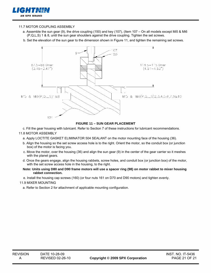
a. Assemble the sun gear (9), the drive coupling (150) and key (107), (Item 107 – On all models except Mi5 & Mi6 (P,Q,L,S) 1 & 8, until the sun gear shoulders against the drive coupling. Tighten the set screws.
b. Set the elevation of the sun gear to the dimension shown in Figure 11, and tighten the remaining set screws.
FIGURE 11 – SUN GEAR PLACEMEMT
c. Fill the gear housing with lubricant. Refer to Section 7 of these instructions for lubricant recommendations.
11.8 MOTOR ASSEMBLY
a. Apply LOCTITE GASKET ELIMINATOR 504 SEALANT on the motor mounting face of the housing (36).
b. Align the housing so the set screw access hole is to the right. Orient the motor, so the conduit box (or junction box) of the motor is facing you.
c. Move the motor, over the housing (36) and align the sun gear (9) in the center of the gear carrier so it meshes with the planet gears.
d. Once the gears engage, align the housing rabbets, screw holes, and conduit box (or junction box) of the motor, with the set screw access hole in the housing, to the right.
Note: Units using D80 and D90 frame motors will use a spacer ring (98) on motor rabbet to mixer housing rabbet connection.
e. Install the housing cap screws (160) (or four nuts 161 on D70 and D90 motors) and tighten evenly.
11.9 MIXER MOUNTING
a. Refer to Section 2 for attachment of applicable mounting configuration.