Embed Size (px)
Citation preview
VACUUM
TECHNOLOGY
OPERATING AND MAINT ENANCE INSTRUCTIONS
(Translation of the original instructions)
OIL FREE VANE COMPRESSORS
SC.5-COMPRESSOR SC.8-COMPRESSOR SB.16-COMPRESSOR SB.25-COMPRESSOR SB.40-COMPRESSOR
CB.6 CB.10 CB.12 CB.16-1
CC.60-1 CC.80-1 CC.100-1 CC.140-1

User and maintenance manual EN
SC.5-COMPRESSOR – CB.6 – SC.8-COMPRESSOR – CB.10 – CB.12 – SB.16-COMPRESSOR – CB.16-1 – SB.25-COMPRESSOR – SB.40-COMPRESSOR – CC.60-1 – CC.80-1 – CC.100-1 – CC.140-1
1
8702039 – 25/01/2017 – R.6 www.dvp.it
INDEX
1 INTRODUCTION .................................................................................................................................................... 2
1.1 GENERAL INFORMATION .............................................................................................................................. 2 1.2 MANUFACTURER INFORMATION ................................................................................................................. 2 1.3 METHOD OF CONSULTATION ...................................................................................................................... 2 1.4 PERSONNEL QUALIFICATIONS .................................................................................................................... 2 1.5 PERSONAL PROTECTION EQUIPMENT....................................................................................................... 2 1.6 IDENTIFICATION PLATE ................................................................................................................................ 3
2 SAFETY ................................................................................................................................................................. 3
2.1 GENERAL WARNINGS ................................................................................................................................... 3 2.2 RESIDUAL RISKS ........................................................................................................................................... 3 2.3 PICTOGRAMS ................................................................................................................................................. 4
3 COMPRESSOR DESCRIPTION ............................................................................................................................ 5
3.1 INTENTED USE AND CONTRAINDICATIONS ............................................................................................... 5 3.1.1 INTENTED USE ........................................................................................................................................ 5 3.1.2 CONTRAINDICATIONS ............................................................................................................................ 5
3.2 NOISE EMISSIONS ......................................................................................................................................... 5 3.3 DIMENSIONS AND CHARACTERISTICS ....................................................................................................... 6
3.3.1 Model: SC.5-COMPRESSOR .................................................................................................................. 6 3.3.2 Model: CB.6 .............................................................................................................................................. 7 3.3.3 Model: SC.8-COMPRESSOR .................................................................................................................. 8 3.3.4 Model: CB.10 – CB.12 .............................................................................................................................. 9 3.3.5 Model: CB.16-1....................................................................................................................................... 10 3.3.6 Model: SB.16-COMPRESSOR – SB.25-COMPRESSOR – SB.40-COMPRESSOR ............................. 11 3.3.7 Model: CC.60-1 – CC.80-1 – CC.100-1 – CC.140-1 .............................................................................. 12
4 INSTALLATION ................................................................................................................................................... 13
4.1 RECEIPT AND CONTENT VERIFICATION .................................................................................................. 13 4.2 PACKAGING .................................................................................................................................................. 13 4.3 TRANSPORT AND HANDLING ..................................................................................................................... 13 4.4 STORAGE ..................................................................................................................................................... 13 4.5 ENVIRONMENTAL CONDITIONS ................................................................................................................ 14 4.6 COMPRESSOR INSTALLATION .................................................................................................................. 14 4.7 MOTOR INSTALLATION (ONLY CC.60-1 – CC.80-1 – CC.100-1 – CC.140-1) ............................................ 14 4.8 USER SYSTEM ............................................................................................................................................. 15 4.9 CONNECTION ............................................................................................................................................... 15
4.9.1 OUTLET AND INTAKE CONNECTION .................................................................................................. 15 4.9.2 WIRING ................................................................................................................................................... 15
5 OPERATING INSTRUCTIONS ............................................................................................................................ 16
5.1 OPERATION .................................................................................................................................................. 16 5.1.1 START-UP .............................................................................................................................................. 16 5.1.2 STOP ....................................................................................................................................................... 16
6 MAINTENANCE ................................................................................................................................................... 17
6.1 GENERAL WARNINGS ................................................................................................................................. 17 6.2 MAINTENANCE TABLE................................................................................................................................. 17
6.2.1 CLEANING THE MOTOR FAN GUARD AND COMPRESSOR ............................................................. 17 6.2.2 REPLACING THE INTAKE FILTER ........................................................................................................ 17 6.2.3 REPLACING THE VANES ...................................................................................................................... 17
6.3 SPARE PARTS AND ACCESSORIES ........................................................................................................... 18
7 HOW TO RETURN THE PRODUCT ................................................................................................................... 19
8 DISMANTLING .................................................................................................................................................... 19
9 TROUBLESHOOTING ......................................................................................................................................... 20

User and maintenance manual EN
SC.5-COMPRESSOR – CB.6 – SC.8-COMPRESSOR – CB.10 – CB.12 – SB.16-COMPRESSOR – CB.16-1 – SB.25-COMPRESSOR – SB.40-COMPRESSOR – CC.60-1 – CC.80-1 – CC.100-1 – CC.140-1
2
8702039 – 25/01/2017 – R.6 www.dvp.it
1 INTRODUCTION
1.1 GENERAL INFORMATION This manual is meant to provide you with important information for the safety of persons involved in the use and maintenance of the compressor. This manual, originally written in ITALIAN, is an integral part of the compressor and must be preserved with care for the entire working life of the compressor and in the event of sale, lease or loaned use of the compressor, it must be delivered to the new user along with the EC declaration of conformity. Carrying out any operations on the compressor before reading and fully understanding all the instructions in this manual is prohibited. The images contained in this document are examples only and are not binding for the Manufacturer. The Manufacturer reserves the right to make changes to components, make product improvements or for any other reason without updating this manual, if said components or parts do not alter the compressor's operation and safety.
1.2 MANUFACTURER INFORMATION
D.V.P. Vacuum Technology s.p.a. Via Rubizzano, 627
40018 - S. Pietro in Casale (BO) - ITALY
Ph +3905118897101 Fx +3905118897170
e-mail: [email protected] web site: http://www.dvp.it
Please always include the following information in all communications regarding the compressor:
• Compressor model and serial number;
• year of manufacture;
• date of purchase;
• detailed information regarding problems occurred.
1.3 METHOD OF CONSULTATION For improved understanding of the information provided in this manual, warnings or instructions considered critical or hazardous are marked with the following symbols:
HAZARD
Failure to comply with these instructions may cause hazards to persons.
WARNING
Failure to comply with these instructions may cause damage to the compressor.
1.4 PERSONNEL QUALIFICATIONS To ensure that all operations performed on the compressor are carried out safely, operators must have the qualifications and requirements to carry out these operations. Operators are classified as follows:
FIRST LEVEL OPERATOR: Unqualified personnel, without specific skills and able to perform simple tasks only.
MECHANICAL MAINTENANCE OPERATOR: Technician qualified to work on mechanical parts to carry out any necessary adjustments, maintenance operations or repairs. Not qualified to work on electrical systems in presence of voltage.
ELECTRICAL MAINTENANCE OPERATOR: Technician in charge of all operations of electrical nature. He can operate in the presence of voltage inside cabinets and connector boxes.
1.5 PERSONAL PROTECTION EQUIPMENT This manual assumes that the compressor has been installed in workplaces complying with all mandatory safety requirements; in particular, it is mandatory that personnel is equipped with personal protective equipment in relation to the activities that must be performed.
User and maintenance manual EN
SC.5-COMPRESSOR – CB.6 – SC.8-COMPRESSOR – CB.10 – CB.12 – SB.16-COMPRESSOR – CB.16-1 – SB.25-COMPRESSOR – SB.40-COMPRESSOR – CC.60-1 – CC.80-1 – CC.100-1 – CC.140-1
3
8702039 – 25/01/2017 – R.6 www.dvp.it
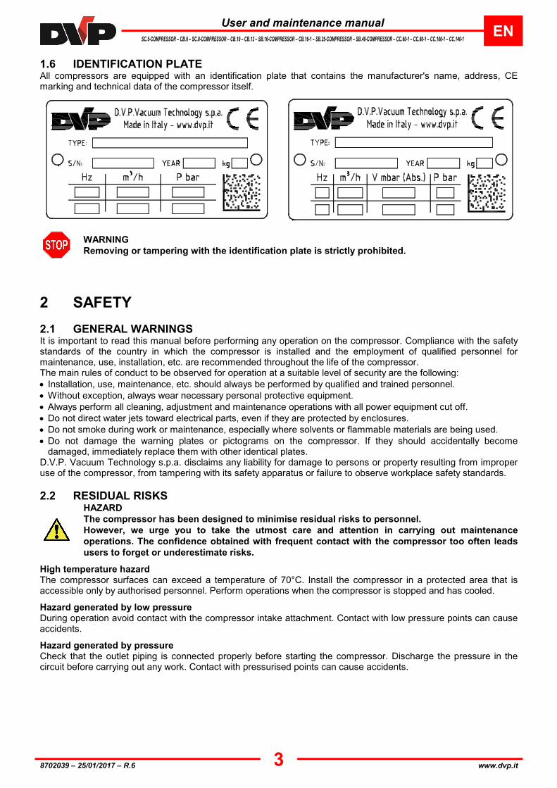
1.6 IDENTIFICATION PLATE All compressors are equipped with an identification plate that contains the manufacturer's name, address, CE marking and technical data of the compressor itself.
WARNING
Removing or tampering with the identification plate is strictly prohibited.
2 SAFETY
2.1 GENERAL WARNINGS It is important to read this manual before performing any operation on the compressor. Compliance with the safety standards of the country in which the compressor is installed and the employment of qualified personnel for maintenance, use, installation, etc. are recommended throughout the life of the compressor. The main rules of conduct to be observed for operation at a suitable level of security are the following:
• Installation, use, maintenance, etc. should always be performed by qualified and trained personnel.
• Without exception, always wear necessary personal protective equipment.
• Always perform all cleaning, adjustment and maintenance operations with all power equipment cut off.
• Do not direct water jets toward electrical parts, even if they are protected by enclosures.
• Do not smoke during work or maintenance, especially where solvents or flammable materials are being used.
• Do not damage the warning plates or pictograms on the compressor. If they should accidentally become damaged, immediately replace them with other identical plates.
D.V.P. Vacuum Technology s.p.a. disclaims any liability for damage to persons or property resulting from improper use of the compressor, from tampering with its safety apparatus or failure to observe workplace safety standards.
2.2 RESIDUAL RISKS
HAZARD
The compressor has been designed to minimise residual risks to personnel.
However, we urge you to take the utmost care and attention in carrying out maintenance
operations. The confidence obtained with frequent contact with the compressor too often leads
users to forget or underestimate risks.
High temperature hazard The compressor surfaces can exceed a temperature of 70°C. Install the compressor in a protected area that is accessible only by authorised personnel. Perform operations when the compressor is stopped and has cooled.
Hazard generated by low pressure During operation avoid contact with the compressor intake attachment. Contact with low pressure points can cause accidents.
Hazard generated by pressure Check that the outlet piping is connected properly before starting the compressor. Discharge the pressure in the circuit before carrying out any work. Contact with pressurised points can cause accidents.

User and maintenance manual EN
SC.5-COMPRESSOR – CB.6 – SC.8-COMPRESSOR – CB.10 – CB.12 – SB.16-COMPRESSOR – CB.16-1 – SB.25-COMPRESSOR – SB.40-COMPRESSOR – CC.60-1 – CC.80-1 – CC.100-1 – CC.140-1
4
8702039 – 25/01/2017 – R.6 www.dvp.it
Danger from the emission of harmful substances Air released from the compressor outlet contains traces of graphite powder due to the wear of the vanes; ensure compatibility with the system and the working environment. A failure or the wear of the plant circuit connected to the compressor outlet may cause the emission of graphite powder into the atmosphere; avoid dispersion in the environment and contamination of other materials. Whenever air containing hazardous substances is sucked in (i.e. biological or microbiological agents), use abatement systems located in front of the compressor intake.
Electrical hazard Electrical equipment in the compressor includes live parts which, upon contact, can cause serious damage to persons and property. Any kind of intervention on the electrical system must be performed by qualified personnel.
Fire hazard Use of the compressor for any uses not provided for or prohibited by this manual as well as a lack of proper maintenance can cause malfunction with a risk of overheating and fire. In case of fire, do not use water to extinguish the flames, but use dry extinguisher or CO2 or other means compatible with the presence of electrical equipment.
Entanglement hazard There is a permanent impending hazard of entangling or entrapping hair and clothing in the cooler fan inside the guard near the fan casing on the electric motor. Tie long hair up and do not wear baggy clothing, long laces or other items that could get caught up.
Part projection hazard Install the pump in order to avoid those in charge of works being directly hit by parts or bits of parts flying through the fan cover casing due to the cooling fan breaking.
2.3 PICTOGRAMS Pictograms with warning and safety symbols for operators' safety have been applied to the compressor. Read carefully and take note of the symbols and their messages before using the compressor.
ELECTRICAL HAZARD
The compressor is located near electrical connections (protected), however accidental contact
can cause electric shock and death.
HOT SURFACE HAZARD
The compressor is located close to surfaces with temperatures exceeding 70°C which may lead
to burns of medium severity.
DO NOT USE OIL
Warning! This is a dry running pump. Do not use any lubricant or oil.
REFER TO INSTRUCTION MANUAL/BOOKLET
Before use read the instructions in the operating manual.
D.V.P. Vacuum Technology s.p.a. disclaims any liability for damage to persons or property due to non-compliance with the instructions indicated in pictograms or their improper preservation.

User and maintenance manual EN
SC.5-COMPRESSOR – CB.6 – SC.8-COMPRESSOR – CB.10 – CB.12 – SB.16-COMPRESSOR – CB.16-1 – SB.25-COMPRESSOR – SB.40-COMPRESSOR – CC.60-1 – CC.80-1 – CC.100-1 – CC.140-1
5
8702039 – 25/01/2017 – R.6 www.dvp.it
3 COMPRESSOR DESCRIPTION
3.1 INTENTED USE AND CONTRAINDICATIONS 3.1.1 INTENTED USE The compressor described in this manual is of the oil-free rotary vane type. This compressor has been specifically designed to work with dry, clean air and inert gas, the suction temperature of which must be between 0°C and 40°C. Any other use is prohibited. The Manufacturer is not liable for any damage to persons and/or property caused by improper use or not allowed use of the compressor. 3.1.2 CONTRAINDICATIONS
Any use other than that for which the compressor was constructed is to be considered
an abnormal condition and therefore can cause damage to the compressor and pose a
serious danger to the operator. Below is a series of operations involving improper use of the compressor, which are not permitted under any circumstances.
• Do not use the compressor in an explosive or aggressive atmosphere or in an atmosphere with a high concentration of dust or oily substances in the air and do not use the compressor to pump explosive, flammable or corrosive gases or gases that form particles. Using the compressor in these atmospheres and with these types of gases can cause injury, explosion, fire or serious damage to the compressor itself.
• Do not use non-original spare parts or parts not provided by the manufacturer;
• Do not use the unit to pump solid materials, chemicals, powders, solvents or other substances differing from those permitted. These types of materials may damage the unit, degrade its performance or reduce its working life;
• Do not expose the compressor to rain, steam or excessive humidity;
• Do not place or store near or in proximity of flammable or combustible materials or substances;
3.2 NOISE EMISSIONS The compressor has been designed and constructed to reduce noise at its source. The sound pressure values indicated in point 3.3 (Sizes and Specifications) of this manual have been read in compliance with directive UNI EN ISO 2151 making the compressor work at 2/3 of the acceptable maximum pressure with intake and outlet conveyed. The actual noise emission while operating depends, however, on the installation conditions and position of the compressor on the system.

User and maintenance manual EN
SC.5-COMPRESSOR – CB.6 – SC.8-COMPRESSOR – CB.10 – CB.12 – SB.16-COMPRESSOR – CB.16-1 – SB.25-COMPRESSOR – SB.40-COMPRESSOR – CC.60-1 – CC.80-1 – CC.100-1 – CC.140-1
6
8702039 – 25/01/2017 – R.6 www.dvp.it
3.3 DIMENSIONS AND CHARACTERISTICS
3.3.1 Model: SC.5-COMPRESSOR
B
A
A Intake 2 Terminal board 5 Motor rating plate
B Outlet 3 Information plate
1 Motor fan guard 4 Attachment point
TECHNICAL SPECIFICATIONS SC.5
50 Hz 60 Hz
Inlet capacity m³/h 5 6
Final pressure (Abs.) mbar - hPa 120 **
Maximum over pressure bar - 105Pa 0,8
Motor power kW (1~ / 3~) 0,12 / 0,12 0,15 / 0,15
Nominal r.p.m. n/min 2800 3300
Noise level (UNI EN ISO 2151) (K 3dB) (Used as a pump) dB(A) 59 ** 61 **
Noise level (UNI EN ISO 2151) (K 3dB) (Used as a compressor) dB(A) 62 64
Weight kg (1~ / 3~) 5,4 / 5,4
Intake pump Ø9mm (1/8″G)
Outlet pump 1/8″G
Operating temperature (room temp. 20°C) °C 65 ÷ 70 70 ÷ 75
Required room temp. for place of installation °C 0 ÷ 40
Ambient temperature for storage/transport °C -20 ÷ 50
MAX humidity / altitude 80% / 1000m a.s.l. *
(*) Please contact the Manufacturer if environmental conditions are different from those prescribed. (**) For use as a pump consult manual code: 8702038..

User and maintenance manual EN
SC.5-COMPRESSOR – CB.6 – SC.8-COMPRESSOR – CB.10 – CB.12 – SB.16-COMPRESSOR – CB.16-1 – SB.25-COMPRESSOR – SB.40-COMPRESSOR – CC.60-1 – CC.80-1 – CC.100-1 – CC.140-1
7
8702039 – 25/01/2017 – R.6 www.dvp.it
3.3.2 Model: CB.6
A
B
A Intake 2 Attachment point 5 Terminal board
B Outlet 3 Motor rating plate
1 Motor fan guard 4 Information plate
TECHNICAL SPECIFICATIONS CB.6
50 Hz 60 Hz
Capacity m³/h 6 7
Maximum over pressure bar - 105Pa 0,8
Motor power kW (1~ / 3~) 0,25 / 0,25 0,30 / 0,30
Nominal r.p.m. n/min 2800 3300
Noise level (UNI EN ISO 2151) (K 3dB) dB(A) 60 62
Weight kg (1~ / 3~) 8,5 / 7,5
Compressor intake 1/4”G
Compressor outlet 1/2”G
Operating temperature (room temp. 20°C) °C 65 ÷ 70 70 ÷ 75
Required operating room temperature °C 0 ÷ 40
Storage/transport room temperature °C -20 ÷ 50
MAX humidity / altitude 80% / 1000m a.s.l. *
(*) Please contact the manufacturer if environmental conditions are different from those prescribed.

User and maintenance manual EN
SC.5-COMPRESSOR – CB.6 – SC.8-COMPRESSOR – CB.10 – CB.12 – SB.16-COMPRESSOR – CB.16-1 – SB.25-COMPRESSOR – SB.40-COMPRESSOR – CC.60-1 – CC.80-1 – CC.100-1 – CC.140-1
8
8702039 – 25/01/2017 – R.6 www.dvp.it
3.3.3 Model: SC.8-COMPRESSOR
B
C
D
A
A Intake D Optional outlet 3 Information plate
B Outlet 1 Motor fan guard 4 Attachment point
C Optional intake 2 Terminal board 5 Motor rating plate
TECHNICAL SPECIFICATIONS SC.8
50 Hz 60 Hz
Inlet capacity m³/h 8 9
Final pressure (Abs.) mbar - hPa 120 **
Maximum over pressure bar - 105Pa 0,8
Motor power kW (1~ / 3~) 0,25 / 0,25 0,30 / 0,30
Nominal r.p.m. n/min 2800 3300
Noise level (UNI EN ISO 2151) (K 3dB) (Used as a pump) dB(A) 59 ** 61 **
Noise level (UNI EN ISO 2151) (K 3dB) (Used as a compressor) dB(A) 60 62
Weight kg (1~ / 3~) 8,5 [83,4] / 8,5 [83,4]
Intake pump 3/8”G
Outlet pump 1/2"G
Operating temperature (room temp. 20°C) °C 70 ÷ 75 80 ÷ 85
Required room temp. for place of installation °C 0 ÷ 40
Ambient temperature for storage/transport °C -20 ÷ 50
MAX humidity / altitude 80% / 1000m a.s.l. *
(*) Please contact the Manufacturer if environmental conditions are different from those prescribed. (**) For use as a pump consult manual code: 8702038..

User and maintenance manual EN
SC.5-COMPRESSOR – CB.6 – SC.8-COMPRESSOR – CB.10 – CB.12 – SB.16-COMPRESSOR – CB.16-1 – SB.25-COMPRESSOR – SB.40-COMPRESSOR – CC.60-1 – CC.80-1 – CC.100-1 – CC.140-1
9
8702039 – 25/01/2017 – R.6 www.dvp.it
3.3.4 Model: CB.10 – CB.12
A
B
A Intake 2 Attachment point 5 Terminal board
B Outlet 3 Motor rating plate
1 Motor fan guard 4 Information plate
TECHNICAL SPECIFICATIONS CB.10 CB.12
50 Hz 60 Hz 50 Hz 60 Hz
Capacity m³/h 10 12 12 14
Maximum over pressure bar - 105Pa 0,6
Motor power kW (1~ / 3~) 0,37 / 0,37 0,45 / 0,45 0,37 / 0,37 - - - / 0,45
Nominal r.p.m. n/min 1400 1700 1400 1700
Noise level (UNI EN ISO 2151) (K 3dB) dB(A) 64 66 64 66
Weight kg (1~ / 3~) 15,5 / 14,0 14,5 / 13,5
Compressor intake 1/2”G
Compressor outlet 1/2”G
Operating temperature (room temp. 20°C) °C 70 ÷ 75 80 ÷ 85 70 ÷ 75 80 ÷ 85
Required operating room temperature °C 0 ÷ 40
Storage/transport room temperature °C -20 ÷ 50
MAX humidity / altitude 80% / 1000m a.s.l. *
(*) Please contact the manufacturer if environmental conditions are different from those prescribed.

User and maintenance manual EN
SC.5-COMPRESSOR – CB.6 – SC.8-COMPRESSOR – CB.10 – CB.12 – SB.16-COMPRESSOR – CB.16-1 – SB.25-COMPRESSOR – SB.40-COMPRESSOR – CC.60-1 – CC.80-1 – CC.100-1 – CC.140-1
10
8702039 – 25/01/2017 – R.6 www.dvp.it
3.3.5 Model: CB.16-1
B
A
A B C D E F G H
CB.16-1 >70 412 148 271 244 206 242 270
A Intake 2 Motor fan guard 5 Motor rating plate
B Outlet 3 Attachment point
1 Terminal board 4 Information plate
TECHNICAL SPECIFICATIONS CB.16-1
50 Hz 60 Hz
Capacity m³/h 16 19
Maximum over pressure bar - 105Pa 1
Motor power kW (1~ / 3~) 0,75/0,75 0,90/0,90
Nominal r.p.m. n/min 1400 1700
Noise level (UNI EN ISO 2151) (K 3dB) dB(A) 63 65
Weight kg (1~ / 3~) 29,5 / 29,0
Compressor intake 1/2”G
Compressor outlet 1/2”G
Operating temperature (room temp. 20°C) °C 55 ÷ 60 60 ÷ 65
Required operating room temperature °C 0 ÷ 40
Storage/transport room temperature °C -20 ÷ 50
MAX humidity / altitude 80% / 1000m s.l.m. *
(*) Please contact the manufacturer if environmental conditions are different from those prescribed.

User and maintenance manual EN
SC.5-COMPRESSOR – CB.6 – SC.8-COMPRESSOR – CB.10 – CB.12 – SB.16-COMPRESSOR – CB.16-1 – SB.25-COMPRESSOR – SB.40-COMPRESSOR – CC.60-1 – CC.80-1 – CC.100-1 – CC.140-1
11
8702039 – 25/01/2017 – R.6 www.dvp.it
3.3.6 Model: SB.16-COMPRESSOR – SB.25-COMPRESSOR – SB.40-COMPRESSOR
B
A
A B C D E F G H
SB.16 >70 412 148 271 244 206 242 270 SB.25 >70 412 148 271 244 206 242 270 SB.40 >90 484 207 308 271 230 286 294
A Intake 2 Terminal board 5 Information plate
B Air outlet 3 Motor fan guard 6 Motor rating plate
1 Exhaust silencer 4 Attachment point
TECHNICAL SPECIFICATIONS SB.16 SB.25 SB.40
50 Hz 60 Hz 50 Hz 60 Hz 50 Hz 60 Hz
Inlet capacity m³/h 16 19 25 29 40 48
Final pressure (Abs.) mbar - hPa 120
Maximum over pressure bar - 105Pa 0,6** 0,8**
Motor power kW (1~ / 3~) 0,66 / 0,55 0,72 / 0,66 0,75 / 0,75 0,90 / 0,90 1,5 / 1,5 1,8 / 1,8
Nominal r.p.m. n/min 1400 1700 1400 1700 1400 1700
Noise level (UNI EN ISO 2151) (K 3dB) (Used as a pump) dB(A) 63 65 65 67 68 70
Noise level (UNI EN ISO 2151) (K 3dB) (Used as a compressor) dB(A) 63 65 65 67 68 67
Weight kg (1~ / 3~) 29,5 / 27,5 29,0 / 28,5 40,0 / 37,5
Intake pump 1/2”G 3/4”G 1”G
Outlet pump 1/2”G 1/2”G 1”G
Operating temperature (room temp. 20°C) °C 55 ÷ 60 60 ÷ 65 65 ÷ 70 70 ÷ 75 75 ÷ 80 80 ÷ 85
Required room temp. for place of installation °C 0 ÷ 40
Ambient temperature for storage/transport °C -20 ÷ 50
MAX humidity / altitude 80% / 1000m a.s.l. *
(*) Please contact the Manufacturer if environmental conditions are different from those prescribed. (**) For use as a pump consult manual code: 8702038.

User and maintenance manual EN
SC.5-COMPRESSOR – CB.6 – SC.8-COMPRESSOR – CB.10 – CB.12 – SB.16-COMPRESSOR – CB.16-1 – SB.25-COMPRESSOR – SB.40-COMPRESSOR – CC.60-1 – CC.80-1 – CC.100-1 – CC.140-1
12
8702039 – 25/01/2017 – R.6 www.dvp.it
3.3.7 Model: CC.60-1 – CC.80-1 – CC.100-1 – CC.140-1
A
B
A B C D
CC.60-1 712 >150 76 348
CC.80-1 732 >150 76 362
CC.100-1 830 >250 174 362
CC.140-1 900 >250 174 387
A Intake 2 Terminal board 5 Motor rating plate
B Outlet 3 Information plate
1 Motor fan guard 4 Attachment point
TECHNICAL SPECIFICATIONS CC.60-1 CC.80-1 CC.100-1 CC.140-1
50 Hz 60 Hz 50 Hz 60 Hz 50 Hz 60 Hz 50 Hz 60 Hz
Capacity m³/h 60 70 80 90 100 115 130 150
Maximum over pressure bar - 105Pa 1 0,8 1 0,5 1,3 0,8 1,1 0,6
Motor power kW (3~) 2,2 ** 2,7 ** 3,3 ** 3,7 ** 4 ** 4,4 ** 5,5 ** 6,6 **
Nominal r.p.m. n/min 1400 1700 1400 1700 1400 1700 1400 1700
Noise level (UNI EN ISO 2151) (K 3dB) dB(A) 70 72 72 74 75 77 76 78
Weight kg (3~) 70,0 74,0 93,0 97,0
Compressor intake 1”G 1-1/2”G
Compressor outlet 1”G 1-1/2”G
Operating temperature (room temp. 20°C) °C 70 ÷ 73 72 ÷ 75 72 ÷ 78 75 ÷ 80 78 ÷ 82 80 ÷ 85 80 ÷ 83 85 ÷ 90
Required operating room temperature °C 0 ÷ 40
Storage/transport room temperature °C -20 ÷ 50
MAX humidity / altitude 80% / 1000m a.s.l. *
(*) Please contact the manufacturer if environmental conditions are different from those prescribed.
(**) IE2 efficiency motor.

User and maintenance manual EN
SC.5-COMPRESSOR – CB.6 – SC.8-COMPRESSOR – CB.10 – CB.12 – SB.16-COMPRESSOR – CB.16-1 – SB.25-COMPRESSOR – SB.40-COMPRESSOR – CC.60-1 – CC.80-1 – CC.100-1 – CC.140-1
13
8702039 – 25/01/2017 – R.6 www.dvp.it
4 INSTALLATION
4.1 RECEIPT AND CONTENT VERIFICATION Upon receipt of the compressor, verify that the packaging is intact or if it shows visible signs of damage due to transport or storage conditions. If everything is intact, unpack the contents and check the compressor. If the packaging shows signs of damage due to transport or storage conditions, immediately notify the shipping agent and the manufacturer. It is always necessary to check that the material received corresponds to its accompanying document. Packages should be opened taking all precautions to avoid harm to people and the contents thereof.
4.2 PACKAGING Depending on the size and based on the mode of transport, the compressor is packaged in the following ways:
• single box with infill material;
• on wooden pallets with cardboard covers;
• in single boxes positioned on pallets with protective film. The pallet wood can be reused or recycled in accordance with applicable laws in the country of installation of the compressor. Other materials such as cardboard, plastic or protective films must be disposed of in accordance with local regulations. Do not burn or disperse package components in the environment.
4.3 TRANSPORT AND HANDLING
HAZARD
All transportation, lifting and handling operations must be performed by qualified and skilled
personnel. The compressor can be lifted and moved with forklifts or with lifting equipment (ropes, hooks, etc.) that are appropriate to the weight of the compressor, indicated in the table of technical specifications and on the identification plate. Manual handling and transportation are permitted only in accordance with local regulations.
WARNING
Prepare the compressor for transport as detailed in the following chapter.
4.4 STORAGE Shut off the intake and outlet using the specific protections. The compressor is to be stored in its packaging and kept in a covered, dry, protected place that is not exposed to bright sunlight, with temperatures in the range indicated in the table of technical specifications (chapter 3.3). In case of long periods of stop inside the warehouse or out of production with storage, the location should meet the specifications described in Chapter 3 (Pump description). In order to keep rubber parts and lip seals efficient and properly working, we recommend to operate the pump for at least 30 minutes every 6 months with the intake closed, following the instructions and provisions described in this manual, paying particular attention to those in Chapter 5 (Use instructions).

User and maintenance manual EN
SC.5-COMPRESSOR – CB.6 – SC.8-COMPRESSOR – CB.10 – CB.12 – SB.16-COMPRESSOR – CB.16-1 – SB.25-COMPRESSOR – SB.40-COMPRESSOR – CC.60-1 – CC.80-1 – CC.100-1 – CC.140-1
14
8702039 – 25/01/2017 – R.6 www.dvp.it
4.5 ENVIRONMENTAL CONDITIONS The compressor must be installed and used in a covered and adequately lit location. The installation area must meet all requirements of height, air circulation and meet the requirements imposed by existing legislation. Temperature, humidity and altitude The corresponding limit values are shown in the table of the technical specifications (chapter 3.3). Please contact the manufacturer if environmental conditions are different from those prescribed. Lighting All areas must be illuminated evenly and sufficiently to ensure all operations included in this manual. The areas must be without shadows, reflections, glare and must not cause any eyestrain.
4.6 COMPRESSOR INSTALLATION To ensure perfect compressor operation, house and place it according to the following conditions:
• Allow sufficient space on the perimeter sides of the compressor and make sure to keep the motor's and compressor's ventilation side free.
• Make sure the free space adjacent to the compressor allows easy access to components for inspection or maintenance and also allows access for suitable lifting equipment.
• The compressor is equipped with mounting points. It is necessary to ensure it locks onto a perfectly horizontal plane in order to avoid tilting in case of transportation by the system user.
• Some models are already equipped with rubber shock mounts installed at compressor attachment points. Whenever the model has not been equipped, ensure installation of such equipment so as not to transmit vibrations to the compressor.
• Ensure there is ventilation in the room, or inside the machine housing the compressor and prevent air coming in from the cooling fans, which could cause discomfort to personnel.
WARNING
Do not install the compressor in an area with dust or other materials that could clog or quickly
cover the cooling surfaces.
4.7 MOTOR INSTALLATION (ONLY CC.60-1 – CC.80-1 – CC.100-1 – CC.140-1) It is possible to install any type of electric or hydraulic motor that has the features described in the table of technical data, with flange and shaft corresponding to: M100/4 - B14 size as per standard IEC-72 for CC.60-1 and CC.80-1; M112/4 - B14 size as per standard IEC-72 for CC.100-1 and CC.140-1.
WARNING
Install fan/coupling assembly on the motor following these instructions:
• Fit the fan/coupling assembly on the motor shaft up to reaching the stated measure;
• Tighten screw “A” to firmly fix the assembly to the motor shaft.
CC.60-1 – CC.80-1 – CC.100-1 – CC.140-1

User and maintenance manual EN
SC.5-COMPRESSOR – CB.6 – SC.8-COMPRESSOR – CB.10 – CB.12 – SB.16-COMPRESSOR – CB.16-1 – SB.25-COMPRESSOR – SB.40-COMPRESSOR – CC.60-1 – CC.80-1 – CC.100-1 – CC.140-1
15
8702039 – 25/01/2017 – R.6 www.dvp.it
4.8 USER SYSTEM Make sure that no harmful substances contaminate the user system during installation. Make sure that no vibrations or stresses are transmitted to the compressor connection and to the compressor itself.
HAZARD
The compressor is NOT fitted with a pressure-reducing valve (available on request as an
accessory). The consumer should NOT surpass the maximum operating pressure shown in the
technical specifications table (chapter 3.3).
WARNING
Fit a retaining valve, on the outlet circuit, between the compressor and system, in order to keep
the system under pressure with the compressor off and prevent the pressure being released via
the compressor.
4.9 CONNECTION
HAZARD
Mechanical and electrical connections of the compressor should be performed by skilled and
trained personnel only.
4.9.1 OUTLET AND INTAKE CONNECTION
Only for SC.8, SB.16, SB.25, SB.40: to use the pump as a compressor, before connecting it to the user
system, remove the silencer located on the delivery “B” (see chapter 3.3). User system connections (both intake and outlet) must be performed with pipes with a diameter equal to or greater than the intake and outlet openings of the compressor. The weight of pipes or any expansions must not burden the compressor. It is advisable to make the final connection to the compressor using flexible tubings or fittings. It is important to tighten all pipes and couplings. Very long pipes or pipes with a diameter that is too small diminish the compressor's performance.
WARNING
When selecting material for the piping bear in mind that the outlet air can reach high temperatures,
with respect to the compressor’s work pressure (see chapter 3.3).
WARNING
Use an intake filter, especially if the compressor works in dirty or dusty surroundings.
Never use friction hoses with hose diameters smaller than the intake diameter. Avoid exceeding hose lengths, tight bends or bends spaced too closely together.
WARNING
Do not insert connectors or devices into the piping that could block or impede the disposal of the
air-flow (Maximum pressure permitted shown in 3.3 – Technical Specifications).
4.9.2 WIRING
WARNING
Check that network voltage and frequency correspond to values contained on the motor rating
plate. The connection cable must be adequate for the power absorbed by the compressor (absorption values of the compressor are shown on the motor rating plate) taking into account the environmental conditions of operation.
HAZARD
Always ground the compressor.
Always install a security system between the compressor and the electric power supply. The compressor's absorption values are shown on the motor rating plate. The compressor is normally supplied without an electrical cable and switch. For electrical connection, see the diagram contained within the terminal board or on the motor rating plate.
WARNING
Check that the direction of rotation of the motor is correct before starting the compressor for the
first time or after changing the electrical connections.
The correct direction of rotation is indicated by the arrow on the compressor (see chapter 3.3).
Operating the compressor with a rotation direction that is opposite to that indicated can severely
damage the compressor itself.

User and maintenance manual EN
SC.5-COMPRESSOR – CB.6 – SC.8-COMPRESSOR – CB.10 – CB.12 – SB.16-COMPRESSOR – CB.16-1 – SB.25-COMPRESSOR – SB.40-COMPRESSOR – CC.60-1 – CC.80-1 – CC.100-1 – CC.140-1
16
8702039 – 25/01/2017 – R.6 www.dvp.it
5 OPERATING INSTRUCTIONS
5.1 OPERATION
HAZARD
Before start-up make sure there are no pipes or valves blocking the compressor’s outlet.
WARNING
Only use the compressor at the authorised pressure level (see chapter 3.3 – Technical
Specifications) and use a properly gauged pressure-reducing valve (see chapter 6.3 – Spare Parts
and Accessories).
5.1.1 START-UP
HAZARD
The compressor may reach high temperatures when operating.
After start-up, the compressor may run slower than the regular rpm if room temperature is lower than the one indicated on the technical data table. It may also run lower if the supply voltage is lower than the required voltage indicated on the motor rating plate. If nominal rpm is not reached within a few seconds, the thermal switch fitted to protect the compressor must trip (installation described in paragraph 4.9.2 - Wiring).
WARNING
It is advisable not to start the compressor more than 12 times per hour to avoid excessive energy
consumption and damage to the compressor, especially for models CC.60-1, CC.80-1, CC.100-1, CC.140-1.
HAZARD
Operation of the compressor at full r.p.m. must occur without vibrations or unusual noise. If these
are present, stop the compressor immediately, search for the cause and eliminate it.
5.1.2 STOP The compressor must be stopped by cutting off the power supply to the motor.
WARNING
Make sure that the retaining valve whose installation is set out in chapter 4.8, does not allow the
pressure generated by the compressor to be released through it.

User and maintenance manual EN
SC.5-COMPRESSOR – CB.6 – SC.8-COMPRESSOR – CB.10 – CB.12 – SB.16-COMPRESSOR – CB.16-1 – SB.25-COMPRESSOR – SB.40-COMPRESSOR – CC.60-1 – CC.80-1 – CC.100-1 – CC.140-1
17
8702039 – 25/01/2017 – R.6 www.dvp.it
6 MAINTENANCE
6.1 GENERAL WARNINGS For good maintenance it is essential to:
• Immediately verify the causes of any malfunction (excessive noise, overheating, etc.);
• Pay particular attention to safety devices;
• Consult all documentation provided by the manufacturer (instruction manuals, wiring diagrams, etc.);
• Use only appropriate tools and original spare parts. If failing to understand fully the information or procedures contained in this chapter, contact D.V.P. Vacuum Technology s.p.a. for clarification before proceeding.
HAZARD
Do not perform any type of operation, modification and/or repair of any kind, except for those
listed in this manual.
Only trained or authorised personnel have the necessary expertise to perform tasks with the
skills appropriate for intervention.
HAZARD
All maintenance operations must be carried out with the compressor disconnected from any
power sources.
Do not operate the compressor until it has reached a temperature that is not dangerous for the
operator.
HAZARD
If compressor maintenance has been performed in a manner non-compliant with instructions,
using non-original spare parts or otherwise so as to impair its integrity or modify its
characteristics, D.V.P. Vacuum Technology s.p.a. will be released from any liability relating to the
safety of persons and malfunction of the compressor.
6.2 MAINTENANCE TABLE The following table shows all required periodic operations to maintain the compressor efficient.
OPERATION TYPE FREQUENCY OPERATOR
QUALIFICATION
Clean motor fan guard and clean the compressor 1000 h
Change the intake filter (only SB.16-COMPRESSOR, CB.16-1, SB.25-COMPRESSOR, SB.40-COMPRESSOR, CC.60-1, CC.80-1, CC.100-1, CC.140-1)
3000 h
Change vanes 6000 h
Shorter maintenance intervals may be required according to operating conditions (high temperature of intake gases, intake gases containing condensable vapours, etc.). 6.2.1 CLEANING THE MOTOR FAN GUARD AND COMPRESSOR The motor fan guard and the compressor should be cleaned to remove any dust deposits. This can be done using compressed air and a dry cloth. Do not use fluids or substances other than those indicated.
HAZARD
Wear appropriate personal protection equipment to perform said operations.
6.2.2 REPLACING THE INTAKE FILTER The instructions for replacing the inlet filter are available upon request. 6.2.3 REPLACING THE VANES The instructions for replacing vanes are available upon request.

User and maintenance manual EN
SC.5-COMPRESSOR – CB.6 – SC.8-COMPRESSOR – CB.10 – CB.12 – SB.16-COMPRESSOR – CB.16-1 – SB.25-COMPRESSOR – SB.40-COMPRESSOR – CC.60-1 – CC.80-1 – CC.100-1 – CC.140-1
18
8702039 – 25/01/2017 – R.6 www.dvp.it
6.3 SPARE PARTS AND ACCESSORIES We recommend the use of Original Spare Parts and Accessories to replace compressor parts and fit accessories. When purchasing spare parts and accessories, always quote the compressor’s serial number and model (these can be found on the identification plate) as well as the spare part purchase number.
DESCRIPTION SC.5-COMPRESSOR CB.6 SC.8-COMPRESSOR CB.10 CB.12 SB.16-COMPRESSOR CB.16-1
Maintenance kit K9801031 K9701023 K9801032 K9701028 K9701029 K9801024 K9701030
Pressure reducing valve
9012010 9012011 9012026 9012012 9012018
DESCRIPTION SB.25-COMPRESSOR SB.40-COMPRESSOR CC.60-1 CC.80-1 CC.100-1 CC.140-1
Maintenance Kit K9801025 K9801026 K9715013 K9715014 K9715015 K9715016
Pressure reducing valve
9012012 9012013 9012016 9012016
D.V.P. Vacuum Technology s.p.a. disclaims all responsibility for any deterioration of compressor performance or for damages caused due to use of non-original spare parts and accessories.

User and maintenance manual EN
SC.5-COMPRESSOR – CB.6 – SC.8-COMPRESSOR – CB.10 – CB.12 – SB.16-COMPRESSOR – CB.16-1 – SB.25-COMPRESSOR – SB.40-COMPRESSOR – CC.60-1 – CC.80-1 – CC.100-1 – CC.140-1
19
8702039 – 25/01/2017 – R.6 www.dvp.it
7 HOW TO RETURN THE PRODUCT The product may only be returned after prior agreement with the supplier, who will provide the authorisation number that must accompany the material delivered and should be duly completed in its entirety.
8 DISMANTLING Demolition of the compressor must be performed by authorised technicians. Metal parts can be disposed of as scrap metal. All materials deriving from demolition must be disposed of according to the regulations of the country where the compressor will be demolished.
HAZARD
Disposal operations involve risks of cutting, shavings protection, entanglement, contact with
moving parts and contact with chemicals.
Operators should use appropriate personal protective equipment.

User and maintenance manual EN
SC.5-COMPRESSOR – CB.6 – SC.8-COMPRESSOR – CB.10 – CB.12 – SB.16-COMPRESSOR – CB.16-1 – SB.25-COMPRESSOR – SB.40-COMPRESSOR – CC.60-1 – CC.80-1 – CC.100-1 – CC.140-1
20
8702039 – 25/01/2017 – R.6 www.dvp.it
9 TROUBLESHOOTING
DAMAGE CAUSE REMEDY
(A)
The compressor
does not start
No voltage Connect the power supply
Thermal switch has tripped Identify the cause and activate the switch
Room temperature is too low Restore room temperature to the allowed
range
Motor wiring damaged Contact Technical Assistance
Suction of unpermitted substances Contact Technical Assistance
(B)
The compressor does
not reach the stated
pressure
Intake filter obstructed (where present)
Replace the intake filter
Wrong power supply to motor Check power supply
Outlet blocked Check the outlet connectors
Vanes worn out Contact Technical Assistance
(C)
The compressor is
noisy
Motor coupling damaged (where present)
Contact Technical Assistance
Bearings damaged Contact Technical Assistance
Vanes worn out Contact Technical Assistance
Outlet blocked Check the outlet connectors
Casing of the motor fan guard damaged Contact Technical Assistance
(D)
Compressor
temperature too high
Casing of the motor fan guard clogged See point 6.2.1
Poor room ventilation Install an auxiliary ventilator
Motor fan broken Contact Technical Assistance
Wrong power supply to motor Check power supply
Outlet blocked Check the outlet connectors
Use at higher pressure levels than those authorised
Use according to the limitations out in point 3.3
User and maintenance manual EN
SC.5-COMPRESSOR – CB.6 – SC.8-COMPRESSOR – CB.10 – CB.12 – SB.16-COMPRESSOR – CB.16-1 – SB.25-COMPRESSOR – SB.40-COMPRESSOR – CC.60-1 – CC.80-1 – CC.100-1 – CC.140-1
21
8702039 – 25/01/2017 – R.6 www.dvp.it

GENERAL CONDITIONS OF SALE
D.V.P. Vacuum Technology s.p.a. supplies products exclusively for professional clientele, hence, excluding consumers. PRODUCT WARRANTY TERMS AND CONDITIONS
D.V.P. Vacuum Technology s.p.a. guarantees that the product is free from material or manufacturing defects for a period of 24 months of normal use from the shipping date. This period is of 6 months of normal use for products subject to repair not under warranty. Normal use means an operating cycle of 8 hours per day for a maximum of 5000 operating hours in the 24 months covered by the warranty.
Warranty means the free replacement or repair at its own assistance network of any components of the product that are found to be faulty from the start due to manufacturing defects.
In the event of repair, D.V.P. Vacuum Technology s.p.a. guarantees, exclusively to its own customer, the identical spare parts for 24 months from the shipping date; once this period has passed, the pieces may no longer be available on the market, therefore the repairs, even under warranty, may require the payment of a difference between the product purchased and that installed during the repair. This price will be indicated to the customer before the repair is carried out, for acknowledgement and acceptance. D.V.P. Vacuum Technology s.p.a. will do everything reasonable within its power to respect the assistance times and standard response (20 working days), which may vary according to the distance and accessibility of the place where the product is located and the availability of the components. D.V.P. Vacuum Technology s.p.a. will not be held responsible for any direct or indirect losses caused by its failure to respect the assistance times and will not have any responsibility or contractual or civil obligation for product faults or for failure to repair the faults in a reasonable period of time. In the event of irreparable faults, the product will be replaced. The replacement will cause the original warranty to be extended to the new product, until its expiry date. The warranty does not cover any parts that appear to be faulty due to negligence and/or carelessness during use (failure to observe the equipment operating instructions, lack of maintenance), incorrect installation and/or maintenance, maintenance carried out by unauthorized staff, damage due to transport, or circumstances which, in any case, cannot be attributed to manufacturing faults on the equipment. The warranty also excludes all components of the product that have been modified or repaired without prior written authorisation from D.V.P. Vacuum Technology s.p.a.
The warranty also excludes any faults deriving from improper use, normal wear, galvanic and electrostatic currents, chemical corrosion, tampering, replacement or elimination of the registration plate. The warranty does not cover, in any case, faults generated by external causes, such as accidents and fortuitous events.
D.V.P. Vacuum Technology s.p.a. declines all responsibility to anyone for any damage and, consequence, of any kind and/or reason, that may derive from the use of the product, as well as for any faults that it may present. By way of non-limiting example, it declines all responsibility:
• for any damage that could, directly or indirectly, be caused to people, objects and animals, due to failure to observe all the instructions indicated in the relevant use and maintenance manual, especially the indications on the installation, use and maintenance of the equipment;
• for any damage and/or loss caused by faults of deficiencies of products repaired by D.V.P. Vacuum Technology s.p.a.;
• for any indirect or consequential damage such as, by way of non-limiting example, loss of business, profits, salaries, payments etc.;
• losses that could have been avoided by the customer by following the advice and instructions from D.V.P. Vacuum Technology s.p.a..
In any case, the customer waives the right to claim any right and/or demand as well as raising any objection or promoting any action, inherent to the use of the product.
The warranty is not extended to consumable parts, or faults deriving from: filtering cartridges, blades, membranes or sealing rings, as well as third party products that are part of the final product.
The transport, removal and subsequent re-installation costs of the repaired or replaced product are, however, to be entirely borne by the customer.

Cod. 8702039 – 25/01/2017 – R.6 – ( EN )
D.V.P. Vacuum Technology s.p.a. Via Rubizzano, 627 40018 San Pietro in Casale (BO) – Italy Ph +3905118897101 Fx +3905118897170 www.dvp.it