Embed Size (px)
Citation preview
Last Rev. 2012.09.21
OPerA-Solo Optical Parametric Amplifier of
White-Light Continuum
User‘s Manual
UAB MGF Šviesos Konversija
Address: Sauletekio av. 10, LT-10223 Vilnius, Lithuania Tel: +370 5 2491830; fax: +370 5 2698723
Web: http://www.lightcon.com E-mail: [email protected]
OPERA-SOLO User’s Manual
Light Conversion 2
PREFACE
This manual contains user information for the optical parametric amplifier OPERA-SOLO.
Please, read this manual first before attempting to connect and/or operate OPERA-SOLO. Special attention should be paid to the “Safety precautions” chapter, which describes safety measures, required while using the device. Always use the instrument only for its intended purpose and as it is described in the manual. Failing to do so may void the instrument’s warranty and compromise user’s safety.
This manual is intended to give the user thorough description of the operation of OPERA-SOLO, guidance on daily usage of the device and troubleshooting advice in case of problems. The manual assumes that OPERA-SOLO has been installed by a qualified service engineer. The user is strongly advised not to attempt to perform a new installation or re-installation of OPERA-SOLO by following this manual.
Information in this manual is believed to be accurate and reliable. All information in this document is subject to change without notice. In no event will Light Conversion be liable for any direct or indirect damages resulting from any defects in this documentation. Always consult Light Conversion support team or your service engineer, if you have doubts about any instructions written in the manual before taking action.
Thank you for using Light Conversion products.
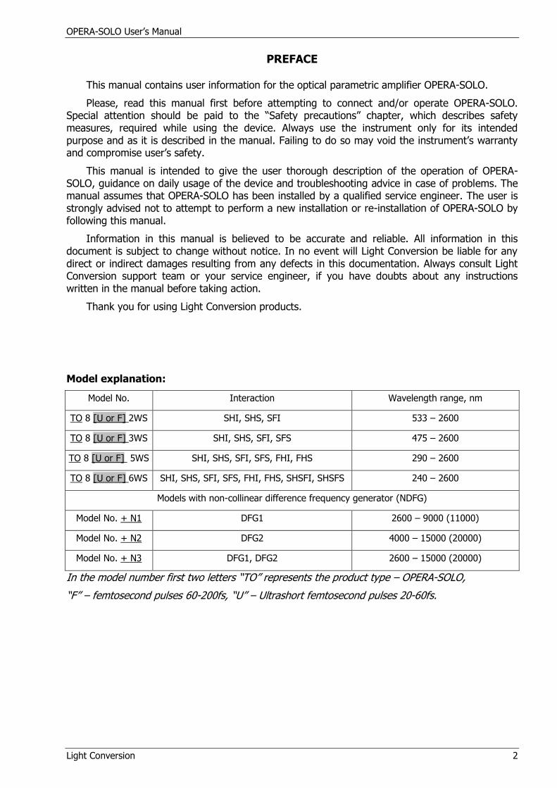
Model explanation:
Model No. Interaction Wavelength range, nm
TO 8 [U or F] 2WS SHI, SHS, SFI 533 – 2600
TO 8 [U or F] 3WS SHI, SHS, SFI, SFS 475 – 2600
TO 8 [U or F] 5WS SHI, SHS, SFI, SFS, FHI, FHS 290 – 2600
TO 8 [U or F] 6WS SHI, SHS, SFI, SFS, FHI, FHS, SHSFI, SHSFS 240 – 2600
Models with non-collinear difference frequency generator (NDFG)
Model No. + N1 DFG1 2600 – 9000 (11000)
Model No. + N2 DFG2 4000 – 15000 (20000)
Model No. + N3 DFG1, DFG2 2600 – 15000 (20000)
In the model number first two letters “TO” represents the product type – OPERA-SOLO,
“F” – femtosecond pulses 60-200fs, “U” – Ultrashort femtosecond pulses 20-60fs.

OPERA-SOLO User’s Manual
Light Conversion 3
ELECTRICAL AND PHYSICAL SPECIFICATIONS
For Indoor use Only
Power Requirements* 24 VDC
Maximum Current 5 A
Weight 40 kg
Altitude Up to 2500 m
Operating temperature (15-40) 0C
Relative humidity (10-70)% (non- condensing)
* OPERA-SOLO is powered by external power supply 100-240 VAC, 1,6 A max provided by the
manufacturer. Contact „Light Conversion“ support team before using power supply from other manufacturers.
OPERA-SOLO is tested with the power supply and the control software shipped with the system. Using any other power supply and/or software to control the OPERA-SOLO system may
cause damage to the instrument and may also void the warranty.
OPERA-SOLO User’s Manual
Light Conversion 4
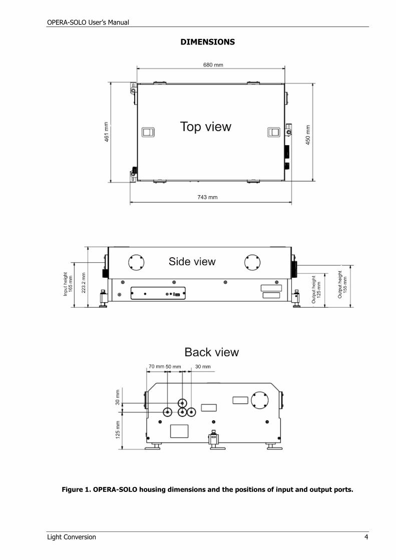
DIMENSIONS
Figure 1. OPERA-SOLO housing dimensions and the positions of input and output ports.
OPERA-SOLO User’s Manual
Light Conversion 5
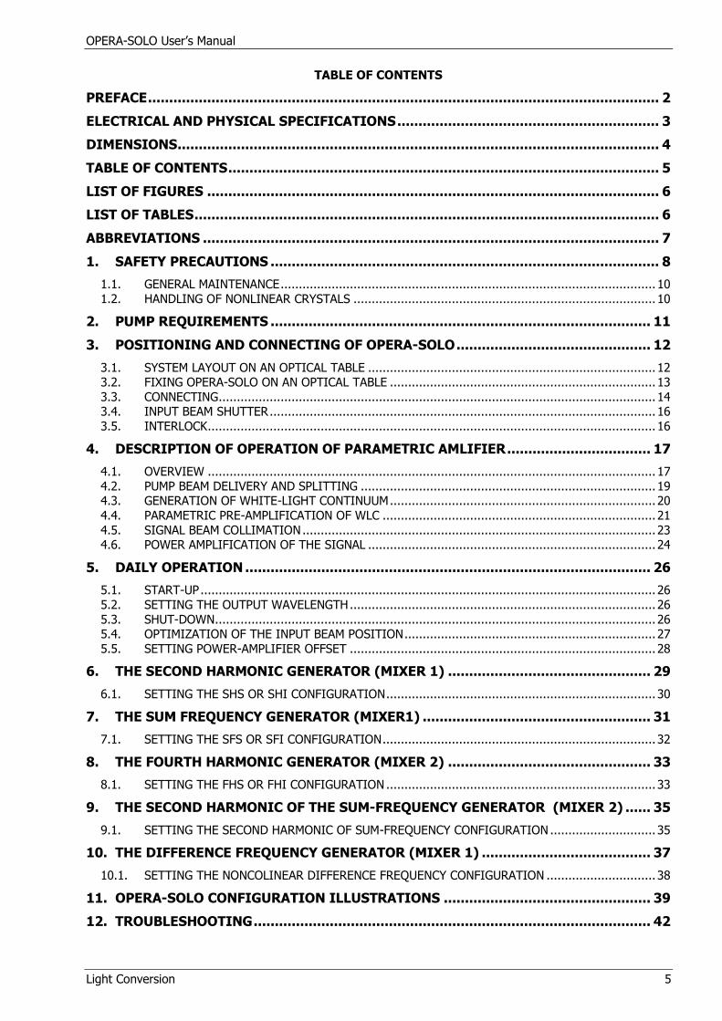
TABLE OF CONTENTS
PREFACE ......................................................................................................................... 2
ELECTRICAL AND PHYSICAL SPECIFICATIONS .............................................................. 3
DIMENSIONS .................................................................................................................. 4
TABLE OF CONTENTS ...................................................................................................... 5
LIST OF FIGURES ........................................................................................................... 6
LIST OF TABLES .............................................................................................................. 6
ABBREVIATIONS ............................................................................................................ 7
1. SAFETY PRECAUTIONS ............................................................................................ 8
1.1. GENERAL MAINTENANCE ....................................................................................................... 10 1.2. HANDLING OF NONLINEAR CRYSTALS ................................................................................... 10
2. PUMP REQUIREMENTS .......................................................................................... 11
3. POSITIONING AND CONNECTING OF OPERA-SOLO .............................................. 12
3.1. SYSTEM LAYOUT ON AN OPTICAL TABLE ............................................................................... 12 3.2. FIXING OPERA-SOLO ON AN OPTICAL TABLE ......................................................................... 13 3.3. CONNECTING ........................................................................................................................ 14 3.4. INPUT BEAM SHUTTER .......................................................................................................... 16 3.5. INTERLOCK ........................................................................................................................... 16
4. DESCRIPTION OF OPERATION OF PARAMETRIC AMLIFIER .................................. 17
4.1. OVERVIEW ........................................................................................................................... 17 4.2. PUMP BEAM DELIVERY AND SPLITTING ................................................................................. 19 4.3. GENERATION OF WHITE-LIGHT CONTINUUM ......................................................................... 20 4.4. PARAMETRIC PRE-AMPLIFICATION OF WLC ........................................................................... 21 4.5. SIGNAL BEAM COLLIMATION ................................................................................................. 23 4.6. POWER AMPLIFICATION OF THE SIGNAL ............................................................................... 24
5. DAILY OPERATION ................................................................................................ 26
5.1. START-UP ............................................................................................................................. 26 5.2. SETTING THE OUTPUT WAVELENGTH .................................................................................... 26 5.3. SHUT-DOWN ......................................................................................................................... 26 5.4. OPTIMIZATION OF THE INPUT BEAM POSITION ..................................................................... 27 5.5. SETTING POWER-AMPLIFIER OFFSET .................................................................................... 28
6. THE SECOND HARMONIC GENERATOR (MIXER 1) ................................................ 29
6.1. SETTING THE SHS OR SHI CONFIGURATION .......................................................................... 30
7. THE SUM FREQUENCY GENERATOR (MIXER1) ...................................................... 31
7.1. SETTING THE SFS OR SFI CONFIGURATION ........................................................................... 32
8. THE FOURTH HARMONIC GENERATOR (MIXER 2) ................................................ 33
8.1. SETTING THE FHS OR FHI CONFIGURATION .......................................................................... 33
9. THE SECOND HARMONIC OF THE SUM-FREQUENCY GENERATOR (MIXER 2) ...... 35
9.1. SETTING THE SECOND HARMONIC OF SUM-FREQUENCY CONFIGURATION ............................. 35
10. THE DIFFERENCE FREQUENCY GENERATOR (MIXER 1) ........................................ 37
10.1. SETTING THE NONCOLINEAR DIFFERENCE FREQUENCY CONFIGURATION .............................. 38
11. OPERA-SOLO CONFIGURATION ILLUSTRATIONS ................................................. 39
12. TROUBLESHOOTING .............................................................................................. 42
OPERA-SOLO User’s Manual
Light Conversion 6
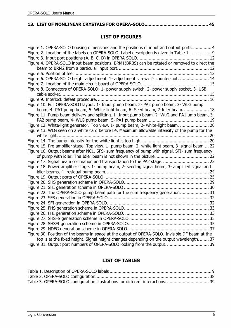
13. LIST OF NONLINEAR CRYSTALS FOR OPERA-SOLO ............................................... 45
LIST OF FIGURES
Figure 1. OPERA-SOLO housing dimensions and the positions of input and output ports. .............. 4 Figure 2. Location of the labels on OPERA-SOLO. Label description is given in Table 1. ................ 9 Figure 3. Input port positions (A, B, C, D) in OPERA-SOLO. ...................................................... 12 Figure 4. OPERA-SOLO input beam positions. BRM1(BRBS) can be rotated or removed to direct the
beam to BRM2 from a particular input port. ..................................................................... 12 Figure 5. Position of feet ....................................................................................................... 13 Figure 6. OPERA-SOLO height adjustment. 1- adjustment screw; 2- counter-nut. ...................... 14 Figure 7. Location of the main circuit board of OPERA-SOLO .................................................... 15 Figure 8. Connectors of OPERA-SOLO: 1- power supply switch, 2- power supply socket, 3- USB
cable socket. ................................................................................................................. 15 Figure 9. Interlock defeat procedure. ..................................................................................... 16 Figure 10. Full OPERA-SOLO layout. 1- Input pump beam, 2- PA2 pump beam, 3- WLG pump
beam, 4- PA1 pump beam, 5- White light beam, 6- Seed beam, 7-Idler beam. ................... 18 Figure 11. Pump beam delivery and splitting. 1- Input pump beam, 2- WLG and PA1 ump beam, 3-
PA2 pump beam, 4- WLG pump beam, 5- PA1 pump beam. .............................................. 19 Figure 12. White-light generator. Top view. 1- pump beam, 2- white-light beam. ...................... 20 Figure 13. WLG seen on a white card before L4. Maximum allowable intensity of the pump for the
white light. ................................................................................................................... 20 Figure 14. The pump intensity for the white light is too high. ................................................... 20 Figure 15. Pre-amplifier stage. Top view. 1- pump beam, 2- white-light beam, 3- signal beam. ... 22 Figure 16. Output beams after NC1. SFS- sum frequency of pump with signal, SFI- sum frequency
of pump with idler. The Idler beam is not shown in the picture. ........................................ 22 Figure 17. Signal beam collimation and transportation to the PA2 stage. ................................... 23 Figure 18. Power amplifier stage. 1- pump beam, 2- seeding signal beam, 3- amplified signal and
idler beams, 4- residual pump beam. .............................................................................. 24 Figure 19. Output ports of OPERA-SOLO. ............................................................................... 25 Figure 20. SHS generation scheme in OPERA-SOLO. ................................................................ 29 Figure 21. SHI generation scheme in OPERA-SOLO ................................................................. 30 Figure 22. The OPERA-SOLO pump beam path for the sum frequency generation. ..................... 31 Figure 23. SFS generation in OPERA-SOLO. ............................................................................ 32 Figure 24. SFI generation in OPERA-SOLO. ............................................................................. 32 Figure 25. FHS generation scheme in OPERA-SOLO. ................................................................ 33 Figure 26. FHI generation scheme in OPERA-SOLO. ................................................................ 33 Figure 27. SHSFS generation scheme in OPERA-SOLO. ............................................................ 35 Figure 28. SHSFI generation scheme in OPERA-SOLO. ............................................................. 35 Figure 29. NDFG generation scheme in OPERA-SOLO. ............................................................. 37 Figure 30. Position of the beams in space at the output of OPERA-SOLO. Invisible DF beam at the
top is at the fixed height. Signal height changes depending on the output wavelength. ....... 37 Figure 31. Output port numbers of OPERA-SOLO looking from the output. ................................ 39
LIST OF TABLES
Table 1. Description of OPERA-SOLO labels .............................................................................. 9 Table 2. OPERA-SOLO configuration. ...................................................................................... 38 Table 3. OPERA-SOLO configuration illustrations for different interactions. ................................ 39
OPERA-SOLO User’s Manual
Light Conversion 7
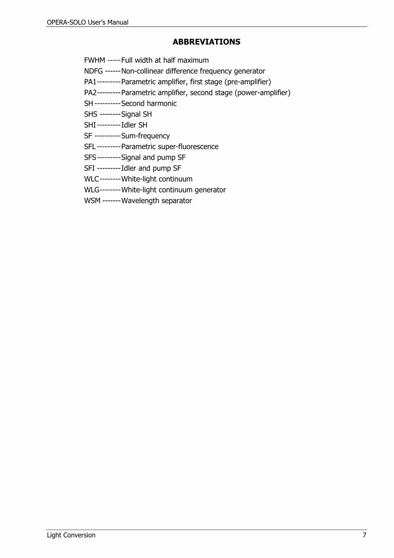
ABBREVIATIONS
FWHM ----- Full width at half maximum
NDFG ------ Non-collinear difference frequency generator
PA1 --------- Parametric amplifier, first stage (pre-amplifier)
PA2 --------- Parametric amplifier, second stage (power-amplifier)
SH ---------- Second harmonic
SHS -------- Signal SH
SHI --------- Idler SH
SF ---------- Sum-frequency
SFL --------- Parametric super-fluorescence
SFS --------- Signal and pump SF
SFI --------- Idler and pump SF
WLC -------- White-light continuum
WLG -------- White-light continuum generator
WSM ------- Wavelength separator
OPERA-SOLO User’s Manual Safety Precautions
Light Conversion 8
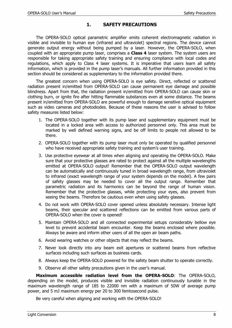
1. SAFETY PRECAUTIONS
The OPERA-SOLO optical parametric amplifier emits coherent electromagnetic radiation in visible and invisible to human eye (infrared and ultraviolet) spectral regions. The device cannot generate output energy without being pumped by a laser. However, the OPERA-SOLO, when coupled with an appropriate pump laser, comprises a Class 4 laser system. The system users are responsible for taking appropriate safety training and ensuring compliance with local codes and regulations, which apply to Class 4 laser systems. It is imperative that users learn all safety information, which is provided in the pump laser’s manuals. All further information provided in this section should be considered as supplementary to the information provided there.
The greatest concern when using OPERA-SOLO is eye safety. Direct, reflected or scattered radiation present in/emitted from OPERA-SOLO can cause permanent eye damage and possible blindness. Apart from that, the radiation present in/emitted from OPERA-SOLO can cause skin or clothing burn, or ignite fire after hitting flammable substances even at some distance. The beams present in/emitted from OPERA-SOLO are powerful enough to damage sensitive optical equipment such as video cameras and photodiodes. Because of these reasons the user is advised to follow safety measures listed below:
1. The OPERA-SOLO together with its pump laser and supplementary equipment must be located in a locked area with access to authorized personnel only. This area must be marked by well defined warning signs, and be off limits to people not allowed to be there.
2. OPERA-SOLO together with its pump laser must only be operated by qualified personnel who have received appropriate safety training and system’s user training.
3. Use protective eyewear at all times when aligning and operating the OPERA-SOLO. Make sure that your protective glasses are rated to protect against all the multiple wavelengths emitted at OPERA-SOLO output! Remember that the OPERA-SOLO output wavelength can be automatically and continuously tuned in broad wavelength range, from ultraviolet to infrared (exact wavelength range of your system depends on the model). A few pairs of safety glasses may be needed to cover all the output range. Remember that parametric radiation and its harmonics can be beyond the range of human vision. Remember that the protective glasses, while protecting your eyes, also prevent from seeing the beams. Therefore be cautious even when using safety glasses.
4. Do not work with OPERA-SOLO cover opened unless absolutely necessary. Intense light beams, their specular and scattered reflections can be emitted from various parts of OPERA-SOLO when the cover is opened!
5. Maintain OPERA-SOLO and all connected experimental setups considerably bellow eye level to prevent accidental beam encounter. Keep the beams enclosed where possible. Always be aware and inform other users of all the open air beam paths.
6. Avoid wearing watches or other objects that may reflect the beams.
7. Never look directly into any beam exit apertures or scattered beams from reflective surfaces including such surfaces as business cards.
8. Always keep the OPERA-SOLO powered for the safety beam shutter to operate correctly.
9. Observe all other safety precautions given in the user’s manual.
Maximum accessible radiation level from the OPERA-SOLO: The OPERA-SOLO, depending on the model, produces visible and invisible radiation continuously tunable in the maximum wavelength range of 185 to 22000 nm with a maximum of 50W of average pump power, and 5 mJ maximum energy per 20 to 300 femtosecond pulse.
Be very careful when aligning and working with the OPERA-SOLO!
OPERA-SOLO User’s Manual Safety Precautions
Light Conversion 9
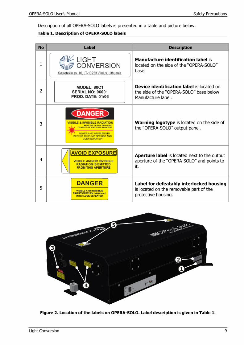
Description of all OPERA-SOLO labels is presented in a table and picture below.
Table 1. Description of OPERA-SOLO labels
No Label Description
1
Manufacture identification label is located on the side of the “OPERA-SOLO” base.
2
Device identification label is located on the side of the “OPERA-SOLO” base below Manufacture label.
3
Warning logotype is located on the side of the “OPERA-SOLO” output panel.
4
Aperture label is located next to the output aperture of the “OPERA-SOLO” and points to it.
5
Label for defeatably interlocked housing is located on the removable part of the protective housing.
Figure 2. Location of the labels on OPERA-SOLO. Label description is given in Table 1.
OPERA-SOLO User’s Manual Safety Precautions
Light Conversion 10
1.1. General maintenance
OPERA-SOLO does not have any consumable parts.
Cleaning:
Exterior of the OPERA-SOLO housing can be cleaned with soft cloth moistened with Ethanol. Do not use Acetone! Make sure that the dust does not contaminate the external or internal optics while cleaning!
Never clean inside of the housing due to the risk of optics and crystal contamination.
Warning! Never touch the optics with bare hands. Clean surfaces immediately, if touched.
Clean optics only when necessary. When cleaning, use acetone (methanol, ethyl acetate) of >99.5% purity.
Do not attempt to clean the surface of gold mirrors due to the risk of damage.
1.2. Handling of nonlinear crystals
Nonlinear crystals used in OPERA-SOLO for generation of IR tunable pulses as well as the crystals for second harmonics or sum frequency generation are fabricated of beta-barium borate (BBO) or lithium triborate (LBO). These crystals are known to be hygroscopic. The Crystals used in OPERA-SOLO have protective coatings. However, the humidity level in the laboratory should be
(nevertheless) kept less than 70%. If you do not intend to operate OPERA-SOLO for a long period, you can remove the crystals out of the mounts (together with turret in case of mixer crystals) and pack them in sealed container with desiccant.
When cleaning the faces of crystals use acetone (methanol, ethyl acetate) of >99.5% purity.
Warning! Never touch the crystals with bare hands. Clean surfaces immediately, if touched.
The crystals used for difference frequency generation are not hygroscopic. GaSe crystal is very soft. The surfaces can be scratched easily and the crystal bends if even small force is applied.
Warning! Do not attempt to clean the surfaces of GaSe and other crystals thinner than 0.5mm due to risk of damage.

OPERA-SOLO User’s Manual Pump Requirements
Light Conversion 11
2. PUMP REQUIREMENTS
Input Wavelength 770-830 nm
Pulse energy 0.15 - 3.5 mJ 0.15 - 4 mJ 0.15 - 5 mJ
Pulse duration (FWHM) 20 - 60 fs 60 - 150 fs 150 - 200 fs
Polarization Horizontal
Spectral width <1.2 times transform limit
Energy instability <1% RMS
Instability of pulse duration <1% pulse-to-pulse
Pulse front tilt <10% of pulsewidth
Pulse contrast <5% of output energy in background
Spatial mode quality M2<1.3
Beam astigmatism <0.15
Input beam spatial profile Gaussian - Hyper Gaussian
Intensity modulation <15%
No hot spots
Beam pointing instability <0.1 x (diffraction limit)
Beam divergence <1.5 x (diffraction limit)
Beam height 160 mm from optical table
Beam size, 1/e2 <13 mm (optional external telescope should be used for the beam size 13 - 28 mm)
Good performance of OPERA-SOLO requires high pump quality in terms of both time and space coherence. In other words ideal pump is diffraction-limited beam and transform-limited, high contrast pulse. Unlike with conventional lasers with coherent pump, the phase modulation of pump pulse and/or beam inevitably influences the output. To some extent, the performance of OPERA-SOLO is an indicator of quality of the pump laser radiation.
In femtosecond systems that use nowadays-standard chirped pulse amplification technique (CPA), there are specific possible causes of distorted beam or pulse. Some of them are discussed below.
Spatial beam quality. The non-uniformity of the beam reduces the energy conversion rate. Presence of hot spots in the beam may “ignite” small-scale self-focusing that in turn leads to phase modulation. In the power amplifiers, hot spots can also produce parametric superfluorescence, which prevents of rising average power in order to achieve high conversion in to parametric radiation. Presence of supercontinuum with low parametric conversion may indicate that the beam profile is not uniform.
Spatial/temporal beam distortion. In contrast to long pulse lasers, astigmatism introduced by improperly aligned lenses of beam expanders/reducers lead to distortion of temporal profile of the pulse across the beam. This makes it impossible to overlap pump and signal pulses over the entire beam aperture in OPERA-SOLO.
Tilted pulses. This phenomenon manifests itself in similar way as discussed above. However, it originates from improper pulse compressor alignment. Tilted pulses are produced when the angular dispersion is not completely cancelled. The problem with this kind of distortion is that it can be easily overlooked using standard diagnostics equipment such as autocorrelator.
Underseeded regenerative amplifiers. The seed pulses for regenerative amplifier can be too week due to low oscillator power, poor mode matching or improper Pockels cell timing. This results in rather high energy content in the background. The background can be detectable neither by oscilloscope nor by autocorrelator. Simple test for the background is measurement of build-up time of unseeded and seeded regenerative amplifier. In last case the build-up time should be shorter at least by 15-20%.

OPERA-SOLO User’s Manual Positioning and Connecting of OPERA-SOLO
Light Conversion 12
3. POSITIONING AND CONNECTING OF OPERA-SOLO
3.1. System Layout on an Optical Table
It is recommended to position OPERA-SOLO along the one side of an optical table about 10-20cm from the table edge. Such positioning allows a convenient access while operating or aligning the device.
OPERA-SOLO is build to accept a beam from different directions (Figure 3).
Figure 3. Input port positions (A, B, C, D) in OPERA-SOLO.
Figure 4. OPERA-SOLO input beam positions. BRM1(BRBS) can be rotated or removed to direct the beam to BRM2 from a particular input port.
OPERA-SOLO User’s Manual Positioning and Connecting of OPERA-SOLO
Light Conversion 13
OPERA-SOLO can accept the maximum beam size of about 13 mm at 1/e2 intensity level. An additional external telescope is needed with amplifiers delivering a larger beam. It is important that the beam would not clip on any aperture before OPERA-SOLO and inside of it in order to achieve good output beam quality. Figure 4 shows a setup of OPERA-SOLO with the internal telescope. The flat mirrors BRM1 and BRM2 direct the beam to a down-collimating telescope. An internal telescope is used to reduce the beam size to 6-8 mm at 1/e2 level.
A beam splitter (BRBS) may be used in OPERA-SOLO instead of BRM1 if needed.
OPERA-SOLO is pumped by high peak intensity femtosecond pulses. It is strongly recommended to use only reflective optics for such pump pulses. It is also recommended to avoid any dispersive materials in the beam before OPERA-SOLO as the intensities of pump pulses are close to the threshold of self-phase modulation, self-focusing and other nonlinear processes. Always use 50% or higher reflectivity beam-splitters of minimum thickness should beam splitting be needed before OPERA-SOLO.
3.2. Fixing OPERA-SOLO on an Optical Table
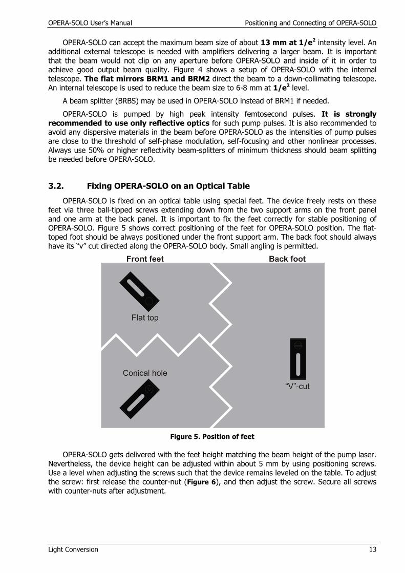
OPERA-SOLO is fixed on an optical table using special feet. The device freely rests on these feet via three ball-tipped screws extending down from the two support arms on the front panel and one arm at the back panel. It is important to fix the feet correctly for stable positioning of OPERA-SOLO. Figure 5 shows correct positioning of the feet for OPERA-SOLO position. The flat-toped foot should be always positioned under the front support arm. The back foot should always have its “v” cut directed along the OPERA-SOLO body. Small angling is permitted.
Figure 5. Position of feet
OPERA-SOLO gets delivered with the feet height matching the beam height of the pump laser. Nevertheless, the device height can be adjusted within about 5 mm by using positioning screws. Use a level when adjusting the screws such that the device remains leveled on the table. To adjust the screw: first release the counter-nut (Figure 6), and then adjust the screw. Secure all screws with counter-nuts after adjustment.

OPERA-SOLO User’s Manual Positioning and Connecting of OPERA-SOLO
Light Conversion 14
Figure 6. OPERA-SOLO height adjustment. 1- adjustment screw; 2- counter-nut.
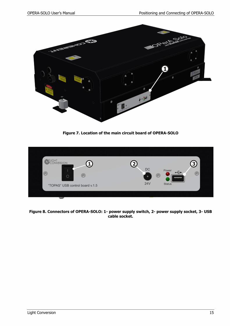
3.3. Connecting
OPERA-SOLO has one connection panel. Figure 7 shows the location of the main circuit board. The sequence of connecting OPERA-SOLO should be as follows:
1. Make sure the main circuit board switch is in “OFF” position;
2. Connect power supply to main circuit board (OPERA-SOLO) –(Figure 7);
3. Install WinTOPAS 3 from your CD as described in WinTOPAS start guide;
4. Connect power supply to power outlet;
5. Connect USB cable to OPERA-SOLO and computer – (Figure 8);
6. Turn the main circuit board switch to “ON” position;
7. Install the OPERA-SOLO driver as described in WinTOPAS start guide.
Use only power supplies from Light Conversion or contact our support team before connecting power supply from other manufacturers. The power supply from Light Conversion is suitable to both 110V and 220V outlets.
Always check that the supply and its cables are in proper condition and do not show any damage to any part of the insulation, before connecting.
Power LED (RED) should be on and Status LED (Green) should blink with intervals of ~ 1 second during normal operation of OPERA-SOLO control board.
Should more than one OPERA-SOLO be controlled by the same computer, proceed through steps from 1 to 2 with every OPERA-SOLO first. A USB-hub can be used if the computer does not have enough USB ports. Light Conversion does not guarantee proper operation of OPERA-SOLO with non-branded USB-hubs.
WinTOPAS software can be started after completing all 7 steps. Consult WinTOPAS start guide for information on software usage. Register at the Light Conversion web site (www.lightcon.com, Client Area) for the newest version of the software.
OPERA-SOLO User’s Manual Positioning and Connecting of OPERA-SOLO
Light Conversion 15
Figure 7. Location of the main circuit board of OPERA-SOLO
Figure 8. Connectors of OPERA-SOLO: 1- power supply switch, 2- power supply socket, 3- USB
cable socket.
OPERA-SOLO User’s Manual Positioning and Connecting of OPERA-SOLO
Light Conversion 16
3.4. Input Beam Shutter
OPERA-SOLO is usually equipped with an input beam shutter (except for the early models). The shutter is positioned inside of OPERA-SOLO after the telescope (Figure 4). Its primary purpose is to enhance user safety while working with OPERA-SOLO. It automatically blocks the pump beam while OPERA-SOLO wavelength is tuned or motor reset is performed. It can also be used to block or unblock the input beam to OPERA-SOLO on users will.
OPERA-SOLO models have shutters, which can be operated from a computer only. A computer controlled shutter can be operated from the WinTOPAS software. WinTOPAS displays a warning message when the shutter is opened.
Warning! Always keep the OPERA-SOLO powered for the shutter to operate correctly and for the WinTOPAS to display correct shutter status.
The shutter state can be controlled from the main WinTOPAS window with a knob located in the toolbar (see section 5.4 of the WinTOPAS start guide).
3.5. Interlock
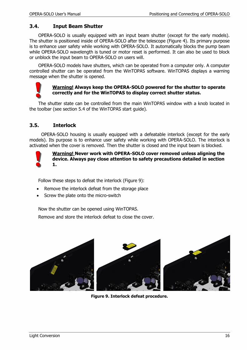
OPERA-SOLO housing is usually equipped with a defeatable interlock (except for the early models). Its purpose is to enhance user safety while working with OPERA-SOLO. The interlock is activated when the cover is removed. Then the shutter is closed and the input beam is blocked.
Warning! Never work with OPERA-SOLO cover removed unless aligning the device. Always pay close attention to safety precautions detailed in section 1.
Follow these steps to defeat the interlock (Figure 9):
Remove the interlock defeat from the storage place
Screw the plate onto the micro-switch
Now the shutter can be opened using WinTOPAS.
Remove and store the interlock defeat to close the cover.
Figure 9. Interlock defeat procedure.

OPERA-SOLO User’s Manual Description of Operation of Parametric amplifier
Light Conversion 17
4. DESCRIPTION OF OPERATION OF PARAMETRIC AMLIFIER
4.1. Overview
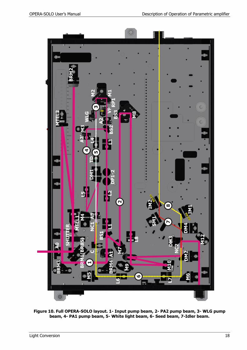
OPERA-SOLO is a two-stage parametric amplifier of white-light continuum. Its basic configuration comprises of several subunits: pump beam delivery and splitting optics (PO), white-light continuum generator (WLG), a pre-amplifier or the first amplification stage (PA1), a signal beam expander-collimator (SE) and a power amplifier or the second amplification stage (PA2). These subunits are arranged in a single compact unit. The device employs computer controlled translation and rotation stages that allow fast and precise optimization of positions of certain optics when tuning the output wavelength of OPERA-SOLO. The full layout of the OPERA-SOLO parametric amplification part is presented in Fig. 10. The following paragraph briefly describes operation of the device.
Small fraction (about 1-3 µJ) of pump pulses at 800 nm wavelength is used to produce white-light continuum (WLC) in a sapphire plate. The WLC beam and another fraction (30-70 uJ) of the pump beam are focused into the pre-amplifier crystal. The pulses are timed and overlapped non-collinearly inside the nonlinear crystal, where parametric amplification takes place. A non-collinear geometry is used for easy separation of the amplified signal beam. The residual pump and idler beams are blocked by a beam blocker after the crystal. The signal beam is expanded and collimated by a lens telescope, and transported into the second amplification stage. The power-amplifier is usually pumped by the bulk of the input pump beam. The pump beam size is reduced to achieve necessary pump intensity by a lens-mirror telescope. The beam is kept collimated after the telescope. The pump and signal beams are overlapped collinearly in the second nonlinear crystal. As a result the OPERA-SOLO outputs collimated signal and idler beams. Input beam is at 65 mm height. All the beams inside OPERA-SOLO after the telescope are arrange at the same 25 mm height from baseplate.
Optional internal frequency mixers can be used in OPERA-SOLO to extend the tuning range into visible, ultra violet and/or mid-infrared.
The wavelength tuning in the pre-amplifier stage is achieved by changing the delay of the white-light pulse with respect to the first pump pulse and adjusting the crystal angle for optimal phase matching. The wavelength tuning in the power-amplifier is achieved by adjusting the pre-amplifier wavelength and then optimizing the second crystal angle and signal delay with respect to the second pump beam.
Once OPERA-SOLO is properly adjusted and calibrated the wavelength can be changed easily through a computer using a dedicated software package.
In the following sections you will find more detailed description of each part of OPERA-SOLO.
OPERA-SOLO User’s Manual Description of Operation of Parametric amplifier
Light Conversion 18
Figure 10. Full OPERA-SOLO layout. 1- Input pump beam, 2- PA2 pump beam, 3- WLG pump
beam, 4- PA1 pump beam, 5- White light beam, 6- Seed beam, 7-Idler beam.
OPERA-SOLO User’s Manual Description of Operation of Parametric amplifier
Light Conversion 19
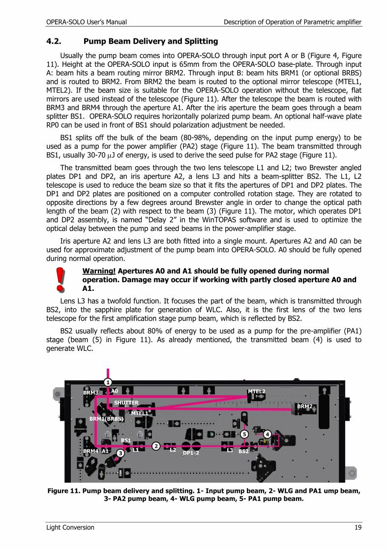
4.2. Pump Beam Delivery and Splitting
Usually the pump beam comes into OPERA-SOLO through input port A or B (Figure 4, Figure 11). Height at the OPERA-SOLO input is 65mm from the OPERA-SOLO base-plate. Through input A: beam hits a beam routing mirror BRM2. Through input B: beam hits BRM1 (or optional BRBS) and is routed to BRM2. From BRM2 the beam is routed to the optional mirror telescope (MTEL1, MTEL2). If the beam size is suitable for the OPERA-SOLO operation without the telescope, flat mirrors are used instead of the telescope (Figure 11). After the telescope the beam is routed with BRM3 and BRM4 through the aperture A1. After the iris aperture the beam goes through a beam splitter BS1. OPERA-SOLO requires horizontally polarized pump beam. An optional half-wave plate RP0 can be used in front of BS1 should polarization adjustment be needed.
BS1 splits off the bulk of the beam (80-98%, depending on the input pump energy) to be used as a pump for the power amplifier (PA2) stage (Figure 11). The beam transmitted through
BS1, usually 30-70 J of energy, is used to derive the seed pulse for PA2 stage (Figure 11).
The transmitted beam goes through the two lens telescope L1 and L2; two Brewster angled plates DP1 and DP2, an iris aperture A2, a lens L3 and hits a beam-splitter BS2. The L1, L2 telescope is used to reduce the beam size so that it fits the apertures of DP1 and DP2 plates. The DP1 and DP2 plates are positioned on a computer controlled rotation stage. They are rotated to opposite directions by a few degrees around Brewster angle in order to change the optical path length of the beam (2) with respect to the beam (3) (Figure 11). The motor, which operates DP1 and DP2 assembly, is named “Delay 2” in the WinTOPAS software and is used to optimize the optical delay between the pump and seed beams in the power-amplifier stage.
Iris aperture A2 and lens L3 are both fitted into a single mount. Apertures A2 and A0 can be used for approximate adjustment of the pump beam into OPERA-SOLO. A0 should be fully opened during normal operation.
Warning! Apertures A0 and A1 should be fully opened during normal operation. Damage may occur if working with partly closed aperture A0 and A1.
Lens L3 has a twofold function. It focuses the part of the beam, which is transmitted through BS2, into the sapphire plate for generation of WLC. Also, it is the first lens of the two lens telescope for the first amplification stage pump beam, which is reflected by BS2.
BS2 usually reflects about 80% of energy to be used as a pump for the pre-amplifier (PA1) stage (beam (5) in Figure 11). As already mentioned, the transmitted beam (4) is used to generate WLC.
Figure 11. Pump beam delivery and splitting. 1- Input pump beam, 2- WLG and PA1 ump beam, 3- PA2 pump beam, 4- WLG pump beam, 5- PA1 pump beam.

OPERA-SOLO User’s Manual Description of Operation of Parametric amplifier
Light Conversion 20
4.3. Generation of White-light Continuum
In OPERA-SOLO the seed pulse for parametric amplification is derived from a femtosecond continuum that is generated in a sapphire plate. Figure 12 presents WLC generation scheme.
The pump beam transmitted through BS2 is used to generate WLC. The beam goes though a variable density filter VF, a retro-reflector M1-M2 and a half-wave plate RP1 into a sapphire plate WLG (Figure 12). The beam is focused into WLG by L3 lens. The VF is used for smooth adjustment of the pump beam intensity inside WLG. M1 and M2 mirrors are positioned on a computer controlled delay line. The motor, which operates the delay line, is named “Delay 1” in the WinTOPAS software and is used to optimize the optical delay between the pump and WLC beams in the pre-amplifier (PA1) stage. RP1 changes the pump beam polarization into vertical in order to generate vertically polarized WLC.
Figure 12. White-light generator. Top view. 1- pump beam, 2- white-light beam.
Certain pump intensity is required in order to generate suitable WLC. The pump intensity depends on the pump pulse duration, pulse contrast, beam waist size inside WLG and, finally, the pulse energy. The last parameter is easily adjusted in OPERA-SOLO by using VF. A diverging WLC beam can be seen on a paper card positioned after WLG once proper pump intensity is reached. The aim is to produce a stable, yet single-filament WLC beam (Figure 13). In the Figure 14 you can see the white-light with too high pump intensity.
Figure 13. WLG seen on a white card before
L4. Maximum allowable intensity of the pump for the white light.
Figure 14. The pump intensity for the white
light is too high.
After WLG, WLC goes through the lens L4, dispersive plate TD, dichroic mirror DM1 and an iris aperture A3 into a nonlinear crystal NC1 (Figure 15). Lens L4 focuses the WLC beam into NC1.

OPERA-SOLO User’s Manual Description of Operation of Parametric amplifier
Light Conversion 21
TD is used to stretch the WLC pulse in time. Mirror DM1 combines the WLC beam with the pump beam by transmitting the WLC beam and reflecting the pump beam. The Aperture A3 is used as a position reference for the WLC beam. Section 4.2 mentioned using apertures A2, A1 and A0 for approximate adjustment of the input pump beam into OPERA-SOLO. Aperture A3 can be used for more accurate adjustment of the pump beam.
4.4. Parametric Pre-amplification of WLC
WLC is pre-amplified in OPERA-SOLO in a nonlinear crystal NC1 using a fresh pump beam reflected from BS2. Figure 15 shows the pre-amplifier scheme.
The pre-amplifier pump beam path is as follows: BS2- M3- L5- M4- DM1- A3- NC1. The pump beam is focused using a telescope of two positive lenses L3 and L5. L3 is the same lens, which focuses the WLC pump into WLG. It also focuses the pre-amplifier pump into the air in front of L5. Then L5 refocuses the beam after the NC1. The WLC beam path into NC1 is described in the previous section.
Notice, that the pump beam is not centered on aperture A3. A3 is rather used to center the WLC beam. A3 should be fully opened during normal operation.
The pump and WLC beams are intersected non-collinearly inside NC1. The non-collinear geometry has been chosen to have easy separation of the signal beam (the amplified WLC after NC1 is called signal) from the residual pump and idler beams. Usually, the angle between WLC and the pump is such that the beams are separated by 1.5-3 mm just after DM1. The residual pump and idler beams appear on the right hand side (while following along the beam paths) after NC1 and are dumped by a beam blocker. Usually, the beam blocker is positioned in front of the compensator C. Then only the signal beam passes C and hits the mirror M5. However, in some cases the residual pump beam can be blocked after C.
Warning! It is important that the residual pump beam is always blocked before M5. M5 is a metallic mirror and can be easily damaged by the intense pump beam.
A number of conditions must be met for successful operation of the pre-amplifier stage:
proper pump intensity
proper WLC intensity
overlap of pump and WLC in space
overlap of pump and specific portion of WLC in time
correct NC1 crystal angle
The pump intensity in NC1 should be high enough for efficient amplification of WLC. The pump intensity should be at the threshold of generation of parametric super-fluorescence (SFL). The pre-amplifier pump must not generate WLC in NC1.
Warning! Never operate OPERA-SOLO if the pre-amplifier pump beam generates WLC inside NC1 crystal. This can lead to damage of the crystal.
Correct pump intensity is usually chosen in the following way: first the WLC beam is blocked before DM1. Then the NC1 is rotated to be approximately perpendicular to the OPERA-SOLO side (the pump should hit the crystal close to a 0 deg angle with its normal). Lens L5 position is adjusted to obtain SFL after the crystal (green-yellowish light on side of the pump beam). An alternative way is to leave L5 in place, and instead partially close/open aperture A2 to optimize the level of SFL. The WLG pump energy must be re-optimized using VF in the latter case.

OPERA-SOLO User’s Manual Description of Operation of Parametric amplifier
Light Conversion 22
Correct WLC intensity is achieved first by optimizing the WLC generation as described in the previous section and then by optimizing the WLC focusing into NC1. Visual inspection of WLC focus point may be misleading since the infrared part of WLC used for amplification (1100-1600 nm range) is not focused to the same point as visible part due to chromatic aberration of the lens. The best way to optimize the focusing is to tune the signal wavelength into 1500-1600 nm range and then try to find position of L4, which gives the most efficient amplification of WLC (the highest signal energy after NC1).
Figure 15. Pre-amplifier stage. Top view. 1- pump beam, 2- white-light beam, 3- signal beam.
The pump and WLC beams must have good spatial overlap inside NC1 in order to achieve efficient amplification. Usually the M4 mirror is used, should fine optimization of the overlap be needed. Besides spatial overlap, the pump pulse should overlap with specific part of the dispersed WLC in the WLC wavelength range of 1100-1600 nm. The signal wavelength corresponds to the WLC wavelength overlapped with the pump pulse. The signal wavelength is changed by changing the delay of WLC with respect to the pump pulse. “Delay 1” motor can be used through WinTOPAS software to change this delay.
NC1 angle should be adjusted to achieve phase matching and thus efficient amplification for specific signal wavelength set by “Delay 1”. NC1 is positioned on a computer controlled rotation stage and can be operated through WinTOPAS software as “Crystal 1”. The same rotation stage moves the compensator C at the same time but in opposite direction. The compensator function is to compensate the shift of the signal beam due to rotation of NC1.
Figure 16 shows output beams of well functioning pre-amplifier stage. The beams are best monitored on a paper card positioned in front of C. The beam block should be removed to see all the beams.
Warning! Always put the beam block back in place to block the pump beam before removing a paper card!
The signal beam is in the center of WLC beam. One can see a red, yellowish or greenish spot corresponding to the second harmonic (SH) of signal on top of WLC spot for the signal wavelength between 1100-1400 nm. One can also always see two sum-frequency spots, which accompany parametric amplification of the signal. The spot between the pump and WLC is sum-frequency between the pump and the signal. Its color is blue-green depending on signal wavelength. The spot on the right side of the pump originates from sum-frequency of pump with idler. It has green-yellowish color depending on the signal wavelength.
WLC
Signal
SFS SFI
Pump
Figure 16. Output beams after NC1. SFS- sum frequency of pump with signal, SFI- sum frequency of pump with idler. The Idler beam is not shown in the picture.
OPERA-SOLO User’s Manual Description of Operation of Parametric amplifier
Light Conversion 23
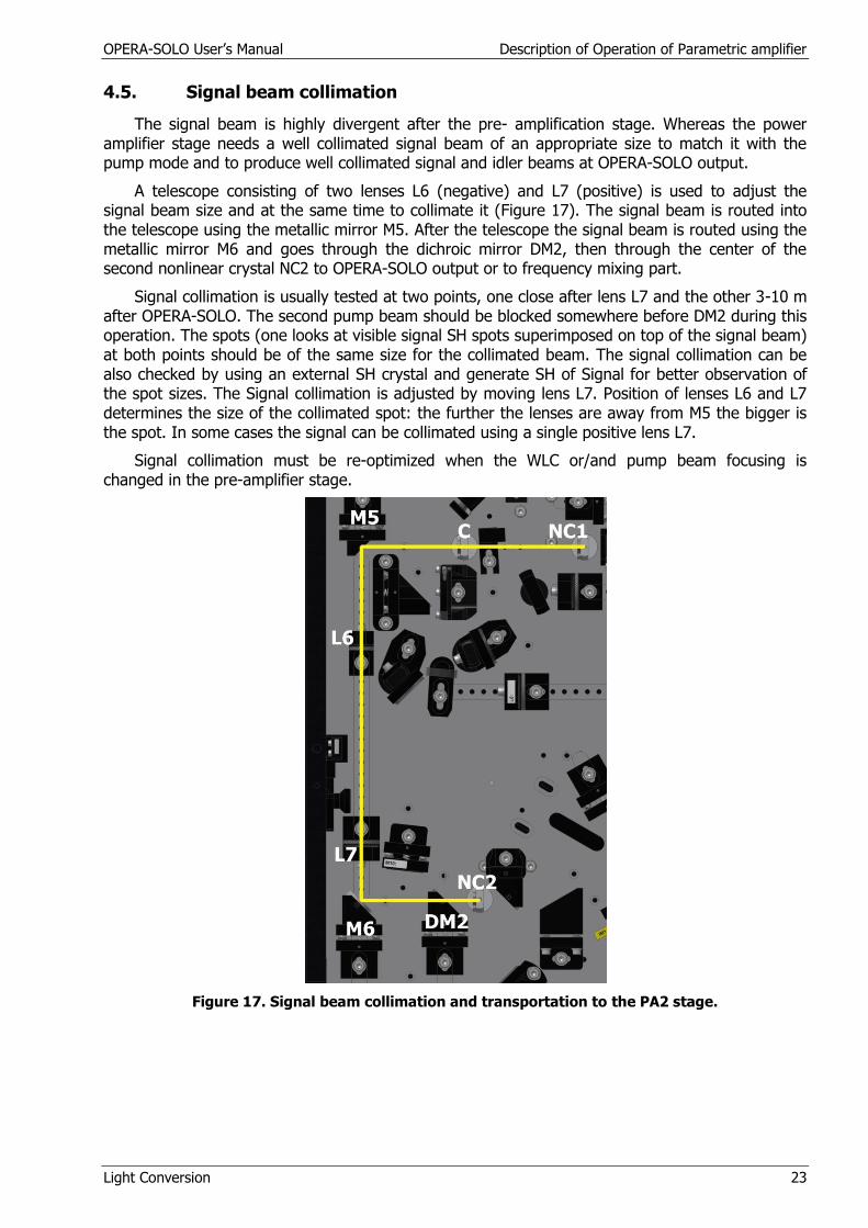
4.5. Signal beam collimation
The signal beam is highly divergent after the pre- amplification stage. Whereas the power amplifier stage needs a well collimated signal beam of an appropriate size to match it with the pump mode and to produce well collimated signal and idler beams at OPERA-SOLO output.
A telescope consisting of two lenses L6 (negative) and L7 (positive) is used to adjust the signal beam size and at the same time to collimate it (Figure 17). The signal beam is routed into the telescope using the metallic mirror M5. After the telescope the signal beam is routed using the metallic mirror M6 and goes through the dichroic mirror DM2, then through the center of the second nonlinear crystal NC2 to OPERA-SOLO output or to frequency mixing part.
Signal collimation is usually tested at two points, one close after lens L7 and the other 3-10 m after OPERA-SOLO. The second pump beam should be blocked somewhere before DM2 during this operation. The spots (one looks at visible signal SH spots superimposed on top of the signal beam) at both points should be of the same size for the collimated beam. The signal collimation can be also checked by using an external SH crystal and generate SH of Signal for better observation of the spot sizes. The Signal collimation is adjusted by moving lens L7. Position of lenses L6 and L7 determines the size of the collimated spot: the further the lenses are away from M5 the bigger is the spot. In some cases the signal can be collimated using a single positive lens L7.
Signal collimation must be re-optimized when the WLC or/and pump beam focusing is changed in the pre-amplifier stage.
Figure 17. Signal beam collimation and transportation to the PA2 stage.
OPERA-SOLO User’s Manual Description of Operation of Parametric amplifier
Light Conversion 24
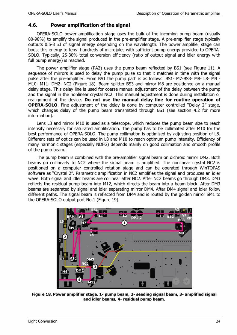
4.6. Power amplification of the signal
OPERA-SOLO power amplification stage uses the bulk of the incoming pump beam (usually 80-98%) to amplify the signal produced in the pre-amplifier stage. A pre-amplifier stage typically outputs 0.5-3 J of signal energy depending on the wavelength. The power amplifier stage can boost this energy to tens- hundreds of microjules with sufficient pump energy provided to OPERA-SOLO. Typically, 25-30% total conversion efficiency (ratio of output signal and idler energy with full pump energy) is reached.
The power amplifier stage (PA2) uses the pump beam reflected by BS1 (see Figure 11). A sequence of mirrors is used to delay the pump pulse so that it matches in time with the signal pulse after the pre-amplifier. From BS1 the pump path is as follows: BS1- M7-BS3- M8- L8- M9 - M10- M11- DM2- NC2 (Figure 18). Beam splitter BS3 and mirror M8 are positioned on a manual delay stage. This delay line is used for coarse manual adjustment of the delay between the pump and the signal in the nonlinear crystal NC2. This manual adjustment is done during installation or realignment of the device. Do not use the manual delay line for routine operation of OPERA-SOLO. Fine adjustment of the delay is done by computer controlled “Delay 2” stage, which changes delay of the pump beam transmitted through BS1 (see section 4.2 for more information).
Lens L8 and mirror M10 is used as a telescope, which reduces the pump beam size to reach intensity necessary for saturated amplification. The pump has to be collimated after M10 for the best performance of OPERA-SOLO. The pump collimation is optimized by adjusting position of L8. Different sets of optics can be used in L8 and M10 to reach optimum pump intensity. Efficiency of many harmonic stages (especially NDFG) depends mainly on good collimation and smooth profile of the pump beam.
The pump beam is combined with the pre-amplifier signal beam on dichroic mirror DM2. Both beams go collinearly to NC2 where the signal beam is amplified. The nonlinear crystal NC2 is positioned on a computer controlled rotation stage and can be operated through WinTOPAS software as “Crystal 2”. Parametric amplification in NC2 amplifies the signal and produces an idler wave. Both signal and idler beams are collinear after NC2. After NC2 beams go through DM3. DM3 reflects the residual pump beam into M12, which directs the beam into a beam block. After DM3 beams are separated by signal and idler separating mirror DM4. After DM4 signal and idler follow different paths. The signal beam is reflected from DM4 and is routed by the golden mirror SM1 to the OPERA-SOLO output port No.1 (Figure 19).
Figure 18. Power amplifier stage. 1- pump beam, 2- seeding signal beam, 3- amplified signal
and idler beams, 4- residual pump beam.

OPERA-SOLO User’s Manual Description of Operation of Parametric amplifier
Light Conversion 25
The idler beam goes through the DM4 and is blocked by the mixer stage. If the idler is needed at the output of OPERA-SOLO the golden mirrors IM1 and IM2 are used to route idler beam to the output port (1) (Figure 19). The mirrors IM1 and IM2 have magnetic bases. The mirror IM1 works as a signal beam block and idler reflecting mirror in case the idler beam is needed at the output. If the signal beam is needed at the output then mirror IM1 and IM2 have to be removed and stored on dedicated bases inside OPERA-SOLO.
A number of conditions, similar to those required for pre-amplifier stage, must be met for successful operation of the power amplifier stage:
proper pump intensity
proper seed intensity
overlap of pump and seed in space and time
correct NC2 crystal angle
Pump intensity is adjusted using L8-M10 telescope as described above. Proper pump intensity gives saturated amplification. Saturated amplification can be detected by monitoring of output pulse spectra. Too low pump intensity gives low conversion efficiency, while too high intensity deteriorates amplified pulse and spectrum profile as well as beam profile.
Proper seed intensity is ensured by good performance of the pre-amplifier stage. The pre-amplifier signal should have 0.5-3 J of energy at OPERA-SOLO output depending on signal
wavelength.
The pump and seeding signal beams must be collinear: the beams should overlap in space in NC2 as well as at some distance (3-10 m) after OPERA-SOLO. If the beams are non-collinear, then separated colored spots, a picture similar to that for the pre-amplifier stage given in Figure 16, are seen at some distance from OPERA-SOLO output. Pump mirrors M10 and DM2 can be used for fine optimization of the pump and seed beam overlap.
The timing between the pump and seeding signal pulses is adjusted using computer controlled delay stage “Delay 2”. Finally, the NC2 phase matching angle is adjusted from software using “Crystal 2” control. Both “Delay 2” and “Crystal 2” are adjusted for maximum signal and idler output energy.
WinTOPAS software allows storing OPERA-SOLO motor positions (two motors for pre-amplifier stage “Crystal 1”, “Delay 1” and two motors for the power amplifier stage “Crystal 2”, Delay 2) for each wavelength in a table called calibration file. The calibration file is used for easy change of the OPERA-SOLO output wavelength.
Figure 19. Output ports of OPERA-SOLO.
OPERA-SOLO User’s Manual Daily Operation
Light Conversion 26
5. DAILY OPERATION
Please read SAFETY PRECAUTIONS chapter before using the device.
5.1. Start-up
1. Start the WinTOPAS software and make sure the OPERA-SOLO shutter is closed (the pump beam is blocked in OPERA-SOLO).
2. Switch on and warm-up the OPERA-SOLO pump laser and do day by day checking/ adjustment procedures recommended by the laser manufacturer.
3. Open the shutter using WinTopas and check if output beam is present after OPERA-SOLO. Check the OPERA-SOLO alignment and pump laser performance if OPERA-SOLO gives no output. Avoid random adjustment of the intense pump beam into OPERA-SOLO.
Warning! Wrong beam input into OPERA-SOLO may result in damage of internal optics. Do not leave the shutter opened if OPERA-SOLO gives no output beam.
4. Position a power meter into the OPERA-SOLO output beam and check the output power. Consult the installation report for expected power at the selected wavelength. Optimize the pump laser pulse compressor and input beam direction (use the beam routing mirror closest to the OPERA-SOLO input) for maximum OPERA-SOLO output if needed. Double check your pump laser performance and reset OPERA-SOLO motors if the output power is low. Use optimization procedure 5.4 once sure that the pump laser is working to specifications.
OPERA-SOLO is now ready to be used.
5.2. Setting the output wavelength
To set Signal or Idler wavelength:
1. Type the wavelength into WinTOPAS wavelength window (see section 5.3 of WinTOPAS start guide for more information),
2. If you need the signal beam at the output remove mirrors IM1 and IM2, wavelength separators WSM1 and WSM2 from the beam path. If you need the idler beam, place IM1 and IM2 mirrors on their original positions on the magnetic holders. See table 2 for the output configuration of the OPERA-SOLO.
Warning!. Always close shutter before moving any optics. Use the beam blockers on the output ports of OPERA-SOLO to block the beams that are not intended to be used in your application.
5.3. Shut-down
Exit the WinTOPAS software. Always keep the OPERA-SOLO powered.
OPERA-SOLO User’s Manual Daily Operation
Light Conversion 27
5.4. Optimization of the input beam position
Use the following procedure to optimize the input beam position and direction into OPERA-SOLO:
1. Open OPERA-SOLO cover and defeat the interlock (section 3.5).
2. Put a paper card just after iris A0 (Figure 11) and adjust the pump beam on the iris centre. The iris can be partially closed to better see the beam position. Always fully open the iris after the adjustment has been finished.
Warning! Always look after a paper card in the beam. There is always some risk that the paper card can start burning while hit by the intense beam.
3. Put a paper card in front of the BS1 after the iris A1 and adjust the pump beam on the iris centre. Try to use external mirrors if possible. Adjust BRM2 if needed.
4. Put a paper card in front of mirror M7 (Figure 18) to block the main pump beam. Put another paper card after A2-L3 mount (Figure 12). Open the shutter and check if the beam is centered on A2. Adjust BRM3 if needed.
Warning! The iris A2 is the only aperture which is partly closed in the OPERA-SOLO. Mark the position of the iris. After the optimization of the pump beam direction, make sure it is partly closed at the same position.
5. Double check if the pump beam is still centered on A1 as described. If not, repeat steps 3 and 4 again until the pump beam is centered on both A1 and A2.
6. Put a paper card just after M3 (Figure 15) to block the pump beam of the PA1 stage. Take care not to block L4 lens (Figure 15). Put another paper card just after A3. Remove the paper card, which was after A2-L3 mount. Close A3 to small size and check if the WLC is centered on A3. Adjust BRM4 if needed. Open A3 to full extent after the adjustment.
7. Check if the pump beam is centered on all the irises. If not, repeat steps 3-6 until the pump beam is centered on all the irises.
8. Close the shutter and remove all paper cards from inside of OPERA-SOLO. Put a paper card just in front of NC2 (Figure 18). Take care not to block the PA2 pump on mirror M12. Open the shutter. Set the OPERA-SOLO Signal wavelength to ~1200nm. At this wavelength an orange spot (SHS of PA1 signal) should be seen overlapping with the pump beam before NC2. Scan a paper card in the pump beam somewhere between M8 and M10 to block/un-block the pump beam and check for the overlap. Do fine adjustment of BRM2 to optimize the overlap if needed. Close the shutter and remove the paper cards.
9. Check if the power amplifier (Delay 2) needs an offset. See description in the following section.
10. Remove the interlock defeat plate and close the cover.
OPERA-SOLO User’s Manual Daily Operation
Light Conversion 28
5.5. Setting power-amplifier offset
Beam pass inside of OPERA-SOLO is rather long (~360 cm). Even small changes in room (or OPERA-SOLO) temperature can affect timing between different arms inside of OPERA-SOLO. The timing can be optimized by measurement of the power-amplifier offset in WinTOPAS software. The procedure is the following (notice that the “advanced user” password is required to accomplish the procedure):
1. Set the access level to “advance user level” (See Appendix 2 of WinTOPAS start guide),
2. Position a power meter into the OPERA-SOLO output beam,
3. Set the Signal wavelength to 1200-1400 nm in WinTOPAS software,
4. Go to the OPA/NOPA offsets window (through curves>offset menu),
5. Adjust “Delay 2” motor for maximum output power.
6. Click “Apply offset” button and exit the window. The new “Delay 2” offset has been saved.

OPERA-SOLO User’s Manual Second Harmonic Generator
Light Conversion 29
6. THE SECOND HARMONIC GENERATOR (MIXER 1)
The tuning range of OPERA-SOLO can be extended using optional integrated wavelength extensions - frequency mixers (converters). One, two or three mixers can be used depending on the required wavelength range. The frequency doubling (or the second harmonic, further SH), the sum frequency generation (SF) and the difference frequency generation (DFG) may be used to extend the tuning range into ultraviolet (UV), visible (VIS) or infrared (IR). The set of wavelength separators (WSM) is used after the Mixers for easy separation of required radiation. Every wavelength separator covers a particular wavelength range. See table 2 for the wavelength ranges of each separator.
Mixer is a computer controlled crystal rotation stage that can be installed into the OPERA- SOLO module (Figure 20). Several nonlinear crystals cut at different angles may be used for a frequency mixing depending on the required wavelength range at the output.
The Mixers 1 and 2 are internal rotation stages operated from the OPERA- SOLO software package “WinTopas” as “Mixer 1” and “Mixer 2”.
BBO crystal of type-I phase matching is used for the second harmonic generation of the signal and idler pulses (SHS and SHI respectively). The nonlinear crystal is rotated to the phase-matching angle by the computer controlled rotation stage Mixer 1. Horizontal signal polarization is needed for the generation of the SHS (signal polarization is vertical after the NC2). The polarization rotation stage (Berek compensator) is installed in OPERA-SOLO to rotate the signal polarization from vertical to horizontal (Figure 20). Signal or idler beam is converted into the second harmonic of the signal or idler (SHS or SHI). The polarization of SHS and SHI is vertical.
The generation scheme of the SHS is shown in Figure 20. In order to generate SHS in the Mixer 1 the idler reflecting mirrors IM1 and IM2 have to be removed from the magnetic bases. The idler is blocked and the signal is forwarded into the Mixer 1 stage. After the conversion into the SHS the beam goes to the wavelength separator. The wavelength separator (WSM1) is installed after the Mixer 1 stage to separate the SHS beam from the residual signal beam. After the WSM1 the SHS beam is forwarded to the output port No. 2 (Figure 19).The Residual signal beam should be blocked at the output port No. 1.
Figure 20. SHS generation scheme in OPERA-SOLO.

OPERA-SOLO User’s Manual Second Harmonic Generator
Light Conversion 30
For the second harmonic generation of the idler (SHI) in the Mixer 1 stage, the mirrors IM1 and IM2 have to be placed on their magnetic bases on the beam path (Figure 21). The signal is blocked by the IM2 and the idler is forwarded to the Mixer 1 stage. Generated SHI beam goes to WSM1. The WSM1 separates the SHI beam from the residual idler beam.SHI beam is forwarded to the output port No. 2 (Figure 19) and the residual idler beam to the output port No.1.
Figure 21. SHI generation scheme in OPERA-SOLO
The Output configuration for the generation of SHS and SHI is summarized in the table 2.
6.1. Setting the SHS or SHI Configuration
The following steps have to be taken for setting the SHS or SHI configuration:
Close the shutter.
Remove the mirrors IM1 and IM2 from the beam path for the generation of SHS and put the mirrors on the beam path for the generation of SHI.
Put appropriate WSM1 behind the Mixer 1 on its magnetic base. Several wavelength separators may be used for one configuration. Choose WSM1 to work in the middle of the range of the separator (the list of the separators is given in Table 2).
Block the fresh pump beam by screwing the P3BB into its mount.
Block the residual beam by screwing the beam block provided with the OPERA-SOLO at the output port No. 1 (Figure 19).
Unscrew the beam block from the output port No.2 (Figure 19).
Remove WSM2 from the beam path, if present.
Type the required wavelength in the “WinTopas” menu window.
Open the shutter.
OPERA-SOLO User’s Manual Sum Frequency Generator
Light Conversion 31
7. THE SUM FREQUENCY GENERATOR (MIXER1)
Mixer 1 rotation stage is used for the sum-frequency (SF) generation. The pump pulses are mixed with the signal or idler pulses to generate the sum-frequency of the signal or idler (SFS or SFI). The output polarization of sum-frequencies is vertical.
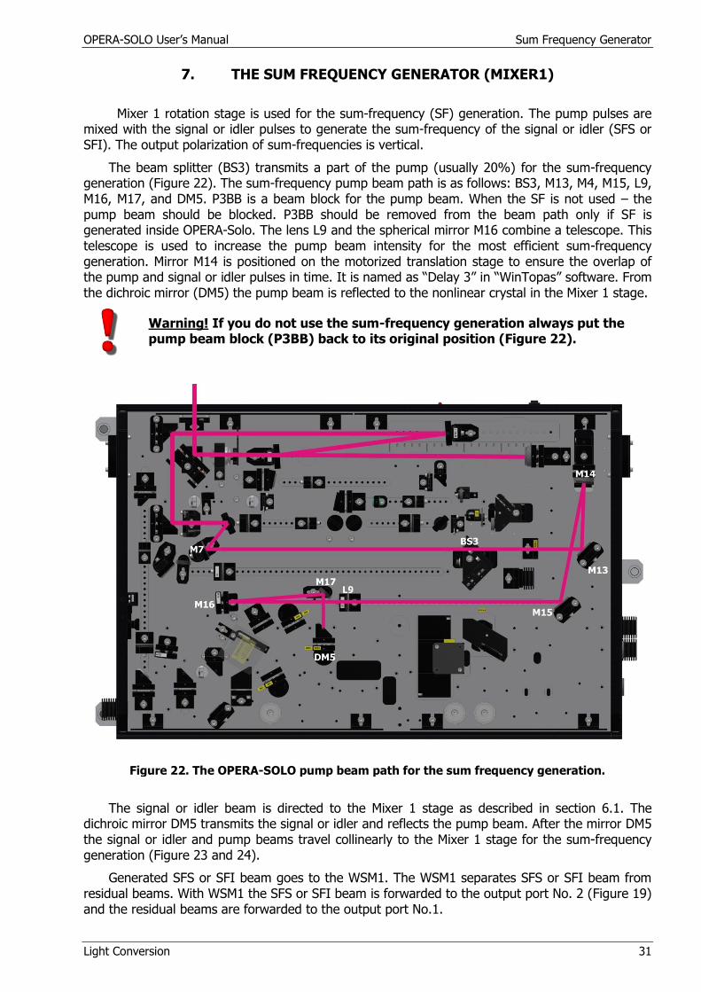
The beam splitter (BS3) transmits a part of the pump (usually 20%) for the sum-frequency generation (Figure 22). The sum-frequency pump beam path is as follows: BS3, M13, M4, M15, L9, M16, M17, and DM5. P3BB is a beam block for the pump beam. When the SF is not used – the pump beam should be blocked. P3BB should be removed from the beam path only if SF is generated inside OPERA-Solo. The lens L9 and the spherical mirror M16 combine a telescope. This telescope is used to increase the pump beam intensity for the most efficient sum-frequency generation. Mirror M14 is positioned on the motorized translation stage to ensure the overlap of the pump and signal or idler pulses in time. It is named as “Delay 3” in “WinTopas” software. From the dichroic mirror (DM5) the pump beam is reflected to the nonlinear crystal in the Mixer 1 stage.
Warning! If you do not use the sum-frequency generation always put the pump beam block (P3BB) back to its original position (Figure 22).
Figure 22. The OPERA-SOLO pump beam path for the sum frequency generation.
The signal or idler beam is directed to the Mixer 1 stage as described in section 6.1. The dichroic mirror DM5 transmits the signal or idler and reflects the pump beam. After the mirror DM5 the signal or idler and pump beams travel collinearly to the Mixer 1 stage for the sum-frequency generation (Figure 23 and 24).
Generated SFS or SFI beam goes to the WSM1. The WSM1 separates SFS or SFI beam from residual beams. With WSM1 the SFS or SFI beam is forwarded to the output port No. 2 (Figure 19) and the residual beams are forwarded to the output port No.1.

OPERA-SOLO User’s Manual Sum Frequency Generator
Light Conversion 32
Figure 23. SFS generation in OPERA-SOLO.
Figure 24. SFI generation in OPERA-SOLO.
Residual signal (or idler) and pump beams should be blocked at the output port No. 1
7.1. Setting the SFS or SFI Configuration
The following steps have to be taken for setting the SFS or SFI configuration:
Close the shutter.
Check the positions of the mirrors IM1 and IM2. They should be removed from the beam path and stored on the dedicated bases inside OPERA-SOLO for the generation of SFS and should be in the beam path for the generation of SFI.
Remove the fresh pump beam block (P3BB).
Put appropriate WSM1 behind the Mixer 1 on its magnetic base (the recommended wavelength separator is given in the Table 2).
Block residual beam by screwing the beam block provided with the OPERA-SOLO at the output port No. 1 (Figure 19).
Unscrew the beam block from the output port No.2 (Figure 19).
Remove WSM2 from the beam path, if present.
Type the required wavelength in the “WinTopas” menu window.
Open the shutter.
Adjust position of “Dealy 3” stage from “WinTopas” menu to optimize the output power of SF beam. Apply an offset if needed.
OPERA-SOLO User’s Manual Forth Harmonic Generator
Light Conversion 33
8. THE FOURTH HARMONIC GENERATOR (MIXER 2)
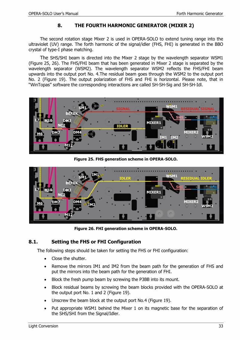
The second rotation stage Mixer 2 is used in OPERA-SOLO to extend tuning range into the ultraviolet (UV) range. The forth harmonic of the signal/idler (FHS, FHI) is generated in the BBO crystal of type-I phase matching.
The SHS/SHI beam is directed into the Mixer 2 stage by the wavelength separator WSM1
(Figure 25, 26). The FHS/FHI beam that has been generated in Mixer 2 stage is separated by the wavelength separator (WSM2). The wavelength separator WSM2 reflects the FHS/FHI beam upwards into the output port No. 4.The residual beam goes through the WSM2 to the output port No. 2 (Figure 19). The output polarization of FHS and FHI is horizontal. Please note, that in “WinTopas” software the corresponding interactions are called SH-SH-Sig and SH-SH-Idl.
Figure 25. FHS generation scheme in OPERA-SOLO.
Figure 26. FHI generation scheme in OPERA-SOLO.
8.1. Setting the FHS or FHI Configuration
The following steps should be taken for setting the FHS or FHI configuration:
Close the shutter.
Remove the mirrors IM1 and IM2 from the beam path for the generation of FHS and put the mirrors into the beam path for the generation of FHI.
Block the fresh pump beam by screwing the P3BB into its mount.
Block residual beams by screwing the beam blocks provided with the OPERA-SOLO at the output port No. 1 and 2 (Figure 19).
Unscrew the beam block at the output port No.4 (Figure 19).
Put appropriate WSM1 behind the Mixer 1 on its magnetic base for the separation of the SHS/SHI from the Signal/Idler.

OPERA-SOLO User’s Manual Forth Harmonic Generator
Light Conversion 34
Put appropriate WSM2 behind the Mixer 2 on its magnetic base for the separation of FHS/FHI beam. Please see Table 2 for the recommended separators.
Type the required wavelength in the “WinTopas” menu window.
Open the shutter.

OPERA-SOLO User’s Manual The Second Harmonic of Sum Frequency Generator
Light Conversion 35
9. THE SECOND HARMONIC OF THE SUM-FREQUENCY GENERATOR (MIXER 2)
The SFS/SFI beam is forwarded to the Mixer 2 rotation stage by the wavelength separator WSM1. If the SHSFS/SHSFI is generated in the Mixer 2 stage, the pump beam block (P3BB) must be removed for the SFS/SFI generation in Mixer 1. The wavelength separator (WSM2) should be used to separate and direct the required beam upwards to the OPERA-SOLO output (Figure 27, 28). The second harmonic of sum-frequencies exits the OPERA-SOLO through the output port No.4 while the residual beam of sum-frequency through the output port No.2. Polarization of the second harmonic of sum-frequencies is horizontal.
Figure 27. SHSFS generation scheme in OPERA-SOLO.
Figure 28. SHSFI generation scheme in OPERA-SOLO.
For the output configuration see the Table 2.
9.1. Setting the Second Harmonic of Sum-Frequency Configuration
The following steps should be taken for setting the SHSFS or SHSFI configuration:
Close the shutter.
Remove the mirrors IM1 and IM2 from the beam path for the generation of SHSFS and put the mirrors on the beam path for the generation of SHSFI.
Remove the fresh pump beam block (P3BB).
OPERA-SOLO User’s Manual The Second Harmonic of Sum Frequency Generator
Light Conversion 36
Unscrew the beam block from the output port No.4 (Figure 19).
Block residual beams by screwing the beam blocks provided with the OPERA-SOLO at the output port No. 1 and 2 (Figure 19).
Open output port No. 4 (Figure 19).
Put appropriate WSM1 behind the Mixer 1 on its magnetic base for the separation of the SFS/SFI from the Signal/Idler.
Put WSM2 behind the Mixer 2 on its magnetic base for the separation of SHSFS/SHSFI beam. Please see Table 2 for the recommended separators.
Type the required wavelength in the “WinTopas” menu window.
Open the shutter.
OPERA-SOLO User’s Manual The Difference Frequency Generator
Light Conversion 37
10. THE DIFFERENCE FREQUENCY GENERATOR (MIXER 1)
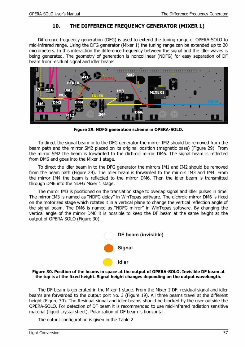
Difference frequency generation (DFG) is used to extend the tuning range of OPERA-SOLO to mid-infrared range. Using the DFG generator (Mixer 1) the tuning range can be extended up to 20 micrometers. In this interaction the difference frequency between the signal and the idler waves is being generated. The geometry of generation is noncollinear (NDFG) for easy separation of DF beam from residual signal and idler beams.
Figure 29. NDFG generation scheme in OPERA-SOLO.
To direct the signal beam in to the DFG generator the mirror IM2 should be removed from the beam path and the mirror SM2 placed on its original position (magnetic base) (Figure 29). From the mirror SM2 the beam is forwarded to the dichroic mirror DM6. The signal beam is reflected from DM6 and goes into the Mixer 1 stage.
To direct the idler beam in to the DFG generator the mirrors IM1 and IM2 should be removed from the beam path (Figure 29). The Idler beam is forwarded to the mirrors IM3 and IM4. From the mirror IM4 the beam is reflected to the mirror DM6. Then the idler beam is transmitted through DM6 into the NDFG Mixer 1 stage.
The mirror IM3 is positioned on the translation stage to overlap signal and idler pulses in time. The mirror IM3 is named as “NDFG delay” in WinTopas software. The dichroic mirror DM6 is fixed on the motorized stage which rotates it in a vertical plane to change the vertical reflection angle of the signal beam. The DM6 is named as “NDFG mirror” in WinTopas software. By changing the vertical angle of the mirror DM6 it is possible to keep the DF beam at the same height at the output of OPERA-SOLO (Figure 30).
Figure 30. Position of the beams in space at the output of OPERA-SOLO. Invisible DF beam at
the top is at the fixed height. Signal height changes depending on the output wavelength.
The DF beam is generated in the Mixer 1 stage. From the Mixer 1 DF, residual signal and idler beams are forwarded to the output port No. 3 (Figure 19). All three beams travel at the different height (Figure 30). The Residual signal and idler beams should be blocked by the user outside the OPERA-SOLO. For detection of DF beam it is recommended to use mid-infrared radiation sensitive material (liquid crystal sheet). Polarization of DF beam is horizontal.
The output configuration is given in the Table 2.
OPERA-SOLO User’s Manual The Difference Frequency Generator
Light Conversion 38
10.1. Setting the Noncolinear Difference Frequency Configuration
The following steps should be taken for setting the NDFG configuration:
Close the shutter.
Remove the idler reflecting mirrors IM1 and IM2 from the beam path.
Put the signal reflecting mirror SM2 on its magnetic base on the beam path.
Unscrew the beam block from the output port No.3 (Figure 19).
Type the required wavelength in the “WinTopas” menu window.
Open the shutter.
Adjust “NDFG delay’ motor from “WinTopas” menu for optimization of the DF output power. Apply an offset if needed.
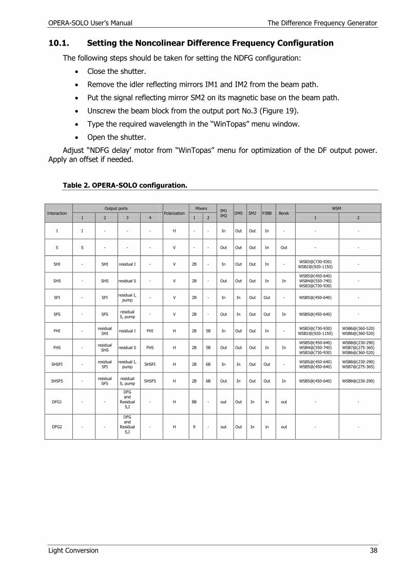
Table 2. OPERA-SOLO configuration.
Interaction Output ports
Polarization Mixers
IM1
IM2 DM5 SM2 P3BB Berek
WSM
1 2 3 4 1 2 1 2
I I - - - H - - In Out Out In - - -
S S - - - V - - Out Out Out In Out - -
SHI - SHI residual I - V 2B - In Out Out In - WSB3@(730-930)
WSB2@(920-1150) -
SHS - SHS residual S - V 2B - Out Out Out In In WSB5@(450-640) WSB4@(550-740)
WSB3@(730-930)
-
SFI - SFI residual I,
pump - V 2B - In In Out Out - WSB5@(450-640) -
SFS - SFS residual S, pump
- V 2B - Out In Out Out In WSB5@(450-640) -
FHI - residual
SHI residual I FHI H 2B 5B In Out Out In -
WSB3@(730-930)
WSB2@(920-1150)
WSB6@(360-520)
WSB6@(360-520)
FHS - residual
SHS residual S FHS H 2B 5B Out Out Out In In
WSB5@(450-640) WSB4@(550-740)
WSB3@(730-930)
WSB8@(230-290) WSB7@(275-365)
WSB6@(360-520)
SHSFI - residual
SFI residual I,
pump SHSFI H 2B 6B In In Out Out -
WSB5@(450-640) WSB5@(450-640)
WSB8@(230-290) WSB7@(275-365)
SHSFS - residual
SFS residual S, pump
SHSFS H 2B 6B Out In Out Out In WSB5@(450-640) WSB8@(230-290)
DFG1 - -
DFG and
Residual S,I
- H 8B - out Out In in out - -
DFG2 - -
DFG and
Residual
S,I
- H 9 - out Out In in out - -
OPERA-SOLO User’s Manual Troubleshooting
Light Conversion 39
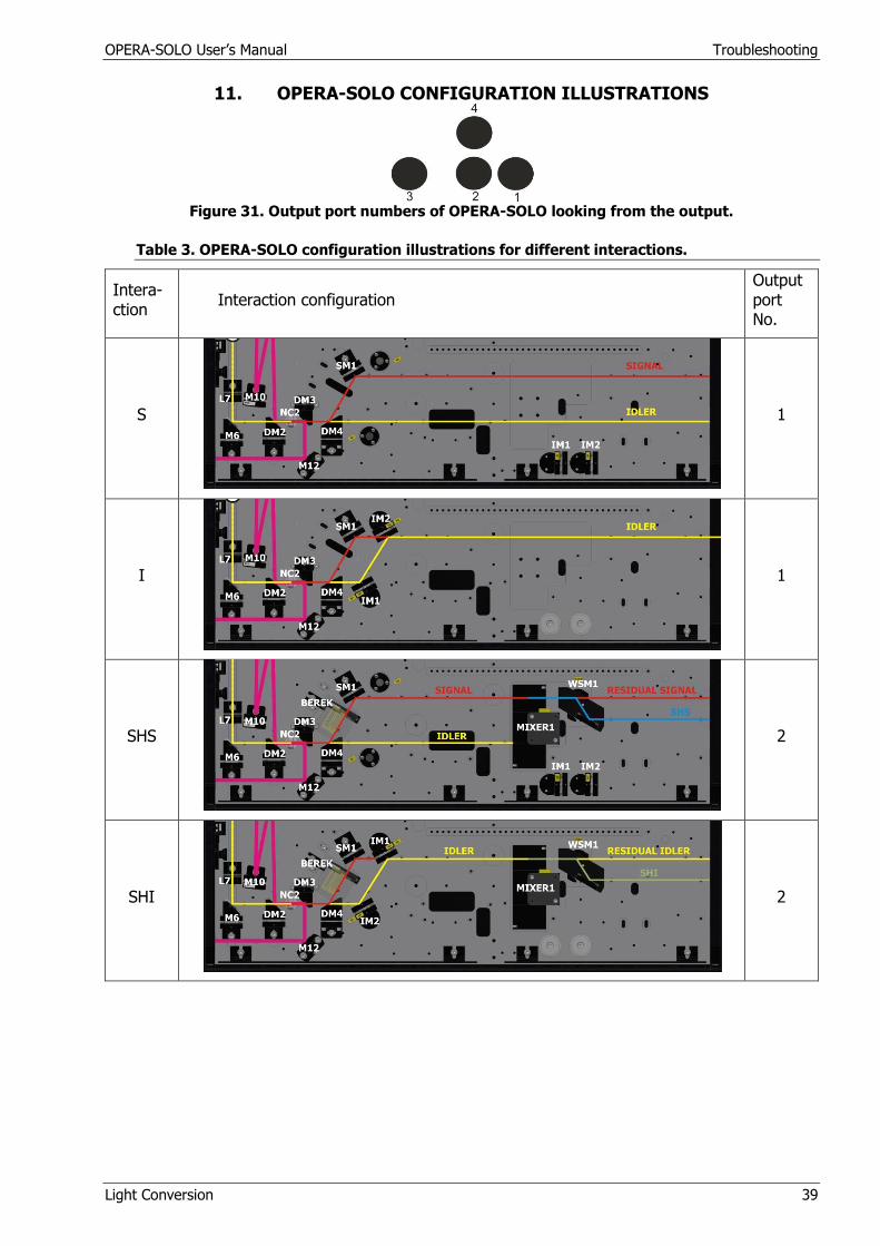
11. OPERA-SOLO CONFIGURATION ILLUSTRATIONS
Figure 31. Output port numbers of OPERA-SOLO looking from the output.
Table 3. OPERA-SOLO configuration illustrations for different interactions.
Intera-ction
Interaction configuration Output port No.
S
1
I
1
SHS
2
SHI
2

OPERA-SOLO User’s Manual Troubleshooting
Light Conversion 40
SFS
2
SFI
2
FHS
4
FHI
4
SHSFS
4
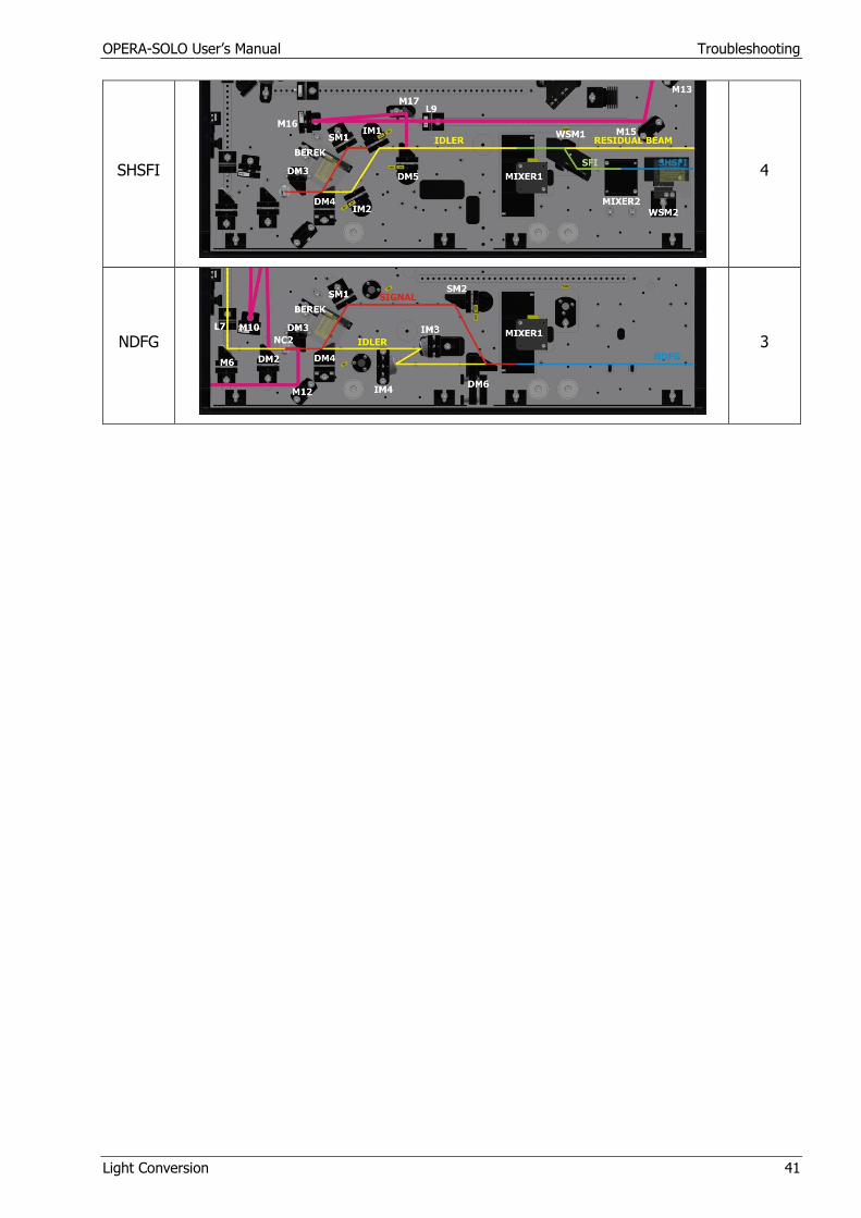
OPERA-SOLO User’s Manual Troubleshooting
Light Conversion 41
SHSFI
4
NDFG
3
OPERA-SOLO User’s Manual Troubleshooting
Light Conversion 42
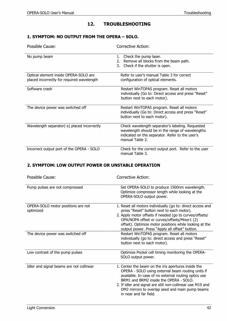
12. TROUBLESHOOTING
1. SYMPTOM: NO OUTPUT FROM THE OPERA – SOLO.
Possible Cause:
Corrective Action:
No pump beam 1. Check the pump laser. 2. Remove all blocks from the beam path.
3. Check if the shutter is open.
Optical element inside OPERA-SOLO are
placed incorrectly for required wavelength
Refer to user’s manual Table 3 for correct
configuration of optical elements.
Software crash Restart WinTOPAS program. Reset all motors
individually (Go to: Direct access and press “Reset” button next to each motor).
The device power was switched off Restart WinTOPAS program. Reset all motors individually (Go to: Direct access and press “Reset”
button next to each motor).
Wavelength separator(-s) placed incorrectly Check wavelength separator’s labeling. Requested
wavelength should be in the range of wavelengths
indicated on the separator. Refer to the user’s manual Table 2.
Incorrect output port of the OPERA - SOLO Check for the correct output port. Refer to the user manual Table 3.
2. SYMPTOM: LOW OUTPUT POWER OR UNSTABLE OPERATION
Possible Cause:
Corrective Action:
Pump pulses are not compressed Set OPERA-SOLO to produce 1500nm wavelength.
Optimize compressor length while looking at the OPERA-SOLO output power.
OPERA-SOLO motor positions are not optimized
1. Reset all motors individually (go to: direct access and press “Reset” button next to each motor).
2. Apply motor offsets if needed (go to curves/offsets/
OPA/NOPA offset or curves/offsets/Mixer1 (2) offset). Optimize motor positions while looking at the
output power. Press “Apply all offset” button.
The device power was switched off Restart WinTOPAS program. Reset all motors
individually (go to: direct access and press “Reset”
button next to each motor).
Low contrast of the pump pulses Optimize Pockel cell timing monitoring the OPERA-
SOLO output power.
Idler and signal beams are not collinear 1. Center the beam on the iris apertures inside the OPERA - SOLO using external beam routing units if
available. In case of no external routing optics use
BRM1 and BRM2 inside the OPERA - SOLO. 2. If idler and signal are still non-collinear use M10 and
DM2 mirrors to overlap seed and main pump beams in near and far field.
OPERA-SOLO User’s Manual Troubleshooting
Light Conversion 43
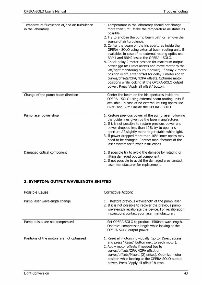
Temperature fluctuation or/and air turbulence
in the laboratory.
1. Temperature in the laboratory should not change
more than 1 ºC. Make the temperature as stable as
possible.
2. Try to enclose the pump beam path or remove the
source of air turbulence. 3. Center the beam on the iris apertures inside the
OPERA - SOLO using external beam routing units if
available. In case of no external routing optics use BRM1 and BRM2 inside the OPERA - SOLO.
4. Check delay 2 motor position for maximum output
power (go to: Direct access and move motor to the
left/right monitoring output power). If delay 2 motor position is off, enter offset for delay 2 motor (go to
curves/offsets/OPA/NOPA offset). Optimize motor positions while looking at the OPERA-SOLO output
power. Press “Apply all offset” button.
Change of the pump beam direction Center the beam on the iris apertures inside the
OPERA - SOLO using external beam routing units if available. In case of no external routing optics use
BRM1 and BRM2 inside the OPERA - SOLO.
Pump laser power drop 1. Restore previous power of the pump laser following
the guide lines given by the laser manufacturer.
2. If it is not possible to restore previous power and power dropped less than 10% try to open iris
aperture A2 slightly more to get stable white light. 3. If power dropped more than 10% inner optics may
need to be changed. Contact manufacturer of the laser system for further instructions.
Damaged optical component
1. If possible try to avoid the damage by rotating or
lifting damaged optical component.
2. If not possible to avoid the damaged area contact
laser manufacturer for replacement.
3. SYMPTOM: OUTPUT WAVELENGTH SHIFTED
Possible Cause:
Corrective Action:
Pump laser wavelength change 1. Restore previous wavelength of the pump laser
2. If it is not possible to recover the previous pump wavelength recalibrate the device. For recalibration
instructions contact your laser manufacturer.
Pump pulses are not compressed Set OPERA-SOLO to produce 1500nm wavelength.
Optimize compressor length while looking at the OPERA-SOLO output power.
Positions of the motors are not optimized 1. Reset all motors individually (go to: Direct access and press “Reset” button next to each motor).
2. Apply motor offsets if needed (go to curves/offsets/OPA/NOPA offset or
curves/offsets/Mixer1 (2) offset). Optimize motor
position while looking at the OPERA-SOLO output power. Press “Apply all offset” button.
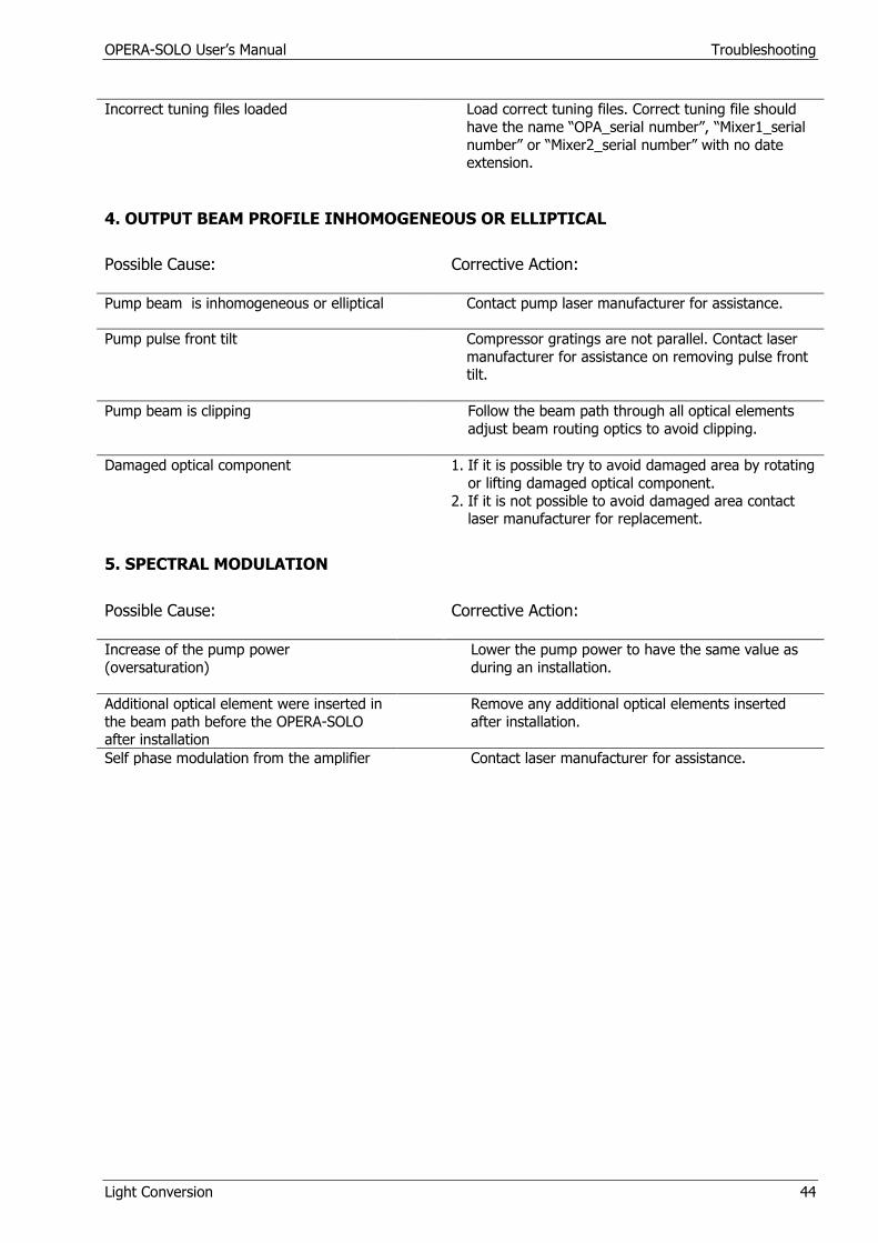
OPERA-SOLO User’s Manual Troubleshooting
Light Conversion 44
Incorrect tuning files loaded Load correct tuning files. Correct tuning file should
have the name “OPA_serial number”, “Mixer1_serial
number” or “Mixer2_serial number” with no date extension.
4. OUTPUT BEAM PROFILE INHOMOGENEOUS OR ELLIPTICAL
Possible Cause:
Corrective Action:
Pump beam is inhomogeneous or elliptical Contact pump laser manufacturer for assistance.
Pump pulse front tilt Compressor gratings are not parallel. Contact laser
manufacturer for assistance on removing pulse front tilt.
Pump beam is clipping Follow the beam path through all optical elements
adjust beam routing optics to avoid clipping.
Damaged optical component
1. If it is possible try to avoid damaged area by rotating
or lifting damaged optical component.
2. If it is not possible to avoid damaged area contact laser manufacturer for replacement.
5. SPECTRAL MODULATION
Possible Cause:
Corrective Action:
Increase of the pump power
(oversaturation)
Lower the pump power to have the same value as
during an installation.
Additional optical element were inserted in
the beam path before the OPERA-SOLO after installation
Remove any additional optical elements inserted
after installation.
Self phase modulation from the amplifier Contact laser manufacturer for assistance.
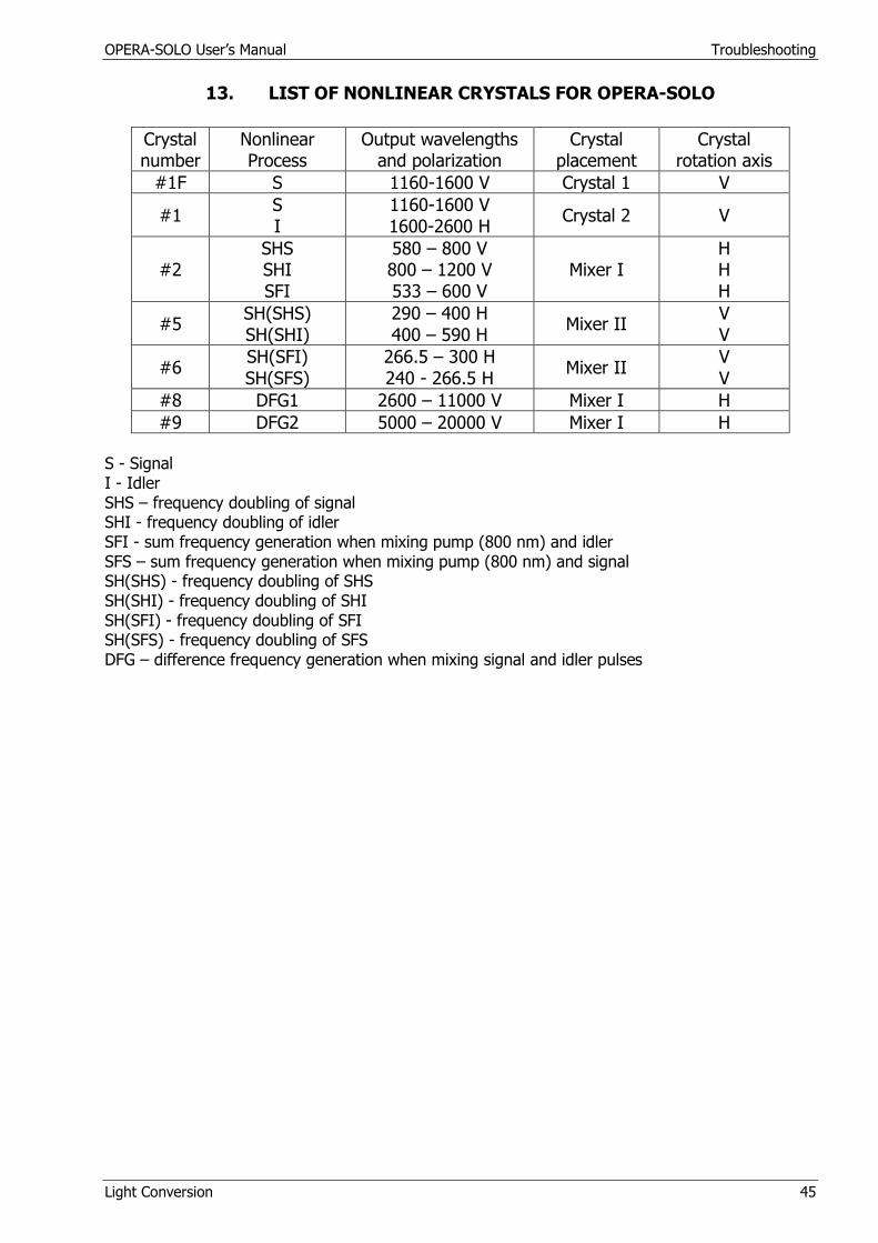
OPERA-SOLO User’s Manual Troubleshooting
Light Conversion 45
13. LIST OF NONLINEAR CRYSTALS FOR OPERA-SOLO
Crystal number
Nonlinear Process
Output wavelengths and polarization
Crystal placement
Crystal rotation axis
#1F S 1160-1600 V Crystal 1 V
#1 S I
1160-1600 V 1600-2600 H
Crystal 2 V
#2 SHS SHI SFI
580 – 800 V 800 – 1200 V 533 – 600 V
Mixer I H H H
#5 SH(SHS) SH(SHI)
290 – 400 H 400 – 590 H
Mixer II V V
#6 SH(SFI) SH(SFS)
266.5 – 300 H 240 - 266.5 H
Mixer II V V
#8 DFG1 2600 – 11000 V Mixer I H
#9 DFG2 5000 – 20000 V Mixer I H
S - Signal I - Idler SHS – frequency doubling of signal SHI - frequency doubling of idler SFI - sum frequency generation when mixing pump (800 nm) and idler SFS – sum frequency generation when mixing pump (800 nm) and signal SH(SHS) - frequency doubling of SHS SH(SHI) - frequency doubling of SHI SH(SFI) - frequency doubling of SFI SH(SFS) - frequency doubling of SFS DFG – difference frequency generation when mixing signal and idler pulses


![The Solar System’s Motion in the Galactic Tidal Field 597[3].pdfThe Solar System’s Motion in the Galactic Tidal Field ... parameters for the solar system’s motion were taken](https://img.pdfslide.us/doc/110x75/5ab63e5c7f8b9a1a048d9cc1/the-solar-systems-motion-in-the-galactic-tidal-field-5973pdfthe-solar-systems.jpg)