Embed Size (px)
Citation preview
OpenVG SpecificationVersion 1.1
Version 1.0 – August 1, 2005Version 1.0.1 – January 26, 2007Version 1.1 – December 3, 2008
Editors: Daniel Rice, Google, Inc.Robert J. Simpson, AMD
“ ”
For Ilise – DSR
Copyright © 2005-2008 The Khronos Group Inc. All Rights Reserved.
This specification is protected by copyright laws and contains material proprietary to the Khronos Group, Inc. It or any components may not be reproduced, republished, distributed, transmitted, displayed, broadcast or otherwise exploited in any manner without the express prior written permission of Khronos Group. You may use this specification for implementing the functionality therein, without altering or removing any trademark, copyright or other notice from the specification, but the receipt or possession of this specification does not convey any rights to reproduce, disclose, or distribute its contents, or to manufacture, use, or sell anything that it may describe, in whole or in part.
Khronos Group grants express permission to any current Promoter, Contributor or Adopter member of Khronos to copy and redistribute UNMODIFIED versions of this specification in any fashion, provided that NO CHARGE is made for the specification and the latest available update of the specification for any version of the API is used whenever possible. Such distributed specification may be re-formatted AS LONG AS the contents of the specification are not changed in any way. The specification may be incorporated into a product that is sold as long as such product includes significant independent work developed by the seller. A link to the current version of this specification on the Khronos Group web-site should be included whenever possible with specification distributions.
Khronos Group makes no, and expressly disclaims any, representations or warranties, express or implied, regarding this specification, including, without limitation, any implied warranties of merchantability or fitness for a particular purpose or non-infringement of any intellectual property.
Khronos Group makes no, and expressly disclaims any, warranties, express or implied regarding the correctness, accuracy, completeness, timeliness, and reliability of the specification. Under no circumstances will the Khronos Group, or any of its Promoters, Contributors or Members or their respective partners, officers, directors, employees, agents or representatives be liable for any damages, whether direct, indirect, special or consequential damages for lost revenues, lost profits, or otherwise, arising from or in connection with these materials.
Khronos and OpenVG are trademarks of The Khronos Group Inc. OpenGL is a registered trademark, and OpenGL ES is a trademark, of Silicon Graphics, Inc.
Table of Contents1Introduction..................................................................................................................................10
1.1Feature Set..........................................................................................................................101.2Target Applications..............................................................................................................10
SVG and Adobe Flash Viewers .................................................................................................10Portable Mapping Applications................................................................................................10E-book Readers............................................................................................................................11Games...........................................................................................................................................11Scalable User Interfaces.............................................................................................................11Low-Level Graphics Device Interface......................................................................................11
1.3Target Devices.....................................................................................................................111.4Design Philosophy...............................................................................................................111.5Naming and Typographical Conventions.............................................................................121.6Library Naming....................................................................................................................12
2The OpenVG Pipeline..................................................................................................................132.1Stage 1: Path, Transformation, Stroke, and Paint...............................................................142.2Stage 2: Stroked Path Generation.......................................................................................142.3Stage 3: Transformation......................................................................................................142.4Stage 4: Rasterization.........................................................................................................142.5Stage 5: Clipping and Masking............................................................................................152.6Stage 6: Paint Generation...................................................................................................152.7Stage 7: Image Interpolation...............................................................................................152.8Stage 8: Color Transformation, Blending, and Antialiasing..................................................162.9Multisampling......................................................................................................................16
3Constants, Functions and Data Types.........................................................................................163.1Versioning............................................................................................................................17
OPENVG_VERSION_1_1..........................................................................................................173.2Primitive Data Types............................................................................................................17
VGbyte..........................................................................................................................................17VGubyte.......................................................................................................................................17VGshort........................................................................................................................................17VGint.............................................................................................................................................18VGuint..........................................................................................................................................18VGbitfield.....................................................................................................................................18VGboolean...................................................................................................................................18VGfloat.........................................................................................................................................18
3.3Floating-Point and Integer Representations........................................................................18VG_MAXSHORT........................................................................................................................19VG_MAXINT...............................................................................................................................19VG_MAX_FLOAT.......................................................................................................................19
3.4Colors..................................................................................................................................193.4.1Linear and Non-Linear Color Representations............................................................20
i
3.4.2Color Space Definitions...............................................................................................213.4.3Premultiplied Alpha......................................................................................................233.4.4Color Format Conversion............................................................................................23
3.5Enumerated Data Types......................................................................................................243.6Handle-based Data Types...................................................................................................25
VGHandle....................................................................................................................................25VG_INVALID_HANDLE..........................................................................................................26
4The Drawing Context...................................................................................................................274.1Errors..................................................................................................................................29
VGErrorCode...............................................................................................................................29vgGetError...................................................................................................................................30
4.2Manipulating the Context Using EGL ..................................................................................304.2.1EGLConfig Attributes...................................................................................................30
EGL_OPENVG_BIT....................................................................................................................30EGL_ALPHA_MASK_SIZE.......................................................................................................31
4.2.2EGL Functions.............................................................................................................31eglBindAPI...................................................................................................................................31eglCreateContext.........................................................................................................................31eglCreateWindowSurface..........................................................................................................31eglCreatePbufferFromClientBuffer..........................................................................................32eglMakeCurrent..........................................................................................................................32eglGetCurrentContext................................................................................................................32eglDestroyContext......................................................................................................................32eglSwapBuffers............................................................................................................................32
4.3Forcing Drawing to Complete..............................................................................................33vgFlush.........................................................................................................................................33vgFinish........................................................................................................................................33
5Setting API Parameters...............................................................................................................345.1Context Parameter Types....................................................................................................34
VGParamType.............................................................................................................................345.2Setting and Querying Context Parameter Values................................................................36
vgSet..............................................................................................................................................36vgGet and vgGetVectorSize .......................................................................................................37
5.2.1Default Context Parameter Values..............................................................................385.3Setting and Querying Object Parameter Values..................................................................40
vgSetParameter...........................................................................................................................40vgGetParameter and vgGetParameterVectorSize ..................................................................41
6Rendering Quality and Antialiasing..............................................................................................446.1Rendering Quality................................................................................................................45
VGRenderingQuality.................................................................................................................456.2Additional Quality Settings...................................................................................................46
VGPixelLayout............................................................................................................................466.3Coordinate Systems and Transformations...........................................................................476.4Coordinate Systems............................................................................................................476.5Transformations...................................................................................................................48
ii
6.5.1Homogeneous Coordinates.........................................................................................486.5.2Affine Transformations.................................................................................................496.5.3Projective (Perspective) Transformations....................................................................49
6.6Matrix Manipulation.............................................................................................................50VGMatrixMode...........................................................................................................................51vgLoadIdentity............................................................................................................................51vgLoadMatrix..............................................................................................................................51vgGetMatrix.................................................................................................................................52.......................................................................................................................................................52vgMultMatrix..............................................................................................................................53vgTranslate...................................................................................................................................53vgScale..........................................................................................................................................54vgShear.........................................................................................................................................54vgRotate.......................................................................................................................................54
7Scissoring, Masking, and Clearing..............................................................................................557.1Scissoring............................................................................................................................55
VG_MAX_SCISSOR_RECTS.....................................................................................................55Specifying Scissoring Rectangles..............................................................................................55
7.2Masking ..............................................................................................................................56VGMaskOperation......................................................................................................................57vgMask.........................................................................................................................................58vgRenderToMask........................................................................................................................60VGMaskLayer..............................................................................................................................61vgCreateMaskLayer...................................................................................................................61vgDestroyMaskLayer.................................................................................................................62vgFillMaskLayer.........................................................................................................................62vgCopyMask...............................................................................................................................63
7.3Fast Clearing.......................................................................................................................64vgClear.........................................................................................................................................64
8Paths...........................................................................................................................................648.1Moves..................................................................................................................................658.2Straight Line Segments.......................................................................................................658.3Bézier Curves......................................................................................................................65
8.3.1Quadratic Bézier Curves.............................................................................................658.3.2Cubic Bézier Curves....................................................................................................668.3.3G1 Smooth Segments.................................................................................................668.3.4C1 Smooth Segments.................................................................................................678.3.5C2 Smooth Segments.................................................................................................688.3.6Converting Segments From Quadratic to Cubic Form.................................................68
8.4Elliptical Arcs.......................................................................................................................688.5The Standard Path Format..................................................................................................69
VG_PATH_FORMAT_STANDARD.........................................................................................708.5.1Path Segment Command Side Effects........................................................................708.5.2Segment Commands...................................................................................................718.5.3Coordinate Data Formats............................................................................................73
iii
VGPathDatatype.........................................................................................................................748.5.4Segment Type Marker Definitions...............................................................................74
VGPathAbsRel.............................................................................................................................75VGPathSegment..........................................................................................................................75VGPathCommand.......................................................................................................................75
8.5.5Path Example..............................................................................................................768.6Path Operations..................................................................................................................77
8.6.1Storage of Paths..........................................................................................................78VGPath.........................................................................................................................................79
8.6.2Creating and Destroying Paths....................................................................................79VGPathCapabilities....................................................................................................................79vgCreatePath...............................................................................................................................80vgClearPath.................................................................................................................................82vgDestroyPath.............................................................................................................................82
8.6.3Path Queries...............................................................................................................82VGPathParamType.....................................................................................................................82Path Format..................................................................................................................................83Path Datatype..............................................................................................................................83Path Scale.....................................................................................................................................84Path Bias.......................................................................................................................................84Number of Segments..................................................................................................................84Number of Coordinates.............................................................................................................84
8.6.4Querying and Modifying Path Capabilities...................................................................84vgGetPathCapabilities................................................................................................................84vgRemovePathCapabilities.......................................................................................................85
8.6.5Copying Data Between Paths......................................................................................85vgAppendPath............................................................................................................................85
8.6.6Appending Data to a Path...........................................................................................86vgAppendPathData....................................................................................................................86
8.6.7Modifying Path Data....................................................................................................87vgModifyPathCoords.................................................................................................................87
8.6.8Transforming a Path....................................................................................................88vgTransformPath.........................................................................................................................88
8.6.9Interpolating Between Paths........................................................................................89vgInterpolatePath.......................................................................................................................90
8.6.10Length of a Path........................................................................................................91vgPathLength..............................................................................................................................91
8.6.11Position and Tangent Along a Path............................................................................92The Tangents of a Path Segment...............................................................................................92vgPointAlongPath.......................................................................................................................93
8.6.12Querying the Bounding Box of a Path.......................................................................95vgPathBounds.............................................................................................................................96vgPathTransformedBounds.......................................................................................................96
8.7Interpretation of Paths.........................................................................................................978.7.1Filling Paths.................................................................................................................97
iv
Creating Holes in Paths..............................................................................................................98Implicit Closure of Filled Subpaths........................................................................................100
8.7.2Stroking Paths...........................................................................................................1018.7.3Stroke Parameters.....................................................................................................102
End Cap Styles..........................................................................................................................102Line Join Styles..........................................................................................................................103Miter Length..............................................................................................................................104Dashing......................................................................................................................................104
8.7.4Stroke Generation.....................................................................................................1068.7.5Setting Stroke Parameters.........................................................................................107
VGCapStyle...............................................................................................................................107VGJoinStyle................................................................................................................................108VG_MAX_DASH_COUNT.....................................................................................................108Setting the Dash Pattern...........................................................................................................109
8.7.6Non-Scaling Strokes..................................................................................................1098.8Filling or Stroking a Path....................................................................................................110
VGFillRule..................................................................................................................................110VGPaintMode............................................................................................................................111vgDrawPath...............................................................................................................................111Filling a Path..............................................................................................................................111Stroking a Path..........................................................................................................................112Filling and Stroking a Path......................................................................................................113
9Paint..........................................................................................................................................1149.1Paint Definitions.................................................................................................................114
VGPaint......................................................................................................................................1149.1.1Creating and Destroying Paint Objects......................................................................115
vgCreatePaint............................................................................................................................115vgDestroyPaint..........................................................................................................................115
9.1.2Setting the Current Paint...........................................................................................115vgSetPaint..................................................................................................................................115vgGetPaint.................................................................................................................................117
9.1.3Setting Paint Parameters...........................................................................................117VGPaintParamType..................................................................................................................117VGPaintType..............................................................................................................................119
9.2Color Paint.........................................................................................................................119Setting Color Paint Parameters...............................................................................................119vgSetColor..................................................................................................................................120vgGetColor.................................................................................................................................121
9.3Gradient Paint....................................................................................................................1229.3.1Linear Gradients........................................................................................................122
Setting Linear Gradient Parameters.......................................................................................1239.3.2Radial Gradients........................................................................................................123
Setting Radial Gradient Parameters.......................................................................................1259.3.3Color Ramps..............................................................................................................126
VG_MAX_COLOR_RAMP_STOPS.......................................................................................127
v
VGColorRampSpreadMode....................................................................................................127Setting Color Ramp Parameters..............................................................................................128Formal Definition of Spread Modes.......................................................................................129
9.3.4Gradient Examples....................................................................................................1309.4Pattern Paint......................................................................................................................131
vgPaintPattern...........................................................................................................................1329.4.1Pattern Tiling..............................................................................................................132
VGTilingMode...........................................................................................................................133Setting the Pattern Tiling Mode..............................................................................................133
10Images.....................................................................................................................................13510.1Image Coordinate Systems.............................................................................................13510.2Image Formats................................................................................................................135
VGImageFormat........................................................................................................................13510.3Creating and Destroying Images.....................................................................................139
VGImage....................................................................................................................................139VGImageQuality.......................................................................................................................139VG_MAX_IMAGE_WIDTH....................................................................................................140VG_MAX_IMAGE_HEIGHT..................................................................................................140VG_MAX_IMAGE_PIXELS.....................................................................................................140VG_MAX_IMAGE_BYTES......................................................................................................140vgCreateImage..........................................................................................................................141vgDestroyImage........................................................................................................................142
10.4Querying Images.............................................................................................................142VGImageParamType................................................................................................................142Image Format............................................................................................................................142Image Width..............................................................................................................................143Image Height.............................................................................................................................143
10.5Reading and Writing Image Pixels...................................................................................143vgClearImage............................................................................................................................143vgImageSubData.......................................................................................................................144vgGetImageSubData................................................................................................................145
10.6Child Images....................................................................................................................146vgChildImage............................................................................................................................147vgGetParent...............................................................................................................................148
10.7Copying Pixels Between Images.....................................................................................148vgCopyImage............................................................................................................................148
10.8Drawing Images to the Drawing Surface.........................................................................149VGImageMode..........................................................................................................................149vgDrawImage............................................................................................................................150VG_DRAW_IMAGE_NORMAL.............................................................................................151VG_DRAW_IMAGE_MULTIPLY...........................................................................................151VG_DRAW_IMAGE_STENCIL..............................................................................................152
10.9Reading and Writing Drawing Surface Pixels..................................................................15310.9.1Writing Drawing Surface Pixels...............................................................................154
vgSetPixels.................................................................................................................................154
vi
vgWritePixels.............................................................................................................................15410.9.2Reading Drawing Surface Pixels.............................................................................156
vgGetPixels................................................................................................................................156vgReadPixels.............................................................................................................................156
10.10Copying Portions of the Drawing Surface......................................................................158vgCopyPixels.............................................................................................................................158
11Text..........................................................................................................................................16011.1Text Rendering.................................................................................................................16011.2Font Terminology.............................................................................................................16111.3Glyph Positioning and Text Layout...................................................................................16111.4Fonts in OpenVG.............................................................................................................164
11.4.1VGFont Objects and Glyph Mapping.......................................................................164VGFont.......................................................................................................................................164Glyph Mapping.........................................................................................................................164
11.4.2Managing VGFont Objects .......................................................................................165vgCreateFont.............................................................................................................................165vgDestroyFont...........................................................................................................................166
11.4.3Querying VGFont Objects ........................................................................................166VGFontParamType ..................................................................................................................166Number of Glyphs....................................................................................................................167
11.4.4Adding and Modifying Glyphs in VGFonts...............................................................167vgSetGlyphToPath....................................................................................................................168vgSetGlyphToImage.................................................................................................................169vgClearGlyph............................................................................................................................170
11.4.5Font Sharing............................................................................................................17011.5Text Layout and Rendering..............................................................................................171
vgDrawGlyph............................................................................................................................171vgDrawGlyphs..........................................................................................................................172
12Image Filters............................................................................................................................17412.1Format Normalization......................................................................................................17412.2Channel Masks................................................................................................................175
VGImageChannel.....................................................................................................................17512.3Color Combination...........................................................................................................176
vgColorMatrix...........................................................................................................................17612.4Convolution......................................................................................................................177
VG_MAX_KERNEL_SIZE.......................................................................................................177VG_MAX_SEPARABLE_KERNEL_SIZE..............................................................................177VG_MAX_GAUSSIAN_STD_DEVIATION..........................................................................178vgConvolve................................................................................................................................178vgSeparableConvolve...............................................................................................................180vgGaussianBlur.........................................................................................................................181
12.5Lookup Tables.................................................................................................................183vgLookup...................................................................................................................................183vgLookupSingle........................................................................................................................184
13Color Transformation and Blending.........................................................................................185
vii
13.1Color Transformation.......................................................................................................185Setting the Color Transformation...........................................................................................186
13.2Blending Equations..........................................................................................................18613.3Porter-Duff Blending........................................................................................................18713.4Additional Blending Modes..............................................................................................18813.5Additive Blending.............................................................................................................18913.6Setting the Blend Mode...................................................................................................189
VGBlendMode...........................................................................................................................18914Querying Hardware Capabilities..............................................................................................191
VGHardwareQueryType.........................................................................................................191VGHardwareQueryResult.......................................................................................................191vgHardwareQuery...................................................................................................................191
15Extending the API....................................................................................................................19315.1Extension Naming Conventions.......................................................................................19315.2The Extension Registry....................................................................................................19315.3Using Extensions.............................................................................................................193
15.3.1Accessing Extensions Statically..............................................................................19415.3.2Accessing Extensions Dynamically.........................................................................194
VGStringID................................................................................................................................194vgGetString................................................................................................................................194eglGetProcAddress...................................................................................................................195
15.4Creating Extensions........................................................................................................19516API Conformance....................................................................................................................196
16.1Conformance Test Principles...........................................................................................19616.1.1Window System Independence...............................................................................19616.1.2Antialiasing Algorithm Independence.......................................................................19616.1.3On-Device and Off-Device Testing...........................................................................196
16.2Types of Conformance Tests...........................................................................................19716.2.1Pipeline Tests..........................................................................................................19716.2.2Self-Consistency Tests............................................................................................19716.2.3Matrix Tests.............................................................................................................19716.2.4Interior/Exterior Tests...............................................................................................19716.2.5Positional Invariance...............................................................................................19716.2.6Image Comparison Tests.........................................................................................197
17The VGU Utility Library............................................................................................................199VGU_VERSION_1_1................................................................................................................199VGUErrorCode..........................................................................................................................199
17.1Higher-level Geometric Primitives...................................................................................20017.1.1Lines........................................................................................................................200
vguLine.......................................................................................................................................20017.1.2Polylines and Polygons...........................................................................................200
vguPolygon................................................................................................................................20017.1.3Rectangles...............................................................................................................201
vguRect.......................................................................................................................................20117.1.4Round-Cornered Rectangles...................................................................................202
viii
vguRoundRect...........................................................................................................................20217.1.5Ellipses....................................................................................................................204
vguEllipse..................................................................................................................................20417.1.6Arcs.........................................................................................................................205
VGUArcType.............................................................................................................................205vguArc........................................................................................................................................206
17.2Image Warping................................................................................................................207vguComputeWarpQuadToSquare..........................................................................................208vguComputeWarpSquareToQuad..........................................................................................208vguComputeWarpQuadToQuad............................................................................................209
18Appendix A: Mathematics of Ellipses.......................................................................................21018.1The Center Parameterization...........................................................................................21018.2The Endpoint Parameterization.......................................................................................21118.3Converting from Center to Endpoint Parameterization....................................................21218.4Converting from Endpoint to Center Parameterization....................................................21218.5Implicit Representation of an Ellipse ................................................................................21518.6Transformation of Ellipses...............................................................................................216
19Appendix B: Header Files........................................................................................................218openvg.h.....................................................................................................................................218vgu.h...........................................................................................................................................232
20Bibliography.............................................................................................................................23521Document History....................................................................................................................23622Acknowledgments...................................................................................................................23823Indices.....................................................................................................................................240
Index of Tables...........................................................................................................................240Index of Figures........................................................................................................................240
ix
Introduction 10
1 IntroductionOpenVG is an application programming interface (API) for hardware-accelerated two-dimensional vector and raster graphics developed under the auspices of the Khronos Group (www.khronos.org). It provides a device-independent and vendor-neutral interface for sophisticated 2D graphical applications, while allowing device manufacturers to provide hardware acceleration where appropriate.
This document defines the C language binding to OpenVG. Other language bindings may be defined by Khronos in the future. We use the term “implementation” to refer to the software and/or hardware that implements OpenVG functionality, and the term “application” to refer to any software that makes use of OpenVG.
1.1 Feature SetOpenVG provides a drawing model similar to those of existing two-dimensional drawing APIs and formats, such as Adobe PostScript [ADOB99], PDF [ADOB06a], Adobe (formerly MacroMedia) Flash [ADOB06b]; Sun Microsystems Java2D [SUN04]; and W3C SVG [SVGF05][SVGT06]. Version 1.1 is specifically intended to support all drawing features required by a SVG Tiny 1.2 renderer or an Adobe Flash Lite renderer (implementing the Flash 7 feature set), and additionally to support functions that may be of use for implementing an SVG Basic renderer.
1.2 Target ApplicationsSeveral classes of target applications were used to define requirements for the design of the OpenVG API.
SVG and Adobe Flash ViewersOpenVG must provide the drawing functionality required for a high-performance SVG document viewer that is conformant with version 1.2 of the SVG Tiny profile. It does not need to provide a one-to-one mapping between SVG syntactic features and API calls, but it must provide efficient ways of implementing all SVG Tiny features.
Adobe Flash version 7 must also be supported with high performance and full compliance.
Portable Mapping ApplicationsOpenVG can provide dynamic features for map display that would be difficult or impossible to do with an SVG or Flash viewer alone, such as dynamic placement and sizing of street names and markers, and efficient viewport culling.
Version 1.1 Revision 1 (December 3, 2008)
Introduction 11
E-book ReadersThe OpenVG API must provide fast rendering of readable text in Western, Asian, and other scripts. It does not need to provide advanced text layout features. Font hinting and efficient glyph rendering must be supported by the API.
GamesThe OpenVG API must be useful for defining sprites, backgrounds, and textures for use in both 2D and 3D games. It must be able to provide two-dimensional overlays (e.g., for maps or scores) on top of 3D content.
Scalable User InterfacesOpenVG may be used to render scalable user interfaces, particularly for applications that wish to present users with a unique look and feel that is consistent across different screen resolutions.
Low-Level Graphics Device InterfaceOpenVG may be used as a low-level graphics device interface. Other graphical toolkits, such as windowing systems, may be implemented above OpenVG.
1.3 Target DevicesOpenVG is designed to run on devices ranging from wrist watches to full microprocessor-based desktop and server machines. Over time, it is expected that OpenGL ES hardware manufacturers will be able to provide inexpensive incremental acceleration for OpenVG functionality.
Realistically, to obtain the full benefit of OpenVG, a device should provide a display with at least 128 x 128 non-indexed RGB color pixels with 4 or more bits per channel.
1.4 Design PhilosophyOpenVG is intended to provide a hardware abstraction layer that will allow accelerated performance on a variety of application platforms. Functions that are not expected to be amenable to hardware acceleration in the near future were either not included, or included as part of the optional VGU utility library.
Where possible, the syntax of OpenVG is intended to be reminiscent of that of OpenGL, in order to make learning OpenVG as easy as possible for OpenGL developers. Most of the OpenVG state is encapsulated in a set of primitive-valued variables that are manipulated using the vgSet and vgGet functions. Extensions may add new state
Version 1.1 Revision 1 (December 3, 2008)
Introduction 12
variables in order to add new features to the pipeline without needing to add new functions.
Paint, path, and image objects in OpenVG are referenced using opaque handles. This allows implementations to store such objects using their own preferred representation, in whatever form of memory they choose. This is intended to simplify hardware design, and to minimize processing and bus traffic for frequently-used objects.
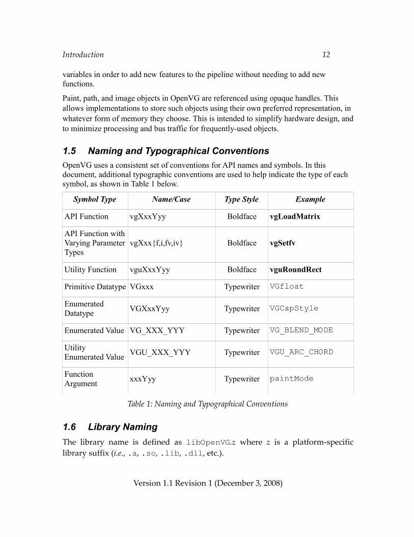
1.5 Naming and Typographical ConventionsOpenVG uses a consistent set of conventions for API names and symbols. In this document, additional typographic conventions are used to help indicate the type of each symbol, as shown in Table 1 below.
Symbol Type Name/Case Type Style Example
API Function vgXxxYyy Boldface vgLoadMatrix
API Function with Varying Parameter Types
vgXxx{f,i,fv,iv} Boldface vgSetfv
Utility Function vguXxxYyy Boldface vguRoundRect
Primitive Datatype VGxxx Typewriter VGfloat
Enumerated Datatype VGXxxYyy Typewriter VGCapStyle
Enumerated Value VG_XXX_YYY Typewriter VG_BLEND_MODE
Utility Enumerated Value VGU_XXX_YYY Typewriter VGU_ARC_CHORD
Function Argument xxxYyy Typewriter paintMode
Table 1: Naming and Typographical Conventions
1.6 Library NamingThe library name is defined as libOpenVG.z where z is a platform-specific library suffix (i.e., .a, .so, .lib, .dll, etc.).
Version 1.1 Revision 1 (December 3, 2008)
The OpenVG Pipeline 13
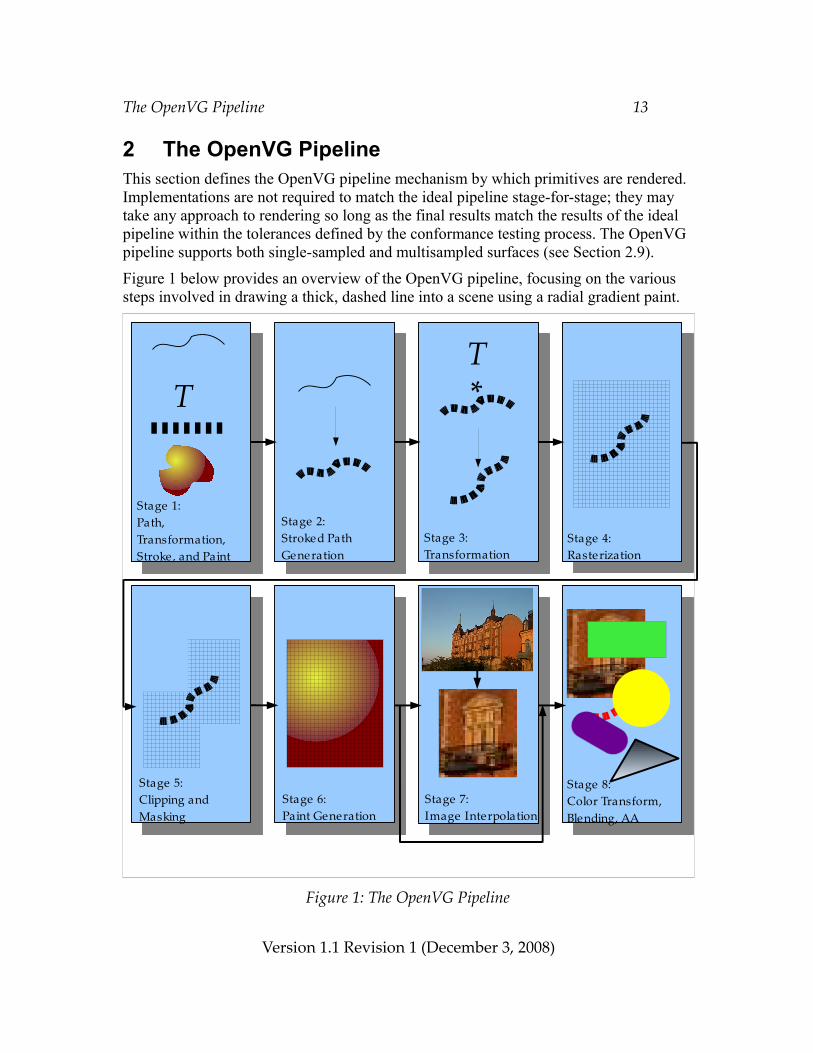
2 The OpenVG PipelineThis section defines the OpenVG pipeline mechanism by which primitives are rendered. Implementations are not required to match the ideal pipeline stage-for-stage; they may take any approach to rendering so long as the final results match the results of the ideal pipeline within the tolerances defined by the conformance testing process. The OpenVG pipeline supports both single-sampled and multisampled surfaces (see Section 2.9).
Figure 1 below provides an overview of the OpenVG pipeline, focusing on the various steps involved in drawing a thick, dashed line into a scene using a radial gradient paint.
Figure 1: The OpenVG Pipeline
Version 1.1 Revision 1 (December 3, 2008)
*
Stage 1:Path,Transformation, Stroke, and Paint
Stage 2:Stroked Path Generation
Stage 3: Transformation
Stage 4:Rasterization
Stage 6:Paint Generation
Stage 5:Clipping and Masking
Stage 8:Color Transform,Blending, AA
Stage 7:Image Interpolation
TT
The OpenVG Pipeline 14
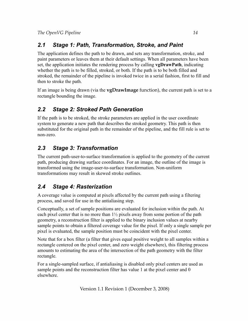
2.1 Stage 1: Path, Transformation, Stroke, and PaintThe application defines the path to be drawn, and sets any transformation, stroke, and paint parameters or leaves them at their default settings. When all parameters have been set, the application initiates the rendering process by calling vgDrawPath, indicating whether the path is to be filled, stroked, or both. If the path is to be both filled and stroked, the remainder of the pipeline is invoked twice in a serial fashion, first to fill and then to stroke the path.
If an image is being drawn (via the vgDrawImage function), the current path is set to a rectangle bounding the image.
2.2 Stage 2: Stroked Path GenerationIf the path is to be stroked, the stroke parameters are applied in the user coordinate system to generate a new path that describes the stroked geometry. This path is then substituted for the original path in the remainder of the pipeline, and the fill rule is set to non-zero.
2.3 Stage 3: TransformationThe current path-user-to-surface transformation is applied to the geometry of the current path, producing drawing surface coordinates. For an image, the outline of the image is transformed using the image-user-to-surface transformation. Non-uniform transformations may result in skewed stroke outlines.
2.4 Stage 4: RasterizationA coverage value is computed at pixels affected by the current path using a filtering process, and saved for use in the antialiasing step.
Conceptually, a set of sample positions are evaluated for inclusion within the path. At each pixel center that is no more than 1½ pixels away from some portion of the path geometry, a reconstruction filter is applied to the binary inclusion values at nearby sample points to obtain a filtered coverage value for the pixel. If only a single sample per pixel is evaluated, the sample position must be coincident with the pixel center.
Note that for a box filter (a filter that gives equal positive weight to all samples within a rectangle centered on the pixel center, and zero weight elsewhere), this filtering process amounts to estimating the area of the intersection of the path geometry with the filter rectangle.
For a single-sampled surface, if antialiasing is disabled only pixel centers are used as sample points and the reconstruction filter has value 1 at the pixel center and 0 elsewhere.
Version 1.1 Revision 1 (December 3, 2008)
The OpenVG Pipeline 15
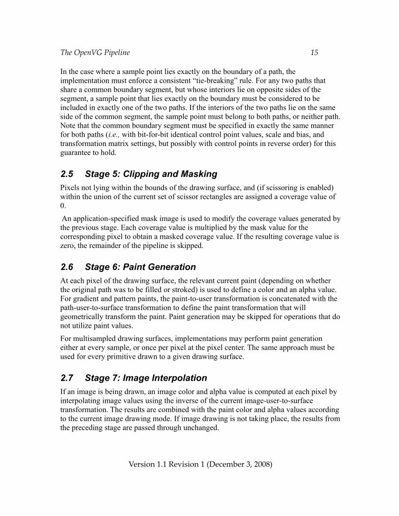
In the case where a sample point lies exactly on the boundary of a path, the implementation must enforce a consistent “tie-breaking” rule. For any two paths that share a common boundary segment, but whose interiors lie on opposite sides of the segment, a sample point that lies exactly on the boundary must be considered to be included in exactly one of the two paths. If the interiors of the two paths lie on the same side of the common segment, the sample point must belong to both paths, or neither path. Note that the common boundary segment must be specified in exactly the same manner for both paths (i.e., with bit-for-bit identical control point values, scale and bias, and transformation matrix settings, but possibly with control points in reverse order) for this guarantee to hold.
2.5 Stage 5: Clipping and MaskingPixels not lying within the bounds of the drawing surface, and (if scissoring is enabled) within the union of the current set of scissor rectangles are assigned a coverage value of 0.
An application-specified mask image is used to modify the coverage values generated by the previous stage. Each coverage value is multiplied by the mask value for the corresponding pixel to obtain a masked coverage value. If the resulting coverage value is zero, the remainder of the pipeline is skipped.
2.6 Stage 6: Paint GenerationAt each pixel of the drawing surface, the relevant current paint (depending on whether the original path was to be filled or stroked) is used to define a color and an alpha value. For gradient and pattern paints, the paint-to-user transformation is concatenated with the path-user-to-surface transformation to define the paint transformation that will geometrically transform the paint. Paint generation may be skipped for operations that do not utilize paint values.
For multisampled drawing surfaces, implementations may perform paint generation either at every sample, or once per pixel at the pixel center. The same approach must be used for every primitive drawn to a given drawing surface.
2.7 Stage 7: Image InterpolationIf an image is being drawn, an image color and alpha value is computed at each pixel by interpolating image values using the inverse of the current image-user-to-surface transformation. The results are combined with the paint color and alpha values according to the current image drawing mode. If image drawing is not taking place, the results from the preceding stage are passed through unchanged.
Version 1.1 Revision 1 (December 3, 2008)
The OpenVG Pipeline 16
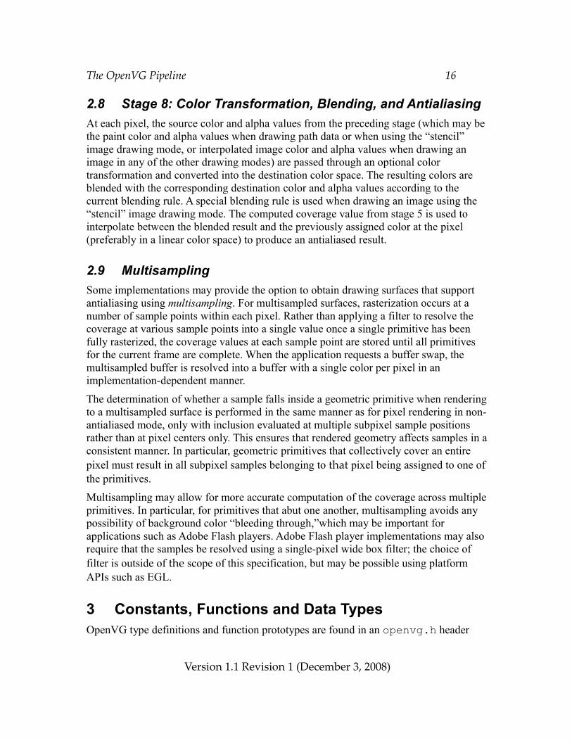
2.8 Stage 8: Color Transformation, Blending, and AntialiasingAt each pixel, the source color and alpha values from the preceding stage (which may be the paint color and alpha values when drawing path data or when using the “stencil” image drawing mode, or interpolated image color and alpha values when drawing an image in any of the other drawing modes) are passed through an optional color transformation and converted into the destination color space. The resulting colors are blended with the corresponding destination color and alpha values according to the current blending rule. A special blending rule is used when drawing an image using the “stencil” image drawing mode. The computed coverage value from stage 5 is used to interpolate between the blended result and the previously assigned color at the pixel (preferably in a linear color space) to produce an antialiased result.
2.9 MultisamplingSome implementations may provide the option to obtain drawing surfaces that support antialiasing using multisampling. For multisampled surfaces, rasterization occurs at a number of sample points within each pixel. Rather than applying a filter to resolve the coverage at various sample points into a single value once a single primitive has been fully rasterized, the coverage values at each sample point are stored until all primitives for the current frame are complete. When the application requests a buffer swap, the multisampled buffer is resolved into a buffer with a single color per pixel in an implementation-dependent manner.
The determination of whether a sample falls inside a geometric primitive when rendering to a multisampled surface is performed in the same manner as for pixel rendering in non-antialiased mode, only with inclusion evaluated at multiple subpixel sample positions rather than at pixel centers only. This ensures that rendered geometry affects samples in a consistent manner. In particular, geometric primitives that collectively cover an entire pixel must result in all subpixel samples belonging to that pixel being assigned to one of the primitives.
Multisampling may allow for more accurate computation of the coverage across multiple primitives. In particular, for primitives that abut one another, multisampling avoids any possibility of background color “bleeding through,”which may be important for applications such as Adobe Flash players. Adobe Flash player implementations may also require that the samples be resolved using a single-pixel wide box filter; the choice of filter is outside of the scope of this specification, but may be possible using platform APIs such as EGL.
3 Constants, Functions and Data TypesOpenVG type definitions and function prototypes are found in an openvg.h header
Version 1.1 Revision 1 (December 3, 2008)
Constants, Functions and Data Types 17
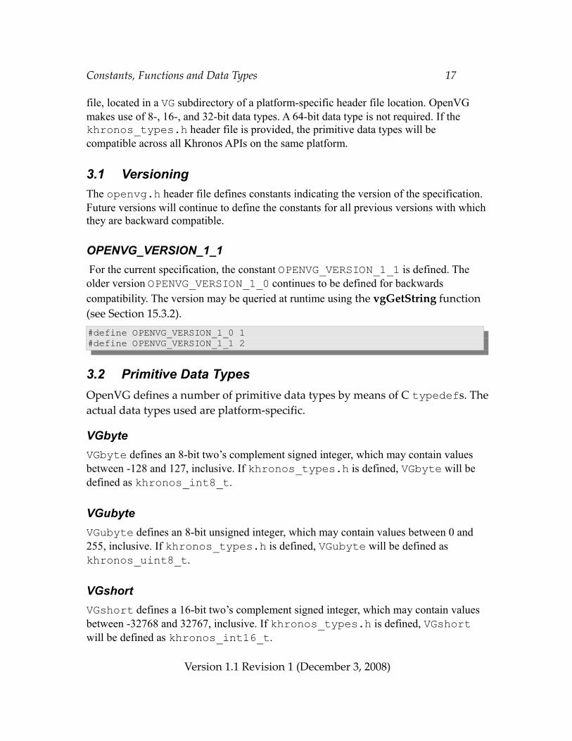
file, located in a VG subdirectory of a platform-specific header file location. OpenVG makes use of 8-, 16-, and 32-bit data types. A 64-bit data type is not required. If the khronos_types.h header file is provided, the primitive data types will be compatible across all Khronos APIs on the same platform.
3.1 VersioningThe openvg.h header file defines constants indicating the version of the specification. Future versions will continue to define the constants for all previous versions with which they are backward compatible.
OPENVG_VERSION_1_1 For the current specification, the constant OPENVG_VERSION_1_1 is defined. The older version OPENVG_VERSION_1_0 continues to be defined for backwards compatibility. The version may be queried at runtime using the vgGetString function (see Section 15.3.2).#define OPENVG_VERSION_1_0 1#define OPENVG_VERSION_1_1 2
3.2 Primitive Data TypesOpenVG defines a number of primitive data types by means of C typedefs. The actual data types used are platform-specific.
VGbyteVGbyte defines an 8-bit two’s complement signed integer, which may contain values between -128 and 127, inclusive. If khronos_types.h is defined, VGbyte will be defined as khronos_int8_t.
VGubyteVGubyte defines an 8-bit unsigned integer, which may contain values between 0 and 255, inclusive. If khronos_types.h is defined, VGubyte will be defined as khronos_uint8_t.
VGshortVGshort defines a 16-bit two’s complement signed integer, which may contain values between -32768 and 32767, inclusive. If khronos_types.h is defined, VGshort will be defined as khronos_int16_t.
Version 1.1 Revision 1 (December 3, 2008)
Constants, Functions and Data Types 18
VGintVGint defines a 32-bit two’s complement signed integer. If khronos_types.h is defined, VGint will be defined as khronos_int32_t.
VGuintVGuint defines a 32-bit unsigned integer. Overflow behavior is undefined. If khronos_types.h is defined, VGuint will be defined as khronos_uint32_t.
VGbitfieldVGbitfield defines a 32-bit unsigned integer value, used for parameters that may combine a number of independent single-bit values. A VGbitfield must be able to hold at least 32 bits. If khronos_types.h is defined, VGbitfield will be defined as khronos_uint32_t.
VGbooleanVGboolean is an enumeration that only takes on the values of VG_FALSE (0) or VG_TRUE (1). Any non-zero value used as a VGboolean will be interpreted as VG_TRUE.typedef enum { VG_FALSE = 0, VG_TRUE = 1} VGboolean;
VGfloatVGfloat defines a 32-bit IEEE 754 floating-point value. If khronos_types.h is defined, VGfloat will be defined as khronos_float_t.
3.3 Floating-Point and Integer RepresentationsAll floating-point values are specified in standard IEEE 754 format. However, implementations may clamp extremely large or small values to a restricted range, and internal processing may be performed with lesser precision. At least 16 bits of mantissa, 6 bits of exponent, and a sign bit must be present, allowing values from ± 2-30 to ±231 to be represented with a fractional precision of at least 1 in 216.
Path data (i.e., vertex and control point coordinates and ellipse parameters) may be
Version 1.1 Revision 1 (December 3, 2008)
Constants, Functions and Data Types 19
specified in one of four formats: 8-, 16-, or 32-bit signed integers, or floating-point. Floating-point scale and bias factors are used to map the incoming integer and floating-point values into a desired range when path processing occurs.
Handling of special values is as follows. Positive and negative 0 values must be treated identically. Values of +Infinity, -Infinity, or NaN (not a number) yield unspecified results. Optionally, incoming floating-point values of NaN may be treated as 0, and values of +Infinity and -Infinity may be clamped to the largest and smallest available values within the implementation, respectively. Denormalized numbers may be truncated to 0. Passing any arbitrary value as input to any floating-point argument must not lead to OpenVG interruption or termination.
VG_MAXSHORTThe macro VG_MAXSHORT contains the largest positive value that may be represented by a VGshort. VG_MAXSHORT is defined to be equal to 215 – 1, or 32,767. The smallest negative value that may be represented by a VGshort is given by (–VG_MAXSHORT – 1), or -32,768.
VG_MAXINTThe macro VG_MAXINT contains the largest positive value that may be represented by a VGint. VG_MAXINT is defined to be equal to 231 – 1, or 2,147,483,647. The smallest negative value that may be represented by a VGint is given by (–VG_MAXINT – 1), or -2,147,483,648.
VG_MAX_FLOATThe parameter VG_MAX_FLOAT contains the largest floating-point number that will be accepted by an implementation. To query the parameter, use the vgGetf function with a paramType argument of VG_MAX_FLOAT (see Section 5.2). All implementations must define VG_MAX_FLOAT to be at least 1010.
3.4 ColorsColors in OpenVG other than those stored in image pixels (e.g., colors for clearing, painting, and edge extension for convolution) are represented as non-premultiplied (see Section 3.4.3) sRGBA [sRGB99] color values. Image pixels may be defined in a number of color spaces, including sRGB, linear RGB, linear grayscale (or luminance) and non-linearly coded, perceptually-uniform grayscale, in premultiplied or non-premultiplied form. Color and alpha values lie in the range [0,1] unless otherwise noted. This applies to
Version 1.1 Revision 1 (December 3, 2008)
Constants, Functions and Data Types 20
intermediate values in the pixel pipeline as well as to application-specified values. If an alpha channel is present but has a bit depth of zero, the alpha value of each pixel is taken to be 1.
Non-linear quantities are denoted using primed (’) symbols below. [POYN03] contains an excellent discussion of the use of non-linear coding to achieve perceptual uniformity.
3.4.1 Linear and Non-Linear Color RepresentationsIn a linear color representation, the numeric values associated with a color channel
value measure the rate at which light is emitted by an object, multiplied by some constant scale factor. Informally, it can be thought of as counting the number of photons emitted in a given amount of time. Linear representations are useful for computation, since light values may be added together in a physically meaningful way.
However, the human visual system responds non-linearly to the light power (“intensity”) of an image. Accordingly, many common image coding standards (e.g., the EXIF JPEG format used by many digital still cameras and the MPEG format used for video) utilize non-linear relationships between light power and code values. This allows a larger number of distinguishable colors to be represented in a given number of bits than is possible with a linear encoding. Common display devices such as CRTs and LCDs also emit light whose power at each pixel component is proportional to a non-linear power function (i.e., a function of the form xa where a is constant) of the applied code value, whether due to the properties of analog CRT electronics or to the deliberate application of a non-linear transfer function elsewhere in the signal path. The exponent, or gamma, of this power function is typically between 2.2 and 2.5. OpenVG makes use of the non-linear sRGB color specification described below.
Because linear coding of intensity fails to optimize the number of distinguishable values, 8-bit linear pixel formats suffer from poor contrast ratios and banding artifacts; their use with photographic imagery is not recommended. However, synthetic imagery generated by other APIs such as OpenGL ES that make use of linear light may require the use of linear formats. 8-bit linear coding is also appropriate for representing pseudo-images such as coverage masks that are not based on perceptual light intensity.
Although computing directly with non-linear representations may lead to significant errors compared with the results of first converting to a linear representation, it is common industry practice in many imaging domains to do so. Because the cost of performing linearization on pixel values to be interpolated or blended is considered prohibitive for mobile devices in the near future, OpenVG may perform these operations directly on non-linear code values. A future version of this specification may introduce flags to force values to be converted to a linear representation prior to interpolation and blending.
Version 1.1 Revision 1 (December 3, 2008)
Constants, Functions and Data Types 21
3.4.2 Color Space DefinitionsThe linear lRGB color space is defined in terms of the standard CIE XYZ color space [WYSZ00], following ITU Rec. 709 [ITU90] using a D65 white point:
R = 3.240479 X –1.537150 Y – 0.498535 ZG =-0.969256 X +1.875992 Y +0.041556 ZB = 0.055648 X –0.204043 Y +1.057311 Z
The sRGB color space defines values R’sRGB, G’sRGB, B’sRGB in terms of the linear lRGB primaries by applying a gamma (γ) mapping consisting of a linear segment and an offset power function:
If x ≤ 0.00304
γ(x) = 12.92 x
else
γ(x) = 1.0556 x1/2.4 – 0.0556
The inverse mapping γ-1 is defined as:
If x ≤ 0.03928
γ-1(x) = x / 12.92
else
γ-1(x) = [(x + 0.0556) / 1.0556]2.4
To convert from lRGB to sRGB, the gamma mapping is used:
R’sRGB = γ(R)
G’sRGB = γ(G) (1)
B’sRGB = γ(B)
Version 1.1 Revision 1 (December 3, 2008)
Constants, Functions and Data Types 22
To convert from sRGB to lRGB, the inverse gamma mapping is used:
R = γ-1(R’sRGB)
G = γ-1(G’sRGB) (2)
B = γ-1(B’sRGB)
Because the gamma function involves offset and scaling factors, it behaves similarly to a pure power function with an exponent of 1/2.2 (or approximately 0.45) rather than the “advertised” exponent of 1/2.4, (or approximately 0.42).
The linear grayscale (luminance) color space (which we denote as lL) is related to the linear lRGB color space by the equations:
L = 0.2126 R + 0.7152 G + 0.0722 B (3)
R = G = B = L (4)
The perceptually-uniform grayscale color space (which we denote as sL) is related to the linear grayscale (luminance) color space by the gamma mapping:
L’ = γ(L) (5)
L = γ-1(L’) (6)
Conversion from perceptually-uniform grayscale to sRGB is performed by replication:
R’ = G’ = B’ = L’ (7)
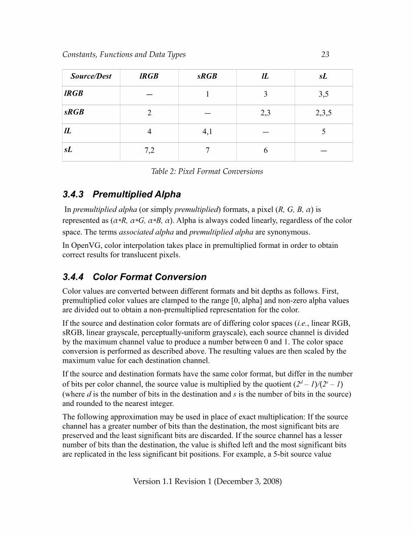
The remaining conversions take place in multiple steps, as shown in Table 2 below. The source format is indicated by the left column, and the destination format is indicated by the top row. The numbers indicate the equations from this section that are to be applied, in left-to-right order.
Version 1.1 Revision 1 (December 3, 2008)
Constants, Functions and Data Types 23
Source/Dest lRGB sRGB lL sL
lRGB — 1 3 3,5
sRGB 2 — 2,3 2,3,5
lL 4 4,1 — 5
sL 7,2 7 6 —
Table 2: Pixel Format Conversions
3.4.3 Premultiplied Alpha In premultiplied alpha (or simply premultiplied) formats, a pixel (R, G, B, α) is represented as (α*R, α*G, α*B, α). Alpha is always coded linearly, regardless of the color space. The terms associated alpha and premultiplied alpha are synonymous.
In OpenVG, color interpolation takes place in premultiplied format in order to obtain correct results for translucent pixels.
3.4.4 Color Format ConversionColor values are converted between different formats and bit depths as follows. First, premultiplied color values are clamped to the range [0, alpha] and non-zero alpha values are divided out to obtain a non-premultiplied representation for the color.
If the source and destination color formats are of differing color spaces (i.e., linear RGB, sRGB, linear grayscale, perceptually-uniform grayscale), each source channel is divided by the maximum channel value to produce a number between 0 and 1. The color space conversion is performed as described above. The resulting values are then scaled by the maximum value for each destination channel.
If the source and destination formats have the same color format, but differ in the number of bits per color channel, the source value is multiplied by the quotient (2d – 1)/(2s – 1) (where d is the number of bits in the destination and s is the number of bits in the source) and rounded to the nearest integer.
The following approximation may be used in place of exact multiplication: If the source channel has a greater number of bits than the destination, the most significant bits are preserved and the least significant bits are discarded. If the source channel has a lesser number of bits than the destination, the value is shifted left and the most significant bits are replicated in the less significant bit positions. For example, a 5-bit source value
Version 1.1 Revision 1 (December 3, 2008)
Constants, Functions and Data Types 24
b4b3b2b1b0 will be converted to an 8-bit destination value b4b3b2b1b0b4b3b2. This rule approximates the correct result since if d = k*s for some integer k > 1 the quotient (2d – 1)/(2s – 1) will be an integer of the form 2(k-1)*s + 2(k-2)*s + ... + 2s + 1, and multiplication of an s-bit value by this value will be exactly equivalent to bit replication. When the destination bit depth is not an integer multiple of the source bit depth, this rule still provides greater accuracy than other possible approximations such as padding the source with zeros or with copies of the rightmost bit.
Note that converting from a lesser to a greater number of bits and back again using either exact scaling or the approximation will result in an unchanged value.
If the destination format has stored alpha, the previously saved alpha value is stored into the destination. If the destination format has premultiplied alpha, each color channel value is multiplied by the corresponding alpha value and the resulting values are clamped to the range [0, alpha].
3.5 Enumerated Data TypesA number of data types are defined using the C enum keyword. In all cases, this specification assigns each enumerated constant a particular integer value. Extensions to the specification wishing to add new enumerated values must register with the Khronos Group to receive a unique value (see Section 15).
Applications making use of extensions should cast the extension-defined integer value to the proper enumerated type.
The enumerated types (apart from VGboolean) defined by OpenVG are:
• VGBlendMode• VGCapStyle• VGColorRampSpreadMode• VGErrorCode• VGFillRule• VGFontParamType• VGHardwareQueryResult• VGHardwareQueryType• VGImageChannel• VGImageFormat• VGImageMode• VGImageParamType• VGImageQuality• VGJoinStyle• VGMaskOperation
• VGMatrixMode• VGPaintMode• VGPaintParamType• VGPaintType• VGParamType• VGPathAbsRel• VGPathCapabilities• VGPathCommand• VGPathDatatype• VGPathParamType• VGPathSegment• VGPixelLayout• VGRenderingQuality• VGStringID• VGTilingMode
Version 1.1 Revision 1 (December 3, 2008)
Constants, Functions and Data Types 25
The VGU utility library defines the enumerated types:
• VGUArcType • VGUErrorCode
3.6 Handle-based Data TypesImages, paint objects, and paths are accessed using opaque handles. The use of handles allows these potentially large and complex objects to be stored under API control. For example, they may be stored in special memory and/or formatted in a way that is suitable for use by a hardware implementation. Handles are created relative to the current context, and may only be used as OpenVG function parameters when that context or one of its shared contexts is current.
Handles employ reference count semantics; if a handle is in use by the implementation, a request to destroy the handle prevents the handle from being used further by the application, but allows it to continue to be used internally by the implementation until it is no longer referenced.
VGHandleHandles make use of the VGHandle data type. For reasons of binary compatibility between different OpenVG implementations on a given platform, a VGHandle is defined as a VGuint.typedef VGuint VGHandle;
Live handles to distinct objects must compare as unequal using the C == (double equals) operator.
The VGHandle subtypes defined in the API are:
• VGFont – a reference to font data (see Section 11)• VGImage – a reference to image data (see Section 10)• VGMaskLayer – a reference to mask data (see Section 7.2)• VGPaint – a reference to a paint specification (see Section 9)• VGPath – a reference to path data (see Section 8)
Version 1.1 Revision 1 (December 3, 2008)
Constants, Functions and Data Types 26
VG_INVALID_HANDLEThe symbol VG_INVALID_HANDLE represents an invalid VGHandle that is used as an error return value from functions that return a VGHandle. VG_INVALID_HANDLE is defined as (VGHandle)0.#define VG_INVALID_HANDLE ((VGHandle)0)
Version 1.1 Revision 1 (December 3, 2008)
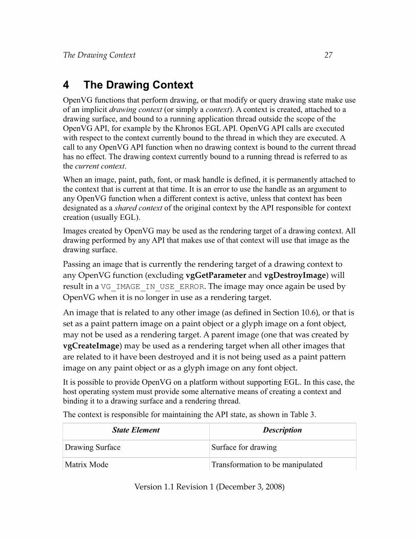
The Drawing Context 27
4 The Drawing ContextOpenVG functions that perform drawing, or that modify or query drawing state make use of an implicit drawing context (or simply a context). A context is created, attached to a drawing surface, and bound to a running application thread outside the scope of the OpenVG API, for example by the Khronos EGL API. OpenVG API calls are executed with respect to the context currently bound to the thread in which they are executed. A call to any OpenVG API function when no drawing context is bound to the current thread has no effect. The drawing context currently bound to a running thread is referred to as the current context.When an image, paint, path, font, or mask handle is defined, it is permanently attached to the context that is current at that time. It is an error to use the handle as an argument to any OpenVG function when a different context is active, unless that context has been designated as a shared context of the original context by the API responsible for context creation (usually EGL).
Images created by OpenVG may be used as the rendering target of a drawing context. All drawing performed by any API that makes use of that context will use that image as the drawing surface.
Passing an image that is currently the rendering target of a drawing context to any OpenVG function (excluding vgGetParameter and vgDestroyImage) will result in a VG_IMAGE_IN_USE_ERROR. The image may once again be used by OpenVG when it is no longer in use as a rendering target.
An image that is related to any other image (as defined in Section 10.6), or that is set as a paint pattern image on a paint object or a glyph image on a font object, may not be used as a rendering target. A parent image (one that was created by vgCreateImage) may be used as a rendering target when all other images that are related to it have been destroyed and it is not being used as a paint pattern image on any paint object or as a glyph image on any font object.
It is possible to provide OpenVG on a platform without supporting EGL. In this case, the host operating system must provide some alternative means of creating a context and binding it to a drawing surface and a rendering thread.
The context is responsible for maintaining the API state, as shown in Table 3.
State Element Description
Drawing Surface Surface for drawing
Matrix Mode Transformation to be manipulated
Version 1.1 Revision 1 (December 3, 2008)
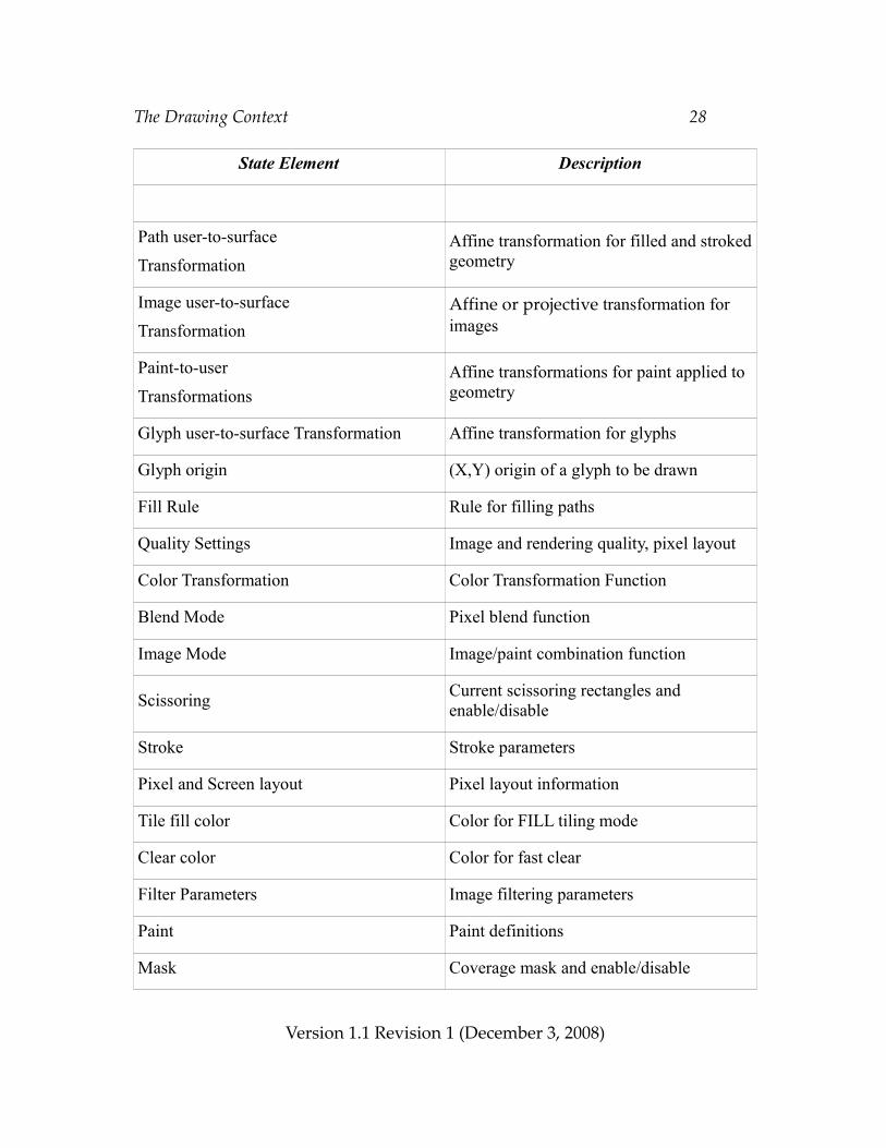
The Drawing Context 28
State Element Description
Path user-to-surface
TransformationAffine transformation for filled and stroked geometry
Image user-to-surface
TransformationAffine or projective transformation for images
Paint-to-user
TransformationsAffine transformations for paint applied to geometry
Glyph user-to-surface Transformation Affine transformation for glyphs
Glyph origin (X,Y) origin of a glyph to be drawn
Fill Rule Rule for filling paths
Quality Settings Image and rendering quality, pixel layout
Color Transformation Color Transformation Function
Blend Mode Pixel blend function
Image Mode Image/paint combination function
Scissoring Current scissoring rectangles and enable/disable
Stroke Stroke parameters
Pixel and Screen layout Pixel layout information
Tile fill color Color for FILL tiling mode
Clear color Color for fast clear
Filter Parameters Image filtering parameters
Paint Paint definitions
Mask Coverage mask and enable/disable
Version 1.1 Revision 1 (December 3, 2008)
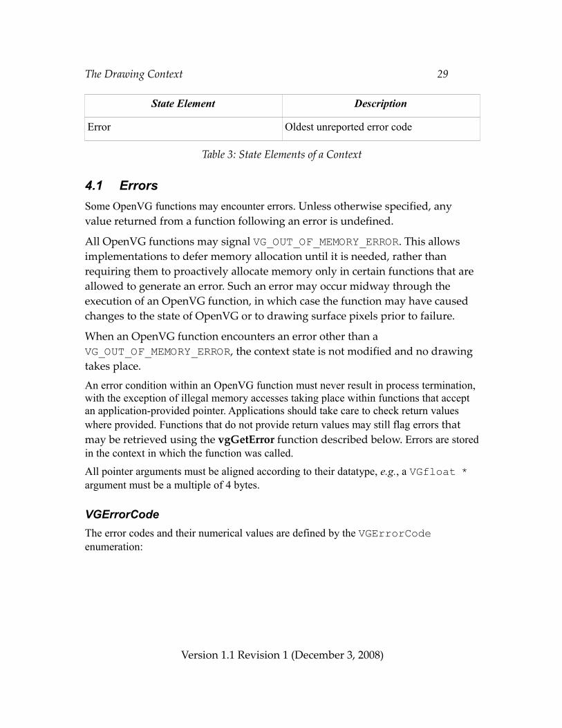
The Drawing Context 29
State Element Description
Error Oldest unreported error code
Table 3: State Elements of a Context
4.1 ErrorsSome OpenVG functions may encounter errors. Unless otherwise specified, any value returned from a function following an error is undefined.
All OpenVG functions may signal VG_OUT_OF_MEMORY_ERROR. This allows implementations to defer memory allocation until it is needed, rather than requiring them to proactively allocate memory only in certain functions that are allowed to generate an error. Such an error may occur midway through the execution of an OpenVG function, in which case the function may have caused changes to the state of OpenVG or to drawing surface pixels prior to failure.
When an OpenVG function encounters an error other than a VG_OUT_OF_MEMORY_ERROR, the context state is not modified and no drawing takes place.
An error condition within an OpenVG function must never result in process termination, with the exception of illegal memory accesses taking place within functions that accept an application-provided pointer. Applications should take care to check return values where provided. Functions that do not provide return values may still flag errors that may be retrieved using the vgGetError function described below. Errors are stored in the context in which the function was called.
All pointer arguments must be aligned according to their datatype, e.g., a VGfloat * argument must be a multiple of 4 bytes.
VGErrorCodeThe error codes and their numerical values are defined by the VGErrorCode enumeration:
Version 1.1 Revision 1 (December 3, 2008)
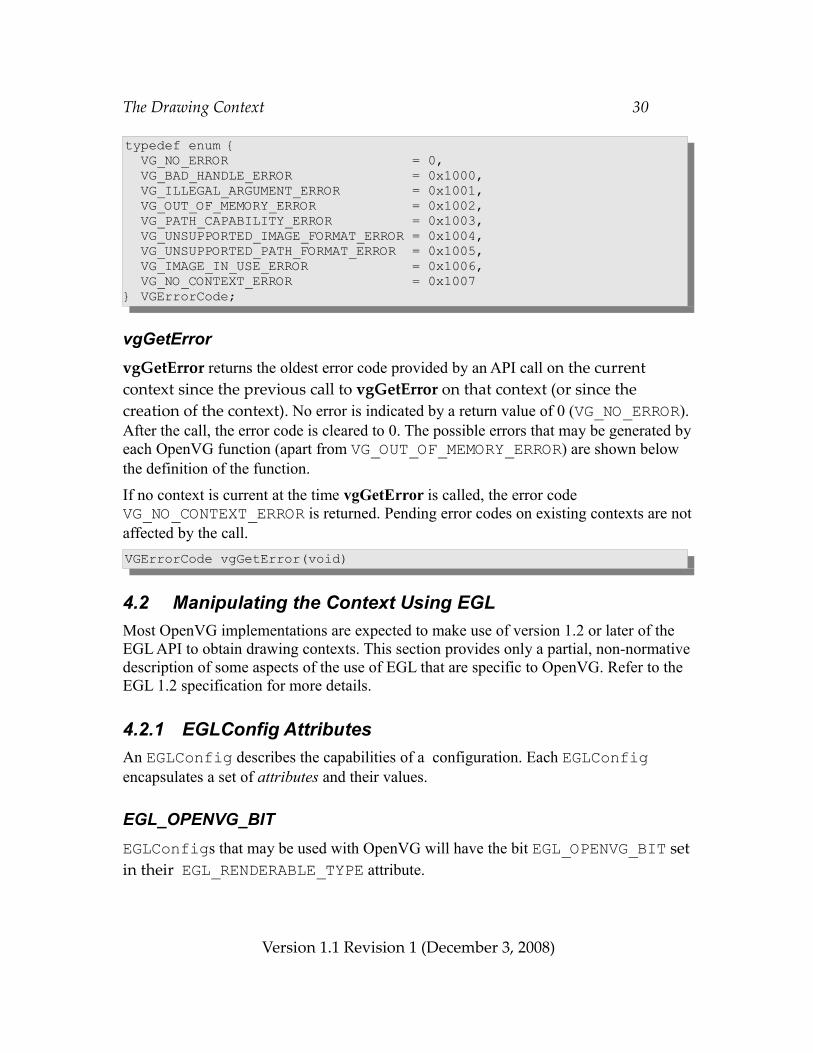
The Drawing Context 30
typedef enum { VG_NO_ERROR = 0, VG_BAD_HANDLE_ERROR = 0x1000, VG_ILLEGAL_ARGUMENT_ERROR = 0x1001, VG_OUT_OF_MEMORY_ERROR = 0x1002, VG_PATH_CAPABILITY_ERROR = 0x1003, VG_UNSUPPORTED_IMAGE_FORMAT_ERROR = 0x1004, VG_UNSUPPORTED_PATH_FORMAT_ERROR = 0x1005, VG_IMAGE_IN_USE_ERROR = 0x1006, VG_NO_CONTEXT_ERROR = 0x1007} VGErrorCode;
vgGetErrorvgGetError returns the oldest error code provided by an API call on the current context since the previous call to vgGetError on that context (or since the creation of the context). No error is indicated by a return value of 0 (VG_NO_ERROR). After the call, the error code is cleared to 0. The possible errors that may be generated by each OpenVG function (apart from VG_OUT_OF_MEMORY_ERROR) are shown below the definition of the function.
If no context is current at the time vgGetError is called, the error code VG_NO_CONTEXT_ERROR is returned. Pending error codes on existing contexts are not affected by the call.VGErrorCode vgGetError(void)
4.2 Manipulating the Context Using EGLMost OpenVG implementations are expected to make use of version 1.2 or later of the EGL API to obtain drawing contexts. This section provides only a partial, non-normative description of some aspects of the use of EGL that are specific to OpenVG. Refer to the EGL 1.2 specification for more details.
4.2.1 EGLConfig AttributesAn EGLConfig describes the capabilities of a configuration. Each EGLConfig encapsulates a set of attributes and their values.
EGL_OPENVG_BITEGLConfigs that may be used with OpenVG will have the bit EGL_OPENVG_BIT set in their EGL_RENDERABLE_TYPE attribute.
Version 1.1 Revision 1 (December 3, 2008)
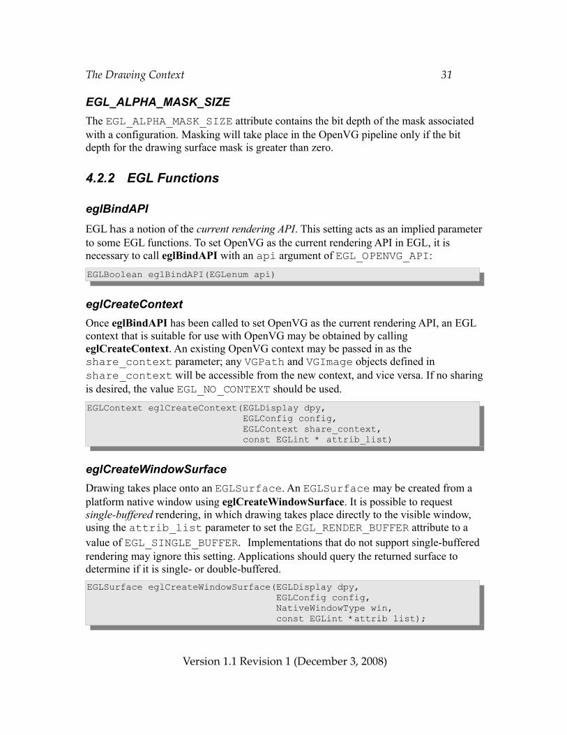
The Drawing Context 31
EGL_ALPHA_MASK_SIZEThe EGL_ALPHA_MASK_SIZE attribute contains the bit depth of the mask associated with a configuration. Masking will take place in the OpenVG pipeline only if the bit depth for the drawing surface mask is greater than zero.
4.2.2 EGL Functions
eglBindAPIEGL has a notion of the current rendering API. This setting acts as an implied parameter to some EGL functions. To set OpenVG as the current rendering API in EGL, it is necessary to call eglBindAPI with an api argument of EGL_OPENVG_API:EGLBoolean eglBindAPI(EGLenum api)
eglCreateContextOnce eglBindAPI has been called to set OpenVG as the current rendering API, an EGL context that is suitable for use with OpenVG may be obtained by calling eglCreateContext. An existing OpenVG context may be passed in as the share_context parameter; any VGPath and VGImage objects defined in share_context will be accessible from the new context, and vice versa. If no sharing is desired, the value EGL_NO_CONTEXT should be used. EGLContext eglCreateContext(EGLDisplay dpy, EGLConfig config, EGLContext share_context, const EGLint * attrib_list)
eglCreateWindowSurfaceDrawing takes place onto an EGLSurface. An EGLSurface may be created from a platform native window using eglCreateWindowSurface. It is possible to request single-buffered rendering, in which drawing takes place directly to the visible window, using the attrib_list parameter to set the EGL_RENDER_BUFFER attribute to a value of EGL_SINGLE_BUFFER. Implementations that do not support single-buffered rendering may ignore this setting. Applications should query the returned surface to determine if it is single- or double-buffered.EGLSurface eglCreateWindowSurface(EGLDisplay dpy, EGLConfig config, NativeWindowType win, const EGLint *attrib list);
Version 1.1 Revision 1 (December 3, 2008)
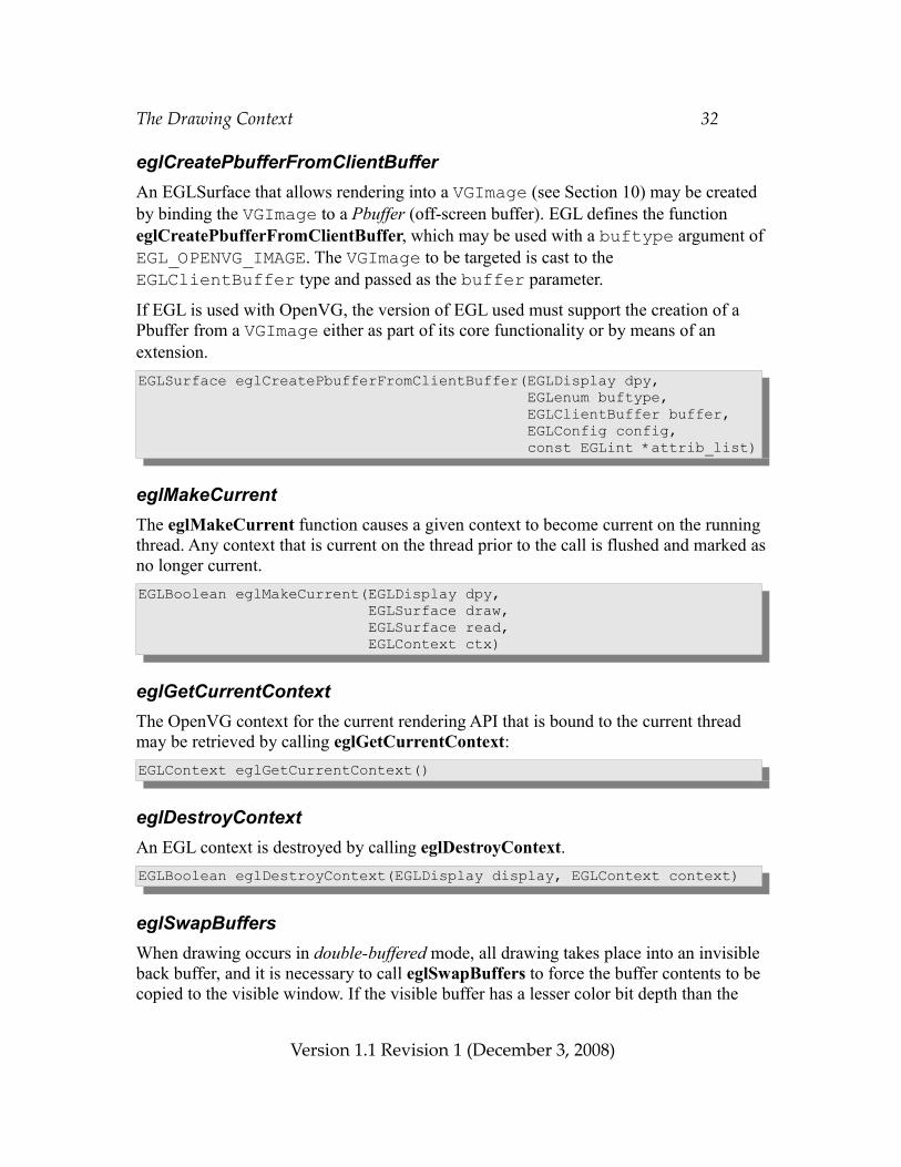
The Drawing Context 32
eglCreatePbufferFromClientBufferAn EGLSurface that allows rendering into a VGImage (see Section 10) may be created by binding the VGImage to a Pbuffer (off-screen buffer). EGL defines the function eglCreatePbufferFromClientBuffer, which may be used with a buftype argument of EGL_OPENVG_IMAGE. The VGImage to be targeted is cast to the EGLClientBuffer type and passed as the buffer parameter.
If EGL is used with OpenVG, the version of EGL used must support the creation of a Pbuffer from a VGImage either as part of its core functionality or by means of an extension.EGLSurface eglCreatePbufferFromClientBuffer(EGLDisplay dpy, EGLenum buftype, EGLClientBuffer buffer, EGLConfig config, const EGLint *attrib_list)
eglMakeCurrentThe eglMakeCurrent function causes a given context to become current on the running thread. Any context that is current on the thread prior to the call is flushed and marked as no longer current.EGLBoolean eglMakeCurrent(EGLDisplay dpy, EGLSurface draw, EGLSurface read, EGLContext ctx)
eglGetCurrentContextThe OpenVG context for the current rendering API that is bound to the current thread may be retrieved by calling eglGetCurrentContext:EGLContext eglGetCurrentContext()
eglDestroyContextAn EGL context is destroyed by calling eglDestroyContext.EGLBoolean eglDestroyContext(EGLDisplay display, EGLContext context)
eglSwapBuffersWhen drawing occurs in double-buffered mode, all drawing takes place into an invisible back buffer, and it is necessary to call eglSwapBuffers to force the buffer contents to be copied to the visible window. If the visible buffer has a lesser color bit depth than the
Version 1.1 Revision 1 (December 3, 2008)
The Drawing Context 33
back buffer, dithering may be performed as part of the buffer copy operation.EGLBoolean eglSwapBuffers(EGLDisplay dpy, EGLSurface surface);
4.3 Forcing Drawing to CompleteOpenVG provides functions to force the completion of rendering, in order to allow applications to synchronize between multiple rendering APIs.
vgFlushThe vgFlush function ensures that all outstanding requests on the current context will complete in finite time. vgFlush may return prior to the actual completion of all requests.void vgFlush(void)
vgFinishThe vgFinish function forces all outstanding requests on the current context to complete, returning only when the last request has completed.void vgFinish(void)
Version 1.1 Revision 1 (December 3, 2008)
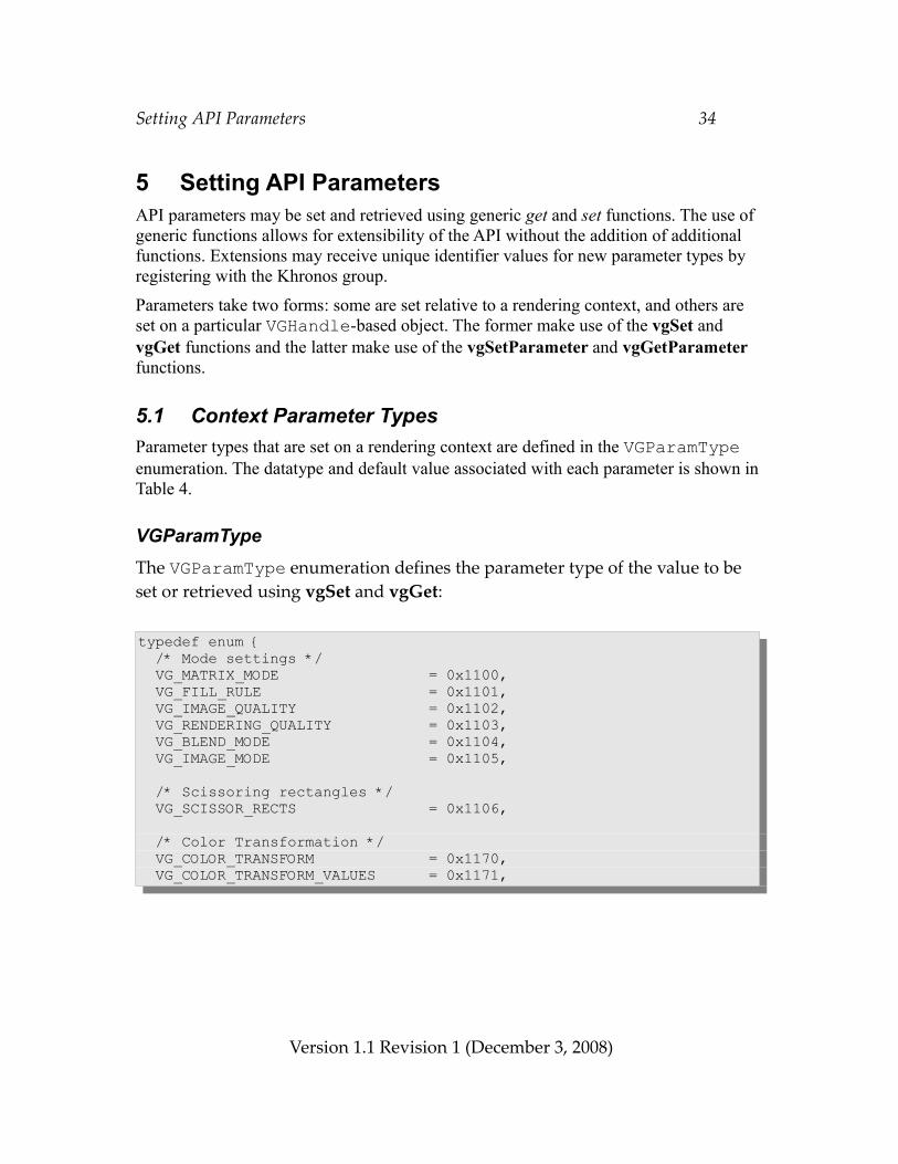
Setting API Parameters 34
5 Setting API ParametersAPI parameters may be set and retrieved using generic get and set functions. The use of generic functions allows for extensibility of the API without the addition of additional functions. Extensions may receive unique identifier values for new parameter types by registering with the Khronos group.
Parameters take two forms: some are set relative to a rendering context, and others are set on a particular VGHandle-based object. The former make use of the vgSet and vgGet functions and the latter make use of the vgSetParameter and vgGetParameter functions.
5.1 Context Parameter TypesParameter types that are set on a rendering context are defined in the VGParamType enumeration. The datatype and default value associated with each parameter is shown in Table 4.
VGParamTypeThe VGParamType enumeration defines the parameter type of the value to be set or retrieved using vgSet and vgGet:
typedef enum { /* Mode settings */ VG_MATRIX_MODE = 0x1100, VG_FILL_RULE = 0x1101, VG_IMAGE_QUALITY = 0x1102, VG_RENDERING_QUALITY = 0x1103, VG_BLEND_MODE = 0x1104, VG_IMAGE_MODE = 0x1105,
/* Scissoring rectangles */ VG_SCISSOR_RECTS = 0x1106,
/* Color Transformation */ VG_COLOR_TRANSFORM = 0x1170, VG_COLOR_TRANSFORM_VALUES = 0x1171,
Version 1.1 Revision 1 (December 3, 2008)
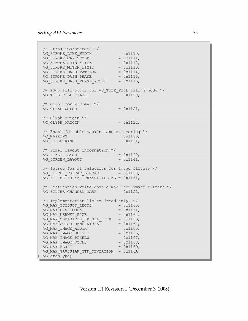
Setting API Parameters 35
/* Stroke parameters */ VG_STROKE_LINE_WIDTH = 0x1110, VG_STROKE_CAP_STYLE = 0x1111, VG_STROKE_JOIN_STYLE = 0x1112, VG_STROKE_MITER_LIMIT = 0x1113, VG_STROKE_DASH_PATTERN = 0x1114, VG_STROKE_DASH_PHASE = 0x1115, VG_STROKE_DASH_PHASE_RESET = 0x1116,
/* Edge fill color for VG_TILE_FILL tiling mode */ VG_TILE_FILL_COLOR = 0x1120,
/* Color for vgClear */ VG_CLEAR_COLOR = 0x1121,
/* Glyph origin */ VG_GLYPH_ORIGIN = 0x1122,
/* Enable/disable masking and scissoring */ VG_MASKING = 0x1130, VG_SCISSORING = 0x1131,
/* Pixel layout information */ VG_PIXEL_LAYOUT = 0x1140, VG_SCREEN_LAYOUT = 0x1141,
/* Source format selection for image filters */ VG_FILTER_FORMAT_LINEAR = 0x1150, VG_FILTER_FORMAT_PREMULTIPLIED = 0x1151,
/* Destination write enable mask for image filters */ VG_FILTER_CHANNEL_MASK = 0x1152,
/* Implementation limits (read-only) */ VG_MAX_SCISSOR_RECTS = 0x1160, VG_MAX_DASH_COUNT = 0x1161, VG_MAX_KERNEL_SIZE = 0x1162, VG_MAX_SEPARABLE_KERNEL_SIZE = 0x1163, VG_MAX_COLOR_RAMP_STOPS = 0x1164, VG_MAX_IMAGE_WIDTH = 0x1165, VG_MAX_IMAGE_HEIGHT = 0x1166, VG_MAX_IMAGE_PIXELS = 0x1167, VG_MAX_IMAGE_BYTES = 0x1168, VG_MAX_FLOAT = 0x1169, VG_MAX_GAUSSIAN_STD_DEVIATION = 0x116A} VGParamType;
Version 1.1 Revision 1 (December 3, 2008)
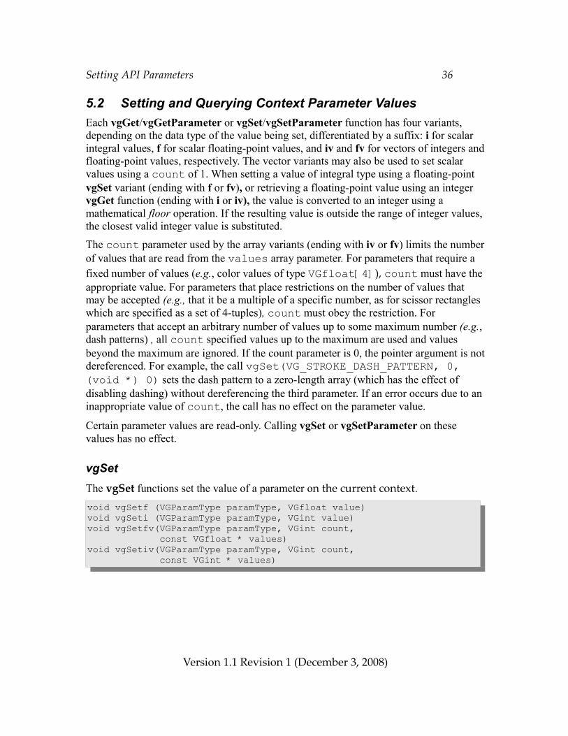
Setting API Parameters 36
5.2 Setting and Querying Context Parameter ValuesEach vgGet/vgGetParameter or vgSet/vgSetParameter function has four variants, depending on the data type of the value being set, differentiated by a suffix: i for scalar integral values, f for scalar floating-point values, and iv and fv for vectors of integers and floating-point values, respectively. The vector variants may also be used to set scalar values using a count of 1. When setting a value of integral type using a floating-point vgSet variant (ending with f or fv), or retrieving a floating-point value using an integer vgGet function (ending with i or iv), the value is converted to an integer using a mathematical floor operation. If the resulting value is outside the range of integer values, the closest valid integer value is substituted.
The count parameter used by the array variants (ending with iv or fv) limits the number of values that are read from the values array parameter. For parameters that require a fixed number of values (e.g., color values of type VGfloat[4]), count must have the appropriate value. For parameters that place restrictions on the number of values that may be accepted (e.g., that it be a multiple of a specific number, as for scissor rectangles which are specified as a set of 4-tuples), count must obey the restriction. For parameters that accept an arbitrary number of values up to some maximum number (e.g., dash patterns) , all count specified values up to the maximum are used and values beyond the maximum are ignored. If the count parameter is 0, the pointer argument is not dereferenced. For example, the call vgSet(VG_STROKE_DASH_PATTERN, 0, (void *) 0) sets the dash pattern to a zero-length array (which has the effect of disabling dashing) without dereferencing the third parameter. If an error occurs due to an inappropriate value of count, the call has no effect on the parameter value.
Certain parameter values are read-only. Calling vgSet or vgSetParameter on these values has no effect.
vgSetThe vgSet functions set the value of a parameter on the current context.void vgSetf (VGParamType paramType, VGfloat value)void vgSeti (VGParamType paramType, VGint value)void vgSetfv(VGParamType paramType, VGint count, const VGfloat * values)void vgSetiv(VGParamType paramType, VGint count, const VGint * values)
Version 1.1 Revision 1 (December 3, 2008)
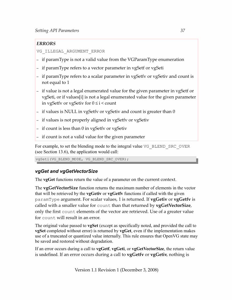
Setting API Parameters 37
ERRORSVG_ILLEGAL_ARGUMENT_ERROR– if paramType is not a valid value from the VGParamType enumeration
– if paramType refers to a vector parameter in vgSetf or vgSeti
– if paramType refers to a scalar parameter in vgSetfv or vgSetiv and count is not equal to 1
– if value is not a legal enumerated value for the given parameter in vgSetf or vgSeti, or if values[i] is not a legal enumerated value for the given parameter in vgSetfv or vgSetiv for 0 ≤ i < count
– if values is NULL in vgSetfv or vgSetiv and count is greater than 0
– if values is not properly aligned in vgSetfv or vgSetiv
– if count is less than 0 in vgSetfv or vgSetiv
– if count is not a valid value for the given parameter For example, to set the blending mode to the integral value VG_BLEND_SRC_OVER (see Section 13.6), the application would call:vgSeti(VG_BLEND_MODE, VG_BLEND_SRC_OVER);
vgGet and vgGetVectorSizeThe vgGet functions return the value of a parameter on the current context.
The vgGetVectorSize function returns the maximum number of elements in the vector that will be retrieved by the vgGetiv or vgGetfv functions if called with the given paramType argument. For scalar values, 1 is returned. If vgGetiv or vgGetfv is called with a smaller value for count than that returned by vgGetVectorSize, only the first count elements of the vector are retrieved. Use of a greater value for count will result in an error.
The original value passed to vgSet (except as specifically noted, and provided the call to vgSet completed without error) is returned by vgGet, even if the implementation makes use of a truncated or quantized value internally. This rule ensures that OpenVG state may be saved and restored without degradation.
If an error occurs during a call to vgGetf, vgGeti, or vgGetVectorSize, the return value is undefined. If an error occurs during a call to vgGetfv or vgGetiv, nothing is
Version 1.1 Revision 1 (December 3, 2008)
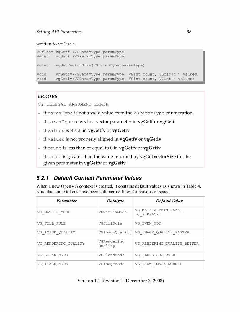
Setting API Parameters 38
written to values.VGfloat vgGetf (VGParamType paramType)VGint vgGeti (VGParamType paramType)
VGint vgGetVectorSize(VGParamType paramType)
void vgGetfv(VGParamType paramType, VGint count, VGfloat * values)void vgGetiv(VGParamType paramType, VGint count, VGint * values)
ERRORSVG_ILLEGAL_ARGUMENT_ERROR– if paramType is not a valid value from the VGParamType enumeration
– if paramType refers to a vector parameter in vgGetf or vgGeti
– if values is NULL in vgGetfv or vgGetiv
– if values is not properly aligned in vgGetfv or vgGetiv
– if count is less than or equal to 0 in vgGetfv or vgGetiv
– if count is greater than the value returned by vgGetVectorSize for the given parameter in vgGetfv or vgGetiv
5.2.1 Default Context Parameter ValuesWhen a new OpenVG context is created, it contains default values as shown in Table 4. Note that some tokens have been split across lines for reasons of space.
Parameter Datatype Default Value
VG_MATRIX_MODE VGMatrixMode VG_MATRIX_PATH_USER_TO_SURFACE
VG_FILL_RULE VGFillRule VG_EVEN_ODD
VG_IMAGE_QUALITY VGImageQuality VG_IMAGE_QUALITY_FASTER
VG_RENDERING_QUALITY VGRenderingQuality VG_RENDERING_QUALITY_BETTER
VG_BLEND_MODE VGBlendMode VG_BLEND_SRC_OVER
VG_IMAGE_MODE VGImageMode VG_DRAW_IMAGE_NORMAL
Version 1.1 Revision 1 (December 3, 2008)
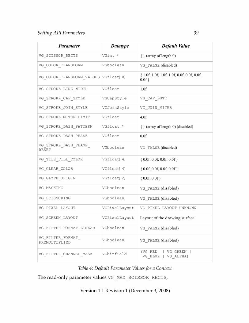
Setting API Parameters 39
Parameter Datatype Default Value
VG_SCISSOR_RECTS VGint * { } (array of length 0)
VG_COLOR_TRANSFORM VGboolean VG_FALSE (disabled)
VG_COLOR_TRANSFORM_VALUES VGfloat[8] { 1.0f, 1.0f, 1.0f, 1.0f, 0.0f, 0.0f, 0.0f, 0.0f }
VG_STROKE_LINE_WIDTH VGfloat 1.0f
VG_STROKE_CAP_STYLE VGCapStyle VG_CAP_BUTT
VG_STROKE_JOIN_STYLE VGJoinStyle VG_JOIN_MITER
VG_STROKE_MITER_LIMIT VGfloat 4.0f
VG_STROKE_DASH_PATTERN VGfloat * { } (array of length 0) (disabled)
VG_STROKE_DASH_PHASE VGfloat 0.0f
VG_STROKE_DASH_PHASE_RESET VGboolean VG_FALSE (disabled)
VG_TILE_FILL_COLOR VGfloat[4] { 0.0f, 0.0f, 0.0f, 0.0f }
VG_CLEAR_COLOR VGfloat[4] { 0.0f, 0.0f, 0.0f, 0.0f }
VG_GLYPH_ORIGIN VGfloat[2] { 0.0f, 0.0f }
VG_MASKING VGboolean VG_FALSE (disabled)
VG_SCISSORING VGboolean VG_FALSE (disabled)
VG_PIXEL_LAYOUT VGPixelLayout VG_PIXEL_LAYOUT_UNKNOWN
VG_SCREEN_LAYOUT VGPixelLayout Layout of the drawing surface
VG_FILTER_FORMAT_LINEAR VGboolean VG_FALSE (disabled)
VG_FILTER_FORMAT_PREMULTIPLIED VGboolean VG_FALSE (disabled)
VG_FILTER_CHANNEL_MASK VGbitfield (VG_RED | VG_GREEN | VG_BLUE | VG_ALPHA)
Table 4: Default Parameter Values for a Context
The read-only parameter values VG_MAX_SCISSOR_RECTS,
Version 1.1 Revision 1 (December 3, 2008)
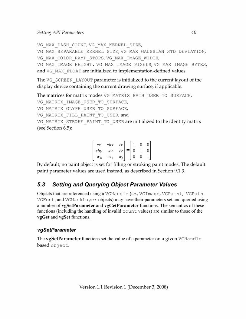
Setting API Parameters 40
VG_MAX_DASH_COUNT, VG_MAX_KERNEL_SIZE, VG_MAX_SEPARABLE_KERNEL_SIZE, VG_MAX_GAUSSIAN_STD_DEVIATION, VG_MAX_COLOR_RAMP_STOPS, VG_MAX_IMAGE_WIDTH, VG_MAX_IMAGE_HEIGHT, VG_MAX_IMAGE_PIXELS, VG_MAX_IMAGE_BYTES, and VG_MAX_FLOAT are initialized to implementation-defined values.
The VG_SCREEN_LAYOUT parameter is initialized to the current layout of the display device containing the current drawing surface, if applicable.
The matrices for matrix modes VG_MATRIX_PATH_USER_TO_SURFACE, VG_MATRIX_IMAGE_USER_TO_SURFACE, VG_MATRIX_GLYPH_USER_TO_SURFACE, VG_MATRIX_FILL_PAINT_TO_USER, and VG_MATRIX_STROKE_PAINT_TO_USER are initialized to the identity matrix (see Section 6.5):
By default, no paint object is set for filling or stroking paint modes. The default paint parameter values are used instead, as described in Section 9.1.3.
5.3 Setting and Querying Object Parameter ValuesObjects that are referenced using a VGHandle (i.e., VGImage, VGPaint, VGPath, VGFont, and VGMaskLayer objects) may have their parameters set and queried using a number of vgSetParameter and vgGetParameter functions. The semantics of these functions (including the handling of invalid count values) are similar to those of the vgGet and vgSet functions.
vgSetParameterThe vgSetParameter functions set the value of a parameter on a given VGHandle-based object.
Version 1.1 Revision 1 (December 3, 2008)
[ sx shx txshy sy tyw0 w1 w2
]=[ 1 0 00 1 00 0 1]
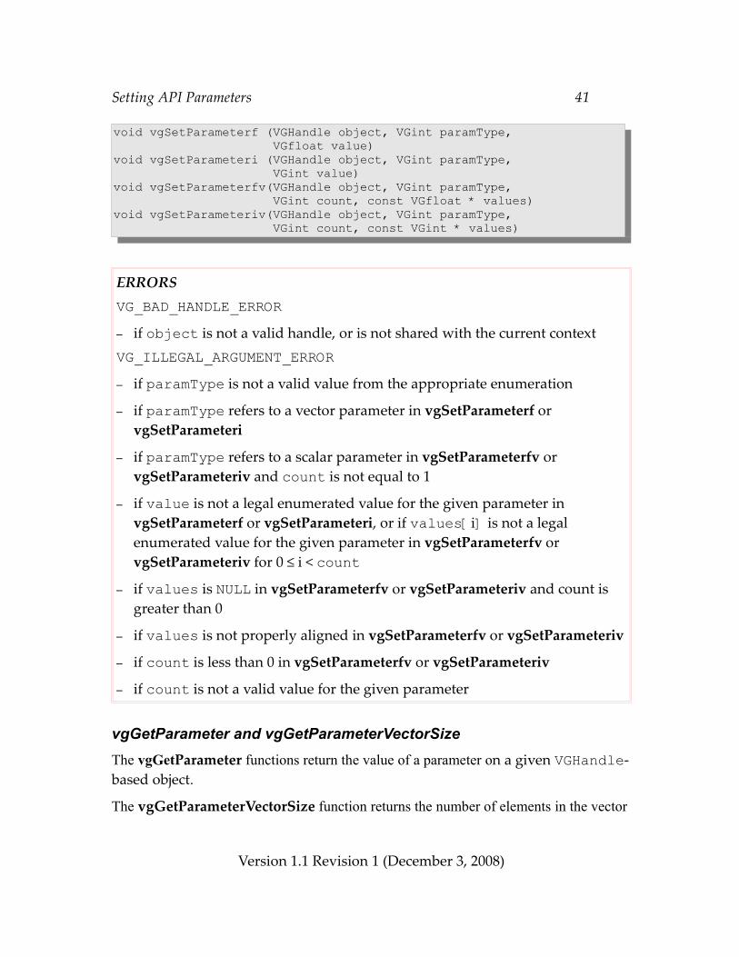
Setting API Parameters 41
void vgSetParameterf (VGHandle object, VGint paramType, VGfloat value)void vgSetParameteri (VGHandle object, VGint paramType, VGint value)void vgSetParameterfv(VGHandle object, VGint paramType, VGint count, const VGfloat * values)void vgSetParameteriv(VGHandle object, VGint paramType, VGint count, const VGint * values)
ERRORSVG_BAD_HANDLE_ERROR– if object is not a valid handle, or is not shared with the current contextVG_ILLEGAL_ARGUMENT_ERROR– if paramType is not a valid value from the appropriate enumeration
– if paramType refers to a vector parameter in vgSetParameterf or vgSetParameteri
– if paramType refers to a scalar parameter in vgSetParameterfv or vgSetParameteriv and count is not equal to 1
– if value is not a legal enumerated value for the given parameter in vgSetParameterf or vgSetParameteri, or if values[i] is not a legal enumerated value for the given parameter in vgSetParameterfv or vgSetParameteriv for 0 ≤ i < count
– if values is NULL in vgSetParameterfv or vgSetParameteriv and count is greater than 0
– if values is not properly aligned in vgSetParameterfv or vgSetParameteriv
– if count is less than 0 in vgSetParameterfv or vgSetParameteriv
– if count is not a valid value for the given parameter
vgGetParameter and vgGetParameterVectorSizeThe vgGetParameter functions return the value of a parameter on a given VGHandle-based object.
The vgGetParameterVectorSize function returns the number of elements in the vector
Version 1.1 Revision 1 (December 3, 2008)
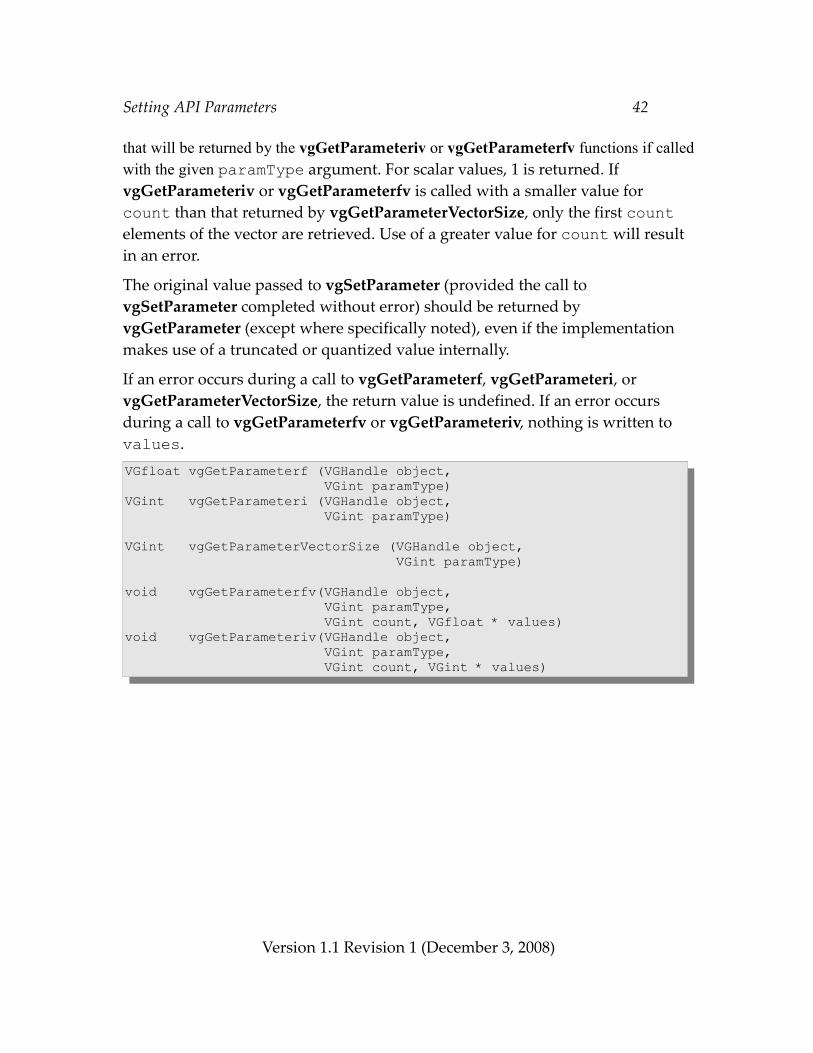
Setting API Parameters 42
that will be returned by the vgGetParameteriv or vgGetParameterfv functions if called with the given paramType argument. For scalar values, 1 is returned. If vgGetParameteriv or vgGetParameterfv is called with a smaller value for count than that returned by vgGetParameterVectorSize, only the first count elements of the vector are retrieved. Use of a greater value for count will result in an error.
The original value passed to vgSetParameter (provided the call to vgSetParameter completed without error) should be returned by vgGetParameter (except where specifically noted), even if the implementation makes use of a truncated or quantized value internally.
If an error occurs during a call to vgGetParameterf, vgGetParameteri, or vgGetParameterVectorSize, the return value is undefined. If an error occurs during a call to vgGetParameterfv or vgGetParameteriv, nothing is written to values.VGfloat vgGetParameterf (VGHandle object, VGint paramType)VGint vgGetParameteri (VGHandle object, VGint paramType)
VGint vgGetParameterVectorSize (VGHandle object, VGint paramType)
void vgGetParameterfv(VGHandle object, VGint paramType, VGint count, VGfloat * values)void vgGetParameteriv(VGHandle object, VGint paramType, VGint count, VGint * values)
Version 1.1 Revision 1 (December 3, 2008)
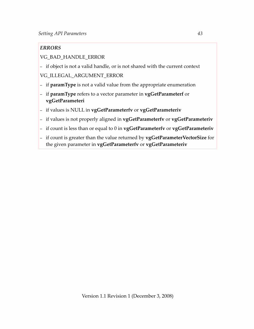
Setting API Parameters 43
ERRORS
VG_BAD_HANDLE_ERROR
– if object is not a valid handle, or is not shared with the current context
VG_ILLEGAL_ARGUMENT_ERROR
– if paramType is not a valid value from the appropriate enumeration
– if paramType refers to a vector parameter in vgGetParameterf or vgGetParameteri
– if values is NULL in vgGetParameterfv or vgGetParameteriv
– if values is not properly aligned in vgGetParameterfv or vgGetParameteriv
– if count is less than or equal to 0 in vgGetParameterfv or vgGetParameteriv
– if count is greater than the value returned by vgGetParameterVectorSize for the given parameter in vgGetParameterfv or vgGetParameteriv
Version 1.1 Revision 1 (December 3, 2008)
Rendering Quality and Antialiasing 44
6 Rendering Quality and AntialiasingRendering quality settings are available to control implementation-specific trade-offs between quality and performance. For example, an application might wish to use the highest quality setting for still images, and the fastest setting during UI operations or animation. The implementation must satisfy conformance requirements regardless of the quality setting.
A non-antialiased mode is provided for single-sampled drawing surfaces in which pixel coverage is always assigned to be 0 or 1, based on the inclusion of the pixel center in the geometry being rendered. When antialiasing is disabled, a coverage value of 1 will be assigned to each pixel whose center lies within the estimated path geometry, and a coverage value of 0 will be assigned otherwise. A consistent tie-breaking rule must be used for paths that pass through pixel centers.
For purposes of estimating whether a pixel center is included within a path, implementations may make use of approximations to the exact path geometry, providing that the following constraints are met. Conceptually, draw a disc D around each pixel center with a radius of just under ½ a pixel (in topological terms, an open disc of radius ½) and consider its intersection with the exact path geometry:
1. If D is entirely inside the path, the coverage at the pixel center must be estimated as 1;
2. If D is entirely outside the path, the coverage at the pixel center must be estimated as 0;
3. If D lies partially inside and partially outside the path, the coverage may be estimated as either 0 or 1 subject to the additional constraints that:a. The estimation is deterministic and invariant with respect to state variables apart from the current user-to-surface transformation, path coordinate geometry, and clipping due to different drawing surface dimensions; andb. For two disjoint paths that share a common segment, if D is partially covered by each path and completely covered by the union of the paths, the coverage must be estimated as 1 for exactly one of the paths. A segment is considered common to two paths if and only if both paths have the same path format, path datatype, scale, and bias, and the segments have bit-for-bit identical segment types and coordinate values, possibly in flipped order. If the segment is specified using relative coordinates, any preceding segments that may influence the segment must also have identical segment types and coordinate values.
Version 1.1 Revision 1 (December 3, 2008)
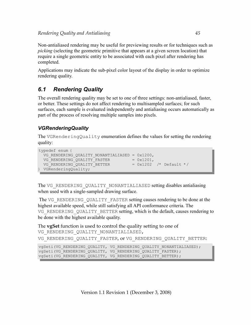
Rendering Quality and Antialiasing 45
Non-antialiased rendering may be useful for previewing results or for techniques such as picking (selecting the geometric primitive that appears at a given screen location) that require a single geometric entity to be associated with each pixel after rendering has completed.
Applications may indicate the sub-pixel color layout of the display in order to optimize rendering quality.
6.1 Rendering QualityThe overall rendering quality may be set to one of three settings: non-antialiased, faster, or better. These settings do not affect rendering to multisampled surfaces; for such surfaces, each sample is evaluated independently and antialiasing occurs automatically as part of the process of resolving multiple samples into pixels.
VGRenderingQualityThe VGRenderingQuality enumeration defines the values for setting the rendering quality:typedef enum { VG_RENDERING_QUALITY_NONANTIALIASED = 0x1200, VG_RENDERING_QUALITY_FASTER = 0x1201, VG_RENDERING_QUALITY_BETTER = 0x1202 /* Default */} VGRenderingQuality;
The VG_RENDERING_QUALITY_NONANTIALIASED setting disables antialiasing when used with a single-sampled drawing surface.
The VG_RENDERING_QUALITY_FASTER setting causes rendering to be done at the highest available speed, while still satisfying all API conformance criteria. The VG_RENDERING_QUALITY_BETTER setting, which is the default, causes rendering to be done with the highest available quality.
The vgSet function is used to control the quality setting to one of VG_RENDERING_QUALITY_NONANTIALIASED, VG_RENDERING_QUALITY_FASTER, or VG_RENDERING_QUALITY_BETTER:vgSeti(VG_RENDERING_QUALITY, VG_RENDERING_QUALITY_NONANTIALIASED);vgSeti(VG_RENDERING_QUALITY, VG_RENDERING_QUALITY_FASTER);vgSeti(VG_RENDERING_QUALITY, VG_RENDERING_QUALITY_BETTER);
Version 1.1 Revision 1 (December 3, 2008)
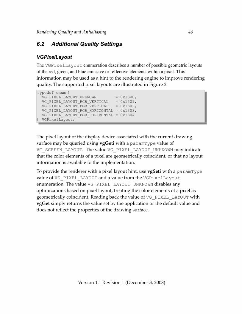
Rendering Quality and Antialiasing 46
6.2 Additional Quality Settings
VGPixelLayoutThe VGPixelLayout enumeration describes a number of possible geometric layouts of the red, green, and blue emissive or reflective elements within a pixel. This information may be used as a hint to the rendering engine to improve rendering quality. The supported pixel layouts are illustrated in Figure 2.typedef enum { VG_PIXEL_LAYOUT_UNKNOWN = 0x1300, VG_PIXEL_LAYOUT_RGB_VERTICAL = 0x1301, VG_PIXEL_LAYOUT_BGR_VERTICAL = 0x1302, VG_PIXEL_LAYOUT_RGB_HORIZONTAL = 0x1303, VG_PIXEL_LAYOUT_BGR_HORIZONTAL = 0x1304} VGPixelLayout;
The pixel layout of the display device associated with the current drawing surface may be queried using vgGeti with a paramType value of VG_SCREEN_LAYOUT. The value VG_PIXEL_LAYOUT_UNKNOWN may indicate that the color elements of a pixel are geometrically coincident, or that no layout information is available to the implementation.
To provide the renderer with a pixel layout hint, use vgSeti with a paramType value of VG_PIXEL_LAYOUT and a value from the VGPixelLayout enumeration. The value VG_PIXEL_LAYOUT_UNKNOWN disables any optimizations based on pixel layout, treating the color elements of a pixel as geometrically coincident. Reading back the value of VG_PIXEL_LAYOUT with vgGet simply returns the value set by the application or the default value and does not reflect the properties of the drawing surface.
Version 1.1 Revision 1 (December 3, 2008)
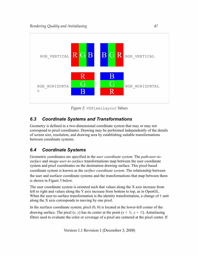
Rendering Quality and Antialiasing 47
Figure 2: VGPixelLayout Values
6.3 Coordinate Systems and TransformationsGeometry is defined in a two-dimensional coordinate system that may or may not correspond to pixel coordinates. Drawing may be performed independently of the details of screen size, resolution, and drawing area by establishing suitable transformations between coordinate systems.
6.4 Coordinate SystemsGeometric coordinates are specified in the user coordinate system. The path-user-to-surface and image-user-to-surface transformations map between the user coordinate system and pixel coordinates on the destination drawing surface. This pixel-based coordinate system is known as the surface coordinate system. The relationship between the user and surface coordinate systems and the transformations that map between them is shown in Figure 3 below.
The user coordinate system is oriented such that values along the X axis increase from left to right and values along the Y axis increase from bottom to top, as in OpenGL. When the user-to-surface transformation is the identity transformation, a change of 1 unit along the X axis corresponds to moving by one pixel.
In the surface coordinate system, pixel (0, 0) is located at the lower-left corner of the drawing surface. The pixel (x, y) has its center at the point (x + ½, y + ½). Antialiasing filters used to evaluate the color or coverage of a pixel are centered at the pixel center. If
Version 1.1 Revision 1 (December 3, 2008)
R G B B G R
RGB
BGR
RGB_VERTICAL BGR_VERTICAL
RGB_HORIZONTAL
BGR_HORIZONTAL
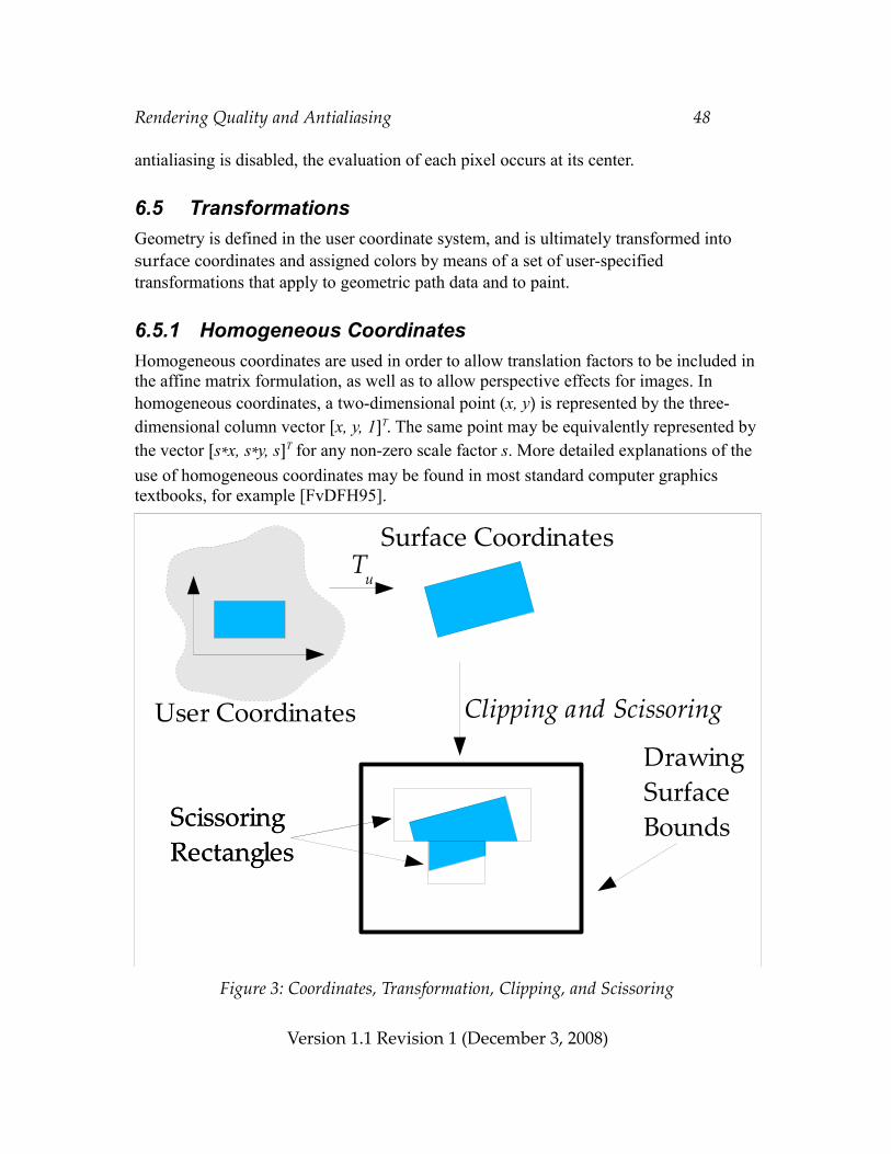
Rendering Quality and Antialiasing 48
antialiasing is disabled, the evaluation of each pixel occurs at its center.
6.5 TransformationsGeometry is defined in the user coordinate system, and is ultimately transformed into surface coordinates and assigned colors by means of a set of user-specified transformations that apply to geometric path data and to paint.
6.5.1 Homogeneous CoordinatesHomogeneous coordinates are used in order to allow translation factors to be included in the affine matrix formulation, as well as to allow perspective effects for images. In homogeneous coordinates, a two-dimensional point (x, y) is represented by the three-dimensional column vector [x, y, 1]T. The same point may be equivalently represented by the vector [s*x, s*y, s]T for any non-zero scale factor s. More detailed explanations of the use of homogeneous coordinates may be found in most standard computer graphics textbooks, for example [FvDFH95].
Figure 3: Coordinates, Transformation, Clipping, and Scissoring
Version 1.1 Revision 1 (December 3, 2008)
Tu
User Coordinates
Surface Coordinates
ScissoringRectangles
Clipping and Scissoring
ScissoringRectangles
Drawing Surface Bounds
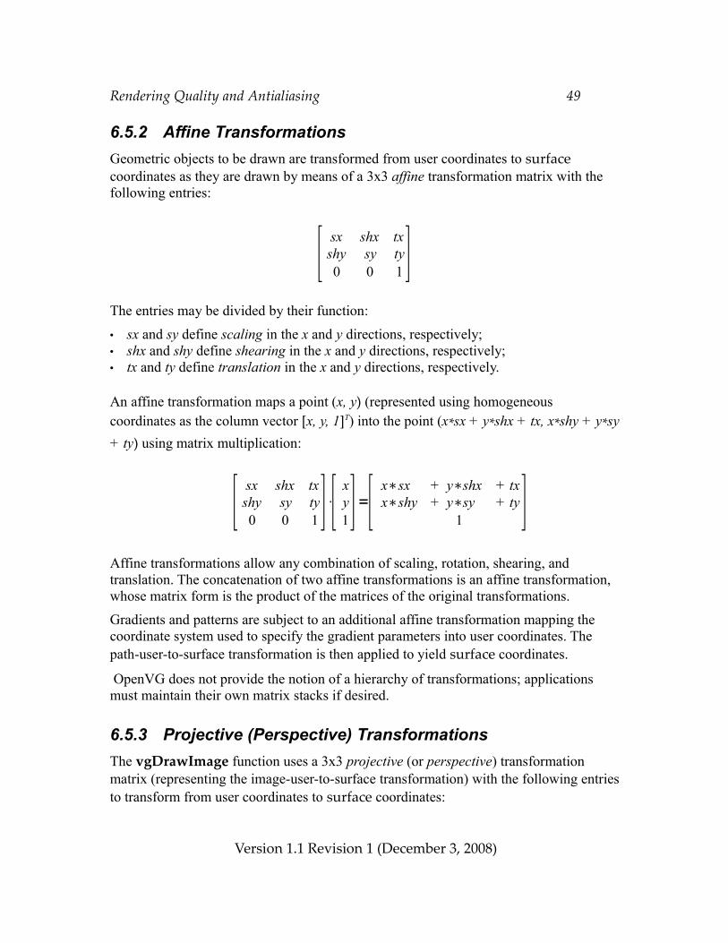
Rendering Quality and Antialiasing 49
6.5.2 Affine TransformationsGeometric objects to be drawn are transformed from user coordinates to surface coordinates as they are drawn by means of a 3x3 affine transformation matrix with the following entries:
The entries may be divided by their function:
• sx and sy define scaling in the x and y directions, respectively;• shx and shy define shearing in the x and y directions, respectively;• tx and ty define translation in the x and y directions, respectively.
An affine transformation maps a point (x, y) (represented using homogeneous coordinates as the column vector [x, y, 1]T) into the point (x*sx + y*shx + tx, x*shy + y*sy + ty) using matrix multiplication:
Affine transformations allow any combination of scaling, rotation, shearing, and translation. The concatenation of two affine transformations is an affine transformation, whose matrix form is the product of the matrices of the original transformations.
Gradients and patterns are subject to an additional affine transformation mapping the coordinate system used to specify the gradient parameters into user coordinates. The path-user-to-surface transformation is then applied to yield surface coordinates.
OpenVG does not provide the notion of a hierarchy of transformations; applications must maintain their own matrix stacks if desired.
6.5.3 Projective (Perspective) TransformationsThe vgDrawImage function uses a 3x3 projective (or perspective) transformation matrix (representing the image-user-to-surface transformation) with the following entries to transform from user coordinates to surface coordinates:
Version 1.1 Revision 1 (December 3, 2008)
[ sx shx txshy sy ty0 0 1 ]
[ sx shx txshy sy ty0 0 1 ]⋅[ x
y1]=[ x∗sx + y∗shx + tx
x∗shy + y∗sy + ty1 ]
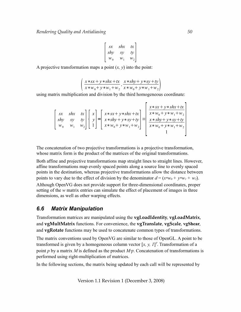
Rendering Quality and Antialiasing 50
A projective transformation maps a point (x, y) into the point:
using matrix multiplication and division by the third homogeneous coordinate:
The concatenation of two projective transformations is a projective transformation, whose matrix form is the product of the matrices of the original transformations.
Both affine and projective transformations map straight lines to straight lines. However, affine transformations map evenly spaced points along a source line to evenly spaced points in the destination, whereas projective transformations allow the distance between points to vary due to the effect of division by the denominator d = (x*w0 + y*w1 + w2). Although OpenVG does not provide support for three-dimensional coordinates, proper setting of the w matrix entries can simulate the effect of placement of images in three dimensions, as well as other warping effects.
6.6 Matrix ManipulationTransformation matrices are manipulated using the vgLoadIdentity, vgLoadMatrix, and vgMultMatrix functions. For convenience, the vgTranslate, vgScale, vgShear, and vgRotate functions may be used to concatenate common types of transformations.
The matrix conventions used by OpenVG are similar to those of OpenGL. A point to be transformed is given by a homogeneous column vector [x, y, 1]T. Transformation of a point p by a matrix M is defined as the product M∙p. Concatenation of transformations is performed using right-multiplication of matrices.
In the following sections, the matrix being updated by each call will be represented by
Version 1.1 Revision 1 (December 3, 2008)
[ sx shx txshy sy tyw0 w1 w2
]
[ sx shx txshy sy tyw0 w1 w2
]⋅[ xy1 ]=[ x∗sx y∗shxtx
x∗shy y∗sytyx∗w0 y∗w1w2
]≡[x∗sx y∗shxtxx∗w0 y∗w1w2
x∗shy y∗sytyx∗w0 y∗w1w2
1]
x∗sx y∗shxtxx∗w0 y∗w1w2
, x∗shy y∗sytyx∗w0 y∗w 1w 2
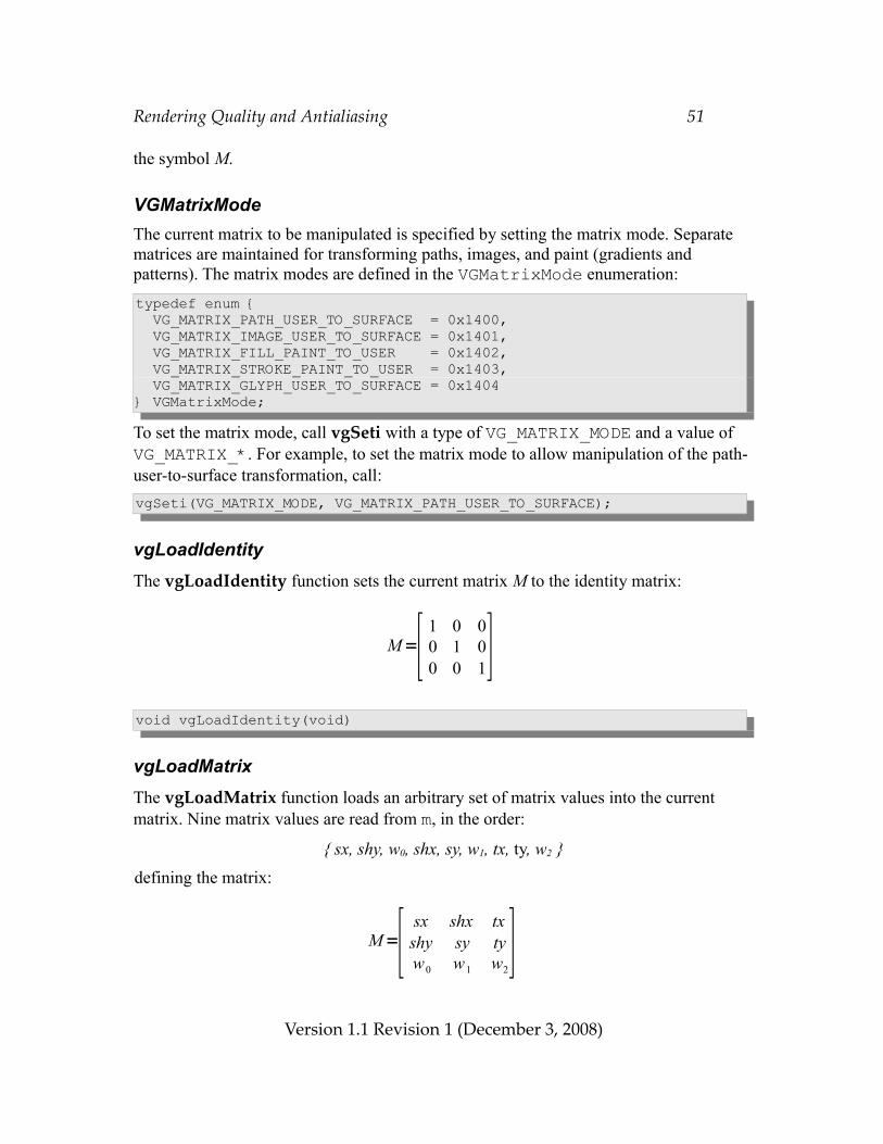
Rendering Quality and Antialiasing 51
the symbol M.
VGMatrixModeThe current matrix to be manipulated is specified by setting the matrix mode. Separate matrices are maintained for transforming paths, images, and paint (gradients and patterns). The matrix modes are defined in the VGMatrixMode enumeration:typedef enum { VG_MATRIX_PATH_USER_TO_SURFACE = 0x1400, VG_MATRIX_IMAGE_USER_TO_SURFACE = 0x1401, VG_MATRIX_FILL_PAINT_TO_USER = 0x1402, VG_MATRIX_STROKE_PAINT_TO_USER = 0x1403, VG_MATRIX_GLYPH_USER_TO_SURFACE = 0x1404} VGMatrixMode;
To set the matrix mode, call vgSeti with a type of VG_MATRIX_MODE and a value of VG_MATRIX_*. For example, to set the matrix mode to allow manipulation of the path-user-to-surface transformation, call:vgSeti(VG_MATRIX_MODE, VG_MATRIX_PATH_USER_TO_SURFACE);
vgLoadIdentityThe vgLoadIdentity function sets the current matrix M to the identity matrix:
void vgLoadIdentity(void)
vgLoadMatrixThe vgLoadMatrix function loads an arbitrary set of matrix values into the current matrix. Nine matrix values are read from m, in the order:
{ sx, shy, w0, shx, sy, w1, tx, ty, w2 }defining the matrix:
Version 1.1 Revision 1 (December 3, 2008)
M=[ 1 0 00 1 00 0 1]
M=[ sx shx txshy sy tyw0 w1 w2
]
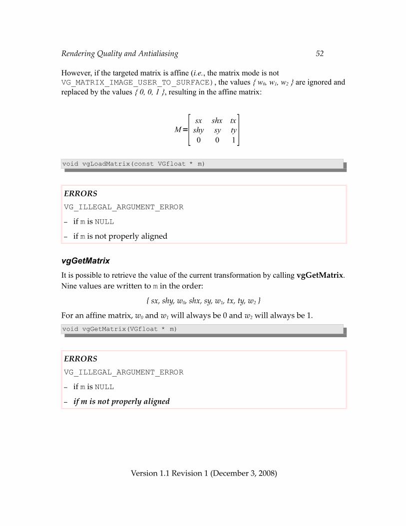
Rendering Quality and Antialiasing 52
However, if the targeted matrix is affine (i.e., the matrix mode is not VG_MATRIX_IMAGE_USER_TO_SURFACE), the values { w0, w1, w2 } are ignored and replaced by the values { 0, 0, 1 }, resulting in the affine matrix:
void vgLoadMatrix(const VGfloat * m)
ERRORSVG_ILLEGAL_ARGUMENT_ERROR– if m is NULL– if m is not properly aligned
vgGetMatrixIt is possible to retrieve the value of the current transformation by calling vgGetMatrix. Nine values are written to m in the order:
{ sx, shy, w0, shx, sy, w1, tx, ty, w2 }
For an affine matrix, w0 and w1 will always be 0 and w2 will always be 1.void vgGetMatrix(VGfloat * m)
ERRORSVG_ILLEGAL_ARGUMENT_ERROR– if m is NULL– if m is not properly aligned
Version 1.1 Revision 1 (December 3, 2008)
M=[ sx shx txshy sy ty0 0 1 ]
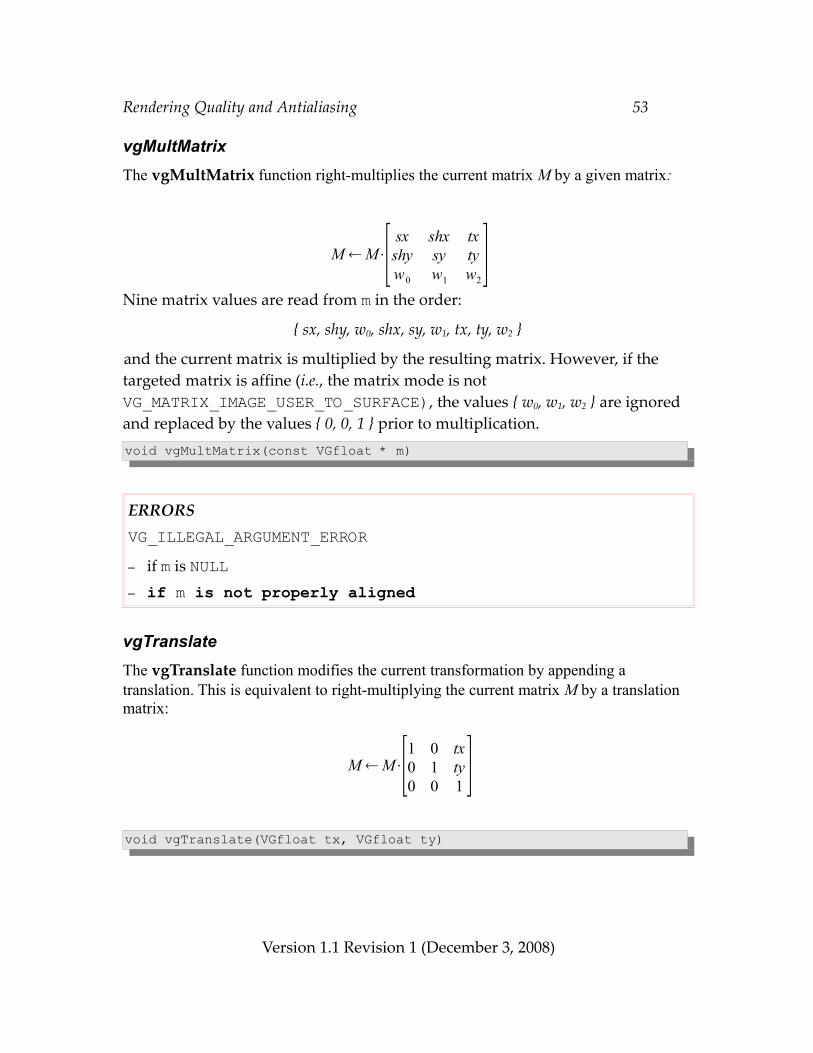
Rendering Quality and Antialiasing 53
vgMultMatrixThe vgMultMatrix function right-multiplies the current matrix M by a given matrix:
Nine matrix values are read from m in the order:
{ sx, shy, w0, shx, sy, w1, tx, ty, w2 }
and the current matrix is multiplied by the resulting matrix. However, if the targeted matrix is affine (i.e., the matrix mode is not VG_MATRIX_IMAGE_USER_TO_SURFACE), the values { w0, w1, w2 } are ignored and replaced by the values { 0, 0, 1 } prior to multiplication.void vgMultMatrix(const VGfloat * m)
ERRORSVG_ILLEGAL_ARGUMENT_ERROR– if m is NULL– if m is not properly aligned
vgTranslateThe vgTranslate function modifies the current transformation by appending a translation. This is equivalent to right-multiplying the current matrix M by a translation matrix:
void vgTranslate(VGfloat tx, VGfloat ty)
Version 1.1 Revision 1 (December 3, 2008)
M M⋅[1 0 tx0 1 ty0 0 1 ]
M M⋅[ sx shx txshy sy tyw0 w1 w2
]
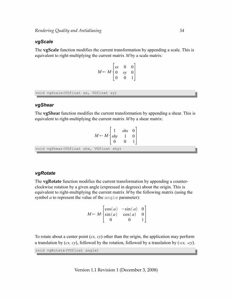
Rendering Quality and Antialiasing 54
vgScaleThe vgScale function modifies the current transformation by appending a scale. This is equivalent to right-multiplying the current matrix M by a scale matrix:
void vgScale(VGfloat sx, VGfloat sy)
vgShearThe vgShear function modifies the current transformation by appending a shear. This is equivalent to right-multiplying the current matrix M by a shear matrix:
void vgShear(VGfloat shx, VGfloat shy)
vgRotateThe vgRotate function modifies the current transformation by appending a counter-clockwise rotation by a given angle (expressed in degrees) about the origin. This is equivalent to right-multiplying the current matrix M by the following matrix (using the symbol a to represent the value of the angle parameter):
To rotate about a center point (cx, cy) other than the origin, the application may perform a translation by (cx, cy), followed by the rotation, followed by a translation by (-cx, -cy).void vgRotate(VGfloat angle)
Version 1.1 Revision 1 (December 3, 2008)
M M⋅[sx 0 00 sy 00 0 1]
M M⋅[cosa −sin a 0sin a cos a 0
0 0 1 ]
M M⋅[ 1 shx 0shy 1 00 0 1]
Scissoring, Masking, and Clearing 55
7 Scissoring, Masking, and ClearingAll drawing is clipped (restricted) to the bounds of the drawing surface, and may be further clipped to the interior of a set of scissoring rectangles. If available, a mask is applied for further clipping and to create soft edge and partial transparency effects.
Pixels outside the drawing surface bounds, or (when scissoring is enabled) not in any scissoring rectangle are not affected by any drawing operation. For any drawing operation, each pixel will receive the same value for any setting of the scissoring rectangles that contains the pixel. That is, the placement of the scissoring rectangles, and whether scissoring is enabled, affects only whether a given pixel will be written, without affecting what value it will receive.
7.1 ScissoringDrawing may be restricted to the union of a set of scissoring rectangles. Scissoring is enabled when the parameter VG_SCISSORING has the value VG_TRUE. Scissoring may be disabled by calling vgSeti with a paramType argument of VG_SCISSORING and a value of VG_FALSE.
VG_MAX_SCISSOR_RECTSThe VG_MAX_SCISSOR_RECTS parameter contains the maximum number of scissoring rectangles that may be supplied for the VG_SCISSOR_RECTS parameter. All implementations must support at least 32 scissor rectangles. If there is no implementation-defined limit, a value of VG_MAXINT may be returned. The value may be retrieved by calling vgGeti with a paramType argument of VG_MAX_SCISSOR_RECTS:VGint maxScissorRects = vgGeti(VG_MAX_SCISSOR_RECTS);
Specifying Scissoring RectanglesEach scissoring rectangle is specified as an integer 4-tuple of the form (minX, minY, width, height), where minX and minY are inclusive. A rectangle with width ≤ 0 or height ≤ 0 is ignored. The scissoring region is defined as the union of all the specified rectangles. The rectangles as specified need not be disjoint. If scissoring is enabled and no valid scissoring rectangles are present, no drawing occurs. If more than VG_MAX_SCISSOR_RECTS rectangles are specified, those beyond the first VG_MAX_SCISSOR_RECTS are discarded immediately (and will not be returned by vgGet).
Version 1.1 Revision 1 (December 3, 2008)
Scissoring, Masking, and Clearing 56
#define NUM_RECTS 2/* { Min X, Min Y, Width, Height } 4-Tuples */VGint coords[4*NUM_RECTS] = { 20, 30, 100, 200, 50, 70, 80, 80 };vgSetiv(VG_SCISSOR_RECTS, 4*NUM_RECTS, coords)
7.2 Masking All drawing operations may be modified by a drawing surface mask (also known as an alpha mask for historical reasons), which is a separate implementation-internal buffer defining an additional coverage value at each sample of the drawing surface. The values from this buffer modify the coverage value computed by the rasterization stage of the pipeline.
Masking is enabled when a mask is present for the drawing surface (e.g., by specifying an EGLConfig with an EGL_ALPHA_MASK_SIZE attribute having a value greater than zero) and the VG_MASKING parameter has the value VG_TRUE. Masking may be disabled by calling vgSeti with a parameter of VG_MASKING and a value of VG_FALSE. If a drawing surface mask is present, it may be manipulated by the vgMask function regardless of the value of VG_MASKING at the time of the call. If a drawing surface mask is not present, the behavior is the same as though there were a mask having a value of 1 at every pixel; functions that manipulate the mask values have no effect.
In addition to the drawing surface mask, OpenVG applications may manipulate mask layer objects, which are application-level objects accessed via handles. The term layer is not meant to imply any ordering between such objects; rather, it is up to the application to modify the drawing surface mask using mask layer objects in order to affect the rendering process. A mask layer that is created when a multisampled drawing surface is current may only be used to modify that drawing surface's mask or other drawing surface masks that share the same bit depth and subpixel sample layout.
In this section, we will describe coverage values as ranging from 0 to 1. The actual bit depth used for computation is implementation-dependent. For single-sampled surfaces, it must be possible to obtain configurations supporting a mask with at least 1 bit for 1-bit black and white drawing surfaces, a mask with at least 4 bits for 16-bit color drawing surfaces, and a mask with at least 8 bits for 8-bit grayscale and 24-bit color drawing surfaces. For multi-sampled surfaces, implementations are only required to provide 1 mask bit per sample.
Version 1.1 Revision 1 (December 3, 2008)
Scissoring, Masking, and Clearing 57
The drawing surface mask may be thought of as a single-channel image with the same size as the current drawing surface. Initially, the mask has the value of 1 at every pixel. Changes to the mask outside of its bounds are ignored. If the drawing surface size changes, the drawing surface mask associated with it is resized accordingly, with new pixels being initialized to a coverage value of 1. If the context acquires a new drawing surface, the drawing surface mask is reset. Some implementations may modify primitive drawing using the path geometry used to generate the mask directly, without first rasterizing such geometry into a pixel-based representation.
A mask defines a stencil area through which primitives are placed before being drawn. The union, intersection, and subtraction operations on masks are defined by analogy with the corresponding operations on the stencil areas.
The mask coverage values are multiplied by the corresponding coverage values of each primitive being drawn in the clipping and masking stage (stage 5) of the rendering pipeline (see Section 2.5). The masking step is equivalent (except for color space conversions that may occur) to replacing the source image with the result of the Porter-Duff operation “Src in Mask” (see Section 13.3).
VGMaskOperationThe VGMaskOperation enumeration defines the set of possible operations that may be used to modify a mask, possibly making use of a new mask image. Each operation occurs within a rectangular region of interest.
The VG_CLEAR_MASK operation sets all mask values in the region of interest to 0, ignoring the new mask image.
The VG_FILL_MASK operation sets all mask values in the region of interest to 1, ignoring the new mask image.
The VG_SET_MASK operation copies values in the region of interest from the new mask image, overwriting the previous mask values.
The VG_UNION_MASK operation replaces the previous mask in the region of interest by its union with the new mask image. The resulting values are always greater than or equal to their previous value.
The VG_INTERSECT_MASK operation replaces the previous mask in the region of interest by its intersection with the new mask image. The resulting mask values are always less than or equal to their previous value.
Version 1.1 Revision 1 (December 3, 2008)
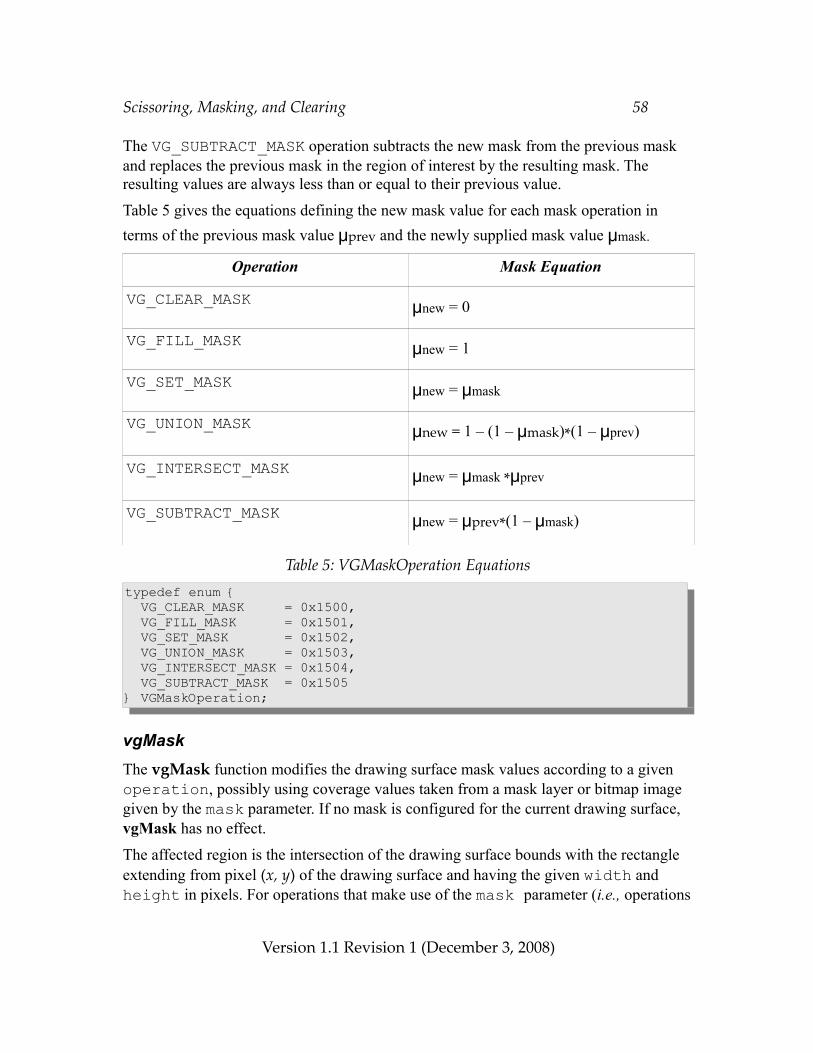
Scissoring, Masking, and Clearing 58
The VG_SUBTRACT_MASK operation subtracts the new mask from the previous mask and replaces the previous mask in the region of interest by the resulting mask. The resulting values are always less than or equal to their previous value.
Table 5 gives the equations defining the new mask value for each mask operation in terms of the previous mask value μprev and the newly supplied mask value μmask.
Operation Mask Equation
VG_CLEAR_MASK μnew = 0
VG_FILL_MASK μnew = 1
VG_SET_MASK μnew = μmask
VG_UNION_MASK μnew = 1 – (1 – μmask)*(1 – μprev)
VG_INTERSECT_MASK μnew = μmask *μprev
VG_SUBTRACT_MASK μnew = μprev*(1 – μmask)
Table 5: VGMaskOperation Equationstypedef enum { VG_CLEAR_MASK = 0x1500, VG_FILL_MASK = 0x1501, VG_SET_MASK = 0x1502, VG_UNION_MASK = 0x1503, VG_INTERSECT_MASK = 0x1504, VG_SUBTRACT_MASK = 0x1505} VGMaskOperation;
vgMaskThe vgMask function modifies the drawing surface mask values according to a given operation, possibly using coverage values taken from a mask layer or bitmap image given by the mask parameter. If no mask is configured for the current drawing surface, vgMask has no effect.
The affected region is the intersection of the drawing surface bounds with the rectangle extending from pixel (x, y) of the drawing surface and having the given width and height in pixels. For operations that make use of the mask parameter (i.e., operations
Version 1.1 Revision 1 (December 3, 2008)
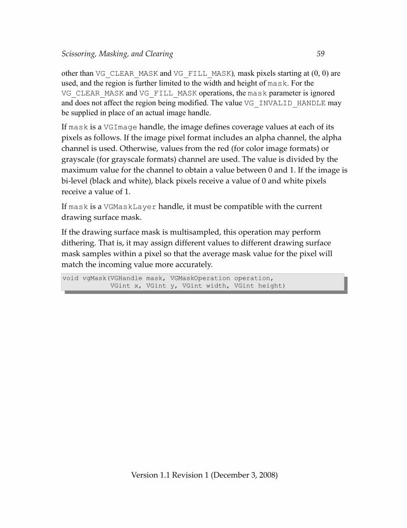
Scissoring, Masking, and Clearing 59
other than VG_CLEAR_MASK and VG_FILL_MASK), mask pixels starting at (0, 0) are used, and the region is further limited to the width and height of mask. For the VG_CLEAR_MASK and VG_FILL_MASK operations, the mask parameter is ignored and does not affect the region being modified. The value VG_INVALID_HANDLE may be supplied in place of an actual image handle.
If mask is a VGImage handle, the image defines coverage values at each of its pixels as follows. If the image pixel format includes an alpha channel, the alpha channel is used. Otherwise, values from the red (for color image formats) or grayscale (for grayscale formats) channel are used. The value is divided by the maximum value for the channel to obtain a value between 0 and 1. If the image is bi-level (black and white), black pixels receive a value of 0 and white pixels receive a value of 1.
If mask is a VGMaskLayer handle, it must be compatible with the current drawing surface mask.
If the drawing surface mask is multisampled, this operation may perform dithering. That is, it may assign different values to different drawing surface mask samples within a pixel so that the average mask value for the pixel will match the incoming value more accurately.void vgMask(VGHandle mask, VGMaskOperation operation, VGint x, VGint y, VGint width, VGint height)
Version 1.1 Revision 1 (December 3, 2008)
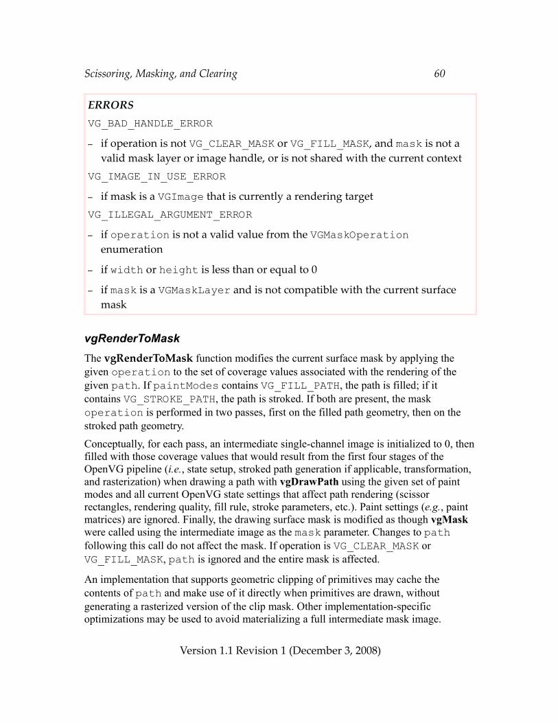
Scissoring, Masking, and Clearing 60
ERRORSVG_BAD_HANDLE_ERROR– if operation is not VG_CLEAR_MASK or VG_FILL_MASK, and mask is not a
valid mask layer or image handle, or is not shared with the current contextVG_IMAGE_IN_USE_ERROR– if mask is a VGImage that is currently a rendering targetVG_ILLEGAL_ARGUMENT_ERROR– if operation is not a valid value from the VGMaskOperation
enumeration
– if width or height is less than or equal to 0
– if mask is a VGMaskLayer and is not compatible with the current surface mask
vgRenderToMaskThe vgRenderToMask function modifies the current surface mask by applying the given operation to the set of coverage values associated with the rendering of the given path. If paintModes contains VG_FILL_PATH, the path is filled; if it contains VG_STROKE_PATH, the path is stroked. If both are present, the mask operation is performed in two passes, first on the filled path geometry, then on the stroked path geometry.
Conceptually, for each pass, an intermediate single-channel image is initialized to 0, then filled with those coverage values that would result from the first four stages of the OpenVG pipeline (i.e., state setup, stroked path generation if applicable, transformation, and rasterization) when drawing a path with vgDrawPath using the given set of paint modes and all current OpenVG state settings that affect path rendering (scissor rectangles, rendering quality, fill rule, stroke parameters, etc.). Paint settings (e.g., paint matrices) are ignored. Finally, the drawing surface mask is modified as though vgMask were called using the intermediate image as the mask parameter. Changes to path following this call do not affect the mask. If operation is VG_CLEAR_MASK or VG_FILL_MASK, path is ignored and the entire mask is affected.
An implementation that supports geometric clipping of primitives may cache the contents of path and make use of it directly when primitives are drawn, without generating a rasterized version of the clip mask. Other implementation-specific optimizations may be used to avoid materializing a full intermediate mask image.
Version 1.1 Revision 1 (December 3, 2008)
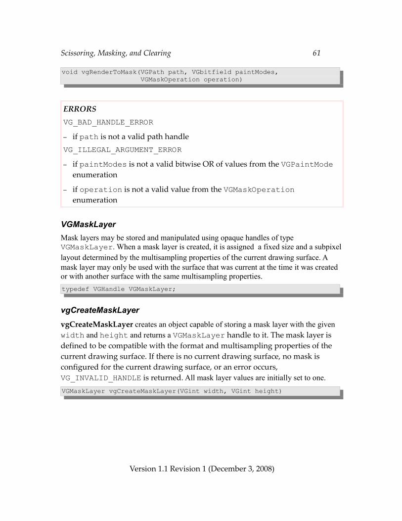
Scissoring, Masking, and Clearing 61
void vgRenderToMask(VGPath path, VGbitfield paintModes, VGMaskOperation operation)
ERRORSVG_BAD_HANDLE_ERROR– if path is not a valid path handleVG_ILLEGAL_ARGUMENT_ERROR– if paintModes is not a valid bitwise OR of values from the VGPaintMode
enumeration
– if operation is not a valid value from the VGMaskOperation enumeration
VGMaskLayerMask layers may be stored and manipulated using opaque handles of type VGMaskLayer. When a mask layer is created, it is assigned a fixed size and a subpixel layout determined by the multisampling properties of the current drawing surface. A mask layer may only be used with the surface that was current at the time it was created or with another surface with the same multisampling properties.typedef VGHandle VGMaskLayer;
vgCreateMaskLayervgCreateMaskLayer creates an object capable of storing a mask layer with the given width and height and returns a VGMaskLayer handle to it. The mask layer is defined to be compatible with the format and multisampling properties of the current drawing surface. If there is no current drawing surface, no mask is configured for the current drawing surface, or an error occurs, VG_INVALID_HANDLE is returned. All mask layer values are initially set to one.VGMaskLayer vgCreateMaskLayer(VGint width, VGint height)
Version 1.1 Revision 1 (December 3, 2008)
Scissoring, Masking, and Clearing 62
ERRORSVG_ILLEGAL_ARGUMENT_ERROR– if width or height are less than or equal to 0
– if width is greater than VG_MAX_IMAGE_WIDTH– if height is greater than VG_MAX_IMAGE_HEIGHT– if width*height is greater than VG_MAX_IMAGE_PIXELS
vgDestroyMaskLayerThe resources associated with a mask layer may be deallocated by calling vgDestroyMaskLayer. Following the call, the maskLayer handle is no longer valid in the current context.void vgDestroyMaskLayer(VGMaskLayer maskLayer)
ERRORSVG_BAD_HANDLE_ERROR– if maskLayer is not a valid mask handle
vgFillMaskLayerThe vgFillMaskLayer function sets the values of a given maskLayer within a given rectangular region to a given value. The floating-point value value must be between 0 and 1. The value is rounded to the closest available value supported by the mask layer. If two values are equally close, the larger value is used.void vgFillMaskLayer(VGMaskLayer maskLayer, VGint x, VGint y, VGint width, VGint height, VGfloat value)
Version 1.1 Revision 1 (December 3, 2008)
Scissoring, Masking, and Clearing 63
ERRORSVG_BAD_HANDLE_ERROR– if maskLayer is not a valid mask layer handle, or is not shared with the
current contextVG_ILLEGAL_ARGUMENT_ERROR– if value is less than 0 or greater than 1
– if width or height is less than or equal to 0
– if x or y is less than 0
– if x + width is greater than the width of the mask
– if y + height is greater than the height of the mask
vgCopyMaskvgCopyMask copies a portion of the current surface mask into a VGMaskLayer object. The source region starts at (sx, sy) in the surface mask, and the destination region starts at (dx, dy) in the destination maskLayer. The copied region is clipped to the given width and height and the bounds of the source and destination. If the current context does not contain a surface mask, vgCopyMask does nothing.void vgCopyMask(VGMaskLayer maskLayer, VGint dx, VGint dy, VGint sx, VGint sy, VGint width, VGint height)
ERRORSVG_BAD_HANDLE_ERROR– if maskLayer is not a valid mask layer handleVG_ILLEGAL_ARGUMENT_ERROR– if width or height are less than or equal to 0
– if maskLayer is not compatible with the current surface mask
Version 1.1 Revision 1 (December 3, 2008)
Scissoring, Masking, and Clearing 64
7.3 Fast ClearingThe vgClear function allows a region of pixels to be set to a single color with a single call.
vgClearThe vgClear function fills the portion of the drawing surface intersecting the rectangle extending from pixel (x, y) and having the given width and height with a constant color value, taken from the VG_CLEAR_COLOR parameter. The color value is expressed in non-premultiplied sRGBA (sRGB color plus alpha)format. Values outside the [0, 1] range are interpreted as the nearest endpoint of the range. The color is converted to the destination color space in the same manner as if a rectangular path were being filled. Clipping and scissoring take place in the usual fashion, but antialiasing, masking, and blending do not occur.void vgClear(VGint x, VGint y, VGint width, VGint height)
ERRORSVG_ILLEGAL_ARGUMENT_ERROR– if width or height is less than or equal to 0
For example, to set the entire drawing surface with dimensions WIDTH and HEIGHT to an opaque yellow color, the following code could be used:VGfloat color[4] = { 1.0f, 1.0f, 0.0f, 1.0f }; /* Opaque yellow */
vgSeti(VG_SCISSORING, VG_FALSE);vgSetfv(VG_CLEAR_COLOR, 4, color);vgClear(0, 0, WIDTH, HEIGHT);
8 PathsPaths are the heart of the OpenVG API. All geometry to be drawn must be defined in terms of one or more paths. Paths are defined by a sequence of segment commands (or segments). Each segment command in the standard format may specify a move, a straight line segment, a quadratic or cubic Bézier segment, or an elliptical arc. Extensions may define other segment types.
Version 1.1 Revision 1 (December 3, 2008)
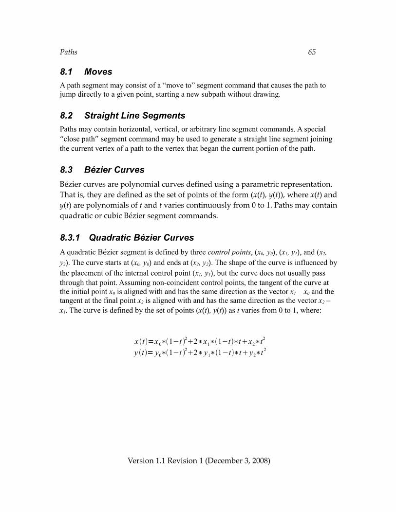
Paths 65
8.1 MovesA path segment may consist of a “move to” segment command that causes the path to jump directly to a given point, starting a new subpath without drawing.
8.2 Straight Line SegmentsPaths may contain horizontal, vertical, or arbitrary line segment commands. A special “close path” segment command may be used to generate a straight line segment joining the current vertex of a path to the vertex that began the current portion of the path.
8.3 Bézier CurvesBézier curves are polynomial curves defined using a parametric representation. That is, they are defined as the set of points of the form (x(t), y(t)), where x(t) and y(t) are polynomials of t and t varies continuously from 0 to 1. Paths may contain quadratic or cubic Bézier segment commands.
8.3.1 Quadratic Bézier CurvesA quadratic Bézier segment is defined by three control points, (x0, y0), (x1, y1), and (x2, y2). The curve starts at (x0, y0) and ends at (x2, y2). The shape of the curve is influenced by the placement of the internal control point (x1, y1), but the curve does not usually pass through that point. Assuming non-coincident control points, the tangent of the curve at the initial point x0 is aligned with and has the same direction as the vector x1 – x0 and the tangent at the final point x2 is aligned with and has the same direction as the vector x2 – x1. The curve is defined by the set of points (x(t), y(t)) as t varies from 0 to 1, where:
Version 1.1 Revision 1 (December 3, 2008)
x t =x 0∗1−t 22∗x1∗1−t ∗tx2∗t2
y t = y0∗1−t 22∗y1∗1−t ∗t y2∗t 2
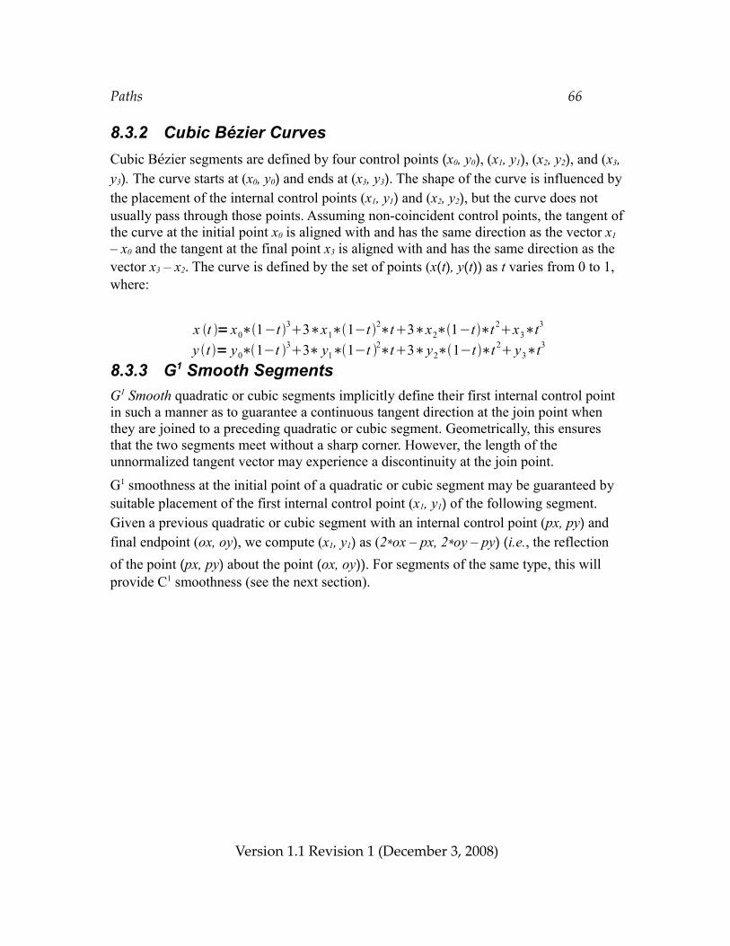
Paths 66
8.3.2 Cubic Bézier CurvesCubic Bézier segments are defined by four control points (x0, y0), (x1, y1), (x2, y2), and (x3, y3). The curve starts at (x0, y0) and ends at (x3, y3). The shape of the curve is influenced by the placement of the internal control points (x1, y1) and (x2, y2), but the curve does not usually pass through those points. Assuming non-coincident control points, the tangent of the curve at the initial point x0 is aligned with and has the same direction as the vector x1
– x0 and the tangent at the final point x3 is aligned with and has the same direction as the vector x3 – x2. The curve is defined by the set of points (x(t), y(t)) as t varies from 0 to 1, where:
8.3.3 G1 Smooth SegmentsG1 Smooth quadratic or cubic segments implicitly define their first internal control point in such a manner as to guarantee a continuous tangent direction at the join point when they are joined to a preceding quadratic or cubic segment. Geometrically, this ensures that the two segments meet without a sharp corner. However, the length of the unnormalized tangent vector may experience a discontinuity at the join point.
G1 smoothness at the initial point of a quadratic or cubic segment may be guaranteed by suitable placement of the first internal control point (x1, y1) of the following segment. Given a previous quadratic or cubic segment with an internal control point (px, py) and final endpoint (ox, oy), we compute (x1, y1) as (2*ox – px, 2*oy – py) (i.e., the reflection of the point (px, py) about the point (ox, oy)). For segments of the same type, this will provide C1 smoothness (see the next section).
Version 1.1 Revision 1 (December 3, 2008)
x t = x0∗1−t 33∗x1∗1−t 2∗t3∗x2∗1−t∗t 2x3∗t3
y t = y0∗1−t 33∗ y1∗1−t 2∗t3∗y2∗1−t ∗t 2 y3∗t3
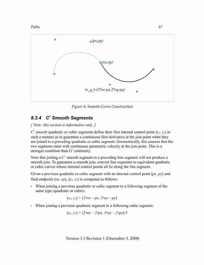
Paths 67
Figure 4: Smooth Curve Construction
8.3.4 C1 Smooth Segments[ Note: this section is informative only. ]
C1 smooth quadratic or cubic segments define their first internal control point (x1, y1) in such a manner as to guarantee a continuous first derivative at the join point when they are joined to a preceding quadratic or cubic segment. Geometrically, this ensures that the two segments meet with continuous parametric velocity at the join point. This is a stronger condition than G1 continuity.
Note that joining a C1 smooth segment to a preceding line segment will not produce a smooth join. To guarantee a smooth join, convert line segments to equivalent quadratic or cubic curves whose internal control points all lie along the line segment.
Given a previous quadratic or cubic segment with an internal control point (px, py) and final endpoint (ox, oy), (x1, y1) is computed as follows:
• When joining a previous quadratic or cubic segment to a following segment of the same type (quadratic or cubic):
(x1, y1) = (2*ox – px, 2*oy – py)
• When joining a previous quadratic segment to a following cubic segment:
(x1, y1) = (5*ox – 2*px, 5*oy – 2*py)/3
Version 1.1 Revision 1 (December 3, 2008)
(px,py)
(ox,oy)
(x1,y
1)=(2*ox-px,2*oy-py)
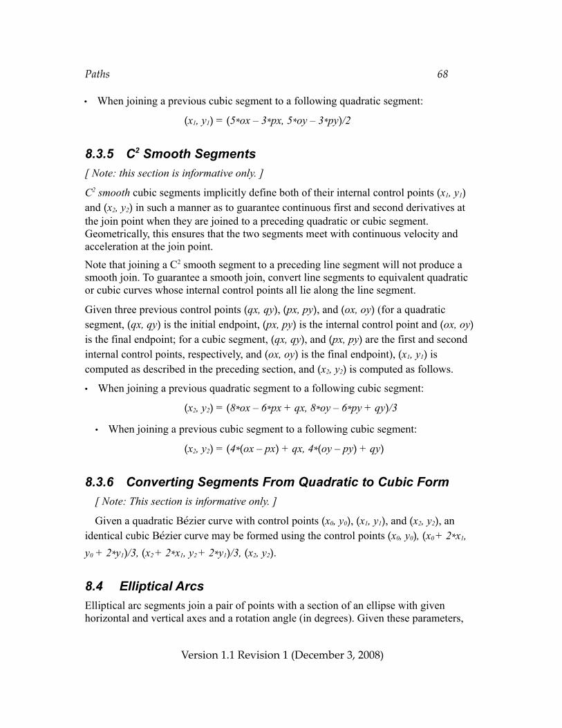
Paths 68
• When joining a previous cubic segment to a following quadratic segment:
(x1, y1) = (5*ox – 3*px, 5*oy – 3*py)/2
8.3.5 C2 Smooth Segments[ Note: this section is informative only. ]
C2 smooth cubic segments implicitly define both of their internal control points (x1, y1) and (x2, y2) in such a manner as to guarantee continuous first and second derivatives at the join point when they are joined to a preceding quadratic or cubic segment. Geometrically, this ensures that the two segments meet with continuous velocity and acceleration at the join point.
Note that joining a C2 smooth segment to a preceding line segment will not produce a smooth join. To guarantee a smooth join, convert line segments to equivalent quadratic or cubic curves whose internal control points all lie along the line segment.
Given three previous control points (qx, qy), (px, py), and (ox, oy) (for a quadratic segment, (qx, qy) is the initial endpoint, (px, py) is the internal control point and (ox, oy) is the final endpoint; for a cubic segment, (qx, qy), and (px, py) are the first and second internal control points, respectively, and (ox, oy) is the final endpoint), (x1, y1) is computed as described in the preceding section, and (x2, y2) is computed as follows.
• When joining a previous quadratic segment to a following cubic segment:
(x2, y2) = (8*ox – 6*px + qx, 8*oy – 6*py + qy)/3
• When joining a previous cubic segment to a following cubic segment:
(x2, y2) = (4*(ox – px) + qx, 4*(oy – py) + qy)
8.3.6 Converting Segments From Quadratic to Cubic Form[ Note: This section is informative only. ]
Given a quadratic Bézier curve with control points (x0, y0), (x1, y1), and (x2, y2), an identical cubic Bézier curve may be formed using the control points (x0, y0), (x0 + 2*x1, y0 + 2*y1)/3, (x2 + 2*x1, y2 + 2*y1)/3, (x2, y2).
8.4 Elliptical ArcsElliptical arc segments join a pair of points with a section of an ellipse with given horizontal and vertical axes and a rotation angle (in degrees). Given these parameters,
Version 1.1 Revision 1 (December 3, 2008)
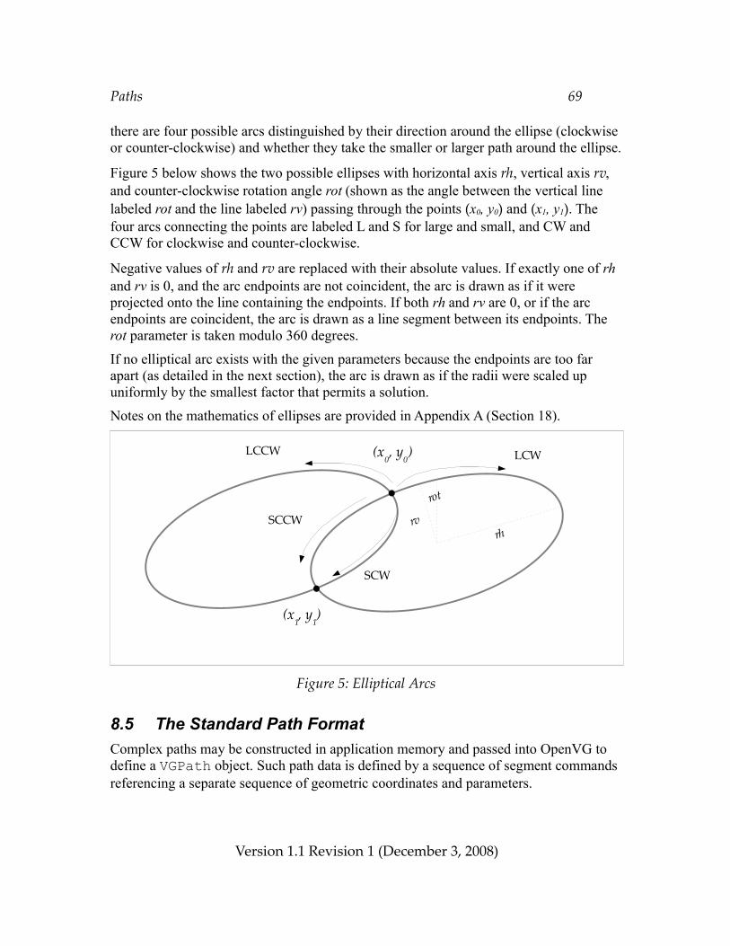
Paths 69
there are four possible arcs distinguished by their direction around the ellipse (clockwise or counter-clockwise) and whether they take the smaller or larger path around the ellipse.
Figure 5 below shows the two possible ellipses with horizontal axis rh, vertical axis rv, and counter-clockwise rotation angle rot (shown as the angle between the vertical line labeled rot and the line labeled rv) passing through the points (x0, y0) and (x1, y1). The four arcs connecting the points are labeled L and S for large and small, and CW and CCW for clockwise and counter-clockwise.
Negative values of rh and rv are replaced with their absolute values. If exactly one of rh and rv is 0, and the arc endpoints are not coincident, the arc is drawn as if it were projected onto the line containing the endpoints. If both rh and rv are 0, or if the arc endpoints are coincident, the arc is drawn as a line segment between its endpoints. The rot parameter is taken modulo 360 degrees.
If no elliptical arc exists with the given parameters because the endpoints are too far apart (as detailed in the next section), the arc is drawn as if the radii were scaled up uniformly by the smallest factor that permits a solution.
Notes on the mathematics of ellipses are provided in Appendix A (Section 18).
Figure 5: Elliptical Arcs
8.5 The Standard Path FormatComplex paths may be constructed in application memory and passed into OpenVG to define a VGPath object. Such path data is defined by a sequence of segment commands referencing a separate sequence of geometric coordinates and parameters.
Version 1.1 Revision 1 (December 3, 2008)
LCCW
SCCW
SCW
LCW
rvrh
rot
(x0, y
0)
(x1, y
1)
Paths 70
In this section, we define the standard data format for paths that may be used to define sequences of various types of path segments. Extensions may define other path data formats.
VG_PATH_FORMAT_STANDARDThe VG_PATH_FORMAT_STANDARD macro defines a constant to be used as an argument to vgCreatePath to indicate that path data are stored using the standard format. As this API is revised, the lower 16 bits of version number may increase. Each version of OpenVG will accept formats defined in all prior specification versions with which it is backwards-compatible.
Extensions wishing to define additional path formats may register for format identifiers that will differ in their upper 16 bits; the lower 16 bits may be used by the extension vendor for versioning purposes.#define VG_PATH_FORMAT_STANDARD 0
8.5.1 Path Segment Command Side EffectsIn order to define the semantics of each segment command type, we define three reference points (all are initially (0, 0)):
• (sx, sy): the beginning of the current subpath, i.e., the position of the last MOVE_TO segment.
• (ox, oy): the last point of the previous segment.
• (px, py): the last internal control point of the previous segment, if the segment was a (regular or smooth) quadratic or cubic Bézier, or else the last point of the previous segment.
Figure 6 illustrates the locations of these points at the end of a sequence of segment commands { MOVE_TO, LINE_TO, CUBIC_TO }.
Version 1.1 Revision 1 (December 3, 2008)
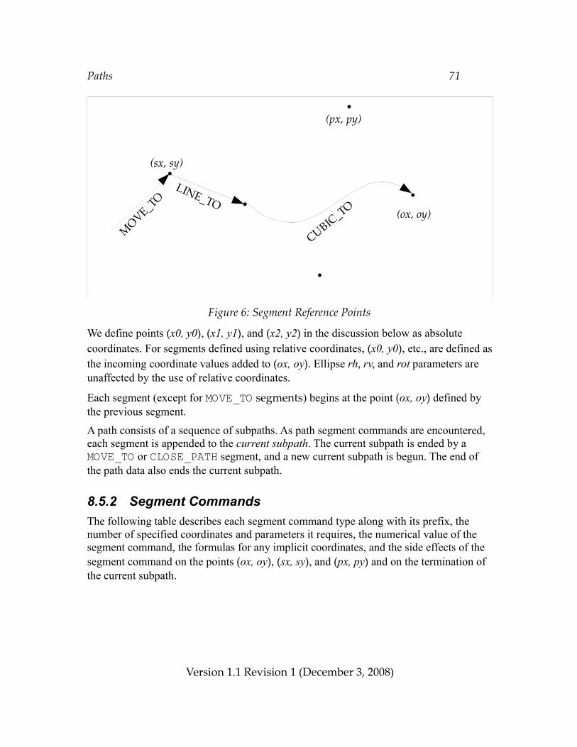
Paths 71
Figure 6: Segment Reference Points
We define points (x0, y0), (x1, y1), and (x2, y2) in the discussion below as absolute coordinates. For segments defined using relative coordinates, (x0, y0), etc., are defined as the incoming coordinate values added to (ox, oy). Ellipse rh, rv, and rot parameters are unaffected by the use of relative coordinates.
Each segment (except for MOVE_TO segments) begins at the point (ox, oy) defined by the previous segment.
A path consists of a sequence of subpaths. As path segment commands are encountered, each segment is appended to the current subpath. The current subpath is ended by a MOVE_TO or CLOSE_PATH segment, and a new current subpath is begun. The end of the path data also ends the current subpath.
8.5.2 Segment CommandsThe following table describes each segment command type along with its prefix, the number of specified coordinates and parameters it requires, the numerical value of the segment command, the formulas for any implicit coordinates, and the side effects of the segment command on the points (ox, oy), (sx, sy), and (px, py) and on the termination of the current subpath.
Version 1.1 Revision 1 (December 3, 2008)
CUBIC_TO
LINE_TO
MOVE_TO
(sx, sy)
(px, py)
(ox, oy)
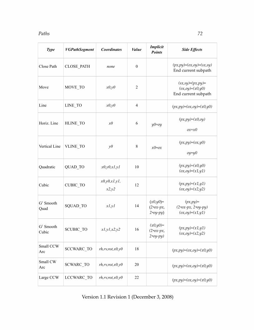
Paths 72
Type VGPathSegment Coordinates Value Implicit Points Side Effects
Close Path CLOSE_PATH none 0 (px,py)=(ox,oy)=(sx,sy)End current subpath
Move MOVE_TO x0,y0 2(sx,sy)=(px,py)=(ox,oy)=(x0,y0)
End current subpath
Line LINE_TO x0,y0 4 (px,py)=(ox,oy)=(x0,y0)
Horiz. Line HLINE_TO x0 6 y0=oy(px,py)=(x0,oy)
ox=x0
Vertical Line VLINE_TO y0 8 x0=ox(px,py)=(ox,y0)
oy=y0
Quadratic QUAD_TO x0,y0,x1,y1 10 (px,py)=(x0,y0)(ox,oy)=(x1,y1)
Cubic CUBIC_TOx0,y0,x1,y1,
x2,y212 (px,py)=(x1,y1)
(ox,oy)=(x2,y2)
G1 SmoothQuad SQUAD_TO x1,y1 14
(x0,y0)=(2*ox-px,2*oy-py)
(px,py)=(2*ox-px, 2*oy-py)
(ox,oy)=(x1,y1)
G1 SmoothCubic SCUBIC_TO x1,y1,x2,y2 16
(x0,y0)=(2*ox-px,2*oy-py)
(px,py)=(x1,y1)(ox,oy)=(x2,y2)
Small CCWArc SCCWARC_TO rh,rv,rot,x0,y0 18 (px,py)=(ox,oy)=(x0,y0)
Small CWArc SCWARC_TO rh,rv,rot,x0,y0 20 (px,py)=(ox,oy)=(x0,y0)
Large CCW LCCWARC_TO rh,rv,rot,x0,y0 22 (px,py)=(ox,oy)=(x0,y0)
Version 1.1 Revision 1 (December 3, 2008)
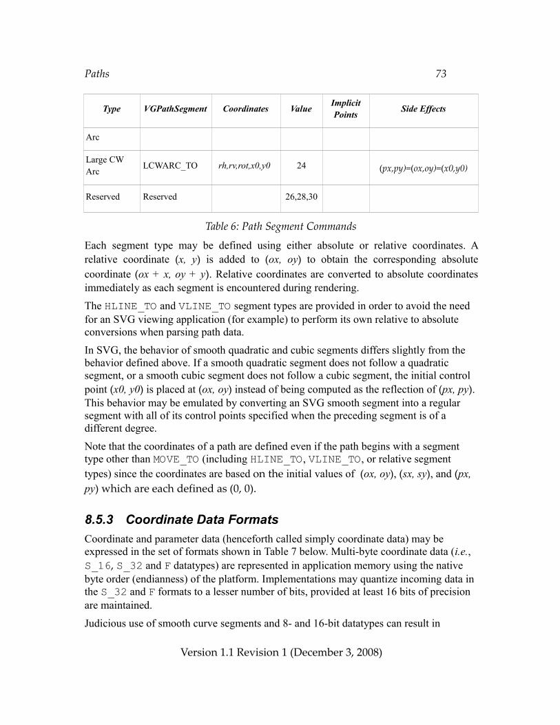
Paths 73
Type VGPathSegment Coordinates Value Implicit Points Side Effects
Arc
Large CWArc LCWARC_TO rh,rv,rot,x0,y0 24 (px,py)=(ox,oy)=(x0,y0)
Reserved Reserved 26,28,30
Table 6: Path Segment Commands
Each segment type may be defined using either absolute or relative coordinates. A relative coordinate (x, y) is added to (ox, oy) to obtain the corresponding absolute coordinate (ox + x, oy + y). Relative coordinates are converted to absolute coordinates immediately as each segment is encountered during rendering.
The HLINE_TO and VLINE_TO segment types are provided in order to avoid the need for an SVG viewing application (for example) to perform its own relative to absolute conversions when parsing path data.
In SVG, the behavior of smooth quadratic and cubic segments differs slightly from the behavior defined above. If a smooth quadratic segment does not follow a quadratic segment, or a smooth cubic segment does not follow a cubic segment, the initial control point (x0, y0) is placed at (ox, oy) instead of being computed as the reflection of (px, py). This behavior may be emulated by converting an SVG smooth segment into a regular segment with all of its control points specified when the preceding segment is of a different degree.
Note that the coordinates of a path are defined even if the path begins with a segment type other than MOVE_TO (including HLINE_TO, VLINE_TO, or relative segment types) since the coordinates are based on the initial values of (ox, oy), (sx, sy), and (px, py) which are each defined as (0, 0).
8.5.3 Coordinate Data FormatsCoordinate and parameter data (henceforth called simply coordinate data) may be expressed in the set of formats shown in Table 7 below. Multi-byte coordinate data (i.e., S_16, S_32 and F datatypes) are represented in application memory using the native byte order (endianness) of the platform. Implementations may quantize incoming data in the S_32 and F formats to a lesser number of bits, provided at least 16 bits of precision are maintained.
Judicious use of smooth curve segments and 8- and 16-bit datatypes can result in
Version 1.1 Revision 1 (December 3, 2008)
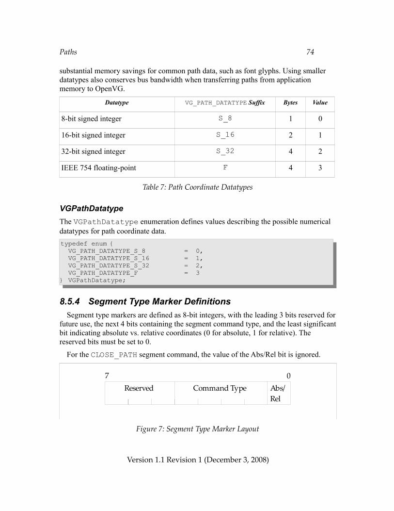
Paths 74
substantial memory savings for common path data, such as font glyphs. Using smaller datatypes also conserves bus bandwidth when transferring paths from application memory to OpenVG.
Datatype VG_PATH_DATATYPE Suffix Bytes Value
8-bit signed integer S_8 1 0
16-bit signed integer S_16 2 1
32-bit signed integer S_32 4 2
IEEE 754 floating-point F 4 3
Table 7: Path Coordinate Datatypes
VGPathDatatypeThe VGPathDatatype enumeration defines values describing the possible numerical datatypes for path coordinate data.typedef enum { VG_PATH_DATATYPE_S_8 = 0, VG_PATH_DATATYPE_S_16 = 1, VG_PATH_DATATYPE_S_32 = 2, VG_PATH_DATATYPE_F = 3} VGPathDatatype;
8.5.4 Segment Type Marker DefinitionsSegment type markers are defined as 8-bit integers, with the leading 3 bits reserved for
future use, the next 4 bits containing the segment command type, and the least significant bit indicating absolute vs. relative coordinates (0 for absolute, 1 for relative). The reserved bits must be set to 0.
For the CLOSE_PATH segment command, the value of the Abs/Rel bit is ignored.
Figure 7: Segment Type Marker Layout
Version 1.1 Revision 1 (December 3, 2008)
Abs/Rel
7 0Command TypeReserved
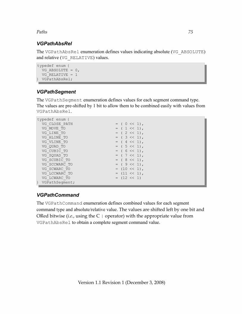
Paths 75
VGPathAbsRelThe VGPathAbsRel enumeration defines values indicating absolute (VG_ABSOLUTE) and relative (VG_RELATIVE) values.typedef enum { VG_ABSOLUTE = 0, VG_RELATIVE = 1} VGPathAbsRel;
VGPathSegmentThe VGPathSegment enumeration defines values for each segment command type. The values are pre-shifted by 1 bit to allow them to be combined easily with values from VGPathAbsRel.typedef enum { VG_CLOSE_PATH = ( 0 << 1), VG_MOVE_TO = ( 1 << 1), VG_LINE_TO = ( 2 << 1), VG_HLINE_TO = ( 3 << 1), VG_VLINE_TO = ( 4 << 1), VG_QUAD_TO = ( 5 << 1), VG_CUBIC_TO = ( 6 << 1), VG_SQUAD_TO = ( 7 << 1), VG_SCUBIC_TO = ( 8 << 1), VG_SCCWARC_TO = ( 9 << 1), VG_SCWARC_TO = (10 << 1), VG_LCCWARC_TO = (11 << 1), VG_LCWARC_TO = (12 << 1)} VGPathSegment;
VGPathCommandThe VGPathCommand enumeration defines combined values for each segment command type and absolute/relative value. The values are shifted left by one bit and ORed bitwise (i.e., using the C | operator) with the appropriate value from VGPathAbsRel to obtain a complete segment command value.
Version 1.1 Revision 1 (December 3, 2008)
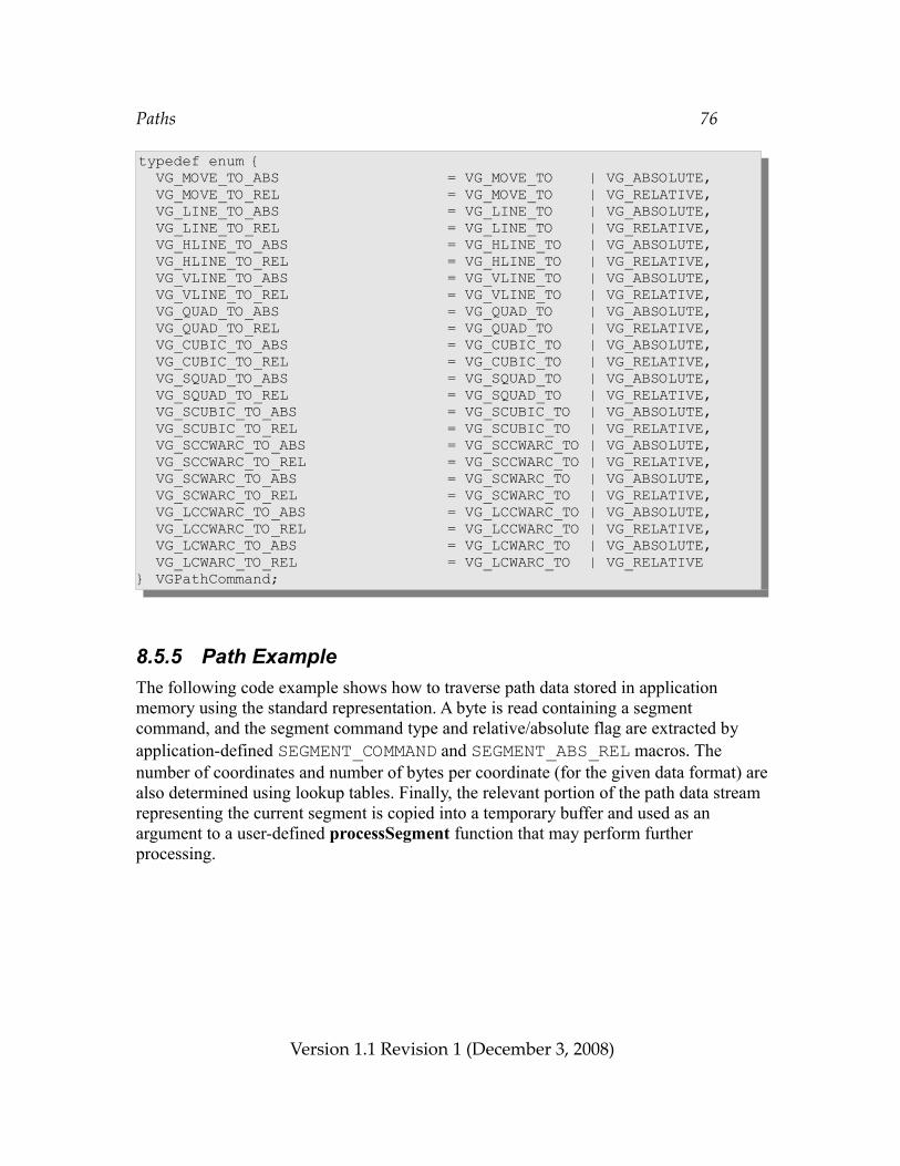
Paths 76
typedef enum { VG_MOVE_TO_ABS = VG_MOVE_TO | VG_ABSOLUTE, VG_MOVE_TO_REL = VG_MOVE_TO | VG_RELATIVE, VG_LINE_TO_ABS = VG_LINE_TO | VG_ABSOLUTE, VG_LINE_TO_REL = VG_LINE_TO | VG_RELATIVE, VG_HLINE_TO_ABS = VG_HLINE_TO | VG_ABSOLUTE, VG_HLINE_TO_REL = VG_HLINE_TO | VG_RELATIVE, VG_VLINE_TO_ABS = VG_VLINE_TO | VG_ABSOLUTE, VG_VLINE_TO_REL = VG_VLINE_TO | VG_RELATIVE, VG_QUAD_TO_ABS = VG_QUAD_TO | VG_ABSOLUTE, VG_QUAD_TO_REL = VG_QUAD_TO | VG_RELATIVE, VG_CUBIC_TO_ABS = VG_CUBIC_TO | VG_ABSOLUTE, VG_CUBIC_TO_REL = VG_CUBIC_TO | VG_RELATIVE, VG_SQUAD_TO_ABS = VG_SQUAD_TO | VG_ABSOLUTE, VG_SQUAD_TO_REL = VG_SQUAD_TO | VG_RELATIVE, VG_SCUBIC_TO_ABS = VG_SCUBIC_TO | VG_ABSOLUTE, VG_SCUBIC_TO_REL = VG_SCUBIC_TO | VG_RELATIVE, VG_SCCWARC_TO_ABS = VG_SCCWARC_TO | VG_ABSOLUTE, VG_SCCWARC_TO_REL = VG_SCCWARC_TO | VG_RELATIVE, VG_SCWARC_TO_ABS = VG_SCWARC_TO | VG_ABSOLUTE, VG_SCWARC_TO_REL = VG_SCWARC_TO | VG_RELATIVE, VG_LCCWARC_TO_ABS = VG_LCCWARC_TO | VG_ABSOLUTE, VG_LCCWARC_TO_REL = VG_LCCWARC_TO | VG_RELATIVE, VG_LCWARC_TO_ABS = VG_LCWARC_TO | VG_ABSOLUTE, VG_LCWARC_TO_REL = VG_LCWARC_TO | VG_RELATIVE} VGPathCommand;
8.5.5 Path ExampleThe following code example shows how to traverse path data stored in application memory using the standard representation. A byte is read containing a segment command, and the segment command type and relative/absolute flag are extracted by application-defined SEGMENT_COMMAND and SEGMENT_ABS_REL macros. The number of coordinates and number of bytes per coordinate (for the given data format) are also determined using lookup tables. Finally, the relevant portion of the path data stream representing the current segment is copied into a temporary buffer and used as an argument to a user-defined processSegment function that may perform further processing.
Version 1.1 Revision 1 (December 3, 2008)
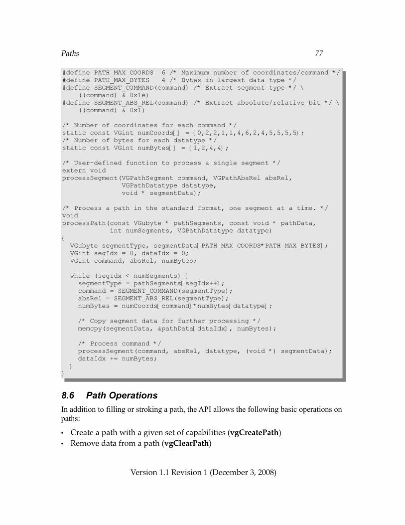
Paths 77
#define PATH_MAX_COORDS 6 /* Maximum number of coordinates/command */#define PATH_MAX_BYTES 4 /* Bytes in largest data type */#define SEGMENT_COMMAND(command) /* Extract segment type */ \ ((command) & 0x1e)#define SEGMENT_ABS_REL(command) /* Extract absolute/relative bit */ \ ((command) & 0x1)
/* Number of coordinates for each command */static const VGint numCoords[] = {0,2,2,1,1,4,6,2,4,5,5,5,5};/* Number of bytes for each datatype */static const VGint numBytes[] = {1,2,4,4};
/* User-defined function to process a single segment */extern voidprocessSegment(VGPathSegment command, VGPathAbsRel absRel, VGPathDatatype datatype, void * segmentData);
/* Process a path in the standard format, one segment at a time. */voidprocessPath(const VGubyte * pathSegments, const void * pathData, int numSegments, VGPathDatatype datatype){ VGubyte segmentType, segmentData[PATH_MAX_COORDS*PATH_MAX_BYTES]; VGint segIdx = 0, dataIdx = 0; VGint command, absRel, numBytes;
while (segIdx < numSegments) { segmentType = pathSegments[segIdx++]; command = SEGMENT_COMMAND(segmentType); absRel = SEGMENT_ABS_REL(segmentType); numBytes = numCoords[command]*numBytes[datatype];
/* Copy segment data for further processing */ memcpy(segmentData, &pathData[dataIdx], numBytes);
/* Process command */ processSegment(command, absRel, datatype, (void *) segmentData); dataIdx += numBytes; }}
8.6 Path OperationsIn addition to filling or stroking a path, the API allows the following basic operations on paths:
• Create a path with a given set of capabilities (vgCreatePath)• Remove data from a path (vgClearPath)
Version 1.1 Revision 1 (December 3, 2008)
Paths 78
• Deallocate a path (vgDestroyPath)• Query path information (using vgGetParameter)• Query the set of capabilities for a path (vgGetPathCapabilities)• Reduce the set of capabilities for a path (vgRemovePathCapabilities)• Append data from one path onto another (vgAppendPath)• Append data onto a path (vgAppendPathData)• Modify coordinates stored in a path (vgModifyPathCoords)• Transform a path (vgTransformPath)• Interpolate between two paths (vgInterpolatePath)• Determine the geometrical length of a path (vgPathLength)• Get position and tangent information for a point at a given geometric distance
along path (vgPointAlongPath)• Get an axis-aligned bounding box for a path (vgPathBounds,
vgTransformedPathBounds)
Higher-level geometric primitives are defined in the optional VGU utility library (see Section 17):
• Append a line to a path (vguLine)• Append a polyline (connected sequence of line segments) or polygon to a
path (vguPolygon)• Append a rectangle to a path (vguRect)• Append a round-cornered rectangle to a path (vguRoundRect)• Append an ellipse to a path (vguEllipse)• Append a circular arc to a path (vguArc)
8.6.1 Storage of PathsOpenVG stores path data internally to the implementation. Paths are referenced via opaque VGPath handles. Applications may initialize paths using the memory representation defined above or other representations defined by extensions.
It is possible for an implementation to store path data in hardware-accelerated memory. Implementations may also make use of their own internal representation of path segments. The intent is for applications to be able to define a set of paths, for example one for each glyph in the current typeface, and to be able to re-render each previously defined path with maximum efficiency.
Version 1.1 Revision 1 (December 3, 2008)
Paths 79
VGPathVGPath represents an opaque handle to a path.typedef VGHandle VGPath;
8.6.2 Creating and Destroying PathsPaths are created and destroyed using the vgCreatePath and vgDestroyPath functions. During the lifetime of a path, an application may indicate which path operations it plans to perform using path capability flags defined by the VGPathCapabilities enumeration.
VGPathCapabilitiesThe VGPathCapabilities enumeration defines a set of constants specifying which operations may be performed on a given path object. At the time a path is defined, the application specifies which operations it wishes to be able to perform on the path. Over time, the application may disable previously enabled capabilities, but it may not re-enable capabilities once they have been disabled. This feature allows OpenVG implementations to make use of internal path representations that may not support all path operations, possibly resulting in higher performance on paths where those operations will not be performed.
The capability bits and the functionality they allow are described below:• VG_PATH_CAPABILITY_APPEND_FROM – use path as the srcPath argument to
vgAppendPath• VG_PATH_CAPABILITY_APPEND_TO – use path as the dstPath argument to
vgAppendPath and vgAppendPathData• VG_PATH_CAPABILITY_MODIFY – use path as the dstPath argument to
vgModifyPathCoords• VG_PATH_CAPABILITY_TRANSFORM_FROM – use path as the srcPath argument to
vgTransformPath• VG_PATH_CAPABILITY_TRANSFORM_TO – use path as the dstPath argument to
vgTransformPath• VG_PATH_CAPABILITY_INTERPOLATE_FROM – use path as the startPath or endPath
argument to vgInterpolatePath• VG_PATH_CAPABILITY_INTERPOLATE_TO – use path as the dstPath argument to
vgInterpolatePath• VG_PATH_CAPABILITY_PATH_LENGTH – use path as the path argument to vgPathLength• VG_PATH_CAPABILITY_POINT_ALONG_PATH – use path as the path argument to
vgPointAlongPath• VG_PATH_CAPABILITY_TANGENT_ALONG_PATH – use path as the path argument to
vgPointAlongPath with non-NULL tangentX and tangentY arguments
Version 1.1 Revision 1 (December 3, 2008)
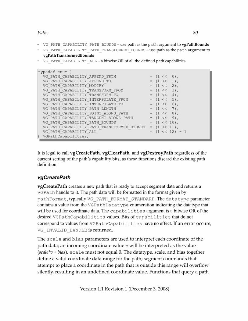
Paths 80
• VG_PATH_CAPABILITY_PATH_BOUNDS – use path as the path argument to vgPathBounds• VG_PATH_CAPABILITY_PATH_TRANSFORMED_BOUNDS – use path as the path argument to
vgPathTransformedBounds• VG_PATH_CAPABILITY_ALL – a bitwise OR of all the defined path capabilities
typedef enum { VG_PATH_CAPABILITY_APPEND_FROM = (1 << 0), VG_PATH_CAPABILITY_APPEND_TO = (1 << 1), VG_PATH_CAPABILITY_MODIFY = (1 << 2), VG_PATH_CAPABILITY_TRANSFORM_FROM = (1 << 3), VG_PATH_CAPABILITY_TRANSFORM_TO = (1 << 4), VG_PATH_CAPABILITY_INTERPOLATE_FROM = (1 << 5), VG_PATH_CAPABILITY_INTERPOLATE_TO = (1 << 6), VG_PATH_CAPABILITY_PATH_LENGTH = (1 << 7), VG_PATH_CAPABILITY_POINT_ALONG_PATH = (1 << 8), VG_PATH_CAPABILITY_TANGENT_ALONG_PATH = (1 << 9), VG_PATH_CAPABILITY_PATH_BOUNDS = (1 << 10), VG_PATH_CAPABILITY_PATH_TRANSFORMED_BOUNDS = (1 << 11), VG_PATH_CAPABILITY_ALL = (1 << 12) - 1} VGPathCapabilities;
It is legal to call vgCreatePath, vgClearPath, and vgDestroyPath regardless of the current setting of the path’s capability bits, as these functions discard the existing path definition.
vgCreatePathvgCreatePath creates a new path that is ready to accept segment data and returns a VGPath handle to it. The path data will be formatted in the format given by pathFormat, typically VG_PATH_FORMAT_STANDARD. The datatype parameter contains a value from the VGPathDatatype enumeration indicating the datatype that will be used for coordinate data. The capabilities argument is a bitwise OR of the desired VGPathCapabilities values. Bits of capabilities that do not correspond to values from VGPathCapabilities have no effect. If an error occurs, VG_INVALID_HANDLE is returned.
The scale and bias parameters are used to interpret each coordinate of the path data; an incoming coordinate value v will be interpreted as the value (scale*v + bias). scale must not equal 0. The datatype, scale, and bias together define a valid coordinate data range for the path; segment commands that attempt to place a coordinate in the path that is outside this range will overflow silently, resulting in an undefined coordinate value. Functions that query a path
Version 1.1 Revision 1 (December 3, 2008)
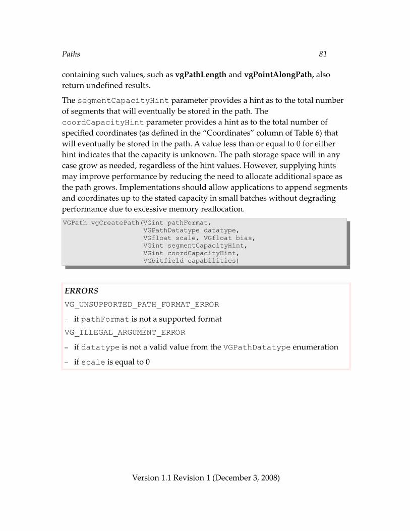
Paths 81
containing such values, such as vgPathLength and vgPointAlongPath, also return undefined results.
The segmentCapacityHint parameter provides a hint as to the total number of segments that will eventually be stored in the path. The coordCapacityHint parameter provides a hint as to the total number of specified coordinates (as defined in the “Coordinates” column of Table 6) that will eventually be stored in the path. A value less than or equal to 0 for either hint indicates that the capacity is unknown. The path storage space will in any case grow as needed, regardless of the hint values. However, supplying hints may improve performance by reducing the need to allocate additional space as the path grows. Implementations should allow applications to append segments and coordinates up to the stated capacity in small batches without degrading performance due to excessive memory reallocation.VGPath vgCreatePath(VGint pathFormat, VGPathDatatype datatype, VGfloat scale, VGfloat bias, VGint segmentCapacityHint, VGint coordCapacityHint, VGbitfield capabilities)
ERRORSVG_UNSUPPORTED_PATH_FORMAT_ERROR– if pathFormat is not a supported formatVG_ILLEGAL_ARGUMENT_ERROR– if datatype is not a valid value from the VGPathDatatype enumeration
– if scale is equal to 0
Version 1.1 Revision 1 (December 3, 2008)
Paths 82
vgClearPathvgClearPath removes all segment command and coordinate data associated with a path. The handle continues to be valid for use in the future, and the path format and datatype retain their existing values. The capabilities argument is a bitwise OR of the desired VGPathCapabilities values. Bits of capabilities that do not correspond to values from VGPathCapabilities have no effect. Using vgClearPath may be more efficient than destroying and re-creating a path for short-lived paths.void vgClearPath(VGPath path, VGbitfield capabilities)
ERRORSVG_BAD_HANDLE_ERROR– if path is not a valid path handle, or is not shared with the current context
vgDestroyPathvgDestroyPath releases any resources associated with path, and makes the handle invalid in all contexts that shared it.void vgDestroyPath(VGPath path)
ERRORSVG_BAD_HANDLE_ERROR– if path is not a valid path handle, or is not shared with the current context
8.6.3 Path Queries
VGPathParamTypeValues from the VGPathParamType enumeration may be used as the paramType argument to vgGetParameter to query various features of a path. All of the parameters defined by VGPathParamType are read-only. Table 8 shows the datatypes for each parameter type.
Version 1.1 Revision 1 (December 3, 2008)
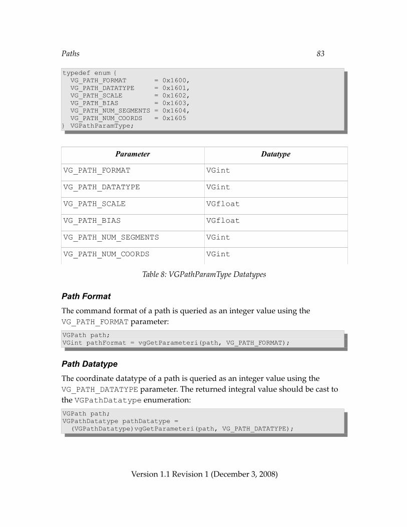
Paths 83
typedef enum { VG_PATH_FORMAT = 0x1600, VG_PATH_DATATYPE = 0x1601, VG_PATH_SCALE = 0x1602, VG_PATH_BIAS = 0x1603, VG_PATH_NUM_SEGMENTS = 0x1604, VG_PATH_NUM_COORDS = 0x1605} VGPathParamType;
Parameter Datatype
VG_PATH_FORMAT VGintVG_PATH_DATATYPE VGintVG_PATH_SCALE VGfloatVG_PATH_BIAS VGfloatVG_PATH_NUM_SEGMENTS VGintVG_PATH_NUM_COORDS VGint
Table 8: VGPathParamType Datatypes
Path FormatThe command format of a path is queried as an integer value using the VG_PATH_FORMAT parameter:VGPath path;VGint pathFormat = vgGetParameteri(path, VG_PATH_FORMAT);
Path DatatypeThe coordinate datatype of a path is queried as an integer value using the VG_PATH_DATATYPE parameter. The returned integral value should be cast to the VGPathDatatype enumeration:VGPath path;VGPathDatatype pathDatatype = (VGPathDatatype)vgGetParameteri(path, VG_PATH_DATATYPE);
Version 1.1 Revision 1 (December 3, 2008)
Paths 84
Path ScaleThe scale factor of the path is queried as a floating-point value using the VG_PATH_SCALE parameter:VGPath path;VGfloat pathScale = vgGetParameterf(path, VG_PATH_SCALE);
Path BiasThe bias of the path is queried as a floating-point value using the VG_PATH_BIAS parameter:VGPath path;VGfloat pathBias = vgGetParameterf(path, VG_PATH_BIAS);
Number of SegmentsThe number of segments stored in the path is queried as an integer value using the VG_PATH_NUM_SEGMENTS parameter:VGPath path;VGint pathNumSegments = vgGetParameteri(path, VG_PATH_NUM_SEGMENTS);
Number of CoordinatesThe total number of specified coordinates (i.e., those defined in the “Coordinates” column of Table 6) stored in the path is queried as an integer value using the VG_PATH_NUM_COORDS parameter:VGPath path;VGint pathNumCoords = vgGetParameteri(path, VG_PATH_NUM_COORDS);
8.6.4 Querying and Modifying Path Capabilities
vgGetPathCapabilitiesThe vgGetPathCapabilities function returns the current capabilities of the path, as a bitwise OR of VGPathCapabilities constants. If an error occurs, 0 is returned.VGbitfield vgGetPathCapabilities(VGPath path)
Version 1.1 Revision 1 (December 3, 2008)
Paths 85
ERRORSVG_BAD_HANDLE_ERROR– if path is not a valid path handle, or is not shared with the current context
vgRemovePathCapabilitiesThe vgRemovePathCapabilities function requests the set of capabilities specified in the capabilities argument to be disabled for the given path. The capabilities argument is a bitwise OR of the VGPathCapabilities values whose removal is requested. Attempting to remove a capability that is already disabled has no effect. Bits of capabilities that do not correspond to values from VGPathCapabilities have no effect.
An implementation may choose to ignore the request to remove a particular capability if no significant performance improvement would result. In this case, vgGetPathCapabilities will continue to report the capability as enabled.
void vgRemovePathCapabilities(VGPath path, VGbitfield capabilities)
ERRORSVG_BAD_HANDLE_ERROR– if path is not a valid path handle, or is not shared with the current context
8.6.5 Copying Data Between Paths
vgAppendPathvgAppendPath appends a copy of all path segments from srcPath onto the end of the existing data in dstPath. It is legal for srcPath and dstPath to be handles to the same path object, in which case the contents of the path are duplicated. If srcPath and dstPath are handles to distinct path objects, the contents of srcPath will not be affected by the call.
The VG_PATH_CAPABILITY_APPEND_FROM capability must be enabled for srcPath, and the VG_PATH_CAPABILITY_APPEND_TO capability must be enabled for dstPath.
Version 1.1 Revision 1 (December 3, 2008)
Paths 86
If the scale and bias of dstPath define a narrower range than that of srcPath, overflow may occur silently.void vgAppendPath(VGPath dstPath, VGPath srcPath)
ERRORSVG_BAD_HANDLE_ERROR– if either dstPath or srcPath is not a valid path handle, or is not shared
with the current contextVG_PATH_CAPABILITY_ERROR– if VG_PATH_CAPABILITY_APPEND_FROM is not enabled for srcPath
– if VG_PATH_CAPABILITY_APPEND_TO is not enabled for dstPath
8.6.6 Appending Data to a Path
vgAppendPathDatavgAppendPathData appends data taken from pathData to the given path dstPath. The data are formatted using the path format of dstPath (as returned by querying the path’s VG_PATH_FORMAT parameter using vgGetParameteri). The numSegments parameter gives the total number of entries in the pathSegments array, and must be greater than 0. Legal values for the pathSegments array are the values from the VGPathCommand enumeration as well as VG_CLOSE_PATH and (VG_CLOSE_PATH | VG_RELATIVE) (which are synonymous).
The pathData pointer must be aligned on a 1-, 2-, or 4-byte boundary (as defined in the “Bytes” column of Table 7) depending on the size of the coordinate datatype (as returned by querying the path’s VG_PATH_DATATYPE parameter using vgGetParameteri). The VG_PATH_CAPABILITY_APPEND_TO capability must be enabled for path.
Each incoming coordinate value, regardless of datatype, is transformed by the scale factor and bias of the path.void vgAppendPathData(VGPath dstPath, VGint numSegments, const VGubyte * pathSegments, const void * pathData)
Version 1.1 Revision 1 (December 3, 2008)
Paths 87
ERRORSVG_BAD_HANDLE_ERROR– if dstPath is not a valid path handle, or is not shared with the current
contextVG_PATH_CAPABILITY_ERROR– if VG_PATH_CAPABILITY_APPEND_TO is not enabled for dstPathVG_ILLEGAL_ARGUMENT_ERROR– if pathSegments or pathData is NULL– if pathData is not properly aligned
– if numSegments is less than or equal to 0
– if pathSegments contains an illegal command
8.6.7 Modifying Path DataCoordinate data in an existing path may be modified, for example to create animation effects. Implementations should choose an internal representation for paths that have the VG_PATH_CAPABILITY_MODIFY capability enabled that allows for efficient modification of the coordinate data.
vgModifyPathCoordsvgModifyPathCoords modifies the coordinate data for a contiguous range of segments of dstPath, starting at startIndex (where 0 is the index of the first path segment) and having length numSegments. The data in pathData must be formatted in exactly the same manner as the original coordinate data for the given segment range, unless the path has been transformed using vgTransformPath or interpolated using vgInterpolatePath. In these cases, the path will have been subject to the segment promotion rules specified in those functions.
The pathData pointer must be aligned on a 1-, 2-, or 4-byte boundary depending on the size of the coordinate datatype (as returned by querying the path’s VG_PATH_DATATYPE parameter using vgGetParameteri). The VG_PATH_CAPABILITY_MODIFY capability must be enabled for path.
Version 1.1 Revision 1 (December 3, 2008)
Paths 88
Each incoming coordinate value, regardless of datatype, is transformed by the scale factor and bias of the path.void vgModifyPathCoords(VGPath dstPath, VGint startIndex, VGint numSegments, const void * pathData)
ERRORSVG_BAD_HANDLE_ERROR– if dstPath is not a valid path handle, or is not shared with the current
contextVG_PATH_CAPABILITY_ERROR– if VG_PATH_CAPABILITY_MODIFY is not enabled for dstPathVG_ILLEGAL_ARGUMENT_ERROR– if pathData is NULL– if pathData is not properly aligned
– if startIndex is less than 0
– if numSegments is less than or equal to 0
– if startIndex + numSegments is greater than the number of segments in the path
8.6.8 Transforming a Path
vgTransformPathvgTransformPath appends a transformed copy of srcPath to the current contents of dstPath. The appended path is equivalent to the results of applying the current path-user-to-surface transformation (VG_MATRIX_PATH_USER_TO_SURFACE) to srcPath.
It is legal for srcPath and dstPath to be handles to the same path object, in which case the transformed path will be appended to the existing path. If srcPath and dstPath are handles to distinct path objects, the contents of srcPath will not be affected by the call.
Version 1.1 Revision 1 (December 3, 2008)
Paths 89
All HLINE_TO_* and VLINE_TO_* segments present in srcPath are implicitly converted to LINE_TO_* segments prior to applying the transformation. The original copies of these segments in srcPath remain unchanged.
Any *ARC_TO segments are transformed, but the endpoint parametrization of the resulting arc segments are implementation-dependent. The results of calling vgInterpolatePath on a transformed path that contains such segments are undefined.
The VG_PATH_CAPABILITY_TRANSFORM_FROM capability must be enabled for srcPath, and the VG_PATH_CAPABILITY_TRANSFORM_TO capability must be enabled for dstPath.
Overflow may occur silently if coordinates are transformed outside the datatype range of dstPath.void vgTransformPath(VGPath dstPath, VGPath srcPath)
ERRORSVG_BAD_HANDLE_ERROR– if either dstPath or srcPath is not a valid path handle, or is not shared with
the current contextVG_PATH_CAPABILITY_ERROR– if VG_PATH_CAPABILITY_TRANSFORM_FROM is not enabled for srcPath
– if VG_PATH_CAPABILITY_TRANSFORM_TO is not enabled for dstPath
8.6.9 Interpolating Between PathsInterpolation takes two compatible paths, in a sense described below, and defines a new path that interpolates between them by a parameter amount. When amount is equal to 0, the result is equivalent to the first path; when amount is equal to 1, the result is equivalent to the second path. Values between 0 and 1 produce paths that smoothly interpolate between the two extremes. Values outside the [0, 1] range produce extrapolated paths. Conceptually, interpolation occurs as follows. First, the two path parameters are copied and the copies are normalized by:• Converting all coordinates to floating-point format, applying the path scale and bias
parameters• Converting all relative segments to absolute form• Converting {H,V}LINE_TO_* segments to LINE_TO form
Version 1.1 Revision 1 (December 3, 2008)
Paths 90
• Converting (S)QUAD_TO_*/SCUBIC_TO_* segments to CUBIC_TO form• Retaining all *ARC_TO_* and CLOSE_PATH segmentsIf, following normalization, both paths have the same sequence of segment types (treating all forms of arc as the same), interpolation proceeds by linearly interpolating between each corresponding pair of segment parameters in the normalized paths. If the starting arc type differs from the final arc type, the starting arc type is used for values of amount less than 0.5, and the final arc type is used for values greater than or equal to 0.5. Finally, the coordinates are converted to the data type of the destination.
vgInterpolatePathThe vgInterpolatePath function appends a path, defined by interpolation (or extrapolation) between the paths startPath and endPath by the given amount, to the path dstPath. It returns VG_TRUE if interpolation was successful (i.e., the paths had compatible segment types after normalization), and VG_FALSE otherwise. If interpolation is unsuccessful, dstPath is left unchanged.
It is legal for dstPath to be a handle to the same path object as either startPath or endPath or both, in which case the contents of the source path or paths referenced by dstPath will have the interpolated path appended. If dstPath is not the a handle to the same path object as either startPath or endPath, the contents of startPath and endPath will not be affected by the call.
Overflow may occur silently if the datatype of dstPath has insufficient range to store an interpolated coordinate value.
The VG_PATH_CAPABILITY_INTERPOLATE_FROM capability must be enabled for both of startPath and endPath, and the INTERPOLATE_TO capability must be enabled for dstPath.VGboolean vgInterpolatePath(VGPath dstPath, VGPath startPath, VGPath endPath, VGfloat amount)
Version 1.1 Revision 1 (December 3, 2008)
Paths 91
ERRORSVG_BAD_HANDLE_ERROR– if any of dstPath, startPath, or endPath is not a valid path handle, or is
not shared with the current contextVG_PATH_CAPABILITY_ERROR– if VG_PATH_CAPABILITY_PATH_INTERPOLATE_TO is not enabled for dstPath
– if VG_PATH_CAPABILITY_PATH_INTERPOLATE_FROM is not enabled for startPath or endPath
8.6.10 Length of a PathAn approximation to the geometric length of a portion of a path may be obtained by calling the vgPathLength function. MOVE_TO segments and implicit path closures (see Section 8.7.1) do not contribute to the path length. CLOSE_PATH segments have the same length as a LINE_TO segment with the same endpoints.
vgPathLengthThe vgPathLength function returns the length of a given portion of a path in the user coordinate system (that is, in the path’s own coordinate system, disregarding any matrix settings). Only the subpath consisting of the numSegments path segments beginning with startSegment (where the initial path segment has index 0) is used. If an error occurs, -1.0f is returned.
The VG_PATH_CAPABILITY_PATH_LENGTH capability must be enabled for path.VGfloat vgPathLength(VGPath path, VGint startSegment, VGint numSegments);
Version 1.1 Revision 1 (December 3, 2008)
Paths 92
ERRORSVG_BAD_HANDLE_ERROR– if path is not a valid path handle, or is not shared with the current contextVG_PATH_CAPABILITY_ERROR– if VG_PATH_CAPABILITY_PATH_LENGTH is not enabled for pathVG_ILLEGAL_ARGUMENT_ERROR– if startSegment is less than 0 or greater than the index of the final path
segment
– if numSegments is less than or equal to 0
– if (startSegment + numSegments – 1) is greater than the index of the final path segment
8.6.11 Position and Tangent Along a PathSome path operations, such as the placement and orientation of text along a path, require the computation of a set of points along a path as well as a normal (perpendicular) vector at each point. The vgPointAlongPath function provides points along the path as well as normalized tangent vectors (from which normals may easily be derived).
The Tangents of a Path SegmentThe tangent at a given point along a path is defined as a vector pointing in the same direction as the path at that point. The tangent at any point of a line segment is parallel to the line segment; the tangent at any point along a Bézier curve or elliptical arc segment may be defined using the derivatives of the parametric equations x(t) and y(t) that define the curve. The incoming tangent at a point is defined using the direction in which the curve is “traveling” prior to arriving at the point; the outgoing tangent is defined using the direction the curve is traveling as it leaves the point. The incoming and outgoing tangents may differ at a vertex joining different curve segments, or at a sharp “cusp” in a curve.
If a point along a path segment has no tangent defined, for example where a path segment has collapsed to a single point, the following algorithm is used to define incoming and outgoing tangents at the point. Search backwards until a segment is found with a tangent defined at its end point, or the start of the current path is reached; if a tangent is found, use it as the incoming tangent. Search forwards until a segment is found with a tangent defined at its starting point, or the end of the current path is reached; if a
Version 1.1 Revision 1 (December 3, 2008)
Paths 93
tangent is found, use it as the outgoing tangent. If these searches produce exactly one defined tangent, that tangent is used as both the incoming and outgoing tangent. If the searches produced no defined tangent, the incoming and outgoing tangents are both assigned the value (1, 0). Tangent vectors are normalized to have unit length.
vgPointAlongPathThe vgPointAlongPath function returns the point lying a given distance along a given portion of a path and the unit-length tangent vector at that point. Only the subpath consisting of the numSegments path segments beginning with startSegment (where the initial path segment has index 0) is used. For the remainder of this section we refer only to this subpath when discussing paths.
If distance is less than or equal to 0, the starting point of the path is used. If distance is greater than or equal to the path length (i.e., the value returned by vgPathLength when called with the same startSegment and numSegments parameters), the visual ending point of the path is used.
Intermediate values return the (x, y) coordinates and tangent vector of the point at the given distance along the path. Because it is not possible in general to compute exact distances along a path, an implementation is not required to use exact computation even for segments where such computation would be possible. For example, the path:MOVE_TO 0, 0; LINE_TO 10, 0 // draw a line of length 10MOVE_TO 10, 10 // create a discontinuityLINE_TO 10, 20 // draw a line of length 10may return either (10, 0) or (10, 10) (or points nearby) as the point at distance 10.0. Implementations are not required to compute distances exactly, as long as they satisfy the constraint that as distance increases monotonically the returned point and tangent move forward monotonically along the path.
Where the implementation is able to determine that the point being queried lies exactly at a discontinuity or cusp, the incoming point and tangent should be returned. In the example above, returning the pre-discontinuity point (10, 0) and incoming tangent (1, 0) is preferred to returning the post-discontinuity point (10, 10) and outgoing tangent (0, 1).
The VG_PATH_CAPABILITY_POINT_ALONG_PATH capability must be enabled for path.
If the reference arguments x and y are both non-NULL, and the
Version 1.1 Revision 1 (December 3, 2008)
Paths 94
VG_PATH_CAPABILITY_POINT_ALONG_PATH capability is enabled for path, the point (x, y) is returned in x and y. Otherwise the variables referenced by x and y are not written.
If the reference arguments tangentX and tangentY are both non-NULL, and the VG_PATH_CAPABILITY_TANGENT_ALONG_PATH capability is enabled for path, the geometric tangent vector at the point (x, y) is returned in tangentX and tangentY. Otherwise the variables referenced by tangentX and tangentY are not written.
Where the incoming tangent is defined, vgPointAlongPath returns it. Where only the outgoing tangent is defined, the outgoing tangent is returned.
The points returned by vgPointAlongPath are not guaranteed to match the path as rendered; some deviation is to be expected.
void vgPointAlongPath(VGPath path, VGint startSegment, VGint numSegments, VGfloat distance, VGfloat * x, VGfloat * y, VGfloat * tangentX, VGfloat * tangentY)
Version 1.1 Revision 1 (December 3, 2008)
Paths 95
ERRORSVG_BAD_HANDLE_ERROR– if path is not a valid path handle, or is not shared with the current contextVG_PATH_CAPABILITY_ERROR– If x and y are both non-NULL, and the VG_PATH_CAPABILITY_POINT_ALONG_PATH is not enabled for path
– If tangentX and tangentY are both non-NULL, and the VG_PATH_CAPABILITY_TANGENT_ALONG_PATH capability is not enabled for path
VG_ILLEGAL_ARGUMENT_ERROR– if startSegment is less than 0 or greater than the index of the final path
segment
– if numSegments is less than or equal to 0
– if (startSegment + numSegments – 1) is less than 0 or greater than the index of the final path segment
– if x, y, tangentX or tangentY is not properly aligned
8.6.12 Querying the Bounding Box of a PathTo draw complex scenes efficiently, it is important to avoid drawing objects that do not appear in the region being drawn. A simple way to determine whether an object may be visible is to determine whether its bounding box – an axis-aligned rectangle that is guaranteed to contain the entire object – intersects the drawn region. The vgPathBounds and vgPathTransformedBounds functions provide bounding box information.
Two types of bounding boxes may be obtained for a path. The first, obtained by calling vgPathBounds, returns a tight axis-aligned bounding box for the area contained within the path in its own coordinate system. The second, obtained by calling vgPathTransformedBounds, returns an axis-aligned bounding box for the path as it will appear when drawn on the drawing surface (i.e., following application of the current path-user-to-surface transform). The latter function does not guarantee to bound the shape tightly, but still may provide tighter bounds than those obtained by transforming the result of vgPathBounds, at a lower cost.
Version 1.1 Revision 1 (December 3, 2008)
Paths 96
The bounding box of a path is defined to contain all points along the path, including isolated points created by MOVE_TO segments. The fill rule has no effect on the determination of the bounding box. If the path is to be stroked, the application must adjust the bounding box to take the stroking parameters into account. Note that Miter joins in particular may extend far outside the bounding box.
vgPathBoundsThe vgPathBounds function returns an axis-aligned bounding box that tightly bounds the interior of the given path. Stroking parameters are ignored. If path is empty, minX and minY are set to 0 and width and height are set to -1. If path contains a single point, minX and minY are set to the coordinates of the point and width and height are set to 0.
The VG_PATH_CAPABILITY_PATH_BOUNDS capability must be enabled for path.void vgPathBounds(VGPath path, VGfloat * minX, VGfloat * minY, VGfloat * width, VGfloat * height)
ERRORSVG_BAD_HANDLE_ERROR– if path is not a valid path handle, or is not shared with the current contextVG_ILLEGAL_ARGUMENT_ERROR– if minX, minY, width, or height is NULL
– if minX, minY, width, or height is not properly alignedVG_PATH_CAPABILITY_ERROR– if VG_PATH_CAPABILITY_PATH_BOUNDS is not enabled for path
vgPathTransformedBoundsThe vgPathTransformedBounds function returns an axis-aligned bounding box that is guaranteed to enclose the geometry of the given path following transformation by the current path-user-to-surface transform. The returned bounding box is not guaranteed to fit tightly around the path geometry. If path is empty, minX and minY are set to 0 and width and height are set to -1. If
Version 1.1 Revision 1 (December 3, 2008)
Paths 97
path contains a single point, minX and minY are set to the transformed coordinates of the point and width and height are set to 0.
The VG_PATH_CAPABILITY_PATH_TRANSFORMED_BOUNDS capability must be enabled for path.void vgPathTransformedBounds(VGPath path, VGfloat * minX, VGfloat * minY, VGfloat * width, VGfloat * height)
ERRORSVG_BAD_HANDLE_ERROR– if path is not a valid path handle, or is not shared with the current contextVG_ILLEGAL_ARGUMENT_ERROR– if minX, minY, width, or height is NULL
– if minX, minY, width, or height is not properly alignedVG_PATH_CAPABILITY_ERROR– if VG_PATH_CAPABILITY_PATH_TRANSFORMED_BOUNDS is not enabled
for path
8.7 Interpretation of PathsThe interpretation of a path, composed of a sequence of one or more subpaths, depends on whether it is to be stroked or filled. For stroked paths, each subpath has stroking parameters applied to it separately, with the dash phase at the end of each subpath used at the beginning of the next subpath. This process results in a set of stroked shapes. The union of these shapes then defines the outline path to be filled. For filled paths, the interior of the path (as defined below) is filled.
8.7.1 Filling PathsA simple, non-self-intersecting closed path divides the plane into two regions, a bounded inside region and an unbounded outside region. Note that knowing the orientation of the outermost path (i.e., clockwise or counter-clockwise) is not necessary to differentiate between the inside and outside regions.
A path that self-intersects, or that has multiple overlapping subpaths, requires additional information in order to define the inside region. Two rules that provide different
Version 1.1 Revision 1 (December 3, 2008)
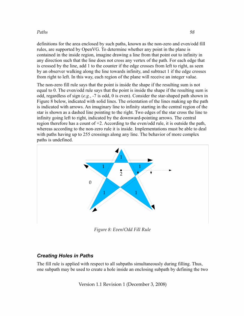
Paths 98
definitions for the area enclosed by such paths, known as the non-zero and even/odd fill rules, are supported by OpenVG. To determine whether any point in the plane is contained in the inside region, imagine drawing a line from that point out to infinity in any direction such that the line does not cross any vertex of the path. For each edge that is crossed by the line, add 1 to the counter if the edge crosses from left to right, as seen by an observer walking along the line towards infinity, and subtract 1 if the edge crosses from right to left. In this way, each region of the plane will receive an integer value.
The non-zero fill rule says that the point is inside the shape if the resulting sum is not equal to 0. The even/odd rule says that the point is inside the shape if the resulting sum is odd, regardless of sign (e.g., -7 is odd, 0 is even). Consider the star-shaped path shown in Figure 8 below, indicated with solid lines. The orientation of the lines making up the path is indicated with arrows. An imaginary line to infinity starting in the central region of the star is shown as a dashed line pointing to the right. Two edges of the star cross the line to infinity going left to right, indicated by the downward-pointing arrows. The central region therefore has a count of +2. According to the even/odd rule, it is outside the path, whereas according to the non-zero rule it is inside. Implementations must be able to deal with paths having up to 255 crossings along any line. The behavior of more complex paths is undefined.
Figure 8: Even/Odd Fill Rule
Creating Holes in PathsThe fill rule is applied with respect to all subpaths simultaneously during filling. Thus, one subpath may be used to create a hole inside an enclosing subpath by defining the two
Version 1.1 Revision 1 (December 3, 2008)
12
1
0
1
1 1
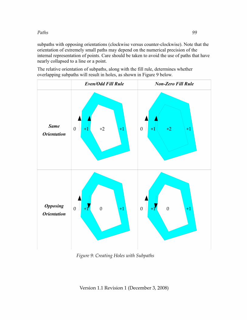
Paths 99
subpaths with opposing orientations (clockwise versus counter-clockwise). Note that the orientation of extremely small paths may depend on the numerical precision of the internal representation of points. Care should be taken to avoid the use of paths that have nearly collapsed to a line or a point.
The relative orientation of subpaths, along with the fill rule, determines whether overlapping subpaths will result in holes, as shown in Figure 9 below.
Even/Odd Fill Rule Non-Zero Fill Rule
SameOrientation
OpposingOrientation
Figure 9: Creating Holes with Subpaths
Version 1.1 Revision 1 (December 3, 2008)
0 +1 0 +10 +1 0 +1
0 +1 +2 +10 +1 +2 +1
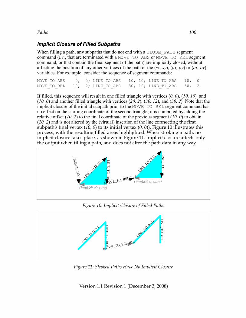
Paths 100
Implicit Closure of Filled SubpathsWhen filling a path, any subpaths that do not end with a CLOSE_PATH segment command (i.e., that are terminated with a MOVE_TO_ABS or MOVE_TO_REL segment command, or that contain the final segment of the path) are implicitly closed, without affecting the position of any other vertices of the path or the (sx, sy), (px, py) or (ox, oy) variables. For example, consider the sequence of segment commands:MOVE_TO_ABS 0, 0; LINE_TO_ABS 10, 10; LINE_TO_ABS 10, 0MOVE_TO_REL 10, 2; LINE_TO_ABS 30, 12; LINE_TO_ABS 30, 2
If filled, this sequence will result in one filled triangle with vertices (0, 0), (10, 10), and (10, 0) and another filled triangle with vertices (20, 2), (30, 12), and (30, 2). Note that the implicit closure of the initial subpath prior to the MOVE_TO_REL segment command has no effect on the starting coordinate of the second triangle; it is computed by adding the relative offset (10, 2) to the final coordinate of the previous segment (10, 0) to obtain (20, 2) and is not altered by the (virtual) insertion of the line connecting the first subpath’s final vertex (10, 0) to its initial vertex (0, 0)). Figure 10 illustrates this process, with the resulting filled areas highlighted. When stroking a path, no implicit closure takes place, as shown in Figure 11. Implicit closure affects only the output when filling a path, and does not alter the path data in any way.
Figure 10: Implicit Closure of Filled Paths
Figure 11: Stroked Paths Have No Implicit Closure
Version 1.1 Revision 1 (December 3, 2008)
MO
VE_TO
0,0 LINE_T0 10,10
LINE_TO
10,0
MOVE_TO_REL 10,2LIN
E_TO 30,12
LINE_TO
30,2
(implicit closure)(implicit closure)
LINE_TO 30,12
LINE_T0 10,10
LINE_TO
10,0
LINE_TO
30,2
MOVE_TO_REL 10,2
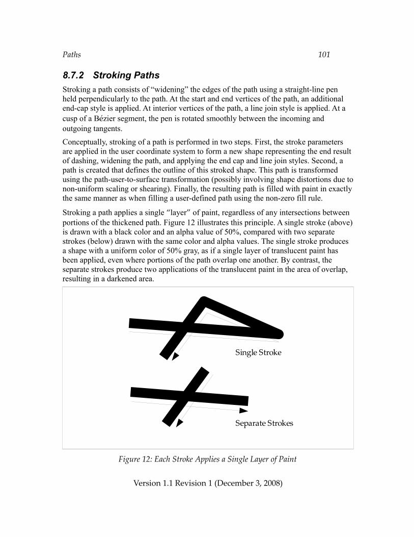
Paths 101
8.7.2 Stroking PathsStroking a path consists of “widening” the edges of the path using a straight-line pen held perpendicularly to the path. At the start and end vertices of the path, an additional end-cap style is applied. At interior vertices of the path, a line join style is applied. At a cusp of a Bézier segment, the pen is rotated smoothly between the incoming and outgoing tangents.
Conceptually, stroking of a path is performed in two steps. First, the stroke parameters are applied in the user coordinate system to form a new shape representing the end result of dashing, widening the path, and applying the end cap and line join styles. Second, a path is created that defines the outline of this stroked shape. This path is transformed using the path-user-to-surface transformation (possibly involving shape distortions due to non-uniform scaling or shearing). Finally, the resulting path is filled with paint in exactly the same manner as when filling a user-defined path using the non-zero fill rule.
Stroking a path applies a single “layer” of paint, regardless of any intersections between portions of the thickened path. Figure 12 illustrates this principle. A single stroke (above) is drawn with a black color and an alpha value of 50%, compared with two separate strokes (below) drawn with the same color and alpha values. The single stroke produces a shape with a uniform color of 50% gray, as if a single layer of translucent paint has been applied, even where portions of the path overlap one another. By contrast, the separate strokes produce two applications of the translucent paint in the area of overlap, resulting in a darkened area.
Figure 12: Each Stroke Applies a Single Layer of Paint
Version 1.1 Revision 1 (December 3, 2008)
Single Stroke
Separate Strokes
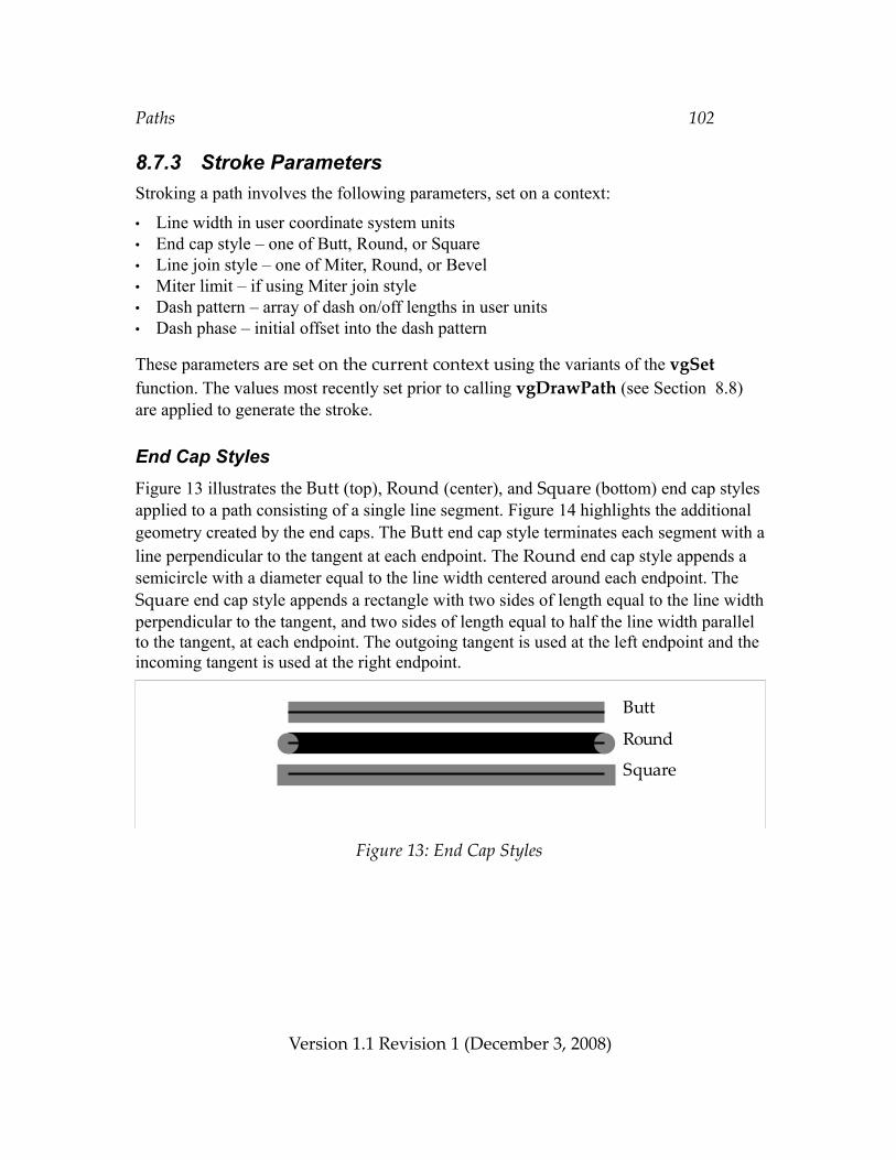
Paths 102
8.7.3 Stroke ParametersStroking a path involves the following parameters, set on a context:
• Line width in user coordinate system units• End cap style – one of Butt, Round, or Square• Line join style – one of Miter, Round, or Bevel• Miter limit – if using Miter join style• Dash pattern – array of dash on/off lengths in user units• Dash phase – initial offset into the dash pattern
These parameters are set on the current context using the variants of the vgSet function. The values most recently set prior to calling vgDrawPath (see Section 8.8) are applied to generate the stroke.
End Cap StylesFigure 13 illustrates the Butt (top), Round (center), and Square (bottom) end cap styles applied to a path consisting of a single line segment. Figure 14 highlights the additional geometry created by the end caps. The Butt end cap style terminates each segment with a line perpendicular to the tangent at each endpoint. The Round end cap style appends a semicircle with a diameter equal to the line width centered around each endpoint. The Square end cap style appends a rectangle with two sides of length equal to the line width perpendicular to the tangent, and two sides of length equal to half the line width parallel to the tangent, at each endpoint. The outgoing tangent is used at the left endpoint and the incoming tangent is used at the right endpoint.
Figure 13: End Cap Styles
Version 1.1 Revision 1 (December 3, 2008)
Butt
Round
Square
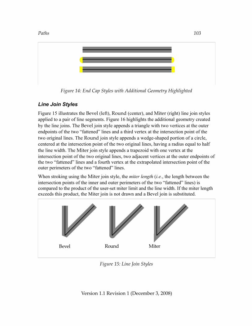
Paths 103
Figure 14: End Cap Styles with Additional Geometry Highlighted
Line Join StylesFigure 15 illustrates the Bevel (left), Round (center), and Miter (right) line join styles applied to a pair of line segments. Figure 16 highlights the additional geometry created by the line joins. The Bevel join style appends a triangle with two vertices at the outer endpoints of the two “fattened” lines and a third vertex at the intersection point of the two original lines. The Round join style appends a wedge-shaped portion of a circle, centered at the intersection point of the two original lines, having a radius equal to half the line width. The Miter join style appends a trapezoid with one vertex at the intersection point of the two original lines, two adjacent vertices at the outer endpoints of the two “fattened” lines and a fourth vertex at the extrapolated intersection point of the outer perimeters of the two “fattened” lines.
When stroking using the Miter join style, the miter length (i.e., the length between the intersection points of the inner and outer perimeters of the two “fattened” lines) is compared to the product of the user-set miter limit and the line width. If the miter length exceeds this product, the Miter join is not drawn and a Bevel join is substituted.
Figure 15: Line Join Styles
Version 1.1 Revision 1 (December 3, 2008)
Bevel Round Miter
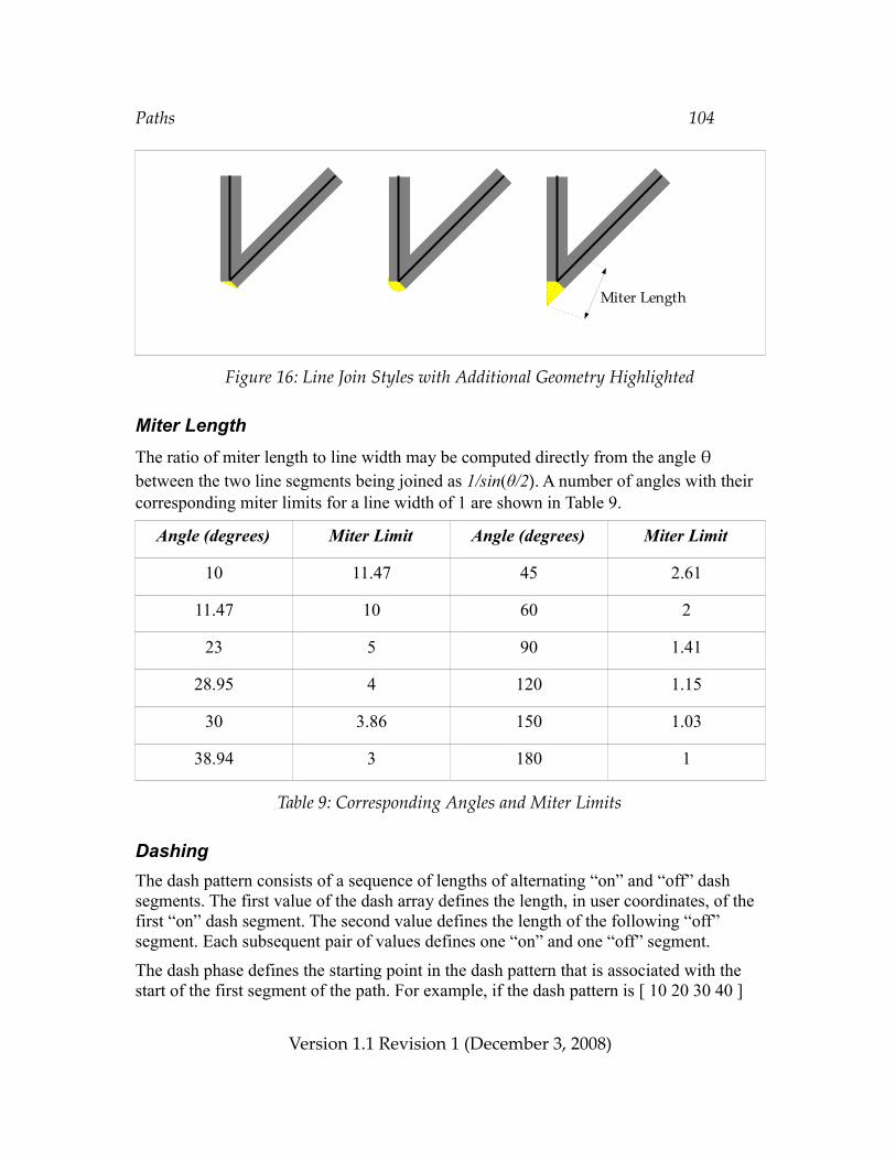
Paths 104
Figure 16: Line Join Styles with Additional Geometry Highlighted
Miter LengthThe ratio of miter length to line width may be computed directly from the angle θ between the two line segments being joined as 1/sin(θ/2). A number of angles with their corresponding miter limits for a line width of 1 are shown in Table 9.
Angle (degrees) Miter Limit Angle (degrees) Miter Limit
10 11.47 45 2.61
11.47 10 60 2
23 5 90 1.41
28.95 4 120 1.15
30 3.86 150 1.03
38.94 3 180 1
Table 9: Corresponding Angles and Miter Limits
DashingThe dash pattern consists of a sequence of lengths of alternating “on” and “off” dash segments. The first value of the dash array defines the length, in user coordinates, of the first “on” dash segment. The second value defines the length of the following “off” segment. Each subsequent pair of values defines one “on” and one “off” segment.
The dash phase defines the starting point in the dash pattern that is associated with the start of the first segment of the path. For example, if the dash pattern is [ 10 20 30 40 ]
Version 1.1 Revision 1 (December 3, 2008)
Miter Length
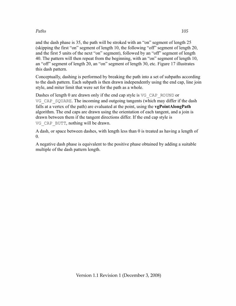
Paths 105
and the dash phase is 35, the path will be stroked with an “on” segment of length 25 (skipping the first “on” segment of length 10, the following “off” segment of length 20, and the first 5 units of the next “on” segment), followed by an “off” segment of length 40. The pattern will then repeat from the beginning, with an “on” segment of length 10, an “off” segment of length 20, an “on” segment of length 30, etc. Figure 17 illustrates this dash pattern.
Conceptually, dashing is performed by breaking the path into a set of subpaths according to the dash pattern. Each subpath is then drawn independently using the end cap, line join style, and miter limit that were set for the path as a whole.
Dashes of length 0 are drawn only if the end cap style is VG_CAP_ROUND or VG_CAP_SQUARE. The incoming and outgoing tangents (which may differ if the dash falls at a vertex of the path) are evaluated at the point, using the vgPointAlongPath algorithm. The end caps are drawn using the orientation of each tangent, and a join is drawn between them if the tangent directions differ. If the end cap style is VG_CAP_BUTT, nothing will be drawn.
A dash, or space between dashes, with length less than 0 is treated as having a length of 0.
A negative dash phase is equivalent to the positive phase obtained by adding a suitable multiple of the dash pattern length.
Version 1.1 Revision 1 (December 3, 2008)
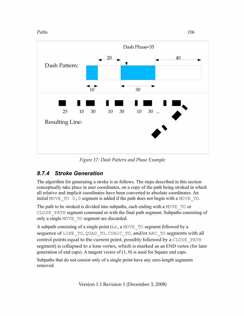
Paths 106
Figure 17: Dash Pattern and Phase Example
8.7.4 Stroke GenerationThe algorithm for generating a stroke is as follows. The steps described in this section conceptually take place in user coordinates, on a copy of the path being stroked in which all relative and implicit coordinates have been converted to absolute coordinates. An initial MOVE_TO 0,0 segment is added if the path does not begin with a MOVE_TO.
The path to be stroked is divided into subpaths, each ending with a MOVE_TO or CLOSE_PATH segment command or with the final path segment. Subpaths consisting of only a single MOVE_TO segment are discarded.
A subpath consisting of a single point (i.e., a MOVE_TO segment followed by a sequence of LINE_TO, QUAD_TO, CUBIC_TO, and/or ARC_TO segments with all control points equal to the current point, possibly followed by a CLOSE_PATH segment) is collapsed to a lone vertex, which is marked as an END vertex (for later generation of end caps). A tangent vector of (1, 0) is used for Square end caps.
Subpaths that do not consist only of a single point have any zero-length segments removed.
Version 1.1 Revision 1 (December 3, 2008)
Dash Phase=35
25 10 30 10 30 10 30 ...
Dash Pattern:
Resulting Line:
10
20
30
40
Paths 107
If a subpath does not end with a CLOSE_PATH segment command, its first and last vertices are marked as END vertices. All the internal vertices that begin or end path segments within the subpath, as well as the initial/final vertex if the subpath ends with a CLOSE_PATH segment, are marked as JOIN vertices (for later generation of line joins).
Each subpath is processed in turn as described below until all subpaths have been stroked.
If dashing is enabled, the dash pattern and phase are used to break the subpath into a series of smaller subpaths representing the “on” portions of the dash pattern. New vertices are created at the endpoints of each dash subpath and marked as END vertices. The old subpath is discarded and replaced with the dash subpaths for the remainder of the stroke processing. The dash phase is advanced for each subsequent segment by the length of the previous segment (where CLOSE_PATH segments are treated as LINE_TO segments). If VG_DASH_PHASE_RESET is disabled (set to VG_FALSE), the final dash phase at the end of the subpath is used as the initial dash phase for the next subpath. Otherwise, the original dash phase is used for all subpaths.
For each END vertex, an end cap is created (if Square or Round end caps have been requested) using the orientation given by the tangent vector. The tangent vector is defined in the same manner as for the vgPointAlongPath function (see p. 92).
For each JOIN vertex, a line join is created using the orientations given by the tangent vectors of the two adjacent path segments. If Miter joins are being used, the length of the miter is computed and compared to the product of the line width and miter limit; if the miter would be too long, a Bevel join is substituted.
8.7.5 Setting Stroke ParametersSetting the line width of a stroke is performed using vgSetf with a paramType argument of VG_STROKE_LINE_WIDTH. A line width less than or equal to 0 prevents stroking from taking place.VGfloat lineWidth;vgSetf(VG_STROKE_LINE_WIDTH, lineWidth);
VGCapStyleThe VGCapStyle enumeration defines constants for the Butt, Round, and Square end cap styles:
Version 1.1 Revision 1 (December 3, 2008)
Paths 108
typedef enum { VG_CAP_BUTT = 0x1700, VG_CAP_ROUND = 0x1701, VG_CAP_SQUARE = 0x1702} VGCapStyle;
Setting the end cap style is performed using vgSeti with a paramType argument of VG_STROKE_CAP_STYLE and a value from the VGCapStyle enumeration.VGCapStyle capStyle;vgSeti(VG_STROKE_CAP_STYLE, capStyle);
VGJoinStyleThe VGJoinStyle enumeration defines constants for the Miter, Round, and Bevel line join styles:typedef enum { VG_JOIN_MITER = 0x1800, VG_JOIN_ROUND = 0x1801, VG_JOIN_BEVEL = 0x1802} VGJoinStyle;
Setting the line join style is performed using vgSeti with a paramType argument of VG_STROKE_JOIN_STYLE and a value from the VGJoinStyle enum.VGJoinStyle joinStyle;vgSeti(VG_STROKE_JOIN_STYLE, joinStyle);
Setting the miter limit is performed using vgSetf with a paramType argument of VG_STROKE_MITER_LIMIT:VGfloat miterLimit;vgSetf(VG_STROKE_MITER_LIMIT, miterLimit);Miter limit values less than 1 are silently clamped to 1.
VG_MAX_DASH_COUNTThe VG_MAX_DASH_COUNT parameter contains the maximum number of dash segments that may be supplied for the VG_STROKE_DASH_PATTERN parameter. All implementations must must support at least 16 dash segments (8 on/off pairs). If there is no implementation-defined limit, a value of VG_MAXINT may be returned. The value may be retrieved by calling vgGeti:VGint maxDashCount = vgGeti(VG_MAX_DASH_COUNT);
Version 1.1 Revision 1 (December 3, 2008)
Paths 109
Setting the Dash PatternThe dash pattern is set using vgSetfv with a paramType argument of VG_STROKE_DASH_PATTERN:VGfloat dashPattern[DASH_COUNT];VGint count = DASH_COUNT;vgSetfv(VG_STROKE_DASH_PATTERN, count, dashPattern);
Dashing may be disabled by calling vgSetfv with a count of 0:vgSetfv(VG_STROKE_DASH_PATTERN, 0, NULL);
The dash phase is set using vgSetf with a paramType argument of VG_STROKE_DASH_PHASE. The resetting behavior of the dash phase when advancing to a new subpath is set using vgSeti with a paramType argument of VG_STROKE_DASH_PHASE_RESET:VGfloat dashPhase;VGboolean dashPhaseReset;vgSetf(VG_STROKE_DASH_PHASE, dashPhase);vgSeti(VG_STROKE_DASH_PHASE_RESET, dashPhaseReset);If the dash pattern has length 0, dashing is not performed. If the dash pattern has an odd number of elements, the final element is ignored. Note that this behavior is different from that defined by SVG; the SVG behavior may be implemented by duplicating the odd-length dash pattern to obtain one with even length.
If more than VG_MAX_DASH_COUNT dashes are specified, those beyond the first VG_MAX_DASH_COUNT are discarded immediately (and will not be returned by vgGet).
8.7.6 Non-Scaling StrokesIn some cases, applications may wish stroked geometry to appear with a particular stroke width in the surface coordinate system, independent of the current user-to-surface transformation. For example, a stroke representing a road on a map might stay the same width as the user zooms in and out of the map, since the stroke width is intended to indicate the type of road (e.g., one-way street, divided road, interstate highway or Autobahn) rather than its true width on the ground.
OpenVG does not provide direct support for this “non-scaling stroke” behavior. However, the behavior may be obtained relatively simply using a combination of features.
If the current user-to-surface transformation consists only of uniform scaling, rotation, and translation (i.e., no shearing or non-uniform scaling), then the stroke width may be
Version 1.1 Revision 1 (December 3, 2008)
Paths 110
set to the desired stroke width in drawing surface coordinates, divided by the scaling factor introduced by the transformation. This scaling factor may be known to the application a priori, or else it may be computed as the square root of the absolute value of the determinant (sx*sy – shx*shy) of the user-to-surface transformation.
If the user-to-surface transformation includes shearing or non-uniform scaling, the geometry to be stroked must be transformed into surface coordinates prior to stroking. The paint transformation must also be set to the concatenation of the paint-to-user and user-to-surface transformations in order to allow correct painting of the stroked geometry. The following code illustrates this technique:VGPath srcPath; /* Path to be drawn with non-scaling stroke */VGPath dstPath; /* Path in drawing surface coordinates */VGfloat strokePaintToUser[9]; /* Paint-to-user transformation */VGfloat pathUserToSurface[9]; /* User-to-surface transformation */
/* Transform the geometry into surface coordinates. */vgSeti(VG_MATRIX_MODE, VG_MATRIX_PATH_USER_TO_SURFACE);vgLoadMatrix(pathUserToSurface);vgTransformPath(dstPath, srcPath);
/* Use the identity matrix for drawing the stroked path. */vgLoadIdentity();
/* Set the paint transformation to the concatenation of the * paint-to-user and user-to-surface transformations. */vgSeti(VG_MATRIX_MODE, VG_MATRIX_FILL_PAINT_TO_USER);vgLoadMatrix(pathUserToSurface);vgMultMatrix(strokePaintToUser);
/* Stroke the transformed path. */vgDrawPath(dstPath, VG_STROKE_PATH);
8.8 Filling or Stroking a Path
VGFillRuleThe VGFillRule enumeration defines constants for the even/odd and non-zero fill rules.typedef enum { VG_EVEN_ODD = 0x1900, VG_NON_ZERO = 0x1901} VGFillRule;
Version 1.1 Revision 1 (December 3, 2008)
Paths 111
To set the rule for filling, call vgSeti with a type parameter value of VG_FILL_RULE and a value parameter defined using a value from the VGFillRule enumeration. When the path is filled, the most recent setting of the fill rule on the current context is used. The fill rule setting has no effect on stroking.VGFillRule fillRule;vgSeti(VG_FILL_RULE, fillRule);
VGPaintModeThe VGPaintMode enumeration defines constants for stroking and filling paths, to be used by the vgDrawPath, vgSetPaint, and vgGetPaint functions.typedef enum { VG_STROKE_PATH = (1 << 0), VG_FILL_PATH = (1 << 1)} VGPaintMode;
vgDrawPathFilling and stroking are performed by the vgDrawPath function. The paintModes argument is a bitwise OR of values from the VGPaintMode enumeration, determining whether the path is to be filled (VG_FILL_PATH), stroked (VG_STROKE_PATH), or both (VG_FILL_PATH | VG_STROKE_PATH). If both filling and stroking are to be performed, the path is first filled, then stroked.void vgDrawPath(VGPath path, VGbitfield paintModes)
ERRORSVG_BAD_HANDLE_ERROR– if path is not a valid path handle, or is not shared with the current contextVG_ILLEGAL_ARGUMENT_ERROR– if paintModes is not a valid bitwise OR of values from the VGPaintMode
enumeration
Filling a PathCalling vgDrawPath with a paintModes argument of VG_FILL_PATH causes the given path to be filled, using the paint defined for the VG_FILL_PATH paint mode and the current fill rule.
Version 1.1 Revision 1 (December 3, 2008)
Paths 112
The matrix currently set for the VG_MATRIX_FILL_PAINT_TO_USER matrix mode is applied to the paint used to fill the path outline. The matrix currently set for the VG_MATRIX_PATH_USER_TO_SURFACE matrix mode is used to transform the outline of the path and the paint into surface coordinates. vgDrawPath(VGPath path, VG_FILL_PATH);
Stroking a PathCalling vgDrawPath with a paintModes argument of VG_STROKE_PATH causes the given path to be stroked, using the paint defined for the VG_STROKE_PATH paint mode and the current set of stroke parameters.
The matrix currently set for the VG_MATRIX_STROKE_PAINT_TO_USER matrix mode is applied to the paint used to fill the stroked path outline. The matrix currently set for the VG_MATRIX_PATH_USER_TO_SURFACE matrix mode is used to transform the outline of the stroked path and the paint into surface coordinates. vgDrawPath(VGPath path, VG_STROKE_PATH);
The following code sample shows how an application might set stroke parameters using variants of vgSet, and stroke a path object (defined elsewhere):VGPath path;
/* Set the line width to 2.5 */vgSetf(VG_STROKE_LINE_WIDTH, 2.5f);/* Set the miter limit to 10.5 */vgSetf(VG_STROKE_MITER_LIMIT, 10.5f);/* Set the cap style to CAP_SQUARE */vgSeti(VG_STROKE_CAP_STYLE, VG_CAP_SQUARE);/* Set the join style to JOIN_MITER */vgSeti(VG_STROKE_JOIN_STYLE, VG_JOIN_MITER);
/* Set the dash pattern */VGfloat dashes[] = { 1.0f, 2.0f, 2.0f, 2.0f };vgSetfv(VG_STROKE_DASH_PATTERN, 4, dashes);
/* Set the dash phase to 0.5 and reset it for every subpath */vgSetf(VG_STROKE_DASH_PHASE, 0.5f);vgSeti(VG_STROKE_DASH_PHASE_RESET, VG_TRUE);
/* Stroke the path */vgDrawPath(path, VG_STROKE_PATH);
Version 1.1 Revision 1 (December 3, 2008)
Paths 113
Filling and Stroking a PathCalling vgDrawPath with a paintModes argument of (VG_FILL_PATH | VG_STROKE_PATH) causes the given path to be first filled, then stroked, exactly as if vgDrawPath were called twice in succession, first with a paintModes argument of VG_FILL_PATH and second with a paintModes argument of VG_STROKE_PATH.vgDrawPath(VGPath path, VG_FILL_PATH | VG_STROKE_PATH);
Version 1.1 Revision 1 (December 3, 2008)
Paint 114
9 PaintPaint defines a color and an alpha value for each pixel being drawn. Color paint defines a constant color for all pixels; gradient paint defines a linear or radial pattern of smoothly varying colors; and pattern paint defines a possibly repeating rectangular pattern of colors based on a source image. It is possible to define new types of paint as extensions.
Paint is defined in its own coordinate system, which is transformed into user coordinates by means of the fill-paint-to-user and stroke-paint-to-user transformations (set using the VG_MATRIX_FILL_PAINT_TO_USER and VG_MATRIX_STROKE_PAINT_TO_USER matrix modes) depending on whether the current geometry is being filled or stroked.
Given a (fill or stroke) paint-to-user transformation Tp and user-to-surface transformation Tu, the paint color and alpha of a pixel to be drawn with surface coordinates (x, y) is defined by mapping its center point (x + ½, y + ½) through the inverse transformation (Tu ◦ Tp)-1, resulting in a sample point in the paint coordinate space. This transformation must be evaluated with sufficient accuracy to ensure a deviation from the ideal of no more than 1/8 of a pixel along either axis. The paint value nearest that point may be used (point sampling), or paint values from multiple points surrounding the central sample point may be combined to produce an interpolated paint value. Paint color values are processed in premultiplied alpha format during interpolation. The user-to-surface transformation Tu is taken from the path-user-to-surface transformation when fulfilling a vgDrawPath call, from the image-user-to-surface transformation when fulfilling a vgDrawImage call, or from the glyph-user-to-surface transformation when fulfilling a vgDrawGlyph or vgDrawGlyphs call.
If the inverse transformation cannot be computed due to a (near-)singularity, no drawing occurs.
9.1 Paint DefinitionsThe OpenVG context stores two paint definitions at a time, one to be applied to stroked shapes and one for filled shapes. This allows the interior of a path to be filled using one type of paint and its outline to be stroked with another kind of paint in a single vgDrawPath operation. Initially, default values are used.
VGPaintVGPaint represents an opaque handle to a paint object. A VGPaint object is live; changes to a VGPaint object (using vgSetParameter, or by altering an attached
Version 1.1 Revision 1 (December 3, 2008)
Paint 115
pattern image) attached to a context will immediately affect drawing calls on that context. If a VGPaint object is accessed from multiple threads, the application must ensure (using vgFinish along with application-level synchronization primitives) that the paint definition is not altered from one context while another context may still be using it for drawing.typedef VGHandle VGPaint;
9.1.1 Creating and Destroying Paint Objects
vgCreatePaintvgCreatePaint creates a new paint object that is initialized to a set of default values and returns a VGPaint handle to it. If insufficient memory is available to allocate a new object, VG_INVALID_HANDLE is returned.VGPaint vgCreatePaint(void)
vgDestroyPaintThe resources associated with a paint object may be deallocated by calling vgDestroyPaint. Following the call, the paint handle is no longer valid in any of the contexts that shared it. If the paint object is currently active in a drawing context, the context continues to access it until it is replaced or the context is destroyed.void vgDestroyPaint(VGPaint paint)
ERRORSVG_BAD_HANDLE_ERROR– if paint is not a valid paint handle, or is not shared with the current context
9.1.2 Setting the Current Paint
vgSetPaintPaint definitions are set on the current context using the vgSetPaint function. The paintModes argument is a bitwise OR of values from the VGPaintMode enumeration, determining whether the paint object is to be used for filling
Version 1.1 Revision 1 (December 3, 2008)
Paint 116
(VG_FILL_PATH), stroking (VG_STROKE_PATH), or both (VG_FILL_PATH | VG_STROKE_PATH). The current paint replaces the previously set paint object, if any, for the given paint mode or modes. If paint is equal to VG_INVALID_HANDLE, the previously set paint object for the given mode (if present) is removed and the paint settings are restored to their default values.void vgSetPaint(VGPaint paint, VGbitfield paintModes)
Version 1.1 Revision 1 (December 3, 2008)
Paint 117
ERRORSVG_BAD_HANDLE_ERROR– if paint is neither a valid paint handle nor equal to VG_INVALID_HANDLE,
or is not shared with the current contextVG_ILLEGAL_ARGUMENT_ERROR– if paintModes is not a valid bitwise OR of values from the VGPaintMode
enumeration
vgGetPaintThe vgGetPaint function returns the paint object currently set for the given paintMode, or VG_INVALID_HANDLE if an error occurs or if no paint object is set (i.e., the default paint is present) on the given context with the given paintMode.VGPaint vgGetPaint(VGPaintMode paintMode)
ERRORSVG_ILLEGAL_ARGUMENT_ERROR– if paintMode is not a valid value from the VGPaintMode enumeration
9.1.3 Setting Paint ParametersPaint functionality is controlled by a number of paint parameters that are stored in each paint object.
VGPaintParamTypeValues from the VGPaintParamType enumeration may be used as the paramType argument to vgSetParameter and vgGetParameter to set and query various features of a paint object:
Version 1.1 Revision 1 (December 3, 2008)
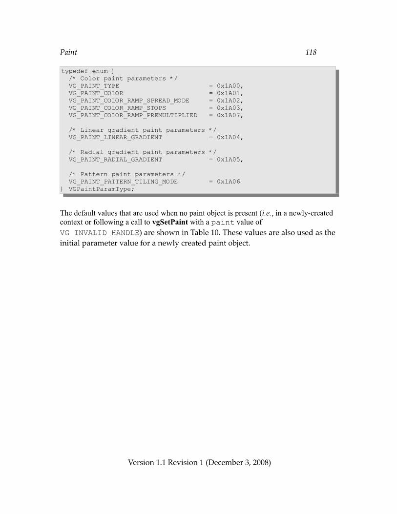
Paint 118
typedef enum { /* Color paint parameters */ VG_PAINT_TYPE = 0x1A00, VG_PAINT_COLOR = 0x1A01, VG_PAINT_COLOR_RAMP_SPREAD_MODE = 0x1A02, VG_PAINT_COLOR_RAMP_STOPS = 0x1A03, VG_PAINT_COLOR_RAMP_PREMULTIPLIED = 0x1A07,
/* Linear gradient paint parameters */ VG_PAINT_LINEAR_GRADIENT = 0x1A04,
/* Radial gradient paint parameters */ VG_PAINT_RADIAL_GRADIENT = 0x1A05,
/* Pattern paint parameters */ VG_PAINT_PATTERN_TILING_MODE = 0x1A06} VGPaintParamType;
The default values that are used when no paint object is present (i.e., in a newly-created context or following a call to vgSetPaint with a paint value of VG_INVALID_HANDLE) are shown in Table 10. These values are also used as the initial parameter value for a newly created paint object.
Version 1.1 Revision 1 (December 3, 2008)
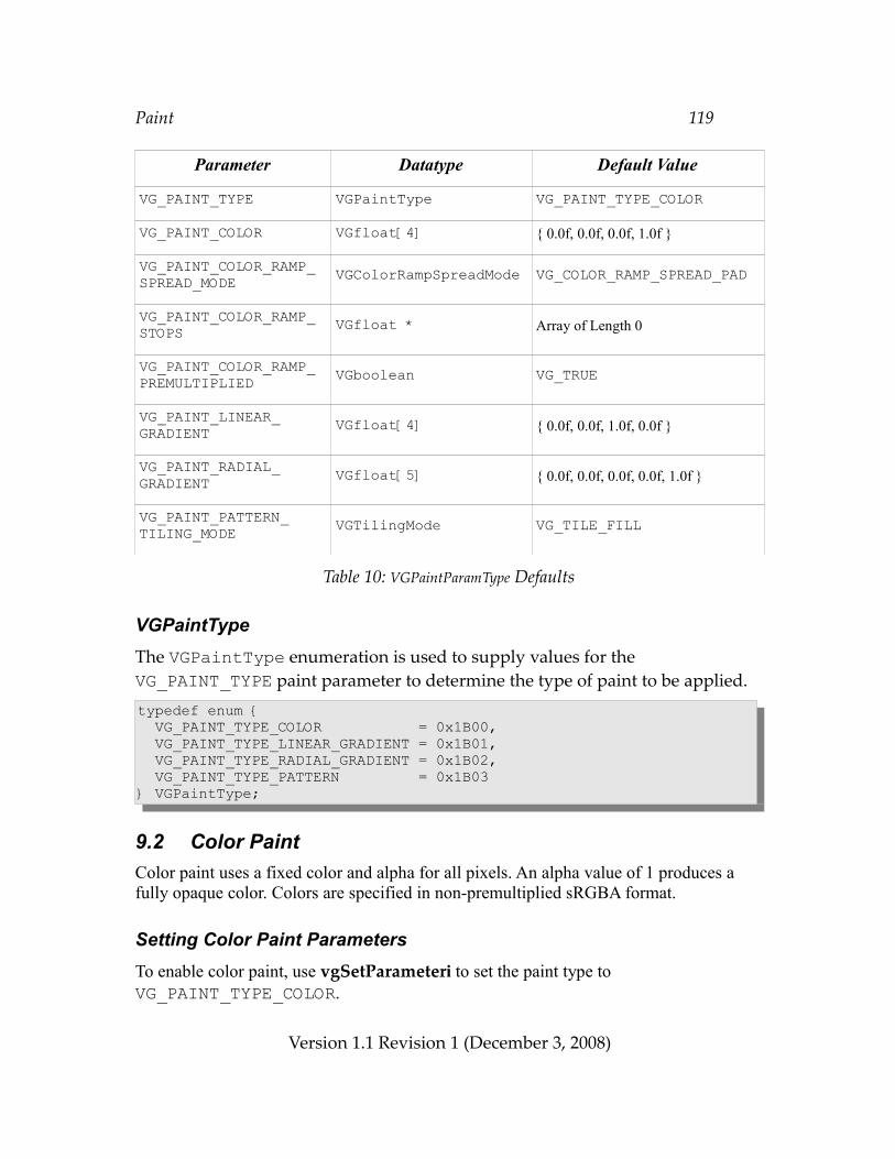
Paint 119
Parameter Datatype Default Value
VG_PAINT_TYPE VGPaintType VG_PAINT_TYPE_COLOR
VG_PAINT_COLOR VGfloat[4] { 0.0f, 0.0f, 0.0f, 1.0f }
VG_PAINT_COLOR_RAMP_SPREAD_MODE VGColorRampSpreadMode VG_COLOR_RAMP_SPREAD_PAD
VG_PAINT_COLOR_RAMP_STOPS VGfloat * Array of Length 0
VG_PAINT_COLOR_RAMP_PREMULTIPLIED VGboolean VG_TRUE
VG_PAINT_LINEAR_GRADIENT VGfloat[4] { 0.0f, 0.0f, 1.0f, 0.0f }
VG_PAINT_RADIAL_GRADIENT VGfloat[5] { 0.0f, 0.0f, 0.0f, 0.0f, 1.0f }
VG_PAINT_PATTERN_TILING_MODE VGTilingMode VG_TILE_FILL
Table 10: VGPaintParamType Defaults
VGPaintTypeThe VGPaintType enumeration is used to supply values for the VG_PAINT_TYPE paint parameter to determine the type of paint to be applied.typedef enum { VG_PAINT_TYPE_COLOR = 0x1B00, VG_PAINT_TYPE_LINEAR_GRADIENT = 0x1B01, VG_PAINT_TYPE_RADIAL_GRADIENT = 0x1B02, VG_PAINT_TYPE_PATTERN = 0x1B03} VGPaintType;
9.2 Color PaintColor paint uses a fixed color and alpha for all pixels. An alpha value of 1 produces a fully opaque color. Colors are specified in non-premultiplied sRGBA format.
Setting Color Paint ParametersTo enable color paint, use vgSetParameteri to set the paint type to VG_PAINT_TYPE_COLOR.
Version 1.1 Revision 1 (December 3, 2008)
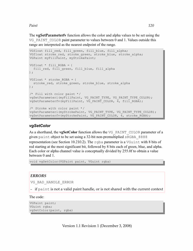
Paint 120
The vgSetParameterfv function allows the color and alpha values to be set using the VG_PAINT_COLOR paint parameter to values between 0 and 1. Values outside this range are interpreted as the nearest endpoint of the range.VGfloat fill_red, fill_green, fill_blue, fill_alpha;VGfloat stroke_red, stroke_green, stroke_blue, stroke_alpha;VGPaint myFillPaint, myStrokePaint;
VGfloat * fill_RGBA = { fill_red, fill_green, fill_blue, fill_alpha};
VGfloat * stroke_RGBA = { stroke_red, stroke_green, stroke_blue, stroke_alpha};
/* Fill with color paint */vgSetParameteri(myFillPaint, VG_PAINT_TYPE, VG_PAINT_TYPE_COLOR);vgSetParameterfv(myFillPaint, VG_PAINT_COLOR, 4, fill_RGBA);
/* Stroke with color paint */vgSetParameteri(myStrokePaint, VG_PAINT_TYPE, VG_PAINT_TYPE_COLOR);vgSetParameterfv(myStrokePaint, VG_PAINT_COLOR, 4, stroke_RGBA);
vgSetColorAs a shorthand, the vgSetColor function allows the VG_PAINT_COLOR parameter of a given paint object to be set using a 32-bit non-premultiplied sRGBA_8888 representation (see Section 10.210.2). The rgba parameter is a VGuint with 8 bits of red starting at the most significant bit, followed by 8 bits each of green, blue, and alpha. Each color or alpha channel value is conceptually divided by 255.0f to obtain a value between 0 and 1.void vgSetColor(VGPaint paint, VGuint rgba)
ERRORSVG_BAD_HANDLE_ERROR– if paint is not a valid paint handle, or is not shared with the current context
The code:VGPaint paint;VGuint rgba;vgSetColor(paint, rgba)
Version 1.1 Revision 1 (December 3, 2008)
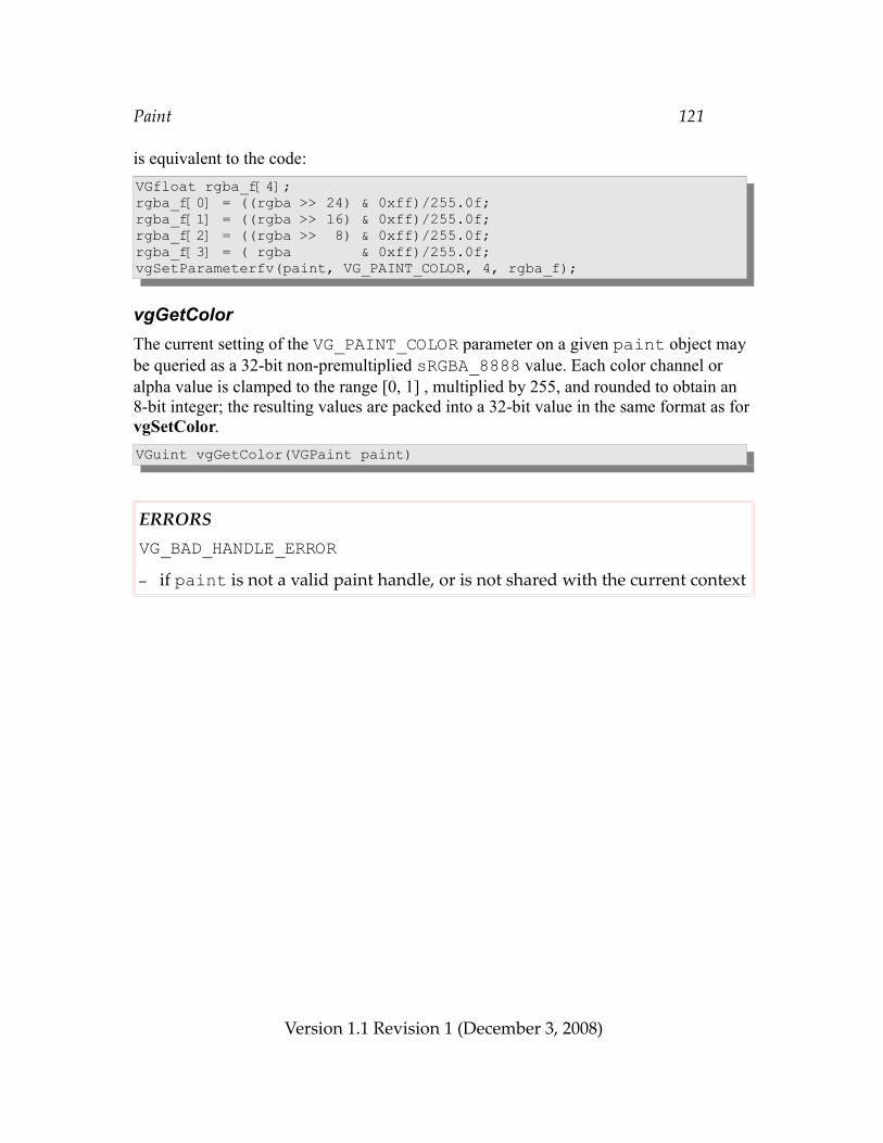
Paint 121
is equivalent to the code:VGfloat rgba_f[4];rgba_f[0] = ((rgba >> 24) & 0xff)/255.0f;rgba_f[1] = ((rgba >> 16) & 0xff)/255.0f;rgba_f[2] = ((rgba >> 8) & 0xff)/255.0f;rgba_f[3] = ( rgba & 0xff)/255.0f;vgSetParameterfv(paint, VG_PAINT_COLOR, 4, rgba_f);
vgGetColorThe current setting of the VG_PAINT_COLOR parameter on a given paint object may be queried as a 32-bit non-premultiplied sRGBA_8888 value. Each color channel or alpha value is clamped to the range [0, 1] , multiplied by 255, and rounded to obtain an 8-bit integer; the resulting values are packed into a 32-bit value in the same format as for vgSetColor.VGuint vgGetColor(VGPaint paint)
ERRORSVG_BAD_HANDLE_ERROR– if paint is not a valid paint handle, or is not shared with the current context
Version 1.1 Revision 1 (December 3, 2008)
Paint 122
The code:VGPaint paint;VGuint rgba;rgba = vgGetColor(paint);is equivalent to the code:#define CLAMP(x) ((x) < 0.0f ? 0.0f : ((x) > 1.0f ? 1.0f : (x)))
VGfloat rgba_f[4];int red, green, blue, alpha;
vgGetParameterfv(paint, VG_PAINT_COLOR, 4, rgba_f);
/* * Clamp color and alpha values from vgGetParameterfv to the * [0, 1] range, scale to 8 bits, and round to integer. */red = (int)(CLAMP(rgba_f[0])*255.0f + 0.5f);green = (int)(CLAMP(rgba_f[1])*255.0f + 0.5f);blue = (int)(CLAMP(rgba_f[2])*255.0f + 0.5f);alpha = (int)(CLAMP(rgba_f[3])*255.0f + 0.5f);rgba = (red << 24) | (green << 16) | (blue << 8) | alpha;
9.3 Gradient PaintGradients are patterns used for filling or stroking. They are defined mathematically in two parts; a scalar-valued gradient function defined at every point in the two-dimensional plane (in paint coordinates), followed by a color ramp mapping.
9.3.1 Linear GradientsLinear gradients define a scalar-valued gradient function based on two points (x0, y0) and (x1, y1) (in the paint coordinate system) with the following properties:
• It is equal to 0 at (x0, y0)• It is equal to 1 at (x1, y1)• It increases linearly along the line from (x0, y0) to (x1, y1) • It is constant along lines perpendicular to the line from (x0, y0) to (x1, y1)
An expression for the gradient function is:
Version 1.1 Revision 1 (December 3, 2008)
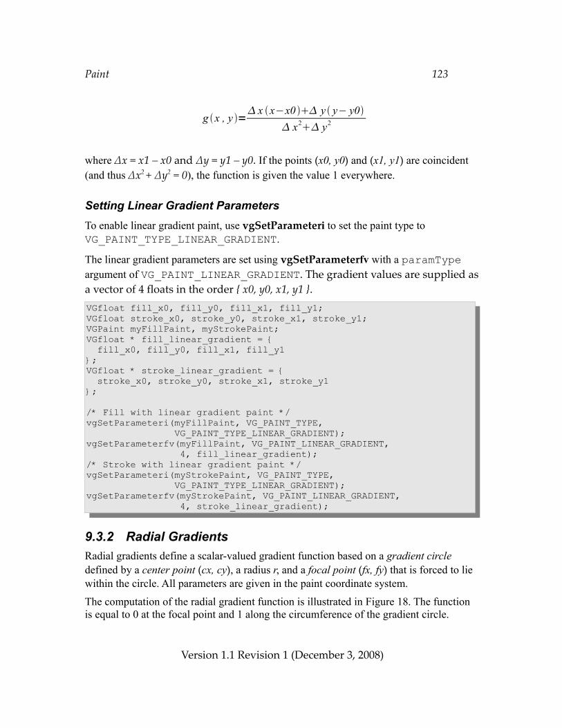
Paint 123
where Δx = x1 – x0 and Δy = y1 – y0. If the points (x0, y0) and (x1, y1) are coincident (and thus Δx2 + Δy2 = 0), the function is given the value 1 everywhere.
Setting Linear Gradient ParametersTo enable linear gradient paint, use vgSetParameteri to set the paint type to VG_PAINT_TYPE_LINEAR_GRADIENT.
The linear gradient parameters are set using vgSetParameterfv with a paramType argument of VG_PAINT_LINEAR_GRADIENT. The gradient values are supplied as a vector of 4 floats in the order { x0, y0, x1, y1 }.VGfloat fill_x0, fill_y0, fill_x1, fill_y1;VGfloat stroke_x0, stroke_y0, stroke_x1, stroke_y1;VGPaint myFillPaint, myStrokePaint;VGfloat * fill_linear_gradient = { fill_x0, fill_y0, fill_x1, fill_y1};VGfloat * stroke_linear_gradient = { stroke_x0, stroke_y0, stroke_x1, stroke_y1};
/* Fill with linear gradient paint */vgSetParameteri(myFillPaint, VG_PAINT_TYPE, VG_PAINT_TYPE_LINEAR_GRADIENT);vgSetParameterfv(myFillPaint, VG_PAINT_LINEAR_GRADIENT, 4, fill_linear_gradient);/* Stroke with linear gradient paint */vgSetParameteri(myStrokePaint, VG_PAINT_TYPE, VG_PAINT_TYPE_LINEAR_GRADIENT);vgSetParameterfv(myStrokePaint, VG_PAINT_LINEAR_GRADIENT, 4, stroke_linear_gradient);
9.3.2 Radial GradientsRadial gradients define a scalar-valued gradient function based on a gradient circle defined by a center point (cx, cy), a radius r, and a focal point (fx, fy) that is forced to lie within the circle. All parameters are given in the paint coordinate system.
The computation of the radial gradient function is illustrated in Figure 18. The function is equal to 0 at the focal point and 1 along the circumference of the gradient circle.
Version 1.1 Revision 1 (December 3, 2008)
g x , y = x x−x0 y y− y0
x2 y2
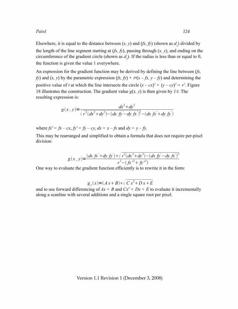
Paint 124
Elsewhere, it is equal to the distance between (x, y) and (fx, fy) (shown as d1) divided by
the length of the line segment starting at (fx, fy), passing through (x, y), and ending on the circumference of the gradient circle (shown as d2). If the radius is less than or equal to 0, the function is given the value 1 everywhere.
An expression for the gradient function may be derived by defining the line between (fx, fy) and (x, y) by the parametric expression (fx, fy) + t*(x – fx, y – fy) and determining the positive value of t at which the line intersects the circle (x – cx)2 + (y – cy)2 = r2. Figure18 illustrates the construction. The gradient value g(x, y) is then given by 1/t. The resulting expression is:
where fx' = fx – cx, fy' = fy – cy, dx = x – fx and dy = y – fy.
This may be rearranged and simplified to obtain a formula that does not require per-pixel division:
One way to evaluate the gradient function efficiently is to rewrite it in the form:
and to use forward differencing of Ax + B and Cx2 + Dx + E to evaluate it incrementally along a scanline with several additions and a single square root per pixel.
Version 1.1 Revision 1 (December 3, 2008)
g x , y =dx fx 'dy fy' r2dx 2dy2−dx fy'−dy fx' 2
r 2− fx ' 2 fy ' 2
g x , y = dx2dy2
r 2dx2dy2−dx fy'−dy fx ' 2−dx fx 'dy fy'
g y x =A xB C x2D xE
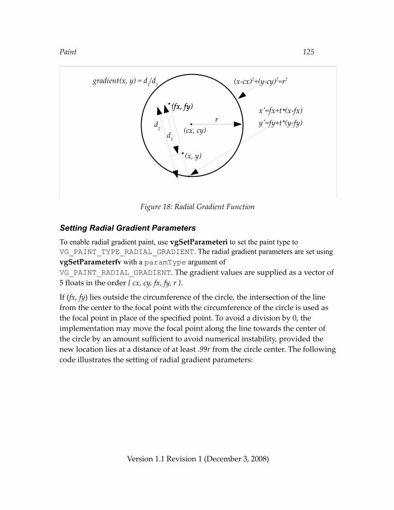
Paint 125
Figure 18: Radial Gradient Function
Setting Radial Gradient ParametersTo enable radial gradient paint, use vgSetParameteri to set the paint type to VG_PAINT_TYPE_RADIAL_GRADIENT. The radial gradient parameters are set using vgSetParameterfv with a paramType argument of VG_PAINT_RADIAL_GRADIENT. The gradient values are supplied as a vector of 5 floats in the order { cx, cy, fx, fy, r }.
If (fx, fy) lies outside the circumference of the circle, the intersection of the line from the center to the focal point with the circumference of the circle is used as the focal point in place of the specified point. To avoid a division by 0, the implementation may move the focal point along the line towards the center of the circle by an amount sufficient to avoid numerical instability, provided the new location lies at a distance of at least .99r from the circle center. The following code illustrates the setting of radial gradient parameters:
Version 1.1 Revision 1 (December 3, 2008)
(cx, cy)
(fx, fy)
r
(x, y)
d2
d1
gradient(x, y) = d1/d
2
(fx, fy)
(x-cx)2+(y-cy)2=r2
x'=fx+t*(x-fx)y'=fy+t*(y-fy)
Paint 126
VGPaint myFillPaint, myStrokePaint;VGfloat fill_cx, fill_cy, fill_fx, fill_fy, fill_r;VGfloat stroke_cx, stroke_cy, stroke_fx, stroke_fy, stroke_r;VGfloat * fill_radial_gradient = { fill_cx, fill_cy, fill_fx, fill_fy, fill_r };VGfloat * stroke_radial_gradient = { stroke_cx, stroke_cy, stroke_fx, stroke_fy, stroke_r };vgSetParameteri(myFillPaint, VG_PAINT_TYPE, /* Fill */ VG_PAINT_TYPE_RADIAL_GRADIENT);vgSetParameterfv(myFillPaint, VG_PAINT_RADIAL_GRADIENT, 5, fill_radial_gradient);vgSetParameteri(myStrokePaint, VG_PAINT_TYPE, /* Stroke */ VG_PAINT_TYPE_RADIAL_GRADIENT);vgSetParameterfv(myStrokePaint, VG_PAINT_RADIAL_GRADIENT, 5, stroke_radial_gradient);
9.3.3 Color RampsColor ramps map the scalar values produced by gradient functions to colors. The application defines the non-premultiplied sRGBA color and alpha value associated with each of a number of values, called stops. A stop is defined by an offset between 0 and 1, inclusive, and a color value. Stops must be specified in increasing order; if they are not, the entire sequence is ignored. It is legal to have multiple stops with the same offset value, which will result in a discontinuity in the color ramp, with the first stop with a given offset value defining the right endpoint of one interval and the last stop with the same offset value defining the left endpoint of the next interval. At an offset value equal to that of a stop, the color value is that of the last stop with the given offset. Intermediate stops with the same offset value have no effect. Stops with offsets less than 0 or greater than 1 are ignored.
If no valid stops have been specified (e.g., due to an empty input array, out-of-range, or out-of-order stops), a stop at 0 with (R, G, B, α) color (0.0, 0.0, 0.0, 1.0) (opaque black) and a stop at 1 with color (1.0, 1.0, 1.0, 1.0) (opaque white) are implicitly defined. If at least one valid stop has been specified, but none has been defined with an offset of 0, an implicit stop is added with an offset of 0 and the same color as the first user-defined stop. If at least one valid stop has been specified, but none has been defined with an offset of 1, an implicit stop is added with an offset of 1 and the same color as the last user-defined stop.
If a color or alpha value of a given stop falls outside of the range [0, 1], the closest endpoint of the range is used instead.
If the paint’s VG_PAINT_COLOR_RAMP_PREMULTIPLIED flag is set to VG_TRUE, color and alpha values at each gradient stop are multiplied together to form premultiplied sRGBA values prior to interpolation. Otherwise, color and alpha values are processed independently.
Version 1.1 Revision 1 (December 3, 2008)
Paint 127
Color and alpha values at offset values between the stops are defined by means of linear interpolation between the premultiplied or non-premultiplied color values defined at the nearest stops above and below the given offset value.
VG_MAX_COLOR_RAMP_STOPSThe VG_MAX_COLOR_RAMP_STOPS parameter contains the maximum number of gradient stops supported by the OpenVG implementation. All implementations must support at least 32 stops. If there is no implementation-defined limit, a value of VG_MAXINT may be returned. Implicitly defined stops at offsets 0 and 1 are not counted against this maximum. The value may be retrieved by calling vgGeti:VGint maxStops = vgGeti(VG_MAX_COLOR_RAMP_STOPS);
VGColorRampSpreadModeThe application may only define stops with offsets between 0 and 1. Spread modes define how the given set of stops are repeated or extended in order to define interpolated color values for arbitrary input values outside the [0,1] range. The VGColorRampSpreadMode enumeration defines three modes:
• VG_COLOR_RAMP_SPREAD_PAD – extend stops • VG_COLOR_RAMP_SPREAD_REPEAT – repeat stops• VG_COLOR_RAMP_SPREAD_REFLECT – repeat stops in reflected order
typedef enum { VG_COLOR_RAMP_SPREAD_PAD = 0x1C00, VG_COLOR_RAMP_SPREAD_REPEAT = 0x1C01, VG_COLOR_RAMP_SPREAD_REFLECT = 0x1C02} VGColorRampSpreadMode;
In pad mode, the colors defined at 0 and 1 are used for all stop values less than 0 or greater than 1, respectively.
In repeat mode, the color values defined between 0 and 1 are repeated indefinitely in both directions. Gradient values outside the [0, 1] range are shifted by an integer amount to place them into that range. For example, a gradient value of 5.6 will receive the same color as a gradient value of 0.6. A gradient value of -5.6 will receive the same color as a gradient value of 0.4 (since 0.4 = -5.6 + 6).
In reflect mode, the color values defined between 0 and 1 are repeated indefinitely in both directions, but with alternate copies of the range reversed. A gradient value of 1.2 will receive the same color as a gradient value of 0.8, since 0.8 = 1.0 – 0.2 and 1.2 = 1.0 + 0.2. A gradient value of 2.4 will receive the same color as a gradient value
Version 1.1 Revision 1 (December 3, 2008)
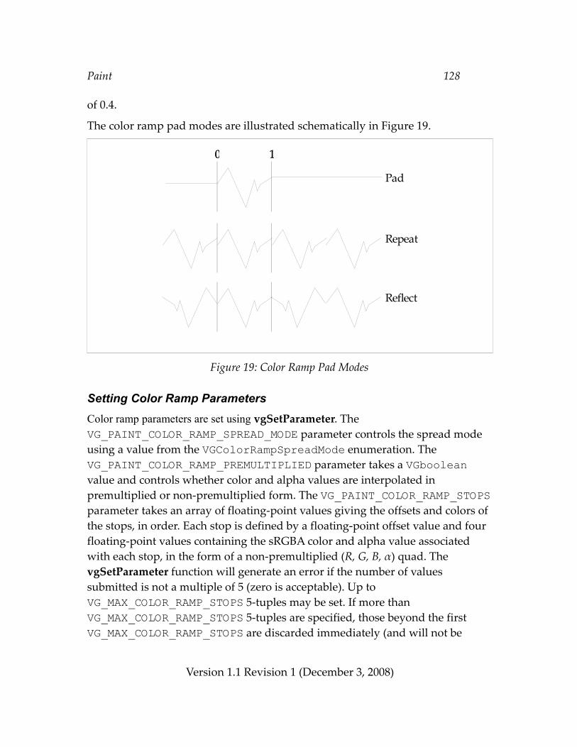
Paint 128
of 0.4.
The color ramp pad modes are illustrated schematically in Figure 19.
Figure 19: Color Ramp Pad Modes
Setting Color Ramp ParametersColor ramp parameters are set using vgSetParameter. The VG_PAINT_COLOR_RAMP_SPREAD_MODE parameter controls the spread mode using a value from the VGColorRampSpreadMode enumeration. The VG_PAINT_COLOR_RAMP_PREMULTIPLIED parameter takes a VGboolean value and controls whether color and alpha values are interpolated in premultiplied or non-premultiplied form. The VG_PAINT_COLOR_RAMP_STOPS parameter takes an array of floating-point values giving the offsets and colors of the stops, in order. Each stop is defined by a floating-point offset value and four floating-point values containing the sRGBA color and alpha value associated with each stop, in the form of a non-premultiplied (R, G, B, α) quad. The vgSetParameter function will generate an error if the number of values submitted is not a multiple of 5 (zero is acceptable). Up to VG_MAX_COLOR_RAMP_STOPS 5-tuples may be set. If more than VG_MAX_COLOR_RAMP_STOPS 5-tuples are specified, those beyond the first VG_MAX_COLOR_RAMP_STOPS are discarded immediately (and will not be
Version 1.1 Revision 1 (December 3, 2008)
0 10 1
Pad
Repeat
Reflect
Paint 129
returned by vgGetParameter).VGPaint myFillPaint, myStrokePaint;
VGColorRampSpreadMode fill_spreadMode;VGboolean fill_premultiplied;VGfloat fill_stops[5*FILL_NUM_STOPS];
VGColorRampSpreadMode stroke_spreadMode;VGboolean stroke_premultiplied;VGfloat stroke_stops[5*STROKE_NUM_STOPS];
vgSetParameteri(myFillPaint, VG_PAINT_COLOR_RAMP_SPREAD_MODE, fill_spreadMode);vgSetParameteri(myFillPaint, VG_PAINT_COLOR_RAMP_PREMULTIPLIED, fill_premultiplied);vgSetParameterfv(myFillPaint, VG_PAINT_COLOR_RAMP_STOPS, 5*FILL_NUM_STOPS, fill_stops);
vgSetParameteri(myStrokePaint, VG_PAINT_COLOR_RAMP_SPREAD_MODE, stroke_spreadMode);vgSetParameteri(myStrokePaint, VG_PAINT_COLOR_RAMP_PREMULTIPLIED, stroke_premultiplied);vgSetParameterfv(myStrokePaint, VG_PAINT_COLOR_RAMP_STOPS, 5*STROKE_NUM_STOPS, stroke_stops);
A common set of color ramp settings are used for both linear and radial gradients defined on a given paint object.
Formal Definition of Spread ModesThis section provides a formal definition of the color ramp spread modes.
In the following, assume that a sequence of stops {S0, S1, ..., SN-1} have been defined by the application, and/or by default or implicit values. The stop Si is defined to have offset xi and color ci. The stops are assumed to be ordered by offset but may have duplicate offsets; that is, for all i < j, xi ≤ xj. To determine the interpolated color value at a given offset value v, determine the smallest i such that xi+1 > v. If xi = v, use the color ci, otherwise perform linear interpolation between the stops Si and Si+1 to produce the color ci + (ci+1 – ci)(v – xi)/(xi+1 – xi).
In pad mode, values smaller than 0 are assigned the color c0 and values greater than or equal to 1 are assigned the color cN-1.
In repeat mode, the offset value v is mapped to a new value v´ that is guaranteed to lie between 0 and 1. Following this mapping, the color is defined as for pad mode:
Version 1.1 Revision 1 (December 3, 2008)
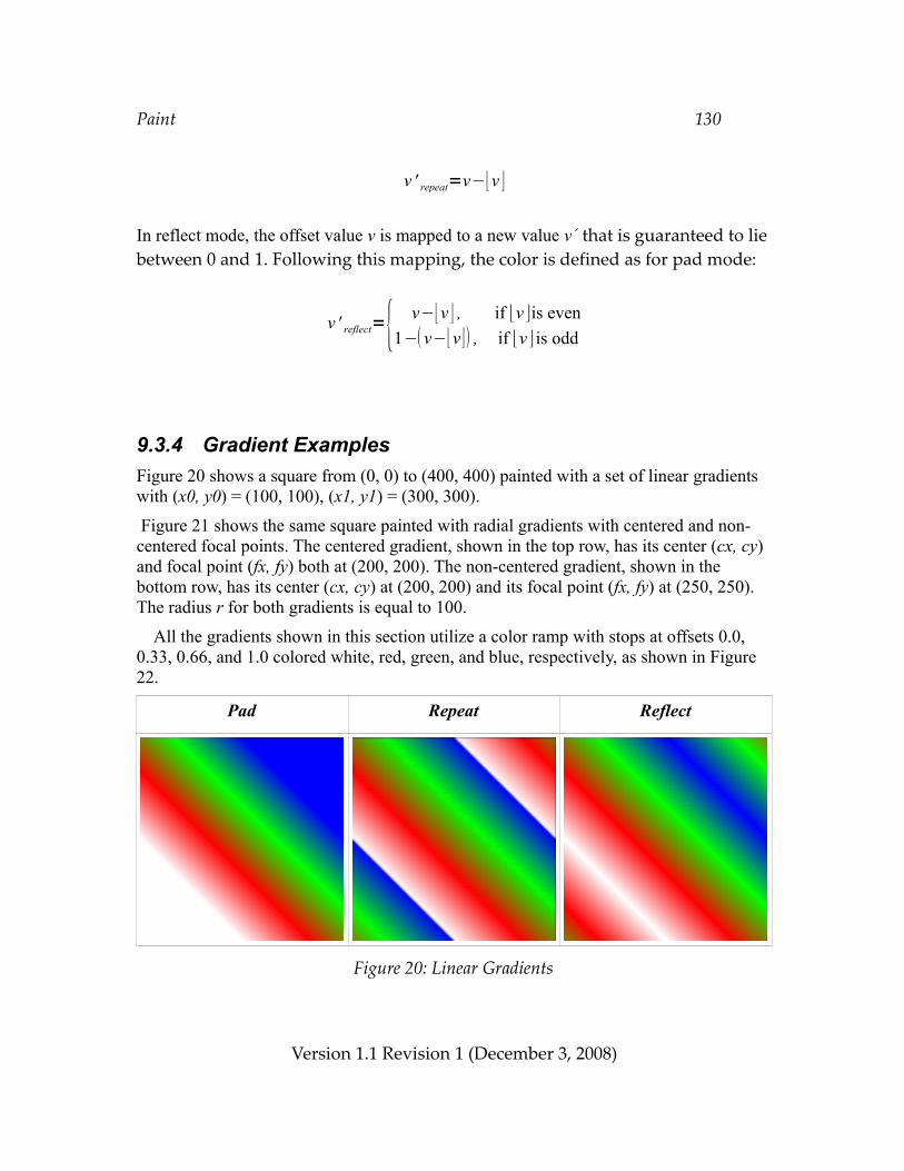
Paint 130
In reflect mode, the offset value v is mapped to a new value v´ that is guaranteed to lie between 0 and 1. Following this mapping, the color is defined as for pad mode:
9.3.4 Gradient ExamplesFigure 20 shows a square from (0, 0) to (400, 400) painted with a set of linear gradients with (x0, y0) = (100, 100), (x1, y1) = (300, 300).
Figure 21 shows the same square painted with radial gradients with centered and non-centered focal points. The centered gradient, shown in the top row, has its center (cx, cy) and focal point (fx, fy) both at (200, 200). The non-centered gradient, shown in the bottom row, has its center (cx, cy) at (200, 200) and its focal point (fx, fy) at (250, 250). The radius r for both gradients is equal to 100.
All the gradients shown in this section utilize a color ramp with stops at offsets 0.0, 0.33, 0.66, and 1.0 colored white, red, green, and blue, respectively, as shown in Figure22.
Pad Repeat Reflect
Figure 20: Linear Gradients
Version 1.1 Revision 1 (December 3, 2008)
v ' reflect={ v−⌊v ⌋ , if ⌊v ⌋is even1− v−⌊v⌋ , if ⌊v ⌋ is odd
v ' repeat=v−⌊v ⌋
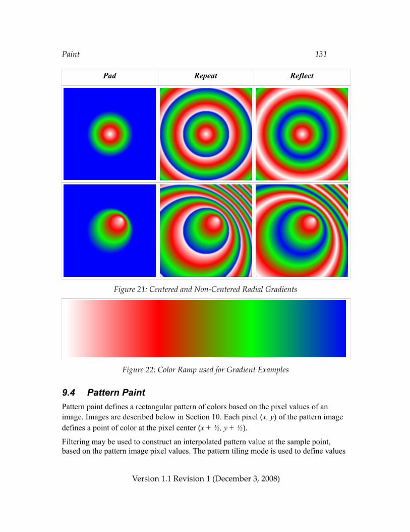
Paint 131
Pad Repeat Reflect
Figure 21: Centered and Non-Centered Radial Gradients
Figure 22: Color Ramp used for Gradient Examples
9.4 Pattern PaintPattern paint defines a rectangular pattern of colors based on the pixel values of an image. Images are described below in Section 10. Each pixel (x, y) of the pattern image defines a point of color at the pixel center (x + ½, y + ½).
Filtering may be used to construct an interpolated pattern value at the sample point, based on the pattern image pixel values. The pattern tiling mode is used to define values
Version 1.1 Revision 1 (December 3, 2008)
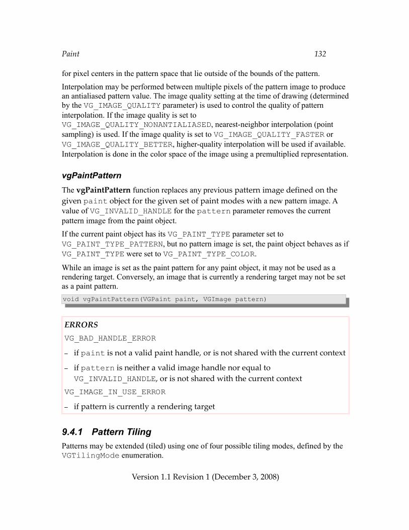
Paint 132
for pixel centers in the pattern space that lie outside of the bounds of the pattern.
Interpolation may be performed between multiple pixels of the pattern image to produce an antialiased pattern value. The image quality setting at the time of drawing (determined by the VG_IMAGE_QUALITY parameter) is used to control the quality of pattern interpolation. If the image quality is set to VG_IMAGE_QUALITY_NONANTIALIASED, nearest-neighbor interpolation (point sampling) is used. If the image quality is set to VG_IMAGE_QUALITY_FASTER or VG_IMAGE_QUALITY_BETTER, higher-quality interpolation will be used if available. Interpolation is done in the color space of the image using a premultiplied representation.
vgPaintPatternThe vgPaintPattern function replaces any previous pattern image defined on the given paint object for the given set of paint modes with a new pattern image. A value of VG_INVALID_HANDLE for the pattern parameter removes the current pattern image from the paint object.
If the current paint object has its VG_PAINT_TYPE parameter set to VG_PAINT_TYPE_PATTERN, but no pattern image is set, the paint object behaves as if VG_PAINT_TYPE were set to VG_PAINT_TYPE_COLOR.
While an image is set as the paint pattern for any paint object, it may not be used as a rendering target. Conversely, an image that is currently a rendering target may not be set as a paint pattern.void vgPaintPattern(VGPaint paint, VGImage pattern)
ERRORSVG_BAD_HANDLE_ERROR– if paint is not a valid paint handle, or is not shared with the current context
– if pattern is neither a valid image handle nor equal to VG_INVALID_HANDLE, or is not shared with the current context
VG_IMAGE_IN_USE_ERROR– if pattern is currently a rendering target
9.4.1 Pattern TilingPatterns may be extended (tiled) using one of four possible tiling modes, defined by the VGTilingMode enumeration.
Version 1.1 Revision 1 (December 3, 2008)
Paint 133
VGTilingModeThe VGTilingMode enumeration defines possible methods for defining colors for source pixels that lie outside the bounds of the source image.
The VG_TILE_FILL condition specifies that pixels outside the bounds of the source image should be taken as the color VG_TILE_FILL_COLOR. The color is expressed as a non-premultiplied sRGBA color and alpha value. Values outside the [0, 1] range are interpreted as the nearest endpoint of the range.
The VG_TILE_PAD condition specifies that pixels outside the bounds of the source image should be taken as having the same color as the closest edge pixel of the source image. That is, a pixel (x, y) has the same value as the image pixel (max(0, min(x, width – 1)), max(0, min(y, height – 1))).
The VG_TILE_REPEAT condition specifies that the source image should be repeated indefinitely in all directions. That is, a pixel (x, y) has the same value as the image pixel (x mod width, y mod height) where the operator ‘a mod b’ returns a value between 0 and (b – 1) such that a = k*b + (a mod b) for some integer k.
The VG_TILE_REFLECT condition specifies that the source image should be reflected indefinitely in all directions. That is, a pixel (x, y) has the same value as the image pixel (x’, y’) where:
x’ = x mod width if floor(x/width) is even,
width – 1 – (x mod width) otherwise.
y’ = y mod height if floor(y/height) is even,
height – 1 – (y mod height) otherwise.
typedef enum { VG_TILE_FILL = 0x1D00, VG_TILE_PAD = 0x1D01, VG_TILE_REPEAT = 0x1D02, VG_TILE_REFLECT = 0x1D03,} VGTilingMode;
Setting the Pattern Tiling ModeThe pattern tiling mode is set using vgSetParameteri with a paramType argument of VG_PAINT_PATTERN_TILING_MODE.
Version 1.1 Revision 1 (December 3, 2008)
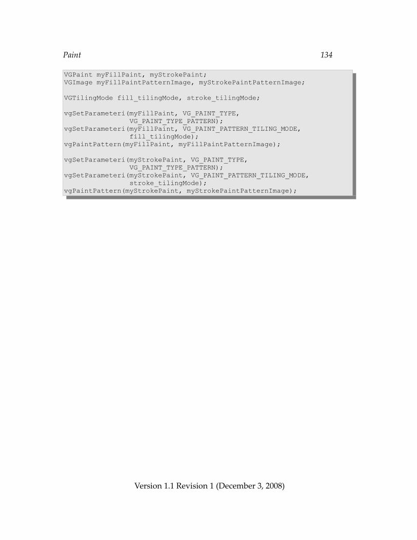
Paint 134
VGPaint myFillPaint, myStrokePaint;VGImage myFillPaintPatternImage, myStrokePaintPatternImage;
VGTilingMode fill_tilingMode, stroke_tilingMode;
vgSetParameteri(myFillPaint, VG_PAINT_TYPE, VG_PAINT_TYPE_PATTERN);vgSetParameteri(myFillPaint, VG_PAINT_PATTERN_TILING_MODE, fill_tilingMode);vgPaintPattern(myFillPaint, myFillPaintPatternImage);
vgSetParameteri(myStrokePaint, VG_PAINT_TYPE, VG_PAINT_TYPE_PATTERN);vgSetParameteri(myStrokePaint, VG_PAINT_PATTERN_TILING_MODE, stroke_tilingMode);vgPaintPattern(myStrokePaint, myStrokePaintPatternImage);
Version 1.1 Revision 1 (December 3, 2008)
Images 135
10 ImagesImages are rectangular collections of pixels. Image data may be inserted or extracted in a variety of formats with varying bit depths, color spaces, and alpha channel types. The actual storage format of an image is implementation-dependent, and may be optimized for a given device, but must allow pixels to be read and written losslessly. Images may be drawn to a drawing surface, used to define paint patterns, or operated on directly by image filter operations.
10.1 Image Coordinate SystemsAn image defines a coordinate system in which pixels are indexed using integer coordinates, with each integer corresponding to a distinct pixel. The lower-left pixel has a coordinate of (0, 0), the x coordinate increases horizontally from left to right, and the y coordinate increases vertically from bottom to top. Note that this orientation is consistent with the other coordinate systems used in the OpenVG API, but differs from the top-to-bottom orientation used by many other imaging systems.
The “energy” of a pixel is located at the pixel center; that is, the pixel with coordinate (x, y) has its energy at the point (x + ½, y + ½). The color at a point not located at a pixel center may be defined by applying a suitable filter to the colors defined at a set of nearby pixel centers.
10.2 Image Formats
VGImageFormatThe VGImageFormat enumeration defines the set of supported pixel formats and color spaces for images:
Version 1.1 Revision 1 (December 3, 2008)
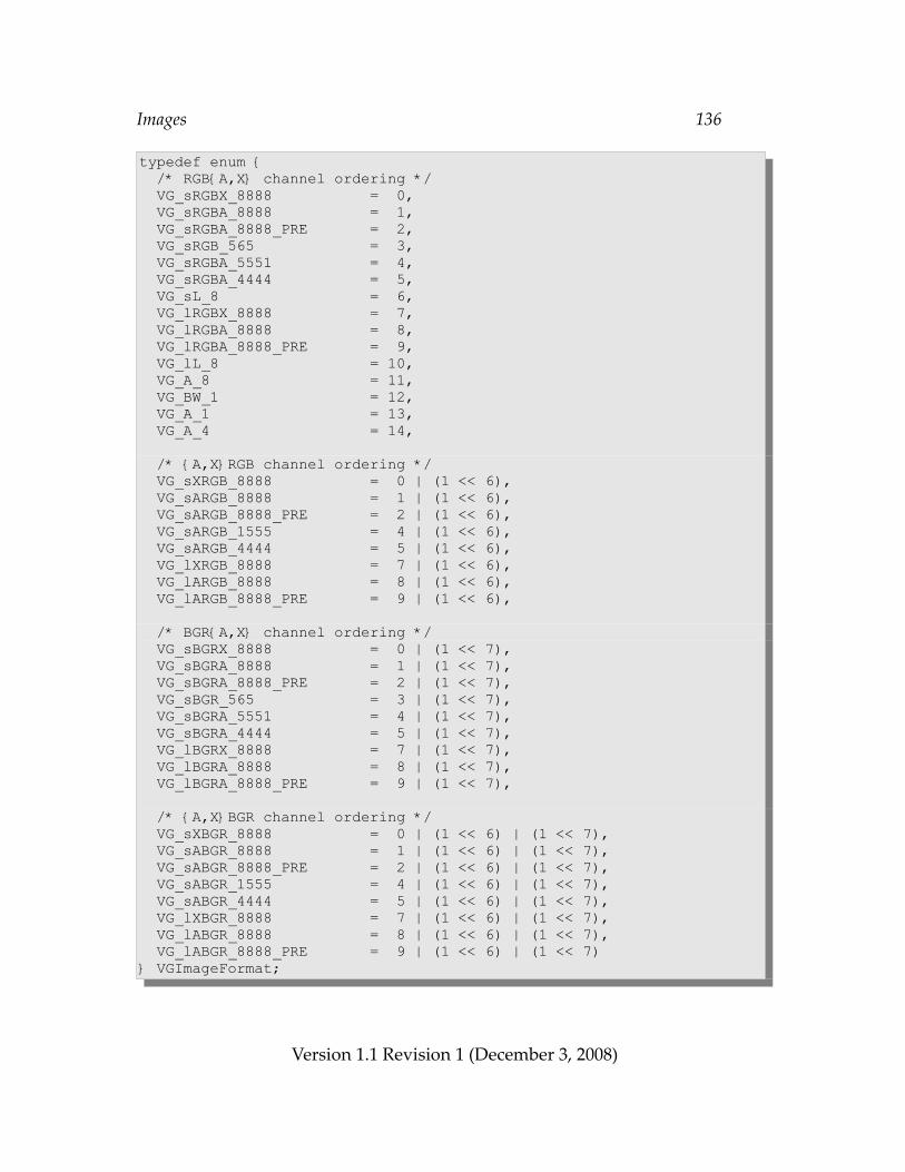
Images 136
typedef enum { /* RGB{A,X} channel ordering */ VG_sRGBX_8888 = 0, VG_sRGBA_8888 = 1, VG_sRGBA_8888_PRE = 2, VG_sRGB_565 = 3, VG_sRGBA_5551 = 4, VG_sRGBA_4444 = 5, VG_sL_8 = 6, VG_lRGBX_8888 = 7, VG_lRGBA_8888 = 8, VG_lRGBA_8888_PRE = 9, VG_lL_8 = 10, VG_A_8 = 11, VG_BW_1 = 12, VG_A_1 = 13, VG_A_4 = 14,
/* {A,X}RGB channel ordering */ VG_sXRGB_8888 = 0 | (1 << 6), VG_sARGB_8888 = 1 | (1 << 6), VG_sARGB_8888_PRE = 2 | (1 << 6), VG_sARGB_1555 = 4 | (1 << 6), VG_sARGB_4444 = 5 | (1 << 6), VG_lXRGB_8888 = 7 | (1 << 6), VG_lARGB_8888 = 8 | (1 << 6), VG_lARGB_8888_PRE = 9 | (1 << 6),
/* BGR{A,X} channel ordering */ VG_sBGRX_8888 = 0 | (1 << 7), VG_sBGRA_8888 = 1 | (1 << 7), VG_sBGRA_8888_PRE = 2 | (1 << 7), VG_sBGR_565 = 3 | (1 << 7), VG_sBGRA_5551 = 4 | (1 << 7), VG_sBGRA_4444 = 5 | (1 << 7), VG_lBGRX_8888 = 7 | (1 << 7), VG_lBGRA_8888 = 8 | (1 << 7), VG_lBGRA_8888_PRE = 9 | (1 << 7),
/* {A,X}BGR channel ordering */ VG_sXBGR_8888 = 0 | (1 << 6) | (1 << 7), VG_sABGR_8888 = 1 | (1 << 6) | (1 << 7), VG_sABGR_8888_PRE = 2 | (1 << 6) | (1 << 7), VG_sABGR_1555 = 4 | (1 << 6) | (1 << 7), VG_sABGR_4444 = 5 | (1 << 6) | (1 << 7), VG_lXBGR_8888 = 7 | (1 << 6) | (1 << 7), VG_lABGR_8888 = 8 | (1 << 6) | (1 << 7), VG_lABGR_8888_PRE = 9 | (1 << 6) | (1 << 7)} VGImageFormat;
Version 1.1 Revision 1 (December 3, 2008)
Images 137
The letter A denotes an alpha (α) channel , R denotes red, G denotes green, and B denotes blue. X denotes a padding byte that is ignored. L denotes grayscale, and BW denotes (linear) bi-level grayscale (black-and-white), with 0 representing black and 1 representing white in either case. A lower-case letter s represents a non-linear, perceptually-uniform color space, as in sRGB and sL; a lower-case letter l represents a linear color space using the sRGB primaries. Formats with a suffix of _PRE store pixel values in premultiplied format.
Bit 6 of the numeric values of the enumeration indicates the position of the alpha channel (or unused byte for formats that do not include alpha). If bit 6 is disabled, the alpha or unused channel appears as the last channel, otherwise it appears as the first channel. Bit 7 indicates the ordering of the RGB color channels. If bit 7 is disabled, the color channels appear in RGB order, otherwise they appear in BGR order.
The VG_A_8 format is treated as though it were VG_lRGBA_8888, with R=G=B=1. Color information is discarded when placing an RGBA value into a VG_A_8 pixel.
Abbreviated names such as lL or sRGBA_PRE are used in this document where the exact number of bits per channel is not relevant, such as when pixel values are considered to have been remapped to a [0, 1] range. Such abbreviated names are not an official part of the API.
The bits for each color channel are stored within a machine word representing a single pixel from left to right (MSB to LSB) in the order indicated by the pixel format name. For example, in a pixel with a format of VG_sRGB_565, the bits representing the red channel may be obtained by shifting right by 11 bits (to remove 6 bits of green and 5 bits of blue) and masking with the 5-bit wide mask value 0x1f. Note that this definition is independent of the endianness of the underlying platform as sub-word memory addresses are not involved.
Table 11 summarizes the symbols used in image format names.
Table 12 lists the size of a single pixel for each image format, in terms of bytes and bits. Note that all formats other than VG_BW_1, VG_A_1, and VG_A_4 use a whole number of bytes per pixel.
Formats having linear-light coding (VG_lRGBX_8888, VG_lRGBA_8888, VG_lRGBA_8888_PRE, and VG_lL8) are liable to exhibit banding (or contouring) artifacts when viewed with a contrast ratio greater than about 10:1 [POYN03] and are intended mainly for inputting existing linearly-coded imagery. For high-quality imaging, consider using one of the non-linear, perceptually uniform image formats such as VG_sRGBX_8888, VG_sRGBA_8888, VG_sRGBA_8888_PRE, and VG_sL_8.
Version 1.1 Revision 1 (December 3, 2008)
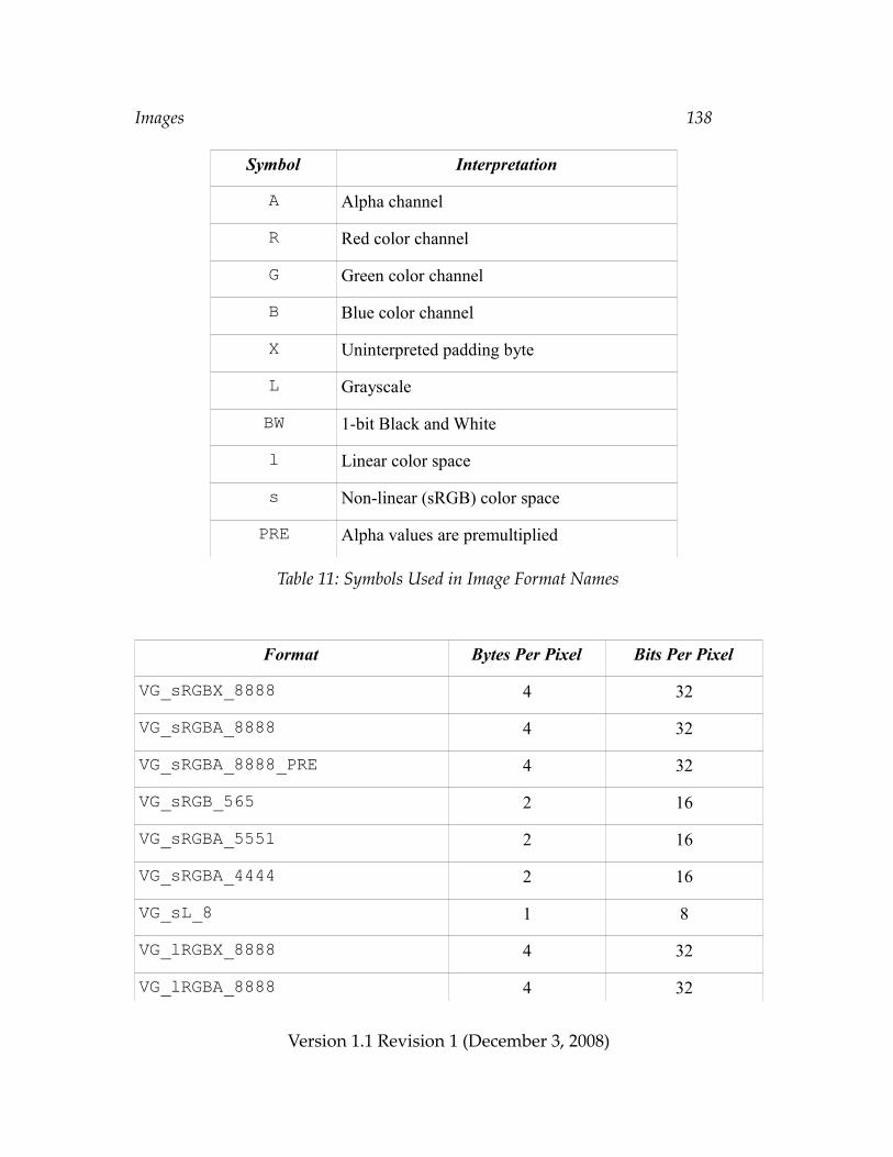
Images 138
Symbol Interpretation
A Alpha channel
R Red color channel
G Green color channel
B Blue color channel
X Uninterpreted padding byte
L Grayscale
BW 1-bit Black and White
l Linear color space
s Non-linear (sRGB) color space
PRE Alpha values are premultiplied
Table 11: Symbols Used in Image Format Names
Format Bytes Per Pixel Bits Per Pixel
VG_sRGBX_8888 4 32
VG_sRGBA_8888 4 32
VG_sRGBA_8888_PRE 4 32
VG_sRGB_565 2 16
VG_sRGBA_5551 2 16
VG_sRGBA_4444 2 16
VG_sL_8 1 8
VG_lRGBX_8888 4 32
VG_lRGBA_8888 4 32
Version 1.1 Revision 1 (December 3, 2008)
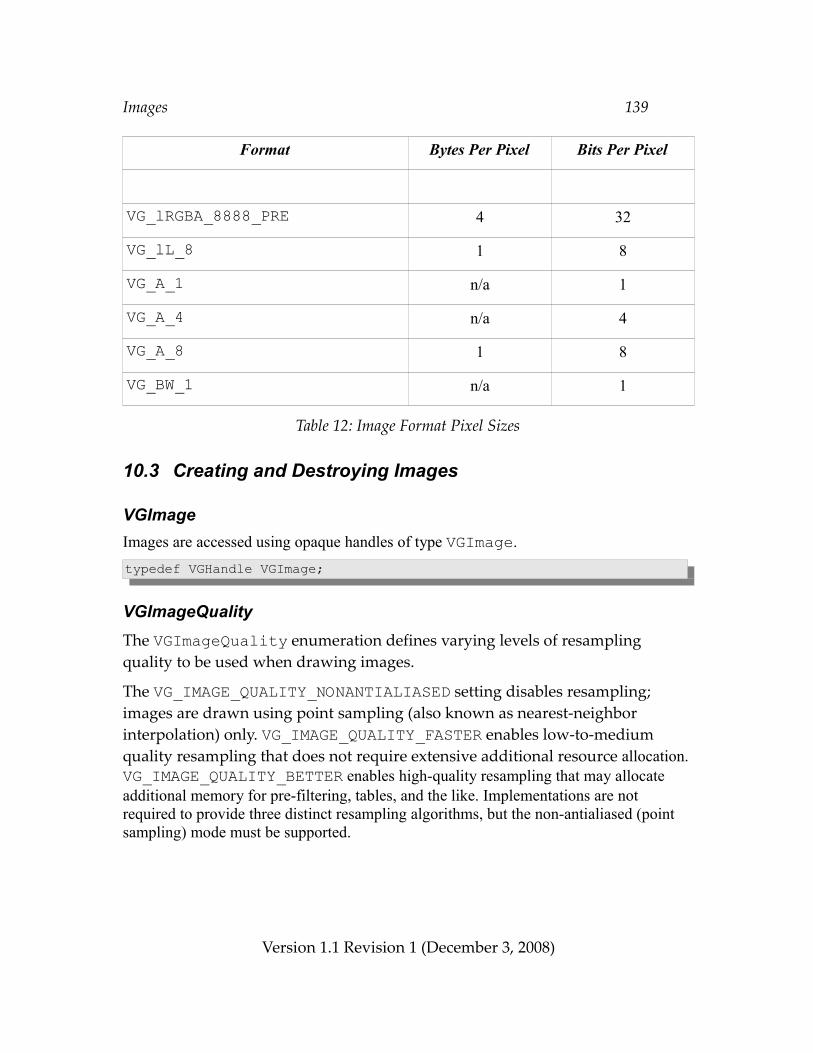
Images 139
Format Bytes Per Pixel Bits Per Pixel
VG_lRGBA_8888_PRE 4 32
VG_lL_8 1 8
VG_A_1 n/a 1
VG_A_4 n/a 4
VG_A_8 1 8
VG_BW_1 n/a 1
Table 12: Image Format Pixel Sizes
10.3 Creating and Destroying Images
VGImageImages are accessed using opaque handles of type VGImage.typedef VGHandle VGImage;
VGImageQualityThe VGImageQuality enumeration defines varying levels of resampling quality to be used when drawing images.
The VG_IMAGE_QUALITY_NONANTIALIASED setting disables resampling; images are drawn using point sampling (also known as nearest-neighbor interpolation) only. VG_IMAGE_QUALITY_FASTER enables low-to-medium quality resampling that does not require extensive additional resource allocation. VG_IMAGE_QUALITY_BETTER enables high-quality resampling that may allocate additional memory for pre-filtering, tables, and the like. Implementations are not required to provide three distinct resampling algorithms, but the non-antialiased (point sampling) mode must be supported.
Version 1.1 Revision 1 (December 3, 2008)
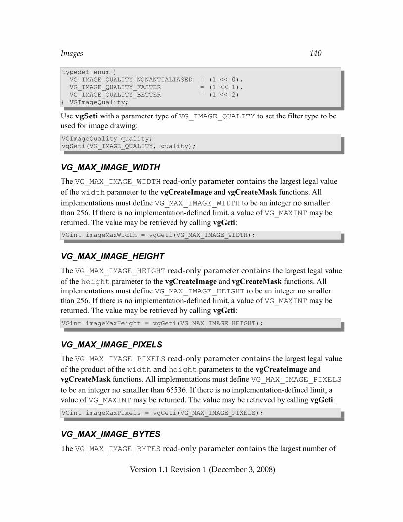
Images 140
typedef enum { VG_IMAGE_QUALITY_NONANTIALIASED = (1 << 0), VG_IMAGE_QUALITY_FASTER = (1 << 1), VG_IMAGE_QUALITY_BETTER = (1 << 2)} VGImageQuality;
Use vgSeti with a parameter type of VG_IMAGE_QUALITY to set the filter type to be used for image drawing:VGImageQuality quality;vgSeti(VG_IMAGE_QUALITY, quality);
VG_MAX_IMAGE_WIDTHThe VG_MAX_IMAGE_WIDTH read-only parameter contains the largest legal value of the width parameter to the vgCreateImage and vgCreateMask functions. All implementations must define VG_MAX_IMAGE_WIDTH to be an integer no smaller than 256. If there is no implementation-defined limit, a value of VG_MAXINT may be returned. The value may be retrieved by calling vgGeti:VGint imageMaxWidth = vgGeti(VG_MAX_IMAGE_WIDTH);
VG_MAX_IMAGE_HEIGHTThe VG_MAX_IMAGE_HEIGHT read-only parameter contains the largest legal value of the height parameter to the vgCreateImage and vgCreateMask functions. All implementations must define VG_MAX_IMAGE_HEIGHT to be an integer no smaller than 256. If there is no implementation-defined limit, a value of VG_MAXINT may be returned. The value may be retrieved by calling vgGeti:VGint imageMaxHeight = vgGeti(VG_MAX_IMAGE_HEIGHT);
VG_MAX_IMAGE_PIXELSThe VG_MAX_IMAGE_PIXELS read-only parameter contains the largest legal value of the product of the width and height parameters to the vgCreateImage and vgCreateMask functions. All implementations must define VG_MAX_IMAGE_PIXELS to be an integer no smaller than 65536. If there is no implementation-defined limit, a value of VG_MAXINT may be returned. The value may be retrieved by calling vgGeti:VGint imageMaxPixels = vgGeti(VG_MAX_IMAGE_PIXELS);
VG_MAX_IMAGE_BYTESThe VG_MAX_IMAGE_BYTES read-only parameter contains the largest number of
Version 1.1 Revision 1 (December 3, 2008)
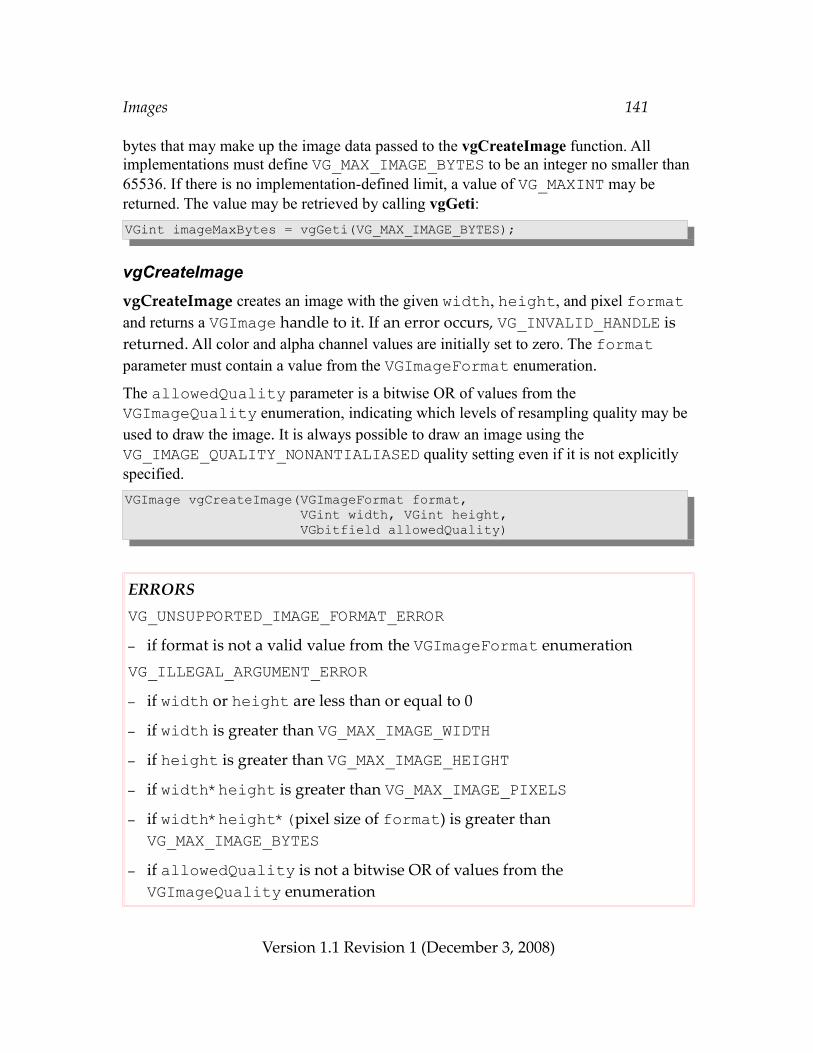
Images 141
bytes that may make up the image data passed to the vgCreateImage function. All implementations must define VG_MAX_IMAGE_BYTES to be an integer no smaller than 65536. If there is no implementation-defined limit, a value of VG_MAXINT may be returned. The value may be retrieved by calling vgGeti:VGint imageMaxBytes = vgGeti(VG_MAX_IMAGE_BYTES);
vgCreateImagevgCreateImage creates an image with the given width, height, and pixel format and returns a VGImage handle to it. If an error occurs, VG_INVALID_HANDLE is returned. All color and alpha channel values are initially set to zero. The format parameter must contain a value from the VGImageFormat enumeration.
The allowedQuality parameter is a bitwise OR of values from the VGImageQuality enumeration, indicating which levels of resampling quality may be used to draw the image. It is always possible to draw an image using the VG_IMAGE_QUALITY_NONANTIALIASED quality setting even if it is not explicitly specified.VGImage vgCreateImage(VGImageFormat format, VGint width, VGint height, VGbitfield allowedQuality)
ERRORSVG_UNSUPPORTED_IMAGE_FORMAT_ERROR– if format is not a valid value from the VGImageFormat enumerationVG_ILLEGAL_ARGUMENT_ERROR– if width or height are less than or equal to 0
– if width is greater than VG_MAX_IMAGE_WIDTH– if height is greater than VG_MAX_IMAGE_HEIGHT– if width*height is greater than VG_MAX_IMAGE_PIXELS– if width*height*(pixel size of format) is greater than VG_MAX_IMAGE_BYTES
– if allowedQuality is not a bitwise OR of values from the VGImageQuality enumeration
Version 1.1 Revision 1 (December 3, 2008)
Images 142
vgDestroyImageThe resources associated with an image may be deallocated by calling vgDestroyImage. Following the call, the image handle is no longer valid in any context that shared it. If the image is currently in use as a rendering target, is the ancestor of another image (see vgChildImage), is set as a paint pattern image on a VGPaint object, or is set as a glyph an a VGFont object, its definition remains available to those consumers as long as they remain valid, but the handle may no longer be used. When those uses cease, the image’s resources will automatically be deallocated.void vgDestroyImage(VGImage image);
ERRORSVG_BAD_HANDLE_ERROR– if image is not a valid image handle, or is not shared with the current
context
10.4 Querying Images
VGImageParamTypeValues from the VGImageParamType enumeration may be used as the paramType argument to vgGetParameter to query various features of an image. All of the parameters defined by VGImageParamType have integer values and are read-only.typedef enum { VG_IMAGE_FORMAT = 0x1E00, VG_IMAGE_WIDTH = 0x1E01, VG_IMAGE_HEIGHT = 0x1E02} VGImageParamType;
Image FormatThe value of the format parameter that was used to define the image may be queried using the VG_IMAGE_FORMAT parameter. The returned integral value should be cast to the VGImageFormat enumeration:
Version 1.1 Revision 1 (December 3, 2008)
Images 143
VGImage image;VGImageFormat imageFormat = (VGImageFormat)vgGetParameteri(image, VG_IMAGE_FORMAT);
Image WidthThe value of the width parameter that was used to define the image may be queried using the VG_IMAGE_WIDTH parameter:VGImage image;VGint imageWidth = vgGetParameteri(image, VG_IMAGE_WIDTH);
Image HeightThe value of the height parameter that was used to define the image may be queried using the VG_IMAGE_HEIGHT parameter:VGImage image;VGint imageHeight = vgGetParameteri(image, VG_IMAGE_HEIGHT);
10.5 Reading and Writing Image Pixels
vgClearImageThe vgClearImage function fills a given rectangle of an image with the color specified by the VG_CLEAR_COLOR parameter. The rectangle to be cleared is given by x, y, width, and height, which must define a positive region. The rectangle is clipped to the bounds of the image.void vgClearImage(VGImage image, VGint x, VGint y, VGint width, VGint height)
Version 1.1 Revision 1 (December 3, 2008)
Images 144
ERRORSVG_BAD_HANDLE_ERROR– if image is not a valid image handle, or is not shared with the current
contextVG_IMAGE_IN_USE_ERROR– if image is currently a rendering targetVG_ILLEGAL_ARGUMENT_ERROR– if width or height is less than or equal to 0
vgImageSubDataThe vgImageSubData function reads pixel values from memory, performs format conversion if necessary, and stores the resulting pixels into a rectangular portion of an image.
Pixel values are read starting at the address given by the pointer data; adjacent scanlines are separated by dataStride bytes. Negative or zero values of dataStride are allowed. The region to be written is given by x, y, width, and height, which must define a positive region. Pixels that fall outside the bounds of the image are ignored.
Pixel values in memory are formatted according to the dataFormat parameter, which must contain a value from the VGImageFormat enumeration. The data pointer must be aligned according to the number of bytes of the pixel format specified by dataFormat, unless dataFormat is equal to VG_BW_1, VG_A_1, or VG_A_4, in which case 1 byte alignment is sufficient. Each pixel is converted into the format of the destination image as it is written.
If dataFormat is not equal to VG_BW_1, VG_A_1, or VG_A_4, the destination image pixel (x + i, y + j) for 0 ≤ i < width and 0 ≤ j < height is taken from the N bytes of memory starting at data + j*dataStride + i*N, where N is the number of bytes per pixel given in Table 12. For multi-byte pixels, the bits are arranged in the same order used to store native multi-byte primitive datatypes. For example, a 16-bit pixel would be written to memory in the same format as when writing through a pointer with a native 16-bit integral datatype.
If dataFormat is equal to VG_BW_1 or VG_A_1, pixel (x + i, y + j) of the destination image is taken from the bit at position (i % 8) within the byte at data +
Version 1.1 Revision 1 (December 3, 2008)
Images 145
j*dataStride + floor(i/8) where the least significant bit (LSB) of a byte is considered to be at position 0 and the most significant bit (MSB) is at position 7. Each scanline must be padded to a multiple of 8 bits. Note that dataStride is always given in terms of bytes, not bits.
If dataFormat is equal to VG_A_4, pixel (x + i, y + j) of the destination image is taken from the 4 bits from position (4*(i % 2)) to (4*(i % 2) + 3) within the byte at data + j*dataStride + floor(i/2). Each scanline must be padded to a multiple of 8 bits.
If dataFormat specifies a premultiplied format (VG_sRGBA_8888_PRE or VG_lRGBA_8888_PRE), color channel values of a pixel greater than their corresponding alpha value are clamped to the range [0, alpha].void vgImageSubData(VGImage image, const void * data, VGint dataStride, VGImageFormat dataFormat, VGint x, VGint y, VGint width, VGint height)
ERRORSVG_BAD_HANDLE_ERROR– if image is not a valid image handle, or is not shared with the current
contextVG_IMAGE_IN_USE_ERROR– if image is currently a rendering targetVG_UNSUPPORTED_IMAGE_FORMAT_ERROR– if dataFormat is not a valid value from the VGImageFormat enumerationVG_ILLEGAL_ARGUMENT_ERROR– if width or height is less than or equal to 0
– if data is NULL– if data is not properly aligned
vgGetImageSubDataThe vgGetImageSubData function reads pixel values from a rectangular portion of an image, performs format conversion if necessary, and stores the resulting pixels into memory.
Version 1.1 Revision 1 (December 3, 2008)
Images 146
Pixel values are written starting at the address given by the pointer data; adjacent scanlines are separated by dataStride bytes. Negative or zero values of dataStride are allowed. The region to be read is given by x, y, width, and height, which must define a positive region. Pixels that fall outside the bounds of the image are ignored.
Pixel values in memory are formatted according to the dataFormat parameter, which must contain a value from the VGImageFormat enumeration. If dataFormat specifies a premultiplied format (VG_sRGBA_8888_PRE or VG_lRGBA_8888_PRE), color channel values of a pixel that are greater than their corresponding alpha value are clamped to the range [0, alpha]. The data pointer alignment and the pixel layout in memory are as described in the vgImageSubData section.void vgGetImageSubData(VGImage image, void * data, VGint dataStride, VGImageFormat dataFormat, VGint x, VGint y, VGint width, VGint height)
ERRORSVG_BAD_HANDLE_ERROR– if image is not a valid image handle, or is not shared with the current contextVG_IMAGE_IN_USE_ERROR– if image is currently a rendering targetVG_UNSUPPORTED_IMAGE_FORMAT_ERROR– if dataFormat is not a valid value from the VGImageFormat enumerationVG_ILLEGAL_ARGUMENT_ERROR– if width or height is less than or equal to 0
– if data is NULL
– if data is not properly aligned
10.6 Child ImagesA child image is an image that shares physical storage with a portion of an existing image, known as its parent. An image may have any number of children, but each image has only one parent (that may be itself). An ancestor of an image is defined as the image itself, its parent, its parent’s parent, etc. By definition, a pair of images are said to be
Version 1.1 Revision 1 (December 3, 2008)
Images 147
related if and only if they have a common ancestor. Specifically, two images that are children of a common parent are considered to be related even if their respective pixel areas within the parent do not overlap. Changes to an image are immediately reflected in all other images to which it is related.
A child image remains valid even following a call to vgDestroyImage on one of its ancestors (other than itself). When the last image of a set of related images is destroyed, the entire storage will be reclaimed. Implementations may use a reference count to determine when image storage may be reclaimed.
A child image may not be used as a rendering target. A parent image may not be used as a rendering target until all the child images derived from it have been destroyed.
vgChildImageThe vgChildImage function returns a new VGImage handle that refers to a portion of the parent image. The region is given by the intersection of the bounds of the parent image with the rectangle beginning at pixel (x, y) with dimensions width and height, which must define a positive region contained entirely within parent.VGImage vgChildImage(VGImage parent, VGint x, VGint y, VGint width, VGint height)
ERRORSVG_BAD_HANDLE_ERROR– if parent is not a valid image handle, or is not shared with the current
contextVG_IMAGE_IN_USE_ERROR– if parent is currently a rendering targetVG_ILLEGAL_ARGUMENT_ERROR– if x is less than 0 or greater than or equal to the parent width
– if y is less than 0 or greater than or equal to the parent height
– if width or height is less than or equal to 0
– if x + width is greater than the parent width
– if y + height is greater than the parent height
Version 1.1 Revision 1 (December 3, 2008)
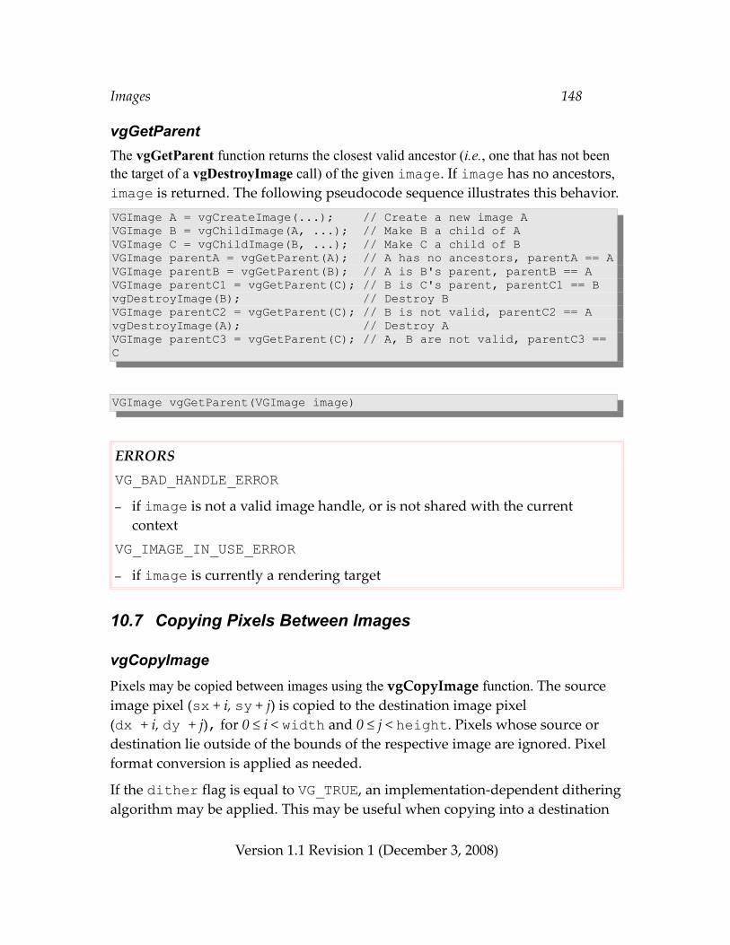
Images 148
vgGetParentThe vgGetParent function returns the closest valid ancestor (i.e., one that has not been the target of a vgDestroyImage call) of the given image. If image has no ancestors, image is returned. The following pseudocode sequence illustrates this behavior.VGImage A = vgCreateImage(...); // Create a new image AVGImage B = vgChildImage(A, ...); // Make B a child of AVGImage C = vgChildImage(B, ...); // Make C a child of BVGImage parentA = vgGetParent(A); // A has no ancestors, parentA == AVGImage parentB = vgGetParent(B); // A is B's parent, parentB == AVGImage parentC1 = vgGetParent(C); // B is C's parent, parentC1 == BvgDestroyImage(B); // Destroy BVGImage parentC2 = vgGetParent(C); // B is not valid, parentC2 == AvgDestroyImage(A); // Destroy AVGImage parentC3 = vgGetParent(C); // A, B are not valid, parentC3 == C
VGImage vgGetParent(VGImage image)
ERRORSVG_BAD_HANDLE_ERROR– if image is not a valid image handle, or is not shared with the current
contextVG_IMAGE_IN_USE_ERROR– if image is currently a rendering target
10.7 Copying Pixels Between Images
vgCopyImagePixels may be copied between images using the vgCopyImage function. The source image pixel (sx + i, sy + j) is copied to the destination image pixel (dx + i, dy + j), for 0 ≤ i < width and 0 ≤ j < height. Pixels whose source or destination lie outside of the bounds of the respective image are ignored. Pixel format conversion is applied as needed.
If the dither flag is equal to VG_TRUE, an implementation-dependent dithering algorithm may be applied. This may be useful when copying into a destination
Version 1.1 Revision 1 (December 3, 2008)
Images 149
image with a smaller color bit depth than that of the source image. Implementations should choose an algorithm that will provide good results when the output images are displayed as successive frames in an animation.
If src and dst are the same image, or are related, the copy will occur in a consistent fashion as though the source pixels were first copied into a temporary buffer and then copied from the temporary buffer to the destination.void vgCopyImage(VGImage dst, VGint dx, VGint dy, VGImage src, VGint sx, VGint sy, VGint width, VGint height, VGboolean dither)
ERRORSVG_BAD_HANDLE_ERROR– if either dst or src is not a valid image handle, or is not shared with the
current contextVG_IMAGE_IN_USE_ERROR– if either dst or src is currently a rendering targetVG_ILLEGAL_ARGUMENT_ERROR– if width or height is less than or equal to 0
10.8 Drawing Images to the Drawing SurfaceImages may be drawn onto a drawing surface. An affine or projective transformation may be applied while drawing. The current image and blending modes are used to control how image pixels are combined with the current paint and blended into the destination. Conversion between the image and destination pixel formats is applied automatically.
VGImageModeThe VGImageMode enumeration is used to select between several styles of image drawing, described in the vgDrawImage section below.
Version 1.1 Revision 1 (December 3, 2008)
Images 150
typedef enum { VG_DRAW_IMAGE_NORMAL = 0x1F00, VG_DRAW_IMAGE_MULTIPLY = 0x1F01, VG_DRAW_IMAGE_STENCIL = 0x1F02} VGImageMode;
To set the mode, use vgSeti with a paramType value of VG_IMAGE_MODE:VGImageMode drawImageMode;vgSeti(VG_IMAGE_MODE, drawImageMode);
vgDrawImageAn image may be drawn to the current drawing surface using the vgDrawImage function. The current image-user-to-surface transformation Ti is applied to the image, so that the image pixel centered at (px + ½, py + ½) is mapped to the point (Ti)(px + ½, py + ½). In practice, backwards mapping may be used. That is, a sample located at (x, y) in the surface coordinate system is colored according to an interpolated image pixel value at the point (Ti)-1(x, y) in the image coordinate system. If Ti is non-invertible (or nearly so, within the limits of numerical accuracy), no drawing occurs.
Interpolation is done in the color space of the image. Image color values are processed in premultiplied alpha format during interpolation. Color channel values are clamped to the range [0, alpha] before interpolation.
When a projective transformation is used (i.e., the bottom row of the image-user-to-surface transformation contains values [ w0 w1 w2 ] different from [ 0 0 1 ]), each corner point (x, y) of the image must result in a positive value of d = (x*w0 + y*w1 + w2), or else nothing is drawn. This rule prevents degeneracies due to transformed image points passing through infinity, which occurs when d passes through 0. By requiring d to be positive at the corners, it is guaranteed to be positive at all interior points as well.
When a projective transformation is used, the value of the VG_IMAGE_MODE parameter is ignored and the behavior of VG_DRAW_IMAGE_NORMAL is substituted. This avoids the need to generate paint pixels in perspective.
The set of pixels affected consists of the quadrilateral with vertices (Ti)(0, 0), (Ti)(w, 0), (Ti)(w, h), and (Ti)(0, h) (where w and h are respectively the width and height of the image), plus a boundary of up to 1½ pixels for filtering purposes.
Clipping, masking, and scissoring are applied in the same manner as with vgDrawPath. To limit drawing to a subregion of the image, create a child image using vgChildImage.
The image quality will be the maximum quality allowed by the image (as determined by the allowedQuality parameter to vgCreateImage) that is not higher than the current
Version 1.1 Revision 1 (December 3, 2008)
Images 151
setting of VG_IMAGE_QUALITY.void vgDrawImage(VGImage image)
ERRORSVG_BAD_HANDLE_ERROR– if image is not a valid image handle, or is not shared with the current
contextVG_IMAGE_IN_USE_ERROR– if image is currently a rendering target
The effects of vgDrawImage depend on the current setting of the VG_IMAGE_MODE parameter:
VG_DRAW_IMAGE_NORMALWhen the VG_IMAGE_MODE parameter is set to VG_DRAW_IMAGE_NORMAL, the image is drawn. If the image contains an alpha channel, the alpha values associated with each pixel are used as the source alpha values. Otherwise, the source alpha is taken to be 1 at each pixel. No paint generation takes place. When a projective transformation is used, this mode is used regardless of the setting of the VG_IMAGE_MODE parameter.
VG_DRAW_IMAGE_MULTIPLYWhen the VG_IMAGE_MODE parameter is set to VG_DRAW_IMAGE_MULTIPLY, the image being drawn is multiplied by the paint color and alpha values. This allows the image to be drawn translucently (by setting the paint color to R=G=B=1 and A=opacity), or to be modulated in other ways. For example, a gradient paint could be used to create a fading effect, or a pattern paint could be used to vary the opacity on a pixel-by-pixel basis. If the paint color is opaque white (R=G=B=A=1) everywhere, the results are equivalent to those of VG_DRAW_IMAGE_NORMAL.
Paint generation (using the VGPaint object defined for the VG_FILL_PATH paint mode) occurs at each pixel, and the interpolated image and paint color and alpha values are multiplied channel-by-channel. The result (considered to be in the same color space as the image) is used as the input to the color transform stage, the output of which is used as the input to the current blend function, and normal blending takes place. Luminance formats are expanded to RGB using formula (4) of section 3.4.2.
Note that the use of a source image having a linear pixel format (e.g., lRGB_888) will
Version 1.1 Revision 1 (December 3, 2008)
Images 152
result in a brightened output due to the fact that the paint values are not converted from sRGB to linear, yet the results are treated as linear. Therefore the use of a linear source image in this mode is recommended only for special effects.
VG_DRAW_IMAGE_STENCILWhen the VG_IMAGE_MODE parameter is set to VG_DRAW_IMAGE_STENCIL, the image being drawn acts as a stencil through which the current paint is applied. This allows an image to take the place of a geometric path definition in some cases, such as drawing text glyphs. A special set of blending equations allows the red, green, and blue channels to be blended using distinct alpha values taken from the image. This feature allows stencils to take advantage of sub-pixel effects on LCD displays.
Paint generation (using the VGPaint object defined for the VG_FILL_PATH paint mode) occurs at each pixel. The interpolated image and paint color and alpha values are combined at each pixel as follows. Each image color channel value is multiplied by its corresponding alpha value (if the image has an alpha channel) and by the paint alpha value to produce an alpha value associated with that color channel. The current blending equation (see Section 13) is applied separately for each destination color channel, using the alpha value computed above as the source alpha value for the blend; the paint color value is used as input to the color transform stage, the output of which is used as the source color value for blending.
In terms of the blending functions α(αsrc, αdst) and c(csrc, cdst, αsrc, αdst) defined in Section 13.2, the stenciled output color and alpha values for an RGB destination are:
αtmp = α(αimage*αpaint, αdst)
Rdst ← c(Rpaint, Rdst, Rimage*αimage*αpaint, αdst) / αtmp
Gdst ← c(Gpaint, Gdst, Gimage*αimage*αpaint, αdst) / αtmp
Bdst ← c(Bpaint, Bdst, Bimage*αimage*αpaint, αdst) / αtmp
αdst ← αtmp
For example, if Porter-Duff “Src over Dst” blending is enabled (see Section 13.3), the destination alpha and color values are computed as:
αtmp = (αimage*αpaint + αdst*(1 – αimage*αpaint))
Rdst ← (αimage*αpaint *Rimage*Rpaint + αdst*Rdst*(1 – αimage*αpaint *Rimage)) / αtmp
Gdst ← (αimage*αpaint *Gimage*Gpaint + αdst*Gdst*(1 – αimage*αpaint *Gimage)) / αtmp
Version 1.1 Revision 1 (December 3, 2008)
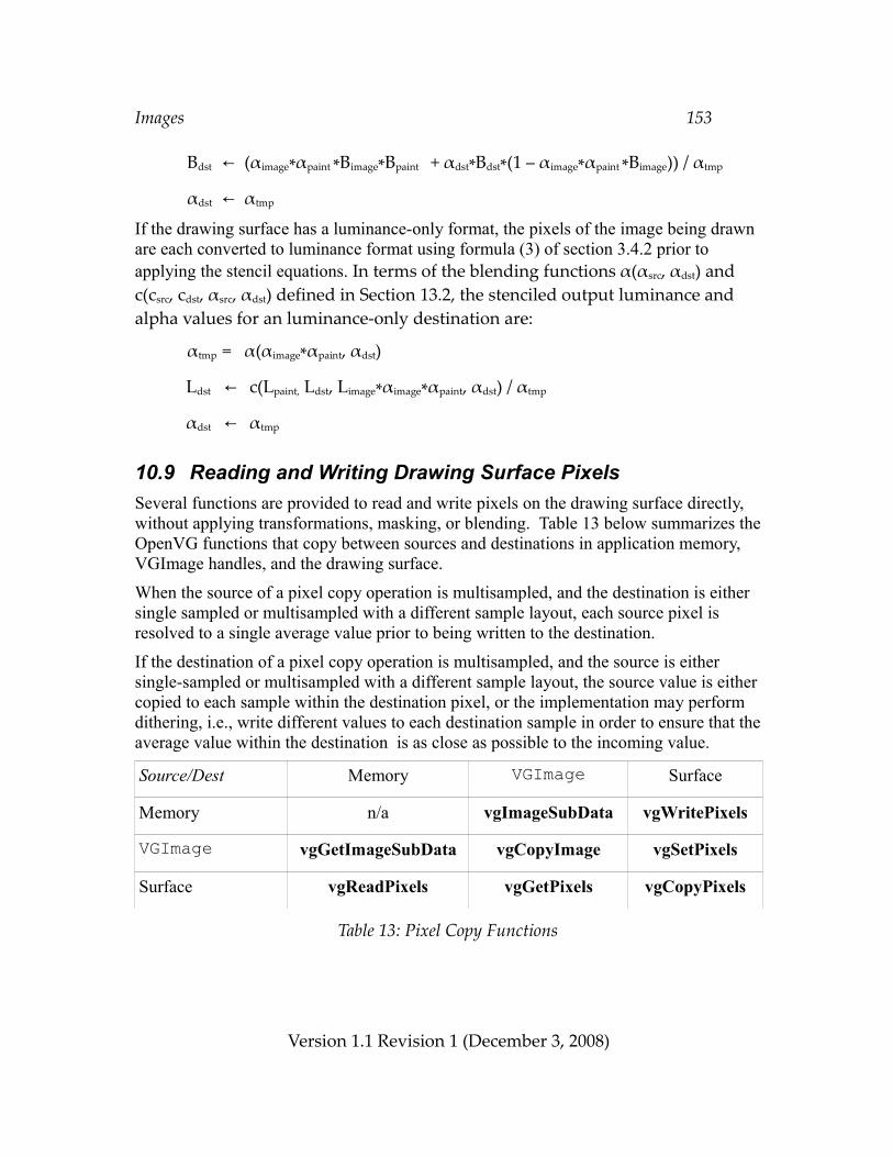
Images 153
Bdst ← (αimage*αpaint *Bimage*Bpaint + αdst*Bdst*(1 – αimage*αpaint *Bimage)) / αtmp
αdst ← αtmp
If the drawing surface has a luminance-only format, the pixels of the image being drawn are each converted to luminance format using formula (3) of section 3.4.2 prior to applying the stencil equations. In terms of the blending functions α(αsrc, αdst) and c(csrc, cdst, αsrc, αdst) defined in Section 13.2, the stenciled output luminance and alpha values for an luminance-only destination are:
αtmp = α(αimage*αpaint, αdst)
Ldst ← c(Lpaint, Ldst, Limage*αimage*αpaint, αdst) / αtmp
αdst ← αtmp
10.9 Reading and Writing Drawing Surface PixelsSeveral functions are provided to read and write pixels on the drawing surface directly, without applying transformations, masking, or blending. Table 13 below summarizes the OpenVG functions that copy between sources and destinations in application memory, VGImage handles, and the drawing surface.
When the source of a pixel copy operation is multisampled, and the destination is either single sampled or multisampled with a different sample layout, each source pixel is resolved to a single average value prior to being written to the destination.
If the destination of a pixel copy operation is multisampled, and the source is either single-sampled or multisampled with a different sample layout, the source value is either copied to each sample within the destination pixel, or the implementation may perform dithering, i.e., write different values to each destination sample in order to ensure that the average value within the destination is as close as possible to the incoming value.
Source/Dest Memory VGImage Surface
Memory n/a vgImageSubData vgWritePixels
VGImage vgGetImageSubData vgCopyImage vgSetPixels
Surface vgReadPixels vgGetPixels vgCopyPixels
Table 13: Pixel Copy Functions
Version 1.1 Revision 1 (December 3, 2008)
Images 154
10.9.1 Writing Drawing Surface Pixels
vgSetPixelsThe vgSetPixels function copies pixel data from the image src onto the drawing surface. The image pixel (sx + i, sy + j) is copied to the drawing surface pixel (dx + i, dy + j), for 0 ≤ i < width and 0 ≤ j < height. Pixels whose source lies outside of the bounds of src or whose destination lies outside the bounds of the drawing surface are ignored. Pixel format conversion is applied as needed. Scissoring takes place normally. Transformations, masking, and blending are not applied.void vgSetPixels(VGint dx, VGint dy, VGImage src, VGint sx, VGint sy, VGint width, VGint height)
ERRORSVG_BAD_HANDLE_ERROR– if src is not a valid image handle, or is not shared with the current contextVG_IMAGE_IN_USE_ERROR– if src is currently a rendering targetVG_ILLEGAL_ARGUMENT_ERROR– if width or height is less than or equal to 0
vgWritePixelsThe vgWritePixels function allows pixel data to be copied to the drawing surface without the creation of a VGImage object. The pixel values to be drawn are taken from the data pointer at the time of the vgWritePixels call, so future changes to the data have no effect. The effects of changes to the data by another thread at the time of the call to vgWritePixels are undefined.
The dataFormat parameter must contain a value from the VGImageFormat enumeration. The alignment and layout of pixels is the same as for vgImageSubData.
If dataFormat specifies a premultiplied format (VG_sRGBA_8888_PRE or VG_lRGBA_8888_PRE), color channel values of a pixel greater than their
Version 1.1 Revision 1 (December 3, 2008)
Images 155
corresponding alpha value are clamped to the range [0, alpha].
Pixels whose destination coordinate lies outside the bounds of the drawing surface are ignored. Pixel format conversion is applied as needed. Scissoring takes place normally. Transformations, masking, and blending are not applied.void vgWritePixels(const void * data, VGint dataStride, VGImageFormat dataFormat, VGint dx, VGint dy, VGint width, VGint height)
ERRORSVG_UNSUPPORTED_IMAGE_FORMAT_ERROR– if dataFormat is not a valid value from the VGImageFormat enumerationVG_ILLEGAL_ARGUMENT_ERROR– if width or height is less than or equal to 0
– if data is NULL– if data is not properly aligned
The code:void * data;VGImageFormat dataFormat;VGint dataStride;VGint dx, dy, width, height;
vgWritePixels(data, dataStride, dataFormat, dx, dy, width, height);is equivalent to the code:VGImage image;void * data;VGImageFormat dataFormat;VGint dataStride;VGint dx, dy, width, height;
image = vgCreateImage(dataFormat, width, height, 0);vgImageSubData(image, data, dataStride, dataFormat, 0, 0, width, height);vgSetPixels(dx, dy, image, width, height);vgDestroyImage(image);
Version 1.1 Revision 1 (December 3, 2008)
Images 156
10.9.2 Reading Drawing Surface Pixels
vgGetPixelsThe vgGetPixels function retrieves pixel data from the drawing surface into the image dst. The drawing surface pixel (sx + i, sy + j) is copied to pixel (dx + i, dy + j) of the image dst, for 0 ≤ i < width and 0 ≤ j < height. Pixels whose source lies outside of the bounds of the drawing surface or whose destination lies outside the bounds of dst are ignored. Pixel format conversion is applied as needed. The scissoring region does not affect the reading of pixels.void vgGetPixels(VGImage dst, VGint dx, VGint dy, VGint sx, VGint sy, VGint width, VGint height)
ERRORSVG_BAD_HANDLE_ERROR– if dst is not a valid image handle, or is not shared with the current contextVG_IMAGE_IN_USE_ERROR– if dst is currently a rendering targetVG_ILLEGAL_ARGUMENT_ERROR– if width or height is less than or equal to 0
vgReadPixelsThe vgReadPixels function allows pixel data to be copied from the drawing surface without the creation of a VGImage object.
Pixel values are written starting at the address given by the pointer data; adjacent scanlines are separated by dataStride bytes. Negative or zero values of dataStride are allowed. The region to be read is given by x, y, width, and height, which must define a positive region.
Pixel values in memory are formatted according to the dataFormat parameter, which must contain a value from the VGImageFormat enumeration. The data pointer alignment and the pixel layout in memory is as described in the vgImageSubData section.
Version 1.1 Revision 1 (December 3, 2008)
Images 157
Pixels whose source lies outside of the bounds of the drawing surface are ignored. Pixel format conversion is applied as needed. The scissoring region does not affect the reading of pixels.void vgReadPixels(void * data, VGint dataStride, VGImageFormat dataFormat, VGint sx, VGint sy, VGint width, VGint height)
ERRORSVG_UNSUPPORTED_IMAGE_FORMAT_ERROR– if dataFormat is not a valid value from the VGImageFormat enumerationVG_ILLEGAL_ARGUMENT_ERROR– if width or height is less than or equal to 0
– if data is NULL– if data is not properly aligned
Version 1.1 Revision 1 (December 3, 2008)
Images 158
The code:void * data;VGImageFormat dataFormat;VGint dataStride;VGint sx, sy, width, height;
vgReadPixels(data, dataStride, dataFormat, sx, sy, width, height);is equivalent to the following code, assuming the specified rectangle lies completely within the drawing surface bounds :VGImage image;void * data;VGint dataStride;VGImageFormat dataFormat;VGint sx, sy, width, height;
image = vgCreateImage(dataFormat, width, height, 0);vgGetPixels(image, 0, 0, sx, sy, width, height);vgGetImageSubData(image, data, dataStride, dataFormat, width, height);vgDestroyImage(image);
10.10 Copying Portions of the Drawing Surface
vgCopyPixelsThe vgCopyPixels function copies pixels from one region of the drawing surface to another. Copies between overlapping regions are allowed and always produce consistent results identical to copying the entire source region to a scratch buffer followed by copying the scratch buffer into the destination region.
The drawing surface pixel (sx + i, sy + j) is copied to pixel (dx + i, dy + j) for 0 ≤ i < width and 0 ≤ j < height. Pixels whose source or destination lies outside of the bounds of the drawing surface are ignored. Transformations, masking, and blending are not applied. Scissoring is applied to the destination, but does not affect the reading of pixels.void vgCopyPixels(VGint dx, VGint dy, VGint sx, VGint sy, VGint width, VGint height)
Version 1.1 Revision 1 (December 3, 2008)
Images 159
ERRORSVG_ILLEGAL_ARGUMENT_ERROR– if width or height is less than or equal to 0
Version 1.1 Revision 1 (December 3, 2008)
Text 160
11 TextSeveral classes of applications were considered in order to determining the set of features supported by the OpenVG text rendering API. E-book readers, scalable user interfaces with text-driven menus, and SVG viewers used to display text-intensive content rely on high-quality text rendering using well-hinted fonts. For these applications, the use of unhinted outlines, or the use of hardware-accelerated glyph scaling that does not support hints, would be detrimental to application rendering quality. Gaming applications that use special custom fonts, applications where text is rotated or placed along a path, or SVG viewers where unhinted SVG fonts are specified are less sensitive to the use of unhinted fonts for text rendering and may benefit from hardware-accelerated glyph scaling.
These application requirements made it clear that OpenVG must provide a fast, low-level hardware-accelerated API that is capable of supporting both hinted and unhinted vector glyph outlines, as well as glyphs represented as bitmaps.
11.1 Text RenderingThe process of text rendering involves the following steps:
• selection of a font, font style and size; • scaling of glyphs used in a text fragment, including hint processing;• composing the text on a page or within a text box;• rendering of glyph outlines into bitmap images; and• blitting of bitmap images to a frame buffer or a screen.
Font and glyph scaling is usually done once for each selected text size; however, the rendering of glyph outlines and blitting of bitmaps is repeated routinely. While caching of rendered bitmaps may improve performance of software rendering solutions, hardware acceleration of routine and repetitive tasks may significantly improve the overall performance of applications.
OpenVG provides a mechanism to allow applications to define a VGFont object as a collection of glyphs, where each glyph can be represented as either a VGPath representing either an original unhinted outline that can be scaled and rendered, or a scaled and hinted outline; or a VGImage representing a scaled, optionally hinted, and rendered image of a glyph. Use of a VGImage provides the opportunity to use hardware acceleration with bitmap fonts, or when a font size or rendering quality requirement cannot be satisfied by generic outline
Version 1.1 Revision 1 (December 3, 2008)
Text 161
rendering. No further hinting is applied to image glyphs.
OpenVG can assist applications in text composition by hardware-accelerating glyph positioning calculations; however, the text layout and positioning are the responsibilities of the application.
11.2 Font TerminologyIn typesetting literature, and throughout this chapter, the terms character and glyph are sometimes used interchangeably to refer to a single letter, number, punctuation mark, accent, or symbol in a string of text, or in a font or a typeface. In strict terms, the term “character” refers to a computer code representing the unit of text content (e.g., a symbol from a particular alphabet – a Latin character, Chinese character, etc.) while the term “glyph” refers to the unit of text display defining an image of a character or group of characters (ligature). Each character may be represented by many different glyphs from multiple typefaces having different styles. In complex scripts, a character can change its appearance depending on its position in a word and on adjacent characters, and can be associated with more than one glyph of the same font.
When fonts are scaled to a small size, there may not be enough pixels to display all the subtleties of the typeface design. Some features of the glyphs may be severely distorted, or may even completely disappear at small sizes. In order to make sure that the original design and legibility of a typeface is preserved, fonts typically contain additional data – a set of special instructions that are executed when a font is scaled to a particular size, known as hints. In TrueType and OpenType font formats, the hints are special byte-code instructions that are interpreted and executed by the rasterizer. Hints allow font developers to control the alignment of the outline data points with the pixel grid of the output device to ensure that glyph outlines are always rendered faithfully to the original design.
11.3 Glyph Positioning and Text LayoutScalable fonts define glyphs using vector outlines and additional set of data, such as hinting instructions, font and glyph metrics, etc. A typical glyph would be defined as presented in Figure 23 below:
Version 1.1 Revision 1 (December 3, 2008)
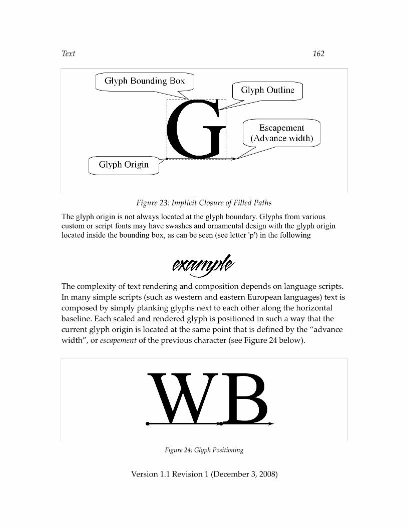
Text 162
Figure 23: Implicit Closure of Filled Paths
The glyph origin is not always located at the glyph boundary. Glyphs from various custom or script fonts may have swashes and ornamental design with the glyph origin located inside the bounding box, as can be seen (see letter 'p') in the following
The complexity of text rendering and composition depends on language scripts. In many simple scripts (such as western and eastern European languages) text is composed by simply planking glyphs next to each other along the horizontal baseline. Each scaled and rendered glyph is positioned in such a way that the current glyph origin is located at the same point that is defined by the “advance width”, or escapement of the previous character (see Figure 24 below).
Figure 24: Glyph Positioning
Version 1.1 Revision 1 (December 3, 2008)
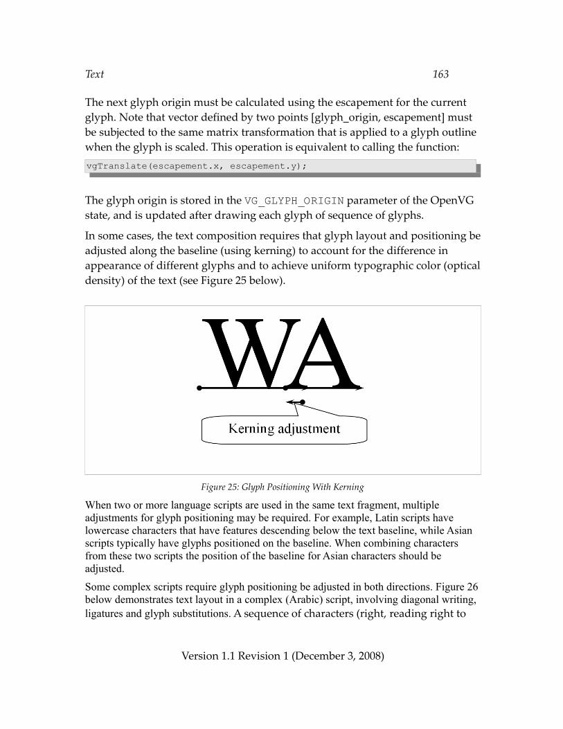
Text 163
The next glyph origin must be calculated using the escapement for the current glyph. Note that vector defined by two points [glyph_origin, escapement] must be subjected to the same matrix transformation that is applied to a glyph outline when the glyph is scaled. This operation is equivalent to calling the function: vgTranslate(escapement.x, escapement.y);
The glyph origin is stored in the VG_GLYPH_ORIGIN parameter of the OpenVG state, and is updated after drawing each glyph of sequence of glyphs.
In some cases, the text composition requires that glyph layout and positioning be adjusted along the baseline (using kerning) to account for the difference in appearance of different glyphs and to achieve uniform typographic color (optical density) of the text (see Figure 25 below).
Figure 25: Glyph Positioning With Kerning
When two or more language scripts are used in the same text fragment, multiple adjustments for glyph positioning may be required. For example, Latin scripts have lowercase characters that have features descending below the text baseline, while Asian scripts typically have glyphs positioned on the baseline. When combining characters from these two scripts the position of the baseline for Asian characters should be adjusted.
Some complex scripts require glyph positioning be adjusted in both directions. Figure 26 below demonstrates text layout in a complex (Arabic) script, involving diagonal writing, ligatures and glyph substitutions. A sequence of characters (right, reading right to
Version 1.1 Revision 1 (December 3, 2008)
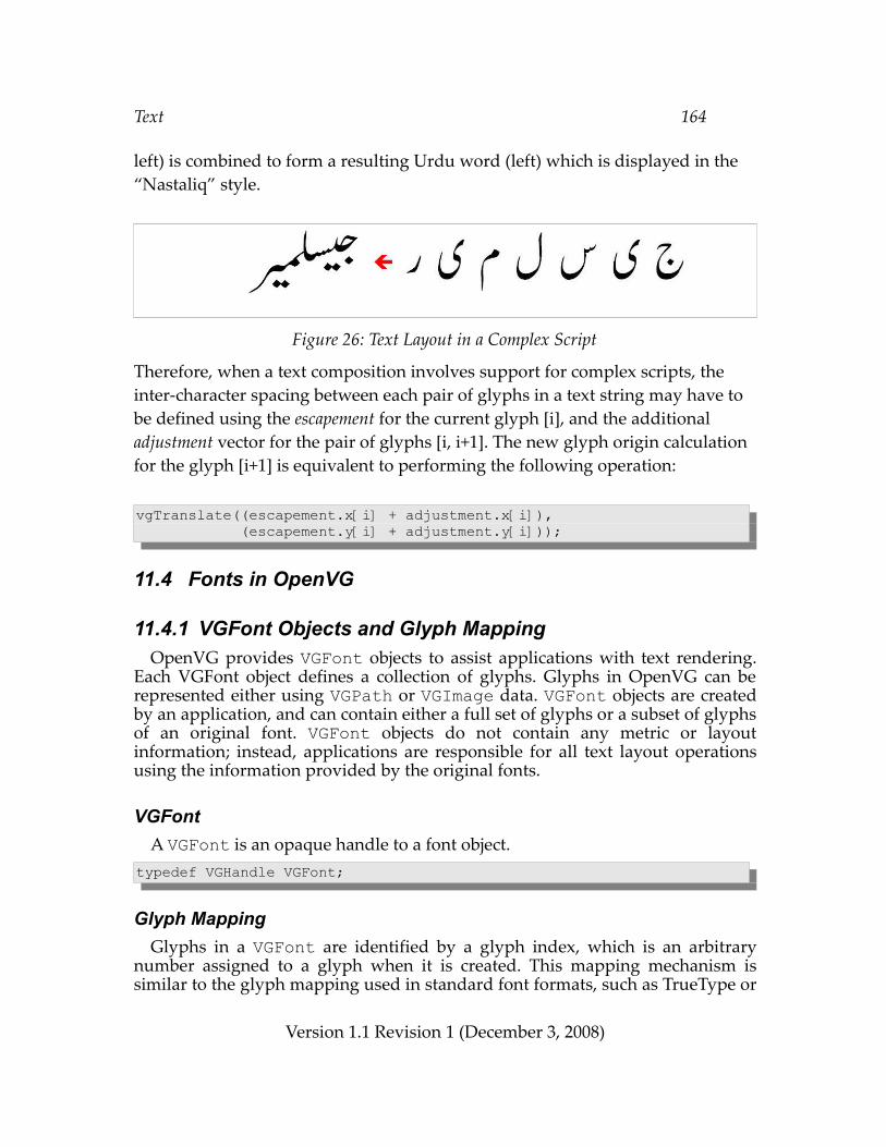
Text 164
left) is combined to form a resulting Urdu word (left) which is displayed in the “Nastaliq” style.
Figure 26: Text Layout in a Complex Script
Therefore, when a text composition involves support for complex scripts, the inter-character spacing between each pair of glyphs in a text string may have to be defined using the escapement for the current glyph [i], and the additional adjustment vector for the pair of glyphs [i, i+1]. The new glyph origin calculation for the glyph [i+1] is equivalent to performing the following operation:
vgTranslate((escapement.x[i] + adjustment.x[i]), (escapement.y[i] + adjustment.y[i]));
11.4 Fonts in OpenVG
11.4.1 VGFont Objects and Glyph MappingOpenVG provides VGFont objects to assist applications with text rendering.
Each VGFont object defines a collection of glyphs. Glyphs in OpenVG can be represented either using VGPath or VGImage data. VGFont objects are created by an application, and can contain either a full set of glyphs or a subset of glyphs of an original font. VGFont objects do not contain any metric or layout information; instead, applications are responsible for all text layout operations using the information provided by the original fonts.
VGFontA VGFont is an opaque handle to a font object.
typedef VGHandle VGFont;
Glyph MappingGlyphs in a VGFont are identified by a glyph index, which is an arbitrary
number assigned to a glyph when it is created. This mapping mechanism is similar to the glyph mapping used in standard font formats, such as TrueType or
Version 1.1 Revision 1 (December 3, 2008)
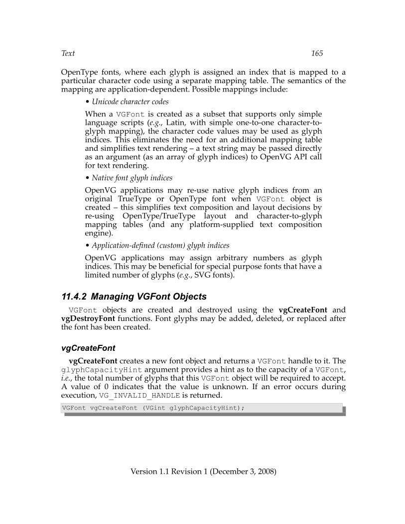
Text 165
OpenType fonts, where each glyph is assigned an index that is mapped to a particular character code using a separate mapping table. The semantics of the mapping are application-dependent. Possible mappings include:
• Unicode character codes When a VGFont is created as a subset that supports only simple language scripts (e.g., Latin, with simple one-to-one character-to-glyph mapping), the character code values may be used as glyph indices. This eliminates the need for an additional mapping table and simplifies text rendering – a text string may be passed directly as an argument (as an array of glyph indices) to OpenVG API call for text rendering. • Native font glyph indices OpenVG applications may re-use native glyph indices from an original TrueType or OpenType font when VGFont object is created – this simplifies text composition and layout decisions by re-using OpenType/TrueType layout and character-to-glyph mapping tables (and any platform-supplied text composition engine). • Application-defined (custom) glyph indices OpenVG applications may assign arbitrary numbers as glyph indices. This may be beneficial for special purpose fonts that have a limited number of glyphs (e.g., SVG fonts).
11.4.2 Managing VGFont ObjectsVGFont objects are created and destroyed using the vgCreateFont and
vgDestroyFont functions. Font glyphs may be added, deleted, or replaced after the font has been created.
vgCreateFontvgCreateFont creates a new font object and returns a VGFont handle to it. The
glyphCapacityHint argument provides a hint as to the capacity of a VGFont, i.e., the total number of glyphs that this VGFont object will be required to accept. A value of 0 indicates that the value is unknown. If an error occurs during execution, VG_INVALID_HANDLE is returned.VGFont vgCreateFont (VGint glyphCapacityHint);
Version 1.1 Revision 1 (December 3, 2008)
Text 166
ERRORSVG_ILLEGAL_ARGUMENT_ERROR– if glyphCapacityHint is negative
vgDestroyFontvgDestroyFont destroys the VGFont object pointed to by the font argument. Note that vgDestroyFont will not destroy underlying objects that were used to
define glyphs in the font. It is the responsibility of an application to destroy all VGPath or VGImage objects that were used in a VGFont, if they are no longer in use.void vgDestroyFont (VGFont font);
ERRORSVG_BAD_HANDLE_ERROR– if font is not a valid font handle, or is not shared with the current context
11.4.3 Querying VGFont Objects
VGFontParamType Values from the VGFontParamType enumeration can be used as the
paramType argument to vgGetParameter to query font features. All of the parameters defined by VGFontParamType are read-only. In the current specification, the single value VG_FONT_NUM_GLYPHS is defined.typedef enum { VG_FONT_NUM_GLYPHS = 0x2F00} VGFontParamType;
Parameter Datatype
VG_FONT_NUM_GLYPHS VGint
Table 14: VGFontParamType Datatypes
Version 1.1 Revision 1 (December 3, 2008)
Text 167
Number of GlyphsThe actual number of glyphs in a font (not the hinted capacity) is queried
using the VG_FONT_NUM_GLYPHS parameter. VGFont font;VGint numGlyphs = vgGetParameteri(font, VG_FONT_NUM_GLYPHS);
11.4.4 Adding and Modifying Glyphs in VGFontsVGFonts are collections of glyph data and may have glyphs represented using
VGPath objects (for vector outline fonts) or VGImage objects (for bitmap fonts). VGFont may be created for a particular target text size, where the glyphs can be defined using either scaled and hinted outlines or embedded bitmaps. The vgSetGlyphToPath, vgSetGlyphToImage, and vgClearGlyph functions are provided to add and/or modify glyphs in a VGFont.
A call to vgSetGlyphToPath or vgSetGlyphToImage increases the reference count of the provided VGPath or VGImage if the function call completes without producing an error. A call to vgClearGlyph, setting an existing glyph to a different VGPath or VGImage, or destroying the VGFont decreases the reference count for the referenced object. When the reference count of an object falls to 0, the resources of the object are released.
Applications are responsible for destroying path or image objects they have assigned as font glyphs. It is recommended that applications destroy the path or image using vgDestroyPath or vgDestroyImage immediately after setting the object as a glyph. Since path and image objects are reference counted, destroying the object will mark its handle as invalid while leaving the resource available to the VGFont object. This usage model will prevent inadvertent modification of path and image objects, and may allow implementations to optimize the storage and rendering of the referenced data. Applications can re-assign a new path object to the same glyphIndex in a font by simply calling vgSetGlyphToPath with the new path argument, in which case the number of glyphs remains the same.
A VGFont may have glyphs defined as a mix of vector outlines and bitmaps. The VG_MATRIX_GLYPH_USER_TO_SURFACE matrix controls the mapping from glyph coordinates to drawing surface coordinates.
Implementations may improve the quality of text rendering by applying optional auto-hinting of unhinted glyph outlines. Glyph outlines that are scaled and hinted at very small sizes may exhibit missing pixels (dropouts) when rendered in B/W mode without antialiasing. OpenVG implementations may attempt to improve the quality of B/W glyph rendering at small sizes by
Version 1.1 Revision 1 (December 3, 2008)
Text 168
identifying and drawing such pixels.It is recommended that when a path object defines the original unhinted glyph
outline, the scale parameter of the path object should be set to a value of 1/units-per-EM to achieve the effective size of 1 pixel per EM. This allows path data to be independent of the design unit metrics and original font format, and simplifies affine transformations applied to a glyph. For example, applying an affine transform with the matrix elements sx = sy = 12 would result in scaling the glyph to 12 pixels (or 12 units in the surface coordinate system). Both the glyphOrigin and escapement values are scaled identically.
Original font glyphs that are vector outlines are designed in a device-independent coordinate system (design units). The scale of the design coordinates is determined by the EM size (defined as “units-per-EM”) – a number that represents the distance between two adjacent, non-adjusted baselines of text.
If a path object defines a scaled and hinted glyph outline, its scale parameter should be set to 1. Since the process of scaling and hinting of original glyph outlines is based on fitting the outline contour's control points to the pixel grid of the destination surface, applying affine transformations to a path (other than translations mapped to the pixel grid in surface coordinate system) may reduce glyph legibility and should be avoided as much as possible.
vgSetGlyphToPathvgSetGlyphToPath creates a new glyph and assigns the given path to a glyph
associated with the glyphIndex in a font object. The glyphOrigin argument defines the coordinates of the glyph origin within the path, and the escapement parameter determines the advance width for this glyph (see Figure24). Both glyphOrigin and escapement coordinates are defined in the same coordinate system as the path. For glyphs that have no visual representation (e.g., the <space> character), a value of VG_INVALID_HANDLE is used for path. The reference count for the path is incremented.
The path object may define either an original glyph outline, or an outline that has been scaled and hinted to a particular size (in surface coordinate units); this is defined by the isHinted parameter, which can be used by implementation for text-specific optimizations (e.g., heuristic auto-hinting of unhinted outlines). When isHinted is equal to VG_TRUE, the implementation will never apply auto-hinting; otherwise, auto hinting will be applied at the implementation's discretion.void vgSetGlyphToPath(VGFont font, VGuint glyphIndex, VGPath path, VGboolean isHinted, const VGfloat glyphOrigin[2],
Version 1.1 Revision 1 (December 3, 2008)
Text 169
const VGfloat escapement[2]);
ERRORSVG_BAD_HANDLE_ERROR– if font is not a valid font handle, or is not shared with the current context
– if path is not a valid font handle or VG_INVALID_HANDLE, or is not shared with the current context
VG_ILLEGAL_ARGUMENT_ERROR– if the pointer to glyphOrigin or escapement is NULL or is not properly
aligned
vgSetGlyphToImagevgSetGlyphToImage creates a new glyph and assigns the given image into a
glyph associated with the glyphIndex in a font object. The glyphOrigin argument defines the coordinates of the glyph origin within the image, and the escapement parameter determines the advance width for this glyph (see Figure24). Both glyphOrigin and escapement coordinates are defined in the image coordinate system. Applying transformations to an image (other than translations mapped to pixel grid in surface coordinate system) should be avoided as much as possible. For glyphs that have no visual representation (e.g., the <space> character), a value of VG_INVALID_HANDLE is used for image. The reference count for the image is incremented.void vgSetGlyphToImage(VGFont font, VGuint glyphIndex, VGImage image, const VGfloat glyphOrigin[2], const VGfloat escapement[2]);
Version 1.1 Revision 1 (December 3, 2008)
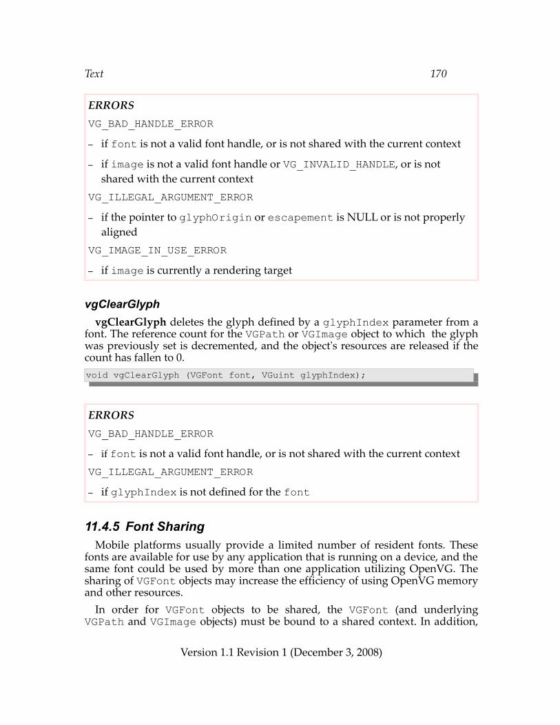
Text 170
ERRORSVG_BAD_HANDLE_ERROR– if font is not a valid font handle, or is not shared with the current context
– if image is not a valid font handle or VG_INVALID_HANDLE, or is not shared with the current context
VG_ILLEGAL_ARGUMENT_ERROR– if the pointer to glyphOrigin or escapement is NULL or is not properly
alignedVG_IMAGE_IN_USE_ERROR– if image is currently a rendering target
vgClearGlyphvgClearGlyph deletes the glyph defined by a glyphIndex parameter from a
font. The reference count for the VGPath or VGImage object to which the glyph was previously set is decremented, and the object's resources are released if the count has fallen to 0.void vgClearGlyph (VGFont font, VGuint glyphIndex);
ERRORSVG_BAD_HANDLE_ERROR– if font is not a valid font handle, or is not shared with the current contextVG_ILLEGAL_ARGUMENT_ERROR– if glyphIndex is not defined for the font
11.4.5 Font SharingMobile platforms usually provide a limited number of resident fonts. These
fonts are available for use by any application that is running on a device, and the same font could be used by more than one application utilizing OpenVG. The sharing of VGFont objects may increase the efficiency of using OpenVG memory and other resources.
In order for VGFont objects to be shared, the VGFont (and underlying VGPath and VGImage objects) must be bound to a shared context. In addition,
Version 1.1 Revision 1 (December 3, 2008)
Text 171
applications that create a font must share the following additional information about the font object:
• the relationship between original fonts and VGFont objects created by the application; • the character subset for which a particular VGFont object was created (if applicable); • the point or "pixels per EM" size (if applicable), for which a VGFont object was created; and• the custom mapping between character codes and glyph indices in the VGFont object.
In order to avoid additional complexity associated with character-to-glyph mapping, it is recommended that shared VGFont objects utilize character-to-glyph mappings based on either Unicode or native OpenType/TrueType glyph indices., as the use of custom glyph indices requires maintaining a standalone character-to glyph mapping table for each VGFont object.
11.5 Text Layout and RenderingOpenVG provides a dedicated glyph rendering API to assist applications in
compositing, layout, and rendering of text. Implementations may apply specific optimizations for rendering of glyphs. For example, auto-hinting algorithms that attempt to “snap” glyph outlines to the pixel grid may be used to improve the quality of text rendering for VGFont objects that contain unhinted glyph outlines. Autohinting may not be appropriate for animated text or when precise glyph placement is required.
vgDrawGlyphvgDrawGlyph renders a glyph defined by the glyphIndex using the given
font object. The user space position of the glyph (the point where the glyph origin will be placed) is determined by value of VG_GLYPH_ORIGIN.
vgDrawGlyph calculates the new text origin by translating the glyph origin by the escapement vector of the glyph defined by glyphIndex. Following the call, the VG_GLYPH_ORIGIN parameter will be updated with the new origin.
The paintModes parameter controls how glyphs are rendered. If paintModes is 0, neither VGImage-based nor VGPath-based glyphs are drawn. This mode is useful for determining the metrics of the glyph sequence. If paintModes is equal to one of VG_FILL_PATH, VG_STROKE_PATH, or (VG_FILL_PATH | VG_STROKE_PATH), path-based glyphs are filled, stroked (outlined), or both, respectively, and image-based glyphs are drawn.
When the allowAutoHinting flag is set to VG_FALSE, rendering occurs
Version 1.1 Revision 1 (December 3, 2008)
Text 172
without hinting. If allowAutoHinting is equal to VG_TRUE, autohinting may be optionally applied to alter the glyph outlines slightly for better rendering quality. In this case, the escapement values will be adjusted to match the effects of hinting. Autohinting is not applied to image-based glyphs or path-based glyphs marked as isHinted in vgSetGlyphToPath.void vgDrawGlyph(VGFont font, VGuint glyphIndex, VGbitfield paintModes, VGboolean allowAutoHinting);
ERRORSVG_BAD_HANDLE_ERROR– if font is not a valid font handle, or is not shared with the current contextVG_ILLEGAL_ARGUMENT_ERROR– if glyphIndex has not been defined for a given font object
– if paintModes is not a valid bitwise OR of values from the VGPaintMode enumeration, or 0
vgDrawGlyphsvgDrawGlyphs renders a sequence of glyphs defined by the array pointed to
by glyphIndices using the given font object. The values in the adjustments_x and adjustments_y arrays define positional adjustment values for each pair of glyphs defined by the glyphIndices array. The glyphCount parameter defines the number of elements in the glyphIndices and adjustments_x and adjustments_y arrays. The adjustment values defined in these arrays may represent kerning or other positional adjustments required for each pair of glyphs. If no adjustments for glyph positioning in a particular axis are required (all horizontal and/or vertical adjustments are zero), NULL pointers may be passed for either or both of adjustment_x and adjustment_y. The adjustments values should be defined in the same coordinate system as the font glyphs; if the glyphs are defined by path objects with path data scaled (e.g., by a factor of 1/units-per-EM), the values in the adjustment_x and adjustment_y arrays are scaled using the same scale factor.
The user space position of the first glyph (the point where the glyph origin will be placed) is determined by the value of VG_GLYPH_ORIGIN.
vgDrawGlyphs calculates a new glyph origin for every glyph in the glyphIndices array by translating the glyph origin by the escapement vector
Version 1.1 Revision 1 (December 3, 2008)
Text 173
of the current glyph, and applying the necessary positional adjustments (see Section 11.3), taking into account both the escapement values associated with the glyphs as well as the adjustments_x and adjustments_y parameters. Following the call, the VG_GLYPH_ORIGIN parameter will be updated with the new origin.
The paintModes parameter controls how glyphs are rendered. If paintModes is 0, neither VGImage-based nor VGPath-based glyphs are drawn. This mode is useful for determining the metrics of the glyph sequence. If paintModes equals VG_FILL_PATH, VG_STROKE_PATH, or VG_FILL_PATH | VG_STROKE_PATH, path-based glyphs are filled, stroked (outlined), or both, respectively, and image-based glyphs are drawn.
When the allowAutoHinting flag is set to VG_FALSE, rendering occurs without hinting. If allowAutoHinting is equal to VG_TRUE, autohinting may be optionally applied to alter the glyph outlines slightly for better rendering quality. In this case, the escapement values will be adjusted to match the effects of hinting.void vgDrawGlyphs(VGFont font, VGint glyphCount, const VGuint * glyphIndices, const VGfloat * adjustments_x, const VGfloat * adjustments_y, VGbitfield paintModes, VGboolean allowAutoHinting);
ERRORSVG_BAD_HANDLE_ERROR– if font is not a valid font handle, or is not shared with the current contextVG_ILLEGAL_ARGUMENT_ERROR– if glyphCount is zero or a negative value
– if the pointer to the glyphIndices array is NULL or is not properly aligned
– if a pointer to either of the adjustments_x or adjustments_y arrays are non-NULL and are not properly aligned
– if any of the glyphIndices has not been defined in a given font object
– if paintModes is not a valid bitwise OR of values from the VGPaintMode enumeration, or 0
Version 1.1 Revision 1 (December 3, 2008)
Image Filters 174
12 Image FiltersImage filters allow images to be modified and/or combined using a variety of imaging operations. Operations are carried out using a bit depth greater than or equal to the largest bit depth of the supplied images. The lower-left corners of all source and destination images are aligned. The destination area to be written is the intersection of the source and destination image areas. The entire source image area is used as the filter input. The source and destination images involved in the filter operation must not overlap (i.e., have any pixels in common within any common ancestor image). Source and destination images may have a common ancestor as long as they occupy disjoint areas within that area.
12.1 Format NormalizationA series of steps are carried out on application-supplied source images in order to produce normalized source images for filtering. In practice, these normalizations may be combined with the filter operations themselves for efficiency.
The source pixels are converted to one of sRGBA, sRGBA_PRE, lRGBA, or lRGBA_PRE formats, as determined by the current values of the VG_FILTER_FORMAT_PREMULTIPLIED and VG_FILTER_FORMAT_LINEAR parameters. The conversions take place in the following order (equivalent to the conversion rules defined in Section 3.4):
1) Source color and alpha values are scaled linearly to lie in a [0, 1] range. The exact precision of the internal representation is implementation-dependent.
2) If the source image has premultiplied alpha, the alpha values are divided out of each source color channel, and stored for later use. If the source image has no alpha channel, an alpha value of 1 is added to each pixel.
3) If the source pixel is in a grayscale format (lL or sL), it is converted to an RGB format (lRGB or sRGB, respectively) by replication.
4) If the VG_FILTER_FORMAT_LINEAR parameter is set to VG_TRUE, and the source pixel is in non-linear format, it is converted into the corresponding linear format (sRGBA→lRGBA). If the VG_FILTER_FORMAT_LINEAR parameter is set to VG_FALSE, and the source pixel is in linear format, it is converted into the corresponding non-linear format (lRGBA→sRGBA).
5) If the VG_FILTER_FORMAT_PREMULTIPLIED parameter is equal to VG_TRUE, each source color channel is multiplied by the corresponding alpha value. Otherwise, the color channels are left undisturbed.
An implementation may collapse steps algebraically; for example, if no conversion is to
Version 1.1 Revision 1 (December 3, 2008)
Image Filters 175
take place in step 4, the division and multiplication by alpha in steps 2 and 5 may be implemented as a no-op.
The resulting pixel will be in sRGBA, sRGBA_PRE, lRGBA, or lRGBA_PRE format. The image filter then processes each of the four source channels in an identical manner, resulting in a set of filtered pixels in the same pixel format as the incoming pixels.
Finally, the filtered pixels are converted into the destination format using the normal pixel format conversion rules, as described in section 3.4. Premultiplied alpha values are divided out prior to color-space conversion, and restored afterwards if necessary. The destination channels specified by the VG_FILTER_CHANNEL_MASK parameter (see below) are written into the destination image.
12.2 Channel Masks
VGImageChannelAll image filter functions make use of the VG_FILTER_CHANNEL_MASK parameter that specifies which destination channels are to be written. The parameter is supplied as a bitwise OR of values from the VGImageChannel enumeration. If the destination pixel format is one of VG_sL_8, VG_lL_8 or VG_BW_1 pixel format, the parameter is ignored. If the destination pixel format does not contain an alpha channel, the VG_ALPHA bit is ignored. Bits other than those defined by the VGImageChannel enumeration are ignored.
VG_FILTER_CHANNEL_MASK controls which color channels of the filtered image are written into the destination image. In the case where the destination image is premultiplied, and VG_FILTER_CHANNEL_MASK does not specify that all channels are to be written, the following steps are taken to ensure consistency:
1. If VG_FILTER_FORMAT_PREMULTIPLIED is enabled, the filtered color channels are clamped to the range [0, alpha], and converted into non-premultiplied form (as described in Section 3.4)
2. The resulting color is converted into the destination color space3. The destination is read and converted into non-premultiplied form
4. The destination channels specified by VG_FILTER_CHANNEL_MASK are replaced by the corresponding filtered values
5. The results are converted into premultiplied form and written to the destination image
Version 1.1 Revision 1 (December 3, 2008)
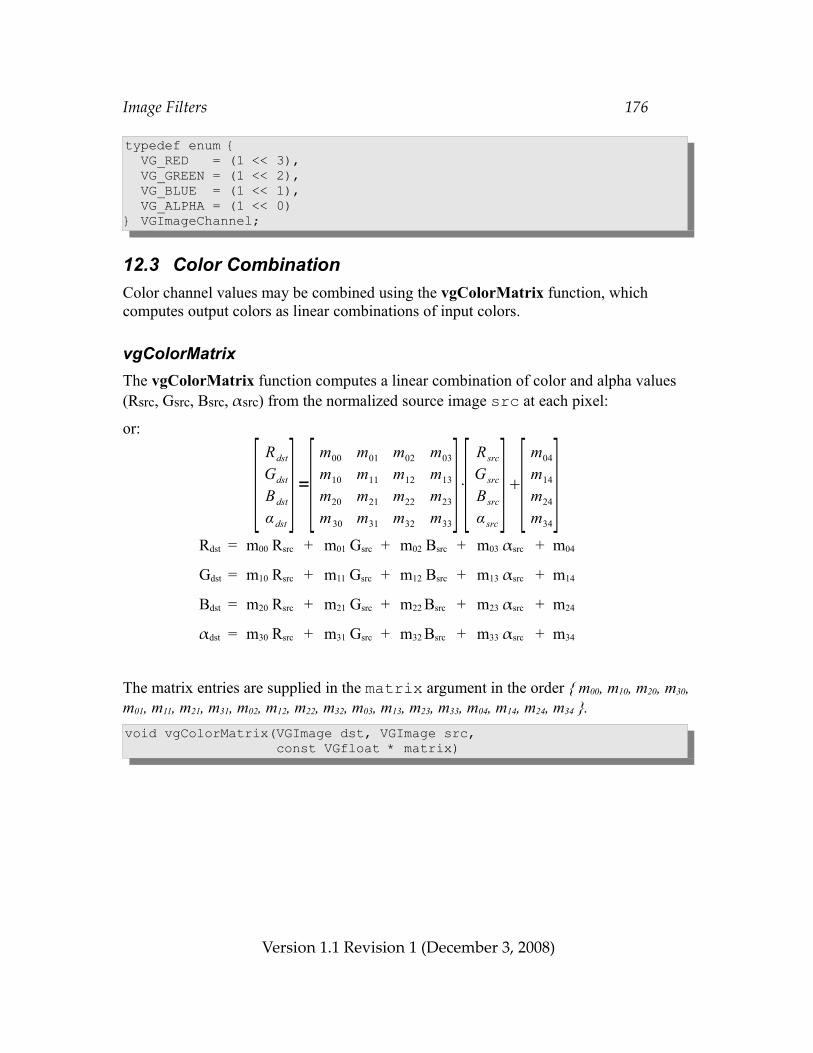
Image Filters 176
typedef enum { VG_RED = (1 << 3), VG_GREEN = (1 << 2), VG_BLUE = (1 << 1), VG_ALPHA = (1 << 0)} VGImageChannel;
12.3 Color CombinationColor channel values may be combined using the vgColorMatrix function, which computes output colors as linear combinations of input colors.
vgColorMatrixThe vgColorMatrix function computes a linear combination of color and alpha values (Rsrc, Gsrc, Bsrc, αsrc) from the normalized source image src at each pixel:
or:
Rdst = m00 Rsrc + m01 Gsrc + m02 Bsrc + m03 αsrc + m04
Gdst = m10 Rsrc + m11 Gsrc + m12 Bsrc + m13 αsrc + m14
Bdst = m20 Rsrc + m21 Gsrc + m22 Bsrc + m23 αsrc + m24
αdst = m30 Rsrc + m31 Gsrc + m32 Bsrc + m33 αsrc + m34
The matrix entries are supplied in the matrix argument in the order { m00, m10, m20, m30, m01, m11, m21, m31, m02, m12, m22, m32, m03, m13, m23, m33, m04, m14, m24, m34 }.void vgColorMatrix(VGImage dst, VGImage src, const VGfloat * matrix)
Version 1.1 Revision 1 (December 3, 2008)
[ Rdst
Gdst
Bdst
α dst]=[ m00 m01 m02 m03
m10 m11 m12 m13
m20 m21 m22 m23
m30 m31 m32 m33]⋅[ R src
G src
B src
α src][ m04
m14
m24
m34]
Image Filters 177
ERRORSVG_BAD_HANDLE_ERROR– if either dst or src is not a valid image handle, or is not shared with the
current contextVG_IMAGE_IN_USE_ERROR– if either dst or src is currently a rendering targetVG_ILLEGAL_ARGUMENT_ERROR– if src and dst overlap
– if matrix is NULL– if matrix is not properly aligned
12.4 ConvolutionThe vgConvolve, vgSeparableConvolve, and vgGaussianBlur functions define destination pixels based on a weighted average of neighboring source pixels, a process known as convolution. The set of weights, along with their relative locations, is known as the convolution kernel. In the discussion below, width and height refer to the dimensions of the source image.
VG_MAX_KERNEL_SIZEThe VG_MAX_KERNEL_SIZE parameter contains the largest legal value of the width and height parameters to the vgConvolve function. All implementations must define VG_MAX_KERNEL_SIZE to be an integer no smaller than 7. If there is no implementation-defined limit, a value of VG_MAXINT may be returned. The value may be retrieved by calling vgGeti:VGint maxKernelSize = vgGeti(VG_MAX_KERNEL_SIZE);
VG_MAX_SEPARABLE_KERNEL_SIZEThe VG_MAX_SEPARABLE_KERNEL_SIZE parameter contains the largest legal value of the size parameter to the vgSeparableConvolve function. All implementations must define VG_MAX_SEPARABLE_KERNEL_SIZE to be an integer no smaller than 15. If there is no implementation-defined limit, a value of VG_MAXINT may be returned. The value may be retrieved by calling vgGeti:
Version 1.1 Revision 1 (December 3, 2008)
Image Filters 178
VGint maxSeparableKernelSize = vgGeti(VG_MAX_SEPARABLE_KERNEL_SIZE);
VG_MAX_GAUSSIAN_STD_DEVIATIONThe VG_MAX_GAUSSIAN_STD_DEVIATION parameter contains the largest legal value of the stdDeviationX and stdDeviationY parameters to the vgGaussianBlur function. All implementations must define VG_MAX_GAUSSIAN_STD_DEVIATION to be an integer no smaller than 16. If there is no implementation-defined limit, a value of VG_MAXINT may be returned. The value may be retrieved by calling vgGeti:VGint maxGaussianStdDeviation = vgGeti(VG_MAX_GAUSSIAN_STD_DEVIATION);
vgConvolveThe vgConvolve function applies a user-supplied convolution kernel to a normalized source image src. The dimensions of the kernel are given by kernelWidth and kernelHeight; the kernel values are specified as kernelWidth*kernelHeight VGshorts in column-major order. That is, the kernel entry (i, j) is located at position i*kernelHeight + j in the input sequence. The shiftX and shiftY parameters specify a translation between the source and destination images. The result of the convolution is multiplied by a scale factor, and a bias is added.
The output pixel (x, y) is defined as:
where w = kernelWidth, h = kernelHeight, ki,j is the kernel element at position (i, j), s is the scale, b is the bias, and p(x, y) is the source pixel at (x, y), or the result of source edge extension defined by tilingMode, which takes a value from the VGTilingMode enumeration (see Section 9.4.1). Note that the use of the kernel index (w–i–1, h–j–1) implies that the kernel is rotated 180 degrees relative to the source image in order to conform to the mathematical definition of convolution when shiftX = w – 1 and shiftY = h - 1. Figure 27 depicts the flipping of the kernel relative to the image pixels for a 3x3 kernel.
The operation is applied to all channels (color and alpha) independently.
Version 1.1 Revision 1 (December 3, 2008)
s∑0≤iw∑0≤ jh k w−i−1 ,h− j−1 pxi – shiftX , y j – shiftY b ,
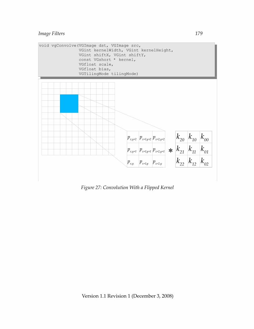
Image Filters 179
void vgConvolve(VGImage dst, VGImage src, VGint kernelWidth, VGint kernelHeight, VGint shiftX, VGint shiftY, const VGshort * kernel, VGfloat scale, VGfloat bias, VGTilingMode tilingMode)
Figure 27: Convolution With a Flipped Kernel
Version 1.1 Revision 1 (December 3, 2008)
*
k20 k10 k00
k21 k11 k01
k22 k12 k02
px,y+2 px+1,y+2 px+2,y+2
px+1,y+1 px+2,y+1
px+2,y
px,y+1
px,y px+1,y
Image Filters 180
ERRORSVG_BAD_HANDLE_ERROR– if either dst or src is not a valid image handle, or is not shared with the
current contextVG_IMAGE_IN_USE_ERROR– if either dst or src is currently a rendering targetVG_ILLEGAL_ARGUMENT_ERROR– if src and dst overlap
– if kernelWidth or kernelHeight is less than or equal to 0 or greater than VG_MAX_KERNEL_SIZE
– if kernel is NULL– if kernel is not properly aligned
– if tilingMode is not one of the values from the VGTilingMode enumeration
vgSeparableConvolveThe vgSeparableConvolve function applies a user-supplied separable convolution kernel to a normalized source image src. A separable kernel is a two-dimensional kernel in which each entry kij is equal to a product kxi * kyj of elements from two one-dimensional kernels, one horizontal and one vertical.The lengths of the one-dimensional arrays kernelX and kernelY are given by kernelWidth and kernelHeight, respectively; the kernel values are specified as arrays of VGshorts. The shiftX and shiftY parameters specify a translation between the source and destination images. The result of the convolution is multiplied by a scale factor, and a bias is added.
The output pixel (x, y) is defined as:
where w = kernelWidth, h = kernelHeight, kxi is the one-dimensional horizontal kernel element at position i, kyj is the one-dimensional vertical kernel element at position j, s is the scale, b is the bias, and p(x, y) is the source pixel at (x, y), or the result of
Version 1.1 Revision 1 (December 3, 2008)
s∑0≤iw∑0≤ jh kxw−i−1 kyh− j−i p xi – shiftX , y j – shiftY b ,
Image Filters 181
source edge extension defined by tilingMode, which takes a value from the VGTilingMode enumeration (see Section 9.4.1). Note that the use of the kernel indices (w–i–1) and (h–j–1) implies that the kernel is rotated 180 degrees relative to the source image in order to conform to the mathematical definition of convolution.
The operation is applied to all channels (color and alpha) independently.void vgSeparableConvolve(VGImage dst, VGImage src, VGint kernelWidth, VGint kernelHeight, VGint shiftX, VGint shiftY, const VGshort * kernelX, const VGshort * kernelY, VGfloat scale, VGfloat bias, VGTilingMode tilingMode)
ERRORSVG_BAD_HANDLE_ERROR– if either dst or src is not a valid image handle, or is not shared with the
current contextVG_IMAGE_IN_USE_ERROR– if either dst or src is currently a rendering targetVG_ILLEGAL_ARGUMENT_ERROR– if src and dst overlap
– if kernelWidth or kernelHeight is less than or equal to 0 or greater than VG_MAX_SEPARABLE_KERNEL_SIZE
– if kernelX or kernelY is NULL– if kernelX or kernelY is not properly aligned
– if tilingMode is not one of the values from the VGTilingMode enumeration
vgGaussianBlurThe vgGaussianBlur function computes the convolution of a normalized source image src with a separable kernel defined in each dimension by the Gaussian function G(x, s):
Version 1.1 Revision 1 (December 3, 2008)
Image Filters 182
where s is the standard deviation.
The two-dimensional kernel is defined by multiplying together two one-dimensional kernels, one for each axis:
where sx and sy are the (positive) standard deviations in the horizontal and vertical directions, given by the stdDeviationX and stdDeviationY parameters respectively. This kernel has special properties that allow for very efficient implementation; for example, the implementation may use multiple passes with simple kernels to obtain the same overall result with higher performance than direct convolution. If stdDeviationX and stdDeviationY are equal, the kernel is rotationally symmetric.
Source pixels outside the source image bounds are defined by tilingMode, which takes a value from the VGTilingMode enumeration (see Section 9.4.1)
The operation is applied to all channels (color and alpha) independently.void vgGaussianBlur(VGImage dst, VGImage src, VGfloat stdDeviationX, VGfloat stdDeviationY, VGTilingMode tilingMode)
Version 1.1 Revision 1 (December 3, 2008)
k x , y =G x , s x∗G y , s y=1
2 s x s y
e− x2
2 sx2
y2
2 s y2
Gx , s= 1 2 s2
e− x2
2 s2
Image Filters 183
ERRORSVG_BAD_HANDLE_ERROR– if either dst or src is not a valid image handle, or is not shared with the
current contextVG_IMAGE_IN_USE_ERROR– if either dst or src is currently a rendering targetVG_ILLEGAL_ARGUMENT_ERROR– if src and dst overlap
– if stdDeviationX or stdDeviationY is less than or equal to 0 or greater than VG_MAX_GAUSSIAN_STD_DEVIATION
– if tilingMode is not one of the values from the VGTilingMode enumeration
12.5 Lookup Tables
vgLookupThe vgLookup function passes each image channel of the normalized source image src through a separate lookup table.
Each channel of the normalized source pixel is used as an index into the lookup table for that channel by multiplying the normalized value by 255 and rounding to obtain an 8-bit integral value. Each LUT parameter should contain 256 VGubyte entries. The outputs of the lookup tables are concatenated to form an RGBA_8888 pixel value, which is interpreted as lRGBA_8888, lRGBA_8888_PRE, sRGBA_8888, or sRGBA_8888_PRE, depending on the values of outputLinear and outputPremultiplied.
The resulting pixels are converted into the destination format using the normal pixel format conversion rules.
Version 1.1 Revision 1 (December 3, 2008)
Image Filters 184
void vgLookup(VGImage dst, VGImage src, const VGubyte * redLUT, const VGubyte * greenLUT, const VGubyte * blueLUT, const VGubyte * alphaLUT, VGboolean outputLinear, VGboolean outputPremultiplied)
ERRORSVG_BAD_HANDLE_ERROR– if either dst or src is not a valid image handle, or is not shared with the
current contextVG_IMAGE_IN_USE_ERROR– if either dst or src is currently a rendering targetVG_ILLEGAL_ARGUMENT_ERROR– if src and dst overlap
– if any pointer parameter is NULL
vgLookupSingleThe vgLookupSingle function passes a single image channel of the normalized source image src, selected by the sourceChannel parameter, through a combined lookup table that produces whole pixel values. Each normalized source channel value is multiplied by 255 and rounded to obtain an 8 bit integral value.
The specified sourceChannel of the normalized source pixel is used as an index into the lookup table. If the source image is in a single-channel grayscale (VG_lL_8, VG_sL_8, or VG_BW_1) or alpha-only (VG_A_1, VG_A_4, or VG_A_8) format, the sourceChannel parameter is ignored and the single channel is used. The lookupTable parameter should contain 256 4-byte aligned entries in an RGBA_8888 pixel value, which is interpreted as lRGBA_8888, lRGBA_8888_PRE, sRGBA_8888, or sRGBA_8888_PRE, depending on the values of outputLinear and outputPremultiplied.
The resulting pixels are converted into the destination format using the normal pixel format conversion rules.
Version 1.1 Revision 1 (December 3, 2008)
Image Filters 185
void vgLookupSingle(VGImage dst, VGImage src, const VGuint * lookupTable, VGImageChannel sourceChannel, VGboolean outputLinear, VGboolean outputPremultiplied)
ERRORSVG_BAD_HANDLE_ERROR– if either dst or src is not a valid image handle, or is not shared with the
current contextVG_IMAGE_IN_USE_ERROR– if either dst or src is currently a rendering targetVG_ILLEGAL_ARGUMENT_ERROR– if src and dst overlap
– if src is in an RGB pixel format and sourceChannel is not one of VG_RED, VG_GREEN, VG_BLUE or VG_ALPHA from the VGImageChannel enumeration
– if lookupTable is NULL– if lookupTable is not properly aligned
13 Color Transformation and BlendingIn the final pipeline stage, the pixels from the previous pipeline stage (paint generation or image interpolation) are optionally transformed by a color transformation matrix. If image drawing is taking place using the VG_DRAW_IMAGE_STENCIL mode, the color transformation is applied to the incoming paint pixels.
The resulting pixels are converted into the destination color space, and blending is performed using a subset of the standard Porter-Duff blending rules [PORT84] along with several additional rules.
13.1 Color TransformationIf the VG_COLOR_TRANSFORM parameter is enabled, each color from the preceding pipeline stage (or the incoming paint color for the VG_DRAW_IMAGE_STENCIL computation) is converted to non-premultiplied form. If the color is in a luminance
Version 1.1 Revision 1 (December 3, 2008)
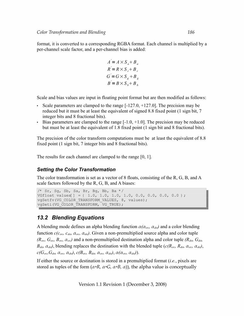
Color Transformation and Blending 186
format, it is converted to a corresponding RGBA format. Each channel is multiplied by a per-channel scale factor, and a per-channel bias is added:
Scale and bias values are input in floating point format but are then modified as follows:
• Scale parameters are clamped to the range [-127.0, +127.0]. The precision may be reduced but it must be at least the equivalent of signed 8.8 fixed point (1 sign bit, 7 integer bits and 8 fractional bits).
• Bias parameters are clamped to the range [-1.0, +1.0]. The precision may be reduced but must be at least the equivalent of 1.8 fixed point (1 sign bit and 8 fractional bits).
The precision of the color transform computations must be at least the equivalent of 8.8 fixed point (1 sign bit, 7 integer bits and 8 fractional bits).
The results for each channel are clamped to the range [0, 1].
Setting the Color TransformationThe color transformation is set as a vector of 8 floats, consisting of the R, G, B, and A scale factors followed by the R, G, B, and A biases:/* Sr, Sg, Sb, Sa, Br, Bg, Bb, Ba */VGfloat values[] = { 1.0, 1.0, 1.0, 1.0, 0.0, 0.0, 0.0, 0.0 };vgSetfv(VG_COLOR_TRANSFORM_VALUES, 8, values);vgSeti(VG_COLOR_TRANSFORM, VG_TRUE);
13.2 Blending EquationsA blending mode defines an alpha blending function α(αsrc, αdst) and a color blending function c(csrc, cdst, αsrc, αdst). Given a non-premultiplied source alpha and color tuple (Rsrc, Gsrc, Bsrc, αsrc) and a non-premultiplied destination alpha and color tuple (Rdst, Gdst, Bdst, αdst), blending replaces the destination with the blended tuple (c(Rsrc, Rdst, αsrc, αdst), c(Gsrc,Gdst, αsrc, αdst), c(Bsrc, Bdst, αsrc, αdst), α(αsrc, αdst)).
If either the source or destination is stored in a premultiplied format (i.e., pixels are stored as tuples of the form (α*R, α*G, α*B, α)), the alpha value is conceptually
Version 1.1 Revision 1 (December 3, 2008)
A '= A×S aBa
R '=R×S rB r
G '=G×S gB g
B '=B×S bB b
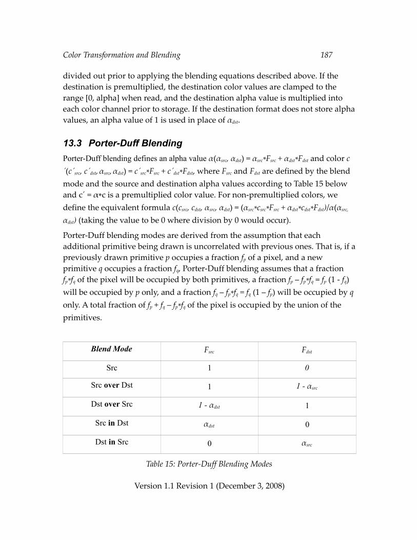
Color Transformation and Blending 187
divided out prior to applying the blending equations described above. If the destination is premultiplied, the destination color values are clamped to the range [0, alpha] when read, and the destination alpha value is multiplied into each color channel prior to storage. If the destination format does not store alpha values, an alpha value of 1 is used in place of αdst.
13.3 Porter-Duff BlendingPorter-Duff blending defines an alpha value α(αsrc, αdst) = αsrc*Fsrc + αdst*Fdst and color c´(c´src, c´dst, αsrc, αdst) = c´src*Fsrc + c´dst*Fdst, where Fsrc and Fdst are defined by the blend mode and the source and destination alpha values according to Table 15 below and c´ = α*c is a premultiplied color value. For non-premultiplied colors, we define the equivalent formula c(csrc, cdst, αsrc, αdst) = (αsrc*csrc*Fsrc + αdst*cdst*Fdst)/α(αsrc,
αdst) (taking the value to be 0 where division by 0 would occur).
Porter-Duff blending modes are derived from the assumption that each additional primitive being drawn is uncorrelated with previous ones. That is, if a previously drawn primitive p occupies a fraction fp of a pixel, and a new primitive q occupies a fraction fq, Porter-Duff blending assumes that a fraction fp*fq of the pixel will be occupied by both primitives, a fraction fp – fp*fq = fp (1 - fq) will be occupied by p only, and a fraction fq – fp*fq = fq (1 – fp) will be occupied by q only. A total fraction of fp + fq – fp*fq of the pixel is occupied by the union of the primitives.
Blend Mode Fsrc Fdst
Src 1 0
Src over Dst 1 1 - αsrc
Dst over Src 1 - αdst 1
Src in Dst αdst 0
Dst in Src 0 αsrc
Table 15: Porter-Duff Blending Modes
Version 1.1 Revision 1 (December 3, 2008)
Color Transformation and Blending 188
13.4 Additional Blending ModesA number of additional blending modes are available. These modes are a subset of the SVG image blending modes. Note that the SVG “Normal” blending mode is equivalent to the Porter-Duff “Src over Dst” mode described above. The additional blend modes have the following effects:• VG_BLEND_MULTIPLY – Multiply the source and destination colors together,
producing the effect of placing a transparent filter over a background. A black source pixel forces the destination to black, while a white source pixel leaves the destination unchanged. If all alpha values are 1, this reduces to multiplying the source and destination color values.
• VG_BLEND_SCREEN – The opposite of multiplication, producing the effect of projecting a slide over a background. A black source pixel leaves the destination unchanged, while a white source pixel forces the destination to white. If all alpha values are 1, this reduces to adding the source and destination color values, and subtracting their product.
• VG_BLEND_DARKEN – Compute (Src over Dst) and (Dst over Src) and take the smaller (darker) value for each channel. If all alpha values are 1, this reduces to choosing the smaller value for each color channel.
• VG_BLEND_LIGHTEN – Compute (Src over Dst) and (Dst over Src) and take the larger (lighter) value for each channel. If all alpha values are 1, this reduces to choosing the larger value for each color channel.
The new destination alpha value for the blending modes defined in this section is always equal to α(αsrc, αdst) = αsrc + αdst*(1 – αsrc), as for Porter-Duff “Src over Dst” blending. The formulas for each additional blending mode are shown in Table16. The right-hand column contains the pre-multiplied output values, that is, the products of the new color value c(csrc, cdst, αsrc, αdst) and alpha value α(αsrc, αdst). The source and destination color values csrc and cdst are given in non-premultiplied form.
Version 1.1 Revision 1 (December 3, 2008)
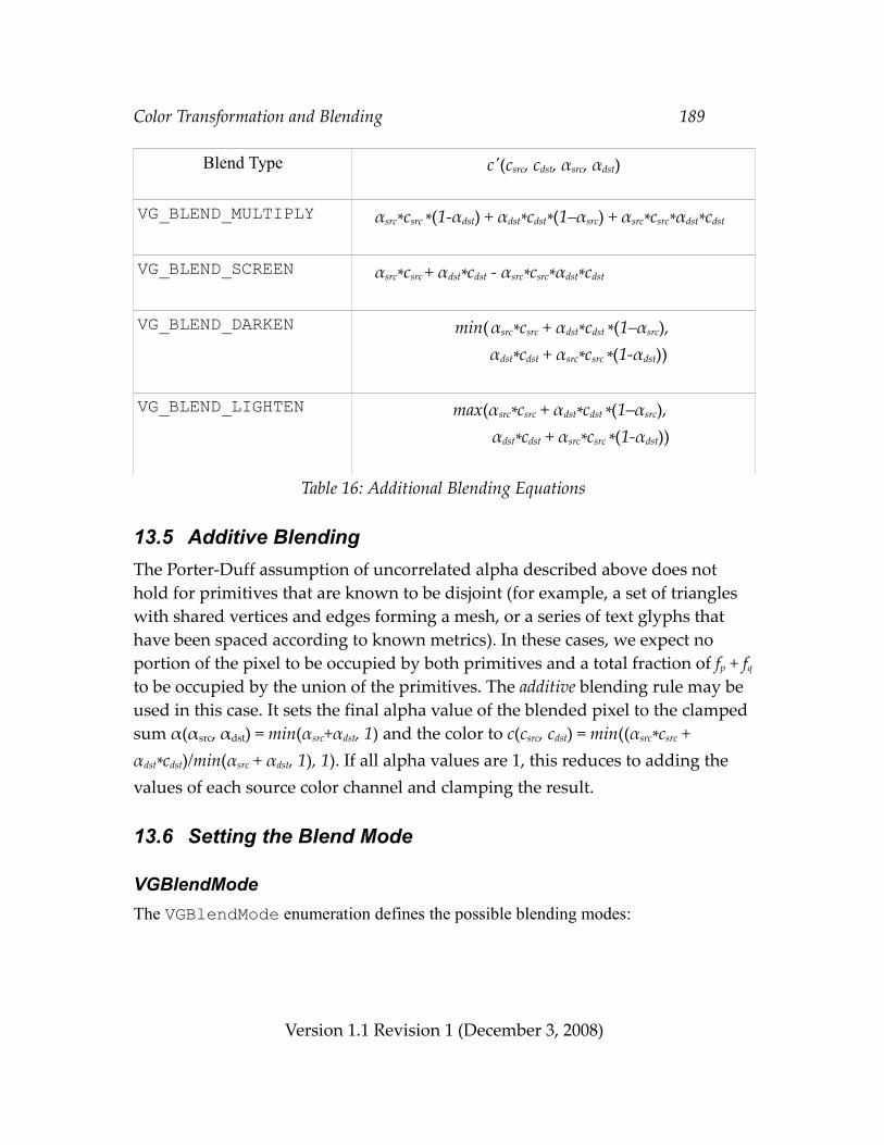
Color Transformation and Blending 189
Blend Type c'(csrc, cdst, αsrc, αdst)
VG_BLEND_MULTIPLY αsrc*csrc *(1-αdst) + αdst*cdst*(1–αsrc) + αsrc*csrc*αdst*cdst
VG_BLEND_SCREEN αsrc*csrc + αdst*cdst - αsrc*csrc*αdst*cdst
VG_BLEND_DARKEN min(αsrc*csrc + αdst*cdst *(1–αsrc),αdst*cdst + αsrc*csrc *(1-αdst))
VG_BLEND_LIGHTEN max(αsrc*csrc + αdst*cdst *(1–αsrc), αdst*cdst + αsrc*csrc *(1-αdst))
Table 16: Additional Blending Equations
13.5 Additive BlendingThe Porter-Duff assumption of uncorrelated alpha described above does not hold for primitives that are known to be disjoint (for example, a set of triangles with shared vertices and edges forming a mesh, or a series of text glyphs that have been spaced according to known metrics). In these cases, we expect no portion of the pixel to be occupied by both primitives and a total fraction of fp + fq
to be occupied by the union of the primitives. The additive blending rule may be used in this case. It sets the final alpha value of the blended pixel to the clamped sum α(αsrc, αdst) = min(αsrc+αdst, 1) and the color to c(csrc, cdst) = min((αsrc*csrc + αdst*cdst)/min(αsrc + αdst, 1), 1). If all alpha values are 1, this reduces to adding the values of each source color channel and clamping the result.
13.6 Setting the Blend Mode
VGBlendModeThe VGBlendMode enumeration defines the possible blending modes:
Version 1.1 Revision 1 (December 3, 2008)
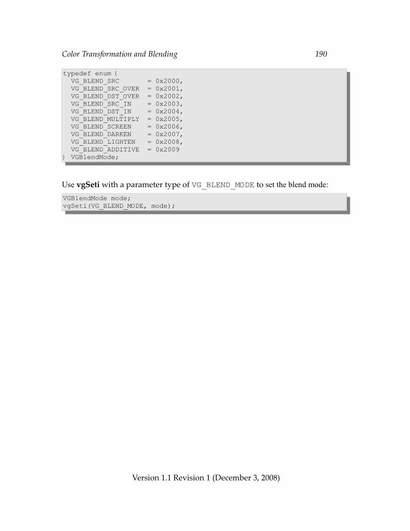
Color Transformation and Blending 190
typedef enum { VG_BLEND_SRC = 0x2000, VG_BLEND_SRC_OVER = 0x2001, VG_BLEND_DST_OVER = 0x2002, VG_BLEND_SRC_IN = 0x2003, VG_BLEND_DST_IN = 0x2004, VG_BLEND_MULTIPLY = 0x2005, VG_BLEND_SCREEN = 0x2006, VG_BLEND_DARKEN = 0x2007, VG_BLEND_LIGHTEN = 0x2008, VG_BLEND_ADDITIVE = 0x2009} VGBlendMode;
Use vgSeti with a parameter type of VG_BLEND_MODE to set the blend mode:VGBlendMode mode;vgSeti(VG_BLEND_MODE, mode);
Version 1.1 Revision 1 (December 3, 2008)
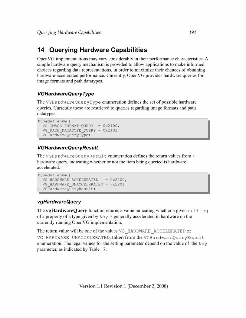
Querying Hardware Capabilities 191
14 Querying Hardware CapabilitiesOpenVG implementations may vary considerably in their performance characteristics. A simple hardware query mechanism is provided to allow applications to make informed choices regarding data representations, in order to maximize their chances of obtaining hardware-accelerated performance. Currently, OpenVG provides hardware queries for image formats and path datatypes.
VGHardwareQueryTypeThe VGHardwareQueryType enumeration defines the set of possible hardware queries. Currently these are restricted to queries regarding image formats and path datatypes.typedef enum { VG_IMAGE_FORMAT_QUERY = 0x2100, VG_PATH_DATATYPE_QUERY = 0x2101} VGHardwareQueryType;
VGHardwareQueryResultThe VGHardwareQueryResult enumeration defines the return values from a hardware query, indicating whether or not the item being queried is hardware accelerated.typedef enum { VG_HARDWARE_ACCELERATED = 0x2200, VG_HARDWARE_UNACCELERATED = 0x2201} VGHardwareQueryResult;
vgHardwareQueryThe vgHardwareQuery function returns a value indicating whether a given setting of a property of a type given by key is generally accelerated in hardware on the currently running OpenVG implementation.
The return value will be one of the values VG_HARDWARE_ACCELERATED or VG_HARDWARE_UNACCELERATED, taken from the VGHardwareQueryResult enumeration. The legal values for the setting parameter depend on the value of the key parameter, as indicated by Table 17.
Version 1.1 Revision 1 (December 3, 2008)
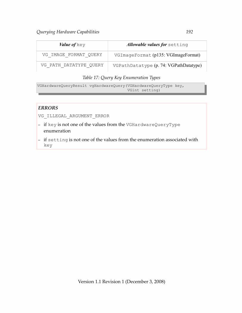
Querying Hardware Capabilities 192
Value of key Allowable values for settingVG_IMAGE_FORMAT_QUERY VGImageFormat (p135: VGImageFormat)
VG_PATH_DATATYPE_QUERY VGPathDatatype (p. 74: VGPathDatatype)
Table 17: Query Key Enumeration TypesVGHardwareQueryResult vgHardwareQuery(VGHardwareQueryType key, VGint setting)
ERRORSVG_ILLEGAL_ARGUMENT_ERROR– if key is not one of the values from the VGHardwareQueryType
enumeration
– if setting is not one of the values from the enumeration associated with key
Version 1.1 Revision 1 (December 3, 2008)
Extending the API 193
15 Extending the APIOpenVG is designed to be extended using an extension mechanism modeled after that of OpenGL and OpenGL ES. An extension may define new state elements, new datatypes, new values for existing parameter types, and new functions. Use of these features may alter the operation of the rendering pipeline. However, an extension must have no effect on programs that do not enable any of its features.
15.1 Extension Naming ConventionsAn OpenVG extension is named by a string of the form OVG_type_name, where type is either the string EXT or a vendor-specific string and name is a name assigned by the extension author. A letter X added to the end of type indicates that the extension is experimental.
Values (e.g., enumerated values or preprocessor #defines) defined by an extension carry the suffix _type. Functions and datatypes carry the suffix type without a separating underscore.
The openvg.h header file will define a preprocessor macro with the name OVG_type_name and a value of 1 for each supported extension.
15.2 The Extension RegistryKhronos, or its designee, will maintain a publicly-accessible registry of extensions. This registry will contain, for each extension, at least the following information:
• The name of the extension in the form OVG_type_name• An email address of a contact person• A list of dependencies on other extensions• A statement on the IP status of the extension• An overview of the scope and semantics of the extension• New functions defined by the extension• New datatypes defined by the extension • New values to be added to existing enumerated datatypes• Additions and changes to the OpenVG specification• New errors generated by functions affected by the extension• New state defined by the extension• Authorship information and revision history
15.3 Using ExtensionsExtensions may be detected statically, by means of preprocessor symbols, or
Version 1.1 Revision 1 (December 3, 2008)
Extending the API 194
dynamically, by means of the vgGetString function. Extension functions may be included in application code statically by placing appropriate “#ifdef” directives around functions that require the presence of a particular extension, and may also be accessed dynamically through function pointers returned by eglGetProcAddress or by other platform-specific means.
15.3.1 Accessing Extensions StaticallyThe extensions defined by a given platform are defined in the openvg.h header file, or in header files automatically included by openvg.h. In order to write applications that run on platforms with and without a given extension, conditional compilation based on the presence of the extension’s preprocessor macro may be used:#ifdef OVG_EXT_my_extension vgMyExtensionFuncEXT(...);#endif
15.3.2 Accessing Extensions DynamicallyOpenVG contains a mechanism for applications to access information about the runtime platform, and to access extensions that may not have been present when the application was compiled.
VGStringIDtypedef enum { VG_VENDOR = 0x2300, VG_RENDERER = 0x2301, VG_VERSION = 0x2302, VG_EXTENSIONS = 0x2303} VGStringID;
vgGetStringThe vgGetString function returns information about the OpenVG implementation, including extension information. The values returned may vary according to the display (e.g., the EGLDisplay when using EGL) associated with the current context. If no context is current, vgGetString returns NULL.
The combination of VG_VENDOR and VG_RENDERER may be used together as a platform identifier by applications that wish to recognize a particular platform and adjust their algorithms based on prior knowledge of platform bugs and performance characteristics .
If name is VG_VENDOR, the name of company responsible for this OpenVG
Version 1.1 Revision 1 (December 3, 2008)
Extending the API 195
implementation is returned. This name does not change from release to release.
If name is VG_RENDERER, the name of the renderer is returned. This name is typically specific to a particular configuration of a hardware platform, and does not change from release to release.
If name is VG_VERSION, the version number of the specification implemented by the renderer is returned as a string in the form major_number.minor_number. For this specification, “1.1” is returned.
If name is VG_EXTENSIONS, a space-separated list of supported extensions to OpenVG is returned.
For other values of name, NULL is returned.const VGubyte * vgGetString(VGStringID name)
eglGetProcAddressFunctions defined by an extension may be accessed by means of a function pointer obtained from the EGL function eglGetProcAddress. If EGL is not present, the platform may define an alternate method of obtaining extension function pointers.
15.4 Creating ExtensionsAny vendor may define a vendor-specific extension. Each vendor should apply to Khronos to obtain a vendor string and any numerical token values required by the extension.
An OpenVG extension may be deemed a shared extension if two or more vendors agree in good faith to ship an extension, or the Khronos OpenVG working group determines that it is in the best interest of its members that the extension be shared. A shared extension may be adopted (with appropriate naming changes) into a subsequent release of the OpenVG specification.
Version 1.1 Revision 1 (December 3, 2008)
API Conformance 196
16 API ConformanceAll OpenVG implementations are required to pass a conformance test suite. The exact details of the conformance testing process are available in a separate document. This chapter outlines the OpenVG conformance test philosophy and provides information that may be useful in order to ensure conformant implementations.
16.1 Conformance Test PrinciplesThe OpenVG specification attempts to strike a balance between the needs of implementers and application developers. While application developers desire a stable platform that delivers predictable results, they also wish to avoid reduced performance due to an excessively strict API definition. By allowing some flexibility in how the API is implemented, implementations may be optimized for a wide variety of platforms with varying price, performance, and power characteristics. The purpose of conformance testing is to ensure that implementations with different internal approaches produce similar results.
16.1.1 Window System IndependenceBecause OpenVG does not mandate a specific window system or display management API, the conformance test suite will isolate all display dependencies in a module that may be customized for each platform. An EGL-based implementation of this module will be provided, but implementers are free to replace this implementation with one that is specific to their platform.
16.1.2 Antialiasing Algorithm IndependenceIt is anticipated that a wide variety of antialiasing approaches will be used in the marketplace. Low-cost antialiasing remains a research topic, and new algorithms continue to emerge. The conformance suite must allow for this variation, while not allowing differences in antialiasing to cover up inadequacies in other portions of the implementation such as matrix transformation or curve subdivision.
16.1.3 On-Device and Off-Device TestingCertain conformance tests require only a small memory footprint, and may be run directly on the target device. Other tests operate by generating an image, which must be copied off-device. A desktop tool is used to compare the generated images against a set of reference images.
Version 1.1 Revision 1 (December 3, 2008)
API Conformance 197
16.2 Types of Conformance TestsConformance tests fall into several classes, outlined below.
16.2.1 Pipeline TestsA set of tests will be provided that attempt to isolate each pipeline stage by means of suitable parameter settings. These tests will provide assurance that each stage is functioning correctly.
16.2.2 Self-Consistency TestsCertain portions of the API are required to produce exact results. For example, setting and retrieving API state, image, paint, and path parameters, setting and retrieving matrix values; error generation; and pixel copies are defined to have exact results. The conformance suite will provide strict checking for these behaviors.
16.2.3 Matrix TestsThe conformance suite will exercise various matrix operations and compare the results against double-precision values. The comparison threshold will be set to exclude implementations with insufficient internal precision.
16.2.4 Interior/Exterior TestsAlthough antialiasing may have varying effects on shape boundaries, the portions of the interior and exterior of shapes that are more than 1 ½ pixels from a geometric boundary should not be affected by that boundary. If a shape is drawn using color paint, a set of known interior and exterior pixels may be tested for equality with the paint color.
16.2.5 Positional InvarianceDrawing should not depend on absolute screen coordinates, except for minor differences due to spatially-variant sampling and dither patterns when copying to the screen. The conformance suite will include tests that verify the positional independence of drawing.
16.2.6 Image Comparison TestsTo allow for controlled variation, the conformance suite will provide a set of rendering code fragments, along with reference images that have been generated using a high-quality implementation. Implementation-generated images will be compared to these reference images using a fuzzy comparison system. This approach is intended to allow for small differences in the accuracy of geometry and color processing and antialiasing,
Version 1.1 Revision 1 (December 3, 2008)
API Conformance 198
while rejecting larger differences that are considered visually unacceptable. The comparison threshold will be determined by generating images with a variety of acceptable and unacceptable differences and comparing them against the reference image.
Version 1.1 Revision 1 (December 3, 2008)
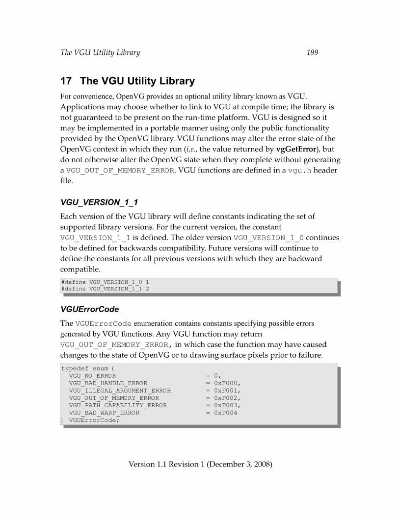
The VGU Utility Library 199
17 The VGU Utility LibraryFor convenience, OpenVG provides an optional utility library known as VGU. Applications may choose whether to link to VGU at compile time; the library is not guaranteed to be present on the run-time platform. VGU is designed so it may be implemented in a portable manner using only the public functionality provided by the OpenVG library. VGU functions may alter the error state of the OpenVG context in which they run (i.e., the value returned by vgGetError), but do not otherwise alter the OpenVG state when they complete without generating a VGU_OUT_OF_MEMORY_ERROR. VGU functions are defined in a vgu.h header file.
VGU_VERSION_1_1Each version of the VGU library will define constants indicating the set of supported library versions. For the current version, the constant VGU_VERSION_1_1 is defined. The older version VGU_VERSION_1_0 continues to be defined for backwards compatibility. Future versions will continue to define the constants for all previous versions with which they are backward compatible.#define VGU_VERSION_1_0 1#define VGU_VERSION_1_1 2
VGUErrorCodeThe VGUErrorCode enumeration contains constants specifying possible errors generated by VGU functions. Any VGU function may return VGU_OUT_OF_MEMORY_ERROR, in which case the function may have caused changes to the state of OpenVG or to drawing surface pixels prior to failure.typedef enum { VGU_NO_ERROR = 0, VGU_BAD_HANDLE_ERROR = 0xF000, VGU_ILLEGAL_ARGUMENT_ERROR = 0xF001, VGU_OUT_OF_MEMORY_ERROR = 0xF002, VGU_PATH_CAPABILITY_ERROR = 0xF003, VGU_BAD_WARP_ERROR = 0xF004} VGUErrorCode;
Version 1.1 Revision 1 (December 3, 2008)
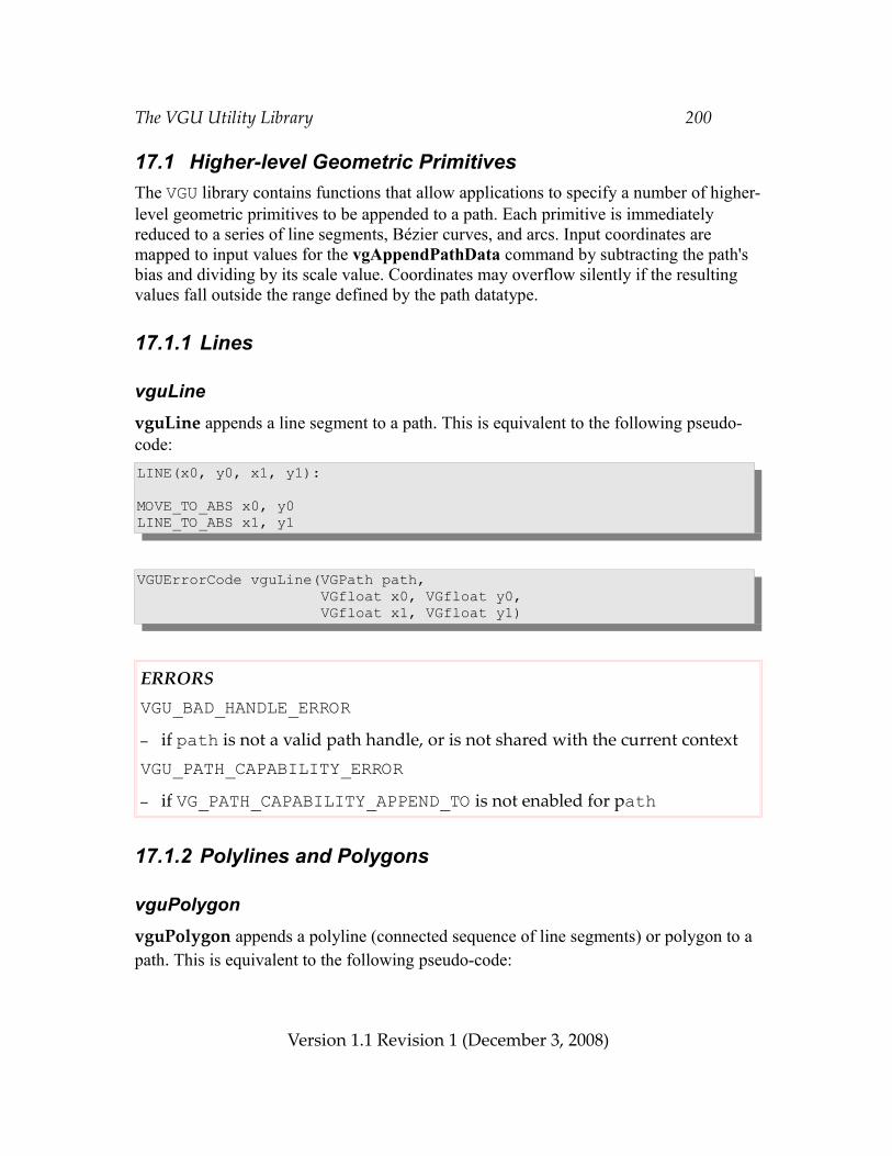
The VGU Utility Library 200
17.1 Higher-level Geometric PrimitivesThe VGU library contains functions that allow applications to specify a number of higher-level geometric primitives to be appended to a path. Each primitive is immediately reduced to a series of line segments, Bézier curves, and arcs. Input coordinates are mapped to input values for the vgAppendPathData command by subtracting the path's bias and dividing by its scale value. Coordinates may overflow silently if the resulting values fall outside the range defined by the path datatype.
17.1.1 Lines
vguLinevguLine appends a line segment to a path. This is equivalent to the following pseudo-code:LINE(x0, y0, x1, y1):
MOVE_TO_ABS x0, y0LINE_TO_ABS x1, y1
VGUErrorCode vguLine(VGPath path, VGfloat x0, VGfloat y0, VGfloat x1, VGfloat y1)
ERRORSVGU_BAD_HANDLE_ERROR– if path is not a valid path handle, or is not shared with the current contextVGU_PATH_CAPABILITY_ERROR– if VG_PATH_CAPABILITY_APPEND_TO is not enabled for path
17.1.2 Polylines and Polygons
vguPolygonvguPolygon appends a polyline (connected sequence of line segments) or polygon to a path. This is equivalent to the following pseudo-code:
Version 1.1 Revision 1 (December 3, 2008)
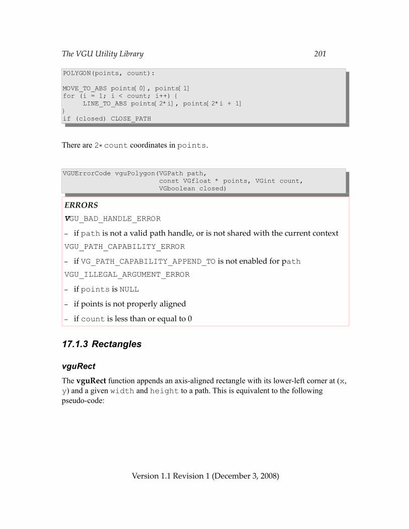
The VGU Utility Library 201
POLYGON(points, count):
MOVE_TO_ABS points[0], points[1]for (i = 1; i < count; i++) { LINE_TO_ABS points[2*i], points[2*i + 1]}if (closed) CLOSE_PATH
There are 2*count coordinates in points.
VGUErrorCode vguPolygon(VGPath path, const VGfloat * points, VGint count, VGboolean closed)
ERRORSVGU_BAD_HANDLE_ERROR– if path is not a valid path handle, or is not shared with the current contextVGU_PATH_CAPABILITY_ERROR– if VG_PATH_CAPABILITY_APPEND_TO is not enabled for pathVGU_ILLEGAL_ARGUMENT_ERROR– if points is NULL– if points is not properly aligned
– if count is less than or equal to 0
17.1.3 Rectangles
vguRectThe vguRect function appends an axis-aligned rectangle with its lower-left corner at (x, y) and a given width and height to a path. This is equivalent to the following pseudo-code:
Version 1.1 Revision 1 (December 3, 2008)
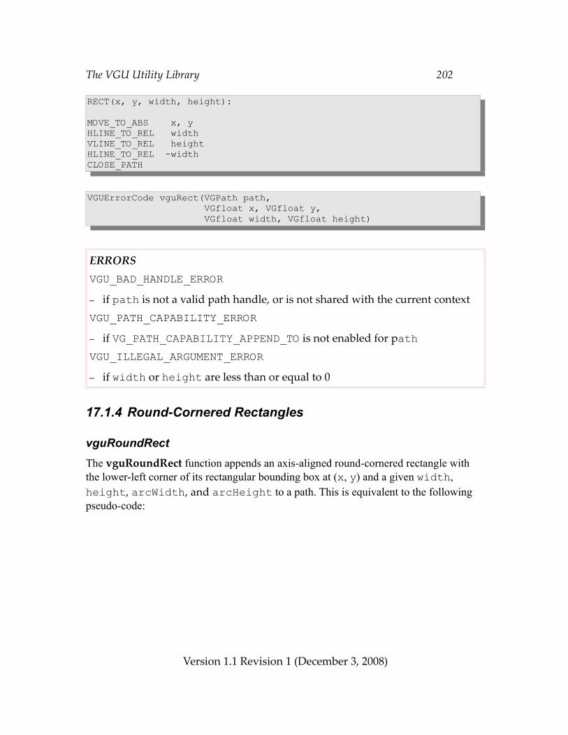
The VGU Utility Library 202
RECT(x, y, width, height):
MOVE_TO_ABS x, yHLINE_TO_REL widthVLINE_TO_REL heightHLINE_TO_REL -widthCLOSE_PATH
VGUErrorCode vguRect(VGPath path, VGfloat x, VGfloat y, VGfloat width, VGfloat height)
ERRORSVGU_BAD_HANDLE_ERROR– if path is not a valid path handle, or is not shared with the current contextVGU_PATH_CAPABILITY_ERROR– if VG_PATH_CAPABILITY_APPEND_TO is not enabled for pathVGU_ILLEGAL_ARGUMENT_ERROR– if width or height are less than or equal to 0
17.1.4 Round-Cornered Rectangles
vguRoundRectThe vguRoundRect function appends an axis-aligned round-cornered rectangle with the lower-left corner of its rectangular bounding box at (x, y) and a given width, height, arcWidth, and arcHeight to a path. This is equivalent to the following pseudo-code:
Version 1.1 Revision 1 (December 3, 2008)
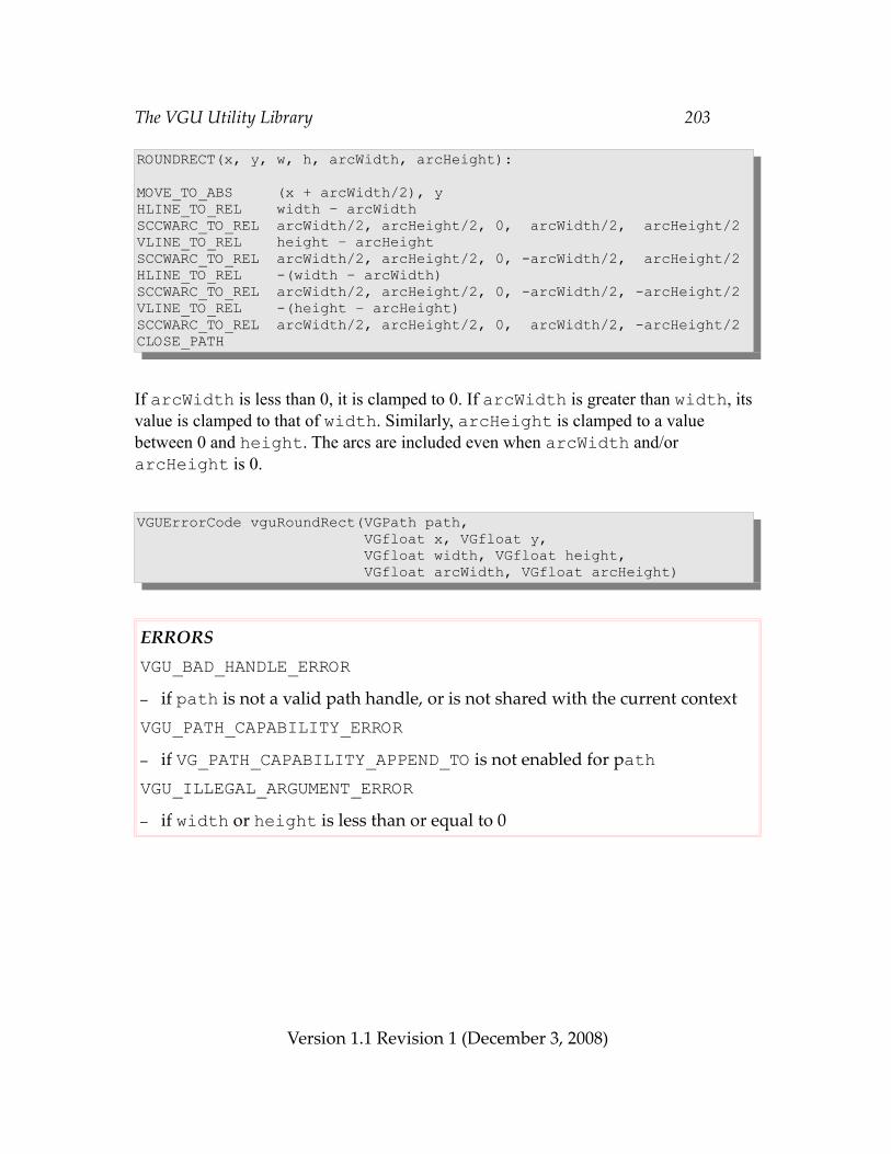
The VGU Utility Library 203
ROUNDRECT(x, y, w, h, arcWidth, arcHeight):
MOVE_TO_ABS (x + arcWidth/2), yHLINE_TO_REL width – arcWidthSCCWARC_TO_REL arcWidth/2, arcHeight/2, 0, arcWidth/2, arcHeight/2VLINE_TO_REL height – arcHeightSCCWARC_TO_REL arcWidth/2, arcHeight/2, 0, -arcWidth/2, arcHeight/2HLINE_TO_REL -(width – arcWidth)SCCWARC_TO_REL arcWidth/2, arcHeight/2, 0, -arcWidth/2, -arcHeight/2VLINE_TO_REL -(height – arcHeight)SCCWARC_TO_REL arcWidth/2, arcHeight/2, 0, arcWidth/2, -arcHeight/2CLOSE_PATH
If arcWidth is less than 0, it is clamped to 0. If arcWidth is greater than width, its value is clamped to that of width. Similarly, arcHeight is clamped to a value between 0 and height. The arcs are included even when arcWidth and/or arcHeight is 0.
VGUErrorCode vguRoundRect(VGPath path, VGfloat x, VGfloat y, VGfloat width, VGfloat height, VGfloat arcWidth, VGfloat arcHeight)
ERRORSVGU_BAD_HANDLE_ERROR– if path is not a valid path handle, or is not shared with the current contextVGU_PATH_CAPABILITY_ERROR– if VG_PATH_CAPABILITY_APPEND_TO is not enabled for pathVGU_ILLEGAL_ARGUMENT_ERROR– if width or height is less than or equal to 0
Version 1.1 Revision 1 (December 3, 2008)
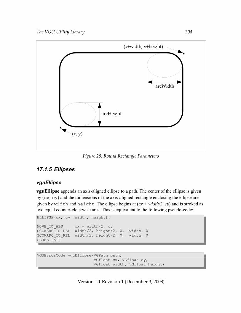
The VGU Utility Library 204
Figure 28: Round Rectangle Parameters
17.1.5 Ellipses
vguEllipsevguEllipse appends an axis-aligned ellipse to a path. The center of the ellipse is given by (cx, cy) and the dimensions of the axis-aligned rectangle enclosing the ellipse are given by width and height. The ellipse begins at (cx + width/2, cy) and is stroked as two equal counter-clockwise arcs. This is equivalent to the following pseudo-code:ELLIPSE(cx, cy, width, height):
MOVE_TO_ABS cx + width/2, cySCCWARC_TO_REL width/2, height/2, 0, -width, 0SCCWARC_TO_REL width/2, height/2, 0, width, 0CLOSE_PATH
VGUErrorCode vguEllipse(VGPath path, VGfloat cx, VGfloat cy, VGfloat width, VGfloat height)
Version 1.1 Revision 1 (December 3, 2008)
(x, y)
(x+width, y+height)
arcWidth
arcHeight
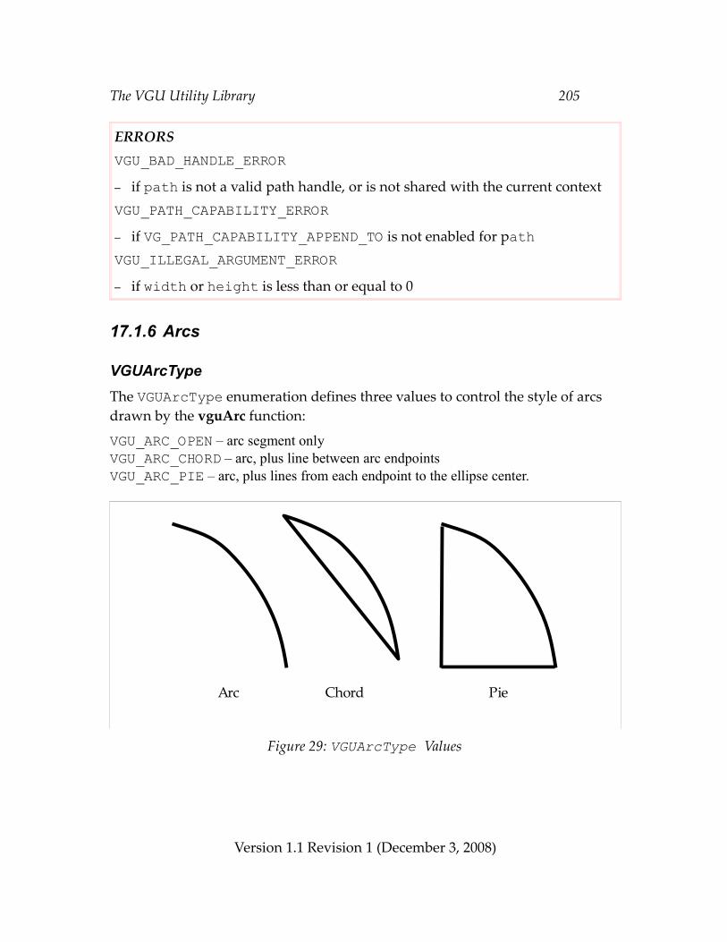
The VGU Utility Library 205
ERRORSVGU_BAD_HANDLE_ERROR– if path is not a valid path handle, or is not shared with the current contextVGU_PATH_CAPABILITY_ERROR– if VG_PATH_CAPABILITY_APPEND_TO is not enabled for pathVGU_ILLEGAL_ARGUMENT_ERROR– if width or height is less than or equal to 0
17.1.6 Arcs
VGUArcTypeThe VGUArcType enumeration defines three values to control the style of arcs drawn by the vguArc function:
VGU_ARC_OPEN – arc segment onlyVGU_ARC_CHORD – arc, plus line between arc endpointsVGU_ARC_PIE – arc, plus lines from each endpoint to the ellipse center.
Figure 29: VGUArcType Values
Version 1.1 Revision 1 (December 3, 2008)
Arc Chord Pie
The VGU Utility Library 206
vguArcvguArc appends an elliptical arc to a path, possibly along with one or two line segments, according to the arcType parameter. The startAngle and angleExtent parameters are given in degrees, proceeding counter-clockwise from the positive X axis. The arc is defined on the unit circle, then scaled by the width and height of the ellipse; thus, the starting point of the arc has coordinates (x + cos(startAngle)*w/2, y + sin(startAngle)*h/2) and the ending point has coordinates (x + cos(startAngle + angleExtent)*w/2, y + sin(startAngle + angleExtent)*h/2).
If angleExtent is negative, the arc will proceed clockwise; if it is larger than 360 or smaller than -360, the arc will wrap around itself. The following pseudo-code illustrates the arc path generation:ARC(x, y, w, h, startAngle, angleExtent, arcType):
last = startAngle + angleExtentMOVE_TO_ABS x+cos(startAngle)*w/2, y+sin(startAngle)*h/2if (angleExtent > 0) { angle = startAngle + 180 while (angle < last) { SCCWARC_TO_ABS w/2, h/2, 0, x+cos(angle)*w/2, y+sin(angle)*h/2 angle += 180 } SCCWARC_TO_ABS w/2, h/2, 0, x+cos(last)*w/2, y+sin(last)*h/2} else { angle = startAngle – 180 while (angle > last) { SCWARC_TO_ABS w/2, h/2, 0, x+cos(angle)*w/2, y+sin(angle)*h/2 angle -= 180 } SCWARC_TO_ABS w/2, h/2, 0, x+cos(last)*w/2, y+sin(last)*h/2}
if arcType == VGU_ARC_PIE LINE_TO_ABS x, yif arcType == VGU_ARC_PIE || arcType == VGU_ARC_CHORD CLOSE_PATH
VGUErrorCode vguArc(VGPath path, VGfloat x, VGfloat y, VGfloat width, VGfloat height, VGfloat startAngle, VGfloat angleExtent, VGUArcType arcType)
Version 1.1 Revision 1 (December 3, 2008)
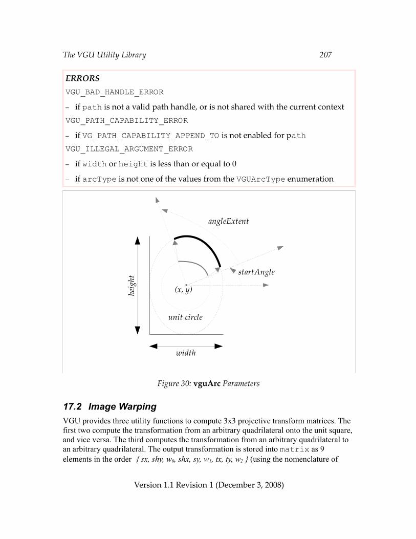
The VGU Utility Library 207
ERRORSVGU_BAD_HANDLE_ERROR– if path is not a valid path handle, or is not shared with the current contextVGU_PATH_CAPABILITY_ERROR– if VG_PATH_CAPABILITY_APPEND_TO is not enabled for pathVGU_ILLEGAL_ARGUMENT_ERROR– if width or height is less than or equal to 0
– if arcType is not one of the values from the VGUArcType enumeration
Figure 30: vguArc Parameters
17.2 Image WarpingVGU provides three utility functions to compute 3x3 projective transform matrices. The first two compute the transformation from an arbitrary quadrilateral onto the unit square, and vice versa. The third computes the transformation from an arbitrary quadrilateral to an arbitrary quadrilateral. The output transformation is stored into matrix as 9 elements in the order { sx, shy, w0, shx, sy, w1, tx, ty, w2 } (using the nomenclature of
Version 1.1 Revision 1 (December 3, 2008)
(x, y)
startAngle
angleExtent
heig
ht
width
unit circle
The VGU Utility Library 208
Section 6.3).
In all cases, if there is no projective mapping that satisfies the given constraints, or the mapping would be degenerate (i.e., non-invertible), VGU_BAD_WARP_ERROR is returned and matrix is unchanged.
Formulas for computing projective warps may be found in [HECK89] and [WOLB90].
vguComputeWarpQuadToSquareThe vguComputeWarpQuadToSquare function sets the entries of matrix to a projective transformation that maps the point (sx0, sy0) to (0, 0); (sx1, sy1) to (1, 0); (sx2, sy2) to (0, 1); and (sx3, sy3) to (1, 1). If no non-degenerate matrix satisfies the constraints, VGU_BAD_WARP_ERROR is returned and matrix is unchanged.VGUErrorCode vguComputeWarpQuadToSquare(VGfloat sx0, VGfloat sy0, VGfloat sx1, VGfloat sy1, VGfloat sx2, VGfloat sy2, VGfloat sx3, VGfloat sy3, VGfloat * matrix)
ERRORSVGU_ILLEGAL_ARGUMENT_ERROR– if matrix is NULL– if matrix is not properly alignedVGU_BAD_WARP_ERROR– if no non-degenerate transformation satisfies the constraints
vguComputeWarpSquareToQuadThe vguComputeWarpSquareToQuad function sets the entries of matrix to a projective transformation that maps the point (0, 0) to (dx0, dy0); (1, 0) to (dx1, dy1); (0, 1) to (dx2, dy2); and (1, 1) to (dx3, dy3). If no non-degenerate matrix satisfies the constraints, VGU_BAD_WARP_ERROR is returned and matrix is unchanged.VGUErrorCode vguComputeWarpSquareToQuad(VGfloat dx0, VGfloat dy0, VGfloat dx1, VGfloat dy1, VGfloat dx2, VGfloat dy2, VGfloat dx3, VGfloat dy3, VGfloat * matrix)
Version 1.1 Revision 1 (December 3, 2008)
The VGU Utility Library 209
ERRORSVGU_ILLEGAL_ARGUMENT_ERROR– if matrix is NULL– if matrix is not properly alignedVGU_BAD_WARP_ERROR– if no non-degenerate transformation satisfies the constraints
vguComputeWarpQuadToQuadThe vguComputeWarpQuadToQuad function sets the entries of matrix to a projective transformation that maps the point (sx0, sy0) to (dx0, dy0); (sx1, sy1) to (dx1, dy1); (sx2, sy2) to (dx2, dy2); and (sx3, sy3) to (dx3, dy3). If no non-degenerate matrix satisfies the constraints, VGU_BAD_WARP_ERROR is returned and matrix is unchanged.VGUErrorCode vguComputeWarpQuadToQuad(VGfloat dx0, VGfloat dy0, VGfloat dx1, VGfloat dy1, VGfloat dx2, VGfloat dy2, VGfloat dx3, VGfloat dy3, VGfloat sx0, VGfloat sy0, VGfloat sx1, VGfloat sy1, VGfloat sx2, VGfloat sy2, VGfloat sx3, VGfloat sy3, VGfloat * matrix)
ERRORSVGU_ILLEGAL_ARGUMENT_ERROR– if matrix is NULL– if matrix is not properly alignedVGU_BAD_WARP_ERROR– if no non-degenerate transformation satisfies the constraints
Version 1.1 Revision 1 (December 3, 2008)
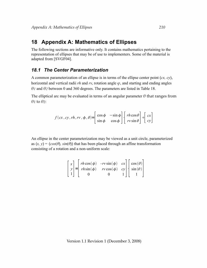
Appendix A: Mathematics of Ellipses 210
18 Appendix A: Mathematics of EllipsesThe following sections are informative only. It contains mathematics pertaining to the representation of ellipses that may be of use to implementers. Some of the material is adapted from [SVGF04].
18.1 The Center ParameterizationA common parameterization of an ellipse is in terms of the ellipse center point (cx, cy), horizontal and vertical radii rh and rv, rotation angle ϕ, and starting and ending angles θ1 and θ2 between 0 and 360 degrees. The parameters are listed in Table 18.
The elliptical arc may be evaluated in terms of an angular parameter θ that ranges from θ1 to θ2:
An ellipse in the center parameterization may be viewed as a unit circle, parameterized as (x, y) = (cos(θ), sin(θ)) that has been placed through an affine transformation consisting of a rotation and a non-uniform scale:
Version 1.1 Revision 1 (December 3, 2008)
f cx , cy , rh , rv , ,=[ cos −sinsin cos ]⋅[ rh cos
rv sin][ cxcy]
[ xy1]=[ rh cos -rv sin cx
rhsin rv cos cy0 0 1 ]⋅[ cos
sin 1 ]
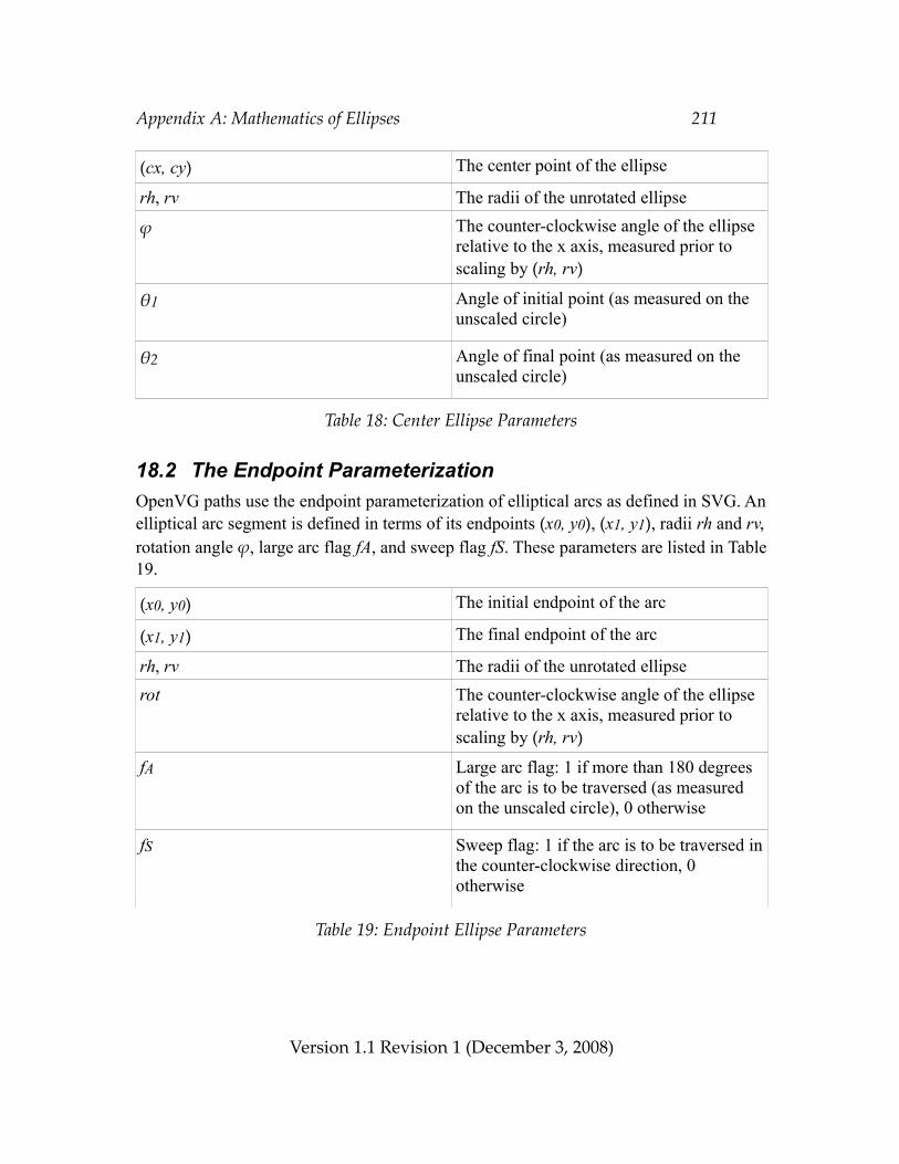
Appendix A: Mathematics of Ellipses 211
(cx, cy) The center point of the ellipse
rh, rv The radii of the unrotated ellipse
ϕ The counter-clockwise angle of the ellipse relative to the x axis, measured prior to scaling by (rh, rv)
θ1 Angle of initial point (as measured on the unscaled circle)
θ2 Angle of final point (as measured on the unscaled circle)
Table 18: Center Ellipse Parameters
18.2 The Endpoint ParameterizationOpenVG paths use the endpoint parameterization of elliptical arcs as defined in SVG. An elliptical arc segment is defined in terms of its endpoints (x0, y0), (x1, y1), radii rh and rv, rotation angle ϕ, large arc flag fA, and sweep flag fS. These parameters are listed in Table19.
(x0, y0) The initial endpoint of the arc
(x1, y1) The final endpoint of the arc
rh, rv The radii of the unrotated ellipserot The counter-clockwise angle of the ellipse
relative to the x axis, measured prior to scaling by (rh, rv)
fA Large arc flag: 1 if more than 180 degrees of the arc is to be traversed (as measured on the unscaled circle), 0 otherwise
fS Sweep flag: 1 if the arc is to be traversed in the counter-clockwise direction, 0 otherwise
Table 19: Endpoint Ellipse Parameters
Version 1.1 Revision 1 (December 3, 2008)
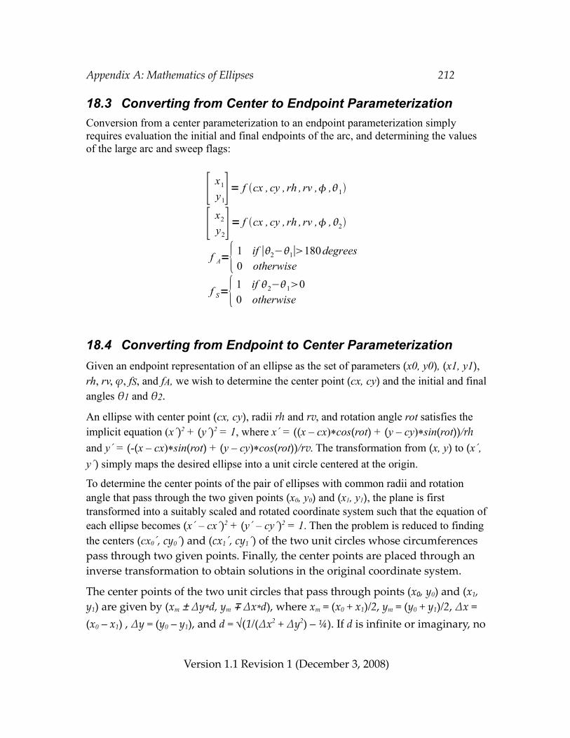
Appendix A: Mathematics of Ellipses 212
18.3 Converting from Center to Endpoint ParameterizationConversion from a center parameterization to an endpoint parameterization simply requires evaluation the initial and final endpoints of the arc, and determining the values of the large arc and sweep flags:
18.4 Converting from Endpoint to Center ParameterizationGiven an endpoint representation of an ellipse as the set of parameters (x0, y0), (x1, y1), rh, rv, ϕ, fS, and fA, we wish to determine the center point (cx, cy) and the initial and final angles θ1 and θ2.
An ellipse with center point (cx, cy), radii rh and rv, and rotation angle rot satisfies the implicit equation (x´)2 + (y´)2 = 1, where x´ = ((x – cx)*cos(rot) + (y – cy)*sin(rot))/rh and y´ = (-(x – cx)*sin(rot) + (y – cy)*cos(rot))/rv. The transformation from (x, y) to (x´, y´) simply maps the desired ellipse into a unit circle centered at the origin.
To determine the center points of the pair of ellipses with common radii and rotation angle that pass through the two given points (x0, y0) and (x1, y1), the plane is first transformed into a suitably scaled and rotated coordinate system such that the equation of each ellipse becomes (x´ – cx´)2 + (y´ – cy´)2 = 1. Then the problem is reduced to finding the centers (cx0´, cy0´) and (cx1´, cy1´) of the two unit circles whose circumferences pass through two given points. Finally, the center points are placed through an inverse transformation to obtain solutions in the original coordinate system.
The center points of the two unit circles that pass through points (x0, y0) and (x1, y1) are given by (xm ± ∆y*d, ym ∓ ∆x*d), where xm = (x0 + x1)/2, ym = (y0 + y1)/2, ∆x = (x0 – x1) , ∆y = (y0 – y1), and d = √(1/(∆x2 + ∆y2) – ¼). If d is infinite or imaginary, no
Version 1.1 Revision 1 (December 3, 2008)
[ x1
y1]= f cx , cy , rh , rv , ,1
[ x2
y2]= f cx , cy , rh , rv , ,2
f A={ 1 if ∣2−1∣180degrees0 otherwise
f S={ 1 if 2−100 otherwise
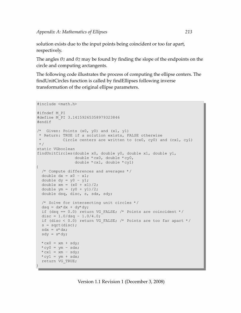
Appendix A: Mathematics of Ellipses 213
solution exists due to the input points being coincident or too far apart, respectively.
The angles θ1 and θ2 may be found by finding the slope of the endpoints on the circle and computing arctangents.
The following code illustrates the process of computing the ellipse centers. The findUnitCircles function is called by findEllipses following inverse transformation of the original ellipse parameters.
#include <math.h>
#ifndef M_PI#define M_PI 3.14159265358979323846#endif
/* Given: Points (x0, y0) and (x1, y1) * Return: TRUE if a solution exists, FALSE otherwise * Circle centers are written to (cx0, cy0) and (cx1, cy1) */static VGbooleanfindUnitCircles(double x0, double y0, double x1, double y1, double *cx0, double *cy0, double *cx1, double *cy1){ /* Compute differences and averages */ double dx = x0 – x1; double dy = y0 – y1; double xm = (x0 + x1)/2; double ym = (y0 + y1)/2; double dsq, disc, s, sdx, sdy;
/* Solve for intersecting unit circles */ dsq = dx*dx + dy*dy; if (dsq == 0.0) return VG_FALSE; /* Points are coincident */ disc = 1.0/dsq – 1.0/4.0; if (disc < 0.0) return VG_FALSE; /* Points are too far apart */ s = sqrt(disc); sdx = s*dx; sdy = s*dy;
*cx0 = xm + sdy; *cy0 = ym – sdx; *cx1 = xm – sdy; *cy1 = ym + sdx; return VG_TRUE;}
Version 1.1 Revision 1 (December 3, 2008)
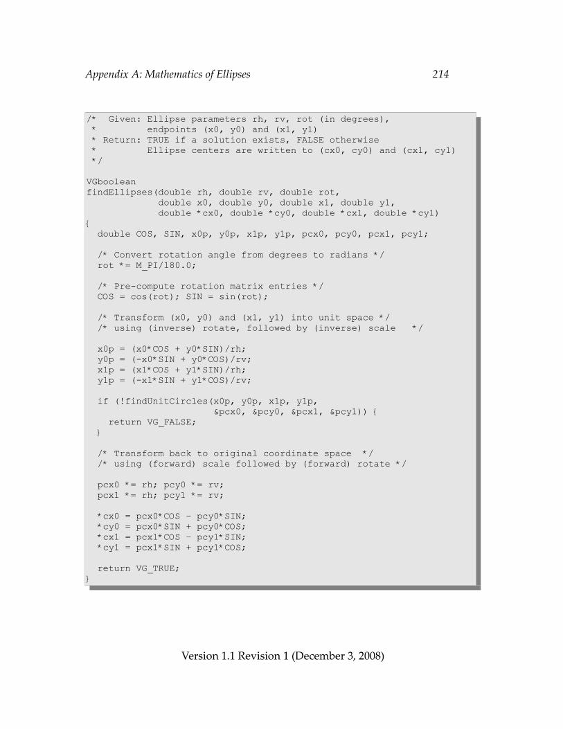
Appendix A: Mathematics of Ellipses 214
/* Given: Ellipse parameters rh, rv, rot (in degrees), * endpoints (x0, y0) and (x1, y1) * Return: TRUE if a solution exists, FALSE otherwise * Ellipse centers are written to (cx0, cy0) and (cx1, cy1) */
VGbooleanfindEllipses(double rh, double rv, double rot, double x0, double y0, double x1, double y1, double *cx0, double *cy0, double *cx1, double *cy1){ double COS, SIN, x0p, y0p, x1p, y1p, pcx0, pcy0, pcx1, pcy1;
/* Convert rotation angle from degrees to radians */ rot *= M_PI/180.0;
/* Pre-compute rotation matrix entries */ COS = cos(rot); SIN = sin(rot);
/* Transform (x0, y0) and (x1, y1) into unit space */ /* using (inverse) rotate, followed by (inverse) scale */
x0p = (x0*COS + y0*SIN)/rh; y0p = (-x0*SIN + y0*COS)/rv; x1p = (x1*COS + y1*SIN)/rh; y1p = (-x1*SIN + y1*COS)/rv;
if (!findUnitCircles(x0p, y0p, x1p, y1p, &pcx0, &pcy0, &pcx1, &pcy1)) { return VG_FALSE; }
/* Transform back to original coordinate space */ /* using (forward) scale followed by (forward) rotate */
pcx0 *= rh; pcy0 *= rv; pcx1 *= rh; pcy1 *= rv;
*cx0 = pcx0*COS – pcy0*SIN; *cy0 = pcx0*SIN + pcy0*COS; *cx1 = pcx1*COS – pcy1*SIN; *cy1 = pcx1*SIN + pcy1*COS;
return VG_TRUE;}
Version 1.1 Revision 1 (December 3, 2008)
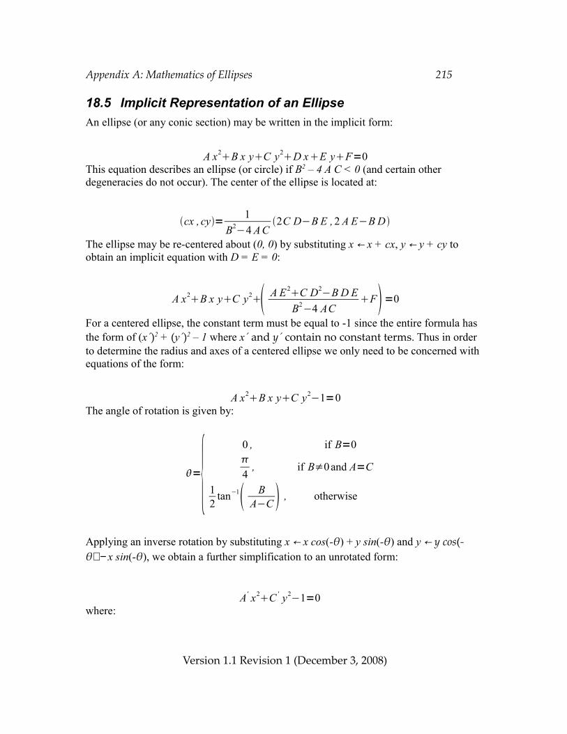
Appendix A: Mathematics of Ellipses 215
18.5 Implicit Representation of an EllipseAn ellipse (or any conic section) may be written in the implicit form:
This equation describes an ellipse (or circle) if B2 – 4 A C < 0 (and certain other degeneracies do not occur). The center of the ellipse is located at:
The ellipse may be re-centered about (0, 0) by substituting x ← x + cx, y ← y + cy to obtain an implicit equation with D = E = 0:
For a centered ellipse, the constant term must be equal to -1 since the entire formula has the form of (x´)2 + (y´)2 – 1 where x´ and y´ contain no constant terms. Thus in order to determine the radius and axes of a centered ellipse we only need to be concerned with equations of the form:
The angle of rotation is given by:
Applying an inverse rotation by substituting x ← x cos(-θ) + y sin(-θ) and y ← y cos(-θ) − x sin(-θ), we obtain a further simplification to an unrotated form:
where:
Version 1.1 Revision 1 (December 3, 2008)
A x2B x yC y2D xE yF=0
cx , cy= 1B2−4 A C
2C D−B E ,2 A E−B D
={0 , if B=04
, if B≠0 and A=C
12
tan−1 BA−C , otherwise
A x2B x yC y2 A E2C D2−B D EB2−4 AC
F=0
A x2B x yC y2−1=0
A' x2C ' y2−1=0
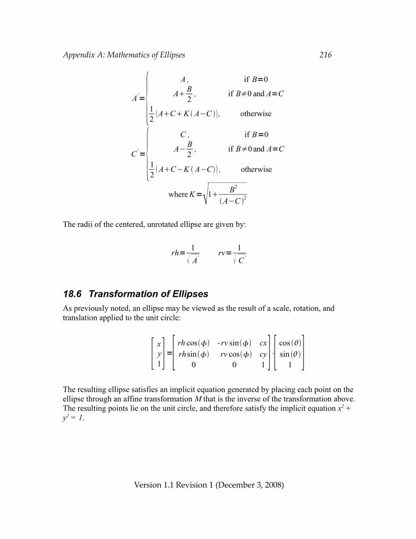
Appendix A: Mathematics of Ellipses 216
The radii of the centered, unrotated ellipse are given by:
18.6 Transformation of EllipsesAs previously noted, an ellipse may be viewed as the result of a scale, rotation, and translation applied to the unit circle:
The resulting ellipse satisfies an implicit equation generated by placing each point on the ellipse through an affine transformation M that is the inverse of the transformation above. The resulting points lie on the unit circle, and therefore satisfy the implicit equation x2 + y2 = 1.
Version 1.1 Revision 1 (December 3, 2008)
[ xy1]=[ rh cos -rv sin cx
rhsin rv cos cy0 0 1 ]⋅[ cos
sin 1 ]
rh= 1 A'
rv= 1 C '
A'={ A , if B=0
A B2
, if B≠0 and A=C
12 ACK A−C , otherwise
C '={C , if B=0
A− B2
, if B≠0and A=C
12 AC−K A−C , otherwise
where K=1 B2
A−C 2
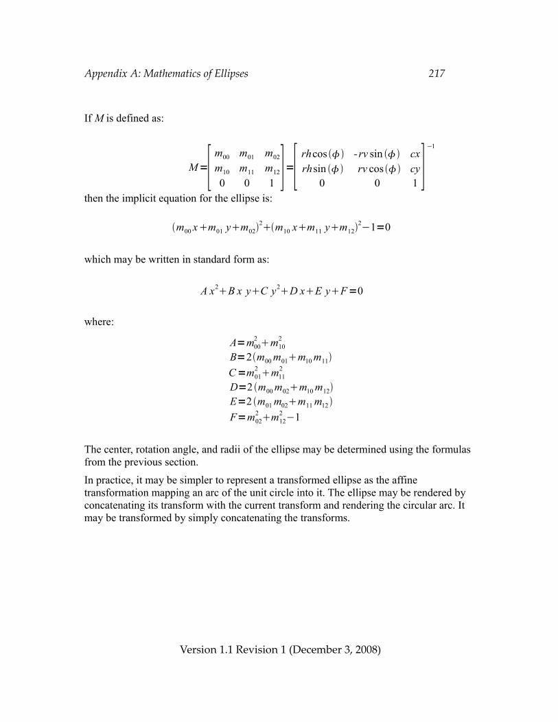
Appendix A: Mathematics of Ellipses 217
If M is defined as:
then the implicit equation for the ellipse is:
which may be written in standard form as:
where:
The center, rotation angle, and radii of the ellipse may be determined using the formulas from the previous section.
In practice, it may be simpler to represent a transformed ellipse as the affine transformation mapping an arc of the unit circle into it. The ellipse may be rendered by concatenating its transform with the current transform and rendering the circular arc. It may be transformed by simply concatenating the transforms.
Version 1.1 Revision 1 (December 3, 2008)
m00 xm01 ym022m10 xm11 ym12
2−1=0
A=m002 m10
2
B=2m00 m01m10 m11C=m01
2 m112
D=2 m00 m02m10 m12E=2 m01 m02m11 m12F=m02
2 m122 −1
M=[ m00 m01 m02
m10 m11 m12
0 0 1 ]=[ rhcos -rv sin cxrhsin rv cos cy
0 0 1 ]−1
A x2B x yC y2D xE yF=0
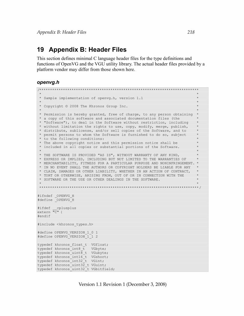
Appendix B: Header Files 218
19 Appendix B: Header FilesThis section defines minimal C language header files for the type definitions and functions of OpenVG and the VGU utility library. The actual header files provided by a platform vendor may differ from those shown here.
openvg.h/************************************************************************** * * * Sample implementation of openvg.h, version 1.1 * * * * Copyright © 2008 The Khronos Group Inc. * * * * Permission is hereby granted, free of charge, to any person obtaining * * a copy of this software and associated documentation files (the * * "Software"), to deal in the Software without restriction, including * * without limitation the rights to use, copy, modify, merge, publish, * * distribute, sublicense, and/or sell copies of the Software, and to * * permit persons to whom the Software is furnished to do so, subject * * to the following conditions: * * The above copyright notice and this permission notice shall be * * included in all copies or substantial portions of the Software. * * * * THE SOFTWARE IS PROVIDED "AS IS", WITHOUT WARRANTY OF ANY KIND, * * EXPRESS OR IMPLIED, INCLUDING BUT NOT LIMITED TO THE WARRANTIES OF * * MERCHANTABILITY, FITNESS FOR A PARTICULAR PURPOSE AND NONINFRINGEMENT. * * IN NO EVENT SHALL THE AUTHORS OR COPYRIGHT HOLDERS BE LIABLE FOR ANY * * CLAIM, DAMAGES OR OTHER LIABILITY, WHETHER IN AN ACTION OF CONTRACT, * * TORT OR OTHERWISE, ARISING FROM, OUT OF OR IN CONNECTION WITH THE * * SOFTWARE OR THE USE OR OTHER DEALINGS IN THE SOFTWARE. * * * **************************************************************************/
#ifndef _OPENVG_H#define _OPENVG_H
#ifdef __cplusplusextern "C" {#endif
#include <khronos_types.h>
#define OPENVG_VERSION_1_0 1#define OPENVG_VERSION_1_1 2
typedef khronos_float_t VGfloat;typedef khronos_int8_t VGbyte;typedef khronos_uint8_t VGubyte;typedef khronos_int16_t VGshort;typedef khronos_int32_t VGint;typedef khronos_uint32_t VGuint;typedef khronos_uint32_t VGbitfield;
Version 1.1 Revision 1 (December 3, 2008)
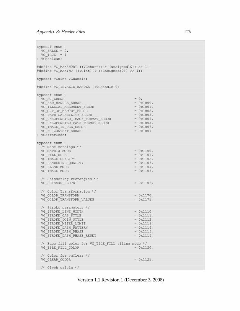
Appendix B: Header Files 219
typedef enum { VG_FALSE = 0, VG_TRUE = 1} VGboolean;
#define VG_MAXSHORT ((VGshort)((~((unsigned)0)) >> 1))#define VG_MAXINT ((VGint)((~((unsigned)0)) >> 1))
typedef VGuint VGHandle;
#define VG_INVALID_HANDLE ((VGHandle)0)
typedef enum { VG_NO_ERROR = 0, VG_BAD_HANDLE_ERROR = 0x1000, VG_ILLEGAL_ARGUMENT_ERROR = 0x1001, VG_OUT_OF_MEMORY_ERROR = 0x1002, VG_PATH_CAPABILITY_ERROR = 0x1003, VG_UNSUPPORTED_IMAGE_FORMAT_ERROR = 0x1004, VG_UNSUPPORTED_PATH_FORMAT_ERROR = 0x1005, VG_IMAGE_IN_USE_ERROR = 0x1006, VG_NO_CONTEXT_ERROR = 0x1007} VGErrorCode;
typedef enum { /* Mode settings */ VG_MATRIX_MODE = 0x1100, VG_FILL_RULE = 0x1101, VG_IMAGE_QUALITY = 0x1102, VG_RENDERING_QUALITY = 0x1103, VG_BLEND_MODE = 0x1104, VG_IMAGE_MODE = 0x1105,
/* Scissoring rectangles */ VG_SCISSOR_RECTS = 0x1106,
/* Color Transformation */ VG_COLOR_TRANSFORM = 0x1170, VG_COLOR_TRANSFORM_VALUES = 0x1171,
/* Stroke parameters */ VG_STROKE_LINE_WIDTH = 0x1110, VG_STROKE_CAP_STYLE = 0x1111, VG_STROKE_JOIN_STYLE = 0x1112, VG_STROKE_MITER_LIMIT = 0x1113, VG_STROKE_DASH_PATTERN = 0x1114, VG_STROKE_DASH_PHASE = 0x1115, VG_STROKE_DASH_PHASE_RESET = 0x1116,
/* Edge fill color for VG_TILE_FILL tiling mode */ VG_TILE_FILL_COLOR = 0x1120,
/* Color for vgClear */ VG_CLEAR_COLOR = 0x1121,
/* Glyph origin */
Version 1.1 Revision 1 (December 3, 2008)
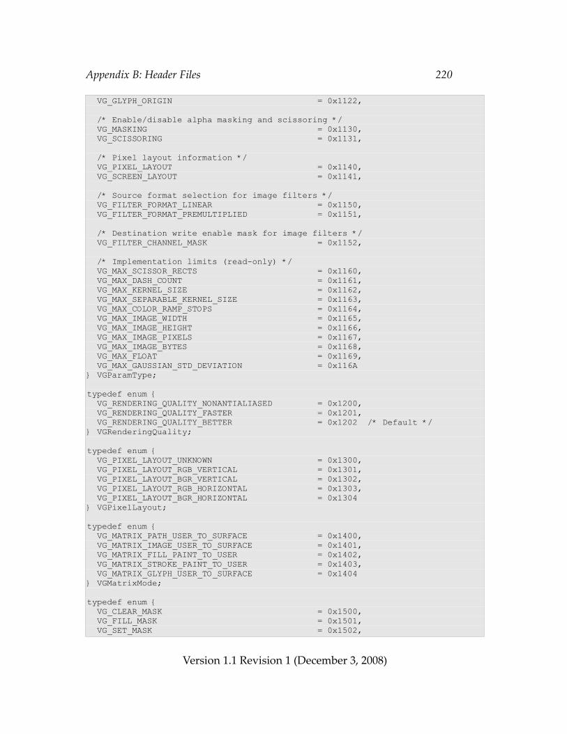
Appendix B: Header Files 220
VG_GLYPH_ORIGIN = 0x1122,
/* Enable/disable alpha masking and scissoring */ VG_MASKING = 0x1130, VG_SCISSORING = 0x1131,
/* Pixel layout information */ VG_PIXEL_LAYOUT = 0x1140, VG_SCREEN_LAYOUT = 0x1141,
/* Source format selection for image filters */ VG_FILTER_FORMAT_LINEAR = 0x1150, VG_FILTER_FORMAT_PREMULTIPLIED = 0x1151,
/* Destination write enable mask for image filters */ VG_FILTER_CHANNEL_MASK = 0x1152,
/* Implementation limits (read-only) */ VG_MAX_SCISSOR_RECTS = 0x1160, VG_MAX_DASH_COUNT = 0x1161, VG_MAX_KERNEL_SIZE = 0x1162, VG_MAX_SEPARABLE_KERNEL_SIZE = 0x1163, VG_MAX_COLOR_RAMP_STOPS = 0x1164, VG_MAX_IMAGE_WIDTH = 0x1165, VG_MAX_IMAGE_HEIGHT = 0x1166, VG_MAX_IMAGE_PIXELS = 0x1167, VG_MAX_IMAGE_BYTES = 0x1168, VG_MAX_FLOAT = 0x1169, VG_MAX_GAUSSIAN_STD_DEVIATION = 0x116A} VGParamType;
typedef enum { VG_RENDERING_QUALITY_NONANTIALIASED = 0x1200, VG_RENDERING_QUALITY_FASTER = 0x1201, VG_RENDERING_QUALITY_BETTER = 0x1202 /* Default */} VGRenderingQuality;
typedef enum { VG_PIXEL_LAYOUT_UNKNOWN = 0x1300, VG_PIXEL_LAYOUT_RGB_VERTICAL = 0x1301, VG_PIXEL_LAYOUT_BGR_VERTICAL = 0x1302, VG_PIXEL_LAYOUT_RGB_HORIZONTAL = 0x1303, VG_PIXEL_LAYOUT_BGR_HORIZONTAL = 0x1304} VGPixelLayout;
typedef enum { VG_MATRIX_PATH_USER_TO_SURFACE = 0x1400, VG_MATRIX_IMAGE_USER_TO_SURFACE = 0x1401, VG_MATRIX_FILL_PAINT_TO_USER = 0x1402, VG_MATRIX_STROKE_PAINT_TO_USER = 0x1403, VG_MATRIX_GLYPH_USER_TO_SURFACE = 0x1404} VGMatrixMode;
typedef enum { VG_CLEAR_MASK = 0x1500, VG_FILL_MASK = 0x1501, VG_SET_MASK = 0x1502,
Version 1.1 Revision 1 (December 3, 2008)
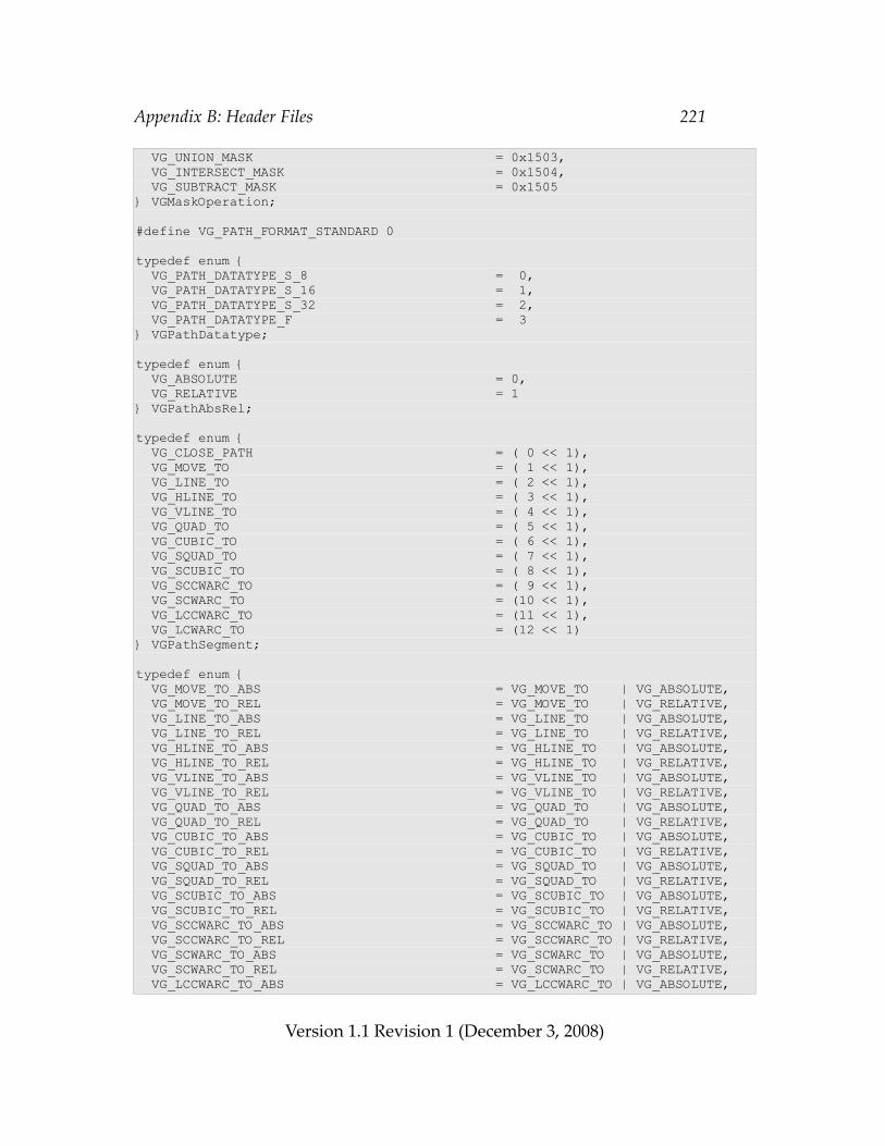
Appendix B: Header Files 221
VG_UNION_MASK = 0x1503, VG_INTERSECT_MASK = 0x1504, VG_SUBTRACT_MASK = 0x1505} VGMaskOperation;
#define VG_PATH_FORMAT_STANDARD 0
typedef enum { VG_PATH_DATATYPE_S_8 = 0, VG_PATH_DATATYPE_S_16 = 1, VG_PATH_DATATYPE_S_32 = 2, VG_PATH_DATATYPE_F = 3} VGPathDatatype;
typedef enum { VG_ABSOLUTE = 0, VG_RELATIVE = 1} VGPathAbsRel;
typedef enum { VG_CLOSE_PATH = ( 0 << 1), VG_MOVE_TO = ( 1 << 1), VG_LINE_TO = ( 2 << 1), VG_HLINE_TO = ( 3 << 1), VG_VLINE_TO = ( 4 << 1), VG_QUAD_TO = ( 5 << 1), VG_CUBIC_TO = ( 6 << 1), VG_SQUAD_TO = ( 7 << 1), VG_SCUBIC_TO = ( 8 << 1), VG_SCCWARC_TO = ( 9 << 1), VG_SCWARC_TO = (10 << 1), VG_LCCWARC_TO = (11 << 1), VG_LCWARC_TO = (12 << 1)} VGPathSegment;
typedef enum { VG_MOVE_TO_ABS = VG_MOVE_TO | VG_ABSOLUTE, VG_MOVE_TO_REL = VG_MOVE_TO | VG_RELATIVE, VG_LINE_TO_ABS = VG_LINE_TO | VG_ABSOLUTE, VG_LINE_TO_REL = VG_LINE_TO | VG_RELATIVE, VG_HLINE_TO_ABS = VG_HLINE_TO | VG_ABSOLUTE, VG_HLINE_TO_REL = VG_HLINE_TO | VG_RELATIVE, VG_VLINE_TO_ABS = VG_VLINE_TO | VG_ABSOLUTE, VG_VLINE_TO_REL = VG_VLINE_TO | VG_RELATIVE, VG_QUAD_TO_ABS = VG_QUAD_TO | VG_ABSOLUTE, VG_QUAD_TO_REL = VG_QUAD_TO | VG_RELATIVE, VG_CUBIC_TO_ABS = VG_CUBIC_TO | VG_ABSOLUTE, VG_CUBIC_TO_REL = VG_CUBIC_TO | VG_RELATIVE, VG_SQUAD_TO_ABS = VG_SQUAD_TO | VG_ABSOLUTE, VG_SQUAD_TO_REL = VG_SQUAD_TO | VG_RELATIVE, VG_SCUBIC_TO_ABS = VG_SCUBIC_TO | VG_ABSOLUTE, VG_SCUBIC_TO_REL = VG_SCUBIC_TO | VG_RELATIVE, VG_SCCWARC_TO_ABS = VG_SCCWARC_TO | VG_ABSOLUTE, VG_SCCWARC_TO_REL = VG_SCCWARC_TO | VG_RELATIVE, VG_SCWARC_TO_ABS = VG_SCWARC_TO | VG_ABSOLUTE, VG_SCWARC_TO_REL = VG_SCWARC_TO | VG_RELATIVE, VG_LCCWARC_TO_ABS = VG_LCCWARC_TO | VG_ABSOLUTE,
Version 1.1 Revision 1 (December 3, 2008)
Appendix B: Header Files 222
VG_LCCWARC_TO_REL = VG_LCCWARC_TO | VG_RELATIVE, VG_LCWARC_TO_ABS = VG_LCWARC_TO | VG_ABSOLUTE, VG_LCWARC_TO_REL = VG_LCWARC_TO | VG_RELATIVE} VGPathCommand;
typedef VGHandle VGPath;
typedef enum { VG_PATH_CAPABILITY_APPEND_FROM = (1 << 0), VG_PATH_CAPABILITY_APPEND_TO = (1 << 1), VG_PATH_CAPABILITY_MODIFY = (1 << 2), VG_PATH_CAPABILITY_TRANSFORM_FROM = (1 << 3), VG_PATH_CAPABILITY_TRANSFORM_TO = (1 << 4), VG_PATH_CAPABILITY_INTERPOLATE_FROM = (1 << 5), VG_PATH_CAPABILITY_INTERPOLATE_TO = (1 << 6), VG_PATH_CAPABILITY_PATH_LENGTH = (1 << 7), VG_PATH_CAPABILITY_POINT_ALONG_PATH = (1 << 8), VG_PATH_CAPABILITY_TANGENT_ALONG_PATH = (1 << 9), VG_PATH_CAPABILITY_PATH_BOUNDS = (1 << 10), VG_PATH_CAPABILITY_PATH_TRANSFORMED_BOUNDS = (1 << 11), VG_PATH_CAPABILITY_ALL = (1 << 12) - 1} VGPathCapabilities;
typedef enum { VG_PATH_FORMAT = 0x1600, VG_PATH_DATATYPE = 0x1601, VG_PATH_SCALE = 0x1602, VG_PATH_BIAS = 0x1603, VG_PATH_NUM_SEGMENTS = 0x1604, VG_PATH_NUM_COORDS = 0x1605} VGPathParamType;
typedef enum { VG_CAP_BUTT = 0x1700, VG_CAP_ROUND = 0x1701, VG_CAP_SQUARE = 0x1702} VGCapStyle;
typedef enum { VG_JOIN_MITER = 0x1800, VG_JOIN_ROUND = 0x1801, VG_JOIN_BEVEL = 0x1802} VGJoinStyle;
typedef enum { VG_EVEN_ODD = 0x1900, VG_NON_ZERO = 0x1901} VGFillRule;
typedef enum { VG_STROKE_PATH = (1 << 0), VG_FILL_PATH = (1 << 1)} VGPaintMode;
typedef VGHandle VGPaint;
typedef enum {
Version 1.1 Revision 1 (December 3, 2008)
Appendix B: Header Files 223
/* Color paint parameters */ VG_PAINT_TYPE = 0x1A00, VG_PAINT_COLOR = 0x1A01, VG_PAINT_COLOR_RAMP_SPREAD_MODE = 0x1A02, VG_PAINT_COLOR_RAMP_PREMULTIPLIED = 0x1A07, VG_PAINT_COLOR_RAMP_STOPS = 0x1A03,
/* Linear gradient paint parameters */ VG_PAINT_LINEAR_GRADIENT = 0x1A04,
/* Radial gradient paint parameters */ VG_PAINT_RADIAL_GRADIENT = 0x1A05,
/* Pattern paint parameters */ VG_PAINT_PATTERN_TILING_MODE = 0x1A06} VGPaintParamType;
typedef enum { VG_PAINT_TYPE_COLOR = 0x1B00, VG_PAINT_TYPE_LINEAR_GRADIENT = 0x1B01, VG_PAINT_TYPE_RADIAL_GRADIENT = 0x1B02, VG_PAINT_TYPE_PATTERN = 0x1B03} VGPaintType;
typedef enum { VG_COLOR_RAMP_SPREAD_PAD = 0x1C00, VG_COLOR_RAMP_SPREAD_REPEAT = 0x1C01, VG_COLOR_RAMP_SPREAD_REFLECT = 0x1C02} VGColorRampSpreadMode;
typedef enum { VG_TILE_FILL = 0x1D00, VG_TILE_PAD = 0x1D01, VG_TILE_REPEAT = 0x1D02, VG_TILE_REFLECT = 0x1D03} VGTilingMode;
typedef enum { /* RGB{A,X} channel ordering */ VG_sRGBX_8888 = 0, VG_sRGBA_8888 = 1, VG_sRGBA_8888_PRE = 2, VG_sRGB_565 = 3, VG_sRGBA_5551 = 4, VG_sRGBA_4444 = 5, VG_sL_8 = 6, VG_lRGBX_8888 = 7, VG_lRGBA_8888 = 8, VG_lRGBA_8888_PRE = 9, VG_lL_8 = 10, VG_A_8 = 11, VG_BW_1 = 12, VG_A_1 = 13, VG_A_4 = 14
/* {A,X}RGB channel ordering */ VG_sXRGB_8888 = 0 | (1 << 6),
Version 1.1 Revision 1 (December 3, 2008)
Appendix B: Header Files 224
VG_sARGB_8888 = 1 | (1 << 6), VG_sARGB_8888_PRE = 2 | (1 << 6), VG_sARGB_1555 = 4 | (1 << 6), VG_sARGB_4444 = 5 | (1 << 6), VG_lXRGB_8888 = 7 | (1 << 6), VG_lARGB_8888 = 8 | (1 << 6), VG_lARGB_8888_PRE = 9 | (1 << 6),
/* BGR{A,X} channel ordering */ VG_sBGRX_8888 = 0 | (1 << 7), VG_sBGRA_8888 = 1 | (1 << 7), VG_sBGRA_8888_PRE = 2 | (1 << 7), VG_sBGR_565 = 3 | (1 << 7), VG_sBGRA_5551 = 4 | (1 << 7), VG_sBGRA_4444 = 5 | (1 << 7), VG_lBGRX_8888 = 7 | (1 << 7), VG_lBGRA_8888 = 8 | (1 << 7), VG_lBGRA_8888_PRE = 9 | (1 << 7),
/* {A,X}BGR channel ordering */ VG_sXBGR_8888 = 0 | (1 << 6) | (1 << 7), VG_sABGR_8888 = 1 | (1 << 6) | (1 << 7), VG_sABGR_8888_PRE = 2 | (1 << 6) | (1 << 7), VG_sABGR_1555 = 4 | (1 << 6) | (1 << 7), VG_sABGR_4444 = 5 | (1 << 6) | (1 << 7), VG_lXBGR_8888 = 7 | (1 << 6) | (1 << 7), VG_lABGR_8888 = 8 | (1 << 6) | (1 << 7), VG_lABGR_8888_PRE = 9 | (1 << 6) | (1 << 7)} VGImageFormat;
typedef VGHandle VGImage;
typedef enum { VG_IMAGE_QUALITY_NONANTIALIASED = (1 << 0), VG_IMAGE_QUALITY_FASTER = (1 << 1), VG_IMAGE_QUALITY_BETTER = (1 << 2)} VGImageQuality;
typedef enum { VG_IMAGE_FORMAT = 0x1E00, VG_IMAGE_WIDTH = 0x1E01, VG_IMAGE_HEIGHT = 0x1E02} VGImageParamType;
typedef enum { VG_DRAW_IMAGE_NORMAL = 0x1F00, VG_DRAW_IMAGE_MULTIPLY = 0x1F01, VG_DRAW_IMAGE_STENCIL = 0x1F02} VGImageMode;
typedef enum { VG_RED = (1 << 3), VG_GREEN = (1 << 2), VG_BLUE = (1 << 1), VG_ALPHA = (1 << 0)} VGImageChannel;
Version 1.1 Revision 1 (December 3, 2008)
Appendix B: Header Files 225
typedef enum { VG_BLEND_SRC = 0x2000, VG_BLEND_SRC_OVER = 0x2001, VG_BLEND_DST_OVER = 0x2002, VG_BLEND_SRC_IN = 0x2003, VG_BLEND_DST_IN = 0x2004, VG_BLEND_MULTIPLY = 0x2005, VG_BLEND_SCREEN = 0x2006, VG_BLEND_DARKEN = 0x2007, VG_BLEND_LIGHTEN = 0x2008, VG_BLEND_ADDITIVE = 0x2009} VGBlendMode;
typedef enum { VG_IMAGE_FORMAT_QUERY = 0x2100, VG_PATH_DATATYPE_QUERY = 0x2101} VGHardwareQueryType;
typedef enum { VG_HARDWARE_ACCELERATED = 0x2200, VG_HARDWARE_UNACCELERATED = 0x2201} VGHardwareQueryResult;
typedef enum { VG_VENDOR = 0x2300, VG_RENDERER = 0x2301, VG_VERSION = 0x2302, VG_EXTENSIONS = 0x2303} VGStringID;
typedef enum { VG_FONT_NUM_GLYPHS = 0x2F00} VGFontParamType;
/* Function Prototypes */
#ifndef VG_API_CALL#define VG_API_CALL extern#endif#ifndef VG_APIENTRY#define VG_APIENTRY /* nothing */#endif#ifndef VG_APIEXIT#define VG_APIEXIT /* nothing */#endif
VG_API_CALL VGErrorCode VG_APIENTRY vgGetError(void) VG_APIEXIT;
VG_API_CALL void VG_APIENTRY vgFlush(void) VG_APIEXIT;VG_API_CALL void VG_APIENTRY vgFinish(void) VG_APIEXIT;
/* Getters and Setters */VG_API_CALL void VG_APIENTRY
Version 1.1 Revision 1 (December 3, 2008)
Appendix B: Header Files 226
vgSetf (VGParamType type, VGfloat value) VG_APIEXIT;VG_API_CALL void VG_APIENTRY vgSeti (VGParamType type, VGint value) VG_APIEXIT;VG_API_CALL void VG_APIENTRY vgSetfv(VGParamType type, VGint count, const VGfloat * values) VG_APIEXIT;VG_API_CALL void VG_APIENTRY vgSetiv(VGParamType type, VGint count, const VGint * values) VG_APIEXIT;VG_API_CALL VGfloat VG_APIENTRY vgGetf(VGParamType type) VG_APIEXIT;VG_API_CALL VGint VG_APIENTRY vgGeti(VGParamType type) VG_APIEXIT;VG_API_CALL VGint VG_APIENTRY vgGetVectorSize(VGParamType type) VG_APIEXIT;VG_API_CALL void VG_APIENTRY vgGetfv(VGParamType type, VGint count, VGfloat * values) VG_APIEXIT;VG_API_CALL void VG_APIENTRY vgGetiv(VGParamType type, VGint count, VGint * values) VG_APIEXIT;VG_API_CALL void VG_APIENTRY vgSetParameterf(VGHandle object, VGint paramType, VGfloat value) VG_APIEXIT;VG_API_CALL void VG_APIENTRY vgSetParameteri(VGHandle object, VGint paramType, VGint value) VG_APIEXIT;VG_API_CALL void VG_APIENTRY vgSetParameterfv(VGHandle object, VGint paramType, VGint count, const VGfloat * values) VG_APIEXIT;VG_API_CALL void VG_APIENTRY vgSetParameteriv(VGHandle object, VGint paramType, VGint count, const VGint * values) VG_APIEXIT;
VG_API_CALL VGfloat VG_APIENTRY vgGetParameterf(VGHandle object, VGint paramType) VG_APIEXIT;VG_API_CALL VGint VG_APIENTRY vgGetParameteri(VGHandle object, VGint paramType) VG_APIEXIT;VG_API_CALL VGint VG_APIENTRY vgGetParameterVectorSize(VGHandle object, VGint paramType) VG_APIEXIT;VG_API_CALL void VG_APIENTRY vgGetParameterfv(VGHandle object, VGint paramType, VGint count, VGfloat * values) VG_APIEXIT;VG_API_CALL void VG_APIENTRY vgGetParameteriv(VGHandle object, VGint paramType,
Version 1.1 Revision 1 (December 3, 2008)
Appendix B: Header Files 227
VGint count, VGint * values) VG_APIEXIT;
/* Matrix Manipulation */VG_API_CALL void VG_APIENTRY vgLoadIdentity(void) VG_APIEXIT;VG_API_CALL void VG_APIENTRY vgLoadMatrix(const VGfloat * m) VG_APIEXIT;VG_API_CALL void VG_APIENTRY vgGetMatrix(VGfloat * m) VG_APIEXIT;VG_API_CALL void VG_APIENTRY vgMultMatrix(const VGfloat * m) VG_APIEXIT;VG_API_CALL void VG_APIENTRY vgTranslate(VGfloat tx, VGfloat ty) VG_APIEXIT;VG_API_CALL void VG_APIENTRY vgScale(VGfloat sx, VGfloat sy) VG_APIEXIT;VG_API_CALL void VG_APIENTRY vgShear(VGfloat shx, VGfloat shy) VG_APIEXIT;VG_API_CALL void VG_APIENTRY vgRotate(VGfloat angle) VG_APIEXIT;
/* Masking and Clearing */typedef VGHandle VGMaskLayer;
VG_API_CALL void VG_APIENTRY vgMask(VGHandle mask, VGMaskOperation operation, VGint x, VGint y, VGint width, VGint height) VG_APIEXIT;VG_API_CALL void VG_APIENTRY vgRenderToMask(VGPath path, VGbitfield paintModes, VGMaskOperation operation) VG_APIEXIT;VG_API_CALL VGMask VG_APIENTRY vgCreateMaskLayer(VGint width, VGint height) VG_APIEXIT;VG_API_CALL void VG_APIENTRY vgDestroyMaskLayer(VGMaskLayer maskLayer) VG_APIEXIT;VG_API_CALL void VG_APIENTRY vgFillMaskLayer(VGMaskLayer maskLayer, VGint x, VGint y, VGint width, VGint height, VGfloat value) VG_APIEXIT;VG_API_CALL void VG_APIENTRY vgCopyMask(VGMaskLayer maskLayer, VGint dx, VGint dy, VGint sx, VGint sy, VGint width, VGint height) VG_APIEXIT;VG_API_CALL void VG_APIENTRY vgClear(VGint x, VGint y, VGint width, VGint height) VG_APIEXIT;
/* Paths */VG_API_CALL VGPath VG_APIENTRY vgCreatePath(VGint pathFormat, VGPathDatatype datatype, VGfloat scale, VGfloat bias, VGint segmentCapacityHint, VGint coordCapacityHint,
Version 1.1 Revision 1 (December 3, 2008)
Appendix B: Header Files 228
VGbitfield capabilities) VG_APIEXIT;VG_API_CALL void VG_APIENTRY vgClearPath(VGPath path, VGbitfield capabilities) VG_APIEXIT;VG_API_CALL void VG_APIENTRY vgDestroyPath(VGPath path) VG_APIEXIT;VG_API_CALL void VG_APIENTRY vgRemovePathCapabilities(VGPath path, VGbitfield capabilities) VG_APIEXIT;VG_API_CALL VGbitfield VG_APIENTRY vgGetPathCapabilities(VGPath path) VG_APIEXIT;VG_API_CALL void VG_APIENTRY vgAppendPath(VGPath dstPath, VGPath srcPath) VG_APIEXIT;VG_API_CALL void VG_APIENTRY vgAppendPathData(VGPath dstPath, VGint numSegments, const VGubyte * pathSegments, const void * pathData) VG_APIEXIT;VG_API_CALL void VG_APIENTRY vgModifyPathCoords(VGPath dstPath, VGint startIndex, VGint numSegments, const void * pathData) VG_APIEXIT;VG_API_CALL void VG_APIENTRY vgTransformPath(VGPath dstPath, VGPath srcPath) VG_APIEXIT;VG_API_CALL VGboolean VG_APIENTRY vgInterpolatePath(VGPath dstPath, VGPath startPath, VGPath endPath, VGfloat amount) VG_APIEXIT;VG_API_CALL VGfloat VG_APIENTRY vgPathLength(VGPath path, VGint startSegment, VGint numSegments) VG_APIEXIT;VG_API_CALL void VG_APIENTRY vgPointAlongPath(VGPath path, VGint startSegment, VGint numSegments, VGfloat distance, VGfloat * x, VGfloat * y, VGfloat * tangentX, VGfloat * tangentY) VG_APIEXIT;VG_API_CALL void VG_APIENTRY vgPathBounds(VGPath path, VGfloat * minX, VGfloat * minY, VGfloat * width, VGfloat * height) VG_APIEXIT;VG_API_CALL void VG_APIENTRY vgPathTransformedBounds(VGPath path, VGfloat * minX, VGfloat * minY, VGfloat * width, VGfloat * height) VG_APIEXIT;VG_API_CALL void VG_APIENTRY vgDrawPath(VGPath path, VGbitfield paintModes) VG_APIEXIT;
/* Paint */
Version 1.1 Revision 1 (December 3, 2008)
Appendix B: Header Files 229
VG_API_CALL VGPaint VG_APIENTRY vgCreatePaint(void) VG_APIEXIT;VG_API_CALL void VG_APIENTRY vgDestroyPaint(VGPaint paint) VG_APIEXIT;VG_API_CALL void VG_APIENTRY vgSetPaint(VGPaint paint, VGbitfield paintModes) VG_APIEXIT;VG_API_CALL VGPaint VG_APIENTRY vgGetPaint(VGPaintMode paintMode) VG_APIEXIT;VG_API_CALL void VG_APIENTRY vgSetColor(VGPaint paint, VGuint rgba) VG_APIEXIT;VG_API_CALL VGuint VG_APIENTRY vgGetColor(VGPaint paint) VG_APIEXIT;VG_API_CALL void VG_APIENTRY vgPaintPattern(VGPaint paint, VGImage pattern) VG_APIEXIT;
/* Images */VG_API_CALL VGImage VG_APIENTRY vgCreateImage(VGImageFormat format, VGint width, VGint height, VGbitfield allowedQuality) VG_APIEXIT;VG_API_CALL void VG_APIENTRY vgDestroyImage(VGImage image) VG_APIEXIT;VG_API_CALL void VG_APIENTRY vgClearImage(VGImage image, VGint x, VGint y, VGint width, VGint height) VG_APIEXIT;VG_API_CALL void VG_APIENTRY vgImageSubData(VGImage image, const void * data, VGint dataStride, VGImageFormat dataFormat, VGint x, VGint y, VGint width, VGint height) VG_APIEXIT;VG_API_CALL void VG_APIENTRY vgGetImageSubData(VGImage image, void * data, VGint dataStride, VGImageFormat dataFormat, VGint x, VGint y, VGint width, VGint height) VG_APIEXIT;VG_API_CALL VGImage VG_APIENTRY vgChildImage(VGImage parent, VGint x, VGint y, VGint width, VGint height) VG_APIEXIT;VG_API_CALL VGImage VG_APIENTRY vgGetParent(VGImage image) VG_APIEXIT; VG_API_CALL void VG_APIENTRY vgCopyImage(VGImage dst, VGint dx, VGint dy, VGImage src, VGint sx, VGint sy, VGint width, VGint height, VGboolean dither) VG_APIEXIT;VG_API_CALL void VG_APIENTRY vgDrawImage(VGImage image) VG_APIEXIT;VG_API_CALL void VG_APIENTRY vgSetPixels(VGint dx, VGint dy, VGImage src, VGint sx, VGint sy, VGint width, VGint height) VG_APIEXIT;
Version 1.1 Revision 1 (December 3, 2008)
Appendix B: Header Files 230
VG_API_CALL void VG_APIENTRY vgWritePixels(const void * data, VGint dataStride, VGImageFormat dataFormat, VGint dx, VGint dy, VGint width, VGint height) VG_APIEXIT;VG_API_CALL void VG_APIENTRY vgGetPixels(VGImage dst, VGint dx, VGint dy, VGint sx, VGint sy, VGint width, VGint height) VG_APIEXIT;VG_API_CALL void VG_APIENTRY vgReadPixels(void * data, VGint dataStride, VGImageFormat dataFormat, VGint sx, VGint sy, VGint width, VGint height) VG_APIEXIT;VG_API_CALL void VG_APIENTRY vgCopyPixels(VGint dx, VGint dy, VGint sx, VGint sy, VGint width, VGint height) VG_APIEXIT;
/* Text */typedef VGHandle VGFont;
VG_API_CALL VGFont VG_APIENTRY vgCreateFont(VGint glyphCapacityHint) VG_APIEXIT;VG_API_CALL void VG_APIENTRY vgDestroyFont(VGFont font) VG_APIEXIT;VG_API_CALL void VG_APIENTRY vgSetGlyphToPath(VGFont font, VGuint glyphIndex, VGPath path, VGboolean isHinted, const VGfloat glyphOrigin [2], const VGfloat escapement[2]) VG_APIEXIT;VG_API_CALL void VG_APIENTRY vgSetGlyphToImage(VGFont font, VGuint glyphIndex, VGImage image, const VGfloat glyphOrigin [2], const VGfloat escapement[2]) VG_APIEXIT;VG_API_CALL void VG_APIENTRY vgClearGlyph(VGFont font, VGuint glyphIndex) VG_APIEXIT;VG_API_CALL void VG_APIENTRY vgDrawGlyph(VGFont font, VGuint glyphIndex, VGbitfield paintModes, VGboolean allowAutoHinting) VG_APIEXIT;VG_API_CALL void VG_APIENTRY vgDrawGlyphs(VGFont font, VGint glyphCount, const VGuint * glyphIndices, const VGfloat * adjustments_x, const VGfloat * adjustments_y, VGbitfield paintModes, VGboolean allowAutoHinting) VG_APIEXIT;
/* Image Filters */
Version 1.1 Revision 1 (December 3, 2008)
Appendix B: Header Files 231
VG_API_CALL void VG_APIENTRY vgColorMatrix(VGImage dst, VGImage src, const VGfloat * matrix) VG_APIEXIT;VG_API_CALL void VG_APIENTRY vgConvolve(VGImage dst, VGImage src, VGint kernelWidth, VGint kernelHeight, VGint shiftX, VGint shiftY, const VGshort * kernel, VGfloat scale, VGfloat bias, VGTilingMode tilingMode) VG_APIEXIT;VG_API_CALL void VG_APIENTRY vgSeparableConvolve(VGImage dst, VGImage src, VGint kernelWidth, VGint kernelHeight, VGint shiftX, VGint shiftY, const VGshort * kernelX, const VGshort * kernelY, VGfloat scale, VGfloat bias, VGTilingMode tilingMode) VG_APIEXIT;VG_API_CALL void VG_APIENTRY vgGaussianBlur(VGImage dst, VGImage src, VGfloat stdDeviationX, VGfloat stdDeviationY, VGTilingMode tilingMode) VG_APIEXIT;VG_API_CALL void VG_APIENTRY vgLookup(VGImage dst, VGImage src, const VGubyte * redLUT, const VGubyte * greenLUT, const VGubyte * blueLUT, const VGubyte * alphaLUT, VGboolean outputLinear, VGboolean outputPremultiplied) VG_APIEXIT;VG_API_CALL void VG_APIENTRY vgLookupSingle(VGImage dst, VGImage src, const VGuint * lookupTable, VGImageChannel sourceChannel, VGboolean outputLinear, VGboolean outputPremultiplied) VG_APIEXIT;
/* Hardware Queries */VG_API_CALL VGHardwareQueryResult VG_APIENTRY vgHardwareQuery (VGHardwareQueryType key, VGint setting) VG_APIEXIT;
/* Renderer and Extension Information */VG_API_CALL const VGubyte * VG_APIENTRY vgGetString(VGStringID name) VG_APIEXIT;
#ifdef __cplusplus} /* extern "C" */#endif#endif /* _OPENVG_H */
Version 1.1 Revision 1 (December 3, 2008)
Appendix B: Header Files 232
vgu.h/************************************************************************** * * * Sample implementation of vgu.h, version 1.1 * * * * Copyright © 2008 The Khronos Group Inc. * * * * Permission is hereby granted, free of charge, to any person obtaining * * a copy of this software and associated documentation files (the * * "Software"), to deal in the Software without restriction, including * * without limitation the rights to use, copy, modify, merge, publish, * * distribute, sublicense, and/or sell copies of the Software, and to * * permit persons to whom the Software is furnished to do so, subject * * to the following conditions: * * The above copyright notice and this permission notice shall be * * included in all copies or substantial portions of the Software. * * * * THE SOFTWARE IS PROVIDED "AS IS", WITHOUT WARRANTY OF ANY KIND, * * EXPRESS OR IMPLIED, INCLUDING BUT NOT LIMITED TO THE WARRANTIES OF * * MERCHANTABILITY, FITNESS FOR A PARTICULAR PURPOSE AND NONINFRINGEMENT. * * IN NO EVENT SHALL THE AUTHORS OR COPYRIGHT HOLDERS BE LIABLE FOR ANY * * CLAIM, DAMAGES OR OTHER LIABILITY, WHETHER IN AN ACTION OF CONTRACT, * * TORT OR OTHERWISE, ARISING FROM, OUT OF OR IN CONNECTION WITH THE * * SOFTWARE OR THE USE OR OTHER DEALINGS IN THE SOFTWARE. * * * **************************************************************************/
#ifndef _VGU_H#define _VGU_H
#ifdef __cplusplusextern "C" {#endif
#include <VG/openvg.h>
#define VGU_VERSION_1_0 1#define VGU_VERSION_1_1 2
#ifndef VGU_API_CALL#define VGU_API_CALL extern#endif#ifndef VGU_APIENTRY#define VGU_APIENTRY /* nothing */#endif#ifndef VGU_APIEXIT#define VGU_APIEXIT /* nothing */#endif
typedef enum { VGU_NO_ERROR = 0, VGU_BAD_HANDLE_ERROR = 0xF000, VGU_ILLEGAL_ARGUMENT_ERROR = 0xF001, VGU_OUT_OF_MEMORY_ERROR = 0xF002, VGU_PATH_CAPABILITY_ERROR = 0xF003, VGU_BAD_WARP_ERROR = 0xF004
Version 1.1 Revision 1 (December 3, 2008)
Appendix B: Header Files 233
} VGUErrorCode;
typedef enum { VGU_ARC_OPEN = 0xF100, VGU_ARC_CHORD = 0xF101, VGU_ARC_PIE = 0xF102} VGUArcType;
VGU_API_CALL VGUErrorCode VGU_APIENTRY vguLine(VGPath path, VGfloat x0, VGfloat y0, VGfloat x1, VGfloat y1) VGU_APIEXIT;
VGU_API_CALL VGUErrorCode VGU_APIENTRY vguPolygon(VGPath path, const VGfloat * points, VGint count, VGboolean closed) VGU_APIEXIT;
VGU_API_CALL VGUErrorCode VGU_APIENTRY vguRect(VGPath path, VGfloat x, VGfloat y, VGfloat width, VGfloat height) VG_APIEXIT;
VGU_API_CALL VGUErrorCode VGU_APIENTRY vguRoundRect(VGPath path, VGfloat x, VGfloat y, VGfloat width, VGfloat height, VGfloat arcWidth, VGfloat arcHeight) VGU_APIEXIT;
VGU_API_CALL VGUErrorCode VGU_APIENTRY vguEllipse(VGPath path, VGfloat cx, VGfloat cy, VGfloat width, VGfloat height) VGU_APIEXIT;
VGU_API_CALL VGUErrorCode VGU_APIENTRY vguArc(VGPath path, VGfloat x, VGfloat y, VGfloat width, VGfloat height, VGfloat startAngle, VGfloat angleExtent, VGUArcType arcType) VGU_APIEXIT;
VGU_API_CALL VGUErrorCode VGU_APIENTRY vguComputeWarpQuadToSquare(VGfloat sx0, VGfloat sy0, VGfloat sx1, VGfloat sy1, VGfloat sx2, VGfloat sy2, VGfloat sx3, VGfloat sy3, VGfloat * matrix) VGU_APIEXIT;
VGU_API_CALL VGUErrorCode VGU_APIENTRY vguComputeWarpSquareToQuad(VGfloat dx0, VGfloat dy0, VGfloat dx1, VGfloat dy1, VGfloat dx2, VGfloat dy2,
Version 1.1 Revision 1 (December 3, 2008)

Appendix B: Header Files 234
VGfloat dx3, VGfloat dy3, VGfloat * matrix) VGU_APIEXIT;
VGU_API_CALL VGUErrorCode VGU_APIENTRY vguComputeWarpQuadToQuad(VGfloat dx0, VGfloat dy0, VGfloat dx1, VGfloat dy1, VGfloat dx2, VGfloat dy2, VGfloat dx3, VGfloat dy3, VGfloat sx0, VGfloat sy0, VGfloat sx1, VGfloat sy1, VGfloat sx2, VGfloat sy2, VGfloat sx3, VGfloat sy3, VGfloat * matrix) VGU_APIEXIT;
#ifdef __cplusplus} /* extern "C" */#endif#endif /* #ifndef _VGU_H */
Version 1.1 Revision 1 (December 3, 2008)
Bibliography 235
20 BibliographyADOB99 Adobe Systems Incorporated: PostScript Language Reference Manual (third edition), Addison-Wesley, Reading, MA, 1999.
ADOB06a Adobe Systems Incorporated: PDF Reference (sixth edition): http://www.adobe.com/devnet/acrobat/pdfs/pdf_reference.pdf
ADOB06b Adobe Systems Incorporated, Flash Developer Center: http://www.adobe.com/devnet/flash
FvDFH95 Foley J., A. van Dam, S. Feiner and J. Hughes, Computer Graphics: Principles and Practice (second edition), Addison-Wesley, Reading, MA, 1995.
HECK89 Heckbert, Paul, Fundamentals of Texture Mapping and Image Warping, Master’s thesis, UCB/CSD 89/516, CS Division, U.C. Berkeley, June 1989.
ITU90 Recommendation ITU-R BT.709, Basic Parameter Values for the HDTV Standard for the Studio and for International Programme Exchange (1990), ITU, Geneva, Switzerland.
PORT84 Porter, T. and T. Duff, “Compositing Digital Images,” Computer Graphics 18(3):253-259 (proc. SIGGRAPH 1984), July 1984.
POYN03 Poynton, Charles, Digital Video and HDTV Algorithms and Interfaces, Morgan Kaufmann, San Francisco, 2003.
sRGB99 IEC 61966-2-1, Multimedia systems and equipment — Colour measurement and management — Part 2-1: Default RGB colour space — sRGB: http://www.w3.org/Graphics/Color/sRGB.html
SUN04 Sun Microsystems, Inc., Java 2D API Home Page: http://java.sun.com/products/java-media/2DSVGF05 W3C Recommendation, Scalable Vector Graphics (SVG) Full 1.2 Specification: http://www.w3.org/TR/SVG12
SVGT06 W3C Recommendation, Scalable Vector Graphics (SVG) Tiny 1.2 Specification: http://www.w3.org/TR/SVGMobile12
WOLB90 Wolberg, G., Digital Image Warping, IEEE Computer Society Press, Washington, D.C., 1990.
WYSZ00 Wyszecki, G. and W. S. Stiles, Color Science: Concepts and Methods, Quantitative Data and Formulae, Wiley-Interscience, New York, 2000.
Version 1.1 Revision 1 (December 3, 2008)
Document History 236
21 Document HistoryVersion 1.1 ratified December 2008
Changes from version 1.0.1 to version 1.1 (by section number):
• 3.4 – intermediate pipeline values are clamped• 3.5 – add VGFontParamType types• 3.6 – add VGFont handle type• 5.2.1 – add VG_GLYPH_ORIGIN and
VG_MATRIX_GLYPH_USER_TO_SURFACE• 6.6 – add VG_MATRIX_GLYPH_USER_TO_SURFACE to
VGMatrixMode• 7.2 – add Mask and Mask Layer functions and datatypes• 9 – glyphs use the glyph-user-to-surface transformation• 10.2 – add VG_A_1 and VG_A_4 image formats• 11 – add Text chapter, renumber following chapters• 12.4 – lower minimum value for
VG_MAX_GAUSSIAN_ST_DEVIATION• 2.8, 13.1 add Color Transformation pipeline stage
Version 1.0.1 ratified January 2007
Changes from version 1.0 to version 1.0.1 (by section number):
• 3.2 – clarification: VGboolean is an enumeration• 3.4.1 – provide further explanation of linear pixel formats• 5.2 – new behavior: restrict values of count parameter in vgGet/Set*v,
vgGet/SetParameter*v; describe error behavior of getters• 5.2.1 – change default value of VG_FILTER_FORMAT_LINEAR and
VG_RENDERING_QUALITY; add VG_SCREEN_LAYOUT parameter; add VG_STROKE_DASH_PHASE_RESET parameter
• 6.2 – define behavior of VG_SCREEN_LAYOUT parameter• 8.3.4-5 clarify join behavior for smooth segments following line segments• 8.4 – change behavior of elliptical arcs with one radius equal to 0• 8.5 – typo: VG_PATH_FORMAT_STANDARD is passed to
vgCreatePath, not vgAppendPathData• 8.5.2 – clarification: conversion of path segments from relative to absolute
form takes place during rendering• 8.6.7-8– new behavior: vgTransformPath and vgInterpolatePath
Version 1.1 Revision 1 (December 3, 2008)
Document History 237
promote HLINE and VLINE segments to general (2-coordinate) form; the parameterization of transformed elliptical arc segments is undefined
• 8.6.11 – clarification: normalization of tangents; approximate computation of path length
• 8.7.1 – clarification: implicit closure takes place during rendering• 8.7.3 – clarification: definition and illustration of the miter length• 8.7.4 – clarification: stroke generation takes place in user coordinates.• 8.7.4-5– Add new behavior controlled by
VG_STROKE_DASH_PHASE_RESET• 9 – paint coordinates must be evaluated within 1/8 of a pixel; clarify
source of user transform Tu• 9.3.3 – add VG_PAINT_COLOR_RAMP_PREMULTIPLIED flag to
control whether gradient colors are interpolated in premultiplied form
• 9.3.3 – new behavior: count must be a multiple of 5 in vgSetParameter for color ramp stops (see 5.2); simplify description of rules for repeat and reflect pad modes
• 10.2 – add new values to VGImageFormat enumeration• 10.5 – clarification: vgImageSubData clamps premultiplied color values
to their corresponding alpha values • 10.8 – clarify behavior of VG_DRAW_IMAGE_NORMAL when the source
has an alpha channel; new behavior: when a projective transformation is enabled, vgDrawImage always uses VG_DRAW_IMAGE_NORMAL mode; clarify behavior when a linear source image is used in VG_DRAW_IMAGE_MULTIPLY mode
• 10.9.1 – clarification: vgWritePixels clamps premultiplied color values to their corresponding alpha values
• 12.4 – clarification: input color values are clamped at 1• 14.3.2 – clarify display dependency of vgGetString• 14.3.2 – vgGetString(VG_VERSION) returns the specification version.• 16.1.6 – typo: error in vguArc pseudo-code• 18 – remove enumerated values VG_PATH_DATATYPE_INVALID
and VG_IMAGE_FORMAT_INVALID
Version 1.0 ratified August 2005
Version 1.1 Revision 1 (December 3, 2008)
Acknowledgments 238
22 AcknowledgmentsThis specification and the accompanying conformance test suite were developed by the Khronos OpenVG working group:• Andrzej Mamona, AMD, Chair• Daniel Rice, Google, Specification Editor• Koichi Mori (森 浩一), Nokia, Past Chair• Neil Trevett, NVIDIA, Past Chair• Tomi Aarnio, Nokia• Jay Abbott, Tao Group• Mike Agar, ALT Software• Mathias Agopian, PalmSource• Christofer Åkersten, Ikivo• Espen Åmodt, ARM• Ola Andersson, Ikivo• Michael Antonov, Scaleform• Rémi Arnaud, SONY• Ben Bowman, Imagination Technologies• Mark Callow, HI Corporation• Chris Campbell, Sun Microsystems• Tolga Çapın, Nokia• TK Chan (陳鼎鍵), AMD• Suresh Chitturi, Nokia
• Hang-Shin Cho (조 항신), LG Electronics• Angus Dorbie, Qualcomm• Sean Ellis, Superscape• Jerry Evans, Sun Microsystems• Simon Fenney, Imagination Technologies• Chris Grimm, AMD• Masaki Hamada ( 濱田 雅樹), Mitsubishi Electric• Antti Hätälä, NVIDIA• Frode Heggelund, ARM• Toshiki Hijjri (樋尻 利紀), Panasonic• Harri Holopainen, NVIDIA• Brendan Iribe, Scaleform• Rakesh Jain, NVIDIA• Bryce Johnstone, Texas Instruments• Kiia Kallio, AMD• Miikka Kangasluoma, AMD• Tero Karras, NVIDIA• Sila Kayo, Nokia• Petri Kero, NVIDIA
• San-Soo Kim (김 산수), Wow4M
• Sung-Jae Kim (김 성재), Wow4M
• Woo-Seon Kim (김 우섭), LG Electronics
• Yong-Moo Kim (김 용무), LG Electronics• Keisuke Kiri (桐井 敬祐), DMP• Kimball, ETRI• Claude Knaus, Esmertec• Marko Laiho, AMD
• Hwanyong Lee (이 환용), HUONE
• Junyoung Lee (이 준영), HUONE
• Keechang Lee (이 기창), Samsung• Jon Leech, EGL Specification Editor• Vladimir Levantovsky, Monotype Imaging
• Jitaek Lim (임 지택), Samsung• Borgar Ljosland, ARM• Axel Mamode, SONY• Tom McReynolds, NVIDIA• Mohit Mehta, Imagination Technologies• Andy Methley• Ville Miettinen, NVIDIA• Clay Montgomery, Nokia• Brian Murray, Freescale• Hiroyasu Negishi ( 根岸 博康), Mitsubishi Electric• Toshio Nishidai, TAKUMI• Petri Nordlund, AMD• Eisaku Oobuchi (大渕 栄作), DMP• Tom Olson, Texas Instruments• Gary Pallett, NVIDIA• Robert Palmer, Symbian • Danilo Pau, STMicro• Tero Pihlajakoski, Nokia• Bill Pinnell, Symbian• Ed Plowman, ARM• Kari Pulli, Nokia• Christophe Quarre, STMicroelectronics• Kalle Raita, NVIDIA• Jussi Räsänen, NVIDIA• Allan Ristow, Monotype Imaging• Lane Roberts, Symbian• Tero Sarkkinen, Futuremark• Yoshikazu Saka (坂 義和), Fujitsu• Kimihiko Sato, AMD• Thor Arne Gald Semb, ARM• Maxim Shemanarev, Scaleform
Version 1.1 Revision 1 (December 3, 2008)
Acknowledgments 239
• Robert Simpson, AMD, Specification Editor• Jacob Ström, Ericsson
• Hyunchan Sung(성 현찬), HUONE• Thomas Tannert, SGI• Ray Taylor, NDS• Chris Tremblay, Motorola• Mika Tuomi, AMD• Jani Vaarala, Nokia
• James Walker, NDS• Alex Walters, Imagination Technologies• Leon Weng, STMicro• Chris Wynn, NVIDIA• Randy Xu, Intel• Naoya Yamamoto (山本 直也), HI Corporation
• Kwang-Ho Yang (양 광호), ETRI
Special thanks to Vladimir Levantovsky of Monotype Imaging for the design and specification of the Text API.
Special thanks to Tero Karras and Jussi Räsänen of NVIDIA; Petri Nordlund, Robert Simpson, and Mika Tuomi of AMD (formerly Bitboys); and Tuomas Lukka, Jarno Paananen, and Sami Tammilehto of the former Bitboys Technology Research Group for creating the reference implementations; and to those who contributed to the conformance test suite: Hwanyong Lee, Junyoung Lee, and Hyunchan Sung of HUONE; TK Chan, Robert Simpson, Valtteri Rantala, Sami Tammilehto, Mika Tuomi, and Miikka Kangasluoma of AMD; Tero Karras, Jussi Räsänen and Kalle Raita of NVIDIA, Vladimir Levantovsky of Monotype Imaging and Toshio Nishidai of TAKUMI
Thanks are also due to the external reviewers who helped to improve the specification.
Version 1.1 Revision 1 (December 3, 2008)
Indices 240
23 Indices
Index of TablesTable 1: Naming and Typographical Conventions....................................................12Table 2: Pixel Format Conversions...............................................................................23Table 3: State Elements of a Context............................................................................29Table 4: Default Parameter Values for a Context.......................................................39Table 5: VGMaskOperation Equations........................................................................58Table 6: Path Segment Commands...............................................................................73Table 7: Path Coordinate Datatypes.............................................................................74Table 8: VGPathParamType Datatypes.......................................................................83Table 9: Corresponding Angles and Miter Limits...................................................104Table 10: VGPaintParamType Defaults.....................................................................119Table 11: Symbols Used in Image Format Names...................................................138Table 12: Image Format Pixel Sizes............................................................................139Table 13: Pixel Copy Functions...................................................................................153Table 14: VGFontParamType Datatypes...................................................................166Table 15: Porter-Duff Blending Modes......................................................................187Table 16: Additional Blending Equations.................................................................189Table 17: Query Key Enumeration Types.................................................................192Table 18: Center Ellipse Parameters...........................................................................211Table 19: Endpoint Ellipse Parameters......................................................................211
Index of FiguresFigure 1: The OpenVG Pipeline...................................................................................13Figure 2: VGPixelLayout Values..................................................................................47Figure 3: Coordinates, Transformation, Clipping, and Scissoring..........................48Figure 4: Smooth Curve Construction.........................................................................67Figure 5: Elliptical Arcs.................................................................................................69Figure 6: Segment Reference Points.............................................................................71Figure 7: Segment Type Marker Layout......................................................................74Figure 8: Even/Odd Fill Rule........................................................................................98Figure 9: Creating Holes with Subpaths.....................................................................99Figure 10: Implicit Closure of Filled Paths...............................................................100
Version 1.1 Revision 1 (December 3, 2008)
Indices 241
Figure 11: Stroked Paths Have No Implicit Closure...............................................100Figure 12: Each Stroke Applies a Single Layer of Paint..........................................101Figure 13: End Cap Styles...........................................................................................102Figure 14: End Cap Styles with Additional Geometry Highlighted.....................103Figure 15: Line Join Styles...........................................................................................103Figure 16: Line Join Styles with Additional Geometry Highlighted....................104Figure 17: Dash Pattern and Phase Example............................................................106Figure 18: Radial Gradient Function.........................................................................125Figure 19: Color Ramp Pad Modes............................................................................128Figure 20: Linear Gradients........................................................................................130Figure 21: Centered and Non-Centered Radial Gradients.....................................131Figure 22: Color Ramp used for Gradient Examples..............................................131Figure 23: Implicit Closure of Filled Paths...............................................................162Figure 24: Glyph Positioning......................................................................................162Figure 25: Glyph Positioning With Kerning.............................................................163Figure 26: Text Layout in a Complex Script.............................................................164Figure 27: Convolution With a Flipped Kernel........................................................179Figure 28: Round Rectangle Parameters...................................................................204Figure 29: VGUArcType Values.................................................................................205Figure 30: vguArc Parameters....................................................................................207
Alphabetical IndexAffine transformations...................................................................................49, 210, 216p.Alpha masks......................................................................................................................56bitmap................................................................................................................58, 160, 167character.........................................................................................161p., 164p., 168p., 171Color paint............................................................................................................119p., 197Double-buffered rendering.............................................................................................31p.EGL...................................................................................2, 16, 27, 30pp., 56, 194pp., 238EGL_OPENVG_API........................................................................................................31EGL_OPENVG_BIT....................................................................................................2, 30EGL_OPENVG_IMAGE..................................................................................................32eglBindAPI....................................................................................................................2, 31EGLBoolean.................................................................................................................31pp.EGLClientBuffer...............................................................................................................32EGLConfig.............................................................................................................30pp., 56EGLContext...................................................................................................................31p.eglCreateContext...........................................................................................................2, 31
Version 1.1 Revision 1 (December 3, 2008)
Indices 242
eglCreatePbufferFromClientBuffer...............................................................................2, 32eglCreateWindowSurface..............................................................................................2, 31eglDestroyContext.........................................................................................................2, 32EGLDisplay..........................................................................................................31pp., 194EGLenum.......................................................................................................................31p.eglGetCurrentContext...................................................................................................2, 32EGLint............................................................................................................................31p.eglMakeCurrent.............................................................................................................2, 32EGLSurface..................................................................................................................31pp.eglSwapBuffers..........................................................................................................2, 32p.Ellipses............................................9, 18, 64, 68p., 71, 78, 92, 204pp., 210pp., 236p., 240Endianness.................................................................................................................73, 137escapement............................................................................................162pp., 168pp., 230Fill rule.........................................................................................14, 60, 96, 98p., 101, 111Flash................................................................................................................1, 10, 16, 235font........................................................................................25, 27, 74, 160p., 164pp., 230glyph.................................................................11, 27p., 78, 114, 142, 160pp., 167pp., 236Glyph user-to-surface transformation.....................................................................114, 236Gradient paint....................................................................13, 114, 118, 123, 125, 151, 223Handles. .25, 27, 41, 43, 59pp., 79p., 82, 85pp., 95pp., 111, 114p., 117, 120p., 132, 141p., 144pp., 151, 154, 156, 164pp., 169p., 172p., 177, 180p., 183pp., 200pp., 205, 207, 236hint...............................................................................................................46, 81, 160, 165Image user-to-surface transformation................................................14p., 47, 49, 114, 150Image warping...............................................................................................9, 208p., 233p.Java2D...............................................................................................................................10kerning.....................................................................................................................163, 172khronos_float.............................................................................................................18, 218khronos_int16_t.........................................................................................................17, 218khronos_int32_t.........................................................................................................18, 218khronos_int8_t...........................................................................................................17, 218khronos_types.h.....................................................................................................17p., 218khronos_uint32_t.......................................................................................................18, 218khronos_uint8_t.........................................................................................................17, 218ligature.............................................................................................................................161mask layers.......................................................................................................56, 58, 60pp.NativeWindowType...........................................................................................................31OpenGL...............................................................................................2, 11, 20, 47, 50, 193OpenType........................................................................................................161, 165, 171OPENVG_VERSION_1_0.......................................................................................17, 218OPENVG_VERSION_1_1...................................................................................1, 17, 218openvg.h..........................................................................................9, 16p., 193p., 218, 232Paint fill transformation..................................................................................................114
Version 1.1 Revision 1 (December 3, 2008)
Indices 243
Paint stroke transformation.............................................................................................114Path user-to-surface transformation..............................14p., 47, 49, 51, 88, 95p., 101, 114Pattern paint................15, 27, 36, 102, 104p., 107, 109, 112, 114p., 131pp., 142, 151, 229PostScript..................................................................................................................10, 235Premultiplied alpha...19, 23p., 35, 64, 114, 119pp., 126pp., 132p., 137p., 145p., 150, 154, 174p., 185pp., 220, 237Scaling........................................................................22, 24, 49, 101, 109p., 160, 168, 211Scissoring.......................................................................15, 28, 35, 55, 64, 150, 156p., 220script.............................................................................................................................162p.Shearing..........................................................................................................49, 101, 109p.Single-buffered rendering.................................................................................................31Smooth segments.............................................................................................67p., 73, 236Stops...................................................................................................................126pp., 237Surface coordinates................................................14, 47pp., 109p., 112, 114, 150, 167pp.SVG.........................................................................1, 10, 73, 109, 160, 165, 188, 211, 235text...............................................................................11, 92, 152, 160pp., 167p., 171, 189Tiling of images.......................................6, 24, 35, 39, 119, 132pp., 178pp., 219, 223, 231Transformations.......14pp., 28, 44, 47pp., 60, 88p., 96, 101, 109p., 114, 149pp., 153, 163, 168p., 185p., 196, 207pp., 212p., 216p., 236p.Translation.............................................................................48p., 53p., 109, 178, 180, 216TrueType......................................................................................................161, 164p., 171typeface.....................................................................................................................78, 161Unicode...................................................................................................................165, 171User coordinates......................................................................................14, 47p., 91, 101p.VG_A_1...............................................................................136p., 139, 144, 184, 223, 236VG_A_4............................................................................136p., 139, 144p., 184, 223, 236VG_A_8...............................................................................................136p., 139, 184, 223VG_ABSOLUTE................................................................................................75p., 221p.VG_ALPHA...........................................................................................39, 175p., 185, 224VG_BAD_HANDLE_ERROR....30, 41, 43, 60pp., 82, 85pp., 91p., 95pp., 111, 115, 117, 120p., 132, 142, 144pp., 151, 154, 156, 166, 169p., 172p., 177, 180p., 183pp., 219VG_BLEND_ADDITIVE.......................................................................................190, 225VG_BLEND_DARKEN....................................................................................188pp., 225VG_BLEND_DST_IN............................................................................................190, 225VG_BLEND_DST_OVER.....................................................................................190, 225VG_BLEND_LIGHTEN...................................................................................188pp., 225VG_BLEND_MODE.........................................................................12, 34, 37p., 190, 219VG_BLEND_MULTIPLY.................................................................................188pp., 225VG_BLEND_SCREEN.....................................................................................188pp., 225VG_BLEND_SRC.........................................................................................37p., 190, 225VG_BLEND_SRC_IN............................................................................................190, 225VG_BLEND_SRC_OVER............................................................................37p., 190, 225
Version 1.1 Revision 1 (December 3, 2008)
Indices 244
VG_BLUE.................................................................................................39, 176, 185, 224VG_BW_1............................................................................136p., 139, 144, 175, 184, 223VG_CAP_BUTT.......................................................................................39, 105, 108, 222VG_CAP_ROUND.........................................................................................105, 108, 222VG_CAP_SQUARE...............................................................................105, 108, 112, 222VG_CLEAR_COLOR..........................................................................35, 39, 64, 143, 219VG_CLEAR_MASK...........................................................................................57pp., 220VG_CLOSE_PATH................................71p., 74p., 86, 90p., 100, 106p., 201pp., 206, 221VG_COLOR_RAMP_SPREAD_PAD...........................................................119, 127, 223VG_COLOR_RAMP_SPREAD_REFLECT.........................................................127, 223VG_COLOR_RAMP_SPREAD_REPEAT............................................................127, 223VG_CUBIC_TO...........................................................................70, 72, 75p., 90, 106, 221VG_DRAW_IMAGE_MULTIPLY..........................................................6, 150p., 224, 237VG_DRAW_IMAGE_NORMAL......................................................6, 38, 150p., 224, 237VG_DRAW_IMAGE_STENCIL........................................................6, 150, 152, 185, 224VG_EVEN_ODD..............................................................................................38, 110, 222VG_EXTENSIONS.............................................................................................194p., 225VG_FALSE..............................................18, 39, 55p., 64, 90, 107, 171, 173p., 213p., 219VG_FILL_MASK................................................................................................57pp., 220VG_FILL_PATH.......................................................60, 111pp., 116, 151p., 171, 173, 222VG_FILL_RULE........................................................................................34, 38, 111, 219VG_FILTER_CHANNEL_MASK.............................................................35, 39, 175, 220VG_FILTER_FORMAT_LINEAR.....................................................35, 39, 174, 220, 236VG_FILTER_FORMAT_PREMULTIPLIED................................................35, 174p., 220VG_FONT_NUM_GLYPHS...............................................................................166p., 225VG_GLYPH_ORIGIN...........................................................35, 39, 163, 171pp., 220, 236VG_GREEN..............................................................................................39, 176, 185, 224VG_HARDWARE_ACCELERATED....................................................................191, 225VG_HARDWARE_UNACCELERATED..............................................................191, 225VG_HLINE_TO...........................................................................72p., 75p., 89, 202p., 221VG_ILLEGAL_ARGUMENT_ERROR 30, 37p., 41, 43, 52p., 60pp., 81, 87p., 92, 95pp., 111, 117, 141, 144pp., 149, 154pp., 159, 166, 169p., 172p., 177, 180p., 183pp., 192, 219VG_IMAGE_FORMAT.................................................................142p., 191p., 224p., 237VG_IMAGE_FORMAT_INVALID................................................................................237VG_IMAGE_FORMAT_QUERY.......................................................................191p., 225VG_IMAGE_HEIGHT........................................................................................142p., 224VG_IMAGE_IN_USE_ERROR..27, 30, 60, 132, 144pp., 151, 154, 156, 170, 177, 180p., 183pp., 219VG_IMAGE_MODE.............................................................................34, 38, 150pp., 219VG_IMAGE_QUALITY...............................................34, 38, 132, 139pp., 151, 219, 224VG_IMAGE_QUALITY_BETTER............................................................132, 139p., 224VG_IMAGE_QUALITY_FASTER.......................................................38, 132, 139p., 224
Version 1.1 Revision 1 (December 3, 2008)
Indices 245
VG_IMAGE_QUALITY_NONANTIALIASED......................................132, 139pp., 224VG_IMAGE_WIDTH..........................................................................................142p., 224VG_INTERSECT_MASK.....................................................................................57p., 221VG_INVALID_HANDLE.................2, 26, 59, 61, 80, 115pp., 132, 141, 165, 168pp., 219VG_JOIN_BEVEL.................................................................................................108, 222VG_JOIN_MITER....................................................................................39, 108, 112, 222VG_JOIN_ROUND................................................................................................108, 222VG_LCCWARC_TO....................................................................................72, 75p., 221p.VG_LCWARC_TO.......................................................................................73, 75p., 221p.VG_LINE_TO....................................70, 72, 75p., 89, 91, 93, 100, 106p., 200p., 206, 221VG_lL_8.........................................................................................136, 139, 175, 184, 223VG_lRGBA_8888...........................................................................136pp., 145p., 154, 223VG_lRGBA_8888_PRE...........................................................136p., 139, 145p., 154, 223VG_lRGBX_8888..............................................................................................136pp., 223VG_MASKING............................................................................................35, 39, 56, 220VG_MATRIX_FILL_PAINT_TO_USER...................................40, 51, 110, 112, 114, 220VG_MATRIX_GLYPH_USER_TO_SURFACE................................40, 51, 167, 220, 236VG_MATRIX_IMAGE_USER_TO_SURFACE..........................................40, 51pp., 220VG_MATRIX_MODE..........................................................................34, 38, 51, 110, 219VG_MATRIX_PATH_USER_TO_SURFACE...................................40, 51, 110, 112, 220VG_MATRIX_STROKE_PAINT_TO_USER....................................40, 51, 112, 114, 220VG_MAX_COLOR_RAMP_STOPS..................................................5, 35, 40, 127p., 220VG_MAX_DASH_COUNT................................................................5, 35, 40, 108p., 220VG_MAX_FLOAT...................................................................................1, 19, 35, 40, 220VG_MAX_IMAGE_BYTES...............................................................6, 35, 40, 140p., 220VG_MAX_IMAGE_HEIGHT.......................................................6, 35, 40, 62, 140p., 220VG_MAX_IMAGE_PIXELS........................................................6, 35, 40, 62, 140p., 220VG_MAX_IMAGE_WIDTH........................................................6, 35, 40, 62, 140p., 220VG_MAX_KERNEL_SIZE...........................................................7, 35, 40, 177, 180, 220VG_MAX_SCISSOR_RECTS.................................................................3, 35, 39, 55, 220VG_MAX_SEPARABLE_KERNEL_SIZE................................7, 35, 40, 177p., 181, 220VG_MAXINT...........................................................1, 19, 55, 108, 127, 140p., 177p., 219VG_MAXSHORT.................................................................................................1, 19, 219VG_MOVE_TO...................................70pp., 75p., 91, 93, 96, 100, 106, 200pp., 206, 221VG_NO_ERROR......................................................................................................30, 219VG_NON_ZERO....................................................................................................110, 222VG_OUT_OF_MEMORY_ERROR......................................................................29p., 219VG_PAINT_COLOR..............................................................118pp., 126, 128p., 223, 237VG_PAINT_COLOR_RAMP_SPREAD_MODE.......................................118, 128p., 223VG_PAINT_COLOR_RAMP_STOPS........................................................118, 128p., 223VG_PAINT_LINEAR_GRADIENT...............................................................118, 123, 223VG_PAINT_PATTERN_TILING_MODE..................................................118, 133p., 223
Version 1.1 Revision 1 (December 3, 2008)
Indices 246
VG_PAINT_RADIAL_GRADIENT...........................................................118, 125p., 223VG_PAINT_TYPE..........................................................118pp., 123, 125p., 132, 134, 223VG_PAINT_TYPE_COLOR.......................................................................119p., 132, 223VG_PAINT_TYPE_LINEAR_GRADIENT...................................................119, 123, 223VG_PAINT_TYPE_PATTERN...............................................................119, 132, 134, 223VG_PAINT_TYPE_RADIAL_GRADIENT...............................................119, 125p., 223VG_PATH_BIAS...................................................................................................83p., 222VG_PATH_CAPABILITY_ALL..............................................................................80, 222VG_PATH_CAPABILITY_APPEND_FROM.............................................79p., 85p., 222VG_PATH_CAPABILITY_APPEND_TO....................79p., 85pp., 200pp., 205, 207, 222VG_PATH_CAPABILITY_ERROR..........................................30, 86pp., 91p., 95pp., 219VG_PATH_CAPABILITY_INTERPOLATE_FROM.....................................79p., 90, 222VG_PATH_CAPABILITY_INTERPOLATE_TO.................................................79p., 222VG_PATH_CAPABILITY_MODIFY..........................................................79p., 87p., 222VG_PATH_CAPABILITY_PATH_BOUNDS....................................................80, 96, 222VG_PATH_CAPABILITY_PATH_LENGTH..............................................79p., 91p., 222VG_PATH_CAPABILITY_PATH_TRANSFORMED_BOUNDS....................80, 97, 222VG_PATH_CAPABILITY_POINT_ALONG_PATH.................................79p., 93pp., 222VG_PATH_CAPABILITY_TANGENT_ALONG_PATH............................79p., 94p., 222VG_PATH_CAPABILITY_TRANSFORM_FROM.......................................79p., 89, 222VG_PATH_CAPABILITY_TRANSFORM_TO.............................................79p., 89, 222VG_PATH_DATATYPE..............................................74, 83, 86p., 191p., 221p., 225, 237VG_PATH_DATATYPE_F.......................................................................................74, 221VG_PATH_DATATYPE_INVALID...............................................................................237VG_PATH_DATATYPE_QUERY.......................................................................191p., 225VG_PATH_DATATYPE_S_16.................................................................................74, 221VG_PATH_DATATYPE_S_32.................................................................................74, 221VG_PATH_DATATYPE_S_8...................................................................................74, 221VG_PATH_FORMAT..............................................................3, 70, 80, 83, 86, 221p., 236VG_PATH_FORMAT_STANDARD......................................................3, 70, 80, 221, 236VG_PATH_NUM_COORDS.................................................................................83p., 222VG_PATH_NUM_SEGMENTS............................................................................83p., 222VG_PATH_SCALE................................................................................................83p., 222VG_PIXEL_LAYOUT..................................................................................35, 39, 46, 220VG_PIXEL_LAYOUT_BGR_HORIZONTAL........................................................46, 220VG_PIXEL_LAYOUT_BGR_VERTICAL..............................................................46, 220VG_PIXEL_LAYOUT_RGB_HORIZONTAL........................................................46, 220VG_PIXEL_LAYOUT_RGB_VERTICAL..............................................................46, 220VG_PIXEL_LAYOUT_UNKNOWN................................................................39, 46, 220VG_QUAD_TO.................................................................................72, 75p., 90, 106, 221VG_RED...................................................................................................39, 176, 185, 224VG_RELATIVE............................................................................................75p., 86, 221p.
Version 1.1 Revision 1 (December 3, 2008)
Indices 247
VG_RENDERER.................................................................................................194p., 225VG_RENDERING_QUALITY.........................................................34, 38, 45, 219p., 236VG_RENDERING_QUALITY_BETTER.........................................................38, 45, 220VG_RENDERING_QUALITY_FASTER................................................................45, 220VG_RENDERING_QUALITY_NONANTIALIASED...........................................45, 220VG_RGBA_s8888_PRE.................................................................136pp., 145p., 154, 223VG_SCCWARC_TO.....................................................................72, 75p., 203p., 206, 221VG_SCISSOR_RECTS.............................................................................34, 39, 55p., 219VG_SCISSORING..................................................................................35, 39, 55, 64, 220VG_SCUBIC_TO......................................................................................72, 75p., 90, 221VG_SCWARC_TO..................................................................................72, 75p., 206, 221VG_SET_MASK...................................................................................................57p., 220VG_sL_8............................................................................................136pp., 175, 184, 223VG_SQUAD_TO.............................................................................................72, 75p., 221VG_sRGB_565..................................................................................................136pp., 223VG_sRGBA_4444..........................................................................................136, 138, 223VG_sRGBA_5551..........................................................................................136, 138, 223VG_sRGBA_8888..........................................................................136pp., 145p., 154, 223VG_sRGBX_8888.............................................................................................136pp., 223VG_STROKE_CAP_STYLE.............................................................35, 39, 108, 112, 219VG_STROKE_DASH_PATTERN................................................35p., 39, 108p., 112, 219VG_STROKE_DASH_PHASE...............................................35, 39, 109, 112, 219, 236p.VG_STROKE_JOIN_STYLE............................................................35, 39, 108, 112, 219VG_STROKE_LINE_WIDTH...........................................................35, 39, 107, 112, 219VG_STROKE_MITER_LIMIT..........................................................35, 39, 108, 112, 219VG_STROKE_PATH...........................................................60, 110pp., 116, 171, 173, 222VG_SUBTRACT_MASK.........................................................................................58, 221VG_TILE_FILL..........................................................................35, 39, 119, 133, 219, 223VG_TILE_FILL_COLOR..........................................................................35, 39, 133, 219VG_TILE_PAD.......................................................................................................133, 223VG_TILE_REFLECT.............................................................................................133, 223VG_TILE_REPEAT................................................................................................133, 223VG_TRUE..........................18, 55p., 90, 112, 119, 126, 148, 168, 172pp., 186, 213p., 219VG_UNION_MASK..............................................................................................57p., 221VG_UNSUPPORTED_IMAGE_FORMAT_ERROR...........30, 141, 145p., 155, 157, 219VG_UNSUPPORTED_PATH_FORMAT_ERROR...........................................30, 81, 219VG_VENDOR........................................................................................................194, 225VG_VERSION.............................................................................................194p., 225, 237vgAppendPath...........................................................................................4, 78p., 85p., 228vgAppendPathData......................................................................4, 78p., 86, 200, 228, 236VGbitfield................................1, 18, 39, 61, 81p., 84p., 111, 116, 141, 172p., 218, 227pp.VGBlendMode.....................................................................................8, 24, 38, 189p., 225
Version 1.1 Revision 1 (December 3, 2008)
Indices 248
VGboolean.....1, 18, 24, 39, 90, 109, 119, 128p., 149, 168, 172p., 184p., 201, 213p., 219, 228pp., 233, 236VGbyte..................................................................................................................1, 17, 218VGCapStyle...................................................................................5, 12, 24, 39, 107p., 222vgChildImage...................................................................................6, 142, 147p., 150, 229vgClear....................................................................................................3, 35, 64, 219, 227vgClearGlyph..............................................................................................7, 167, 170, 230vgClearImage......................................................................................................6, 143, 229vgClearPath...............................................................................................4, 77, 80, 82, 228vgColorMatrix.....................................................................................................7, 176, 231VGColorRampSpreadMode.............................................................6, 24, 119, 127pp., 223vgConvolve....................................................................................................7, 177pp., 231vgCopyImage...........................................................................................6, 148p., 153, 229vgCopyMask.........................................................................................................3, 63, 227vgCopyPixels..............................................................................................7, 153, 158, 230vgCreateFont.......................................................................................................7, 165, 230vgCreateImage...........................................................6, 27, 140p., 148, 150, 155, 158, 229vgCreateMaskLayer..............................................................................................3, 61, 227vgCreatePaint......................................................................................................5, 115, 229vgCreatePath................................................................................4, 70, 77, 79pp., 227, 236vgDestroyFont..................................................................................................7, 165p., 230vgDestroyImage.........................................................6, 27, 142, 147p., 155, 158, 167, 229vgDestroyMaskLayer............................................................................................3, 62, 227vgDestroyPaint....................................................................................................5, 115, 229vgDestroyPath....................................................................................4, 78pp., 82, 167, 228vgDrawGlyph...........................................................................................7, 114, 171p., 230vgDrawGlyphs.........................................................................................7, 114, 172p., 230vgDrawImage.....................................................................6, 14, 49, 114, 149pp., 229, 237vgDrawPath........................................................................5, 14, 60, 102, 110pp., 150, 228VGErrorCode.......................................................................................2, 24, 29p., 219, 225vgFillMaskLayer...................................................................................................3, 62, 227VGFillRule...........................................................................................5, 24, 38, 110p., 222vgFinish.........................................................................................................2, 33, 115, 225VGfloat..1, 12, 18, 29, 36, 38p., 41p., 52pp., 62, 64, 81, 83p., 90p., 94, 96p., 107pp., 112, 119pp., 126, 129, 168p., 173, 176, 179, 181p., 186, 200pp., 206, 208p., 218, 226pp., 230p., 233p.vgFlush..................................................................................................................2, 33, 225VGFont.......................................................................7, 25, 40, 142, 160, 164pp., 230, 236VGFontParamType........................................................................7, 24, 166, 225, 236, 240vgGaussianBlur.....................................................................................7, 177p., 181p., 231vgGet...........................2, 11, 19, 34, 36pp., 40, 46, 55, 108p., 127, 140p., 177p., 226, 236vgGetColor.......................................................................................................5, 121p., 229
Version 1.1 Revision 1 (December 3, 2008)
Indices 249
vgGetError..................................................................................................2, 29p., 199, 225vgGetImageSubData........................................................................6, 145p., 153, 158, 229vgGetMatrix..........................................................................................................3, 52, 227vgGetPaint...................................................................................................5, 111, 117, 229vgGetParameter..........................................2, 27, 34, 36, 40pp., 78, 82, 117, 129, 142, 166vgGetParameterf..............................................................................................42p., 84, 226vgGetParameterfv..........................................................................................42p., 122, 226vgGetParameteri...................................................................42p., 83p., 86p., 143, 167, 226vgGetParameteriv...................................................................................................42p., 226vgGetParameterVectorSize..............................................................................2, 41pp., 226vgGetParent.........................................................................................................6, 148, 229vgGetPathCapabilities..................................................................................4, 78, 84p., 228vgGetPixels.........................................................................................7, 153, 156, 158, 230vgGetString........................................................................................8, 17, 194p., 231, 237vgGetVectorSize.................................................................................................2, 37p., 226VGHandle.............2, 25p., 34, 40pp., 59, 61, 79, 115, 139, 164, 219, 222, 224, 226p., 230vgHardwareQuery............................................................................................8, 191p., 231VGHardwareQueryResult..................................................................8, 24, 191p., 225, 231VGHardwareQueryType....................................................................8, 24, 191p., 225, 231VGImage.......6, 25, 31p., 40, 59p., 132, 134, 139, 141pp., 145pp., 151, 153pp., 158, 160, 164, 166p., 169pp., 173, 176, 179, 181p., 184p., 224, 229pp.VGImageChannel.......................................................................7, 24, 175p., 185, 224, 231VGImageFormat...................................6, 24, 135p., 141pp., 154pp., 192, 224, 229p., 237VGImageMode.....................................................................................6, 24, 38, 149p., 224VGImageParamType.....................................................................................6, 24, 142, 224VGImageQuality................................................................................6, 24, 38, 139pp., 224vgImageSubData.......................................................................6, 144pp., 153pp., 229, 237VGint.......1, 18p., 36, 38p., 41p., 55p., 59, 61pp., 77, 81, 83p., 86, 88, 91, 94, 108p., 127, 140p., 143, 145pp., 149, 154pp., 165pp., 173, 177pp., 181, 192, 201, 218p., 226pp., 233vgInterpolatePath........................................................................4, 78p., 87, 89p., 228, 236VGJoinStyle............................................................................................5, 24, 39, 108, 222vgLoadIdentity...........................................................................................3, 50p., 110, 227vgLoadMatrix.....................................................................................3, 12, 50pp., 110, 227vgLookup.........................................................................................................7, 183p., 231vgLookupSingle...............................................................................................7, 184p., 231vgMask.......................................................................................................3, 56, 58pp., 227VGMaskLayer......................................................................................3, 25, 40, 59pp., 227VGMaskOperation.....................................................................3, 24, 57pp., 221, 227, 240VGMatrixMode.................................................................................3, 24, 38, 51, 220, 236vgModifyPathCoords................................................................................4, 78p., 87p., 228vgMultMatrix.......................................................................................3, 50, 52p., 110, 227VGPaint......................5, 25, 40, 114pp., 120pp., 126, 129, 132, 134, 142, 151p., 222, 229
Version 1.1 Revision 1 (December 3, 2008)
Indices 250
VGPaintMode.......................................................5, 24, 61, 111, 115, 117, 172p., 222, 229VGPaintParamType..........................................................................5, 24, 117pp., 223, 240vgPaintPattern.............................................................................................6, 132, 134, 229VGPaintType.................................................................................................5, 24, 119, 223VGParamType....................................................................................2, 24, 34pp., 220, 226VGPath.......4, 25, 31, 40, 61, 69, 78pp., 88pp., 94, 96p., 110pp., 160, 164, 166pp., 170p., 173, 200pp., 206, 222, 227p., 230, 233VGPathAbsRel..........................................................................................4, 24, 75, 77, 221vgPathBounds........................................................................................4, 78, 80, 95p., 228VGPathCapabilities.......................................................................4, 24, 79p., 82, 84p., 222VGPathCommand..................................................................................4, 24, 75p., 86, 222VGPathDatatype........................................................4, 24, 74, 77, 80p., 83, 192, 221, 227vgPathLength...................................................................................4, 78p., 81, 91, 93, 228VGPathParamType...............................................................................4, 24, 82p., 222, 240VGPathSegment..................................................................................4, 24, 72, 75, 77, 221vgPathTransformedBounds........................................................................4, 80, 95pp., 228VGPixelLayout..............................................................................2, 24, 39, 46p., 220, 240vgPointAlongPath.............................................................4, 78p., 81, 92pp., 105, 107, 228vgReadPixels..........................................................................................7, 153, 156pp., 230vgRemovePathCapabilities.............................................................................4, 78, 85, 228VGRenderingQuality......................................................................................2, 24, 45, 220vgRenderToMask...............................................................................................3, 60p., 227vgRotate..........................................................................................................3, 50, 54, 227vgScale............................................................................................................3, 50, 54, 227vgSeparableConvolve..............................................................................7, 177, 180p., 231vgSet...........2, 11p., 34, 36p., 40, 45p., 51, 55p., 64, 102, 107pp., 140, 150, 186, 190, 226vgSetColor........................................................................................................5, 120p., 229vgSetGlyphToImage....................................................................................7, 167, 169, 230vgSetGlyphToPath...................................................................................7, 167p., 172, 230vgSetPaint.........................................................................................5, 111, 115p., 118, 229vgSetParameter............................................................2, 34, 36, 40, 42, 114, 117, 128, 237vgSetParameterf........................................................................................................41, 226vgSetParameterfv................................................................41, 120p., 123, 125p., 129, 226vgSetParameteri.......................................................41, 119p., 123, 125p., 129, 133p., 226vgSetParameteriv......................................................................................................41, 226vgSetPixels.....................................................................................................6, 153pp., 229vgShear............................................................................................................3, 50, 54, 227VGshort................................................................................1, 17, 19, 179, 181, 218p., 231VGStringID........................................................................................8, 24, 194p., 225, 231VGTilingMode............................................................6, 24, 119, 132pp., 178pp., 223, 231vgTransformPath.....................................................................4, 78p., 87pp., 110, 228, 236vgTranslate...........................................................................................3, 50, 53, 163p., 227
Version 1.1 Revision 1 (December 3, 2008)
Indices 251
VGU_ARC_CHORD.....................................................................................12, 205p., 233VGU_ARC_OPEN.................................................................................................205, 233VGU_ARC_PIE...................................................................................................205p., 233VGU_BAD_HANDLE_ERROR.......................................................199pp., 205, 207, 232VGU_BAD_WARP_ERROR......................................................................199, 208p., 232VGU_ILLEGAL_ARGUMENT_ERROR...........................199, 201pp., 205, 207pp., 232VGU_NO_ERROR.................................................................................................199, 232VGU_OUT_OF_MEMORY_ERROR....................................................................199, 232VGU_PATH_CAPABILITY_ERROR...............................................199pp., 205, 207, 232VGU_VERSION_1_0.............................................................................................199, 232VGU_VERSION_1_1.........................................................................................8, 199, 232vgu.h....................................................................................................................9, 199, 232vguArc......................................................................................9, 78, 205pp., 233, 237, 241VGUArcType...................................................................................9, 25, 205pp., 233, 241VGubyte.................................................................1, 17, 77, 86, 183p., 195, 218, 228, 231vguComputeWarpQuadToQuad..........................................................................9, 209, 234vguComputeWarpQuadToSquare........................................................................9, 208, 233vguComputeWarpSquareToQuad........................................................................9, 208, 233vguEllipse......................................................................................................9, 78, 204, 233VGUErrorCode..................................................................8, 25, 199pp., 206, 208p., 233p.VGuint................................................1, 18, 25, 120pp., 168pp., 172p., 185, 218p., 229pp.vguLine.........................................................................................................8, 78, 200, 233vguPolygon................................................................................................8, 78, 200p., 233vguRect......................................................................................................8, 78, 201p., 233vguRoundRect......................................................................................9, 12, 78, 202p., 233vgWritePixels.........................................................................................7, 153pp., 230, 237VLINE_TO...................................................................................72p., 75p., 89, 202p., 221
Version 1.1 Revision 1 (December 3, 2008)