Embed Size (px)
Citation preview
Bright Cluster Manager 7.3
OpenStack Deployment ManualRevision: eb4182f
Date: Mon Apr 30 2018

©2017 Bright Computing, Inc. All Rights Reserved. This manual or parts thereof may not be reproducedin any form unless permitted by contract or by written permission of Bright Computing, Inc.
TrademarksLinux is a registered trademark of Linus Torvalds. PathScale is a registered trademark of Cray, Inc. RedHat and all Red Hat-based trademarks are trademarks or registered trademarks of Red Hat, Inc. SUSEis a registered trademark of Novell, Inc. PGI is a registered trademark of NVIDIA Corporation. FLEXlmis a registered trademark of Flexera Software, Inc. ScaleMP is a registered trademark of ScaleMP, Inc.All other trademarks are the property of their respective owners.
Rights and RestrictionsAll statements, specifications, recommendations, and technical information contained herein are currentor planned as of the date of publication of this document. They are reliable as of the time of this writingand are presented without warranty of any kind, expressed or implied. Bright Computing, Inc. shallnot be liable for technical or editorial errors or omissions which may occur in this document. BrightComputing, Inc. shall not be liable for any damages resulting from the use of this document.
Limitation of Liability and Damages Pertaining to Bright Computing, Inc.The Bright Cluster Manager product principally consists of free software that is licensed by the Linuxauthors free of charge. Bright Computing, Inc. shall have no liability nor will Bright Computing, Inc.provide any warranty for the Bright Cluster Manager to the extent that is permitted by law. Unlessconfirmed in writing, the Linux authors and/or third parties provide the program as is without anywarranty, either expressed or implied, including, but not limited to, marketability or suitability for aspecific purpose. The user of the Bright Cluster Manager product shall accept the full risk for the qual-ity or performance of the product. Should the product malfunction, the costs for repair, service, orcorrection will be borne by the user of the Bright Cluster Manager product. No copyright owner orthird party who has modified or distributed the program as permitted in this license shall be held liablefor damages, including general or specific damages, damages caused by side effects or consequentialdamages, resulting from the use of the program or the un-usability of the program (including, but notlimited to, loss of data, incorrect processing of data, losses that must be borne by you or others, or theinability of the program to work together with any other program), even if a copyright owner or thirdparty had been advised about the possibility of such damages unless such copyright owner or thirdparty has signed a writing to the contrary.
Table of Contents
Table of Contents . . . . . . . . . . . . . . . . . . . . . . . . . . . . . . . . . . . . . . . . . . . . . i0.1 About This Manual . . . . . . . . . . . . . . . . . . . . . . . . . . . . . . . . . . . . . . . . . iii0.2 About The Manuals In General . . . . . . . . . . . . . . . . . . . . . . . . . . . . . . . . . . iii0.3 Getting Administrator-Level Support . . . . . . . . . . . . . . . . . . . . . . . . . . . . . . iv0.4 Getting Professional Services . . . . . . . . . . . . . . . . . . . . . . . . . . . . . . . . . . . iv
1 Quickstart Installation Guide For OpenStack 11.1 Hardware Specifications . . . . . . . . . . . . . . . . . . . . . . . . . . . . . . . . . . . . . . 11.2 Prerequisites . . . . . . . . . . . . . . . . . . . . . . . . . . . . . . . . . . . . . . . . . . . . . 21.3 Installing Bright OpenStack Using cm-openstack-setup . . . . . . . . . . . . . . . . . . 21.4 Testing OpenStack Deployment . . . . . . . . . . . . . . . . . . . . . . . . . . . . . . . . . . 7
2 Introduction 13
3 OpenStack Installation 153.1 Installation Of OpenStack From cmgui . . . . . . . . . . . . . . . . . . . . . . . . . . . . . 17
3.1.1 OpenStack Setup Wizard Overview . . . . . . . . . . . . . . . . . . . . . . . . . . . 193.1.2 OpenStack admin User Screen . . . . . . . . . . . . . . . . . . . . . . . . . . . . . . 203.1.3 OpenStack Software Image Selection . . . . . . . . . . . . . . . . . . . . . . . . . . . 203.1.4 User Management . . . . . . . . . . . . . . . . . . . . . . . . . . . . . . . . . . . . . 213.1.5 Glance VM Image Storage . . . . . . . . . . . . . . . . . . . . . . . . . . . . . . . . . 223.1.6 Cinder Volume Storage . . . . . . . . . . . . . . . . . . . . . . . . . . . . . . . . . . 233.1.7 Nova VM Disks Storage . . . . . . . . . . . . . . . . . . . . . . . . . . . . . . . . . . 243.1.8 OpenStack Nodes Selection . . . . . . . . . . . . . . . . . . . . . . . . . . . . . . . . 253.1.9 OpenStack Internal Network Selection Screen . . . . . . . . . . . . . . . . . . . . . 263.1.10 OpenStack Layer 2 Network Agent Selection Screen . . . . . . . . . . . . . . . . . . 273.1.11 OpenStack Network Isolation And VLAN/VXLAN Configuration . . . . . . . . . 283.1.12 OpenStack Network Isolation interface For Network And Hypervisor Nodes . . . 293.1.13 OpenStack Inbound External Traffic . . . . . . . . . . . . . . . . . . . . . . . . . . . 303.1.14 OpenStack External Network Interface For Network Node . . . . . . . . . . . . . . 303.1.15 Summary . . . . . . . . . . . . . . . . . . . . . . . . . . . . . . . . . . . . . . . . . . 31
3.2 Installation Of OpenStack From The Shell . . . . . . . . . . . . . . . . . . . . . . . . . . . . 333.2.1 Start Screen . . . . . . . . . . . . . . . . . . . . . . . . . . . . . . . . . . . . . . . . . 343.2.2 Controller Node Selection . . . . . . . . . . . . . . . . . . . . . . . . . . . . . . . . . 343.2.3 Setting The Cloud admin Password . . . . . . . . . . . . . . . . . . . . . . . . . . . 353.2.4 User Management Configuration Of OpenStack Users . . . . . . . . . . . . . . . . 353.2.5 Ceph And Other Storage Options . . . . . . . . . . . . . . . . . . . . . . . . . . . . 363.2.6 Hypervisor Nodes Selection For OpenStack . . . . . . . . . . . . . . . . . . . . . . . 383.2.7 VM Root/Ephemeral Disk Storage . . . . . . . . . . . . . . . . . . . . . . . . . . . . 383.2.8 OpenStack Layer 2 Network Agent Selection Screen . . . . . . . . . . . . . . . . . . 393.2.9 Network Overlay Technology Used For OpenStack . . . . . . . . . . . . . . . . . . 39
ii Table of Contents
3.2.10 Setting The Virtual Network Name . . . . . . . . . . . . . . . . . . . . . . . . . . . . 393.2.11 Setting The Network Details For The Virtual Network . . . . . . . . . . . . . . . . 403.2.12 Setting The Network Nodes . . . . . . . . . . . . . . . . . . . . . . . . . . . . . . . . 403.2.13 Floating IPs And sNAT . . . . . . . . . . . . . . . . . . . . . . . . . . . . . . . . . . 413.2.14 External Network Floating IP Range . . . . . . . . . . . . . . . . . . . . . . . . . . . 413.2.15 External Network Interface Creation . . . . . . . . . . . . . . . . . . . . . . . . . . . 423.2.16 Saving The Configuration . . . . . . . . . . . . . . . . . . . . . . . . . . . . . . . . . 423.2.17 The Deployment Run—An Overview . . . . . . . . . . . . . . . . . . . . . . . . . . 463.2.18 The State After Running cm-openstack-setup . . . . . . . . . . . . . . . . . . . 47
3.3 Adding A Secondary Node To An Existing OpenStack Cluster For High Availability . . . 48
4 Ceph Installation 494.1 Ceph Introduction . . . . . . . . . . . . . . . . . . . . . . . . . . . . . . . . . . . . . . . . . . 49
4.1.1 Ceph Object And Block Storage . . . . . . . . . . . . . . . . . . . . . . . . . . . . . . 494.1.2 Ceph Software Considerations Before Use . . . . . . . . . . . . . . . . . . . . . . . 504.1.3 Hardware For Ceph Use . . . . . . . . . . . . . . . . . . . . . . . . . . . . . . . . . . 51
4.2 Ceph Installation With cm-ceph-setup . . . . . . . . . . . . . . . . . . . . . . . . . . . . 524.2.1 Ceph Installation: The Configuration Stage . . . . . . . . . . . . . . . . . . . . . . . 524.2.2 Ceph Installation: The Deployment Stage . . . . . . . . . . . . . . . . . . . . . . . . 57
4.3 Checking And Getting Familiar With Ceph Items After cm-ceph-setup . . . . . . . . . 584.3.1 Checking On Ceph And Ceph-related Files From The Shell . . . . . . . . . . . . . . 584.3.2 Ceph Management With cmgui And cmsh . . . . . . . . . . . . . . . . . . . . . . . 61
4.4 RADOS GW Installation, Initialization, And Properties . . . . . . . . . . . . . . . . . . . . 654.4.1 RADOS GW Installation And Initialization With cm-radosgw-setup . . . . . . . 654.4.2 Setting RADOS GW Properties . . . . . . . . . . . . . . . . . . . . . . . . . . . . . . 654.4.3 Turning Keystone Authentication On And Off For RADOS GW . . . . . . . . . . . 67
4.5 Installation Of Ceph From cmgui . . . . . . . . . . . . . . . . . . . . . . . . . . . . . . . . 67
5 User Management And Getting OpenStack Instances Up 755.1 Bright Cluster Manager Integration Of User Management In OpenStack . . . . . . . . . . 75
5.1.1 Managing OpenStack Users As Bright Cluster Manager Users . . . . . . . . . . . . 795.1.2 Synchronizing Users With The OpenStack Initialization And Migration Scripts . . 79
5.2 Getting A User Instance Up . . . . . . . . . . . . . . . . . . . . . . . . . . . . . . . . . . . . 845.2.1 Making An Image Available In OpenStack . . . . . . . . . . . . . . . . . . . . . . . 845.2.2 Creating The Networking Components For The OpenStack Image To Be Launched 865.2.3 Accessing The Instance Remotely With A Floating IP Address . . . . . . . . . . . . 89
5.3 Running A Bright-managed Instance . . . . . . . . . . . . . . . . . . . . . . . . . . . . . . . 94
Preface
Welcome to the OpenStack Deployment Manual for Bright Cluster Manager 7.3.
0.1 About This ManualThis manual is aimed at helping cluster administrators install, understand, configure, and manage ba-sic OpenStack capabilities easily using Bright Cluster Manager. The administrator is expected to bereasonably familiar with the Administrator Manual.
0.2 About The Manuals In GeneralRegularly updated versions of the Bright Cluster Manager 7.3 manuals are available on updated clus-ters by default at /cm/shared/docs/cm. The latest updates are always online at http://support.brightcomputing.com/manuals.
• The Installation Manual describes installation procedures for a basic cluster.
• The Administrator Manual describes the general management of the cluster.
• The User Manual describes the user environment and how to submit jobs for the end user.
• The Cloudbursting Manual describes how to deploy the cloud capabilities of the cluster.
• The Developer Manual has useful information for developers who would like to program withBright Cluster Manager.
• The OpenStack Deployment Manual describes how to deploy OpenStack with Bright Cluster Man-ager.
• The Big Data Deployment Manual describes how to deploy Big Data with Bright Cluster Manager.
• The UCS Deployment Manual describes how to deploy the Cisco UCS server with Bright ClusterManager.
• The Machine Learning Manual describes how to install and configure machine learning capabilitieswith Bright Cluster Manager.
If the manuals are downloaded and kept in one local directory, then in most pdf viewers, clickingon a cross-reference in one manual that refers to a section in another manual opens and displays thatsection in the second manual. Navigating back and forth between documents is usually possible withkeystrokes or mouse clicks.
For example: <Alt>-<Backarrow> in Acrobat Reader, or clicking on the bottom leftmost naviga-tion button of xpdf, both navigate back to the previous document.
The manuals constantly evolve to keep up with the development of the Bright Cluster Manager envi-ronment and the addition of new hardware and/or applications. The manuals also regularly incorporatecustomer feedback. Administrator and user input is greatly valued at Bright Computing. So any com-ments, suggestions or corrections will be very gratefully accepted at [email protected].

iv Table of Contents
0.3 Getting Administrator-Level SupportIf the reseller from whom Bright Cluster Manager was bought offers direct support, then the resellershould be contacted.
Otherwise the primary means of support is via the website https://support.brightcomputing.com. This allows the administrator to submit a support request via a webform, and opens up a trouble ticket. It is a good idea to try to use a clear subject header, since that isused as part of a reference tag as the ticket progresses. Also helpful is a good description of the issue.The followup communication for this ticket typically goes via standard e-mail. Section 11.2 of theAdministrator Manual has more details on working with support.
0.4 Getting Professional ServicesBright Computing normally differentiates between professional services (customer asks Bright Comput-ing to do something or asks Bright Computing to provide some service) and support (customer has aquestion or problem that requires an answer or resolution). Professional services can be provided afterconsulting with the reseller, or the Bright account manager.
1Quickstart Installation Guide
For OpenStackThis quickstart chapter describes, step-by-step, a basic and quick installation of OpenStack for BrightCluster Manager on a cluster that is already running Bright Cluster Manager. Unlike in the main instal-lation chapter (Chapter 3), the quickstart gives very little explanation of the steps, and is more of a recipeapproach. Following these steps should allow a moderately experienced cluster administrator to get anoperational OpenStack cluster up and running in a fairly standard configuration as quickly as possible.This would be without even having to read the introductory Chapter 2 of this manual, let alone any ofthe rest of the manual.
The quickstart chapter ends with section 1.4. This covers tasks to check OpenStack-related functionsof the cluster are working as expected.
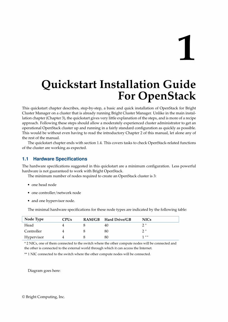
1.1 Hardware SpecificationsThe hardware specifications suggested in this quickstart are a minimum configuration. Less powerfulhardware is not guaranteed to work with Bright OpenStack.
The minimum number of nodes required to create an OpenStack cluster is 3:
• one head node
• one controller/network node
• and one hypervisor node.
The minimal hardware specifications for these node types are indicated by the following table:
Node Type CPUs RAM/GB Hard Drive/GB NICsHead 4 8 40 2 ∗
Controller 4 8 80 2 ∗
Hypervisor 4 8 80 1 ∗∗
* 2 NICs, one of them connected to the switch where the other compute nodes will be connected andthe other is connected to the external world through which it can access the Internet.
** 1 NIC connected to the switch where the other compute nodes will be connected.
Diagram goes here:
© Bright Computing, Inc.
2 Quickstart Installation Guide For OpenStack
1.2 PrerequisitesThe starting point of the quickstart installation for Bright OpenStack requires an up and run-ning Bright Cluster Manager. A quickstart on how to set up Bright Cluster Manager is given inChapter 1 of the Installation Manual (http://support.brightcomputing.com/manuals/7.3/installation-manual.pdf)
The head node must have access to the base distribution repositories and to the Bright repositories.This is because cm-openstack-setup—a utility used in section 1.3—must be able to install packagesfrom these repositories. The head node must therefore be connected to the internet, or it must be able toaccess a local mirror of both repositories.
1.3 Installing Bright OpenStack Using cm-openstack-setup
The cm-openstack-setup script is run from the head node and deploys an OpenStack instance. Anexample session is shown next. This example is based on using node001 as the controller node, andnode002 as the hypervisor node:
[root@bright73 ~]# cm-openstack-setup
Please wait
Connecting to CMDaemon
If all is well, then a deployment screen is seen. The steps are then:
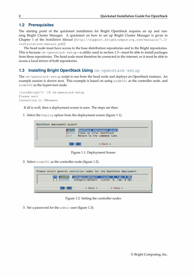
1. Select the Deploy option from the deployment screen (figure 1.1):
Figure 1.1: Deployment Screen
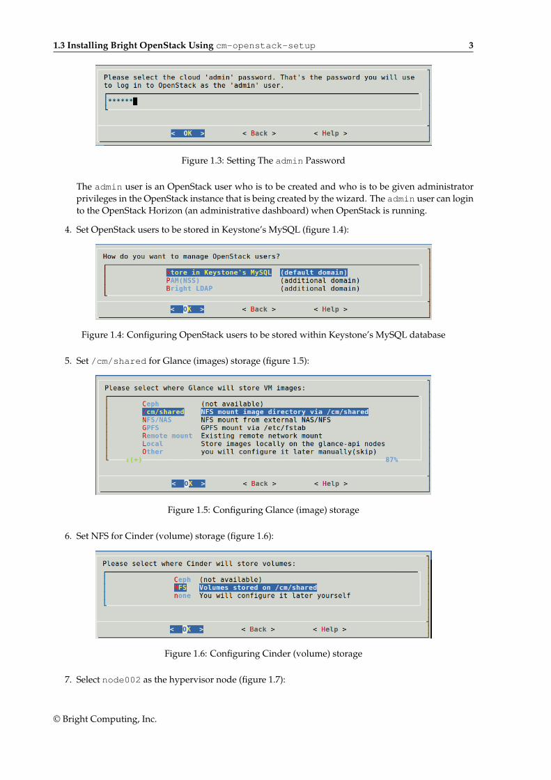
2. Select node001 as the controller node.(figure 1.2):
Figure 1.2: Setting the controller nodes
3. Set a password for the admin user (figure 1.3):
© Bright Computing, Inc.
1.3 Installing Bright OpenStack Using cm-openstack-setup 3
Figure 1.3: Setting The admin Password
The admin user is an OpenStack user who is to be created and who is to be given administratorprivileges in the OpenStack instance that is being created by the wizard. The admin user can loginto the OpenStack Horizon (an administrative dashboard) when OpenStack is running.
4. Set OpenStack users to be stored in Keystone’s MySQL (figure 1.4):
Figure 1.4: Configuring OpenStack users to be stored within Keystone’s MySQL database
5. Set /cm/shared for Glance (images) storage (figure 1.5):
Figure 1.5: Configuring Glance (image) storage
6. Set NFS for Cinder (volume) storage (figure 1.6):
Figure 1.6: Configuring Cinder (volume) storage
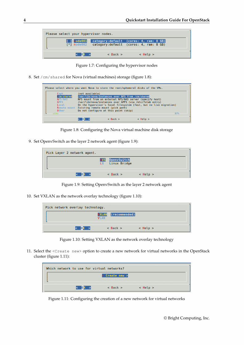
7. Select node002 as the hypervisor node (figure 1.7):
© Bright Computing, Inc.
4 Quickstart Installation Guide For OpenStack
Figure 1.7: Configuring the hypervisor nodes
8. Set /cm/shared for Nova (virtual machines) storage (figure 1.8):
Figure 1.8: Configuring the Nova virtual machine disk storage
9. Set OpenvSwitch as the layer 2 network agent (figure 1.9):
Figure 1.9: Setting OpenvSwitch as the layer 2 network agent
10. Set VXLAN as the network overlay technology (figure 1.10):
Figure 1.10: Setting VXLAN as the network overlay technology
11. Select the <Create new> option to create a new network for virtual networks in the OpenStackcluster (figure 1.11):
Figure 1.11: Configuring the creation of a new network for virtual networks
© Bright Computing, Inc.
1.3 Installing Bright OpenStack Using cm-openstack-setup 5
The default values for the new network can be accepted.
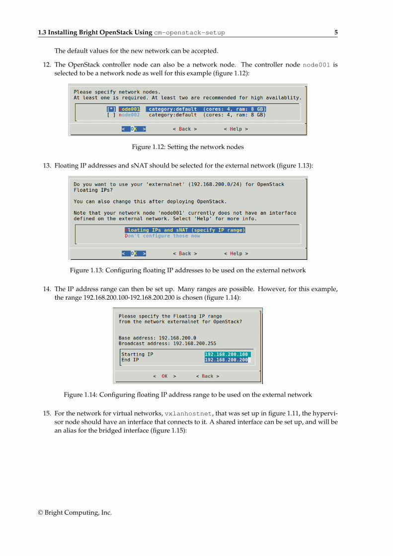
12. The OpenStack controller node can also be a network node. The controller node node001 isselected to be a network node as well for this example (figure 1.12):
Figure 1.12: Setting the network nodes
13. Floating IP addresses and sNAT should be selected for the external network (figure 1.13):
Figure 1.13: Configuring floating IP addresses to be used on the external network
14. The IP address range can then be set up. Many ranges are possible. However, for this example,the range 192.168.200.100-192.168.200.200 is chosen (figure 1.14):
Figure 1.14: Configuring floating IP address range to be used on the external network
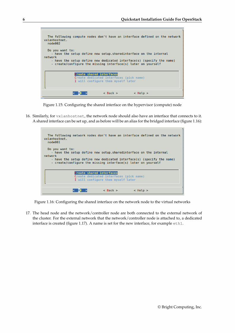
15. For the network for virtual networks, vxlanhostnet, that was set up in figure 1.11, the hypervi-sor node should have an interface that connects to it. A shared interface can be set up, and will bean alias for the bridged interface (figure 1.15):
© Bright Computing, Inc.
6 Quickstart Installation Guide For OpenStack
Figure 1.15: Configuring the shared interface on the hypervisor (compute) node
16. Similarly, for vxlanhostnet, the network node should also have an interface that connects to it.A shared interface can be set up, and as before will be an alias for the bridged interface (figure 1.16):
Figure 1.16: Configuring the shared interface on the network node to the virtual networks
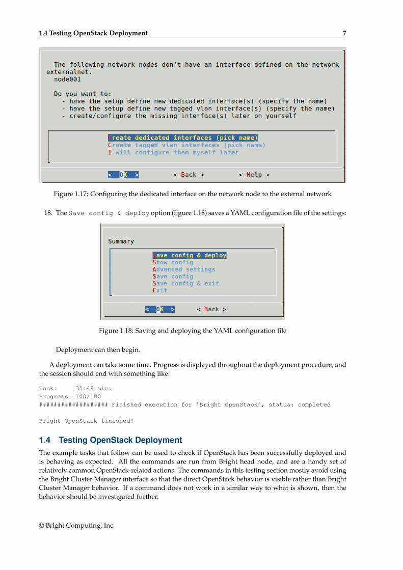
17. The head node and the network/controller node are both connected to the external network ofthe cluster. For the external network that the network/controller node is attached to, a dedicatedinterface is created (figure 1.17). A name is set for the new interface, for example eth1.
© Bright Computing, Inc.
1.4 Testing OpenStack Deployment 7
Figure 1.17: Configuring the dedicated interface on the network node to the external network
18. The Save config & deploy option (figure 1.18) saves a YAML configuration file of the settings:
Figure 1.18: Saving and deploying the YAML configuration file
Deployment can then begin.
A deployment can take some time. Progress is displayed throughout the deployment procedure, andthe session should end with something like:
Took: 35:48 min.
Progress: 100/100
################### Finished execution for ’Bright OpenStack’, status: completed
Bright OpenStack finished!
1.4 Testing OpenStack DeploymentThe example tasks that follow can be used to check if OpenStack has been successfully deployed andis behaving as expected. All the commands are run from Bright head node, and are a handy set ofrelatively common OpenStack-related actions. The commands in this testing section mostly avoid usingthe Bright Cluster Manager interface so that the direct OpenStack behavior is visible rather than BrightCluster Manager behavior. If a command does not work in a similar way to what is shown, then thebehavior should be investigated further.
© Bright Computing, Inc.
8 Quickstart Installation Guide For OpenStack
Download a CirrOS image:
[root@bright73 ~]# wget -P /tmp/images http://download.cirros-cloud.net/0.3.3/cirros-0.3.3-\x86_64-disk.img
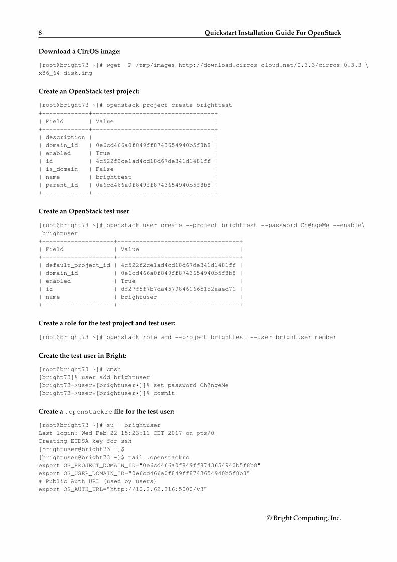
Create an OpenStack test project:
[root@bright73 ~]# openstack project create brighttest
+-------------+----------------------------------+
| Field | Value |
+-------------+----------------------------------+
| description | |
| domain_id | 0e6cd466a0f849ff8743654940b5f8b8 |
| enabled | True |
| id | 4c522f2ce1ad4cd18d67de341d1481ff |
| is_domain | False |
| name | brighttest |
| parent_id | 0e6cd466a0f849ff8743654940b5f8b8 |
+-------------+----------------------------------+
Create an OpenStack test user
[root@bright73 ~]# openstack user create --project brighttest --password Ch@ngeMe --enable\brightuser
+--------------------+----------------------------------+
| Field | Value |
+--------------------+----------------------------------+
| default_project_id | 4c522f2ce1ad4cd18d67de341d1481ff |
| domain_id | 0e6cd466a0f849ff8743654940b5f8b8 |
| enabled | True |
| id | df27f5f7b7da457984616651c2aaed71 |
| name | brightuser |
+--------------------+----------------------------------+
Create a role for the test project and test user:
[root@bright73 ~]# openstack role add --project brighttest --user brightuser member
Create the test user in Bright:
[root@bright73 ~]# cmsh
[bright73]% user add brightuser
[bright73->user*[brightuser*]]% set password Ch@ngeMe
[bright73->user*[brightuser*]]% commit
Create a .openstackrc file for the test user:
[root@bright73 ~]# su - brightuser
Last login: Wed Feb 22 15:23:11 CET 2017 on pts/0
Creating ECDSA key for ssh
[brightuser@bright73 ~]$
[brightuser@bright73 ~]$ tail .openstackrc
export OS_PROJECT_DOMAIN_ID="0e6cd466a0f849ff8743654940b5f8b8"
export OS_USER_DOMAIN_ID="0e6cd466a0f849ff8743654940b5f8b8"
# Public Auth URL (used by users)
export OS_AUTH_URL="http://10.2.62.216:5000/v3"
© Bright Computing, Inc.
1.4 Testing OpenStack Deployment 9
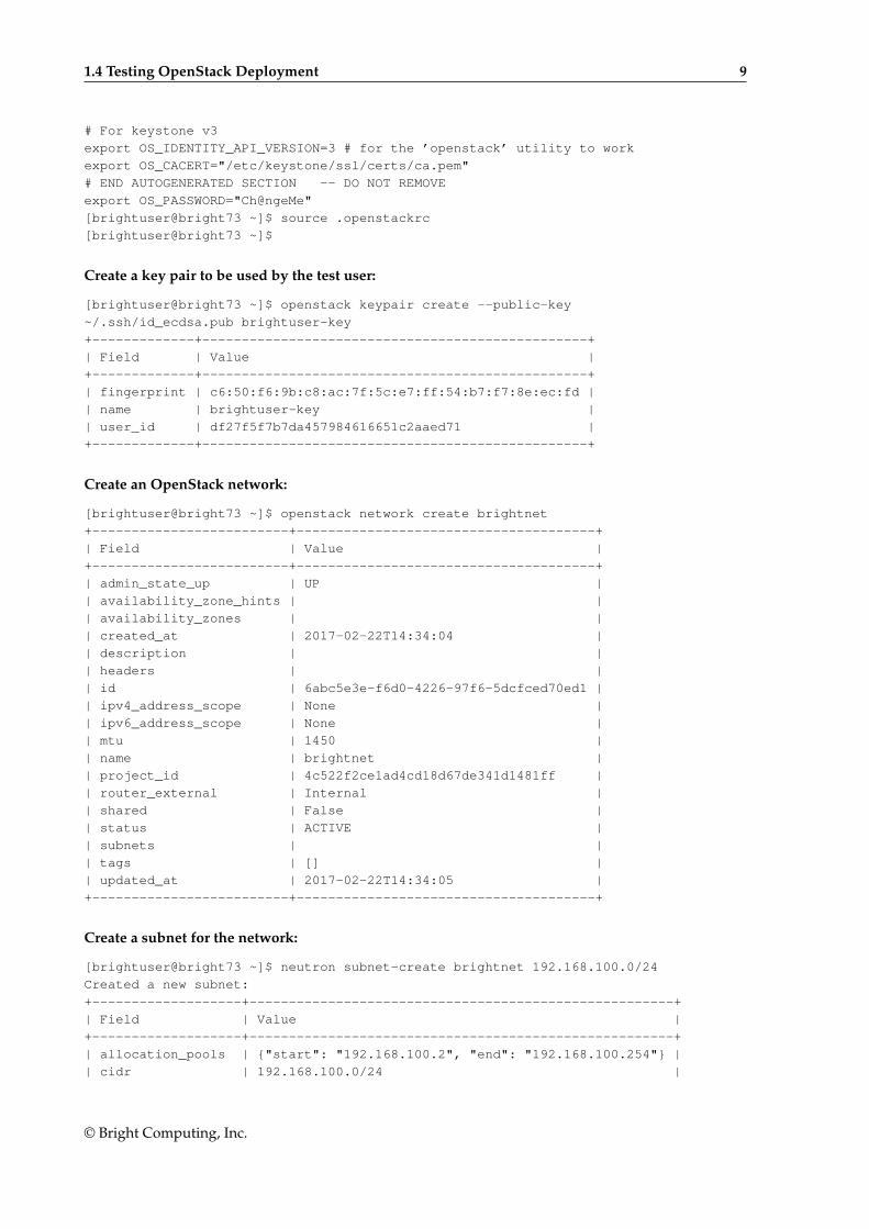
# For keystone v3
export OS_IDENTITY_API_VERSION=3 # for the ’openstack’ utility to work
export OS_CACERT="/etc/keystone/ssl/certs/ca.pem"
# END AUTOGENERATED SECTION -- DO NOT REMOVE
export OS_PASSWORD="Ch@ngeMe"
[brightuser@bright73 ~]$ source .openstackrc
[brightuser@bright73 ~]$
Create a key pair to be used by the test user:
[brightuser@bright73 ~]$ openstack keypair create --public-key
~/.ssh/id_ecdsa.pub brightuser-key
+-------------+-------------------------------------------------+
| Field | Value |
+-------------+-------------------------------------------------+
| fingerprint | c6:50:f6:9b:c8:ac:7f:5c:e7:ff:54:b7:f7:8e:ec:fd |
| name | brightuser-key |
| user_id | df27f5f7b7da457984616651c2aaed71 |
+-------------+-------------------------------------------------+
Create an OpenStack network:
[brightuser@bright73 ~]$ openstack network create brightnet
+-------------------------+--------------------------------------+
| Field | Value |
+-------------------------+--------------------------------------+
| admin_state_up | UP |
| availability_zone_hints | |
| availability_zones | |
| created_at | 2017-02-22T14:34:04 |
| description | |
| headers | |
| id | 6abc5e3e-f6d0-4226-97f6-5dcfced70ed1 |
| ipv4_address_scope | None |
| ipv6_address_scope | None |
| mtu | 1450 |
| name | brightnet |
| project_id | 4c522f2ce1ad4cd18d67de341d1481ff |
| router_external | Internal |
| shared | False |
| status | ACTIVE |
| subnets | |
| tags | [] |
| updated_at | 2017-02-22T14:34:05 |
+-------------------------+--------------------------------------+
Create a subnet for the network:
[brightuser@bright73 ~]$ neutron subnet-create brightnet 192.168.100.0/24
Created a new subnet:
+-------------------+------------------------------------------------------+
| Field | Value |
+-------------------+------------------------------------------------------+
| allocation_pools | {"start": "192.168.100.2", "end": "192.168.100.254"} |
| cidr | 192.168.100.0/24 |
© Bright Computing, Inc.
10 Quickstart Installation Guide For OpenStack
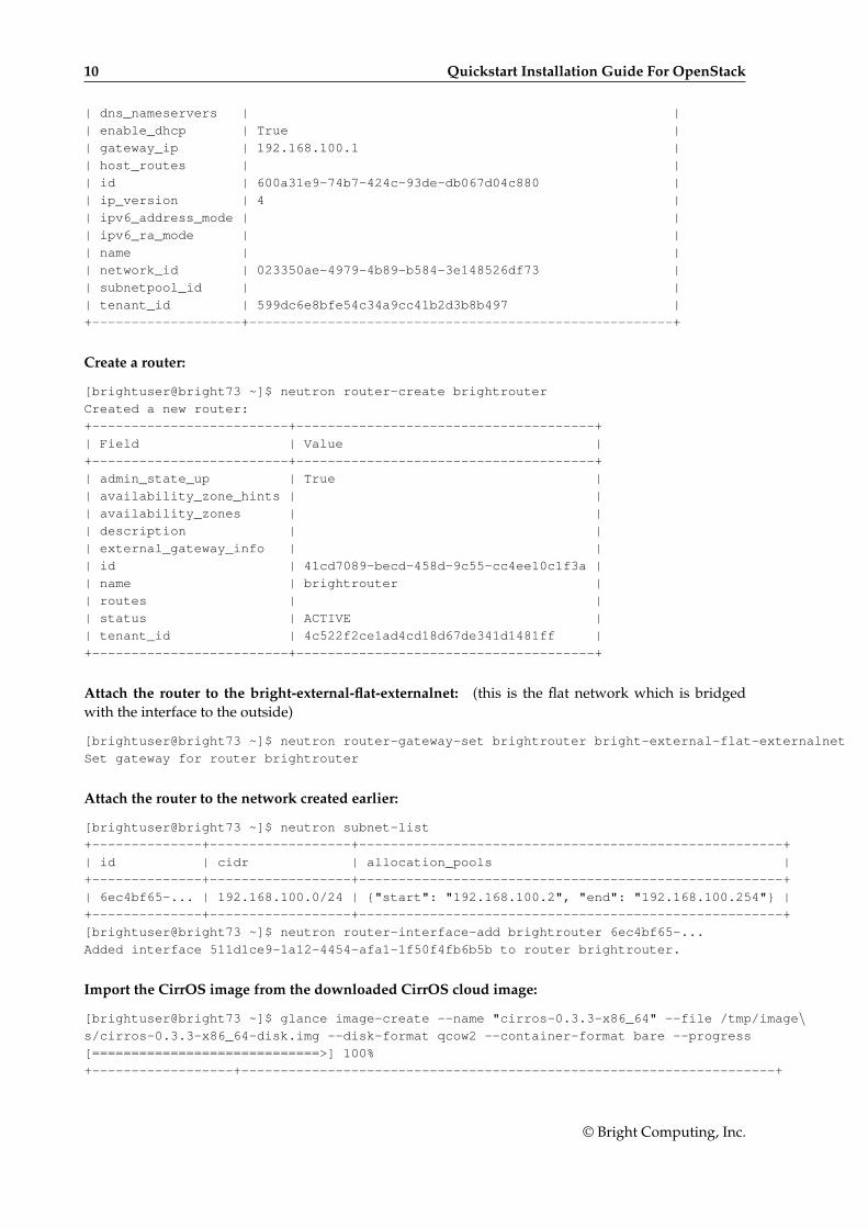
| dns_nameservers | |
| enable_dhcp | True |
| gateway_ip | 192.168.100.1 |
| host_routes | |
| id | 600a31e9-74b7-424c-93de-db067d04c880 |
| ip_version | 4 |
| ipv6_address_mode | |
| ipv6_ra_mode | |
| name | |
| network_id | 023350ae-4979-4b89-b584-3e148526df73 |
| subnetpool_id | |
| tenant_id | 599dc6e8bfe54c34a9cc41b2d3b8b497 |
+-------------------+------------------------------------------------------+
Create a router:
[brightuser@bright73 ~]$ neutron router-create brightrouter
Created a new router:
+-------------------------+--------------------------------------+
| Field | Value |
+-------------------------+--------------------------------------+
| admin_state_up | True |
| availability_zone_hints | |
| availability_zones | |
| description | |
| external_gateway_info | |
| id | 41cd7089-becd-458d-9c55-cc4ee10c1f3a |
| name | brightrouter |
| routes | |
| status | ACTIVE |
| tenant_id | 4c522f2ce1ad4cd18d67de341d1481ff |
+-------------------------+--------------------------------------+
Attach the router to the bright-external-flat-externalnet: (this is the flat network which is bridgedwith the interface to the outside)
[brightuser@bright73 ~]$ neutron router-gateway-set brightrouter bright-external-flat-externalnet
Set gateway for router brightrouter
Attach the router to the network created earlier:
[brightuser@bright73 ~]$ neutron subnet-list
+--------------+------------------+------------------------------------------------------+
| id | cidr | allocation_pools |
+--------------+------------------+------------------------------------------------------+
| 6ec4bf65-... | 192.168.100.0/24 | {"start": "192.168.100.2", "end": "192.168.100.254"} |
+--------------+------------------+------------------------------------------------------+
[brightuser@bright73 ~]$ neutron router-interface-add brightrouter 6ec4bf65-...
Added interface 511d1ce9-1a12-4454-afa1-1f50f4fb6b5b to router brightrouter.
Import the CirrOS image from the downloaded CirrOS cloud image:
[brightuser@bright73 ~]$ glance image-create --name "cirros-0.3.3-x86_64" --file /tmp/image\s/cirros-0.3.3-x86_64-disk.img --disk-format qcow2 --container-format bare --progress
[=============================>] 100%
+------------------+--------------------------------------------------------------------+
© Bright Computing, Inc.
1.4 Testing OpenStack Deployment 11
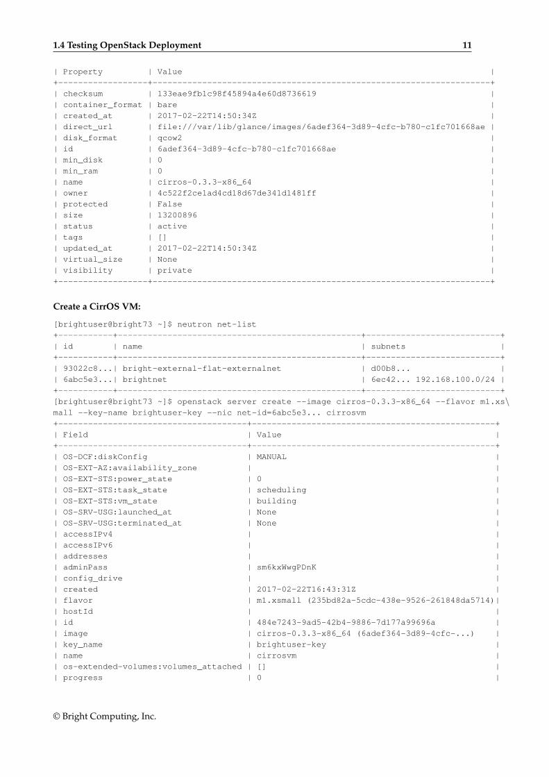
| Property | Value |
+------------------+--------------------------------------------------------------------+
| checksum | 133eae9fb1c98f45894a4e60d8736619 |
| container_format | bare |
| created_at | 2017-02-22T14:50:34Z |
| direct_url | file:///var/lib/glance/images/6adef364-3d89-4cfc-b780-c1fc701668ae |
| disk_format | qcow2 |
| id | 6adef364-3d89-4cfc-b780-c1fc701668ae |
| min_disk | 0 |
| min_ram | 0 |
| name | cirros-0.3.3-x86_64 |
| owner | 4c522f2ce1ad4cd18d67de341d1481ff |
| protected | False |
| size | 13200896 |
| status | active |
| tags | [] |
| updated_at | 2017-02-22T14:50:34Z |
| virtual_size | None |
| visibility | private |
+------------------+--------------------------------------------------------------------+
Create a CirrOS VM:
[brightuser@bright73 ~]$ neutron net-list
+-----------+-------------------------------------------------+---------------------------+
| id | name | subnets |
+-----------+-------------------------------------------------+---------------------------+
| 93022c8...| bright-external-flat-externalnet | d00b8... |
| 6abc5e3...| brightnet | 6ec42... 192.168.100.0/24 |
+-----------+-------------------------------------------------+---------------------------+
[brightuser@bright73 ~]$ openstack server create --image cirros-0.3.3-x86_64 --flavor m1.xs\mall --key-name brightuser-key --nic net-id=6abc5e3... cirrosvm
+--------------------------------------+-------------------------------------------------+
| Field | Value |
+--------------------------------------+-------------------------------------------------+
| OS-DCF:diskConfig | MANUAL |
| OS-EXT-AZ:availability_zone | |
| OS-EXT-STS:power_state | 0 |
| OS-EXT-STS:task_state | scheduling |
| OS-EXT-STS:vm_state | building |
| OS-SRV-USG:launched_at | None |
| OS-SRV-USG:terminated_at | None |
| accessIPv4 | |
| accessIPv6 | |
| addresses | |
| adminPass | sm6kxWwgPDnK |
| config_drive | |
| created | 2017-02-22T16:43:31Z |
| flavor | m1.xsmall (235bd82a-5cdc-438e-9526-261848da5714)|
| hostId | |
| id | 484e7243-9ad5-42b4-9886-7d177a99696a |
| image | cirros-0.3.3-x86_64 (6adef364-3d89-4cfc-...) |
| key_name | brightuser-key |
| name | cirrosvm |
| os-extended-volumes:volumes_attached | [] |
| progress | 0 |
© Bright Computing, Inc.
12 Quickstart Installation Guide For OpenStack
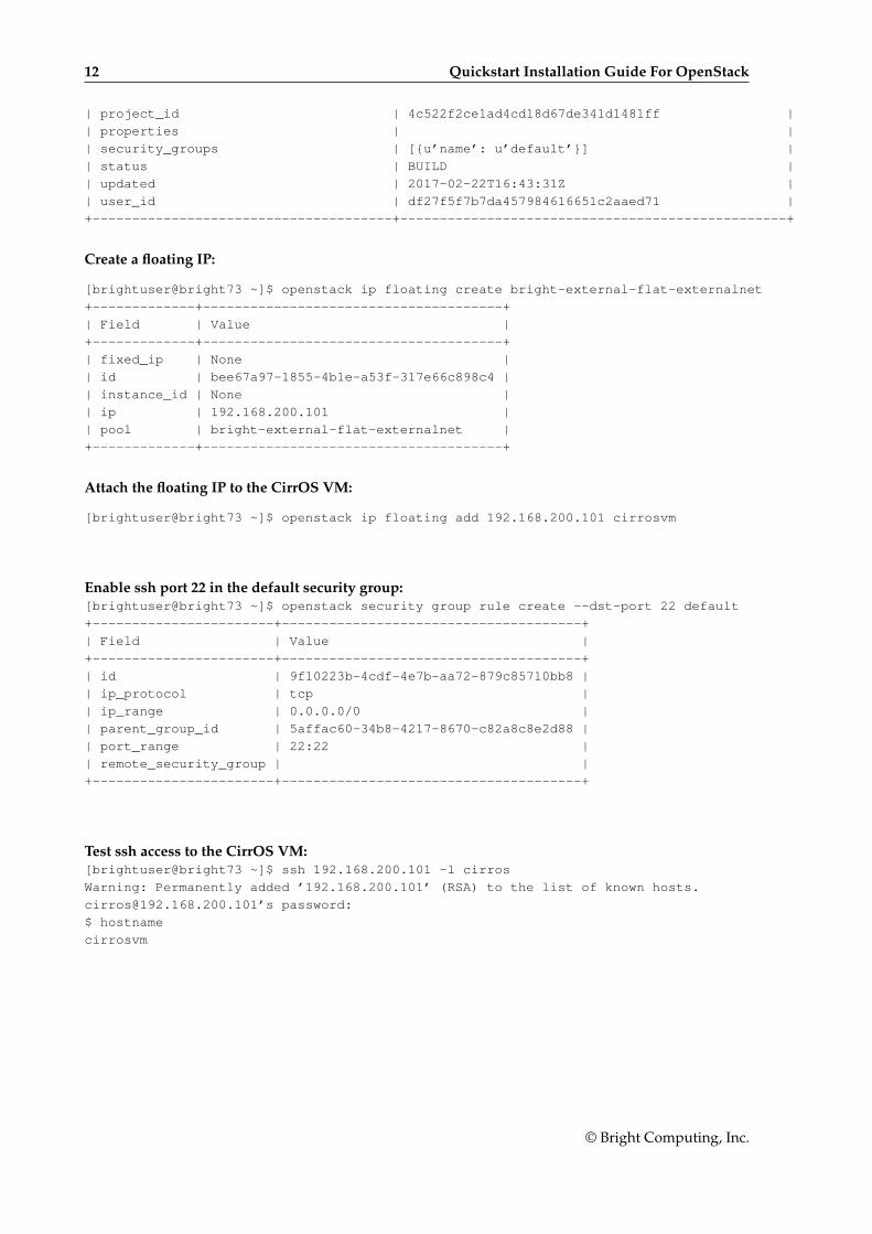
| project_id | 4c522f2ce1ad4cd18d67de341d1481ff |
| properties | |
| security_groups | [{u’name’: u’default’}] |
| status | BUILD |
| updated | 2017-02-22T16:43:31Z |
| user_id | df27f5f7b7da457984616651c2aaed71 |
+--------------------------------------+-------------------------------------------------+
Create a floating IP:
[brightuser@bright73 ~]$ openstack ip floating create bright-external-flat-externalnet
+-------------+--------------------------------------+
| Field | Value |
+-------------+--------------------------------------+
| fixed_ip | None |
| id | bee67a97-1855-4b1e-a53f-317e66c898c4 |
| instance_id | None |
| ip | 192.168.200.101 |
| pool | bright-external-flat-externalnet |
+-------------+--------------------------------------+
Attach the floating IP to the CirrOS VM:
[brightuser@bright73 ~]$ openstack ip floating add 192.168.200.101 cirrosvm
Enable ssh port 22 in the default security group:[brightuser@bright73 ~]$ openstack security group rule create --dst-port 22 default
+-----------------------+--------------------------------------+
| Field | Value |
+-----------------------+--------------------------------------+
| id | 9f10223b-4cdf-4e7b-aa72-879c85710bb8 |
| ip_protocol | tcp |
| ip_range | 0.0.0.0/0 |
| parent_group_id | 5affac60-34b8-4217-8670-c82a8c8e2d88 |
| port_range | 22:22 |
| remote_security_group | |
+-----------------------+--------------------------------------+
Test ssh access to the CirrOS VM:[brightuser@bright73 ~]$ ssh 192.168.200.101 -l cirros
Warning: Permanently added ’192.168.200.101’ (RSA) to the list of known hosts.
[email protected]’s password:
$ hostname
cirrosvm
© Bright Computing, Inc.
2Introduction
OpenStack is an open source implementation of cloud services. It is currently (2017) undergoing rapiddevelopment, and its roadmap is promising.
An implementation of OpenStack, based on the OpenStack Mitaka release (https://www.openstack.org/software/mitaka/) is integrated into the Bright Cluster Manager 7.3 for Open-Stack edition. It is supported for RHEL7 onwards.
The implementation of OpenStack is usable and stable for regular use in common configurations. Ina complex and rapidly-evolving product such as OpenStack, the number of possible unusual configura-tion changes is vast. As a result, the experience of Bright Computing is that Bright Cluster Manager cansometimes run into OpenStack issues while implementing the less common OpenStack configurations.
As one of the supporting organizations of OpenStack, Bright Computing is committed towardsworking together with OpenStack developers to help Bright customers resolve any such issue. Theend result after resolving the issue means that there is a selection pressure that helps evolve that as-pect of OpenStack, so that it becomes convenient and stable for regular use. This process benefits allparticipants in the OpenStack software ecosystem.
OpenStack consists of subsystems, developed as upstream software projects1. A software projectprovides capabilities to OpenStack via the implementation of a backend service, and thereby providesan OpenStack service. The OpenStack service can thus be implemented by interchangeable backends,which projects can provide.
For example, the OpenStack Cinder project provides block storage capabilities to OpenStack via theimplementation of, for example, NFS or Ceph block storage. The OpenStack’s block storage servicecan therefore be implemented by the interchangable backends of the NFS or Ceph projects. Indeed,the entire Cinder project itself can be replaced by a Cinder rewrite from scratch. As far as the user isconcerned the end result is the same.
An analogy to OpenStack is operating system packaging, as provided by distributions:An operating system distribution consists of subsystems, maintained as packages and their depen-
dencies. Some subsystems provide capabilities to the operating system via the implementation of abackend service. The service can often be implemented by interchangeable backends for the subsystem.
A specific example for an operating system distribution would be the mailserver subsystem thatprovides mail delivery capabilities to the operating system via the implementation of, for example,Postfix or Sendmail. The mailserver package and dependencies can therefore be implemented by theinterchangeable backends of the Postfix or Sendmail software. As far as the e-mail user is concerned,the end result is the same.
The project that implements the backend can also change, if the external functionality of the projectremains the same.
Some of the more common OpenStack projects are listed in the following table:
1The term projects must not be confused with the term used in OpenStack elsewhere, where projects, or sometimes tenants,are used to refer to a group of users
© Bright Computing, Inc.

14 Introduction
Service OpenStack Project Managed By Bright
Compute Nova X
Object Storage Swift depends∗
Block Storage Cinder X
Networking Neutron X
Dashboard Horizon X
Identity Service Keystone X
Orchestration Heat X
Telemetry Ceilometer ×Database Service Trove ×Image Service Glance X
* Bright Cluster Manager does not manage the OpenStack referenceimplementation for Swift object storage, but does manage a replace-ment, the API-compatible Ceph RADOS Gateway implementation.
Not all of these projects are integrated, or needed by Bright Cluster Manager for a working Open-Stack system. For example, Bright Cluster Manager already has an extensive monitoring system andtherefore does not for now implement Ceilometer, while Trove is ignored for now until it becomesmore popular.
Projects that are not yet integrated can in principle be added by administrators on top of what isdeployed by Bright Cluster Manager, even though this is not currently supported or tested by BrightComputing. Integration of the more popular of such projects, and greater integration in general, isplanned in future versions of Bright Cluster Manager.
This manual explains the installation, configuration, and some basic use examples of the OpenStackprojects that have so far been integrated with Bright Cluster Manager.
© Bright Computing, Inc.
3OpenStack Installation
To Use Ceph, It Must Be Installed Before Deploying OpenStackIf OpenStack is to access Ceph for storage purposes, for any combination of block storage (Cinder),image storage (Glance), ephemeral storage (Nova), or object storage (RADOS Gateway), then the Cephcomponents must first be installed with cm-ceph-setup (Chapter 4) before starting the OpenStackinstallation procedure covered here.
Hardware Requirement For Running OpenStackThe optimum hardware requirements for OpenStack depend on the intended use. A rule of thumb isthat the number of cores on the compute nodes determines the number of virtual machines.
OpenStack itself can run entirely on one physical machine for limited demonstration purposes.However, if running OpenStack with Bright Cluster Manager, then a standard reference architecture
used by Bright Computing consists of the following three types of nodes:
• A head node.
• Several regular nodes that can be used as hypervisor hosts. Regular nodes (Bright Cluster Managerterminology) are also commonly called compute nodes, and are typically multicore. Runningguest VMs is therefore a suitable use for regular nodes.
• 3 nodes that combine OpenStack controller and OpenStack network node functionality.
For a standard reference configuration, recommended hardware specifications for useful demonstra-tion purposes are:
• Head node: 8GB RAM, 4 cores and two network interfaces. In a standard configuration the headnode does not run OpenStack services, other than the OpenStack-associated Haproxy service.
• Regular nodes: 2GB RAM per core. Each regular node has a network interface.
– In larger clusters, it may be a good idea to separate the OpenStack controller functionalityfrom networking functionality. If a regular node is configured as a controller, then it is best tohave at least 8GB RAM.
• 3 OpenStack controller/network nodes: 8GB RAM and two network interfaces. 3 nodes isthe minimum needed to provide OpenStack high availability via Galera cluster for OpenStackdatabases.
Networking nodes prior to Liberty could run as standalone nodes. In Liberty this is still possible,but not officially supported by OpenStack. Bright Cluster Manager OpenStack edition thereforeuses combined controller/network nodes.
The database for the controller nodes cannot run with two OpenStack controllers. If the admin-istrator would like use something other than the standard reference controller configuration of
© Bright Computing, Inc.
16 OpenStack Installation
3 controllers, then it is possible to run with just one OpenStack controller, without OpenStackdatabase high availability. More than three controllers are also allowed, in a high-availability con-figuration.
The OpenStack controller/network nodes provide:
– OpenStack API endpoint services for Nova, Cinder, Keystone, Neutron, Glance, and Heat.
– Horizon Dashboard. This is a Django-based web service.
– RabbitMQ nodes, deployed as a RabbitMQ cluster. This is used in the OpenStack back-end for internal communication within an OpenStack service. For example, such as be-tween nova-api, nova-conductor, nova-scheduler, nova-compute, or such as be-tween neutron-server and the Neutron L2 agents.
– If Ceph is used, then the controller nodes can also be used as Ceph monitor nodes, in orderto provide high availability for the Ceph monitor node data. In this case, more than 8GB ofmemory is needed for the controller nodes.
An ethernet fabric is used as a terminology to talk about treating the network architecture as beingbased on a giant flat logical OSI Layer 2-style network connected to a single switch, with point-to-point routing, rather than the traditional OSI 2/3 mixture with a hierarchy of access, distribution,and core routers.
The reference architecture networking runs on an ethernet fabric for the:
– internal network of the cluster, which is also the OpenStack management network.
– V(X)LAN network of the cluster, which is used by OpenStack virtual networks.
If Ceph is also deployed, then an ethernet fabric is assumed for:
– The public Ceph network.
– The Ceph replication network.
– An optional external network that is used to access virtual machines in OpenStack via Float-ing IPs.
Hard drive requirements for minimal systems can remain as for those required for a regular BrightCluster Manager cluster. For production systems, these minimal requirements are however unlikely towork for very long. Storage requirements should therefore be considered with care according to the usecase. If necessary, Bright Computing can provide advice on this.
Running OpenStack under Bright Cluster Manager with fewer resources than suggested in the pre-ceding is possible but may cause issues. While such issues can be resolved, they are usually not worththe time spent analyzing them, due to the great number of possible configurations. It is better to runwith ample resources, and then analyze the resource consumption in the configuration that is used, tosee what issues to be aware of when scaling up to a production system.
Running a Bright Cluster Manager OpenStack cluster that varies greatly from the reference cluster isalso possible. If necessary, Bright Computing can provide advice on this.
Ways Of Installing OpenStackThe version of OpenStack that is integrated with Bright Cluster Manager can be installed in the follow-ing two ways:
• Using the GUI-based Setup Wizard button from within cmgui (section 3.1). This is the recom-mended installation method.
• Using the text-based cm-openstack-setup utility (section 3.2). The utility is a part of the stan-dard cluster-tools package.
© Bright Computing, Inc.
3.1 Installation Of OpenStack From cmgui 17
The priorities that the package manager uses are expected to be at their default settings, in order forthe installation to work.
By default, deploying OpenStack installs the following projects: Keystone, Nova, Cinder, Glance,Neutron, Heat and Horizon (the dashboard).
If Ceph is used, then Bright also can also optionally deploy RADOS Gateway to be used as a Swift-API-compatible object storage system. Using RADOS Gateway instead of the reference Swift objectstorage is regarded in the OpenStack community as good practice, and is indeed the only object storagesystem that Bright Cluster Manager manages for OpenStack. Alternative backend storage is possible atthe same time as object storage, which means, for example, that block and image storage are optionsthat can be used in a cluster at the same time as object storage.
3.1 Installation Of OpenStack From cmgui
The cmgui OpenStack Setup Wizard is the preferred way to install OpenStack. A prerequisite forrunning it is that the head node should be able to connect to the distribution repositories, or alternativelythe head node should have OpenStack RPMs preinstalled on it. Preinstalled OpenStack RPMs can beconfigured as part of the head node installation from the ISO, if the ISO that is used the Bright ClusterManager OpenStack edition.
Some suggestions and background notes These are given here to help the administrator understandwhat the setup configuration does, and to help simplify deployment. Looking at these notes after adry-run with the wizard will probably be helpful.
• A VXLAN (Virtual Extensible LAN) network is similar to a VLAN network in function, but hasfeatures that make it more suited to cloud computing.
– If VXLANs are to be used, then the wizard is able to help create a VXLAN overlay network forOpenStack tenant networks.An OpenStack tenant network is a network used by a group of users allocated to a particularvirtual cluster.A VXLAN overlay network is a Layer 2 network “overlaid” on top of a Layer 3 network.The VXLAN overlay network is a virtual LAN that runs its frames encapsulated within UDPpackets over the regular TCP/IP network infrastructure. It is very similar to VLAN technol-ogy, but with some design features that make it more useful for cloud computing needs. Onemajor improvement is that around 16 million VXLANs can be made to run over the under-lying Layer 3 network. This is in contrast to the 4,000 or so VLANs that can be made to runover their underlying Layer 2 network, if the switch port supports that level of simultaneouscapability.By default, if the VXLAN network and VXLAN network object do not exist, then the wizardhelps the administrator create a vxlanhostnet network and network object (section 3.1.11).The network is attached to, and the object is associated with, all non-head nodes taking part inthe OpenStack deployment. If a vxlanhostnet network is pre-created beforehand, then thewizard can guide the administrator to associate a network object with it, and ensure that allthe non-head nodes participating in the OpenStack deployment are attached and associatedaccordingly.
– The VXLAN network runs over an IP network. It should therefore have its own IP range,and each node on that network should have an IP address. By default, a network range of10.161.0.0/16 is suggested in the VXLAN configuration screen (section 3.1.11, figure 3.12).
– The VXLAN network can run over a dedicated physical network, but it can also run overan alias interface on top of an existing internal network interface. The choice is up to theadministrator.
© Bright Computing, Inc.
18 OpenStack Installation
– It is possible to deploy OpenStack without VXLAN overlay networks if user instances aregiven access to the internal network. Care must then be taken to avoid IP addressing conflicts.
• When allowing for Floating IPs and/or enabling outbound connectivity from the virtual machines(VMs) to the external network via the network node, the network node can be pre-configuredmanually according to how it is connected to the internal and external networks. Otherwise, ifthe node is not pre-configured manually, the wizard then carries out a basic configuration on thenetwork node that
– configures one physical interface of the network node to be connected to the internal network,so that the network node can route packets for nodes on the internal network.
– configures the other physical interface of the network node to be connected to the externalnetwork so that the network node can route packets from external nodes.
The wizard asks the user several questions on the details of how OpenStack is to be deployed. Fromthe answers, it generates an YAML document with the intended configuration. Then, in the back-end,largely hidden from the user, it runs the text-based cm-openstack-setup script (section 3.2) with thisconfiguration on the active head node. In other words, the wizard can be regarded as a GUI front endto the cm-openstack-setup utility.
The practicalities of executing the wizard: The explanations given by the wizard during its executionsteps are intended to be verbose enough so that the administrator can follow what is happening.
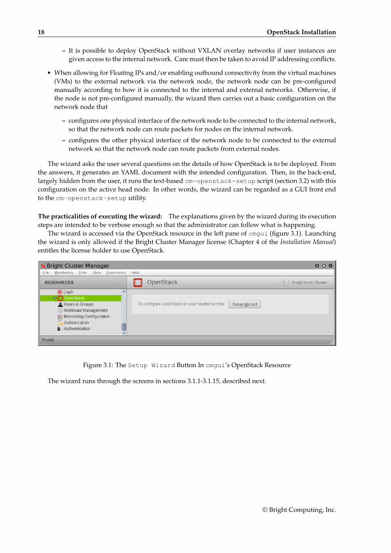
The wizard is accessed via the OpenStack resource in the left pane of cmgui (figure 3.1). Launchingthe wizard is only allowed if the Bright Cluster Manager license (Chapter 4 of the Installation Manual)entitles the license holder to use OpenStack.
Figure 3.1: The Setup Wizard Button In cmgui’s OpenStack Resource
The wizard runs through the screens in sections 3.1.1-3.1.15, described next.
© Bright Computing, Inc.
3.1 Installation Of OpenStack From cmgui 19
3.1.1 OpenStack Setup Wizard Overview
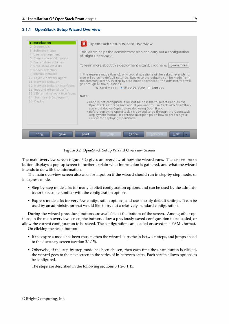
Figure 3.2: OpenStack Setup Wizard Overview Screen
The main overview screen (figure 3.2) gives an overview of how the wizard runs. The Learn morebutton displays a pop up screen to further explain what information is gathered, and what the wizardintends to do with the information.
The main overview screen also asks for input on if the wizard should run in step-by-step mode, orin express mode.
• Step-by-step mode asks for many explicit configuration options, and can be used by the adminis-trator to become familiar with the configuration options.
• Express mode asks for very few configuration options, and uses mostly default settings. It can beused by an administrator that would like to try out a relatively standard configuration.
During the wizard procedure, buttons are available at the bottom of the screen. Among other op-tions, in the main overview screen, the buttons allow a previously-saved configuration to be loaded, orallow the current configuration to be saved. The configurations are loaded or saved in a YAML format.
On clicking the Next button:
• If the express mode has been chosen, then the wizard skips the in-between steps, and jumps aheadto the Summary screen (section 3.1.15).
• Otherwise, if the step-by-step mode has been chosen, then each time the Next button is clicked,the wizard goes to the next screen in the series of in-between steps. Each screen allows options tobe configured.
The steps are described in the following sections 3.1.2-3.1.15.
© Bright Computing, Inc.
20 OpenStack Installation
3.1.2 OpenStack admin User Screen
Figure 3.3: OpenStack admin User Screen
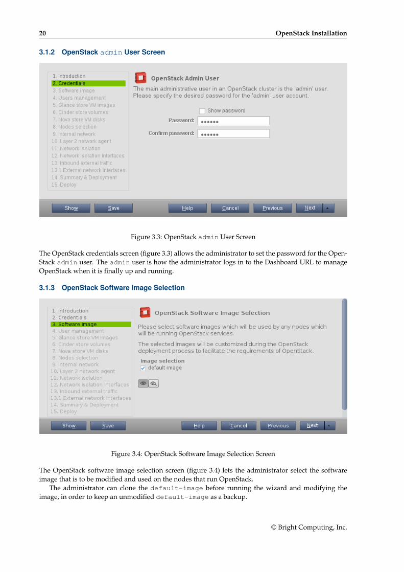
The OpenStack credentials screen (figure 3.3) allows the administrator to set the password for the Open-Stack admin user. The admin user is how the administrator logs in to the Dashboard URL to manageOpenStack when it is finally up and running.
3.1.3 OpenStack Software Image Selection
Figure 3.4: OpenStack Software Image Selection Screen
The OpenStack software image selection screen (figure 3.4) lets the administrator select the softwareimage that is to be modified and used on the nodes that run OpenStack.
The administrator can clone the default-image before running the wizard and modifying theimage, in order to keep an unmodified default-image as a backup.
© Bright Computing, Inc.
3.1 Installation Of OpenStack From cmgui 21
The administrator should take care not to move a node with OpenStack roles to another categorythat contains a different image without OpenStack roles. OpenStack nodes behave quite differentlyfrom non-OpenStack nodes.
3.1.4 User Management
Figure 3.5: OpenStack User Management Screen
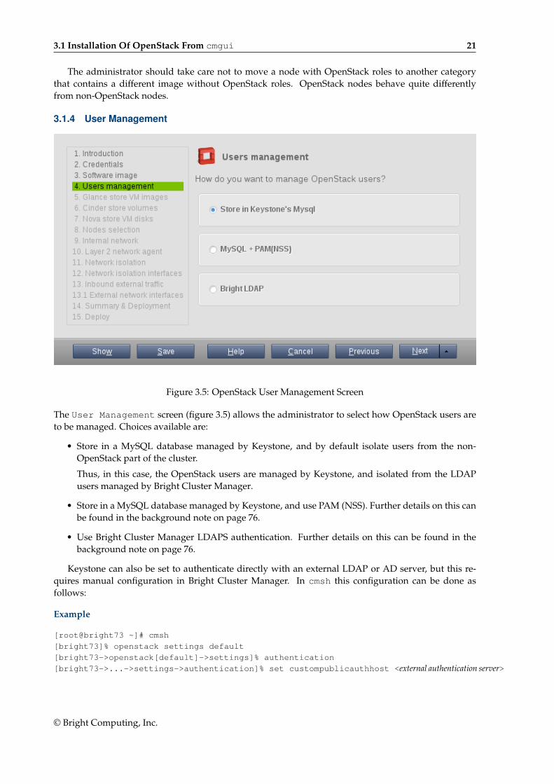
The User Management screen (figure 3.5) allows the administrator to select how OpenStack users areto be managed. Choices available are:
• Store in a MySQL database managed by Keystone, and by default isolate users from the non-OpenStack part of the cluster.
Thus, in this case, the OpenStack users are managed by Keystone, and isolated from the LDAPusers managed by Bright Cluster Manager.
• Store in a MySQL database managed by Keystone, and use PAM (NSS). Further details on this canbe found in the background note on page 76.
• Use Bright Cluster Manager LDAPS authentication. Further details on this can be found in thebackground note on page 76.
Keystone can also be set to authenticate directly with an external LDAP or AD server, but this re-quires manual configuration in Bright Cluster Manager. In cmsh this configuration can be done asfollows:
Example
[root@bright73 ~]# cmsh
[bright73]% openstack settings default
[bright73->openstack[default]->settings]% authentication
[bright73->...->settings->authentication]% set custompublicauthhost <external authentication server>
© Bright Computing, Inc.
22 OpenStack Installation
3.1.5 Glance VM Image Storage
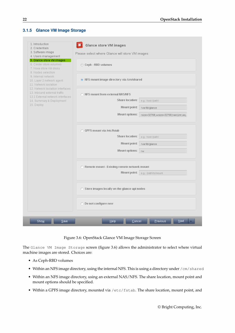
Figure 3.6: OpenStack Glance VM Image Storage Screen
The Glance VM Image Storage screen (figure 3.6) allows the administrator to select where virtualmachine images are stored. Choices are:
• As Ceph-RBD volumes
• Within an NFS image directory, using the internal NFS. This is using a directory under /cm/shared
• Within an NFS image directory, using an external NAS/NFS. The share location, mount point andmount options should be specified.
• Within a GPFS image directory, mounted via /etc/fstab. The share location, mount point, and
© Bright Computing, Inc.
3.1 Installation Of OpenStack From cmgui 23
mount options should be specified.
• Using a remote mount from another network file system. The mount point should be specified.
• As images stored locally on the glance-api nodes.
3.1.6 Cinder Volume Storage
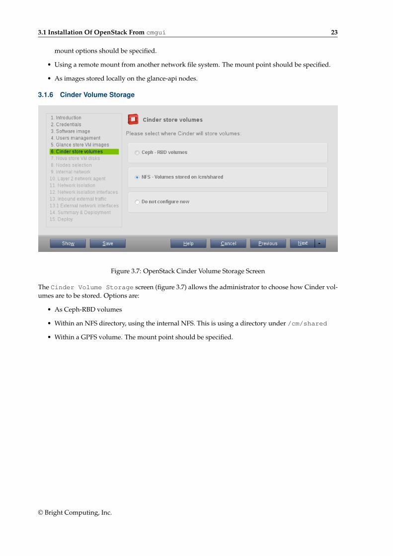
Figure 3.7: OpenStack Cinder Volume Storage Screen
The Cinder Volume Storage screen (figure 3.7) allows the administrator to choose how Cinder vol-umes are to be stored. Options are:
• As Ceph-RBD volumes
• Within an NFS directory, using the internal NFS. This is using a directory under /cm/shared
• Within a GPFS volume. The mount point should be specified.
© Bright Computing, Inc.
24 OpenStack Installation
3.1.7 Nova VM Disks Storage
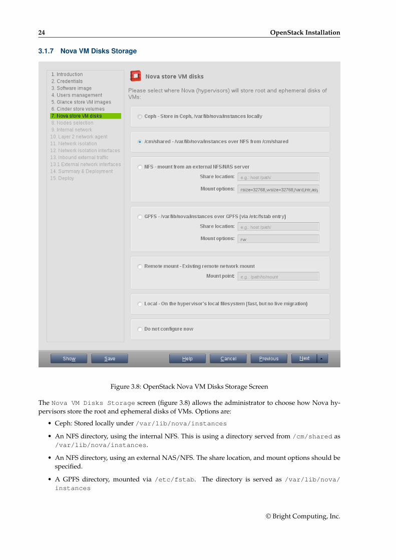
Figure 3.8: OpenStack Nova VM Disks Storage Screen
The Nova VM Disks Storage screen (figure 3.8) allows the administrator to choose how Nova hy-pervisors store the root and ephemeral disks of VMs. Options are:
• Ceph: Stored locally under /var/lib/nova/instances
• An NFS directory, using the internal NFS. This is using a directory served from /cm/shared as/var/lib/nova/instances.
• An NFS directory, using an external NAS/NFS. The share location, and mount options should bespecified.
• A GPFS directory, mounted via /etc/fstab. The directory is served as /var/lib/nova/instances
© Bright Computing, Inc.
3.1 Installation Of OpenStack From cmgui 25
• A remote mount from another network file system. The mount point should be specified.
• A local filesystem on the hypervisor itself, under /var/lib/nova. This is fast, but does notsupport live migration.
3.1.8 OpenStack Nodes Selection
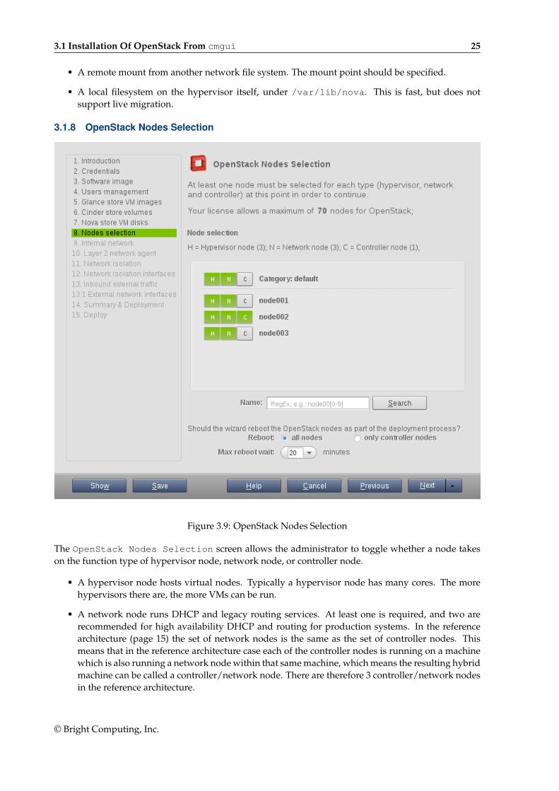
Figure 3.9: OpenStack Nodes Selection
The OpenStack Nodes Selection screen allows the administrator to toggle whether a node takeson the function type of hypervisor node, network node, or controller node.
• A hypervisor node hosts virtual nodes. Typically a hypervisor node has many cores. The morehypervisors there are, the more VMs can be run.
• A network node runs DHCP and legacy routing services. At least one is required, and two arerecommended for high availability DHCP and routing for production systems. In the referencearchitecture (page 15) the set of network nodes is the same as the set of controller nodes. Thismeans that in the reference architecture case each of the controller nodes is running on a machinewhich is also running a network node within that same machine, which means the resulting hybridmachine can be called a controller/network node. There are therefore 3 controller/network nodesin the reference architecture.
© Bright Computing, Inc.
26 OpenStack Installation
• A controller node runs RabbitMQ services. At least one is required, and three are recommendedfor high-availability production systems.
Each of these three function types must exist at least once in the cluster. Each node can have multiplefunctions types, and each function type can be allocated to many nodes. Combining hypervisor nodeswith controller nodes is however usually not recommended, due to the high CPU load from controllerservices.
An often convenient way to set the function types is by category first, and individually next. Forexample nodes that are to be hypervisors and controllers can have their function type set at categorylevel, by clicking on the category toggles. An individual node in a category can then have a missingfunction type added to it as a variation on the category-level configuration in this screen.
For example, in figure 3.9, the category level has the hypervisor node and network node functiontypes set. This means that node001, node002, and node003 all inherit these function types in their con-figuration. In addition, node002 has individually had the controller function type added to it.
Within the OpenStack Nodes Selection screen, the full list of nodes can be searched throughwith a regex search. This highlights the searched-for list of nodes.
When the OpenStack installation wizard completes, and configuration is deployed, the OpenStacknodes are all set to reboot by default. However, the OpenStack Nodes Selection screen also allowsthe rebooting of just the controller nodes, which is often sufficient.
When a node reboots, it can take some time to be provisioned. The time to wait for reboot is config-urable in the OpenStack Nodes Selection screen.
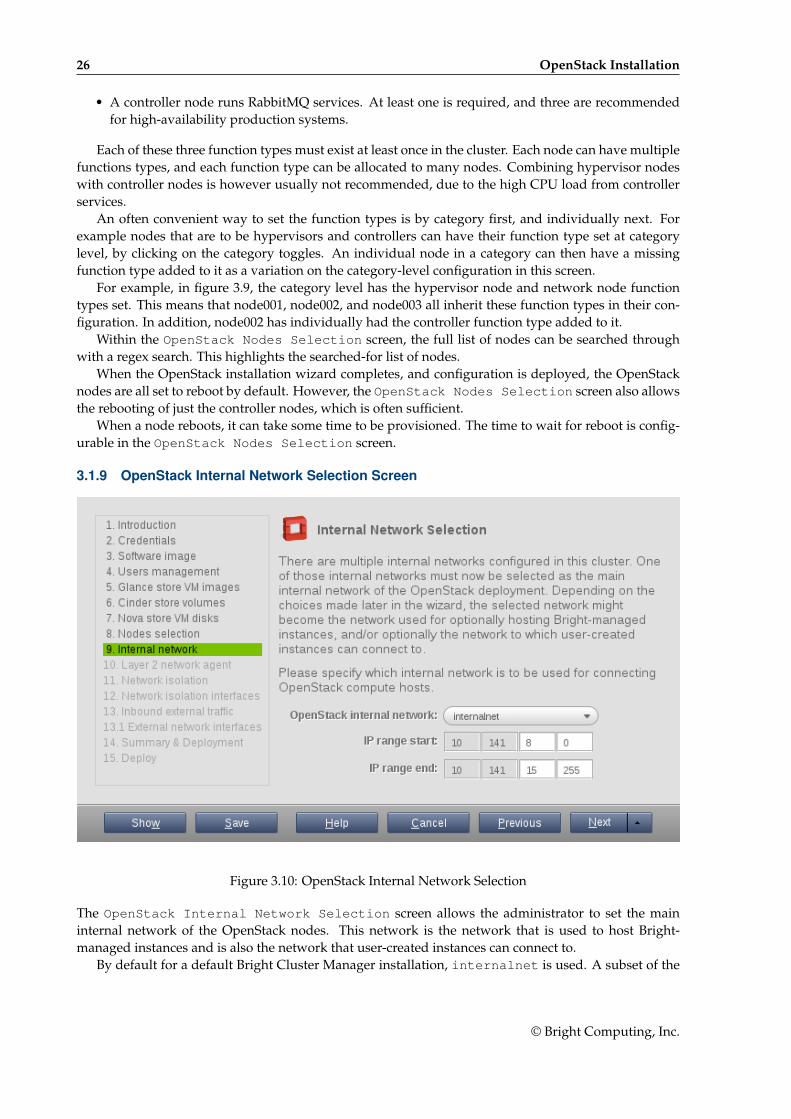
3.1.9 OpenStack Internal Network Selection Screen
Figure 3.10: OpenStack Internal Network Selection
The OpenStack Internal Network Selection screen allows the administrator to set the maininternal network of the OpenStack nodes. This network is the network that is used to host Bright-managed instances and is also the network that user-created instances can connect to.
By default for a default Bright Cluster Manager installation, internalnet is used. A subset of the
© Bright Computing, Inc.
3.1 Installation Of OpenStack From cmgui 27
network is configured for OpenStack use by setting appropriate IP ranges.
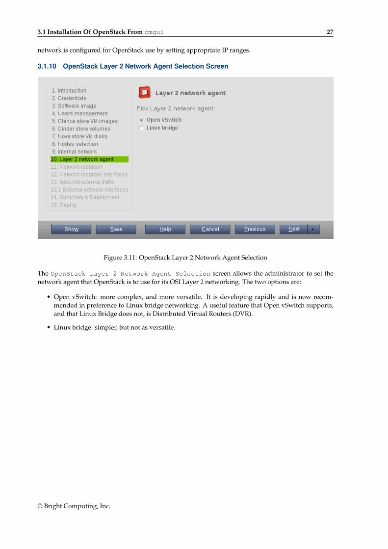
3.1.10 OpenStack Layer 2 Network Agent Selection Screen
Figure 3.11: OpenStack Layer 2 Network Agent Selection
The OpenStack Layer 2 Network Agent Selection screen allows the administrator to set thenetwork agent that OpenStack is to use for its OSI Layer 2 networking. The two options are:
• Open vSwitch: more complex, and more versatile. It is developing rapidly and is now recom-mended in preference to Linux bridge networking. A useful feature that Open vSwitch supports,and that Linux Bridge does not, is Distributed Virtual Routers (DVR).
• Linux bridge: simpler, but not as versatile.
© Bright Computing, Inc.
28 OpenStack Installation
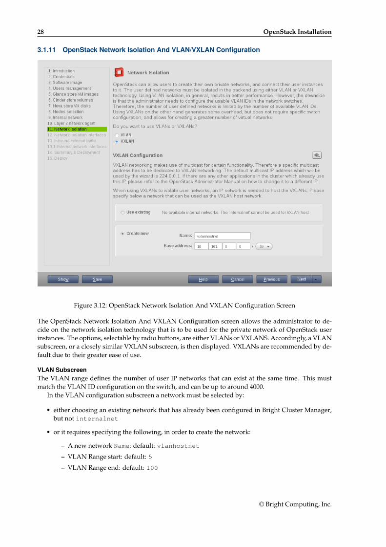
3.1.11 OpenStack Network Isolation And VLAN/VXLAN Configuration
Figure 3.12: OpenStack Network Isolation And VXLAN Configuration Screen
The OpenStack Network Isolation And VXLAN Configuration screen allows the administrator to de-cide on the network isolation technology that is to be used for the private network of OpenStack userinstances. The options, selectable by radio buttons, are either VLANs or VXLANS. Accordingly, a VLANsubscreen, or a closely similar VXLAN subscreen, is then displayed. VXLANs are recommended by de-fault due to their greater ease of use.
VLAN SubscreenThe VLAN range defines the number of user IP networks that can exist at the same time. This mustmatch the VLAN ID configuration on the switch, and can be up to around 4000.
In the VLAN configuration subscreen a network must be selected by:
• either choosing an existing network that has already been configured in Bright Cluster Manager,but not internalnet
• or it requires specifying the following, in order to create the network:
– A new network Name: default: vlanhostnet
– VLAN Range start: default: 5
– VLAN Range end: default: 100
© Bright Computing, Inc.
3.1 Installation Of OpenStack From cmgui 29
VXLAN SubscreenThe VXLAN range defines the number of user IP networks that can exist at the same time. While therange can be set to be around 16 million, it is best to keep it to a more reasonable size, such as 50,000,since a larger range slows down Neutron significantly.
An IP network is needed to host the VXLANs and allow the tunneling of traffic between VXLANendpoints. This requires
• either choosing an existing network that has already been configured in Bright Cluster Manager,but not internalnet
• or it requires specifying the following, in order to create the network:
– A new network Name: default: vxlanhostnet
– Base address: default: 10.161.0.0
– Netmask bits: default: 16
In the VXLAN configuration subscreen, if the icon to view details is clicked, then the following extraoptions are suggested, with overrideable defaults as listed:
• VXLAN Range start: default: 1
• VXLAN Range end: default: 50000
VXLAN networking uses a multicast address to handle broadcast traffic in a virtual network.The default multicast IP address that is set, 224.0.0.1, is unlikely to be used by another appli-cation. However, if there is a conflict, then the address can be changed using the CMDaemonOpenStackVXLANGroup directive (Appendix C, page 600 of the Administrator Manual).
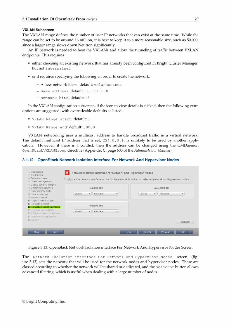
3.1.12 OpenStack Network Isolation interface For Network And Hypervisor Nodes
Figure 3.13: OpenStack Network Isolation interface For Network And Hypervisor Nodes Screen
The Network Isolation interface For Network And Hypervisor Nodes screen (fig-ure 3.13) sets the network that will be used for the network nodes and hypervisor nodes. These areclassed according to whether the network will be shared or dedicated, and the Selector button allowsadvanced filtering, which is useful when dealing with a large number of nodes.
© Bright Computing, Inc.
30 OpenStack Installation
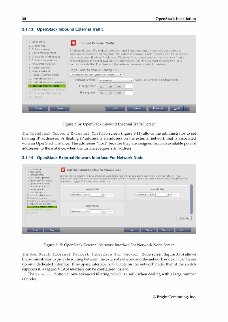
3.1.13 OpenStack Inbound External Traffic
Figure 3.14: OpenStack Inbound External Traffic Screen
The OpenStack Inbound External Traffic screen (figure 3.14) allows the administrator to setfloating IP addresses. A floating IP address is an address on the external network that is associatedwith an OpenStack instance. The addresses “float” because they are assigned from an available pool ofaddresses, to the instance, when the instance requests an address.
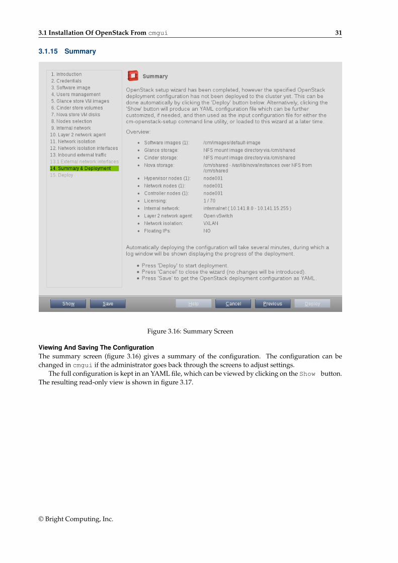
3.1.14 OpenStack External Network Interface For Network Node
Figure 3.15: OpenStack External Network Interface For Network Node Screen
The OpenStack External Network Interface For Network Node screen (figure 3.15) allowsthe administrator to provide routing between the external network and the network nodes. It can be setup on a dedicated interface. If no spare interface is available on the network node, then if the switchsupports it, a tagged VLAN interface can be configured instead.
The Selector button allows advanced filtering, which is useful when dealing with a large numberof nodes.
© Bright Computing, Inc.
3.1 Installation Of OpenStack From cmgui 31
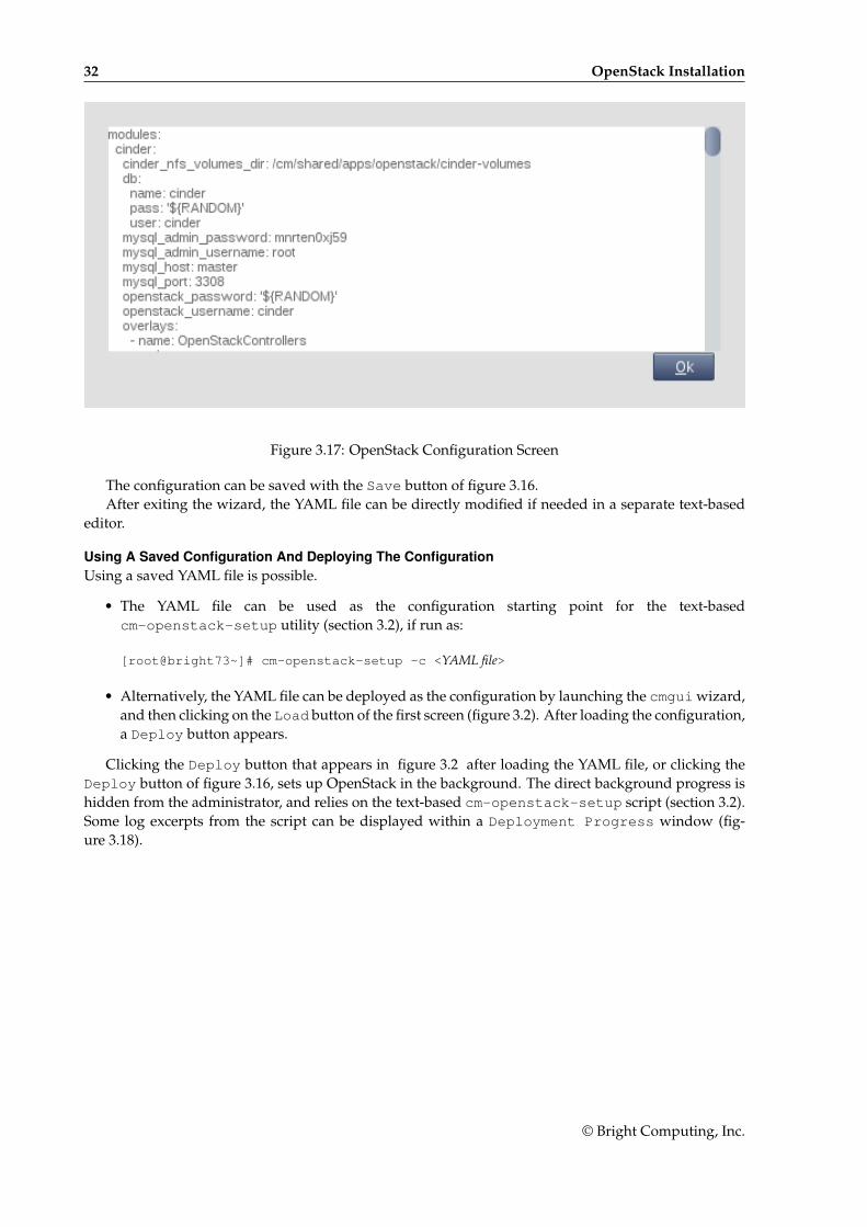
3.1.15 Summary
Figure 3.16: Summary Screen
Viewing And Saving The ConfigurationThe summary screen (figure 3.16) gives a summary of the configuration. The configuration can bechanged in cmgui if the administrator goes back through the screens to adjust settings.
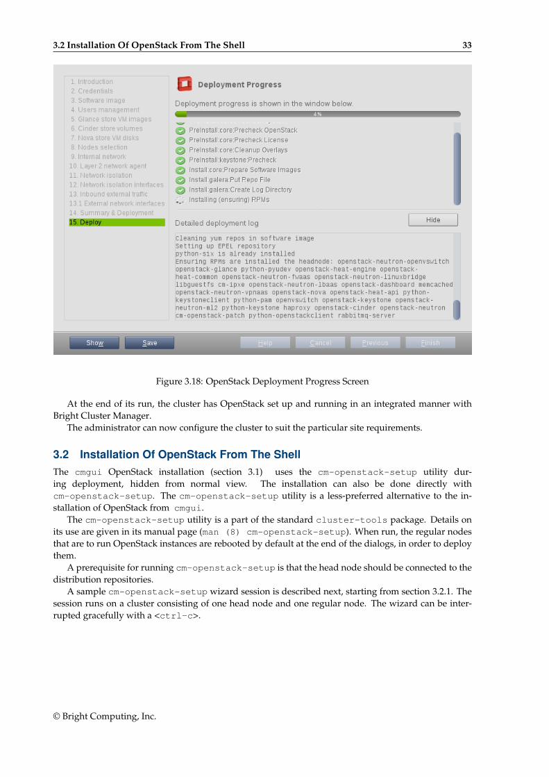
The full configuration is kept in an YAML file, which can be viewed by clicking on the Show button.The resulting read-only view is shown in figure 3.17.
© Bright Computing, Inc.
32 OpenStack Installation
Figure 3.17: OpenStack Configuration Screen
The configuration can be saved with the Save button of figure 3.16.After exiting the wizard, the YAML file can be directly modified if needed in a separate text-based
editor.
Using A Saved Configuration And Deploying The ConfigurationUsing a saved YAML file is possible.
• The YAML file can be used as the configuration starting point for the text-basedcm-openstack-setup utility (section 3.2), if run as:
[root@bright73~]# cm-openstack-setup -c <YAML file>
• Alternatively, the YAML file can be deployed as the configuration by launching the cmgui wizard,and then clicking on the Load button of the first screen (figure 3.2). After loading the configuration,a Deploy button appears.
Clicking the Deploy button that appears in figure 3.2 after loading the YAML file, or clicking theDeploy button of figure 3.16, sets up OpenStack in the background. The direct background progress ishidden from the administrator, and relies on the text-based cm-openstack-setup script (section 3.2).Some log excerpts from the script can be displayed within a Deployment Progress window (fig-ure 3.18).
© Bright Computing, Inc.
3.2 Installation Of OpenStack From The Shell 33
Figure 3.18: OpenStack Deployment Progress Screen
At the end of its run, the cluster has OpenStack set up and running in an integrated manner withBright Cluster Manager.
The administrator can now configure the cluster to suit the particular site requirements.
3.2 Installation Of OpenStack From The ShellThe cmgui OpenStack installation (section 3.1) uses the cm-openstack-setup utility dur-ing deployment, hidden from normal view. The installation can also be done directly withcm-openstack-setup. The cm-openstack-setup utility is a less-preferred alternative to the in-stallation of OpenStack from cmgui.
The cm-openstack-setup utility is a part of the standard cluster-tools package. Details onits use are given in its manual page (man (8) cm-openstack-setup). When run, the regular nodesthat are to run OpenStack instances are rebooted by default at the end of the dialogs, in order to deploythem.
A prerequisite for running cm-openstack-setup is that the head node should be connected to thedistribution repositories.
A sample cm-openstack-setup wizard session is described next, starting from section 3.2.1. Thesession runs on a cluster consisting of one head node and one regular node. The wizard can be inter-rupted gracefully with a <ctrl-c>.
© Bright Computing, Inc.
34 OpenStack Installation
3.2.1 Start Screen
Figure 3.19: Start Screen
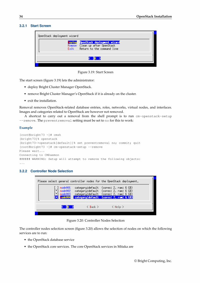
The start screen (figure 3.19) lets the administrator:
• deploy Bright Cluster Manager OpenStack.
• remove Bright Cluster Manager’s OpenStack if it is already on the cluster.
• exit the installation.
Removal removes OpenStack-related database entries, roles, networks, virtual nodes, and interfaces.Images and categories related to OpenStack are however not removed.
A shortcut to carry out a removal from the shell prompt is to run cm-openstack-setup--remove. The preventremoval setting must be set to no for this to work:
Example
[root@bright73 ~]# cmsh
[bright73]% openstack
[bright73->openstack[default]]% set preventremoval no; commit; quit
[root@bright73 ~]# cm-openstack-setup --remove
Please wait...
Connecting to CMDaemon
###### WARNING: Setup will attempt to remove the following objects:
...
3.2.2 Controller Node Selection
Figure 3.20: Controller Nodes Selection
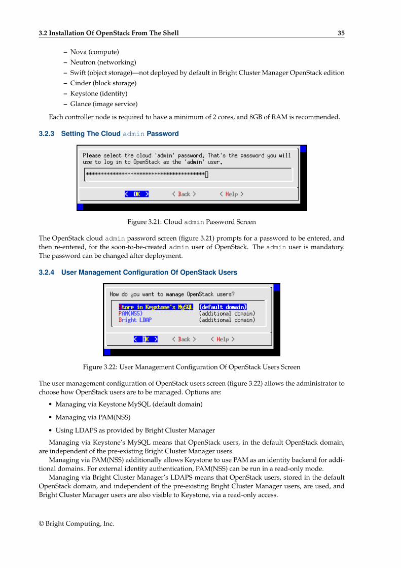
The controller nodes selection screen (figure 3.20) allows the selection of nodes on which the followingservices are to run:
• the OpenStack database service
• the OpenStack core services. The core OpenStack services in Mitaka are
© Bright Computing, Inc.
3.2 Installation Of OpenStack From The Shell 35
– Nova (compute)
– Neutron (networking)
– Swift (object storage)—not deployed by default in Bright Cluster Manager OpenStack edition
– Cinder (block storage)
– Keystone (identity)
– Glance (image service)
Each controller node is required to have a minimum of 2 cores, and 8GB of RAM is recommended.
3.2.3 Setting The Cloud admin Password
Figure 3.21: Cloud admin Password Screen
The OpenStack cloud admin password screen (figure 3.21) prompts for a password to be entered, andthen re-entered, for the soon-to-be-created admin user of OpenStack. The admin user is mandatory.The password can be changed after deployment.
3.2.4 User Management Configuration Of OpenStack Users
Figure 3.22: User Management Configuration Of OpenStack Users Screen
The user management configuration of OpenStack users screen (figure 3.22) allows the administrator tochoose how OpenStack users are to be managed. Options are:
• Managing via Keystone MySQL (default domain)
• Managing via PAM(NSS)
• Using LDAPS as provided by Bright Cluster Manager
Managing via Keystone’s MySQL means that OpenStack users, in the default OpenStack domain,are independent of the pre-existing Bright Cluster Manager users.
Managing via PAM(NSS) additionally allows Keystone to use PAM as an identity backend for addi-tional domains. For external identity authentication, PAM(NSS) can be run in a read-only mode.
Managing via Bright Cluster Manager’s LDAPS means that OpenStack users, stored in the defaultOpenStack domain, and independent of the pre-existing Bright Cluster Manager users, are used, andBright Cluster Manager users are also visible to Keystone, via a read-only access.
© Bright Computing, Inc.
36 OpenStack Installation
3.2.5 Ceph And Other Storage OptionsThis section (3.2.5) covers the Ncurses cm-openstack-setup wizard configuration of Ceph options.
Glance VM Image Storage
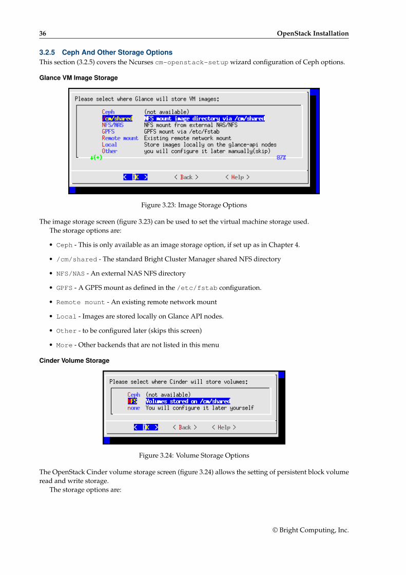
Figure 3.23: Image Storage Options
The image storage screen (figure 3.23) can be used to set the virtual machine storage used.The storage options are:
• Ceph - This is only available as an image storage option, if set up as in Chapter 4.
• /cm/shared - The standard Bright Cluster Manager shared NFS directory
• NFS/NAS - An external NAS NFS directory
• GPFS - A GPFS mount as defined in the /etc/fstab configuration.
• Remote mount - An existing remote network mount
• Local - Images are stored locally on Glance API nodes.
• Other - to be configured later (skips this screen)
• More - Other backends that are not listed in this menu
Cinder Volume Storage
Figure 3.24: Volume Storage Options
The OpenStack Cinder volume storage screen (figure 3.24) allows the setting of persistent block volumeread and write storage.
The storage options are:
© Bright Computing, Inc.

3.2 Installation Of OpenStack From The Shell 37
• Ceph - This is only available as a volume storage option, if set up as in Chapter 4. If set, it usesCeph’s RBD volume driver, and configures a “volume backup” driver to use Ceph.
• NFS - Storage is done on /cm/shared using the Cinder reference driver. This is not recommendedfor large-scale production use.
• None - to be configured later (skips this screen)
Root And Ephemeral Device Storage With Ceph
Figure 3.25: Root And Ephemeral Device Storage With Ceph
Data storage with Ceph can be enabled by the administrator by using the Ceph for OpenStack root andephemeral device storage screen (figure 3.25).
Ceph Object Gateway (Ceph RADOS Gateway)
Figure 3.26: Root And Ephemeral Device Storage With Ceph
The Ceph RADOS gateway screen (figure 3.26) lets the administrator set the Ceph RADOS gatewayservice to run when deployment completes.
© Bright Computing, Inc.
38 OpenStack Installation
3.2.6 Hypervisor Nodes Selection For OpenStack
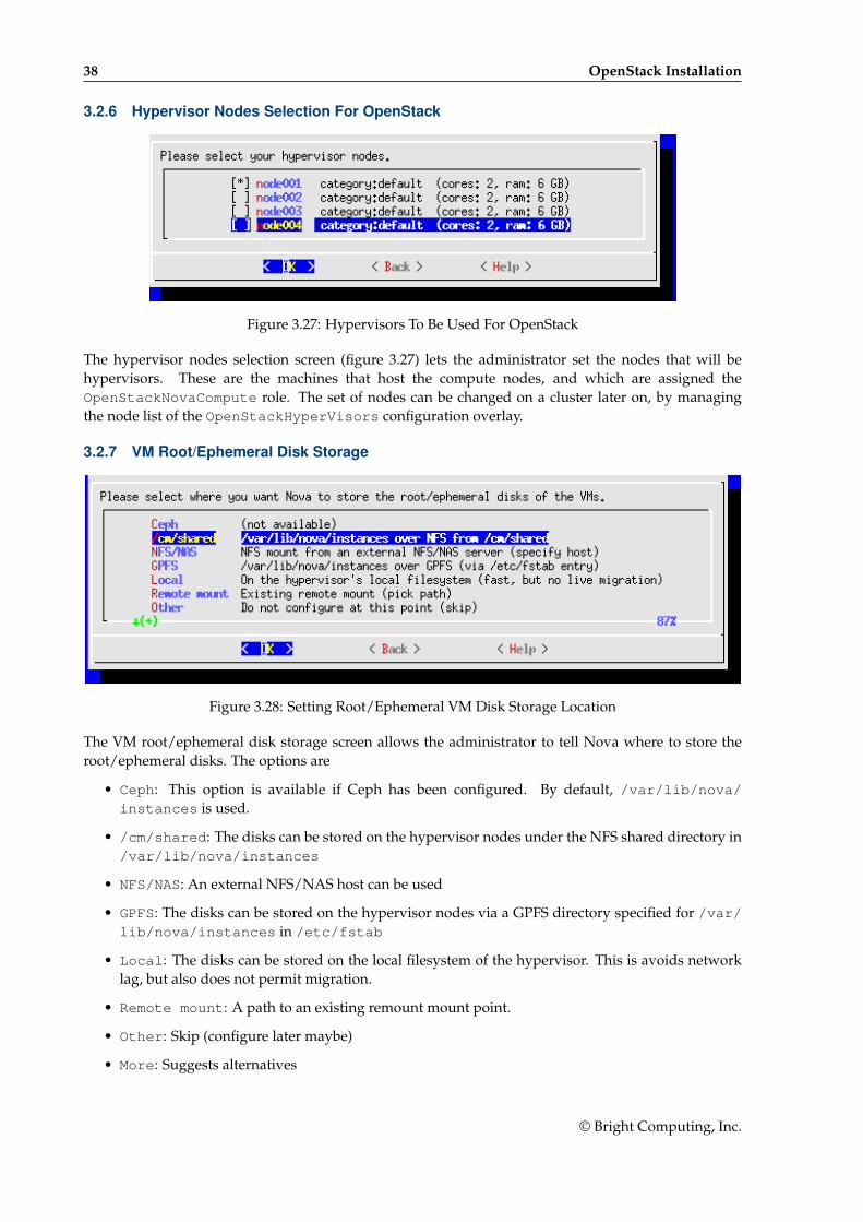
Figure 3.27: Hypervisors To Be Used For OpenStack
The hypervisor nodes selection screen (figure 3.27) lets the administrator set the nodes that will behypervisors. These are the machines that host the compute nodes, and which are assigned theOpenStackNovaCompute role. The set of nodes can be changed on a cluster later on, by managingthe node list of the OpenStackHyperVisors configuration overlay.
3.2.7 VM Root/Ephemeral Disk Storage
Figure 3.28: Setting Root/Ephemeral VM Disk Storage Location
The VM root/ephemeral disk storage screen allows the administrator to tell Nova where to store theroot/ephemeral disks. The options are
• Ceph: This option is available if Ceph has been configured. By default, /var/lib/nova/instances is used.
• /cm/shared: The disks can be stored on the hypervisor nodes under the NFS shared directory in/var/lib/nova/instances
• NFS/NAS: An external NFS/NAS host can be used
• GPFS: The disks can be stored on the hypervisor nodes via a GPFS directory specified for /var/lib/nova/instances in /etc/fstab
• Local: The disks can be stored on the local filesystem of the hypervisor. This is avoids networklag, but also does not permit migration.
• Remote mount: A path to an existing remount mount point.
• Other: Skip (configure later maybe)
• More: Suggests alternatives
© Bright Computing, Inc.
3.2 Installation Of OpenStack From The Shell 39
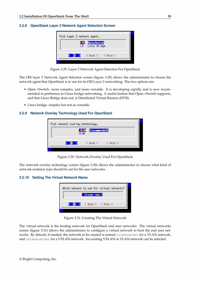
3.2.8 OpenStack Layer 2 Network Agent Selection Screen
Figure 3.29: Layer 2 Network Agent Selection For OpenStack
The OSI layer 2 Network Agent Selection screen (figure 3.29) allows the administrator to choose thenetwork agent that OpenStack is to use for its OSI Layer 2 networking. The two options are:
• Open vSwitch: more complex, and more versatile. It is developing rapidly and is now recom-mended in preference to Linux bridge networking. A useful feature that Open vSwitch supports,and that Linux Bridge does not, is Distributed Virtual Routers (DVR).
• Linux bridge: simpler, but not as versatile.
3.2.9 Network Overlay Technology Used For OpenStack
Figure 3.30: Network Overlay Used For OpenStack
The network overlay technology screen (figure 3.30) allows the administrator to choose what kind ofnetwork isolation type should be set for the user networks.
3.2.10 Setting The Virtual Network Name
Figure 3.31: Creating The Virtual Network
The virtual network is the hosting network for OpenStack end user networks. The virtual networksscreen (figure 3.31) allows the administrator to configure a virtual network to host the end user net-works. By default, if needed, the network to be created is named vlanhostnet for a VLAN network,and vxlanhostnet for a VXLAN network. An existing VXLAN or VLAN network can be selected.
© Bright Computing, Inc.
40 OpenStack Installation
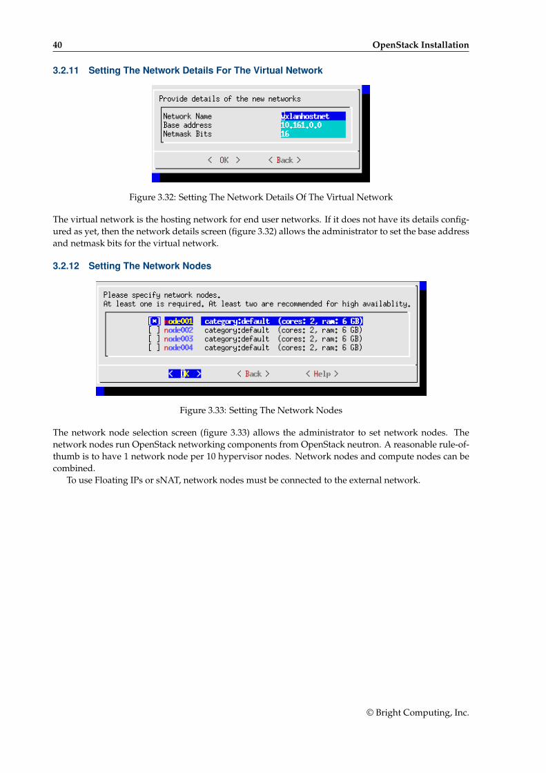
3.2.11 Setting The Network Details For The Virtual Network
Figure 3.32: Setting The Network Details Of The Virtual Network
The virtual network is the hosting network for end user networks. If it does not have its details config-ured as yet, then the network details screen (figure 3.32) allows the administrator to set the base addressand netmask bits for the virtual network.
3.2.12 Setting The Network Nodes
Figure 3.33: Setting The Network Nodes
The network node selection screen (figure 3.33) allows the administrator to set network nodes. Thenetwork nodes run OpenStack networking components from OpenStack neutron. A reasonable rule-of-thumb is to have 1 network node per 10 hypervisor nodes. Network nodes and compute nodes can becombined.
To use Floating IPs or sNAT, network nodes must be connected to the external network.
© Bright Computing, Inc.
3.2 Installation Of OpenStack From The Shell 41
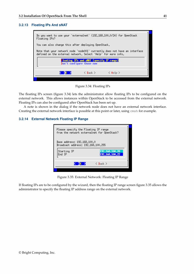
3.2.13 Floating IPs And sNAT
Figure 3.34: Floating IPs
The floating IPs screen (figure 3.34) lets the administrator allow floating IPs to be configured on theexternal network. This allows instances within OpenStack to be accessed from the external network.Floating IPs can also be configured after OpenStack has been set up.
A note is shown in the dialog if the network node does not have an external network interface.Creating the external network interface is possible at this point or later, using cmsh for example.
3.2.14 External Network Floating IP Range
Figure 3.35: External Network: Floating IP Range
If floating IPs are to be configured by the wizard, then the floating IP range screen figure 3.35 allows theadministrator to specify the floating IP address range on the external network.
© Bright Computing, Inc.
42 OpenStack Installation
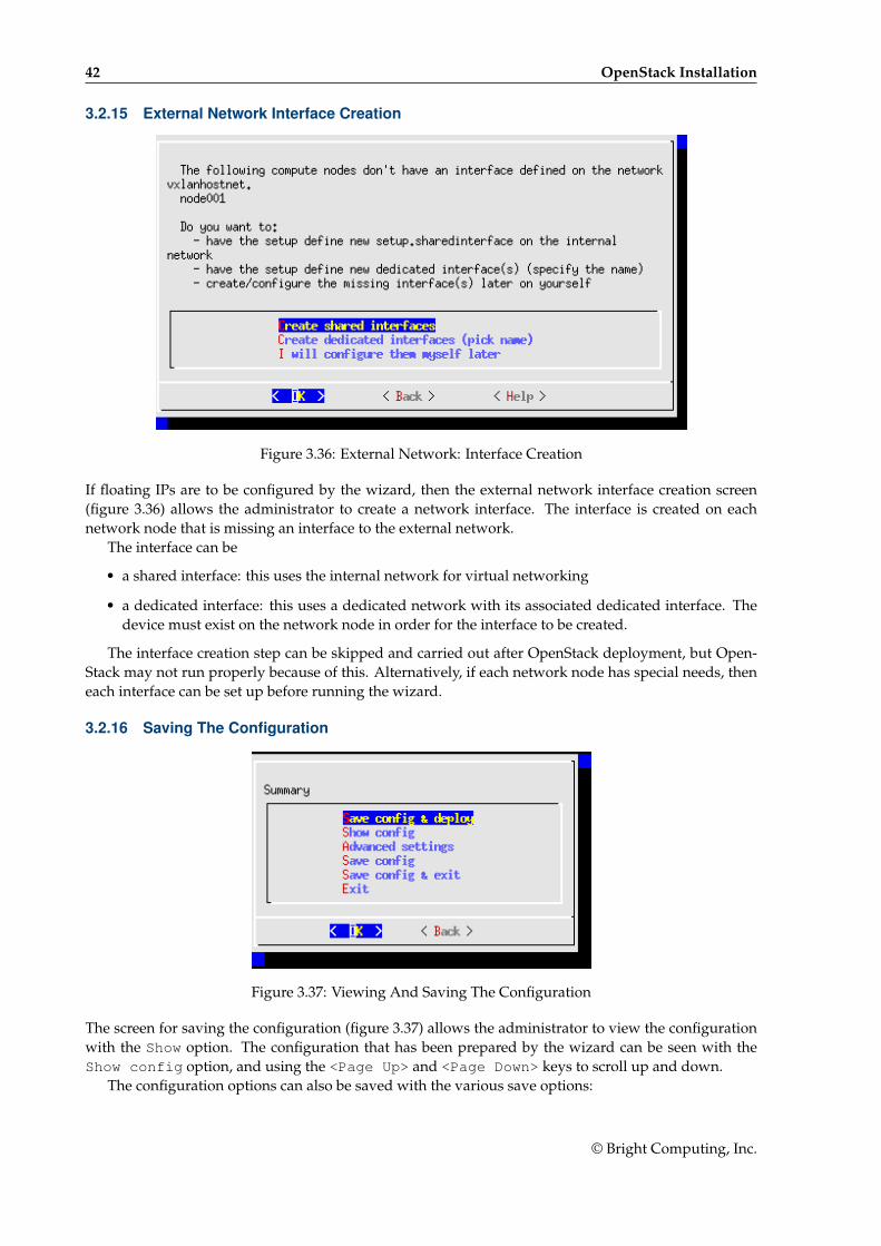
3.2.15 External Network Interface Creation
Figure 3.36: External Network: Interface Creation
If floating IPs are to be configured by the wizard, then the external network interface creation screen(figure 3.36) allows the administrator to create a network interface. The interface is created on eachnetwork node that is missing an interface to the external network.
The interface can be
• a shared interface: this uses the internal network for virtual networking
• a dedicated interface: this uses a dedicated network with its associated dedicated interface. Thedevice must exist on the network node in order for the interface to be created.
The interface creation step can be skipped and carried out after OpenStack deployment, but Open-Stack may not run properly because of this. Alternatively, if each network node has special needs, theneach interface can be set up before running the wizard.
3.2.16 Saving The Configuration
Figure 3.37: Viewing And Saving The Configuration
The screen for saving the configuration (figure 3.37) allows the administrator to view the configurationwith the Show option. The configuration that has been prepared by the wizard can be seen with theShow config option, and using the <Page Up> and <Page Down> keys to scroll up and down.
The configuration options can also be saved with the various save options:
© Bright Computing, Inc.
3.2 Installation Of OpenStack From The Shell 43
• Save config & deploy: Saves, and after saving carries out the text-based deployment stage ofthe installation.
• Save: Saves, and stays within the Ncurses dialog. The deployment can be carried out later from asaved configuration.
• Save config & exit: Saves, and then exits the Ncurses dialog. The deployment can be carriedout later from a saved configuration.
Saving saves the configration as a YAML configuration file, by default cm-openstack-setup.conf,in the directory under which the wizard is running. This file can be used as the input configuration filefor the cm-openstack-setup utility using the -c option.
Most administrators run Save config & deploy, and the deployment run takes place (sec-tion 3.2.17). Some administrators may however wish to modify some OpenStack component settings.
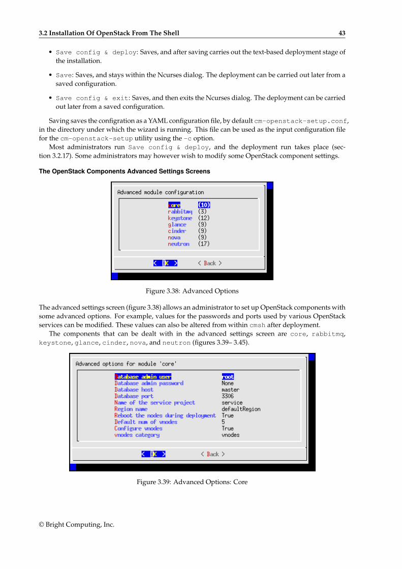
The OpenStack Components Advanced Settings Screens
Figure 3.38: Advanced Options
The advanced settings screen (figure 3.38) allows an administrator to set up OpenStack components withsome advanced options. For example, values for the passwords and ports used by various OpenStackservices can be modified. These values can also be altered from within cmsh after deployment.
The components that can be dealt with in the advanced settings screen are core, rabbitmq,keystone, glance, cinder, nova, and neutron (figures 3.39– 3.45).
Figure 3.39: Advanced Options: Core
© Bright Computing, Inc.
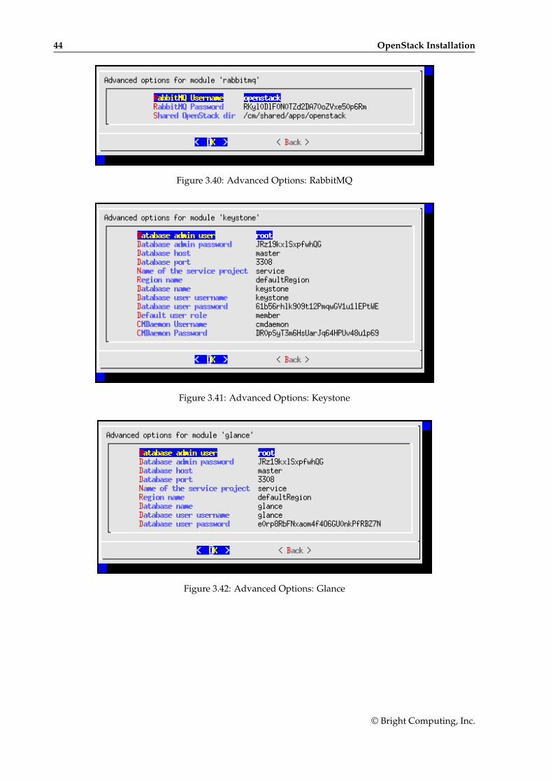
44 OpenStack Installation
Figure 3.40: Advanced Options: RabbitMQ
Figure 3.41: Advanced Options: Keystone
Figure 3.42: Advanced Options: Glance
© Bright Computing, Inc.
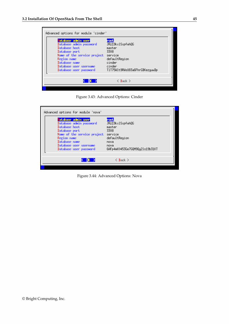
3.2 Installation Of OpenStack From The Shell 45
Figure 3.43: Advanced Options: Cinder
Figure 3.44: Advanced Options: Nova
© Bright Computing, Inc.
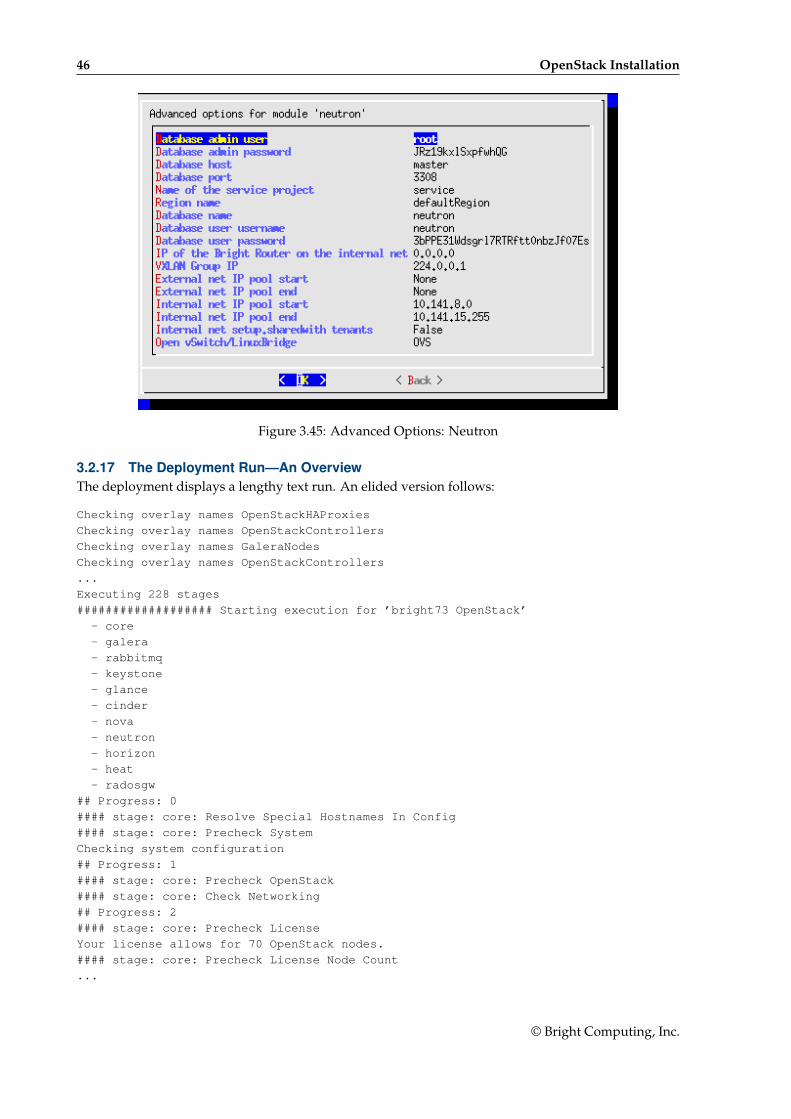
46 OpenStack Installation
Figure 3.45: Advanced Options: Neutron
3.2.17 The Deployment Run—An OverviewThe deployment displays a lengthy text run. An elided version follows:
Checking overlay names OpenStackHAProxies
Checking overlay names OpenStackControllers
Checking overlay names GaleraNodes
Checking overlay names OpenStackControllers
...
Executing 228 stages
################### Starting execution for ’bright73 OpenStack’
- core
- galera
- rabbitmq
- keystone
- glance
- cinder
- nova
- neutron
- horizon
- heat
- radosgw
## Progress: 0
#### stage: core: Resolve Special Hostnames In Config
#### stage: core: Precheck System
Checking system configuration
## Progress: 1
#### stage: core: Precheck OpenStack
#### stage: core: Check Networking
## Progress: 2
#### stage: core: Precheck License
Your license allows for 70 OpenStack nodes.
#### stage: core: Precheck License Node Count
...
© Bright Computing, Inc.
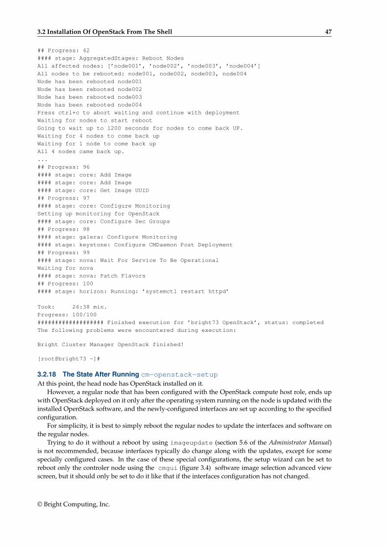
3.2 Installation Of OpenStack From The Shell 47
## Progress: 42
#### stage: AggregatedStages: Reboot Nodes
All affected nodes: [’node001’, ’node002’, ’node003’, ’node004’]
All nodes to be rebooted: node001, node002, node003, node004
Node has been rebooted node001
Node has been rebooted node002
Node has been rebooted node003
Node has been rebooted node004
Press ctrl+c to abort waiting and continue with deployment
Waiting for nodes to start reboot
Going to wait up to 1200 seconds for nodes to come back UP.
Waiting for 4 nodes to come back up
Waiting for 1 node to come back up
All 4 nodes came back up.
...
## Progress: 96
#### stage: core: Add Image
#### stage: core: Add Image
#### stage: core: Get Image UUID
## Progress: 97
#### stage: core: Configure Monitoring
Setting up monitoring for OpenStack
#### stage: core: Configure Sec Groups
## Progress: 98
#### stage: galera: Configure Monitoring
#### stage: keystone: Configure CMDaemon Post Deployment
## Progress: 99
#### stage: nova: Wait For Service To Be Operational
Waiting for nova
#### stage: nova: Patch Flavors
## Progress: 100
#### stage: horizon: Running: ’systemctl restart httpd’
Took: 26:38 min.
Progress: 100/100
################### Finished execution for ’bright73 OpenStack’, status: completed
The following problems were encountered during execution:
Bright Cluster Manager OpenStack finished!
[root@bright73 ~]#
3.2.18 The State After Running cm-openstack-setupAt this point, the head node has OpenStack installed on it.
However, a regular node that has been configured with the OpenStack compute host role, ends upwith OpenStack deployed on it only after the operating system running on the node is updated with theinstalled OpenStack software, and the newly-configured interfaces are set up according to the specifiedconfiguration.
For simplicity, it is best to simply reboot the regular nodes to update the interfaces and software onthe regular nodes.
Trying to do it without a reboot by using imageupdate (section 5.6 of the Administrator Manual)is not recommended, because interfaces typically do change along with the updates, except for somespecially configured cases. In the case of these special configurations, the setup wizard can be set toreboot only the controler node using the cmgui (figure 3.4) software image selection advanced viewscreen, but it should only be set to do it like that if the interfaces configuration has not changed.
© Bright Computing, Inc.
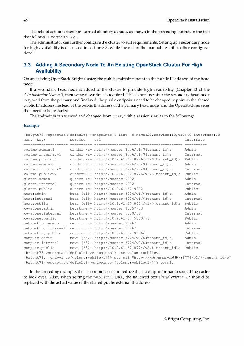
48 OpenStack Installation
The reboot action is therefore carried about by default, as shown in the preceding output, in the textthat follows “Progress 42”.
The administrator can further configure the cluster to suit requirements. Setting up a secondary nodefor high availability is discussed in section 3.3, while the rest of the manual describes other configura-tions.
3.3 Adding A Secondary Node To An Existing OpenStack Cluster For HighAvailability
On an existing OpenStack Bright cluster, the public endpoints point to the public IP address of the headnode.
If a secondary head node is added to the cluster to provide high availability (Chapter 13 of theAdministrator Manual), then some downtime is required. This is because after the secondary head nodeis synced from the primary and finalized, the public endpoints need to be changed to point to the sharedpublic IP address, instead of the public IP address of the primary head node, and the OpenStack servicesthen need to be restarted.
The endpoints can viewed and changed from cmsh, with a session similar to the following:
Example
[bright73->openstack[default]->endpoints]% list -f name:20,service:10,url:40,interface:10
name (key) service url interface
-------------------- ---------- ---------------------------------------- ----------
volume:adminv1 cinder (a+ http://master:8776/v1/$(tenant_id)s Admin
volume:internalv1 cinder (a+ http://master:8776/v1/$(tenant_id)s Internal
volume:publicv1 cinder (a+ http://10.2.61.67:8776/v1/$(tenant_id)s Public
volume:adminv2 cinderv2 + http://master:8776/v2/$(tenant_id)s Admin
volume:internalv2 cinderv2 + http://master:8776/v2/$(tenant_id)s Internal
volume:publicv2 cinderv2 + http://10.2.61.67:8776/v2/$(tenant_id)s Public
glance:admin glance (c+ http://master:9292 Admin
glance:internal glance (c+ http://master:9292 Internal
glance:public glance (c+ http://10.2.61.67:9292 Public
heat:admin heat (e19+ http://master:8004/v1/$(tenant_id)s Admin
heat:internal heat (e19+ http://master:8004/v1/$(tenant_id)s Internal
heat:public heat (e19+ http://10.2.61.67:8004/v1/$(tenant_id)s Public
keystone:admin keystone + http://master:35357/v3 Admin
keystone:internal keystone + http://master:5000/v3 Internal
keystone:public keystone + http://10.2.61.67:5000/v3 Public
networking:admin neutron (+ http://master:9696/ Admin
networking:internal neutron (+ http://master:9696/ Internal
networking:public neutron (+ http://10.2.61.67:9696/ Public
compute:admin nova (632+ http://master:8774/v2/$(tenant_id)s Admin
compute:internal nova (632+ http://master:8774/v2/$(tenant_id)s Internal
compute:public nova (632+ http://10.2.61.67:8774/v2/$(tenant_id)s Public
[bright73->openstack[default]->endpoints]% use volume:publicv1
[bright73...endpoints[volume:publicv1]]% set url "http://<shared external IP>:8776/v2/$(tenant_id)s"[bright73->openstack[default]->endpoints*[volume:publicv1*]]% commit
In the preceding example, the -f option is used to reduce the list output format to something easierto look over. Also, when setting the publicv1 URL, the italicized text shared external IP should bereplaced with the actual value of the shared public external IP address.
© Bright Computing, Inc.

4Ceph Installation
4.1 Ceph IntroductionCeph, at the time of writing, is the recommended storage software for OpenStack for serious use. TheCeph RADOS Gateway is a drop-in replacement for Swift, with a compatible API. Ceph is the recom-mended backend driver for Cinder, Glance and Nova.
The current chapter discusses
• The concepts and required hardware for Ceph (section 4.1)
• Ceph installation and management (section 4.2)
• RADOS GW installation and management (section 4.4)
4.1.1 Ceph Object And Block StorageCeph is a distributed storage software. It is based on an object store layer called RADOS (ReliableAutonomic Distributed Object Store), which consists of Ceph components called OSDs (Object StorageDevices) and MONs (Monitoring Servers). These components feature heavily in Ceph. OSDs deal withstoring the objects to a device, while MONs deal with mapping the cluster. OSDs and MONs, togethercarry out object storage and block storage within the object store layer. The stack diagram of figure 4.1illustrates these concepts.
© Bright Computing, Inc.
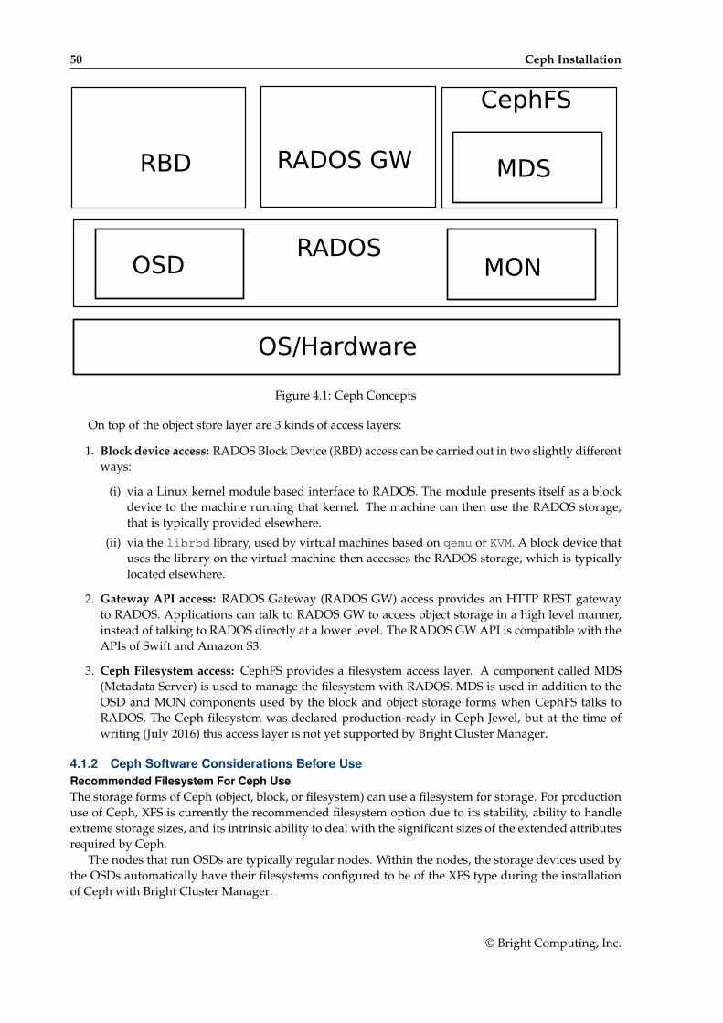
50 Ceph Installation
RADOSOSD MON
RBD RADOS GW
CephFS
MDS
OS/Hardware
Figure 4.1: Ceph Concepts
On top of the object store layer are 3 kinds of access layers:
1. Block device access: RADOS Block Device (RBD) access can be carried out in two slightly differentways:
(i) via a Linux kernel module based interface to RADOS. The module presents itself as a blockdevice to the machine running that kernel. The machine can then use the RADOS storage,that is typically provided elsewhere.
(ii) via the librbd library, used by virtual machines based on qemu or KVM. A block device thatuses the library on the virtual machine then accesses the RADOS storage, which is typicallylocated elsewhere.
2. Gateway API access: RADOS Gateway (RADOS GW) access provides an HTTP REST gatewayto RADOS. Applications can talk to RADOS GW to access object storage in a high level manner,instead of talking to RADOS directly at a lower level. The RADOS GW API is compatible with theAPIs of Swift and Amazon S3.
3. Ceph Filesystem access: CephFS provides a filesystem access layer. A component called MDS(Metadata Server) is used to manage the filesystem with RADOS. MDS is used in addition to theOSD and MON components used by the block and object storage forms when CephFS talks toRADOS. The Ceph filesystem was declared production-ready in Ceph Jewel, but at the time ofwriting (July 2016) this access layer is not yet supported by Bright Cluster Manager.
4.1.2 Ceph Software Considerations Before UseRecommended Filesystem For Ceph UseThe storage forms of Ceph (object, block, or filesystem) can use a filesystem for storage. For productionuse of Ceph, XFS is currently the recommended filesystem option due to its stability, ability to handleextreme storage sizes, and its intrinsic ability to deal with the significant sizes of the extended attributesrequired by Ceph.
The nodes that run OSDs are typically regular nodes. Within the nodes, the storage devices used bythe OSDs automatically have their filesystems configured to be of the XFS type during the installationof Ceph with Bright Cluster Manager.
© Bright Computing, Inc.

4.1 Ceph Introduction 51
Use Of datanode For Protection Of OSD DataTypically, a filesystem used for an OSD is not on the same device as that of the regular node filesystem.Instead, typically, OSD storage consists of several devices that contain an XFS filesytem, with the devicesattached to the node. These devices need protection from being wiped during the reprovisioning thattakes place during a reboot of regular nodes .
The recommended way to protect storage devices from being wiped is to set the datanode propertyof their node to yes (page 180 of the Administrator Manual).
Use Of Slurm On OSD NodesCeph can be quite demanding of the network and I/O. Running Slurm jobs on an OSD node is thereforenot recommended. In addition, if Slurm roles are to be assigned to nodes that have OSD roles, then thedefault ports 6817 and 6818 used by Slurm can conflict with the default range 6800-7300 used by theCeph OSD daemons. If there is a need to run Slurm on an OSD node then it is necessary to arrange itso that the ports used do not conflict with each other. During installation, a warning is given when thisconflict is present.
4.1.3 Hardware For Ceph UseAn absolute minimum installation: can be carried out on two nodes, where:
• 1 node, the head node, runs one Ceph Monitor and the first OSD.
• 1 node, the regular node, runs the second OSD.
This is however not currently recommended, because the first OSD on the head node requires its ownCeph-compatible filesystem. If that filesystem is not provided, then Ceph on the cluster will run, butin a degraded state. Using such a system to try to get familiar with how Ceph behaves in a productionenvironment with Bright Cluster Manager is unlikely to be worthwhile.
A more useful minimum: if there is a node to spare, installing Ceph over 3 nodes is suggested, where:
• 1 node, the head node, runs one Ceph Monitor.
• 1 node, the regular node, runs the first OSD.
• 1 more node, also a regular node, runs the second OSD.
In this case the OSD pool default size should be set to 2 in the Global OSD Settings (figure 4.8).
For production use: a redundant number of Ceph Monitor servers is recommended. Since the numberof Ceph Monitoring servers must be odd, then at least 3 Ceph Monitor servers, with each on a separatenode, are recommended for production purposes. The recommended minimum of nodes for productionpurposes is then 5:
• 2 regular nodes running OSDs.
• 2 regular nodes running Ceph Monitors.
• 1 head node running a Ceph Monitor.
Drives usable by Ceph: Ceph OSDs can use any type of disk that presents itself as a block device inLinux. This means that a variety of drives can be used.
© Bright Computing, Inc.
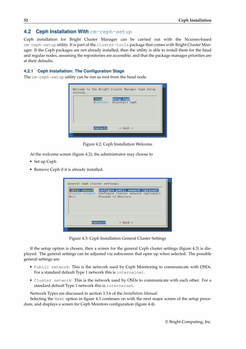
52 Ceph Installation
4.2 Ceph Installation With cm-ceph-setup
Ceph installation for Bright Cluster Manager can be carried out with the Ncurses-basedcm-ceph-setup utility. It is part of the cluster-tools package that comes with Bright Cluster Man-ager. If the Ceph packages are not already installed, then the utility is able to install them for the headand regular nodes, assuming the repositories are accessible, and that the package manager priorities areat their defaults.
4.2.1 Ceph Installation: The Configuration StageThe cm-ceph-setup utility can be run as root from the head node.
Figure 4.2: Ceph Installation Welcome
At the welcome screen (figure 4.2), the administrator may choose to
• Set up Ceph
• Remove Ceph if it is already installed.
Figure 4.3: Ceph Installation General Cluster Settings
If the setup option is chosen, then a screen for the general Ceph cluster settings (figure 4.3) is dis-played. The general settings can be adjusted via subscreens that open up when selected. The possiblegeneral settings are:
• Public network: This is the network used by Ceph Monitoring to communicate with OSDs.For a standard default Type 1 network this is internalnet.
• Cluster network: This is the network used by OSDs to communicate with each other. For astandard default Type 1 network this is internalnet.
Network Types are discussed in section 3.3.6 of the Installation Manual.Selecting the Next option in figure 4.3 continues on with the next major screen of the setup proce-
dure, and displays a screen for Ceph Monitors configuration (figure 4.4).
© Bright Computing, Inc.
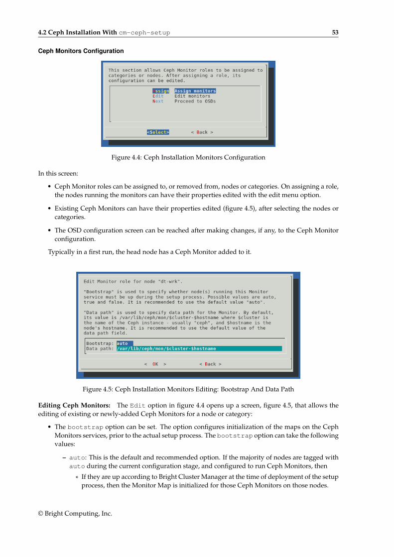
4.2 Ceph Installation With cm-ceph-setup 53
Ceph Monitors Configuration
Figure 4.4: Ceph Installation Monitors Configuration
In this screen:
• Ceph Monitor roles can be assigned to, or removed from, nodes or categories. On assigning a role,the nodes running the monitors can have their properties edited with the edit menu option.
• Existing Ceph Monitors can have their properties edited (figure 4.5), after selecting the nodes orcategories.
• The OSD configuration screen can be reached after making changes, if any, to the Ceph Monitorconfiguration.
Typically in a first run, the head node has a Ceph Monitor added to it.
Figure 4.5: Ceph Installation Monitors Editing: Bootstrap And Data Path
Editing Ceph Monitors: The Edit option in figure 4.4 opens up a screen, figure 4.5, that allows theediting of existing or newly-added Ceph Monitors for a node or category:
• The bootstrap option can be set. The option configures initialization of the maps on the CephMonitors services, prior to the actual setup process. The bootstrap option can take the followingvalues:
– auto: This is the default and recommended option. If the majority of nodes are tagged withauto during the current configuration stage, and configured to run Ceph Monitors, then
* If they are up according to Bright Cluster Manager at the time of deployment of the setupprocess, then the Monitor Map is initialized for those Ceph Monitors on those nodes.
© Bright Computing, Inc.
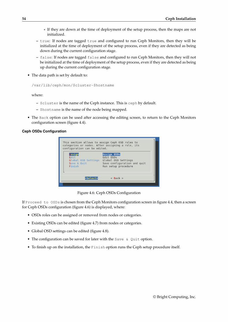
54 Ceph Installation
* If they are down at the time of deployment of the setup process, then the maps are notinitialized.
– true: If nodes are tagged true and configured to run Ceph Monitors, then they will beinitialized at the time of deployment of the setup process, even if they are detected as beingdown during the current configuration stage.
– false: If nodes are tagged false and configured to run Ceph Monitors, then they will notbe initialized at the time of deployment of the setup process, even if they are detected as beingup during the current configuration stage.
• The data path is set by default to:
/var/lib/ceph/mon/$cluster-$hostname
where:
– $cluster is the name of the Ceph instance. This is ceph by default.
– $hostname is the name of the node being mapped.
• The Back option can be used after accessing the editing screen, to return to the Ceph Monitorsconfiguration screen (figure 4.4).
Ceph OSDs Configuration
Figure 4.6: Ceph OSDs Configuration
If Proceed to OSDs is chosen from the Ceph Monitors configuration screen in figure 4.4, then a screenfor Ceph OSDs configuration (figure 4.6) is displayed, where:
• OSDs roles can be assigned or removed from nodes or categories.
• Existing OSDs can be edited (figure 4.7) from nodes or categories.
• Global OSD settings can be edited (figure 4.8).
• The configuration can be saved for later with the Save & Quit option.
• To finish up on the installation, the Finish option runs the Ceph setup procedure itself.
© Bright Computing, Inc.
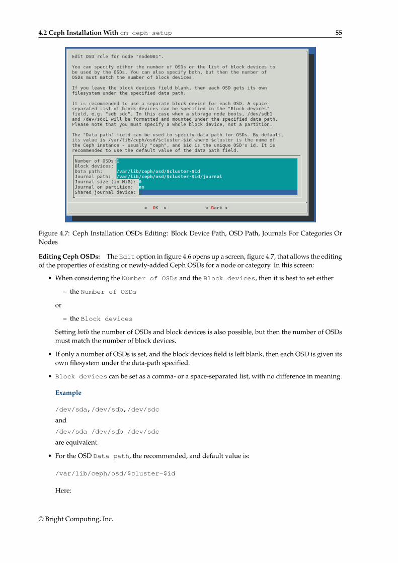
4.2 Ceph Installation With cm-ceph-setup 55
Figure 4.7: Ceph Installation OSDs Editing: Block Device Path, OSD Path, Journals For Categories OrNodes
Editing Ceph OSDs: The Edit option in figure 4.6 opens up a screen, figure 4.7, that allows the editingof the properties of existing or newly-added Ceph OSDs for a node or category. In this screen:
• When considering the Number of OSDs and the Block devices, then it is best to set either
– the Number of OSDs
or
– the Block devices
Setting both the number of OSDs and block devices is also possible, but then the number of OSDsmust match the number of block devices.
• If only a number of OSDs is set, and the block devices field is left blank, then each OSD is given itsown filesystem under the data-path specified.
• Block devices can be set as a comma- or a space-separated list, with no difference in meaning.
Example
/dev/sda,/dev/sdb,/dev/sdc
and
/dev/sda /dev/sdb /dev/sdc
are equivalent.
• For the OSD Data path, the recommended, and default value is:
/var/lib/ceph/osd/$cluster-$id
Here:
© Bright Computing, Inc.
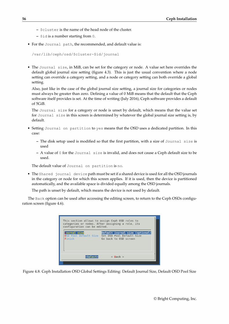
56 Ceph Installation
– $cluster is the name of the head node of the cluster.
– $id is a number starting from 0.
• For the Journal path, the recommended, and default value is:
/var/lib/ceph/osd/$cluster-$id/journal
• The Journal size, in MiB, can be set for the category or node. A value set here overrides thedefault global journal size setting (figure 4.3). This is just the usual convention where a nodesetting can override a category setting, and a node or category setting can both override a globalsetting.
Also, just like in the case of the global journal size setting, a journal size for categories or nodesmust always be greater than zero. Defining a value of 0 MiB means that the default that the Cephsoftware itself provides is set. At the time of writing (July 2016), Ceph software provides a defaultof 5GiB.
The Journal size for a category or node is unset by default, which means that the value setfor Journal size in this screen is determined by whatever the global journal size setting is, bydefault.
• Setting Journal on partition to yes means that the OSD uses a dedicated partition. In thiscase:
– The disk setup used is modified so that the first partition, with a size of Journal size isused
– A value of 0 for the Journal size is invalid, and does not cause a Ceph default size to beused.
The default value of Journal on partition is no.
• The Shared journal device path must be set if a shared device is used for all the OSD journalsin the category or node for which this screen applies. If it is used, then the device is partitionedautomatically, and the available space is divided equally among the OSD journals.
The path is unset by default, which means the device is not used by default.
The Back option can be used after accessing the editing screen, to return to the Ceph OSDs configu-ration screen (figure 4.6).
Figure 4.8: Ceph Installation OSD Global Settings Editing: Default Journal Size, Default OSD Pool Size
© Bright Computing, Inc.
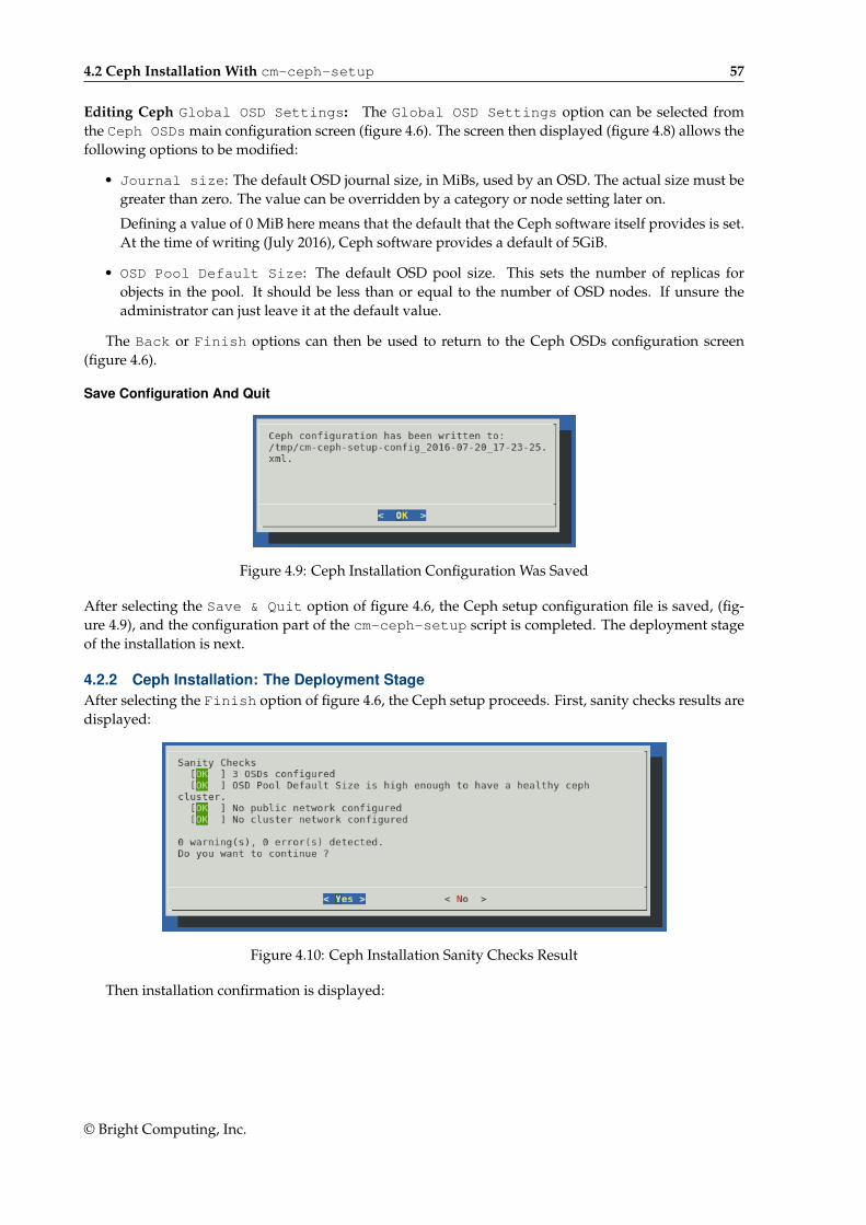
4.2 Ceph Installation With cm-ceph-setup 57
Editing Ceph Global OSD Settings: The Global OSD Settings option can be selected fromthe Ceph OSDs main configuration screen (figure 4.6). The screen then displayed (figure 4.8) allows thefollowing options to be modified:
• Journal size: The default OSD journal size, in MiBs, used by an OSD. The actual size must begreater than zero. The value can be overridden by a category or node setting later on.
Defining a value of 0 MiB here means that the default that the Ceph software itself provides is set.At the time of writing (July 2016), Ceph software provides a default of 5GiB.
• OSD Pool Default Size: The default OSD pool size. This sets the number of replicas forobjects in the pool. It should be less than or equal to the number of OSD nodes. If unsure theadministrator can just leave it at the default value.
The Back or Finish options can then be used to return to the Ceph OSDs configuration screen(figure 4.6).
Save Configuration And Quit
Figure 4.9: Ceph Installation Configuration Was Saved
After selecting the Save & Quit option of figure 4.6, the Ceph setup configuration file is saved, (fig-ure 4.9), and the configuration part of the cm-ceph-setup script is completed. The deployment stageof the installation is next.
4.2.2 Ceph Installation: The Deployment StageAfter selecting the Finish option of figure 4.6, the Ceph setup proceeds. First, sanity checks results aredisplayed:
Figure 4.10: Ceph Installation Sanity Checks Result
Then installation confirmation is displayed:
© Bright Computing, Inc.
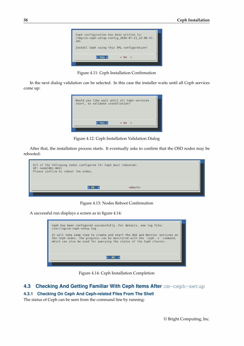
58 Ceph Installation
Figure 4.11: Ceph Installation Confirmation
In the next dialog validation can be selected. In this case the installer waits until all Ceph servicescome up:
Figure 4.12: Ceph Installation Validation Dialog
After that, the installation process starts. It eventually asks to confirm that the OSD nodes may berebooted:
Figure 4.13: Nodes Reboot Confirmation
A successful run displays a screen as in figure 4.14:
Figure 4.14: Ceph Installation Completion
4.3 Checking And Getting Familiar With Ceph Items After cm-ceph-setup4.3.1 Checking On Ceph And Ceph-related Files From The ShellThe status of Ceph can be seen from the command line by running:
© Bright Computing, Inc.
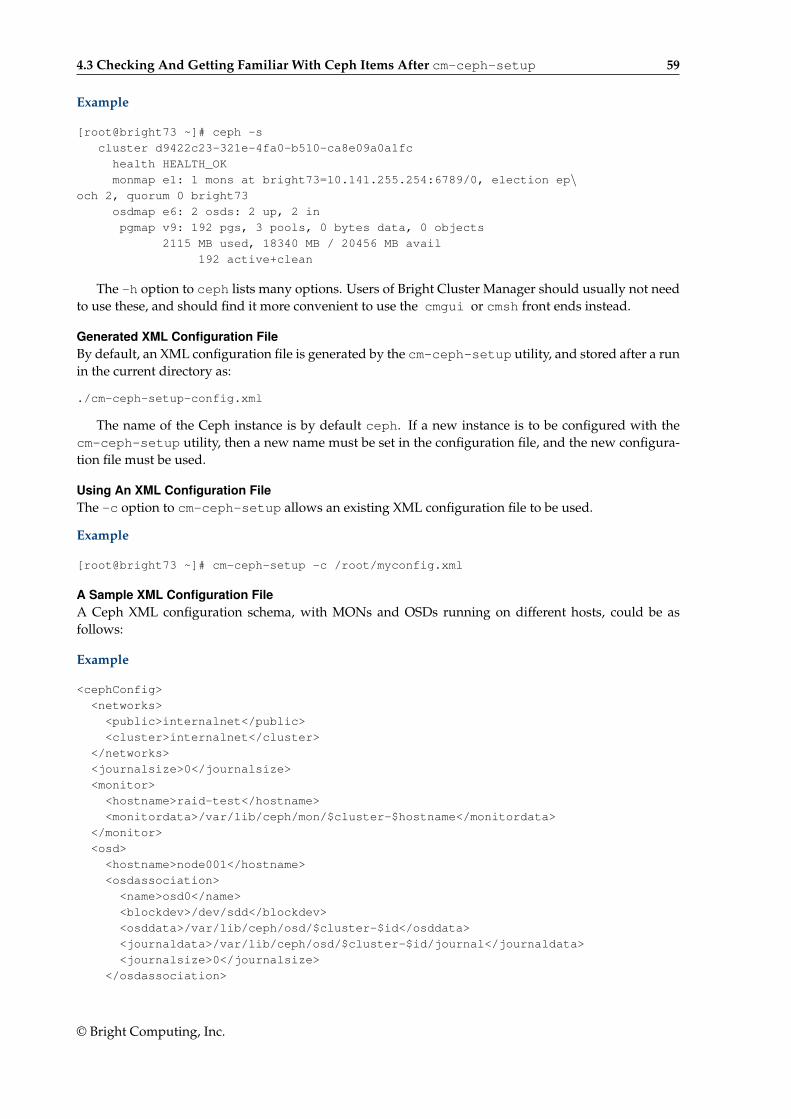
4.3 Checking And Getting Familiar With Ceph Items After cm-ceph-setup 59
Example
[root@bright73 ~]# ceph -s
cluster d9422c23-321e-4fa0-b510-ca8e09a0a1fc
health HEALTH_OK
monmap e1: 1 mons at bright73=10.141.255.254:6789/0, election ep\och 2, quorum 0 bright73
osdmap e6: 2 osds: 2 up, 2 in
pgmap v9: 192 pgs, 3 pools, 0 bytes data, 0 objects
2115 MB used, 18340 MB / 20456 MB avail
192 active+clean
The -h option to ceph lists many options. Users of Bright Cluster Manager should usually not needto use these, and should find it more convenient to use the cmgui or cmsh front ends instead.
Generated XML Configuration FileBy default, an XML configuration file is generated by the cm-ceph-setup utility, and stored after a runin the current directory as:
./cm-ceph-setup-config.xml
The name of the Ceph instance is by default ceph. If a new instance is to be configured with thecm-ceph-setup utility, then a new name must be set in the configuration file, and the new configura-tion file must be used.
Using An XML Configuration FileThe -c option to cm-ceph-setup allows an existing XML configuration file to be used.
Example
[root@bright73 ~]# cm-ceph-setup -c /root/myconfig.xml
A Sample XML Configuration FileA Ceph XML configuration schema, with MONs and OSDs running on different hosts, could be asfollows:
Example
<cephConfig>
<networks>
<public>internalnet</public>
<cluster>internalnet</cluster>
</networks>
<journalsize>0</journalsize>
<monitor>
<hostname>raid-test</hostname>
<monitordata>/var/lib/ceph/mon/$cluster-$hostname</monitordata>
</monitor>
<osd>
<hostname>node001</hostname>
<osdassociation>
<name>osd0</name>
<blockdev>/dev/sdd</blockdev>
<osddata>/var/lib/ceph/osd/$cluster-$id</osddata>
<journaldata>/var/lib/ceph/osd/$cluster-$id/journal</journaldata>
<journalsize>0</journalsize>
</osdassociation>
© Bright Computing, Inc.
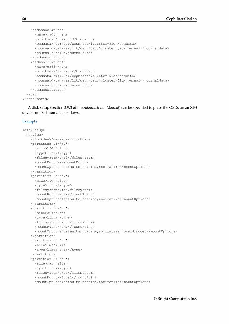
60 Ceph Installation
<osdassociation>
<name>osd1</name>
<blockdev>/dev/sde</blockdev>
<osddata>/var/lib/ceph/osd/$cluster-$id</osddata>
<journaldata>/var/lib/ceph/osd/$cluster-$id/journal</journaldata>
<journalsize>0</journalsize>
</osdassociation>
<osdassociation>
<name>osd2</name>
<blockdev>/dev/sdf</blockdev>
<osddata>/var/lib/ceph/osd/$cluster-$id</osddata>
<journaldata>/var/lib/ceph/osd/$cluster-$id/journal</journaldata>
<journalsize>0</journalsize>
</osdassociation>
</osd>
</cephConfig>
A disk setup (section 3.9.3 of the Administrator Manual) can be specified to place the OSDs on an XFSdevice, on partition a2 as follows:
Example
<diskSetup>
<device>
<blockdev>/dev/sda</blockdev>
<partition id="a1">
<size>10G</size>
<type>linux</type>
<filesystem>ext3</filesystem>
<mountPoint>/</mountPoint>
<mountOptions>defaults,noatime,nodiratime</mountOptions>
</partition>
<partition id="a2">
<size>10G</size>
<type>linux</type>
<filesystem>xfs</filesystem>
<mountPoint>/var</mountPoint>
<mountOptions>defaults,noatime,nodiratime</mountOptions>
</partition>
<partition id="a3">
<size>2G</size>
<type>linux</type>
<filesystem>ext3</filesystem>
<mountPoint>/tmp</mountPoint>
<mountOptions>defaults,noatime,nodiratime,nosuid,nodev</mountOptions>
</partition>
<partition id="a4">
<size>1G</size>
<type>linux swap</type>
</partition>
<partition id="a5">
<size>max</size>
<type>linux</type>
<filesystem>ext3</filesystem>
<mountPoint>/local</mountPoint>
<mountOptions>defaults,noatime,nodiratime</mountOptions>
© Bright Computing, Inc.
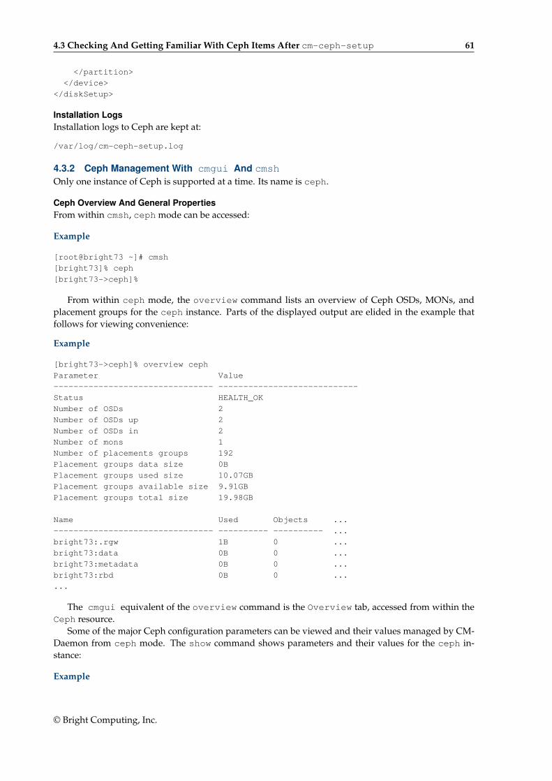
4.3 Checking And Getting Familiar With Ceph Items After cm-ceph-setup 61
</partition>
</device>
</diskSetup>
Installation LogsInstallation logs to Ceph are kept at:
/var/log/cm-ceph-setup.log
4.3.2 Ceph Management With cmgui And cmshOnly one instance of Ceph is supported at a time. Its name is ceph.
Ceph Overview And General PropertiesFrom within cmsh, ceph mode can be accessed:
Example
[root@bright73 ~]# cmsh
[bright73]% ceph
[bright73->ceph]%
From within ceph mode, the overview command lists an overview of Ceph OSDs, MONs, andplacement groups for the ceph instance. Parts of the displayed output are elided in the example thatfollows for viewing convenience:
Example
[bright73->ceph]% overview ceph
Parameter Value
-------------------------------- ----------------------------
Status HEALTH_OK
Number of OSDs 2
Number of OSDs up 2
Number of OSDs in 2
Number of mons 1
Number of placements groups 192
Placement groups data size 0B
Placement groups used size 10.07GB
Placement groups available size 9.91GB
Placement groups total size 19.98GB
Name Used Objects ...
-------------------------------- ---------- ---------- ...
bright73:.rgw 1B 0 ...
bright73:data 0B 0 ...
bright73:metadata 0B 0 ...
bright73:rbd 0B 0 ...
...
The cmgui equivalent of the overview command is the Overview tab, accessed from within theCeph resource.
Some of the major Ceph configuration parameters can be viewed and their values managed by CM-Daemon from ceph mode. The show command shows parameters and their values for the ceph in-stance:
Example
© Bright Computing, Inc.

62 Ceph Installation
[bright73->ceph]% show ceph
Parameter Value
------------------------------ ----------------------------------------
Admin keyring path /etc/ceph/ceph.client.admin.keyring
Bootstrapped yes
Client admin key AQDkUM5T4LhZFxAA/JQHvzvbyb9txH0bwvxUSQ==
Cluster networks
Config file path /etc/ceph/ceph.conf
Creation time Thu, 25 Sep 2014 13:54:11 CEST
Extra config parameters
Monitor daemon port 6789
Monitor key AQDkUM5TwM2lEhAA0CcdH/UFhGJ902n3y/Avng==
Monitor keyring path /etc/ceph/ceph.mon.keyring
Public networks
Revision
auth client required cephx yes
auth cluster required cephx yes
auth service required cephx yes
filestore xattr use omap no
fsid abf8e6af-71c0-4d75-badc-3b81bc2b74d8
mon max osd 10000
mon osd full ratio 0.95
mon osd nearfull ratio 0.85
name ceph
osd pool default min size 0
osd pool default pg num 8
osd pool default pgp num 8
osd pool default size 2
version 0.80.5
[bright73->ceph]%
The cmgui equivalent of these settings is the Settings tab, accessed from within the Ceph re-source.
Ceph extraconfigparameters setting: The Extra config parameters property of a cephmode object can be used to customize the Ceph configuration file. The Ceph configuration file is typi-cally in /etc/ceph.conf, and using extraconfiparameters settings, Ceph can be configured withchanges that CMDaemon would otherwise not manage. After the changes have been set, CMDaemonmanages them further.
Thus, the following configuration section in the Ceph configuration file:
[mds.2]
host=rabbit
could be placed in the file via cmsh with:
Example
[root@bright73 ~]# cmsh
[bright73]% ceph
[bright73->ceph[ceph]]% append extraconfigparameters "[mds.2] host=rabbit"
[bright73->ceph*[ceph*]]% commit
If a section name, enclosed in square brackets, [], is used, then the section is recognized at the startof an appended line by CMDaemon.
© Bright Computing, Inc.

4.3 Checking And Getting Familiar With Ceph Items After cm-ceph-setup 63
If a section that is specified in the square brackets does not already exist in /etc/ceph.conf, thenit will be created. The \n is interpreted as a new line at its position. After the commit, the extra configu-ration parameter setting is maintained by the cluster manager.
If the section already exists in /etc/ceph.conf, then the associated key=value pair is appended.For example, the following appends host2=bunny to an existing mds.2 section:
[bright73->ceph[ceph]]% append extraconfigparameters "[mds.2] host2=bunny"
[bright73->ceph*[ceph*]]% commit
If no section name is used, then the key=value entry is appended to the [global] section.
[bright73->ceph[ceph]]% append extraconfigparameters "osd journal size = 128"
[bright73->ceph*[ceph*]]% commit
The /etc/ceph.conf file has the changes written into it about a minute after the commit, and maythen look like (some lines removed for clarity):
[global]
auth client required = cephx
osd journal size=128
[mds.2]
host=rabbit
host2=bunny
As usual in cmsh operations (section 2.5.3 of the Administrator Manual):
• The set command clears extraconfigparameters before setting its value
• The removefrom command operates as the opposite of the append command, by removingkey=value pairs from the specified section.
There are similar extraconfigparameters for Ceph OSD filesystem associations (page 64) andfor Ceph monitoring (page 65).
Ceph OSD PropertiesFrom within ceph mode, the osdinfo command for the Ceph instance displays the nodes that areproviding OSDs along with their OSD IDs:
Example
[bright73->ceph]% osdinfo ceph
OSD id Node OSD name
------------ ---------------------- ------------
0 node001 osd0
1 node002 osd0
Within a device or category mode, the roles submode allows parameters of an assigned cephosdrole to be configured and managed.
Example
[bright73->category[default]->roles]% show cephosd
Parameter Value
--------------------------- ------------------------------
Name cephosd
OSD associations <1 in submode>
Provisioning associations <0 internally used>
Revision
Type CephOSDRole
© Bright Computing, Inc.
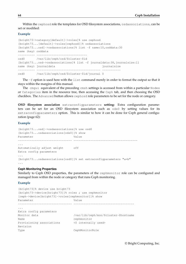
64 Ceph Installation
Within the cephosd role the templates for OSD filesystem associations, osdassociations, can beset or modified:
Example
[bright73->category[default]->roles]% use cephosd
[bright73...[default]->roles[cephosd]]% osdassociations
[bright73...osd]->osdassociations]% list -f name:10,osddata:30
name (key) osddata
---------- ------------------------------
osd0 /var/lib/ceph/osd/$cluster-$id
[bright73...osd->osdassociations]% list -f journaldata:38,journalsize:11
name (key) journaldata journalsize
---------- -------------------------------------- -----------
osd0 /var/lib/ceph/osd/$cluster-$id/journal 0
The -f option is used here with the list command merely in order to format the output so that itstays within the margins of this manual.
The cmgui equivalent of the preceding cmsh settings is accessed from within a particular Nodesor Categories item in the resource tree, then accessing the Ceph tab, and then choosing the OSDcheckbox. The Advanced button allows cephosd role parameters to be set for the node or category.
OSD filesystem association extraconfigparameters setting: Extra configuration parame-ters can be set for an OSD filesystem association such as ods0 by setting values for itsextraconfigparameters option. This is similar to how it can be done for Ceph general configu-ration (page 62):
Example
[bright73...osd]->osdassociations]% use osd0
[bright73...osdassociations[ods0]]% show
Parameter Value
-------------------------------- --------------------------------------
...
Automatically adjust weight off
Extra config parameters
...
[bright73...osdassociations[osd0]]% set extraconfigparameters "a=b"
...
Ceph Monitoring PropertiesSimilarly to Ceph OSD properties, the parameters of the cephmonitor role can be configured andmanaged from within the node or category that runs Ceph monitoring.
Example
[bright73]% device use bright73
[bright73->device[bright73]]% roles ; use cephmonitor
[ceph->device[bright73]->roles[cephmonitor]]% show
Parameter Value
-------------------------------- ------------------------------------
...
Extra config parameters
Monitor data /var/lib/ceph/mon/$cluster-$hostname
Name cephmonitor
Provisioning associations <0 internally used>
Revision
Type CephMonitorRole
© Bright Computing, Inc.
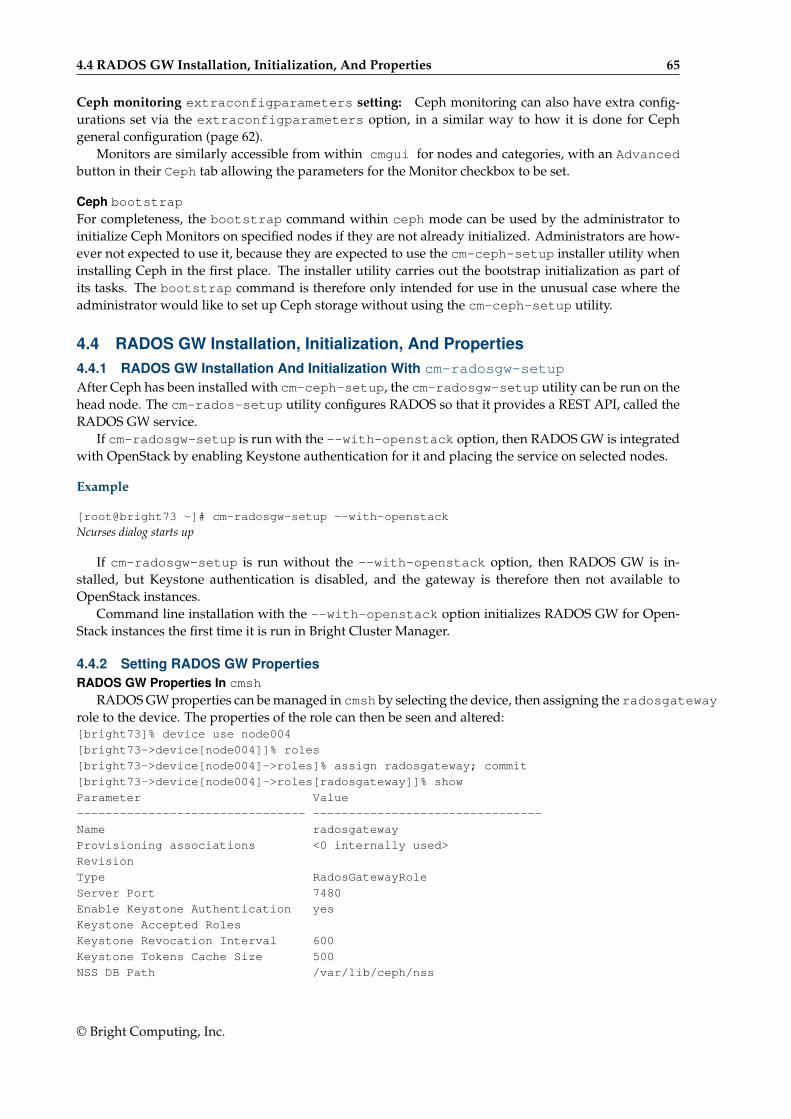
4.4 RADOS GW Installation, Initialization, And Properties 65
Ceph monitoring extraconfigparameters setting: Ceph monitoring can also have extra config-urations set via the extraconfigparameters option, in a similar way to how it is done for Cephgeneral configuration (page 62).
Monitors are similarly accessible from within cmgui for nodes and categories, with an Advancedbutton in their Ceph tab allowing the parameters for the Monitor checkbox to be set.
Ceph bootstrap
For completeness, the bootstrap command within ceph mode can be used by the administrator toinitialize Ceph Monitors on specified nodes if they are not already initialized. Administrators are how-ever not expected to use it, because they are expected to use the cm-ceph-setup installer utility wheninstalling Ceph in the first place. The installer utility carries out the bootstrap initialization as part ofits tasks. The bootstrap command is therefore only intended for use in the unusual case where theadministrator would like to set up Ceph storage without using the cm-ceph-setup utility.
4.4 RADOS GW Installation, Initialization, And Properties4.4.1 RADOS GW Installation And Initialization With cm-radosgw-setupAfter Ceph has been installed with cm-ceph-setup, the cm-radosgw-setup utility can be run on thehead node. The cm-rados-setup utility configures RADOS so that it provides a REST API, called theRADOS GW service.
If cm-radosgw-setup is run with the --with-openstack option, then RADOS GW is integratedwith OpenStack by enabling Keystone authentication for it and placing the service on selected nodes.
Example
[root@bright73 ~]# cm-radosgw-setup --with-openstack
Ncurses dialog starts up
If cm-radosgw-setup is run without the --with-openstack option, then RADOS GW is in-stalled, but Keystone authentication is disabled, and the gateway is therefore then not available toOpenStack instances.
Command line installation with the --with-openstack option initializes RADOS GW for Open-Stack instances the first time it is run in Bright Cluster Manager.
4.4.2 Setting RADOS GW PropertiesRADOS GW Properties In cmsh
RADOS GW properties can be managed in cmsh by selecting the device, then assigning the radosgatewayrole to the device. The properties of the role can then be seen and altered:[bright73]% device use node004
[bright73->device[node004]]% roles
[bright73->device[node004]->roles]% assign radosgateway; commit
[bright73->device[node004]->roles[radosgateway]]% show
Parameter Value
-------------------------------- --------------------------------
Name radosgateway
Provisioning associations <0 internally used>
Revision
Type RadosGatewayRole
Server Port 7480
Enable Keystone Authentication yes
Keystone Accepted Roles
Keystone Revocation Interval 600
Keystone Tokens Cache Size 500
NSS DB Path /var/lib/ceph/nss
© Bright Computing, Inc.
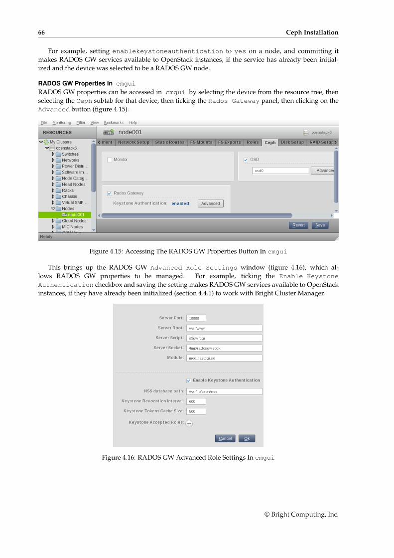
66 Ceph Installation
For example, setting enablekeystoneauthentication to yes on a node, and committing itmakes RADOS GW services available to OpenStack instances, if the service has already been initial-ized and the device was selected to be a RADOS GW node.
RADOS GW Properties In cmgui
RADOS GW properties can be accessed in cmgui by selecting the device from the resource tree, thenselecting the Ceph subtab for that device, then ticking the Rados Gateway panel, then clicking on theAdvanced button (figure 4.15).
Figure 4.15: Accessing The RADOS GW Properties Button In cmgui
This brings up the RADOS GW Advanced Role Settings window (figure 4.16), which al-lows RADOS GW properties to be managed. For example, ticking the Enable KeystoneAuthentication checkbox and saving the setting makes RADOS GW services available to OpenStackinstances, if they have already been initialized (section 4.4.1) to work with Bright Cluster Manager.
Figure 4.16: RADOS GW Advanced Role Settings In cmgui
© Bright Computing, Inc.
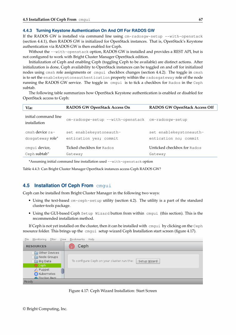
4.5 Installation Of Ceph From cmgui 67
4.4.3 Turning Keystone Authentication On And Off For RADOS GWIf the RADOS GW is installed via command line using cm-radosgw-setup --with-openstack(section 4.4.1), then RADOS GW is initialized for OpenStack instances. That is, OpenStack’s Keystoneauthentication via RADOS GW is then enabled for Ceph.
Without the --with-openstack option, RADOS GW is installed and provides a REST API, but isnot configured to work with Bright Cluster Manager OpenStack edition.
Initialization of Ceph and enabling Ceph (toggling Ceph to be available) are distinct actions. Afterinitialization is done, Ceph availability to OpenStack instances can be toggled on and off for initializednodes using cmsh role assignments or cmgui checkbox changes (section 4.4.2). The toggle in cmshis to set the enablekeystoneauthentication property within the radosgateway role of the noderunning the RADOS GW service. The toggle in cmgui is to tick a checkbox for Rados in the Cephsubtab.
The following table summarizes how OpenStack Keystone authentication is enabled or disabled forOpenStack access to Ceph:
Via: RADOS GW OpenStack Access On RADOS GW OpenStack Access Off
initial command linecm-radosgw-setup --with-openstack cm-radosgw-setup
installation
cmsh device ra- set enablekeystoneauth- set enablekeystoneauth-
dosgateway role∗ entication yes; commit entication no; commit
cmgui device, Ticked checkbox for Rados Unticked checkbox for Rados
Ceph subtab∗ Gateway Gateway
*Assuming initial command line installation used --with-openstack option
Table 4.4.3: Can Bright Cluster Manager OpenStack instances access Ceph RADOS GW?
4.5 Installation Of Ceph From cmgui
Ceph can be installed from Bright Cluster Manager in the following two ways:
• Using the text-based cm-ceph-setup utility (section 4.2). The utility is a part of the standardcluster-tools package.
• Using the GUI-based Ceph Setup Wizard button from within cmgui (this section). This is therecommended installation method.
If Ceph is not yet installed on the cluster, then it can be installed with cmgui by clicking on the Cephresource folder. This brings up the cmgui setup wizard Ceph Installation start screen (figure 4.17).
Figure 4.17: Ceph Wizard Installation: Start Screen
© Bright Computing, Inc.
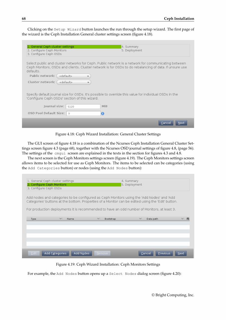
68 Ceph Installation
Clicking on the Setup Wizard button launches the run through the setup wizard. The first page ofthe wizard is the Ceph Installation General cluster settings screen (figure 4.18).
Figure 4.18: Ceph Wizard Installation: General Cluster Settings
The GUI screen of figure 4.18 is a combination of the Ncurses Ceph Installation General Cluster Set-tings screen figure 4.3 (page 68), together with the Ncurses OSD journal settings of figure 4.8, (page 56).The settings of the cmgui screen are explained in the texts in the section for figures 4.3 and 4.8.
The next screen is the Ceph Monitors settings screen (figure 4.19). The Ceph Monitors settings screenallows items to be selected for use as Ceph Monitors. The items to be selected can be categories (usingthe Add Categories button) or nodes (using the Add Nodes button):
Figure 4.19: Ceph Wizard Installation: Ceph Monitors Settings
For example, the Add Nodes button opens up a Select Nodes dialog screen (figure 4.20):
© Bright Computing, Inc.
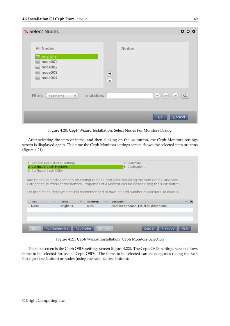
4.5 Installation Of Ceph From cmgui 69
Figure 4.20: Ceph Wizard Installation: Select Nodes For Monitors Dialog
After selecting the item or items, and then clicking on the OK button, the Ceph Monitors settingsscreen is displayed again. This time the Ceph Monitors settings screen shows the selected item or items(figure 4.21):
Figure 4.21: Ceph Wizard Installation: Ceph Monitors Selection
The next screen is the Ceph OSDs settings screen (figure 4.22). The Ceph OSDs settings screen allowsitems to be selected for use as Ceph OSDs. The items to be selected can be categories (using the AddCategories button) or nodes (using the Add Nodes button):
© Bright Computing, Inc.
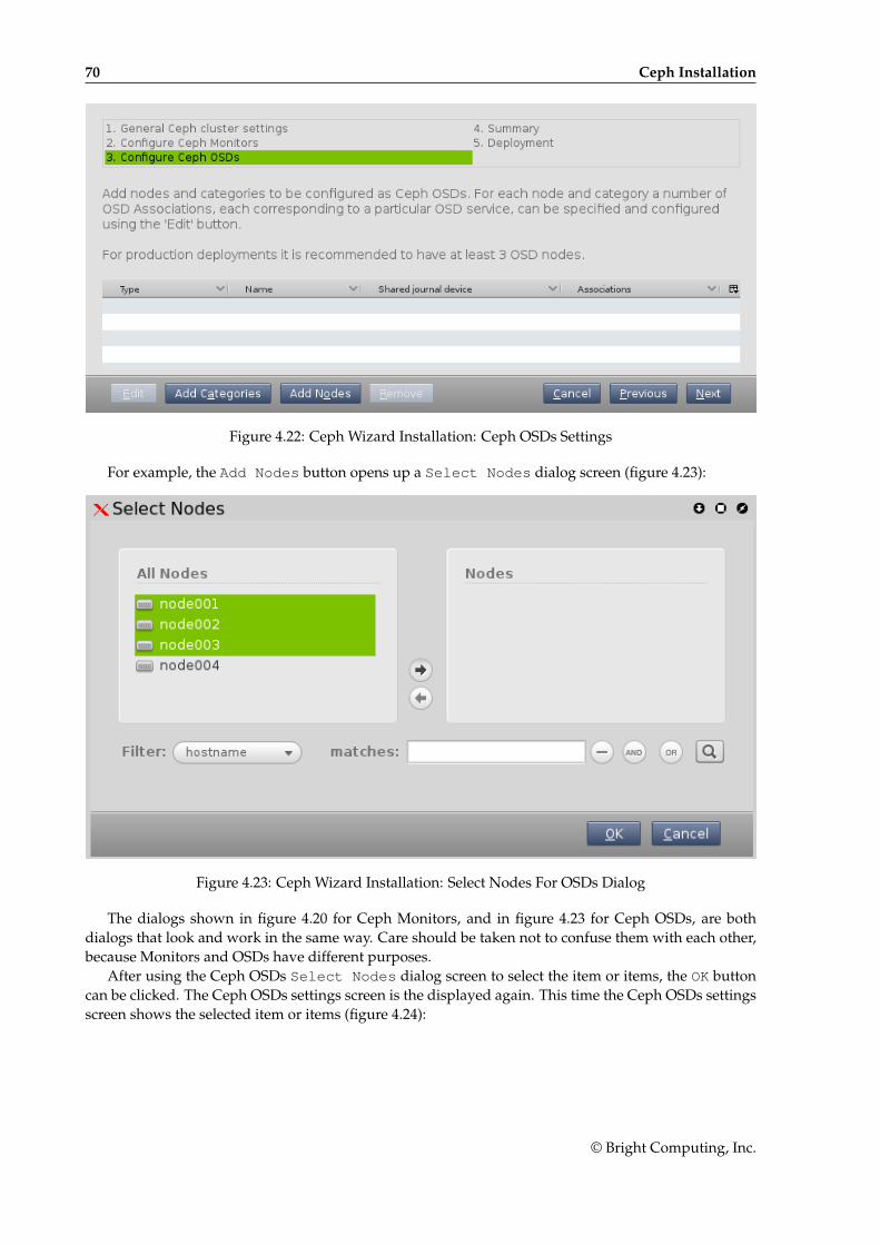
70 Ceph Installation
Figure 4.22: Ceph Wizard Installation: Ceph OSDs Settings
For example, the Add Nodes button opens up a Select Nodes dialog screen (figure 4.23):
Figure 4.23: Ceph Wizard Installation: Select Nodes For OSDs Dialog
The dialogs shown in figure 4.20 for Ceph Monitors, and in figure 4.23 for Ceph OSDs, are bothdialogs that look and work in the same way. Care should be taken not to confuse them with each other,because Monitors and OSDs have different purposes.
After using the Ceph OSDs Select Nodes dialog screen to select the item or items, the OK buttoncan be clicked. The Ceph OSDs settings screen is the displayed again. This time the Ceph OSDs settingsscreen shows the selected item or items (figure 4.24):
© Bright Computing, Inc.
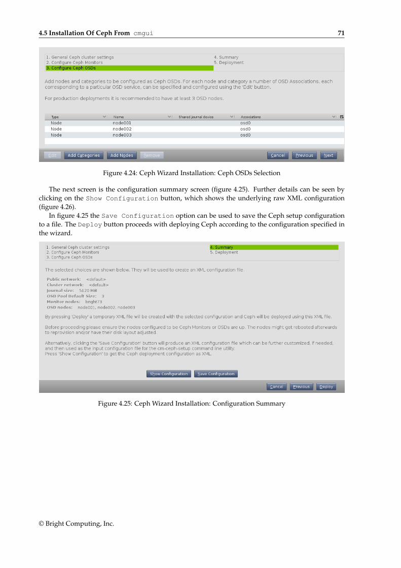
4.5 Installation Of Ceph From cmgui 71
Figure 4.24: Ceph Wizard Installation: Ceph OSDs Selection
The next screen is the configuration summary screen (figure 4.25). Further details can be seen byclicking on the Show Configuration button, which shows the underlying raw XML configuration(figure 4.26).
In figure 4.25 the Save Configuration option can be used to save the Ceph setup configurationto a file. The Deploy button proceeds with deploying Ceph according to the configuration specified inthe wizard.
Figure 4.25: Ceph Wizard Installation: Configuration Summary
© Bright Computing, Inc.
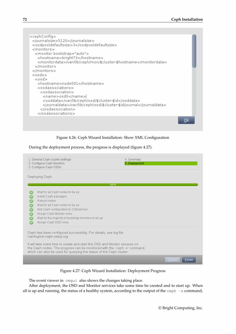
72 Ceph Installation
Figure 4.26: Ceph Wizard Installation: Show XML Configuration
During the deployment process, the progress is displayed (figure 4.27).
Figure 4.27: Ceph Wizard Installation: Deployment Progress
The event viewer in cmgui also shows the changes taking place.After deployment, the OSD and Monitor services take some time be created and to start up. When
all is up and running, the status of a healthy system, according to the output of the ceph -s command,
© Bright Computing, Inc.
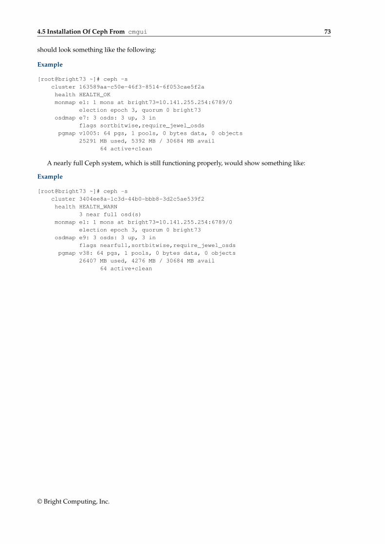
4.5 Installation Of Ceph From cmgui 73
should look something like the following:
Example
[root@bright73 ~]# ceph -s
cluster 163589aa-c50e-46f3-8514-6f053cae5f2a
health HEALTH_OK
monmap e1: 1 mons at bright73=10.141.255.254:6789/0
election epoch 3, quorum 0 bright73
osdmap e7: 3 osds: 3 up, 3 in
flags sortbitwise,require_jewel_osds
pgmap v1005: 64 pgs, 1 pools, 0 bytes data, 0 objects
25291 MB used, 5392 MB / 30684 MB avail
64 active+clean
A nearly full Ceph system, which is still functioning properly, would show something like:
Example
[root@bright73 ~]# ceph -s
cluster 3404ee8a-1c3d-44b0-bbb8-3d2c5ae539f2
health HEALTH_WARN
3 near full osd(s)
monmap e1: 1 mons at bright73=10.141.255.254:6789/0
election epoch 3, quorum 0 bright73
osdmap e9: 3 osds: 3 up, 3 in
flags nearfull,sortbitwise,require_jewel_osds
pgmap v38: 64 pgs, 1 pools, 0 bytes data, 0 objects
26407 MB used, 4276 MB / 30684 MB avail
64 active+clean
© Bright Computing, Inc.

5User Management And Getting
OpenStack Instances UpIn this chapter:
• Section 5.1 describes Bright Cluster Manager’s user management integration with OpenStack.
• Section 5.2 describes how a user instance can be run with OpenStack under Bright Cluster Man-ager. A user instance is an instance that is not a tightly-integrated Bright-managed instance. ABright-managed instance is a special case of an user instance. Bright-managed nodes are treatedby Bright Cluster Manager very much like a regular nodes.
• Section 5.3 describes how a Bright-managed instance is managed in Bright Cluster Manager
5.1 Bright Cluster Manager Integration Of User Management In OpenStackUser management in Bright Cluster Manager without OpenStack is covered in Chapter 6 of the Admin-istrator Manual. Users managed in this way are called Bright users.
OpenStack allows a separate set of users to be created within its projects. By default, these OpenStackusers are set up to be independent of the Bright users.
OpenStack user accounts are of two kinds:
• regular users: these are end users who get to use an OpenStack user instance or a Bright-managedOpenStack instance. These can be managed by Bright Cluster Manager’s LDAP, or can also simplybe managed within OpenStack, depending on the Keystone backend driver used.
• service users: these user accounts are used to run the OpenStack service components. They areassociated with the service project and admin role. Thus, the Nova service has a nova user, theCinder service has a cinder user, and so on, and these are all assigned an admin role. The list ofservice user names can be listed in the default installation as follows:
[bright73->openstack[default]->roleassignments]% list -f name:25 | grep service
admin:service:admin
cinder:service:admin
cmdaemon:service:admin
glance:service:admin
heat:service:admin
keystone:service:admin
neutron:service:admin
nova:service:admin
radosgw:service:admin
© Bright Computing, Inc.
76 User Management And Getting OpenStack Instances Up
The OpenStack service users are stored in the Keystone database, managed by the OpenStackMariaDB running on the controller nodes.
In cmsh the role assignment name field is in the form of:
<OpenStack user name>:<project>:<role>
The background note on page 81 has some further details on role assignment in Bright ClusterManager OpenStack edition.
The service user radosgw is created only if the RADOS GW is installed (section 4.4).
Regular OpenStack users can be created in several ways, including:
• using cmsh, from within openstack mode
• using cmgui, from within the OpenStack tab
• using the OpenStack Horizon dashboard, where clicking on the Identity sidebar resource leadsto the Users management window
• using the openstack command line utility that comes with OpenStack.
• using the Keystone Python API, which is an option that is more likely to be of interest to developersrather than system administrators
The details of how this is carried out depends on user database backend configuration. OpenStackusers and Bright users can be given the same name and password in several ways, depending on thedatabase driver used by Keystone (section 3.1.4), and how the administrator configures the users usingthe initialization and migration scripts (section 5.1.2).
Having the OpenStack service users not be in the Bright Cluster Manager LDAP and thus not be thesame as Bright users has some advantages.
Having OpenStack regular users be the same as Bright users is also something that administratorsmay want.
Background Note: The User Database Drivers, User Migration And InitializationThis section on database drivers is offered as background material to provide a deeper understandingof user management in Bright Cluster Manager with OpenStack. It can be skipped by administratorswho have no need to understand how the configuration can be customized, or who have been providedwith a customized configuration already.
It should be understood that Bright users are not OpenStack users by default when OpenStack setupis carried out. To make a Bright user able to use OpenStack under the same user name, some configu-ration must be carried out. The exact configuration depends upon the use case. The main configurationinvolves the type of backend user database driver used, and can additionally include the option of ini-tialization and migration scripts.
Initialization and migration scripts are scripts that can be used to initialize and migrate Bright usersto become OpenStack users, after OpenStack setup has been carried out.
In this background note, two kinds of Bright users are defined:
1. legacy users: These are Bright users created from before the OpenStack initialization and migra-tion scripts are working.
2. fresh users: These are Bright users created after the OpenStack initialization and migration scriptsare working.
The following table displays the driver configuration options that allow the Bright Cluster Manageruser to use OpenStack.
© Bright Computing, Inc.
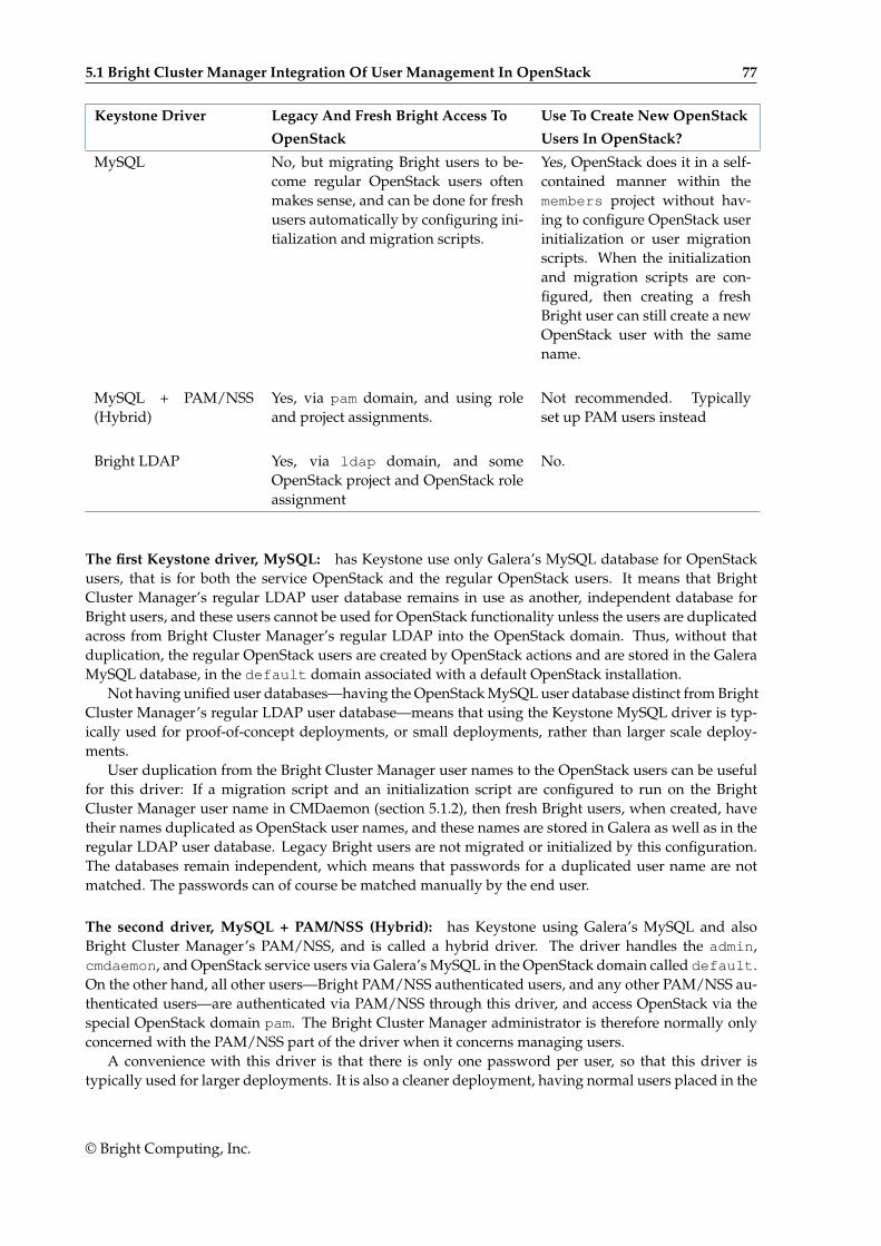
5.1 Bright Cluster Manager Integration Of User Management In OpenStack 77
Keystone Driver Legacy And Fresh Bright Access To Use To Create New OpenStack
OpenStack Users In OpenStack?
MySQL No, but migrating Bright users to be-come regular OpenStack users oftenmakes sense, and can be done for freshusers automatically by configuring ini-tialization and migration scripts.
Yes, OpenStack does it in a self-contained manner within themembers project without hav-ing to configure OpenStack userinitialization or user migrationscripts. When the initializationand migration scripts are con-figured, then creating a freshBright user can still create a newOpenStack user with the samename.
MySQL + PAM/NSS(Hybrid)
Yes, via pam domain, and using roleand project assignments.
Not recommended. Typicallyset up PAM users instead
Bright LDAP Yes, via ldap domain, and someOpenStack project and OpenStack roleassignment
No.
The first Keystone driver, MySQL: has Keystone use only Galera’s MySQL database for OpenStackusers, that is for both the service OpenStack and the regular OpenStack users. It means that BrightCluster Manager’s regular LDAP user database remains in use as another, independent database forBright users, and these users cannot be used for OpenStack functionality unless the users are duplicatedacross from Bright Cluster Manager’s regular LDAP into the OpenStack domain. Thus, without thatduplication, the regular OpenStack users are created by OpenStack actions and are stored in the GaleraMySQL database, in the default domain associated with a default OpenStack installation.
Not having unified user databases—having the OpenStack MySQL user database distinct from BrightCluster Manager’s regular LDAP user database—means that using the Keystone MySQL driver is typ-ically used for proof-of-concept deployments, or small deployments, rather than larger scale deploy-ments.
User duplication from the Bright Cluster Manager user names to the OpenStack users can be usefulfor this driver: If a migration script and an initialization script are configured to run on the BrightCluster Manager user name in CMDaemon (section 5.1.2), then fresh Bright users, when created, havetheir names duplicated as OpenStack user names, and these names are stored in Galera as well as in theregular LDAP user database. Legacy Bright users are not migrated or initialized by this configuration.The databases remain independent, which means that passwords for a duplicated user name are notmatched. The passwords can of course be matched manually by the end user.
The second driver, MySQL + PAM/NSS (Hybrid): has Keystone using Galera’s MySQL and alsoBright Cluster Manager’s PAM/NSS, and is called a hybrid driver. The driver handles the admin,cmdaemon, and OpenStack service users via Galera’s MySQL in the OpenStack domain called default.On the other hand, all other users—Bright PAM/NSS authenticated users, and any other PAM/NSS au-thenticated users—are authenticated via PAM/NSS through this driver, and access OpenStack via thespecial OpenStack domain pam. The Bright Cluster Manager administrator is therefore normally onlyconcerned with the PAM/NSS part of the driver when it concerns managing users.
A convenience with this driver is that there is only one password per user, so that this driver istypically used for larger deployments. It is also a cleaner deployment, having normal users placed in the
© Bright Computing, Inc.
78 User Management And Getting OpenStack Instances Up
pam domain and handling them there. Also, if using Bright Cluster Manager for user management, thenthe administrator can manage passwords and other properties in the standard Bright Cluster Managerway from the top-level cmsh user mode.
With this driver, Bright users that are authenticated with LDAP, can be authenticated by Keystonevia PAM/NSS. The driver assigns the user the OpenStack pam domain. Within the OpenStack pamdomain, an assignment must be carried out by the administrator for the OpenStack role and for theOpenStack project. Without these role and project assignments within the pam domain, the users aremerely authenticated, but disallowed the use of OpenStack services. Typically, therefore, to manage thePAM users in the pam domain of OpenStack, an administrative user, for example, pamadmin, can becreated within the pam domain, and given the OpenStack admin role. Such a pamadmin administratoris a separate user from the admin created by default in the default domain. This pamadmin can thenassign an appropriate OpenStack role and OpenStack project to the user in the pam domain.
User duplication from the Bright user names to the OpenStack users, using a migration script andan initialization script, is typically not useful for this driver, since it works against the clean placementdescribed earlier. If a migration script and an initialization script are configured to run on the Bright username in CMDaemon (section 5.1.2), then fresh Bright users, when created, have their names duplicatedas OpenStack user names, and these names are stored in Galera together with the service OpenStackusers, as well as in the regular LDAP user database. Legacy Bright users are not migrated or initializedby this configuration. The databases remain independent, which means that passwords for a duplicateduser name are not matched. The passwords can of course be matched manually by the end user.
The third driver, Bright LDAP: has Keystone using Bright Cluster Manager’s own LDAP database,and does not use the OpenStack user database for regular users. That is, Keystone, when using thisdriver, handles Bright LDAP users only, ignores any NSS/PAM users, and ignores any regular Open-Stack users in Galera. The admin, cmdaemon, and service OpenStack users, on the other hand, are stillused by Keystone from Galera in OpenStack.
Creation of a fresh user via OpenStack actions will fail, because the LDAPS access from OpenStack isread-only. There is no account ldapadmin that can be created analogous to pamadmin that has the sameabilities that pamadmin had with the second driver. That is, there is no account ldapadmin to assignprojects and roles to LDAP users. Current LDAP users can be created via a CMDaemon front-end, suchas the top-level user mode of cmsh in Bright, and are automatically go to the domain associated withOpenStack called ldap. OpenStack projects and OpenStack roles can be assigned to a user from theOpenStack command line. The convenience of a single password for users, the simple architecture, andhaving everything is contained within Bright Cluster Manager, means that this driver is typically usefulfor small or medium organizations that are using Bright Cluster Manager as is, without authenticatingit to an external database via PAM/NSS.
An aside on duplication when using this driver: Duplication is mentioned here for completeness. Itis available, but typically pointless for this driver. If a migration script and an initialization script areconfigured to run on the Bright user name in CMDaemon (section 5.1.2), then a fresh LDAP user nameis duplicated during creation, as an OpenStack user name, and also stored in Galera, but not used fromGalera. The databases remain independent, which means that passwords for a duplicated user nameare not matched. The passwords can of course be matched manually by the end user. Legacy users arenot migrated or initialized by this configuration.
Normally one of the three driver types is chosen in the user management screen during the wizardinstallation (section 3.1.4) or Ncurses installation (section 3.2.4).
However, the driver type can be added or removed after OpenStack installation, within cmsh byusing the authbackends submode. For example, adding a name to the chosen driver type adds thedriver while assigning it a name in CMDaemon:
Example
© Bright Computing, Inc.
5.1 Bright Cluster Manager Integration Of User Management In OpenStack 79
[bright73->openstack[default]->settings->authentication->authbackends]% add<TAB><TAB>hybrid ldap sql
[bright73->...authbackends]]% add sql sql |#choosing sql as name for type sql backend
Further configuration to suit needs can be quite involved. It is therefore recommended to select theappropriate driver during a wizard or Ncurses installation to begin with.
5.1.1 Managing OpenStack Users As Bright Cluster Manager UsersMost administrators should find that the most convenient way to set up Bright Cluster Manager andOpenStack users is using cmsh. For Bright Cluster Manager users this is done from the main usermode, while for OpenStack users, it is done from within the users submodes, under OpenStack mode,in the cmsh hierarchy.
Background Note: Avoiding Confusion About User(s) And (Sub)ModesThe administrator should understand that there is a difference between:
• OpenStack->users submode: OpenStack users are managed from this submode
• OpenStack->settings->users submode: the settings for OpenStack users are managed fromthis submode
• Bright Cluster Manager user mode: Bright Cluster Manager users are managed from this mode
The following treeview illustrates these user(s) (sub)modes in the cmsh hierarchy:
[cmsh]
|-- ...
|-- openstack
| |-- ...
| |-- settings
| | |--...
| | ‘-- users
| |-- ...
| ‘-- users
|-- ...
‘-- user
5.1.2 Synchronizing Users With The OpenStack Initialization And Migration ScriptsSetting the initialization and migration scripts: Bright Cluster Manager provides initialization andmigration scripts that can be called after creating a Bright user. When applied to a Bright Cluster Man-ager user, the OpenStack user of the same name is created as follows:
• The migration script, /cm/local/apps/cluster-tools/bin/cm-user-migration, copiesa Bright Cluster Manager user name from the LDAP records over to the OpenStack Keystonerecords, and by default sets a random password for the OpenStack user.
• The initialization script, /cm/local/apps/cluster-tools/bin/cm-user-init, creates anOpenStack project for the OpenStack user with the same name, if it does not already exist. Theuser is also assigned the member role. Role assignment here means that the OpenStack user isassociated with a project and assigned a role for the purposes of the OpenStack utility (page 81,Background Note: Automated Role Assignment In OpenStack).
The cmsh parameters userinitscript and migrationscript can be set to these initializationand migration script paths. The parameters are initially blank by default. They can be set from withinthe OpenStack settings submode of cmsh for users as follows:
© Bright Computing, Inc.
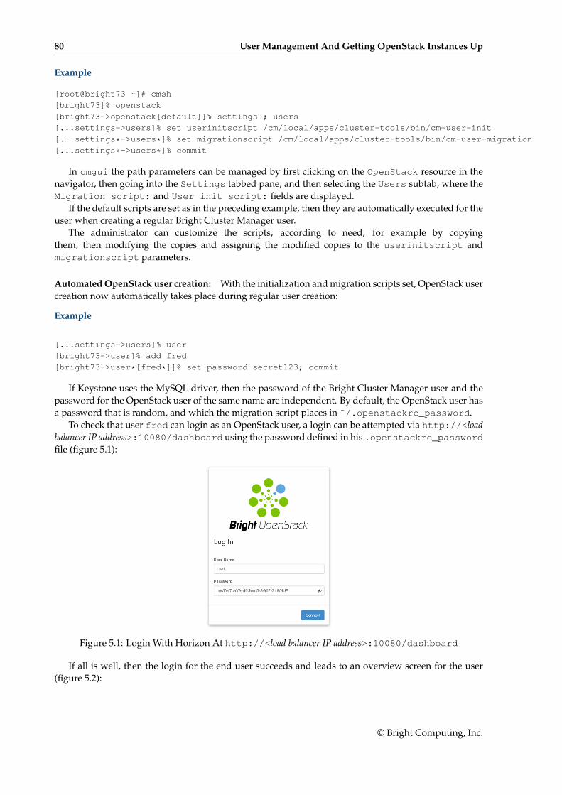
80 User Management And Getting OpenStack Instances Up
Example
[root@bright73 ~]# cmsh
[bright73]% openstack
[bright73->openstack[default]]% settings ; users
[...settings->users]% set userinitscript /cm/local/apps/cluster-tools/bin/cm-user-init
[...settings*->users*]% set migrationscript /cm/local/apps/cluster-tools/bin/cm-user-migration
[...settings*->users*]% commit
In cmgui the path parameters can be managed by first clicking on the OpenStack resource in thenavigator, then going into the Settings tabbed pane, and then selecting the Users subtab, where theMigration script: and User init script: fields are displayed.
If the default scripts are set as in the preceding example, then they are automatically executed for theuser when creating a regular Bright Cluster Manager user.
The administrator can customize the scripts, according to need, for example by copyingthem, then modifying the copies and assigning the modified copies to the userinitscript andmigrationscript parameters.
Automated OpenStack user creation: With the initialization and migration scripts set, OpenStack usercreation now automatically takes place during regular user creation:
Example
[...settings->users]% user
[bright73->user]% add fred
[bright73->user*[fred*]]% set password secret123; commit
If Keystone uses the MySQL driver, then the password of the Bright Cluster Manager user and thepassword for the OpenStack user of the same name are independent. By default, the OpenStack user hasa password that is random, and which the migration script places in ˜/.openstackrc_password.
To check that user fred can login as an OpenStack user, a login can be attempted via http://<loadbalancer IP address>:10080/dashboard using the password defined in his .openstackrc_passwordfile (figure 5.1):
Figure 5.1: Login With Horizon At http://<load balancer IP address>:10080/dashboard
If all is well, then the login for the end user succeeds and leads to an overview screen for the user(figure 5.2):
© Bright Computing, Inc.
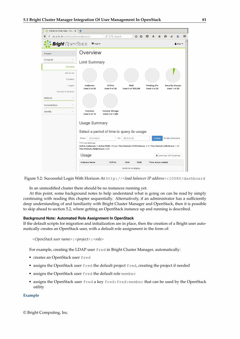
5.1 Bright Cluster Manager Integration Of User Management In OpenStack 81
Figure 5.2: Successful Login With Horizon At http://<load balancer IP address>:10080/dashboard
In an unmodified cluster there should be no instances running yet.At this point, some background notes to help understand what is going on can be read by simply
continuing with reading this chapter sequentially. Alternatively, if an administrator has a sufficientlydeep understanding of and familiarity with Bright Cluster Manager and OpenStack, then it is possibleto skip ahead to section 5.2, where getting an OpenStack instance up and running is described.
Background Note: Automated Role Assignment In OpenStackIf the default scripts for migration and initialization are in place, then the creation of a Bright user auto-matically creates an OpenStack user, with a default role assignment in the form of:
<OpenStack user name>:<project>:<role>
For example, creating the LDAP user fred in Bright Cluster Manager, automatically:
• creates an OpenStack user fred
• assigns the OpenStack user fred the default project fred, creating the project if needed
• assigns the OpenStack user fred the default role member
• assigns the OpenStack user fred a key fred:fred:member that can be used by the OpenStackutility
Example
© Bright Computing, Inc.
82 User Management And Getting OpenStack Instances Up
[bright73->user[fred]]% openstack users
[bright73->openstack[default]->users]% list -f name
name (key)
--------------------
admin
cinder
cmdaemon
fred
glance
heat
keystone
neutron
nova
[bright73->openstack[default]->users]% projects
[bright73->openstack[default]->projects]% list
Name (key) UUID (key) Domain Enabled MOTD
------------ --------------------------------- ------------------ ------- ------
bright 83b48ea2016c4658b3b1e01a910011d9 Default (default) yes
fred b48cd2f6da4645a8886b494ad5f459c6 Default (default) yes
service aa239b1f054a470cbe40f74984a9331d Default (default) yes
[bright73->openstack[default]->projects]% roleassignments; list -f name,user,project,role
name (key) user project role
-------------------- -------------------- -------------------- --------------------
admin:bright:admin admin (bfd7fd66b1ab+ bright (83b48ea2016+ admin (c7b7e8f8c885+
admin:service:admin admin (bfd7fd66b1ab+ service (aa239b1f05+ admin (c7b7e8f8c885+
cinder:service:admin cinder (e173c5545c8+ service (aa239b1f05+ admin (c7b7e8f8c885+
cmdaemon:bright:adm+ cmdaemon (fae4250c3+ bright (83b48ea2016+ admin (c7b7e8f8c885+
cmdaemon:service:ad+ cmdaemon (fae4250c3+ service (aa239b1f05+ admin (c7b7e8f8c885+
fred:fred:member fred (80e16841e3df2+ fred (b48cd2f6da464+ member (6cb5e5359b6+
glance:service:admin glance (2a0d739783d+ service (aa239b1f05+ admin (c7b7e8f8c885+
heat:service:admin heat (7acdc31888534+ service (aa239b1f05+ admin (c7b7e8f8c885+
keystone:service:ad+ keystone (1048db4a5+ service (aa239b1f05+ admin (c7b7e8f8c885+
neutron:service:adm+ neutron (e1b01d92e9+ service (aa239b1f05+ admin (c7b7e8f8c885+
nova:service:admin nova (634f35b3ee0e4+ service (aa239b1f05+ admin (c7b7e8f8c885+
[bright73->openstack[default]->roleassignments]%
Background Note: Automated Writing Out Of The .openstackrc* FilesOpenStack users have a .openstackrc file and a .openstackrc_password file associ-ated with them. The .openstackrc file provides the OpenStack environment, while the.openstackrc_password file provides the OpenStack password. This environment can be used byopenstack, the OpenStack utility that an OpenStack user can run to manage instances.
Within the settings submode of OpenStack there is a users submode. Within that users sub-mode the administrator can set the following parameters to configure the .openstackrc* files:
• Write out OpenStack RC for users: This parameter configures how the .openstackrcfile is written for an OpenStack user:
– matchinghomedirectories: writes the file only to home directories that match OpenStackuser names
– allhomedirectories: writes the file to all home directories. That is, even if no OpenStackuser matches that name
– off: does not write out a file
• Write out .openstackrc_password: This parameter can take yes or no as its value. Thevalue decides if the .openstackrc_password file is written for an OpenStack user. This feature
© Bright Computing, Inc.
5.1 Bright Cluster Manager Integration Of User Management In OpenStack 83
only operates when the user is created. So if this option is made active after user creation, then nopassword file is written out.
Example
[root@bright73 ~]# cmsh
[bright73]% openstack
[bright73->openstack[default]]% settings; users
[...settings->users]% set writeoutopenstackrcforusers matchinghomedirectories
[...settings->users*]% set writeout.openstackrc_password yes
[...settings->users*]% commit
With the preceding configuration for the .openstackrc* files, if an OpenStack user fred is createdas in the example on page 80, then the home directory for fred would look something like:
Example
[root@bright73 ~]# ls -a /home/fred/
. .. .bash_logout .bash_profile .bashrc .mozilla .openstackrc .openstackrc_password
The .openstackrc* file contents are similar to the following output:
Example
[root@bright73 ~]# cat /home/fred/.openstackrc_password
OS_PASSWORD="LMlr6oRENZoIp0iqaI4304JGNn632P"
[root@bright73 ~]# cat /home/fred/.openstackrc
# This section of this file was automatically generated by cmd. Do not edit manually!
# BEGIN AUTOGENERATED SECTION -- DO NOT REMOVE
# This file has been generated by the CMDaemon and is meant
# to be sourced from within the ~/.bashrc
export OS_TENANT_NAME=""
export OS_USERNAME="fred"
# Public Auth URL (used by users)
export OS_AUTH_URL="http://<load balancer IP address>:5000/v3"
# For keystone v3
export OS_PROJECT_DOMAIN_ID="default"
export OS_USER_DOMAIN_ID="default"
export OS_IDENTITY_API_VERSION=3 # for the ’openstack’ utility to work
export OS_CACERT="/etc/keystone/ssl/certs/ca.pem"
# END AUTOGENERATED SECTION -- DO NOT REMOVE
The value of <load balancer IP address> in the .openstackrc output is a dotted quad value or aresolvable host name, and is the address or name of the HAProxy load balancer that Bright ClusterManager uses for its OpenStack deployment. The load balancer address is normally the IP address ofthe head node on the external network on a smaller cluster.
Background Note: Changing The End User OpenStack PasswordThe end user is given a password for OpenStack user access by the initialization script. This password,stored in ˜/.openstackrc_password, is long, and somewhat random. Most users would thereforelike to change it to something that is easier for them to remember. This can be done in the dashboard by,for example, user fred, by clicking on the name fred in the top right hand corner, then selecting theSettings option, and then selecting the Change Password option.
The OpenStack APL CLI client openstack can be set to use the .openstackrcand .openstackrc_password files, which were initialized by the cm-user-init andcm-user-migration scripts earlier on (page 79). The end user can, if required, update the˜/.openstackrc_password file by hand after a password change is made by the dashboard.
© Bright Computing, Inc.
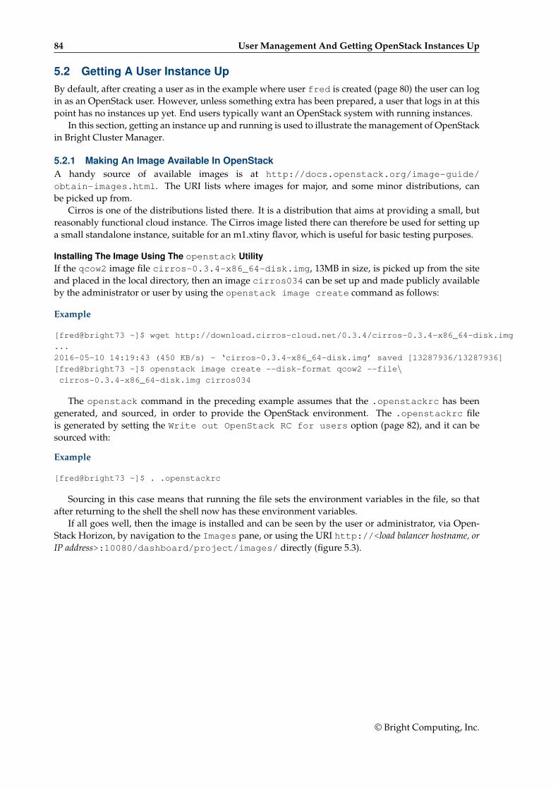
84 User Management And Getting OpenStack Instances Up
5.2 Getting A User Instance UpBy default, after creating a user as in the example where user fred is created (page 80) the user can login as an OpenStack user. However, unless something extra has been prepared, a user that logs in at thispoint has no instances up yet. End users typically want an OpenStack system with running instances.
In this section, getting an instance up and running is used to illustrate the management of OpenStackin Bright Cluster Manager.
5.2.1 Making An Image Available In OpenStackA handy source of available images is at http://docs.openstack.org/image-guide/obtain-images.html. The URI lists where images for major, and some minor distributions, canbe picked up from.
Cirros is one of the distributions listed there. It is a distribution that aims at providing a small, butreasonably functional cloud instance. The Cirros image listed there can therefore be used for setting upa small standalone instance, suitable for an m1.xtiny flavor, which is useful for basic testing purposes.
Installing The Image Using The openstack UtilityIf the qcow2 image file cirros-0.3.4-x86_64-disk.img, 13MB in size, is picked up from the siteand placed in the local directory, then an image cirros034 can be set up and made publicly availableby the administrator or user by using the openstack image create command as follows:
Example
[fred@bright73 ~]$ wget http://download.cirros-cloud.net/0.3.4/cirros-0.3.4-x86_64-disk.img
...
2016-05-10 14:19:43 (450 KB/s) - ‘cirros-0.3.4-x86_64-disk.img’ saved [13287936/13287936]
[fred@bright73 ~]$ openstack image create --disk-format qcow2 --file\cirros-0.3.4-x86_64-disk.img cirros034
The openstack command in the preceding example assumes that the .openstackrc has beengenerated, and sourced, in order to provide the OpenStack environment. The .openstackrc fileis generated by setting the Write out OpenStack RC for users option (page 82), and it can besourced with:
Example
[fred@bright73 ~]$ . .openstackrc
Sourcing in this case means that running the file sets the environment variables in the file, so thatafter returning to the shell the shell now has these environment variables.
If all goes well, then the image is installed and can be seen by the user or administrator, via Open-Stack Horizon, by navigation to the Images pane, or using the URI http://<load balancer hostname, orIP address>:10080/dashboard/project/images/ directly (figure 5.3).
© Bright Computing, Inc.
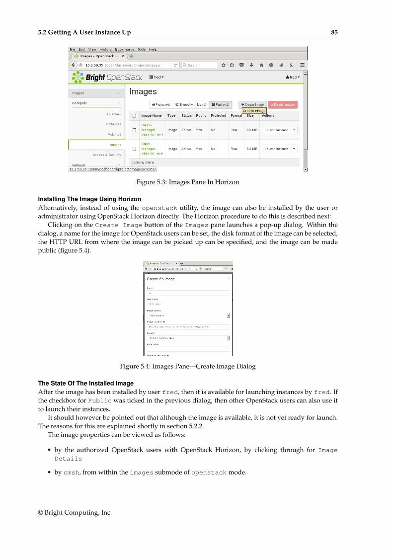
5.2 Getting A User Instance Up 85
Figure 5.3: Images Pane In Horizon
Installing The Image Using HorizonAlternatively, instead of using the openstack utility, the image can also be installed by the user oradministrator using OpenStack Horizon directly. The Horizon procedure to do this is described next:
Clicking on the Create Image button of the Images pane launches a pop-up dialog. Within thedialog, a name for the image for OpenStack users can be set, the disk format of the image can be selected,the HTTP URL from where the image can be picked up can be specified, and the image can be madepublic (figure 5.4).
Figure 5.4: Images Pane—Create Image Dialog
The State Of The Installed ImageAfter the image has been installed by user fred, then it is available for launching instances by fred. Ifthe checkbox for Public was ticked in the previous dialog, then other OpenStack users can also use itto launch their instances.
It should however be pointed out that although the image is available, it is not yet ready for launch.The reasons for this are explained shortly in section 5.2.2.
The image properties can be viewed as follows:
• by the authorized OpenStack users with OpenStack Horizon, by clicking through for ImageDetails
• by cmsh, from within the images submode of openstack mode.
© Bright Computing, Inc.
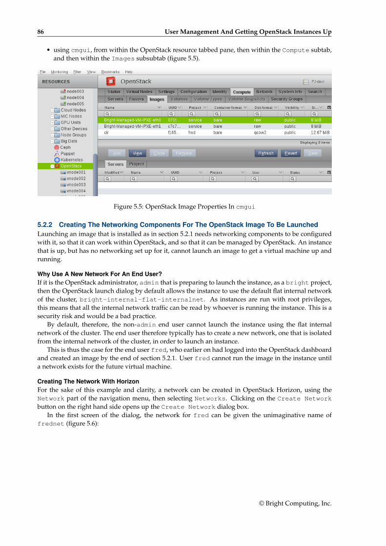
86 User Management And Getting OpenStack Instances Up
• using cmgui, from within the OpenStack resource tabbed pane, then within the Compute subtab,and then within the Images subsubtab (figure 5.5).
Figure 5.5: OpenStack Image Properties In cmgui
5.2.2 Creating The Networking Components For The OpenStack Image To Be LaunchedLaunching an image that is installed as in section 5.2.1 needs networking components to be configuredwith it, so that it can work within OpenStack, and so that it can be managed by OpenStack. An instancethat is up, but has no networking set up for it, cannot launch an image to get a virtual machine up andrunning.
Why Use A New Network For An End User?If it is the OpenStack administrator, admin that is preparing to launch the instance, as a bright project,then the OpenStack launch dialog by default allows the instance to use the default flat internal networkof the cluster, bright-internal-flat-internalnet. As instances are run with root privileges,this means that all the internal network traffic can be read by whoever is running the instance. This is asecurity risk and would be a bad practice.
By default, therefore, the non-admin end user cannot launch the instance using the flat internalnetwork of the cluster. The end user therefore typically has to create a new network, one that is isolatedfrom the internal network of the cluster, in order to launch an instance.
This is thus the case for the end user fred, who earlier on had logged into the OpenStack dashboardand created an image by the end of section 5.2.1. User fred cannot run the image in the instance untila network exists for the future virtual machine.
Creating The Network With HorizonFor the sake of this example and clarity, a network can be created in OpenStack Horizon, using theNetwork part of the navigation menu, then selecting Networks. Clicking on the Create Networkbutton on the right hand side opens up the Create Network dialog box.
In the first screen of the dialog, the network for fred can be given the unimaginative name offrednet (figure 5.6):
© Bright Computing, Inc.
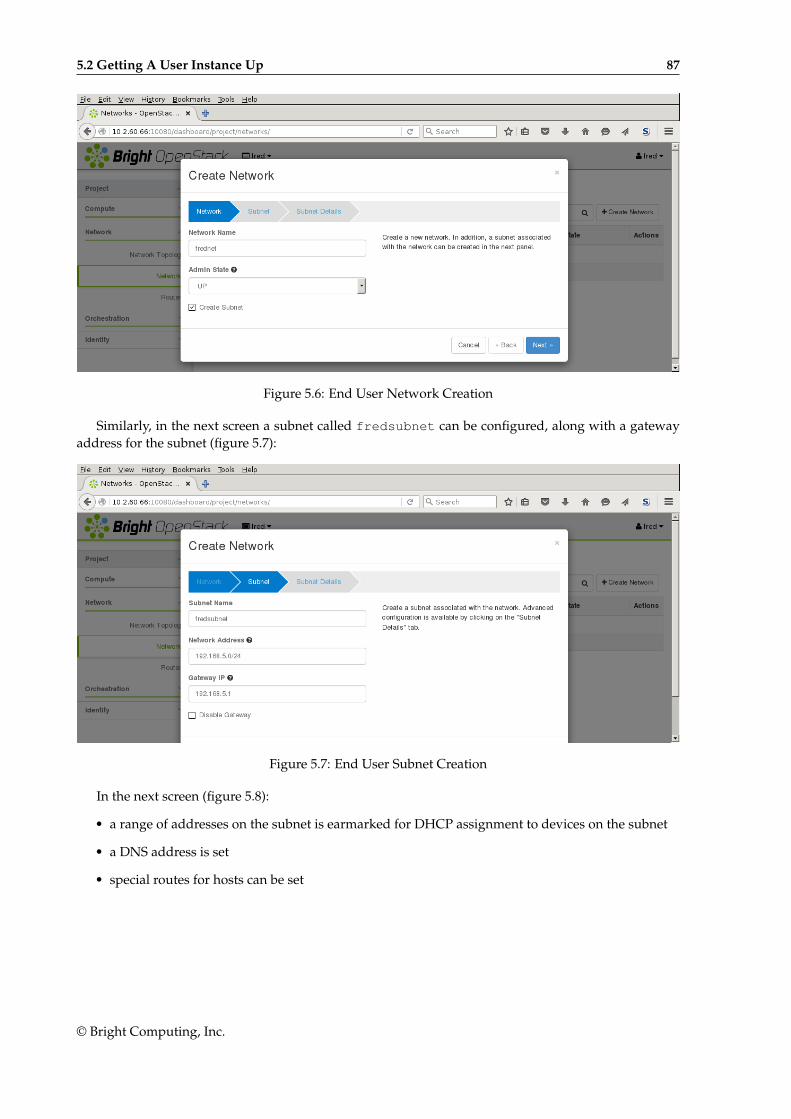
5.2 Getting A User Instance Up 87
Figure 5.6: End User Network Creation
Similarly, in the next screen a subnet called fredsubnet can be configured, along with a gatewayaddress for the subnet (figure 5.7):
Figure 5.7: End User Subnet Creation
In the next screen (figure 5.8):
• a range of addresses on the subnet is earmarked for DHCP assignment to devices on the subnet
• a DNS address is set
• special routes for hosts can be set
© Bright Computing, Inc.
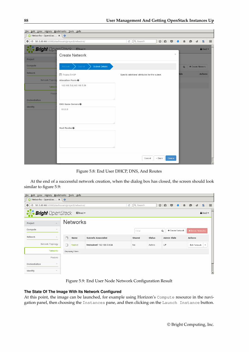
88 User Management And Getting OpenStack Instances Up
Figure 5.8: End User DHCP, DNS, And Routes
At the end of a successful network creation, when the dialog box has closed, the screen should looksimilar to figure 5.9:
Figure 5.9: End User Node Network Configuration Result
The State Of The Image With Its Network ConfiguredAt this point, the image can be launched, for example using Horizon’s Compute resource in the navi-gation panel, then choosing the Instances pane, and then clicking on the Launch Instance button.
© Bright Computing, Inc.
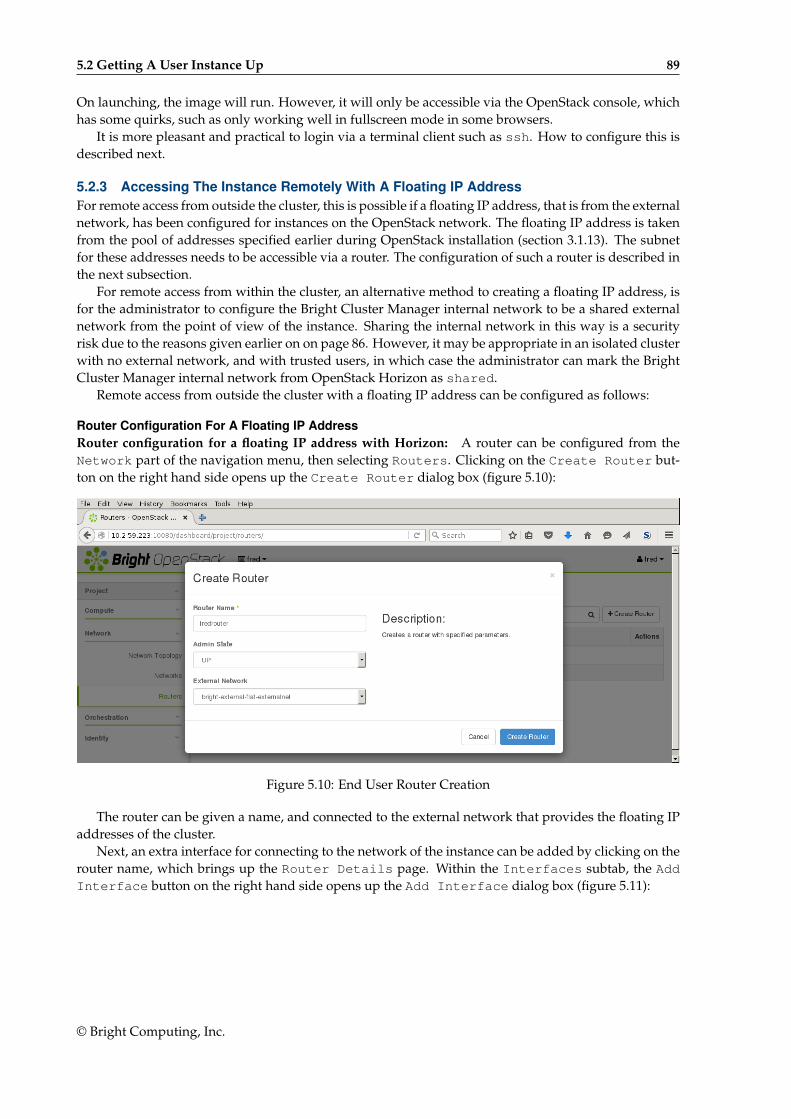
5.2 Getting A User Instance Up 89
On launching, the image will run. However, it will only be accessible via the OpenStack console, whichhas some quirks, such as only working well in fullscreen mode in some browsers.
It is more pleasant and practical to login via a terminal client such as ssh. How to configure this isdescribed next.
5.2.3 Accessing The Instance Remotely With A Floating IP AddressFor remote access from outside the cluster, this is possible if a floating IP address, that is from the externalnetwork, has been configured for instances on the OpenStack network. The floating IP address is takenfrom the pool of addresses specified earlier during OpenStack installation (section 3.1.13). The subnetfor these addresses needs to be accessible via a router. The configuration of such a router is described inthe next subsection.
For remote access from within the cluster, an alternative method to creating a floating IP address, isfor the administrator to configure the Bright Cluster Manager internal network to be a shared externalnetwork from the point of view of the instance. Sharing the internal network in this way is a securityrisk due to the reasons given earlier on on page 86. However, it may be appropriate in an isolated clusterwith no external network, and with trusted users, in which case the administrator can mark the BrightCluster Manager internal network from OpenStack Horizon as shared.
Remote access from outside the cluster with a floating IP address can be configured as follows:
Router Configuration For A Floating IP AddressRouter configuration for a floating IP address with Horizon: A router can be configured from theNetwork part of the navigation menu, then selecting Routers. Clicking on the Create Router but-ton on the right hand side opens up the Create Router dialog box (figure 5.10):
Figure 5.10: End User Router Creation
The router can be given a name, and connected to the external network that provides the floating IPaddresses of the cluster.
Next, an extra interface for connecting to the network of the instance can be added by clicking on therouter name, which brings up the Router Details page. Within the Interfaces subtab, the AddInterface button on the right hand side opens up the Add Interface dialog box (figure 5.11):
© Bright Computing, Inc.
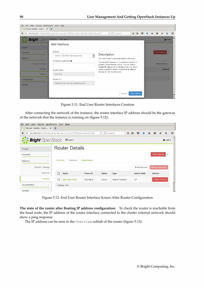
90 User Management And Getting OpenStack Instances Up
Figure 5.11: End User Router Interfaces Creation
After connecting the network of the instance, the router interface IP address should be the gatewayof the network that the instance is running on (figure 5.12):
Figure 5.12: End User Router Interface Screen After Router Configuration
The state of the router after floating IP address configuration: To check the router is reachable fromthe head node, the IP address of the router interface connected to the cluster external network shouldshow a ping response.
The IP address can be seen in the Overview subtab of the router (figure 5.13):
© Bright Computing, Inc.
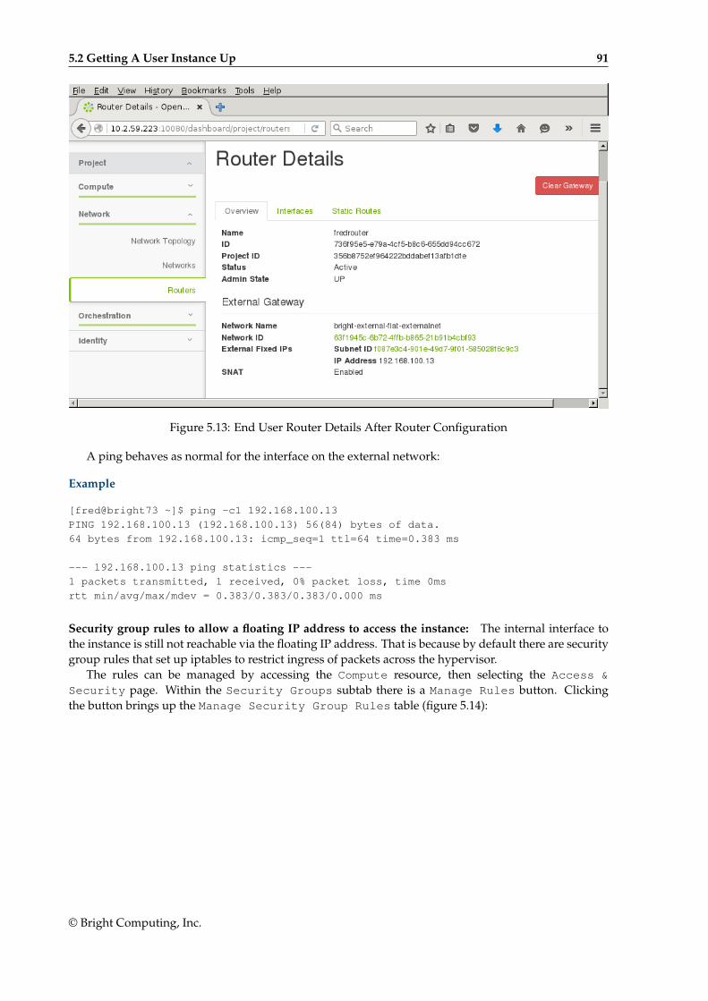
5.2 Getting A User Instance Up 91
Figure 5.13: End User Router Details After Router Configuration
A ping behaves as normal for the interface on the external network:
Example
[fred@bright73 ~]$ ping -c1 192.168.100.13
PING 192.168.100.13 (192.168.100.13) 56(84) bytes of data.
64 bytes from 192.168.100.13: icmp_seq=1 ttl=64 time=0.383 ms
--- 192.168.100.13 ping statistics ---
1 packets transmitted, 1 received, 0% packet loss, time 0ms
rtt min/avg/max/mdev = 0.383/0.383/0.383/0.000 ms
Security group rules to allow a floating IP address to access the instance: The internal interface tothe instance is still not reachable via the floating IP address. That is because by default there are securitygroup rules that set up iptables to restrict ingress of packets across the hypervisor.
The rules can be managed by accessing the Compute resource, then selecting the Access &Security page. Within the Security Groups subtab there is a Manage Rules button. Clickingthe button brings up the Manage Security Group Rules table (figure 5.14):
© Bright Computing, Inc.
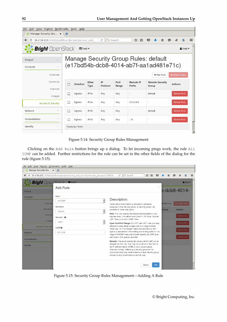
92 User Management And Getting OpenStack Instances Up
Figure 5.14: Security Group Rules Management
Clicking on the Add Rule button brings up a dialog. To let incoming pings work, the rule AllICMP can be added. Further restrictions for the rule can be set in the other fields of the dialog for therule (figure 5.15).
Figure 5.15: Security Group Rules Management—Adding A Rule
© Bright Computing, Inc.
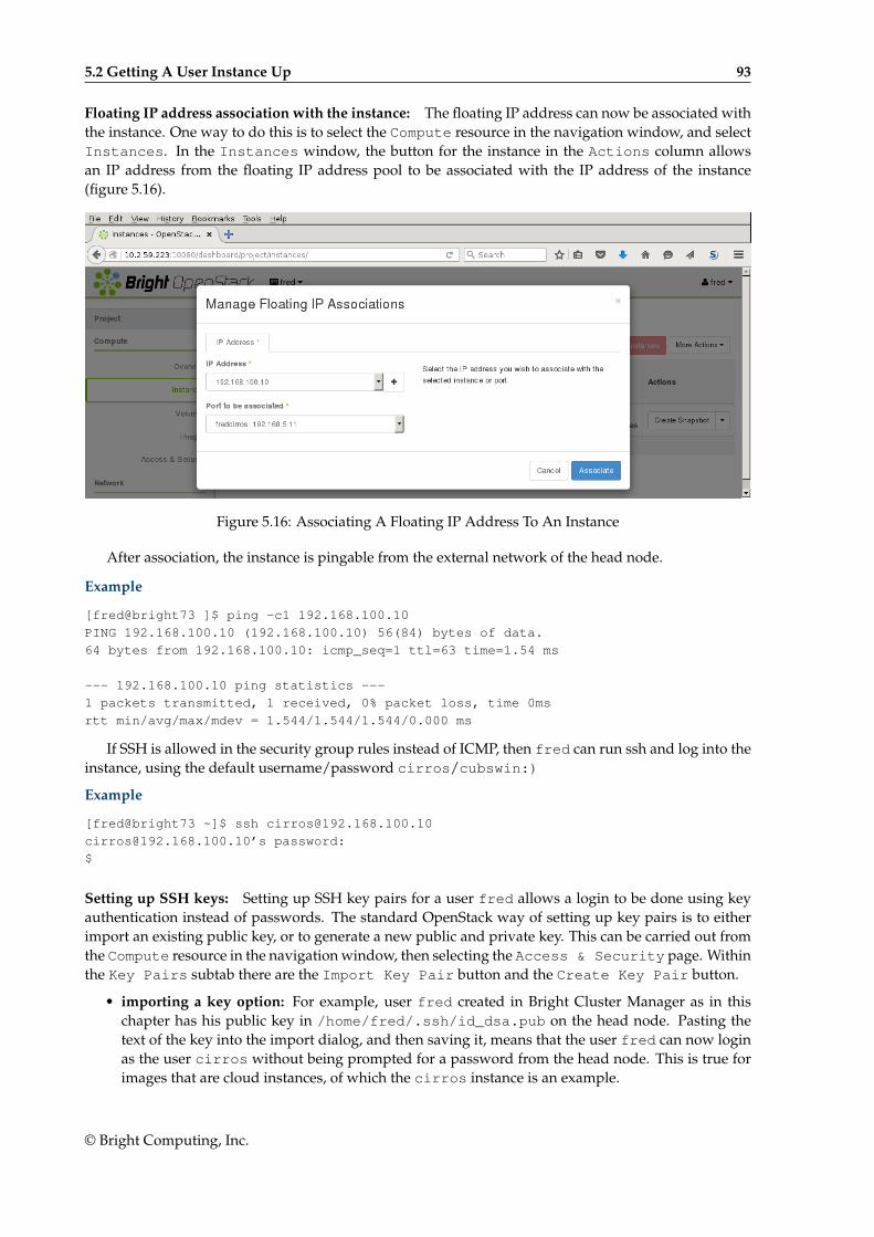
5.2 Getting A User Instance Up 93
Floating IP address association with the instance: The floating IP address can now be associated withthe instance. One way to do this is to select the Compute resource in the navigation window, and selectInstances. In the Instances window, the button for the instance in the Actions column allowsan IP address from the floating IP address pool to be associated with the IP address of the instance(figure 5.16).
Figure 5.16: Associating A Floating IP Address To An Instance
After association, the instance is pingable from the external network of the head node.
Example
[fred@bright73 ]$ ping -c1 192.168.100.10
PING 192.168.100.10 (192.168.100.10) 56(84) bytes of data.
64 bytes from 192.168.100.10: icmp_seq=1 ttl=63 time=1.54 ms
--- 192.168.100.10 ping statistics ---
1 packets transmitted, 1 received, 0% packet loss, time 0ms
rtt min/avg/max/mdev = 1.544/1.544/1.544/0.000 ms
If SSH is allowed in the security group rules instead of ICMP, then fred can run ssh and log into theinstance, using the default username/password cirros/cubswin:)
Example
[fred@bright73 ~]$ ssh [email protected]
[email protected]’s password:
$
Setting up SSH keys: Setting up SSH key pairs for a user fred allows a login to be done using keyauthentication instead of passwords. The standard OpenStack way of setting up key pairs is to eitherimport an existing public key, or to generate a new public and private key. This can be carried out fromthe Compute resource in the navigation window, then selecting the Access & Security page. Withinthe Key Pairs subtab there are the Import Key Pair button and the Create Key Pair button.
• importing a key option: For example, user fred created in Bright Cluster Manager as in thischapter has his public key in /home/fred/.ssh/id_dsa.pub on the head node. Pasting thetext of the key into the import dialog, and then saving it, means that the user fred can now loginas the user cirros without being prompted for a password from the head node. This is true forimages that are cloud instances, of which the cirros instance is an example.
© Bright Computing, Inc.

94 User Management And Getting OpenStack Instances Up
• creating a key pair option: Here a pair of keys is generated for a user. A PEM container file withjust the private key <PEM file>, is made available for download to the user, and should be placed ina directory accessible to the user, on any host machine that is to be used to access the instance. Thecorresponding public key is stored in Keystone, and the private key discarded by the generatingmachine. The downloaded private key should be stored where it can be accessed by ssh, andshould be kept read and write only. If its permissions have changed, then running chmod 600<PEM file> on it will make it compliant. The user can then login to the instance using, for example,ssh -i <PEM file> [email protected], without being prompted for a password.
The openstack keypair options are the CLI API equivalent for the preceding Horizon operations.Setting up SSH key pairs in this way relies on a properly functioning cloud-init. cloud-init is
a set of initialization utilities that is part of the image available for the VMs that run under OpenStack(section 5.2.1). It is cloud-init that gets the VMs contact the OpenStack metadata server to pick upthe public key and place it in the proper location on the VMs.
5.3 Running A Bright-managed InstanceA Bright-managed instance is a special case of the user instance in section 5.2. A Bright-managed in-stance is a virtual machine that is treated very similarly to a regular node by Bright Cluster Manager, andruns by default as a vnode. For example, it runs with the default names of vnode001, vnode002...rather than a node001, node002 and so on. The default number of vnodes that is set, if Bright-managed instances are enabled, is 5, altough this number can be altered during OpenStack installation.The number of vnodes can be modified after installation in several ways, including:
• by adding a vnode as a node of type virtualnode
• by cloning an existing vnode and modifying it if needed
• by running the Create Nodes wizard in the Virtual Nodes tabbed pane. This is accessiblefrom the OpenStack resource.
Since Bright Cluster Manager is integrated tightly with vnodes, getting a Bright-managed instancerunning is much easier than the procedure for user instances described earlier in sections 5.1 and 5.2.It is also a cluster administrator that typically creates Bright-managed instances, which run under thebright project, whereas it is end users that typically create regular VM instances, which typically rununder a non-bright project name.
To get a default vnode up, it can be powered up from cmsh:
Example
[root@bright73 ~]# cmsh -c "device power on vnode001"
or it can be powered up from cmgui by right-clicking on the vnodes under the OpenStack resource,and selecting the Power On option (figure 5.17):
© Bright Computing, Inc.
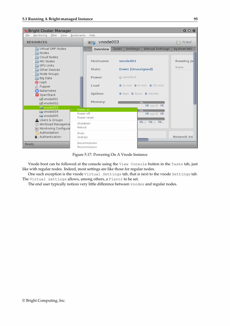
5.3 Running A Bright-managed Instance 95
Figure 5.17: Powering On A Vnode Instance
Vnode boot can be followed at the console using the View Console button in the Tasks tab, justlike with regular nodes. Indeed, most settings are like those for regular nodes.
One such exception is the vnode Virtual Settings tab, that is next to the vnode Settings tab.The Virtual settings allows, among others, a Flavor to be set.
The end user typically notices very little difference between vnodes and regular nodes.
© Bright Computing, Inc.