Embed Size (px)
Citation preview

2 | August 2010
Delhi Office
SOUTH PRECISION INSTRUMENT PVT. LTD. Add:1108-09-10-11, 11th Floor, RG Tower, Plot No-B-7,
Netaji Subhash Place, Pitam Pura, New Delhi-110034 Tel: +91-11-49995999, 64563666, 9999999255
Fax: +91-11-45605999
Delhi Office
SOUTH PRECISION INSTRUMENT PVT. LTD. Add:1108-09-10-11, 11th Floor, RG Tower, Plot No-B-7,
Netaji Subhash Place, Pitam Pura, New Delhi-110034 Tel: +91-11-49995999, 64563666, 9999999255
Fax: +91-11-45605999
http://www.southinstrument.comhttp: / / in .southinstrument.com
Opening ceremony
coming soon,
south invite you share
the great moment with us
Opening ceremony
coming soon,
south invite you share
the great moment with us
Mumbai Office
SOUTH PRECISION INSTRUMENT PVT.LTD. Add: A--103, Om Shivam center,
Plot No: A-33+34, Sector-20, Opp- Nerul Rly Station, Nerul, Navi Mumbai-400706
22-32210052Mob: 9766329600
Tel: +91-
Kolkata Office
SOUTH PRECISION INSTRUMENT PVT.LTD. Add: CD-225, Ground floor,Bidhan Nagar,
Sect-1, Salt Lake City, Kolkata-700064 Fax: +91-33-40621099
Mob: 9681840246, 9007002404
Hyderabad Office
SOUTH PRECISION INSTRUMENT PVT.LTD. Add: Flat NO- 101,Sai Mitra Construction
10-3-55/1,BehindSBI Bank, Maredpally East, Secunderabad-500026
Tel: +91-40-42226269Fax: +91-40-27734723
Mob: 9891197687, 9293105206

August 2010 | 3
It’s not just a picture.
It’s image data.to fuel vital insights.
Lat: 42° 42’ 27’’ N Long: 133° 01’ 24’’ E
06.10.09 Resolution: .50m CE90%:4m
Access the world’s most accurate high-resolution commercial imagery. At GeoEye, we’re providing global companies in diverse markets, including oil and gas, with Information Services backed by unrivaled knowledge, experience and technical capabilities. From infrastructure development to site management to risk mitigation, GeoEye enables you to oversee critical assets more efficiently by providing timely, relevant location information and image-based insight. To see what a trusted and proven partner can do for you, contact GeoEye.
Image intell igence. Delivered intell igently.
www.geoeye.com / svc
© 2010 GeoEye. All Rights Reserved.
4 | August 2010
Volume 6, Issue 8, August 2010
colophon And contents
Mailing Address
11C Pocket A
SFS Mayur Vihar Phase III
Delhi 110 096, India.
Phones +91 11 22632607, 98102 33422, 98107 24567
Fax +91 11 22632607
[information][email protected]
[editorial][email protected]
[advertising][email protected]
[subscriptions][email protected]
Web www.mycoordinates.org
Coordinates is an initiative of cGIT that aims to broaden the
scope of positioning, navigation and related technologies.
cGIT does not neccesarily subscribe to the views expressed
by the authors and advertisers in this magazine and may not
be held liable for any losses caused directly or indirectly due
to the information provided herein. © cGIT, 2009. Reprinting
with permission is encouraged; contact the editor for details.
Annual subscription (12 issues) [India] Rs.1,200
[Overseas] US$80
printed and published by Sanjay Malaviya on behalf of Centre
for Geoinformation Technologies at A221 Mangal
Apartments, Vasundhara Enclave, Delhi 110096, India.
editor Bal Krishna
owner Centre for Geoinformation Technologies
designed at Thomson Press India Ltd.
printer Thomson Press India Ltd., B 315, Okhla Phase I,
New Delhi-110020, India
this issue of coordinates is of 44 pages, including
cover
Articles
phase centre determination on the basis of far-field measurements Nikola Basta, aNdriy koNovaltsev aNd
lukasz a Greda 7 GpR data georeferencing using photogrammetry and digital maps BarzaGhi riccardo,
carrioN daNiela, cazzaNiGa Noemi emaNuela aNd ForlaNi GiaNFraNco 12 Geo-spatial data accuracy and its legal implications adiBah awaNG, shahidah mohd ariFF aNd ahmad Fauzi NordiN 27 Into the orbit: latest Indian Rs satellite and a ‘dream’ of students 32
columnsMy coordinates editorial 6 his coordinates JohN Pottle 11, v P aGrawal 16 kr sridhara murthi 33 news GPs
34 lBs 35 Galileo uPdate 36 lBs 39 remote seNsiNG 38 Gis 38 iNdustry 39 Mark your calendar sePtemBer 2010 to
NovemBer 2011 42
this issue has been made possible by the support and good wishes of the following individuals and companies Adibah Awang, Ahmad Fauzi Nordin, Andriy Konovaltsev, Barzaghi Riccardo, Carrion Daniela, Cazzaniga Noemi Emanuela, Forlani Gianfranco, John Pottle, KR Sridhara Murthi, Lukasz A Greda, Nikola Basta, Shahidah Mohd Ariff, V P Agrawal and Ashtech, GeoEye, Foif, Hemisphere GPS, Javad, Navcom, NovAtel, Sanding, South, and many others.
In this issue

August 2010 | 5
Affordable GIS/GPS with nothing missing
MobileMapper™ 6True Mobile GIS for Everyone
MobileMapper 6 provides a complete set of all necessary features required of a mapping device for anyone who needs productive data collection and efficient asset management in the field. Through post-processing, the positionsof every GIS feature you collect can be better than meter-level accuracy.
Together with the new MobileMapper Field and Office software, you will get a cost-effective, easy-to-use mapping application including new features thatfulfill professional GIS requirements: Direct interface to Laser Technologydevices automatically updates offsets. Capability to export to KML formatallows plotting collected data on the Google Earth maps.
The MobileMapper 6 comes with Microsoft Windows Mobile 6, a color touch-screen, and has Bluetooth for wireless connectivity. This handy feature-richGPS includes an integrated 2-megapixel camera, an embedded speaker andmicrophone to enrich the collected data with pictures and voice notes.
Contact us today to receive the white paper and read how MobileMapper 6 beats its competition. Visit www.ashtech.com or email [email protected]
Features• High-sensitivity GPS• Rugged and waterproof• Windows Mobile 6• 2-megapixel digital camera• Bluetooth connectivity• Submeter post-processing
©2010 Ashtech LLC. All rights reserved. The Ashtech logo and MobileMapper are trademarks of Ashtech, LLC. All other products and brand names are trademarks of their respective holders.
For more information:
France(HQ) +33 2 28 09 38 00China +86 10 5802 5174APAC +65 983 842 29

6 | August 2010
Bal Krishna, [email protected]
AdVIsoRs Naser El-Sheimy PEng, CRC Professor, Department of Geomatics Engineering, The University of Calgary Canada, George Cho
Professor in GIS and the Law, University of Canberra, Australia, Associate Professor Abbas Rajabifard Director, Centre for SDI and Land
Administration, University of Melbourne, Australia, Luiz Paulo Souto Fortes PhD Associate Director of Geosciences, Brazilian Institute of
Geography and Statistics -IBGE, Brazil, John Hannah Professor, School of Surveying, University of Otago, New Zealand
MycooRdInAtes
Finally, the FOP!
India has launched the Final Operation Phase (FOP) of GAGAN.
The process of certification for aviation use is expected to be completed by 2013.
As a very large user segment in this region awaits.
Air navigation space in and around India is set to be redefined.
With many more applications beyond aviation.
In a multi-GNSS world,
India strives be a player.
And a contributor to the technology.
The focus remains on ‘complementing’
What about the competition?
August 2010 | 7
nikola Basta DLR, German Aerospace CenterGermany
Andriy Konovaltsev DLR, German Aerospace CenterGermany
lukasz A. Greda DLR, German Aerospace CenterGermany
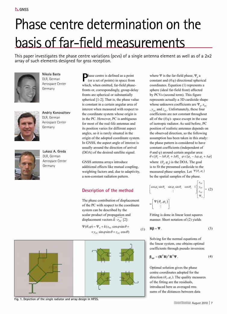
Phase centre determination on the basis of far-field measurementsThis paper investigates the phase centre variations (pcvs) of a single antenna element as well as of a 2x2 array of such elements designed for gnss reception.
Gnss
Phase centre is defined as a point (or a set of points) in space from
which, when emitted, far-field phase-fronts or, correspondingly, group-delay fronts are spherical or substantially spherical [1-2]. That is, the phase value is constant in a certain angular area of interest when measured with respect to the coordinate system whose origin is in the PC. However, PC is ambiguous for most of the real-life antennas and its position varies for different aspect angles, so it is rarely situated in the origin of the adopted coordinate system. In GNSS, the aspect angle of interest is usually around the direction of arrival (DOA) of the desired satellite signal.
GNSS antenna arrays introduce additional effects like mutual coupling, weighting factors and, due to adaptivity, a non-constant radiation pattern.
description of the method
The phase contribution of displacement of the PC with respect to the coordinate system can be described by the scalar product of propagation and displacement vectors [2]:
(1)
where Ψ is the far-field phase, Ψ0 a constant and (θ,ϕ) directional spherical coordinates. Equation (1) represents a sphere (ideal far-field front) affected by PCVs (second term). This figure represents actually a 3D cardioide shape whose unknown coefficients are Ψ0, xPC , yPC and zPC. Unfortunately, these four coefficients are not constant throughout all of the (θ,ϕ)- space except in the case of isotropic radiator. As said before, PC position of realistic antennas depends on the observed direction, so the following assumption has been taken in this study: the phase pattern is considered to have constant coefficients (independent of θ and ϕ) around certain angular area:
, where (θd ,ϕd) is the DOA. The goal is to fit the presumed cardioide to the measured phase samples. Let be the spatial samples of the phase.
(2)
Fitting is done in linear least squares manner. Short notation of (2) yields
(3)
Solving for the normal equations of the linear system, one obtains optimal coefficients through pseudo inversion:
(4)
Optimal solution gives the phase centre coordinates adopted for the direction . The quality measures of the fitting are the residuals, introduced here as averaged rms sums of the distances between data
Fig. 1. depiction of the single radiator and array design in hFss.

8 | August 2010
points and fitted curve or surface:
(5)
where N is the number of sample points enclosed by the solid angle range.
parameters of the antennas
The radiator is a right hand circularly polarised (RHCP) square patch antenna, designed for operation in L1 band (1.575 GHz) [4]. The antenna is fed through two slots in the ground plane, which are excited by microstrip lines.
The array consists of four such patches arranged in a 2x2 configuration with sequential rotation feeding scheme. Hereby each successive element is rotated 90° in circular manner and the initial signal phases of the elements are also accordingly incremented by 90°. This results in improved axial ratio for the desired polarisation (RHCP).
simulation setup
Simulations are conducted in Ansoft HFSS™ commercial tool and then imported to MATLAB®, for calculation of PC. The patterns are recorded with 1° resolution in both θ and ϕ coordinate. Because of the planar configuration of the antennas, zenith angle has been observed in each ϕ-cut.
A solid angle for determination of PC is defined as shown in Fig. 2 in a polar coordinates representation. For a given direction (θd, φd ) blue circular area takes into account all data points of the antenna far-field phase which fall in it. The angular range of the tested area should be large enough to eliminate the noisy effects of the measurement but also sufficiently small for representing the local PCV effects.
For accurate estimation of the phase centre, one must first acquire the phase front data points with as less bias as possible. A typical bias is azimuthal linear trend of the antenna far-field phase incorporated
in RHCP. This can be described by ΨRHCP = – φ + const. So in order to consider all of the directions equally this trend has to be compensated in the calculations by normalising for zenith direction.
simulation of a single radiator
For the following simulations, an arbitrary angular test range of 20° was taken. Due to the feeding method (Fig. 1), simulated phase pattern of the patch antenna is asymmetrical as shown in Fig. 3. A set of directions for PC determination was defined as a single cut by: φ=0° and
Fig. 5. The results show that PC is stable and stays within a 10 mm range for most of the chosen directions accept for the ones close to the horizon (Fig. 4).
simulation of the array
Since the structure designed in HFSS™ is rotationally symmetrical, only one of the four radiators was excited in the simulation, thus the pattern of a single radiator together with the mutual coupling effects was obtained. This allows acquiring of the total array pattern and beamforming in software (MATLAB®). The main beam direction was steered to θmax = 45°, φmax = 45°.
It is evident that the array phase pattern has discontinuities where amplitude pattern has zeros (Fig. 5). These phase shifts are often difficult to filter
out performing unwrapping, due to the slow transition of the phase in space.
For this study, focus was on the determination of the phase centre in the area where the radiation is significant (main beam). In that area, results show mild PCV within ± 40 mm (Fig. 6).
Measurement setup
In the measurement, the same geometrical setup has been used as in previous
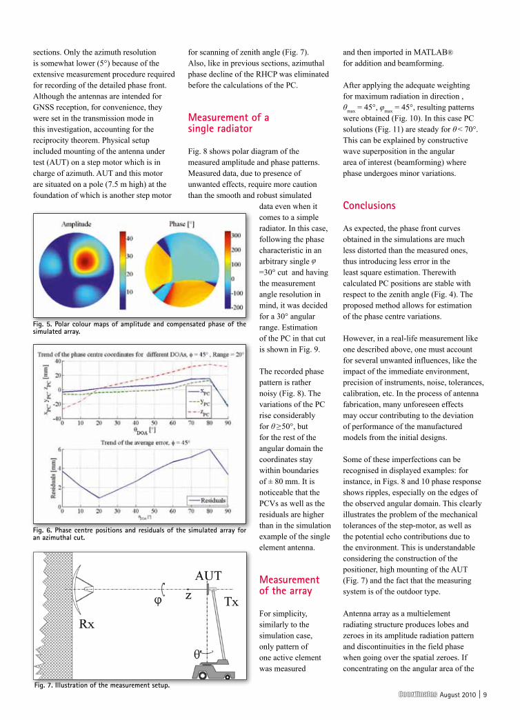
Fig. 4. phase centre positions and residuals of the simulated single patch for an azimuthal cut.
Fig. 3. polar colour maps of amplitude and compensated phase of a simulated single patch.
Fig. 2. polar diagram used for sampling of the phase pattern.
August 2010 | 9
sections. Only the azimuth resolution is somewhat lower (5°) because of the extensive measurement procedure required for recording of the detailed phase front. Although the antennas are intended for GNSS reception, for convenience, they were set in the transmission mode in this investigation, accounting for the reciprocity theorem. Physical setup included mounting of the antenna under test (AUT) on a step motor which is in charge of azimuth. AUT and this motor are situated on a pole (7.5 m high) at the foundation of which is another step motor
for scanning of zenith angle (Fig. 7). Also, like in previous sections, azimuthal phase decline of the RHCP was eliminated before the calculations of the PC.
Measurement of a single radiator
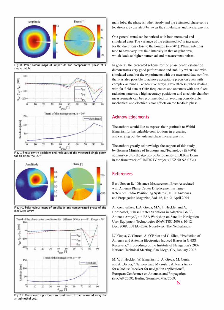
Fig. 8 shows polar diagram of the measured amplitude and phase patterns. Measured data, due to presence of unwanted effects, require more caution than the smooth and robust simulated
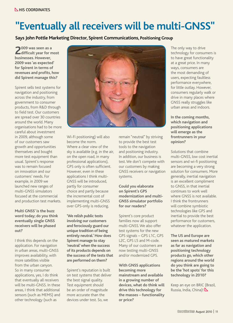
data even when it comes to a simple radiator. In this case, following the phase characteristic in an arbitrary single φ =30° cut and having the measurement angle resolution in mind, it was decided for a 30° angular range. Estimation of the PC in that cut is shown in Fig. 9.
The recorded phase pattern is rather noisy (Fig. 8). The variations of the PC rise considerably for θ ≥50°, but for the rest of the angular domain the coordinates stay within boundaries of ± 80 mm. It is noticeable that the PCVs as well as the residuals are higher than in the simulation example of the single element antenna.
Measurement of the array
For simplicity, similarly to the simulation case, only pattern of one active element was measured
and then imported in MATLAB® for addition and beamforming.
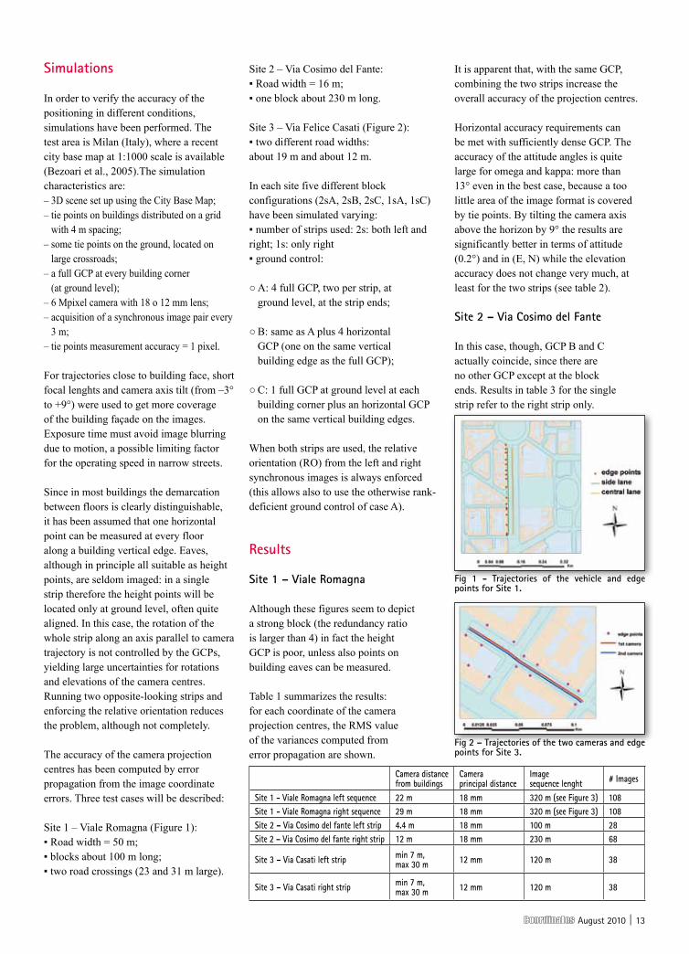
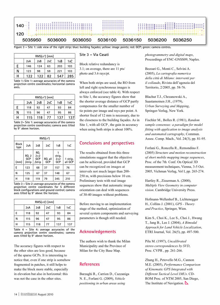
After applying the adequate weighting for maximum radiation in direction , θmax = 45°, φmax = 45°, resulting patterns were obtained (Fig. 10). In this case PC solutions (Fig. 11) are steady for θ < 70°. This can be explained by constructive wave superposition in the angular area of interest (beamforming) where phase undergoes minor variations.
conclusions
As expected, the phase front curves obtained in the simulations are much less distorted than the measured ones, thus introducing less error in the least square estimation. Therewith calculated PC positions are stable with respect to the zenith angle (Fig. 4). The proposed method allows for estimation of the phase centre variations.
However, in a real-life measurement like one described above, one must account for several unwanted influences, like the impact of the immediate environment, precision of instruments, noise, tolerances, calibration, etc. In the process of antenna fabrication, many unforeseen effects may occur contributing to the deviation of performance of the manufactured models from the initial designs.
Some of these imperfections can be recognised in displayed examples: for instance, in Figs. 8 and 10 phase response shows ripples, especially on the edges of the observed angular domain. This clearly illustrates the problem of the mechanical tolerances of the step-motor, as well as the potential echo contributions due to the environment. This is understandable considering the construction of the positioner, high mounting of the AUT (Fig. 7) and the fact that the measuring system is of the outdoor type.
Antenna array as a multielement radiating structure produces lobes and zeroes in its amplitude radiation pattern and discontinuities in the field phase when going over the spatial zeroes. If concentrating on the angular area of the
Fig. 6. phase centre positions and residuals of the simulated array for an azimuthal cut.
Fig. 5. polar colour maps of amplitude and compensated phase of the simulated array.
Fig. 7. Illustration of the measurement setup.
10 | August 2010
main lobe, the phase is rather steady and the estimated phase centre locations are consistent between the simulations and measurements.
One general trend can be noticed with both measured and simulated data. The variance of the estimated PC is increased for the directions close to the horizon (θ = 90°). Planar antennas tend to have very low field intensity in that angular area, which leads to higher numerical and measurement noises.
In general, the presented scheme for the phase centre estimation demonstrates very good performance and stability when used with simulated data, but the experiments with the measured data confirm that it is also possible to achieve acceptable precision even with complex antennas like adaptive arrays. Nevertheless, when dealing with far-field data at GHz-frequencies and antennas with non-fixed radiation patterns, a high accuracy positioner and anechoic chamber measurements can be recommended for avoiding considerable mechanical and electrical error effects on the far-field phase.
Acknowledgements
The authors would like to express their gratitude to Wahid Elmarissi for his valuable contributions in preparing and carrying out the antenna phase measurements.
The authors greatly acknowledge the support of this study by German Ministry of Economy and Technology (BMWi) administered by the Agency of Aeronautics of DLR in Bonn in the framework of UniTaS IV project (FKZ 50 NA 0734).
References
Best, Steven R. “Distance-Measurement Error Associated with Antenna Phase-Center Displacement in Time-Reference Radio Positioning Systems”, IEEE Antennas and Propagation Magazine, Vol. 46, No. 2, April 2004.
A. Konovaltsev, L.A. Greda, M.V. T. Heckler and A. Hornbostel, “Phase Center Variations in Adaptive GNSS Antenna Arrays”, 4th ESA Workshop on Satellite Navigation User Equipment Technologies (NAVITEC’2008), 10-12 Dec. 2008, ESTEC-ESA, Noordwijk, The Netherlands.
I.J. Gupta, C. Church, A. O’Brien and C. Slick, “Prediction of Antenna and Antenna Electronics Induced Biases in GNSS Receivers,” Proceedings of the Institute of Navigation’s 2007 National Technical Meeting, San Diego, CA, January 2007.
M. V. T. Heckler, W. Elmarissi, L. A. Greda, M. Cuntz, and A. Dreher, “Narrow-band Microstrip Antenna Array for a Robust Receiver for navigation applications”, European Conference on Antennas and Propagation (EuCAP 2009), Berlin, Germany, Mar. 2009.
Fig. 11. phase centre positions and residuals of the measured array for an azimuthal cut.
Fig. 10. polar colour maps of amplitude and compensated phase of the measured array.
Fig. 9. phase centre positions and residuals of the measured single patch for an azimuthal cut.
Fig. 8. polar colour maps of amplitude and compensated phase of a single patch.
August 2010 | 11
2009 was seen as a difficult year for most
businesses. However, 2009 was ‘as expected’ for Spirent in terms of revenues and profits, how did Spirent manage this?
Spirent sells test systems for navigation and positioning across the industry, from government to consumer products, from R&D through to field test. Our customers are spread over 30 countries around the world. Many organisations had to be more careful about investment in 2009, although some of our customers saw growth and opportunities themselves and bought more test equipment than usual. Spirent’s response was to remain focused on innovation and our customers’ needs. For example, in 2009 we launched new ranges of multi-GNSS simulators focused at the commercial and production test markets.
Multi GNSS’ is the buzz word today; do you think eventually single GNSS receivers will be phased out?
I think this depends on the application. For navigation in urban areas, multi-GNSS improves availability, with more satellites visible from the urban canyon. So in many consumer applications, yes, I do think that eventually all receivers will be multi-GNSS. In these areas, I think that additional sensors (such as MEMS) and other technology (such as
Wi-Fi positioning) will also become the norm. Where a clear view of the sky is available (e.g. in the air, on the open road, in many professional applications), GPS only is often sufficient. However, even in these applications I think multi-GNSS will be introduced, partly for consumer choice and partly because the incremental cost of implementing multi-GNSS over GPS-only is reducing.
‘We relish public tests involving our customers and ferociously guard our unique tradition of being entirely neutral.’ How does Spirent manage to stay ‘neutral’ when the success of its products depends on the success of the tests that are performed on them?
Spirent’s reputation is built on test systems that deliver the best signal quality. Test equipment should be an order of magnitude more accurate than the devices under test. So, we
remain “neutral” by striving to provide the best test tools to the navigation and positioning industry. In addition, our business is test. We don’t compete with our customers by making GNSS receivers or navigation systems.
Could you elaborate on Spirent’s GPS modernization and multi-GNSS simulator portfolio for our readers?
Spirent’s core product families now all support multi-GNSS. We also offer test systems for the new GPS signals – GPS L1C, GPS L2C, GPS L5 and M-code. Many of our customers are now testing multi-GNSS and/or modernized GPS.
With GNSS applications becoming more mainstream and available in a growing number of devices, what do think will drive this technology for the masses – functionality or price?
The only way to drive technology for consumers is to have great functionality at a great price. In many ways, consumers are the most demanding of users, expecting faultless performance everywhere, for little outlay. However, consumers regularly walk or drive in many places where GNSS really struggles like urban areas and indoors.
In the coming months, which navigation and positioning applications will emerge as the frontrunners in your opinion?
Solutions that combine multi-GNSS, low cost inertial sensors and wi-fi positioning are becoming a very strong solution for consumers. More generally, inertial navigation is an excellent compliment to GNSS, in that inertial continues to work well where GNSS is not available. I think the frontrunners will combine symbiotic technologies like GPS and inertial to provide the best performance for customers, whatever the application.
The US and Europe are seen as matured markets as far as navigation and positioning technology products go, which other regions around the world do you think are going to be the ‘hot spots’ for this technology in 2010?
Keep an eye on BRIC (Brazil, Russia, India, China)!
"Eventually all receivers will be multi-GNSS" Says John Pottle Marketing Director, Spirent Communications, Positioning Group
hIs cooRdInAtes
August 2010 | 11

12 | August 2010
suRVeyInG
Ground Penetrating Radar (GPR) provides a picture of the different
materials or structures underground up to a few meters of depth. To provide a 3D map of underground objects such as pipelines, the georeferencing horizontal tolerance should be around 20 cm, a figure achievable by GNSS systems. The conditions of GPR urban surveys, though, make it impossible to rely on GPS alone for positioning. In front of large blocks, in narrow streets, or in tree-lined avenues GPS is not sufficient to guarantee uninterrupted coverage. To overcome the problem, systems combining GPS and inertial navigation can be used (Zhang et al., 2005) although rather expensive. Another possibility is to use photogrammetry to georeference the GPR trailer. This paper presents the first results of a feasibility study of a system where photogrammetry, digital maps and GPS are combined to georeference GPR surveys.
Georeferencing by photogrammetry
The GPR-trailer will host at least a pair of reflex digital medium resolution cameras, installed on a rigid frame, high enough to minimize occlusions by parked cars and looking leftwards and rightwards; each will acquire a strip of the building façades at the side. A GPS antenna will be mounted on the top of the frame. Data acquisition from the different sensors will be synchronized, in order to allow time interpolation of the trajectory; cameras will be triggered by an odometer; calibration will account for lever arms and misalignments between the sensors.
Tie points along each strip will be automatically extracted and matched by a robust Structure and Motion algorithm
(Pilu, 1997; Fischler and Bolles, 1981; Hartley and Zisserman, 2000; Forlani, Roncella, Remondino, 2005). Using calibrated cameras, the orientation of each pair in an arbitrary metric frame can be recovered through the essential matrix; approximate point coordinates can be computed by forward intersection using a linear algorithm. By alternating intersection and resection, each strip will be oriented in an arbitrary frame.
Maps standards prescribe a 95% tolerance of 40 cm for 1:1000 scale (Blachut et al., 1979): therefore map points may be used as GCPs to georeference the photogrammetric strip. Full (3D) GCPs can be easily recognized and measured on the images at building block corners (at ground level); 2D GCPs can also be measured along vertical edges of a building.
Since the accuracy of the perspective centres decreases along the strip with the distance from the closest GCP, the relative orientation (RO) and the distance between left and right cameras, known by calibration, can be enforced, to constrain the solution.
A final bundle adjustment will provide the projection centres of the images, combining the available information: the GCP coordinates, the relative orientation constraint, any available GPS position.
As long as the camera records building façades, tie points will be extracted and matched seamlessly, because of the rich texture and optimal viewing geometry. When crossing large roads or squares, though, finding tie points is difficult. If the GPS position is available, no photogrammetric solution is necessary; otherwise manual measurements must be used to improve tie point distribution.
Barzaghi Riccardo Professor, DIIAR, Politecnico di Milano, Milan, Italy
cazzaniga noemi emanuelaResearch Fellow, DIIAR, Politecnico di Milano, Milan, Italy
carrion danielaDIIAR, Politecnico di Milano, Milan, Italy.
Forlani Gianfranco, Professor, Dipartimento di Ingegneria Civile, Università di Parma, Parma, Italy
GPR data georeferencing using photogrammetry and digital mapsThis paper presents the first results of a feasibility study of a system where photogrammetry, digital maps and GPS are combined to georeference GPR surveys
August 2010 | 13
simulations
In order to verify the accuracy of the positioning in different conditions, simulations have been performed. The test area is Milan (Italy), where a recent city base map at 1:1000 scale is available (Bezoari et al., 2005).The simulation characteristics are: – 3D scene set up using the City Base Map; – tie points on buildings distributed on a grid – with 4 m spacing;– some tie points on the ground, located on – – – large crossroads;– a full GCP at every building corner – (at ground level);– 6 Mpixel camera with 18 o 12 mm lens; – acquisition of a synchronous image pair every – 3 m;– tie points measurement accuracy = 1 pixel.
For trajectories close to building face, short focal lenghts and camera axis tilt (from –3° to +9°) were used to get more coverage of the building façade on the images. Exposure time must avoid image blurring due to motion, a possible limiting factor for the operating speed in narrow streets.
Since in most buildings the demarcation between floors is clearly distinguishable, it has been assumed that one horizontal point can be measured at every floor along a building vertical edge. Eaves, although in principle all suitable as height points, are seldom imaged: in a single strip therefore the height points will be located only at ground level, often quite aligned. In this case, the rotation of the whole strip along an axis parallel to camera trajectory is not controlled by the GCPs, yielding large uncertainties for rotations and elevations of the camera centres. Running two opposite-looking strips and enforcing the relative orientation reduces the problem, although not completely.
The accuracy of the camera projection centres has been computed by error propagation from the image coordinate errors. Three test cases will be described:
Site 1 – Viale Romagna (Figure 1): ▪ Road width = 50 m; ▪ blocks about 100 m long; ▪ two road crossings (23 and 31 m large).
Site 2 – Via Cosimo del Fante: ▪ Road width = 16 m; ▪ one block about 230 m long.
Site 3 – Via Felice Casati (Figure 2): ▪ two different road widths: about 19 m and about 12 m.
In each site five different block configurations (2sA, 2sB, 2sC, 1sA, 1sC) have been simulated varying: ▪ number of strips used: 2s: both left and right; 1s: only right ▪ ground control:
○ A: 4 full GCP, two per strip, at ground level, at the strip ends;
○ B: same as A plus 4 horizontal GCP (one on the same vertical building edge as the full GCP);
○ C: 1 full GCP at ground level at each building corner plus an horizontal GCP on the same vertical building edges.
When both strips are used, the relative orientation (RO) from the left and right synchronous images is always enforced (this allows also to use the otherwise rank-deficient ground control of case A).
Results
site 1 – Viale Romagna
Although these figures seem to depict a strong block (the redundancy ratio is larger than 4) in fact the height GCP is poor, unless also points on building eaves can be measured.
Table 1 summarizes the results: for each coordinate of the camera projection centres, the RMS value of the variances computed from error propagation are shown.
It is apparent that, with the same GCP, combining the two strips increase the overall accuracy of the projection centres.
Horizontal accuracy requirements can be met with sufficiently dense GCP. The accuracy of the attitude angles is quite large for omega and kappa: more than 13° even in the best case, because a too little area of the image format is covered by tie points. By tilting the camera axis above the horizon by 9° the results are significantly better in terms of attitude (0.2°) and in (E, N) while the elevation accuracy does not change very much, at least for the two strips (see table 2).
site 2 – Via cosimo del Fante
In this case, though, GCP B and C actually coincide, since there are no other GCP except at the block ends. Results in table 3 for the single strip refer to the right strip only.
camera distance from buildings
camera principal distance
Image sequence lenght # Images
site 1 - Viale Romagna left sequence 22 m 18 mm 320 m (see Figure 3) 108site 1 - Viale Romagna right sequence 29 m 18 mm 320 m (see Figure 3) 108site 2 – Via cosimo del fante left strip 4.4 m 18 mm 100 m 28site 2 – Via cosimo del fante right strip 12 m 18 mm 230 m 68
site 3 – Via casati left strip min 7 m, max 30 m 12 mm 120 m 38
site 3 – Via casati right strip min 7 m, max 30 m 12 mm 120 m 38
Fig 1 - trajectories of the vehicle and edge points for site 1.
Fig 2 – trajectories of the two cameras and edge points for site 3.
14 | August 2010
The accuracy figures with respect to the other sites are less good, because of the sparse GCPs. It is interesting to notice that, even if one strip is somehow fragmented in patches, it still helps to make the block more stable, especially in elevation but also in horizontal: this was not the case in the other sites.
site 3 – Via casati
Block relative redundancy is 3.1; on average, there are 11 pts/photo and 3.6 rays/pt.
When both strips are used, the RO from left and right synchronous images is always enforced (see table 4). With respect to Site 1, the accuracy figures show that the shorter average distance of GCP partly compensates for the smaller number of tie points per image and rays per point. A shorter focal of 12 mm is necessary, due to the closeness to the building façades. As in Site 1, with all GCP , the gain in accuracy when using both strips is about 100%.
conclusions and perspectives
The results obtained from this three simulations suggest that the objective can be achieved, provided that GCP can be recognized on images at intervals not much larger than 200-250 m, with precisions below 10 cm. Preliminary tests with real image sequences show that automatic image orientation can deal with sequences of 30-40 images without problems.
Before moving to an implementation stage of the method, optimization of several system components and surveying parameters is though still needed.
Acknowledgements
The authors wish to thank the Milan Municipality and the Province of Milan for the City Base Map.
References
Barzaghi R., Carrion D., Cazzaniga N. E., Forlani G. (2009), Vehicle positioning in urban areas using
photogrammetry and digital maps, Proceedings of ENC-GNSS09, Naples.
Bezoari G., Monti C., Selvini A. (2005), La cartografia numerica della città di Milano: interventi per il collaudo, Rivista dell’agenzia del Territorio, 2/2005, pp. 58-76.
Blachut T.J., Chrzanowski A., Saastamoinen J.H., (1979), Urban Surveying and Mapping, Springer-Verlag, New York.
Fischler M., Bolles R. (1981), Random sample consensus: a paradigm for model fitting with application to image analysis and automated cartography, Commun. Assoc. Comp. Mach., Vol. 24(3), pp. 81-95.
Forlani G., Roncella R., Remondino F. (2005) Structure and motion reconstruction of short mobile mapping image sequences, Proc. of the 7th Conf. On Optical 3D measurement techniques, Vienna, 3-5 Oct. 2005, Vichman Verlag, Vol I, pp. 265-274.
Hartley R., Zisserman A. (2000), Multiple View Geometry in computer vision. Cambridge University Press.
Hofmann-Wellenhof B., Lichtenegger H., Collins J. (2001), GPS - Theory and Practice, Springer, Wien.
Kim S., Choi K., Lee S., Choi J., Hwang T., Jang B., Lee J. (2004), A Bimodal Approach for Land Vehicle Localization, ETRI Journal, Vol. 26(5), pp. 497-500.
Pilu M. (1997), Uncalibrated stereo correspondences by SVD, Proc. CVPR , pp. 261-266.
Zhang H., Petovello M.G., Cannon M.E. (2005), Performance Comparison of Kinematic GPS Integrated with Different Tactical Level IMUs. CD-ROM Proc. of NTM 2005, San Diego, The Institute of Navigation.
RMs(σ2) [mm]
2sA 2sB 2sc 1sB 1sce 118 92 47 93 84
n 115 96 47 95 86
h 115 118 77 137 137
RMs(σ2) [mm]
2sA 2sB 2sc 1sB 1sce 146 124 63 203 103
n 123 98 59 221 103
h 122 122 82 547 285table 1–site 1: average accuracies of the camera projection centre coordinates; horizontal camera axes.
table 2– site 1: average accuracies of the camera projection centre coordinates; camera axes tilted by 9° above horizon.
Figure 3 – site 1: side view of the right strip: blue: building façades; yellow: image points; red: Gcp; green: camera centres.
table 3 – site 2: average accuracies of the camera projection centre coordinates for 5 different block configurations and ground control; camera axes tilted by 9° above the horizon.
table 4 – site 4: average accuracies of the camera projection centre coordinates; camera axes tilted by 9° above horizon.
RMs(σ2)
Block type 2sA 2sB 2sc 1sB 1sc
(mm)
Ro, 2 Gcp /strip
Ro, 2+2 Gcp /strip
Ro, all Gcp
1 strip, 2+2 Gcp
1 strip, all Gcp
e 123 68 37 157 76
n 125 67 37 148 67
h 118 119 79 345 210
RMs(σ2) [mm]
2sA 2sB 2sc 1sB 1sc
e 118 92 47 93 84
n 115 96 47 95 86
h 115 118 77 137 137

August 2010 | 15
Since 1958
Super bright OLEDdisplay & LED
Li-ion battery, 8hrs continuous working time(RTK)
GNSS antenna
Supports internal/external radio, GPRS
Multi interface:RS232X2, BluetoothPPS, Ext Event USB&Ethernetsupported
More flexible system with following features:Fully rugged design with simple "One Button" base setup
Compatible with existing popular brand GNSS systems
It is available for wireless data link by FOIFNet transceiver GPRS data link reconnecting automatically as base station
Equipped with industry standard GNSS engine(Trimble, NovAtel, Javad...), and proven PCC or Satel radios
Switch from internal radio to GPRS, or both can work together
Modular design - simple to extend or replace the Bluetooth,radio or GPRS and SD/SIM card module
RTK Network rover:VRS, FKP, MAC
Suzhou FOIF Co.,Ltd.
For more information please visit our web site:
or email to: www.foif.com.cn
Voice messages
Field software: FOIF Survey_GPS or FOIF FieldGenius
FOIF GNSS Receiver A20
PS236 hand-held GPS receiver and controllerMicrosoft Windows Mobile 6.1 OS3.5inch transflective sunlight readable LCDEmbedded high sensitivity GPS receiverMIL-STD-810G and IP67 complianceLong battery life provides all-day power3G function is supported3M pixels auto focus camera
Or please contact with FOIF Dealer in India
E-mail:[email protected] Website: www.janakindia.comTel: 011-23515400,23515399 Fax: 011-23682185
JANAK POSITIONING&SURVEYING SYSTEMS PVT.,LTD
Visit
us at I
NTERGEO
2010
Hall 11.1
Stand N
o: 1F. 1
64/C18

16 | August 2010
In what specific areas of operation is AAI using the GPS technology today?
GPS Technology is used in AAI in the following areas:
a. Performance Based Navigation- Area Navigation COSPAS-SARSAT –Search and Rescue systems (satellite based)
b. Land Survey and Land Management
c. Preparation of Airport Maps and Charts – Cartography
Please tell us about some of the initiatives taken by AAI to improve Air Navigation Safety in recent years?
Augmentation of Communication, Navigation and Surveillance Systems for effective Air Traffic Management through implementation of state-of- the-art technologies, safety management systems and building up safety nets in ATM.
Communication:
• AutomaticMessageHandlingSystem • Integratedvoiceanddatacommunicationsystems • ControllerPilotDataLinkCommunications • MODE-Scommunications • RemotecontrolAirground(RCAG-connectingvast areasthroughVHFnetwork • DigitalAutomaticTerminal InformationSystem(DATIS)
Navigation:
• AugmentingtheGroundbasedNavigationsystemby installingadditionalDVOR/DMEs. • ProvisionofInstrumentLandingSystem(ILS)at majority of airports • ImplementationofSpaceBasedNavigationSystem– GAGAN • ImplementationofPerformance Based Navigation (PBN) procedures • ImplementationofGroundBased Augmentation System (GBAS)
Surveillance:
• FlightDataProcessingSystem • SurveillanceDataProcessing System including Safety nets • AutomaticDependentSurveillance systems(ADS-C) • ImplementationofADS-B(Broadcast) • RadarCoverageoverentireContinental Airspace by installing 9 additional Radars (MSSR) (Process in Progress) • ProvisionofTerminalApproach Radars at busy airports • ProvisionofASMGCSatmajor international airports
By 2013, India will have a certified GAGANSays V P Agrawal, Chairman, Airports Authority of India
hIs cooRdInAtes

August 2010 | 17
The advancements in GNSS technology have made many of the earlier air traffic control systems redundant, please comment. What is the impact of the GNSS technology in AAI?
It is not true to generalise that the advancements in GNSS Technology have made many of the earlier ATC systems redundant. The existing Navigation systems are ground based and hence are having siting & range limitations. GNSS, being a space based system overcomes most of these limitations.EvenafterGNSSisfullyimplemented,the ground based systems may continue to exist as afallbacksystemincaseoffailures.AsfarasIndiais concerned, it is expected that by 2013, AAI will have a certified SBAS system named as GAGAN (GPS AidedGEOAugmentedNavigation)inplace.ItmaytakesomemoreyearstoachieveCAT1status.
Which area of training is AAI focussing on for its personnel to meet the challenges of new technologies?
Training is always a top priority in AAI. The Civil Aviation Training College situated at Allahabad is aninstitutionofinternationalreputewhichtakescare of the training requirements. As and when new equipments are inducted, our personnel get proper training from the respective manufacturers. Moreover, AAI encourages its personnel to participateinInternationalSeminars,Workshops,andExhibitions,etctoenrichtheirknowledgeandkeepthemselvesabreastofthelatesttechnologies.
What kind of upgrades will be needed by the aircraft to match the new technology being implemented by AAI at the airports?
Most of the modern aircraft are fitted with appropriate avionics to meet the new technology being implemented by AAI.
What objectives were achieved for AAI in the ‘Technology Demonstration Phase Extended’ of GAGAN?
• GAGAN-TDSestablishedthefeasibility of an operational Space Based Augmentation SystemintheIndianFlightInformationRegion. • TheFinalSystemsAcceptanceTest
GAGAN: Final Operation Phase launched
“With GAGAN, the air navigation in India is set to be redefined,” said Praful Patel, the Hon’ble Minister of Civil Aviation while launching the “Final Operation Phase” of GAGAN (GPS Aided Geo Augmented Navigation) in New Delhi on August 10, 2010. GAGAN is an ambitious project that Airports Authority of India (AAI) has embarked upon in a joint venture with Indian Space Research Organisation (ISRO). Mr Patel applauded the great work done by AAI and ISRO. He told that this step would not only benefit the country as a whole but also enhance India’s stature globally. He also emphasized the need to look at the commercial aspects of the project.
On the occasion, Mr M M Nambiar, Secretary, Ministry of Civil Aviation, in his welcome address gave a glimpse of the work undertaken by the AAI in modernizing the airport infrastructure, be it terminal buildings or the CNS-ATM facilities/ procedure systems. He said that GAGAN would help to leapfrog in air navigation. Dr Nasim Zaidi Director General of Civil Aviation highlighted the significance of the GAGAN project. He mentioned the importance of the accuracy, integrity, reliability and continuity of the signals. In due course, we need to look at the legal regime in India and neighbouring countries in this context.
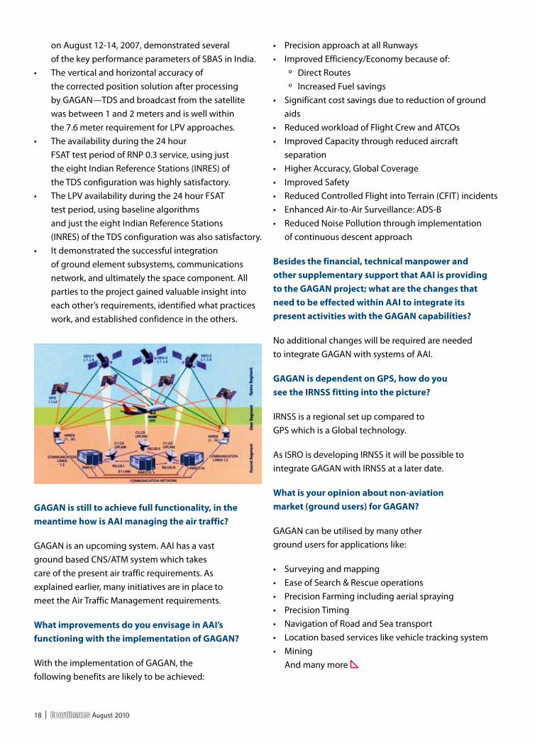
GAGAN has been taken up with an objective to implement the SBAS technology over the Indian region. This joint project by AAI and ISRO aims to provide a seamless navigation facility in the region, which is interoperable with other SBAS. Although primarily GAGAN is expected to provide satellite based navigation for civil aviation across South and East Asia, and will provide India with the most accurate, flexible and efficient air navigation system deployed meant for civil aviation, it will also be beneficial for other users. AAI’s efforts towards implementation of operational SBAS can be viewed as the first step towards introduction of modern CNS/ATM system over Indian airspace.
GAGAN will provide augmentation service for GPS over India, Bay of Bengal, South East Asia, and Middle East expanding upto Africa. The project involves establishment of a full complement of Satellite Based Augmentation System consisting of 15 Indian Reference Stations, 3 Indian Navigation Land Uplink Stations, 3 Indian Mission Control Centres, 3 Geo-stationary Navigation payload in C and L Bands and with all the associated software and communication links.
18 | August 2010
on August 12-14, 2007, demonstrated several ofthekeyperformanceparametersofSBASinIndia. • Theverticalandhorizontalaccuracyof the corrected position solution after processing byGAGAN—TDSandbroadcastfromthesatellite was between 1 and 2 meters and is well within the 7.6 meter requirement for LPV approaches. • Theavailabilityduringthe24hour FSATtestperiodofRNP0.3service,usingjust theeightIndianReferenceStations(INRES)of theTDSconfigurationwashighlysatisfactory. • TheLPVavailabilityduringthe24hourFSAT test period, using baseline algorithms and just the eight Indian Reference Stations (INRES)oftheTDSconfigurationwasalsosatisfactory. • Itdemonstratedthesuccessfulintegration of ground element subsystems, communications network,andultimatelythespacecomponent.All parties to the project gained valuable insight into each other’s requirements, identified what practices work,andestablishedconfidenceintheothers.
GAGAN is still to achieve full functionality, in the meantime how is AAI managing the air traffic?
GAGAN is an upcoming system. AAI has a vast groundbasedCNS/ATMsystemwhichtakescare of the present air traffic requirements. As explained earlier, many initiatives are in place to meet the Air Traffic Management requirements.
What improvements do you envisage in AAI’s functioning with the implementation of GAGAN?
With the implementation of GAGAN, the followingbenefitsarelikelytobeachieved:
• PrecisionapproachatallRunways • ImprovedEfficiency/Economybecauseof: º DirectRoutes º IncreasedFuelsavings • Significantcostsavingsduetoreductionofground aids • ReducedworkloadofFlightCrewandATCOs • ImprovedCapacitythroughreducedaircraft separation • HigherAccuracy,GlobalCoverage • ImprovedSafety • ReducedControlledFlightintoTerrain(CFIT)incidents • EnhancedAir-to-AirSurveillance:ADS-B • ReducedNoisePollutionthroughimplementation of continuous descent approach
Besides the financial, technical manpower and other supplementary support that AAI is providing to the GAGAN project; what are the changes that need to be effected within AAI to integrate its present activities with the GAGAN capabilities?
No additional changes will be required are needed to integrate GAGAN with systems of AAI.
GAGAN is dependent on GPS, how do you see the IRNSS fitting into the picture?
IRNSS is a regional set up compared to GPS which is a Global technology.
As ISRO is developing IRNSS it will be possible to integrate GAGAN with IRNSS at a later date.
What is your opinion about non-aviation market (ground users) for GAGAN?
GAGAN can be utilised by many other groundusersforapplicationslike:
• Surveyingandmapping • EaseofSearch&Rescueoperations • PrecisionFarmingincludingaerialspraying • PrecisionTiming • NavigationofRoadandSeatransport • Locationbasedserviceslikevehicletrackingsystem • Mining And many more

August 2010 | 19
20 | August 2010

August 2010 | 21

22 | August 2010

August 2010 | 23

24 | August 2010

August 2010 | 25

26 | August 2010

August 2010 | 27
GIS was first introduced in Malaysia about a decade ago. Amongst the
major issues that arose, was the absence or lack of digital geospatial data. GIS users then, needed to digitize their own data from hardcopy maps or survey plans to convert them to digital data. This conversion was certainly time-consuming and expensive, so much so, that accuracy of data was not of paramount importance. At present, with the realization of GIS as a tool capable of storing massive data, manipulating, displaying and querying, modeling, visualization applicable to multiple discipline, has lead to a rapid demand for GIS data and spatial data. The producers and suppliers of these data are no longer restricted to the Department of Survey and Mapping Malaysia as the government agency for mapping, but GIS users can now obtain digital geospatial data from other government agencies such as the Agriculture
Department, Local Government Authority, Department of Director-General of Lands and Mine as well as commercial data suppliers and geographic service providers. Consequently, the problems today are caused more by the increasing availability of digital geospatial data rather than the absence or lack of them.
Due to the scores of available data, users are in a dilemma as to which data to access and what is relevant to their needs. Very often, users are simply unaware of the types of data that are in existence and its location. To add to their predicament, with the numerous data providers, the users also have to choose from which acceptable or correct source to access and use, as data may be available from different sources. Disparate data from these sources, though could be integrated, are usually incompatible in terms of storage format, map projection, map scale, symbols, accuracy, and other cartographic specifications. These data therefore need to be evaluated and most often converted. Hence the question of merits of the data came into being.
Users’ perception of GIS data has been positive as they generally believe that it is accurate and reliable. The users of GIS data in Malaysia can be categorized into four broad groups, namely, the experts in GIS, the moderate users, the less expert users, and the non-expert users. The non expert users are often impressed by the beguiling attractiveness and the high aesthetic quality of cartographic products from GIS so much so the accuracy of data is not of much concern. This group of users usually use GIS to display graphics for reports. Although many use GIS, they however, seldom question the accuracy and reliability of this data. Matters such
polIcy
Adibah AwangGeo Law Research Group Faculty of Geoinformation Science and Engineering Universiti Teknologi Malaysia
shahidah Mohd AriffGeo Law Research Group Faculty of Geoinformation Science and Engineering Universiti Teknologi Malaysia
Ahmad Fauzi Bin nordinDeputy Director General of Survey and MappingDepartment of Survey and Mapping Malaysia
GEO-spatial data accuracy and its legal implicationsThe paper reflects on the law and standards pertaining to data accuracy and its legal implication due to the lack of accuracy by tracing the source or basis of data inaccuracy i.e. primary data source, processing of the data and the human factor.
Fig 1: uncertainty exist in every phase of the life cycle of geospatial data
28 | August 2010
as the map scale in use, the map projection adopted, and above all, the reliability of the base map from which the map is derived were not often broached. While not realizing these factors can affect their decisions, users interpret the information in GIS data according to whatever knowledge and experience they possessed. On the other hand, expert users such as the land surveyors, due to the nature of their profession, emphasis the need for the data to be precise, accurate, relevant and complete. GIS professionals that undergo formal education in GIS both locally and especially from abroad by now know the difference between GI System and GI Science. However many professionals from other disciplines still maintain GIS as a tool for decision making, although some may now know how to use GIS, to do prediction or to model their alternative solutions. Unfortunately these professionals have little or no knowledge of map making and surveying and hence fail to assess the quality of the data used. Moreover, their exposure to GIS is limited to short term training or courses on GIS which are inadequate in content. It can be summarized that Malaysians, except for professionals whose job requires the use of maps, are mostly not accustomed to map reading in their daily activities. Therefore it is understandable that users may not be aware of the accuracy of GIS data.
Geospatial data production
data life cycle
It is observed that changes that occur during the data life cycle (Figure 1) may affect data accuracy. As has been pointed out by Russell G, Congalton H, Todd Morer in their book Quantifying Spatial Uncertainty in Natural Resources : Theory & Application for GIS and Remote Sensing, (2000), common occurrence of changes of data in its life cycle are: during observation;
• during interpretation of observations, e.g. interpretation of vegetation boundaries on air photographs which creates linear entities;
• during digitization e.g. replacement
of a smooth, analogue line on a map with a polyline in GIS database
• during resampling associated with projection change or change of spatial resolution: generalization of data; &
• during assembly of results in support of decision or for archiving
In addition to the occurrence of changes during the data life cycle which may affect data quality, the following circumstances show instances when inaccuracy comes about. Geometric incompatibility occur when digital geospatial data captured from different map sheets or obtained from different sources fail to match. This may be due to changes to the geo-referencing standards in which new datum replaces old datum. These problems frequently occur during the transitional period when geospatial data referenced to original datum and new datum are in concurrent use.
Another instance where inaccuracy occurs is during the data collection stage where geospatial data is collected at different scales and with different map projections. National small-scale (1:750,000 and 1:500,000) and medium scale (1:50,000) maps were based on the cylindrical Rectified Skew Orthomorphic projection. On the other hand, large scale cadastral maps (1:5,000) is based on the rectangular grids of the Cassini Soldner projection. Data inaccuracy may also occur even when similar map projection and similar scale were used as the maps are produced by different agencies for different purposes at different times. It requires reconciliation of mismatching features across map boundaries which is clearly not a trivial task requiring human decisions to apply logic to resolve the problem. Another common phenomenon that causes data inaccuracy is the quality degradation due to time. Although data collection and digitizing are carried out using relatively stringent specifications as a rule, the same level of requirements is not always enforced when digital databases are updated. This has resulted in the degradation of geometric accuracy in the contents of the database. It also tends to invalidate the
data quality information attached to the metadata of the data sets concerned.
Quality is also degraded when digital databases are not maintained properly. Ideally, a geo-database is a faithful snapshot of the status of human activities and natural features that are found at a particular geographic area of interest at a specific point in time. When these features or activities change, the database must also be updated accordingly. This requires continuous monitoring of human activities and the natural environment in order to check all the changes that have occurred. When such database is not updated, it will lead to serious uncertainties when data is used for time-sensitive spatial problem solving.
data producers/ providers
In Malaysia, geospatial data producers could be conveniently categorized into two, i.e. government and private sector data producers. Most, if not all of these producers rely on the Department of Survey & Mapping, Malaysia’s (widely known by its Malay acronym JUPEM) cadastral parcel fabric or topographic data as the base data to collect and produce their own geospatial information. At national level, a committee known as the National Malaysian Spatial Data Committee (formerly called the National Mapping Committee) was formed to coordinate the data acquisition activities of these government geospatial data producers.
Related issues of data acquisition and production, including addressing the needs of members and data quality were worked upon by the various sub-committees formed under it. The activities of geospatial data producers in the private sector were however left uncoordinated and not very much controlled except for the conduct of cadastral surveys and production of cadastral survey data. Information on their activities are only known in two circumstances, i.e. when application is made to JUPEM to collect data and when those acquired data were submitted to JUPEM to obtain clearance for geospatial information production. Unlike in the case of cadastral data,
August 2010 | 29
vetting of other geospatial data by JUPEM only involves the filtering of security sensitive information, and not quality or more specifically accuracy inspection.
JUPEM remains inarguably the major producer and provider of geospatial data in Malaysia. It retains ownership over those data in the form of copyright over its product. Nevertheless, data ownership has brought about issues of legal liability founded on the “harm-based concept” in which harm or injury incurred as a result of errors or shortcomings or incorrect decision could well be due to data inaccuracy. In such instances, in determining the liability of parties involved in the handling of geographic information, i.e. from the original data providers/producers, software producers, secondary producers and finally the users, the law will look at those in the information chain and consider whether they have exercised appropriate standard of duty to prevent the occurrence of the damages. The law that is applicable to ascertain liability is the law of contract and tort. However, there is no specific legislation on the matter. JUPEM had in the past provided disclaimers exempting them from liability, on its printed maps and recently, on its
digital map products; however, other government agencies had varied practices pertaining to this matter. Although there has not been any known litigation against them, all currently acknowledged the fact that users are getting more sophisticated and increasingly aware of their rights and as such many had taken steps to protect themselves in the eventuality of providing inaccurate data to their clients.
However, the liability in geospatial products and services relating to computerized geographic information systems is difficult to determine by traditional legal theory. This is because of the wide array of current as well as potential application of geographic information technologies. Each application requires integration of information specific to the application and often will involve different attributes, analytical method, spatial features and accuracy requirements.Other legal issues that have to be tackled by JUPEM and other data providers should include identifying duties which are mandatory as data providers regarding the quality of data; duties that every professional is expected to do (Bedard, Devillers, Gervais & Jean-soulin, 2004).
Among these duties are the responsibilities of informing users about the datasets, that not only provide users with information pertaining to the content of the data but the limitation or defect or potential risk in the data utilization. In other words, the data producers need also consider users’ intended usage of the data and warn them accordingly. These legal obligations or ethical requisites may be provided under the code of conduct as provided by the Licensed Land Surveyors Act 1958 (Revised 1991) or the consumer protection legislations.
data accuracy
The standards of data accuracy vary from one producer to the other, and may be very significantly different due to the fact that their production serves differing purposes. In the case of JUPEM, their town and city maps are produced at scales ranging from 1:1,250 to 1:10,000; the planimetric accuracy of these maps range respectively from 0.6m to 5.0m. Additionally, topographic maps are produced at scales of 1: 25,000 and 1: 50,000 and their planimetric accuracies are 12.5m and 25.0m respectively. On the other

30 | August 2010
hand, the height accuracies would be at half the contour intervals depicted on those maps.
Another source of geospatial data produced by JUPEM is the cadastral survey database. The database was originally developed through the keying-in of bearing and distance values appearing on certified plans, which were derived from actual ground surveys. These cadastral surveys vary in accuracies as they were performed previously under three different categories or classes, according to the needs of meeting the required level of accuracies; for instance surveys in town areas would need to achieve higher than 10cm level of accuracy, whereas in the countryside accuracy of 50cm is considered adequate. Currently, geospatial data produced from the conduct of cadastral surveys evidently were the most accurate and as such were relied upon to serve as base data for geospatial data production by others. With the most dependable accuracy attribute, it also served as one of the core datasets of the nation’s spatial data infrastructure.
Beginning 2006, the development of the National Utility Database was started by JUPEM, whereby data on the location of underground utilities such as gas, water and sewage pipelines as well as telecommunication and electric cables were captured and stored in the said database. Those data were initially sourced from the utility providers and due to the differing reliability of the information provided, they had to be segregated into four quality levels, i.e. Quality Levels (QL) A to D, with QL A being the highest level in terms of accuracy, with ±10 cm planimetric and height (depth) accuracies.
Other governmental producers of geospatial data such as the Departments of Agriculture, Mineral and Geoscience, Planning, Forestry etc., have their own accuracy criteria to meet their needs and specifications but is clearly not as demanding as that of JUPEM.
Apparently, the need for high accuracy geospatial data is most evident in the case of underground utility data production and use. It would be obvious that erroneous data can lead to erratic digging in the course of emplacing new facilities and this could further cause accidents resulting in extensive damages, including the loss of
lives. The need for highly accurate cadastral surveys too has been recognized as being imperative and given a lot of emphasis in the past. As such, concerned surveys have been traditionally very tightly regulated and this has resulted in a reliable cadastral survey system that underpins the highly progressive land market of Malaysia.
Geospatial data accuracy specifications or statements were in the past not given much attention. Nevertheless, over the last decade or so, demands have been made by users for data producers to publish quality or at least accuracy statements for their data. JUPEM has responded to this call by publishing data accuracy statements in the metadata published through their on-line JUPEM Geoportal (a dedicated departmental website to provide on-line sales of data and services to users).
Efforts to standardize the measure of data quality (including data accuracy) and publishing them had been initiated over the last few years. JUPEM has taken the lead in this effort, whereby the task of determining data quality through field measurements and verification had been conducted for the map sheets that they had produced. This form of verification, albeit laborious, is deemed necessary and the outcome of this quality check is published in the metadata produced by the department. JUPEM had also been engaged in developing the data quality standards which would eventually be utilized by all geospatial data producers.
legal implication from data inaccuracy
Malaysian is a non-litigious society. There is no known legal suit pertaining to injuries or damages arising from data inaccuracy. However, court cases with regard to damages suffered as a result of data inaccuracy, in developed countries where GIS originated are on the rise. Issues of liability as a result of loss of earnings, opportunities, property and even life gave rise to questions of ownership or authorship which have become more uncertain as data can be easily manipulated and mixed with data from other sources, sometimes of unknown lineage and perhaps at inappropriate scale. Liability
has been shown to possibly arise from inaccurate, incomplete and misleading information of data as well as incorrect decisions. The first indications that there are serious problems with the data are when accidents take place (Cho, 2005).
It has to be noted that on the international front, Malaysia had on two occasions appeared in the International Court of Justice in disputes with her neighbors, Indonesia, over the islands of Ligitan and Sipadan, and with Singapore, over Pedra Branca. Amongst a multitude of factors put forth in the arguments, aspect of data inaccuracies was also hinged upon in both of the aforementioned cases.
Since there are no court cases from Malaysia to illustrate the damages or injury that occur owing to data inaccuracy, the following cases from USA and Australia are referred to indicate the legal implication as a result of error in maps, that can be fatal:
case 1
According to a report in the US journal Point of Beginning as cited by the Asian Surveying and Mapping (11 March 2009), mistakes by surveyors in Texas are being blamed for millions of dollar losses suffered by local landholders as a result of flooding in the aftermath of Hurricane Ike, the third most destructive hurricane in the USA. Some of the damage in the US was due to flooding, where housing had been built below the Base Flood Level. This is a contour defined by the Federal Emergency Management Agency to correspond to a 100 year flood level. The position of the Base Flood Level was fixed by the National Geodetic Survey long ago and marked by concrete and brass monuments. In the 1980’s the Federal Emergency Management Agency (FEMA) re-measured the contour and found that the flood plain was about a meter above the old marks. It issued a new map that become the document of reference for insurance companies and other authorities. However, the surveyors continued to rely on the old elevations. As a result of the mistake made by the surveyors, 20 homes near the town of LaBelle were built in the flood plain as people who thought their new homes

August 2010 | 31
were being built above flood level were actually building a meter below it. To add to the homeowners’ nightmare, they had no flood insurance and FEMA would not permit them to rebuild their homes because they were in the flood plain.
case 2
Four New South Wales, National Parks & Wildlife Service (NPWS) officers were killed from smoke suffocation in a burn-off operation. The officers were given maps that showed two possible escape routes, but which ended in impenetrable bush or line of cliffs. The Senior Deputy State Coroner informed the court that there were deficiencies in the maps used in the operations as information contained in the map issued by NPWS showed a cleared hilltop, which potentially could have provided shelter from the fire. Unfortunately, the map did not show a 30m cliff which stood between anyone trying to escape the fire and the cleared area. The map also showed a path known as Wallaby Track running directly towards a local motorway. In reality this path twists into impenetrable bush. It was found by the court that the original botanical map had not been ground-truthed to include specific details and did not mark areas with safe refuges to retreat to as required in the fire management procedures guidelines (Cho, 2005).
The above two cases demonstrate the classic issues of standards to be attained if liability is to be avoided. The duty to take care, the responsibility of due diligence to those who may be affected by a lack of care, the reliance on information to one’s detriment, and the subsequent injury, damage and loss that occurs, are established legal standards. Such standards are set either by statutory mandates or through the common law. In Malaysia, however, there’s no statutory mandate in order to ensure compliance. However, the common law of tort may be applicable in failure to meet the required standard of care by the profession.
conclusion
The rapid growth of GIS users in Malaysia
has raised the need for data accuracy and the appropriate management of these data. There is no specific law concerning data quality, and no consistent legal framework on the management of GIS or geospatial data; what exists is simply a patchwork of self regulation in the form of government circulars and statutes. It is thus important that Malaysia have a codified policy on managing geospatial data as the country moves towards a spatially enabled government. This will enable relevant bodies to be given statutory mandate to ensure effective and up to date collection of data and the imposition of standards to be followed by data producers so as to ensure data quality. It is also important for the government and institutions of higher learning to give adequate emphasis in formulating appropriate programs to create awareness on the importance of data accuracy.
References
Abdulharis, R., B.van Loenen & J.Zevenbergen,(2005),
“Legal Aspects of Access to Geo-Information within
Indonesian Spatial Data Infrastructure” in ISPRS Workshop
on Service & Application of Spatial Data Infrastructure,
XXXVI, Oct. 14-16, 2005, Hangzhou, China at pp.147-153
Bishr, M., Wytzisk, A., Morales, J., (2007) “GeoDRM:
Towards Digital Management of Intellectual Property
Rights for Spatial Data Infrastructures” in Research
and Theory in Advancing Spatial Data Infrastructure
Concepts, ed. Onsrud, H, Redlands, CA: ESRI Press
Bedard, Y, Devillers, R, Gervais, M, & Jean-soulin,
(2004) “Towards Multidemensional User Manuals for
Geospatial Datasets: Legal Issues and their consideration
into the Design of a Technological Solution” of the
Third International Symposium on Spatial Data Quality
(ISSDQ’04), 15 -17 April Bruck an der Leitha, Austria
Blackmore. M and Longhorn R. (2004) “Ethics & GIS: The
Practitioner’s Dilemma”, in AGI 2004 Conference Workshop
on “GIS ethics”, 14 October 2004 London, England, UK
Cho, G., (1998), Geographic Information Systems
& the Law Mapping the legal frontiers, John
Wiley & Sons Ltd, West Sussex, England.
Cho, G., (2005), Geographic Information Science Mastering
the Legal Issues (2005),John Wiley & Sons Ltd. England.
Cho, G, (2007) “National Spatial Data Infrastructure,
intellectual property rights and geospatial technologies
in aiding economic growth” in 6th Annual International
Conference and Exhibition on Geographical Information
Technology and Applications, Kuala Lumpur, Malaysia.
Mohamed, A.M., (1998), Case Studies of NSDIs in
countries in transition – Malaysia, October 1998 as
assessed via internet on 8 February 2008 in http://
gsdidocs.org/docs1998/canberra/malaysia.html
Mark R. Leipnik, Donald P. Albert, GIS
in Law Enforcement, 2002
Nordin, A.F., (2007), “Spatially Enabled Government
: The Malaysian Case” in the International Workshop
on Spatial Enablement of Government and NSDI-
Policy Implications”, 12 Jun 2007, Seoul, Korea.
Onsrud, H.J. (2004), Geographic Information Legal
Issues, in Encyclopedia of Life Support System
(EOLSS), Developed under the auspices of the
UNESCO, EOLSS Publishers, Oxford, UK
Onsrud, H.J. (1999), “Liability in the use of GIS &
Geographical Datasets” in Longley, P., Goodchild,
M, Maguire, D and Rhind, D (eds.), Geographical
Information Systems :vol 2 Management Issues and
Applications, John Wiley & sons, pp 643-652
Onsrud, Adler, Archer, Licensing Geographic
Data & Services, 2004 National Academies
Saxby, S. Dr. , “Public Policy and the
Development of a UK National Geographic
Information Strategy”, 2006,International
Journal of Law and Information Technology Vol.
14 No. 2 Oxford University Press
Gehan Gunasekara, The ‘final’ privacy frontier? Regulating
trans-border data flows, 2006,International Journal of Law
and Information Technology International Journal of Law and
Information Technology Vol. 15 No. 3 Oxford University Press
Jane Holder, Carolyn Harrison, Law and Geography,
2003, Oxford University Press, London
Ida Madieha Azmi, “Personal Data Protection : The
Malaysian Experience”, in Information & Communications
Technology Law, June 2007, Vol.16, Issue 2 pp. 125-135
as assessed on 20 August 2009 from http://web.ebscohost.
com/ehost/delivery?vid=25&hid=0a4335b1-57de-4fal
This was an invited paper at the Eighteenth United
Nation Regional Cartographic Conference for Asia
and the Pacific , Bangkok, 26-30 October 2009.
32 | August 2010
India’s Polar Satellite Launch Vehicle (PSLV-C15) successfully
launched CARTOSAT-2B from Satish Dhawan Space Centre (SDSC) SHAR, Sriharikota on 12 July 2010.
In addition to CARTOSAT-2B; PSLV-C15 carried four auxiliary satellites namely STUDSAT a pico-satellite weighing less than 1 kg, built jointly by students from a consortium of seven engineering colleges form Karnataka and Andhra Pradesh, India; two nano satellites NLS 6.1 and NLS 6.2 from University of Toronto, Canada; and ALSAT-2A, a micro-satellite from Algerian Space Agency.
cARtosAt-2B
The 694 kg CARTOSAT-2B is the seventeenth remote sensing satellite of India. Data from the satellite will find applications in cartography at cadastral level, urban and rural infrastructure development and management, as well as Land Information System (LIS) and Geographical Information System (GIS).
CARTOSAT-2B carries a state-of-the-art panchromatic camera (PAN) whose imagery will have a spatial resolution of 0.8 meter. The camera has a swath of 9.6 km. The highly agile CARTOSAT-2B is steerable up to ± 26 degrees
along as well as across the direction of its movement to facilitate imaging of any area more frequently. The satellite also carries a Solid State Recorder with a capacity of 64 Giga Bits to store the images taken by its camera.
The satellite’s health will be continuously monitored from the Spacecraft Control Centre at Bangalore with the help of ISTRAC network of ground stations at Bangalore, Lucknow, Mauritius, Biak in Indonesia, Svalbard in Norway and Troll in Antarctica.
The initial phase of operation of the satellite has been successfully completed.
The camera has been switched on, and images of high quality are being received. http://www.isro.org/pressrelease/scripts/pressreleasein.aspx?Jul21_2010
studsAt
STUDSAT (Student Satellite) is a unique satellite technology endeavor undertaken by under-graduate students from seven different Academic Institutions in India under the guidance of the Indian Space Research Organization (ISRO). STUDSAT is the first Pico-Satellite being launched by India.
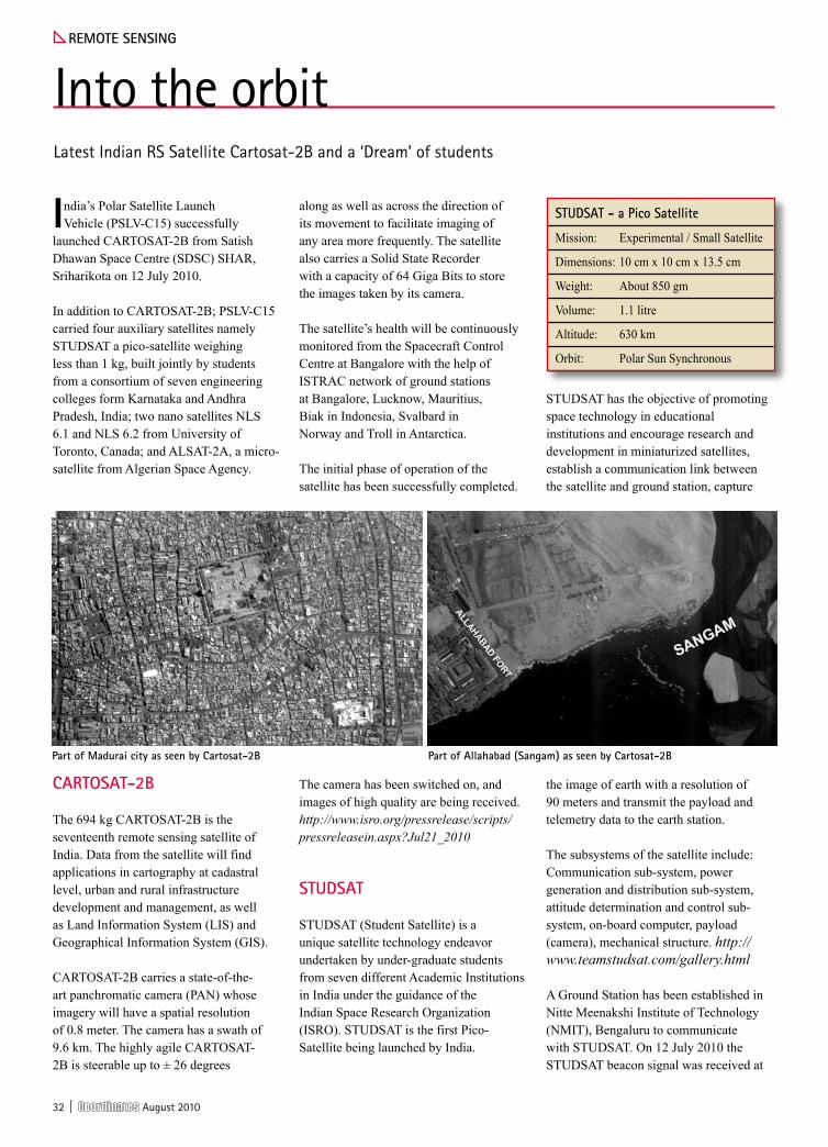
STUDSAT has the objective of promoting space technology in educational institutions and encourage research and development in miniaturized satellites, establish a communication link between the satellite and ground station, capture
the image of earth with a resolution of 90 meters and transmit the payload and telemetry data to the earth station.
The subsystems of the satellite include: Communication sub-system, power generation and distribution sub-system, attitude determination and control sub-system, on-board computer, payload (camera), mechanical structure. http://www.teamstudsat.com/gallery.html
A Ground Station has been established in Nitte Meenakshi Institute of Technology (NMIT), Bengaluru to communicate with STUDSAT. On 12 July 2010 the STUDSAT beacon signal was received at
ReMote sensInG
Into the orbitLatest Indian RS Satellite Cartosat-2B and a ‘Dream’ of students
studsAt - a pico satellite
Mission: Experimental / Small Satellite
Dimensions: 10 cm x 10 cm x 13.5 cm
Weight: About 850 gm
Volume: 1.1 litre
Altitude: 630 km
Orbit: Polar Sun Synchronous
part of Allahabad (sangam) as seen by cartosat-2Bpart of Madurai city as seen by cartosat-2B

August 2010 | 33
the tracking station in NMIT. It was also heard by HAMs all over Bangalore. On 15 July 2010 NASTRAC received the Telemetry Data with packets separated and confirmed the satellite is in mission mode. The satellite has thus completed the beacon mode of communication and has entered the mission mode, where in it will transmit encrypted data at 437.505 MHz. Based on material available at: www.isro.org and www.teamstudsat.com
Where there is a will…there is a way!
The idea for the STUDSAT project
crystallized during the International
Astronautical Congress, 2007,
between four students from
different academic institutions,
from Hyderabad and Bengaluru,
after their epochal interaction
with the Project Director of Small
Satellites, ISRO Satellite Centre.
The initial student team completed
the conceptual design of the
satellite. They then approached
their institutions to persuade
them to contribute funds for the
realization of the ambitious project.
The institutions wholeheartedly
supported the team.
The team and institutions then
approached ISRO for a Preliminary
Review of the Student Satellite
project. After a detailed review, ISRO
approved the project. Subsequently,
the team grew to around 45
students from ten different
academic institutions. Of the ten
participant colleges, seven formed a
consortium in order to sponsor the
project. An internal MoU was signed
between the colleges, and they
chose Nitte Meenakshi Institute
of Technology, Bengaluru as their
representative to sign the official
MoU with ISRO on their behalf.
What are the added features in CARTOSAT-2B as
compared to CARTOSAT-2A? What will be its marketing strategy?
CARTOSAT-2B is an identical satellite of CARTOSAT-2A and is meant for continuity of services. They are not available for commercial distribution. As of now it is only available for use of government of India.
China has also launched a Remote Sensing satellite recently and is planning to launch a high resolution mapping satellite in 2011. Do you think the competition is going to get tougher or the market is big enough for all?
There are many developments happening and resolution of satellites is improving. It is the trend of the day and even many developing nations are coming up with small and micro satellites. As the satellites are increasing the technology is developing, the demand is increasing so are the applications. So, though competitors are increasing, the market is also expanding and there is space for everybody to play.
Our strategy was never to directly compete with anyone in the international market since these satellites are not purely commercial in nature. Our strategy is to meet all our domestic needs with our own satellites and sell the spare capacity to international users.
We hope to continue to play a lead role with our large constellation of satellites, with more satellites in the discussion or planning phases. We welcome more providers coming in and more satellites being available.
One advantage that Antrix has vis-à-vis its product portfolio when compared to other such service providers globally?
The uniqueness of the product portfolio is the diversity of the data and continuity of the data services. Data availability is assured even for long term projects. Also it is the largest constellation and also cost effective. The data provided is technologically equal and the dollars paid per imagery are relatively lower.
What is your concern about the remote sensing market in the days to come?
There is no concern about the technology or the satellites. But there is a concern about the turn around time and about meeting the customers’ demands in a timely manner. There is a gap between the expectations and availability. So we have to address issues of better delivery mechanism, faster turn around time and better technology. Earlier users asked for stereo data, then high resolution, now they want multi-spectral high resolution and multi-spectral stereo, so the needs are expanding. Our strategy is to provide best services meeting the user demand.
“Our strategy is to provide best services meeting the user demand” says shri KR sridhara Murthi, Managing director, Antrix corporation with reference to the Indian Remote sensing satellite.
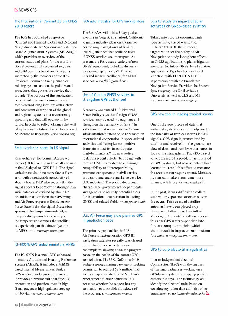
34 | August 2010
neWs Gps
the International committee on Gnss 2010 report
The ICG has published a report on “Current and Planned Global and Regional Navigation Satellite Systems and Satellite-Based Augmentation Systems (SBASes),” which provides an overview of the current status and plans for the world’s GNSS systems and associated regional and SBASes. It is based on the reports submitted by the members of the ICG Providers’ Forum on their planned or existing systems and on the policies and procedures that govern the service they provide. The purpose of this publication is to provide the user community and receiver-producing industry with a clear and consistent description of the global and regional systems that are currently operating and that will operate in the future. In order to reflect changes that will take place in the future, the publication will be updated as necessary. www.unoosa.org
small variance noted in l5 signal
Researchers at the German Aerospace Center (DLR) have found a small variance in the L5 signal on GPS IIF-1. The signal variation results in no more than a 5-cm error with a predictable periodicity of about 6 hours. DLR also reports that the signal appears to be “hot” or stronger than anticipated or advertised by about 1/2 db. Initial reaction from the GPS Wing and Air Force experts at Schriever Air Force Base is that the signal fluctuation appears to be temperature-related, as the periodicity correlates directly to the temperature extremes the satellite is experiencing at this time of year in its MEO orbit. www.ngs.noaa.gov
IG-500n: Gps aided miniature AhRs
The IG-500N is a small GPS enhanced miniature Attitude and Heading Reference System (AHRS). It includes a MEMS based Inertial Measurement Unit, a GPS receiver and a pressure sensor. It provides a precise and drift-free 3D orientation and position, even in high G maneuvers at high updates rates, up to 100 Hz. www.sbg-systems.com
FAA asks industry for Gps backup ideas
The US FAA will hold a 3-day public meeting in August, in Stanford, California to gather industry ideas on alternative positioning, navigation and timing (APNT) methods that could be used if GNSS services are interrupted. At present, the FAA uses a variety of non-GNSS equipment, including distance measuring equipment, VHF radio, ILS and radar surveillance, for APNT services. www.flightglobal.com
use of foreign Gnss services to strengthen Gps authorized
A recently announced U.S. National Space Policy says that foreign GNSS services may be used “to augment and strengthen the resiliency of GPS.” In a document that underlines the Obama administration’s intention to rely more on international cooperation in space-related activities and “energize competitive domestic industries to participate in global markets,” the new policy reaffirms recent efforts “to engage with foreign GNSS providers to encourage compatibility and interoperability, promote transparency in civil service provision, and enable market access for U.S. industry.” The policy document charges U.S. governmental departments and agencies to identify potential areas for international cooperation including GNSS and related fields. www.grace.ac.uk
u.s. Air Force may slow planned Gps III production pace
The primary payload for the U.S. Air Force’s next-generation GPS III navigation satellites recently was cleared for production even as the service contemplates slowing down the program based on the health of the current GPS constellation. The U.S. DoD, in a 2010 budget reprogramming package, is seeking permission to redirect $2.7 million that had been appropriated for GPS III parts procurement to other activities. It is not clear whether the request has any connection to a possible slowdown of the program. www.spacenews.com
egis to study on impact of solar activities on Gnss-based aviation
Taking into account upcoming high solar activity, a need was felt for EUROCONTROL the European Organization for the Safety of Air Navigation to study ionosphere effects on GNSS applications to plan mitigation measures for future GNSS-based aviation applications. Egis has been awarded a contract with EUROCONTROL in partnership with the French Air Navigation Service Provider, the French Space Agency, the Civil Aviation University as well as CLS and M3 Systems companies. www.egis.fr
Gps new tool in reading tropical storms
One of the new pieces of data that meteorologists are using to help predict the intensity of tropical storms is GPS signals. GPS signals, transmitted by satellite and received on the ground, are slowed down and bent by water vapor in the earth’s atmosphere. The effect used to be considered a problem, as it related to GPS systems, but now scientists have learned to “read” this effect to measure the area’s water vapor content. Moisture rich air can make a hurricane more intense, while dry air can weaken it.
In the past, it was difficult to collect such water vapor measurements over the ocean. Frisbee-sized satellite antennas have been placed atop stationary platforms in the Gulf of Mexico, and scientists will incorporate this new GPS water vapor data into forecast computer models, which should result in improvements in storm forecasts. www.spokesman.com
Gps to curb electoral irregularities
Interim Independent electoral Commission (IIEC) with the support of strategic partners is working on a GPS-based system for mapping polling centers in Kenya. The technology will identify the electoral units based on constituency rather than administrative boundaries www.standardmedia.co.ke

August 2010 | 35
neWs lBs
GIsRoam brings GIs to the ipAd
Cogent3D GISRoamT is a new iPad and iPhone application that allows the user to load, view, collect, search, edit and save ESRI GIS Shapefiles. It includes searching, feature attribution editing, and GPS enhanced creation of new Polygon, Line, and Point features in new or existing Shapefile layers while you roam. www.Cogent3D.com
sybase sQl Anywhere 12
Sybase has released its SQL Anywhere 12 database and synchronization solution. It is optimized for mission-critical database applications running outside traditional data center environments requiring little or no onsite IT support. Its enhancements include support for storage and synchronization of spatial data, iPhone devices and large-scale synchronization environments; and new self-management features. www.sybase.com
space expertise helps expo visitors
Insiteo supported by ESA’s Business Incubation Centre has developed a new mobile phone indoor navigation system, which will soon help the six million annual visitors find their way around at the largest exhibition centre in Paris. This navigation system is effective for large inside spaces such as exhibition grounds, because the vast, complicated layouts of such tradeshows can be confusing. www.insiteo.com
tomtom extends global coverage
TomToms latest digital map products, including Tele Atlas MultiNet 2010.06 now cover more than 32 million km across 102 countries and territories globally. The map database is constantly validated by millions of drivers who use it in GPS devices, smartphone applications and online. Nearly half a million edits were sourced from community input in the latest release. www.tomtom.com
Magellan launches next Gen of eXplorist
Magellan’s new eXplorist 510, 610 and 710 devices allow adventurers to navigate to outdoor destinations worldwide, capture geotagged photos along the way, and share their experiences online when they return home. All three new eXplorist handheld GPS units come equipped with a camera, microphone, and speaker. www.magellangps.com
Map oil spill with mobile app
Trimble has launched Map the Spill, a free mobile app and website that empowers Gulf Coast residents and the public to report on the oil spill. It allows those directly and indirectly impacted by the spill to capture and chronicle what they see happening to the land, sea and wildlife in their areas. www.trimble.com
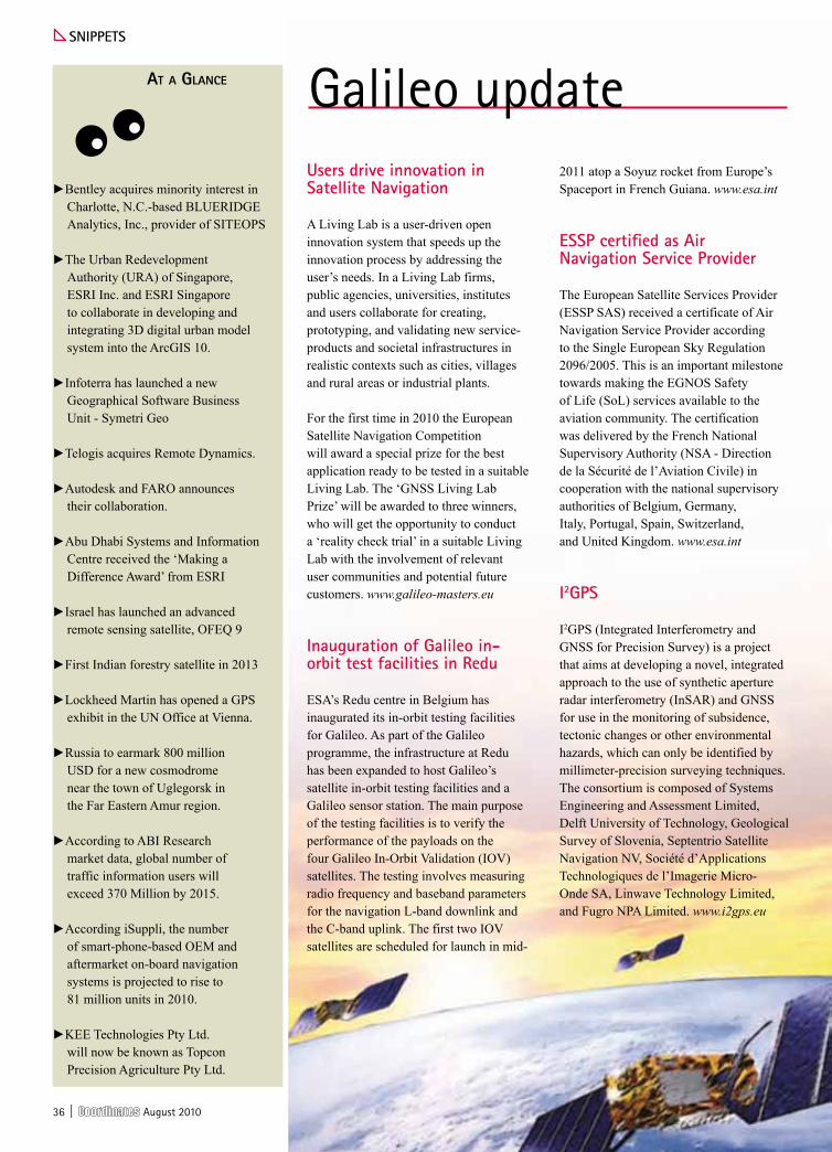
36 | August 2010
At A GlAnce
►Bentley acquires minority interest in Charlotte, N.C.-based BLUERIDGE Analytics, Inc., provider of SITEOPS
►The Urban Redevelopment Authority (URA) of Singapore, ESRI Inc. and ESRI Singapore to collaborate in developing and integrating 3D digital urban model system into the ArcGIS 10.
►Infoterra has launched a new Geographical Software Business Unit - Symetri Geo
►Telogis acquires Remote Dynamics.
►Autodesk and FARO announces their collaboration.
►Abu Dhabi Systems and Information Centre received the ‘Making a Difference Award’ from ESRI
►Israel has launched an advanced remote sensing satellite, OFEQ 9
►First Indian forestry satellite in 2013
►Lockheed Martin has opened a GPS exhibit in the UN Office at Vienna.
►Russia to earmark 800 million USD for a new cosmodrome near the town of Uglegorsk in the Far Eastern Amur region.
►According to ABI Research market data, global number of traffic information users will exceed 370 Million by 2015.
►According iSuppli, the number of smart-phone-based OEM and aftermarket on-board navigation systems is projected to rise to 81 million units in 2010.
►KEE Technologies Pty Ltd. will now be known as Topcon Precision Agriculture Pty Ltd.
snIppets
users drive innovation in satellite navigation
A Living Lab is a user-driven open innovation system that speeds up the innovation process by addressing the user’s needs. In a Living Lab firms, public agencies, universities, institutes and users collaborate for creating, prototyping, and validating new service-products and societal infrastructures in realistic contexts such as cities, villages and rural areas or industrial plants.
For the first time in 2010 the European Satellite Navigation Competition will award a special prize for the best application ready to be tested in a suitable Living Lab. The ‘GNSS Living Lab Prize’ will be awarded to three winners, who will get the opportunity to conduct a ‘reality check trial’ in a suitable Living Lab with the involvement of relevant user communities and potential future customers. www.galileo-masters.eu
Inauguration of Galileo in-orbit test facilities in Redu
ESA’s Redu centre in Belgium has inaugurated its in-orbit testing facilities for Galileo. As part of the Galileo programme, the infrastructure at Redu has been expanded to host Galileo’s satellite in-orbit testing facilities and a Galileo sensor station. The main purpose of the testing facilities is to verify the performance of the payloads on the four Galileo In-Orbit Validation (IOV) satellites. The testing involves measuring radio frequency and baseband parameters for the navigation L-band downlink and the C-band uplink. The first two IOV satellites are scheduled for launch in mid-
2011 atop a Soyuz rocket from Europe’s Spaceport in French Guiana. www.esa.int
essp certified as Air navigation service provider
The European Satellite Services Provider (ESSP SAS) received a certificate of Air Navigation Service Provider according to the Single European Sky Regulation 2096/2005. This is an important milestone towards making the EGNOS Safety of Life (SoL) services available to the aviation community. The certification was delivered by the French National Supervisory Authority (NSA - Direction de la Sécurité de l’Aviation Civile) in cooperation with the national supervisory authorities of Belgium, Germany, Italy, Portugal, Spain, Switzerland, and United Kingdom. www.esa.int
I2Gps
I2GPS (Integrated Interferometry and GNSS for Precision Survey) is a project that aims at developing a novel, integrated approach to the use of synthetic aperture radar interferometry (InSAR) and GNSS for use in the monitoring of subsidence, tectonic changes or other environmental hazards, which can only be identified by millimeter-precision surveying techniques. The consortium is composed of Systems Engineering and Assessment Limited, Delft University of Technology, Geological Survey of Slovenia, Septentrio Satellite Navigation NV, Société d’Applications Technologiques de l’Imagerie Micro-Onde SA, Linwave Technology Limited, and Fugro NPA Limited. www.i2gps.eu
Galileo update

August 2010 | 37
STS-750R seriesCSD card date storage(maximum 2G)
Mini USB port for communication
Built-in laser plummet (optional)
Dual axis compensation
Onboard programs upgraded
300m reflectorless
SUPERTECH SALES AND SERVICES Add: T 9, 3rd Floor Shree Krishna Complex Sharma Market Sector 5 NOIDA 201301 (U.P)Phone: 0120 2425491 Mob: 9810788846, 9810703308 Email: [email protected]
USB cable transfer SD card Function and USB interface Larser Plummet
Always keep moving forward,
upgrading version STS-750R
series will come soon

38 | August 2010
neWs ReMote sensInG
digitalGlobe: high-resolution imagery for handheld Gps, releases ortho product series
DigitalGlobe is to provide high-resolution imagery for DeLorme’s Earthmate series, including the PN-30, PN-40 and PN-60 models. Hikers, climbers and other outdoor enthusiasts will be able to update their GPS device with accurate imagery. Its Ortho Vision line is designed for professional users in need of quality images for analysis and identification. Images classified as Ortho Vision Premium will feature less than 3% cloud cover; geometric breaks less than one meter and tonally balanced imagery in addition to no haze, pollution or fog. www.digitalglobe.com
Food grain output in India seems stagnant for 10 years
A nine-member team of scientists from NASA, the Boston University and the Indian Institute of Tropical Meteorology, Pune, analyzed the satellite remote sensing data from 1982-2006 and has confirmed that the growth rate of food grain production in India has been stagnant in the last decade. http://economictimes.indiatimes.com
Remote sensing Applications (e-Book)
National Remote Sensing Center, India has brought out a book on “Remote Sensing Applications” covering land, water, atmosphere and natural disasters. The book has been compiled and edited by P.S. Roy, R.S Dwivedi and D. Vijayan. The book can be viewed/downloaded at www.nrsc.gov.in/Remote.html
topcon's Ip-s2 hd Mapping system
Topcon Positioning Systems has released the IP-S2 HD Mapping System – a vehicle-mounted surveying and mapping system featuring a high-definition LiDAR scanner. It includes high-precision GNSS receivers, IMU, vehicle wheel encoder, 360-degree digital cameras and Velodyne’s HDL-64E S2.2 LiDAR scanner. www.topconpositioning.com
Water resources conservation in china using eRdAs IMAGIne
The Ministry of Water Resources, China recently announced a project that uses ERDAS IMAGINE to facilitate conserving and protecting China’s water resources. It is being used to identify the areas where the water is being adversely affected by soil erosion. www.erdas.com
FARo introduces break resistant sMR
FARO Technologies announced the release of its break resistant spherically mounted retroreflector as a part of their newly expanded line of laser tracker targets. These new targets are available in three models: standard accuracy, long range, and high performance. www.faro.com
Global Forest Monitoring service
DMCii’s Global Forest Monitoring service uses satellite imagery to produce easily-understood maps of forest cover change. The service’s wide-area forest surveys can be updated annually, monthly - or more often still for areas judged most at risk – delivering the timely data necessary for operational management. It is based around a constellation of six satellites known as the Disaster Monitoring Constellation which work together to provide rapid mapping services. www.dmcii.com
cooperation to promote satellite technology application
JAXA, Japan and the ADB has agreed to cooperate in providing technical assistance to ADB supported projects using satellite data and will work on capacity development on the use of satellite data through the training of persons from national institutions in Asia and the Pacific region. www.jaxa.jp
Image analysis toolbox for esRI® ArcGIs® platform
ITT Corporation announced the third phase of its software technology with
the ArcGIS. Building on the multi-year integration of the two platforms, this latest phase will give ArcGIS users the ability to access ENVI tools for analyzing geospatial imagery directly from within the ArcGIS desktop and server environments. www.itt.com
dAlsA announces expanded capabilities
DALSA announced expanded capabilities including backside illumination (BSI) in custom image sensors for aerospace applications in earth observation and remote sensing. New technologies in multispectral filters allow DALSA to capture images from not only the traditional RGB visible color bands but also a number of near-infrared bands in a single compact and cost effective package. The new custom back side thinning capability enables the high quantum efficiency. www.dalsa.com
African observatories will gather biodiversity data
Scientists are pooling remote-sensing satellite data and GIS services for two pan-African digital observatories that will provide accurate and readily accessible information on biodiversity and forest cover for policymakers. Under a grant the European Commission’s Joint Research Centre is supporting the development of the observatories. One is the Observatory for the Forests of Central Africa; the other is the Digital Observatory for Protected Areas. http://allafrica.com
Inventory of Russian forest using space technologies
Satellite imagery based on the State Forest Inventory Program on behalf of the Russian Federal Forestry Agency is being acquired by ScanEx Research & Development Center. VHR data from SPOT 5 and Formosat-2 satellites (resolution: 2,5m) covering a territory of more than 128 million ha will be delivered in the coming months. www.scanex.ru

August 2010 | 39
neWs GIs
ArcGIs 10 from esRI
ArcGIS 10 release makes it much easier to see data in 3D and introduces the notion of time in both visualization and analysis. Users can create, manage, and visualize time-aware data. They can also display and animate temporal datasets as well as publish and query temporal map services. www.esri.com
MApps asks congress to revise legislation
In USA, MAPPS has sent a letter opposing proposed legislative language that would limit the use of “precise geolocation information”. The draft bill threatens data collection, applications and growth in the private geospatial profession. It believes the current bill language threatens information that is collected by private and government entities to perform E-911 and emergency response management, environmental protection and many other tasks that are conducted by geospatial professionals. www.mapps.org
18 domestic firms get nod for net mapping in china
Authorities in China have approved 18 domestic companies, to be announced soon, to provide Internet mapping services in the country. The domestic companies were selected out of about 30 applicants China Daily
urban transport planning in India
Ministry of Urban Development, India has decided to rope in some of the premier technological institute of the country in the planning of urban transport. It has signed MoUs with IIT Delhi, IIT Chennai, NIT Warangal and CEPT University Ahmedabad for setting up of Center of Excellence for Urban Transport Planning and Development. These institutes would work in the area of urban transport design, planning and development of intelligent traffic system, management of BRT etc. http://pib.nic.in
thai Govt invests in GIs to end land disputes
The Natural Resources and Environment Ministry, Thailand, has invested over 2.3 billion baht in GIS as a tool to settle land disputes between locals living in forests and the authorities.
It is scheduled for completion in 2012. It will be a key tool in proving the legal rights to forest land for about 600,000 people living in forest reserves and national park areas, who are now waiting for their land rights to be clarified. www.bangkokpost.com
Abu dhabi city base map
The Municipality of Abu Dhabi City is in the final stage of producing a base map depicting all urban areas within the administrative boundaries of the City Municipality and the Western Region Municipality covering an approximate area of 18,500 square km. The project is intended to build and update the base map and further extend the geographic range of the spatial database. http://gulfnews.com
GXp Xplorer desktop product
GXP Xplorer is a new BAE Systems software data library that makes it easy to find and share geospatial data on a local network and across an enterprise. The product is ideal for users in work groups who are searching for images, terrain, features, videos, documents, and other files. www.socetgxp.com
GIs to help agriculture in pakistan
GIS is being introduced in Pakistan to help farmers increase production, reduce input costs and manage the land more efficiently. The GIS would also help manage agriculture by storing, retrieving, manipulating, analyzing and displaying information through maps. http://pakobserver.net
neWs IndustRy
Blue Marble Geographics desktop 2.2
Blue Marble Geographics has released Desktop 2.2 with Geographic Calculator 7.5 and Geographic Transformer 6.2. It features support for raster DEM like Digital Terrain Elevation Data and USGS Spatial Data Transfer Standard. www.bluemarblegeo.com
hexagon acquires Intergraph
Hexagon has acquired Intergraph for a cash purchase price of 2 125 MUSD on a cash and debt free basis. It intends to pursue a rights issue corresponding to 850 MUSD as soon as practically possible following completion of the acquisition. http://investors.hexagon.se
sokkia singapore renews the Automatic level lineup
Sokkia Singapore Positioning Sales has released new B series automatic levels – B20, B30 and B40 – that replace the previous lineup of the B and C series. The water protection rate of the B series models has been increased from IPx4 to IPx6. www.sokkia.com
Release 2.1 of ultraMap and ultraMap/At
Vexcel Imaging GmbH announced the release of version 2.1 of its UltraMap 2.1 and UltraMap/AT photogrammetric software. Project-based color balancing, 1-click system reports, and level-2 quality visualization are key new capabilities in UltraMap 2.1. www.microsoft.com
hemisphere Gps: new products
Hemisphere GPS has released the Crescent Vector II OEM board and a broad range of Crescent Vector II GPS compass products: V101 Series, VS101 Series, and LV101 OEM board. The OEM board brings a series of new features including heave, pitch, and roll output, more accurate timing, lower phase noise, and an improved accelerometer. This design provides precise
40 | August 2010
these technologies and its customers in the Indian subcontinent. www.rolta.com
Rolta has also signed a formal MOU with Central Board of Secondary Education (CBSE) India as the Resource Partner, for providing Geospatial Technology Vocation Course, for XI & XII standard students. It will provide technical assistance, develop and create the curriculum, and also impart advanced training to CBSE teachers across the country. As part of the curriculum for Standards XI and XII, Rolta will provide Rolta Geomatica. www.rolta.com
trimble introduces new solution, unveils spatial Imaging system
Trimble® Field Inspector solution is suitable for utility infrastructure and smart grid asset maintenance and inspection. It comprised of the Field Inspector software for handheld computers and for Desktop. It is suitable to automate a wide variety of field applications for electric, gas, water, and wastewater utilities etc.
Trimble® MX8 Mobile Spatial Imaging
System is a mobile data capture system that combines imaging and laser scanning capabilities to measure objects in 3D to produce 3D, 4D and 5D data sets for spatial imaging projects. The system is ideal for as-built modeling, inventory, inspection, encroachment analysis etc. www.trimble.com
tallysman Wireless launches 9 new Gnss antennas
Tallysman Wireless has released TW2000 Antenna Series, comprised of a wide range of professional grade GPS/SBAS, GPS/GLONASS, Globalstar and Iridium magnet/screw mount and embedded antennas. It features dual-feed, wideband patch elements, which provide enhanced axial ratio over the entire frequency range of the antenna, plus very Low Noise Amplifiers and high performance SAW filters*. http://tallysman.com
Galaxeo® to start operation
Galaxeo has started operations - linking geomatics technologies vendors and resellers in Europe, Middle East, Africa and Asia. Galaxeo establishes the link between manufacturers, resellers and end-users and supports long term business development relations. www.galaxeo.net
Geospatial pdF App for Apple ios by Avenza
Avenza Systems released geospatial PDF application for Apple iOS devices including the iPad, iPhone and iPod Touch platforms. It will give field personnel the power to interact with geo-registered PDF maps and images directly from their iOS device. www.avenza.com
u-blox expands production capacity
u-blox has expanded contract manufacturing capacity for its’ LEON GSM/GPRS module to Brazil. The new production line is intended to meet the rapidly growing demand for wireless modems used for Automatic
Leica CloudWorx-VR are for 3ds Max, 3ds Max design, and Maya. These plug-ins provide a convenient way for professionals to create more photorealistic models, renderings, and animations based on rich, High-Definition Survey™ data of sites & structures as collected by 3D laser scanners.
Leica GR10 reference station product range is a plug and play setup using a unique receiver hostname and DHCP support. The web interface makes configuration easier, reducing time and training requirements. It supports GPS L1/L2C/L2P/L5, GLONASS L1/L2 and Galileo L1/E5a/E5b/E5a+b (AltBOC) tracking.
Leica original accessories are offered in three series for differing requirements - Professional 5000 Series meets the demands for precision, reliability, longevity and service; Professional 3000 Series meets standards in exactness, function, consistency and service; and Professional 1000 Series fulfils all requirements of the most common surveying tasks.www.leica-geosystems.com
heading and positioning accuracy even while sitting still. www.hemispheregps.com
spA joins Be careers network
School of Planning and Architecture (SPA), New Delhi has joined the Be Careers Network Academic SELECT subscription program. It provides students with lab and classroom access to more than 60 software products; unlimited no-fee home-use software licensing for faculty and students; LIVE training in Bentley’s virtual classroom and much more. www.bentley.com
new total stations by GeoMax
GeoMax has released GeoMax Zoom30 and Zoom20 total station series. It has accXess™ reflectorless measurements technology measuring up to 600 meters, integrated Bluetooth®, USB memory stick port, 36h operating time with one battery, operating temperature down to -30°C. www.geomax-positioning.com
Introducing pAd118 with ippp
Nexteq Navigation announced its PAD118 enclosure, which is equipped with both high-performance RTK and Nexteq iPPP technologies. It offers centimeter level RTK positioning accuracy and better than 10cm single point positioning accuracy with real time precise orbit and clock corrections. It also offers 20cm stand-alone accuracy under the coverage of SBAS. www.nexteqnav.com
Rolta signs Agreement with pcI Geomatics and Mou with cBse
Rolta in an agreement with PCI Geomatics, Canada, has acquired licenses with perpetual rights to the complete portfolio of PCI’s geo-imaging technologies, including source code, design and software architecture exclusively for India and non-exclusively throughout the rest of the world. It has also purchased all assets of PCI Geomatics India Pvt Ltd, and has acquired exclusive perpetual rights for

August 2010 | 41
Vehicle Location amongst other applications. www.u-blox.com
Juniper systems Mesa Rugged notepad
Juniper Systems announced the new Mesa Rugged Notepad™ handheld computers. It provides a platform for dedicated field data collection applications that can withstand the extreme outdoor environments. www.junipersys.com
Incubator space for Gnss companies
GRACE, based on the University of Nottingham Innovation Park (UNIP) has opened up incubator space specifically for businesses in the GNSS sector. It will now provide an environment for organizations operating in GNSS related domains to incubate new ventures and transform innovative ideas into business opportunities. www.grace.ac.uk
china renews Google license
The Chinese government renewed Google’s license to operate in the country, with a condition that Google would stop automatically rerouting traffic of Google.cn to its Hong Kong counterpart. Users in the mainland can still access the Hong Kong version but it would require them to click a link. http://dailycontributor.com
topcon releases spatial Factory software
Topcon Positioning Systems has released Spatial Factory software, which allows users of the IP-S2 3D mobile mapping system to easily work with the combination of point cloud, trajectory and panoramic image data that comes from the IP-S2. The IP-S2 system incorporates high-precision GNSS receivers, IMU (inertial measurement unit), vehicle wheel encoders, 360-degree digital camera and laser scanners. www.topconpositioning.com
Ashtech introduces a new GNSS firmware upgrade for its ProFlex™ line of products, including the ProFlex 500, ProFlex 500 Marine, ProFlex 500 CORS, ProFlex Lite and ProFlex Lite Duo.
Ashtech MB 100 Board is a compact dual frequency RTK OEM board. It is designed to address L1 GPS+SBAS standard applications, L1/L2 GPS+SBAS and L1 GPS/GLONASS + SBAS applications in the smallest form factor and power consumption. It features a variety of output messages and data formats for extensive OEM solution interoperability.
Ashtech MobileMapper 100 is a GIS handheld for high-precision mobile mapping and data collection. It provides real-time sub-meter, to centimeter accuracies and integrates an open operating system, built-in communications and Ashtech’s BLADE™ technology. It also supports ArcPad 10. www.ashtech.com

42 | August 2010

August 2010 | 43

44 | August 2010
Integrate success into your .
Success has a secret ingredient.
Size is everything. Our new OEMV-1DF™ is the world’s smallest dual-frequency RTK receiver. That’s pretty big news for engineers. Smaller means it uses less power. Smaller means it weighs less. Smaller means it can fit in a lot more places. Smaller means it’s easier to hide your advantage from competitors. And when your advantage is NovAtel, that’s a big deal. To find out more, visit novatel.com or call you-know-who.
You have somethingnew to hide.