Embed Size (px)
Citation preview
TyphoonLabs’ GLSL Course 1/25
OpenGL Shading Language Course
Chapter 4 – Advanced Shaders
By Jacobo Rodriguez Villar [email protected]
TyphoonLabs’ GLSL Course 2/25
Chapter 4: Advanced Shaders
INDEX
Introduction 2 Per Pixel Illumination Model 2 Bump Mapping 9 Simple Parallax Shader 15 Mandelbrot Shader (Flow Control) 19 Advanced Illumination Model 22
TyphoonLabs’ GLSL Course 3/25
INTRODUCTION
This chapter will focus on advanced illumination algorithms and other miscellaneous items like fractal computing, displacement shaders, and Perlin Noise usage. You should be confident with the material in all previous chapters before reading further. Per Pixel illumination Model (point light, amb, dif, spec*gloss)
The theory for this shader was covered in the last two chapters, so here we will only cover what changes need our code in order to achieve per pixel lighting rather than per vertex lighting. First, fill the property grid values with the same information as the last shader (specular * gloss mapping tutorial) and insert two uniforms (texture and camera position). [Vertex shader]
It is easy to see that we’ve removed all code related to the light computations. Here only the future values needed for the fragment shader are computed and passed to it.
varying vec3 normal; varying vec3 position; void main() { gl_Position = ftransform(); gl_TexCoord[0] = gl_TextureMatrix[0] * gl_MultiTexCoord0; normal = gl_Normal.xyz; position = gl_Vertex.xyz; }
TyphoonLabs’ GLSL Course 4/25
[Fragment shader] This fragment shader contains all the computations that were removed from the vertex shader, but there are few things that are important to mention: First, in the vertex shader it wasn’t necessary to normalize normals because they were normalized , but here, the normals have been interpolated, so their values have changed, and the normalization is obligatory. Secondly, we have to pass the interpolated vertex position in order to know the true fragment position by computing the exact vectors from light or camera to the fragment. In this shader there are many possible optimizations. For example, move back the attenuation factor computation to the vertex shader and pass it interpolated. Moving calculus from the fragment shader to the vertex shader always has the same result: it improves the speed (unless you have more vertices than fragments, but that is very unusual) and reduces the quality.
uniform sampler2D texture; uniform vec3 CAMERA_POSITION; varying vec3 normal; varying vec3 position; void main() { vec4 specular = vec4(0.0); vec4 diffuse; vec3 norm = normalize(normal); //Important: after interpolation normal modulus != 1. vec3 lightVector = gl_LightSource[0].position.xyz - position; float dist = length(lightVector); float attenuation = 1.0 / (gl_LightSource[0].constantAttenuation + gl_LightSource[0].linearAttenuation * dist + gl_LightSource[0].quadraticAttenuation * dist * dist); lightVector = normalize(lightVector); float nxDir = max(0.0, dot(norm, lightVector)); diffuse = gl_LightSource[0].diffuse * nxDir * attenuation; if(nxDir != 0.0) { vec3 cameraVector = normalize(CAMERA_POSITION - position.xyz); vec3 halfVector = normalize(lightVector + cameraVector); float nxHalf = max(0.0,dot(norm, halfVector)); float specularPower = pow(nxHalf, gl_FrontMaterial.shininess); specular = gl_LightSource[0].specular * specularPower * attenuation; } vec4 texColor = texture2D(texture, gl_TexCoord[0].st); gl_FragColor = gl_LightSource[0].ambient + (diffuse * vec4(texColor.rgb,1.0)) + (specular * texColor.a); }
TyphoonLabs’ GLSL Course 5/25
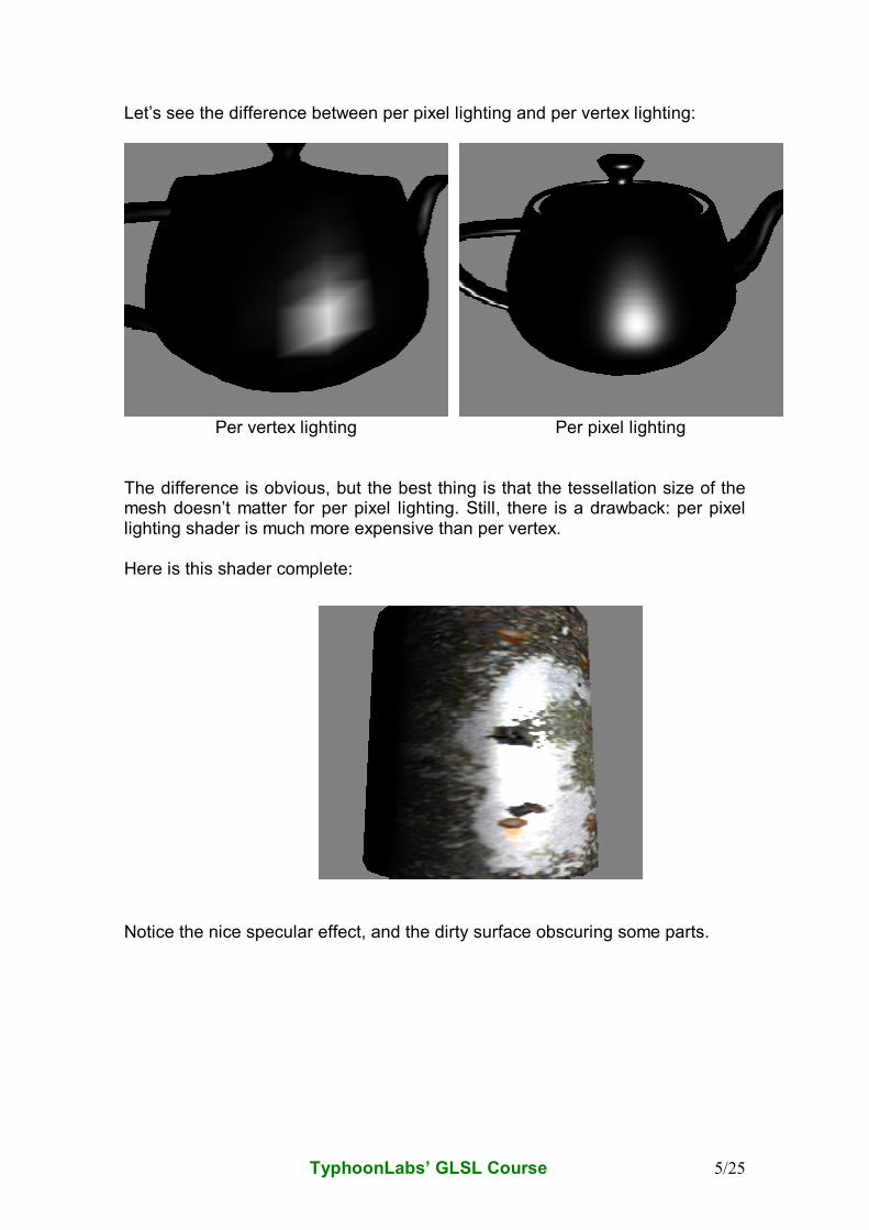
Let’s see the difference between per pixel lighting and per vertex lighting:
Per vertex lighting Per pixel lighting
The difference is obvious, but the best thing is that the tessellation size of the mesh doesn’t matter for per pixel lighting. Still, there is a drawback: per pixel lighting shader is much more expensive than per vertex. Here is this shader complete: Notice the nice specular effect, and the dirty surface obscuring some parts.
TyphoonLabs’ GLSL Course 6/25
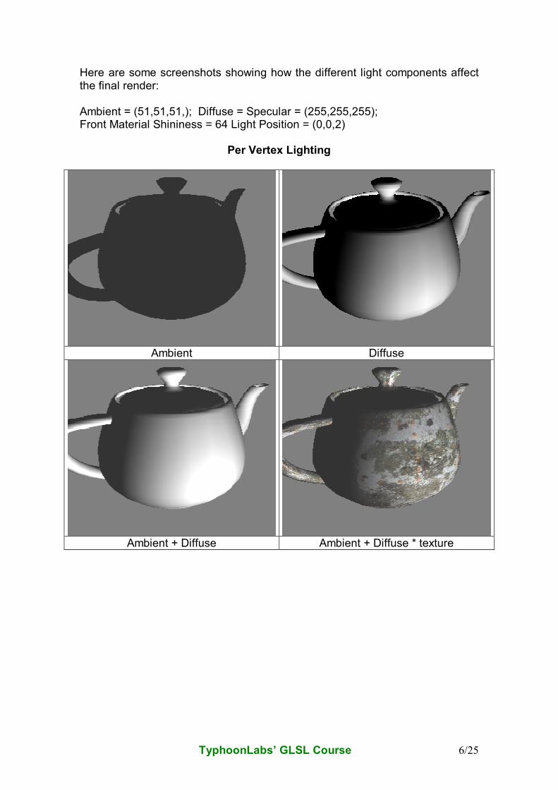
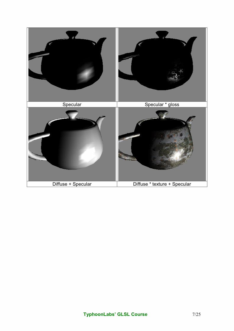
Here are some screenshots showing how the different light components affect the final render: Ambient = (51,51,51,); Diffuse = Specular = (255,255,255); Front Material Shininess = 64 Light Position = (0,0,2)
Per Vertex Lighting
Ambient Diffuse
Ambient + Diffuse Ambient + Diffuse * texture
TyphoonLabs’ GLSL Course 7/25
Specular Specular * gloss
Diffuse + Specular Diffuse * texture + Specular
TyphoonLabs’ GLSL Course 8/25
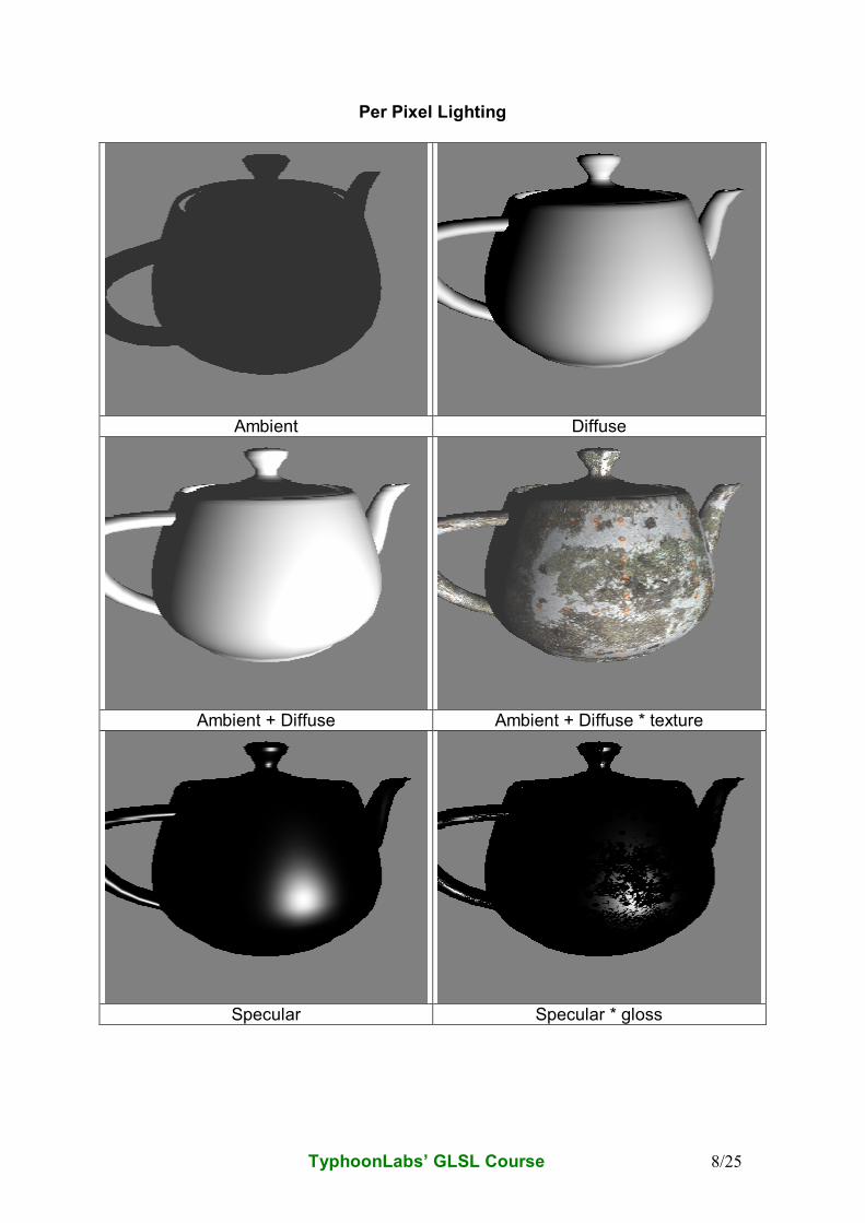
Per Pixel Lighting
Ambient Diffuse
Ambient + Diffuse Ambient + Diffuse * texture
Specular Specular * gloss
TyphoonLabs’ GLSL Course 9/25
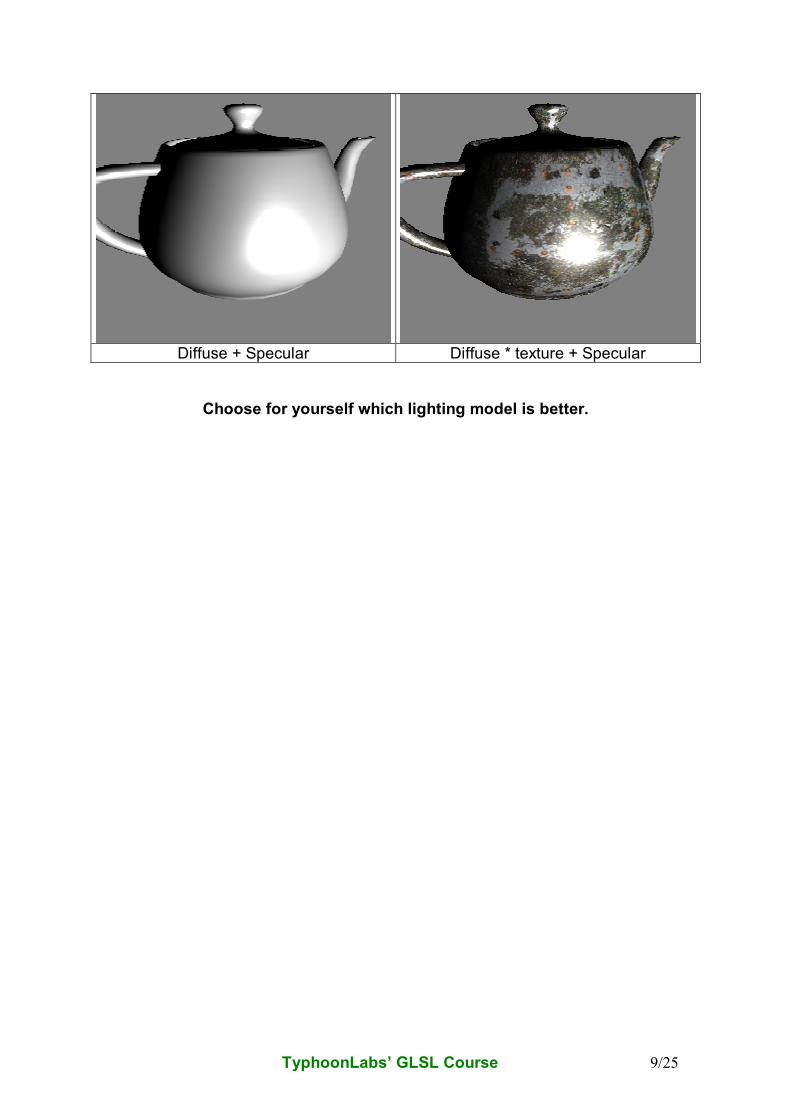
Diffuse + Specular Diffuse * texture + Specular
Choose for yourself which lighting model is better.
TyphoonLabs’ GLSL Course 10/25
Bump Mapping
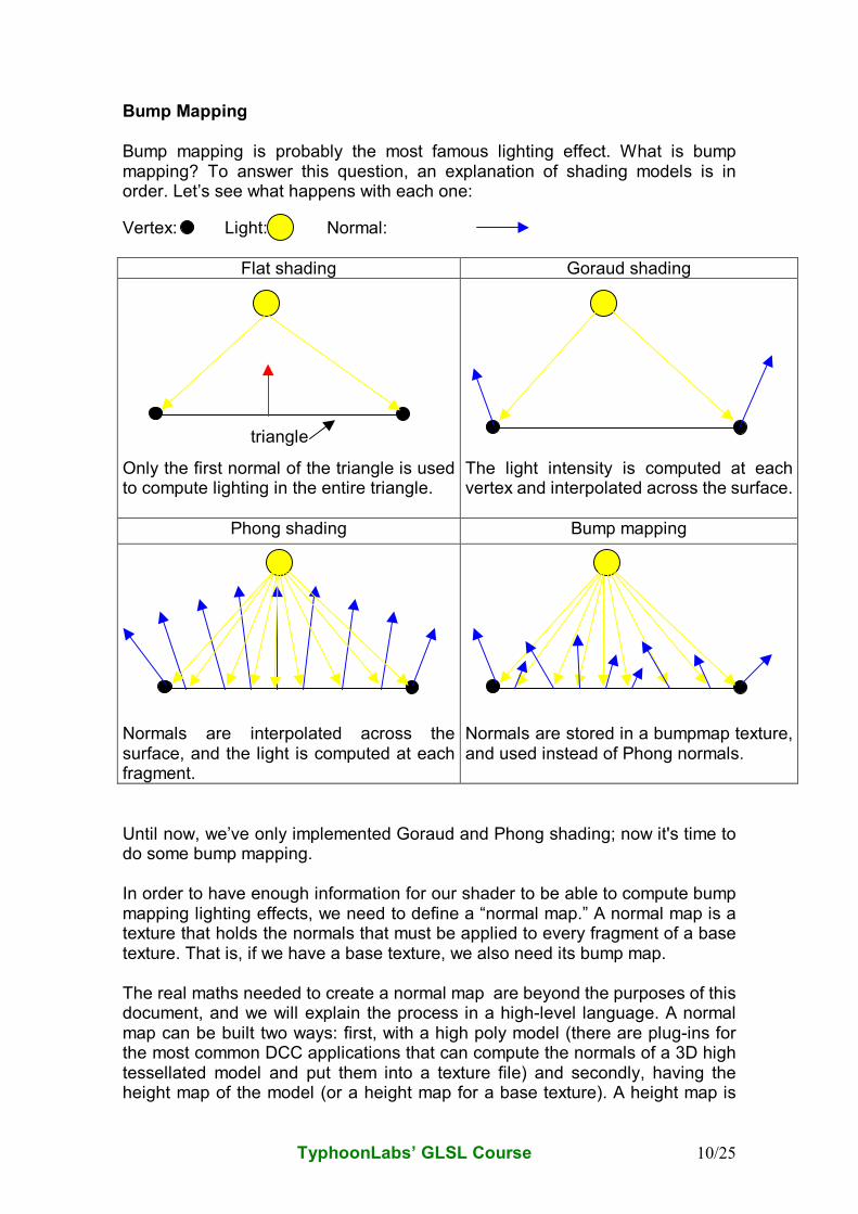
Bump mapping is probably the most famous lighting effect. What is bump mapping? To answer this question, an explanation of shading models is in order. Let’s see what happens with each one:
Vertex: Light: Normal:
Until now, we’ve only implemented Goraud and Phong shading; now it's time to do some bump mapping. In order to have enough information for our shader to be able to compute bump mapping lighting effects, we need to define a “normal map.” A normal map is a texture that holds the normals that must be applied to every fragment of a base texture. That is, if we have a base texture, we also need its bump map. The real maths needed to create a normal map are beyond the purposes of this document, and we will explain the process in a high-level language. A normal map can be built two ways: first, with a high poly model (there are plug-ins for the most common DCC applications that can compute the normals of a 3D high tessellated model and put them into a texture file) and secondly, having the height map of the model (or a height map for a base texture). A height map is
Flat shading Goraud shading
Only the first normal of the triangle is used to compute lighting in the entire triangle.
The light intensity is computed at each vertex and interpolated across the surface.
Phong shading Bump mapping
Normals are interpolated across the surface, and the light is computed at each fragment.
Normals are stored in a bumpmap texture, and used instead of Phong normals.
triangle
TyphoonLabs’ GLSL Course 11/25
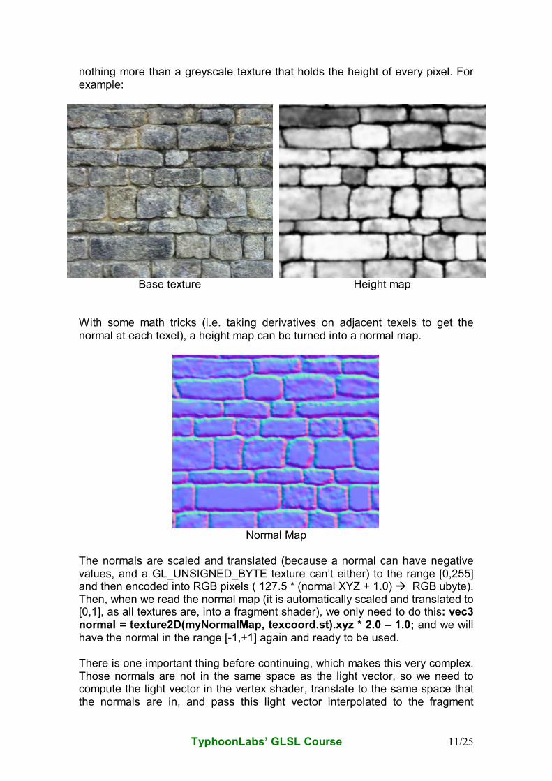
nothing more than a greyscale texture that holds the height of every pixel. For example:
Base texture Height map
With some math tricks (i.e. taking derivatives on adjacent texels to get the normal at each texel), a height map can be turned into a normal map.
Normal Map
The normals are scaled and translated (because a normal can have negative values, and a GL_UNSIGNED_BYTE texture can’t either) to the range [0,255] and then encoded into RGB pixels ( 127.5 * (normal XYZ + 1.0) � RGB ubyte). Then, when we read the normal map (it is automatically scaled and translated to [0,1], as all textures are, into a fragment shader), we only need to do this: vec3 normal = texture2D(myNormalMap, texcoord.st).xyz * 2.0 – 1.0; and we will have the normal in the range [-1,+1] again and ready to be used. There is one important thing before continuing, which makes this very complex. Those normals are not in the same space as the light vector, so we need to compute the light vector in the vertex shader, translate to the same space that the normals are in, and pass this light vector interpolated to the fragment
TyphoonLabs’ GLSL Course 12/25
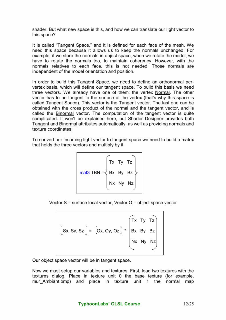
shader. But what new space is this, and how we can translate our light vector to this space? It is called “Tangent Space,” and it is defined for each face of the mesh. We need this space because it allows us to keep the normals unchanged. For example, if we store the normals in object space, when we rotate the model, we have to rotate the normals too, to maintain coherency. However, with the normals relatives to each face, this is not needed. Those normals are independent of the model orientation and position. In order to build this Tangent Space, we need to define an orthonormal per-vertex basis, which will define our tangent space. To build this basis we need three vectors. We already have one of them: the vertex Normal. The other vector has to be tangent to the surface at the vertex (that’s why this space is called Tangent Space). This vector is the Tangent vector. The last one can be obtained with the cross product of the normal and the tangent vector, and is called the Binormal vector. The computation of the tangent vector is quite complicated. It won't be explained here, but Shader Designer provides both Tangent and Binormal attributes automatically, as well as providing normals and texture coordinates. To convert our incoming light vector to tangent space we need to build a matrix that holds the three vectors and multiply by it.
Vector S = surface local vector, Vector O = object space vector Our object space vector will be in tangent space. Now we must setup our variables and textures. First, load two textures with the textures dialog. Place in texture unit 0 the base texture (for example, mur_Ambiant.bmp) and place in texture unit 1 the normal map
Tx Ty Tz mat3 TBN = Bx By Bz Nx Ny Nz
Tx Ty Tz Sx, Sy, Sz = Ox, Oy, Oz * Bx By Bz
Nx Ny Nz
TyphoonLabs’ GLSL Course 13/25
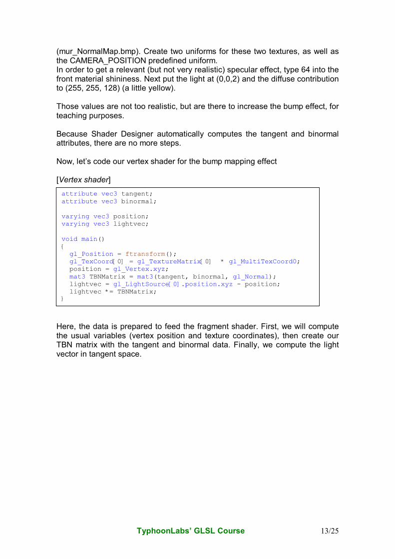
(mur_NormalMap.bmp). Create two uniforms for these two textures, as well as the CAMERA_POSITION predefined uniform. In order to get a relevant (but not very realistic) specular effect, type 64 into the front material shininess. Next put the light at (0,0,2) and the diffuse contribution to (255, 255, 128) (a little yellow). Those values are not too realistic, but are there to increase the bump effect, for teaching purposes. Because Shader Designer automatically computes the tangent and binormal attributes, there are no more steps. Now, let’s code our vertex shader for the bump mapping effect [Vertex shader] Here, the data is prepared to feed the fragment shader. First, we will compute the usual variables (vertex position and texture coordinates), then create our TBN matrix with the tangent and binormal data. Finally, we compute the light vector in tangent space.
attribute vec3 tangent; attribute vec3 binormal; varying vec3 position; varying vec3 lightvec; void main() { gl_Position = ftransform(); gl_TexCoord[0] = gl_TextureMatrix[0] * gl_MultiTexCoord0; position = gl_Vertex.xyz; mat3 TBNMatrix = mat3(tangent, binormal, gl_Normal); lightvec = gl_LightSource[0].position.xyz - position; lightvec *= TBNMatrix; }
TyphoonLabs’ GLSL Course 14/25
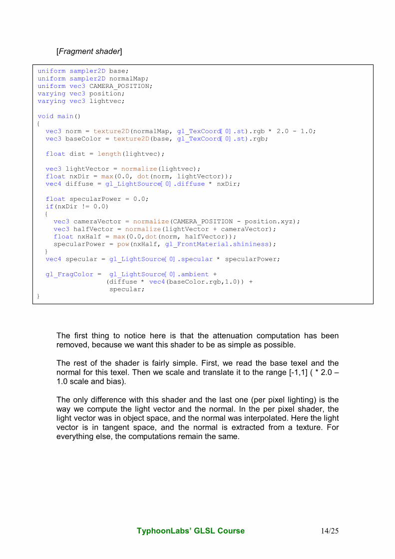
[Fragment shader] The first thing to notice here is that the attenuation computation has been removed, because we want this shader to be as simple as possible. The rest of the shader is fairly simple. First, we read the base texel and the normal for this texel. Then we scale and translate it to the range [-1,1] ( * 2.0 –1.0 scale and bias). The only difference with this shader and the last one (per pixel lighting) is the way we compute the light vector and the normal. In the per pixel shader, the light vector was in object space, and the normal was interpolated. Here the light vector is in tangent space, and the normal is extracted from a texture. For everything else, the computations remain the same.
uniform sampler2D base; uniform sampler2D normalMap; uniform vec3 CAMERA_POSITION; varying vec3 position; varying vec3 lightvec; void main() { vec3 norm = texture2D(normalMap, gl_TexCoord[0].st).rgb * 2.0 - 1.0; vec3 baseColor = texture2D(base, gl_TexCoord[0].st).rgb; float dist = length(lightvec); vec3 lightVector = normalize(lightvec); float nxDir = max(0.0, dot(norm, lightVector)); vec4 diffuse = gl_LightSource[0].diffuse * nxDir; float specularPower = 0.0; if(nxDir != 0.0) { vec3 cameraVector = normalize(CAMERA_POSITION - position.xyz); vec3 halfVector = normalize(lightVector + cameraVector); float nxHalf = max(0.0,dot(norm, halfVector)); specularPower = pow(nxHalf, gl_FrontMaterial.shininess); } vec4 specular = gl_LightSource[0].specular * specularPower; gl_FragColor = gl_LightSource[0].ambient + (diffuse * vec4(baseColor.rgb,1.0)) + specular; }
TyphoonLabs’ GLSL Course 15/25
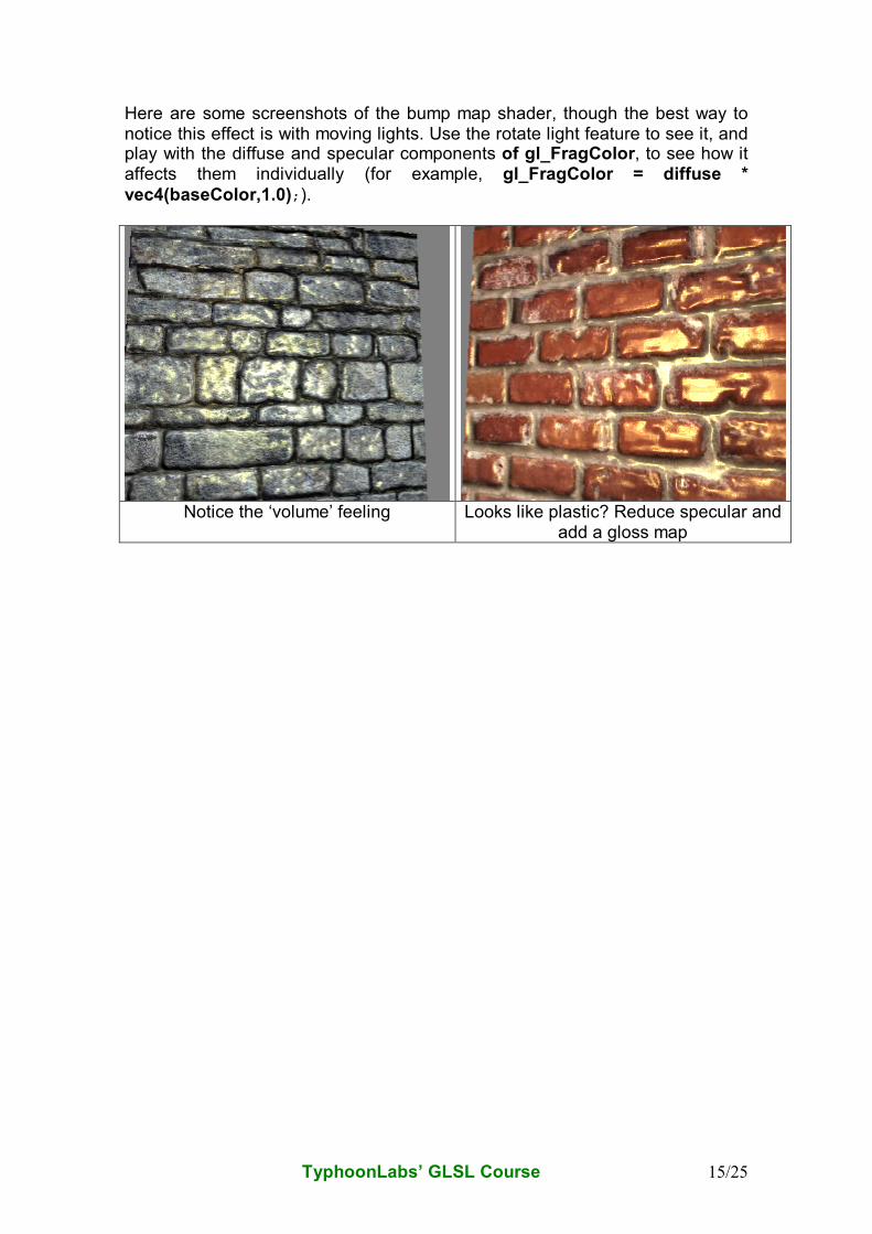
Here are some screenshots of the bump map shader, though the best way to notice this effect is with moving lights. Use the rotate light feature to see it, and play with the diffuse and specular components of gl_FragColor, to see how it affects them individually (for example, gl_FragColor = diffuse *
vec4(baseColor,1.0);).
Notice the ‘volume’ feeling Looks like plastic? Reduce specular and
add a gloss map
TyphoonLabs’ GLSL Course 16/25
Simple Parallax Mapping shader
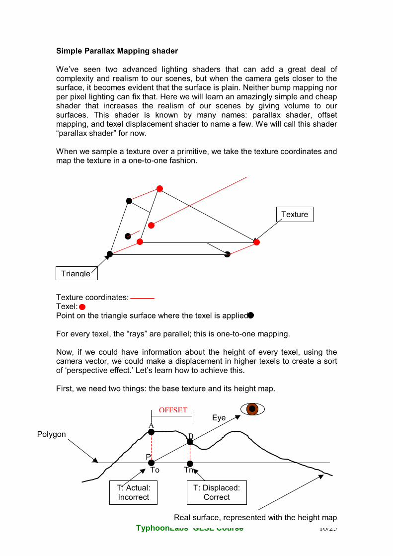
We’ve seen two advanced lighting shaders that can add a great deal of complexity and realism to our scenes, but when the camera gets closer to the surface, it becomes evident that the surface is plain. Neither bump mapping nor per pixel lighting can fix that. Here we will learn an amazingly simple and cheap shader that increases the realism of our scenes by giving volume to our surfaces. This shader is known by many names: parallax shader, offset mapping, and texel displacement shader to name a few. We will call this shader “parallax shader” for now. When we sample a texture over a primitive, we take the texture coordinates and map the texture in a one-to-one fashion. Texture coordinates: Texel: Point on the triangle surface where the texel is applied: For every texel, the “rays” are parallel; this is one-to-one mapping. Now, if we could have information about the height of every texel, using the camera vector, we could make a displacement in higher texels to create a sort of ‘perspective effect.’ Let’s learn how to achieve this. First, we need two things: the base texture and its height map.
Triangle
Texture
OFFSET
Polygon
Real surface, represented with the height map
T: Actual:
Incorrect
Eye
T: Displaced:
Correct
A
B
P
To Tn
TyphoonLabs’ GLSL Course 17/25
To achieve the desired effect we have to sample texel B, not texel A, so let’s see how to compute this offset in a cheap way. To compute a texture coordinate offset at a point P, the eye vector must first be normalized to produce a normalized eye vector V. The height h at the original texture coordinate To is read from the height map. The height is then scaled by a scale factor s and biased by a bias b in order to map the height from the range {0.0, 1.0} to a range that better represents the physical properties of the surface being simulated. The new scaled and biased height hsb is given by hsb = h · s + b.
An offset is then computed by tracing a vector parallel to the polygon from the point on the surface directly above P to the eye vector. This new vector is the offset and can be added to To to produce the new texture coordinate Tn.
Tn = To + ( hsb · V{x, y} )
The new texture coordinate is used to index a regular texture map and any other maps applied to the surface. This could seem too complex, but if you think about it carefully, you will see that it is actually fairly simple. Final considerations:
• The computations in the fragment shader must be in tangent space (the eye vector has to be in the same space as the height).
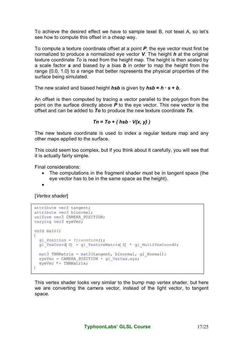
• [Vertex shader]
This vertex shader looks very similar to the bump map vertex shader, but here we are converting the camera vector, instead of the light vector, to tangent space.
attribute vec3 tangent; attribute vec3 binormal; uniform vec3 CAMERA_POSITION; varying vec3 eyeVec; void main() { gl_Position = ftransform(); gl_TexCoord[0] = gl_TextureMatrix[0] * gl_MultiTexCoord0; mat3 TBNMatrix = mat3(tangent, binormal, gl_Normal); eyeVec = CAMERA_POSITION - gl_Vertex.xyz; eyeVec *= TBNMatrix; }
TyphoonLabs’ GLSL Course 18/25
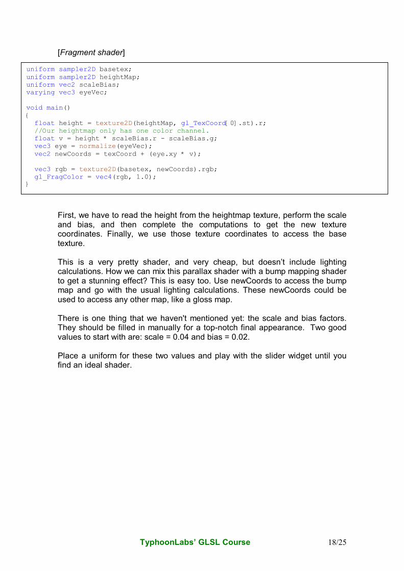
[Fragment shader]
First, we have to read the height from the heightmap texture, perform the scale and bias, and then complete the computations to get the new texture coordinates. Finally, we use those texture coordinates to access the base texture. This is a very pretty shader, and very cheap, but doesn’t include lighting calculations. How we can mix this parallax shader with a bump mapping shader to get a stunning effect? This is easy too. Use newCoords to access the bump map and go with the usual lighting calculations. These newCoords could be used to access any other map, like a gloss map. There is one thing that we haven't mentioned yet: the scale and bias factors. They should be filled in manually for a top-notch final appearance. Two good values to start with are: scale = 0.04 and bias = 0.02. Place a uniform for these two values and play with the slider widget until you find an ideal shader.
uniform sampler2D basetex; uniform sampler2D heightMap; uniform vec2 scaleBias; varying vec3 eyeVec; void main() { float height = texture2D(heightMap, gl_TexCoord[0].st).r; //Our heightmap only has one color channel. float v = height * scaleBias.r - scaleBias.g; vec3 eye = normalize(eyeVec); vec2 newCoords = texCoord + (eye.xy * v); vec3 rgb = texture2D(basetex, newCoords).rgb; gl_FragColor = vec4(rgb, 1.0); }
TyphoonLabs’ GLSL Course 19/25
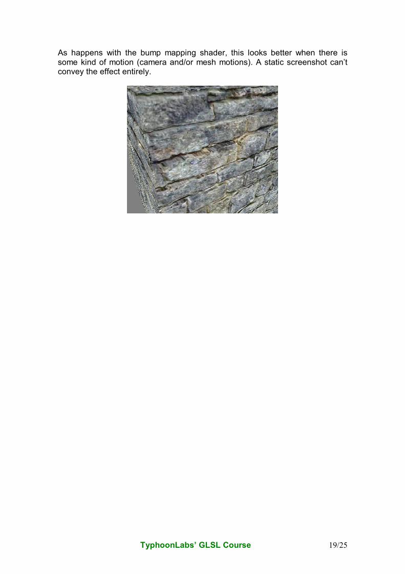
As happens with the bump mapping shader, this looks better when there is some kind of motion (camera and/or mesh motions). A static screenshot can’t convey the effect entirely.
TyphoonLabs’ GLSL Course 20/25
Mandelbrot Fractal Shader (Flow Control) Until now, we haven’t used many of the most important tools in every language: flow control and loops. To illustrate these tools we will write a shader that draws the fractal Mandelbrot set. The Mandelbrot set is defined as a recursive function based on imaginary numbers. We will use the plane ST (the one defined by the texture coordinates) to represent those imaginary numbers. The function itself is:
• Z0 = 0 + 0i;
• Zn+1= Z2n + C
One point is defined to be in the Mandelbrot set if its |Z| >= 2.0 (to avoid the square root, we will use this expression: |Z| *|Z| >= 4.0). If at any moment during the iterations, the |Z| *|Z| is greater than or equal to 4.0, we will end the loop and this point will be written with a linear interpolation (a gradient) of two colors (uniform variables) based on the number of iterations. If we reach the limit of the iterations (another uniform value), then this point may be outside the Mandelbrot set, and will be drawn with a black color. [Vertex shader] We’ve chosen the texture coordinates to parametrize our surface. By default, the texture coordinates are in the range [0,1], so we are going to remap this space to [-2.5,+2.5] .
varying vec3 position; void main() { position = vec3(gl_MultiTexCoord0 - 0.5) * 5.0; gl_Position = ftransform(); }
TyphoonLabs’ GLSL Course 21/25
[Fragment shader] Uniform variables table: Uniform name Initial value Slider min value Slider max value
maxIterations 50 1 128
center 0,0 -2.5 +2.5
outerColor1 (1,0,0) Color widget Color widget
outerColor2 (0,1,0) Color widget Color widget
zoom 1 1 Choose one
The only point that must be mentioned here is the center and zoom uniforms. These calculations are done to move the shader playing with the sliders. They are simply other scale and bias factors.
varying vec3 position; uniform int maxIterations; uniform vec2 center; uniform vec3 outerColor1; uniform vec3 outerColor2; uniform float zoom; void main() { float real = position.x * (1.0/zoom) + center.x; float imag = position.y * (1.0/zoom) + center.y; float cReal = real; float cImag = imag; float r2 = 0.0; int iter; for (iter = 0; iter < maxIterations && r2 < 4.0; ++iter) { float tempreal = real; real = (tempreal * tempreal) - (imag * imag) + cReal; imag = 2.0 * tempreal * imag + cImag; } // Base the color on the number of iterations. vec3 color; if (r2 < 4.0) color = vec3(0.0); else color = mix(outerColor1, outerColor2, fract(float(iter)*0.05)); gl_FragColor = vec4 (clamp(color, 0.0, 1.0), 1.0); }
TyphoonLabs’ GLSL Course 22/25
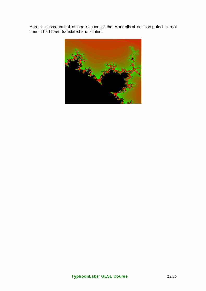
Here is a screenshot of one section of the Mandelbrot set computed in real time. It had been translated and scaled.
TyphoonLabs’ GLSL Course 23/25
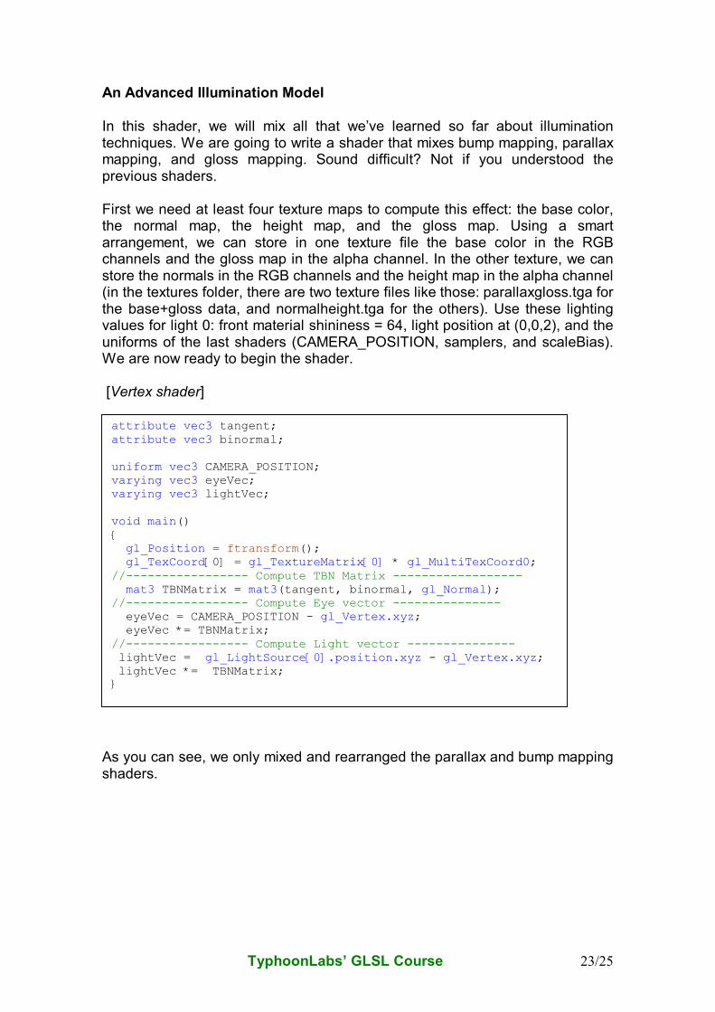
An Advanced Illumination Model In this shader, we will mix all that we’ve learned so far about illumination techniques. We are going to write a shader that mixes bump mapping, parallax mapping, and gloss mapping. Sound difficult? Not if you understood the previous shaders. First we need at least four texture maps to compute this effect: the base color, the normal map, the height map, and the gloss map. Using a smart arrangement, we can store in one texture file the base color in the RGB channels and the gloss map in the alpha channel. In the other texture, we can store the normals in the RGB channels and the height map in the alpha channel (in the textures folder, there are two texture files like those: parallaxgloss.tga for the base+gloss data, and normalheight.tga for the others). Use these lighting values for light 0: front material shininess = 64, light position at (0,0,2), and the uniforms of the last shaders (CAMERA_POSITION, samplers, and scaleBias). We are now ready to begin the shader. [Vertex shader]
As you can see, we only mixed and rearranged the parallax and bump mapping shaders.
attribute vec3 tangent; attribute vec3 binormal; uniform vec3 CAMERA_POSITION; varying vec3 eyeVec; varying vec3 lightVec; void main() { gl_Position = ftransform(); gl_TexCoord[0] = gl_TextureMatrix[0] * gl_MultiTexCoord0; //----------------- Compute TBN Matrix ------------------ mat3 TBNMatrix = mat3(tangent, binormal, gl_Normal); //----------------- Compute Eye vector --------------- eyeVec = CAMERA_POSITION - gl_Vertex.xyz; eyeVec *= TBNMatrix; //----------------- Compute Light vector --------------- lightVec = gl_LightSource[0].position.xyz - gl_Vertex.xyz; lightVec *= TBNMatrix; }
TyphoonLabs’ GLSL Course 24/25
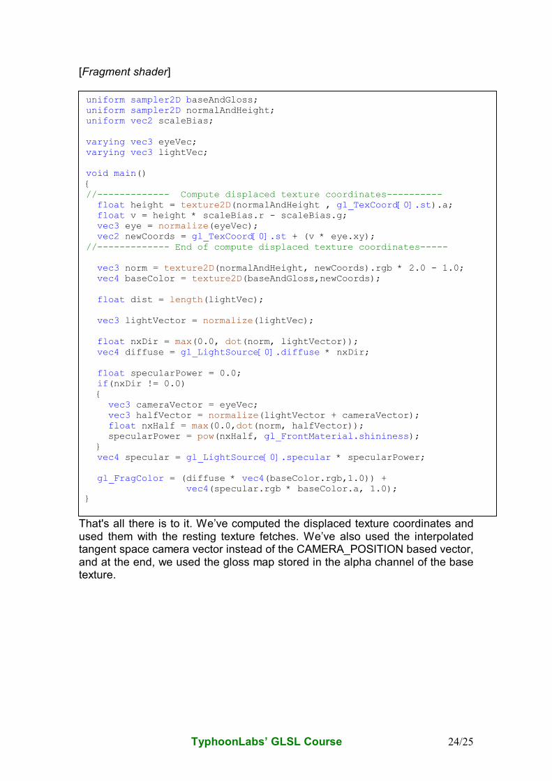
[Fragment shader]
That's all there is to it. We’ve computed the displaced texture coordinates and used them with the resting texture fetches. We’ve also used the interpolated tangent space camera vector instead of the CAMERA_POSITION based vector, and at the end, we used the gloss map stored in the alpha channel of the base texture.
uniform sampler2D baseAndGloss; uniform sampler2D normalAndHeight; uniform vec2 scaleBias; varying vec3 eyeVec; varying vec3 lightVec; void main() { //------------- Compute displaced texture coordinates---------- float height = texture2D(normalAndHeight , gl_TexCoord[0].st).a; float v = height * scaleBias.r - scaleBias.g; vec3 eye = normalize(eyeVec); vec2 newCoords = gl_TexCoord[0].st + (v * eye.xy); //------------- End of compute displaced texture coordinates----- vec3 norm = texture2D(normalAndHeight, newCoords).rgb * 2.0 - 1.0; vec4 baseColor = texture2D(baseAndGloss,newCoords); float dist = length(lightVec); vec3 lightVector = normalize(lightVec); float nxDir = max(0.0, dot(norm, lightVector)); vec4 diffuse = gl_LightSource[0].diffuse * nxDir; float specularPower = 0.0; if(nxDir != 0.0) { vec3 cameraVector = eyeVec; vec3 halfVector = normalize(lightVector + cameraVector); float nxHalf = max(0.0,dot(norm, halfVector)); specularPower = pow(nxHalf, gl_FrontMaterial.shininess); } vec4 specular = gl_LightSource[0].specular * specularPower; gl_FragColor = (diffuse * vec4(baseColor.rgb,1.0)) + vec4(specular.rgb * baseColor.a, 1.0); }
TyphoonLabs’ GLSL Course 25/25
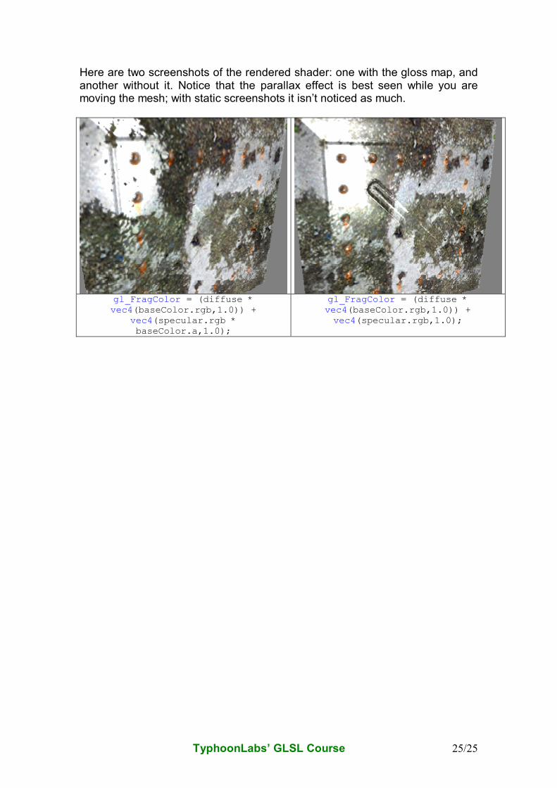
Here are two screenshots of the rendered shader: one with the gloss map, and another without it. Notice that the parallax effect is best seen while you are moving the mesh; with static screenshots it isn’t noticed as much.
gl_FragColor = (diffuse * vec4(baseColor.rgb,1.0)) +
vec4(specular.rgb * baseColor.a,1.0);
gl_FragColor = (diffuse * vec4(baseColor.rgb,1.0)) + vec4(specular.rgb,1.0);