Embed Size (px)
Citation preview

OpenGL R© ESVersion 3.0.5 (November 3, 2016)
Editors: Jon Leech, Benj Lipchak
Copyright c© 2006-2016 The Khronos Group Inc. All Rights Reserved.
This specification is protected by copyright laws and contains material proprietaryto the Khronos Group, Inc. It or any components may not be reproduced, repub-lished, distributed, transmitted, displayed, broadcast or otherwise exploited in anymanner without the express prior written permission of Khronos Group. You mayuse this specification for implementing the functionality therein, without altering orremoving any trademark, copyright or other notice from the specification, but thereceipt or possession of this specification does not convey any rights to reproduce,disclose, or distribute its contents, or to manufacture, use, or sell anything that itmay describe, in whole or in part.
Khronos Group grants express permission to any current Promoter, Contributoror Adopter member of Khronos to copy and redistribute UNMODIFIED versionsof this specification in any fashion, provided that NO CHARGE is made for thespecification and the latest available update of the specification for any versionof the API is used whenever possible. Such distributed specification may be re-formatted AS LONG AS the contents of the specification are not changed in anyway. The specification may be incorporated into a product that is sold as long assuch product includes significant independent work developed by the seller. A linkto the current version of this specification on the Khronos Group web-site shouldbe included whenever possible with specification distributions.
Khronos Group makes no, and expressly disclaims any, representations or war-ranties, express or implied, regarding this specification, including, without limita-tion, any implied warranties of merchantability or fitness for a particular purposeor non-infringement of any intellectual property. Khronos Group makes no, andexpressly disclaims any, warranties, express or implied, regarding the correctness,accuracy, completeness, timeliness, and reliability of the specification. Under nocircumstances will the Khronos Group, or any of its Promoters, Contributors orMembers or their respective partners, officers, directors, employees, agents or rep-resentatives be liable for any damages, whether direct, indirect, special or conse-quential damages for lost revenues, lost profits, or otherwise, arising from or inconnection with these materials.
Khronos is a trademark of The Khronos Group Inc. OpenGL is a registered trade-mark, and OpenGL ES is a trademark, of Silicon Graphics International.
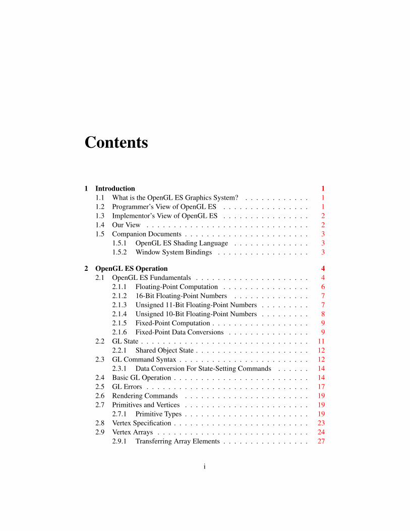
Contents
1 Introduction 11.1 What is the OpenGL ES Graphics System? . . . . . . . . . . . . 11.2 Programmer’s View of OpenGL ES . . . . . . . . . . . . . . . . 11.3 Implementor’s View of OpenGL ES . . . . . . . . . . . . . . . . 21.4 Our View . . . . . . . . . . . . . . . . . . . . . . . . . . . . . . 21.5 Companion Documents . . . . . . . . . . . . . . . . . . . . . . . 3
1.5.1 OpenGL ES Shading Language . . . . . . . . . . . . . . 31.5.2 Window System Bindings . . . . . . . . . . . . . . . . . 3
2 OpenGL ES Operation 42.1 OpenGL ES Fundamentals . . . . . . . . . . . . . . . . . . . . . 4
2.1.1 Floating-Point Computation . . . . . . . . . . . . . . . . 62.1.2 16-Bit Floating-Point Numbers . . . . . . . . . . . . . . 72.1.3 Unsigned 11-Bit Floating-Point Numbers . . . . . . . . . 72.1.4 Unsigned 10-Bit Floating-Point Numbers . . . . . . . . . 82.1.5 Fixed-Point Computation . . . . . . . . . . . . . . . . . . 92.1.6 Fixed-Point Data Conversions . . . . . . . . . . . . . . . 9
2.2 GL State . . . . . . . . . . . . . . . . . . . . . . . . . . . . . . . 112.2.1 Shared Object State . . . . . . . . . . . . . . . . . . . . . 12
2.3 GL Command Syntax . . . . . . . . . . . . . . . . . . . . . . . . 122.3.1 Data Conversion For State-Setting Commands . . . . . . 14
2.4 Basic GL Operation . . . . . . . . . . . . . . . . . . . . . . . . . 142.5 GL Errors . . . . . . . . . . . . . . . . . . . . . . . . . . . . . . 172.6 Rendering Commands . . . . . . . . . . . . . . . . . . . . . . . 192.7 Primitives and Vertices . . . . . . . . . . . . . . . . . . . . . . . 19
2.7.1 Primitive Types . . . . . . . . . . . . . . . . . . . . . . . 192.8 Vertex Specification . . . . . . . . . . . . . . . . . . . . . . . . . 232.9 Vertex Arrays . . . . . . . . . . . . . . . . . . . . . . . . . . . . 24
2.9.1 Transferring Array Elements . . . . . . . . . . . . . . . . 27
i
CONTENTS ii
2.9.2 Packed Vertex Data Formats . . . . . . . . . . . . . . . . 272.9.3 Drawing Commands . . . . . . . . . . . . . . . . . . . . 28
2.10 Buffer Objects . . . . . . . . . . . . . . . . . . . . . . . . . . . . 322.10.1 Creating and Binding Buffer Objects . . . . . . . . . . . 322.10.2 Creating Buffer Object Data Stores . . . . . . . . . . . . 352.10.3 Mapping and Unmapping Buffer Data . . . . . . . . . . . 372.10.4 Effects of Accessing Outside Buffer Bounds . . . . . . . 412.10.5 Copying Between Buffers . . . . . . . . . . . . . . . . . 412.10.6 Vertex Arrays in Buffer Objects . . . . . . . . . . . . . . 422.10.7 Array Indices in Buffer Objects . . . . . . . . . . . . . . 422.10.8 Buffer Object State . . . . . . . . . . . . . . . . . . . . . 43
2.11 Vertex Array Objects . . . . . . . . . . . . . . . . . . . . . . . . 432.12 Vertex Shaders . . . . . . . . . . . . . . . . . . . . . . . . . . . 44
2.12.1 Shader Objects . . . . . . . . . . . . . . . . . . . . . . . 452.12.2 Loading Shader Binaries . . . . . . . . . . . . . . . . . . 472.12.3 Program Objects . . . . . . . . . . . . . . . . . . . . . . 482.12.4 Program Binaries . . . . . . . . . . . . . . . . . . . . . . 532.12.5 Vertex Attributes . . . . . . . . . . . . . . . . . . . . . . 552.12.6 Uniform Variables . . . . . . . . . . . . . . . . . . . . . 582.12.7 Samplers . . . . . . . . . . . . . . . . . . . . . . . . . . 722.12.8 Output Variables . . . . . . . . . . . . . . . . . . . . . . 722.12.9 Shader Execution . . . . . . . . . . . . . . . . . . . . . . 752.12.10 Required State . . . . . . . . . . . . . . . . . . . . . . . 80
2.13 Coordinate Transformations . . . . . . . . . . . . . . . . . . . . 822.13.1 Controlling the Viewport . . . . . . . . . . . . . . . . . . 82
2.14 Asynchronous Queries . . . . . . . . . . . . . . . . . . . . . . . 832.15 Transform Feedback . . . . . . . . . . . . . . . . . . . . . . . . 85
2.15.1 Transform Feedback Objects . . . . . . . . . . . . . . . . 862.15.2 Transform Feedback Primitive Capture . . . . . . . . . . 87
2.16 Primitive Queries . . . . . . . . . . . . . . . . . . . . . . . . . . 912.17 Flatshading . . . . . . . . . . . . . . . . . . . . . . . . . . . . . 922.18 Primitive Clipping . . . . . . . . . . . . . . . . . . . . . . . . . . 92
2.18.1 Clipping Shader Outputs . . . . . . . . . . . . . . . . . . 93
3 Rasterization 953.1 Discarding Primitives Before Rasterization . . . . . . . . . . . . 963.2 Invariance . . . . . . . . . . . . . . . . . . . . . . . . . . . . . . 963.3 Multisampling . . . . . . . . . . . . . . . . . . . . . . . . . . . . 973.4 Points . . . . . . . . . . . . . . . . . . . . . . . . . . . . . . . . 98
3.4.1 Basic Point Rasterization . . . . . . . . . . . . . . . . . . 98
OpenGL ES 3.0.5 (November 3, 2016)
CONTENTS iii
3.4.2 Point Multisample Rasterization . . . . . . . . . . . . . . 993.5 Line Segments . . . . . . . . . . . . . . . . . . . . . . . . . . . 99
3.5.1 Basic Line Segment Rasterization . . . . . . . . . . . . . 993.5.2 Other Line Segment Features . . . . . . . . . . . . . . . . 1023.5.3 Line Rasterization State . . . . . . . . . . . . . . . . . . 1033.5.4 Line Multisample Rasterization . . . . . . . . . . . . . . 103
3.6 Polygons . . . . . . . . . . . . . . . . . . . . . . . . . . . . . . 1043.6.1 Basic Polygon Rasterization . . . . . . . . . . . . . . . . 1043.6.2 Depth Offset . . . . . . . . . . . . . . . . . . . . . . . . 1073.6.3 Polygon Multisample Rasterization . . . . . . . . . . . . 1083.6.4 Polygon Rasterization State . . . . . . . . . . . . . . . . 108
3.7 Pixel Rectangles . . . . . . . . . . . . . . . . . . . . . . . . . . . 1083.7.1 Pixel Storage Modes and Pixel Buffer Objects . . . . . . . 1093.7.2 Transfer of Pixel Rectangles . . . . . . . . . . . . . . . . 110
3.8 Texturing . . . . . . . . . . . . . . . . . . . . . . . . . . . . . . 1213.8.1 Texture Objects . . . . . . . . . . . . . . . . . . . . . . . 1223.8.2 Sampler Objects . . . . . . . . . . . . . . . . . . . . . . 1243.8.3 Texture Image Specification . . . . . . . . . . . . . . . . 1263.8.4 Immutable-Format Texture Images . . . . . . . . . . . . . 1363.8.5 Alternate Texture Image Specification Commands . . . . 1393.8.6 Compressed Texture Images . . . . . . . . . . . . . . . . 1453.8.7 Texture Parameters . . . . . . . . . . . . . . . . . . . . . 1493.8.8 Depth Component Textures . . . . . . . . . . . . . . . . 1513.8.9 Cube Map Texture Selection . . . . . . . . . . . . . . . . 1513.8.10 Texture Minification . . . . . . . . . . . . . . . . . . . . 1523.8.11 Texture Magnification . . . . . . . . . . . . . . . . . . . 1603.8.12 Combined Depth/Stencil Textures . . . . . . . . . . . . . 1603.8.13 Texture Completeness . . . . . . . . . . . . . . . . . . . 1603.8.14 Texture State . . . . . . . . . . . . . . . . . . . . . . . . 1623.8.15 Texture Comparison Modes . . . . . . . . . . . . . . . . 1633.8.16 sRGB Texture Color Conversion . . . . . . . . . . . . . . 1643.8.17 Shared Exponent Texture Color Conversion . . . . . . . . 165
3.9 Fragment Shaders . . . . . . . . . . . . . . . . . . . . . . . . . . 1653.9.1 Shader Variables . . . . . . . . . . . . . . . . . . . . . . 1653.9.2 Shader Execution . . . . . . . . . . . . . . . . . . . . . . 166
4 Per-Fragment Operations and the Framebuffer 1714.1 Per-Fragment Operations . . . . . . . . . . . . . . . . . . . . . . 172
4.1.1 Pixel Ownership Test . . . . . . . . . . . . . . . . . . . . 1734.1.2 Scissor Test . . . . . . . . . . . . . . . . . . . . . . . . . 173
OpenGL ES 3.0.5 (November 3, 2016)
CONTENTS iv
4.1.3 Multisample Fragment Operations . . . . . . . . . . . . . 1744.1.4 Stencil Test . . . . . . . . . . . . . . . . . . . . . . . . . 1754.1.5 Depth Buffer Test . . . . . . . . . . . . . . . . . . . . . . 1774.1.6 Occlusion Queries . . . . . . . . . . . . . . . . . . . . . 1774.1.7 Blending . . . . . . . . . . . . . . . . . . . . . . . . . . 1784.1.8 sRGB Conversion . . . . . . . . . . . . . . . . . . . . . 1824.1.9 Dithering . . . . . . . . . . . . . . . . . . . . . . . . . . 1834.1.10 Additional Multisample Fragment Operations . . . . . . . 183
4.2 Whole Framebuffer Operations . . . . . . . . . . . . . . . . . . . 1844.2.1 Selecting Buffers for Writing . . . . . . . . . . . . . . . . 1844.2.2 Fine Control of Buffer Updates . . . . . . . . . . . . . . 1864.2.3 Clearing the Buffers . . . . . . . . . . . . . . . . . . . . 187
4.3 Reading and Copying Pixels . . . . . . . . . . . . . . . . . . . . 1904.3.1 Selecting Buffers for Reading . . . . . . . . . . . . . . . 1904.3.2 Reading Pixels . . . . . . . . . . . . . . . . . . . . . . . 1914.3.3 Copying Pixels . . . . . . . . . . . . . . . . . . . . . . . 1964.3.4 Pixel Draw/Read State . . . . . . . . . . . . . . . . . . . 198
4.4 Framebuffer Objects . . . . . . . . . . . . . . . . . . . . . . . . 1994.4.1 Binding and Managing Framebuffer Objects . . . . . . . . 1994.4.2 Attaching Images to Framebuffer Objects . . . . . . . . . 2024.4.3 Feedback Loops Between Textures and the Framebuffer . 2104.4.4 Framebuffer Completeness . . . . . . . . . . . . . . . . . 2124.4.5 Effects of Framebuffer State on Framebuffer Dependent
Values . . . . . . . . . . . . . . . . . . . . . . . . . . . . 2174.4.6 Mapping between Pixel and Element in Attached Image . 218
4.5 Invalidating Framebuffer Contents . . . . . . . . . . . . . . . . . 219
5 Special Functions 2215.1 Flush and Finish . . . . . . . . . . . . . . . . . . . . . . . . . . . 2215.2 Sync Objects and Fences . . . . . . . . . . . . . . . . . . . . . . 221
5.2.1 Waiting for Sync Objects . . . . . . . . . . . . . . . . . . 2235.2.2 Signalling . . . . . . . . . . . . . . . . . . . . . . . . . . 225
5.3 Hints . . . . . . . . . . . . . . . . . . . . . . . . . . . . . . . . . 226
6 State and State Requests 2276.1 Querying GL State . . . . . . . . . . . . . . . . . . . . . . . . . 227
6.1.1 Simple Queries . . . . . . . . . . . . . . . . . . . . . . . 2276.1.2 Data Conversions . . . . . . . . . . . . . . . . . . . . . . 2286.1.3 Enumerated Queries . . . . . . . . . . . . . . . . . . . . 2286.1.4 Texture Queries . . . . . . . . . . . . . . . . . . . . . . . 229
OpenGL ES 3.0.5 (November 3, 2016)
CONTENTS v
6.1.5 Sampler Queries . . . . . . . . . . . . . . . . . . . . . . 2296.1.6 String Queries . . . . . . . . . . . . . . . . . . . . . . . 2306.1.7 Asynchronous Queries . . . . . . . . . . . . . . . . . . . 2316.1.8 Sync Object Queries . . . . . . . . . . . . . . . . . . . . 2326.1.9 Buffer Object Queries . . . . . . . . . . . . . . . . . . . 2336.1.10 Vertex Array Object Queries . . . . . . . . . . . . . . . . 2346.1.11 Transform Feedback Queries . . . . . . . . . . . . . . . . 2356.1.12 Shader and Program Queries . . . . . . . . . . . . . . . . 2356.1.13 Framebuffer Object Queries . . . . . . . . . . . . . . . . 2406.1.14 Renderbuffer Object Queries . . . . . . . . . . . . . . . . 2436.1.15 Internal Format Queries . . . . . . . . . . . . . . . . . . 244
6.2 State Tables . . . . . . . . . . . . . . . . . . . . . . . . . . . . . 245
A Invariance 282A.1 Repeatability . . . . . . . . . . . . . . . . . . . . . . . . . . . . 282A.2 Multi-pass Algorithms . . . . . . . . . . . . . . . . . . . . . . . 283A.3 Invariance Rules . . . . . . . . . . . . . . . . . . . . . . . . . . . 283A.4 What All This Means . . . . . . . . . . . . . . . . . . . . . . . . 284
B Corollaries 286
C Compressed Texture Image Formats 288C.1 ETC Compressed Texture Image Formats . . . . . . . . . . . . . 288
C.1.1 Format COMPRESSED_RGB8_ETC2 . . . . . . . . . . . . 291C.1.2 Format COMPRESSED_SRGB8_ETC2 . . . . . . . . . . . . 298C.1.3 Format COMPRESSED_RGBA8_ETC2_EAC . . . . . . . . . 298C.1.4 Format COMPRESSED_SRGB8_ALPHA8_ETC2_EAC . . . . 301C.1.5 Format COMPRESSED_R11_EAC . . . . . . . . . . . . . . 301C.1.6 Format COMPRESSED_RG11_EAC . . . . . . . . . . . . . 304C.1.7 Format COMPRESSED_SIGNED_R11_EAC . . . . . . . . . 305C.1.8 Format COMPRESSED_SIGNED_RG11_EAC . . . . . . . . 308C.1.9 Format
COMPRESSED_RGB8_PUNCHTHROUGH_ALPHA1_ETC2 . . 308C.1.10 Format
COMPRESSED_SRGB8_PUNCHTHROUGH_ALPHA1_ETC2 . 315
D Shared Objects and Multiple Contexts 316D.1 Object Deletion Behavior . . . . . . . . . . . . . . . . . . . . . . 316
D.1.1 Side Effects of Shared Context Destruction . . . . . . . . 316D.1.2 Automatic Unbinding of Deleted Objects . . . . . . . . . 317
OpenGL ES 3.0.5 (November 3, 2016)
CONTENTS vi
D.1.3 Deleted Object and Object Name Lifetimes . . . . . . . . 317D.2 Sync Objects and Multiple Contexts . . . . . . . . . . . . . . . . 318D.3 Propagating Changes to Objects . . . . . . . . . . . . . . . . . . 318
D.3.1 Determining Completion of Changes to an object . . . . . 319D.3.2 Definitions . . . . . . . . . . . . . . . . . . . . . . . . . 319D.3.3 Rules . . . . . . . . . . . . . . . . . . . . . . . . . . . . 319
E Version 3.0 and Before 321E.1 New Features . . . . . . . . . . . . . . . . . . . . . . . . . . . . 321E.2 Change Log for 3.0.5, November 3, 2016 . . . . . . . . . . . . . 323E.3 Change Log for 3.0.4 . . . . . . . . . . . . . . . . . . . . . . . . 324E.4 Change Log for 3.0.3 . . . . . . . . . . . . . . . . . . . . . . . . 324E.5 Change Log for 3.0.2 . . . . . . . . . . . . . . . . . . . . . . . . 326E.6 Change Log for 3.0.1 . . . . . . . . . . . . . . . . . . . . . . . . 327E.7 Credits and Acknowledgements . . . . . . . . . . . . . . . . . . 329
F OpenGL ES 2.0 Compatibility 332F.1 Legacy Features . . . . . . . . . . . . . . . . . . . . . . . . . . . 332F.2 Differences in Runtime Behavior . . . . . . . . . . . . . . . . . . 333
Index 334
OpenGL ES 3.0.5 (November 3, 2016)
List of Figures
2.1 Block diagram of the GL. . . . . . . . . . . . . . . . . . . . . . . 142.2 Vertex processing and primitive assembly. . . . . . . . . . . . . . 192.3 Triangle strips, fans, and independent triangles. . . . . . . . . . . 21
3.1 Rasterization. . . . . . . . . . . . . . . . . . . . . . . . . . . . . 953.2 Visualization of Bresenham’s algorithm. . . . . . . . . . . . . . . 1003.3 Rasterization of wide lines. . . . . . . . . . . . . . . . . . . . . . 1023.4 The region used in rasterizing a multisampled line segment. . . . . 1033.5 Transfer of pixel rectangles. . . . . . . . . . . . . . . . . . . . . 1103.6 Selecting a subimage from an image . . . . . . . . . . . . . . . . 1163.7 A texture image and the coordinates used to access it. . . . . . . . 135
4.1 Per-fragment operations. . . . . . . . . . . . . . . . . . . . . . . 1724.2 Operation of ReadPixels. . . . . . . . . . . . . . . . . . . . . . . 191
vii
List of Tables
2.1 GL command suffixes . . . . . . . . . . . . . . . . . . . . . . . . 132.2 GL data types . . . . . . . . . . . . . . . . . . . . . . . . . . . . 152.3 Summary of GL errors . . . . . . . . . . . . . . . . . . . . . . . 182.4 Vertex array sizes (values per vertex) and data types . . . . . . . . 252.5 Packed component layout. . . . . . . . . . . . . . . . . . . . . . 282.6 Buffer object binding targets. . . . . . . . . . . . . . . . . . . . . 332.7 Buffer object parameters and their values. . . . . . . . . . . . . . 342.8 Buffer object initial state. . . . . . . . . . . . . . . . . . . . . . . 362.9 Buffer object state set by MapBufferRange. . . . . . . . . . . . 392.10 OpenGL ES Shading Language type tokens . . . . . . . . . . . . 642.11 Output types for OpenGL ES Shading Language variables . . . . 902.12 Provoking vertex selection. . . . . . . . . . . . . . . . . . . . . . 92
3.1 PixelStorei parameters. . . . . . . . . . . . . . . . . . . . . . . . 1093.2 Valid combinations of format, type, and sized internalformat. . . . 1123.3 Valid combinations of format, type, and unsized internalformat. . 1133.4 Pixel data types. . . . . . . . . . . . . . . . . . . . . . . . . . . . 1143.5 Pixel data formats. . . . . . . . . . . . . . . . . . . . . . . . . . 1153.6 Packed pixel formats. . . . . . . . . . . . . . . . . . . . . . . . . 1173.7 UNSIGNED_SHORT formats . . . . . . . . . . . . . . . . . . . . . 1183.8 UNSIGNED_INT formats . . . . . . . . . . . . . . . . . . . . . . 1193.9 FLOAT_UNSIGNED_INT formats . . . . . . . . . . . . . . . . . . 1193.10 Packed pixel field assignments. . . . . . . . . . . . . . . . . . . . 1203.11 Conversion from RGBA, depth, and stencil pixel components to
internal texture components. . . . . . . . . . . . . . . . . . . . . 1273.12 Effective internal format corresponding to external format and type. 1283.13 Sized internal color formats. . . . . . . . . . . . . . . . . . . . . 1323.14 Sized internal depth and stencil formats. . . . . . . . . . . . . . . 1333.15 ReadPixels format and type used during CopyTex*. . . . . . . . 140
viii
LIST OF TABLES ix
3.16 Valid CopyTexImage source framebuffer/destination texture baseinternal format combinations. . . . . . . . . . . . . . . . . . . . . 140
3.17 Effective internal format corresponding to destination internalfor-mat and linear source buffer component sizes. . . . . . . . . . . . 142
3.18 Effective internal format corresponding to destination internalfor-mat and sRGB source buffer component sizes. . . . . . . . . . . . 142
3.19 Compressed internal formats. . . . . . . . . . . . . . . . . . . . . 1473.20 Texture parameters and their values. . . . . . . . . . . . . . . . . 1503.21 Selection of cube map images. . . . . . . . . . . . . . . . . . . . 1513.22 Texel location wrap mode application. . . . . . . . . . . . . . . . 1563.23 Depth texture comparison functions. . . . . . . . . . . . . . . . . 1643.24 Correspondence of filtered texture components to texture base
components. . . . . . . . . . . . . . . . . . . . . . . . . . . . . . 168
4.1 RGB and Alpha blend equations. . . . . . . . . . . . . . . . . . . 1804.2 Blending functions. . . . . . . . . . . . . . . . . . . . . . . . . . 1814.3 Buffer selection for a framebuffer object . . . . . . . . . . . . . . 1844.4 PixelStorei parameters. . . . . . . . . . . . . . . . . . . . . . . . 1924.5 ReadPixels GL data types and reversed component conversion for-
mulas. . . . . . . . . . . . . . . . . . . . . . . . . . . . . . . . . 1954.6 Framebuffer attachment points. . . . . . . . . . . . . . . . . . . . 206
5.1 Initial properties of a sync object created with FenceSync. . . . . 2235.2 Hint targets and descriptions . . . . . . . . . . . . . . . . . . . . 226
6.1 State Variable Types . . . . . . . . . . . . . . . . . . . . . . . . . 2466.2 Vertex Array Object State . . . . . . . . . . . . . . . . . . . . . . 2476.3 Vertex Array Data (not in vertex array objects) . . . . . . . . . . . 2486.4 Buffer Object State . . . . . . . . . . . . . . . . . . . . . . . . . 2496.5 Transformation State . . . . . . . . . . . . . . . . . . . . . . . . 2506.6 Rasterization . . . . . . . . . . . . . . . . . . . . . . . . . . . . 2516.7 Multisampling . . . . . . . . . . . . . . . . . . . . . . . . . . . . 2526.8 Textures (selector, state per texture unit) . . . . . . . . . . . . . . 2536.9 Textures (state per texture object) . . . . . . . . . . . . . . . . . . 2546.10 Textures (state per sampler object) . . . . . . . . . . . . . . . . . 2556.11 Pixel Operations . . . . . . . . . . . . . . . . . . . . . . . . . . . 2566.12 Framebuffer Control . . . . . . . . . . . . . . . . . . . . . . . . 2576.13 Framebuffer (state per framebuffer object) . . . . . . . . . . . . . 2586.14 Framebuffer (state per attachment point) . . . . . . . . . . . . . . 2596.15 Renderbuffer (state per renderbuffer object) . . . . . . . . . . . . 260
OpenGL ES 3.0.5 (November 3, 2016)
LIST OF TABLES x
6.16 Pixels . . . . . . . . . . . . . . . . . . . . . . . . . . . . . . . . 2616.17 Shader Object State . . . . . . . . . . . . . . . . . . . . . . . . . 2626.18 Program Object State . . . . . . . . . . . . . . . . . . . . . . . . 2636.19 Program Object State (cont.) . . . . . . . . . . . . . . . . . . . . 2646.20 Program Object State (cont.) . . . . . . . . . . . . . . . . . . . . 2656.21 Program Object State (cont.) . . . . . . . . . . . . . . . . . . . . 2666.22 Vertex Shader State (not part of program objects) . . . . . . . . . 2676.23 Query Object State . . . . . . . . . . . . . . . . . . . . . . . . . 2686.24 Transform Feedback State . . . . . . . . . . . . . . . . . . . . . 2696.25 Uniform Buffer Binding State . . . . . . . . . . . . . . . . . . . 2706.26 Sync (state per sync object) . . . . . . . . . . . . . . . . . . . . . 2716.27 Hints . . . . . . . . . . . . . . . . . . . . . . . . . . . . . . . . . 2726.28 Implementation Dependent Values . . . . . . . . . . . . . . . . . 2736.29 Implementation Dependent Values (cont.) . . . . . . . . . . . . . 2746.30 Implementation Dependent Version and Extension Support . . . . 2756.31 Implementation Dependent Vertex Shader Limits . . . . . . . . . 2766.32 Implementation Dependent Fragment Shader Limits . . . . . . . . 2776.33 Implementation Dependent Aggregate Shader Limits . . . . . . . 2786.34 Implementation Dependent Transform Feedback Limits . . . . . . 2796.35 Framebuffer Dependent Values . . . . . . . . . . . . . . . . . . . 2806.36 Miscellaneous . . . . . . . . . . . . . . . . . . . . . . . . . . . . 281
C.1 Pixel layout for a 8 × 8 texture using four COMPRESSED_RGB8_-ETC2 compressed blocks. . . . . . . . . . . . . . . . . . . . . . . 290
C.2 Pixel layout for an COMPRESSED_RGB8_ETC2 compressed block. 292C.3 Texel Data format for RGB8_ETC2 compressed textures formats . 293C.4 Two 2× 4-pixel subblocks side-by-side. . . . . . . . . . . . . . . 294C.5 Two 4× 2-pixel subblocks on top of each other. . . . . . . . . . . 294C.6 Intensity modifier sets for ‘individual’ and ‘differential’ modes: . . 295C.7 Mapping from pixel index values to modifier values for
COMPRESSED_RGB8_ETC2 compressed textures . . . . . . . . . . 295C.8 Distance table for ‘T’ and ‘H’ modes. . . . . . . . . . . . . . . . 296C.9 Texel Data format for alpha part of COMPRESSED_RGBA8_ETC2_-
EAC compressed textures. . . . . . . . . . . . . . . . . . . . . . . 299C.10 Intensity modifier sets for alpha component. . . . . . . . . . . . . 300C.11 Texel Data format for RGB8_PUNCHTHROUGH_ALPHA1_ETC2
compressed textures formats . . . . . . . . . . . . . . . . . . . . 309C.12 Intensity modifier sets if ‘opaque’ is set and if ‘opaque’ is unset. . 311
OpenGL ES 3.0.5 (November 3, 2016)

LIST OF TABLES xi
C.13 Mapping from pixel index values to modifier values forCOMPRESSED_RGB8_PUNCHTHROUGH_ALPHA1_ETC2 compressedtextures . . . . . . . . . . . . . . . . . . . . . . . . . . . . . . . 312
OpenGL ES 3.0.5 (November 3, 2016)
Chapter 1
Introduction
This document describes the OpenGL ES graphics system: what it is, how it acts,and what is required to implement it. We assume that the reader has at least arudimentary understanding of computer graphics. This means familiarity with theessentials of computer graphics algorithms as well as familiarity with basic graph-ics hardware and associated terms.
1.1 What is the OpenGL ES Graphics System?
OpenGL ES (“Open Graphics Library for Embedded Systems”) is a software in-terface to graphics hardware. The interface consists of a set of several hundredcommands that allow a programmer to specify the objects and operations involvedin producing high-quality graphical images, specifically color images of three-dimensional objects.
Most of OpenGL ES requires that the graphics hardware contain a framebuffer.Many OpenGL ES calls pertain to drawing objects such as points, lines, and poly-gons, but the way that some of this drawing occurs relies on the existence of aframebuffer. Further, some of OpenGL ES is specifically concerned with frame-buffer manipulation.
1.2 Programmer’s View of OpenGL ES
To the programmer, OpenGL ES is a set of commands that allow the specificationof geometric objects in two or three dimensions, together with commands thatcontrol how these objects are rendered into the framebuffer.
A typical program that uses OpenGL ES begins with calls to open a windowinto the framebuffer into which the program will draw. Then, calls are made to
1
1.3. IMPLEMENTOR’S VIEW OF OPENGL ES 2
allocate an OpenGL ES context and associate it with the window. Once an OpenGLES context is allocated, the programmer is free to issue OpenGL ES commands.Some calls are used to draw simple geometric objects (i.e. points, line segments,and polygons), while others affect the rendering of these primitives including howthey are lit or colored and how they are mapped from the user’s two- or three-dimensional model space to the two-dimensional screen. There are also calls toeffect direct control of the framebuffer, such as reading and writing pixels.
1.3 Implementor’s View of OpenGL ES
To the implementor, OpenGL ES is a set of commands that affect the operation ofgraphics hardware. If the hardware consists only of an addressable framebuffer,then OpenGL ES must be implemented almost entirely on the host CPU. Moretypically, the graphics hardware may comprise varying degrees of graphics accel-eration, from a raster subsystem capable of rendering two-dimensional lines andpolygons to sophisticated floating-point processors capable of transforming andcomputing on geometric data. The OpenGL ES implementor’s task is to providethe CPU software interface while dividing the work for each OpenGL ES com-mand between the CPU and the graphics hardware. This division must be tailoredto the available graphics hardware to obtain optimum performance in carrying outOpenGL ES calls.
OpenGL ES maintains a considerable amount of state information. This statecontrols how objects are drawn into the framebuffer. Some of this state is directlyavailable to the user: he or she can make calls to obtain its value. Some of it,however, is visible only by the effect it has on what is drawn. One of the maingoals of this specification is to make OpenGL ES state information explicit, toelucidate how it changes, and to indicate what its effects are.
1.4 Our View
We view OpenGL ES as a pipeline having some programmable stages and somestate-driven stages that control a set of specific drawing operations. This modelshould engender a specification that satisfies the needs of both programmers andimplementors. It does not, however, necessarily provide a model for implementa-tion. An implementation must produce results conforming to those produced bythe specified methods, but there may be ways to carry out a particular computationthat are more efficient than the one specified.
OpenGL ES 3.0.5 (November 3, 2016)
1.5. COMPANION DOCUMENTS 3
1.5 Companion Documents
1.5.1 OpenGL ES Shading Language
This specification should be read together with a companion document titled TheOpenGL ES Shading Language. The latter document (referred to as the OpenGLES Shading Language Specification hereafter) defines the syntax and semanticsof the programming language used to write vertex and fragment shaders (see sec-tions 2.12 and 3.9). These sections may include references to concepts and terms(such as shading language variable types) defined in the companion document.
OpenGL ES 3.0 implementations are guaranteed to support versions 3.00 and1.00 of the OpenGL ES Shading Language. All references to sections of that spec-ification refer to version 3.00. The latest supported version of the shading languagemay be queried as described in section 6.1.5.
1.5.2 Window System Bindings
OpenGL ES requires a companion API to create and manage graphics contexts,windows to render into, and other resources beyond the scope of this Specification.There are several such APIs supporting different operating and window systems.
The Khronos Native Platform Graphics Interface or “EGL Specification” de-scribes the EGL API for use of OpenGL ES on mobile and embedded devices.EGL implementations may be available supporting OpenGL as well. The EGLSpecification is available in the Khronos Extension Registry at URL
http://www.khronos.org/registry/egl
The EAGL API supports use of OpenGL ES with iOS. EAGL is documentedon Apple’s developer website.
OpenGL ES 3.0.5 (November 3, 2016)
Chapter 2
OpenGL ES Operation
2.1 OpenGL ES Fundamentals
OpenGL ES (henceforth, the “GL”) is concerned only with rendering into a frame-buffer (and reading values stored in that framebuffer). There is no support forother peripherals sometimes associated with graphics hardware, such as mice andkeyboards. Programmers must rely on other mechanisms to obtain user input.
The GL draws primitives subject to a number of selectable modes and shaderprograms. Each primitive is a point, line segment, or polygon. Each mode maybe changed independently; the setting of one does not affect the settings of oth-ers (although many modes may interact to determine what eventually ends up inthe framebuffer). Modes are set, primitives specified, and other GL operationsdescribed by sending commands in the form of function or procedure calls.
Primitives are defined by a group of one or more vertices. A vertex definesa point, an endpoint of an edge, or a corner of a polygon where two edges meet.Data such as positional coordinates, colors, normals, texture coordinates, etc. areassociated with a vertex and each vertex is processed independently, in order, andin the same way. The only exception to this rule is if the group of vertices mustbe clipped so that the indicated primitive fits within a specified region; in thiscase vertex data may be modified and new vertices created. The type of clippingdepends on which primitive the group of vertices represents.
Commands are always processed in the order in which they are received, al-though there may be an indeterminate delay before the effects of a command arerealized. This means, for example, that one primitive must be drawn completelybefore any subsequent one can affect the framebuffer. It also means that queriesand pixel read operations return state consistent with complete execution of allpreviously invoked GL commands, except where explicitly specified otherwise. In
4
2.1. OPENGL ES FUNDAMENTALS 5
general, the effects of a GL command on either GL modes or the framebuffer mustbe complete before any subsequent command can have any such effects.
In the GL, data binding occurs on call. This means that data passed to a com-mand are interpreted when that command is received. Even if the command re-quires a pointer to data, those data are interpreted when the call is made, and anysubsequent changes to the data have no effect on the GL (unless the same pointeris used in a subsequent command).
The GL provides direct control over the fundamental operations of 3D and 2Dgraphics. This includes specification of parameters of application-defined shaderprograms performing transformation, lighting, texturing, and shading operations,as well as built-in functionality such as texture filtering. It does not provide ameans for describing or modeling complex geometric objects. Another way todescribe this situation is to say that the GL provides mechanisms to describe howcomplex geometric objects are to be rendered rather than mechanisms to describethe complex objects themselves.
The model for interpretation of GL commands is client-server. That is, a pro-gram (the client) issues commands, and these commands are interpreted and pro-cessed by the GL (the server). The server may or may not operate on the samecomputer as the client. In this sense, the GL is network-transparent. A server maymaintain a number of GL contexts, each of which is an encapsulation of currentGL state. A client may choose to connect to any one of these contexts. IssuingGL commands when the program is not connected to a context results in undefinedbehavior.
The GL interacts with two classes of framebuffers: window system-providedand application-created. There is at most one window system-provided framebufferat any time, referred to as the default framebuffer. Application-created frame-buffers, referred to as framebuffer objects, may be created as desired. These twotypes of framebuffer are distinguished primarily by the interface for configuringand managing their state.
The effects of GL commands on the default framebuffer are ultimately con-trolled by the window system, which allocates framebuffer resources, determineswhich portions of the default framebuffer the GL may access at any given time, andcommunicates to the GL how those portions are structured. Therefore, there areno GL commands to initialize a GL context or configure the default framebuffer.Similarly, display of framebuffer contents on a physical display device (includingthe transformation of individual framebuffer values by such techniques as gammacorrection) is not addressed by the GL.
Allocation and configuration of the default framebuffer occurs outside of theGL in conjunction with the window system, using companion APIs described insection 1.5.2.
OpenGL ES 3.0.5 (November 3, 2016)
2.1. OPENGL ES FUNDAMENTALS 6
Allocation and initialization of GL contexts is also done using these companionAPIs. GL contexts can typically be associated with different default framebuffers,and some context state is determined at the time this association is performed.
It is possible to use a GL context without a default framebuffer, in which casea framebuffer object must be used to perform all rendering. This is useful forapplications needing to perform offscreen rendering.
The GL is designed to be run on a range of graphics platforms with varyinggraphics capabilities and performance. To accommodate this variety, we specifyideal behavior instead of actual behavior for certain GL operations. In cases wheredeviation from the ideal is allowed, we also specify the rules that an implemen-tation must obey if it is to approximate the ideal behavior usefully. This allowedvariation in GL behavior implies that two distinct GL implementations may notagree pixel for pixel when presented with the same input even when run on identi-cal framebuffer configurations.
Finally, command names, constants, and types are prefixed in the GL (by gl,GL_, and GL, respectively in C) to reduce name clashes with other packages. Theprefixes are omitted in this document for clarity.
2.1.1 Floating-Point Computation
The GL must perform a number of floating-point operations during the course ofits operation. In some cases, the representation and/or precision of such operationsis defined or limited; by the OpenGL ES Shading Language Specification for op-erations in shaders, and in some cases implicitly limited by the specified formatof vertex, texture, or renderbuffer data consumed by the GL. Otherwise, the rep-resentation of such floating-point numbers, and the details of how operations onthem are performed, is not specified. We require simply that numbers’ floating-point parts contain enough bits and that their exponent fields are large enough sothat individual results of floating-point operations are accurate to about 1 part in105. The maximum representable magnitude for all floating-point values must beat least 232. x ·0 = 0 ·x = 0 for any non-infinite and non-NaN x. 1 ·x = x ·1 = x.x+ 0 = 0 + x = x. 00 = 1. (Occasionally further requirements will be specified.)Most single-precision floating-point formats meet these requirements.
The special values Inf and −Inf encode values with magnitudes too large tobe represented; the special value NaN encodes “Not A Number” values resultingfrom undefined arithmetic operations such as 0
0 . Implementations are permitted,but not required, to support Inf s and NaN s in their floating-point computations.
Any representable floating-point value is legal as input to a GL command thatrequires floating-point data. The result of providing a value that is not a floating-point number to such a command is unspecified, but must not lead to GL interrup-
OpenGL ES 3.0.5 (November 3, 2016)
2.1. OPENGL ES FUNDAMENTALS 7
tion or termination. In IEEE arithmetic, for example, providing a negative zero or adenormalized number to a GL command yields predictable results, while providinga NaN or an infinity yields unspecified results.
Some calculations require division. In such cases (including implied divisionsrequired by vector normalizations), a division by zero produces an unspecified re-sult but must not lead to GL interruption or termination.
2.1.2 16-Bit Floating-Point Numbers
A 16-bit floating-point number has a 1-bit sign (S), a 5-bit exponent (E), and a10-bit mantissa (M ). The value V of a 16-bit floating-point number is determinedby the following:
V =
(−1)S × 0.0, E = 0,M = 0
(−1)S × 2−14 × M210, E = 0,M 6= 0
(−1)S × 2E−15 ×(1 + M
210
), 0 < E < 31
(−1)S × Inf , E = 31,M = 0
NaN , E = 31,M 6= 0
If the floating-point number is interpreted as an unsigned 16-bit integerN , then
S =
⌊N mod 65536
32768
⌋E =
⌊N mod 32768
1024
⌋M = N mod 1024.
Any representable 16-bit floating-point value is legal as input to a GL commandthat accepts 16-bit floating-point data. The result of providing a value that is not afloating-point number (such as Inf or NaN ) to such a command is unspecified, butmust not lead to GL interruption or termination. Providing a denormalized numberor negative zero to GL must yield predictable results, whereby the value is eitherpreserved or forced to positive or negative zero.
2.1.3 Unsigned 11-Bit Floating-Point Numbers
An unsigned 11-bit floating-point number has no sign bit, a 5-bit exponent (E), anda 6-bit mantissa (M ). The value V of an unsigned 11-bit floating-point number isdetermined by the following:
OpenGL ES 3.0.5 (November 3, 2016)
2.1. OPENGL ES FUNDAMENTALS 8
V =
0.0, E = 0,M = 0
2−14 × M64 , E = 0,M 6= 0
2E−15 ×(1 + M
64
), 0 < E < 31
Inf , E = 31,M = 0
NaN , E = 31,M 6= 0
If the floating-point number is interpreted as an unsigned 11-bit integerN , then
E =
⌊N
64
⌋M = N mod 64.
When a floating-point value is converted to an unsigned 11-bit floating-pointrepresentation, finite values are rounded to the closest representable finite value.While less accurate, implementations are allowed to always round in the directionof zero. This means negative values are converted to zero. Likewise, finite posi-tive values greater than 65024 (the maximum finite representable unsigned 11-bitfloating-point value) are converted to 65024. Additionally: negative infinity is con-verted to zero; positive infinity is converted to positive infinity; and both positiveand negative NaN are converted to positive NaN .
Any representable unsigned 11-bit floating-point value is legal as input to aGL command that accepts 11-bit floating-point data. The result of providing avalue that is not a floating-point number (such as Inf or NaN ) to such a commandis unspecified, but must not lead to GL interruption or termination. Providing adenormalized number to GL must yield predictable results, whereby the value iseither preserved or forced to zero.
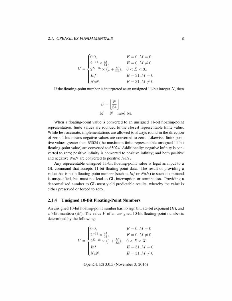
2.1.4 Unsigned 10-Bit Floating-Point Numbers
An unsigned 10-bit floating-point number has no sign bit, a 5-bit exponent (E), anda 5-bit mantissa (M ). The value V of an unsigned 10-bit floating-point number isdetermined by the following:
V =
0.0, E = 0,M = 0
2−14 × M32 , E = 0,M 6= 0
2E−15 ×(1 + M
32
), 0 < E < 31
Inf , E = 31,M = 0
NaN , E = 31,M 6= 0
OpenGL ES 3.0.5 (November 3, 2016)
2.1. OPENGL ES FUNDAMENTALS 9
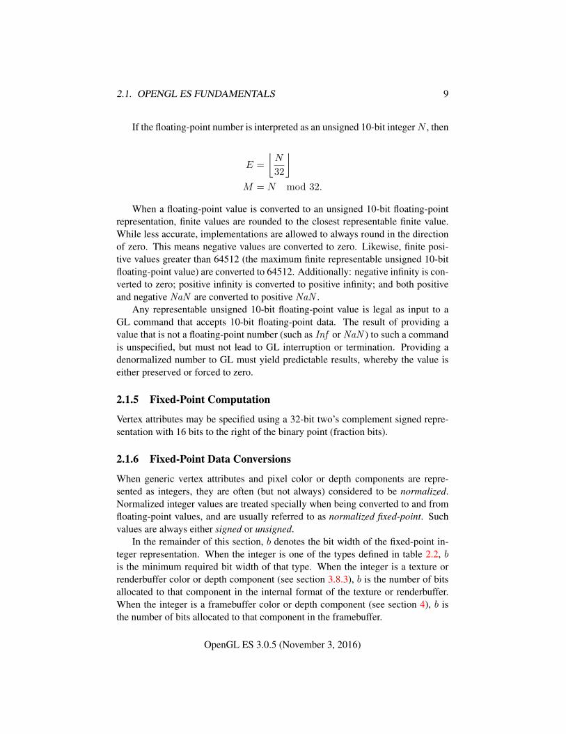
If the floating-point number is interpreted as an unsigned 10-bit integerN , then
E =
⌊N
32
⌋M = N mod 32.
When a floating-point value is converted to an unsigned 10-bit floating-pointrepresentation, finite values are rounded to the closest representable finite value.While less accurate, implementations are allowed to always round in the directionof zero. This means negative values are converted to zero. Likewise, finite posi-tive values greater than 64512 (the maximum finite representable unsigned 10-bitfloating-point value) are converted to 64512. Additionally: negative infinity is con-verted to zero; positive infinity is converted to positive infinity; and both positiveand negative NaN are converted to positive NaN .
Any representable unsigned 10-bit floating-point value is legal as input to aGL command that accepts 10-bit floating-point data. The result of providing avalue that is not a floating-point number (such as Inf or NaN ) to such a commandis unspecified, but must not lead to GL interruption or termination. Providing adenormalized number to GL must yield predictable results, whereby the value iseither preserved or forced to zero.
2.1.5 Fixed-Point Computation
Vertex attributes may be specified using a 32-bit two’s complement signed repre-sentation with 16 bits to the right of the binary point (fraction bits).
2.1.6 Fixed-Point Data Conversions
When generic vertex attributes and pixel color or depth components are repre-sented as integers, they are often (but not always) considered to be normalized.Normalized integer values are treated specially when being converted to and fromfloating-point values, and are usually referred to as normalized fixed-point. Suchvalues are always either signed or unsigned.
In the remainder of this section, b denotes the bit width of the fixed-point in-teger representation. When the integer is one of the types defined in table 2.2, bis the minimum required bit width of that type. When the integer is a texture orrenderbuffer color or depth component (see section 3.8.3), b is the number of bitsallocated to that component in the internal format of the texture or renderbuffer.When the integer is a framebuffer color or depth component (see section 4), b isthe number of bits allocated to that component in the framebuffer.
OpenGL ES 3.0.5 (November 3, 2016)
2.1. OPENGL ES FUNDAMENTALS 10
The signed and unsigned fixed-point representations are assumed to be b-bitbinary two’s-complement integers and binary unsigned integers, respectively.
All the conversions described below are performed as defined, even if the im-plemented range of an integer data type is greater than the minimum required range.
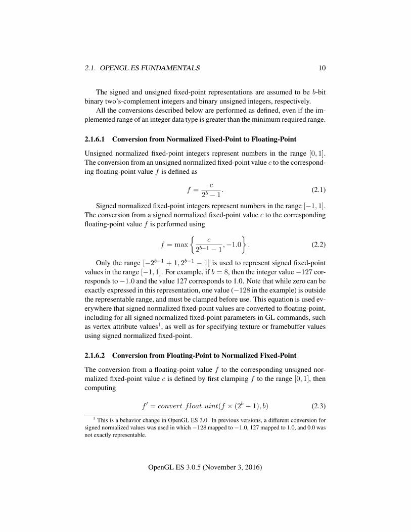
2.1.6.1 Conversion from Normalized Fixed-Point to Floating-Point
Unsigned normalized fixed-point integers represent numbers in the range [0, 1].The conversion from an unsigned normalized fixed-point value c to the correspond-ing floating-point value f is defined as
f =c
2b − 1. (2.1)
Signed normalized fixed-point integers represent numbers in the range [−1, 1].The conversion from a signed normalized fixed-point value c to the correspondingfloating-point value f is performed using
f = max
{c
2b−1 − 1,−1.0
}. (2.2)
Only the range [−2b−1 + 1, 2b−1 − 1] is used to represent signed fixed-pointvalues in the range [−1, 1]. For example, if b = 8, then the integer value−127 cor-responds to−1.0 and the value 127 corresponds to 1.0. Note that while zero can beexactly expressed in this representation, one value (−128 in the example) is outsidethe representable range, and must be clamped before use. This equation is used ev-erywhere that signed normalized fixed-point values are converted to floating-point,including for all signed normalized fixed-point parameters in GL commands, suchas vertex attribute values1, as well as for specifying texture or framebuffer valuesusing signed normalized fixed-point.
2.1.6.2 Conversion from Floating-Point to Normalized Fixed-Point
The conversion from a floating-point value f to the corresponding unsigned nor-malized fixed-point value c is defined by first clamping f to the range [0, 1], thencomputing
f ′ = convert float uint(f × (2b − 1), b) (2.3)
1 This is a behavior change in OpenGL ES 3.0. In previous versions, a different conversion forsigned normalized values was used in which−128 mapped to−1.0, 127 mapped to 1.0, and 0.0 wasnot exactly representable.
OpenGL ES 3.0.5 (November 3, 2016)
2.2. GL STATE 11
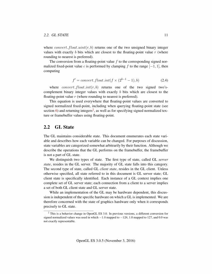
where convert float uint(r, b) returns one of the two unsigned binary integervalues with exactly b bits which are closest to the floating-point value r (whererounding to nearest is preferred).
The conversion from a floating-point value f to the corresponding signed nor-malized fixed-point value c is performed by clamping f to the range [−1, 1], thencomputing
f ′ = convert float int(f × (2b−1 − 1), b) (2.4)
where convert float int(r, b) returns one of the two signed two’s-complement binary integer values with exactly b bits which are closest to thefloating-point value r (where rounding to nearest is preferred).
This equation is used everywhere that floating-point values are converted tosigned normalized fixed-point, including when querying floating-point state (seesection 6) and returning integers2, as well as for specifying signed normalized tex-ture or framebuffer values using floating-point.
2.2 GL State
The GL maintains considerable state. This document enumerates each state vari-able and describes how each variable can be changed. For purposes of discussion,state variables are categorized somewhat arbitrarily by their function. Although wedescribe the operations that the GL performs on the framebuffer, the framebufferis not a part of GL state.
We distinguish two types of state. The first type of state, called GL serverstate, resides in the GL server. The majority of GL state falls into this category.The second type of state, called GL client state, resides in the GL client. Unlessotherwise specified, all state referred to in this document is GL server state; GLclient state is specifically identified. Each instance of a GL context implies onecomplete set of GL server state; each connection from a client to a server impliesa set of both GL client state and GL server state.
While an implementation of the GL may be hardware dependent, this discus-sion is independent of the specific hardware on which a GL is implemented. We aretherefore concerned with the state of graphics hardware only when it correspondsprecisely to GL state.
2 This is a behavior change in OpenGL ES 3.0. In previous versions, a different conversion forsigned normalized values was used in which−1.0 mapped to−128, 1.0 mapped to 127, and 0.0 wasnot exactly representable.
OpenGL ES 3.0.5 (November 3, 2016)
2.3. GL COMMAND SYNTAX 12
2.2.1 Shared Object State
It is possible for groups of contexts to share certain state. Enabling such sharingbetween contexts is done through window system binding APIs such as those de-scribed in section 1.5.2. These APIs are responsible for creation and managementof contexts and are not discussed further here. More detailed discussion of thebehavior of shared objects is included in appendix D. Except as defined in thisappendix, all state in a context is specific to that context only.
2.3 GL Command Syntax
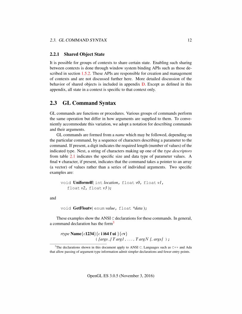
GL commands are functions or procedures. Various groups of commands performthe same operation but differ in how arguments are supplied to them. To conve-niently accommodate this variation, we adopt a notation for describing commandsand their arguments.
GL commands are formed from a name which may be followed, depending onthe particular command, by a sequence of characters describing a parameter to thecommand. If present, a digit indicates the required length (number of values) of theindicated type. Next, a string of characters making up one of the type descriptorsfrom table 2.1 indicates the specific size and data type of parameter values. Afinal v character, if present, indicates that the command takes a pointer to an array(a vector) of values rather than a series of individual arguments. Two specificexamples are:
void Uniform4f( int location, float v0, float v1,float v2, float v3 );
and
void GetFloatv( enum value, float *data );
These examples show the ANSI C declarations for these commands. In general,a command declaration has the form3
rtype Name{ε1234}{ε i i64 f ui }{εv}( [args ,] T arg1 , . . . , T argN [, args] );
3The declarations shown in this document apply to ANSI C. Languages such as C++ and Adathat allow passing of argument type information admit simpler declarations and fewer entry points.
OpenGL ES 3.0.5 (November 3, 2016)

2.3. GL COMMAND SYNTAX 13
Type Descriptor Corresponding GL Typei int
i64 int64f float
ui uint
Table 2.1: Correspondence of command suffix type descriptors to GL argumenttypes. Refer to table 2.2 for definitions of the GL types.
rtype is the return type of the function. The braces ({}) enclose a series of typedescriptors (see table 2.1), of which one is selected. ε indicates no type descriptor.The arguments enclosed in brackets ([args ,] and [, args]) may or may not bepresent. The N arguments arg1 through argN have type T, which corresponds toone of the type descriptors indicated in table 2.1 (if there are no letters, then thearguments’ type is given explicitly). If the final character is not v, then N is givenby the digit 1, 2, 3, or 4 (if there is no digit, then the number of arguments is fixed).If the final character is v, then only arg1 is present and it is an array of N values ofthe indicated type.
For example,
void Uniform{1234}{if}( int location, T value );
indicates the eight declarations
void Uniform1i( int location, int value );void Uniform1f( int location, float value );void Uniform2i( int location, int v0, int v1 );void Uniform2f( int location, float v0, float v1 );void Uniform3i( int location, int v0, int v1, int v2 );void Uniform3f( int location, float v0, float v1,
float v2 );void Uniform4i( int location, int v0, int v1, int v2,
int v3 );void Uniform4f( int location, float v0, float v1,
float v2, float v3 );
Arguments whose type is fixed (i.e. not indicated by a suffix on the command)are of one of the GL data types summarized in table 2.2, or pointers to one of these
OpenGL ES 3.0.5 (November 3, 2016)
2.4. BASIC GL OPERATION 14
types.4
2.3.1 Data Conversion For State-Setting Commands
Many GL commands specify a value or values to which GL state of a specific type(boolean, enum, integer, or floating-point) is to be set. When multiple versions ofsuch a command exist, using the type descriptor syntax described above, any suchversion may be used to set the state value. When state values are specified usinga different parameter type than the actual type of that state, data conversions areperformed as follows:
• When the type of internal state is boolean, zero integer or floating-point val-ues are converted to FALSE and non-zero values are converted to TRUE.
• When the type of internal state is integer or enum, boolean values of FALSEand TRUE are converted to 0 and 1, respectively. Floating-point values arerounded to the nearest integer. If the resulting value is so large in magnitudethat it cannot be represented by the internal state variable, the internal statevalue is undefined.
• When the type of internal state is floating-point, boolean values of FALSEand TRUE are converted to 0.0 and 1.0, respectively. Integer values are con-verted to floating-point.
For commands taking arrays of the specified type, these conversions are per-formed for each element of the passed array.
Each command following these conversion rules refers back to this section.Some commands have additional conversion rules specific to certain state valuesand data types, which are described following the reference.
Validation of values performed by state-setting commands is performed afterconversion, unless specified otherwise for a specific command.
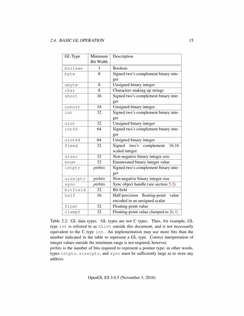
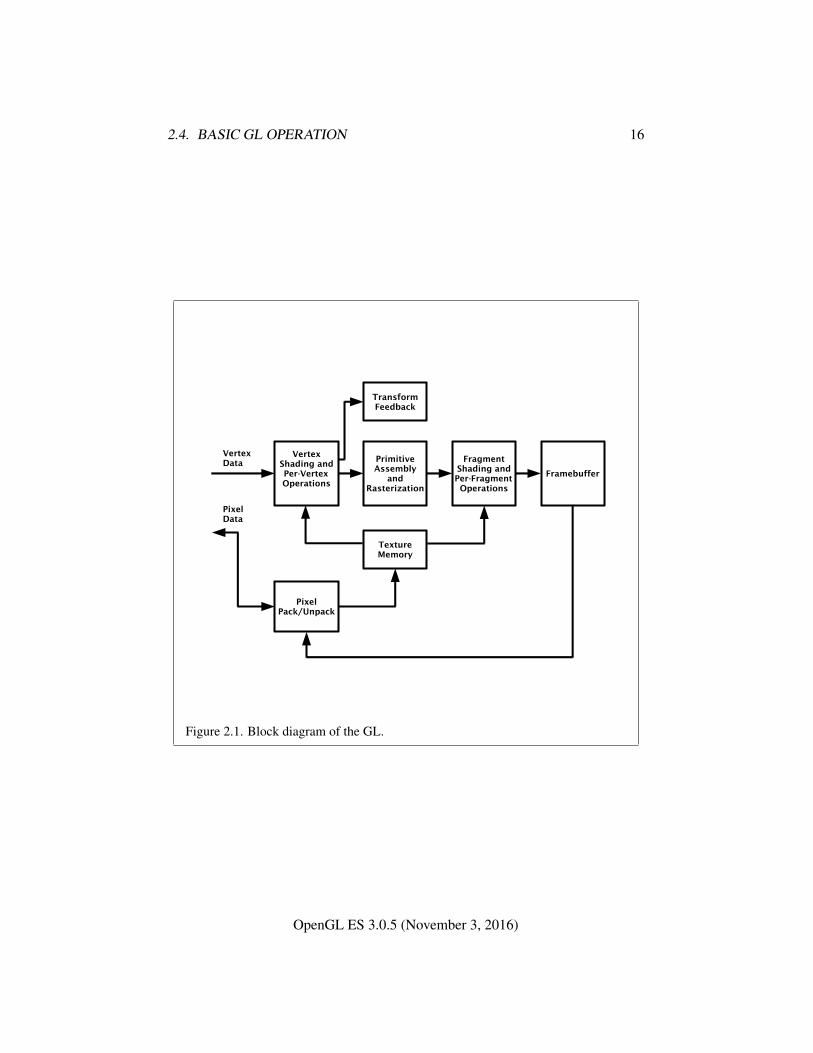
2.4 Basic GL Operation
Figure 2.1 shows a schematic diagram of the GL. Commands enter the GL on theleft. Some commands specify geometric objects to be drawn while others controlhow the objects are handled by the various stages. Commands are effectively sentthrough a processing pipeline.
4Note that OpenGL ES 3.0 uses float where OpenGL ES 2.0 used clampf. Clamping isnow explicitly specified to occur only where and when appropriate, retaining proper clamping inconjunction with fixed-point framebuffers. Because clampf and float are both defined as thesame floating-point type, this change should not introduce compatibility obstacles.
OpenGL ES 3.0.5 (November 3, 2016)
2.4. BASIC GL OPERATION 15
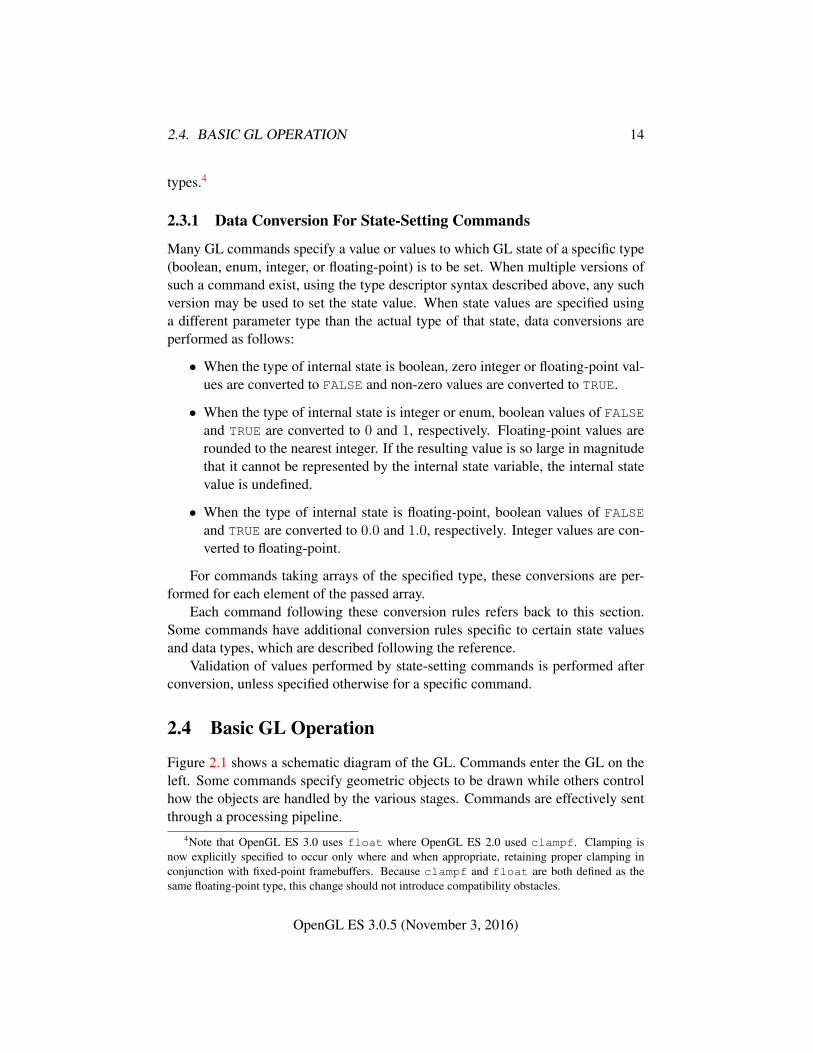
GL Type Minimum DescriptionBit Width
boolean 1 Booleanbyte 8 Signed two’s complement binary inte-
gerubyte 8 Unsigned binary integerchar 8 Characters making up stringsshort 16 Signed two’s complement binary inte-
gerushort 16 Unsigned binary integerint 32 Signed two’s complement binary inte-
geruint 32 Unsigned binary integerint64 64 Signed two’s complement binary inte-
geruint64 64 Unsigned binary integerfixed 32 Signed two’s complement 16.16
scaled integersizei 32 Non-negative binary integer sizeenum 32 Enumerated binary integer valueintptr ptrbits Signed two’s complement binary inte-
gersizeiptr ptrbits Non-negative binary integer sizesync ptrbits Sync object handle (see section 5.2)bitfield 32 Bit fieldhalf 16 Half-precision floating-point value
encoded in an unsigned scalarfloat 32 Floating-point valueclampf 32 Floating-point value clamped to [0, 1]
Table 2.2: GL data types. GL types are not C types. Thus, for example, GLtype int is referred to as GLint outside this document, and is not necessarilyequivalent to the C type int. An implementation may use more bits than thenumber indicated in the table to represent a GL type. Correct interpretation ofinteger values outside the minimum range is not required, however.ptrbits is the number of bits required to represent a pointer type; in other words,types intptr, sizeiptr, and sync must be sufficiently large as to store anyaddress.
OpenGL ES 3.0.5 (November 3, 2016)
2.4. BASIC GL OPERATION 16
Figure 2.1. Block diagram of the GL.
OpenGL ES 3.0.5 (November 3, 2016)
2.5. GL ERRORS 17
The first stage operates on geometric primitives described by vertices: points,line segments, and polygons. In this stage vertices may be transformed and lit,followed by assembly into geometric primitives. The final resulting primitives areclipped to a clip volume in preparation for the next stage, rasterization. The raster-izer produces a series of framebuffer addresses and values using a two-dimensionaldescription of a point, line segment, or polygon. Each fragment so produced is fedto the next stage that performs operations on individual fragments before they fi-nally alter the framebuffer. These operations include conditional updates into theframebuffer based on incoming and previously stored depth values (to effect depthbuffering), blending of incoming fragment colors with stored colors, as well asmasking.
Finally, values may also be read back from the framebuffer. These transfersmay include some type of decoding or encoding.
This ordering is meant only as a tool for describing the GL, not as a strict ruleof how the GL is implemented, and we present it only as a means to organize thevarious operations of the GL.
2.5 GL Errors
The GL detects only a subset of those conditions that could be considered errors.This is because in many cases error checking would adversely impact the perfor-mance of an error-free program.
The command
enum GetError( void );
is used to obtain error information. Each detectable error is assigned a numericcode. When an error is detected, a flag is set and the code is recorded. Furthererrors, if they occur, do not affect this recorded code. When GetError is called,the code is returned and the flag is cleared, so that a further error will again recordits code. If a call to GetError returns NO_ERROR, then there has been no detectableerror since the last call to GetError (or since the GL was initialized).
To allow for distributed implementations, there may be several flag-code pairs.In this case, after a call to GetError returns a value other than NO_ERROR eachsubsequent call returns the non-zero code of a distinct flag-code pair (in unspecifiedorder), until all non-NO_ERROR codes have been returned. When there are no morenon-NO_ERROR error codes, all flags are reset. This scheme requires some positivenumber of pairs of a flag bit and an integer. The initial state of all flags is clearedand the initial value of all codes is NO_ERROR.
OpenGL ES 3.0.5 (November 3, 2016)
2.5. GL ERRORS 18
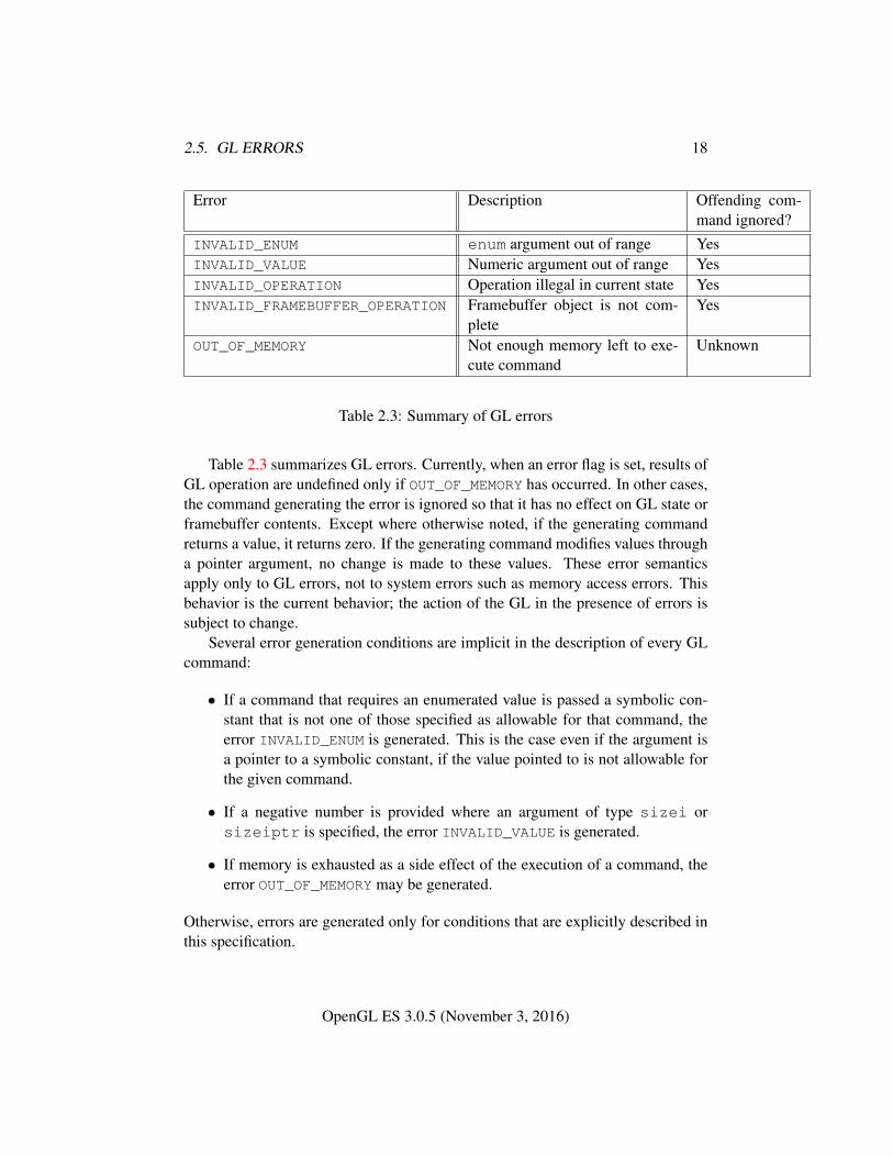
Error Description Offending com-mand ignored?
INVALID_ENUM enum argument out of range YesINVALID_VALUE Numeric argument out of range YesINVALID_OPERATION Operation illegal in current state YesINVALID_FRAMEBUFFER_OPERATION Framebuffer object is not com-
pleteYes
OUT_OF_MEMORY Not enough memory left to exe-cute command
Unknown
Table 2.3: Summary of GL errors
Table 2.3 summarizes GL errors. Currently, when an error flag is set, results ofGL operation are undefined only if OUT_OF_MEMORY has occurred. In other cases,the command generating the error is ignored so that it has no effect on GL state orframebuffer contents. Except where otherwise noted, if the generating commandreturns a value, it returns zero. If the generating command modifies values througha pointer argument, no change is made to these values. These error semanticsapply only to GL errors, not to system errors such as memory access errors. Thisbehavior is the current behavior; the action of the GL in the presence of errors issubject to change.
Several error generation conditions are implicit in the description of every GLcommand:
• If a command that requires an enumerated value is passed a symbolic con-stant that is not one of those specified as allowable for that command, theerror INVALID_ENUM is generated. This is the case even if the argument isa pointer to a symbolic constant, if the value pointed to is not allowable forthe given command.
• If a negative number is provided where an argument of type sizei orsizeiptr is specified, the error INVALID_VALUE is generated.
• If memory is exhausted as a side effect of the execution of a command, theerror OUT_OF_MEMORY may be generated.
Otherwise, errors are generated only for conditions that are explicitly described inthis specification.
OpenGL ES 3.0.5 (November 3, 2016)
2.6. RENDERING COMMANDS 19
2.6 Rendering Commands
GL commands performing rendering into a framebuffer are called rendering com-mands, and include the drawing commands Draw* (see section 2.9.3), as well asthese additional commands:
• BlitFramebuffer (see section 4.3.3)
• Clear (see section 4.2.3)
• ClearBuffer* (see section 4.2.3)
2.7 Primitives and Vertices
In the GL, most geometric objects are drawn by specifying a series of genericattribute sets using DrawArrays or one of the other drawing commands definedin section 2.9.3. Points, lines, polygons, and a variety of related geometric objects(see section 2.7.1) can be drawn in this way.
Each vertex is specified with one or more generic vertex attributes. Each at-tribute is specified with one, two, three, or four scalar values. Generic vertex at-tributes can be accessed from within vertex shaders (section 2.12) and used tocompute values for consumption by later processing stages.
The methods by which generic attributes are sent to the GL, as well as howattributes are used by vertex shaders to generate vertices mapped to the two-dimensional screen, are discussed later.
Before vertex shader execution, the state required by a vertex is its genericvertex attributes. Vertex shader execution processes vertices producing a homoge-neous vertex position and any outputs explicitly written by the vertex shader.
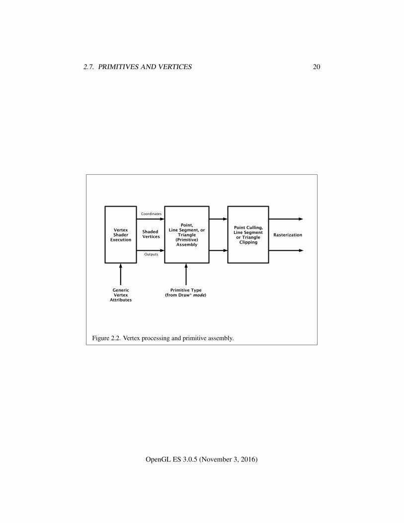
Figure 2.2 shows the sequence of operations that builds a primitive (point, linesegment, or polygon) from a sequence of vertices. After a primitive is formed, it isclipped to a clip volume. This may alter the primitive by altering vertex coordinatesand vertex shader outputs. In the case of line and polygon primitives, clippingmay insert new vertices into the primitive. The vertices defining a primitive to berasterized have outputs associated with them.
2.7.1 Primitive Types
A sequence of vertices is passed to the GL using DrawArrays or one of the otherdrawing commands defined in section 2.9.3. There is no limit to the number ofvertices that may be specified, other than the size of the vertex arrays. The mode
OpenGL ES 3.0.5 (November 3, 2016)
2.7. PRIMITIVES AND VERTICES 20
Figure 2.2. Vertex processing and primitive assembly.
OpenGL ES 3.0.5 (November 3, 2016)
2.7. PRIMITIVES AND VERTICES 21
parameter of these commands determines the type of primitives to be drawn usingthe vertices. The types, and the corresponding mode parameters, are:
PointsA series of individual points may be specified with mode POINTS. Each vertex
defines a separate point.
Line StripsA series of one or more connected line segments may be specified with mode
LINE_STRIP. In this case, the first vertex specifies the first segment’s start pointwhile the second vertex specifies the first segment’s endpoint and the second seg-ment’s start point. In general, the ith vertex (for i > 1) specifies the beginning ofthe ith segment and the end of the i − 1st. The last vertex specifies the end of thelast segment. If only one vertex is specified, then no primitive is generated.
The required state consists of the processed vertex produced from the last ver-tex that was sent (so that a line segment can be generated from it to the currentvertex), and a boolean flag indicating if the current vertex is the first vertex.
Line LoopsLine loops may be specified with mode LINE_LOOP. Loops are the same as
line strips except that a final segment is added from the final specified vertex to thefirst vertex. The required state consists of the processed first vertex, in addition tothe state required for line strips.
Separate LinesIndividual line segments, each specified by a pair of vertices, may be speci-
fied with mode LINES. The first two vertices passed define the first segment, withsubsequent pairs of vertices each defining one more segment. If the number ofspecified vertices is odd, then the last one is ignored. The state required is the sameas for line strips but it is used differently: a processed vertex holding the first vertexof the current segment, and a boolean flag indicating whether the current vertex isodd or even (a segment start or end).
Triangle StripsA triangle strip is a series of triangles connected along shared edges, and may
be specified with mode TRIANGLE_STRIP. In this case, the first three verticesdefine the first triangle (and their order is significant). Each subsequent vertexdefines a new triangle using that point along with two vertices from the previoustriangle. If fewer than three vertices are specified, no primitive is produced. Seefigure 2.3.
OpenGL ES 3.0.5 (November 3, 2016)
2.7. PRIMITIVES AND VERTICES 22
(a) (b) (c)
1
2
3
4
5 1
23
4
51
2
3
4
5
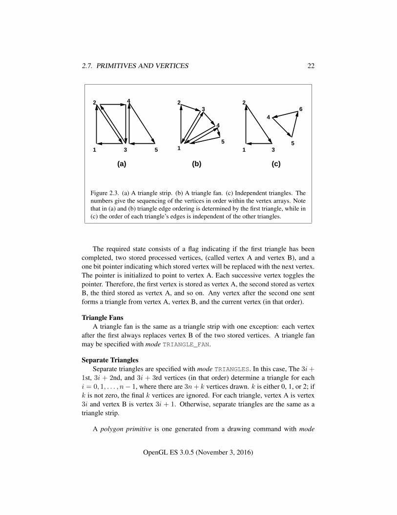
6
Figure 2.3. (a) A triangle strip. (b) A triangle fan. (c) Independent triangles. Thenumbers give the sequencing of the vertices in order within the vertex arrays. Notethat in (a) and (b) triangle edge ordering is determined by the first triangle, while in(c) the order of each triangle’s edges is independent of the other triangles.
The required state consists of a flag indicating if the first triangle has beencompleted, two stored processed vertices, (called vertex A and vertex B), and aone bit pointer indicating which stored vertex will be replaced with the next vertex.The pointer is initialized to point to vertex A. Each successive vertex toggles thepointer. Therefore, the first vertex is stored as vertex A, the second stored as vertexB, the third stored as vertex A, and so on. Any vertex after the second one sentforms a triangle from vertex A, vertex B, and the current vertex (in that order).
Triangle FansA triangle fan is the same as a triangle strip with one exception: each vertex
after the first always replaces vertex B of the two stored vertices. A triangle fanmay be specified with mode TRIANGLE_FAN.
Separate TrianglesSeparate triangles are specified with mode TRIANGLES. In this case, The 3i+
1st, 3i + 2nd, and 3i + 3rd vertices (in that order) determine a triangle for eachi = 0, 1, . . . , n− 1, where there are 3n+ k vertices drawn. k is either 0, 1, or 2; ifk is not zero, the final k vertices are ignored. For each triangle, vertex A is vertex3i and vertex B is vertex 3i + 1. Otherwise, separate triangles are the same as atriangle strip.
A polygon primitive is one generated from a drawing command with mode
OpenGL ES 3.0.5 (November 3, 2016)
2.8. VERTEX SPECIFICATION 23
TRIANGLE_FAN, TRIANGLE_STRIP or TRIANGLES.
2.8 Vertex Specification
Vertex shaders (see section 2.12) access an array of 4-component generic vertexattributes. The first slot of this array is numbered 0, and the size of the array isspecified by the implementation-dependent constant MAX_VERTEX_ATTRIBS.
Current generic attribute values define generic attributes for a vertex when avertex array defining that data is not enabled, as described in section 2.9. The cur-rent values of a generic shader attribute declared as a floating-point scalar, vector,or matrix may be changed at any time by issuing one of the commands
void VertexAttrib{1234}f( uint index,float values );void VertexAttrib{1234}fv( uint index,const float
*values );
These commands specify values that are converted directly to the internalfloating-point representation.
The resulting value(s) are loaded into the generic attribute at slot index, whosecomponents are named x, y, z, and w. The VertexAttrib1* family of commandssets the x coordinate to the provided single argument while setting y and z to 0 andw to 1. Similarly, VertexAttrib2* commands set x and y to the specified values,z to 0 and w to 1; VertexAttrib3* commands set x, y, and z, with w set to 1, andVertexAttrib4* commands set all four coordinates.
The VertexAttrib* entry points may also be used to load shader attributes de-clared as a floating-point matrix. Each column of a matrix takes up one generic4-component attribute slot out of the MAX_VERTEX_ATTRIBS available slots. Ma-trices are loaded into these slots in column major order. Matrix columns are loadedin increasing slot numbers.
The resulting attribute values are undefined if the base type of the shader at-tribute at slot index is not floating-point (e.g. is signed or unsigned integer). Toload current values of a generic shader attribute declared as a signed or unsignedscalar or vector, use the commands
void VertexAttribI4{i ui}( uint index, T values );void VertexAttribI4{i ui}v( uint index, const T values );
These commands specify full signed or unsigned integer values that are loadedinto the generic attribute at slot index in the same fashion as described above.
OpenGL ES 3.0.5 (November 3, 2016)
2.9. VERTEX ARRAYS 24
The resulting attribute values are undefined if the base type of the shader at-tribute at slot index is floating-point; if the base type is integer and unsigned in-teger values are supplied (the VertexAttribI4ui* commands); or if the base typeis unsigned integer and signed integer values are supplied (the VertexAttribI4i*commands)
The error INVALID_VALUE is generated by VertexAttrib* if index is greaterthan or equal to MAX_VERTEX_ATTRIBS.
The state required to support vertex specification consists of the value of MAX_-VERTEX_ATTRIBS four-component vectors to store generic vertex attributes.
The initial values for all generic vertex attributes are (0.0, 0.0, 0.0, 1.0).
2.9 Vertex Arrays
Vertex data are placed into arrays that are stored in the client’s address space (de-scribed here) or in the server’s address space (described in section 2.10). Blocksof data in these arrays may then be used to specify multiple geometric primitivesthrough the execution of a single GL command. The client may specify up tothe value of MAX_VERTEX_ATTRIBS arrays to store one or more generic vertexattributes. The commands
void VertexAttribPointer( uint index, int size, enum type,boolean normalized, sizei stride, constvoid *pointer );
void VertexAttribIPointer( uint index, int size, enum type,sizei stride, const void *pointer );
describe the locations and organizations of these arrays. For each command, typespecifies the data type of the values stored in the array. size indicates the number ofvalues per vertex that are stored in the array. Table 2.4 indicates the allowable val-ues for size and type. For type the values BYTE, SHORT, INT, FIXED, FLOAT, andHALF_FLOAT indicate types byte, short, int, fixed, float, and half, re-spectively; the values UNSIGNED_BYTE, UNSIGNED_SHORT, and UNSIGNED_INT
indicate types ubyte, ushort, and uint, respectively; and the values INT_-2_10_10_10_REV and UNSIGNED_INT_2_10_10_10_REV indicate respectivelyfour signed or unsigned elements packed into a single uint. Both correspond tothe term packed in that table.
An INVALID_VALUE error is generated if size is not one of the values allowedin table 2.4 for the corresponding command.
An INVALID_OPERATION error is generated under any of the following con-ditions:
OpenGL ES 3.0.5 (November 3, 2016)

2.9. VERTEX ARRAYS 25
IntegerCommand Sizes Handling TypesVertexAttribPointer 1, 2, 3, 4 flag byte, ubyte, short,
ushort, int, uint,fixed, float, half,packed
VertexAttribIPointer 1, 2, 3, 4 integer byte, ubyte, short,ushort, int, uint
Table 2.4: Vertex array sizes (values per vertex) and data types. The “Integer Han-dling” column indicates how fixed-point data types are handled: “integer” meansthat they remain as integer values, and “flag” means that they are either convertedto floating-point directly, or converted by normalizing to [0, 1] (for unsigned types)or [−1, 1] (for signed types), depending on the setting of the normalized flag inVertexAttribPointer. packed is not a GL type, but indicates commands acceptingmultiple components packed into a single uint.
• type is INT_2_10_10_10_REV or UNSIGNED_INT_2_10_10_10_REV,and size is not 4;
• VertexAttribPointer or VertexAttribIPointe is called while a non-zero ver-tex array object is bound (see section 2.11), zero is bound to the ARRAY_-
BUFFER buffer object binding point (see section 2.10.6), and the pointer ar-gument is not NULL5.
The index parameter in the VertexAttribPointer and VertexAttribIPointercommands identifies the generic vertex attribute array being described. The er-ror INVALID_VALUE is generated if index is greater than or equal to the valueof MAX_VERTEX_ATTRIBS. Generic attribute arrays with integer type argumentscan be handled in one of three ways: converted to float by normalizing to [0, 1]or [−1, 1] as described in equations 2.1 and 2.2, respectively; converted directlyto float; or left as integers. Integer data for an array specified by VertexAttrib-Pointer will be converted to floating-point by normalizing if normalized is TRUE,and converted directly to floating-point otherwise. The normalized flag is ignoredif type is FIXED, FLOAT, or HALF_FLOAT. Data for an array specified by Vertex-AttribIPointer will always be left as integer values; such data are referred to aspure integers.
5 This error makes it impossible to create a vertex array object containing client array pointers,while still allowing buffer objects to be unbound.
OpenGL ES 3.0.5 (November 3, 2016)
2.9. VERTEX ARRAYS 26
The one, two, three, or four values in an array that correspond to a single vertexcomprise an array element. The values within each array element are stored se-quentially in memory. If stride is specified as zero, then array elements are storedsequentially as well. The error INVALID_VALUE is generated if stride is negative.Otherwise pointers to the ith and (i + 1)st elements of an array differ by stridebasic machine units (typically unsigned bytes), the pointer to the (i+ 1)st elementbeing greater. For each command, pointer specifies the location in memory of thefirst value of the first element of the array being specified.
When values for a vertex shader attribute variable are sourced from an enabledgeneric vertex attribute array, the array must be specified by a command compat-ible with the data type of the variable. The values loaded into a shader attributevariable bound to generic attribute index are undefined if the array for index wasnot specified by:
• VertexAttribPointer, for floating-point base type attributes;
• VertexAttribIPointer with type BYTE, SHORT, or INT for signed integerbase type attributes; or
• VertexAttribIPointer with type UNSIGNED_BYTE, UNSIGNED_SHORT, orUNSIGNED_INT for unsigned integer base type attributes.
An individual generic vertex attribute array is enabled or disabled by callingone of
void EnableVertexAttribArray( uint index );void DisableVertexAttribArray( uint index );
where index identifies the generic vertex attribute array to enable or disable. Theerror INVALID_VALUE is generated if index is greater than or equal to the value ofMAX_VERTEX_ATTRIBS.
The command
void VertexAttribDivisor( uint index, uint divisor );
modifies the rate at which generic vertex attributes advance, which is useful whenrendering multiple instances of primitives in a single draw cal (see DrawArraysIn-stanced and DrawElementsInstanced in section 2.9.3). If divisor is zero, the at-tribute at slot index advances once per vertex. If divisor is non-zero, the attributeadvances once per divisor instances of the primitives being rendered. An attributeis referred to as instanced if its divisor value is non-zero.
An INVALID_VALUE error is generated if index is greater than or equal to thevalue of MAX_VERTEX_ATTRIBS.
OpenGL ES 3.0.5 (November 3, 2016)
2.9. VERTEX ARRAYS 27
2.9.1 Transferring Array Elements
When an array element i is transferred to the GL by DrawArrays, DrawElements,or the other Draw* commands described below, each generic attribute is expandedto four components. If size is one then the x component of the attribute is specifiedby the array. If size is two then the x and y components of the attribute are specifiedby the array. If size is three then x, y, and z are specified by the array. If size is fourthen all components are specified by the array. Unspecified y and z componentsare implicitly set to 0.0 for floating-point array types and 0 for integer array types.Unspecified w components are implicitly set to 1.0 for floating-point array typesand 1 for integer array types.
Primitive restarting is enabled or disabled by calling one of the commands
void Enable( enum target );
and
void Disable( enum target );
with target PRIMITIVE_RESTART_FIXED_INDEX.When DrawElements, DrawElementsInstanced, or DrawRangeElements
transfers a set of generic attribute array elements to the GL, if the index withinthe vertex arrays corresponding to that set is equal to 2N − 1, where N is 8, 16or 32 if the type is UNSIGNED_BYTE, UNSIGNED_SHORT, or UNSIGNED_INT, re-spectively, then the GL does not process those elements as a vertex. Instead, it isas if the drawing command ended with the immediately preceding transfer, and an-other drawing command is immediately started with the same parameters, but onlytransferring the immediately following element through the end of the originallyspecified elements.
2.9.2 Packed Vertex Data Formats
UNSIGNED_INT_2_10_10_10_REV and INT_2_10_10_10_REV vertex data for-mats describe packed, 4 component formats stored in a single 32-bit word.
For the UNSIGNED_INT_2_10_10_10_REV vertex data format, the first (x),second (y), and third (z) components are represented as 10-bit unsigned integervalues and the fourth (w) component is represented as a 2-bit unsigned integervalue.
For the INT_2_10_10_10_REV vertex data format, the x, y and z compo-nents are represented as 10-bit signed two’s complement integer values and the wcomponent is represented as a 2-bit signed two’s complement integer value.
OpenGL ES 3.0.5 (November 3, 2016)
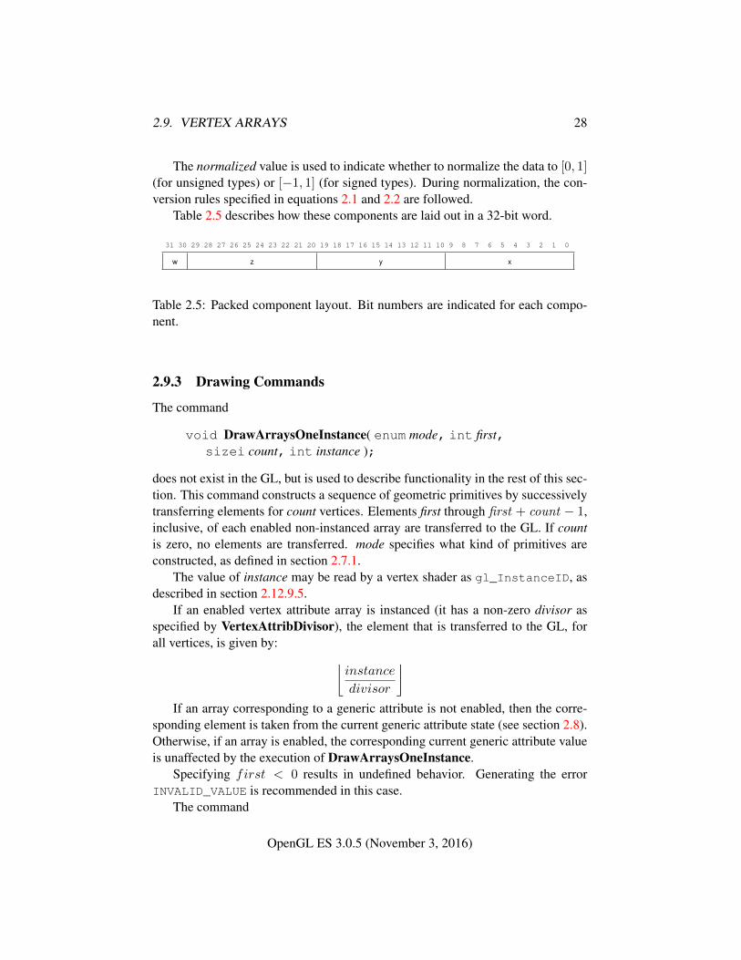
2.9. VERTEX ARRAYS 28
The normalized value is used to indicate whether to normalize the data to [0, 1](for unsigned types) or [−1, 1] (for signed types). During normalization, the con-version rules specified in equations 2.1 and 2.2 are followed.
Table 2.5 describes how these components are laid out in a 32-bit word.
31 30 29 28 27 26 25 24 23 22 21 20 19 18 17 16 15 14 13 12 11 10 9 8 7 6 5 4 3 2 1 0
w z y x
Table 2.5: Packed component layout. Bit numbers are indicated for each compo-nent.
2.9.3 Drawing Commands
The command
void DrawArraysOneInstance( enum mode, int first,sizei count, int instance );
does not exist in the GL, but is used to describe functionality in the rest of this sec-tion. This command constructs a sequence of geometric primitives by successivelytransferring elements for count vertices. Elements first through first + count − 1,inclusive, of each enabled non-instanced array are transferred to the GL. If countis zero, no elements are transferred. mode specifies what kind of primitives areconstructed, as defined in section 2.7.1.
The value of instance may be read by a vertex shader as gl_InstanceID, asdescribed in section 2.12.9.5.
If an enabled vertex attribute array is instanced (it has a non-zero divisor asspecified by VertexAttribDivisor), the element that is transferred to the GL, forall vertices, is given by: ⌊
instance
divisor
⌋If an array corresponding to a generic attribute is not enabled, then the corre-
sponding element is taken from the current generic attribute state (see section 2.8).Otherwise, if an array is enabled, the corresponding current generic attribute valueis unaffected by the execution of DrawArraysOneInstance.
Specifying first < 0 results in undefined behavior. Generating the errorINVALID_VALUE is recommended in this case.
The command
OpenGL ES 3.0.5 (November 3, 2016)
2.9. VERTEX ARRAYS 29
void DrawArrays( enum mode, int first, sizei count );
is equivalent to the command sequence
DrawArraysOneInstance(mode, first, count, 0);
The command
void DrawArraysInstanced( enum mode, int first,sizei count, sizei instanceCount );
behaves identically to DrawArrays except that instanceCount instances of therange of elements are executed and the value of instance advances for each it-eration. Those attributes that have non-zero values for divisor, as specified byVertexAttribDivisor, advance once every divisor instances. It has the same effectas:
if (mode, count, or instanceCount is invalid)generate appropriate error
else {for (i = 0; i < instanceCount; i++) {
DrawArraysOneInstance(mode, first, count, i);}
}
The command
void DrawElementsOneInstance( enum mode, sizei count,enum type, const void *indices, int instance );
does not exist in the GL, but is used to describe functionality in the rest of thissection. This command constructs a sequence of geometric primitives by suc-cessively transferring elements for count vertices. The ith element transferred byDrawElementsOneInstance will be taken from element indices[i] of each en-abled non-instanced array, where indices specifies the location in memory of thefirst index of the element array being specified. type must be one of UNSIGNED_-BYTE, UNSIGNED_SHORT, or UNSIGNED_INT, indicating that the index values areof GL type ubyte, ushort, or uint respectively. mode specifies what kind ofprimitives are constructed, as defined in section 2.7.1.
The value of instance may be read by a vertex shader as gl_InstanceID, asdescribed in section 2.12.9.5.
OpenGL ES 3.0.5 (November 3, 2016)
2.9. VERTEX ARRAYS 30
If an enabled vertex attribute array is instanced (it has a non-zero divisor asspecified by VertexAttribDivisor), the element that is transferred to the GL, forall vertices, is given by: ⌊
instance
divisor
⌋If type is UNSIGNED_INT, an implementation may restrict the maximum value
that can be used as an index to less than the maximum value that can be repre-sented by the uint type. The maximum value supported by an implementationmay be queried by calling GetInteger64v with pname MAX_ELEMENT_INDEX.Using an index value greater than MAX_ELEMENT_INDEX will result in undefinedimplementation-dependent behavior, unless primitive restart is enabled (see sec-tion 2.9.1) and the index value is 232 − 1.
If an array corresponding to a generic attribute is not enabled, then the corre-sponding element is taken from the current generic attribute state (see section 2.8).Otherwise, if an array is enabled, the corresponding current generic attribute valueis unaffected by the execution of DrawElementsOneInstance.
The command
void DrawElements( enum mode, sizei count, enum type,const void *indices );
behaves identically to DrawElementsOneInstance with the instance parameterset to zero; the effect of calling
DrawElements(mode, count, type, indices);
is equivalent to the command sequence:
if (mode, count or type is invalid)generate appropriate error
elseDrawElementsOneInstance(mode, count, type, indices, 0);
The command
void DrawElementsInstanced( enum mode, sizei count,enum type, const void *indices, sizei instanceCount );
behaves identically to DrawElements except that instanceCount instances of theset of elements are executed and the value of instance advances between each set.Instanced attributes are advanced as they do during execution of DrawArraysIn-stanced. It has the same effect as:
OpenGL ES 3.0.5 (November 3, 2016)
2.9. VERTEX ARRAYS 31
if (mode, count, instanceCount, or type is invalid)generate appropriate error
else {for (int i = 0; i < instanceCount; i++) {
DrawElementsOneInstance(mode, count, type, indices, i);}
}
The command
void DrawRangeElements( enum mode, uint start,uint end, sizei count, enum type, constvoid *indices );
is a restricted form of DrawElements. mode, count, type, and indices match thecorresponding arguments to DrawElements, with the additional constraint that allindex values identified by indices must lie between start and end inclusive.
Implementations denote recommended maximum amounts of vertex and indexdata, which may be queried by calling GetIntegerv with the symbolic constantsMAX_ELEMENTS_VERTICES and MAX_ELEMENTS_INDICES. If end − start + 1is greater than the value of MAX_ELEMENTS_VERTICES, or if count is greater thanthe value of MAX_ELEMENTS_INDICES, then the call may operate at reduced per-formance. There is no requirement that all vertices in the range [start, end] bereferenced. However, the implementation may partially process unused vertices,reducing performance from what could be achieved with an optimal index set.
The error INVALID_VALUE is generated if end < start. Invalid mode, count,or type parameters generate the same errors as would the corresponding call toDrawElements. It is an error for index values (other than the primitive restartindex when primitive restart is enabled) to lie outside the range [start, end],but implementations are not required to check for this. Such indices will causeimplementation-dependent behavior.
If the number of supported generic vertex attributes (the value of MAX_-
VERTEX_ATTRIBS) is n, then the state required to implement vertex arrays con-sists of n boolean values, n memory pointers, n integer stride values, n symbolicconstants representing array types, n integers representing values per element, nboolean values indicating normalization, n boolean values indicating whether theattribute values are pure integers, and n integers representing vertex attribute divi-sors.
In the initial state, the boolean values are each false, the memory pointers areeach NULL, the strides are each zero, the array types are each FLOAT, the integers
OpenGL ES 3.0.5 (November 3, 2016)
2.10. BUFFER OBJECTS 32
representing values per element are each four, the normalized and pure integer flagsare each false, and the divisors are each zero.
2.10 Buffer Objects
The GL uses many types of data supplied by the client. Some of this data must bestored in server memory, and it is usually desirable to store other types of frequentlyused client data, such as vertex array and pixel data, in server memory even if theoption to store it in client memory exists. Buffer objects provide a mechanismto allocate, initialize, and render from such memory. The name space for bufferobjects is the unsigned integers, with zero reserved for the GL.
The command
void GenBuffers( sizei n, uint *buffers );
returns n previously unused buffer object names in buffers. These names aremarked as used, for the purposes of GenBuffers only, but they do not acquirebuffer state until they are first bound with BindBuffer (see below), just as if theywere unused.
Buffer objects are deleted by calling
void DeleteBuffers( sizei n, const uint *buffers );
buffers contains n names of buffer objects to be deleted. After a buffer object isdeleted it has no contents, and its name is again unused. If any portion of a bufferobject being deleted is mapped in the current context or any context current toanother thread, it is as though UnmapBuffer (see section 2.10.3) is executed ineach such context prior to deleting the data store of the buffer.
Unused names in buffers that have been marked as used for the purposes ofGenBuffers are marked as unused again. Unused names in buffers are silentlyignored, as is the value zero.
2.10.1 Creating and Binding Buffer Objects
A buffer object is created by binding an unused name to a buffer target. The bindingis effected by calling
void BindBuffer( enum target, uint buffer );
OpenGL ES 3.0.5 (November 3, 2016)
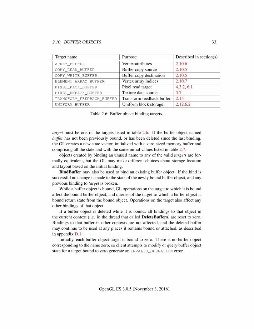
2.10. BUFFER OBJECTS 33
Target name Purpose Described in section(s)ARRAY_BUFFER Vertex attributes 2.10.6COPY_READ_BUFFER Buffer copy source 2.10.5COPY_WRITE_BUFFER Buffer copy destination 2.10.5ELEMENT_ARRAY_BUFFER Vertex array indices 2.10.7PIXEL_PACK_BUFFER Pixel read target 4.3.2, 6.1PIXEL_UNPACK_BUFFER Texture data source 3.7TRANSFORM_FEEDBACK_BUFFER Transform feedback buffer 2.15UNIFORM_BUFFER Uniform block storage 2.12.6.2
Table 2.6: Buffer object binding targets.
target must be one of the targets listed in table 2.6. If the buffer object namedbuffer has not been previously bound, or has been deleted since the last binding,the GL creates a new state vector, initialized with a zero-sized memory buffer andcomprising all the state and with the same initial values listed in table 2.7.
objects created by binding an unused name to any of the valid targets are for-mally equivalent, but the GL may make different choices about storage locationand layout based on the initial binding.
BindBuffer may also be used to bind an existing buffer object. If the bind issuccessful no change is made to the state of the newly bound buffer object, and anyprevious binding to target is broken.
While a buffer object is bound, GL operations on the target to which it is boundaffect the bound buffer object, and queries of the target to which a buffer object isbound return state from the bound object. Operations on the target also affect anyother bindings of that object.
If a buffer object is deleted while it is bound, all bindings to that object inthe current context (i.e. in the thread that called DeleteBuffers) are reset to zero.Bindings to that buffer in other contexts are not affected, and the deleted buffermay continue to be used at any places it remains bound or attached, as describedin appendix D.1.
Initially, each buffer object target is bound to zero. There is no buffer objectcorresponding to the name zero, so client attempts to modify or query buffer objectstate for a target bound to zero generate an INVALID_OPERATION error.
OpenGL ES 3.0.5 (November 3, 2016)
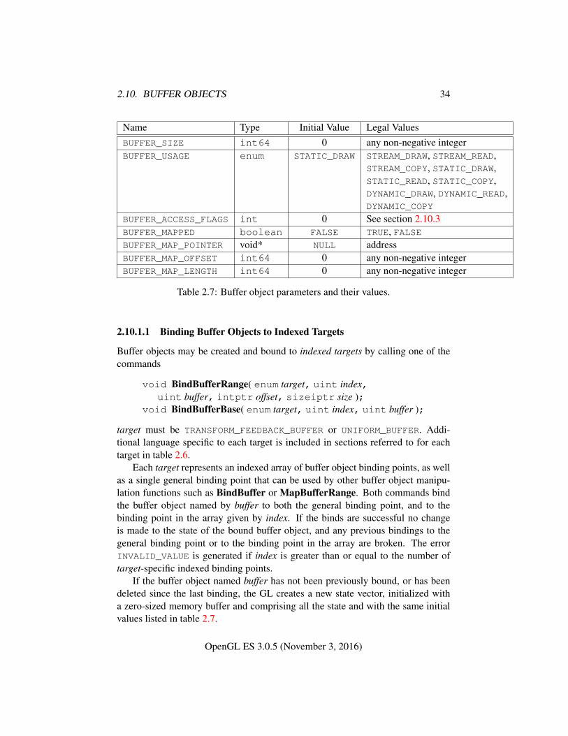
2.10. BUFFER OBJECTS 34
Name Type Initial Value Legal ValuesBUFFER_SIZE int64 0 any non-negative integerBUFFER_USAGE enum STATIC_DRAW STREAM_DRAW, STREAM_READ,
STREAM_COPY, STATIC_DRAW,STATIC_READ, STATIC_COPY,DYNAMIC_DRAW, DYNAMIC_READ,DYNAMIC_COPY
BUFFER_ACCESS_FLAGS int 0 See section 2.10.3BUFFER_MAPPED boolean FALSE TRUE, FALSEBUFFER_MAP_POINTER void* NULL addressBUFFER_MAP_OFFSET int64 0 any non-negative integerBUFFER_MAP_LENGTH int64 0 any non-negative integer
Table 2.7: Buffer object parameters and their values.
2.10.1.1 Binding Buffer Objects to Indexed Targets
Buffer objects may be created and bound to indexed targets by calling one of thecommands
void BindBufferRange( enum target, uint index,uint buffer, intptr offset, sizeiptr size );
void BindBufferBase( enum target, uint index, uint buffer );
target must be TRANSFORM_FEEDBACK_BUFFER or UNIFORM_BUFFER. Addi-tional language specific to each target is included in sections referred to for eachtarget in table 2.6.
Each target represents an indexed array of buffer object binding points, as wellas a single general binding point that can be used by other buffer object manipu-lation functions such as BindBuffer or MapBufferRange. Both commands bindthe buffer object named by buffer to both the general binding point, and to thebinding point in the array given by index. If the binds are successful no changeis made to the state of the bound buffer object, and any previous bindings to thegeneral binding point or to the binding point in the array are broken. The errorINVALID_VALUE is generated if index is greater than or equal to the number oftarget-specific indexed binding points.
If the buffer object named buffer has not been previously bound, or has beendeleted since the last binding, the GL creates a new state vector, initialized witha zero-sized memory buffer and comprising all the state and with the same initialvalues listed in table 2.7.
OpenGL ES 3.0.5 (November 3, 2016)
2.10. BUFFER OBJECTS 35
For BindBufferRange, offset specifies a starting offset into the buffer objectbuffer, and size specifies the amount of data that can be read from or written tothe buffer object while used as an indexed target. Both offset and size are in basicmachine units. The error INVALID_VALUE is generated if buffer is not zero andsize is less than or equal to zero or if buffer is not zero and offset is negative or offsetor size do not respectively satisfy the constraints described for those parameters forthe specified target, as described in sections 2.12.6 and 2.15.2.
BindBufferBase binds the entire buffer, even when the size of the buffer ischanged after the binding is established. The starting offset is zero, and the amountof data that can be read from or written to the buffer is determined by the size ofthe bound buffer at the time the binding is used.
Regardless of the size specified with BindBufferRange, the GL will never reador write beyond the end of a bound buffer. In some cases this constraint may resultin visibly different behavior when a buffer overflow would otherwise result, suchas described for transform feedback operations in section 2.15.2.
2.10.2 Creating Buffer Object Data Stores
The data store of a buffer object is created and initialized by calling
void BufferData( enum target, sizeiptr size, constvoid *data, enum usage );
with target set to one of the targets listed in table 2.6, size set to the size of the datastore in basic machine units, and data pointing to the source data in client memory.If data is non-NULL, then the source data is copied to the buffer object’s data store.If data is NULL, then the contents of the buffer object’s data store are undefined.
usage is specified as one of nine enumerated values, indicating the expectedapplication usage pattern of the data store. The values are:
STREAM_DRAW The data store contents will be specified once by the application,and used at most a few times as the source for GL drawing and image speci-fication commands.
STREAM_READ The data store contents will be specified once by reading data fromthe GL, and queried at most a few times by the application.
STREAM_COPY The data store contents will be specified once by reading data fromthe GL, and used at most a few times as the source for GL drawing and imagespecification commands.
OpenGL ES 3.0.5 (November 3, 2016)
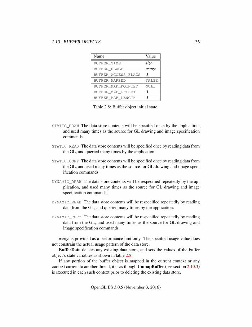
2.10. BUFFER OBJECTS 36
Name ValueBUFFER_SIZE sizeBUFFER_USAGE usageBUFFER_ACCESS_FLAGS 0BUFFER_MAPPED FALSE
BUFFER_MAP_POINTER NULL
BUFFER_MAP_OFFSET 0BUFFER_MAP_LENGTH 0
Table 2.8: Buffer object initial state.
STATIC_DRAW The data store contents will be specified once by the application,and used many times as the source for GL drawing and image specificationcommands.
STATIC_READ The data store contents will be specified once by reading data fromthe GL, and queried many times by the application.
STATIC_COPY The data store contents will be specified once by reading data fromthe GL, and used many times as the source for GL drawing and image spec-ification commands.
DYNAMIC_DRAW The data store contents will be respecified repeatedly by the ap-plication, and used many times as the source for GL drawing and imagespecification commands.
DYNAMIC_READ The data store contents will be respecified repeatedly by readingdata from the GL, and queried many times by the application.
DYNAMIC_COPY The data store contents will be respecified repeatedly by readingdata from the GL, and used many times as the source for GL drawing andimage specification commands.
usage is provided as a performance hint only. The specified usage value doesnot constrain the actual usage pattern of the data store.
BufferData deletes any existing data store, and sets the values of the bufferobject’s state variables as shown in table 2.8.
If any portion of the buffer object is mapped in the current context or anycontext current to another thread, it is as though UnmapBuffer (see section 2.10.3)is executed in each such context prior to deleting the existing data store.
OpenGL ES 3.0.5 (November 3, 2016)
2.10. BUFFER OBJECTS 37
Clients must align data elements consistently with the requirements of theclient platform, with an additional base-level requirement that an offset within abuffer to a datum comprising N basic machine units be a multiple of N .
If the GL is unable to create a data store of the requested size, the error OUT_-OF_MEMORY is generated.
To modify some or all of the data contained in a buffer object’s data store, theclient may use the command
void BufferSubData( enum target, intptr offset,sizeiptr size, const void *data );
with target set to one of the targets listed in table 2.6. offset and size indicate therange of data in the buffer object that is to be replaced, in terms of basic machineunits. data specifies a region of client memory size basic machine units in length,containing the data that replace the specified buffer range. An INVALID_VALUE
error is generated if offset or size is less than zero or if offset + size is greaterthan the value of BUFFER_SIZE. An INVALID_OPERATION error is generated ifany part of the specified buffer range is mapped with MapBufferRange (see sec-tion 2.10.3).
2.10.3 Mapping and Unmapping Buffer Data
All or part of the data store of a buffer object may be mapped into the client’saddress space by calling
void *MapBufferRange( enum target, intptr offset,sizeiptr length, bitfield access );
with target set to one of the targets listed in table 2.6. offset and length indicate therange of data in the buffer object that is to be mapped, in terms of basic machineunits. access is a bitfield containing flags which describe the requested mapping.These flags are described below.
If no error occurs, a pointer to the beginning of the mapped range is returnedonce all pending operations on that buffer have completed, and may be used tomodify and/or query the corresponding range of the buffer, according to the fol-lowing flag bits set in access:
• MAP_READ_BIT indicates that the returned pointer may be used to readbuffer object data. No GL error is generated if the pointer is used to querya mapping which excludes this flag, but the result is undefined and systemerrors (possibly including program termination) may occur.
OpenGL ES 3.0.5 (November 3, 2016)
2.10. BUFFER OBJECTS 38
• MAP_WRITE_BIT indicates that the returned pointer may be used to modifybuffer object data. No GL error is generated if the pointer is used to modifya mapping which excludes this flag, but the result is undefined and systemerrors (possibly including program termination) may occur.
Pointer values returned by MapBufferRange may not be passed as parametervalues to GL commands. For example, they may not be used to specify arraypointers, or to specify or query pixel or texture image data; such actions produceundefined results, although implementations may not check for such behavior forperformance reasons.
Mappings to the data stores of buffer objects may have nonstandard perfor-mance characteristics. For example, such mappings may be marked as uncacheableregions of memory, and in such cases reading from them may be very slow. To en-sure optimal performance, the client should use the mapping in a fashion consistentwith the values of BUFFER_USAGE and access. Using a mapping in a fashion in-consistent with these values is liable to be multiple orders of magnitude slowerthan using normal memory.
The following optional flag bits in access may be used to modify the mapping:
• MAP_INVALIDATE_RANGE_BIT indicates that the previous contents of thespecified range may be discarded. Data within this range are undefined withthe exception of subsequently written data. No GL error is generated if sub-sequent GL operations access unwritten data, but the result is undefined andsystem errors (possibly including program termination) may occur. This flagmay not be used in combination with MAP_READ_BIT.
• MAP_INVALIDATE_BUFFER_BIT indicates that the previous contents of theentire buffer may be discarded. Data within the entire buffer are undefinedwith the exception of subsequently written data. No GL error is generated ifsubsequent GL operations access unwritten data, but the result is undefinedand system errors (possibly including program termination) may occur. Thisflag may not be used in combination with MAP_READ_BIT.
• MAP_FLUSH_EXPLICIT_BIT indicates that one or more discrete subrangesof the mapping may be modified. When this flag is set, modifications toeach subrange must be explicitly flushed by calling FlushMappedBuffer-Range. No GL error is set if a subrange of the mapping is modified andnot flushed, but data within the corresponding subrange of the buffer are un-defined. This flag may only be used in conjunction with MAP_WRITE_BIT.When this option is selected, flushing is strictly limited to regions that are
OpenGL ES 3.0.5 (November 3, 2016)
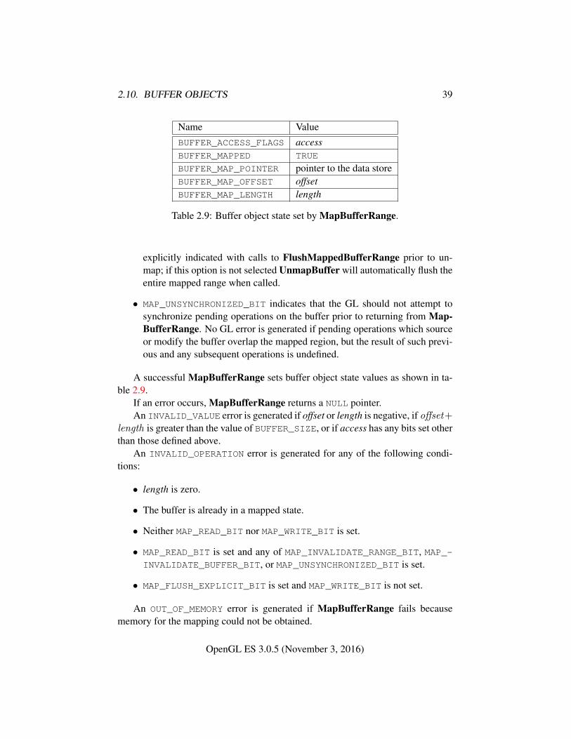
2.10. BUFFER OBJECTS 39
Name ValueBUFFER_ACCESS_FLAGS accessBUFFER_MAPPED TRUE
BUFFER_MAP_POINTER pointer to the data storeBUFFER_MAP_OFFSET offsetBUFFER_MAP_LENGTH length
Table 2.9: Buffer object state set by MapBufferRange.
explicitly indicated with calls to FlushMappedBufferRange prior to un-map; if this option is not selected UnmapBuffer will automatically flush theentire mapped range when called.
• MAP_UNSYNCHRONIZED_BIT indicates that the GL should not attempt tosynchronize pending operations on the buffer prior to returning from Map-BufferRange. No GL error is generated if pending operations which sourceor modify the buffer overlap the mapped region, but the result of such previ-ous and any subsequent operations is undefined.
A successful MapBufferRange sets buffer object state values as shown in ta-ble 2.9.
If an error occurs, MapBufferRange returns a NULL pointer.An INVALID_VALUE error is generated if offset or length is negative, if offset+
length is greater than the value of BUFFER_SIZE, or if access has any bits set otherthan those defined above.
An INVALID_OPERATION error is generated for any of the following condi-tions:
• length is zero.
• The buffer is already in a mapped state.
• Neither MAP_READ_BIT nor MAP_WRITE_BIT is set.
• MAP_READ_BIT is set and any of MAP_INVALIDATE_RANGE_BIT, MAP_-INVALIDATE_BUFFER_BIT, or MAP_UNSYNCHRONIZED_BIT is set.
• MAP_FLUSH_EXPLICIT_BIT is set and MAP_WRITE_BIT is not set.
An OUT_OF_MEMORY error is generated if MapBufferRange fails becausememory for the mapping could not be obtained.
OpenGL ES 3.0.5 (November 3, 2016)
2.10. BUFFER OBJECTS 40
No error is generated if memory outside the mapped range is modified orqueried, but the result is undefined and system errors (possibly including programtermination) may occur.
If a buffer is mapped with the MAP_FLUSH_EXPLICIT_BIT flag, modificationsto the mapped range may be indicated by calling
void FlushMappedBufferRange( enum target, intptr offset,sizeiptr length );
with target set to one of the targets listed in table 2.6. offset and length indi-cate a modified subrange of the mapping, in basic machine units. The specifiedsubrange to flush is relative to the start of the currently mapped range of buffer.FlushMappedBufferRange may be called multiple times to indicate distinct sub-ranges of the mapping which require flushing.
An INVALID_VALUE error is generated if offset or length is negative, or ifoffset + length exceeds the size of the mapping.
An INVALID_OPERATION error is generated if zero is bound to target.An INVALID_OPERATION error is generated if the buffer bound to target is
not mapped, or is mapped without the MAP_FLUSH_EXPLICIT_BIT flag.
2.10.3.1 Unmapping Buffers
After the client has specified the contents of a mapped buffer range, and before thedata in that range are dereferenced by any GL commands, the mapping must berelinquished by calling
boolean UnmapBuffer( enum target );
with target set to one of the targets listed in table 2.6. Unmapping a mapped bufferobject invalidates the pointer to its data store and sets the object’s BUFFER_-
MAPPED, BUFFER_MAP_POINTER, BUFFER_ACCESS_FLAGS, BUFFER_MAP_-
OFFSET, and BUFFER_MAP_LENGTH state variables to the initial values shown intable 2.8.
UnmapBuffer returns TRUE unless data values in the buffer’s data store havebecome corrupted during the period that the buffer was mapped. Such corruptioncan be the result of a screen resolution change or other window system-dependentevent that causes system heaps such as those for high-performance graphics mem-ory to be discarded. GL implementations must guarantee that such corruption canoccur only during the periods that a buffer’s data store is mapped. If such corrup-tion has occurred, UnmapBuffer returns FALSE, and the contents of the buffer’sdata store become undefined.
OpenGL ES 3.0.5 (November 3, 2016)
2.10. BUFFER OBJECTS 41
If the buffer data store is already in the unmapped state, UnmapBuffer returnsFALSE, and an INVALID_OPERATION error is generated.
Buffers are implicitly unmapped as a side effect of deletion or reinitialization(i.e. calling DeleteBuffers or BufferData).
2.10.3.2 Effects of Mapping Buffers on Other GL Commands
Any GL command which attempts to read from, write to, or change the state ofa buffer object may generate an INVALID_OPERATION error if all or part of thebuffer object is mapped. However, only commands which explicitly describe thiserror are required to do so. If an error is not generated, using such commands toperform invalid reads, writes, or state changes will have undefined results and mayresult in GL interruption or termination.
2.10.4 Effects of Accessing Outside Buffer Bounds
Many GL commands generate an INVALID_OPERATION error if the commandattempts to read from or write to a location in a bound buffer object at an offsetless than zero, or greater than or equal to the buffer’s size. Commands that are notspecified to detect these errors are not required to do so, and using such commandsto perform invalid reads or writes will have undefined results, which may includeGL interruption or termination.
2.10.5 Copying Between Buffers
All or part of the data store of a buffer object may be copied to the data store ofanother buffer object by calling
void CopyBufferSubData( enum readtarget, enum writetarget,intptr readoffset, intptr writeoffset, sizeiptr size );
with readtarget and writetarget each set to one of the targets listed in table 2.6.While any of these targets may be used, the COPY_READ_BUFFER and COPY_-
WRITE_BUFFER targets are provided specifically for copies, so that they can bedone without affecting other buffer binding targets that may be in use. writeoffsetand size specify the range of data in the buffer object bound to writetarget that isto be replaced, in terms of basic machine units. readoffset and size specify therange of data in the buffer object bound to readtarget that is to be copied to thecorresponding region of writetarget.
An INVALID_VALUE error is generated if any of readoffset, writeoffset, or sizeare negative, if readoffset + size exceeds the size of the buffer object bound to
OpenGL ES 3.0.5 (November 3, 2016)
2.10. BUFFER OBJECTS 42
readtarget, or if writeoffset + size exceeds the size of the buffer object bound towritetarget.
An INVALID_VALUE error is generated if the same buffer object is bound toboth readtarget and writetarget, and the ranges [readoffset , readoffset + size) and[writeoffset ,writeoffset + size) overlap.
An INVALID_OPERATION error is generated if zero is bound to readtarget orwritetarget.
An INVALID_OPERATION error is generated if the buffer objects bound toeither readtarget or writetarget are mapped.
2.10.6 Vertex Arrays in Buffer Objects
Blocks of vertex array data may be stored in buffer objects with the same formatand layout options supported for client-side vertex arrays. A buffer object bindingpoint is added to the client state associated with each vertex array index. The com-mands that specify the locations and organizations of vertex arrays copy the bufferobject name that is bound to ARRAY_BUFFER to the binding point correspondingto the vertex array of the index being specified. For example, the VertexAttrib-Pointer command copies the value of ARRAY_BUFFER_BINDING (the queriablename of the buffer binding corresponding to the target ARRAY_BUFFER) to theclient state variable VERTEX_ATTRIB_ARRAY_BUFFER_BINDING for the speci-fied index.
Rendering command DrawArrays and the other drawing commands definedin section 2.9.3 operate as previously defined, except that data for enabled genericattribute arrays are sourced from buffers if the array’s buffer binding is non-zero.When an array is sourced from a buffer object, the pointer value of that array isused to compute an offset, in basic machine units, into the data store of the bufferobject. This offset is computed by subtracting a NULL pointer from the pointervalue, where both pointers are treated as pointers to basic machine units.
It is acceptable for generic attribute arrays to be sourced from any combinationof client memory and various buffer objects during a single rendering operation.
2.10.7 Array Indices in Buffer Objects
Blocks of array indices may be stored in buffer objects with the same formatoptions that are supported for client-side index arrays. Initially zero is boundto ELEMENT_ARRAY_BUFFER, indicating that DrawElements, DrawRangeEle-ments, and DrawElementsInstanced are to source their indices from arrayspassed as their indices parameters.
OpenGL ES 3.0.5 (November 3, 2016)
2.11. VERTEX ARRAY OBJECTS 43
A buffer object is bound to ELEMENT_ARRAY_BUFFER by calling BindBufferwith target set to ELEMENT_ARRAY_BUFFER, and buffer set to the name of thebuffer object. If no corresponding buffer object exists, one is initialized as definedin section 2.10.
While a non-zero buffer object name is bound to ELEMENT_ARRAY_BUFFER,DrawElements, DrawRangeElements, and DrawElementsInstanced sourcetheir indices from that buffer object, using their indices parameters as offsets intothe buffer object in the same fashion as described in section 2.10.6.
In some cases performance will be optimized by storing indices and array datain separate buffer objects, and by creating those buffer objects with the correspond-ing binding points.
2.10.8 Buffer Object State
The state required to support buffer objects consists of binding names for eachof the buffer targets in table 2.6, and for each of the indexed buffer targets in sec-tion 2.10.1.1. The state required for index buffer targets for transform feedback anduniform buffer array bindings is summarized in tables 6.24 and 6.25, respectively.
Additionally, each vertex array has an associated binding so there is a bufferobject binding for each of the vertex attribute arrays. The initial values for all bufferobject bindings is zero.
The state of each buffer object consists of a buffer size in basic machine units, ausage parameter, an access parameter, a mapped boolean, two integers for the offsetand size of the mapped region, a pointer to the mapped buffer (NULL if unmapped),and the sized array of basic machine units for the buffer data.
2.11 Vertex Array Objects
The buffer objects that are to be used by the vertex stage of the GL are collectedtogether to form a vertex array object. All state related to the definition of data usedby the vertex processor is encapsulated in a vertex array object. The name spacefor vertex array objects is the unsigned integers, with zero reserved by the GL torepresent the default vertex array object.
The command
void GenVertexArrays( sizei n, uint *arrays );
returns n previously unused vertex array object names in arrays. These namesare marked as used, for the purposes of GenVertexArrays only, but they do notacquire array state until they are first bound.
OpenGL ES 3.0.5 (November 3, 2016)
2.12. VERTEX SHADERS 44
Vertex array objects are deleted by calling
void DeleteVertexArrays( sizei n, const uint *arrays );
arrays contains n names of vertex array objects to be deleted. Once a vertex arrayobject is deleted it has no contents and its name is again unused. If a vertex arrayobject that is currently bound is deleted, the binding for that object reverts to zeroand the default vertex array becomes current. Unused names in arrays that havebeen marked as used for the purposes of GenVertexArrays are marked as unusedagain. Unused names in arrays are silently ignored, as is the value zero.
A vertex array object is created by binding a name returned by GenVertexAr-rays with the command
void BindVertexArray( uint array );
array is the vertex array object name. The resulting vertex array object is a newstate vector, comprising all the state and with the same initial values listed in ta-ble 6.2.
BindVertexArray may also be used to bind an existing vertex array object.If the bind is successful no change is made to the state of the bound vertex arrayobject, and any previous binding is broken.
The currently bound vertex array object is used for all commands which modifyvertex array state, such as VertexAttribPointer and EnableVertexAttribArray;all commands which draw from vertex arrays, such as DrawArrays and DrawEle-ments; and all queries of vertex array state (see chapter 6).
BindVertexArray fails and an INVALID_OPERATION error is generated if ar-ray is not zero or a name returned from a previous call to GenVertexArrays, or ifsuch a name has since been deleted with DeleteVertexArrays.
2.12 Vertex Shaders
Vertex shaders describe the operations that occur on vertex values and their associ-ated data.
A vertex shader is an array of strings containing source code for the operationsthat are meant to occur on each vertex that is processed. The language used forvertex shaders is described in the OpenGL ES Shading Language Specification.
To use a vertex shader, shader source code is first loaded into a shader objectand then compiled. A shader object corresponds to a stage in the rendering pipelinereferred to as its shader stage or type. Alternatively, pre-compiled shader binarycode may be directly loaded into a shader object. A GL implementation must
OpenGL ES 3.0.5 (November 3, 2016)
2.12. VERTEX SHADERS 45
support shader compilation (the boolean value SHADER_COMPILERmust be TRUE).If the integer value of NUM_SHADER_BINARY_FORMATS is greater than zero, thenshader binary loading is supported.
A vertex shader object is attached to a program object. The program object isthen linked, which generates executable code from all the compiled shader objectsattached to the program. Alternatively, pre-compiled program binary code may bedirectly loaded into a program object (see section 2.12.4).
When a linked program object is used as the current program object, the ex-ecutable code for the vertex shader it contains is used to process vertices. If noprogram object is currently in use, the results of vertex shader execution are unde-fined.
In addition to vertex shaders, fragment shaders can be created, compiled, andlinked into program objects. Fragment shaders affect the processing of fragmentsduring rasterization (see section 3.9). A program object must contain both vertexand fragment shaders.
A vertex shader can reference a number of variables as it executes. Vertexattributes are the per-vertex values specified in section 2.8. Uniforms are per-program variables that are constant during program execution. Samplers are aspecial form of uniform used for texturing (section 3.8). Output variables holdthe results of vertex shader execution that are used later in the pipeline. Each ofthese variable types is described in more detail below.
2.12.1 Shader Objects
The source code that makes up a program that gets executed by one of the pro-grammable stages is encapsulated in a shader object.
The name space for shader objects is the unsigned integers, with zero reservedfor the GL. This name space is shared with program objects. The following sectionsdefine commands that operate on shader and program objects by name. Commandsthat accept shader or program object names will generate the error INVALID_-VALUE if the provided name is not the name of either a shader or program objectand INVALID_OPERATION if the provided name identifies an object that is not theexpected type.
To create a shader object, use the command
uint CreateShader( enum type );
The shader object is empty when it is created. The type argument specifies the typeof shader object to be created. For vertex shaders, type must be VERTEX_SHADER.A non-zero name that can be used to reference the shader object is returned. If anerror occurs, zero will be returned.
OpenGL ES 3.0.5 (November 3, 2016)
2.12. VERTEX SHADERS 46
The command
void ShaderSource( uint shader, sizei count, constchar * const *string, const int *length );
loads source code into the shader object named shader. string is an array of countpointers to optionally null-terminated character strings that make up the sourcecode. The length argument is an array with the number of chars in each string (thestring length). If an element in length is negative, its accompanying string is null-terminated. If length is NULL, all strings in the string argument are considered null-terminated. The ShaderSource command sets the source code for the shader tothe text strings in the string array. If shader previously had source code loaded intoit, the existing source code is completely replaced. Any length passed in excludesthe null terminator in its count.
The strings that are loaded into a shader object are expected to form the sourcecode for a valid shader as defined in the OpenGL ES Shading Language Specifica-tion.
Once the source code for a shader has been loaded, a shader object can becompiled with the command
void CompileShader( uint shader );
Each shader object has a boolean status, COMPILE_STATUS, that is modified asa result of compilation. This status can be queried with GetShaderiv (see sec-tion 6.1.12). This status will be set to TRUE if shader was compiled without errorsand is ready for use, and FALSE otherwise. Compilation can fail for a variety ofreasons as listed in the OpenGL ES Shading Language Specification. If Compile-Shader failed, any information about a previous compile is lost. Thus a failedcompile does not restore the old state of shader.
Changing the source code of a shader object with ShaderSource does notchange its compile status or the compiled shader code.
Each shader object has an information log, which is a text string that is over-written as a result of compilation. This information log can be queried with Get-ShaderInfoLog to obtain more information about the compilation attempt (seesection 6.1.12).
Resources allocated by the shader compiler may be released with the command
void ReleaseShaderCompiler( void );
This is a hint from the application, and does not prevent later use of the shadercompiler. If shader source is loaded and compiled after ReleaseShaderCompiler
OpenGL ES 3.0.5 (November 3, 2016)
2.12. VERTEX SHADERS 47
has been called, CompileShader must succeed provided there are no errors in theshader source.
The range and precision for different numeric formats supported by the shadercompiler may be determined with the command GetShaderPrecisionFormat (seesection 6.1.12).
Shader objects can be deleted with the command
void DeleteShader( uint shader );
If shader is not attached to any program object, it is deleted immediately. Oth-erwise, shader is flagged for deletion and will be deleted when it is no longerattached to any program object. If an object is flagged for deletion, its booleanstatus bit DELETE_STATUS is set to true. The value of DELETE_STATUS can bequeried with GetShaderiv (see section 6.1.12). DeleteShader will silently ignorethe value zero.
2.12.2 Loading Shader Binaries
Precompiled shader binaries may be loaded with the command
void ShaderBinary( sizei count, const uint *shaders,enum binaryformat, const void *binary, sizei length );
shaders contains a list of count shader object handles. Each handle refers to aunique shader type (vertex shader or fragment shader). binary points to lengthbytes of pre-compiled binary shader code in client memory, and binaryformat de-notes the format of the pre-compiled code.
The binary image will be decoded according to the extension specificationdefining the specified binaryformat. OpenGL ES defines no specific binary for-mats, but does provide a mechanism to obtain token values for such formats pro-vided by extensions. The number of shader binary formats supported can be ob-tained by querying the value of NUM_SHADER_BINARY_FORMATS. The list of spe-cific binary formats supported can be obtained by querying the value of SHADER_-BINARY_FORMATS.
Depending on the types of the shader objects in shaders, ShaderBinary willindividually load binary vertex or fragment shaders, or load an executable binarythat contains an optimized pair of vertex and fragment shaders stored in the samebinary.
An INVALID_ENUM error is generated if binaryformat is not a supported formatreturned in SHADER_BINARY_FORMATS. An INVALID_VALUE error is generated
OpenGL ES 3.0.5 (November 3, 2016)
2.12. VERTEX SHADERS 48
if the data pointed to by binary does not match the specified binaryformat. Addi-tional errors corresponding to specific binary formats may be generated as specifiedby the extensions defining those formats. An INVALID_OPERATION error is gen-erated if more than one of the handles refers to the same type of shader (vertex orfragment).
If ShaderBinary succeeds, the COMPILE_STATUS of the shader is set to TRUE.If ShaderBinary fails, the old state of shader objects for which the binary was
being loaded will not be restored.Note that if shader binary interfaces are supported, then an OpenGL ES imple-
mentation may require that an optimized pair of vertex and fragment shader bina-ries that were compiled together be specified to LinkProgram. Not specifying anoptimized pair may cause LinkProgram to fail.
2.12.3 Program Objects
The shader objects that are to be used by the programmable stages of the GL arecollected together to form a program object. The programs that are executed bythese programmable stages are called executables. All information necessary fordefining an executable is encapsulated in a program object. A program object iscreated with the command
uint CreateProgram( void );
Program objects are empty when they are created. A non-zero name that can beused to reference the program object is returned. If an error occurs, zero will bereturned.
To attach a shader object to a program object, use the command
void AttachShader( uint program, uint shader );
Shader objects may be attached to program objects before source code has beenloaded into the shader object, or before the shader object has been compiled. Mul-tiple shader objects of the same type may not be attached to a single program object.However, a single shader object may be attached to more than one program object.The error INVALID_OPERATION is generated if shader is already attached to pro-gram, or if another shader object of the same type as shader is already attached toprogram.
To detach a shader object from a program object, use the command
void DetachShader( uint program, uint shader );
OpenGL ES 3.0.5 (November 3, 2016)
2.12. VERTEX SHADERS 49
The error INVALID_OPERATION is generated if shader is not attached to program.If shader has been flagged for deletion and is not attached to any other programobject, it is deleted.
In order to use the shader objects contained in a program object, the programobject must be linked. The command
void LinkProgram( uint program );
will link the program object named program. Each program object has a booleanstatus, LINK_STATUS, that is modified as a result of linking. This status can bequeried with GetProgramiv (see section 6.1.12). This status will be set to TRUE ifa valid executable is created, and FALSE otherwise.
Linking can fail for a variety of reasons as specified in the OpenGL ES ShadingLanguage Specification, as well as any of the following reasons:
• No shader objects are attached to program.
• One or more of the shader objects attached to program are not compiledsuccessfully.
• More active uniform or active sampler variables are used in program thanallowed (see sections 2.12.6 and 2.12.7).
• program does not contain both a vertex shader and a fragment shader.
• The shaders do not use the same shader language version.
If LinkProgram failed, any information about a previous link of that programobject is lost. Thus, a failed link does not restore the old state of program.
When successfully linked program objects are used for rendering operations,they may access GL state and interface with other stages of the GL pipeline throughactive variables and active interface blocks. The GL provides various commandsallowing applications to enumerate and query properties of active variables and in-terface blocks for a specified program. If one of these commands is called with aprogram for which LinkProgram succeeded, the information recorded when theprogram was linked is returned. If one of these commands is called with a programfor which LinkProgram failed, no error is generated unless otherwise noted. Im-plementations may return information on variables and interface blocks that wouldhave been active had the program been linked successfully. In cases where the linkfailed because the program required too many resources, these commands mayhelp applications determine why limits were exceeded. However, the informationreturned in this case is implementation-dependent and may be incomplete. If one
OpenGL ES 3.0.5 (November 3, 2016)
2.12. VERTEX SHADERS 50
of these commands is called with a program for which LinkProgram had neverbeen called, no error will be generated unless otherwise noted, and the programobject is considered to have no active variables or interface blocks.
When LinkProgram is called, the GL builds lists of active variables and in-terface blocks for the program. Each active variable or interface block is assignedan associated name string, which may be returned as a null-terminated string bycommands such as GetActiveUniform and GetActiveUniformBlockName. Theentries of active resource lists are generated as follows:
• For an active variable declared as a single instance of a basic type, a singleentry will be generated, using the variable name from the shader source.
• For an active variable declared as an array of basic types, a single entry willbe generated, with its name string formed by concatenating the name of thearray and the string "[0]".
• For an active variable declared as a structure, a separate entry will be gener-ated for each active structure member. The name of each entry is formed byconcatenating the name of the structure, the "." character, and the name ofthe structure member. If a structure member to enumerate is itself a structureor array, these enumeration rules are applied recursively.
• For an active variable declared as an array of an aggregate data type (struc-tures or arrays), a separate entry will be generated for each active array el-ement, unless noted immediately below. The name of each entry is formedby concatenating the name of the array, the "[" character, an integer identi-fying the element number, and the "]" character. These enumeration rulesare applied recursively, treating each enumerated array element as a separateactive variable.
• For active variables belonging to interface blocks, separate entries will begenerated for each active block member. If the interface block is declaredwithout an instance name, the name of each entry is formed by recursivelyapplying these enumeration rules to the block member. If the interface blockis declared with an instance name, the name of each entry is formed by con-catenating the block name (not the instance name), the "." character, andthe name obtained by recursively applying these enumeration rules to theblock member. If the interface block is declared as an array of instances,only a single set of entries will be generated for the block, regardless of thenumber of block instances. The names of such entries will include the blockname, but will not include either an instance name or an instance number.
OpenGL ES 3.0.5 (November 3, 2016)
2.12. VERTEX SHADERS 51
• For an active interface block not declared as an array of block instances, asingle entry will be generated, using the block name from the shader source.
• For an active interface block declared as an array of instances, separate en-tries will be generated for each active instance. The name of the instanceis formed by concatenating the block name, the "[" character, an integeridentifying the instance number, and the "]" character.
An active variable may be declared as a member of an interface block declaredas an array of instances. While such a block member has a separate value for eachblock instance, it is treated as a single variable. Such variables are considered activeif the block layout is one of shared or std140, or if the variable is referenced inany instance of the block, unless the compiler and linker determine that all suchreferences have no observable effect.
Commands such as GetUniformIndices and GetUniformBlockIndex areused to determine the position of variables or interface blocks identified by null-terminated strings in the list of active variables or interface blocks of a given type.If a string provided to such commands exactly matches a name string enumeratedaccording to the rules above, it is considered to match the corresponding variableor interface block. Additionally, if the string provided is the name of an array vari-able and would exactly match the enumerated name of the array if "[0]" wereappended, it is considered to match that array. Any other string is considered notbe the name of an active variable or interface block of the given type.
Commands such as GetAttribLocation, GetUniformLocation, and GetFrag-DataLocation are used to determine resources associated with active variablesidentified by null-terminated strings. If a string provided to such commands exactlymatches a name string enumerated according to the rules above, it is considered tomatch the corresponding variable. A string is considered to match an active arrayvariable (enumerated with a "[0]" suffix):
• if it identifies the base name of the array and would exactly match the enu-merated name if the suffix "[0]" were appended; or
• if it identifies an active element of the array, where the string ends with theconcatenation of the "[" character, an integer identifying the array element,and the "]" character, the integer is less than the number of active elementsof the array variable, and would exactly match the enumerated name of thearray if the decimal integer were replaced with zero.
Any other string is considered not to identify an active variable. If the stringspecifies an element of an enumerated array variable, it identifies the resources
OpenGL ES 3.0.5 (November 3, 2016)
2.12. VERTEX SHADERS 52
associated with that element; if it specifies the base name of an array, it identifiesthe resources associated with the first element of the array.
When an integer array element or block instance number is part of a namestring enumerated by or passed to the GL, it must be specified in decimal formwithout a "+" or "-" sign or any extra leading zeroes. Additionally, a valid namemay not include white space anywhere in the string.
Each program object has an information log that is overwritten as a result of alink operation. This information log can be queried with GetProgramInfoLog toobtain more information about the link operation or the validation information (seesection 6.1.12).
If a program has been successfully linked by LinkProgram or Program-Binary (see section 2.12.4), it can be made part of the current rendering state withthe command
void UseProgram( uint program );
If program is non-zero, this command will make program the current program ob-ject. This will install executable code as part of the current rendering state forthe vertex and fragment shaders present when the program was last successfullylinked. If UseProgram is called with program set to zero, then there is no cur-rent program object, and the results of vertex and fragment shader execution areundefined. However, this is not an error. If program has not been linked, or waslast linked unsuccessfully, the error INVALID_OPERATION is generated and thecurrent rendering state is not modified.
While a program object is in use, applications are free to modify attachedshader objects, compile attached shader objects, attach additional shader objects,and detach shader objects. These operations do not affect the link status or exe-cutable code of the program object.
If LinkProgram or ProgramBinary successfully re-links a program objectthat was already in use as a result of a previous call to UseProgram, then thegenerated executable code will be installed as part of the current rendering state.
If that program object that is in use is re-linked unsuccessfully, the link statuswill be set to FALSE, but existing executable and associated state will remain partof the current rendering state until a subsequent call to UseProgram removes itfrom use. After such a program is removed from use, it can not be made part of thecurrent rendering state until it is successfully re-linked.
To set a program object parameter, call
void ProgramParameteri( uint program, enum pname,int value );
OpenGL ES 3.0.5 (November 3, 2016)
2.12. VERTEX SHADERS 53
pname identifies which parameter to set for program. value holds the valuebeing set. Legal values for pname and value are discussed in section 2.12.4.
Program objects can be deleted with the command
void DeleteProgram( uint program );
If program is not the current program for any GL context, it is deleted immediately.Otherwise, program is flagged for deletion and will be deleted when it is no longerthe current program for any context. When a program object is deleted, all shaderobjects attached to it are detached. DeleteProgram will silently ignore the valuezero.
2.12.4 Program Binaries
The command
void GetProgramBinary( uint program, sizei bufSize,sizei *length, enum *binaryFormat, void *binary );
returns a binary representation of the program object’s compiled and linked exe-cutable source, henceforth referred to as its program binary. The maximum numberof bytes that may be written into binary is specified by bufSize. If bufSize is lessthan the number of bytes in the program binary, then an INVALID_OPERATION
error is generated. Otherwise, the actual number of bytes written into binary isreturned in length and its format is returned in binaryFormat. If length is NULL,then no length is returned.
The number of bytes in the program binary can be queried by calling Get-Programiv with pname PROGRAM_BINARY_LENGTH. When a program object’sLINK_STATUS is FALSE, its program binary length is zero, and a call to GetPro-gramBinary will generate an INVALID_OPERATION error.
The command
void ProgramBinary( uint program, enum binaryFormat,const void *binary, sizei length );
loads a program object with a program binary previously returned from GetPro-gramBinary. This is useful for future instantiations of the GL to avoid onlinecompilation, while still using OpenGL ES Shading Language source shaders asa portable initial format. binaryFormat and binary must be those returned by aprevious call to GetProgramBinary, and length must be the length of the pro-gram binary as returned by GetProgramBinary or GetProgramiv with pname
OpenGL ES 3.0.5 (November 3, 2016)
2.12. VERTEX SHADERS 54
PROGRAM_BINARY_LENGTH. Loading the program binary will fail, setting theLINK_STATUS of program to FALSE, if these conditions are not met.
Loading a program binary may also fail if the implementation determines thatthere has been a change in hardware or software configuration from when the pro-gram binary was produced such as having been compiled with an incompatible oroutdated version of the compiler. In this case the application should fall back toproviding the original OpenGL ES Shading Language source shaders, and perhapsagain retrieve the program binary for future use.
A program object’s program binary is replaced by calls to LinkProgram orProgramBinary. Where linking success or failure is concerned, ProgramBinarycan be considered to perform an implicit linking operation. LinkProgram andProgramBinary both set the program object’s LINK_STATUS to TRUE or FALSE,as queried with GetProgramiv, to reflect success or failure and update the infor-mation log, queried with GetProgramInfoLog, to provide details about warningsor errors.
A successful call to ProgramBinary will reset all uniform variables to theirinitial values, FALSE for booleans and zero for all others.
Additionally, all vertex shader input and fragment shader output assignmentsthat were in effect when the program was linked before saving are restored whenProgramBinary is called successfully.
If ProgramBinary fails to load a binary, no error is generated, but any infor-mation about a previous link or load of that program object is lost. Thus, a failedload does not restore the old state of program. The failure does not alter otherprogram state not affected by linking such as the attached shaders, and the vertexattribute location bindings as set by BindAttribLocation.
OpenGL ES defines no specific binary formats. Queries of values NUM_-
PROGRAM_BINARY_FORMATS and PROGRAM_BINARY_FORMATS return the num-ber of program binary formats and the list of program binary format values sup-ported by an implementation. The binaryFormat returned by GetProgramBinarymust be present in this list.
Any program binary retrieved using GetProgramBinary and submitted usingProgramBinary under the same configuration must be successful. Any programsloaded successfully by ProgramBinary must be run properly with any legal GLstate vector. If a GL implementation needs to recompile or otherwise modify pro-gram executables based on GL state outside the program, GetProgramBinary isrequired to save enough information to allow such recompilation. To indicate thata program binary is likely to be retrieved later, ProgramParameteri should becalled with pname set to PROGRAM_BINARY_RETRIEVABLE_HINT and value setto TRUE. This setting will not be in effect until the next time LinkProgram orProgramBinary has been called successfully. Additionally, GetProgramBinary
OpenGL ES 3.0.5 (November 3, 2016)
2.12. VERTEX SHADERS 55
calls may be deferred until after using the program with all non-program state vec-tors that it is likely to encounter. Such deferral may allow implementations to saveadditional information in the program binary that would minimize recompilationin future uses of the program binary.
2.12.5 Vertex Attributes
Vertex shaders can define named attribute variables, which are bound to the genericvertex attributes that are set by VertexAttrib*. This binding can be specified bythe application before the program is linked, either through BindAttribLocation(described below) or explicitly within the shader text, or automatically assigned bythe GL when the program is linked.
When an attribute variable declared as a float, vec2, vec3 or vec4 is boundto a generic attribute index i, its value(s) are taken from the x, (x, y), (x, y, z), or(x, y, z, w) components, respectively, of the generic attribute i. When an attributevariable is declared as a mat2, mat3x2 or mat4x2, its matrix columns are takenfrom the (x, y) components of generic attributes i and i+1 (mat2), from attributesi through i + 2 (mat3x2), or from attributes i through i + 3 (mat4x2). When anattribute variable is declared as a mat2x3, mat3 or mat4x3, its matrix columnsare taken from the (x, y, z) components of generic attributes i and i+ 1 (mat2x3),from attributes i through i+2 (mat3), or from attributes i through i+3 (mat4x3).When an attribute variable is declared as a mat2x4, mat3x4 or mat4, its matrixcolumns are taken from the (x, y, z, w) components of generic attributes i and i+1(mat2x4), from attributes i through i + 2 (mat3x4), or from attributes i throughi+ 3 (mat4).
A generic attribute variable is considered active if it is determined by the com-piler and linker that the attribute may be accessed when the shader is executed. At-tribute variables that are declared in a vertex shader but never used will not countas active vertex attributes. In cases where the compiler and linker cannot make aconclusive determination, an attribute will be considered active. Special built-ininputs gl_VertexID and gl_InstanceID are also considered active vertex at-tributes. A program object will fail to link if the number of active vertex attributesexceeds MAX_VERTEX_ATTRIBS, unless device-dependent optimizations are ableto make the program fit within available hardware resources.
When a program is linked, a list of active vertex attribute variables is builtas described in section 2.12.3. The variables in this list are assigned consecutiveindices, beginning with zero. The total number of variables in the list may bequeried by calling GetProgramiv (section 6.1.12) with a pname of ACTIVE_-ATTRIBUTES. The command
OpenGL ES 3.0.5 (November 3, 2016)
2.12. VERTEX SHADERS 56
void GetActiveAttrib( uint program, uint index,sizei bufSize, sizei *length, int *size, enum *type,char *name );
can be used to determine the properties of the active vertex attribute with an in-dex of index in the list of active attribute variables for program object program.If index is greater than or equal to the value of ACTIVE_ATTRIBUTES, the errorINVALID_VALUE is generated. Note that index has no relation to the generic at-tribute that the corresponding variable may be bound to.
The name of the selected attribute is returned as a null-terminated string inname. The actual number of characters written into name, excluding the null termi-nator, is returned in length. If length is NULL, no length is returned. The maximumnumber of characters that may be written into name, including the null termina-tor, is specified by bufSize. The returned attribute name must be the name of ageneric attribute. The length of the longest attribute name in program is given byACTIVE_ATTRIBUTE_MAX_LENGTH, which can be queried with GetProgramiv(see section 6.1.12).
For the selected attribute, the type of the attribute is returned into type.The size of the attribute is returned into size. The value in size is in units ofthe type returned in type. The type returned can be any of FLOAT, FLOAT_-VEC2, FLOAT_VEC3, FLOAT_VEC4, FLOAT_MAT2, FLOAT_MAT3, FLOAT_MAT4,FLOAT_MAT2x3, FLOAT_MAT2x4, FLOAT_MAT3x2, FLOAT_MAT3x4, FLOAT_-MAT4x2, FLOAT_MAT4x3, INT, INT_VEC2, INT_VEC3, INT_VEC4, UNSIGNED_-INT, UNSIGNED_INT_VEC2, UNSIGNED_INT_VEC3, or UNSIGNED_INT_VEC4.
If an error occurred, the return parameters length, size, type and name will beunmodified.
After a program object has been linked successfully, the bindings of attributevariable names to indices can be queried. The command
int GetAttribLocation( uint program, const char *name );
returns the generic attribute index that the attribute variable named name was boundto when the program object named program was last linked. name must be a null-terminated string. If name is active and is an attribute matrix, GetAttribLocationreturns the index of the first column of that matrix. If program has not been linked,or was last linked unsuccessfully, the error INVALID_OPERATION is generated. Ifname is not an active attribute, or if an error occurs, -1 will be returned.
The binding of an attribute variable to a generic attribute index can also bespecified explicitly. The command
void BindAttribLocation( uint program, uint index, constchar *name );
OpenGL ES 3.0.5 (November 3, 2016)
2.12. VERTEX SHADERS 57
specifies that the attribute variable named name in program program should bebound to generic vertex attribute index when the program is next linked. If namewas bound previously, its assigned binding is replaced with index. name must be anull-terminated string. The error INVALID_VALUE is generated if index is equal orgreater than MAX_VERTEX_ATTRIBS. BindAttribLocation has no effect until theprogram is linked. In particular, it doesn’t modify the bindings of active attributevariables in a program that has already been linked.
The error INVALID_OPERATION is generated if name starts with the reserved"gl_" prefix.
When a program is linked, any active attributes without a binding specifiedeither through BindAttribLocation or explicitly set within the shader text will au-tomatically be bound to vertex attributes by the GL. Such bindings can be queriedusing the command GetAttribLocation. LinkProgram will fail if the assignedbinding of an active attribute variable would cause the GL to reference a non-existent generic attribute (one greater than or equal to the value of MAX_VERTEX_-ATTRIBS). LinkProgram will fail if the attribute bindings specified either throughBindAttribLocation or explicitly set within the shader text do not leave enoughspace to assign a location for an active matrix attribute, which requires multiplecontiguous generic attributes. If an active attribute has a binding explicitly setwithin the shader text and a different binding assigned by BindAttribLocation,the assignment in the shader text is used.
BindAttribLocation may be issued before any vertex shader objects are at-tached to a program object. Hence it is allowed to bind any name to an index,including a name that is never used as an attribute in any vertex shader object. As-signed bindings for attribute variables that do not exist or are not active are ignored.
The values of generic attributes sent to generic attribute index i are part ofcurrent state. If a new program object has been made active, then these valueswill be tracked by the GL in such a way that the same values will be observed byattributes in the new program object that are also bound to index i.
Binding more than one attribute name to the same location is referred toas aliasing, and is not permitted in OpenGL ES Shading Language 3.00 vertexshaders. LinkProgram will fail when this condition exists. However, aliasing ispossible in OpenGL ES Shading Language 1.00 vertex shaders. This will onlywork if only one of the aliased attributes is active in the executable program, or ifno path through the shader consumes more than one attribute of a set of attributesaliased to the same location. A link error can occur if the linker determines thatevery path through the shader consumes multiple aliased attributes, but implemen-tations are not required to generate an error in this case. The compiler and linkerare allowed to assume that no aliasing is done, and may employ optimizations thatwork only in the absence of aliasing.
OpenGL ES 3.0.5 (November 3, 2016)
2.12. VERTEX SHADERS 58
2.12.6 Uniform Variables
Shaders can declare named uniform variables, as described in the OpenGL ESShading Language Specification. Values for these uniforms are constant over aprimitive, and typically they are constant across many primitives. A uniform isconsidered active if it is determined by the compiler and linker that the uniformwill actually be accessed when the executable code is executed. In cases where thecompiler and linker cannot make a conclusive determination, the uniform will beconsidered active.
Sets of uniforms can be grouped into uniform blocks. The values of each uni-form in such a set are extracted from the data store of a buffer object correspond-ing to the uniform block. OpenGL ES Shading Language syntax serves to delimitnamed blocks of uniforms that can be backed by a buffer object. These are referredto as named uniform blocks, and are assigned a uniform block index. Uniforms thatare declared outside of a named uniform block are said to be part of the defaultuniform block. Default uniform blocks have no name or uniform block index. Uni-forms in the default uniform block are program object-specific state. They retaintheir values once loaded, and their values are restored whenever a program objectis used, as long as the program object has not been re-linked. Like uniforms, uni-form blocks can be active or inactive. Active uniform blocks are those that containactive uniforms after a program has been compiled and linked.
All members of a named uniform block declared with a shared or std140layout qualifier are considered active, even if they are not referenced in any shaderin the program. The uniform block itself is also considered active, even if nomember of the block is referenced.
The amount of storage available for uniform variables in the default uniformblock accessed by a vertex shader is specified by the value of the implementation-dependent constant MAX_VERTEX_UNIFORM_COMPONENTS. The implementation-dependent constant MAX_VERTEX_UNIFORM_VECTORS has a value equal to thevalue of MAX_VERTEX_UNIFORM_COMPONENTS divided by four. The total amountof combined storage available for uniform variables in all uniform blocks accessedby a vertex shader (including the default uniform block) is specified by the valueof the implementation-dependent constant MAX_COMBINED_VERTEX_UNIFORM_-COMPONENTS. These values represent the numbers of individual floating-point, in-teger, or boolean values that can be held in uniform variable storage for a vertexshader. A link error is generated if an attempt is made to utilize more than the spaceavailable for vertex shader uniform variables.
When a program is successfully linked, all active uniforms belonging to theprogram object’s default uniform block are initialized: to 0.0 for floating-point uni-forms, to 0 for integer uniforms, and to FALSE for boolean uniforms. A successful
OpenGL ES 3.0.5 (November 3, 2016)
2.12. VERTEX SHADERS 59
link will also generate a location for each active uniform in the default uniformblock. The values of active uniforms in the default uniform block can be changedusing this location and the appropriate Uniform* command (see below). Theselocations are invalidated and new ones assigned after each successful re-link.
Similarly, when a program is successfully linked, all active uniforms belong-ing to the program’s named uniform blocks are assigned offsets (and strides forarray and matrix type uniforms) within the uniform block according to layout rulesdescribed below. Uniform buffer objects provide the storage for named uniformblocks, so the values of active uniforms in named uniform blocks may be changedby modifying the contents of the buffer object using commands such as Buffer-Data, BufferSubData, MapBufferRange, and UnmapBuffer. Uniforms in anamed uniform block are not assigned a location and may not be modified using theUniform* commands. The offsets and strides of all active uniforms belonging tonamed uniform blocks of a program object are invalidated and new ones assignedafter each successful re-link.
To find the location within a program object of an active uniform variable as-sociated with the default uniform block, use the command
int GetUniformLocation( uint program, constchar *name );
This command will return the location of uniform variable name if it is as-sociated with the default uniform block. name must be a null-terminated string,without white space. The value -1 will be returned if name does not correspond toan active uniform variable name in program, or if name is associated with a nameduniform block.
If program has not been linked, or was last linked unsuccessfully, the errorINVALID_OPERATION is generated. After a program is linked, the location of auniform variable will not change, unless the program is re-linked.
Locations for sequential array indices are not required to be sequential. Thelocation for "a[1]" may or may not be equal to the location for "a[0]" + 1.Furthermore, since unused elements at the end of uniform arrays may be trimmed(see the discussion of the size parameter of GetActiveUniform), the location ofthe i+ 1’th array element may not be valid even if the location of the i’th elementis valid. As a direct consequence, the value of the location of "a[0]" + 1 mayrefer to a different uniform entirely. Applications that wish to set individual arrayelements should query the locations of each element separately.
When a program is linked, a list of active uniform blocks is built as describedin section 2.12.3. The blocks in this list are assigned consecutive indices, begin-ning with zero. The total number of blocks in the list may be queried by calling
OpenGL ES 3.0.5 (November 3, 2016)
2.12. VERTEX SHADERS 60
GetProgramiv (section 6.1.12) with a pname of ACTIVE_UNIFORM_BLOCKS. Thecommand
uint GetUniformBlockIndex( uint program, constchar *uniformBlockName );
can be used to determine the index assigned to an active uniform block associatedwith the null-terminated string uniformBlockName in program object program. IfuniformBlockName does not match an active uniform block or if an error occurred,INVALID_INDEX is returned.
The command
void GetActiveUniformBlockName( uint program,uint uniformBlockIndex, sizei bufSize, sizei *length,char *uniformBlockName );
can be used to determine the name of the active uniform block with an index ofuniformBlockIndex in the list of active uniform blocks for program object program.If uniformBlockIndex is greater then or equal to the value of ACTIVE_UNIFORM_-BLOCKS, the error INVALID_VALUE is generated.
The string name of the uniform block identified by uniformBlockIndex is re-turned into uniformBlockName. The name is null-terminated. The actual numberof characters written into uniformBlockName, excluding the null terminator, is re-turned in length. If length is NULL, no length is returned.
bufSize contains the maximum number of characters (including the null termi-nator) that will be written back to uniformBlockName.
If an error occurs, nothing will be written to uniformBlockName or length.The command
void GetActiveUniformBlockiv( uint program,uint uniformBlockIndex, enum pname, int *params );
can be used to determine properties of the active uniform block with an index ofuniformBlockIndex in the list of active uniform blocks for program object program.If uniformBlockIndex is greater than or equal to the value of ACTIVE_UNIFORM_-BLOCKS, the error INVALID_VALUE is generated.
If no error occurs, the uniform block parameter(s) specified by pname are re-turned in params. Otherwise, nothing will be written to params.
If pname is UNIFORM_BLOCK_BINDING, then the index of the uniform bufferbinding point associated with uniformBlockIndex is returned. If an index of the uni-form buffer binding points array hasn’t been previously associated with the speci-fied uniform block index, zero is returned.
OpenGL ES 3.0.5 (November 3, 2016)
2.12. VERTEX SHADERS 61
If pname is UNIFORM_BLOCK_DATA_SIZE, then the implementation-dependent minimum total buffer object size, in basic machine units, required tohold all active uniforms in the uniform block identified by uniformBlockIndex isreturned. It is neither guaranteed nor expected that a given implementation willarrange uniform values as tightly packed in a buffer object. The exception to thisis the std140 uniform block layout, which guarantees specific packing behaviorand does not require the application to query for offsets and strides. In this case theminimum size may still be queried, even though it is determined in advance basedonly on the uniform block declaration (see “Standard Uniform Block Layout” insection 2.12.6.4).
The total amount of buffer object storage available for any given uniform blockis subject to an implementation-dependent limit. The maximum amount of avail-able space, in basic machine units, can be queried by calling GetInteger64v withthe constant MAX_UNIFORM_BLOCK_SIZE. If the amount of storage required for auniform block exceeds this limit, a program may fail to link.
If pname is UNIFORM_BLOCK_NAME_LENGTH, then the total length (includ-ing the null terminator) of the name of the uniform block identified by uniform-BlockIndex is returned.
If pname is UNIFORM_BLOCK_ACTIVE_UNIFORMS, then the number of activeuniforms in the uniform block identified by uniformBlockIndex is returned.
If pname is UNIFORM_BLOCK_ACTIVE_UNIFORM_INDICES, then a list of theactive uniform indices for the uniform block identified by uniformBlockIndex isreturned. The number of elements that will be written to params is the value ofUNIFORM_BLOCK_ACTIVE_UNIFORMS for uniformBlockIndex.
If pname is UNIFORM_BLOCK_REFERENCED_BY_VERTEX_SHADER orUNIFORM_BLOCK_REFERENCED_BY_FRAGMENT_SHADER, then a boolean valueindicating whether the uniform block identified by uniformBlockIndex is refer-enced by the vertex or fragment programming stages of program, respectively, isreturned.
When a program is linked, a list of active uniform variables is built as de-scribed in section 2.12.3. This list includes uniforms in named uniform blocks,default block uniforms declared in shader code, as well as built-in uniforms usedin shader code. The variables in this list are assigned consecutive indices, begin-ning with zero. The total number of variables in the list may be queried by callingGetProgramiv (section 6.1.12) with a pname of ACTIVE_UNIFORMS. The com-mand
void GetUniformIndices( uint program,sizei uniformCount, const char * const*uniformNames, uint *uniformIndices );
OpenGL ES 3.0.5 (November 3, 2016)
2.12. VERTEX SHADERS 62
can be used to determine the indices assigned to a list of active uniforms in programobject program. uniformCount indicates both the number of elements in the arrayof null-terminated name strings uniformNames and the number of indices that maybe written to uniformIndices. For each name string in uniformNames, the indexassigned to the active uniform of that name will be written to the correspondingelement of uniformIndices. If a string in uniformNames does not match the name ofan active uniform, the value INVALID_INDEX will be written to the correspondingelement of uniformIndices. If an error occurs, nothing is written to uniformIndices.
The commands
void GetActiveUniform( uint program, uint uniformIndex,sizei bufSize, sizei *length, int *size, enum *type,char *name );
and
void GetActiveUniformsiv( uint program,sizei uniformCount, const uint *uniformIndices,enum pname, int *params );
can be used to determine properties of active uniforms in program object program.For GetActiveUniform, index specifies the index of a single uniform in the listof active uniform blocks for program. For GetActiveUniformsiv, uniformIndicesspecifies an array of uniformCount indices in this list. If index or any value inuniformIndices is greater than or equal to the value of ACTIVE_UNIFORMS, theerror INVALID_VALUE is generated.
For the selected uniform, GetActiveUniform returns the uniform name as anull-terminated string in name. The actual number of characters written into name,excluding the null terminator, is returned in length. If length is NULL, no lengthis returned. The maximum number of characters that may be written into name,including the null terminator, is specified by bufSize. The returned uniform namecan be the name of built-in uniform state as well. The complete list of built-inuniform state is described in section 7.5 of the OpenGL ES Shading LanguageSpecification. The length of the longest uniform name in program is given byACTIVE_UNIFORM_MAX_LENGTH.
Each active uniform variable is broken down into one or more strings using the"." (dot) and "[]" operators, if necessary, to the point that it is legal to pass eachstring back into GetUniformIndices.
If the active uniform is an array, the uniform name returned in name will alwaysbe the name of the uniform array appended with "[0]".
OpenGL ES 3.0.5 (November 3, 2016)
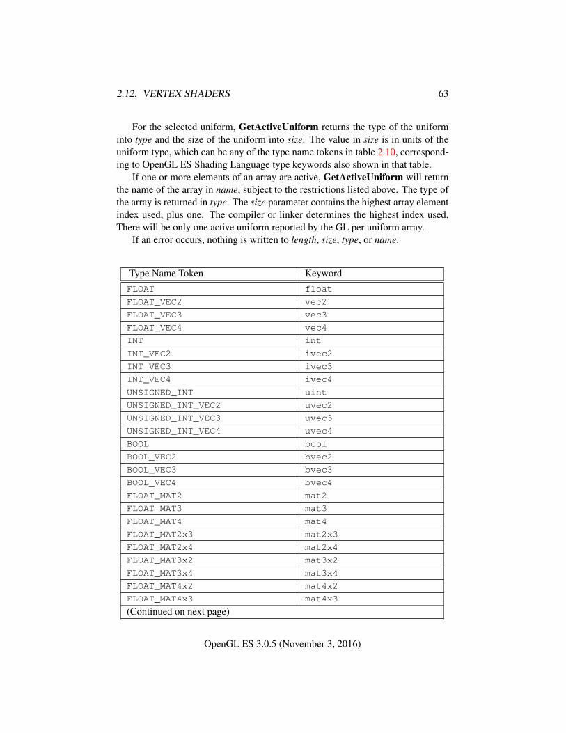
2.12. VERTEX SHADERS 63
For the selected uniform, GetActiveUniform returns the type of the uniforminto type and the size of the uniform into size. The value in size is in units of theuniform type, which can be any of the type name tokens in table 2.10, correspond-ing to OpenGL ES Shading Language type keywords also shown in that table.
If one or more elements of an array are active, GetActiveUniform will returnthe name of the array in name, subject to the restrictions listed above. The type ofthe array is returned in type. The size parameter contains the highest array elementindex used, plus one. The compiler or linker determines the highest index used.There will be only one active uniform reported by the GL per uniform array.
If an error occurs, nothing is written to length, size, type, or name.
Type Name Token KeywordFLOAT float
FLOAT_VEC2 vec2
FLOAT_VEC3 vec3
FLOAT_VEC4 vec4
INT int
INT_VEC2 ivec2
INT_VEC3 ivec3
INT_VEC4 ivec4
UNSIGNED_INT uint
UNSIGNED_INT_VEC2 uvec2
UNSIGNED_INT_VEC3 uvec3
UNSIGNED_INT_VEC4 uvec4
BOOL bool
BOOL_VEC2 bvec2
BOOL_VEC3 bvec3
BOOL_VEC4 bvec4
FLOAT_MAT2 mat2
FLOAT_MAT3 mat3
FLOAT_MAT4 mat4
FLOAT_MAT2x3 mat2x3
FLOAT_MAT2x4 mat2x4
FLOAT_MAT3x2 mat3x2
FLOAT_MAT3x4 mat3x4
FLOAT_MAT4x2 mat4x2
FLOAT_MAT4x3 mat4x3
(Continued on next page)
OpenGL ES 3.0.5 (November 3, 2016)
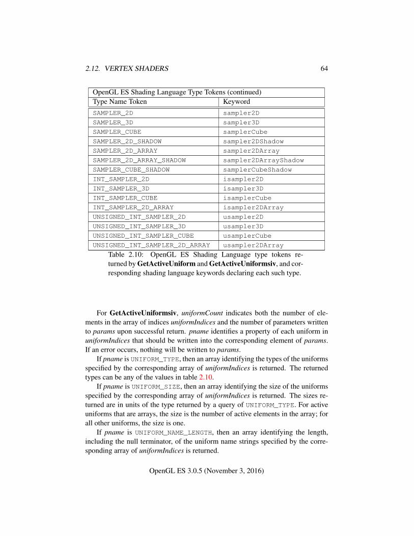
2.12. VERTEX SHADERS 64
OpenGL ES Shading Language Type Tokens (continued)Type Name Token KeywordSAMPLER_2D sampler2D
SAMPLER_3D sampler3D
SAMPLER_CUBE samplerCube
SAMPLER_2D_SHADOW sampler2DShadow
SAMPLER_2D_ARRAY sampler2DArray
SAMPLER_2D_ARRAY_SHADOW sampler2DArrayShadow
SAMPLER_CUBE_SHADOW samplerCubeShadow
INT_SAMPLER_2D isampler2D
INT_SAMPLER_3D isampler3D
INT_SAMPLER_CUBE isamplerCube
INT_SAMPLER_2D_ARRAY isampler2DArray
UNSIGNED_INT_SAMPLER_2D usampler2D
UNSIGNED_INT_SAMPLER_3D usampler3D
UNSIGNED_INT_SAMPLER_CUBE usamplerCube
UNSIGNED_INT_SAMPLER_2D_ARRAY usampler2DArray
Table 2.10: OpenGL ES Shading Language type tokens re-turned by GetActiveUniform and GetActiveUniformsiv, and cor-responding shading language keywords declaring each such type.
For GetActiveUniformsiv, uniformCount indicates both the number of ele-ments in the array of indices uniformIndices and the number of parameters writtento params upon successful return. pname identifies a property of each uniform inuniformIndices that should be written into the corresponding element of params.If an error occurs, nothing will be written to params.
If pname is UNIFORM_TYPE, then an array identifying the types of the uniformsspecified by the corresponding array of uniformIndices is returned. The returnedtypes can be any of the values in table 2.10.
If pname is UNIFORM_SIZE, then an array identifying the size of the uniformsspecified by the corresponding array of uniformIndices is returned. The sizes re-turned are in units of the type returned by a query of UNIFORM_TYPE. For activeuniforms that are arrays, the size is the number of active elements in the array; forall other uniforms, the size is one.
If pname is UNIFORM_NAME_LENGTH, then an array identifying the length,including the null terminator, of the uniform name strings specified by the corre-sponding array of uniformIndices is returned.
OpenGL ES 3.0.5 (November 3, 2016)
2.12. VERTEX SHADERS 65
If pname is UNIFORM_BLOCK_INDEX, then an array identifying the uniformblock index of each of the uniforms specified by the corresponding array of unifor-mIndices is returned. The index of a uniform associated with the default uniformblock is -1. The index of a uniform that is a member of an interface block declaredas an array of block instances is the index of the first block of the array.
If pname is UNIFORM_OFFSET, then an array of uniform buffer offsets is re-turned. For uniforms in a named uniform block, the returned value will be its offset,in basic machine units, relative to the beginning of the uniform block in the bufferobject data store. For uniforms in the default uniform block, -1 will be returned.For a uniform that is a member of an interface block declared as an array of blockinstances, the uniform will have the same offset in all block instances.
If pname is UNIFORM_ARRAY_STRIDE, then an array identifying the stridebetween elements, in basic machine units, of each of the uniforms specified bythe corresponding array of uniformIndices is returned. The stride of a uniformassociated with the default uniform block is -1. Note that this information onlymakes sense for uniforms that are arrays. For uniforms that are not arrays, but aredeclared in a named uniform block, an array stride of zero is returned.
If pname is UNIFORM_MATRIX_STRIDE, then an array identifying the stridebetween columns of a column-major matrix or rows of a row-major matrix, in ba-sic machine units, of each of the uniforms specified by the corresponding array ofuniformIndices is returned. The matrix stride of a uniform associated with the de-fault uniform block is -1. Note that this information only makes sense for uniformsthat are matrices. For uniforms that are not matrices, but are declared in a nameduniform block, a matrix stride of zero is returned.
If pname is UNIFORM_IS_ROW_MAJOR, then an array identifying whether eachof the uniforms specified by the corresponding array of uniformIndices is a row-major matrix or not is returned. A value of one indicates a row-major matrix, anda value of zero indicates a column-major matrix, a matrix in the default uniformblock, or a non-matrix.
2.12.6.1 Loading Uniform Variables In The Default Uniform Block
To load values into the uniform variables of the default uniform block of the pro-gram object that is currently in use, use the commands
void Uniform{1234}{if}( int location, T value );void Uniform{1234}{if}v( int location, sizei count, const
T value );void Uniform{1234}ui( int location, T value );
OpenGL ES 3.0.5 (November 3, 2016)
2.12. VERTEX SHADERS 66
void Uniform{1234}uiv( int location, sizei count, constT value );
void UniformMatrix{234}fv( int location, sizei count,boolean transpose, const float *value );
void UniformMatrix{2x3,3x2,2x4,4x2,3x4,4x3}fv(int location, sizei count, boolean transpose, constfloat *value );
The given values are loaded into the default uniform block uniform variable loca-tion identified by location.
The Uniform*f{v} commands will load count sets of one to four floating-pointvalues into a uniform location defined as a float, a floating-point vector, an array offloats, or an array of floating-point vectors.
The Uniform*i{v} commands will load count sets of one to four integer val-ues into a uniform location defined as a sampler, an integer, an integer vector, anarray of samplers, an array of integers, or an array of integer vectors. Only theUniform1i{v} commands can be used to load sampler values (see below).
The Uniform*ui{v} commands will load count sets of one to four unsignedinteger values into a uniform location defined as a unsigned integer, an unsignedinteger vector, an array of unsigned integers or an array of unsigned integer vectors.
The UniformMatrix{234}fv commands will load count 2× 2, 3× 3, or 4× 4matrices (corresponding to 2, 3, or 4 in the command name) of floating-point valuesinto a uniform location defined as a matrix or an array of matrices. If transposeis FALSE, the matrix is specified in column major order, otherwise in row majororder.
The UniformMatrix{2x3,3x2,2x4,4x2,3x4,4x3}fv commands will load count2×3, 3×2, 2×4, 4×2, 3×4, or 4×3 matrices (corresponding to the numbers in thecommand name) of floating-point values into a uniform location defined as a matrixor an array of matrices. The first number in the command name is the number ofcolumns; the second is the number of rows. For example, UniformMatrix2x4fvis used to load a matrix consisting of two columns and four rows. If transposeis FALSE, the matrix is specified in column major order, otherwise in row majororder.
When loading values for a uniform declared as a boolean, a boolean vector,an array of booleans, or an array of boolean vectors, the Uniform*i{v}, Uni-form*ui{v}, and Uniform*f{v} set of commands can be used to load booleanvalues. Type conversion is done by the GL. The uniform is set to FALSE if theinput value is 0 or 0.0f, and set to TRUE otherwise. The Uniform* command usedmust match the size of the uniform, as declared in the shader. For example, toload a uniform declared as a bvec2, any of the Uniform2{if ui}* commands may
OpenGL ES 3.0.5 (November 3, 2016)
2.12. VERTEX SHADERS 67
be used. An INVALID_OPERATION error will be generated if an attempt is madeto use a non-matching Uniform* command. In this example using Uniform1ivwould generate an error.
For all other uniform types the Uniform* command used must match thesize and type of the uniform, as declared in the shader. No type conversions aredone. For example, to load a uniform declared as a vec4, Uniform4f{v} must beused. To load a 3 × 3 matrix, UniformMatrix3fv must be used. An INVALID_-
OPERATION error will be generated if an attempt is made to use a non-matchingUniform* command. In this example, using Uniform4i{v} would generate anerror.
When loading N elements starting at an arbitrary position k in a uniform de-clared as an array, elements k through k + N − 1 in the array will be replacedwith the new values. Values for any array element that exceeds the highest arrayelement index used, as reported by GetActiveUniform, will be ignored by the GL.
If the value of location is -1, the Uniform* commands will silently ignore thedata passed in, and the current uniform values will not be changed.
If any of the following conditions occur, an INVALID_OPERATION error isgenerated by the Uniform* commands, and no uniform values are changed:
• if the size indicated in the name of the Uniform* command used does notmatch the size of the uniform declared in the shader,
• if the uniform declared in the shader is not of type boolean and the typeindicated in the name of the Uniform* command used does not match thetype of the uniform,
• if count is greater than one, and the uniform declared in the shader is not anarray variable,
• if no variable with a location of location exists in the program object cur-rently in use and location is not -1, or
• if there is no program object currently in use.
2.12.6.2 Uniform Blocks
The values of uniforms arranged in named uniform blocks are extracted from bufferobject storage. The mechanisms for placing individual uniforms in a buffer objectand connecting a uniform block to an individual buffer object are described below.
There is a set of implementation-dependent maximums for the number of ac-tive uniform blocks used by each shader (vertex and fragment). If the number ofuniform blocks used by any shader in the program exceeds its corresponding limit,
OpenGL ES 3.0.5 (November 3, 2016)
2.12. VERTEX SHADERS 68
the program will fail to link. The limits for vertex and fragment shaders can beobtained by calling GetIntegerv with pname values of MAX_VERTEX_UNIFORM_-BLOCKS and MAX_FRAGMENT_UNIFORM_BLOCKS, respectively.
Additionally, there is an implementation-dependent limit on the sum of thenumber of active uniform blocks used by each shader of a program. If a uniformblock is used by multiple shaders, each such use counts separately against thiscombined limit. The combined uniform block use limit can be obtained by callingGetIntegerv with a pname of MAX_COMBINED_UNIFORM_BLOCKS.
When a named uniform block is declared by multiple shaders in a program, itmust be declared identically in each shader. The uniforms within the block mustbe declared with the same names and types, and in the same order. If a programcontains multiple shaders with different declarations for the same named uniformblock, the program will fail to link.
2.12.6.3 Uniform Buffer Object Storage
When stored in buffer objects associated with uniform blocks, uniforms are repre-sented in memory as follows:
• Members of type bool are extracted from a buffer object by reading a singleuint-typed value at the specified offset. All non-zero values correspond totrue, and zero corresponds to false.
• Members of type int are extracted from a buffer object by reading a singleint-typed value at the specified offset.
• Members of type uint are extracted from a buffer object by reading a singleuint-typed value at the specified offset.
• Members of type float are extracted from a buffer object by reading asingle float-typed value at the specified offset.
• Vectors with N elements with basic data types of bool, int, uint, orfloat are extracted as N values in consecutive memory locations begin-ning at the specified offset, with components stored in order with the first(X) component at the lowest offset. The GL data type used for componentextraction is derived according to the rules for scalar members above.
• Column-major matrices with C columns and R rows (using the typematCxR, or simply matC if C = R) are treated as an array of C floating-point column vectors, each consisting of R components. The column vec-tors will be stored in order, with column zero at the lowest offset. The dif-
OpenGL ES 3.0.5 (November 3, 2016)
2.12. VERTEX SHADERS 69
ference in offsets between consecutive columns of the matrix will be re-ferred to as the column stride, and is constant across the matrix. The columnstride, UNIFORM_MATRIX_STRIDE, is an implementation-dependent valueand may be queried after a program is linked.
• Row-major matrices with C columns and R rows (using the type matCxR,or simply matC if C = R) are treated as an array of R floating-point rowvectors, each consisting of C components. The row vectors will be stored inorder, with row zero at the lowest offset. The difference in offsets betweenconsecutive rows of the matrix will be referred to as the row stride, and isconstant across the matrix. The row stride, UNIFORM_MATRIX_STRIDE, isan implementation-dependent value and may be queried after a program islinked.
• Arrays of scalars, vectors, and matrices are stored in memory by elementorder, with array member zero at the lowest offset. The difference in offsetsbetween each pair of elements in the array in basic machine units is referredto as the array stride, and is constant across the entire array. The array stride,UNIFORM_ARRAY_STRIDE, is an implementation-dependent value and maybe queried after a program is linked.
2.12.6.4 Standard Uniform Block Layout
By default, uniforms contained within a uniform block are extracted from bufferstorage in an implementation-dependent manner. Applications may query the off-sets assigned to uniforms inside uniform blocks with query functions provided bythe GL.
The layout qualifier provides shaders with control of the layout of uniformswithin a uniform block. When the std140 layout is specified, the offset of eachuniform in a uniform block can be derived from the definition of the uniform blockby applying the set of rules described below.
If a uniform block is declared in multiple shaders linked together into a singleprogram, the link will fail unless the uniform block declaration, including layoutqualifier, are identical in all such shaders.
When using the std140 storage layout, structures will be laid out in bufferstorage with its members stored in monotonically increasing order based on theirlocation in the declaration. A structure and each structure member have a baseoffset and a base alignment, from which an aligned offset is computed by roundingthe base offset up to a multiple of the base alignment. The base offset of the firstmember of a structure is taken from the aligned offset of the structure itself. Thebase offset of all other structure members is derived by taking the offset of the
OpenGL ES 3.0.5 (November 3, 2016)
2.12. VERTEX SHADERS 70
last basic machine unit consumed by the previous member and adding one. Eachstructure member is stored in memory at its aligned offset. The members of a top-level uniform block are laid out in buffer storage by treating the uniform block asa structure with a base offset of zero.
1. If the member is a scalar consuming N basic machine units, the base align-ment is N .
2. If the member is a two- or four-component vector with components consum-ing N basic machine units, the base alignment is 2N or 4N , respectively.
3. If the member is a three-component vector with components consuming Nbasic machine units, the base alignment is 4N .
4. If the member is an array of scalars or vectors, the base alignment and arraystride are set to match the base alignment of a single array element, accordingto rules (1), (2), and (3), and rounded up to the base alignment of a vec4. Thearray may have padding at the end; the base offset of the member followingthe array is rounded up to the next multiple of the base alignment.
5. If the member is a column-major matrix with C columns and R rows, thematrix is stored identically to an array of C column vectors with R compo-nents each, according to rule (4).
6. If the member is an array of S column-major matrices with C columns andR rows, the matrix is stored identically to a row of S × C column vectorswith R components each, according to rule (4).
7. If the member is a row-major matrix with C columns andR rows, the matrixis stored identically to an array of R row vectors with C components each,according to rule (4).
8. If the member is an array of S row-major matrices with C columns and Rrows, the matrix is stored identically to a row of S × R row vectors with Ccomponents each, according to rule (4).
9. If the member is a structure, the base alignment of the structure is N , whereN is the largest base alignment value of any of its members, and roundedup to the base alignment of a vec4. The individual members of this sub-structure are then assigned offsets by applying this set of rules recursively,where the base offset of the first member of the sub-structure is equal to thealigned offset of the structure. The structure may have padding at the end;the base offset of the member following the sub-structure is rounded up tothe next multiple of the base alignment of the structure.
OpenGL ES 3.0.5 (November 3, 2016)
2.12. VERTEX SHADERS 71
10. If the member is an array of S structures, the S elements of the array are laidout in order, according to rule (9).
2.12.6.5 Uniform Buffer Object Bindings
The value an active uniform inside a named uniform block is extracted from thedata store of a buffer object bound to one of an array of uniform buffer bindingpoints. The number of binding points can be queried using GetIntegerv with theconstant MAX_UNIFORM_BUFFER_BINDINGS.
Regions of buffer objects are bound as storage for uniform blocks by callingone of the commands BindBufferRange or BindBufferBase (see section 2.10.1.1)with target set to UNIFORM_BUFFER. In addition to the general errors described insection 2.10.1.1, BindBufferRange will generate an INVALID_VALUE error if in-dex is greater than or equal to the value of MAX_UNIFORM_BUFFER_BINDINGS, orif offset is not a multiple of the implementation-dependent alignment requirement(the value of UNIFORM_BUFFER_OFFSET_ALIGNMENT).
Each of a program’s active uniform blocks has a corresponding uniform bufferobject binding point. This binding point can be assigned by calling:
void UniformBlockBinding( uint program,uint uniformBlockIndex, uint uniformBlockBinding );
program is a name of a program object for which the command LinkProgramhas been issued in the past.
An INVALID_VALUE error is generated if uniformBlockIndex is not an activeuniform block index of program, or if uniformBlockBinding is greater than or equalto the value of MAX_UNIFORM_BUFFER_BINDINGS.
If successful, UniformBlockBinding specifies that program will use the datastore of the buffer object bound to the binding point uniformBlockBinding to extractthe values of the uniforms in the uniform block identified by uniformBlockIndex.
When executing shaders that access uniform blocks, the binding point corre-sponding to each active uniform block must be populated with a buffer object witha size no smaller than the minimum required size of the uniform block (the valueof UNIFORM_BLOCK_DATA_SIZE). For binding points populated by BindBuffer-Range, the size in question is the value of the size parameter. If any active uniformblock is not backed by a sufficiently large buffer object, the results of shader ex-ecution are undefined, and may result in GL interruption or termination. Shadersmay be executed to process the primitives and vertices specified by vertex arraycommands (see section 2.9).
When a program object is linked or re-linked, the uniform buffer object bindingpoint assigned to each of its active uniform blocks is reset to zero.
OpenGL ES 3.0.5 (November 3, 2016)
2.12. VERTEX SHADERS 72
2.12.7 Samplers
Samplers are special uniforms used in the OpenGL ES Shading Language to iden-tify the texture object used for each texture lookup. The value of a sampler in-dicates the texture image unit being accessed. Setting a sampler’s value to iselects texture image unit number i. The values of i range from zero to theimplementation-dependent maximum supported number of texture image units mi-nus one.
The type of the sampler identifies the target on the texture image unit. Thetexture object bound to that texture image unit’s target is then used for the texturelookup. For example, a variable of type sampler2D selects target TEXTURE_2Don its texture image unit. Binding of texture objects to targets is done as usual withBindTexture. Selecting the texture image unit to bind to is done as usual withActiveTexture.
The location of a sampler needs to be queried with GetUniformLocation, justlike any uniform variable. Sampler values need to be set by calling Uniform1i{v}.Loading samplers with any of the other Uniform* entry points is not allowed andwill result in an INVALID_OPERATION error. Loading samplers with values out-side of the range from zero to the implementation-dependent maximum supportednumber of texture image units minus one will result in an INVALID_VALUE error.
It is not allowed to have variables of different sampler types pointing to thesame texture image unit within a program object. This situation can only be de-tected at the next rendering command issued which triggers shader invocations,and an INVALID_OPERATION error will then be generated.
Active samplers are samplers actually being used in a program object. TheLinkProgram command determines if a sampler is active or not. The LinkPro-gram command will attempt to determine if the active samplers in the shader(s)contained in the program object exceed the maximum allowable limits. If it deter-mines that the count of active samplers exceeds the allowable limits, then the linkfails (these limits can be different for different types of shaders). Each active sam-pler variable counts against the limit, even if multiple samplers refer to the sametexture image unit.
2.12.8 Output Variables
A vertex shader may define one or more output variables or outputs (see theOpenGL ES Shading Language Specification).
The OpenGL ES Shading Language Specification also defines a set of built-inoutputs that vertex shaders can write to (see section 7.1 of the OpenGL ES ShadingLanguage Specification). These output variables are used to communicate values to
OpenGL ES 3.0.5 (November 3, 2016)
2.12. VERTEX SHADERS 73
the fixed-function processing that occurs after vertex shading and to the fragmentshader.
The values of all output variables are expected to be interpolated across theprimitive being rendered, unless flatshaded.
The number of components (individual scalar numeric values) of output vari-ables that can be written by the vertex shader is given by the value of theimplementation-dependent constant MAX_VERTEX_OUTPUT_COMPONENTS. Out-puts declared as vectors, matrices, and arrays will all consume multiple compo-nents.
When a program is linked, all components of any outputs written by a vertexshader will count against this limit. A program whose vertex shader writes morethan the value of MAX_VERTEX_OUTPUT_COMPONENTS components worth of out-puts may fail to link, unless device-dependent optimizations are able to make theprogram fit within available hardware resources.
Additionally, there is a limit on the total number of components used asvertex shader outputs or fragment shader inputs. This limit is given by thevalue of the implementation-dependent constant MAX_VARYING_COMPONENTS.The implementation-dependent constant MAX_VARYING_VECTORS has a valueequal to the value of MAX_VARYING_COMPONENTS divided by four. Each out-put variable component used as either a vertex shader output or fragment shaderinput count against this limit, except for the components of gl_Position. A pro-gram that accesses more than this limit’s worth of components of outputs may failto link, unless device-dependent optimizations are able to make the program fitwithin available hardware resources.
Each program object can specify a set of one or more vertex shader outputvariables to be recorded in transform feedback mode (see section 2.15). Transformfeedback records the values of the selected vertex shader output variables from theemitted vertices. The values to record are specified with the command
void TransformFeedbackVaryings( uint program,sizei count, const char * const *varyings,enum bufferMode );
program specifies the program object. count specifies the number of out-put variables used for transform feedback. varyings is an array of count zero-terminated strings specifying the names of the outputs to use for transform feed-back. The variables specified in varyings can be either built-in (beginning with"gl_") or user-defined variables. Output variables are written out in the or-der they appear in the array varyings. bufferMode is either INTERLEAVED_-
ATTRIBS or SEPARATE_ATTRIBS, and identifies the mode used to capture the
OpenGL ES 3.0.5 (November 3, 2016)
2.12. VERTEX SHADERS 74
outputs when transform feedback is active. The error INVALID_VALUE is gener-ated if bufferMode is SEPARATE_ATTRIBS and count is greater than the value ofthe implementation-dependent limit MAX_TRANSFORM_FEEDBACK_SEPARATE_-ATTRIBS.
The state set by TransformFeedbackVaryings has no effect on the execu-tion of the program until program is subsequently linked. When LinkProgramis called, the program is linked so that the values of the specified outputs for thevertices of each primitive generated by the GL are written to a single buffer object(if the buffer mode is INTERLEAVED_ATTRIBS) or multiple buffer objects (if thebuffer mode is SEPARATE_ATTRIBS). A program will fail to link if:
• any variable name specified in the varyings array is not declared as an outputin the vertex shader;
• any two entries in the varyings array specify the same output variable;
• the total number of components to capture in any output in varyings is greaterthan the constant MAX_TRANSFORM_FEEDBACK_SEPARATE_COMPONENTSand the buffer mode is SEPARATE_ATTRIBS; or
• the total number of components to capture is greater than the constantMAX_TRANSFORM_FEEDBACK_INTERLEAVED_COMPONENTS and the buffermode is INTERLEAVED_ATTRIBS.
When a program is linked, a list of output variables that will be captured intransform feedback mode is built as described in section 2.12.3. The variables inthis list are assigned consecutive indices, beginning with zero. The total number ofvariables in the list may be queried by calling GetProgramiv (section 6.1.12) witha pname of TRANSFORM_FEEDBACK_VARYINGS. The command
void GetTransformFeedbackVarying( uint program,uint index, sizei bufSize, sizei *length, sizei *size,enum *type, char *name );
can be used to determine properties of the variable with an index of index in the listof output variables that will be captured in transform feedback mode for programobject program. If index is greater then or equal to the value of TRANSFORM_-FEEDBACK_VARYINGS, the error INVALID_VALUE is generated.
The name of the selected output is returned as a null-terminated string in name.The actual number of characters written into name, excluding the null terminator,is returned in length. If length is NULL, no length is returned. The maximumnumber of characters that may be written into name, including the null terminator,
OpenGL ES 3.0.5 (November 3, 2016)
2.12. VERTEX SHADERS 75
is specified by bufSize. The returned output name can be the name of either abuilt-in (beginning with "gl_") or user-defined output variable. See the OpenGLES Shading Language Specification for a complete list. The length of the longestoutput name in program is given by TRANSFORM_FEEDBACK_VARYING_MAX_-
LENGTH, which can be queried with GetProgramiv (see section 6.1.12).The type of the selected output is returned into type. The size of the output is
returned into size. The value in size is in units of the type returned in type. Thetype returned can be any of the scalar, vector, or matrix attribute types returned byGetActiveAttrib. If an error occurred, the return parameters length, size, type andname will be unmodified.
2.12.9 Shader Execution
If a successfully linked program object that contains a vertex shader is made currentby calling UseProgram, the executable version of the vertex shader is used toprocess incoming vertex values.
The following operations are applied to vertices processed by the vertex shader:
• Perspective division on clip coordinates (section 2.13).
• Viewport mapping, including depth range scaling (section 2.13.1).
• Flatshading (section 2.17).
• Clipping (section 2.18).
• Front face determination (section 3.6.1).
• Generic attribute clipping (section 2.18.1).
There are several special considerations for vertex shader execution describedin the following sections.
2.12.9.1 Shader Texturing
This section describes texture functionality that is accessible through vertex or frag-ment shaders. Also refer to section 3.8 and to section 8.7 of the OpenGL ES Shad-ing Language Specification.
OpenGL ES 3.0.5 (November 3, 2016)
2.12. VERTEX SHADERS 76
2.12.9.2 Texel Fetches
The OpenGL ES Shading Language texel fetch functions provide the ability to ex-tract a single texel from a specified texture image. The integer coordinates passedto the texel fetch functions are used as the texel coordinates (i, j, k) into the tex-ture image. This in turn means the texture image is point-sampled (no filtering isperformed), but the remaining steps of texture access (described below) are stillapplied.
The level of detail accessed is computed by adding the specified level-of-detailparameter lod to the base level of the texture, levelbase.
The texel fetch functions can not perform depth comparisons or access cubemaps. Unlike filtered texel accesses, texel fetches do not support LOD clampingor any texture wrap mode, and do not replace the specified level of detail with thebase level when the minification filter is NEAREST or LINEAR.
The results of the texel fetch are undefined if any of the following conditionshold:
• the computed level of detail is less than the texture’s base level (levelbase) orgreater than the maximum defined level, q (see section 3.8.10.4).
• the computed level of detail is not the texture’s base level and the texture’sminification filter is NEAREST or LINEAR
• the layer specified for array textures is negative or greater than the numberof layers in the array texture,
• the texel coordinates (i, j, k) refer to a texel outside the defined extents ofthe computed level of detail, where any of
i < 0 i ≥ wt
j < 0 j ≥ htk < 0 k ≥ dt
and the size parameters wt, ht, and dt refer to the width, height, and depthof the image, as defined in section 3.8.3.
• the texture being accessed is not complete, as defined in section 3.8.13.
2.12.9.3 Texture Size Query
The OpenGL ES Shading Language texture size functions provide the ability toquery the size of a texture image. The LOD value lod passed in as an argument
OpenGL ES 3.0.5 (November 3, 2016)
2.12. VERTEX SHADERS 77
to the texture size functions is added to the levelbase of the texture to determinea texture image level. The dimensions of that image level are then returned. Ifthe computed texture image level is outside the range [levelbase, q], the results areundefined. When querying the size of an array texture, both the dimensions andthe layer index are returned.
2.12.9.4 Texture Access
Shaders have the ability to do a lookup into a texture map. The maximum num-ber of texture image units available to vertex or fragment shaders are respectivelythe values of the implementation-dependent constants MAX_VERTEX_TEXTURE_-IMAGE_UNITS and MAX_TEXTURE_IMAGE_UNITS. The vertex shader and frag-ment shader combined cannot use more than the value of MAX_COMBINED_-
TEXTURE_IMAGE_UNITS texture image units. If both the vertex shader and frag-ment shader access the same texture image unit, each such access counts separatelyagainst the MAX_COMBINED_TEXTURE_IMAGE_UNITS limit.
When a texture lookup is performed in a vertex shader, the filtered texture valueτ is computed in the manner described in sections 3.8.10 and 3.8.11, and convertedto a texture base color Cb as shown in table 3.24, followed by application of thetexture swizzle as described in section 3.9.2.1 to compute the texture source colorCs and As.
The resulting four-component vector (Rs, Gs, Bs, As) is returned to the shader.Texture lookup functions (see section 8.7 of the OpenGL ES Shading LanguageSpecification) may return floating-point, signed, or unsigned integer values de-pending on the function and the internal format of the texture.
In a vertex shader, it is not possible to perform automatic level-of-detail calcu-lations using partial derivatives of the texture coordinates with respect to windowcoordinates as described in section 3.8.10. Hence, there is no automatic selectionof an image array level. Minification or magnification of a texture map is controlledby a level-of-detail value optionally passed as an argument in the texture lookupfunctions. If the texture lookup function supplies an explicit level-of-detail value l,then the pre-bias level-of-detail value λbase(x, y) = l (replacing equation 3.16). Ifthe texture lookup function does not supply an explicit level-of-detail value, thenλbase(x, y) = 0. The scale factor ρ(x, y) and its approximation function f(x, y)(see equation 3.20) are ignored.
Texture lookups involving textures with depth component data generate a tex-ture base color Cb either using depth data directly or by performing a comparisonwith the Dref value used to perform the lookup, as described in section 3.8.15.1.The resulting value Rt is then expanded to a color Cb = (Rt, 0, 0, 1), and swiz-zling is performed as described in section 3.9.2.1, but only the first component
OpenGL ES 3.0.5 (November 3, 2016)
2.12. VERTEX SHADERS 78
Cs[0] is returned to the shader when a comparison has been performed. The com-parison operation is requested in the shader by using any of the shadow samplertypes (sampler*Shadow), and in the texture using the TEXTURE_COMPARE_MODEparameter. These requests must be consistent; the results of a texture lookup areundefined if any of the following conditions are true:
• The sampler used in a texture lookup function is not one of the shadow sam-pler types, the texture object’s base internal format is DEPTH_COMPONENTor DEPTH_STENCIL, and the TEXTURE_COMPARE_MODE is not NONE.
• The sampler used in a texture lookup function is one of the shadow sam-pler types, the texture object’s base internal format is DEPTH_COMPONENTor DEPTH_STENCIL, and the TEXTURE_COMPARE_MODE is NONE.
• The sampler used in a texture lookup function is one of the shadow sam-pler types, and the texture object’s base internal format is not DEPTH_-COMPONENT or DEPTH_STENCIL.
The stencil index texture internal component is ignored if the base internalformat is DEPTH_STENCIL.
If a sampler is used in a vertex shader and the sampler’s associated texture isnot complete, as defined in section 3.8.13, (0, 0, 0, 1) will be returned for a non-shadow sampler and 0 for a shadow sampler.
2.12.9.5 Shader Inputs
Besides having access to vertex attributes and uniform variables, vertex shaderscan access the read-only built-in variables gl_VertexID and gl_InstanceID.
gl_VertexID holds the integer index i implicitly passed by DrawArrays orone of the other drawing commands defined in section 2.9.3. The value of gl_-VertexID is defined if and only if all enabled vertex arrays have non-zero bufferobject bindings.
gl_InstanceID holds the integer instance number of the current primitive inan instanced draw call (see section 2.9.3).
Section 7.1 of the OpenGL ES Shading Language Specification also describesthese variables.
2.12.9.6 Shader Outputs
A vertex shader can write to user-defined output variables. These values will be in-terpolated across the primitive it outputs, unless they are specified to be flat shaded.
OpenGL ES 3.0.5 (November 3, 2016)
2.12. VERTEX SHADERS 79
Refer to sections 4.3.6, 7.1, and 7.6 of the OpenGL ES Shading Language Specifi-cation for more detail.
The built-in output gl_Position is intended to hold the homogeneous vertexposition. Writing gl_Position is optional.
The built in output gl_PointSize, if written, holds the size of the point to berasterized, measured in pixels.
2.12.9.7 Validation
It is not always possible to determine at link time if a program object actually willexecute. Therefore validation is done when the first rendering command whichtriggers shader invocations is issued, to determine if the currently active programobject can be executed. If there is no current program object, the results of render-ing commands are undefined. However, this is not an error. If there is a currentprogram object and it cannot be executed then no fragments will be rendered, andthe error INVALID_OPERATION will be generated.
This error is generated by any command that transfers vertices to the GL if:
• any two active samplers in the current program object are of different types,but refer to the same texture image unit,
• the sum of the number of active samplers in the program exceeds the maxi-mum number of texture image units allowed.
The INVALID_OPERATION error reported by these rendering commands maynot provide enough information to find out why the currently active program objectwould not execute. No information at all is available about a program object thatwould still execute, but is inefficient or suboptimal given the current GL state. Asa development aid, use the command
void ValidateProgram( uint program );
to validate the program object program against the current GL state. Each programobject has a boolean status, VALIDATE_STATUS, that is modified as a result ofvalidation. This status can be queried with GetProgramiv (see section 6.1.12).If validation succeeded this status will be set to TRUE, otherwise it will be set toFALSE. If validation succeeded the program object is guaranteed to execute, giventhe current GL state. If validation failed, the program object is guaranteed to notexecute, given the current GL state.
ValidateProgram will check for all of the error conditions described in thissection, and may check for other conditions as well. For example, it could give a
OpenGL ES 3.0.5 (November 3, 2016)
2.12. VERTEX SHADERS 80
hint on how to optimize some piece of shader code. The information log of pro-gram is overwritten with information on the results of the validation, which couldbe an empty string. The results written to the information log are typically onlyuseful during application development; an application should not expect differentGL implementations to produce identical information.
A shader should not fail to compile, and a program object should not fail tolink due to lack of instruction space or lack of temporary variables. Implementa-tions should ensure that all valid shaders and program objects may be successfullycompiled, linked and executed.
2.12.9.8 Undefined Behavior
When using array or matrix variables in a shader, it is possible to access a vari-able with an index computed at run time that is outside the declared extent of thevariable. Such out-of-bounds accesses have undefined behavior, and system er-rors (possibly including program termination) may occur. The level of protectionprovided against such errors in the shader is implementation-dependent.
2.12.10 Required State
The GL maintains state to indicate which shader and program object names are inuse. Initially, no shader or program objects exist, and no names are in use.
The state required per shader object consists of:
• An unsigned integer specifying the shader object name.
• An integer holding the value of SHADER_TYPE.
• A boolean holding the delete status, initially FALSE.
• A boolean holding the status of the last compile, initially FALSE.
• An array of type char containing the information log, initially empty.
• An integer holding the length of the information log.
• An array of type char containing the concatenated shader string, initiallyempty.
• An integer holding the length of the concatenated shader string.
The state required per program object consists of:
OpenGL ES 3.0.5 (November 3, 2016)
2.12. VERTEX SHADERS 81
• An unsigned integer indicating the program object name.
• A boolean holding the delete status, initially FALSE.
• A boolean holding the status of the last link attempt, initially FALSE.
• A boolean holding the status of the last validation attempt, initially FALSE.
• An integer holding the number of attached shader objects.
• A list of unsigned integers to keep track of the names of the shader objectsattached.
• An array of type char containing the information log, initially empty.
• An integer holding the length of the information log.
• An integer holding the number of active uniforms.
• For each active uniform, three integers, holding its location, size, and type,and an array of type char holding its name.
• An array holding the values of each active uniform.
• An integer holding the number of active attributes.
• For each active attribute, three integers holding its location, size, and type,and an array of type char holding its name.
• A boolean holding the hint to the retrievability of the program binary, ini-tially FALSE.
Additional state required to support transform feedback consists of:
• An integer holding the transform feedback mode, initially INTERLEAVED_-ATTRIBS.
• An integer holding the number of outputs to be captured, initially zero.
• An integer holding the length of the longest output name being captured,initially zero.
• For each output being captured, two integers holding its size and type, andan array of type char holding its name.
OpenGL ES 3.0.5 (November 3, 2016)
2.13. COORDINATE TRANSFORMATIONS 82
Additionally, one unsigned integer is required to hold the name of the current pro-gram object, if any.
This list of program object state is not complete. Tables 6.18-6.21 describeadditional program object state specific to program binaries and uniform blocks.Table 6.22 describes state related to vertex shaders that is not program object state.
2.13 Coordinate Transformations
Clip coordinates for a vertex result from vertex shader execution, which yields avertex coordinate gl_Position. Perspective division on clip coordinates yieldsnormalized device coordinates, followed by a viewport transformation to convertthese coordinates into window coordinates.
If a vertex in clip coordinates is given by
xcyczcwc
then the vertex’s normalized device coordinates arexdyd
zd
=
xcwcycwczcwc
.
2.13.1 Controlling the Viewport
The viewport transformation is determined by the viewport’s width and height inpixels, px and py, respectively, and its center (ox, oy) (also in pixels). The vertex’s
window coordinates,
xwywzw
, are given by
xwywzw
=
px2 xd + oxpy2 yd + oy
f−n2 zd + n+f
2
.
The factor and offset applied to zd encoded by n and f are set using
void DepthRangef( float n, float f );
zw may be represented using either a fixed-point or floating-point representation.However, a floating-point representation must be used if the draw framebuffer hasa floating-point depth buffer. If an m-bit fixed-point representation is used, we
OpenGL ES 3.0.5 (November 3, 2016)
2.14. ASYNCHRONOUS QUERIES 83
assume that it represents each value k/(2m− 1), where k ∈ {0, 1, . . . , 2m− 1}, ask (e.g. 1.0 is represented in binary as a string of all ones). The parameters n and fare clamped to the range [0, 1] when specified.
Viewport transformation parameters are specified using
void Viewport( int x, int y, sizei w, sizei h );
where x and y give the x and y window coordinates of the viewport’s lower leftcorner and w and h give the viewport’s width and height, respectively. The viewportparameters shown in the above equations are found from these values as
ox = x+ w2
oy = y + h2
px = wpy = h.
Viewport width and height are clamped to implementation-dependent maxi-mums when specified. The maximum width and height may be found by issuingan appropriate Get command (see chapter 6). The maximum viewport dimensionsmust be greater than or equal to the larger of the visible dimensions of the displaybeing rendered to (if a display exists), and the largest renderbuffer image whichcan be successfully created and attached to a framebuffer object (see chapter 4).INVALID_VALUE is generated if either w or h is negative.
The state required to implement the viewport transformation is four integersand two clamped floating-point values. In the initial state, w and h are set to thewidth and height, respectively, of the window into which the GL is to do its ren-dering. If the default framebuffer is bound but no default framebuffer is associatedwith the GL context (see chapter 4), then w and h are initially set to zero. ox, oy,n, and f are set to w
2 , h2 , 0.0, and 1.0, respectively.
2.14 Asynchronous Queries
Asynchronous queries provide a mechanism to return information about the pro-cessing of a sequence of GL commands. There are two query types sup-ported by the GL. Primitive queries with a target of TRANSFORM_FEEDBACK_-PRIMITIVES_WRITTEN (see section 2.16) return information on the number ofprimitives written to one or more buffer objects. Occlusion queries (see sec-tion 4.1.6) set a boolean to true when any fragments or samples pass the depthtest.
The results of asynchronous queries are not returned by the GL immediatelyafter the completion of the last command in the set; subsequent commands can
OpenGL ES 3.0.5 (November 3, 2016)
2.14. ASYNCHRONOUS QUERIES 84
be processed while the query results are not complete. When available, the queryresults are stored in an associated query object. The commands described in sec-tion 6.1.7 provide mechanisms to determine when query results are available andreturn the actual results of the query. The name space for query objects is theunsigned integers, with zero reserved by the GL.
Each type of query supported by the GL has an active query object name. Ifthe active query object name for a query type is non-zero, the GL is currentlytracking the information corresponding to that query type and the query resultswill be written into the corresponding query object. If the active query object for aquery type name is zero, no such information is being tracked.
The command
void GenQueries( sizei n, uint *ids );
returns n previously unused query object names in ids. These names are marked asused, for the purposes of GenQueries only, but no object is associated with themuntil the first time they are used by BeginQuery.
A query object is created and made active by calling
void BeginQuery( enum target, uint id );
passing it a name id returned by GenQueries. target indicates the type of query tobe performed; valid values of target are defined in subsequent sections.The result-ing query object is a new state vector, comprising all the state and with the sameinitial values listed in table 6.23.
BeginQuery can also be used to make active an existing query object of typetarget.
BeginQuery fails and an INVALID_OPERATION error is generated if id is nota name returned from a previous call to GenQueries, or if such a name has sincebeen deleted with DeleteQueries.
BeginQuery sets the active query object name for the query type given bytarget to id. BeginQuery generates an INVALID_OPERATION error if any of thefollowing conditions hold: id is zero; id is the name of an existing query objectwhose type does not match target; id is the active query object name for anyquery type; or the active query object name for target is non-zero (for the tar-gets ANY_SAMPLES_PASSED and ANY_SAMPLES_PASSED_CONSERVATIVE, theactive query for either target is non-zero).
The command
void EndQuery( enum target );
OpenGL ES 3.0.5 (November 3, 2016)
2.15. TRANSFORM FEEDBACK 85
marks the end of the sequence of commands to be tracked for the query type givenby target. The active query object for target is updated to indicate that query resultsare not available, and the active query object name for target is reset to zero. Whenthe commands issued prior to EndQuery have completed and a final query resultis available, the query object active when EndQuery is called is updated by theGL. The query object is updated to indicate that the query results are available andto contain the query result. If the active query object name for target is zero whenEndQuery is called, the error INVALID_OPERATION is generated.
Query objects are deleted by calling
void DeleteQueries( sizei n, const uint *ids );
ids contains n names of query objects to be deleted. After a query object is deleted,its name is again unused. If an active query object is deleted its name immediatelybecomes unused, but the underlying object is not deleted until it is no longer active(see section D.1). Unused names in ids that have been marked as used for thepurposes of GenQueries are marked as unused again. Unused names in ids aresilently ignored, as is the value zero.
Query objects contain two pieces of state: a single bit indicating whether aquery result is available, and an integer containing the query result value. Thenumber of bits, n, used to represent the query result is implementation-dependentand may vary by query object type. In the initial state of a query object, the resultis not available (the flag is FALSE) and the result value is zero.
If the query result overflows (exceeds the value 2n − 1), its value becomesundefined. It is recommended, but not required, that implementations handle thisoverflow case by saturating at 2n − 1 and incrementing no further.
The necessary state for each query type is an unsigned integer holding theactive query object name (zero if no query object is active), and any state necessaryto keep the current results of an asynchronous query in progress. Only a single typeof occlusion query can be active at one time, so the required state for occlusionqueries is shared.
2.15 Transform Feedback
Transform feedback mode captures the values of output variables written by thevertex shader. The vertices are captured before flatshading and clipping. Thetransformed vertices may be optionally discarded after being stored into one ormore buffer objects, or they can be passed on down to the clipping stage for furtherprocessing. The set of output variables captured is determined when a program islinked.
OpenGL ES 3.0.5 (November 3, 2016)
2.15. TRANSFORM FEEDBACK 86
2.15.1 Transform Feedback Objects
The set of buffer objects used to capture vertex output variables and related stateare stored in a transform feedback object. The set of output variables capturedin transform feedback mode is determined using the state of the active programobject. The name space for transform feedback objects is the unsigned integers.The name zero designates the default transform feedback object.
The command
void GenTransformFeedbacks( sizei n, uint *ids );
returns n previously unused transform feedback object names in ids. These namesare marked as used, for the purposes of GenTransformFeedbacks only, but theydo not acquire transform feedback state until they are first bound.
Transform feedback objects are deleted by calling
void DeleteTransformFeedbacks( sizei n, constuint *ids );
ids contains n names of transform feedback objects to be deleted. After a trans-form feedback object is deleted it has no contents, and its name is again unused.Unused names in ids that have been marked as used for the purposes of GenTrans-formFeedbacks are marked as unused again. Unused names in ids are silentlyignored, as is the value zero. The default transform feedback object cannot bedeleted.
The error INVALID_OPERATION is generated by DeleteTransformFeedbacksif the transform feedback operation for any object named by ids is currently active.
A transform feedback object is created by binding a name returned by Gen-TransformFeedbacks with the command
void BindTransformFeedback( enum target, uint id );
target must be TRANSFORM_FEEDBACK and id is the transform feedback objectname. The resulting transform feedback object is a new state vector, comprisingall the state and with the same initial values listed in table 6.24. Additionally, thenew object is bound to the GL state vector and is used for subsequent transformfeedback operations.
BindTransformFeedback can also be used to bind an existing transform feed-back object to the GL state for subsequent use. If the bind is successful, no changeis made to the state of the newly bound transform feedback object and any previousbinding to target is broken.
OpenGL ES 3.0.5 (November 3, 2016)
2.15. TRANSFORM FEEDBACK 87
While a transform feedback object is bound, GL operations on the target towhich it is bound affect the bound transform feedback object, and queries of thetarget to which a transform feedback object is bound return state from the boundobject. When buffer objects are bound for transform feedback, they are attached tothe currently bound transform feedback object. Buffer objects are used for trans-form feedback only if they are attached to the currently bound transform feedbackobject.
In the initial state, a default transform feedback object is bound and treated asa transform feedback object with a name of zero. That object is bound any timeBindTransformFeedback is called with id of zero.
The error INVALID_OPERATION is generated by BindTransformFeedback ifthe transform feedback operation is active on the currently bound transform feed-back object, and that operation is not paused (as described below).
BindTransformFeedback fails and an INVALID_OPERATION error is gener-ated if id is not zero or a name returned from a previous call to GenTransform-Feedbacks, or if such a name has since been deleted with DeleteTransformFeed-backs.
2.15.2 Transform Feedback Primitive Capture
Transform feedback for the currently bound transform feedback object is startedand finished by calling
void BeginTransformFeedback( enum primitiveMode );
and
void EndTransformFeedback( void );
respectively. Transform feedback is said to be active after a call to BeginTrans-formFeedback and inactive after a call to EndTransformFeedback. EndTrans-formFeedback first performs an implicit ResumeTransformFeedback (see be-low) if transform feedback is paused. primitiveMode is one of TRIANGLES, LINES,or POINTS, and specifies the output type of primitives that will be recorded into thebuffer objects bound for transform feedback (see below). primitiveMode restrictsthe primitive types that may be rendered while transform feedback is active and notpaused.
Transform feedback commands must be paired; the error INVALID_-
OPERATION is generated by BeginTransformFeedback if transform feedback isactive for the current transform feedback object, and by EndTransformFeedbackif transform feedback is inactive. Transform feedback is initially inactive.
OpenGL ES 3.0.5 (November 3, 2016)
2.15. TRANSFORM FEEDBACK 88
Transform feedback operations for the currently bound transform feedback ob-ject may be paused and resumed by calling
void PauseTransformFeedback( void );
and
void ResumeTransformFeedback( void );
respectively. When transform feedback operations are paused, transform feedbackis still considered active and changing most transform feedback state related to theobject results in an error. However, a new transform feedback object may be boundwhile transform feedback is paused. The error INVALID_OPERATION is gener-ated by PauseTransformFeedback if the currently bound transform feedback isnot active or is paused. The error INVALID_OPERATION is generated by Resume-TransformFeedback if the currently bound transform feedback is not active or isnot paused.
When transform feedback is active and not paused, all geometric primitivesgenerated must match the value of primitiveMode passed to BeginTransform-Feedback. The error INVALID_OPERATION is generated by DrawArrays andDrawArraysInstanced if mode is not identical to primitiveMode. The errorINVALID_OPERATION is also generated by DrawElements, DrawElementsIn-stanced, and DrawRangeElements while transform feedback is active and notpaused, regardless of mode Any primitive type may be used while transform feed-back is paused.
Regions of buffer objects are bound as the targets of transform feedback bycalling one of the commands BindBufferRange or BindBufferBase (see sec-tion 2.10.1.1) with target set to TRANSFORM_FEEDBACK_BUFFER. In addition tothe general errors described in section 2.10.1.1, BindBufferRange will generatean INVALID_VALUE error if index is greater than or equal to the value of MAX_-TRANSFORM_FEEDBACK_SEPARATE_ATTRIBS, or if either offset or size is not amultiple of 4.
When an individual point, line, or triangle primitive reaches the transform feed-back stage while transform feedback is active and not paused, the values of thespecified output variables of the vertex are appended to the buffer objects boundto the transform feedback binding points. The output variables of the first vertexreceived after BeginTransformFeedback are written at the starting offsets of thebound buffer objects set by BindBufferRange, and subsequent output variablesare appended to the buffer object. When capturing line and triangle primitives, alloutput variables of the first vertex are written first, followed by output variables
OpenGL ES 3.0.5 (November 3, 2016)
2.15. TRANSFORM FEEDBACK 89
of the subsequent vertices. When writing output variables that are arrays, individ-ual array elements are written in order. For multi-component output variables orelements of output arrays, the individual components are written in order. Vari-ables declared with lowp or mediump precision are promoted to highp beforebeing written. See Table 2.11 showing the output buffer type for each OpenGL ESShading Language variable type. The value for any output variable specified to bestreamed to a buffer object but not actually written by a vertex shader is undefined.
When transform feedback is paused, no vertices are recorded. When transformfeedback is resumed, subsequent vertices are appended to the bound buffer ob-jects immediately following the last vertex written before transform feedback waspaused.
Incomplete primitives are not recorded.Transform feedback can operate in either INTERLEAVED_ATTRIBS or
SEPARATE_ATTRIBS mode.In INTERLEAVED_ATTRIBS mode, the values of one or more output variables
written by a vertex shader are written, interleaved, into the buffer object bound tothe first transform feedback binding point (index = 0). If more than one outputvariable is written to a buffer object, they will be recorded in the order specified byTransformFeedbackVaryings (see section 2.12.8).
In SEPARATE_ATTRIBS mode, the first output variable specified by Trans-formFeedbackVaryings is written to the first transform feedback binding point;subsequent output variables are written to the subsequent transform feedback bind-ing points. The total number of variables that may be captured in separate mode isgiven by MAX_TRANSFORM_FEEDBACK_SEPARATE_ATTRIBS.
The error INVALID_OPERATION is generated by DrawArrays and DrawAr-raysInstanced if recording the vertices of a primitive to the buffer objects beingused for transform feedback purposes would result in either exceeding the limits ofany buffer object’s size, or in exceeding the end position offset + size − 1, as setby BindBufferRange.
In either separate or interleaved modes, all transform feedback binding pointsthat will be written to must have buffer objects bound when BeginTransformFeed-back is called. The error INVALID_OPERATION is generated by BeginTrans-formFeedback if any binding point used in transform feedback mode does nothave a buffer object bound. In interleaved mode, only the first buffer object bind-ing point is ever written to. The error INVALID_OPERATION is also generatedby BeginTransformFeedback if no binding points would be used, either becauseno program object is active or because the active program object has specified nooutput variables to record.
When BeginTransformFeedback is called, the set of output variables capturedduring transform feedback is taken from the active program object and may not be
OpenGL ES 3.0.5 (November 3, 2016)
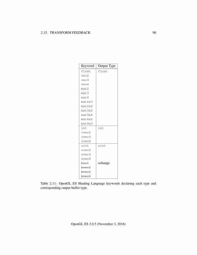
2.15. TRANSFORM FEEDBACK 90
Keyword Output Typefloat float
vec2
vec3
vec4
mat2
mat3
mat4
mat2x3
mat2x4
mat3x2
mat3x4
mat4x2
mat4x3
int int
ivec2
ivec3
ivec4
uint uint
uvec2
uvec3
uvec4
bool ochangebvec2
bvec3
bvec4
Table 2.11: OpenGL ES Shading Language keywords declaring each type andcorresponding output buffer type.
OpenGL ES 3.0.5 (November 3, 2016)
2.16. PRIMITIVE QUERIES 91
changed while transform feedback is active. That program object must be activeuntil the EndTransformFeedback is called, except while the transform feedbackobject is paused. The error INVALID_OPERATION is generated:
• by UseProgram if the current transform feedback object is active and notpaused;
• by LinkProgram or ProgramBinary if program is the name of a programbeing used by one or more active transform feedback objects, even if theobjects are not currently bound or are paused;
• by ResumeTransformFeedback if the program object being used by thecurrent transform feedback object is not active or has been re-linked sincetransform feedback became active for the current transform feedback object;and
• by BindBufferRange or BindBufferBase if target is TRANSFORM_-
FEEDBACK_BUFFER and transform feedback is currently active.
Buffers should not be bound or in use for both transform feedback and otherpurposes in the GL. Specifically, if a buffer object is simultaneously bound to atransform feedback buffer binding point and elsewhere in the GL, any writes toor reads from the buffer generate undefined values. Examples of such bindingsinclude ReadPixels to a pixel buffer object binding point and client access to abuffer mapped with MapBufferRange.
However, if a buffer object is written and read sequentially by transform feed-back and other mechanisms, it is the responsibility of the GL to ensure that dataare accessed consistently, even if the implementation performs the operations in apipelined manner. For example, MapBufferRange may need to block pending thecompletion of a previous transform feedback operation.
2.16 Primitive Queries
Primitive queries use query objects to track the number of primitives written totransform feedback buffers.
When BeginQuery is called with a target of TRANSFORM_FEEDBACK_-
PRIMITIVES_WRITTEN, the transform-feedback-primitives-written count main-tained by the GL is set to zero. When the transform feedback primitive writtenquery is active, the transform-feedback-primitives-written count is incremented ev-ery time a primitive is recorded into a buffer object. If transform feedback is notactive, this counter is not incremented.
OpenGL ES 3.0.5 (November 3, 2016)
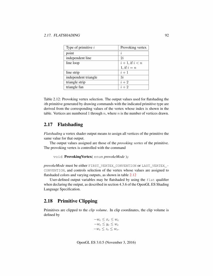
2.17. FLATSHADING 92
Type of primitive i Provoking vertexpoint i
independent line 2i
line loop i+ 1, if i < n1, if i = n
line strip i+ 1
independent triangle 3i
triangle strip i+ 2
triangle fan i+ 2
Table 2.12: Provoking vertex selection. The output values used for flatshading theith primitive generated by drawing commands with the indicated primitive type arederived from the corresponding values of the vertex whose index is shown in thetable. Vertices are numbered 1 through n, where n is the number of vertices drawn.
2.17 Flatshading
Flatshading a vertex shader output means to assign all vertices of the primitive thesame value for that output.
The output values assigned are those of the provoking vertex of the primitive.The provoking vertex is controlled with the command
void ProvokingVertex( enum provokeMode );
provokeMode must be either FIRST_VERTEX_CONVENTION or LAST_VERTEX_-CONVENTION, and controls selection of the vertex whose values are assigned toflatshaded colors and varying outputs, as shown in table 2.12
User-defined output variables may be flatshaded by using the flat qualifierwhen declaring the output, as described in section 4.3.6 of the OpenGL ES ShadingLanguage Specification.
2.18 Primitive Clipping
Primitives are clipped to the clip volume. In clip coordinates, the clip volume isdefined by
−wc ≤ xc ≤ wc
−wc ≤ yc ≤ wc
−wc ≤ zc ≤ wc.
OpenGL ES 3.0.5 (November 3, 2016)
2.18. PRIMITIVE CLIPPING 93
If the primitive under consideration is a point, then clipping passes it un-changed if it lies within the near and far clip planes; otherwise, it is discarded.
If the primitive is a line segment, then clipping does nothing to it if it liesentirely within the near and far clip planes, and discards it if it lies entirely outsidethese planes.
If part of the line segment lies between the near and far clip planes and part liesoutside, then the line segment is clipped and new vertex coordinates are computedfor one or both vertices. A clipped line segment endpoint lies on both the originalline segment and the near and/or far clip plane.
This clipping produces a value, 0 ≤ t ≤ 1, for each clipped vertex. If thecoordinates of a clipped vertex are P and the original vertices’ coordinates are P1
and P2, then t is given by
P = tP1 + (1− t)P2.
The value of t is used to clip vertex shader outputs as described in section 2.18.1.If the primitive is a polygon, then it is passed if every one of its edges lies
entirely inside the clip volume and either clipped or discarded otherwise. Polygonclipping may cause polygon edges to be clipped, but because polygon connectivitymust be maintained, these clipped edges are connected by new edges that lie alongthe clip volume’s boundary. Thus, clipping may require the introduction of newvertices into a polygon.
If it happens that a polygon intersects an edge of the clip volume’s boundary,then the clipped polygon must include a point on this boundary edge.
2.18.1 Clipping Shader Outputs
Next, vertex shader outputs are clipped. The output values associated with a vertexthat lies within the clip volume are unaffected by clipping. If a primitive is clipped,however, the output values assigned to vertices produced by clipping are clipped.
Let the output values assigned to the two vertices P1 and P2 of an unclippededge be c1 and c2. The value of t (section 2.18) for a clipped point P is used toobtain the output value associated with P as6
c = tc1 + (1− t)c2.
(Multiplying an output value by a scalar means multiplying each of x, y, z, and wby the scalar.)
6 Since this computation is performed in clip space before division by wc, clipped output valuesare perspective-correct.
OpenGL ES 3.0.5 (November 3, 2016)
2.18. PRIMITIVE CLIPPING 94
Polygon clipping may create a clipped vertex along an edge of the clip volume’sboundary. This situation is handled by noting that polygon clipping proceeds byclipping against one half-space at a time. Output value clipping is done in thesame way, so that clipped points always occur at the intersection of polygon edges(possibly already clipped) with the clip volume’s boundary.
Outputs of integer or unsigned integer type must always be declared with theflat qualifier. Since such outputs are constant over the primitive being rasterized(see sections 3.5.1 and 3.6.1), no interpolation is performed.
OpenGL ES 3.0.5 (November 3, 2016)
Chapter 3
Rasterization
Rasterization is the process by which a primitive is converted to a two-dimensionalimage. Each point of this image contains such information as color and depth.Thus, rasterizing a primitive consists of two parts. The first is to determine whichsquares of an integer grid in window coordinates are occupied by the primitive. Thesecond is assigning a depth value and one or more color values to each such square.The results of this process are passed on to the next stage of the GL (per-fragmentoperations), which uses the information to update the appropriate locations in theframebuffer. Figure 3.1 diagrams the rasterization process. The color values as-signed to a fragment are determined by a fragment shader as defined in section 3.9.The final depth value is initially determined by the rasterization operations and maybe modified or replaced by a fragment shader. The results from rasterizing a point,line, or polygon are routed through a fragment shader.
A grid square along with its z (depth) and shader output parameters is calleda fragment; the parameters are collectively dubbed the fragment’s associated data.A fragment is located by its lower left corner, which lies on integer grid coordi-nates. Rasterization operations also refer to a fragment’s center, which is offset by(1/2, 1/2) from its lower left corner (and so lies on half-integer coordinates).
Grid squares need not actually be square in the GL. Rasterization rules are notaffected by the actual aspect ratio of the grid squares. Display of non-square grids,however, will cause rasterized points and line segments to appear fatter in onedirection than the other. We assume that fragments are square, since it simplifiestexturing.
Several factors affect rasterization. Primitives may be discarded before rasteri-zation. Points may be given differing sizes and line segments differing widths.
95
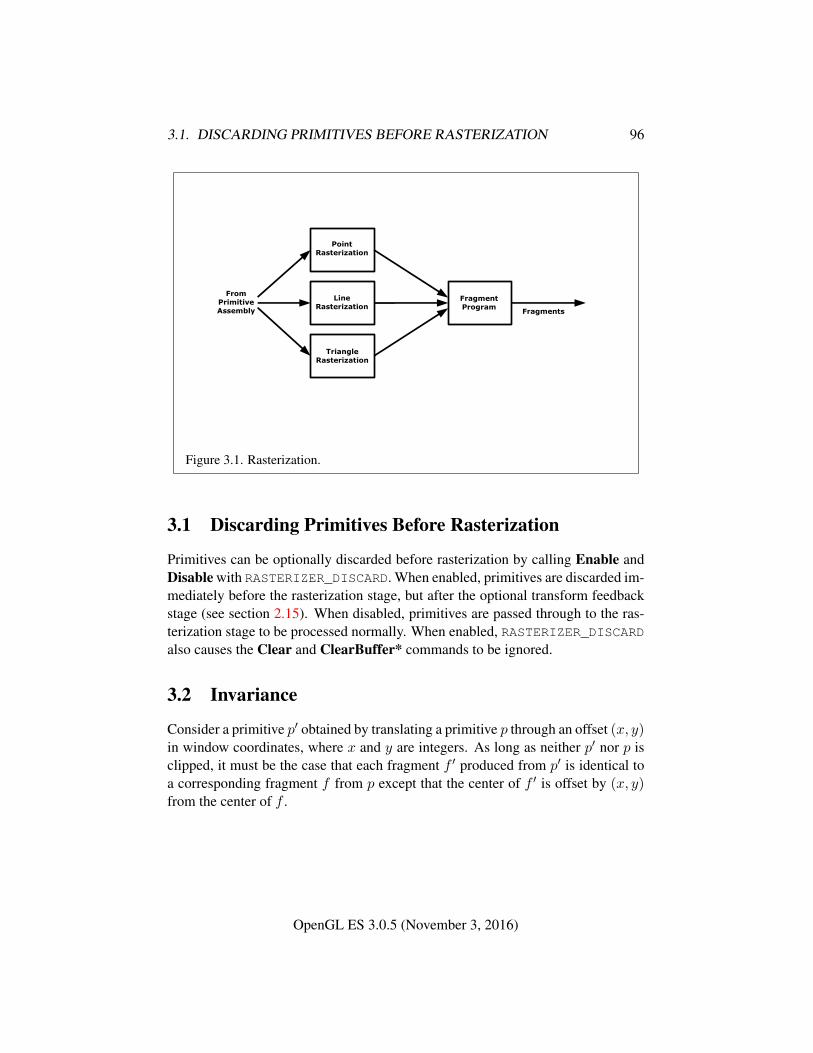
3.1. DISCARDING PRIMITIVES BEFORE RASTERIZATION 96
PointRasterization
TriangleRasterization
LineRasterization
FragmentProgram
FromPrimitiveAssembly Fragments
Figure 3.1. Rasterization.
3.1 Discarding Primitives Before Rasterization
Primitives can be optionally discarded before rasterization by calling Enable andDisable with RASTERIZER_DISCARD. When enabled, primitives are discarded im-mediately before the rasterization stage, but after the optional transform feedbackstage (see section 2.15). When disabled, primitives are passed through to the ras-terization stage to be processed normally. When enabled, RASTERIZER_DISCARDalso causes the Clear and ClearBuffer* commands to be ignored.
3.2 Invariance
Consider a primitive p′ obtained by translating a primitive p through an offset (x, y)in window coordinates, where x and y are integers. As long as neither p′ nor p isclipped, it must be the case that each fragment f ′ produced from p′ is identical toa corresponding fragment f from p except that the center of f ′ is offset by (x, y)from the center of f .
OpenGL ES 3.0.5 (November 3, 2016)
3.3. MULTISAMPLING 97
3.3 Multisampling
Multisampling is a mechanism to antialias all GL primitives: points, lines, andpolygons. The technique is to sample all primitives multiple times at each pixel.The color sample values are resolved to a single, displayable color. For windowsystem-provided framebuffers, this occurs each time a pixel is updated, so the an-tialiasing appears to be automatic at the application level. For application-createdframebuffers, this must be requested by calling the BlitFramebuffer command(see section 4.3.3). Because each sample includes color, depth, and stencil infor-mation, the color (including texture operation), depth, and stencil functions per-form equivalently to the single-sample mode.
An additional buffer, called the multisample buffer, is added to the windowsystem-provided framebuffer. Pixel sample values, including color, depth, andstencil values, are stored in this buffer. Samples contain separate color values foreach fragment color. When the window system-provided framebuffer includes amultisample buffer, it does not include depth or stencil buffers, even if the multi-sample buffer does not store depth or stencil values. Color buffers do coexist withthe multisample buffer, however.
Multisample antialiasing is most valuable for rendering polygons, because itrequires no sorting for hidden surface elimination, and it correctly handles adjacentpolygons, object silhouettes, and even intersecting polygons.
If the value of SAMPLE_BUFFERS is one, the rasterization of all primitivesis changed, and is referred to as multisample rasterization. Otherwise, primitiverasterization is referred to as single-sample rasterization. The value of SAMPLE_-BUFFERS is a framebuffer-dependent constant, and is queried by calling GetInte-gerv with pname set to SAMPLE_BUFFERS.
During multisample rendering the contents of a pixel fragment are changed intwo ways. First, each fragment includes a coverage value with SAMPLES bits. Thevalue of SAMPLES is a framebuffer-dependent constant, and is queried by callingGetIntegerv with pname set to SAMPLES.
Second, each fragment includes SAMPLES depth values and sets of associateddata, instead of the single depth value and set of associated data that is maintainedin single-sample rendering mode. An implementation may choose to assign thesame associated data to more than one sample. The location for evaluating suchassociated data can be anywhere within the pixel including the fragment center orany of the sample locations. The different associated data values need not all beevaluated at the same location. Each pixel fragment thus consists of integer x and ygrid coordinates, SAMPLES depth values and sets of associated data, and a coveragevalue with a maximum of SAMPLES bits.
Multisample rasterization is only in effect when the value of SAMPLE_-
OpenGL ES 3.0.5 (November 3, 2016)
3.4. POINTS 98
BUFFERS is one. Multisample rasterization of all primitives differs substantiallyfrom single-sample rasterization. It is understood that each pixel in the frame-buffer has SAMPLES locations associated with it. These locations are exact posi-tions, rather than regions or areas, and each is referred to as a sample point. Thesample points associated with a pixel may be located inside or outside of the unitsquare that is considered to bound the pixel. Furthermore, the relative locationsof sample points may be identical for each pixel in the framebuffer, or they maydiffer.
If the sample locations differ per pixel, they should be aligned to window, notscreen, boundaries. Otherwise rendering results will be window-position specific.The invariance requirement described in section 3.2 is relaxed for all multisamplerasterization, because the sample locations may be a function of pixel location.
3.4 Points
A point is drawn by generating a set of fragments in the shape of a square centeredaround the vertex of the point. Each vertex has an associated point size, measuredin window coordinates, that controls the size of that square.
The point size is taken from the shader built-in gl_PointSize written by thevertex shader, and clamped to the implementation-dependent point size range. Ifthe value written to gl_PointSize is less than or equal to zero, or if no valueis written, the point size is undefined. The supported range is determined by theALIASED_POINT_SIZE_RANGE and may be queried as described in chapter 6.The maximum point size supported must be at least one.
3.4.1 Basic Point Rasterization
Point rasterization produces a fragment for each framebuffer pixel whose centerlies inside a square centered at the point’s (xw, yw), with side length equal to thecurrent point size.
All fragments produced in rasterizing a point are assigned the same associ-ated data, which are those of the vertex corresponding to the point. However, thefragment shader builtin gl_PointCoord defines a per-fragment coordinate space(s, t) where s varies from 0 to 1 across the point horizontally left-to-right, and tvaries from 0 to 1 across the point vertically top-to-bottom.
The following formula is used to evaluate (s, t) values:
s =1
2+
(xf + 1
2 − xw)
size(3.1)
OpenGL ES 3.0.5 (November 3, 2016)
3.5. LINE SEGMENTS 99
t =1
2−(yf + 1
2 − yw)
size(3.2)
where size is the point’s size, xf and yf are the (integral) window coordinates ofthe fragment, and xw and yw are the exact, unrounded window coordinates of thevertex for the point.
3.4.2 Point Multisample Rasterization
If the value of SAMPLE_BUFFERS is one, then points are rasterized using the fol-lowing algorithm. Point rasterization produces a fragment for each framebufferpixel with one or more sample points that intersect a region centered at the point’s(xw, yw). This region is a square with sides equal to the current point size. Cov-erage bits that correspond to sample points that intersect the region are 1, othercoverage bits are 0. All data associated with each sample for the fragment are thedata associated with the point being rasterized.
3.5 Line Segments
A line segment results from a line strip, a line loop, or a series of separate linesegments. Line segment rasterization is controlled by several variables. Line width,which may be set by calling
void LineWidth( float width );
with an appropriate positive floating-point width, controls the width of rasterizedline segments, measured in window coordinates. The default width is 1.0. Val-ues less than or equal to 0.0 generate the error INVALID_VALUE. The supportedrange is determined by the ALIASED_LINE_WIDTH_RANGE and may be queried asdescribed in chapter 6. The maximum line width supported must be at least one.
3.5.1 Basic Line Segment Rasterization
Line segment rasterization begins by characterizing the segment as either x-majoror y-major. x-major line segments have slope in the closed interval [−1, 1]; allother line segments are y-major (slope is determined by the segment’s endpoints).We shall specify rasterization only for x-major segments except in cases where themodifications for y-major segments are not self-evident.
OpenGL ES 3.0.5 (November 3, 2016)
3.5. LINE SEGMENTS 100
Ideally, the GL uses a “diamond-exit” rule to determine those fragments thatare produced by rasterizing a line segment. For each fragment f with center at win-dow coordinates xf and yf , define a diamond-shaped region that is the intersectionof four half planes:
Rf = { (x, y) | |x− xf |+ |y − yf | < 1/2.}
Essentially, a line segment starting at pa and ending at pb produces those frag-ments f for which the segment intersects Rf , except if pb is contained in Rf . Seefigure 3.2.
To avoid difficulties when an endpoint lies on a boundary of Rf we (in princi-ple) perturb the supplied endpoints by a tiny amount. Let pa and pb have windowcoordinates (xa, ya) and (xb, yb), respectively. Obtain the perturbed endpoints p′agiven by (xa, ya) − (ε, ε2) and p′b given by (xb, yb) − (ε, ε2). Rasterizing the linesegment starting at pa and ending at pb produces those fragments f for which thesegment starting at p′a and ending on p′b intersects Rf , except if p′b is contained inRf . ε is chosen to be so small that rasterizing the line segment produces the samefragments when δ is substituted for ε for any 0 < δ ≤ ε.
When pa and pb lie on fragment centers, this characterization of fragmentsreduces to Bresenham’s algorithm with one modification: lines produced in thisdescription are “half-open,” meaning that the final fragment (corresponding to pb)is not drawn. This means that when rasterizing a series of connected line segments,shared endpoints will be produced only once rather than twice (as would occur withBresenham’s algorithm).
Because the initial and final conditions of the diamond-exit rule may be difficultto implement, other line segment rasterization algorithms are allowed, subject tothe following rules:
1. The coordinates of a fragment produced by the algorithm may not deviate bymore than one unit in either x or y window coordinates from a correspondingfragment produced by the diamond-exit rule.
2. The total number of fragments produced by the algorithm may differ fromthat produced by the diamond-exit rule by no more than one.
3. For an x-major line, no two fragments may be produced that lie in the samewindow-coordinate column (for a y-major line, no two fragments may ap-pear in the same row).
4. If two line segments share a common endpoint, and both segments are eitherx-major (both left-to-right or both right-to-left) or y-major (both bottom-to-top or both top-to-bottom), then rasterizing both segments may not produce
OpenGL ES 3.0.5 (November 3, 2016)
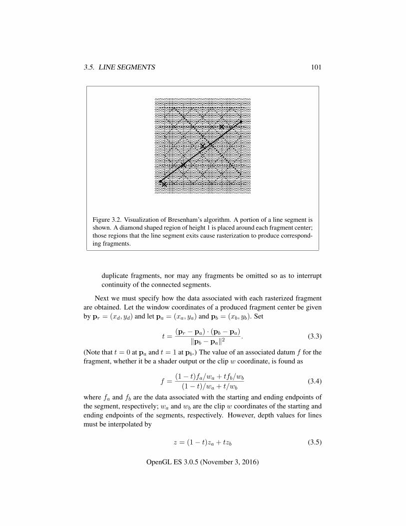
3.5. LINE SEGMENTS 101
� � � � �� � � � �� � � � �� � � � �
� � � � �� � � � �� � � � �� � � � �
� � � � �� � � � �� � � � �� � � � �
� � � � �� � � � �� � � � �� � � � �
� � � � �� � � � �� � � � �� � � � �
� � � � �� � � � �� � � � �� � � � �� � � � �� � � � �� � � � �� � � � �� � � � �� � � � �� � � � �� � � � �� � � � �� � � � �� � � � �� � � � �
� � � � �� � � � �� � � � �� � � � �� � � � �� � � � �� � � � �� � � � �
� � � � �� � � � �� � � � �� � � � �
� � � � �� � � � �� � � � �� � � � �� � � � �� � � � �� � � � �� � � � �� � � � �� � � � �� � � � �� � � � �� � � � �� � � � �� � � � �� � � � �� � � � �� � � � �� � � � �� � � � �
� � � � �� � � � �� � � � �� � � � �� � � � �� � � � �� � � � �� � � � �� � � � �� � � � �� � � � �� � � � �� � � � �� � � � �� � � � �� � � � �� � � � �� � � � �� � � � �� � � � �
Figure 3.2. Visualization of Bresenham’s algorithm. A portion of a line segment isshown. A diamond shaped region of height 1 is placed around each fragment center;those regions that the line segment exits cause rasterization to produce correspond-ing fragments.
duplicate fragments, nor may any fragments be omitted so as to interruptcontinuity of the connected segments.
Next we must specify how the data associated with each rasterized fragmentare obtained. Let the window coordinates of a produced fragment center be givenby pr = (xd, yd) and let pa = (xa, ya) and pb = (xb, yb). Set
t =(pr − pa) · (pb − pa)
‖pb − pa‖2. (3.3)
(Note that t = 0 at pa and t = 1 at pb.) The value of an associated datum f for thefragment, whether it be a shader output or the clip w coordinate, is found as
f =(1− t)fa/wa + tfb/wb
(1− t)/wa + t/wb(3.4)
where fa and fb are the data associated with the starting and ending endpoints ofthe segment, respectively; wa and wb are the clip w coordinates of the starting andending endpoints of the segments, respectively. However, depth values for linesmust be interpolated by
z = (1− t)za + tzb (3.5)
OpenGL ES 3.0.5 (November 3, 2016)
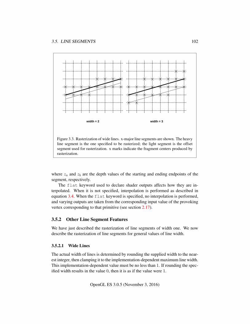
3.5. LINE SEGMENTS 102
width = 2 width = 3
Figure 3.3. Rasterization of wide lines. x-major line segments are shown. The heavyline segment is the one specified to be rasterized; the light segment is the offsetsegment used for rasterization. x marks indicate the fragment centers produced byrasterization.
where za and zb are the depth values of the starting and ending endpoints of thesegment, respectively.
The flat keyword used to declare shader outputs affects how they are in-terpolated. When it is not specified, interpolation is performed as described inequation 3.4. When the flat keyword is specified, no interpolation is performed,and varying outputs are taken from the corresponding input value of the provokingvertex corresponding to that primitive (see section 2.17).
3.5.2 Other Line Segment Features
We have just described the rasterization of line segments of width one. We nowdescribe the rasterization of line segments for general values of line width.
3.5.2.1 Wide Lines
The actual width of lines is determined by rounding the supplied width to the near-est integer, then clamping it to the implementation-dependent maximum line width.This implementation-dependent value must be no less than 1. If rounding the spec-ified width results in the value 0, then it is as if the value were 1.
OpenGL ES 3.0.5 (November 3, 2016)
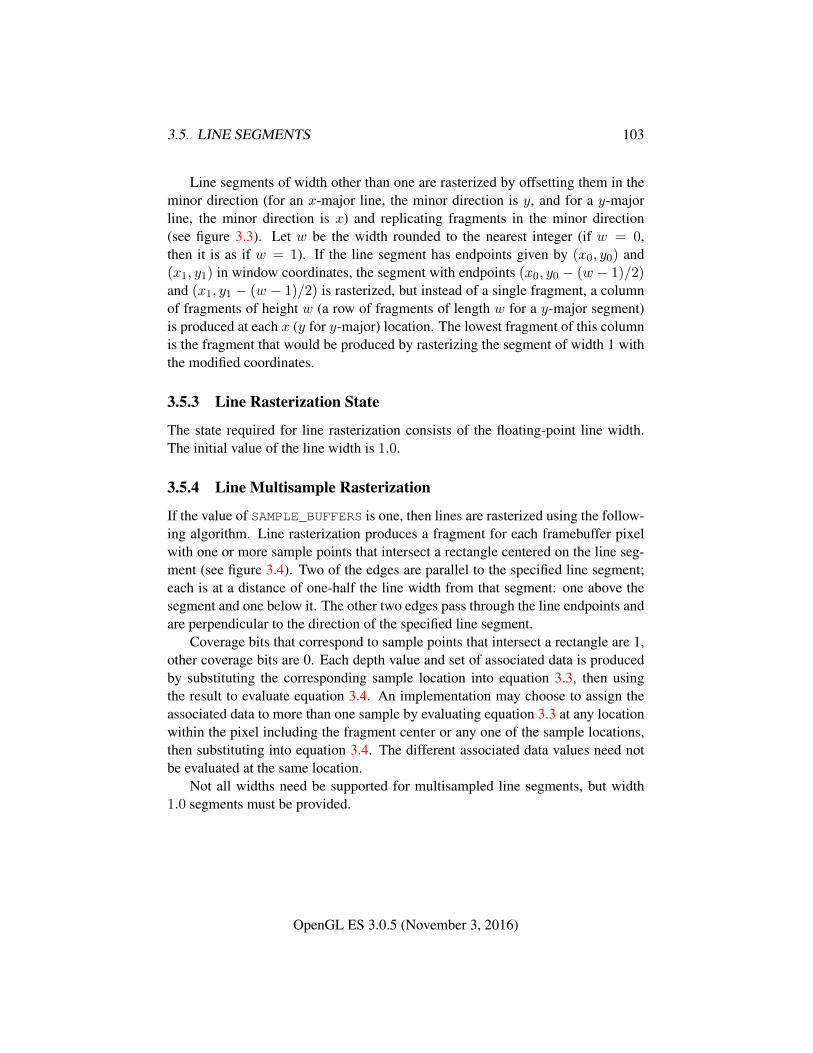
3.5. LINE SEGMENTS 103
Line segments of width other than one are rasterized by offsetting them in theminor direction (for an x-major line, the minor direction is y, and for a y-majorline, the minor direction is x) and replicating fragments in the minor direction(see figure 3.3). Let w be the width rounded to the nearest integer (if w = 0,then it is as if w = 1). If the line segment has endpoints given by (x0, y0) and(x1, y1) in window coordinates, the segment with endpoints (x0, y0 − (w − 1)/2)and (x1, y1 − (w − 1)/2) is rasterized, but instead of a single fragment, a columnof fragments of height w (a row of fragments of length w for a y-major segment)is produced at each x (y for y-major) location. The lowest fragment of this columnis the fragment that would be produced by rasterizing the segment of width 1 withthe modified coordinates.
3.5.3 Line Rasterization State
The state required for line rasterization consists of the floating-point line width.The initial value of the line width is 1.0.
3.5.4 Line Multisample Rasterization
If the value of SAMPLE_BUFFERS is one, then lines are rasterized using the follow-ing algorithm. Line rasterization produces a fragment for each framebuffer pixelwith one or more sample points that intersect a rectangle centered on the line seg-ment (see figure 3.4). Two of the edges are parallel to the specified line segment;each is at a distance of one-half the line width from that segment: one above thesegment and one below it. The other two edges pass through the line endpoints andare perpendicular to the direction of the specified line segment.
Coverage bits that correspond to sample points that intersect a rectangle are 1,other coverage bits are 0. Each depth value and set of associated data is producedby substituting the corresponding sample location into equation 3.3, then usingthe result to evaluate equation 3.4. An implementation may choose to assign theassociated data to more than one sample by evaluating equation 3.3 at any locationwithin the pixel including the fragment center or any one of the sample locations,then substituting into equation 3.4. The different associated data values need notbe evaluated at the same location.
Not all widths need be supported for multisampled line segments, but width1.0 segments must be provided.
OpenGL ES 3.0.5 (November 3, 2016)
3.6. POLYGONS 104
� � � � � � � � � � � � � � � � � � � �� � � � � � � � � � � � � � � � � � � �� � � � � � � � � � � � � � � � � � � �� � � � � � � � � � � � � � � � � � � �� � � � � � � � � � � � � � � � � � � �� � � � � � � � � � � � � � � � � � � �� � � � � � � � � � � � � � � � � � � �� � � � � � � � � � � � � � � � � � � �� � � � � � � � � � � � � � � � � � � �� � � � � � � � � � � � � � � � � � � �� � � � � � � � � � � � � � � � � � � �� � � � � � � � � � � � � � � � � � � �� � � � � � � � � � � � � � � � � � � �� � � � � � � � � � � � � � � � � � � �
Figure 3.4. The region used in rasterizing a multisampled line segment (an x-majorline segment is shown).
3.6 Polygons
A polygon results from a triangle arising from a triangle strip, triangle fan, or seriesof separate triangles.
3.6.1 Basic Polygon Rasterization
The first step of polygon rasterization is to determine if the polygon is back-facingor front-facing. This determination is made based on the sign of the (clipped orunclipped) polygon’s area computed in window coordinates. One way to computethis area is
a =1
2
n−1∑i=0
xiwyi⊕1w − xi⊕1w yiw (3.6)
where xiw and yiw are the x and y window coordinates of the ith vertex ofthe n-vertex polygon (vertices are numbered starting at zero for purposes of thiscomputation) and i⊕1 is (i+1) mod n. The interpretation of the sign of this valueis controlled with
void FrontFace( enum dir );
OpenGL ES 3.0.5 (November 3, 2016)
3.6. POLYGONS 105
Setting dir to CCW (corresponding to counter-clockwise orientation of the pro-jected polygon in window coordinates) uses a as computed above. Setting dir toCW (corresponding to clockwise orientation) indicates that the sign of a should bereversed prior to use. Front face determination requires one bit of state, and isinitially set to CCW.
If the sign of a (including the possible reversal of this sign as determined byFrontFace) is positive, the polygon is front-facing; otherwise, it is back-facing.This determination is used in conjunction with the CullFace enable bit and modevalue to decide whether or not a particular polygon is rasterized. The CullFacemode is set by calling
void CullFace( enum mode );
mode is a symbolic constant: one of FRONT, BACK or FRONT_AND_BACK. Cullingis enabled or disabled with Enable or Disable using the symbolic constant CULL_-FACE. Front-facing polygons are rasterized if either culling is disabled or the Cull-Face mode is BACK while back-facing polygons are rasterized only if either cullingis disabled or the CullFace mode is FRONT. The initial setting of the CullFacemode is BACK. Initially, culling is disabled.
The rule for determining which fragments are produced by polygon rasteriza-tion is called point sampling. The two-dimensional projection obtained by takingthe x and y window coordinates of the polygon’s vertices is formed. Fragmentcenters that lie inside of this polygon are produced by rasterization. Special treat-ment is given to a fragment whose center lies on a polygon edge. In such a casewe require that if two polygons lie on either side of a common edge (with identicalendpoints) on which a fragment center lies, then exactly one of the polygons resultsin the production of the fragment during rasterization.
As for the data associated with each fragment produced by rasterizing a poly-gon, we begin by specifying how these values are produced for fragments in atriangle. Define barycentric coordinates for a triangle. Barycentric coordinates area set of three numbers, a, b, and c, each in the range [0, 1], with a + b + c = 1.These coordinates uniquely specify any point p within the triangle or on the trian-gle’s boundary as
p = apa + bpb + cpc,
where pa, pb, and pc are the vertices of the triangle. a, b, and c can be found as
a =A(ppbpc)
A(papbpc), b =
A(ppapc)
A(papbpc), c =
A(ppapb)
A(papbpc),
where A(lmn) denotes the area in window coordinates of the triangle with verticesl, m, and n.
OpenGL ES 3.0.5 (November 3, 2016)
3.6. POLYGONS 106
Denote an associated datum at pa, pb, or pc as fa, fb, or fc, respectively. Thenthe value f of a datum at a fragment produced by rasterizing a triangle is given by
f =afa/wa + bfb/wb + cfc/wc
a/wa + b/wb + c/wc(3.7)
where wa, wb and wc are the clip w coordinates of pa, pb, and pc, respectively.a, b, and c are the barycentric coordinates of the fragment for which the data areproduced. a, b, and c must correspond precisely to the exact coordinates of thecenter of the fragment. Another way of saying this is that the data associated witha fragment must be sampled at the fragment’s center. However, depth values forpolygons must be interpolated by
z = aza + bzb + czc (3.8)
where za, zb, and zc are the depth values of pa, pb, and pc, respectively.The flat keyword used to declare shader outputs affects how they are in-
terpolated. When it is not specified, interpolation is performed as described inequation 3.7. When the flat keyword is specified, no interpolation is performed,and outputs are taken from the corresponding input value of the provoking vertexcorresponding to that primitive (see section 2.17).
For a polygon with more than three edges, such as may be produced by clippinga triangle, we require only that a convex combination of the values of the datumat the polygon’s vertices can be used to obtain the value assigned to each fragmentproduced by the rasterization algorithm. That is, it must be the case that at everyfragment
f =n∑
i=1
aifi
where n is the number of vertices in the polygon, fi is the value of the f at vertexi; for each i 0 ≤ ai ≤ 1 and
∑ni=1 ai = 1. The values of the ai may differ from
fragment to fragment, but at vertex i, aj = 0, j 6= i and ai = 1.One algorithm that achieves the required behavior is to triangulate a polygon
(without adding any vertices) and then treat each triangle individually as alreadydiscussed. A scan-line rasterizer that linearly interpolates data along each edgeand then linearly interpolates data across each horizontal span from edge to edgealso satisfies the restrictions (in this case, the numerator and denominator of equa-tion 3.7 should be iterated independently and a division performed for each frag-ment).
OpenGL ES 3.0.5 (November 3, 2016)
3.6. POLYGONS 107
3.6.2 Depth Offset
The depth values of all fragments generated by the rasterization of a polygon maybe offset by a single value that is computed for that polygon. The function thatdetermines this value is specified by calling
void PolygonOffset( float factor, float units );
factor scales the maximum depth slope of the polygon, and units scales animplementation-dependent constant that relates to the usable resolution of thedepth buffer. The resulting values are summed to produce the polygon offset value.Both factor and units may be either positive or negative.
The maximum depth slope m of a triangle is
m =
√(∂zw∂xw
)2
+
(∂zw∂yw
)2
(3.9)
where (xw, yw, zw) is a point on the triangle. m may be approximated as
m = max
{∣∣∣∣ ∂zw∂xw
∣∣∣∣ , ∣∣∣∣∂zw∂yw
∣∣∣∣} . (3.10)
The minimum resolvable difference r is an implementation-dependent param-eter that depends on the depth buffer representation. It is the smallest difference inwindow coordinate z values that is guaranteed to remain distinct throughout poly-gon rasterization and in the depth buffer. All pairs of fragments generated by therasterization of two polygons with otherwise identical vertices, but zw values thatdiffer by r, will have distinct depth values.
For fixed-point depth buffer representations, r is constant throughout the rangeof the entire depth buffer. For floating-point depth buffers, there is no single min-imum resolvable difference. In this case, the minimum resolvable difference for agiven polygon is dependent on the maximum exponent, e, in the range of z valuesspanned by the primitive. If n is the number of bits in the floating-point mantissa,the minimum resolvable difference, r, for the given primitive is defined as
r = 2e−n.
If no depth buffer is present, r is undefined.The offset value o for a polygon is
o = m× factor + r × units. (3.11)
OpenGL ES 3.0.5 (November 3, 2016)
3.7. PIXEL RECTANGLES 108
m is computed as described above. If the depth buffer uses a fixed-point represen-tation, m is a function of depth values in the range [0, 1], and o is applied to depthvalues in the same range.
Boolean state value POLYGON_OFFSET_FILL determines whether o is appliedduring the rasterization of polygons. This boolean state value is enabled and dis-abled with the commands Enable and Disable.
For fixed-point depth buffers, fragment depth values are always limited to therange [0, 1] by clamping after offset addition is performed. Fragment depth valuesare clamped even when the depth buffer uses a floating-point representation.
3.6.3 Polygon Multisample Rasterization
If the value of SAMPLE_BUFFERS is one, then polygons are rasterized using thefollowing algorithm. Polygon rasterization produces a fragment for each frame-buffer pixel with one or more sample points that satisfy the point sampling criteriadescribed in section 3.6.1. If a polygon is culled, based on its orientation and theCullFace mode, then no fragments are produced during rasterization.
Coverage bits that correspond to sample points that satisfy the point samplingcriteria are 1, other coverage bits are 0. Each associated datum is produced asdescribed in section 3.6.1, but using the corresponding sample location instead ofthe fragment center. An implementation may choose to assign the same associateddata values to more than one sample by barycentric evaluation using any locationwithin the pixel including the fragment center or one of the sample locations.
The flat qualifier affects how shader outputs are interpolated in the samefashion as described for basic polygon rasterization in section 3.6.1.
3.6.4 Polygon Rasterization State
The state required for polygon rasterization consists of whether polygon offsets areenabled or disabled, and the factor and bias values of the polygon offset equation.The initial polygon offset factor and bias values are both 0; initially polygon offsetis disabled.
3.7 Pixel Rectangles
Rectangles of color, depth, and certain other values may be specified to the GLusing TexImage*D (see section 3.8.3). Some of the parameters and operationsgoverning the operation of these commands are shared by ReadPixels (used to ob-tain pixel values from the framebuffer); the discussion of ReadPixels, however, is
OpenGL ES 3.0.5 (November 3, 2016)
3.7. PIXEL RECTANGLES 109
Parameter Name Type Initial Value Valid RangeUNPACK_ROW_LENGTH integer 0 [0,∞)
UNPACK_SKIP_ROWS integer 0 [0,∞)
UNPACK_SKIP_PIXELS integer 0 [0,∞)
UNPACK_ALIGNMENT integer 4 1,2,4,8UNPACK_IMAGE_HEIGHT integer 0 [0,∞)
UNPACK_SKIP_IMAGES integer 0 [0,∞)
Table 3.1: PixelStorei parameters pertaining to one or more of TexImage2D, Tex-Image3D, TexSubImage2D, and TexSubImage3D.
deferred until chapter 4 after the framebuffer has been discussed in detail. Nev-ertheless, we note in this section when parameters and state pertaining to thesecommands also pertain to ReadPixels.
A number of parameters control the encoding of pixels in buffer object or clientmemory (for reading and writing) and how pixels are processed before being placedin or after being read from the framebuffer (for reading, writing, and copying).These parameters are set with PixelStorei.
3.7.1 Pixel Storage Modes and Pixel Buffer Objects
Pixel storage modes affect the operation of TexImage*D, TexSubImage*D, andReadPixels when one of these commands is issued. Pixel storage modes are setwith
void PixelStorei( enum pname, int param );
pname is a symbolic constant indicating a parameter to be set, and param is thevalue to set it to. Tables 3.1 and 4.4 summarize the pixel storage parameters, theirtypes, their initial values, and their allowable ranges. Setting a parameter to a valueoutside the given range results in the error INVALID_VALUE.
In addition to storing pixel data in client memory, pixel data may also bestored in buffer objects (described in section 2.10). The current pixel unpack andpack buffer objects are designated by the PIXEL_UNPACK_BUFFER and PIXEL_-
PACK_BUFFER targets respectively.Initially, zero is bound for the PIXEL_UNPACK_BUFFER, indicating that im-
age specification commands such as TexImage*D source their pixels from clientmemory pointer parameters. However, if a non-zero buffer object is bound as thecurrent pixel unpack buffer, then the pointer parameter is treated as an offset intothe designated buffer object.
OpenGL ES 3.0.5 (November 3, 2016)
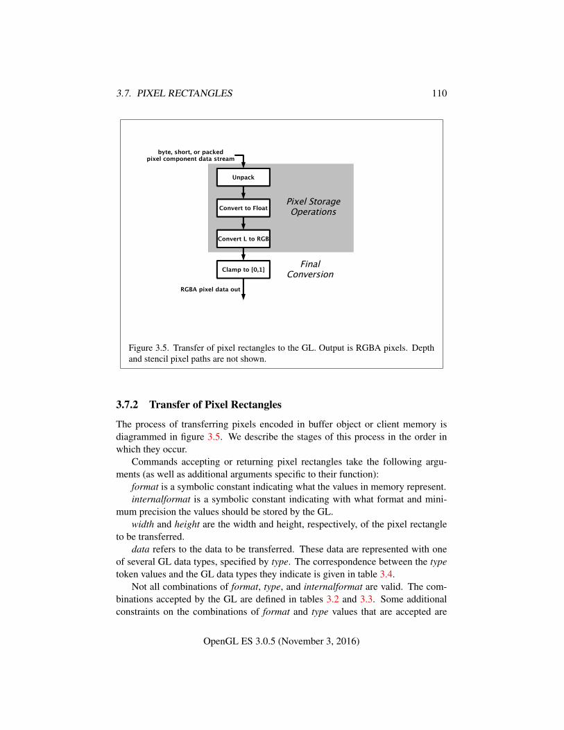
3.7. PIXEL RECTANGLES 110
Unpack
byte, short, or packedpixel component data stream
Convert to Float
Convert L to RGB
Clamp to [0,1]
RGBA pixel data out
Pixel StorageOperations
FinalConversion
Figure 3.5. Transfer of pixel rectangles to the GL. Output is RGBA pixels. Depthand stencil pixel paths are not shown.
3.7.2 Transfer of Pixel Rectangles
The process of transferring pixels encoded in buffer object or client memory isdiagrammed in figure 3.5. We describe the stages of this process in the order inwhich they occur.
Commands accepting or returning pixel rectangles take the following argu-ments (as well as additional arguments specific to their function):
format is a symbolic constant indicating what the values in memory represent.internalformat is a symbolic constant indicating with what format and mini-
mum precision the values should be stored by the GL.width and height are the width and height, respectively, of the pixel rectangle
to be transferred.data refers to the data to be transferred. These data are represented with one
of several GL data types, specified by type. The correspondence between the typetoken values and the GL data types they indicate is given in table 3.4.
Not all combinations of format, type, and internalformat are valid. The com-binations accepted by the GL are defined in tables 3.2 and 3.3. Some additionalconstraints on the combinations of format and type values that are accepted are
OpenGL ES 3.0.5 (November 3, 2016)
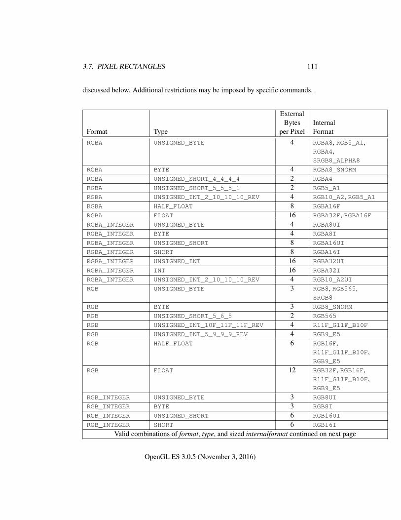
3.7. PIXEL RECTANGLES 111
discussed below. Additional restrictions may be imposed by specific commands.
ExternalBytes Internal
Format Type per Pixel FormatRGBA UNSIGNED_BYTE 4 RGBA8, RGB5_A1,
RGBA4,SRGB8_ALPHA8
RGBA BYTE 4 RGBA8_SNORM
RGBA UNSIGNED_SHORT_4_4_4_4 2 RGBA4
RGBA UNSIGNED_SHORT_5_5_5_1 2 RGB5_A1
RGBA UNSIGNED_INT_2_10_10_10_REV 4 RGB10_A2, RGB5_A1RGBA HALF_FLOAT 8 RGBA16F
RGBA FLOAT 16 RGBA32F, RGBA16FRGBA_INTEGER UNSIGNED_BYTE 4 RGBA8UI
RGBA_INTEGER BYTE 4 RGBA8I
RGBA_INTEGER UNSIGNED_SHORT 8 RGBA16UI
RGBA_INTEGER SHORT 8 RGBA16I
RGBA_INTEGER UNSIGNED_INT 16 RGBA32UI
RGBA_INTEGER INT 16 RGBA32I
RGBA_INTEGER UNSIGNED_INT_2_10_10_10_REV 4 RGB10_A2UI
RGB UNSIGNED_BYTE 3 RGB8, RGB565,SRGB8
RGB BYTE 3 RGB8_SNORM
RGB UNSIGNED_SHORT_5_6_5 2 RGB565
RGB UNSIGNED_INT_10F_11F_11F_REV 4 R11F_G11F_B10F
RGB UNSIGNED_INT_5_9_9_9_REV 4 RGB9_E5
RGB HALF_FLOAT 6 RGB16F,R11F_G11F_B10F,RGB9_E5
RGB FLOAT 12 RGB32F, RGB16F,R11F_G11F_B10F,RGB9_E5
RGB_INTEGER UNSIGNED_BYTE 3 RGB8UI
RGB_INTEGER BYTE 3 RGB8I
RGB_INTEGER UNSIGNED_SHORT 6 RGB16UI
RGB_INTEGER SHORT 6 RGB16I
Valid combinations of format, type, and sized internalformat continued on next page
OpenGL ES 3.0.5 (November 3, 2016)
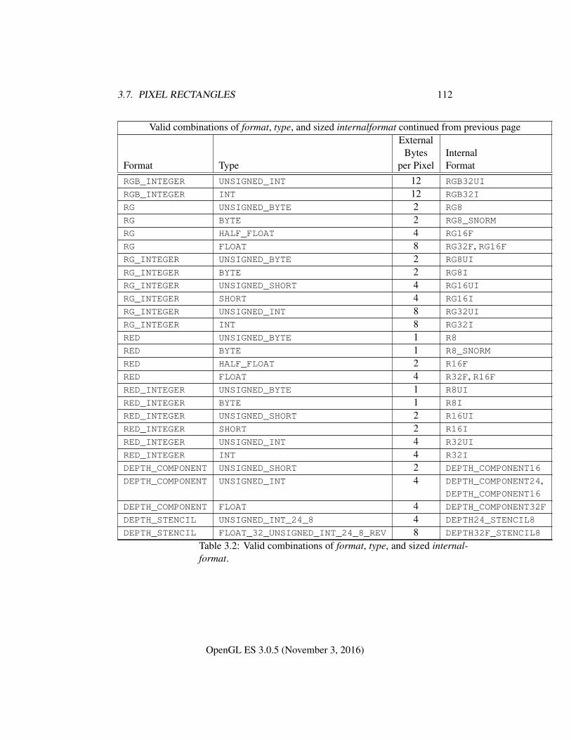
3.7. PIXEL RECTANGLES 112
Valid combinations of format, type, and sized internalformat continued from previous pageExternal
Bytes InternalFormat Type per Pixel FormatRGB_INTEGER UNSIGNED_INT 12 RGB32UI
RGB_INTEGER INT 12 RGB32I
RG UNSIGNED_BYTE 2 RG8
RG BYTE 2 RG8_SNORM
RG HALF_FLOAT 4 RG16F
RG FLOAT 8 RG32F, RG16FRG_INTEGER UNSIGNED_BYTE 2 RG8UI
RG_INTEGER BYTE 2 RG8I
RG_INTEGER UNSIGNED_SHORT 4 RG16UI
RG_INTEGER SHORT 4 RG16I
RG_INTEGER UNSIGNED_INT 8 RG32UI
RG_INTEGER INT 8 RG32I
RED UNSIGNED_BYTE 1 R8
RED BYTE 1 R8_SNORM
RED HALF_FLOAT 2 R16F
RED FLOAT 4 R32F, R16FRED_INTEGER UNSIGNED_BYTE 1 R8UI
RED_INTEGER BYTE 1 R8I
RED_INTEGER UNSIGNED_SHORT 2 R16UI
RED_INTEGER SHORT 2 R16I
RED_INTEGER UNSIGNED_INT 4 R32UI
RED_INTEGER INT 4 R32I
DEPTH_COMPONENT UNSIGNED_SHORT 2 DEPTH_COMPONENT16
DEPTH_COMPONENT UNSIGNED_INT 4 DEPTH_COMPONENT24,DEPTH_COMPONENT16
DEPTH_COMPONENT FLOAT 4 DEPTH_COMPONENT32F
DEPTH_STENCIL UNSIGNED_INT_24_8 4 DEPTH24_STENCIL8
DEPTH_STENCIL FLOAT_32_UNSIGNED_INT_24_8_REV 8 DEPTH32F_STENCIL8
Table 3.2: Valid combinations of format, type, and sized internal-format.
OpenGL ES 3.0.5 (November 3, 2016)
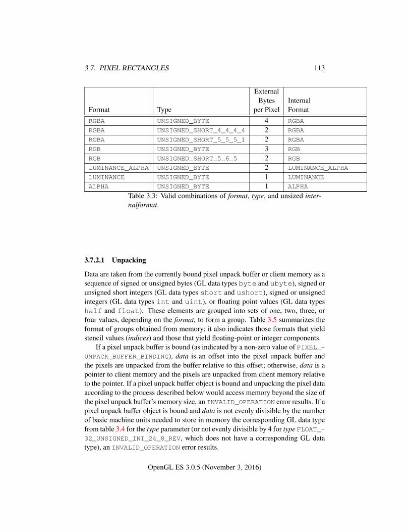
3.7. PIXEL RECTANGLES 113
ExternalBytes Internal
Format Type per Pixel FormatRGBA UNSIGNED_BYTE 4 RGBA
RGBA UNSIGNED_SHORT_4_4_4_4 2 RGBA
RGBA UNSIGNED_SHORT_5_5_5_1 2 RGBA
RGB UNSIGNED_BYTE 3 RGB
RGB UNSIGNED_SHORT_5_6_5 2 RGB
LUMINANCE_ALPHA UNSIGNED_BYTE 2 LUMINANCE_ALPHA
LUMINANCE UNSIGNED_BYTE 1 LUMINANCE
ALPHA UNSIGNED_BYTE 1 ALPHA
Table 3.3: Valid combinations of format, type, and unsized inter-nalformat.
3.7.2.1 Unpacking
Data are taken from the currently bound pixel unpack buffer or client memory as asequence of signed or unsigned bytes (GL data types byte and ubyte), signed orunsigned short integers (GL data types short and ushort), signed or unsignedintegers (GL data types int and uint), or floating point values (GL data typeshalf and float). These elements are grouped into sets of one, two, three, orfour values, depending on the format, to form a group. Table 3.5 summarizes theformat of groups obtained from memory; it also indicates those formats that yieldstencil values (indices) and those that yield floating-point or integer components.
If a pixel unpack buffer is bound (as indicated by a non-zero value of PIXEL_-UNPACK_BUFFER_BINDING), data is an offset into the pixel unpack buffer andthe pixels are unpacked from the buffer relative to this offset; otherwise, data is apointer to client memory and the pixels are unpacked from client memory relativeto the pointer. If a pixel unpack buffer object is bound and unpacking the pixel dataaccording to the process described below would access memory beyond the size ofthe pixel unpack buffer’s memory size, an INVALID_OPERATION error results. If apixel unpack buffer object is bound and data is not evenly divisible by the numberof basic machine units needed to store in memory the corresponding GL data typefrom table 3.4 for the type parameter (or not evenly divisible by 4 for type FLOAT_-32_UNSIGNED_INT_24_8_REV, which does not have a corresponding GL datatype), an INVALID_OPERATION error results.
OpenGL ES 3.0.5 (November 3, 2016)
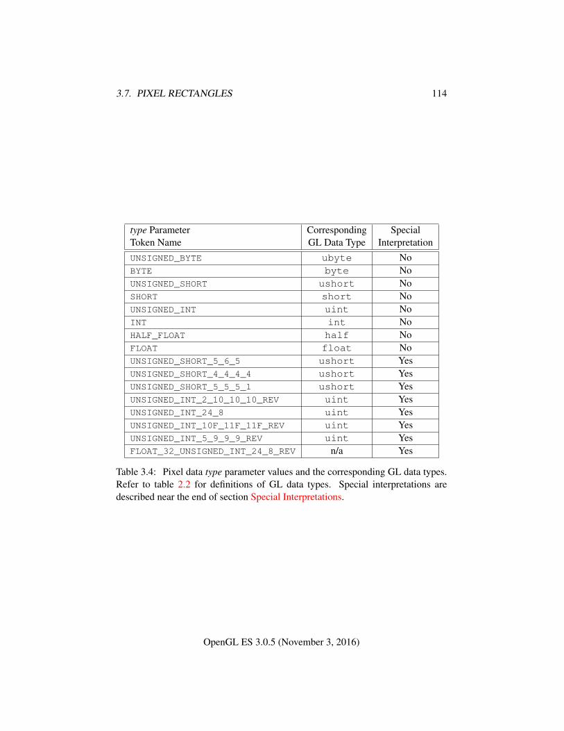
3.7. PIXEL RECTANGLES 114
type Parameter Corresponding SpecialToken Name GL Data Type InterpretationUNSIGNED_BYTE ubyte NoBYTE byte NoUNSIGNED_SHORT ushort NoSHORT short NoUNSIGNED_INT uint NoINT int NoHALF_FLOAT half NoFLOAT float NoUNSIGNED_SHORT_5_6_5 ushort YesUNSIGNED_SHORT_4_4_4_4 ushort YesUNSIGNED_SHORT_5_5_5_1 ushort YesUNSIGNED_INT_2_10_10_10_REV uint YesUNSIGNED_INT_24_8 uint YesUNSIGNED_INT_10F_11F_11F_REV uint YesUNSIGNED_INT_5_9_9_9_REV uint YesFLOAT_32_UNSIGNED_INT_24_8_REV n/a Yes
Table 3.4: Pixel data type parameter values and the corresponding GL data types.Refer to table 2.2 for definitions of GL data types. Special interpretations aredescribed near the end of section Special Interpretations.
OpenGL ES 3.0.5 (November 3, 2016)
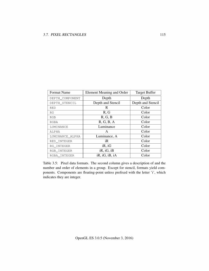
3.7. PIXEL RECTANGLES 115
Format Name Element Meaning and Order Target BufferDEPTH_COMPONENT Depth DepthDEPTH_STENCIL Depth and Stencil Depth and StencilRED R ColorRG R, G ColorRGB R, G, B ColorRGBA R, G, B, A ColorLUMINANCE Luminance ColorALPHA A ColorLUMINANCE_ALPHA Luminance, A ColorRED_INTEGER iR ColorRG_INTEGER iR, iG ColorRGB_INTEGER iR, iG, iB ColorRGBA_INTEGER iR, iG, iB, iA Color
Table 3.5: Pixel data formats. The second column gives a description of and thenumber and order of elements in a group. Except for stencil, formats yield com-ponents. Components are floating-point unless prefixed with the letter ’i’, whichindicates they are integer.
OpenGL ES 3.0.5 (November 3, 2016)
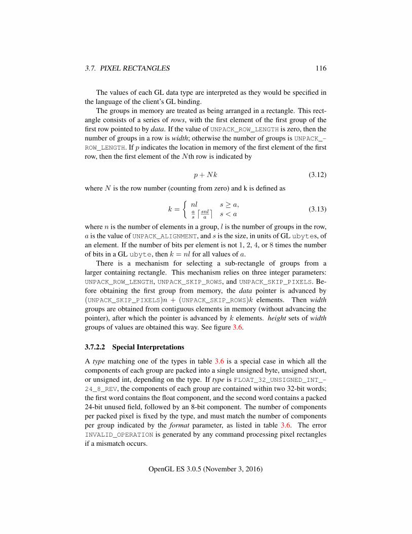
3.7. PIXEL RECTANGLES 116
The values of each GL data type are interpreted as they would be specified inthe language of the client’s GL binding.
The groups in memory are treated as being arranged in a rectangle. This rect-angle consists of a series of rows, with the first element of the first group of thefirst row pointed to by data. If the value of UNPACK_ROW_LENGTH is zero, then thenumber of groups in a row is width; otherwise the number of groups is UNPACK_-ROW_LENGTH. If p indicates the location in memory of the first element of the firstrow, then the first element of the N th row is indicated by
p+Nk (3.12)
where N is the row number (counting from zero) and k is defined as
k =
{nl s ≥ a,as
⌈snla
⌉s < a
(3.13)
where n is the number of elements in a group, l is the number of groups in the row,a is the value of UNPACK_ALIGNMENT, and s is the size, in units of GL ubytes, ofan element. If the number of bits per element is not 1, 2, 4, or 8 times the numberof bits in a GL ubyte, then k = nl for all values of a.
There is a mechanism for selecting a sub-rectangle of groups from alarger containing rectangle. This mechanism relies on three integer parameters:UNPACK_ROW_LENGTH, UNPACK_SKIP_ROWS, and UNPACK_SKIP_PIXELS. Be-fore obtaining the first group from memory, the data pointer is advanced by(UNPACK_SKIP_PIXELS)n + (UNPACK_SKIP_ROWS)k elements. Then widthgroups are obtained from contiguous elements in memory (without advancing thepointer), after which the pointer is advanced by k elements. height sets of widthgroups of values are obtained this way. See figure 3.6.
3.7.2.2 Special Interpretations
A type matching one of the types in table 3.6 is a special case in which all thecomponents of each group are packed into a single unsigned byte, unsigned short,or unsigned int, depending on the type. If type is FLOAT_32_UNSIGNED_INT_-24_8_REV, the components of each group are contained within two 32-bit words;the first word contains the float component, and the second word contains a packed24-bit unused field, followed by an 8-bit component. The number of componentsper packed pixel is fixed by the type, and must match the number of componentsper group indicated by the format parameter, as listed in table 3.6. The errorINVALID_OPERATION is generated by any command processing pixel rectanglesif a mismatch occurs.
OpenGL ES 3.0.5 (November 3, 2016)
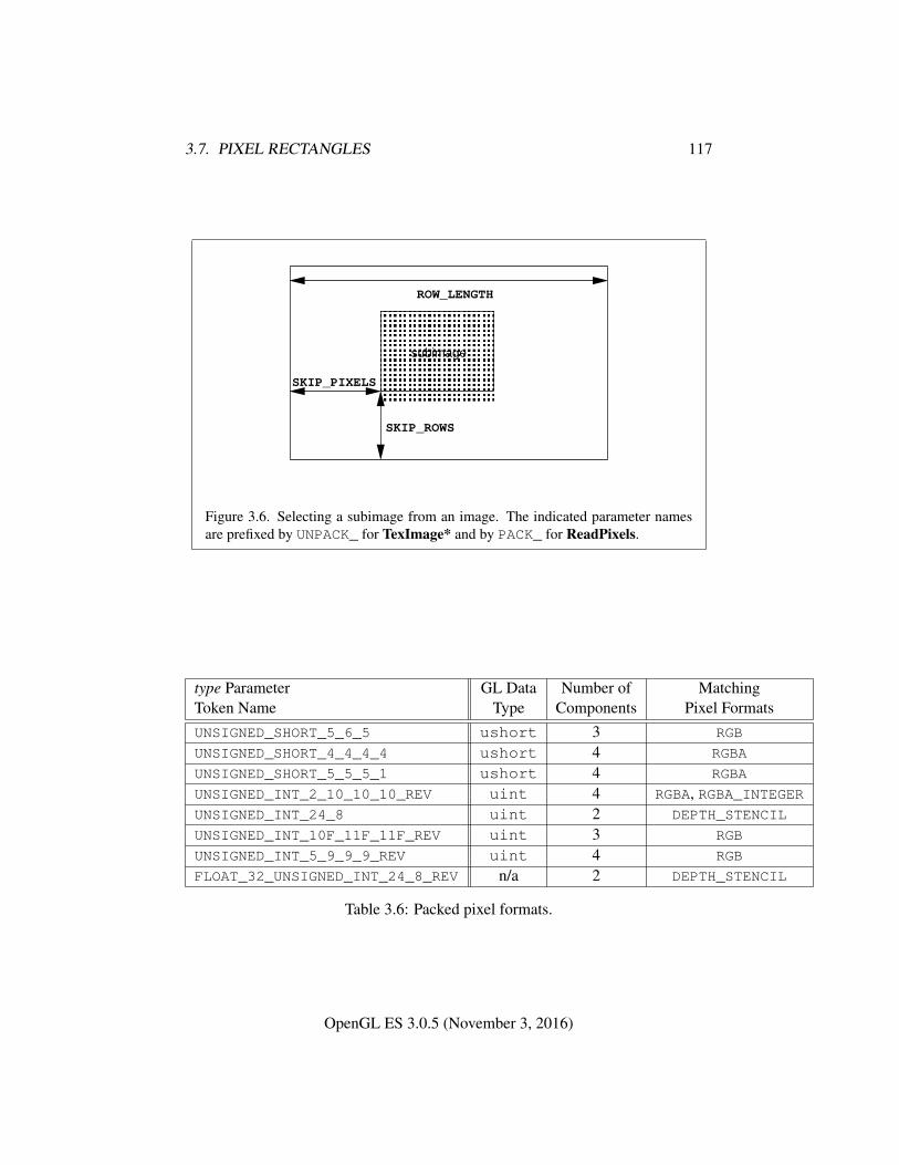
3.7. PIXEL RECTANGLES 117
� � � � � � � � � �� � � � � � � � � �� � � � � � � � � �� � � � � � � � � �� � � � � � � � � �� � � � � � � � � �� � � � � � � � � �� � � � � � � � � �
SKIP_ROWS
SKIP_PIXELS
ROW_LENGTH
subimage
Figure 3.6. Selecting a subimage from an image. The indicated parameter namesare prefixed by UNPACK_ for TexImage* and by PACK_ for ReadPixels.
type Parameter GL Data Number of MatchingToken Name Type Components Pixel FormatsUNSIGNED_SHORT_5_6_5 ushort 3 RGB
UNSIGNED_SHORT_4_4_4_4 ushort 4 RGBA
UNSIGNED_SHORT_5_5_5_1 ushort 4 RGBA
UNSIGNED_INT_2_10_10_10_REV uint 4 RGBA, RGBA_INTEGERUNSIGNED_INT_24_8 uint 2 DEPTH_STENCIL
UNSIGNED_INT_10F_11F_11F_REV uint 3 RGB
UNSIGNED_INT_5_9_9_9_REV uint 4 RGB
FLOAT_32_UNSIGNED_INT_24_8_REV n/a 2 DEPTH_STENCIL
Table 3.6: Packed pixel formats.
OpenGL ES 3.0.5 (November 3, 2016)
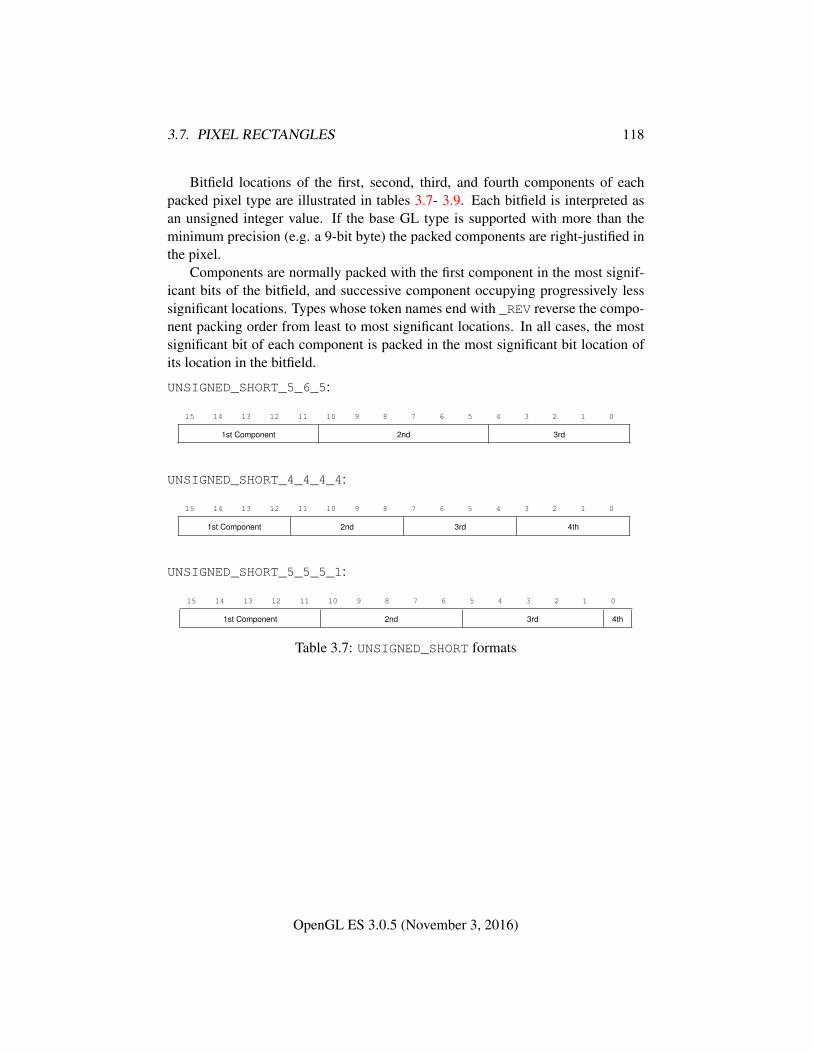
3.7. PIXEL RECTANGLES 118
Bitfield locations of the first, second, third, and fourth components of eachpacked pixel type are illustrated in tables 3.7- 3.9. Each bitfield is interpreted asan unsigned integer value. If the base GL type is supported with more than theminimum precision (e.g. a 9-bit byte) the packed components are right-justified inthe pixel.
Components are normally packed with the first component in the most signif-icant bits of the bitfield, and successive component occupying progressively lesssignificant locations. Types whose token names end with _REV reverse the compo-nent packing order from least to most significant locations. In all cases, the mostsignificant bit of each component is packed in the most significant bit location ofits location in the bitfield.
UNSIGNED_SHORT_5_6_5:
15 14 13 12 11 10 9 8 7 6 5 4 3 2 1 0
1st Component 2nd 3rd
UNSIGNED_SHORT_4_4_4_4:
15 14 13 12 11 10 9 8 7 6 5 4 3 2 1 0
1st Component 2nd 3rd 4th
UNSIGNED_SHORT_5_5_5_1:
15 14 13 12 11 10 9 8 7 6 5 4 3 2 1 0
1st Component 2nd 3rd 4th
Table 3.7: UNSIGNED_SHORT formats
OpenGL ES 3.0.5 (November 3, 2016)
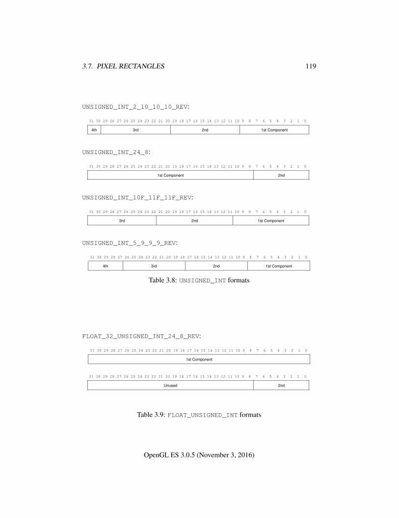
3.7. PIXEL RECTANGLES 119
UNSIGNED_INT_2_10_10_10_REV:
31 30 29 28 27 26 25 24 23 22 21 20 19 18 17 16 15 14 13 12 11 10 9 8 7 6 5 4 3 2 1 0
4th 3rd 2nd 1st Component
UNSIGNED_INT_24_8:
31 30 29 28 27 26 25 24 23 22 21 20 19 18 17 16 15 14 13 12 11 10 9 8 7 6 5 4 3 2 1 0
1st Component 2nd
UNSIGNED_INT_10F_11F_11F_REV:
31 30 29 28 27 26 25 24 23 22 21 20 19 18 17 16 15 14 13 12 11 10 9 8 7 6 5 4 3 2 1 0
3rd 2nd 1st Component
UNSIGNED_INT_5_9_9_9_REV:
31 30 29 28 27 26 25 24 23 22 21 20 19 18 17 16 15 14 13 12 11 10 9 8 7 6 5 4 3 2 1 0
4th 3rd 2nd 1st Component
Table 3.8: UNSIGNED_INT formats
FLOAT_32_UNSIGNED_INT_24_8_REV:
31 30 29 28 27 26 25 24 23 22 21 20 19 18 17 16 15 14 13 12 11 10 9 8 7 6 5 4 3 2 1 0
1st Component
31 30 29 28 27 26 25 24 23 22 21 20 19 18 17 16 15 14 13 12 11 10 9 8 7 6 5 4 3 2 1 0
Unused 2nd
Table 3.9: FLOAT_UNSIGNED_INT formats
OpenGL ES 3.0.5 (November 3, 2016)
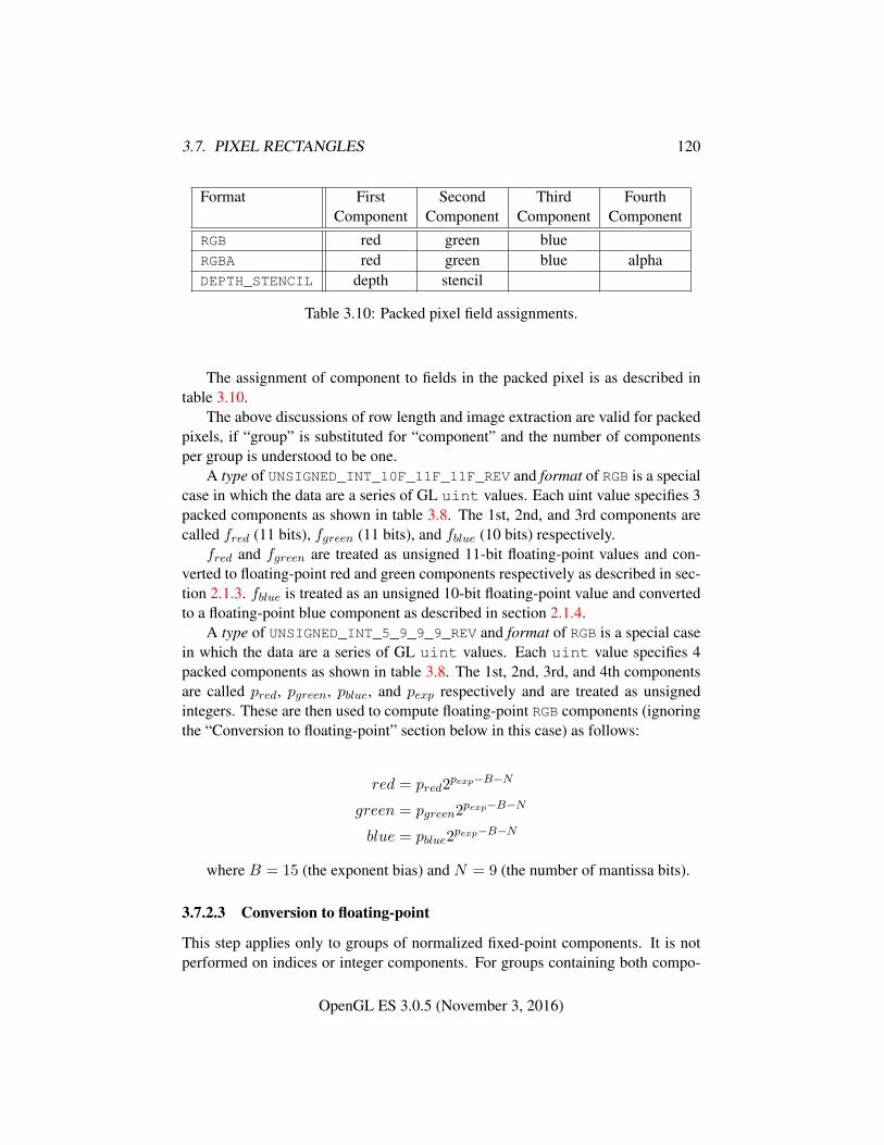
3.7. PIXEL RECTANGLES 120
Format First Second Third FourthComponent Component Component Component
RGB red green blueRGBA red green blue alphaDEPTH_STENCIL depth stencil
Table 3.10: Packed pixel field assignments.
The assignment of component to fields in the packed pixel is as described intable 3.10.
The above discussions of row length and image extraction are valid for packedpixels, if “group” is substituted for “component” and the number of componentsper group is understood to be one.
A type of UNSIGNED_INT_10F_11F_11F_REV and format of RGB is a specialcase in which the data are a series of GL uint values. Each uint value specifies 3packed components as shown in table 3.8. The 1st, 2nd, and 3rd components arecalled fred (11 bits), fgreen (11 bits), and fblue (10 bits) respectively.
fred and fgreen are treated as unsigned 11-bit floating-point values and con-verted to floating-point red and green components respectively as described in sec-tion 2.1.3. fblue is treated as an unsigned 10-bit floating-point value and convertedto a floating-point blue component as described in section 2.1.4.
A type of UNSIGNED_INT_5_9_9_9_REV and format of RGB is a special casein which the data are a series of GL uint values. Each uint value specifies 4packed components as shown in table 3.8. The 1st, 2nd, 3rd, and 4th componentsare called pred, pgreen, pblue, and pexp respectively and are treated as unsignedintegers. These are then used to compute floating-point RGB components (ignoringthe “Conversion to floating-point” section below in this case) as follows:
red = pred2pexp−B−N
green = pgreen2pexp−B−N
blue = pblue2pexp−B−N
where B = 15 (the exponent bias) and N = 9 (the number of mantissa bits).
3.7.2.3 Conversion to floating-point
This step applies only to groups of normalized fixed-point components. It is notperformed on indices or integer components. For groups containing both compo-
OpenGL ES 3.0.5 (November 3, 2016)
3.8. TEXTURING 121
nents and indices, such as DEPTH_STENCIL, the indices are not converted.Each element in a group is converted to a floating-point value. For unsigned
normalized fixed-point elements, equation 2.1 is used. For signed normalizedfixed-point elements, equation 2.2 is used.
3.7.2.4 Conversion to RGB
This step is applied only if the format is LUMINANCE or LUMINANCE_ALPHA. Ifthe format is LUMINANCE, then each group of one element is converted to a groupof R, G, and B (three) elements by copying the original single element into each ofthe three new elements. If the format is LUMINANCE_ALPHA, then each group oftwo elements is converted to a group of R, G, B, and A (four) elements by copyingthe first original element into each of the first three new elements and copying thesecond original element to the A (fourth) new element.
3.7.2.5 Final Expansion to RGBA
This step is performed only for non-depth component groups. Each group is con-verted to a group of 4 elements as follows: if a group does not contain an A ele-ment, then A is added and set to 1 for integer components or 1.0 for floating-pointcomponents. If any of R, G, or B is missing from the group, each missing elementis added and assigned a value of 0 for integer components or 0.0 for floating-pointcomponents.
3.8 Texturing
Texturing maps a portion of one or more specified images onto a fragment or ver-tex. This mapping is accomplished in shaders by sampling the color of an imageat the location indicated by specified (s, t, r) texture coordinates. Texture lookupsare typically used to modify a fragment’s RGBA color but may be used for anypurpose in a shader.
The internal data type of a texture may be signed or unsigned normalized fixed-point, signed or unsigned integer, or floating-point, depending on the internal for-mat of the texture. The correspondence between the internal format and the internaldata type is given in tables 3.13-3.14. Fixed-point and floating-point textures returna floating-point value and integer textures return signed or unsigned integer values.The fragment shader is responsible for interpreting the result of a texture lookup asthe correct data type, otherwise the result is undefined.
Each of the supported types of texture is a collection of images built fromtwo-or three-dimensional arrays of image elements referred to as texels. Two- and
OpenGL ES 3.0.5 (November 3, 2016)
3.8. TEXTURING 122
three-dimensional textures consist respectively of two-or three-dimensional texelarrays. Two-dimensional array textures are arrays of two-dimensional images,consisting of one or more layers. Cube maps are special two-dimensional arraytextures with six layers that represent the faces of a cube. When accessing a cubemap, the texture coordinates are projected onto one of the six faces of the cube.
Implementations must support texturing using multiple images. The followingsubsections (up to and including section 3.8.10) specify the GL operation with asingle texture. The process by which multiple texture images may be sampled andcombined by the application-supplied vertex and fragment shaders is described insections 2.12 and 3.9.
The coordinates used for texturing in a fragment shader are defined by theOpenGL ES Shading Language Specification.
The command
void ActiveTexture( enum texture );
specifies the active texture unit selector, ACTIVE_TEXTURE. Each texture imageunit consists of all the texture state defined in section 3.8.
The active texture unit selector selects the texture image unit accessed by com-mands involving texture image processing. Such commands include TexParame-ter, TexImage, BindTexture, and queries of all such state.
ActiveTexture generates the error INVALID_ENUM if an invalid texture is spec-ified. texture is a symbolic constant of the form TEXTUREi, indicating that textureunit i is to be modified. The constants obey TEXTUREi = TEXTURE0 + i (i is inthe range 0 to k− 1, where k is the value of MAX_COMBINED_TEXTURE_IMAGE_-UNITS).
The state required for the active texture image unit selector is a single integer.The initial value is TEXTURE0.
3.8.1 Texture Objects
Textures in GL are represented by named objects. The name space for textureobjects is the unsigned integers, with zero reserved by the GL to represent the de-fault texture object. The default texture object is bound to each of the TEXTURE_-2D, TEXTURE_3D, TEXTURE_2D_ARRAY, and TEXTURE_CUBE_MAP targets duringcontext initialization.
A new texture object is created by binding an unused name to one of thesetexture targets. The command
void GenTextures( sizei n, uint *textures );
OpenGL ES 3.0.5 (November 3, 2016)
3.8. TEXTURING 123
returns n previously unused texture names in textures. These names are marked asused, for the purposes of GenTextures only, but they do not acquire texture stateand a dimensionality until they are first bound, just as if they were unused. Thebinding is effected by calling
void BindTexture( enum target, uint texture );
with target set to the desired texture target and texture set to the unused name. Theresulting texture object is a new state vector, comprising all the state and with thesame initial values listed in section 3.8.14. The new texture object bound to targetis, and remains a texture of the dimensionality and type specified by target until itis deleted.
BindTexture may also be used to bind an existing texture object to any ofthese targets. The error INVALID_OPERATION is generated if an attempt is madeto bind a texture object of different dimensionality than the specified target. If thebind is successful no change is made to the state of the bound texture object, andany previous binding to target is broken.
While a texture object is bound, GL operations on the target to which it isbound affect the bound object, and queries of the target to which it is bound returnstate from the bound object. If texture mapping of the dimensionality of the targetto which a texture object is bound is enabled, the state of the bound texture objectdirects the texturing operation.
Texture objects are deleted by calling
void DeleteTextures( sizei n, const uint *textures );
textures contains n names of texture objects to be deleted. After a texture objectis deleted, it has no contents or dimensionality, and its name is again unused. Ifa texture that is currently bound to any of the target bindings of BindTexture isdeleted, it is as though BindTexture had been executed with the same target andtexture zero. Additionally, special care must be taken when deleting a texture if anyof the images of the texture are attached to a framebuffer object. See section 4.4.2.4for details.
Unused names in textures that have been marked as used for the purposes ofGenTextures are marked as unused again. Unused names in textures are silentlyignored, as is the name zero.
The texture object name space, including the initial two- and three- dimen-sional, two-dimensional array, and cube map texture objects, is shared among alltexture units. A texture object may be bound to more than one texture unit simul-taneously. After a texture object is bound, any GL operations on that target objectaffect any other texture units to which the same texture object is bound.
OpenGL ES 3.0.5 (November 3, 2016)
3.8. TEXTURING 124
Texture binding is affected by the setting of the state ACTIVE_TEXTURE. If atexture object is deleted, it as if all texture units which are bound to that textureobject are rebound to texture object zero.
3.8.2 Sampler Objects
The state necessary for texturing can be divided into two categories as describedin section 3.8.14. A GL texture object includes both categories. The first categoryrepresents dimensionality and other image parameters, and the second categoryrepresents sampling state. Additionally, a sampler object may be created to encap-sulate only the second category - the sampling state - of a texture object.
A new sampler object is created by binding an unused name to a texture unit.The command
void GenSamplers( sizei count, uint *samplers );
returns count previously unused sampler object names in samplers. The name zerois reserved by the GL to represent no sampler being bound to a texture unit. Thenames are marked as used, for the purposes of GenSamplers only, but they acquirestate only when they are first used as a parameter to BindSampler, SamplerPa-rameter*, GetSamplerParameter*, or IsSampler. When a sampler object is firstused in one of these functions, the resulting sampler object is initialized with anew state vector, comprising all the state and with the same initial values listed intable 6.10.
When a sampler object is bound to a texture unit, its state supersedes that of thetexture object(s) bound to that texture unit. If the sampler name zero is bound to atexture unit, the currently bound texture’s sampler state becomes active. A singlesampler object may be bound to multiple texture units simultaneously.
A sampler binding is effected by calling
void BindSampler( uint unit, uint sampler );
with unit set to the texture unit to which to bind the sampler and sampler set to thename of a sampler object returned from a previous call to GenSamplers.
If the bind is successful no change is made to the state of the bound samplerobject, and any previous binding to unit is broken.
BindSampler fails and an INVALID_OPERATION error is generated if sam-pler is not zero or a name returned from a previous call to GenSamplers, or ifsuch a name has since been deleted with DeleteSamplers. An INVALID_VALUE
error is generated if unit is greater than or equal to the value of MAX_COMBINED_-TEXTURE_IMAGE_UNITS.
OpenGL ES 3.0.5 (November 3, 2016)
3.8. TEXTURING 125
The currently bound sampler may be queried by calling GetIntegerv withpname set to SAMPLER_BINDING. When a sampler object is unbound from thetexture unit (by binding another sampler object, or the sampler object named zero,to that texture unit) the modified state is again replaced with the sampler state as-sociated with the texture object bound to that texture unit.
The parameters represented by a sampler object are a subset of those describedin section 3.8.7. Each parameter of a sampler object is set by calling
void SamplerParameter{if}( uint sampler, enum pname,T param );
void SamplerParameter{if}v( uint sampler, enum pname,const T *params );
sampler is the name of a sampler object previously reserved by a call to Gen-Samplers. pname is the name of a parameter to modify. In the first form of thecommand, param is a value to which to set a single-valued parameter; in the sec-ond form, params is an array of parameters whose type depends on the parameterbeing set.
An INVALID_OPERATION error is generated if sampler is not thename of a sampler object previously returned from a call to GenSam-plers. The values accepted in the pname parameter are TEXTURE_WRAP_-
S, TEXTURE_WRAP_T, TEXTURE_WRAP_R, TEXTURE_MIN_FILTER, TEXTURE_-MAG_FILTER, TEXTURE_MIN_LOD, TEXTURE_MAX_LOD, TEXTURE_COMPARE_-MODE, and TEXTURE_COMPARE_FUNC.
Data conversions are performed as specified in section 2.3.1.An INVALID_ENUM error is generated if pname is not the name of a parame-
ter accepted by SamplerParameter*. If the value of param is not an acceptablevalue for the parameter specified in pname, an error is generated as specified in thedescription of TexParameter*.
Modifying a parameter of a sampler object affects all texture units to whichthat sampler object is bound. Calling TexParameter has no effect on the samplerobject bound to the active texture unit. It will modify the parameters of the textureobject bound to that unit.
Sampler objects are deleted by calling
void DeleteSamplers( sizei count, const uint *samplers );
samplers contains count names of sampler objects to be deleted. After a samplerobject is deleted, its name is again unused. If a sampler object that is currentlybound to one or more texture units is deleted, it is as though BindSampler is called
OpenGL ES 3.0.5 (November 3, 2016)
3.8. TEXTURING 126
once for each texture unit to which the sampler is bound, with unit set to the textureunit and sampler set to zero. Unused names in samplers that have been marked asused for the purposes of GenSamplers are marked as unused again. Unused namesin samplers are silently ignored, as is the reserved name zero.
3.8.3 Texture Image Specification
The command
void TexImage3D( enum target, int level, int internalformat,sizei width, sizei height, sizei depth, int border,enum format, enum type, const void *data );
is used to specify a three-dimensional texture image. target must be one ofTEXTURE_3D for a three-dimensional texture or TEXTURE_2D_ARRAY for an two-dimensional array texture. format, type, and data specify the format of the imagedata, the type of those data, and a reference to the image data in the currently boundpixel unpack buffer or client memory, as described in section 3.7.2.
The groups in memory are treated as being arranged in a sequence of adjacentrectangles. Each rectangle is a two-dimensional image, whose size and organiza-tion are specified by the width and height parameters to TexImage3D. The val-ues of UNPACK_ROW_LENGTH and UNPACK_ALIGNMENT control the row-to-rowspacing in these images as described in section 3.7.2. If the value of the integerparameter UNPACK_IMAGE_HEIGHT is zero, then the number of rows in each two-dimensional image is height; otherwise the number of rows is UNPACK_IMAGE_-HEIGHT. Each two-dimensional image comprises an integral number of rows, andis exactly adjacent to its neighbor images.
The mechanism for selecting a sub-volume of a three-dimensional image relieson the integer parameter UNPACK_SKIP_IMAGES. If UNPACK_SKIP_IMAGES ispositive, the pointer is advanced by UNPACK_SKIP_IMAGES times the number ofelements in one two-dimensional image before obtaining the first group from mem-ory. Then depth two-dimensional images are processed, each having a subimageextracted as described in section 3.7.2.
The selected groups are transferred to the GL as described in section 3.7.2 andthen clamped to the representable range of the internal format. If the internal-format of the texture is signed or unsigned integer, components are clamped to[−2n−1, 2n−1 − 1] or [0, 2n − 1], respectively, where n is the number of bits percomponent. For color component groups, if the internalformat of the texture issigned or unsigned normalized fixed-point, components are clamped to [−1, 1] or[0, 1], respectively. For depth component groups, the depth value is clamped to[0, 1]. Otherwise, values are not modified.
OpenGL ES 3.0.5 (November 3, 2016)
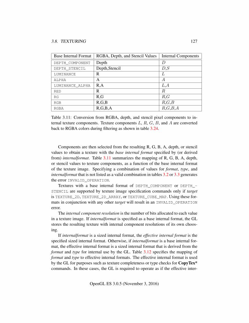
3.8. TEXTURING 127
Base Internal Format RGBA, Depth, and Stencil Values Internal ComponentsDEPTH_COMPONENT Depth D
DEPTH_STENCIL Depth,Stencil D,SLUMINANCE R L
ALPHA A A
LUMINANCE_ALPHA R,A L,ARED R R
RG R,G R,GRGB R,G,B R,G,BRGBA R,G,B,A R,G,B,A
Table 3.11: Conversion from RGBA, depth, and stencil pixel components to in-ternal texture components. Texture components L, R, G, B, and A are convertedback to RGBA colors during filtering as shown in table 3.24.
Components are then selected from the resulting R, G, B, A, depth, or stencilvalues to obtain a texture with the base internal format specified by (or derivedfrom) internalformat. Table 3.11 summarizes the mapping of R, G, B, A, depth,or stencil values to texture components, as a function of the base internal formatof the texture image. Specifying a combination of values for format, type, andinternalformat that is not listed as a valid combination in tables 3.2 or 3.3 generatesthe error INVALID_OPERATION.
Textures with a base internal format of DEPTH_COMPONENT or DEPTH_-
STENCIL are supported by texture image specification commands only if targetis TEXTURE_2D, TEXTURE_2D_ARRAY, or TEXTURE_CUBE_MAP. Using these for-mats in conjunction with any other target will result in an INVALID_OPERATION
error.The internal component resolution is the number of bits allocated to each value
in a texture image. If internalformat is specified as a base internal format, the GLstores the resulting texture with internal component resolutions of its own choos-ing.
If internalformat is a sized internal format, the effective internal format is thespecified sized internal format. Otherwise, if internalformat is a base internal for-mat, the effective internal format is a sized internal format that is derived from theformat and type for internal use by the GL. Table 3.12 specifies the mapping offormat and type to effective internal formats. The effective internal format is usedby the GL for purposes such as texture completeness or type checks for CopyTex*commands. In these cases, the GL is required to operate as if the effective inter-
OpenGL ES 3.0.5 (November 3, 2016)
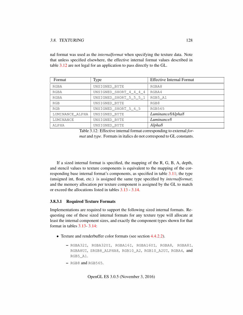
3.8. TEXTURING 128
nal format was used as the internalformat when specifying the texture data. Notethat unless specified elsewhere, the effective internal format values described intable 3.12 are not legal for an application to pass directly to the GL.
Format Type Effective Internal FormatRGBA UNSIGNED_BYTE RGBA8
RGBA UNSIGNED_SHORT_4_4_4_4 RGBA4
RGBA UNSIGNED_SHORT_5_5_5_1 RGB5_A1
RGB UNSIGNED_BYTE RGB8
RGB UNSIGNED_SHORT_5_6_5 RGB565
LUMINANCE_ALPHA UNSIGNED_BYTE Luminance8Alpha8LUMINANCE UNSIGNED_BYTE Luminance8ALPHA UNSIGNED_BYTE Alpha8
Table 3.12: Effective internal format corresponding to external for-mat and type. Formats in italics do not correspond to GL constants.
If a sized internal format is specified, the mapping of the R, G, B, A, depth,and stencil values to texture components is equivalent to the mapping of the cor-responding base internal format’s components, as specified in table 3.11; the type(unsigned int, float, etc.) is assigned the same type specified by internalformat;and the memory allocation per texture component is assigned by the GL to matchor exceed the allocations listed in tables 3.13 - 3.14.
3.8.3.1 Required Texture Formats
Implementations are required to support the following sized internal formats. Re-questing one of these sized internal formats for any texture type will allocate atleast the internal component sizes, and exactly the component types shown for thatformat in tables 3.13- 3.14:
• Texture and renderbuffer color formats (see section 4.4.2.2).
– RGBA32I, RGBA32UI, RGBA16I, RGBA16UI, RGBA8, RGBA8I,RGBA8UI, SRGB8_ALPHA8, RGB10_A2, RGB10_A2UI, RGBA4, andRGB5_A1.
– RGB8 and RGB565.
OpenGL ES 3.0.5 (November 3, 2016)
3.8. TEXTURING 129
– RG32I, RG32UI, RG16I, RG16UI, RG8, RG8I, and RG8UI.
– R32I, R32UI, R16I, R16UI, R8, R8I, and R8UI.
• Texture-only color formats:
– RGBA32F, RGBA16F, and RGBA8_SNORM.
– RGB32F, RGB32I, and RGB32UI.
– RGB16F, RGB16I, and RGB16UI.
– RGB8_SNORM, RGB8I, RGB8UI, and SRGB8.
– R11F_G11F_B10F and RGB9_E5.
– RG32F, RG16F, and RG8_SNORM.
– R32F, R16F, and R8_SNORM.
• Depth formats: DEPTH_COMPONENT32F, DEPTH_COMPONENT24, andDEPTH_COMPONENT16.
• Combined depth+stencil formats: DEPTH32F_STENCIL8 and DEPTH24_-
STENCIL8.
3.8.3.2 Encoding of Special Internal Formats
If internalformat is R11F_G11F_B10F, the red, green, and blue bits are convertedto unsigned 11-bit, unsigned 11-bit, and unsigned 10-bit floating-point values asdescribed in sections 2.1.3 and 2.1.4.
If internalformat is RGB9_E5, the red, green, and blue bits are converted to ashared exponent format according to the following procedure:
Components red, green, and blue are first clamped (in the process, mappingNaN to zero) as follows:
redc = max(0,min(sharedexpmax, red))
greenc = max(0,min(sharedexpmax, green))
bluec = max(0,min(sharedexpmax, blue))
where
sharedexpmax =(2N − 1)
2N2Emax−B.
N is the number of mantissa bits per component (9), B is the exponent bias (15),and Emax is the maximum allowed biased exponent value (31).
The largest clamped component, maxc, is determined:
OpenGL ES 3.0.5 (November 3, 2016)
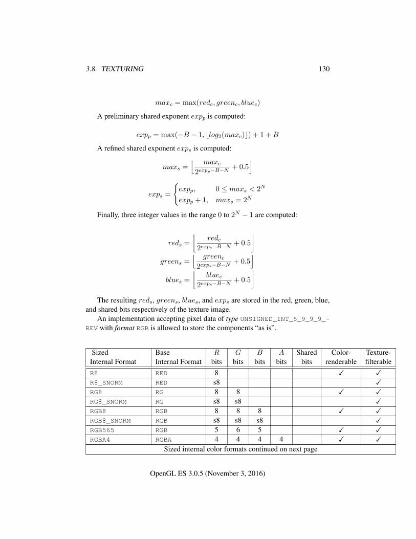
3.8. TEXTURING 130
maxc = max(redc, greenc, bluec)
A preliminary shared exponent expp is computed:
expp = max(−B − 1, blog2(maxc)c) + 1 +B
A refined shared exponent exps is computed:
maxs =⌊ maxc
2expp−B−N+ 0.5
⌋
exps =
{expp, 0 ≤ maxs < 2N
expp + 1, maxs = 2N
Finally, three integer values in the range 0 to 2N − 1 are computed:
reds =
⌊redc
2exps−B−N+ 0.5
⌋greens =
⌊ greenc2exps−B−N
+ 0.5⌋
blues =
⌊bluec
2exps−B−N+ 0.5
⌋The resulting reds, greens, blues, and exps are stored in the red, green, blue,
and shared bits respectively of the texture image.An implementation accepting pixel data of type UNSIGNED_INT_5_9_9_9_-
REV with format RGB is allowed to store the components “as is”.
Sized Base R G B A Shared Color- Texture-Internal Format Internal Format bits bits bits bits bits renderable filterableR8 RED 8 � �R8_SNORM RED s8 �RG8 RG 8 8 � �RG8_SNORM RG s8 s8 �RGB8 RGB 8 8 8 � �RGB8_SNORM RGB s8 s8 s8 �RGB565 RGB 5 6 5 � �RGBA4 RGBA 4 4 4 4 � �
Sized internal color formats continued on next page
OpenGL ES 3.0.5 (November 3, 2016)
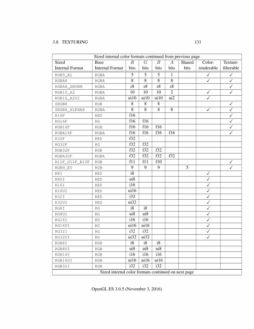
3.8. TEXTURING 131
Sized internal color formats continued from previous pageSized Base R G B A Shared Color- Texture-Internal Format Internal Format bits bits bits bits bits renderable filterableRGB5_A1 RGBA 5 5 5 1 � �RGBA8 RGBA 8 8 8 8 � �RGBA8_SNORM RGBA s8 s8 s8 s8 �RGB10_A2 RGBA 10 10 10 2 � �RGB10_A2UI RGBA ui10 ui10 ui10 ui2 �SRGB8 RGB 8 8 8 �SRGB8_ALPHA8 RGBA 8 8 8 8 � �R16F RED f16 �RG16F RG f16 f16 �RGB16F RGB f16 f16 f16 �RGBA16F RGBA f16 f16 f16 f16 �R32F RED f32RG32F RG f32 f32RGB32F RGB f32 f32 f32RGBA32F RGBA f32 f32 f32 f32R11F_G11F_B10F RGB f11 f11 f10 �RGB9_E5 RGB 9 9 9 5 �R8I RED i8 �R8UI RED ui8 �R16I RED i16 �R16UI RED ui16 �R32I RED i32 �R32UI RED ui32 �RG8I RG i8 i8 �RG8UI RG ui8 ui8 �RG16I RG i16 i16 �RG16UI RG ui16 ui16 �RG32I RG i32 i32 �RG32UI RG ui32 ui32 �RGB8I RGB i8 i8 i8RGB8UI RGB ui8 ui8 ui8RGB16I RGB i16 i16 i16RGB16UI RGB ui16 ui16 ui16RGB32I RGB i32 i32 i32
Sized internal color formats continued on next page
OpenGL ES 3.0.5 (November 3, 2016)
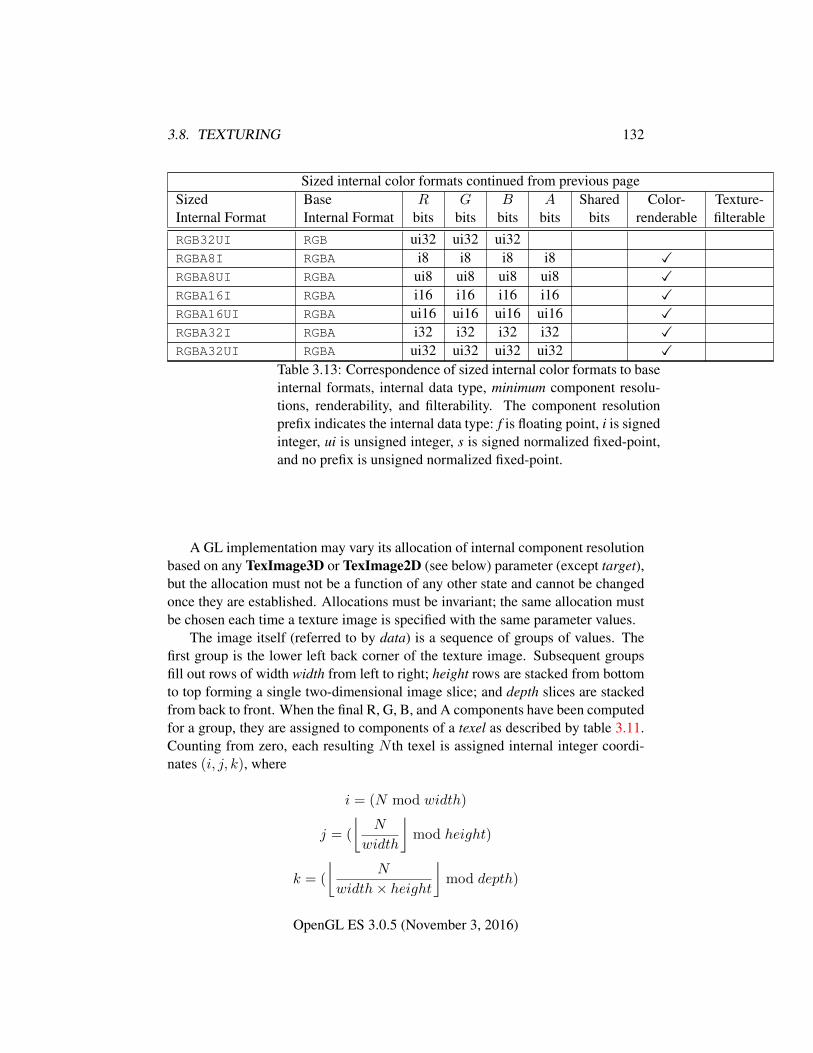
3.8. TEXTURING 132
Sized internal color formats continued from previous pageSized Base R G B A Shared Color- Texture-Internal Format Internal Format bits bits bits bits bits renderable filterableRGB32UI RGB ui32 ui32 ui32RGBA8I RGBA i8 i8 i8 i8 �RGBA8UI RGBA ui8 ui8 ui8 ui8 �RGBA16I RGBA i16 i16 i16 i16 �RGBA16UI RGBA ui16 ui16 ui16 ui16 �RGBA32I RGBA i32 i32 i32 i32 �RGBA32UI RGBA ui32 ui32 ui32 ui32 �
Table 3.13: Correspondence of sized internal color formats to baseinternal formats, internal data type, minimum component resolu-tions, renderability, and filterability. The component resolutionprefix indicates the internal data type: f is floating point, i is signedinteger, ui is unsigned integer, s is signed normalized fixed-point,and no prefix is unsigned normalized fixed-point.
A GL implementation may vary its allocation of internal component resolutionbased on any TexImage3D or TexImage2D (see below) parameter (except target),but the allocation must not be a function of any other state and cannot be changedonce they are established. Allocations must be invariant; the same allocation mustbe chosen each time a texture image is specified with the same parameter values.
The image itself (referred to by data) is a sequence of groups of values. Thefirst group is the lower left back corner of the texture image. Subsequent groupsfill out rows of width width from left to right; height rows are stacked from bottomto top forming a single two-dimensional image slice; and depth slices are stackedfrom back to front. When the final R, G, B, and A components have been computedfor a group, they are assigned to components of a texel as described by table 3.11.Counting from zero, each resulting N th texel is assigned internal integer coordi-nates (i, j, k), where
i = (N mod width)
j = (
⌊N
width
⌋mod height)
k = (
⌊N
width× height
⌋mod depth)
OpenGL ES 3.0.5 (November 3, 2016)
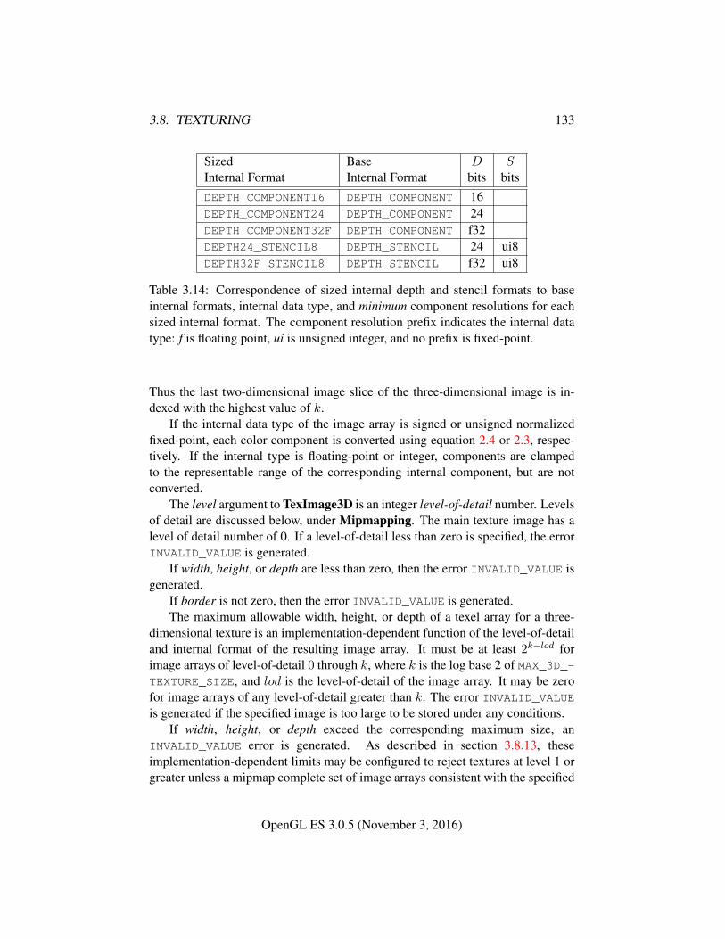
3.8. TEXTURING 133
Sized Base D SInternal Format Internal Format bits bitsDEPTH_COMPONENT16 DEPTH_COMPONENT 16DEPTH_COMPONENT24 DEPTH_COMPONENT 24DEPTH_COMPONENT32F DEPTH_COMPONENT f32DEPTH24_STENCIL8 DEPTH_STENCIL 24 ui8DEPTH32F_STENCIL8 DEPTH_STENCIL f32 ui8
Table 3.14: Correspondence of sized internal depth and stencil formats to baseinternal formats, internal data type, and minimum component resolutions for eachsized internal format. The component resolution prefix indicates the internal datatype: f is floating point, ui is unsigned integer, and no prefix is fixed-point.
Thus the last two-dimensional image slice of the three-dimensional image is in-dexed with the highest value of k.
If the internal data type of the image array is signed or unsigned normalizedfixed-point, each color component is converted using equation 2.4 or 2.3, respec-tively. If the internal type is floating-point or integer, components are clampedto the representable range of the corresponding internal component, but are notconverted.
The level argument to TexImage3D is an integer level-of-detail number. Levelsof detail are discussed below, under Mipmapping. The main texture image has alevel of detail number of 0. If a level-of-detail less than zero is specified, the errorINVALID_VALUE is generated.
If width, height, or depth are less than zero, then the error INVALID_VALUE isgenerated.
If border is not zero, then the error INVALID_VALUE is generated.The maximum allowable width, height, or depth of a texel array for a three-
dimensional texture is an implementation-dependent function of the level-of-detailand internal format of the resulting image array. It must be at least 2k−lod forimage arrays of level-of-detail 0 through k, where k is the log base 2 of MAX_3D_-TEXTURE_SIZE, and lod is the level-of-detail of the image array. It may be zerofor image arrays of any level-of-detail greater than k. The error INVALID_VALUEis generated if the specified image is too large to be stored under any conditions.
If width, height, or depth exceed the corresponding maximum size, anINVALID_VALUE error is generated. As described in section 3.8.13, theseimplementation-dependent limits may be configured to reject textures at level 1 orgreater unless a mipmap complete set of image arrays consistent with the specified
OpenGL ES 3.0.5 (November 3, 2016)
3.8. TEXTURING 134
sizes can be supported.If a pixel unpack buffer object is bound and storing texture data would access
memory beyond the end of the pixel unpack buffer, an INVALID_OPERATION errorresults.
In a similar fashion, the maximum allowable width of a texel array for a two-dimensional texture, or two-dimensional array texture, and the maximum allowableheight of a two-dimensional texture or two-dimensional array texture, must be atleast 2k−lod for image arrays of level 0 through k, where k is the log base 2 ofMAX_TEXTURE_SIZE. The maximum allowable width and height of a cube maptexture must be the same, and must be at least 2k−lod for image arrays level 0through k, where k is the log base 2 of MAX_CUBE_MAP_TEXTURE_SIZE. Themaximum number of layers for two-dimensional array textures (depth) must be atleast MAX_ARRAY_TEXTURE_LAYERS for all levels.
The command
void TexImage2D( enum target, int level, int internalformat,sizei width, sizei height, int border, enum format,enum type, const void *data );
is used to specify a two-dimensional texture image. target must be one ofTEXTURE_2D for a two-dimensional texture, or one of TEXTURE_CUBE_MAP_-POSITIVE_X, TEXTURE_CUBE_MAP_NEGATIVE_X, TEXTURE_CUBE_MAP_-
POSITIVE_Y, TEXTURE_CUBE_MAP_NEGATIVE_Y, TEXTURE_CUBE_MAP_-
POSITIVE_Z, or TEXTURE_CUBE_MAP_NEGATIVE_Z for a cube map texture.The other parameters match the corresponding parameters of TexImage3D.
For the purposes of decoding the texture image, TexImage2D is equivalent tocalling TexImage3D with corresponding arguments and depth of 1, except thatUNPACK_SKIP_IMAGES is ignored.
A two-dimensional texture consists of a single two-dimensional texture image.A cube map texture is a set of six two-dimensional texture images. The six cubemap texture targets form a single cube map texture though each target names adistinct face of the cube map. The TEXTURE_CUBE_MAP_* targets listed aboveupdate their appropriate cube map face 2D texture image. Note that the six cubemap two-dimensional image tokens such as TEXTURE_CUBE_MAP_POSITIVE_Xare used when specifying, updating, or querying one of a cube map’s six two-dimensional images, but when binding to a cube map texture object (that is whenthe cube map is accessed as a whole as opposed to a particular two-dimensionalimage), the TEXTURE_CUBE_MAP target is specified.
When the target parameter to TexImage2D is one of the six cube map two-dimensional image targets, the error INVALID_VALUE is generated if the widthand height parameters are not equal.
OpenGL ES 3.0.5 (November 3, 2016)
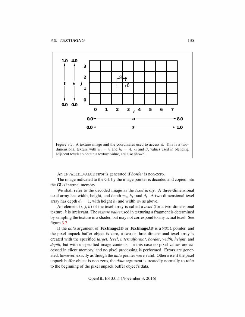
3.8. TEXTURING 135
Figure 3.7. A texture image and the coordinates used to access it. This is a two-dimensional texture with wt = 8 and ht = 4. α and β, values used in blendingadjacent texels to obtain a texture value, are also shown.
An INVALID_VALUE error is generated if border is non-zero.The image indicated to the GL by the image pointer is decoded and copied into
the GL’s internal memory.We shall refer to the decoded image as the texel array. A three-dimensional
texel array has width, height, and depth wt, ht, and dt. A two-dimensional texelarray has depth dt = 1, with height ht and width wt as above.
An element (i, j, k) of the texel array is called a texel (for a two-dimensionaltexture, k is irrelevant. The texture value used in texturing a fragment is determinedby sampling the texture in a shader, but may not correspond to any actual texel. Seefigure 3.7.
If the data argument of TexImage2D or TexImage3D is a NULL pointer, andthe pixel unpack buffer object is zero, a two-or three-dimensional texel array iscreated with the specified target, level, internalformat, border, width, height, anddepth, but with unspecified image contents. In this case no pixel values are ac-cessed in client memory, and no pixel processing is performed. Errors are gener-ated, however, exactly as though the data pointer were valid. Otherwise if the pixelunpack buffer object is non-zero, the data argument is treatedly normally to referto the beginning of the pixel unpack buffer object’s data.
OpenGL ES 3.0.5 (November 3, 2016)
3.8. TEXTURING 136
3.8.4 Immutable-Format Texture Images
An alternative set of commands is provided for specifying the properties of alllevels of a texture at once. Once a texture is specified with such a command,the format and dimensions of all levels become immutable. The contents of theimages and the parameters can still be modified. Such a texture is referred to as animmutable-format texture. The immutability status of a texture can be determinedby calling GetTexParameter with pname TEXTURE_IMMUTABLE_FORMAT.
Each of the commands below is described by pseudo-code which indicates theeffect on the dimensions and format of the texture. For all of the commands, thefollowing apply in addition to the pseudo-code:
• If the default texture object is bound to target, an INVALID_OPERATION
error is generated.
• If executing the pseudo-code results in an OUT_OF_MEMORY error, the erroris generated and the results of executing the command are undefined.
• If executing the pseudo-code would result in any other error, the error isgenerated and the command will have no effect.
• Any existing levels that are not replaced are reset to their initial state.
• If width, height, depth or levels is less than 1, the error INVALID_VALUE isgenerated.
• The pixel unpack buffer should be considered to be zero; i.e., the imagecontents are unspecified.
• Since no pixel data are provided, the format and type values used in thepseudo-code are irrelevant; they can be considered to be any values that arelegal to use with internalformat.
• If the command is successful, TEXTURE_IMMUTABLE_FORMAT becomesTRUE and TEXTURE_IMMUTABLE_LEVELS becomes levels.
• If internalformat is a compressed texture format, then references to TexIm-age* should be replaced by CompressedTexImage*, with format, type anddata replaced by any valid imageSize and data. If there is no imageSize forwhich this command would have been valid, an INVALID_OPERATION erroris generated.
• If internalformat is one of the unsized base internal formats listed in ta-ble 3.3, an INVALID_ENUM error is generated.
OpenGL ES 3.0.5 (November 3, 2016)
3.8. TEXTURING 137
The command
void TexStorage2D( enum target, sizei levels,enum internalformat, sizei width, sizei height );
specifies all the levels of a two-dimensional or cube-map texture at the same time.The pseudo-code depends on the target:
TEXTURE_2D:
for (i = 0; i < levels; i++) {TexImage2D(target, i, internalformat, width, height, 0,
format, type, NULL);width = max(1,
⌊width
2
⌋);
height = max(1,⌊height
2
⌋);
}
TEXTURE_CUBE_MAP:
for (i = 0; i < levels; i++) {for face in (+X, -X, +Y, -Y, +Z, -Z) {
TexImage2D(face, i, internalformat, width, height, 0,format, type, NULL);
}width = max(1,
⌊width
2
⌋);
height = max(1,⌊height
2
⌋);
}
If target is not one of those listed above, an INVALID_ENUM error is generated.An INVALID_OPERATION error is generated if levels is greater than
blog2(max(width, height))c+ 1.The command
void TexStorage3D( enum target, sizei levels,enum internalformat, sizei width, sizei height,sizei depth );
specifies all the levels of a three-dimensional texture or two-dimensional array tex-ture. The pseudocode depends on target:TEXTURE_3D:
OpenGL ES 3.0.5 (November 3, 2016)
3.8. TEXTURING 138
for (i = 0; i < levels; i++) {TexImage3D(target, i, internalformat, width, height, depth, 0,
format, type, NULL);width = max(1,
⌊width
2
⌋);
height = max(1,⌊height
2
⌋);
depth = max(1,⌊depth
2
⌋);
}
TEXTURE_2D_ARRAY:
for (i = 0; i < levels; i++) {TexImage3D(target, i, internalformat, width, height, depth, 0,
format, type, NULL);width = max(1,
⌊width
2
⌋);
height = max(1,⌊height
2
⌋);
}
If target is not one of those listed above, an INVALID_ENUM error is generated.An INVALID_OPERATION error is generated if any of the following conditions
hold:
• target is TEXTURE_3D and levels is greater thanblog2(max(width, height, depth)))c+ 1
• target is TEXTURE_2D_ARRAY and levels is greater thanblog2(max(width, height))c+ 1
After a successful call to any TexStorage* command, no further changes tothe dimensions or format of the texture object may be made. Other commandsmay only alter the texel values and texture parameters. Using any of the followingcommands with the same texture will result in an INVALID_OPERATION errorbeing generated, even if it does not affect the dimensions or format:
• TexImage*
• CompressedTexImage*
• CopyTexImage*
• TexStorage*
OpenGL ES 3.0.5 (November 3, 2016)
3.8. TEXTURING 139
3.8.5 Alternate Texture Image Specification Commands
Two-dimensional texture images may also be specified using image data taken di-rectly from the framebuffer, and rectangular subregions of existing texture imagesmay be respecified.
The command
void CopyTexImage2D( enum target, int level,enum internalformat, int x, int y, sizei width,sizei height, int border );
defines a two-dimensional texel array in exactly the manner of Tex-Image2D, except that the image data are taken from the framebufferrather than from client memory. target must be one of TEXTURE_-
2D, TEXTURE_CUBE_MAP_POSITIVE_X, TEXTURE_CUBE_MAP_NEGATIVE_X,TEXTURE_CUBE_MAP_POSITIVE_Y, TEXTURE_CUBE_MAP_NEGATIVE_-
Y, TEXTURE_CUBE_MAP_POSITIVE_Z, or TEXTURE_CUBE_MAP_NEGATIVE_Z.x, y, width, and height correspond precisely to the corresponding arguments toReadPixels (refer to section 4.3.2); they specify the image’s width and height, andthe lower left (x, y) coordinates of the framebuffer region to be copied. The imageis taken from the current color buffer exactly as if these arguments were passed toReadPixels with arguments format and type set according to table 3.15, stoppingafter conversion of RGBA values. The error INVALID_OPERATION is generatedif floating-point RGBA data is required; if signed integer RGBA data is requiredand the format of the current color buffer is not signed integer; if unsigned integerRGBA data is required and the format of the current color buffer is not unsignedinteger; or if fixed-point RGBA data is required and the format of the current colorbuffer is not fixed-point. The error INVALID_OPERATION is also generated if thevalue of FRAMEBUFFER_ATTACHMENT_COLOR_ENCODING for the framebuffer at-tachment corresponding to the read buffer is LINEAR (see section 6.1.13) and in-ternalformat is one of the sRGB formats described in section 3.8.16, or if the valueof FRAMEBUFFER_ATTACHMENT_COLOR_ENCODING is SRGB and internalformatis not one of the sRGB formats.
Subsequent processing is identical to that described for TexImage2D, begin-ning with clamping of the R, G, B, and A values from the resulting pixel groups.Parameters level, internalformat, and border are specified using the same values,with the same meanings, as the equivalent arguments of TexImage2D. internalfor-mat is further constrained such that color buffer components can be dropped duringthe conversion to internalformat, but new components cannot be added. For exam-ple, an RGB color buffer can be used to create LUMINANCE or RGB textures, but notALPHA, LUMINANCE_ALPHA, or RGBA textures. Table 3.16 summarizes the valid
OpenGL ES 3.0.5 (November 3, 2016)
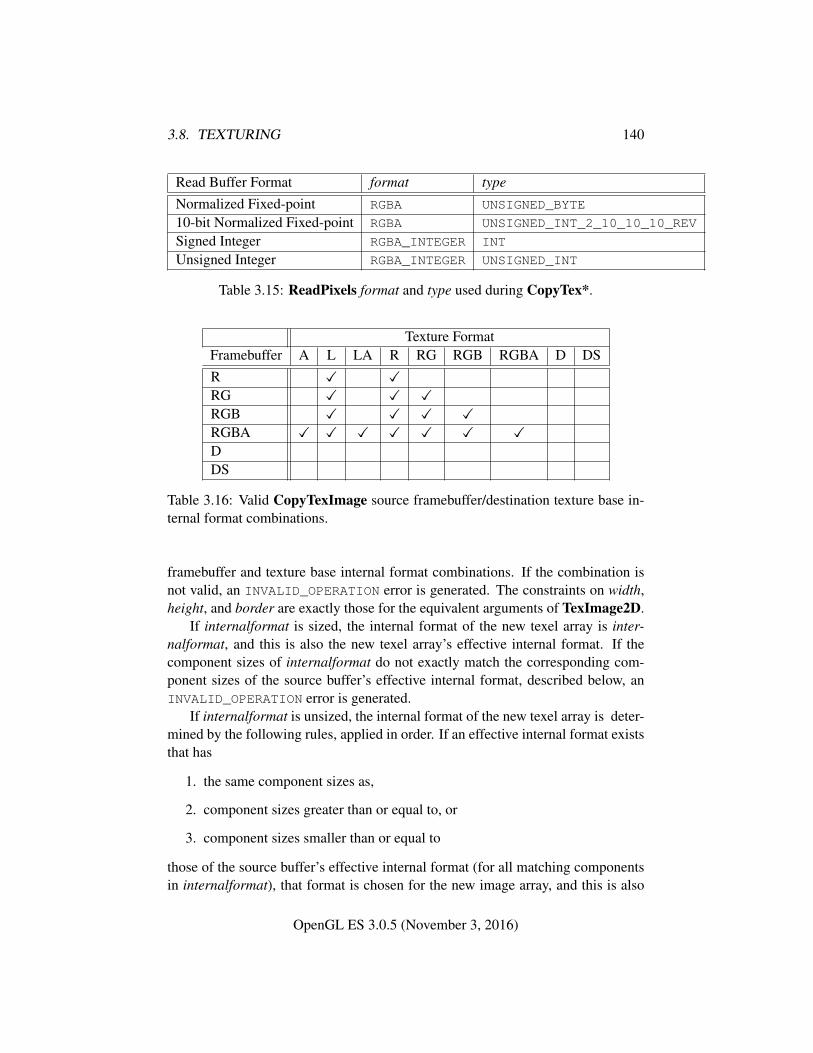
3.8. TEXTURING 140
Read Buffer Format format type
Normalized Fixed-point RGBA UNSIGNED_BYTE
10-bit Normalized Fixed-point RGBA UNSIGNED_INT_2_10_10_10_REV
Signed Integer RGBA_INTEGER INT
Unsigned Integer RGBA_INTEGER UNSIGNED_INT
Table 3.15: ReadPixels format and type used during CopyTex*.
Texture FormatFramebuffer A L LA R RG RGB RGBA D DSR � �RG � � �RGB � � � �RGBA � � � � � � �DDS
Table 3.16: Valid CopyTexImage source framebuffer/destination texture base in-ternal format combinations.
framebuffer and texture base internal format combinations. If the combination isnot valid, an INVALID_OPERATION error is generated. The constraints on width,height, and border are exactly those for the equivalent arguments of TexImage2D.
If internalformat is sized, the internal format of the new texel array is inter-nalformat, and this is also the new texel array’s effective internal format. If thecomponent sizes of internalformat do not exactly match the corresponding com-ponent sizes of the source buffer’s effective internal format, described below, anINVALID_OPERATION error is generated.
If internalformat is unsized, the internal format of the new texel array is deter-mined by the following rules, applied in order. If an effective internal format existsthat has
1. the same component sizes as,
2. component sizes greater than or equal to, or
3. component sizes smaller than or equal to
those of the source buffer’s effective internal format (for all matching componentsin internalformat), that format is chosen for the new image array, and this is also
OpenGL ES 3.0.5 (November 3, 2016)
3.8. TEXTURING 141
the new texel array’s effective internal format. When matching formats that involvea luminance component, a luminance component is considered to match with a redcomponent. If multiple possible matches exist in the same rule, the one with theclosest component sizes is chosen. Note that the above rules disallow matcheswhere some components sizes are smaller and others are larger (such as RGB10_-A2).
The effective internal format of the source buffer is determined with the fol-lowing rules applied in order:
• If the source buffer is a texture or renderbuffer that was created with a sizedinternal format then the effective internal format is the source buffer’s sizedinternal format.
• If the source buffer is a texture that was created with an unsized base internalformat, then the effective internal format is the source image array’s effectiveinternal format, as specified by table 3.12, which is determined from theformat and type that were used when the source image array was specifiedby TexImage*.
• Otherwise the effective internal format is determined by the row in ta-ble 3.17 or table 3.18 where Destination Internal Format matches inter-nalformat and where the Source Red Size, Source Green Size, SourceBlue Size, and Source Alpha Size are consistent with the values ofthe source buffer’s FRAMEBUFFER_RED_SIZE, FRAMEBUFFER_GREEN_-SIZE, FRAMEBUFFER_BLUE_SIZE, and FRAMEBUFFER_ALPHA_SIZE, re-spectively. Table 3.17 is used if the FRAMEBUFFER_ATTACHMENT_-
ENCODING is LINEAR and table 3.18 is used if the FRAMEBUFFER_-
ATTACHMENT_ENCODING is SRGB. ”any sized” matches any specified sizedinternal format. ”N/A” means the source buffer’s component size is ignored.If there are no rows in the appropriate table, 3.17 or 3.18, that match the in-ternalformat and source buffer component sizes, then the source buffer doesnot have an effective internal format, and an INVALID_OPERATION error isgenerated.
When the target parameter to CopyTexImage2D is one of the six cube maptwo-dimensional image targets, the error INVALID_VALUE is generated if the widthand height parameters are not equal.
Four additional commands,
void TexSubImage3D( enum target, int level, int xoffset,int yoffset, int zoffset, sizei width, sizei height,
OpenGL ES 3.0.5 (November 3, 2016)
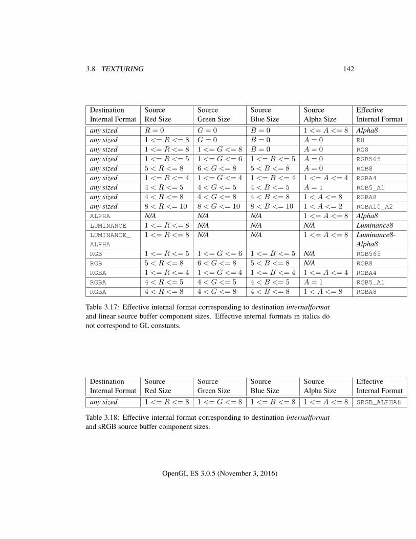
3.8. TEXTURING 142
Destination Source Source Source Source EffectiveInternal Format Red Size Green Size Blue Size Alpha Size Internal Formatany sized R = 0 G = 0 B = 0 1 <= A <= 8 Alpha8any sized 1 <= R <= 8 G = 0 B = 0 A = 0 R8
any sized 1 <= R <= 8 1 <= G <= 8 B = 0 A = 0 RG8
any sized 1 <= R <= 5 1 <= G <= 6 1 <= B <= 5 A = 0 RGB565
any sized 5 < R <= 8 6 < G <= 8 5 < B <= 8 A = 0 RGB8
any sized 1 <= R <= 4 1 <= G <= 4 1 <= B <= 4 1 <= A <= 4 RGBA4
any sized 4 < R <= 5 4 < G <= 5 4 < B <= 5 A = 1 RGB5_A1
any sized 4 < R <= 8 4 < G <= 8 4 < B <= 8 1 < A <= 8 RGBA8
any sized 8 < R <= 10 8 < G <= 10 8 < B <= 10 1 < A <= 2 RGBA10_A2
ALPHA N/A N/A N/A 1 <= A <= 8 Alpha8LUMINANCE 1 <= R <= 8 N/A N/A N/A Luminance8LUMINANCE_ 1 <= R <= 8 N/A N/A 1 <= A <= 8 Luminance8-ALPHA Alpha8RGB 1 <= R <= 5 1 <= G <= 6 1 <= B <= 5 N/A RGB565
RGB 5 < R <= 8 6 < G <= 8 5 < B <= 8 N/A RGB8
RGBA 1 <= R <= 4 1 <= G <= 4 1 <= B <= 4 1 <= A <= 4 RGBA4
RGBA 4 < R <= 5 4 < G <= 5 4 < B <= 5 A = 1 RGB5_A1
RGBA 4 < R <= 8 4 < G <= 8 4 < B <= 8 1 < A <= 8 RGBA8
Table 3.17: Effective internal format corresponding to destination internalformatand linear source buffer component sizes. Effective internal formats in italics donot correspond to GL constants.
Destination Source Source Source Source EffectiveInternal Format Red Size Green Size Blue Size Alpha Size Internal Formatany sized 1 <= R <= 8 1 <= G <= 8 1 <= B <= 8 1 <= A <= 8 SRGB_ALPHA8
Table 3.18: Effective internal format corresponding to destination internalformatand sRGB source buffer component sizes.
OpenGL ES 3.0.5 (November 3, 2016)
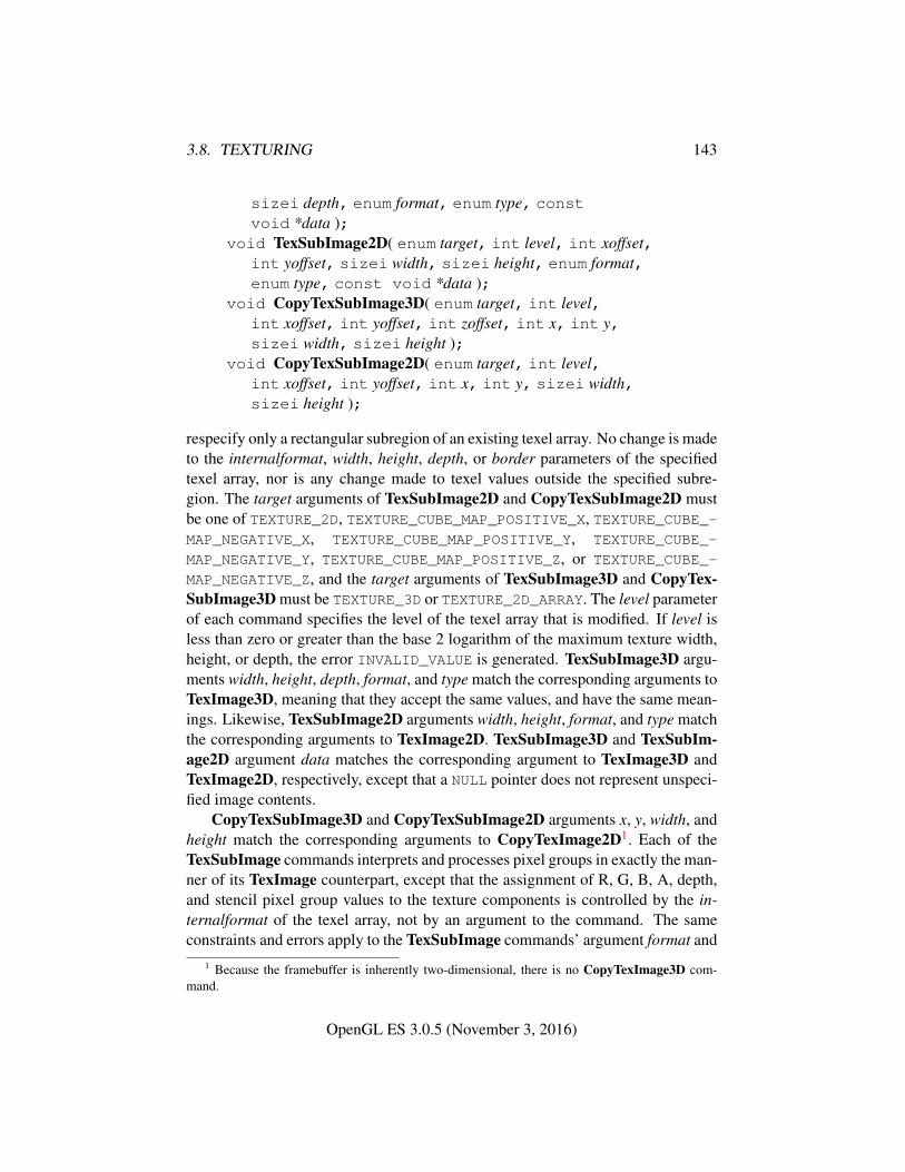
3.8. TEXTURING 143
sizei depth, enum format, enum type, constvoid *data );
void TexSubImage2D( enum target, int level, int xoffset,int yoffset, sizei width, sizei height, enum format,enum type, const void *data );
void CopyTexSubImage3D( enum target, int level,int xoffset, int yoffset, int zoffset, int x, int y,sizei width, sizei height );
void CopyTexSubImage2D( enum target, int level,int xoffset, int yoffset, int x, int y, sizei width,sizei height );
respecify only a rectangular subregion of an existing texel array. No change is madeto the internalformat, width, height, depth, or border parameters of the specifiedtexel array, nor is any change made to texel values outside the specified subre-gion. The target arguments of TexSubImage2D and CopyTexSubImage2D mustbe one of TEXTURE_2D, TEXTURE_CUBE_MAP_POSITIVE_X, TEXTURE_CUBE_-MAP_NEGATIVE_X, TEXTURE_CUBE_MAP_POSITIVE_Y, TEXTURE_CUBE_-
MAP_NEGATIVE_Y, TEXTURE_CUBE_MAP_POSITIVE_Z, or TEXTURE_CUBE_-
MAP_NEGATIVE_Z, and the target arguments of TexSubImage3D and CopyTex-SubImage3D must be TEXTURE_3D or TEXTURE_2D_ARRAY. The level parameterof each command specifies the level of the texel array that is modified. If level isless than zero or greater than the base 2 logarithm of the maximum texture width,height, or depth, the error INVALID_VALUE is generated. TexSubImage3D argu-ments width, height, depth, format, and type match the corresponding arguments toTexImage3D, meaning that they accept the same values, and have the same mean-ings. Likewise, TexSubImage2D arguments width, height, format, and type matchthe corresponding arguments to TexImage2D. TexSubImage3D and TexSubIm-age2D argument data matches the corresponding argument to TexImage3D andTexImage2D, respectively, except that a NULL pointer does not represent unspeci-fied image contents.
CopyTexSubImage3D and CopyTexSubImage2D arguments x, y, width, andheight match the corresponding arguments to CopyTexImage2D1. Each of theTexSubImage commands interprets and processes pixel groups in exactly the man-ner of its TexImage counterpart, except that the assignment of R, G, B, A, depth,and stencil pixel group values to the texture components is controlled by the in-ternalformat of the texel array, not by an argument to the command. The sameconstraints and errors apply to the TexSubImage commands’ argument format and
1 Because the framebuffer is inherently two-dimensional, there is no CopyTexImage3D com-mand.
OpenGL ES 3.0.5 (November 3, 2016)
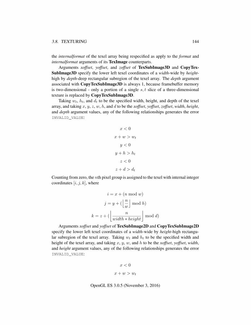
3.8. TEXTURING 144
the internalformat of the texel array being respecified as apply to the format andinternalformat arguments of its TexImage counterparts.
Arguments xoffset, yoffset, and zoffset of TexSubImage3D and CopyTex-SubImage3D specify the lower left texel coordinates of a width-wide by height-high by depth-deep rectangular subregion of the texel array. The depth argumentassociated with CopyTexSubImage3D is always 1, because framebuffer memoryis two-dimensional - only a portion of a single s, t slice of a three-dimensionaltexture is replaced by CopyTexSubImage3D.
Taking wt, ht, and dt to be the specified width, height, and depth of the texelarray, and taking x, y, z, w, h, and d to be the xoffset, yoffset, zoffset, width, height,and depth argument values, any of the following relationships generates the errorINVALID_VALUE:
x < 0
x+ w > wt
y < 0
y + h > ht
z < 0
z + d > dt
Counting from zero, the nth pixel group is assigned to the texel with internal integercoordinates [i, j, k], where
i = x+ (n mod w)
j = y + (⌊ nw
⌋mod h)
k = z + (
⌊n
width ∗ height
⌋mod d)
Arguments xoffset and yoffset of TexSubImage2D and CopyTexSubImage2Dspecify the lower left texel coordinates of a width-wide by height-high rectangu-lar subregion of the texel array. Taking wt and ht to be the specified width andheight of the texel array, and taking x, y, w, and h to be the xoffset, yoffset, width,and height argument values, any of the following relationships generates the errorINVALID_VALUE:
x < 0
x+ w > wt
OpenGL ES 3.0.5 (November 3, 2016)
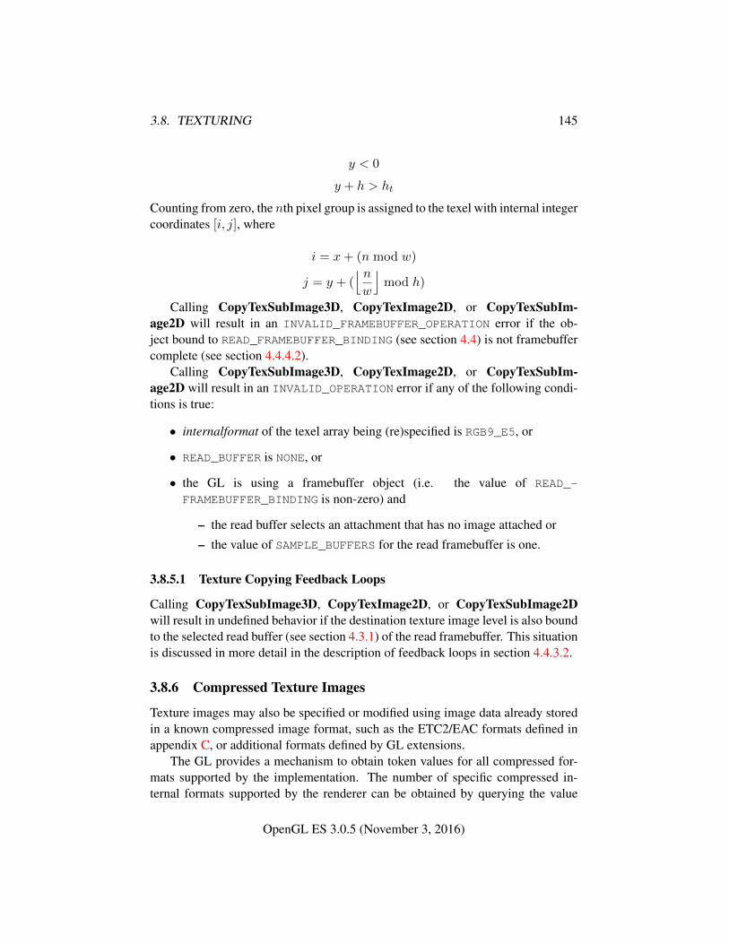
3.8. TEXTURING 145
y < 0
y + h > ht
Counting from zero, the nth pixel group is assigned to the texel with internal integercoordinates [i, j], where
i = x+ (n mod w)
j = y + (⌊ nw
⌋mod h)
Calling CopyTexSubImage3D, CopyTexImage2D, or CopyTexSubIm-age2D will result in an INVALID_FRAMEBUFFER_OPERATION error if the ob-ject bound to READ_FRAMEBUFFER_BINDING (see section 4.4) is not framebuffercomplete (see section 4.4.4.2).
Calling CopyTexSubImage3D, CopyTexImage2D, or CopyTexSubIm-age2D will result in an INVALID_OPERATION error if any of the following condi-tions is true:
• internalformat of the texel array being (re)specified is RGB9_E5, or
• READ_BUFFER is NONE, or
• the GL is using a framebuffer object (i.e. the value of READ_-
FRAMEBUFFER_BINDING is non-zero) and
– the read buffer selects an attachment that has no image attached or
– the value of SAMPLE_BUFFERS for the read framebuffer is one.
3.8.5.1 Texture Copying Feedback Loops
Calling CopyTexSubImage3D, CopyTexImage2D, or CopyTexSubImage2Dwill result in undefined behavior if the destination texture image level is also boundto the selected read buffer (see section 4.3.1) of the read framebuffer. This situationis discussed in more detail in the description of feedback loops in section 4.4.3.2.
3.8.6 Compressed Texture Images
Texture images may also be specified or modified using image data already storedin a known compressed image format, such as the ETC2/EAC formats defined inappendix C, or additional formats defined by GL extensions.
The GL provides a mechanism to obtain token values for all compressed for-mats supported by the implementation. The number of specific compressed in-ternal formats supported by the renderer can be obtained by querying the value
OpenGL ES 3.0.5 (November 3, 2016)
3.8. TEXTURING 146
of NUM_COMPRESSED_TEXTURE_FORMATS. The set of specific compressed inter-nal formats supported by the renderer can be obtained by querying the value ofCOMPRESSED_TEXTURE_FORMATS. All implementations support at least the for-mats listed in table 3.19.
The commands
void CompressedTexImage2D( enum target, int level,enum internalformat, sizei width, sizei height,int border, sizei imageSize, const void *data );
void CompressedTexImage3D( enum target, int level,enum internalformat, sizei width, sizei height,sizei depth, int border, sizei imageSize, constvoid *data );
define two-and three-dimensional texture images, respectively, with incoming datastored in a compressed image format. The target, level, internalformat, width,height, depth, and border parameters have the same meaning as in TexImage2Dand TexImage3D. data refers to compressed image data stored in the compressedimage format corresponding to internalformat. If a pixel unpack buffer is bound(as indicated by a non-zero value of PIXEL_UNPACK_BUFFER_BINDING), data isan offset into the pixel unpack buffer and the compressed data is read from thebuffer relative to this offset; otherwise, data is a pointer to client memory and thecompressed data is read from client memory relative to the pointer.
The compressed image will be decoded according to the specification definingthe internalformat token. Compressed texture images are treated as an array ofimageSize ubytes relative to data. If a pixel unpack buffer object is bound anddata + imageSize is greater than the size of the pixel buffer, an INVALID_-
OPERATION error results. All pixel storage modes are ignored when decoding acompressed texture image. If the imageSize parameter is not consistent with theformat, dimensions, and contents of the compressed image, an INVALID_VALUE
error results. If the compressed image is not encoded according to the definedimage format, the results of the call are undefined.
Compressed internal formats may impose format-specific restrictions on theuse of the compressed image specification calls or parameters. For example, thecompressed image format might be supported only for 2D textures. Any suchrestrictions will be documented in the extension specification defining the com-pressed internal format; violating these restrictions will result in an INVALID_-
OPERATION error.Any restrictions imposed by specific compressed internal formats will be in-
variant with respect to image contents, meaning that if the GL accepts and stores
OpenGL ES 3.0.5 (November 3, 2016)
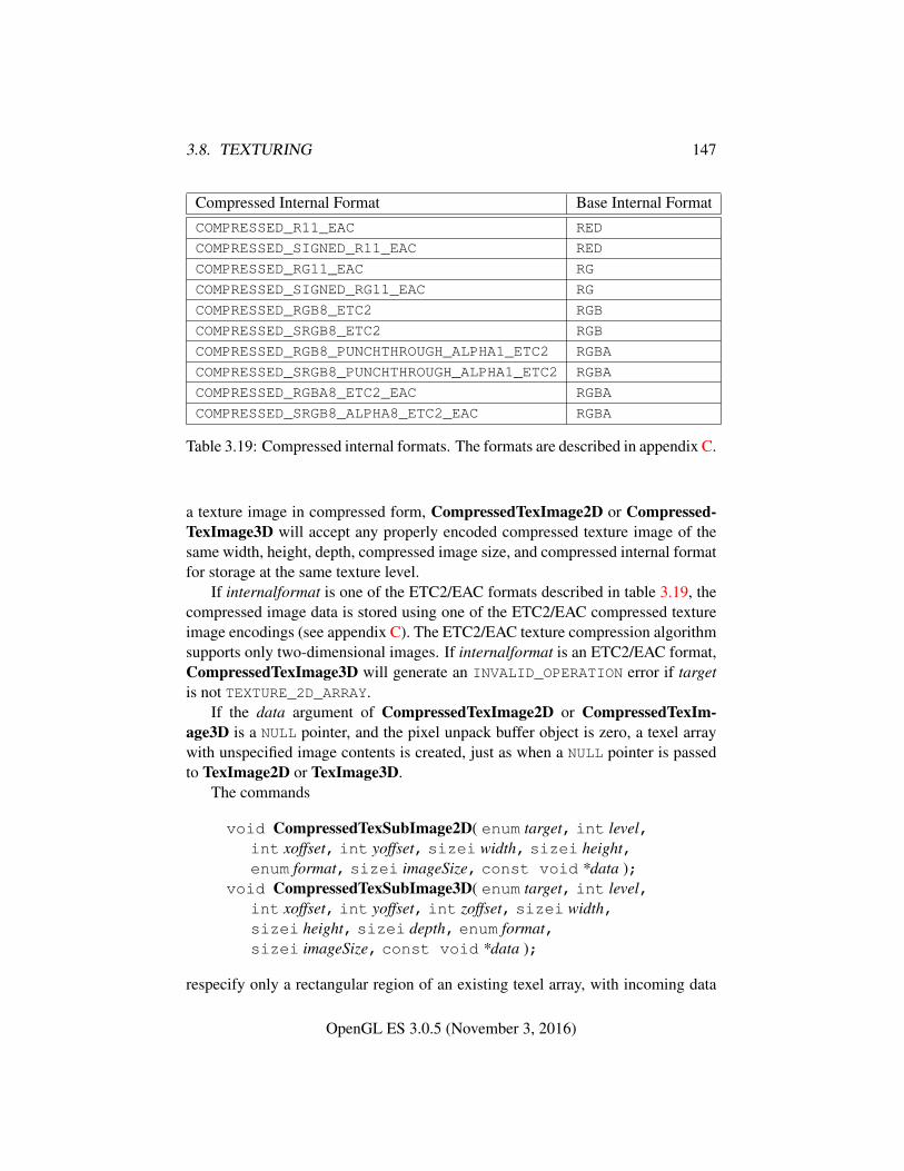
3.8. TEXTURING 147
Compressed Internal Format Base Internal FormatCOMPRESSED_R11_EAC RED
COMPRESSED_SIGNED_R11_EAC RED
COMPRESSED_RG11_EAC RG
COMPRESSED_SIGNED_RG11_EAC RG
COMPRESSED_RGB8_ETC2 RGB
COMPRESSED_SRGB8_ETC2 RGB
COMPRESSED_RGB8_PUNCHTHROUGH_ALPHA1_ETC2 RGBA
COMPRESSED_SRGB8_PUNCHTHROUGH_ALPHA1_ETC2 RGBA
COMPRESSED_RGBA8_ETC2_EAC RGBA
COMPRESSED_SRGB8_ALPHA8_ETC2_EAC RGBA
Table 3.19: Compressed internal formats. The formats are described in appendix C.
a texture image in compressed form, CompressedTexImage2D or Compressed-TexImage3D will accept any properly encoded compressed texture image of thesame width, height, depth, compressed image size, and compressed internal formatfor storage at the same texture level.
If internalformat is one of the ETC2/EAC formats described in table 3.19, thecompressed image data is stored using one of the ETC2/EAC compressed textureimage encodings (see appendix C). The ETC2/EAC texture compression algorithmsupports only two-dimensional images. If internalformat is an ETC2/EAC format,CompressedTexImage3D will generate an INVALID_OPERATION error if targetis not TEXTURE_2D_ARRAY.
If the data argument of CompressedTexImage2D or CompressedTexIm-age3D is a NULL pointer, and the pixel unpack buffer object is zero, a texel arraywith unspecified image contents is created, just as when a NULL pointer is passedto TexImage2D or TexImage3D.
The commands
void CompressedTexSubImage2D( enum target, int level,int xoffset, int yoffset, sizei width, sizei height,enum format, sizei imageSize, const void *data );
void CompressedTexSubImage3D( enum target, int level,int xoffset, int yoffset, int zoffset, sizei width,sizei height, sizei depth, enum format,sizei imageSize, const void *data );
respecify only a rectangular region of an existing texel array, with incoming data
OpenGL ES 3.0.5 (November 3, 2016)
3.8. TEXTURING 148
stored in a known compressed image format. The target, level, xoffset, yoffset,zoffset, width, height, and depth parameters have the same meaning as in Tex-SubImage2D and TexSubImage3D. data points to compressed image data storedin the compressed image format corresponding to format.
The image pointed to by data and the imageSize parameter are interpreted asthough they were provided to CompressedTexImage2D and CompressedTex-Image3D. These commands do not provide for image format conversion, so anINVALID_OPERATION error results if format does not match the internal formatof the texture image being modified. If the imageSize parameter is not consistentwith the format, dimensions, and contents of the compressed image (too little ortoo much data), an INVALID_VALUE error results.
As with CompressedTexImage calls, compressed internal formats may haveadditional restrictions on the use of the compressed image specification calls orparameters. Any such restrictions will be documented in the specification defin-ing the compressed internal format; violating these restrictions will result in anINVALID_OPERATION error.
Any restrictions imposed by specific compressed internal formats will be in-variant with respect to image contents, meaning that if GL accepts and stores a tex-ture image in compressed form, CompressedTexSubImage2D or Compressed-TexSubImage3D will accept any properly encoded compressed texture image ofthe same width, height, compressed image size, and compressed internal formatfor storage at the same texture level.
Calling CompressedTexSubImage3D or CompressedTexSubImage2D willresult in an INVALID_OPERATION error if xoffset, yoffset, or zoffset are not equalto zero, or if width, height, and depth do not match the dimensions of the texturelevel. These restrictions may be relaxed for specific compressed internal formatswhose images are easily modified.
If format is one of the ETC2/EAC formats described in table 3.19, the textureis stored using one of the ETC2/EAC compressed texture image encodings (seeappendix C). If format is an ETC2/EAC format, CompressedTexSubImage3Dwill generate an INVALID_OPERATION error if target is not TEXTURE_2D_ARRAY.Since ETC2/EAC images are easily edited along 4×4 texel boundaries, the limita-tions on subimage location and size are relaxed for CompressedTexSubImage2Dand CompressedTexSubImage3D. These commands will result in an INVALID_-OPERATION error if one of the following conditions occurs:
• width is not a multiple of four, and width + xoffset is not equal to the widthof the texture level.
• height is not a multiple of four, and height +yoffset is not equal to the heightof the texture level.
OpenGL ES 3.0.5 (November 3, 2016)
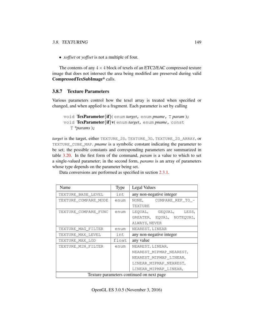
3.8. TEXTURING 149
• xoffset or yoffset is not a multiple of four.
The contents of any 4× 4 block of texels of an ETC2/EAC compressed textureimage that does not intersect the area being modified are preserved during validCompressedTexSubImage* calls.
3.8.7 Texture Parameters
Various parameters control how the texel array is treated when specified orchanged, and when applied to a fragment. Each parameter is set by calling
void TexParameter{if}( enum target, enum pname, T param );void TexParameter{if}v( enum target, enum pname, const
T *params );
target is the target, either TEXTURE_2D, TEXTURE_3D, TEXTURE_2D_ARRAY, orTEXTURE_CUBE_MAP. pname is a symbolic constant indicating the parameter tobe set; the possible constants and corresponding parameters are summarized intable 3.20. In the first form of the command, param is a value to which to seta single-valued parameter; in the second form, params is an array of parameterswhose type depends on the parameter being set.
Data conversions are performed as specified in section 2.3.1.
Name Type Legal ValuesTEXTURE_BASE_LEVEL int any non-negative integerTEXTURE_COMPARE_MODE enum NONE, COMPARE_REF_TO_-
TEXTURE
TEXTURE_COMPARE_FUNC enum LEQUAL, GEQUAL, LESS,GREATER, EQUAL, NOTEQUAL,ALWAYS, NEVER
TEXTURE_MAG_FILTER enum NEAREST, LINEARTEXTURE_MAX_LEVEL int any non-negative integerTEXTURE_MAX_LOD float any valueTEXTURE_MIN_FILTER enum NEAREST, LINEAR,
NEAREST_MIPMAP_NEAREST,NEAREST_MIPMAP_LINEAR,LINEAR_MIPMAP_NEAREST,LINEAR_MIPMAP_LINEAR,
Texture parameters continued on next page
OpenGL ES 3.0.5 (November 3, 2016)
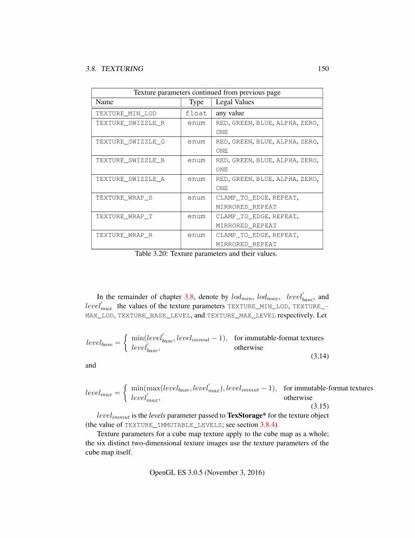
3.8. TEXTURING 150
Texture parameters continued from previous pageName Type Legal ValuesTEXTURE_MIN_LOD float any valueTEXTURE_SWIZZLE_R enum RED, GREEN, BLUE, ALPHA, ZERO,
ONE
TEXTURE_SWIZZLE_G enum RED, GREEN, BLUE, ALPHA, ZERO,ONE
TEXTURE_SWIZZLE_B enum RED, GREEN, BLUE, ALPHA, ZERO,ONE
TEXTURE_SWIZZLE_A enum RED, GREEN, BLUE, ALPHA, ZERO,ONE
TEXTURE_WRAP_S enum CLAMP_TO_EDGE, REPEAT,MIRRORED_REPEAT
TEXTURE_WRAP_T enum CLAMP_TO_EDGE, REPEAT,MIRRORED_REPEAT
TEXTURE_WRAP_R enum CLAMP_TO_EDGE, REPEAT,MIRRORED_REPEAT
Table 3.20: Texture parameters and their values.
In the remainder of chapter 3.8, denote by lodmin, lodmax, level′base, and
level′max the values of the texture parameters TEXTURE_MIN_LOD, TEXTURE_-
MAX_LOD, TEXTURE_BASE_LEVEL, and TEXTURE_MAX_LEVEL respectively. Let
levelbase =
{min(level
′base, levelimmut − 1), for immutable-format textures
level′base, otherwise
(3.14)and
levelmax =
{min(max(levelbase, level
′max), levelimmut − 1), for immutable-format textures
level′max, otherwise
(3.15)levelimmut is the levels parameter passed to TexStorage* for the texture object
(the value of TEXTURE_IMMUTABLE_LEVELS; see section 3.8.4).Texture parameters for a cube map texture apply to the cube map as a whole;
the six distinct two-dimensional texture images use the texture parameters of thecube map itself.
OpenGL ES 3.0.5 (November 3, 2016)
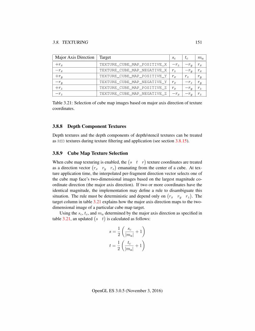
3.8. TEXTURING 151
Major Axis Direction Target sc tc ma
+rx TEXTURE_CUBE_MAP_POSITIVE_X −rz −ry rx−rx TEXTURE_CUBE_MAP_NEGATIVE_X rz −ry rx+ry TEXTURE_CUBE_MAP_POSITIVE_Y rx rz ry−ry TEXTURE_CUBE_MAP_NEGATIVE_Y rx −rz ry+rz TEXTURE_CUBE_MAP_POSITIVE_Z rx −ry rz−rz TEXTURE_CUBE_MAP_NEGATIVE_Z −rx −ry rz
Table 3.21: Selection of cube map images based on major axis direction of texturecoordinates.
3.8.8 Depth Component Textures
Depth textures and the depth components of depth/stencil textures can be treatedas RED textures during texture filtering and application (see section 3.8.15).
3.8.9 Cube Map Texture Selection
When cube map texturing is enabled, the(s t r
)texture coordinates are treated
as a direction vector(rx ry rz
)emanating from the center of a cube. At tex-
ture application time, the interpolated per-fragment direction vector selects one ofthe cube map face’s two-dimensional images based on the largest magnitude co-ordinate direction (the major axis direction). If two or more coordinates have theidentical magnitude, the implementation may define a rule to disambiguate thissituation. The rule must be deterministic and depend only on
(rx ry rz
). The
target column in table 3.21 explains how the major axis direction maps to the two-dimensional image of a particular cube map target.
Using the sc, tc, and ma determined by the major axis direction as specified intable 3.21, an updated
(s t
)is calculated as follows:
s =1
2
(sc|ma|
+ 1
)t =
1
2
(tc|ma|
+ 1
)
OpenGL ES 3.0.5 (November 3, 2016)
3.8. TEXTURING 152
3.8.9.1 Seamless Cube Map Filtering
The rules for texel selection in sections 3.8.10 through 3.8.11 are modified for cubemaps so that texture wrap modes are ignored.2 Instead,
• If NEAREST filtering is done within a miplevel, always apply wrap modeCLAMP_TO_EDGE.
• If LINEAR filtering is done within a miplevel, always apply border clamping.Then,
– If a texture sample location would lie in the texture border in either uor v, instead select the corresponding texel from the appropriate neigh-boring face.
– If a texture sample location would lie in the texture border in both uand v (in one of the corners of the cube), there is no unique neighbor-ing face from which to extract one texel. The recommended method togenerate this texel is to average the values of the three available sam-ples. However, implementations are free to construct this fourth texelin another way, so long as, when the three available samples have thesame value, this texel also has that value.
3.8.10 Texture Minification
Applying a texture to a primitive implies a mapping from texture image space toframebuffer image space. In general, this mapping involves a reconstruction ofthe sampled texture image, followed by a homogeneous warping implied by themapping to framebuffer space, then a filtering, followed finally by a resamplingof the filtered, warped, reconstructed image before applying it to a fragment. Inthe GL this mapping is approximated by one of two simple filtering schemes. Oneof these schemes is selected based on whether the mapping from texture space toframebuffer space is deemed to magnify or minify the texture image.
3.8.10.1 Scale Factor and Level of Detail
The choice is governed by a scale factor ρ(x, y) and the level-of-detail parameterλ(x, y), defined as
λbase(x, y) = log2[ρ(x, y)] (3.16)
2 This is a behavior change in OpenGL ES 3.0. In previous versions, texture wrap modes wererespected and neighboring cube map faces were not used for border texels.
OpenGL ES 3.0.5 (November 3, 2016)
3.8. TEXTURING 153
λ′(x, y) = λbase(x, y) + clamp(biasshader) (3.17)
λ =
lodmax, λ′ > lodmax
λ′, lodmin ≤ λ′ ≤ lodmax
lodmin, λ′ < lodmin
undefined, lodmin > lodmax
(3.18)
biasshader is the value of the optional bias parameter in the texture lookup functionsavailable to fragment shaders. If the texture access is performed in a fragmentshader without a provided bias, then biasshader is zero. This value is clamped tothe range [−biasmax, biasmax] where biasmax is the value of the implementation-defined constant MAX_TEXTURE_LOD_BIAS.
If λ(x, y) is less than or equal to zero the texture is said to be magnified; ifit is greater, the texture is minified. Sampling of minified textures is described inthe remainder of this section, while sampling of magnified textures is described insection 3.8.11.
The initial values of lodmin and lodmax are chosen so as to never clamp thenormal range of λ. They may be respecified for a specific texture by calling Tex-Parameter[if] with pname set to TEXTURE_MIN_LOD or TEXTURE_MAX_LOD re-spectively.
Let s(x, y) be the function that associates an s texture coordinate with each setof window coordinates (x, y) that lie within a primitive; define t(x, y) and r(x, y)analogously. Let
u(x, y) = wt × s(x, y) + δu
v(x, y) = ht × t(x, y) + δv
w(x, y) = dt × r(x, y) + δw
(3.19)
wherewt, ht, and dt are the width, height, and depth of the image array whose levelis levelbase. For a two-dimensional, two-dimensional array, or cube map texture,define w(x, y) = 0.
(δu, δv, δw) are the texel offsets specified in the OpenGL ES Shading Lan-guage texture lookup functions that support offsets. If the texture function useddoes not support offsets, all three shader offsets are taken to be zero. If anyof the offset values are outside the range of the implementation-defined valuesMIN_PROGRAM_TEXEL_OFFSET and MAX_PROGRAM_TEXEL_OFFSET, results ofthe texture lookup are undefined.
OpenGL ES 3.0.5 (November 3, 2016)
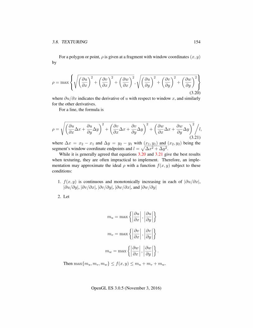
3.8. TEXTURING 154
For a polygon or point, ρ is given at a fragment with window coordinates (x, y)by
ρ = max
√(
∂u
∂x
)2
+
(∂v
∂x
)2
+
(∂w
∂x
)2
,
√(∂u
∂y
)2
+
(∂v
∂y
)2
+
(∂w
∂y
)2
(3.20)where ∂u/∂x indicates the derivative of u with respect to window x, and similarlyfor the other derivatives.
For a line, the formula is
ρ =
√(∂u
∂x∆x+
∂u
∂y∆y
)2
+
(∂v
∂x∆x+
∂v
∂y∆y
)2
+
(∂w
∂x∆x+
∂w
∂y∆y
)2/l,
(3.21)where ∆x = x2 − x1 and ∆y = y2 − y1 with (x1, y1) and (x2, y2) being thesegment’s window coordinate endpoints and l =
√∆x2 + ∆y2.
While it is generally agreed that equations 3.20 and 3.21 give the best resultswhen texturing, they are often impractical to implement. Therefore, an imple-mentation may approximate the ideal ρ with a function f(x, y) subject to theseconditions:
1. f(x, y) is continuous and monotonically increasing in each of |∂u/∂x|,|∂u/∂y|, |∂v/∂x|, |∂v/∂y|, |∂w/∂x|, and |∂w/∂y|
2. Let
mu = max
{∣∣∣∣∂u∂x∣∣∣∣ , ∣∣∣∣∂u∂y
∣∣∣∣}
mv = max
{∣∣∣∣∂v∂x∣∣∣∣ , ∣∣∣∣∂v∂y
∣∣∣∣}
mw = max
{∣∣∣∣∂w∂x∣∣∣∣ , ∣∣∣∣∂w∂y
∣∣∣∣} .Then max{mu,mv,mw} ≤ f(x, y) ≤ mu +mv +mw.
OpenGL ES 3.0.5 (November 3, 2016)
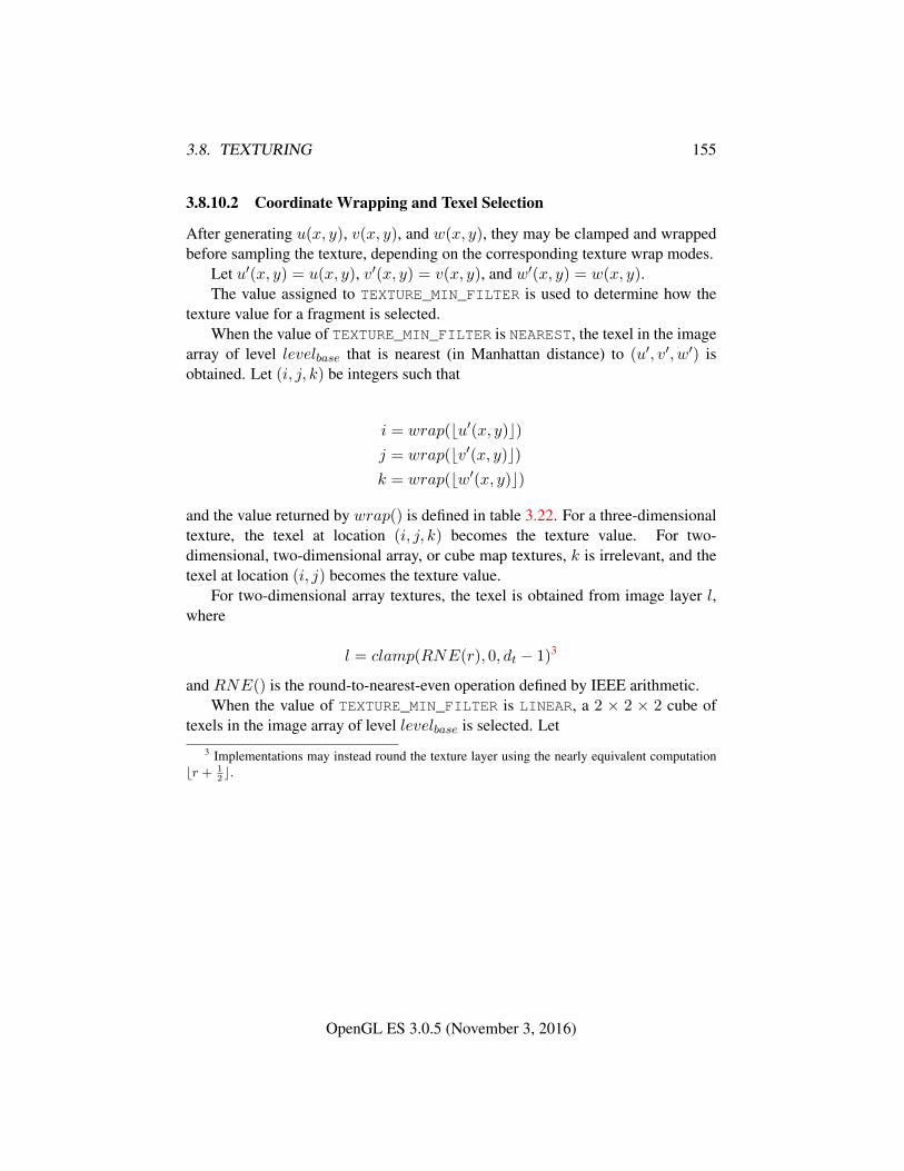
3.8. TEXTURING 155
3.8.10.2 Coordinate Wrapping and Texel Selection
After generating u(x, y), v(x, y), and w(x, y), they may be clamped and wrappedbefore sampling the texture, depending on the corresponding texture wrap modes.
Let u′(x, y) = u(x, y), v′(x, y) = v(x, y), and w′(x, y) = w(x, y).The value assigned to TEXTURE_MIN_FILTER is used to determine how the
texture value for a fragment is selected.When the value of TEXTURE_MIN_FILTER is NEAREST, the texel in the image
array of level levelbase that is nearest (in Manhattan distance) to (u′, v′, w′) isobtained. Let (i, j, k) be integers such that
i = wrap(bu′(x, y)c)j = wrap(bv′(x, y)c)k = wrap(bw′(x, y)c)
and the value returned by wrap() is defined in table 3.22. For a three-dimensionaltexture, the texel at location (i, j, k) becomes the texture value. For two-dimensional, two-dimensional array, or cube map textures, k is irrelevant, and thetexel at location (i, j) becomes the texture value.
For two-dimensional array textures, the texel is obtained from image layer l,where
l = clamp(RNE(r), 0, dt − 1)3
and RNE() is the round-to-nearest-even operation defined by IEEE arithmetic.When the value of TEXTURE_MIN_FILTER is LINEAR, a 2 × 2 × 2 cube of
texels in the image array of level levelbase is selected. Let3 Implementations may instead round the texture layer using the nearly equivalent computation
br + 12c.
OpenGL ES 3.0.5 (November 3, 2016)
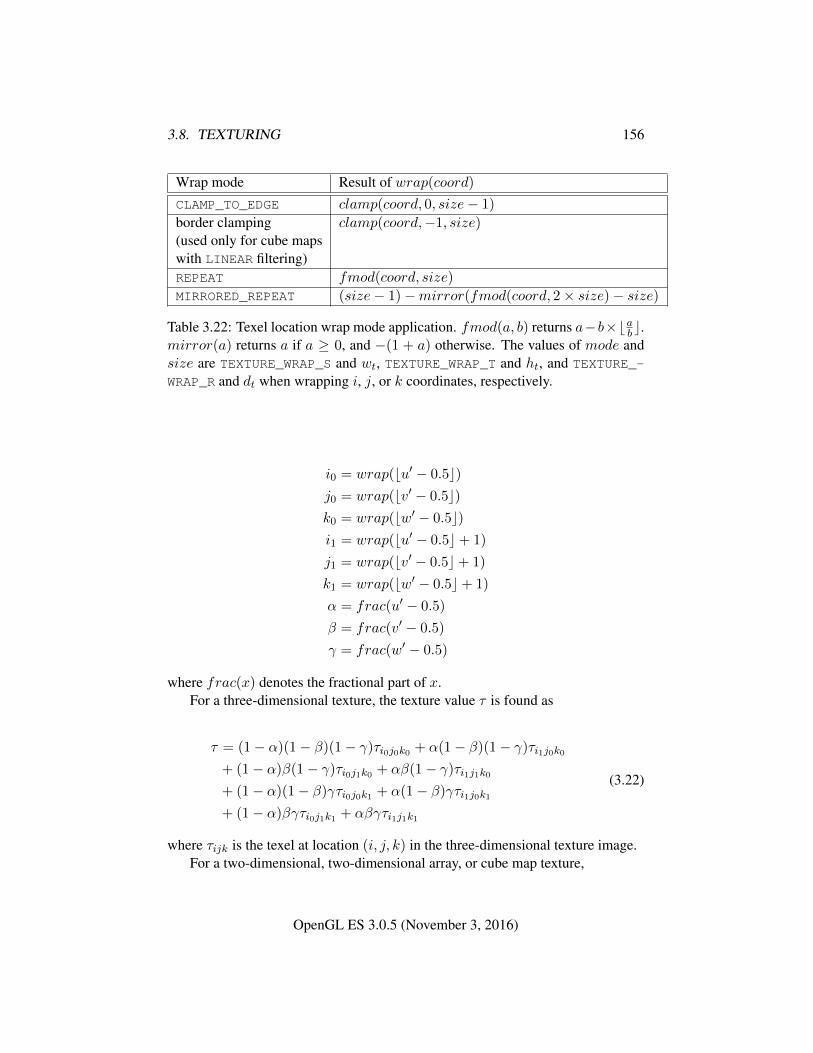
3.8. TEXTURING 156
Wrap mode Result of wrap(coord)
CLAMP_TO_EDGE clamp(coord, 0, size− 1)
border clamping clamp(coord,−1, size)(used only for cube mapswith LINEAR filtering)REPEAT fmod(coord, size)
MIRRORED_REPEAT (size− 1)−mirror(fmod(coord, 2× size)− size)
Table 3.22: Texel location wrap mode application. fmod(a, b) returns a−b×bab c.mirror(a) returns a if a ≥ 0, and −(1 + a) otherwise. The values of mode andsize are TEXTURE_WRAP_S and wt, TEXTURE_WRAP_T and ht, and TEXTURE_-
WRAP_R and dt when wrapping i, j, or k coordinates, respectively.
i0 = wrap(bu′ − 0.5c)j0 = wrap(bv′ − 0.5c)k0 = wrap(bw′ − 0.5c)i1 = wrap(bu′ − 0.5c+ 1)
j1 = wrap(bv′ − 0.5c+ 1)
k1 = wrap(bw′ − 0.5c+ 1)
α = frac(u′ − 0.5)
β = frac(v′ − 0.5)
γ = frac(w′ − 0.5)
where frac(x) denotes the fractional part of x.For a three-dimensional texture, the texture value τ is found as
τ = (1− α)(1− β)(1− γ)τi0j0k0 + α(1− β)(1− γ)τi1j0k0
+ (1− α)β(1− γ)τi0j1k0 + αβ(1− γ)τi1j1k0
+ (1− α)(1− β)γτi0j0k1 + α(1− β)γτi1j0k1
+ (1− α)βγτi0j1k1 + αβγτi1j1k1
(3.22)
where τijk is the texel at location (i, j, k) in the three-dimensional texture image.For a two-dimensional, two-dimensional array, or cube map texture,
OpenGL ES 3.0.5 (November 3, 2016)
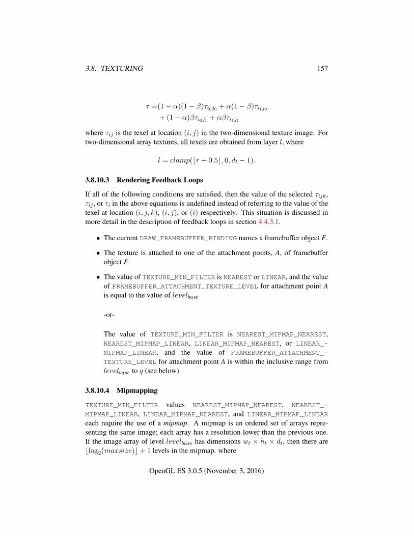
3.8. TEXTURING 157
τ =(1− α)(1− β)τi0j0 + α(1− β)τi1j0
+ (1− α)βτi0j1 + αβτi1j1
where τij is the texel at location (i, j) in the two-dimensional texture image. Fortwo-dimensional array textures, all texels are obtained from layer l, where
l = clamp(br + 0.5c, 0, dt − 1).
3.8.10.3 Rendering Feedback Loops
If all of the following conditions are satisfied, then the value of the selected τijk,τij , or τi in the above equations is undefined instead of referring to the value of thetexel at location (i, j, k), (i, j), or (i) respectively. This situation is discussed inmore detail in the description of feedback loops in section 4.4.3.1.
• The current DRAW_FRAMEBUFFER_BINDING names a framebuffer object F.
• The texture is attached to one of the attachment points, A, of framebufferobject F.
• The value of TEXTURE_MIN_FILTER is NEAREST or LINEAR, and the valueof FRAMEBUFFER_ATTACHMENT_TEXTURE_LEVEL for attachment point Ais equal to the value of levelbase
-or-
The value of TEXTURE_MIN_FILTER is NEAREST_MIPMAP_NEAREST,NEAREST_MIPMAP_LINEAR, LINEAR_MIPMAP_NEAREST, or LINEAR_-
MIPMAP_LINEAR, and the value of FRAMEBUFFER_ATTACHMENT_-
TEXTURE_LEVEL for attachment point A is within the inclusive range fromlevelbase to q (see below).
3.8.10.4 Mipmapping
TEXTURE_MIN_FILTER values NEAREST_MIPMAP_NEAREST, NEAREST_-
MIPMAP_LINEAR, LINEAR_MIPMAP_NEAREST, and LINEAR_MIPMAP_LINEAR
each require the use of a mipmap. A mipmap is an ordered set of arrays repre-senting the same image; each array has a resolution lower than the previous one.If the image array of level levelbase has dimensions wt × ht × dt, then there areblog2(maxsize)c+ 1 levels in the mipmap. where
OpenGL ES 3.0.5 (November 3, 2016)
3.8. TEXTURING 158
maxsize =
{max(wt, ht), for 2D, 2D array, and cube map texturesmax(wt, ht, dt), for 3D textures
Numbering the levels such that level levelbase is the 0th level, the ith array hasdimensions
max(1,
⌊wt
wd
⌋)×max(1,
⌊hthd
⌋)×max(1,
⌊dtdd
⌋)
where
wd = 2i
hd = 2i
dd =
{2i, for 3D textures1, otherwise
until the last array is reached with dimension 1× 1× 1.Each array in a mipmap is defined using TexImage3D, TexImage2D, Copy-
TexImage2D, or by functions that are defined in terms of these functions. Level-of-detail numbers proceed from levelbase for the original texel array through themaximum level p, with each unit increase indicating an array of half the dimen-sions of the previous one (rounded down to the next integer if fractional) as alreadydescribed. For immutable-format textures, p is one less than levelimmut. Other-wise, p = blog2(maxsize)c + levelbase, and all arrays from levelbase throughq = min{p, levelmax} must be defined, as discussed in section 3.8.13.
The values of levelbase and levelmax may be respecified for a specific tex-ture by calling TexParameter[if] with pname set to TEXTURE_BASE_LEVEL orTEXTURE_MAX_LEVEL respectively.
The error INVALID_VALUE is generated if either value is negative.The mipmap is used in conjunction with the level of detail to approximate the
application of an appropriately filtered texture to a fragment. Since this discussionpertains to minification, we are concerned only with values of λ where λ > 0.
For mipmap filters NEAREST_MIPMAP_NEAREST and LINEAR_MIPMAP_-
NEAREST, the dth mipmap array is selected, where
d =
levelbase, λ ≤ 1
2
dlevelbase + λ+ 12e − 1, λ > 1
2 , levelbase + λ ≤ q + 12
4
q, λ > 12 , levelbase + λ > q + 1
2
(3.23)
OpenGL ES 3.0.5 (November 3, 2016)
3.8. TEXTURING 159
The rules for NEAREST or LINEAR filtering are then applied to the selectedarray. Specifically, the coordinate (u, v, w) is computed as in equation 3.19, withwt, ht, and dt equal to the width, height, and depth of the image array whose levelis d.
For mipmap filters NEAREST_MIPMAP_LINEAR and LINEAR_MIPMAP_-
LINEAR, the level d1 and d2 mipmap arrays are selected, where
d1 =
{q, levelbase + λ ≥ qblevelbase + λc, otherwise
(3.24)
d2 =
{q, levelbase + λ ≥ qd1 + 1, otherwise
(3.25)
The rules for NEAREST or LINEAR filtering are then applied to each of theselected arrays, yielding two corresponding texture values τ1 and τ2. Specifically,for level d1, the coordinate (u, v, w) is computed as in equation 3.19, with wt, ht,and dt equal to the width, height, and depth of the image array whose level is d1.For level d2 the coordinate (u′, v′, w′) is computed as in equation 3.19, with wt,ht, and dt equal to the width, height, and depth of the image array whose level isd2.
The final texture value is then found as
τ = [1− frac(λ)]τ1 + frac(λ)τ2.
3.8.10.5 Manual Mipmap Generation
Mipmaps can be generated manually with the command
void GenerateMipmap( enum target );
where target is one of TEXTURE_2D, TEXTURE_3D, TEXTURE_2D_ARRAY, orTEXTURE_CUBE_MAP. Mipmap generation affects the texture image attached totarget. For cube map textures, an INVALID_OPERATION error is generated if thetexture bound to target is not cube complete, as defined in section 3.8.13.
Mipmap generation replaces texel array levels levelbase + 1 through q witharrays derived from the levelbase array, regardless of their previous contents. Allother mipmap arrays, including the levelbase array, are left unchanged by this com-putation.
4 Implementations may instead use the nearly equivalent computation d = blevelbase + λ+ 12c
in this case.
OpenGL ES 3.0.5 (November 3, 2016)
3.8. TEXTURING 160
The internal formats and effective internal formats of the derived mipmap ar-rays all match those of the levelbase array, and the dimensions of the derived arraysfollow the requirements described in section 3.8.13.
The contents of the derived arrays are computed by repeated, filtered reductionof the levelbase array. For two-dimensional array textures, each layer is filteredindependently. No particular filter algorithm is required, though a box filter isrecommended.
If the levelbase array was not specified with an unsized internal format from ta-ble 3.3 or a sized internal format that is both color-renderable and texture-filterableaccording to table 3.13, an INVALID_OPERATION error is generated.
3.8.11 Texture Magnification
When λ indicates magnification, the value assigned to TEXTURE_MAG_FILTER
determines how the texture value is obtained. There are two possible valuesfor TEXTURE_MAG_FILTER: NEAREST and LINEAR. NEAREST behaves exactly asNEAREST for TEXTURE_MIN_FILTER and LINEAR behaves exactly as LINEAR forTEXTURE_MIN_FILTER as described in section 3.8.10, including the texture coor-dinate wrap modes specified in table 3.22. The level-of-detail levelbase texel arrayis always used for magnification.
3.8.12 Combined Depth/Stencil Textures
If the texture image has a base internal format of DEPTH_STENCIL, then the sten-cil texture component is ignored. The texture value τ does not include a stencilcomponent, but includes only the depth component.
3.8.13 Texture Completeness
A texture is said to be complete if all the image arrays and texture parametersrequired to utilize the texture for texture application are consistently defined. Thedefinition of completeness varies depending on texture dimensionality and type.
For two-and three-dimensional textures and two-dimensional array textures, atexture is mipmap complete if all of the following conditions hold true:
• The set of mipmap arrays levelbase through q (where q is defined in theMipmapping discussion of section 3.8.10) were each specified with thesame effective internal format.
• The dimensions of the arrays follow the sequence described in the Mipmap-ping discussion of section 3.8.10.
OpenGL ES 3.0.5 (November 3, 2016)
3.8. TEXTURING 161
• levelbase ≤ levelmax
Array levels k where k < levelbase or k > q are insignificant to the definition ofcompleteness.
A cube map texture is mipmap complete if each of the six texture images,considered individually, is mipmap complete. Additionally, a cube map texture iscube complete if the following conditions all hold true:
• The levelbase arrays of each of the six texture images making up the cubemap have identical, positive, and square dimensions.
• The levelbase arrays were each specified with the same effective internalformat.
Using the preceding definitions, a texture is complete unless any of the follow-ing conditions hold true:
• Any dimension of the levelbase array is not positive.
• The texture is a cube map texture, and is not cube complete.
• The minification filter requires a mipmap (is neither NEAREST nor LINEAR),and the texture is not mipmap complete.
• The effective internal format specified for the texture arrays is a sized in-ternal color format that is not texture-filterable (see table 3.13), and eitherthe magnification filter is not NEAREST or the minification filter is neitherNEAREST nor NEAREST_MIPMAP_NEAREST.
• The effective internal format specified for the texture arrays is a sizedinternal depth or depth and stencil format (see table 3.14), the value ofTEXTURE_COMPARE_MODE is NONE, and either the magnification filter isnot NEAREST or the minification filter is neither NEAREST nor NEAREST_-MIPMAP_NEAREST.
3.8.13.1 Effects of Sampler Objects on Texture Completeness
If a sampler object and a texture object are simultaneously bound to the same tex-ture unit, then the sampling state for that unit is taken from the sampler object (seesection 3.8.2). This can have an effect on the effective completeness of the texture.In particular, if the texture is not mipmap complete and the sampler object speci-fies a TEXTURE_MIN_FILTER requiring mipmaps, the texture will be considered
OpenGL ES 3.0.5 (November 3, 2016)
3.8. TEXTURING 162
incomplete for the purposes of that texture unit. However, if the sampler objectdoes not require mipmaps, the texture object will be considered complete. Thismeans that a texture can be considered both complete and incomplete simultane-ously if it is bound to two or more texture units along with sampler objects withdifferent states.
3.8.13.2 Effects of Completeness on Texture Application
Texture lookup and texture fetch operations performed in vertex and fragmentshaders are affected by completeness of the texture being sampled as describedin sections 2.12.9.4 and 3.9.2.1.
3.8.13.3 Effects of Completeness on Texture Image Specification
The implementation-dependent maximum sizes for texture image arrays dependon the texture level. In particular, an implementation may allow a texture imagearray of level 1 or greater to be created only if a mipmap complete set of imagearrays consistent with the requested array can be supported where the values ofTEXTURE_BASE_LEVEL and TEXTURE_MAX_LEVEL are 0 and 1000 respectively.As a result, implementations may permit a texture image array at level zero that willnever be mipmap complete and can only be used with non-mipmapped minificationfilters.
3.8.14 Texture State
The state necessary for texture can be divided into two categories. First, there arethe multiple sets of texel arrays (one set of mipmap arrays each for the two-andthree-dimensional texture and two-dimensional array texture targets; and six setsof mipmap arrays for the cube map texture targets) and their number. Each ar-ray has associated with it a width, height, and depth (three-dimensional and two-dimensional array only), an integer describing the internal format of the image,integer values describing the resolutions of each of the red, green, blue, alpha,depth, and stencil components of the image, integer values describing the type(unsigned normalized, integer, floating-point, etc.) of each of the components, aboolean describing whether the image is compressed or not, and an integer sizeof a compressed image. Each initial texel array is null (zero width, height, anddepth, internal format RGBA, component sizes set to zero and component types setto NONE, the compressed flag set to FALSE, and a zero compressed size).
Next, there are the four sets of texture properties, corresponding to the two-dimensional, two-dimensional array, three-dimensional, and cube map texture tar-gets. Each set consists of the selected minification and magnification filters, the
OpenGL ES 3.0.5 (November 3, 2016)
3.8. TEXTURING 163
wrap modes for s, t, and r (three-dimensional only), two floating-point numbersdescribing the minimum and maximum level of detail, two integers describing thebase and maximum mipmap array, a boolean flag indicating whether the formatand dimensions of the texture are immutable, two integers describing the comparemode and compare function (see section 3.8.15), and four integers describing thered, green, blue, and alpha swizzle modes (see section 3.9.2.1). In the initial state,the value assigned to TEXTURE_MIN_FILTER is NEAREST_MIPMAP_LINEAR andthe value for TEXTURE_MAG_FILTER is LINEAR. s, t, and r wrap modes are all setto REPEAT. The values of TEXTURE_MIN_LOD and TEXTURE_MAX_LOD are -1000and 1000 respectively. The values of TEXTURE_BASE_LEVEL and TEXTURE_-
MAX_LEVEL are 0 and 1000 respectively. The value of TEXTURE_IMMUTABLE_-FORMAT is FALSE. The value of TEXTURE_IMMUTABLE_LEVELS is 0. Thevalues of TEXTURE_COMPARE_MODE and TEXTURE_COMPARE_FUNC are NONE
and LEQUAL respectively. The values of TEXTURE_SWIZZLE_R, TEXTURE_-SWIZZLE_G, TEXTURE_SWIZZLE_B, and TEXTURE_SWIZZLE_A are RED, GREEN,BLUE, and ALPHA, respectively.
3.8.15 Texture Comparison Modes
Texture values can also be computed according to a specified comparison function.Texture parameter TEXTURE_COMPARE_MODE specifies the comparison operands,and parameter TEXTURE_COMPARE_FUNC specifies the comparison function.
3.8.15.1 Depth Texture Comparison Mode
If the currently bound texture’s base internal format is DEPTH_COMPONENT orDEPTH_STENCIL, then TEXTURE_COMPARE_MODE and TEXTURE_COMPARE_-
FUNC control the output of the texture unit as described below. Otherwise, thetexture unit operates in the normal manner and texture comparison is bypassed.
Let Dt be the depth texture value and Dref be the reference value, provided bythe shader’s texture lookup function.
If the texture’s internal format indicates a fixed-point depth texture, then Dt
and Dref are clamped to the range [0, 1]; otherwise no clamping is performed.Then the effective texture value is computed as follows:
If the value of TEXTURE_COMPARE_MODE is NONE, then
r = Dt
If the value of TEXTURE_COMPARE_MODE is COMPARE_REF_TO_TEXTURE,then r depends on the texture comparison function as shown in table 3.23.
The resulting r is assigned to Rt.
OpenGL ES 3.0.5 (November 3, 2016)
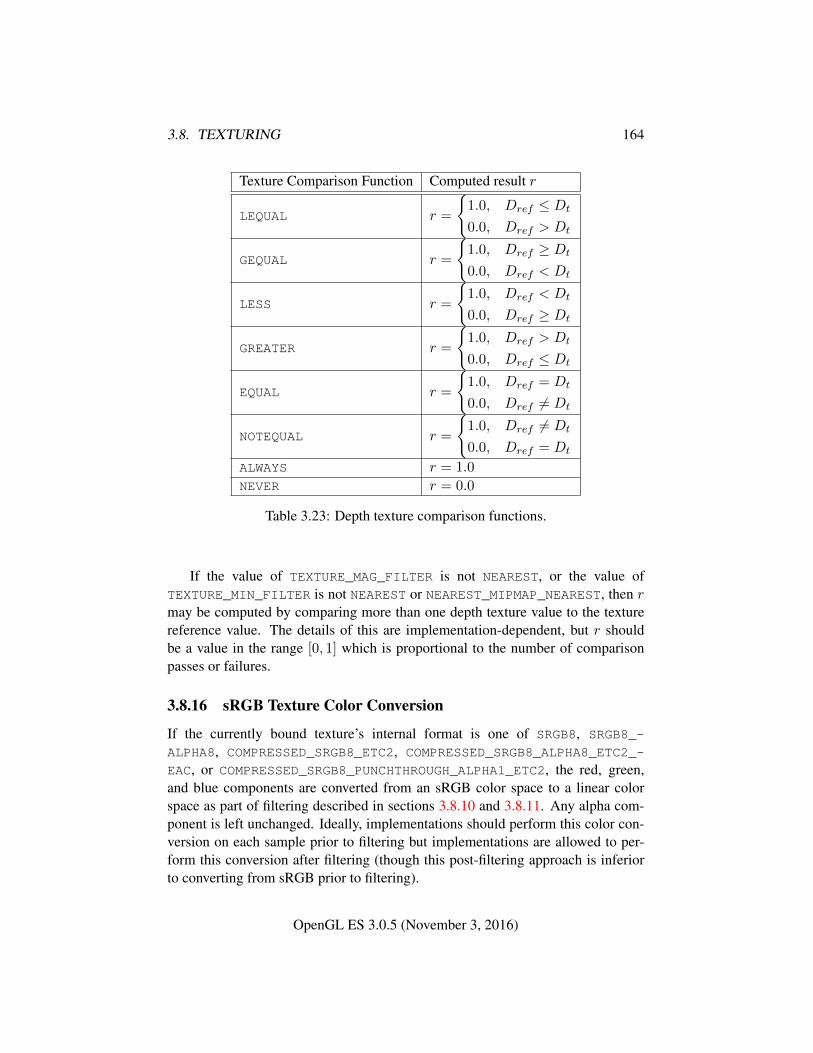
3.8. TEXTURING 164
Texture Comparison Function Computed result r
LEQUAL r =
{1.0, Dref ≤ Dt
0.0, Dref > Dt
GEQUAL r =
{1.0, Dref ≥ Dt
0.0, Dref < Dt
LESS r =
{1.0, Dref < Dt
0.0, Dref ≥ Dt
GREATER r =
{1.0, Dref > Dt
0.0, Dref ≤ Dt
EQUAL r =
{1.0, Dref = Dt
0.0, Dref 6= Dt
NOTEQUAL r =
{1.0, Dref 6= Dt
0.0, Dref = Dt
ALWAYS r = 1.0
NEVER r = 0.0
Table 3.23: Depth texture comparison functions.
If the value of TEXTURE_MAG_FILTER is not NEAREST, or the value ofTEXTURE_MIN_FILTER is not NEAREST or NEAREST_MIPMAP_NEAREST, then rmay be computed by comparing more than one depth texture value to the texturereference value. The details of this are implementation-dependent, but r shouldbe a value in the range [0, 1] which is proportional to the number of comparisonpasses or failures.
3.8.16 sRGB Texture Color Conversion
If the currently bound texture’s internal format is one of SRGB8, SRGB8_-
ALPHA8, COMPRESSED_SRGB8_ETC2, COMPRESSED_SRGB8_ALPHA8_ETC2_-
EAC, or COMPRESSED_SRGB8_PUNCHTHROUGH_ALPHA1_ETC2, the red, green,and blue components are converted from an sRGB color space to a linear colorspace as part of filtering described in sections 3.8.10 and 3.8.11. Any alpha com-ponent is left unchanged. Ideally, implementations should perform this color con-version on each sample prior to filtering but implementations are allowed to per-form this conversion after filtering (though this post-filtering approach is inferiorto converting from sRGB prior to filtering).
OpenGL ES 3.0.5 (November 3, 2016)
3.9. FRAGMENT SHADERS 165
The conversion from an sRGB encoded component, cs, to a linear component,cl, is as follows. Assume cs is the sRGB component in the range [0, 1].
cl =
{cs
12.92 , cs ≤ 0.04045(cs+0.0551.055
)2.4, cs > 0.04045
(3.26)
3.8.17 Shared Exponent Texture Color Conversion
If the currently bound texture’s internal format is RGB9_E5, the red, green, blue,and shared bits are converted to color components (prior to filtering) using sharedexponent decoding. The component reds, greens, blues, and exps values (seesection 3.8.3.2) are treated as unsigned integers and are converted to floating-pointred, green, and blue as follows:
red = reds2exps−B−N
green = greens2exps−B−N
blue = blues2exps−B−N
3.9 Fragment Shaders
The sequence of operations that are applied to fragments that result from rasterizinga point, line segment, or polygon are described using a fragment shader.
A fragment shader is an array of strings containing source code for the op-erations that are meant to occur on each fragment that results from rasterization.The language used for fragment shaders is described in the OpenGL ES ShadingLanguage Specification.
Fragment shaders are created as described in section 2.12.1 using a type pa-rameter of FRAGMENT_SHADER. They are attached to and used in program objectsas described in section 2.12.3.
When a linked program object is used as the current program object, the ex-ecutable code for the fragment shader it contains is used to process fragments. Ifno program object is currently in use, the results of fragment shader execution areundefined.
3.9.1 Shader Variables
Fragment shaders can access uniforms belonging to the current shader object. Theamount of storage available for fragment shader uniform variables in the default
OpenGL ES 3.0.5 (November 3, 2016)
3.9. FRAGMENT SHADERS 166
uniform block is specified by the value of the implementation-dependent con-stant MAX_FRAGMENT_UNIFORM_COMPONENTS. The implementation-dependentconstant MAX_FRAGMENT_UNIFORM_VECTORS has a value equal to the value ofMAX_FRAGMENT_UNIFORM_COMPONENTS divided by four. The total amount ofcombined storage available for fragment shader uniform variables in all uni-form blocks (including the default uniform block) is specified by the value ofthe implementation-dependent constant MAX_COMBINED_FRAGMENT_UNIFORM_-COMPONENTS. These values represent the numbers of individual floating-point, in-teger, or boolean values that can be held in uniform variable storage for a fragmentshader. A uniform matrix will consume no more than 4 ×min(r, c) such values,where r and c are the number of rows and columns in the matrix. A link errorwill be generated if an attempt is made to utilize more than the space available forfragment shader uniform variables.
Fragment shaders can read input variables or inputs that correspond to theattributes of the fragments produced by rasterization. The OpenGL ES ShadingLanguage Specification defines a set of built-in inputs that can be be accessed bya fragment shader. These built-in inputs include data associated with a fragmentsuch as the fragment’s position.
Additionally, when a vertex shader is active, it may define one or more outputvariables (see section 2.12.8 and the OpenGL ES Shading Language Specification).The values of these user-defined outputs are, if not flat shaded, interpolated acrossthe primitive being rendered. The results of these interpolations are available wheninputs of the same name are defined in the fragment shader.
When interpolating input variables, the default screen-space location at whichthese variables are sampled is defined in previous rasterization sections. Thedefault location may be overriden by interpolation qualifiers. When interpolat-ing variables declared using centroid in, the variable is sampled at a locationwithin the pixel covered by the primitive generating the fragment.
A fragment shader can also write to output variables. Values written to theseoutputs are used in the subsequent per-fragment operations. Output variables canbe used to write floating-point, integer or unsigned integer values destined forbuffers attached to a framebuffer object, or destined for color buffers attached to thedefault framebuffer. The Shader Outputs subsection of section 3.9.2.3 describeshow to direct these values to buffers.
3.9.2 Shader Execution
The executable version of the fragment shader is used to process incoming frag-ment values that are the result of rasterization.
OpenGL ES 3.0.5 (November 3, 2016)
3.9. FRAGMENT SHADERS 167
3.9.2.1 Texture Access
The Shader Only Texturing subsection of section 2.12.9.1 describes texturelookup functionality accessible to a vertex shader. The texel fetch and texture sizequery functionality described there also applies to fragment shaders.
When a texture lookup is performed in a fragment shader, the GL computesthe filtered texture value τ in the manner described in sections 3.8.10 and 3.8.11,and converts it to a texture base color Cb as shown in table 3.24, followedby swizzling the components of Cb, controlled by the values of the texture pa-rameters TEXTURE_SWIZZLE_R, TEXTURE_SWIZZLE_G, TEXTURE_SWIZZLE_B,and TEXTURE_SWIZZLE_A. If the value of TEXTURE_SWIZZLE_R is denoted byswizzler, swizzling computes the first component of Cs according to
if (swizzler == RED)Cs[0] = Cb[0];
else if (swizzler == GREEN)Cs[0] = Cb[1];
else if (swizzler == BLUE)Cs[0] = Cb[2];
else if (swizzler == ALPHA)Cs[0] = Ab;
else if (swizzler == ZERO)Cs[0] = 0;
else if (swizzler == ONE)Cs[0] = 1; // float or int depending on texture component type
Swizzling of Cs[1], Cs[2], and As are similarly controlled by the values ofTEXTURE_SWIZZLE_G, TEXTURE_SWIZZLE_B, and TEXTURE_SWIZZLE_A, re-spectively.
The resulting four-component vector (Rs, Gs, Bs, As) is returned to the frag-ment shader. For the purposes of level-of-detail calculations, the derivatives du
dx , dudy ,
dvdx , dv
dy , dwdx and dw
dy may be approximated by a differencing algorithm as detailed insection 8.8 of the OpenGL ES Shading Language Specification.
Texture lookups involving textures with depth component data generate a tex-ture base color Cb either using depth data directly or by performing a comparisonwith the Dref value used to perform the lookup, as described in section 3.8.15.1.The resulting value Rt is then expanded to a color Cb = (Rt, 0, 0, 1), and swiz-zling is performed as described in section 3.9.2.1, but only the first componentCs[0] is returned to the shader when a comparison has been performed. The com-parison operation is requested in the shader by using any of the shadow sampler
OpenGL ES 3.0.5 (November 3, 2016)
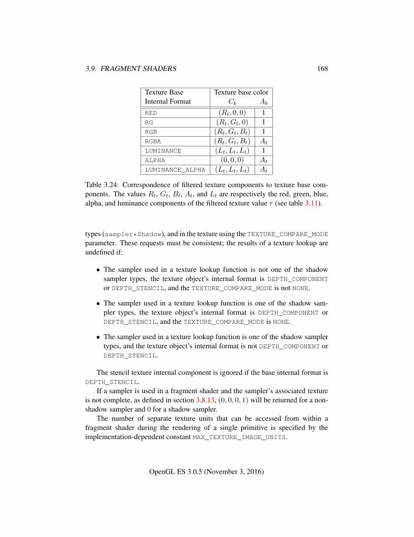
3.9. FRAGMENT SHADERS 168
Texture Base Texture base colorInternal Format Cb Ab
RED (Rt, 0, 0) 1RG (Rt, Gt, 0) 1RGB (Rt, Gt, Bt) 1RGBA (Rt, Gt, Bt) At
LUMINANCE (Lt, Lt, Lt) 1ALPHA (0, 0, 0) At
LUMINANCE_ALPHA (Lt, Lt, Lt) At
Table 3.24: Correspondence of filtered texture components to texture base com-ponents. The values Rt, Gt, Bt, At, and Lt are respectively the red, green, blue,alpha, and luminance components of the filtered texture value τ (see table 3.11).
types (sampler*Shadow), and in the texture using the TEXTURE_COMPARE_MODEparameter. These requests must be consistent; the results of a texture lookup areundefined if:
• The sampler used in a texture lookup function is not one of the shadowsampler types, the texture object’s internal format is DEPTH_COMPONENT
or DEPTH_STENCIL, and the TEXTURE_COMPARE_MODE is not NONE.
• The sampler used in a texture lookup function is one of the shadow sam-pler types, the texture object’s internal format is DEPTH_COMPONENT orDEPTH_STENCIL, and the TEXTURE_COMPARE_MODE is NONE.
• The sampler used in a texture lookup function is one of the shadow samplertypes, and the texture object’s internal format is not DEPTH_COMPONENT orDEPTH_STENCIL.
The stencil texture internal component is ignored if the base internal format isDEPTH_STENCIL.
If a sampler is used in a fragment shader and the sampler’s associated textureis not complete, as defined in section 3.8.13, (0, 0, 0, 1) will be returned for a non-shadow sampler and 0 for a shadow sampler.
The number of separate texture units that can be accessed from within afragment shader during the rendering of a single primitive is specified by theimplementation-dependent constant MAX_TEXTURE_IMAGE_UNITS.
OpenGL ES 3.0.5 (November 3, 2016)
3.9. FRAGMENT SHADERS 169
3.9.2.2 Shader Inputs
The OpenGL ES Shading Language Specification describes the values that areavailable as inputs to the fragment shader.
The built-in variable gl_FragCoord holds the fragment coordinate(xw yw zw
1wc
)for the fragment where
(xw yw zw
)is the fragment’s
window-space position and wc is the w component of the fragment’s clip-spaceposition (see section 2.13). The zw component of gl_FragCoord undergoes animplied conversion to floating-point. This conversion must leave the values 0 and1 invariant. Note that zw already has a polygon offset added in, if enabled (seesection 3.6.2).
The built-in variable gl_FrontFacing is set to TRUE if the fragment is gener-ated from a front-facing primitive, and FALSE otherwise. For fragments generatedfrom triangle primitives, the determination is made by examining the sign of thearea computed by equation 3.6 of section 3.6.1 (including the possible reversal ofthis sign controlled by FrontFace). If the sign is positive, fragments generated bythe primitive are front-facing; otherwise, they are back-facing. All other fragmentsare considered front-facing.
There is a limit on the number of components of built-in and user-definedinput variables that can be read by the fragment shader, given by the value ofthe implementation-dependent constant MAX_FRAGMENT_INPUT_COMPONENTS.When a program is linked, all components of any input variables read by a fragmentshader will count against this limit. A program whose fragment shader exceeds thislimit may fail to link, unless device-dependent optimizations are able to make theprogram fit within available hardware resources.
Component counting rules for different variable types and variable declarationsare the same as for MAX_VERTEX_OUTPUT_COMPONENTS. (see section 2.12.8).
3.9.2.3 Shader Outputs
The OpenGL ES Shading Language Specification describes the values that maybe output by a fragment shader. These outputs are split into two categories,user-defined outputs and the built-in outputs gl_FragColor, gl_FragData[n](both available only in OpenGL ES Shading Language version 1.00), and gl_-
FragDepth. For fixed-point depth buffers, the final fragment depth written by afragment shader is first clamped to [0, 1] and then converted to fixed-point as if itwere a window z value (see section 2.13.1). For floating-point depth buffers, con-version is not performed but clamping is. Note that the depth range computation isnot applied here, only the conversion to fixed-point.
If there is only a single output variable, it does not need to be explicitly bound
OpenGL ES 3.0.5 (November 3, 2016)
3.9. FRAGMENT SHADERS 170
to a fragment color within the shader text, in which case it is implicitly bound tofragment color zero. If there is more than one output variable, all output variablesmust be explicitly bound to fragment colors within the shader text. Missing orconflicting binding assignments will cause CompileShader to fail.
Color values written by a fragment shader may be floating-point, signed inte-ger, or unsigned integer. If the color buffer has a signed or unsigned normalizedfixed-point format, color values are assumed to be floating-point and are convertedto fixed-point as described in equations 2.4 or 2.3, respectively; otherwise no typeconversion is applied. If the values written by the fragment shader do not matchthe format(s) of the corresponding color buffer(s), the result is undefined.
Writing to gl_FragColor specifies the fragment color (color number zero)that will be used by subsequent stages of the pipeline. Writing to gl_-
FragData[n] specifies the value of fragment color number n (see section 4.2.1).Any colors, or color components, associated with a fragment that are not writtenby the fragment shader are undefined. A fragment shader may not statically as-sign values to both gl_FragColor and gl_FragData. In this case, a compileor link error will result. A shader statically assigns a value to a variable if, afterpre-processing, it contains a statement that would write to the variable, whether ornot run-time flow of control will cause that statement to be executed.
Writing to gl_FragDepth specifies the depth value for the fragment beingprocessed. If the active fragment shader does not statically assign a value to gl_-
FragDepth, then the depth value generated during rasterization is used by sub-sequent stages of the pipeline. Otherwise, the value assigned to gl_FragDepth
is used, and is undefined for any fragments where statements assigning a value togl_FragDepth are not executed. Thus, if a shader statically assigns a value togl_FragDepth, then it is responsible for always writing it.
After a program object has been linked successfully, the bindings of outputvariable names to color numbers can be queried. The command
int GetFragDataLocation( uint program, constchar *name );
returns the number of the fragment color to which the output variable name wasbound when the program object program was last linked. name must be a null-terminated string. If program has not been linked, or was last linked unsuccessfully,the error INVALID_OPERATION is generated. If name is not an output variable, orif an error occurs, -1 will be returned.
OpenGL ES 3.0.5 (November 3, 2016)
Chapter 4
Per-Fragment Operations and theFramebuffer
The framebuffer , whether it is the default framebuffer or a framebuffer object (seesection 2.1), consists of a set of pixels arranged as a two-dimensional array. Forpurposes of this discussion, each pixel in the framebuffer is simply a set of somenumber of bits. The number of bits per pixel may vary depending on the GL im-plementation, the type of framebuffer selected, and parameters specified when theframebuffer was created. Creation and management of the default framebuffer isoutside the scope of this specification, while creation and management of frame-buffer objects is described in detail in section 4.4.
Corresponding bits from each pixel in the framebuffer are grouped togetherinto a bitplane; each bitplane contains a single bit from each pixel. These bitplanesare grouped into several logical buffers. These are the color, depth, and stencilbuffers. The color buffer actually consists of a number of buffers, and these colorbuffers serve related but slightly different purposes depending on whether the GLis bound to the default framebuffer or a framebuffer object.
For the default framebuffer, the color buffers are the front and the back buffers.Typically the contents of the front buffer are displayed on a color monitor whilethe contents of the back buffer are invisible; the GL draws to and reads from theback buffer. All color buffers must have the same number of bitplanes, althoughan implementation or context may choose not to provide back buffers. Further, animplementation or context may choose not to provide depth or stencil buffers. Ifno default framebuffer is associated with the GL context, the framebuffer is incom-plete except when a framebuffer object is bound (see sections 4.4.1 and 4.4.4).
Framebuffer objects are not visible, and do not have any of the color bufferspresent in the default framebuffer. Instead, the buffers of a framebuffer object are
171
4.1. PER-FRAGMENT OPERATIONS 172
specified by attaching individual textures or renderbuffers (see section 4.4) to a setof attachment points. A framebuffer object has an array of color buffer attachmentpoints, numbered zero through n, a depth buffer attachment point, and a stencilbuffer attachment point. In order to be used for rendering, a framebuffer objectmust be complete, as described in section 4.4.4. Not all attachment points of aframebuffer object need to be populated.
Each pixel in a color buffer consists of up to four color components. The fourcolor components are named R, G, B, and A, in that order; color buffers are notrequired to have all four color components. R, G, B, and A components may be rep-resented as unsigned normalized fixed-point or signed or unsigned integer values;all components must have the same representation. Each pixel in a depth bufferconsists of a single unsigned integer value in the format described in section 2.13.1or a floating-point value. Each pixel in a stencil buffer consists of a single unsignedinteger value.
The number of bitplanes in the color, depth, and stencil buffers is dependenton the currently bound framebuffer. For the default framebuffer, the number ofbitplanes is fixed. For framebuffer objects, the number of bitplanes in a givenlogical buffer may change if the image attached to the corresponding attachmentpoint changes.
The GL has two active framebuffers; the draw framebuffer is the destinationfor rendering operations, and the read framebuffer is the source for readback op-erations. The same framebuffer may be used for both drawing and reading. Sec-tion 4.4.1 describes the mechanism for controlling framebuffer usage.
The default framebuffer is initially used as the draw and read framebuffer 1,and the initial state of all provided bitplanes is undefined. The format and encod-ing of buffers in the draw and read framebuffers can be queried as described insection 6.1.13.
4.1 Per-Fragment Operations
A fragment produced by rasterization with window coordinates of (xw, yw) mod-ifies the pixel in the framebuffer at that location based on a number of parametersand conditions. We describe these modifications and tests, diagrammed in fig-ure 4.1, in the order in which they are performed.
1The window system binding API may allow associating a GL context with two separate “defaultframebuffers” provided by the window system as the draw and read framebuffers, but if so, bothdefault framebuffers are referred to by the name zero at their respective binding points.
OpenGL ES 3.0.5 (November 3, 2016)
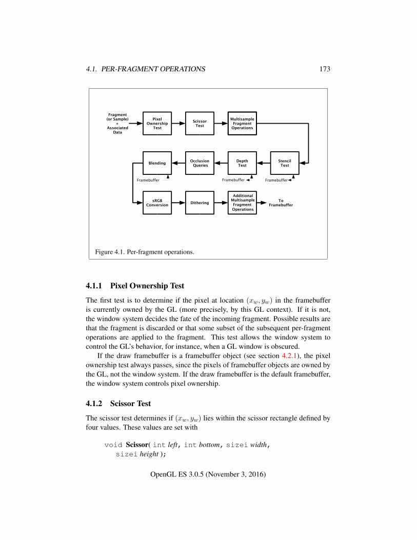
4.1. PER-FRAGMENT OPERATIONS 173
Figure 4.1. Per-fragment operations.
4.1.1 Pixel Ownership Test
The first test is to determine if the pixel at location (xw, yw) in the framebufferis currently owned by the GL (more precisely, by this GL context). If it is not,the window system decides the fate of the incoming fragment. Possible results arethat the fragment is discarded or that some subset of the subsequent per-fragmentoperations are applied to the fragment. This test allows the window system tocontrol the GL’s behavior, for instance, when a GL window is obscured.
If the draw framebuffer is a framebuffer object (see section 4.2.1), the pixelownership test always passes, since the pixels of framebuffer objects are owned bythe GL, not the window system. If the draw framebuffer is the default framebuffer,the window system controls pixel ownership.
4.1.2 Scissor Test
The scissor test determines if (xw, yw) lies within the scissor rectangle defined byfour values. These values are set with
void Scissor( int left, int bottom, sizei width,sizei height );
OpenGL ES 3.0.5 (November 3, 2016)
4.1. PER-FRAGMENT OPERATIONS 174
If left ≤ xw < left + width and bottom ≤ yw < bottom + height , then thescissor test passes. Otherwise, the test fails and the fragment is discarded. Thetest is enabled or disabled using Enable or Disable with the constant SCISSOR_-TEST. When disabled, it is as if the scissor test always passes. If either width orheight is less than zero, then the error INVALID_VALUE is generated. The staterequired consists of four integer values and a bit indicating whether the test isenabled or disabled. In the initial state, left = bottom = 0. width and height areset to the width and height, respectively, of the window into which the GL is todo its rendering. If the default framebuffer is bound but no default framebuffer isassociated with the GL context (see chapter 4), then width and height are initiallyset to zero. Initially, the scissor test is disabled.
4.1.3 Multisample Fragment Operations
This step modifies fragment alpha and coverage values based on the valuesof SAMPLE_ALPHA_TO_COVERAGE, SAMPLE_COVERAGE, SAMPLE_COVERAGE_-VALUE, and SAMPLE_COVERAGE_INVERT. No changes to the fragment alpha orcoverage values are made at this step if the value of SAMPLE_BUFFERS is not one.
All alpha values in this section refer only to the alpha component of the frag-ment shader output linked to color number zero (see section 3.9.2.3) If the fragmentshader does not write to this output, the alpha value is undefined.
SAMPLE_ALPHA_TO_COVERAGE and SAMPLE_COVERAGE are enabled and dis-abled by calling Enable and Disable with the desired token value. If draw bufferzero is not NONE and the buffer it references has an integer format, the SAMPLE_-ALPHA_TO_COVERAGE operation is skipped.
If SAMPLE_ALPHA_TO_COVERAGE is enabled, a temporary coverage value isgenerated where each bit is determined by the alpha value at the correspondingsample location (see section 3.3). The temporary coverage value is then ANDedwith the fragment coverage value to generate a new fragment coverage value. Ifthe fragment shader outputs an integer to color number zero when not rendering toan integer format, the coverage value is undefined.
No specific algorithm is required for converting the sample alpha values to atemporary coverage value. It is intended that the number of 1’s in the temporarycoverage be proportional to the set of alpha values for the fragment, with all 1’scorresponding to the maximum of all alpha values, and all 0’s corresponding toall alpha values being 0. The alpha values used to generate a coverage value areclamped to the range [0, 1]. It is also intended that the algorithm be pseudo-randomin nature, to avoid image artifacts due to regular coverage sample locations. Thealgorithm can and probably should be different at different pixel locations. If itdoes differ, it should be defined relative to window, not screen, coordinates, so that
OpenGL ES 3.0.5 (November 3, 2016)
4.1. PER-FRAGMENT OPERATIONS 175
rendering results are invariant with respect to window position.Next, if SAMPLE_COVERAGE is enabled, the fragment coverage is ANDed with
another temporary coverage. This temporary coverage is generated in the samemanner as the one described above, but as a function of the value of SAMPLE_-COVERAGE_VALUE. The function need not be identical, but it must have the sameproperties of proportionality and invariance. If SAMPLE_COVERAGE_INVERT isTRUE, the temporary coverage is inverted (all bit values are inverted) before it isANDed with the fragment coverage.
The values of SAMPLE_COVERAGE_VALUE and SAMPLE_COVERAGE_INVERT
are specified by calling
void SampleCoverage( float value, boolean invert );
with value set to the desired coverage value, and invert set to TRUE or FALSE.value is clamped to [0,1] before being stored as SAMPLE_COVERAGE_VALUE.SAMPLE_COVERAGE_VALUE is queried by calling GetFloatv with pname set toSAMPLE_COVERAGE_VALUE. SAMPLE_COVERAGE_INVERT is queried by callingGetBooleanv with pname set to SAMPLE_COVERAGE_INVERT.
4.1.4 Stencil Test
The stencil test conditionally discards a fragment based on the outcome of a com-parison between the value in the stencil buffer at location (xw, yw) and a referencevalue. The test is enabled or disabled with the Enable and Disable commands,using the symbolic constant STENCIL_TEST. When disabled, the stencil test andassociated modifications are not made, and the fragment is always passed.
The stencil test is controlled with
void StencilFunc( enum func, int ref, uint mask );void StencilFuncSeparate( enum face, enum func, int ref,
uint mask );void StencilOp( enum sfail, enum dpfail, enum dppass );void StencilOpSeparate( enum face, enum sfail, enum dpfail,
enum dppass );
There are two sets of stencil-related state, the front stencil state set and theback stencil state set. Stencil tests and writes use the front set of stencil state whenprocessing fragments rasterized from non-polygon primitives (points and lines)and front-facing polygon primitives while the back set of stencil state is used whenprocessing fragments rasterized from back-facing polygon primitives. Whether a
OpenGL ES 3.0.5 (November 3, 2016)
4.1. PER-FRAGMENT OPERATIONS 176
polygon is front- or back-facing is determined in the same manner used for faceculling (see section 3.6.1).
StencilFuncSeparate and StencilOpSeparate take a face argument which canbe FRONT, BACK, or FRONT_AND_BACK and indicates which set of state is affected.StencilFunc and StencilOp set front and back stencil state to identical values.
StencilFunc and StencilFuncSeparate take three arguments that controlwhether the stencil test passes or fails. ref is an integer reference value that is usedin the unsigned stencil comparison. Stencil comparison operations and queries ofref clamp its value to the range [0, 2s − 1], where s is the number of bits in thestencil buffer attached to the draw framebuffer. The s least significant bits of maskare bitwise ANDed with both the reference and the stored stencil value, and theresulting masked values are those that participate in the comparison controlled byfunc. func is a symbolic constant that determines the stencil comparison function;the eight symbolic constants are NEVER, ALWAYS, LESS, LEQUAL, EQUAL, GEQUAL,GREATER, or NOTEQUAL. Accordingly, the stencil test passes never, always, and ifthe masked reference value is less than, less than or equal to, equal to, greater thanor equal to, greater than, or not equal to the masked stored value in the stencilbuffer.
StencilOp and StencilOpSeparate take three arguments that indicate whathappens to the stored stencil value if this or certain subsequent tests fail or pass.sfail indicates what action is taken if the stencil test fails. The symbolic constantsare KEEP, ZERO, REPLACE, INCR, DECR, INVERT, INCR_WRAP, and DECR_WRAP.These correspond to keeping the current value, setting to zero, replacing with thereference value, incrementing with saturation, decrementing with saturation, bit-wise inverting it, incrementing without saturation, and decrementing without satu-ration.
For purposes of increment and decrement, the stencil bits are considered as anunsigned integer. Incrementing or decrementing with saturation clamps the stencilvalue at 0 and the maximum representable value. Incrementing or decrementingwithout saturation will wrap such that incrementing the maximum representablevalue results in 0, and decrementing 0 results in the maximum representable value.
The same symbolic values are given to indicate the stencil action if the depthtest (see section 4.1.5) fails (dpfail), or if it passes (dppass).
If the stencil test fails, the incoming fragment is discarded. The state requiredconsists of the most recent values passed to StencilFunc or StencilFuncSeparateand to StencilOp or StencilOpSeparate, and a bit indicating whether stencil test-ing is enabled or disabled. In the initial state, stenciling is disabled, the front andback stencil reference value are both zero, the front and back stencil comparisonfunctions are both ALWAYS, and the front and back stencil mask are both set to thevalue 2s − 1, where s is greater than or equal to the number of bits in the deepest
OpenGL ES 3.0.5 (November 3, 2016)

4.1. PER-FRAGMENT OPERATIONS 177
stencil buffer supported by the GL implementation. Initially, all three front andback stencil operations are KEEP.
If there is no stencil buffer, no stencil modification can occur, and it is as if thestencil tests always pass, regardless of any calls to StencilFunc.
4.1.5 Depth Buffer Test
The depth buffer test discards the incoming fragment if a depth comparison fails.The comparison is enabled or disabled by calling Enable and Disable with tar-get DEPTH_TEST. When disabled, the depth comparison and subsequent possibleupdates to the depth buffer value are bypassed and the fragment is passed to thenext operation. The stencil value, however, is modified as indicated below as ifthe depth buffer test passed. If enabled, the comparison takes place and the depthbuffer and stencil value may subsequently be modified.
The comparison is specified with
void DepthFunc( enum func );
This command takes a single symbolic constant: one of NEVER, ALWAYS, LESS,LEQUAL, EQUAL, GREATER, GEQUAL, NOTEQUAL. Accordingly, the depth buffertest passes never, always, if the incoming fragment’s zw value is less than, lessthan or equal to, equal to, greater than, greater than or equal to, or not equal tothe depth value stored at the location given by the incoming fragment’s (xw, yw)coordinates.
If the depth buffer test fails, the incoming fragment is discarded. The stencilvalue at the fragment’s (xw, yw) coordinates is updated according to the functioncurrently in effect for depth buffer test failure. Otherwise, the fragment continuesto the next operation and the value of the depth buffer at the fragment’s (xw, yw)location is set to the fragment’s zw value. In this case the stencil value is updatedaccording to the function currently in effect for depth buffer test success.
The necessary state is an eight-valued integer and a single bit indicatingwhether depth buffering is enabled or disabled. In the initial state the functionis LESS and the test is disabled.
If there is no depth buffer, it is as if the depth buffer test always passes.
4.1.6 Occlusion Queries
Occlusion queries use query objects to track the number of fragments or samplesthat pass the depth test. An occlusion query can be started and finished by call-ing BeginQuery and EndQuery, respectively, with a target of ANY_SAMPLES_-PASSED or ANY_SAMPLES_PASSED_CONSERVATIVE.
OpenGL ES 3.0.5 (November 3, 2016)
4.1. PER-FRAGMENT OPERATIONS 178
When an occlusion query is started with the target ANY_SAMPLES_PASSED,the samples-boolean state maintained by the GL is set to FALSE. While that oc-clusion query is active, the samples-boolean state is set to TRUE if any fragmentor sample passes the depth test. When the occlusion query finishes, the samples-boolean state of FALSE or TRUE is written to the corresponding query object as thequery result value, and the query result for that object is marked as available. If thetarget of the query is ANY_SAMPLES_PASSED_CONSERVATIVE, an implementa-tion may choose to use a less precise version of the test which can additionally setthe samples-boolean state to TRUE in some other implementation-dependent cases.This may offer better performance on some implementations at the expense of falsepositives.
4.1.7 Blending
Blending combines the incoming source fragment’s R, G, B, and A values withthe destination R, G, B, and A values stored in the framebuffer at the fragment’s(xw, yw) location.
Source and destination values are combined according to the blend equation,quadruplets of source and destination weighting factors determined by the blendfunctions, and a constant blend color to obtain a new set of R, G, B, and A values,as described below.
The components of the source and destination values and blend factors areclamped to [0, 1] prior to evaluating the blend equation. The resulting four valuesare sent to the next operation.
Blending applies only if the color buffer has a fixed-point format. If the colorbuffer has an integer format, proceed to the next operation.
Blending for all draw buffers can be enabled or disabled using Enable or Dis-able with the symbolic constant BLEND. If blending is disabled, proceed to the nextoperation.
If one or more fragment colors are being written to multiple buffers (see sec-tion 4.2.1), blending is computed and applied separately for each fragment colorand the corresponding buffer.
4.1.7.1 Blend Equation
Blending is controlled by the blend equations, defined by the commands
void BlendEquation( enum mode );void BlendEquationSeparate( enum modeRGB,
enum modeAlpha );
OpenGL ES 3.0.5 (November 3, 2016)
4.1. PER-FRAGMENT OPERATIONS 179
BlendEquationSeparate argument modeRGB determines the RGB blend func-tion while modeAlpha determines the alpha blend equation. BlendEquation ar-gument mode determines both the RGB and alpha blend equations. modeRGB andmodeAlpha must each be one of FUNC_ADD, FUNC_SUBTRACT, FUNC_REVERSE_-SUBTRACT, MIN, or MAX.
Unsigned normalized fixed-point destination (framebuffer) components arerepresented as described in section 2.1.6. Constant color components, floating-point destination components, and source (fragment) components are taken to befloating point values. If source components are represented internally by the GL asfixed-point values, they are also interpreted according to section 2.1.6.
Prior to blending, unsigned normalized fixed-point color components undergoan implied conversion to floating-point using equation 2.1. This conversion mustleave the values 0 and 1 invariant. Blending computations are treated as if carriedout in floating-point and will be performed with a precision and dynamic range nolower than that used to represent destination components.
If the value of FRAMEBUFFER_ATTACHMENT_COLOR_ENCODING for theframebuffer attachment corresponding to the destination buffer is SRGB (see sec-tion 6.1.13), the R, G, and B destination color values (after conversion from fixed-point to floating-point) are considered to be encoded for the sRGB color space andhence must be linearized prior to their use in blending. Each R, G, and B compo-nent is converted in the same fashion described for sRGB texture components insection 3.8.16.
If the value of FRAMEBUFFER_ATTACHMENT_COLOR_ENCODING is not SRGB,no linearization is performed.
The resulting linearized R, G, and B and unmodified A values are recombinedas the destination color used in blending computations.
Table 4.1 provides the corresponding per-component blend equations for eachmode, whether acting on RGB components for modeRGB or the alpha componentfor modeAlpha.
In the table, the s subscript on a color component abbreviation (R, G, B, orA) refers to the source color component for an incoming fragment, the d subscripton a color component abbreviation refers to the destination color component atthe corresponding framebuffer location, and the c subscript on a color componentabbreviation refers to the constant blend color component. A color component ab-breviation without a subscript refers to the new color component resulting fromblending. Additionally, Sr, Sg, Sb, and Sa are the red, green, blue, and alpha com-ponents of the source weighting factors determined by the source blend function,and Dr, Dg, Db, and Da are the red, green, blue, and alpha components of thedestination weighting factors determined by the destination blend function. Blendfunctions are described below.
OpenGL ES 3.0.5 (November 3, 2016)
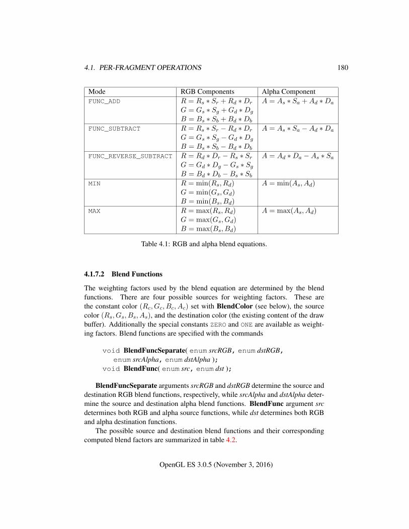
4.1. PER-FRAGMENT OPERATIONS 180
Mode RGB Components Alpha ComponentFUNC_ADD R = Rs ∗ Sr +Rd ∗Dr A = As ∗ Sa +Ad ∗Da
G = Gs ∗ Sg +Gd ∗Dg
B = Bs ∗ Sb +Bd ∗Db
FUNC_SUBTRACT R = Rs ∗ Sr −Rd ∗Dr A = As ∗ Sa −Ad ∗Da
G = Gs ∗ Sg −Gd ∗Dg
B = Bs ∗ Sb −Bd ∗Db
FUNC_REVERSE_SUBTRACT R = Rd ∗Dr −Rs ∗ Sr A = Ad ∗Da −As ∗ SaG = Gd ∗Dg −Gs ∗ SgB = Bd ∗Db −Bs ∗ Sb
MIN R = min(Rs, Rd) A = min(As, Ad)G = min(Gs, Gd)B = min(Bs, Bd)
MAX R = max(Rs, Rd) A = max(As, Ad)G = max(Gs, Gd)B = max(Bs, Bd)
Table 4.1: RGB and alpha blend equations.
4.1.7.2 Blend Functions
The weighting factors used by the blend equation are determined by the blendfunctions. There are four possible sources for weighting factors. These arethe constant color (Rc, Gc, Bc, Ac) set with BlendColor (see below), the sourcecolor (Rs, Gs, Bs, As), and the destination color (the existing content of the drawbuffer). Additionally the special constants ZERO and ONE are available as weight-ing factors. Blend functions are specified with the commands
void BlendFuncSeparate( enum srcRGB, enum dstRGB,enum srcAlpha, enum dstAlpha );
void BlendFunc( enum src, enum dst );
BlendFuncSeparate arguments srcRGB and dstRGB determine the source anddestination RGB blend functions, respectively, while srcAlpha and dstAlpha deter-mine the source and destination alpha blend functions. BlendFunc argument srcdetermines both RGB and alpha source functions, while dst determines both RGBand alpha destination functions.
The possible source and destination blend functions and their correspondingcomputed blend factors are summarized in table 4.2.
OpenGL ES 3.0.5 (November 3, 2016)
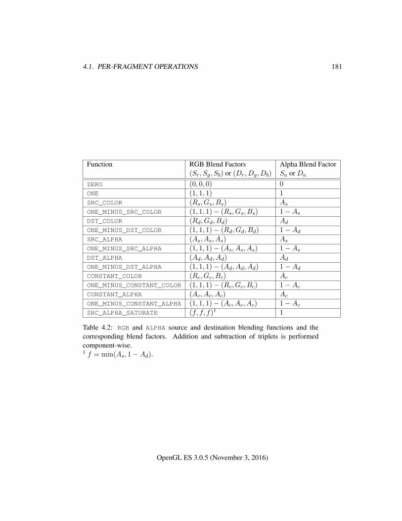
4.1. PER-FRAGMENT OPERATIONS 181
Function RGB Blend Factors Alpha Blend Factor(Sr, Sg, Sb) or (Dr, Dg, Db) Sa or Da
ZERO (0, 0, 0) 0
ONE (1, 1, 1) 1
SRC_COLOR (Rs, Gs, Bs) As
ONE_MINUS_SRC_COLOR (1, 1, 1)− (Rs, Gs, Bs) 1−As
DST_COLOR (Rd, Gd, Bd) Ad
ONE_MINUS_DST_COLOR (1, 1, 1)− (Rd, Gd, Bd) 1−Ad
SRC_ALPHA (As, As, As) As
ONE_MINUS_SRC_ALPHA (1, 1, 1)− (As, As, As) 1−As
DST_ALPHA (Ad, Ad, Ad) Ad
ONE_MINUS_DST_ALPHA (1, 1, 1)− (Ad, Ad, Ad) 1−Ad
CONSTANT_COLOR (Rc, Gc, Bc) Ac
ONE_MINUS_CONSTANT_COLOR (1, 1, 1)− (Rc, Gc, Bc) 1−Ac
CONSTANT_ALPHA (Ac, Ac, Ac) Ac
ONE_MINUS_CONSTANT_ALPHA (1, 1, 1)− (Ac, Ac, Ac) 1−Ac
SRC_ALPHA_SATURATE (f, f, f)1 1
Table 4.2: RGB and ALPHA source and destination blending functions and thecorresponding blend factors. Addition and subtraction of triplets is performedcomponent-wise.1 f = min(As, 1−Ad).
OpenGL ES 3.0.5 (November 3, 2016)
4.1. PER-FRAGMENT OPERATIONS 182
4.1.7.3 Blend Color
The constant color Cc to be used in blending is specified with the command
void BlendColor( float red, float green, float blue,float alpha );
The constant color can be used in both the source and destination blendingfunctions. If destination framebuffer components use an unsigned normalizedfixed-point representation, the constant color components are clamped to the range[0, 1] when computing the blend factors.
4.1.7.4 Blending State
The state required for blending is two integers for the RGB and alpha blend equa-tions, four integers indicating the source and destination RGB and alpha blendingfunctions, four floating-point values to store the RGBA constant blend color, and abit indicating whether blending is enabled or disabled.
The initial blend equations for RGB and alpha are both FUNC_ADD. The initialblending functions are ONE for the source RGB and alpha functions and ZERO
for the destination RGB and alpha functions. The initial constant blend color is(R,G,B,A) = (0, 0, 0, 0). Initially, blending is disabled.
Blending occurs once for each color buffer currently enabled for writing (sec-tion 4.2.1) using each buffer’s color for Cd. If a color buffer has no A value, thenAd is taken to be 1.
4.1.8 sRGB Conversion
If the value of FRAMEBUFFER_ATTACHMENT_COLOR_ENCODING for the frame-buffer attachment corresponding to the destination buffer is SRGB (see sec-tion 6.1.13), the R, G, and B values after blending are converted into the non-linearsRGB color space by computing
cs =
0.0, cl ≤ 0
12.92cl, 0 < cl < 0.0031308
1.055c0.41666l − 0.055, 0.0031308 ≤ cl < 1
1.0, cl ≥ 1
(4.1)
where cl is the R, G, or B element and cs is the result (effectively converted into ansRGB color space).
If FRAMEBUFFER_ATTACHMENT_COLOR_ENCODING is not SRGB, then
OpenGL ES 3.0.5 (November 3, 2016)
4.1. PER-FRAGMENT OPERATIONS 183
cs = cl.
The resulting cs values for R, G, and B, and the unmodified A form a newRGBA color value. If the color buffer is fixed-point, each component is clampedto the range [0, 1] and then converted to a fixed-point value using equation 2.3. Theresulting four values are sent to the subsequent dithering operation.
4.1.9 Dithering
Dithering selects between two representable color values or indices. A repre-sentable value is a value that has an exact representation in the color buffer. Dither-ing selects, for each color component, either the largest representable color value(for that particular color component) that is less than or equal to the incoming colorcomponent value, c, or the smallest representable color value that is greater than orequal to c. The selection may depend on the xw and yw coordinates of the pixel,as well as on the exact value of c. If one of the two values does not exist, then theselection defaults to the other value.
Many dithering selection algorithms are possible, but an individual selectionmust depend only on the incoming component value and the fragment’s x and ywindow coordinates. If dithering is disabled, then one of the two values above isselected, in an implementation-dependent manner that must not depend on the xwand yw coordinates of the pixel.
Dithering is enabled with Enable and disabled with Disable using the symbolicconstant DITHER. The state required is thus a single bit. Initially, dithering isenabled.
4.1.10 Additional Multisample Fragment Operations
If the value of SAMPLE_BUFFERS is one, the stencil test, depth test, blending, anddithering are performed for each pixel sample, rather than just once for each frag-ment. Failure of the stencil or depth test results in termination of the processing ofthat sample, rather than discarding of the fragment. All operations are performedon the color, depth, and stencil values stored in the multisample renderbuffer at-tachments if a framebuffer object is bound, or otherwise in the multisample bufferof the default framebuffer.
Stencil test, depth test, blending, and dithering operations are performed fora pixel sample only if that sample’s fragment coverage bit is a value of 1. If thecorresponding coverage bit is 0, no operations are performed for that sample.
If a framebuffer object is not bound, after all operations have been completedon the multisample buffer, the sample values for each color in the multisample
OpenGL ES 3.0.5 (November 3, 2016)
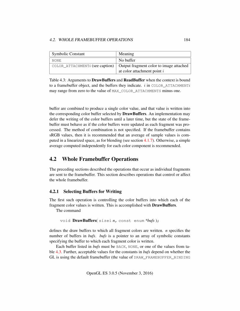
4.2. WHOLE FRAMEBUFFER OPERATIONS 184
Symbolic Constant MeaningNONE No bufferCOLOR_ATTACHMENTi (see caption) Output fragment color to image attached
at color attachment point i
Table 4.3: Arguments to DrawBuffers and ReadBuffer when the context is boundto a framebuffer object, and the buffers they indicate. i in COLOR_ATTACHMENTi
may range from zero to the value of MAX_COLOR_ATTACHMENTS minus one.
buffer are combined to produce a single color value, and that value is written intothe corresponding color buffer selected by DrawBuffers. An implementation maydefer the writing of the color buffers until a later time, but the state of the frame-buffer must behave as if the color buffers were updated as each fragment was pro-cessed. The method of combination is not specified. If the framebuffer containssRGB values, then it is recommended that an average of sample values is com-puted in a linearized space, as for blending (see section 4.1.7). Otherwise, a simpleaverage computed independently for each color component is recommended.
4.2 Whole Framebuffer Operations
The preceding sections described the operations that occur as individual fragmentsare sent to the framebuffer. This section describes operations that control or affectthe whole framebuffer.
4.2.1 Selecting Buffers for Writing
The first such operation is controlling the color buffers into which each of thefragment color values is written. This is accomplished with DrawBuffers.
The command
void DrawBuffers( sizei n, const enum *bufs );
defines the draw buffers to which all fragment colors are written. n specifies thenumber of buffers in bufs. bufs is a pointer to an array of symbolic constantsspecifying the buffer to which each fragment color is written.
Each buffer listed in bufs must be BACK, NONE, or one of the values from ta-ble 4.3. Further, acceptable values for the constants in bufs depend on whether theGL is using the default framebuffer (the value of DRAW_FRAMEBUFFER_BINDING
OpenGL ES 3.0.5 (November 3, 2016)
4.2. WHOLE FRAMEBUFFER OPERATIONS 185
is zero), or a framebuffer object (the value of DRAW_FRAMEBUFFER_BINDING isnon-zero). For more information about framebuffer objects, see section 4.4.
If the GL is bound to the default framebuffer, then n must be 1 and the constantmust be BACK or NONE. When draw buffer zero is BACK, color values are writteninto the sole buffer for single-buffered contexts, or into the back buffer for double-buffered contexts.
If the GL is bound to a draw framebuffer object, then each of the constantsmust be one of the values listed in table 4.3. Calling DrawBuffers with 0 as thevalue of n is equivalent to setting all the draw buffers to NONE.
In both cases, the draw buffers being defined correspond in order to the re-spective fragment colors. The draw buffer for fragment colors beyond n is set toNONE.
The maximum number of draw buffers is implementation-dependent. Thenumber of draw buffers supported can be queried by calling GetIntegerv withthe symbolic constant MAX_DRAW_BUFFERS.
If the GL is bound to a draw framebuffer object, the ith buffer listed in bufsmust be COLOR_ATTACHMENTi or NONE.
If an OpenGL ES Shading Language 1.00 fragment shader writes to gl_-
FragColor or gl_FragData, DrawBuffers specifies the draw buffer, if any, intowhich the single fragment color defined by gl_FragColor or gl_FragData[0]is written. If an OpenGL ES Shading Language 3.00 fragment shader writes a user-defined varying out variable, DrawBuffers specifies a set of draw buffers intowhich each of the multiple output colors defined by these variables are separatelywritten. If a fragment shader writes to none of gl_FragColor, gl_FragData,nor any user-defined output variables, the values of the fragment colors followingshader execution are undefined, and may differ for each fragment color. If some,but not all user-defined output variables are written, the values of fragment colorscorresponding to unwritten variables are similarly undefined.
The order of writes to user-defined output variables is undefined. If the sameimage is attached to multiple attachment points of a framebuffer object and differ-ent values are written to outputs bound to those attachments, the resulting value inthe attached image is undefined. Similarly undefined behavior results during anyother per-fragment operations where a multiply-attached image may be written toby more than one output, such as during blending.
Errors
An INVALID_VALUE error is generated if n is negative, or greater than thevalue of MAX_DRAW_BUFFERS.
OpenGL ES 3.0.5 (November 3, 2016)
4.2. WHOLE FRAMEBUFFER OPERATIONS 186
An INVALID_ENUM error is generated if any value in bufs is not one of thevalues in tables 4.3, BACK, or NONE.
An INVALID_OPERATION error is generated if the GL is bound to thedefault framebuffer and n is not 1, or *bufs is a value other than BACK orNONE.
An INVALID_OPERATION error is generated if the GL is bound to adraw framebuffer object and the ith argument is a value other than COLOR_-
ATTACHMENTi or NONE.
Indicating a buffer or buffers using DrawBuffers causes subsequent pixel colorvalue writes to affect the indicated buffers. If the GL is bound to a draw framebufferobject and a draw buffer selects an attachment that has no image attached, then thatfragment color is not written.
Specifying NONE as the draw buffer for a fragment color will inhibit that frag-ment color from being written.
The state required to handle color buffer selection for each framebuffer is aninteger for each supported fragment color. For the default framebuffer, in the initialstate the draw buffer for fragment color zero is BACK if there is a default frame-buffer associated with the context, otherwise NONE. For framebuffer objects, inthe initial state the draw buffer for fragment color zero is COLOR_ATTACHMENT0.For both the default framebuffer and framebuffer objects, the initial state of drawbuffers for fragment colors other than zero is NONE.
The draw buffer of the currently bound draw framebuffer selected for fragmentcolor i can be queried by calling GetIntegerv with pname set to DRAW_BUFFERi.
4.2.2 Fine Control of Buffer Updates
Writing of bits to each of the logical framebuffers after all per-fragment operationshave been performed may be masked. The command
void ColorMask( boolean r, boolean g, boolean b,boolean a );
controls writes to the active draw buffers.ColorMask is used to mask the writing of R, G, B and A values to all active
draw buffers r, g, b, and a indicate whether R, G, B, or A values, respectively, arewritten or not (a value of TRUE means that the corresponding value is written).
In the initial state, all color values are enabled for writing for all draw buffers.The depth buffer can be enabled or disabled for writing zw values using
void DepthMask( boolean mask );
OpenGL ES 3.0.5 (November 3, 2016)
4.2. WHOLE FRAMEBUFFER OPERATIONS 187
If mask is non-zero, the depth buffer is enabled for writing; otherwise, it is disabled.In the initial state, the depth buffer is enabled for writing.
The commands
void StencilMask( uint mask );void StencilMaskSeparate( enum face, uint mask );
control the writing of particular bits into the stencil planes.The least significant s bits of mask, where s is the number of bits in the stencil
buffer, specify an integer mask. Where a 1 appears in this mask, the correspondingbit in the stencil buffer is written; where a 0 appears, the bit is not written. The faceparameter of StencilMaskSeparate can be FRONT, BACK, or FRONT_AND_BACKand indicates whether the front or back stencil mask state is affected. StencilMasksets both front and back stencil mask state to identical values.
Fragments generated by front-facing primitives use the front mask and frag-ments generated by back-facing primitives use the back mask (see section 4.1.4).The clear operation always uses the front stencil write mask when clearing thestencil buffer.
The state required for the various masking operations is two integers for thefront and back stencil values, and a bit for depth values. A set of four bits is alsorequired indicating which color components of an RGBA value should be written.In the initial state, the integer masks are all ones, as are the bits controlling depthvalue and RGBA component writing.
4.2.2.1 Fine Control of Multisample Buffer Updates
When a framebuffer object is not bound and the value of SAMPLE_BUFFERS is one,ColorMask, DepthMask, and StencilMask or StencilMaskSeparate control themodification of values in the multisample buffer. The color mask has no effect onmodifications to the color buffers. If the color mask is entirely disabled, the colorsample values must still be combined (as described above) and the result used toreplace the color values of the buffers enabled by DrawBuffers.
4.2.3 Clearing the Buffers
The GL provides a means for setting portions of every pixel in a particular bufferto the same value. The argument to
void Clear( bitfield buf );
OpenGL ES 3.0.5 (November 3, 2016)
4.2. WHOLE FRAMEBUFFER OPERATIONS 188
is zero or the bitwise OR of one or more values indicating which buffers areto be cleared. The values are COLOR_BUFFER_BIT, DEPTH_BUFFER_BIT, andSTENCIL_BUFFER_BIT, indicating the buffers currently enabled for color writ-ing, the depth buffer, and the stencil buffer (see below), respectively. The value towhich each buffer is cleared depends on the setting of the clear value for that buffer.If buf is zero, no buffers are cleared. If buf contains any bits other than COLOR_-
BUFFER_BIT, DEPTH_BUFFER_BIT, or STENCIL_BUFFER_BIT, then the errorINVALID_VALUE is generated.
void ClearColor( float r, float g, float b, float a );
sets the clear value for fixed-point color buffers. The specified components arestored as floating-point values. Unsigned normalized fixed-point RGBA colorbuffers are cleared to color values derived by clamping each component of theclear color to the range [0, 1], then converting the (possibly sRGB converted and/ordithered) color to fixed-point using equations 2.3 or 2.4, respectively. The result ofclearing integer color buffers with Clear is undefined.
The command
void ClearDepthf( float d );
sets the depth value used when clearing the depth buffer. d is clamped to therange [0, 1]. When clearing a fixed-point depth buffer, d is converted to fixed-pointaccording to the rules for a window z value given in section 2.13.1. No conversionis applied when clearing a floating-point depth buffer.
The command
void ClearStencil( int s );
takes a single integer argument that is the value to which to clear the stencil buffer.When clearing a stencil buffer, s is masked to the number of bitplanes in the stencilbuffer.
When Clear is called, the only per-fragment operations that are applied (ifenabled) are the pixel ownership test, the scissor test, sRGB conversion (see sec-tion 4.1.8), and dithering. The masking operations described in section 4.2.2 arealso applied. If a buffer is not present, then a Clear directed at that buffer has noeffect.
The state required for clearing is a clear value for each of the color buffer,the depth buffer, and the stencil buffer. Initially, the RGBA color clear value is(0.0, 0.0, 0.0, 0.0), the depth buffer clear value is 1.0, and the stencil buffer clearindex is 0.
OpenGL ES 3.0.5 (November 3, 2016)
4.2. WHOLE FRAMEBUFFER OPERATIONS 189
Individual buffers of the currently bound draw framebuffer may be cleared withthe command
void ClearBuffer{if ui}v( enum buffer, int drawbuffer,const T *value );
where buffer and drawbuffer identify a buffer to clear, and value specifies the valueor values to clear it to.
If buffer is COLOR, a particular draw buffer DRAW_BUFFERi is specified bypassing i as the parameter drawbuffer, and value points to a four-element vec-tor specifying the R, G, B, and A color to clear that draw buffer to. The Clear-Bufferfv, ClearBufferiv, and ClearBufferuiv commands should be used to clearfixed- and floating-point, signed integer, and unsigned integer color buffers respec-tively. Clamping and conversion for fixed-point color buffers are performed in thesame fashion as Clear.
If buffer is DEPTH, drawbuffer must be zero, and value points to the single depthvalue to clear the depth buffer to. Clamping and type conversion for fixed-pointdepth buffers are performed in the same fashion as Clear. Only ClearBufferfvshould be used to clear depth buffers; neither ClearBufferiv nor ClearBufferuivaccept a buffer of DEPTH.
If buffer is STENCIL, drawbuffer must be zero, and value points to the sin-gle stencil value to clear the stencil buffer to. Masking and type conversion areperformed in the same fashion as Clear. Only ClearBufferiv should be used toclear stencil buffers; neither ClearBufferfv nor ClearBufferuiv accept a buffer ofSTENCIL.
The command
void ClearBufferfi( enum buffer, int drawbuffer,float depth, int stencil );
clears both depth and stencil buffers of the currently bound draw framebuffer.buffer must be DEPTH_STENCIL and drawbuffer must be zero. depth and sten-cil are the values to clear the depth and stencil buffers to, respectively. Clampingand type conversion of depth for fixed-point depth buffers is performed in the samefashion as Clear. Masking of stencil for stencil buffers is performed in the samefashion as Clear. ClearBufferfi is equivalent to clearing the depth and stencilbuffers separately, but may be faster when a buffer of internal format DEPTH_-STENCIL is being cleared.
The result of ClearBuffer is undefined if no conversion between the type ofthe specified value and the type of the buffer being cleared is defined (for example,
OpenGL ES 3.0.5 (November 3, 2016)
4.3. READING AND COPYING PIXELS 190
if ClearBufferiv is called for a fixed- or floating-point buffer, or if ClearBufferfvis called for a signed or unsigned integer buffer). This is not an error.
When ClearBuffer is called, the same per-fragment and masking operationsdefined for Clear are applied.
ClearBufferiv generates an INVALID_ENUM error if buffer is not COLOR orSTENCIL. ClearBufferuiv generates an INVALID_ENUM error if buffer is notCOLOR.
ClearBufferfv generates an INVALID_ENUM error if buffer is not COLOR orDEPTH. ClearBufferfi generates an INVALID_ENUM error if buffer is not DEPTH_-STENCIL.
ClearBuffer generates an INVALID_VALUE error if buffer is COLOR and draw-buffer is less than zero, or greater than the value of MAX_DRAW_BUFFERS minusone; or if buffer is DEPTH, STENCIL, or DEPTH_STENCIL and drawbuffer is notzero.
4.2.3.1 Clearing the Multisample Buffer
The color samples of the multisample buffer are cleared when one or more colorbuffers are cleared, as specified by the Clear mask bit COLOR_BUFFER_BIT andthe DrawBuffers mode. If the DrawBuffers mode is NONE, the color samples ofthe multisample buffer cannot be cleared using Clear.
If the Clear mask bits DEPTH_BUFFER_BIT or STENCIL_BUFFER_BIT areset, then the corresponding depth or stencil samples, respectively, are cleared.
The ClearBuffer commands also clear color, depth, or stencil samples of mul-tisample buffers corresponding to the specified buffer.
Masking and scissoring affect clearing the multisample buffer in the same wayas they affect clearing the corresponding color, depth, and stencil buffers.
4.3 Reading and Copying Pixels
Pixels may be read from the framebuffer using ReadPixels. BlitFramebuffer canbe used to copy a block of pixels from one portion of the framebuffer to another.Pixels may also be copied from client memory or the framebuffer to texture im-ages in the GL using the texture image specification commands, as described insections 3.8.3- 3.8.6.
4.3.1 Selecting Buffers for Reading
When reading pixels from a color buffer, the buffer selected for reading is termedthe read buffer, and is controlled with the command
OpenGL ES 3.0.5 (November 3, 2016)
4.3. READING AND COPYING PIXELS 191
void ReadBuffer( enum src );
If the GL is bound to the default framebuffer (see section 4.4), src must be BACKor NONE. BACK refers to the back buffer of a double-buffered context or the solebuffer of a single-buffered context. The initial value of the read framebuffer forthe default framebuffer is BACK if there is a default framebuffer associated with thecontext, otherwise it is NONE. An INVALID_OPERATION error is generated if srcis one of the values from table 4.3 (other than NONE) or if src is BACK and there isno default framebuffer associated with the context.
If the GL is bound to a read framebuffer object, src must be one of the valueslisted in table 4.3, including NONE. Specifying COLOR_ATTACHMENTi enables read-ing from the image attached to the framebuffer at that attachment point. The initialvalue of the read framebuffer for framebuffer objects is COLOR_ATTACHMENT0.An INVALID_OPERATION error is generated if src is BACK or if src is COLOR_-ATTACHMENTm where m is greater than or equal to the value of MAX_COLOR_-ATTACHMENTS.
An INVALID_ENUM error is generated if src is not BACK or one of the valuesfrom table 4.3.
The read buffer of the currently bound read framebuffer can be queried bycalling GetIntegerv with pname set to READ_BUFFER.
4.3.2 Reading Pixels
The method for reading pixels from the framebuffer and placing them in pixel packbuffer or client memory is diagrammed in figure 4.2. We describe the stages of thepixel reading process in the order in which they occur.
Initially, zero is bound for the PIXEL_PACK_BUFFER, indicating that imageread and query commands such as ReadPixels return pixel results into client mem-ory pointer parameters. However, if a non-zero buffer object is bound as the currentpixel pack buffer, then the pointer parameter is treated as an offset into the desig-nated buffer object.
Pixels are read using
void ReadPixels( int x, int y, sizei width, sizei height,enum format, enum type, void *data );
The arguments after x and y to ReadPixels are described in section 3.7.2. The pixelstorage modes that apply to ReadPixels and other commands that query images(see section 6.1) are summarized in table 4.4.
Only two combinations of format and type are accepted in most cases. Thefirst varies depending on the format of the currently bound rendering surface. For
OpenGL ES 3.0.5 (November 3, 2016)
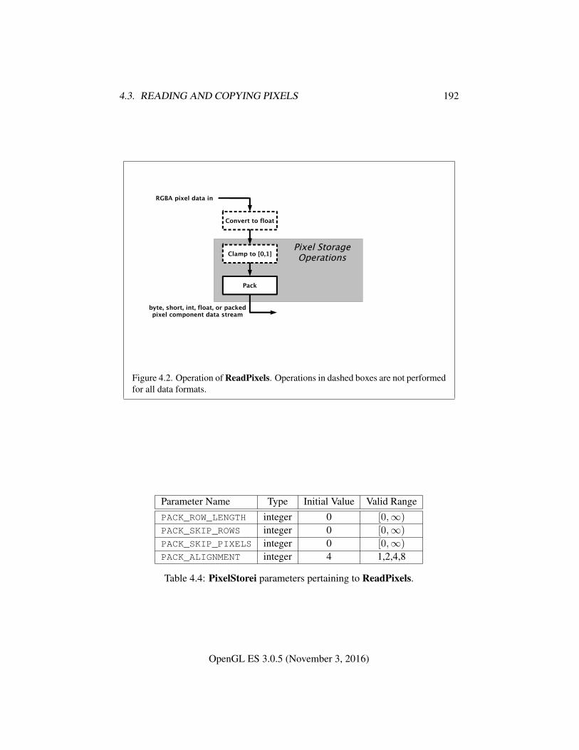
4.3. READING AND COPYING PIXELS 192
byte, short, int, float, or packedpixel component data stream
Clamp to [0,1]
Pack
Convert to float
RGBA pixel data in
Pixel StorageOperations
Figure 4.2. Operation of ReadPixels. Operations in dashed boxes are not performedfor all data formats.
Parameter Name Type Initial Value Valid RangePACK_ROW_LENGTH integer 0 [0,∞)
PACK_SKIP_ROWS integer 0 [0,∞)
PACK_SKIP_PIXELS integer 0 [0,∞)
PACK_ALIGNMENT integer 4 1,2,4,8
Table 4.4: PixelStorei parameters pertaining to ReadPixels.
OpenGL ES 3.0.5 (November 3, 2016)
4.3. READING AND COPYING PIXELS 193
normalized fixed-point rendering surfaces, the combination format RGBA and typeUNSIGNED_BYTE is accepted. For signed integer rendering surfaces, the combina-tion format RGBA_INTEGER and type INT is accepted. For unsigned integer ren-dering surfaces, the combination format RGBA_INTEGER and type UNSIGNED_INTis accepted.
The second is an implementation-chosen format from among those definedin table 3.2, excluding formats DEPTH_COMPONENT and DEPTH_STENCIL. Thevalues of format and type for this format may be determined by calling Get-Integerv with the symbolic constants IMPLEMENTATION_COLOR_READ_FORMATand IMPLEMENTATION_COLOR_READ_TYPE, respectively. GetIntegerv gen-erates an INVALID_OPERATION error in these cases if the object bound toREAD_FRAMEBUFFER_BINDING is not framebuffer complete (as defined in sec-tion 4.4.4.2), or if READ_BUFFER is NONE, or if the GL is using a framebuffer ob-ject (i.e. READ_FRAMEBUFFER_BINDING is non-zero) and the read buffer selectsan attachment that has no image attached. The implementation-chosen format mayvary depending on the format of the selected read buffer of the currently boundread framebuffer.
Additionally, when the internal format of the rendering surface is RGB10_A2,a third combination of format RGBA and type UNSIGNED_INT_2_10_10_10_REVis accepted.
ReadPixels generates an INVALID_OPERATION error if the combination offormat and type is unsupported.
ReadPixels generates an INVALID_OPERATION errorif READ_FRAMEBUFFER_BINDING (see section 4.4) is non-zero, the read frame-buffer is framebuffer complete, and the value of SAMPLE_BUFFERS for the readframebuffer is one.
ReadPixels generates an INVALID_FRAMEBUFFER_OPERATION error if theobject bound to READ_FRAMEBUFFER_BINDING is not framebuffer complete.
4.3.2.1 Obtaining Pixels from the Framebuffer
Values are obtained from the color buffer selected by the read buffer (see sec-tion 4.3.1).
ReadPixels generates an INVALID_OPERATION error if READ_BUFFER isNONE or if the GL is using a framebuffer object (i.e. READ_FRAMEBUFFER_-
BINDING is non-zero) and the read buffer selects an attachment that has no imageattached.
ReadPixels obtains values from the selected buffer from each pixel with lowerleft hand corner at (x+ i, y+ j) for 0 ≤ i < width and 0 ≤ j < height; this pixelis said to be the ith pixel in the jth row. If any of these pixels lies outside of the
OpenGL ES 3.0.5 (November 3, 2016)
4.3. READING AND COPYING PIXELS 194
window allocated to the current GL context, or outside of the image attached to thecurrently bound read framebuffer object, then the values obtained for those pixelsare undefined. When READ_FRAMEBUFFER_BINDING is zero, values are also un-defined for individual pixels that are not owned by the current context. Otherwise,ReadPixels obtains values from the selected buffer, regardless of how those valueswere placed there.
If format is one of RED, RG, RGB, or RGBA, then red, green, blue, and alphavalues are obtained from the selected buffer at each pixel location.
If format is an integer format and the color buffer is not an integer format; if thecolor buffer is an integer format and format is not an integer format; or if formatis an integer format and type is FLOAT, HALF_FLOAT, or UNSIGNED_INT_10F_-11F_11F_REV, the error INVALID_OPERATION occurs.
When READ_FRAMEBUFFER_BINDING is non-zero, the red, green, blue, andalpha values are obtained by first reading the internal component values of thecorresponding value in the image attached to the selected logical buffer. Internalcomponents are converted to an RGBA color by taking each R, G, B, and A com-ponent present according to the base internal format of the buffer (as shown intable 3.11). If G, B, or A values are not present in the internal format, they aretaken to be zero, zero, and one respectively.
4.3.2.2 Conversion of RGBA values
The R, G, B, and A values form a group of elements. For a normalized fixed-pointcolor buffer, each element is converted to floating-point using equation 2.1. For aninteger color buffer, the elements are unmodified.
4.3.2.3 Final Conversion
For a floating-point RGBA color, if type is not one of FLOAT, HALF_FLOAT, orUNSIGNED_INT_10F_11F_11F_REV, each component is first clamped to [0, 1].Then the appropriate conversion formula from table 4.5 is applied to the compo-nent.
In the special case of calling ReadPixels with type of UNSIGNED_INT_10F_-11F_11F_REV and format of RGB, conversion is performed as follows: the returneddata are packed into a series of uint values. The red, green, and blue componentsare converted to unsigned 11-bit floating-point, unsigned 11-bit floating-point, andunsigned 10-bit floating point as described in sections 2.1.3 and 2.1.4. The result-ing red 11 bits, green 11 bits, and blue 10 bits are then packed as the 1st, 2nd, and3rd components of the UNSIGNED_INT_10F_11F_11F_REV format as shown intable 3.8.
OpenGL ES 3.0.5 (November 3, 2016)
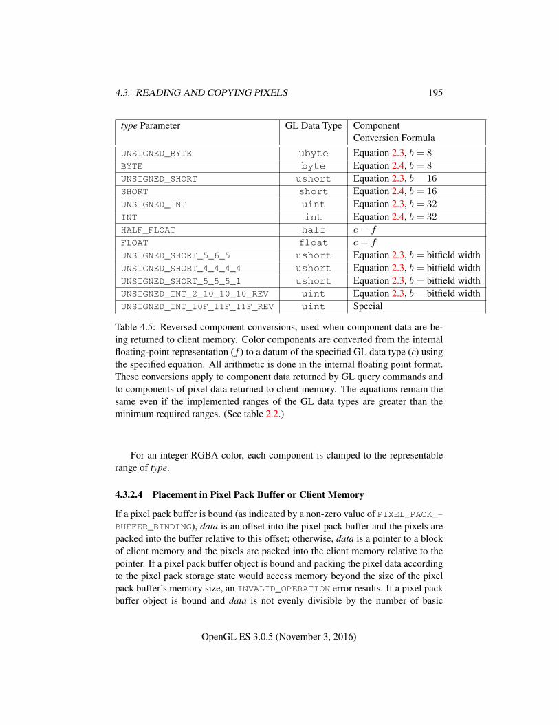
4.3. READING AND COPYING PIXELS 195
type Parameter GL Data Type ComponentConversion Formula
UNSIGNED_BYTE ubyte Equation 2.3, b = 8
BYTE byte Equation 2.4, b = 8
UNSIGNED_SHORT ushort Equation 2.3, b = 16
SHORT short Equation 2.4, b = 16
UNSIGNED_INT uint Equation 2.3, b = 32
INT int Equation 2.4, b = 32
HALF_FLOAT half c = f
FLOAT float c = f
UNSIGNED_SHORT_5_6_5 ushort Equation 2.3, b = bitfield widthUNSIGNED_SHORT_4_4_4_4 ushort Equation 2.3, b = bitfield widthUNSIGNED_SHORT_5_5_5_1 ushort Equation 2.3, b = bitfield widthUNSIGNED_INT_2_10_10_10_REV uint Equation 2.3, b = bitfield widthUNSIGNED_INT_10F_11F_11F_REV uint Special
Table 4.5: Reversed component conversions, used when component data are be-ing returned to client memory. Color components are converted from the internalfloating-point representation (f ) to a datum of the specified GL data type (c) usingthe specified equation. All arithmetic is done in the internal floating point format.These conversions apply to component data returned by GL query commands andto components of pixel data returned to client memory. The equations remain thesame even if the implemented ranges of the GL data types are greater than theminimum required ranges. (See table 2.2.)
For an integer RGBA color, each component is clamped to the representablerange of type.
4.3.2.4 Placement in Pixel Pack Buffer or Client Memory
If a pixel pack buffer is bound (as indicated by a non-zero value of PIXEL_PACK_-BUFFER_BINDING), data is an offset into the pixel pack buffer and the pixels arepacked into the buffer relative to this offset; otherwise, data is a pointer to a blockof client memory and the pixels are packed into the client memory relative to thepointer. If a pixel pack buffer object is bound and packing the pixel data accordingto the pixel pack storage state would access memory beyond the size of the pixelpack buffer’s memory size, an INVALID_OPERATION error results. If a pixel packbuffer object is bound and data is not evenly divisible by the number of basic
OpenGL ES 3.0.5 (November 3, 2016)
4.3. READING AND COPYING PIXELS 196
machine units needed to store in memory the corresponding GL data type fromtable 3.4 for the type parameter, an INVALID_OPERATION error results.
Groups of elements are placed in memory just as they are taken from memorywhen transferring pixel rectangles to the GL. That is, the ith group of the jth row(corresponding to the ith pixel in the jth row) is placed in memory just wherethe ith group of the jth row would be taken from when transferring pixels. SeeUnpacking under section 3.7.2.1. The only difference is that the storage modeparameters whose names begin with PACK_ are used instead of those whose namesbegin with UNPACK_. If the format is RED only the corresponding single elementis written. Likewise if the format is RG or RGB, only the corresponding two or threeelements are written. Otherwise all the elements of each group are written.
4.3.3 Copying Pixels
The command
void BlitFramebuffer( int srcX0, int srcY0, int srcX1,int srcY1, int dstX0, int dstY0, int dstX1, int dstY1,bitfield mask, enum filter );
transfers a rectangle of pixel values from one region of the read framebuffer toanother in the draw framebuffer. mask is zero or the bitwise OR of one or morevalues indicating which buffers are to be copied. The values are COLOR_BUFFER_-BIT, DEPTH_BUFFER_BIT, and STENCIL_BUFFER_BIT, which are described insection 4.2.3. The pixels corresponding to these buffers are copied from thesource rectangle bounded by the locations (srcX0, srcY 0) and (srcX1, srcY 1)to the destination rectangle bounded by the locations (dstX0, dstY 0) and(dstX1, dstY 1). Pixels have half-integer center coordinates. Only pixels whosecenters lie within the destination rectangle are written by BlitFramebuffer. Linearfilter sampling (see below) may result in pixels outside the source rectangle beingread.
If mask is zero, no buffers are copied. If mask contains any bits other thanCOLOR_BUFFER_BIT, DEPTH_BUFFER_BIT, or STENCIL_BUFFER_BIT, then theerror INVALID_VALUE is generated.
When the color buffer is transferred, values are taken from the read buffer of theread framebuffer and written to each of the draw buffers of the draw framebuffer.
The actual region taken from the read framebuffer is limited to the intersectionof the source buffers being transferred, which may include the color buffer selectedby the read buffer, the depth buffer, and/or the stencil buffer depending on mask.The actual region written to the draw framebuffer is limited to the intersection of
OpenGL ES 3.0.5 (November 3, 2016)
4.3. READING AND COPYING PIXELS 197
the destination buffers being written, which may include multiple draw buffers,the depth buffer, and/or the stencil buffer depending on mask. Whether or not thesource or destination regions are altered due to these limits, the scaling and offsetapplied to pixels being transferred is performed as though no such limits werepresent.
If the source and destination rectangle dimensions do not match, the source im-age is stretched to fit the destination rectangle. filter must be LINEAR or NEAREST,and specifies the method of interpolation to be applied if the image is stretched.LINEAR filtering is allowed only for the color buffer; if mask includes DEPTH_-BUFFER_BIT or STENCIL_BUFFER_BIT, and filter is not NEAREST, no copy isperformed and an INVALID_OPERATION error is generated. If the source and des-tination dimensions are identical, no filtering is applied. If either the source or des-tination rectangle specifies a negative width or height (X1 < X0 or Y 1 < Y 0), theimage is reversed in the corresponding direction. If both the source and destinationrectangles specify a negative width or height for the same direction, no reversalis performed. If a linear filter is selected and the rules of LINEAR sampling (seesection 3.8.10.2) would require sampling outside the bounds of a source buffer, itis as though CLAMP_TO_EDGE texture sampling were being performed. If a linearfilter is selected and sampling would be required outside the bounds of the spec-ified source region, but within the bounds of a source buffer, the implementationmay choose to clamp while sampling or not.
If the source and destination buffers are identical, an INVALID_OPERATION
error is generated. Different mipmap levels of a texture, different layers of a three-dimensional texture or two-dimensional array texture, and different faces of a cubemap texture do not constitute identical buffers.
When values are taken from the read buffer, if the value of FRAMEBUFFER_-ATTACHMENT_COLOR_ENCODING for the framebuffer attachment corresponding tothe read buffer is SRGB (see section 6.1.13), the red, green, and blue componentsare converted from the non-linear sRGB color space according to equation 3.26.
When values are written to the draw buffers, blit operations bypass the frag-ment pipeline. The only fragment operations which affect a blit are the pixel own-ership test, the scissor test and sRGB conversion (see section 4.1.8). Color, depth,and stencil masks (see section 4.2.2) are ignored.
If a buffer is specified in mask and does not exist in both the read and drawframebuffers, the corresponding bit is silently ignored.
If the color formats of the read and draw buffers do not match, and mask in-cludes COLOR_BUFFER_BIT, pixel groups are converted to match the destinationformat. However, colors are clamped only if all draw color buffers have fixed-point components. Format conversion is not supported for all data types, and anINVALID_OPERATION error is generated under any of the following conditions:
OpenGL ES 3.0.5 (November 3, 2016)
4.3. READING AND COPYING PIXELS 198
• The read buffer contains fixed-point values and any draw buffer does notcontain fixed-point values.
• The read buffer contains unsigned integer values and any draw buffer doesnot contain unsigned integer values.
• The read buffer contains signed integer values and any draw buffer does notcontain signed integer values.
Calling BlitFramebuffer will result in an INVALID_FRAMEBUFFER_-
OPERATION error if the objects bound to DRAW_FRAMEBUFFER_BINDING andREAD_FRAMEBUFFER_BINDING are not framebuffer complete (section 4.4.4.2).
Calling BlitFramebuffer will result in an INVALID_OPERATION error if maskincludes DEPTH_BUFFER_BIT or STENCIL_BUFFER_BIT, and the source anddestination depth and stencil buffer formats do not match.
Calling BlitFramebuffer will result in an INVALID_OPERATION error if filteris LINEAR and read buffer contains integer data.
If the value of SAMPLE_BUFFERS for the read framebuffer is one and the valueof SAMPLE_BUFFERS for the draw framebuffer is zero, the samples correspondingto each pixel location in the source are converted to a single sample before beingwritten to the destination. The filter parameter is ignored. If the source formatsare integer types or stencil values, a single sample’s value is selected for eachpixel. If the source formats are floating-point or normalized types, the samplevalues for each pixel are resolved in an implementation-dependent manner. If thesource formats are depth values, sample values are resolved in an implementation-dependent manner where the result will be between the minimum and maximumdepth values in the pixel.
If SAMPLE_BUFFERS for the read framebuffer is one, no copy is performedand an INVALID_OPERATION error is generated if the formats of the read anddraw framebuffers are not identical or if the source and destination rectangles arenot defined with the same (X0, Y 0) and (X1, Y 1) bounds.
If SAMPLE_BUFFERS for the draw framebuffer is greater than zero, anINVALID_OPERATION error is generated.
4.3.4 Pixel Draw/Read State
The state required for pixel operations consists of the parameters that are set withPixelStorei. This state has been summarized in table 3.1. Additional state includesan integer indicating the current setting of ReadBuffer. State set with PixelStoreiis GL client state.
OpenGL ES 3.0.5 (November 3, 2016)
4.4. FRAMEBUFFER OBJECTS 199
4.4 Framebuffer Objects
As described in chapter 1 and section 2.1, the GL renders into (and reads valuesfrom) a framebuffer. The GL defines two classes of framebuffers: window system-provided and application-created.
Initially, the GL uses the default framebuffer. The storage, dimensions, allo-cation, and format of the images attached to this framebuffer are managed entirelyby the window system. Consequently, the state of the default framebuffer, includ-ing its images, can not be changed by the GL, nor can the default framebuffer bedeleted by the GL.
The routines described in the following sections, however, can be used to cre-ate, destroy, and modify the state and attachments of framebuffer objects.
Framebuffer objects encapsulate the state of a framebuffer in a similar mannerto the way texture objects encapsulate the state of a texture. In particular, a frame-buffer object encapsulates state necessary to describe a collection of color, depth,and stencil logical buffers (other types of buffers are not allowed). For each logicalbuffer, a framebuffer-attachable image can be attached to the framebuffer to storethe rendered output for that logical buffer. Examples of framebuffer-attachable im-ages include texture images and renderbuffer images. Renderbuffers are describedfurther in section 4.4.2.1
By allowing the images of a renderbuffer to be attached to a framebuffer, theGL provides a mechanism to support off-screen rendering. Further, by allowing theimages of a texture to be attached to a framebuffer, the GL provides a mechanismto support render to texture.
4.4.1 Binding and Managing Framebuffer Objects
The default framebuffer for rendering and readback operations is provided by thewindow system. In addition, named framebuffer objects can be created and oper-ated upon. The name space for framebuffer objects is the unsigned integers, withzero reserved by the GL for the default framebuffer.
The command
void GenFramebuffers( sizei n, uint *framebuffers );
returns n previously unused framebuffer object names in ids. These names aremarked as used, for the purposes of GenFramebuffers only, but they do not ac-quire state and type until they are first bound.
A framebuffer object is created by binding an unused name to DRAW_-
FRAMEBUFFER or READ_FRAMEBUFFER. The binding is effected by calling
OpenGL ES 3.0.5 (November 3, 2016)
4.4. FRAMEBUFFER OBJECTS 200
void BindFramebuffer( enum target, uint framebuffer );
with target set to the desired framebuffer target and framebuffer set to the frame-buffer object name. The resulting framebuffer object is a new state vector, com-prising all the state and with the same initial values listed in table 6.13, as wellas one set of the state values listed in table 6.14 for each attachment point of theframebuffer, with the same initial values. There are the values of MAX_COLOR_-ATTACHMENTS color attachment points, plus one set each for the depth and stencilattachment points.
BindFramebuffer may also be used to bind an existing framebuffer objectto DRAW_FRAMEBUFFER and/or READ_FRAMEBUFFER. If the bind is successful nochange is made to the state of the bound framebuffer object, and any previousbinding to target is broken.
If a framebuffer object is bound to DRAW_FRAMEBUFFER or READ_-
FRAMEBUFFER, it becomes the target for rendering or readback operations, respec-tively, until it is deleted or another framebuffer is bound to the corresponding bindpoint. Calling BindFramebuffer with target set to FRAMEBUFFER binds frame-buffer to both the draw and read targets.
While a framebuffer object is bound, GL operations on the target to which itis bound affect the images attached to the bound framebuffer object, and queriesof the target to which it is bound return state from the bound object. Queries ofthe values specified in tables 6.35 and 6.13 are derived from the framebuffer objectbound to DRAW_FRAMEBUFFER, with the exception of those marked as propertiesof the read framebuffer, which are derived from the framebuffer object bound toREAD_FRAMEBUFFER.
The initial state of DRAW_FRAMEBUFFER and READ_FRAMEBUFFER refers tothe default framebuffer. In order that access to the default framebuffer is not lost,it is treated as a framebuffer object with the name of zero. The default framebufferis therefore rendered to and read from while zero is bound to the correspondingtargets. On some implementations, the properties of the default framebuffer canchange over time (e.g., in response to window system events such as attaching thecontext to a new window system drawable.)
Framebuffer objects (those with a non-zero name) differ from the defaultframebuffer in a few important ways. First and foremost, unlike the default frame-buffer, framebuffer objects have modifiable attachment points for each logicalbuffer in the framebuffer. Framebuffer-attachable images can be attached to and de-tached from these attachment points, which are described further in section 4.4.2.Also, the size and format of the images attached to framebuffer objects are con-trolled entirely within the GL interface, and are not affected by window systemevents, such as pixel format selection, window resizes, and display mode changes.
OpenGL ES 3.0.5 (November 3, 2016)
4.4. FRAMEBUFFER OBJECTS 201
Additionally, when rendering to or reading from an application created-framebuffer object,
• The pixel ownership test always succeeds. In other words, framebuffer ob-jects own all of their pixels.
• There are no visible color buffer bitplanes. This means there is no colorbuffer corresponding to the back or front color bitplanes.
• The only color buffer bitplanes are the ones defined by the frame-buffer attachment points named COLOR_ATTACHMENT0 through COLOR_-
ATTACHMENTn. Each COLOR_ATTACHMENTi adheres to COLOR_-
ATTACHMENTi = COLOR_ATTACHMENT0 + i2.
• The only depth buffer bitplanes are the ones defined by the framebuffer at-tachment point DEPTH_ATTACHMENT.
• The only stencil buffer bitplanes are the ones defined by the framebufferattachment point STENCIL_ATTACHMENT.
• If the attachment sizes are not all identical, the results of rendering aredefined only within the largest area that can fit in all of the attachments.This area is defined as the intersection of rectangles having a lower left of(0, 0) and an upper right of (width, height) for each attachment. Contentsof attachments outside this area are undefined after execution of a renderingcommand (as defined in section 2.6).
If there are no attachments, rendering will be limited to a rectangle having alower left of (0, 0) and an upper right of (width, height), where width andheight are the framebuffer object’s default width and height.
Framebuffer objects are deleted by calling
void DeleteFramebuffers( sizei n, constuint *framebuffers );
framebuffers contains n names of framebuffer objects to be deleted. After a frame-buffer object is deleted, it has no attachments, and its name is again unused.
2 The header files define tokens COLOR_ATTACHMENTi for i in the range [0, 31]. Mostimplementations support fewer than 32 color attachments, and it is an INVALID_OPERATIONerror to pass an unsupported attachment name to a command accepting color attachment names.
OpenGL ES 3.0.5 (November 3, 2016)
4.4. FRAMEBUFFER OBJECTS 202
If a framebuffer that is currently bound to one or more of the targets DRAW_-
FRAMEBUFFER or READ_FRAMEBUFFER is deleted, it is as though BindFrame-buffer had been executed with the corresponding target and framebuffer zero. Un-used names in framebuffers that have been marked as used for the purposes ofGenFramebuffers are marked as unused again. Unused names in framebuffers aresilently ignored, as is the value zero.
The names bound to the draw and read framebuffer bindings can be queried bycalling GetIntegerv with the symbolic constants DRAW_FRAMEBUFFER_BINDINGand READ_FRAMEBUFFER_BINDING, respectively. FRAMEBUFFER_BINDING isequivalent to DRAW_FRAMEBUFFER_BINDING.
4.4.2 Attaching Images to Framebuffer Objects
Framebuffer-attachable images may be attached to, and detached from, framebufferobjects. In contrast, the image attachments of the default framebuffer may not bechanged by the GL.
A single framebuffer-attachable image may be attached to multiple framebufferobjects, potentially avoiding some data copies, and possibly decreasing memoryconsumption.
For each logical buffer, a framebuffer object stores a set of state which definesthe logical buffer’s attachment point. The attachment point state contains enoughinformation to identify the single image attached to the attachment point, or toindicate that no image is attached. The per-logical buffer attachment point state islisted in table 6.14.
There are several types of framebuffer-attachable images:
• The image of a renderbuffer object, which is always two-dimensional.
• A single level of a two-dimensional texture.
• A single face of a cube map texture level, which is treated as a two-dimensional image.
• A single layer of a two-dimensional array texture or three-dimensional tex-ture, which is treated as a two-dimensional image.
4.4.2.1 Renderbuffer Objects
A renderbuffer is a data storage object containing a single image of a renderableinternal format. The GL provides the methods described below to allocate anddelete renderbuffers and renderbuffer images, and to attach a renderbuffer’s image
OpenGL ES 3.0.5 (November 3, 2016)
4.4. FRAMEBUFFER OBJECTS 203
to a framebuffer object. The name space for renderbuffer objects is the unsignedintegers, with zero reserved for the GL.
The command
void GenRenderbuffers( sizei n, uint *renderbuffers );
returns n previously unused renderbuffer object names in renderbuffers. Thesenames are marked as used, for the purposes of GenRenderbuffers only, but theydo not acquire renderbuffer state until they are first bound.
A renderbuffer object is created by binding an unused name toRENDERBUFFER. The binding is effected by calling
void BindRenderbuffer( enum target, uint renderbuffer );
with target set to RENDERBUFFER and renderbuffer set to the renderbuffer objectname. If renderbuffer is not zero, then the resulting renderbuffer object is a newstate vector, initialized with a zero-sized memory buffer, and comprising all thestate and with the same initial values listed in table 6.15. Any previous binding totarget is broken.
BindRenderbuffer may also be used to bind an existing renderbuffer object.If the bind is successful, no change is made to the state of the newly bound render-buffer object, and any previous binding to target is broken.
While a renderbuffer object is bound, GL operations on the target to which itis bound affect the bound renderbuffer object, and queries of the target to which arenderbuffer object is bound return state from the bound object.
The name zero is reserved. A renderbuffer object cannot be created with thename zero. If renderbuffer is zero, then any previous binding to target is brokenand the target binding is restored to the initial state.
In the initial state, the reserved name zero is bound to RENDERBUFFER. There isno renderbuffer object corresponding to the name zero, so client attempts to modifyor query renderbuffer state for the target RENDERBUFFER while zero is bound willgenerate GL errors, as described in section 6.1.14.
The current RENDERBUFFER binding can be determined by calling GetInte-gerv with the symbolic constant RENDERBUFFER_BINDING.
Renderbuffer objects are deleted by calling
void DeleteRenderbuffers( sizei n, constuint *renderbuffers );
where renderbuffers contains n names of renderbuffer objects to be deleted. Aftera renderbuffer object is deleted, it has no contents, and its name is again unused. If
OpenGL ES 3.0.5 (November 3, 2016)
4.4. FRAMEBUFFER OBJECTS 204
a renderbuffer that is currently bound to RENDERBUFFER is deleted, it is as thoughBindRenderbuffer had been executed with the target RENDERBUFFER and nameof zero. Additionally, special care must be taken when deleting a renderbuffer if theimage of the renderbuffer is attached to a framebuffer object (see section 4.4.2.3).Unused names in renderbuffers that have been marked as used for the purposes ofGenRenderbuffers are marked as unused again. Unused names in renderbuffersare silently ignored, as is the value zero.
The command
void RenderbufferStorageMultisample( enum target,sizei samples, enum internalformat, sizei width,sizei height );
establishes the data storage, format, dimensions, and number of samples of a ren-derbuffer object’s image. target must be RENDERBUFFER. internalformat mustbe a sized internal format that is color-renderable, depth-renderable, or stencil-renderable (as defined in section 4.4.4). width and height are the dimensions inpixels of the renderbuffer. If either width or height is greater than the value ofMAX_RENDERBUFFER_SIZE, then the error INVALID_VALUE is generated. If in-ternalformat is a signed or unsigned integer format and samples is greater thanzero, then the error INVALID_OPERATION is generated. If samples is greaterthan the maximum number of samples supported for internalformat, then the errorINVALID_OPERATION is generated (see GetInternalformativ in section 6.1.15).If the GL is unable to create a data store of the requested size, the error OUT_OF_-MEMORY is generated.
Upon success, RenderbufferStorageMultisample deletes any existing datastore for the renderbuffer image and the contents of the data store after call-ing RenderbufferStorageMultisample are undefined. RENDERBUFFER_WIDTH
is set to width, RENDERBUFFER_HEIGHT is set to height, and RENDERBUFFER_-
INTERNAL_FORMAT is set to internalformat.If samples is zero, then RENDERBUFFER_SAMPLES is set to zero. Otherwise
samples represents a request for a desired minimum number of samples. Sincedifferent implementations may support different sample counts for multisamplerendering, the actual number of samples allocated for the renderbuffer image isimplementation-dependent. However, the resulting value for RENDERBUFFER_-SAMPLES is guaranteed to be greater than or equal to samples and no more than thenext larger sample count supported by the implementation.
A GL implementation may vary its allocation of internal component resolutionbased on any RenderbufferStorageMultisample parameter (except target), butthe allocation and chosen internal format must not be a function of any other stateand cannot be changed once they are established.
OpenGL ES 3.0.5 (November 3, 2016)
4.4. FRAMEBUFFER OBJECTS 205
The command
void RenderbufferStorage( enum target, enum internalformat,sizei width, sizei height );
is equivalent to calling RenderbufferStorageMultisample with samples equal tozero.
4.4.2.2 Required Renderbuffer Formats
Implementations are required to support the same internal formats for renderbuffersas the required formats for textures enumerated in section 3.8.3.1, with the excep-tion of the color formats labelled “texture-only”. Requesting one of these internalformats for a renderbuffer will allocate at least the internal component sizes andexactly the component types shown for that format in tables 3.13 - 3.14.
Implementations are also required to support STENCIL_INDEX8. Requestingthis internal format for a renderbuffer will allocate at least 8 stencil bit planes.
Implementations must support creation of renderbuffers in these required for-mats with up to the value of MAX_SAMPLES multisamples, with the exception ofsigned and unsigned integer formats.
4.4.2.3 Attaching Renderbuffer Images to a Framebuffer
A renderbuffer can be attached as one of the logical buffers of the currently boundframebuffer object by calling
void FramebufferRenderbuffer( enum target,enum attachment, enum renderbuffertarget,uint renderbuffer );
target must be DRAW_FRAMEBUFFER, READ_FRAMEBUFFER, or FRAMEBUFFER.FRAMEBUFFER is equivalent to DRAW_FRAMEBUFFER.
attachment must be set to one of the attachment points of the framebuffer listedin table 4.6.
renderbuffertarget must be RENDERBUFFER and renderbuffer is zero or thename of a renderbuffer object of type renderbuffertarget to be attached tothe framebuffer. If renderbuffer is zero, then the value of renderbuffertarget isignored.
If renderbuffer is not zero and if FramebufferRenderbuffer is successful,then the renderbuffer named renderbuffer will be used as the logical buffer iden-tified by attachment of the framebuffer currently bound to target. The value of
OpenGL ES 3.0.5 (November 3, 2016)
4.4. FRAMEBUFFER OBJECTS 206
FRAMEBUFFER_ATTACHMENT_OBJECT_TYPE for the specified attachment point isset to RENDERBUFFER and the value of FRAMEBUFFER_ATTACHMENT_OBJECT_-NAME is set to renderbuffer. All other state values of the attachment point specifiedby attachment are set to their default values listed in table 6.14. No change is madeto the state of the renderbuffer object and any previous attachment to the attach-ment logical buffer of the framebuffer object bound to framebuffer target is broken.If the attachment is not successful, then no change is made to the state of either therenderbuffer object or the framebuffer object.
Calling FramebufferRenderbuffer with the renderbuffer name zero will de-tach the image, if any, identified by attachment, in the framebuffer currently boundto target. All state values of the attachment point specified by attachment in theobject bound to target are set to their default values listed in table 6.14.
Setting attachment to the value DEPTH_STENCIL_ATTACHMENT is a specialcase causing both the depth and stencil attachments of the framebuffer object to beset to renderbuffer, which should have base internal format DEPTH_STENCIL.
If a renderbuffer object is deleted while its image is attached to one or more at-tachment points in a currently bound framebuffer object, then it is as if Framebuf-ferRenderbuffer had been called, with a renderbuffer of zero, for each attachmentpoint to which this image was attached in that framebuffer object. In other words,the renderbuffer image is first detached from all attachment points in that frame-buffer object. Note that the renderbuffer image is specifically not detached fromany non-bound framebuffers. Detaching the image from any non-bound frame-buffers is the responsibility of the application.
Name of attachmentCOLOR_ATTACHMENTi (see caption)DEPTH_ATTACHMENT
STENCIL_ATTACHMENT
DEPTH_STENCIL_ATTACHMENT
Table 4.6: Framebuffer attachment points. i in COLOR_ATTACHMENTi may rangefrom zero to the value of MAX_COLOR_ATTACHMENTS minus one.
Errors
An INVALID_ENUM error is generated if target is not DRAW_-
FRAMEBUFFER, READ_FRAMEBUFFER, or FRAMEBUFFER.An INVALID_OPERATION error is generated if attachment is COLOR_-
OpenGL ES 3.0.5 (November 3, 2016)
4.4. FRAMEBUFFER OBJECTS 207
ATTACHMENTmwherem is greater than or equal to the value of MAX_COLOR_-ATTACHMENTS.
An INVALID_ENUM error is generated if attachment is not one of the at-tachments in table 4.6, and attachment is not COLOR_ATTACHMENTm wherem is greater than or equal to the value of MAX_COLOR_ATTACHMENTS.
An INVALID_ENUM error is generated if renderbuffertarget is notRENDERBUFFER.
An INVALID_OPERATION error is generated if renderbuffer is not zero orthe name of an existing renderbuffer object of type renderbuffertarget.
An INVALID_OPERATION error is generated if zero is bound to target.
4.4.2.4 Attaching Texture Images to a Framebuffer
The GL supports copying the rendered contents of the framebuffer into the imagesof a texture object through the use of the routines CopyTexImage* and CopyTex-SubImage*. Additionally, the GL supports rendering directly into the images of atexture object.
To render directly into a texture image, a specified image from a two-dimensional or cube map texture object can be attached as one of the logical buffersof a framebuffer object by calling:
void FramebufferTexture2D( enum target, enum attachment,enum textarget, uint texture, int level );
The framebuffer object is that which is bound to target.target must be DRAW_FRAMEBUFFER, READ_FRAMEBUFFER, or
FRAMEBUFFER. FRAMEBUFFER is equivalent to DRAW_FRAMEBUFFER.attachment must be one of the attachment points of the framebuffer listed in
table 4.6.If texture is not zero, then texture must either name an existing two-dimensional
texture object and textarget must be TEXTURE_2D, or texture must name an existingcube map texture and textarget must be one of the cube map face targets fromtable 3.21.
level specifies the mipmap level of the texture image to be attached to theframebuffer.
If textarget is one of the cube map face targets from table 3.21, then level mustbe greater than or equal to zero and less than or equal to log2 of the value of MAX_-CUBE_MAP_TEXTURE_SIZE. If textarget is TEXTURE_2D, level must be greaterthan or equal to zero and no larger than log2 of the value of MAX_TEXTURE_SIZE.
OpenGL ES 3.0.5 (November 3, 2016)
4.4. FRAMEBUFFER OBJECTS 208
Errors
An INVALID_ENUM error is generated if target is not DRAW_-
FRAMEBUFFER, READ_FRAMEBUFFER, or FRAMEBUFFER.An INVALID_OPERATION error is generated if attachment is COLOR_-
ATTACHMENTmwherem is greater than or equal to the value of MAX_COLOR_-ATTACHMENTS.
An INVALID_ENUM error is generated if attachment is not one of the at-tachments in table 4.6, and attachment is not COLOR_ATTACHMENTm wherem is greater than or equal to the value of MAX_COLOR_ATTACHMENTS.
An INVALID_OPERATION error is generated if zero is bound to target.An INVALID_VALUE error is generated if texture is not zero and level is
not a supported texture level for textarget, as described above.An INVALID_VALUE error is generated if texture is not zero and layer is
larger than the value of MAX_3D_TEXTURE_SIZE minus one.An INVALID_OPERATION error is generated if texture is not zero and tex-
target is not one of TEXTURE_2D, TEXTURE_2D_MULTISAMPLE, or one of thecube map face targets from table 3.21.
An INVALID_OPERATION error is generated if texture is not zero, anddoes not name an existing texture object of type matching textarget, as de-scribed above.
An INVALID_OPERATION error is generated if texture is the name of abuffer texture.
The command
void FramebufferTextureLayer( enum target,enum attachment, uint texture, int level, int layer );
operates similarly to FramebufferTexture2D, except that it attaches a single layerof a three-dimensional texture or two-dimensional array texture level.
layer specifies the layer of a two-dimensional image within texture. AnINVALID_VALUE error is generated if layer is larger than the value of MAX_-3D_TEXTURE_SIZE minus one (for three-dimensional textures) or larger than thevalue of MAX_ARRAY_TEXTURE_LAYERS minus one (for two-dimensional arraytextures). The error INVALID_VALUE is generated if texture is non-zero and layeris negative.
If texture is a three-dimensional texture, then level must be greater than or equalto zero and less than or equal to log2 of the value of MAX_3D_TEXTURE_SIZE. Iftexture is a two-dimensional array texture, then level must be greater than or equal
OpenGL ES 3.0.5 (November 3, 2016)
4.4. FRAMEBUFFER OBJECTS 209
to zero and no larger than log2 of the value of MAX_TEXTURE_SIZE. Otherwise,an INVALID_VALUE error is generated.
The error INVALID_OPERATION is generated if texture is non-zero and is notthe name of a three-dimensional texture or two-dimensional array texture. UnlikeFramebufferTexture2D, no textarget parameter is accepted.
If texture is non-zero and the command does not result in an error, the frame-buffer attachment state corresponding to attachment is updated as in Framebuffer-Texture2D, except that the value of FRAMEBUFFER_ATTACHMENT_TEXTURE_-LAYER is set to layer.
Effects of Attaching a Texture Image
The remaining comments in this section apply to all forms of Framebuffer-Texture*.
If texture is zero, any image or array of images attached to the attachment pointnamed by attachment is detached. Any additional parameters (level, textarget,and/or layer) are ignored when texture is zero. All state values of the attachmentpoint specified by attachment are set to their default values listed in table 6.14.
If texture is not zero, and if FramebufferTexture* is successful, then the spec-ified texture image will be used as the logical buffer identified by attachment of theframebuffer currently bound to target. State values of the specified attachmentpoint are set as follows:
• The value of FRAMEBUFFER_ATTACHMENT_OBJECT_TYPE is set toTEXTURE.
• The value of FRAMEBUFFER_ATTACHMENT_OBJECT_NAME is set to texture.
• The value of FRAMEBUFFER_ATTACHMENT_TEXTURE_LEVEL is set to level.
• If FramebufferTexture2D is called and texture is a cube map texture, thenthe value of FRAMEBUFFER_ATTACHMENT_TEXTURE_CUBE_MAP_FACE isset to textarget; otherwise it is set tothe default (NONE).
• If FramebufferTextureLayer is called, then the value of FRAMEBUFFER_-ATTACHMENT_TEXTURE_LAYER is set to layer; otherwise it is set to zero.
All other state values of the attachment point specified by attachment are setto their default values listed in table 6.14. No change is made to the state of thetexture object, and any previous attachment to the attachment logical buffer of theframebuffer object bound to framebuffer target is broken. If the attachment is not
OpenGL ES 3.0.5 (November 3, 2016)
4.4. FRAMEBUFFER OBJECTS 210
successful, then no change is made to the state of either the texture object or theframebuffer object.
Setting attachment to the value DEPTH_STENCIL_ATTACHMENT is a specialcase causing both the depth and stencil attachments of the framebuffer object tobe set to texture. texture must have base internal format DEPTH_STENCIL, or thedepth and stencil framebuffer attachments will be incomplete (see section 4.4.4.1).
If a texture object is deleted while its image is attached to one or more attach-ment points in a currently bound framebuffer, then it is as if FramebufferTexture*had been called, with a texture of zero, for each attachment point to which this im-age was attached in that framebuffer. In other words, this texture image is firstdetached from all attachment points in a currently bound framebuffer. Note thatthe texture image is specifically not detached from any other framebuffer objects.Detaching the texture image from any other framebuffer objects is the responsibil-ity of the application.
4.4.3 Feedback Loops Between Textures and the Framebuffer
A feedback loop may exist when a texture object is used as both the source anddestination of a GL operation. When a feedback loop exists, undefined behaviorresults. This section describes rendering feedback loops (see section 3.8.10.3) andtexture copying feedback loops (see section 3.8.5.1) in more detail.
4.4.3.1 Rendering Feedback Loops
The mechanisms for attaching textures to a framebuffer object do not prevent atwo-dimensional texture level, a face of a cube map texture level, or a layer ofa two-dimensional array or three-dimensional texture from being attached to thedraw framebuffer while the same texture is bound to a texture unit. While thiscondition holds, texturing operations accessing that image will produce undefinedresults, as described at the end of section 3.8.10. Conditions resulting in suchundefined behavior are defined in more detail below. Such undefined texturingoperations are likely to leave the final results of fragment processing operationsundefined, and should be avoided.
Special precautions need to be taken to avoid attaching a texture image to thecurrently bound framebuffer while the texture object is currently bound and en-abled for texturing. Doing so could lead to the creation of a rendering feedbackloop between the writing of pixels by GL rendering operations and the simulta-neous reading of those same pixels when used as texels in the currently boundtexture. In this scenario, the framebuffer will be considered framebuffer complete(see section 4.4.4), but the values of fragments rendered while in this state will be
OpenGL ES 3.0.5 (November 3, 2016)
4.4. FRAMEBUFFER OBJECTS 211
undefined. The values of texture samples may be undefined as well, as describedunder “Rendering Feedback Loops” in section 3.8.10.3
Specifically, the values of rendered fragments are undefined if all of the fol-lowing conditions are true:
• an image from texture object T is attached to the currently bound draw frame-buffer at attachment point A
• the texture object T is currently bound to a texture unit U, and
• the current programmable vertex and/or fragment processing state makes itpossible (see below) to sample from the texture object T bound to textureunit U
while either of the following conditions are true:
• the value of TEXTURE_MIN_FILTER for texture object T is NEAREST orLINEAR, and the value of FRAMEBUFFER_ATTACHMENT_TEXTURE_LEVELfor attachment point A is equal to the value of TEXTURE_BASE_LEVEL forthe texture object T
• the value of TEXTURE_MIN_FILTER for texture object T is oneof NEAREST_MIPMAP_NEAREST, NEAREST_MIPMAP_LINEAR, LINEAR_-MIPMAP_NEAREST, or LINEAR_MIPMAP_LINEAR, and the value ofFRAMEBUFFER_ATTACHMENT_TEXTURE_LEVEL for attachment point A iswithin the range specified by the current values of TEXTURE_BASE_LEVELto q, inclusive, for the texture object T. (q is defined in the Mipmappingdiscussion of section 3.8.10).
For the purpose of this discussion, it is possible to sample from the textureobject T bound to texture unit U if the active fragment or vertex shader containsany instructions that might sample from the texture object T bound to U, even ifthose instructions might only be executed conditionally.
Note that if TEXTURE_BASE_LEVEL and TEXTURE_MAX_LEVEL exclude anylevels containing image(s) attached to the currently bound framebuffer, then theabove conditions will not be met (i.e., the above rule will not cause the values ofrendered fragments to be undefined.)
4.4.3.2 Texture Copying Feedback Loops
Similarly to rendering feedback loops, it is possible for a texture image to beattached to the read framebuffer while the same texture image is the destination
OpenGL ES 3.0.5 (November 3, 2016)
4.4. FRAMEBUFFER OBJECTS 212
of a CopyTexImage* operation, as described under “Texture Copying FeedbackLoops” in section 3.8.5.1. While this condition holds, a texture copying feedbackloop between the writing of texels by the copying operation and the reading ofthose same texels when used as pixels in the read framebuffer may exist. In thisscenario, the values of texels written by the copying operation will be undefined.
Specifically, the values of copied texels are undefined if all of the followingconditions are true:
• an image from texture object T is attached to the currently bound read frame-buffer at attachment point A
• the selected read buffer (see section 4.3.1) is attachment point A
• T is bound to the texture target of a CopyTexImage* operation
• the level argument of the copying operation selects the same image that isattached to A
4.4.4 Framebuffer Completeness
A framebuffer must be framebuffer complete to effectively be used as the draw orread framebuffer of the GL.
The default framebuffer is always complete if it exists; however, if no defaultframebuffer exists (no window system-provided drawable is associated with theGL context), it is deemed to be incomplete.
A framebuffer object is said to be framebuffer complete if all of its attachedimages, and all framebuffer parameters required to utilize the framebuffer for ren-dering and reading, are consistently defined and meet the requirements definedbelow. The rules of framebuffer completeness are dependent on the properties ofthe attached images, and on certain implementation-dependent restrictions.
The internal formats of the attached images can affect the completeness ofthe framebuffer, so it is useful to first define the relationship between the internalformat of an image and the attachment points to which it can be attached.
• An internal format is color-renderable if it is one of the formats from ta-ble 3.13 noted as color-renderable or if it is unsized format RGBA or RGB. Noother formats, including compressed internal formats, are color-renderable.
• An internal format is depth-renderable if it is one of the formats from ta-ble 3.14. No other formats are depth-renderable.
OpenGL ES 3.0.5 (November 3, 2016)
4.4. FRAMEBUFFER OBJECTS 213
• An internal format is stencil-renderable if it is STENCIL_INDEX8 or one ofthe formats from table 3.14 whose base internal format is DEPTH_STENCIL.No other formats are stencil-renderable.
4.4.4.1 Framebuffer Attachment Completeness
If the value of FRAMEBUFFER_ATTACHMENT_OBJECT_TYPE for the framebufferattachment point attachment is not NONE, then it is said that a framebuffer-attachable image, named image, is attached to the framebuffer at the attachmentpoint. image is identified by the state in attachment as described in section 4.4.2.
The framebuffer attachment point attachment is said to be framebuffer attach-ment complete if the value of FRAMEBUFFER_ATTACHMENT_OBJECT_TYPE forattachment is NONE (i.e., no image is attached), or if all of the following conditionsare true:
• image is a component of an existing object with the name specified bythe value of FRAMEBUFFER_ATTACHMENT_OBJECT_NAME, and of the typespecified by the value of FRAMEBUFFER_ATTACHMENT_OBJECT_TYPE.
• The width and height of image are non-zero.
• If the value of FRAMEBUFFER_ATTACHMENT_OBJECT_TYPE is TEXTURE
and the value of FRAMEBUFFER_ATTACHMENT_OBJECT_NAME namesa three-dimensional texture, then the value of FRAMEBUFFER_-
ATTACHMENT_TEXTURE_LAYER must be smaller than the depth of thetexture.
• If the value of FRAMEBUFFER_ATTACHMENT_OBJECT_TYPE is TEXTURE
and the value of FRAMEBUFFER_ATTACHMENT_OBJECT_NAME namesa two-dimensional array texture, then the value of FRAMEBUFFER_-
ATTACHMENT_TEXTURE_LAYER must be smaller than the number of layersin the texture.
• If the value of FRAMEBUFFER_ATTACHMENT_OBJECT_TYPE is TEXTURE
and the value of FRAMEBUFFER_ATTACHMENT_OBJECT_NAME does notname an immutable-format texture, then the value of FRAMEBUFFER_-
ATTACHMENT_TEXTURE_LEVEL must be in the range [levelbase, q], wherelevelbase is the value of TEXTURE_BASE_LEVEL and q is the effective maxi-mum texture level defined in the Mipmapping discussion of section 3.8.10.4.
• If the value of FRAMEBUFFER_ATTACHMENT_OBJECT_TYPE is TEXTURE
and the value of FRAMEBUFFER_ATTACHMENT_OBJECT_NAME does not
OpenGL ES 3.0.5 (November 3, 2016)
4.4. FRAMEBUFFER OBJECTS 214
name an immutable-format texture and the value of FRAMEBUFFER_-
ATTACHMENT_TEXTURE_LEVEL is not levelbase, then the texture mustbe mipmap complete, and if FRAMEBUFFER_ATTACHMENT_OBJECT_NAMEnames a cubemap texture, the texture must also be cube complete.
• If attachment is COLOR_ATTACHMENTi, then image must have a color-renderable internal format.
• If attachment is DEPTH_ATTACHMENT, then image must have a depth-renderable internal format.
• If attachment is STENCIL_ATTACHMENT, then image must have a stencil-renderable internal format.
4.4.4.2 Whole Framebuffer Completeness
Each rule below is followed by an error token enclosed in { brackets }. The mean-ing of these errors is explained below and under “Effects of Framebuffer Complete-ness on Framebuffer Operations” later in section 4.4.4.4. Note that the error tokenFRAMEBUFFER_INCOMPLETE_DIMENSIONS is included in the API for OpenGLES 2.0 compatibility, but cannot be generated by an OpenGL ES 3.0 implementa-tion.
The framebuffer object target is said to be framebuffer complete if all the fol-lowing conditions are true:
• If target is the default framebuffer, the default framebuffer exists.
{ FRAMEBUFFER_UNDEFINED }
• All framebuffer attachment points are framebuffer attachment complete.
{ FRAMEBUFFER_INCOMPLETE_ATTACHMENT }
• There is at least one image attached to the framebuffer.
{ FRAMEBUFFER_INCOMPLETE_MISSING_ATTACHMENT }
• Depth and stencil attachments, if present, are the same image.
{ FRAMEBUFFER_UNSUPPORTED }
OpenGL ES 3.0.5 (November 3, 2016)
4.4. FRAMEBUFFER OBJECTS 215
• The value of RENDERBUFFER_SAMPLES is the same for all attached render-buffers and, if the attached images are a mix of renderbuffers and textures,the value of RENDERBUFFER_SAMPLES is zero.
{ FRAMEBUFFER_INCOMPLETE_MULTISAMPLE }
The token in brackets after each clause of the framebuffer completeness rulesspecifies the return value of CheckFramebufferStatus (see below) that is gen-erated when that clause is violated. If more than one clause is violated, it isimplementation-dependent which value will be returned by CheckFramebuffer-Status.
Performing any of the following actions may change whether the framebufferis considered complete or incomplete:
• Binding to a different framebuffer with BindFramebuffer.
• Attaching an image to the framebuffer with FramebufferTexture* orFramebufferRenderbuffer.
• Detaching an image from the framebuffer with FramebufferTexture* orFramebufferRenderbuffer.
• Changing the internal format of a texture image that is attached to the frame-buffer by calling TexImage*, TexStorage*, CopyTexImage* or Com-pressedTexImage*.
• Changing the internal format of a renderbuffer that is attached to the frame-buffer by calling RenderbufferStorage*.
• Deleting, with DeleteTextures or DeleteRenderbuffers, an object contain-ing an image that is attached to a currently bound framebuffer object.
• Associating a different window system-provided drawable, or no drawable,with the default framebuffer using a window system binding API such asthose described in section 1.5.2.
Although the GL defines a wide variety of internal formats for framebuffer-attachable images, such as texture images and renderbuffer images, some imple-mentations may not support rendering to particular combinations of internal for-mats. If the combination of formats of the images attached to a framebuffer objectare not supported by the implementation, then the framebuffer is not complete un-der the clause labeled FRAMEBUFFER_UNSUPPORTED.
OpenGL ES 3.0.5 (November 3, 2016)
4.4. FRAMEBUFFER OBJECTS 216
Implementations are required to support certain combinations of framebufferinternal formats as described under “Required Framebuffer Formats” in sec-tion 4.4.4.3.
Because of the implementation-dependent clause of the framebuffer complete-ness test in particular, and because framebuffer completeness can change when theset of attached images is modified, it is strongly advised, though not required, thatan application check to see if the framebuffer is complete prior to rendering. Thestatus of the framebuffer object currently bound to target can be queried by calling
enum CheckFramebufferStatus( enum target );
target must be DRAW_FRAMEBUFFER,READ_FRAMEBUFFER, or FRAMEBUFFER. FRAMEBUFFER is equivalent to DRAW_-
FRAMEBUFFER. If CheckFramebufferStatus generates an error, zero is returned.Otherwise, a value is returned that identifies whether or not the framebuffer
bound to target is complete, and if not complete the value identifies one of therules of framebuffer completeness that is violated. If the framebuffer is complete,then FRAMEBUFFER_COMPLETE is returned.
The values of SAMPLE_BUFFERS and SAMPLES are derived from the at-tachments of the currently bound framebuffer object. If the current DRAW_-
FRAMEBUFFER_BINDING is not framebuffer complete, then both SAMPLE_-
BUFFERS and SAMPLES are undefined. Otherwise, SAMPLES is equal to the valueof RENDERBUFFER_SAMPLES for the attached images (which all must have thesame value for RENDERBUFFER_SAMPLES). Further, SAMPLE_BUFFERS is one ifSAMPLES is non-zero. Otherwise, SAMPLE_BUFFERS is zero.
4.4.4.3 Required Framebuffer Formats
Implementations must support framebuffer objects with up to MAX_COLOR_-
ATTACHMENTS color attachments, a depth attachment, and a stencil attachment.Each color attachment may be in any of the required color formats for texturesand renderbuffers described in sections 3.8.3.1 and 4.4.2.2. The depth attachmentmay be in any of the required depth or combined depth+stencil formats describedin those sections, and the stencil attachment may be in any of the required stencilor combined depth+stencil formats. However, when both depth and stencil attach-ments are present, implementations must not support framebuffer objects wheredepth and stencil attachments refer to separate images.
OpenGL ES 3.0.5 (November 3, 2016)
4.4. FRAMEBUFFER OBJECTS 217
4.4.4.4 Effects of Framebuffer Completeness on Framebuffer Operations
Attempting to render to or read from a framebuffer which is not framebuffer com-plete will generate an INVALID_FRAMEBUFFER_OPERATION error. This meansthat rendering commands (see section 2.6), as well as commands that readthe framebuffer such as ReadPixels, CopyTexImage, and CopyTexSubImage,will generate the error INVALID_FRAMEBUFFER_OPERATION if called while theframebuffer is not framebuffer complete. This error is generated regardless ofwhether fragments are actually read from or written to the framebuffer. For exam-ple, it will be generated when a rendering command is called and the framebufferis incomplete even if RASTERIZER_DISCARD is enabled.
4.4.5 Effects of Framebuffer State on Framebuffer Dependent Values
The values of the state variables listed in table 6.35 may change when achange is made to the current framebuffer binding, to the state of the cur-rently bound framebuffer object, or to an image attached to the currently boundframebuffer object. Most such state is dependent on the draw framebuffer(DRAW_FRAMEBUFFER_BINDING), but IMPLEMENTATION_COLOR_READ_TYPE
and IMPLEMENTATION_COLOR_READ_FORMAT are dependent on the read frame-buffer (READ_FRAMEBUFFER_BINDING).
When the relevant framebuffer binding is zero, the values of the state variableslisted in table 6.35 are implementation defined.
When the relevant framebuffer binding is non-zero, if the currently boundframebuffer object is not framebuffer complete, then the values of the state vari-ables listed in table 6.35 are undefined.
When the relevant framebuffer binding is non-zero and the currently boundframebuffer object is framebuffer complete, then the values of the state variableslisted in table 6.35 are completely determined by the relevant framebuffer bind-ing, the state of the currently bound framebuffer object, and the state of the im-ages attached to the currently bound framebuffer object. The values of RED_BITS,GREEN_BITS, BLUE_BITS, and ALPHA_BITS are defined only if all color attach-ments of the draw framebuffer have identical formats, in which case the colorcomponent depths of color attachment zero are returned. The values returnedfor DEPTH_BITS and STENCIL_BITS are the depth or stencil component depthof the corresponding attachment of the draw framebuffer, respectively. The ac-tual sizes of the color, depth, or stencil bit planes can be obtained by queryingan attachment point using GetFramebufferAttachmentParameteriv, or, if thevalue of FRAMEBUFFER_ATTACHMENT_OBJECT_TYPE at that attachment point isRENDERBUFFER, by calling GetRenderbufferParameteriv as described in sec-
OpenGL ES 3.0.5 (November 3, 2016)
4.4. FRAMEBUFFER OBJECTS 218
tion 6.1.14.
4.4.6 Mapping between Pixel and Element in Attached Image
When DRAW_FRAMEBUFFER_BINDING is non-zero, an operation that writes to theframebuffer modifies the image attached to the selected logical buffer, and an oper-ation that reads from the framebuffer reads from the image attached to the selectedlogical buffer.
If the attached image is a renderbuffer image, then the window coordinates(xw, yw) corresponds to the value in the renderbuffer image at the same coordi-nates.
If the attached image is a texture image, then the window coordinates (xw, yw)correspond to the texel (i, j, k) from figure 3.7 as follows:
i = xw
j = yw
k = layer
where layer is the value of FRAMEBUFFER_ATTACHMENT_TEXTURE_LAYER forthe selected logical buffer. For a two-dimensional texture, k and layer are irrele-vant.
4.4.6.1 Conversion to Framebuffer-Attachable Image Components
When an enabled color value is written to the framebuffer while the draw frame-buffer binding is non-zero, for each draw buffer the R, G, B, and A values areconverted to internal components as described in table 3.11, according to the ta-ble row corresponding to the internal format of the framebuffer-attachable imageattached to the selected logical buffer, and the resulting internal components arewritten to the image attached to logical buffer. The masking operations describedin section 4.2.2 are also effective.
4.4.6.2 Conversion to RGBA Values
When a color value is read while the read framebuffer binding is non-zero, or isused as the source of blending while the draw framebuffer binding is non-zero,components of that color taken from the framebuffer-attachable image attached tothe selected logical buffer are first converted to R, G, B, and A values according totable 3.24 and the internal format of the attached image.
OpenGL ES 3.0.5 (November 3, 2016)
4.5. INVALIDATING FRAMEBUFFER CONTENTS 219
4.5 Invalidating Framebuffer Contents
The GL provides a means for invalidating portions of every pixel or a subregion ofpixels in a particular buffer, effectively leaving its contents undefined. The com-mand
void InvalidateSubFramebuffer( enum target,sizei numAttachments, const enum *attachments, int x,int y, sizei width, sizei height );
signals the GL that it need not preserve all contents of a bound framebuffer object.target must be DRAW_FRAMEBUFFER, READ_FRAMEBUFFER, or FRAMEBUFFER.FRAMEBUFFER is equivalent to DRAW_FRAMEBUFFER. numAttachments indicateshow many attachments are supplied in the attachments list. If an attachment isspecified that does not exist in the framebuffer bound to target, it is ignored. x andy are the origin (with lower left hand corner at (0, 0)) and width and height are thewidth and height, respectively, of the pixel rectangle to be invalidated. Any of thesepixels lying outside of the window allocated to the current GL context, or outsideof the image attached to the currently bound framebuffer object, are ignored.
If a framebuffer object is bound to target, then including DEPTH_STENCIL_-
ATTACHMENT in the attachments list is a special case causing both the depth andstencil attachments of the framebuffer object to be invalidated. Note that if a speci-fied attachment has base internal format DEPTH_STENCIL but the attachments listdoes not include DEPTH_STENCIL_ATTACHMENT or both DEPTH_ATTACHMENT
and STENCIL_ATTACHMENT, then only the specified portion of every pixel in thesubregion of pixels of the DEPTH_STENCIL buffer may be invalidated, and theother portion must be preserved.
If the framebuffer object is not complete, InvalidateSubFramebuffer may beignored.
Errors
An INVALID_ENUM error is generated if target is not FRAMEBUFFER,DRAW_FRAMEBUFFER, or READ_FRAMEBUFFER.
An INVALID_ENUM error is generated if a framebuffer object is boundto target and any elements of attachments are not one of the attachments intable 4.6.
An INVALID_ENUM error is generated if attachments contains a valueother than COLOR_ATTACHMENTm for m in the range [0, 31].
An INVALID_OPERATION error is generated if attachments contains a
OpenGL ES 3.0.5 (November 3, 2016)
4.5. INVALIDATING FRAMEBUFFER CONTENTS 220
value COLOR_ATTACHMENTm where m is greater than or equal to the valueof MAX_COLOR_ATTACHMENTS.
An INVALID_VALUE error is generated if numAttachments, width, orheight is negative.
An INVALID_ENUM error is generated if the default framebuffer is boundto target and any elements of attachments are not one of
• COLOR, identifying the color buffer
• DEPTH, identifying the depth buffer
• STENCIL, identifying the stencil buffer.
The command
void InvalidateFramebuffer( enum target,sizei numAttachments, const enum *attachments );
is equivalent to
InvalidateSubFramebuffer(target, numAttachments, attachments,0, 0, vw, vh);
where vw and vh are equal to the maximum viewport width and height, respc-tively, obtained by querying MAX_VIEWPORT_DIMS (for the default framebuffer)or the largest framebuffer object’s attachments’ width and height, respectively (fora framebuffer object).
OpenGL ES 3.0.5 (November 3, 2016)
Chapter 5
Special Functions
This chapter describes additional GL functionality that does not fit easily into anyof the preceding chapters. This functionality consists of flushing, finishing, syncobjects, and fences (all used for synchronization), and hints.
5.1 Flush and Finish
The command
void Flush( void );
indicates that all commands that have previously been sent to the GL must completein finite time.
The command
void Finish( void );
forces all previous GL commands to complete. Finish does not return until alleffects from previously issued commands on GL client and server state and theframebuffer are fully realized.
5.2 Sync Objects and Fences
Sync objects act as a synchronization primitive - a representation of events whosecompletion status can be tested or waited upon. Sync objects may be used for syn-chronization with operations occuring in the GL state machine or in the graphicspipeline, and for synchronizing between multiple graphics contexts, among otherpurposes.
221
5.2. SYNC OBJECTS AND FENCES 222
Sync objects have a status value with two possible states: signaled andunsignaled. Events are associated with a sync object. When a sync object is cre-ated, its status is set to unsignaled. When the associated event occurs, the syncobject is signaled (its status is set to signaled). The GL may be asked to wait for async object to become signaled.
Initially, only one specific type of sync object is defined: the fence sync object,whose associated event is triggered by a fence command placed in the GL com-mand stream. Fence sync objects are used to wait for partial completion of the GLcommand stream, as a more flexible form of Finish.
The command
sync FenceSync( enum condition, bitfield flags );
creates a new fence sync object, inserts a fence command in the GL commandstream and associates it with that sync object, and returns a non-zero name corre-sponding to the sync object.
When the specified condition of the sync object is satisfied by the fence com-mand, the sync object is signaled by the GL, causing any ClientWaitSync or Wait-Sync commands (see below) blocking on sync to unblock. No other state is affectedby FenceSync or by execution of the associated fence command.
condition must be SYNC_GPU_COMMANDS_COMPLETE. This condition is satis-fied by completion of the fence command corresponding to the sync object and allpreceding commands in the same command stream. The sync object will not besignaled until all effects from these commands on GL client and server state and theframebuffer are fully realized. Note that completion of the fence command occursonce the state of the corresponding sync object has been changed, but commandswaiting on that sync object may not be unblocked until some time after the fencecommand completes.
flags must be 01.Each sync object contains a number of properties which determine the state of
the object and the behavior of any commands associated with it. Each property hasa property name and property value. The initial property values for a sync objectcreated by FenceSync are shown in table 5.1.
Properties of a sync object may be queried with GetSynciv (see section 6.1.8).The SYNC_STATUS property will be changed to SIGNALED when condition is sat-isfied.
If FenceSync fails to create a sync object, zero will be returned and a GL errorwill be generated as described. An INVALID_ENUM error is generated if condition
1 flags is a placeholder for anticipated future extensions of fence sync object capabilities.
OpenGL ES 3.0.5 (November 3, 2016)
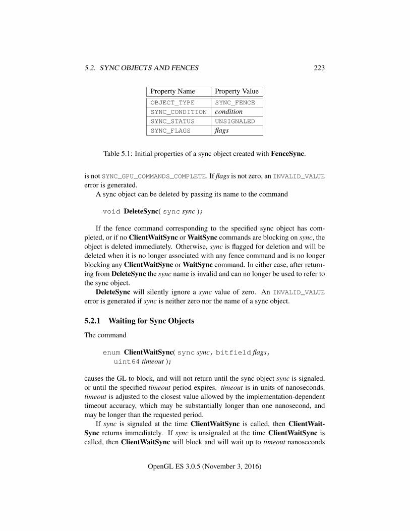
5.2. SYNC OBJECTS AND FENCES 223
Property Name Property ValueOBJECT_TYPE SYNC_FENCE
SYNC_CONDITION conditionSYNC_STATUS UNSIGNALED
SYNC_FLAGS flags
Table 5.1: Initial properties of a sync object created with FenceSync.
is not SYNC_GPU_COMMANDS_COMPLETE. If flags is not zero, an INVALID_VALUEerror is generated.
A sync object can be deleted by passing its name to the command
void DeleteSync( sync sync );
If the fence command corresponding to the specified sync object has com-pleted, or if no ClientWaitSync or WaitSync commands are blocking on sync, theobject is deleted immediately. Otherwise, sync is flagged for deletion and will bedeleted when it is no longer associated with any fence command and is no longerblocking any ClientWaitSync or WaitSync command. In either case, after return-ing from DeleteSync the sync name is invalid and can no longer be used to refer tothe sync object.
DeleteSync will silently ignore a sync value of zero. An INVALID_VALUE
error is generated if sync is neither zero nor the name of a sync object.
5.2.1 Waiting for Sync Objects
The command
enum ClientWaitSync( sync sync, bitfield flags,uint64 timeout );
causes the GL to block, and will not return until the sync object sync is signaled,or until the specified timeout period expires. timeout is in units of nanoseconds.timeout is adjusted to the closest value allowed by the implementation-dependenttimeout accuracy, which may be substantially longer than one nanosecond, andmay be longer than the requested period.
If sync is signaled at the time ClientWaitSync is called, then ClientWait-Sync returns immediately. If sync is unsignaled at the time ClientWaitSync iscalled, then ClientWaitSync will block and will wait up to timeout nanoseconds
OpenGL ES 3.0.5 (November 3, 2016)
5.2. SYNC OBJECTS AND FENCES 224
for sync to become signaled. flags controls command flushing behavior, and maybe SYNC_FLUSH_COMMANDS_BIT, as discussed in section 5.2.2.
ClientWaitSync returns one of four status values. A return value ofALREADY_SIGNALED indicates that sync was signaled at the time ClientWait-Sync was called. ALREADY_SIGNALED will always be returned if sync was sig-naled, even if the value of timeout is zero. A return value of TIMEOUT_EXPIREDindicates that the specified timeout period expired before sync was signaled. A re-turn value of CONDITION_SATISFIED indicates that sync was signaled before thetimeout expired. Finally, if an error occurs, in addition to generating a GL erroras specified below, ClientWaitSync immediately returns WAIT_FAILED withoutblocking.
If the value of timeout is zero, then ClientWaitSync does not block, but simplytests the current state of sync. TIMEOUT_EXPIRED will be returned in this case ifsync is not signaled, even though no actual wait was performed.
If sync is not the name of a sync object, an INVALID_VALUE error is gen-erated. If flags contains any bits other than SYNC_FLUSH_COMMANDS_BIT, anINVALID_VALUE error is generated.
The command
void WaitSync( sync sync, bitfield flags,uint64 timeout );
is similar to ClientWaitSync, but instead of blocking and not returning to the ap-plication until sync is signaled, WaitSync returns immediately, instead causing theGL server to block 2 until sync is signaled 3.
sync has the same meaning as for ClientWaitSync.timeout must currently be the special value TIMEOUT_IGNORED, and is not
used. Instead, WaitSync will always wait no longer than an implementation-dependent timeout. The duration of this timeout in nanoseconds may be queriedby calling GetInteger64v with the symbolic constant MAX_SERVER_WAIT_-
TIMEOUT. There is currently no way to determine whether WaitSync unblockedbecause the timeout expired or because the sync object being waited on was sig-naled.
flags must be 0.If an error occurs, WaitSync generates a GL error as specified below, and does
not cause the GL server to block.2The GL server may choose to wait either in the CPU executing server-side code, or in the GPU
hardware if it supports this operation.3WaitSync allows applications to continue to queue commands from the client in anticipation of
the sync being signalled, increasing client-server parallelism.
OpenGL ES 3.0.5 (November 3, 2016)
5.2. SYNC OBJECTS AND FENCES 225
If sync is not the name of a sync object, an INVALID_VALUE error is generated.If timeout is not TIMEOUT_IGNORED or flags is not zero, an INVALID_VALUE erroris generated4.
5.2.1.1 Multiple Waiters
It is possible for both the GL client to be blocked on a sync object in a ClientWait-Sync command, the GL server to be blocked as the result of a previous WaitSynccommand, and for additional WaitSync commands to be queued in the GL server,all for a single sync object. When such a sync object is signaled in this situation,the client will be unblocked, the server will be unblocked, and all such queuedWaitSync commands will continue immediately when they are reached.
See appendix D.2 for more information about blocking on a sync object inmultiple GL contexts.
5.2.2 Signalling
A fence sync object enters the signaled state only once the corresponding fencecommand has completed and signaled the sync object.
If the sync object being blocked upon will not be signaled in finite time (forexample, by an associated fence command issued previously, but not yet flushedto the graphics pipeline), then ClientWaitSync may hang forever. To help preventthis behavior 5, if the SYNC_FLUSH_COMMANDS_BIT bit is set in flags, and syncis unsignaled when ClientWaitSync is called, then the equivalent of Flush will beperformed before blocking on sync.
If a sync object is marked for deletion while a client is blocking on that objectin a ClientWaitSync command, or a GL server is blocking on that object as a resultof a prior WaitSync command, deletion is deferred until the sync object is signaledand all blocked GL clients and servers are unblocked.
Additional constraints on the use of sync objects are discussed in appendix D.State must be maintained to indicate which sync object names are currently in
use. The state require for each sync object in use is an integer for the specific type,an integer for the condition, and a bit indicating whether the object is signaled
4 flags and timeout are placeholders for anticipated future extensions of sync object capabilities.They must have these reserved values in order that existing code calling WaitSync operate properlyin the presence of such extensions.
5The simple flushing behavior defined by SYNC_FLUSH_COMMANDS_BIT will not helpwhen waiting for a fence command issued in another context’s command stream to complete. Ap-plications which block on a fence sync object must take additional steps to assure that the contextfrom which the corresponding fence command was issued has flushed that command to the graphicspipeline.
OpenGL ES 3.0.5 (November 3, 2016)
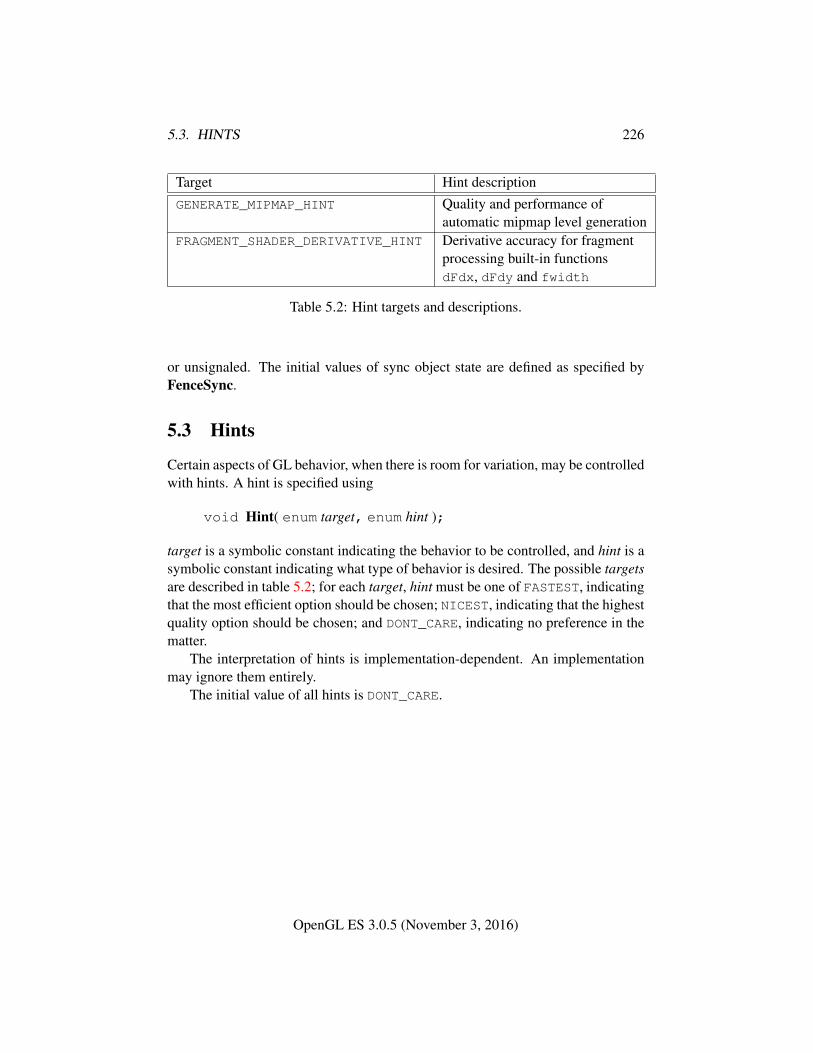
5.3. HINTS 226
Target Hint descriptionGENERATE_MIPMAP_HINT Quality and performance of
automatic mipmap level generationFRAGMENT_SHADER_DERIVATIVE_HINT Derivative accuracy for fragment
processing built-in functionsdFdx, dFdy and fwidth
Table 5.2: Hint targets and descriptions.
or unsignaled. The initial values of sync object state are defined as specified byFenceSync.
5.3 Hints
Certain aspects of GL behavior, when there is room for variation, may be controlledwith hints. A hint is specified using
void Hint( enum target, enum hint );
target is a symbolic constant indicating the behavior to be controlled, and hint is asymbolic constant indicating what type of behavior is desired. The possible targetsare described in table 5.2; for each target, hint must be one of FASTEST, indicatingthat the most efficient option should be chosen; NICEST, indicating that the highestquality option should be chosen; and DONT_CARE, indicating no preference in thematter.
The interpretation of hints is implementation-dependent. An implementationmay ignore them entirely.
The initial value of all hints is DONT_CARE.
OpenGL ES 3.0.5 (November 3, 2016)
Chapter 6
State and State Requests
The state required to describe the GL machine is enumerated in section 6.2. Moststate is set through the calls described in previous chapters, and can be queriedusing the calls described in section 6.1.
6.1 Querying GL State
6.1.1 Simple Queries
Much of the GL state is completely identified by symbolic constants. The valuesof these state variables can be obtained using a set of Get commands. There arefour commands for obtaining simple state variables:
void GetBooleanv( enum pname, boolean *data );void GetIntegerv( enum pname, int *data );void GetInteger64v( enum pname, int64 *data );void GetFloatv( enum pname, float *data );
The commands obtain boolean, integer, 64-bit integer, or floating-point state vari-ables. pname is a symbolic constant indicating the state variable to return. data isa pointer to a scalar or array of the indicated type in which to place the returneddata.
Indexed simple state variables are queried with the commands
void GetIntegeri v( enum target, uint index, int *data );void GetInteger64i v( enum target, uint index,
int64 *data );
227
6.1. QUERYING GL STATE 228
target is the name of the indexed state and index is the index of the particularelement being queried. data is a pointer to a scalar or array of the indicated type inwhich to place the returned data. An INVALID_VALUE error is generated if indexis outside the valid range for the indexed state target.
Finally,
boolean IsEnabled( enum cap );
can be used to determine if cap is currently enabled (as with Enable) or disabled.
6.1.2 Data Conversions
If a Get command is issued that returns value types different from the type of thevalue being obtained, a type conversion is performed. If GetBooleanv is called, afloating-point or integer value converts to FALSE if and only if it is zero (otherwiseit converts to TRUE). If any of the other simple queries are called, a boolean valueof TRUE or FALSE is interpreted as 1 or 0, respectively. If GetIntegerv or GetInte-ger64v are called, a floating-point value is rounded to the nearest integer, unlessthe value is an RGBA color component, a DepthRangef value, or a depth bufferclear value. In these cases, the Get command converts the floating-point value toan integer according to the INT entry of table 4.5; a value not in [−1, 1] convertsto an undefined value. If GetFloatv is called, a boolean value of TRUE or FALSEis interpreted as 1.0 or 0.0, respectively, and an integer is coerced to floating-point.If a value is so large in magnitude that it cannot be represented with the requestedtype, then the nearest value representable using the requested type is returned.
Unless otherwise indicated, multi-valued state variables return their multiplevalues in the same order as they are given as arguments to the commands that setthem. For instance, the two DepthRangef parameters are returned in the order nfollowed by f.
Most texture state variables are qualified by the value of ACTIVE_TEXTURE todetermine which server texture state vector is queried. Table 6.8 indicates thosestate variables which are qualified by ACTIVE_TEXTURE during state queries.
Vertex array state variables are qualified by the value of VERTEX_ARRAY_-BINDING to determine which vertex array object is queried. Table 6.2 defines theset of state stored in a vertex array object.
6.1.3 Enumerated Queries
Other commands exist to obtain state variables that are identified by a category aswell as a symbolic constant.
The commands
OpenGL ES 3.0.5 (November 3, 2016)
6.1. QUERYING GL STATE 229
void GetTexParameter{if}v( enum target, enum value,T data );
place information about texture parameter value for the specified target into data.value must be TEXTURE_IMMUTABLE_FORMAT, TEXTURE_IMMUTABLE_LEVELS,or one of the symbolic values in table 3.20.
target may be one of TEXTURE_2D, TEXTURE_3D, TEXTURE_2D_ARRAY,or TEXTURE_CUBE_MAP, indicating the currently bound two-dimensional, three-dimensional, two-dimensional array, or cube map texture object.
6.1.4 Texture Queries
The command
boolean IsTexture( uint texture );
returns TRUE if texture is the name of a texture object. If texture is zero, or is a non-zero value that is not the name of a texture object, or if an error condition occurs,IsTexture returns FALSE.
6.1.5 Sampler Queries
The command
boolean IsSampler( uint sampler );
may be called to determine whether sampler is the name of a sampler object. Is-Sampler will return TRUE if sampler is the name of a sampler object previouslyreturned from a call to GenSamplers and FALSE otherwise. Zero is not the nameof a sampler object.
The current values of the parameters of a sampler object may be queried bycalling
void GetSamplerParameter{if}v( uint sampler,enum pname, T *params );
sampler is the name of the sampler object from which to retrieve parameters.pname is the name of the parameter to be queried. params is the address of anarray into which the current value of the parameter will be placed. GetSampler-Parameter* accepts the same values for pname as SamplerParameter* (see sec-tion 3.8.2). An INVALID_OPERATION error is generated if sampler is not thename of a sampler object previously returned from a call to GenSamplers. AnINVALID_ENUM error is generated if pname is not the name of a parameter ac-cepted by GetSamplerParameter*.
OpenGL ES 3.0.5 (November 3, 2016)
6.1. QUERYING GL STATE 230
6.1.6 String Queries
String queries return pointers to UTF-8 encoded, null-terminated static stringsdescribing properties of the current GL context1. The command
ubyte *GetString( enum name );
accepts name values of RENDERER, VENDOR, EXTENSIONS, VERSION, andSHADING_LANGUAGE_VERSION. The format of the RENDERER and VENDOR
strings is implementation-dependent.The EXTENSIONS string contains a space separated list of extension names (the
extension names themselves do not contain any spaces).The VERSION string is laid out as follows:
"OpenGL ES N.M vendor-specific information"
The SHADING_LANGUAGE_VERSION string is laid out as follows:
"OpenGL ES GLSL ES N.M vendor-specificinformation"
The version number is either of the form major number.minor number or major -number.minor number.release number, where the numbers all have one or moredigits. The minor number for SHADING_LANGUAGE_VERSION is always two dig-its, matching the OpenGL ES Shading Language Specification release number.For example, this query might return the string "3.00" while the correspondingVERSION query returns "3.0". The release number and vendor specific infor-mation are optional. However, if present, then they pertain to the server and theirformat and contents are implementation-dependent.
GetString returns the version number (in the VERSION string) and the exten-sion names (in the EXTENSIONS string) that can be supported by the current GLcontext. Thus, if the client and server support different versions and/or extensions,a compatible version and list of extensions is returned.
The version of the context may also be queried by calling GetIntegerv withvalues MAJOR_VERSION and MINOR_VERSION, which respectively return thesame values as major number and minor number in the VERSION string.
Indexed strings are queried with the command
ubyte *GetStringi( enum name, uint index );1Applications making copies of these static strings should never use a fixed-length buffer, because
the strings may grow unpredictably between releases, resulting in buffer overflow when copying.This is particularly true of the EXTENSIONS string, which has become extremely long in some
GL implementations.
OpenGL ES 3.0.5 (November 3, 2016)
6.1. QUERYING GL STATE 231
name is the name of the indexed state and index is the index of the particular ele-ment being queried. name may only be EXTENSIONS, indicating that the extensionname corresponding to the indexth supported extension should be returned. indexmay range from zero to the value of NUM_EXTENSIONS minus one. All extensionnames, and only the extension names returned in GetString(EXTENSIONS) willbe returned as individual names, but there is no defined relationship between theorder in which names appear in the non-indexed string and the order in which theappear in the indexed query. There is no defined relationship between any particu-lar extension name and the index values; an extension name may correspond to adifferent index in different GL contexts and/or implementations.
An INVALID_VALUE error is generated if index is outside the valid range forthe indexed state name.
6.1.7 Asynchronous Queries
The command
boolean IsQuery( uint id );
returns TRUE if id is the name of a query object. If id is zero, or if id is a non-zerovalue that is not the name of a query object, IsQuery returns FALSE.
Information about a query target can be queried with the command
void GetQueryiv( enum target, enum pname, int *params );
target identifies the query target, and must be one of ANY_SAMPLES_-
PASSED or ANY_SAMPLES_PASSED_CONSERVATIVE for occlusion queries, orTRANSFORM_FEEDBACK_PRIMITIVES_WRITTEN for primitive queries.
pname must be CURRENT_QUERY. The name of the currently active query fortarget, or zero if no query is active, will be placed in params.
The state of a query object can be queried with the command
void GetQueryObjectuiv( uint id, enum pname,uint *params );
If id is not the name of a query object, or if the query object named by id is currentlyactive, then an INVALID_OPERATION error is generated. pname must be QUERY_-RESULT or QUERY_RESULT_AVAILABLE.
There may be an indeterminate delay before a query object’s result value isavailable. If pname is QUERY_RESULT_AVAILABLE, FALSE is returned if such adelay would be required; otherwise TRUE is returned. It must always be true that
OpenGL ES 3.0.5 (November 3, 2016)
6.1. QUERYING GL STATE 232
if any query object returns a result available of TRUE, all queries of the same typeissued prior to that query must also return TRUE.
If pname is QUERY_RESULT, then the query object’s result value is returned asa single integer in params. If the value is so large in magnitude that it cannot berepresented with the requested type, then the nearest value representable using therequested type is returned. Querying QUERY_RESULT for any given query objectforces that query to complete within a finite amount of time.
Repeatedly querying the QUERY_RESULT_AVAILABLE state for any givenquery object is guaranteed to return true eventually. Note that multiple queriesto the same occlusion object may result in a significant performance loss. For bet-ter performance it is recommended to wait N frames before querying this state. Nis implementation-dependent but is generally between one and three.
If multiple queries are issued using the same object name prior to calling Get-QueryObjectuiv, the result and availability information returned will always befrom the last query issued. The results from any queries before the last one will belost if they are not retrieved before starting a new query on the same target and id.
6.1.8 Sync Object Queries
Properties of sync objects may be queried using the command
void GetSynciv( sync sync, enum pname, sizei bufSize,sizei *length, int *values );
The value or values being queried are returned in the parameters length andvalues.
On success, GetSynciv replaces up to bufSize integers in values with the cor-responding property values of the object being queried. The actual number ofintegers replaced is returned in *length. If length is NULL, no length is returned.
If pname is OBJECT_TYPE, a single value representing the specific type of thesync object is placed in values. The only type supported is SYNC_FENCE.
If pname is SYNC_STATUS, a single value representing the status of the syncobject (SIGNALED or UNSIGNALED) is placed in values.
If pname is SYNC_CONDITION, a single value representing the condition ofthe sync object is placed in values. The only condition supported is SYNC_GPU_-COMMANDS_COMPLETE.
If pname is SYNC_FLAGS, a single value representing the flags with which thesync object was created is placed in values. No flags are currently supported.
If sync is not the name of a sync object, an INVALID_VALUE error is generated.If pname is not one of the values described above, an INVALID_ENUM error isgenerated. If an error occurs, nothing will be written to values or length.
OpenGL ES 3.0.5 (November 3, 2016)
6.1. QUERYING GL STATE 233
The command
boolean IsSync( sync sync );
returns TRUE if sync is the name of a sync object. If sync is not the name of a syncobject, or if an error condition occurs, IsSync returns FALSE (note that zero is notthe name of a sync object).
Sync object names immediately become invalid after calling DeleteSync, asdiscussed in sections 5.2 and D.2, but the underlying sync object will not be deleteduntil it is no longer associated with any fence command and no longer blocking any*WaitSync command.
6.1.9 Buffer Object Queries
The command
boolean IsBuffer( uint buffer );
returns TRUE if buffer is the name of a buffer object. If buffer is zero, or if buffer isa non-zero value that is not the name of an buffer object, IsBuffer returns FALSE.
The commands
void GetBufferParameteriv( enum target, enum pname,int *data );
void GetBufferParameteri64v( enum target, enum pname,int64 *data );
return information about a bound buffer object. target must be one of the targetslisted in table 2.6, and pname must be one of the buffer object parameters in ta-ble 2.7, other than BUFFER_MAP_POINTER. The value of the specified parameterof the buffer object bound to target is returned in data.
While the data store of a buffer object is mapped, the pointer to the data storecan be queried by calling
void GetBufferPointerv( enum target, enum pname,void **params );
with target set to one of the targets listed in table 2.6 and pname set to BUFFER_-
MAP_POINTER. The single buffer map pointer is returned in params. GetBuffer-Pointerv returns the NULL pointer value if the buffer’s data store is not currentlymapped, or if the requesting client did not map the buffer object’s data store, andthe implementation is unable to support mappings on multiple clients.
OpenGL ES 3.0.5 (November 3, 2016)
6.1. QUERYING GL STATE 234
To query which buffer objects are bound to the array of uniform buffer bindingpoints and will be used as the storage for active uniform blocks, call GetIntegeri vwith param set to UNIFORM_BUFFER_BINDING. index must be in the range zeroto the value of MAX_UNIFORM_BUFFER_BINDINGS minus one. The name of thebuffer object bound to index is returned in values. If no buffer object is bound forindex, zero is returned in values.
To query the starting offset or size of the range of each buffer object bind-ing used for uniform buffers, call GetInteger64i v with param set to UNIFORM_-
BUFFER_START or UNIFORM_BUFFER_SIZE respectively. index must be in therange zero to the value of MAX_UNIFORM_BUFFER_BINDINGS minus one. If theparameter (starting offset or size) was not specified when the buffer object wasbound (e.g. if bound with BindBufferBase), or if no buffer object is bound toindex, zero is returned2.
To query which buffer objects are bound to the array of transform feedbackbinding points and will be used when transform feedback is active, call GetInte-geri v with param set to TRANSFORM_FEEDBACK_BUFFER_BINDING. index mustbe in the range zero to the value of MAX_TRANSFORM_FEEDBACK_SEPARATE_-ATTRIBS minus one. The name of the buffer object bound to index is returned invalues. If no buffer object is bound for index, zero is returned in values.
To query the starting offset or size of the range of each buffer ob-ject binding used for transform feedback, call GetInteger64i v with paramset to TRANSFORM_FEEDBACK_BUFFER_START or TRANSFORM_FEEDBACK_-
BUFFER_SIZE respectively. index must be in the range 0 to the value of MAX_-TRANSFORM_FEEDBACK_SEPARATE_ATTRIBSminus one. If the parameter (start-ing offset or size) was not specified when the buffer object was bound (e.g. if boundwith BindBufferBase), or if no buffer object is bound to index, zero is returned2.
6.1.10 Vertex Array Object Queries
The command
boolean IsVertexArray( uint array );
returns TRUE if array is the name of a vertex array object. If array is zero, or anon-zero value that is not the name of a vertex array object, IsVertexArray returnsFALSE. No error is generated if array is not a valid vertex array object name.
2A zero size is a sentinel value indicating that the actual binding range size is determined by thesize of the bound buffer at the time the binding is used.
OpenGL ES 3.0.5 (November 3, 2016)
6.1. QUERYING GL STATE 235
6.1.11 Transform Feedback Queries
The command
boolean IsTransformFeedback( uint id );
returns TRUE if id is the name of a transform feedback object. If id is zero, ora non-zero value that is not the name of a transform feedback object, IsTrans-formFeedback returns FALSE. No error is generated if id is not a valid transformfeedback object name.
6.1.12 Shader and Program Queries
State stored in shader or program objects can be queried by commands that ac-cept shader or program object names. These commands will generate the errorINVALID_VALUE if the provided name is not the name of either a shader or pro-gram object, and INVALID_OPERATION if the provided name identifies an objectof the other type. If an error is generated, variables used to hold return values arenot modified.
The command
boolean IsShader( uint shader );
returns TRUE if shader is the name of a shader object. If shader is zero, or a non-zero value that is not the name of a shader object, IsShader returns FALSE. Noerror is generated if shader is not a valid shader object name.
The command
void GetShaderiv( uint shader, enum pname, int *params );
returns properties of the shader object named shader in params. The parametervalue to return is specified by pname.
If pname is SHADER_TYPE, VERTEX_SHADER or FRAGMENT_SHADER is re-turned if shader is a vertex or fragment shader object respectively. If pname isDELETE_STATUS, TRUE is returned if the shader has been flagged for deletion andFALSE is returned otherwise. If pname is COMPILE_STATUS, TRUE is returnedif the shader was last compiled successfully, and FALSE is returned otherwise. Ifpname is INFO_LOG_LENGTH, the length of the info log, including a null termi-nator, is returned. If there is no info log, zero is returned. If pname is SHADER_-SOURCE_LENGTH, the length of the concatenation of the source strings making upthe shader source, including a null terminator, is returned. If no source has beendefined, zero is returned.
The command
OpenGL ES 3.0.5 (November 3, 2016)
6.1. QUERYING GL STATE 236
boolean IsProgram( uint program );
returns TRUE if program is the name of a program object. If program is zero, or anon-zero value that is not the name of a program object, IsProgram returns FALSE.No error is generated if program is not a valid program object name.
The command
void GetProgramiv( uint program, enum pname,int *params );
returns properties of the program object named program in params. The parametervalue to return is specified by pname.
Most properties set within program objects are specified not to take effect untilthe next call to LinkProgram or ProgramBinary. Some properties further requirea successful call to either of these commands before taking effect. GetProgramivreturns the properties currently in effect for program, which may differ from theproperties set within program since the most recent call to LinkProgram or Pro-gramBinary, which have not yet taken effect. If there has been no such call puttingchanges to pname into effect, initial values are returned.
If pname is DELETE_STATUS, TRUE is returned if the program has been flaggedfor deletion, and FALSE is returned otherwise. If pname is LINK_STATUS, TRUEis returned if the program was last linked successfully, and FALSE is returnedotherwise. If pname is VALIDATE_STATUS, TRUE is returned if the last call toValidateProgram with program was successful, and FALSE is returned other-wise. If pname is INFO_LOG_LENGTH, the length of the info log, including anull terminator, is returned. If there is no info log, zero is returned. If pnameis ATTACHED_SHADERS, the number of objects attached is returned. If pname isACTIVE_ATTRIBUTES, the number of active attributes in program is returned. Ifno active attributes exist, zero is returned. If pname is ACTIVE_ATTRIBUTE_-MAX_LENGTH, the length of the longest active attribute name, including a nullterminator, is returned. If no active attributes exist, zero is returned. If pnameis ACTIVE_UNIFORMS, the number of active uniforms is returned. If no activeuniforms exist, zero is returned. If pname is ACTIVE_UNIFORM_MAX_LENGTH,the length of the longest active uniform name, including a null terminator, is re-turned. If no active uniforms exist, zero is returned. If pname is TRANSFORM_-FEEDBACK_BUFFER_MODE, the buffer mode used when transform feedback isactive is returned. It can be one of SEPARATE_ATTRIBS or INTERLEAVED_-ATTRIBS. If pname is TRANSFORM_FEEDBACK_VARYINGS, the number of out-put variables to capture in transform feedback mode for the program is returned.If pname is TRANSFORM_FEEDBACK_VARYING_MAX_LENGTH, the length of the
OpenGL ES 3.0.5 (November 3, 2016)
6.1. QUERYING GL STATE 237
longest output variable name specified to be used for transform feedback, includ-ing a null terminator, is returned. If no outputs are used for transform feedback,zero is returned. If pname is ACTIVE_UNIFORM_BLOCKS, the number of uniformblocks for program containing active uniforms is returned. If pname is ACTIVE_-UNIFORM_BLOCK_MAX_NAME_LENGTH, the length of the longest active uniformblock name, including the null terminator, is returned. If pname is PROGRAM_-BINARY_RETRIEVABLE_HINT, the value of whether the binary retrieval hint isenabled for program is returned.
The command
void GetAttachedShaders( uint program, sizei maxCount,sizei *count, uint *shaders );
returns the names of shader objects attached to program in shaders. The actualnumber of shader names written into shaders is returned in count. If no shaders areattached, count is set to zero. If count is NULL then it is ignored. The maximumnumber of shader names that may be written into shaders is specified by maxCount.The number of objects attached to program is given by can be queried by callingGetProgramiv with ATTACHED_SHADERS.
A string that contains information about the last compilation attempt on ashader object or last link or validation attempt on a program object, called theinfo log, can be obtained with the commands
void GetShaderInfoLog( uint shader, sizei bufSize,sizei *length, char *infoLog );
void GetProgramInfoLog( uint program, sizei bufSize,sizei *length, char *infoLog );
These commands return the info log string in infoLog. This string will be null-terminated. The actual number of characters written into infoLog, excluding thenull terminator, is returned in length. If length is NULL, then no length is returned.The maximum number of characters that may be written into infoLog, includingthe null terminator, is specified by bufSize. The number of characters in the infolog can be queried with GetShaderiv or GetProgramiv with INFO_LOG_LENGTH.If shader is a shader object, the returned info log will either be an empty string orit will contain information about the last compilation attempt for that object. Ifprogram is a program object, the returned info log will either be an empty string orit will contain information about the last link attempt or last validation attempt forthat object.
OpenGL ES 3.0.5 (November 3, 2016)
6.1. QUERYING GL STATE 238
The info log is typically only useful during application development and anapplication should not expect different GL implementations to produce identicalinfo logs.
The command
void GetShaderSource( uint shader, sizei bufSize,sizei *length, char *source );
returns in source the string making up the source code for the shader object shader.The string source will be null-terminated. The actual number of characters writteninto source, excluding the null terminator, is returned in length. If length is NULL,no length is returned. The maximum number of characters that may be written intosource, including the null terminator, is specified by bufSize. The string source isa concatenation of the strings passed to the GL using ShaderSource. The lengthof this concatenation is given by SHADER_SOURCE_LENGTH, which can be queriedwith GetShaderiv.
The command
void GetShaderPrecisionFormat( enum shadertype,enum precisiontype, int *range, int *precision );
returns the range and precision for different numeric formats supported by theshader compiler. shadertype must be VERTEX_SHADER or FRAGMENT_SHADER.precisiontype must be one of LOW_FLOAT, MEDIUM_FLOAT, HIGH_FLOAT, LOW_-INT, MEDIUM_INT or HIGH_INT. range points to an array of two integers in whichencodings of the format’s numeric range are returned. If min and max are thesmallest and largest values representable in the format, then the values returned aredefined to be
range[0] = blog2(|min|)c
range[1] = blog2(|max|)c
precision points to an integer in which the log2 value of the number of bits ofprecision of the format is returned. If the smallest representable value greater than1 is 1 + ε, then *precision will contain b−log2(ε)c, and every value in the range
[−2range[0], 2range[1]]
can be represented to at least one part in 2∗precision. For example, an IEEE single-precision floating-point format would return range[0] = 127, range[1] = 127,
OpenGL ES 3.0.5 (November 3, 2016)
6.1. QUERYING GL STATE 239
and ∗precision = 23, while a 32-bit two’s-complement integer format would re-turn range[0] = 31, range[1] = 30, and ∗precision = 0.
The minimum required precision and range for formats corresponding to thedifferent values of precisiontype are described in section 4.5 of the OpenGL ESShading Language specification.
The commands
void GetVertexAttribfv( uint index, enum pname,float *params );
void GetVertexAttribiv( uint index, enum pname,int *params );
void GetVertexAttribIiv( uint index, enum pname,int *params );
void GetVertexAttribIuiv( uint index, enum pname,uint *params );
obtain the vertex attribute state named by pname for the generic vertex attributenumbered index and places the information in the array params. pname mustbe one of VERTEX_ATTRIB_ARRAY_BUFFER_BINDING, VERTEX_ATTRIB_-
ARRAY_ENABLED, VERTEX_ATTRIB_ARRAY_SIZE, VERTEX_-
ATTRIB_ARRAY_STRIDE, VERTEX_ATTRIB_ARRAY_TYPE, VERTEX_ATTRIB_-ARRAY_NORMALIZED, VERTEX_ATTRIB_ARRAY_INTEGER, VERTEX_ATTRIB_-ARRAY_DIVISOR, or CURRENT_VERTEX_ATTRIB. Note that all the queries exceptCURRENT_VERTEX_ATTRIB return values stored in the currently bound vertex ar-ray object (the value of VERTEX_ARRAY_BINDING). If the zero object is bound,these values are client state. The error INVALID_VALUE is generated if index isgreater than or equal to MAX_VERTEX_ATTRIBS.
All but CURRENT_VERTEX_ATTRIB return information about generic vertexattribute arrays. The enable state of a generic vertex attribute array is set by thecommand EnableVertexAttribArray and cleared by DisableVertexAttribArray.The size, stride, type, normalized flag, and unconverted integer flag are set by thecommands VertexAttribPointer and VertexAttribIPointer. The normalized flagis always set to FALSE by VertexAttribIPointer. The unconverted integer flag isalways set to FALSE by VertexAttribPointer and TRUE by VertexAttribIPointer.
The query CURRENT_VERTEX_ATTRIB returns the current value for thegeneric attribute index. GetVertexAttribfv reads and returns the current attributevalues as floating-point values; GetVertexAttribiv reads them as floating-pointvalues and converts them to integer values; GetVertexAttribIiv reads and returnsthem as integers; GetVertexAttribIuiv reads and returns them as unsigned inte-gers. The results of the query are undefined if the current attribute values are readusing one data type but were specified using a different one.
OpenGL ES 3.0.5 (November 3, 2016)
6.1. QUERYING GL STATE 240
The command
void GetVertexAttribPointerv( uint index, enum pname,void **pointer );
obtains the pointer named pname for the vertex attribute numbered index and placesthe information in the array pointer. pname must be VERTEX_ATTRIB_ARRAY_-POINTER. The value returned is queried from the currently bound vertex arrayobject. If the zero object is bound, the value is queried from client state. AnINVALID_VALUE error is generated if index is greater than or equal to the value ofMAX_VERTEX_ATTRIBS.
The commands
void GetUniformfv( uint program, int location,float *params );
void GetUniformiv( uint program, int location,int *params );
void GetUniformuiv( uint program, int location,uint *params );
return the value or values of the uniform at location location of the default uni-form block for program object program in the array params. The type of the uni-form at location determines the number of values returned. The error INVALID_-OPERATION is generated if program has not been linked successfully, or if locationis not a valid location for program. In order to query the values of an array of uni-forms, a GetUniform* command needs to be issued for each array element. If theuniform queried is a matrix, the values of the matrix are returned in column majororder. If an error occurred, params will not be modified.
6.1.13 Framebuffer Object Queries
The command
boolean IsFramebuffer( uint framebuffer );
returns TRUE if framebuffer is the name of a framebuffer object. If framebuffer iszero, or if framebuffer is a non-zero value that is not the name of an framebufferobject, IsFramebuffer returns FALSE.
The command
void GetFramebufferAttachmentParameteriv( enum target,enum attachment, enum pname, int *params );
OpenGL ES 3.0.5 (November 3, 2016)
6.1. QUERYING GL STATE 241
returns information about attachments of a bound framebuffer object. tar-get must be DRAW_FRAMEBUFFER, READ_FRAMEBUFFER, or FRAMEBUFFER.FRAMEBUFFER is equivalent to DRAW_FRAMEBUFFER.
If the default framebuffer is bound to target, then attachment must be BACK,identifying the color buffer; DEPTH, identifying the depth buffer; or STENCIL,identifying the stencil buffer.
Otherwise, attachment must be one of the attachment points of the framebufferlisted in table 4.6.
If attachment is DEPTH_STENCIL_ATTACHMENT, the same object must bebound to both the depth and stencil attachment points of the framebuffer object,and information about that object is returned.
Upon successful return from GetFramebufferAttachmentParameteriv, ifpname is FRAMEBUFFER_ATTACHMENT_OBJECT_TYPE, then params will containone of NONE, FRAMEBUFFER_DEFAULT, TEXTURE, or RENDERBUFFER, identify-ing the type of object which contains the attached image. Other values acceptedfor pname depend on the type of object, as described below.
If the value of FRAMEBUFFER_ATTACHMENT_OBJECT_TYPE is NONE, then noframebuffer is bound to target. In this case querying pname FRAMEBUFFER_-
ATTACHMENT_OBJECT_NAME will return zero, and all other queries will generatean INVALID_OPERATION error.
If the value of FRAMEBUFFER_ATTACHMENT_OBJECT_TYPE is not NONE,these queries apply to all other framebuffer types:
• If pname is FRAMEBUFFER_ATTACHMENT_RED_SIZE, FRAMEBUFFER_-
ATTACHMENT_GREEN_SIZE, FRAMEBUFFER_ATTACHMENT_BLUE_-
SIZE, FRAMEBUFFER_ATTACHMENT_ALPHA_SIZE, FRAMEBUFFER_-
ATTACHMENT_DEPTH_SIZE, or FRAMEBUFFER_ATTACHMENT_-
STENCIL_SIZE, then params will contain the number of bits in thecorresponding red, green, blue, alpha, depth, or stencil component ofthe specified attachment. If the requested component is not present inattachment, zero is returned.
• If pname is FRAMEBUFFER_ATTACHMENT_COMPONENT_TYPE, params willcontain the format of components of the specified attachment, one of FLOAT,INT, UNSIGNED_INT, SIGNED_NORMALIZED, or UNSIGNED_NORMALIZEDfor floating-point, signed integer, unsigned integer, signed normalized fixed-point, or unsigned normalized fixed-point components respectively. Ifno data storage or texture image has been specified for the attachment,params will contain NONE. This query cannot be performed for a combineddepth+stencil attachment, since it does not have a single format.
OpenGL ES 3.0.5 (November 3, 2016)
6.1. QUERYING GL STATE 242
• If pname is FRAMEBUFFER_ATTACHMENT_COLOR_ENCODING, params willcontain the encoding of components of the specified attachment, one ofLINEAR or SRGB for linear or sRGB-encoded components, respectively.Only color buffer components may be sRGB-encoded; such componentsare treated as described in sections 4.1.7 and 4.1.8. For the default frame-buffer, color encoding is determined by the implementation. For framebufferobjects, components are sRGB-encoded if the internal format of a colorattachment is one of the color-renderable sRGB formats described in sec-tion 3.8.16. If attachment is not a color attachment, or no data storage ortexture image has been specified for the attachment, params will contain thevalue LINEAR.
If the value of FRAMEBUFFER_ATTACHMENT_OBJECT_TYPE isRENDERBUFFER, then
• If pname is FRAMEBUFFER_ATTACHMENT_OBJECT_NAME, params will con-tain the name of the renderbuffer object which contains the attached image.
If the value of FRAMEBUFFER_ATTACHMENT_OBJECT_TYPE is TEXTURE, then
• If pname is FRAMEBUFFER_ATTACHMENT_OBJECT_NAME, then params willcontain the name of the texture object which contains the attached image.
• If pname is FRAMEBUFFER_ATTACHMENT_TEXTURE_LEVEL, then paramswill contain the mipmap level of the texture object which contains the at-tached image.
• If pname is FRAMEBUFFER_ATTACHMENT_TEXTURE_CUBE_MAP_FACE andthe texture object named FRAMEBUFFER_ATTACHMENT_OBJECT_NAME is acube map texture, then params will contain the cube map face of the cube-map texture object which contains the attached image. Otherwise paramswill contain the value zero.
• If pname is FRAMEBUFFER_ATTACHMENT_TEXTURE_LAYER and the valueof FRAMEBUFFER_ATTACHMENT_OBJECT_NAME is the name of a three-dimensional texture or a two-dimensional array texture, then params willcontain the texture layer which contains the attached image. Otherwiseparams will contain zero.
OpenGL ES 3.0.5 (November 3, 2016)
6.1. QUERYING GL STATE 243
Errors
An INVALID_ENUM error is generated if target is not DRAW_-
FRAMEBUFFER, READ_FRAMEBUFFER, or FRAMEBUFFER.An INVALID_OPERATION error is generated if the default framebuffer is
bound to target and attachment is not BACK, DEPTH, or STENCIL.An INVALID_OPERATION error is generated if a framebuffer object is
bound to target and attachment is COLOR_ATTACHMENTm where m is greaterthan or equal to the value of MAX_COLOR_ATTACHMENTS.
An INVALID_ENUM error is generated if a framebuffer object is bound totarget, attachment is not one of the attachments in table 4.6, and attachmentis not COLOR_ATTACHMENTm where m is greater than or equal to the value ofMAX_COLOR_ATTACHMENTS.
An INVALID_ENUM error is generated by any combinations of framebuffertype and pname not described above.
An INVALID_OPERATION erroris generated if the value of FRAMEBUFFER_ATTACHMENT_OBJECT_TYPE isNONE and pname is not FRAMEBUFFER_ATTACHMENT_OBJECT_NAME.
An INVALID_OPERATION error is generated if attachment is DEPTH_-
STENCIL_ATTACHMENT and pname is FRAMEBUFFER_ATTACHMENT_-
COMPONENT_TYPE.An INVALID_OPERATION error is generated if attachment is DEPTH_-
STENCIL_ATTACHMENT and different objects are bound to the depth and sten-cil attachment points of target.
6.1.14 Renderbuffer Object Queries
The command
boolean IsRenderbuffer( uint renderbuffer );
returns TRUE if renderbuffer is the name of a renderbuffer object. If renderbufferis zero, or if renderbuffer is a non-zero value that is not the name of a renderbufferobject, IsRenderbuffer returns FALSE.
The command
void GetRenderbufferParameteriv( enum target, enum pname,int* params );
returns information about a bound renderbuffer object. target must beRENDERBUFFER and pname must be one of the symbolic values in table 6.15. If
OpenGL ES 3.0.5 (November 3, 2016)
6.1. QUERYING GL STATE 244
the renderbuffer currently bound to target is zero, then an INVALID_OPERATION
error is generated.Upon successful return from GetRenderbufferParameteriv, if pname
is RENDERBUFFER_WIDTH, RENDERBUFFER_HEIGHT, RENDERBUFFER_-
INTERNAL_FORMAT, or RENDERBUFFER_SAMPLES, then params will containthe width in pixels, height in pixels, internal format, or number of samples,respectively, of the image of the renderbuffer currently bound to target.
If pname is RENDERBUFFER_RED_SIZE, RENDERBUFFER_GREEN_-
SIZE, RENDERBUFFER_BLUE_SIZE, RENDERBUFFER_ALPHA_SIZE,RENDERBUFFER_DEPTH_SIZE, or RENDERBUFFER_STENCIL_SIZE, thenparams will contain the actual resolutions (not the resolutions specified whenthe image array was defined) for the red, green, blue, alpha depth, or stencilcomponents, respectively, of the image of the renderbuffer currently bound totarget.
Otherwise, an INVALID_ENUM error is generated.
6.1.15 Internal Format Queries
Information about implementation-dependent support for internal formats can bequeried with the command
void GetInternalformativ( enum target, enum internalformat,enum pname, sizei bufSize, int *params );
internalformat must be color-renderable, depth-renderable or stencil-renderable (as defined in section 4.4.4).
target indicates the usage of the internalformat, and must be RENDERBUFFER.No more than bufSize integers will be written into params. If more data are
available, they will be ignored and no error will be generated.pname indicates the information to query, and is one of the following:If pname is NUM_SAMPLE_COUNTS, the number of sample counts that would
be returned by querying SAMPLES is returned in params.If pname is SAMPLES, the sample counts supported for internalformat and tar-
get are written into params, in descending numeric order. Only positive values arereturned.
Querying SAMPLES with a bufSize of one will return just the maximum sup-ported number of samples for this format.
Since multisampling is not supported for signed and unsigned integer internalformats, the value of NUM_SAMPLE_COUNTS will be zero for such formats.
OpenGL ES 3.0.5 (November 3, 2016)
6.2. STATE TABLES 245
For every other accepted internalformat, the value of NUM_SAMPLE_COUNTSis guaranteed to be at least one, and the maximum value in SAMPLES is guaranteedto be at least the value of MAX_SAMPLES.
An INVALID_ENUM error is generated if internalformat is not color-, depth- orstencil-renderable; if target is not RENDERBUFFER; or if pname is not SAMPLES orNUM_SAMPLE_COUNTS.
An INVALID_VALUE error is generated if bufSize is negative.
6.2 State Tables
The tables on the following pages indicate which state variables are obtained withwhat commands. State variables that can be obtained using any of GetBooleanv,GetIntegerv, GetInteger64v, or GetFloatv are listed with just one of these com-mands – the one that is most appropriate given the type of the data to be returned.These state variables cannot be obtained using IsEnabled. However, state vari-ables for which IsEnabled is listed as the query command can also be obtainedusing GetBooleanv, GetIntegerv, GetInteger64v, and GetFloatv. State variablesfor which any other command is listed as the query command can be obtained byusing that command or any of its typed variants, although information may be lostwhen not using the listed command. Unless otherwise specified, when floating-point state is returned as integer values or integer state is returned as floating-pointvalues it is converted in the fashion described in section 6.1.2.
State table entries indicate a type is indicated for each variable. Table 6.1explains these types. The type actually identifies all state associated with the indi-cated description; in certain cases only a portion of this state is returned. This is thecase with textures, where only the selected texture or texture parameter is returned.
OpenGL ES 3.0.5 (November 3, 2016)
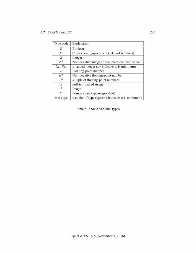
6.2. STATE TABLES 246
Type code ExplanationB BooleanC Color (floating-point R, G, B, and A values)Z IntegerZ+ Non-negative integer or enumerated token value
Zk, Zk∗ k-valued integer (k∗ indicates k is minimum)R Floating-point numberR+ Non-negative floating-point numberRk k-tuple of floating-point numbersS null-terminated stringI ImageY Pointer (data type unspecified)
n× type n copies of type type (n∗ indicates n is minimum)
Table 6.1: State Variable Types
OpenGL ES 3.0.5 (November 3, 2016)
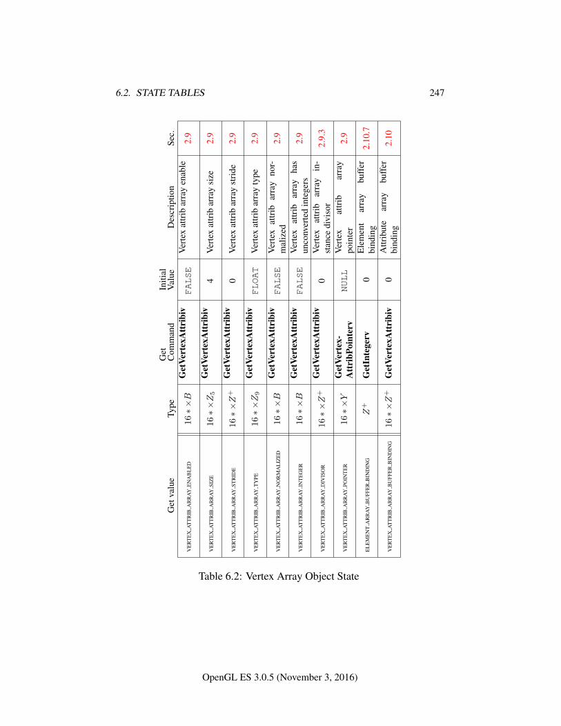
6.2. STATE TABLES 247
Get
valu
eTy
peG
etC
omm
and
Initi
alV
alue
Des
crip
tion
Sec.
VE
RT
EX
AT
TR
IBA
RR
AY
EN
AB
LE
D16∗×B
Get
Vert
exA
ttri
biv
FALSE
Ver
tex
attr
ibar
ray
enab
le2.
9
VE
RT
EX
AT
TR
IBA
RR
AY
SIZ
E16∗×Z5
Get
Vert
exA
ttri
biv
4V
erte
xat
trib
arra
ysi
ze2.
9
VE
RT
EX
AT
TR
IBA
RR
AY
STR
IDE
16∗×Z
+G
etVe
rtex
Att
ribi
v0
Ver
tex
attr
ibar
ray
stri
de2.
9
VE
RT
EX
AT
TR
IBA
RR
AY
TY
PE16∗×Z9
Get
Vert
exA
ttri
biv
FLOAT
Ver
tex
attr
ibar
ray
type
2.9
VE
RT
EX
AT
TR
IBA
RR
AY
NO
RM
AL
IZE
D16∗×B
Get
Vert
exA
ttri
biv
FALSE
Ver
tex
attr
ibar
ray
nor-
mal
ized
2.9
VE
RT
EX
AT
TR
IBA
RR
AY
INT
EG
ER
16∗×B
Get
Vert
exA
ttri
biv
FALSE
Ver
tex
attr
ibar
ray
has
unco
nver
ted
inte
gers
2.9
VE
RT
EX
AT
TR
IBA
RR
AY
DIV
ISO
R16∗×Z
+G
etVe
rtex
Att
ribi
v0
Ver
tex
attr
ibar
ray
in-
stan
cedi
viso
r2.
9.3
VE
RT
EX
AT
TR
IBA
RR
AY
POIN
TE
R16∗×Y
Get
Vert
ex-
Att
ribP
oint
erv
NULL
Ver
tex
attr
ibar
ray
poin
ter
2.9
EL
EM
EN
TA
RR
AY
BU
FFE
RB
IND
ING
Z+
Get
Inte
gerv
0E
lem
ent
arra
ybu
ffer
bind
ing
2.10
.7
VE
RT
EX
AT
TR
IBA
RR
AY
BU
FFE
RB
IND
ING
16∗×Z
+G
etVe
rtex
Att
ribi
v0
Attr
ibut
ear
ray
buff
erbi
ndin
g2.
10
Table 6.2: Vertex Array Object State
OpenGL ES 3.0.5 (November 3, 2016)
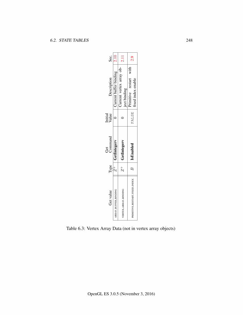
6.2. STATE TABLES 248
Get
valu
eTy
peG
etC
omm
and
Initi
alV
alue
Des
crip
tion
Sec.
AR
RA
YB
UFF
ER
BIN
DIN
GZ
+G
etIn
tege
rv0
Cur
rent
buff
erbi
ndin
g2.
10
VE
RT
EX
AR
RA
YB
IND
ING
Z+
Get
Inte
gerv
0C
urre
ntve
rtex
arra
yob
-je
ctbi
ndin
g2.
11
PRIM
ITIV
ER
EST
AR
TFI
XE
DIN
DE
XB
IsE
nabl
edFALSE
Prim
itive
rest
art
with
fixed
inde
xen
able
2.9
Table 6.3: Vertex Array Data (not in vertex array objects)
OpenGL ES 3.0.5 (November 3, 2016)
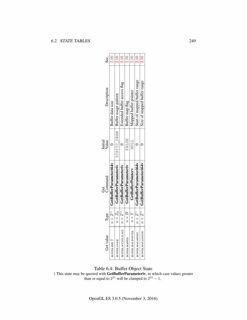
6.2. STATE TABLES 249
Get
valu
eTy
peG
etC
omm
and
Initi
alV
alue
Des
crip
tion
Sec.
BU
FFE
RSI
ZE†
n×Z
+G
etB
uffe
rPar
amet
eri6
4v0
Buf
ferd
ata
size
2.10
BU
FFE
RU
SAG
En×Z9
Get
Buf
ferP
aram
eter
ivSTATIC_DRAW
Buf
feru
sage
patte
rn2.
10B
UFF
ER
AC
CE
SSFL
AG
Sn×Z
+G
etB
uffe
rPar
amet
eriv
0E
xten
ded
buff
erac
cess
flag
2.10
BU
FFE
RM
APP
ED
n×B
Get
Buf
ferP
aram
eter
ivFALSE
Buf
ferm
apfla
g2.
10B
UFF
ER
MA
PPO
INT
ER
n×Y
Get
Buf
ferP
oint
erv
NULL
Map
ped
buff
erpo
inte
r2.
10B
UFF
ER
MA
PO
FFSE
Tn×Z
+G
etB
uffe
rPar
amet
eri6
4v0
Star
tofm
appe
dbu
ffer
rang
e2.
10B
UFF
ER
MA
PL
EN
GT
Hn×Z
+G
etB
uffe
rPar
amet
eri6
4v0
Size
ofm
appe
dbu
ffer
rang
e2.
10
Table 6.4: Buffer Object State† This state may be queried with GetBufferParameteriv, in which case values greater
than or equal to 231 will be clamped to 231 − 1.
OpenGL ES 3.0.5 (November 3, 2016)
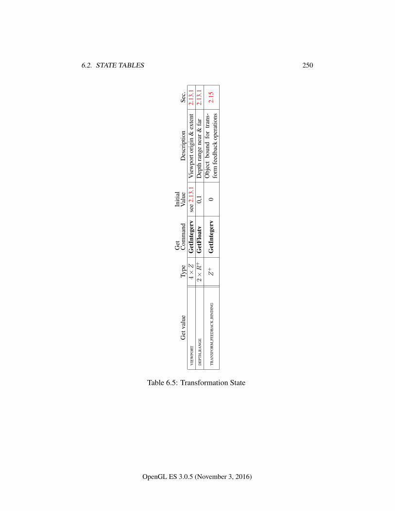
6.2. STATE TABLES 250
Get
valu
eTy
peG
etC
omm
and
Initi
alV
alue
Des
crip
tion
Sec.
VIE
WPO
RT
4×Z
Get
Inte
gerv
see
2.13
.1V
iew
port
orig
in&
exte
nt2.
13.1
DE
PTH
RA
NG
E2×R
+G
etFl
oatv
0,1
Dep
thra
nge
near
&fa
r2.
13.1
TR
AN
SFO
RM
FEE
DB
AC
KB
IND
ING
Z+
Get
Inte
gerv
0O
bjec
tbo
und
for
tran
s-fo
rmfe
edba
ckop
erat
ions
2.15
Table 6.5: Transformation State
OpenGL ES 3.0.5 (November 3, 2016)
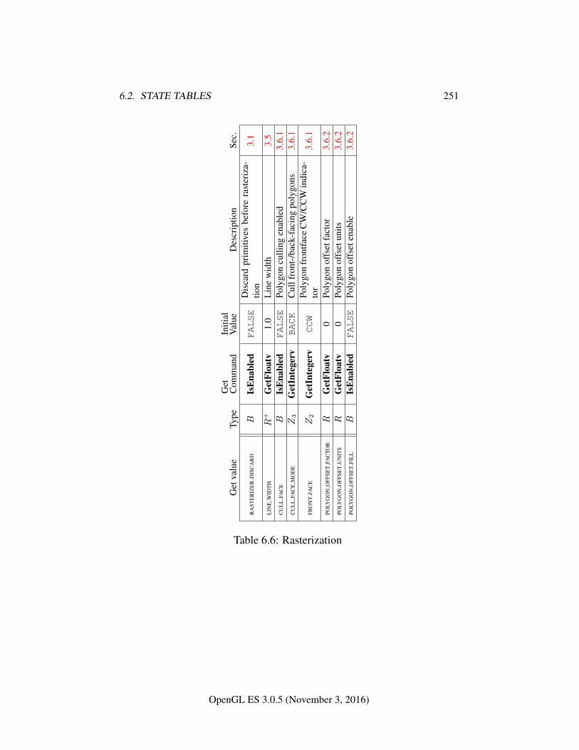
6.2. STATE TABLES 251
Get
valu
eTy
peG
etC
omm
and
Initi
alV
alue
Des
crip
tion
Sec.
RA
STE
RIZ
ER
DIS
CA
RD
BIs
Ena
bled
FALSE
Dis
card
prim
itive
sbe
fore
rast
eriz
a-tio
n3.
1
LIN
EW
IDT
HR
+G
etFl
oatv
1.0
Lin
ew
idth
3.5
CU
LL
FAC
EB
IsE
nabl
edFALSE
Poly
gon
culli
ngen
able
d3.
6.1
CU
LL
FAC
EM
OD
EZ3
Get
Inte
gerv
BACK
Cul
lfro
nt-/
back
-fac
ing
poly
gons
3.6.
1
FRO
NT
FAC
EZ2
Get
Inte
gerv
CCW
Poly
gon
fron
tface
CW
/CC
Win
dica
-to
r3.
6.1
POLY
GO
NO
FFSE
TFA
CTO
RR
Get
Floa
tv0
Poly
gon
offs
etfa
ctor
3.6.
2PO
LYG
ON
OFF
SET
UN
ITS
RG
etFl
oatv
0Po
lygo
nof
fset
units
3.6.
2PO
LYG
ON
OFF
SET
FIL
LB
IsE
nabl
edFALSE
Poly
gon
offs
eten
able
3.6.
2
Table 6.6: Rasterization
OpenGL ES 3.0.5 (November 3, 2016)
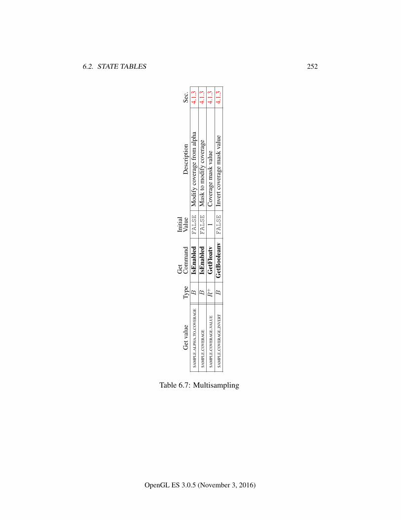
6.2. STATE TABLES 252
Get
valu
eTy
peG
etC
omm
and
Initi
alV
alue
Des
crip
tion
Sec.
SAM
PLE
AL
PHA
TOC
OV
ER
AG
EB
IsE
nabl
edFALSE
Mod
ify
cove
rage
from
alph
a4.
1.3
SAM
PLE
CO
VE
RA
GE
BIs
Ena
bled
FALSE
Mas
kto
mod
ify
cove
rage
4.1.
3SA
MPL
EC
OV
ER
AG
EVA
LU
ER
+G
etFl
oatv
1C
over
age
mas
kva
lue
4.1.
3SA
MPL
EC
OV
ER
AG
EIN
VE
RT
BG
etB
oole
anv
FALSE
Inve
rtco
vera
gem
ask
valu
e4.
1.3
Table 6.7: Multisampling
OpenGL ES 3.0.5 (November 3, 2016)
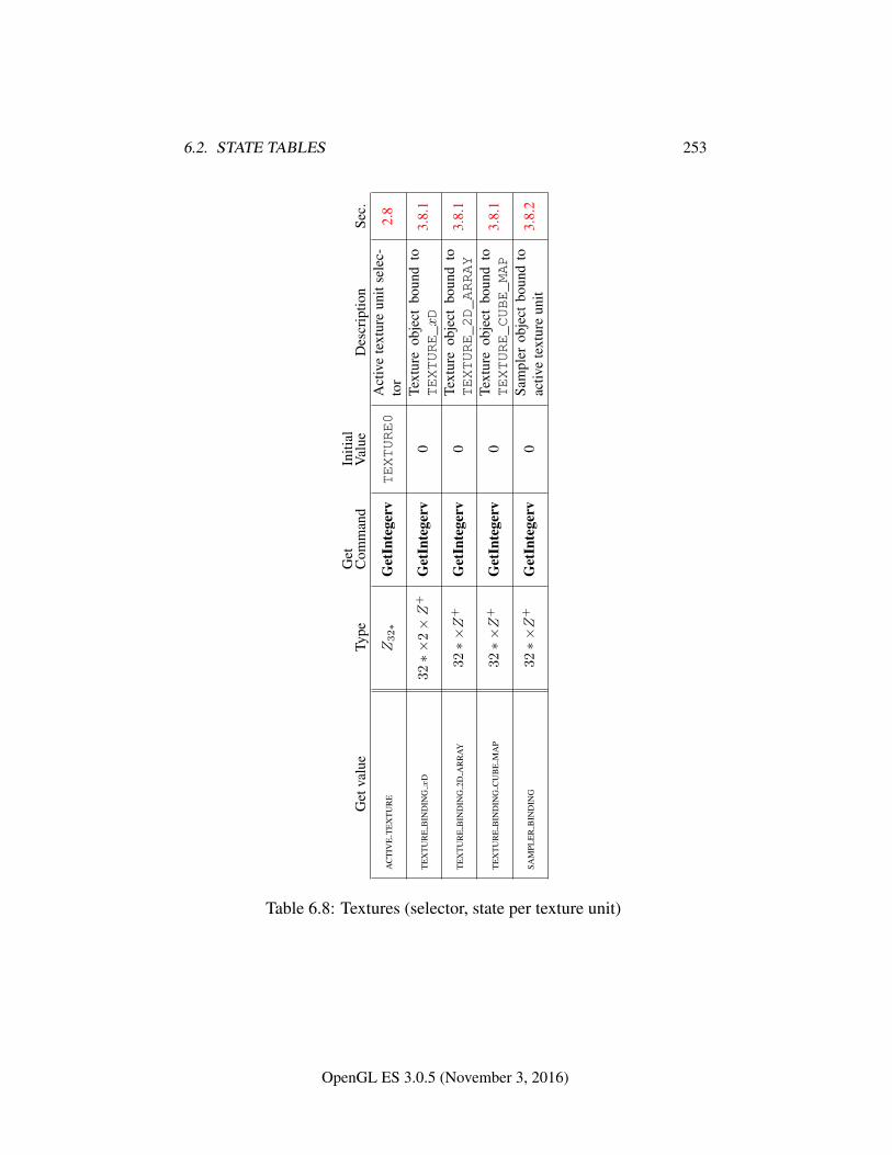
6.2. STATE TABLES 253
Get
valu
eTy
peG
etC
omm
and
Initi
alV
alue
Des
crip
tion
Sec.
AC
TIV
ET
EX
TU
RE
Z32∗
Get
Inte
gerv
TEXTURE0
Act
ive
text
ure
unit
sele
c-to
r2.
8
TE
XT
UR
EB
IND
ING
xD
32∗×
2×Z
+G
etIn
tege
rv0
Text
ure
obje
ctbo
und
toTEXTURE_xD
3.8.
1
TE
XT
UR
EB
IND
ING
2DA
RR
AY
32∗×Z
+G
etIn
tege
rv0
Text
ure
obje
ctbo
und
toTEXTURE_2D_ARRAY
3.8.
1
TE
XT
UR
EB
IND
ING
CU
BE
MA
P32∗×Z
+G
etIn
tege
rv0
Text
ure
obje
ctbo
und
toTEXTURE_CUBE_MAP
3.8.
1
SAM
PLE
RB
IND
ING
32∗×Z
+G
etIn
tege
rv0
Sam
pler
obje
ctbo
und
toac
tive
text
ure
unit
3.8.
2
Table 6.8: Textures (selector, state per texture unit)
OpenGL ES 3.0.5 (November 3, 2016)
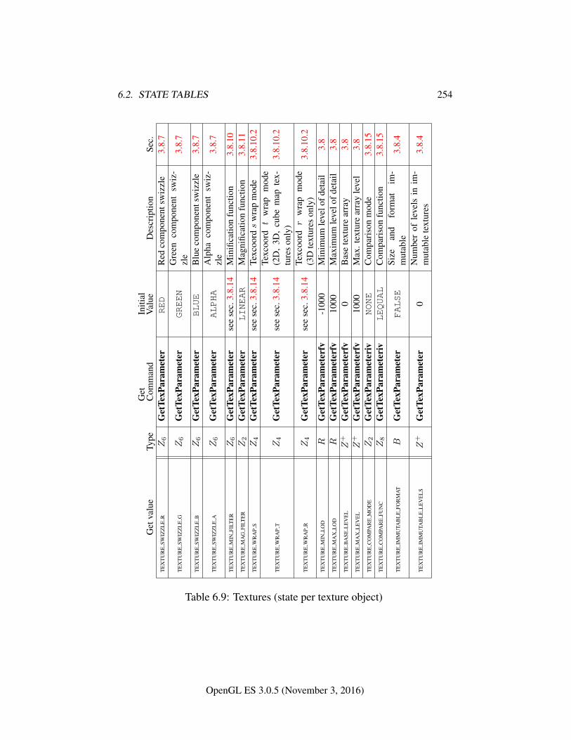
6.2. STATE TABLES 254
Get
valu
eTy
peG
etC
omm
and
Initi
alV
alue
Des
crip
tion
Sec.
TE
XT
UR
ESW
IZZ
LE
RZ6
Get
TexP
aram
eter
RED
Red
com
pone
ntsw
izzl
e3.
8.7
TE
XT
UR
ESW
IZZ
LE
GZ6
Get
TexP
aram
eter
GREEN
Gre
enco
mpo
nent
swiz
-zl
e3.
8.7
TE
XT
UR
ESW
IZZ
LE
BZ6
Get
TexP
aram
eter
BLUE
Blu
eco
mpo
nent
swiz
zle
3.8.
7
TE
XT
UR
ESW
IZZ
LE
AZ6
Get
TexP
aram
eter
ALPHA
Alp
haco
mpo
nent
swiz
-zl
e3.
8.7
TE
XT
UR
EM
INFI
LTE
RZ6
Get
TexP
aram
eter
see
sec.
3.8.
14M
inifi
catio
nfu
nctio
n3.
8.10
TE
XT
UR
EM
AG
FILT
ER
Z2
Get
TexP
aram
eter
LINEAR
Mag
nific
atio
nfu
nctio
n3.
8.11
TE
XT
UR
EW
RA
PS
Z4
Get
TexP
aram
eter
see
sec.
3.8.
14Te
xcoo
rds
wra
pm
ode
3.8.
10.2
TE
XT
UR
EW
RA
PT
Z4
Get
TexP
aram
eter
see
sec.
3.8.
14Te
xcoo
rdt
wra
pm
ode
(2D
,3D
,cu
bem
apte
x-tu
res
only
)3.
8.10
.2
TE
XT
UR
EW
RA
PR
Z4
Get
TexP
aram
eter
see
sec.
3.8.
14Te
xcoo
rdr
wra
pm
ode
(3D
text
ures
only
)3.
8.10
.2
TE
XT
UR
EM
INL
OD
RG
etTe
xPar
amet
erfv
-100
0M
inim
umle
velo
fdet
ail
3.8
TE
XT
UR
EM
AX
LO
DR
Get
TexP
aram
eter
fv10
00M
axim
umle
velo
fdet
ail
3.8
TE
XT
UR
EB
ASE
LE
VE
LZ
+G
etTe
xPar
amet
erfv
0B
ase
text
ure
arra
y3.
8T
EX
TU
RE
MA
XL
EV
EL
Z+
Get
TexP
aram
eter
fv10
00M
ax.t
extu
rear
ray
leve
l3.
8T
EX
TU
RE
CO
MPA
RE
MO
DE
Z2
Get
TexP
aram
eter
ivNONE
Com
pari
son
mod
e3.
8.15
TE
XT
UR
EC
OM
PAR
EFU
NC
Z8
Get
TexP
aram
eter
ivLEQUAL
Com
pari
son
func
tion
3.8.
15
TE
XT
UR
EIM
MU
TAB
LE
FOR
MA
TB
Get
TexP
aram
eter
FALSE
Size
and
form
atim
-m
utab
le3.
8.4
TE
XT
UR
EIM
MU
TAB
LE
LE
VE
LS
Z+
Get
TexP
aram
eter
0N
umbe
rof
leve
lsin
im-
mut
able
text
ures
3.8.
4
Table 6.9: Textures (state per texture object)
OpenGL ES 3.0.5 (November 3, 2016)
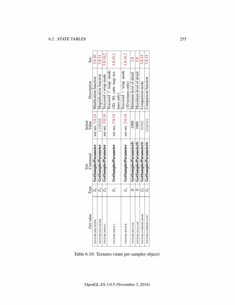
6.2. STATE TABLES 255
Get
valu
eTy
peG
etC
omm
and
Initi
alV
alue
Des
crip
tion
Sec.
TE
XT
UR
EM
INFI
LTE
RZ6
Get
Sam
pler
Para
met
erse
ese
c.3.
8.14
Min
ifica
tion
func
tion
3.8.
10T
EX
TU
RE
MA
GFI
LTE
RZ2
Get
Sam
pler
Para
met
erLINEAR
Mag
nific
atio
nfu
nctio
n3.
8.11
TE
XT
UR
EW
RA
PS
Z4
Get
Sam
pler
Para
met
erse
ese
c.3.
8.14
Texc
oords
wra
pm
ode
3.8.
10.2
TE
XT
UR
EW
RA
PT
Z4
Get
Sam
pler
Para
met
erse
ese
c.3.
8.14
Texc
oord
tw
rap
mod
e(2
D,
3D,
cube
map
tex-
ture
son
ly)
3.8.
10.2
TE
XT
UR
EW
RA
PR
Z4
Get
Sam
pler
Para
met
erse
ese
c.3.
8.14
Texc
oord
rw
rap
mod
e(3
Dte
xtur
eson
ly)
3.8.
10.2
TE
XT
UR
EM
INL
OD
RG
etSa
mpl
erPa
ram
eter
fv-1
000
Min
imum
leve
lofd
etai
l3.
8T
EX
TU
RE
MA
XL
OD
RG
etSa
mpl
erPa
ram
eter
fv10
00M
axim
umle
velo
fdet
ail
3.8
TE
XT
UR
EC
OM
PAR
EM
OD
EZ2
Get
Sam
pler
Para
met
eriv
NONE
Com
pari
son
mod
e3.
8.15
TE
XT
UR
EC
OM
PAR
EFU
NC
Z8
Get
Sam
pler
Para
met
eriv
LEQUAL
Com
pari
son
func
tion
3.8.
15
Table 6.10: Textures (state per sampler object)
OpenGL ES 3.0.5 (November 3, 2016)
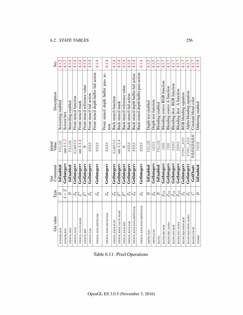
6.2. STATE TABLES 256
Get
valu
eTy
peG
etC
omm
and
Initi
alV
alue
Des
crip
tion
Sec.
SCIS
SOR
TE
STB
IsE
nabl
edFALSE
Scis
sori
ngen
able
d4.
1.2
SCIS
SOR
BO
X4×Z
Get
Inte
gerv
see
4.1.
2Sc
isso
rbox
4.1.
2ST
EN
CIL
TE
STB
IsE
nabl
edFALSE
Sten
cilin
gen
able
d4.
1.4
STE
NC
ILFU
NC
Z8
Get
Inte
gerv
ALWAYS
Fron
tste
ncil
func
tion
4.1.
4ST
EN
CIL
VAL
UE
MA
SKZ
+G
etIn
tege
rvse
e4.
1.4
Fron
tste
ncil
mas
k4.
1.4
STE
NC
ILR
EF
Z+
Get
Inte
gerv
0Fr
onts
tenc
ilre
fere
nce
valu
e4.
1.4
STE
NC
ILFA
ILZ8
Get
Inte
gerv
KEEP
Fron
tste
ncil
fail
actio
n4.
1.4
STE
NC
ILPA
SSD
EPT
HFA
ILZ8
Get
Inte
gerv
KEEP
Fron
tste
ncil
dept
hbu
ffer
fail
actio
n4.
1.4
STE
NC
ILPA
SSD
EPT
HPA
SSZ8
Get
Inte
gerv
KEEP
Fron
tst
enci
lde
pth
buff
erpa
ssac
-tio
n4.
1.4
STE
NC
ILB
AC
KFU
NC
Z8
Get
Inte
gerv
ALWAYS
Bac
kst
enci
lfun
ctio
n4.
1.4
STE
NC
ILB
AC
KVA
LU
EM
ASK
Z+
Get
Inte
gerv
see
4.1.
4B
ack
sten
cilm
ask
4.1.
4ST
EN
CIL
BA
CK
RE
FZ
+G
etIn
tege
rv0
Bac
kst
enci
lref
eren
ceva
lue
4.1.
4ST
EN
CIL
BA
CK
FAIL
Z8
Get
Inte
gerv
KEEP
Bac
kst
enci
lfai
lact
ion
4.1.
4ST
EN
CIL
BA
CK
PASS
DE
PTH
FAIL
Z8
Get
Inte
gerv
KEEP
Bac
kst
enci
ldep
thbu
ffer
fail
actio
n4.
1.4
STE
NC
ILB
AC
KPA
SSD
EPT
HPA
SSZ8
Get
Inte
gerv
KEEP
Bac
kst
enci
ldep
thbu
ffer
pass
actio
n4.
1.4
DE
PTH
TE
STB
IsE
nabl
edFALSE
Dep
thte
sten
able
d4.
1.5
DE
PTH
FUN
CZ8
Get
Inte
gerv
LESS
Dep
thte
stfu
nctio
n4.
1.5
BL
EN
DB
IsE
nabl
edFALSE
Ble
ndin
gen
able
d4.
1.7
BL
EN
DSR
CR
GB
Z19
Get
Inte
gerv
ONE
Ble
ndin
gso
urce
RG
Bfu
nctio
n4.
1.7
BL
EN
DSR
CA
LPH
AZ19
Get
Inte
gerv
ONE
Ble
ndin
gso
urce
Afu
nctio
n4.
1.7
BL
EN
DD
STR
GB
Z19
Get
Inte
gerv
ZERO
Ble
ndin
gde
st.R
GB
func
tion
4.1.
7B
LE
ND
DST
AL
PHA
Z19
Get
Inte
gerv
ZERO
Ble
ndin
gde
st.A
func
tion
4.1.
7B
LE
ND
EQ
UA
TIO
NR
GB
Z5
Get
Inte
gerv
FUNC_ADD
RG
Bbl
endi
ngeq
uatio
n4.
1.7
BL
EN
DE
QU
AT
ION
AL
PHA
Z5
Get
Inte
gerv
FUNC_ADD
Alp
habl
endi
ngeq
uatio
n4.
1.7
BL
EN
DC
OL
OR
CG
etFl
oatv
0.0,
0.0,
0.0,
0.0
Con
stan
tble
ndco
lor
4.1.
7D
ITH
ER
BIs
Ena
bled
TRUE
Dith
erin
gen
able
d4.
1.9
Table 6.11: Pixel Operations
OpenGL ES 3.0.5 (November 3, 2016)
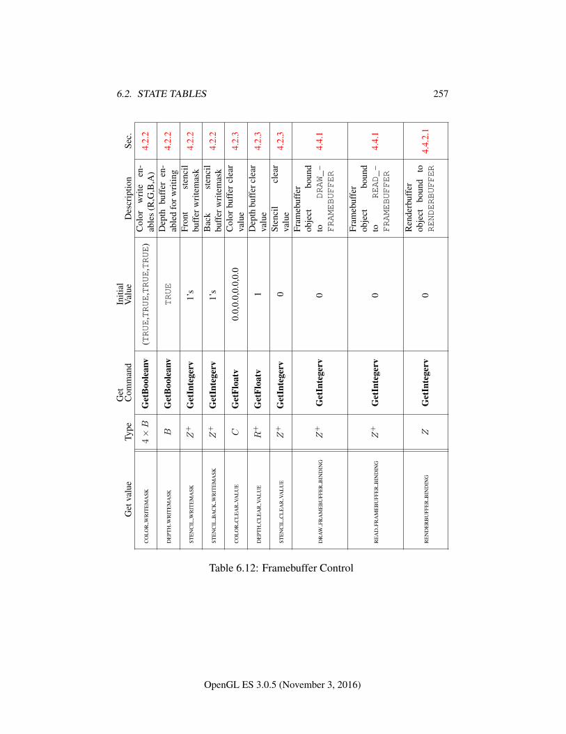
6.2. STATE TABLES 257
Get
valu
eTy
peG
etC
omm
and
Initi
alV
alue
Des
crip
tion
Sec.
CO
LO
RW
RIT
EM
ASK
4×B
Get
Boo
lean
v(TRUE
,TRUE
,TRUE
,TRUE
)C
olor
wri
teen
-ab
les
(R,G
,B,A
)4.
2.2
DE
PTH
WR
ITE
MA
SKB
Get
Boo
lean
vTRUE
Dep
thbu
ffer
en-
able
dfo
rwri
ting
4.2.
2
STE
NC
ILW
RIT
EM
ASK
Z+
Get
Inte
gerv
1’s
Fron
tst
enci
lbu
ffer
wri
tem
ask
4.2.
2
STE
NC
ILB
AC
KW
RIT
EM
ASK
Z+
Get
Inte
gerv
1’s
Bac
kst
enci
lbu
ffer
wri
tem
ask
4.2.
2
CO
LO
RC
LE
AR
VAL
UE
CG
etFl
oatv
0.0,
0.0,
0.0,
0.0
Col
orbu
ffer
clea
rva
lue
4.2.
3
DE
PTH
CL
EA
RVA
LU
ER
+G
etFl
oatv
1D
epth
buff
ercl
ear
valu
e4.
2.3
STE
NC
ILC
LE
AR
VAL
UE
Z+
Get
Inte
gerv
0St
enci
lcl
ear
valu
e4.
2.3
DR
AW
FRA
ME
BU
FFE
RB
IND
ING
Z+
Get
Inte
gerv
0
Fram
ebuf
fer
obje
ctbo
und
toDRAW_-
FRAMEBUFFER
4.4.
1
RE
AD
FRA
ME
BU
FFE
RB
IND
ING
Z+
Get
Inte
gerv
0
Fram
ebuf
fer
obje
ctbo
und
toREAD_-
FRAMEBUFFER
4.4.
1
RE
ND
ER
BU
FFE
RB
IND
ING
ZG
etIn
tege
rv0
Ren
derb
uffe
rob
ject
boun
dto
RENDERBUFFER
4.4.
2.1
Table 6.12: Framebuffer Control
OpenGL ES 3.0.5 (November 3, 2016)
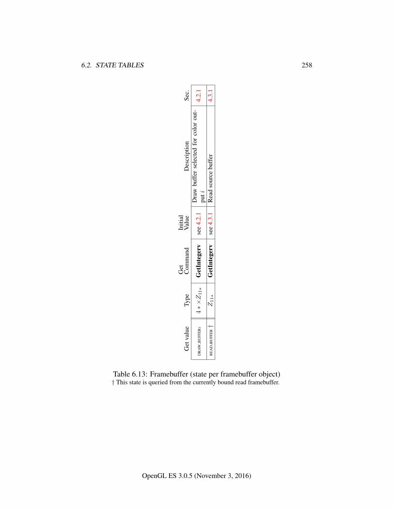
6.2. STATE TABLES 258
Get
valu
eTy
peG
etC
omm
and
Initi
alV
alue
Des
crip
tion
Sec.
DR
AW
BU
FFE
Ri
4∗×Z11∗
Get
Inte
gerv
see
4.2.
1D
raw
buff
erse
lect
edfo
rco
lor
out-
puti
4.2.
1
RE
AD
BU
FFE
R†
Z11∗
Get
Inte
gerv
see
4.3.
1R
ead
sour
cebu
ffer
4.3.
1
Table 6.13: Framebuffer (state per framebuffer object)† This state is queried from the currently bound read framebuffer.
OpenGL ES 3.0.5 (November 3, 2016)
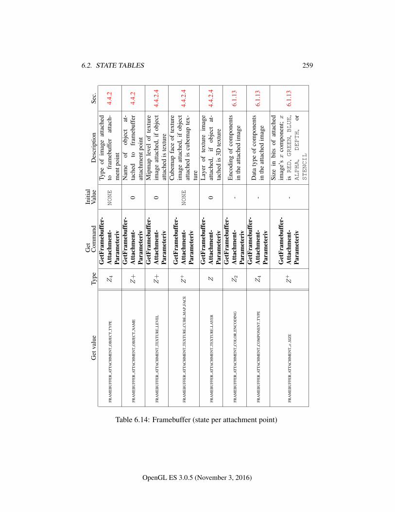
6.2. STATE TABLES 259
Get
valu
eTy
peG
etC
omm
and
Initi
alV
alue
Des
crip
tion
Sec.
FRA
ME
BU
FFE
RA
TTA
CH
ME
NT
OB
JEC
TT
YPE
Z4
Get
Fram
ebuf
fer-
Att
achm
ent-
Para
met
eriv
NONE
Type
ofim
age
atta
ched
tofr
ameb
uffe
rat
tach
-m
entp
oint
4.4.
2
FRA
ME
BU
FFE
RA
TTA
CH
ME
NT
OB
JEC
TN
AM
EZ
+G
etFr
ameb
uffe
r-A
ttac
hmen
t-Pa
ram
eter
iv0
Nam
eof
obje
ctat
-ta
ched
tofr
ameb
uffe
rat
tach
men
tpoi
nt4.
4.2
FRA
ME
BU
FFE
RA
TTA
CH
ME
NT
TE
XT
UR
EL
EV
EL
Z+
Get
Fram
ebuf
fer-
Att
achm
ent-
Para
met
eriv
0M
ipm
aple
vel
ofte
xtur
eim
age
atta
ched
,if
obje
ctat
tach
edis
text
ure
4.4.
2.4
FRA
ME
BU
FFE
RA
TTA
CH
ME
NT
TE
XT
UR
EC
UB
EM
AP
FAC
EZ
+G
etFr
ameb
uffe
r-A
ttac
hmen
t-Pa
ram
eter
ivNONE
Cub
emap
face
ofte
xtur
eim
age
atta
ched
,if
obje
ctat
tach
edis
cube
map
tex-
ture
4.4.
2.4
FRA
ME
BU
FFE
RA
TTA
CH
ME
NT
TE
XT
UR
EL
AY
ER
ZG
etFr
ameb
uffe
r-A
ttac
hmen
t-Pa
ram
eter
iv0
Lay
erof
text
ure
imag
eat
tach
ed,
ifob
ject
at-
tach
edis
3Dte
xtur
e4.
4.2.
4
FRA
ME
BU
FFE
RA
TTA
CH
ME
NT
CO
LO
RE
NC
OD
ING
Z2
Get
Fram
ebuf
fer-
Att
achm
ent-
Para
met
eriv
-E
ncod
ing
ofco
mpo
nent
sin
the
atta
ched
imag
e6.
1.13
FRA
ME
BU
FFE
RA
TTA
CH
ME
NT
CO
MPO
NE
NT
TY
PEZ4
Get
Fram
ebuf
fer-
Att
achm
ent-
Para
met
eriv
-D
ata
type
ofco
mpo
nent
sin
the
atta
ched
imag
e6.
1.13
FRA
ME
BU
FFE
RA
TTA
CH
ME
NTx
SIZ
EZ
+G
etFr
ameb
uffe
r-A
ttac
hmen
t-Pa
ram
eter
iv-
Size
inbi
tsof
atta
ched
imag
e’sx
com
pone
nt;x
isRED
,GREEN
,BLUE
,ALPHA
,DEPTH
,or
STENCIL
6.1.
13
Table 6.14: Framebuffer (state per attachment point)
OpenGL ES 3.0.5 (November 3, 2016)
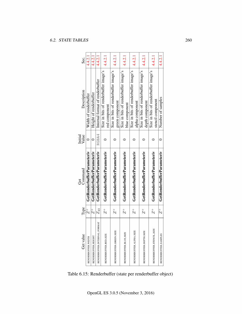
6.2. STATE TABLES 260
Get
valu
eTy
peG
etC
omm
and
Initi
alV
alue
Des
crip
tion
Sec.
RE
ND
ER
BU
FFE
RW
IDT
HZ
+G
etR
ende
rbuf
ferP
aram
eter
iv0
Wid
thof
rend
erbu
ffer
4.4.
2.1
RE
ND
ER
BU
FFE
RH
EIG
HT
Z+
Get
Ren
derb
uffe
rPar
amet
eriv
0H
eigh
tofr
ende
rbuf
fer
4.4.
2.1
RE
ND
ER
BU
FFE
RIN
TE
RN
AL
FOR
MA
TZ43
Get
Ren
derb
uffe
rPar
amet
eriv
RGBA4
Inte
rnal
form
atof
rend
erbu
ffer
4.4.
2.1
RE
ND
ER
BU
FFE
RR
ED
SIZ
EZ
+G
etR
ende
rbuf
ferP
aram
eter
iv0
Size
inbi
tsof
rend
erbu
ffer
imag
e’s
red
com
pone
nt4.
4.2.
1
RE
ND
ER
BU
FFE
RG
RE
EN
SIZ
EZ
+G
etR
ende
rbuf
ferP
aram
eter
iv0
Size
inbi
tsof
rend
erbu
ffer
imag
e’s
gree
nco
mpo
nent
4.4.
2.1
RE
ND
ER
BU
FFE
RB
LU
ESI
ZE
Z+
Get
Ren
derb
uffe
rPar
amet
eriv
0Si
zein
bits
ofre
nder
buff
erim
age’
sbl
ueco
mpo
nent
4.4.
2.1
RE
ND
ER
BU
FFE
RA
LPH
ASI
ZE
Z+
Get
Ren
derb
uffe
rPar
amet
eriv
0Si
zein
bits
ofre
nder
buff
erim
age’
sal
pha
com
pone
nt4.
4.2.
1
RE
ND
ER
BU
FFE
RD
EPT
HSI
ZE
Z+
Get
Ren
derb
uffe
rPar
amet
eriv
0Si
zein
bits
ofre
nder
buff
erim
age’
sde
pth
com
pone
nt4.
4.2.
1
RE
ND
ER
BU
FFE
RST
EN
CIL
SIZ
EZ
+G
etR
ende
rbuf
ferP
aram
eter
iv0
Size
inbi
tsof
rend
erbu
ffer
imag
e’s
sten
cilc
ompo
nent
4.4.
2.1
RE
ND
ER
BU
FFE
RSA
MPL
ES
Z+
Get
Ren
derb
uffe
rPar
amet
eriv
0N
umbe
rofs
ampl
es4.
4.2.
1
Table 6.15: Renderbuffer (state per renderbuffer object)
OpenGL ES 3.0.5 (November 3, 2016)
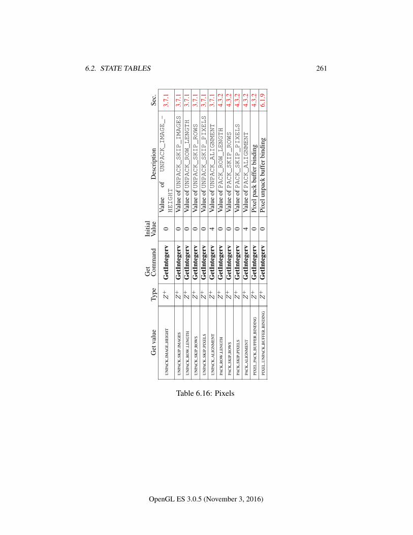
6.2. STATE TABLES 261
Get
valu
eTy
peG
etC
omm
and
Initi
alV
alue
Des
crip
tion
Sec.
UN
PAC
KIM
AG
EH
EIG
HT
Z+
Get
Inte
gerv
0V
alue
ofUNPACK_IMAGE_-
HEIGHT
3.7.
1
UN
PAC
KSK
IPIM
AG
ES
Z+
Get
Inte
gerv
0V
alue
ofUNPACK_SKIP_IMAGES
3.7.
1U
NPA
CK
RO
WL
EN
GT
HZ
+G
etIn
tege
rv0
Val
ueofUNPACK_ROW_LENGTH
3.7.
1U
NPA
CK
SKIP
RO
WS
Z+
Get
Inte
gerv
0V
alue
ofUNPACK_SKIP_ROWS
3.7.
1U
NPA
CK
SKIP
PIX
EL
SZ
+G
etIn
tege
rv0
Val
ueofUNPACK_SKIP_PIXELS
3.7.
1U
NPA
CK
AL
IGN
ME
NT
Z+
Get
Inte
gerv
4V
alue
ofUNPACK_ALIGNMENT
3.7.
1PA
CK
RO
WL
EN
GT
HZ
+G
etIn
tege
rv0
Val
ueofPACK_ROW_LENGTH
4.3.
2PA
CK
SKIP
RO
WS
Z+
Get
Inte
gerv
0V
alue
ofPACK_SKIP_ROWS
4.3.
2PA
CK
SKIP
PIX
EL
SZ
+G
etIn
tege
rv0
Val
ueofPACK_SKIP_PIXELS
4.3.
2PA
CK
AL
IGN
ME
NT
Z+
Get
Inte
gerv
4V
alue
ofPACK_ALIGNMENT
4.3.
2PI
XE
LPA
CK
BU
FFE
RB
IND
ING
Z+
Get
Inte
gerv
0Pi
xelp
ack
buff
erbi
ndin
g4.
3.2
PIX
EL
UN
PAC
KB
UFF
ER
BIN
DIN
GZ
+G
etIn
tege
rv0
Pixe
lunp
ack
buff
erbi
ndin
g6.
1.9
Table 6.16: Pixels
OpenGL ES 3.0.5 (November 3, 2016)
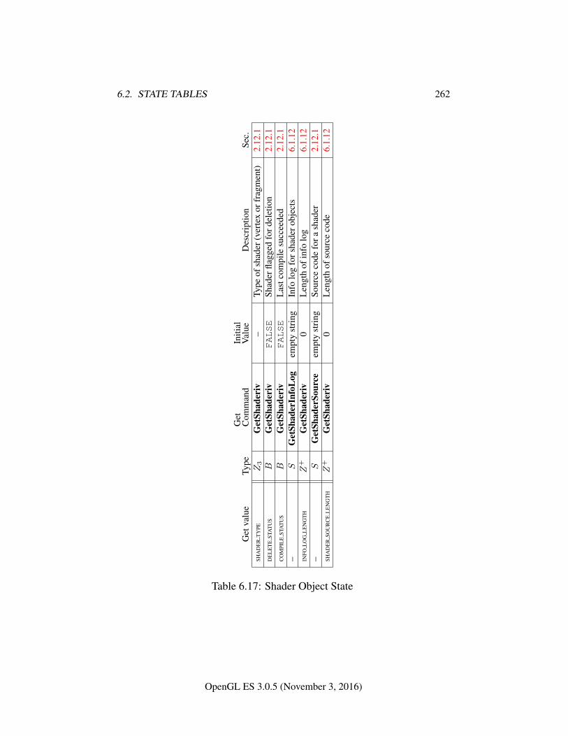
6.2. STATE TABLES 262
Get
valu
eTy
peG
etC
omm
and
Initi
alV
alue
Des
crip
tion
Sec.
SHA
DE
RT
YPE
Z3
Get
Shad
eriv
–Ty
peof
shad
er(v
erte
xor
frag
men
t)2.
12.1
DE
LE
TE
STA
TU
SB
Get
Shad
eriv
FALSE
Shad
erfla
gged
ford
elet
ion
2.12
.1C
OM
PIL
EST
AT
US
BG
etSh
ader
ivFALSE
Las
tcom
pile
succ
eede
d2.
12.1
–S
Get
Shad
erIn
foL
ogem
pty
stri
ngIn
folo
gfo
rsha
dero
bjec
ts6.
1.12
INFO
LO
GL
EN
GT
HZ
+G
etSh
ader
iv0
Len
gth
ofin
folo
g6.
1.12
–S
Get
Shad
erSo
urce
empt
yst
ring
Sour
ceco
defo
rash
ader
2.12
.1SH
AD
ER
SOU
RC
EL
EN
GT
HZ
+G
etSh
ader
iv0
Len
gth
ofso
urce
code
6.1.
12
Table 6.17: Shader Object State
OpenGL ES 3.0.5 (November 3, 2016)
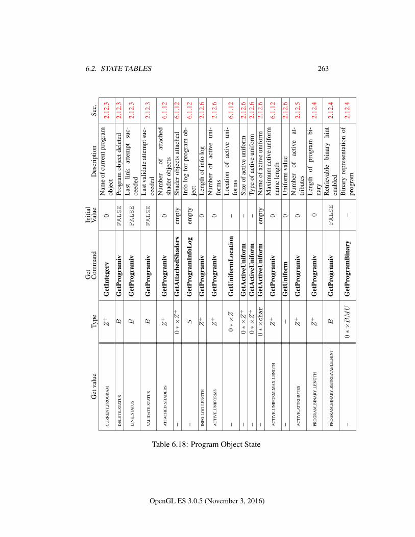
6.2. STATE TABLES 263
Get
valu
eTy
peG
etC
omm
and
Initi
alV
alue
Des
crip
tion
Sec.
CU
RR
EN
TPR
OG
RA
MZ
+G
etIn
tege
rv0
Nam
eof
curr
entp
rogr
amob
ject
2.12
.3
DE
LE
TE
STA
TU
SB
Get
Prog
ram
ivFALSE
Prog
ram
obje
ctde
lete
d2.
12.3
LIN
KST
AT
US
BG
etPr
ogra
miv
FALSE
Las
tlin
kat
tem
ptsu
c-ce
eded
2.12
.3
VAL
IDA
TE
STA
TU
SB
Get
Prog
ram
ivFALSE
Las
tval
idat
eat
tem
ptsu
c-ce
eded
2.12
.3
AT
TAC
HE
DSH
AD
ER
SZ
+G
etPr
ogra
miv
0N
umbe
rof
atta
ched
shad
erob
ject
s6.
1.12
–0∗×Z
+G
etA
ttac
hedS
hade
rsem
pty
Shad
erob
ject
sat
tach
ed6.
1.12
–S
Get
Prog
ram
Info
Log
empt
yIn
folo
gfo
rpr
ogra
mob
-je
ct6.
1.12
INFO
LO
GL
EN
GT
HZ
+G
etPr
ogra
miv
0L
engt
hof
info
log
2.12
.6
AC
TIV
EU
NIF
OR
MS
Z+
Get
Prog
ram
iv0
Num
ber
ofac
tive
uni-
form
s2.
12.6
–0∗×Z
Get
Uni
form
Loc
atio
n–
Loc
atio
nof
activ
eun
i-fo
rms
6.1.
12
–0∗×Z
+G
etA
ctiv
eUni
form
–Si
zeof
activ
eun
ifor
m2.
12.6
–0∗×Z
+G
etA
ctiv
eUni
form
–Ty
peof
activ
eun
ifor
m2.
12.6
–0∗×char
Get
Act
iveU
nifo
rmem
pty
Nam
eof
activ
eun
ifor
m2.
12.6
AC
TIV
EU
NIF
OR
MM
AX
LE
NG
TH
Z+
Get
Prog
ram
iv0
Max
imum
activ
eun
ifor
mna
me
leng
th6.
1.12
–−
Get
Uni
form
0U
nifo
rmva
lue
2.12
.6
AC
TIV
EA
TT
RIB
UT
ES
Z+
Get
Prog
ram
iv0
Num
ber
ofac
tive
at-
trib
utes
2.12
.5
PRO
GR
AM
BIN
ARY
LE
NG
TH
Z+
Get
Prog
ram
iv0
Len
gth
ofpr
ogra
mbi
-na
ry2.
12.4
PRO
GR
AM
BIN
ARY
RE
TR
IEVA
BL
EH
INT
BG
etPr
ogra
miv
FALSE
Ret
riev
able
bina
ryhi
nten
able
d2.
12.4
–0∗×BMU
Get
Prog
ram
Bin
ary
–B
inar
yre
pres
enta
tion
ofpr
ogra
m2.
12.4
Table 6.18: Program Object State
OpenGL ES 3.0.5 (November 3, 2016)
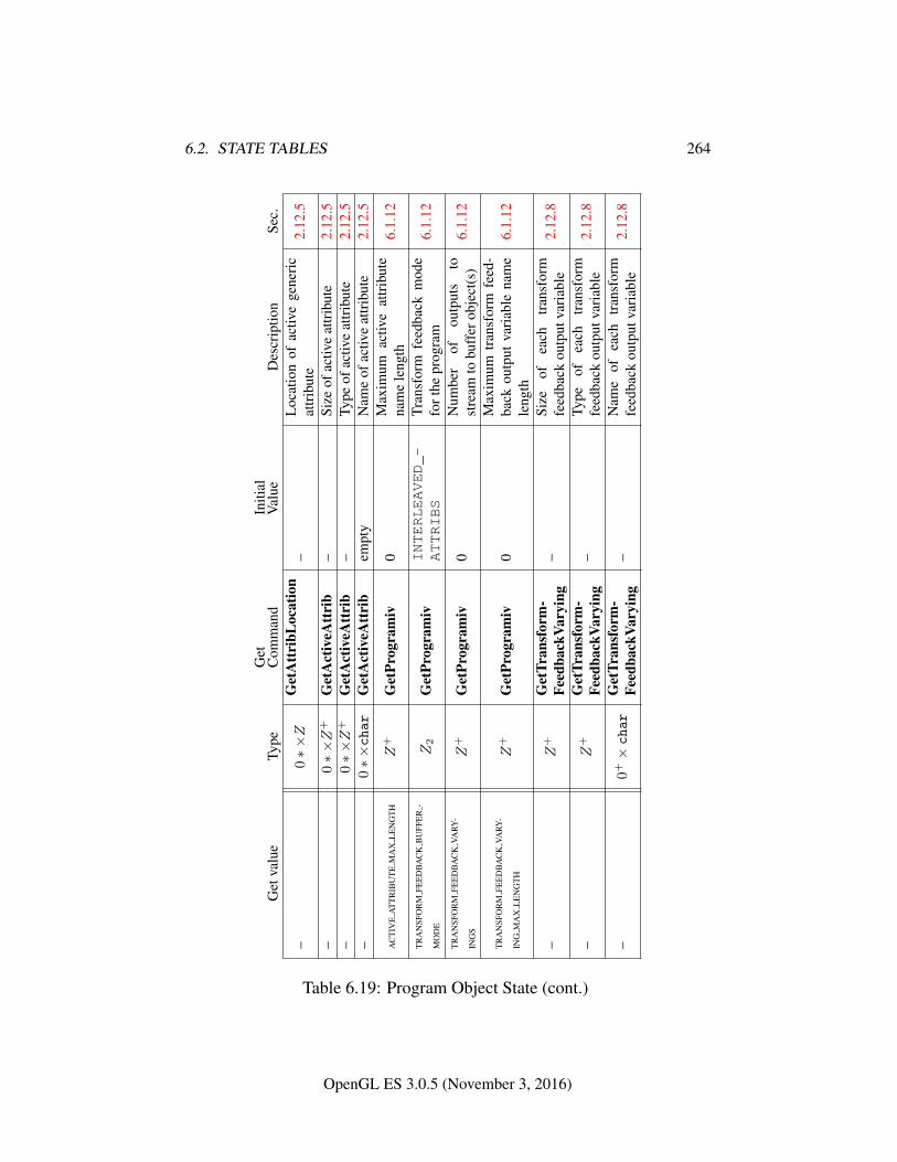
6.2. STATE TABLES 264
Get
valu
eTy
peG
etC
omm
and
Initi
alV
alue
Des
crip
tion
Sec.
–0∗×Z
Get
Att
ribL
ocat
ion
–L
ocat
ion
ofac
tive
gene
ric
attr
ibut
e2.
12.5
–0∗×Z
+G
etA
ctiv
eAtt
rib
–Si
zeof
activ
eat
trib
ute
2.12
.5–
0∗×Z
+G
etA
ctiv
eAtt
rib
–Ty
peof
activ
eat
trib
ute
2.12
.5–
0∗×char
Get
Act
iveA
ttri
bem
pty
Nam
eof
activ
eat
trib
ute
2.12
.5
AC
TIV
EA
TT
RIB
UT
EM
AX
LE
NG
TH
Z+
Get
Prog
ram
iv0
Max
imum
activ
eat
trib
ute
nam
ele
ngth
6.1.
12
TR
AN
SFO
RM
FEE
DB
AC
KB
UFF
ER
-
MO
DE
Z2
Get
Prog
ram
ivINTERLEAVED_-
ATTRIBS
Tran
sfor
mfe
edba
ckm
ode
fort
hepr
ogra
m6.
1.12
TR
AN
SFO
RM
FEE
DB
AC
KVA
RY-
ING
SZ
+G
etPr
ogra
miv
0N
umbe
rof
outp
uts
tost
ream
tobu
ffer
obje
ct(s
)6.
1.12
TR
AN
SFO
RM
FEE
DB
AC
KVA
RY-
ING
MA
XL
EN
GT
HZ
+G
etPr
ogra
miv
0M
axim
umtr
ansf
orm
feed
-ba
ckou
tput
vari
able
nam
ele
ngth
6.1.
12
–Z
+G
etTr
ansf
orm
-Fe
edba
ckVa
ryin
g–
Size
ofea
chtr
ansf
orm
feed
back
outp
utva
riab
le2.
12.8
–Z
+G
etTr
ansf
orm
-Fe
edba
ckVa
ryin
g–
Type
ofea
chtr
ansf
orm
feed
back
outp
utva
riab
le2.
12.8
–0+×char
Get
Tran
sfor
m-
Feed
back
Vary
ing
–N
ame
ofea
chtr
ansf
orm
feed
back
outp
utva
riab
le2.
12.8
Table 6.19: Program Object State (cont.)
OpenGL ES 3.0.5 (November 3, 2016)
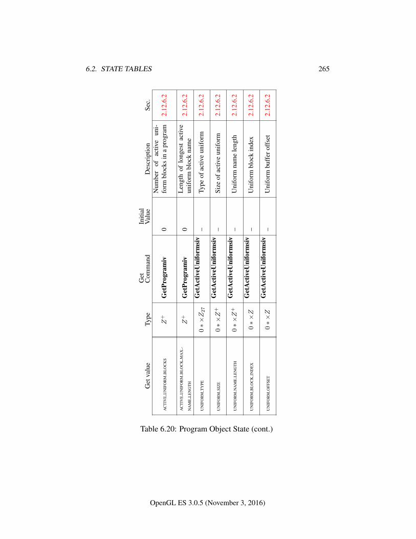
6.2. STATE TABLES 265
Get
valu
eTy
peG
etC
omm
and
Initi
alV
alue
Des
crip
tion
Sec.
AC
TIV
EU
NIF
OR
MB
LO
CK
SZ
+G
etPr
ogra
miv
0N
umbe
rof
activ
eun
i-fo
rmbl
ocks
ina
prog
ram
2.12
.6.2
AC
TIV
EU
NIF
OR
MB
LO
CK
MA
X-
NA
ME
LE
NG
TH
Z+
Get
Prog
ram
iv0
Len
gth
oflo
nges
tac
tive
unif
orm
bloc
kna
me
2.12
.6.2
UN
IFO
RM
TY
PE0∗×Z27
Get
Act
iveU
nifo
rmsi
v–
Type
ofac
tive
unif
orm
2.12
.6.2
UN
IFO
RM
SIZ
E0∗×Z
+G
etA
ctiv
eUni
form
siv
–Si
zeof
activ
eun
ifor
m2.
12.6
.2
UN
IFO
RM
NA
ME
LE
NG
TH
0∗×Z
+G
etA
ctiv
eUni
form
siv
–U
nifo
rmna
me
leng
th2.
12.6
.2
UN
IFO
RM
BL
OC
KIN
DE
X0∗×Z
Get
Act
iveU
nifo
rmsi
v–
Uni
form
bloc
kin
dex
2.12
.6.2
UN
IFO
RM
OFF
SET
0∗×Z
Get
Act
iveU
nifo
rmsi
v–
Uni
form
buff
erof
fset
2.12
.6.2
Table 6.20: Program Object State (cont.)
OpenGL ES 3.0.5 (November 3, 2016)
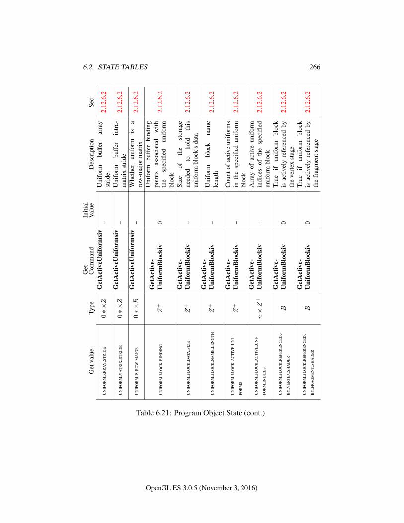
6.2. STATE TABLES 266
Get
valu
eTy
peG
etC
omm
and
Initi
alV
alue
Des
crip
tion
Sec.
UN
IFO
RM
AR
RA
YST
RID
E0∗×Z
Get
Act
iveU
nifo
rmsi
v–
Uni
form
buff
erar
ray
stri
de2.
12.6
.2
UN
IFO
RM
MA
TR
IXST
RID
E0∗×Z
Get
Act
iveU
nifo
rmsi
v–
Uni
form
buff
erin
tra-
mat
rix
stri
de2.
12.6
.2
UN
IFO
RM
ISR
OW
MA
JOR
0∗×B
Get
Act
iveU
nifo
rmsi
v–
Whe
ther
unif
orm
isa
row
-maj
orm
atri
x2.
12.6
.2
UN
IFO
RM
BL
OC
KB
IND
ING
Z+
Get
Act
ive-
Uni
form
Blo
ckiv
0
Uni
form
buff
erbi
ndin
gpo
ints
asso
ciat
edw
ithth
esp
ecifi
edun
ifor
mbl
ock
2.12
.6.2
UN
IFO
RM
BL
OC
KD
ATA
SIZ
EZ
+G
etA
ctiv
e-U
nifo
rmB
lock
iv–
Size
ofth
est
orag
ene
eded
toho
ldth
isun
ifor
mbl
ock’
sda
ta2.
12.6
.2
UN
IFO
RM
BL
OC
KN
AM
EL
EN
GT
HZ
+G
etA
ctiv
e-U
nifo
rmB
lock
iv–
Uni
form
bloc
kna
me
leng
th2.
12.6
.2
UN
IFO
RM
BL
OC
KA
CT
IVE
UN
I-
FOR
MS
Z+
Get
Act
ive-
Uni
form
Blo
ckiv
–C
ount
ofac
tive
unif
orm
sin
the
spec
ified
unif
orm
bloc
k2.
12.6
.2
UN
IFO
RM
BL
OC
KA
CT
IVE
UN
I-
FOR
MIN
DIC
ES
n×Z
+G
etA
ctiv
e-U
nifo
rmB
lock
iv–
Arr
ayof
activ
eun
ifor
min
dice
sof
the
spec
ified
unif
orm
bloc
k2.
12.6
.2
UN
IFO
RM
BL
OC
KR
EFE
RE
NC
ED
-
BY
VE
RT
EX
SHA
DE
RB
Get
Act
ive-
Uni
form
Blo
ckiv
0Tr
ueif
unif
orm
bloc
kis
activ
ely
refe
renc
edby
the
vert
exst
age
2.12
.6.2
UN
IFO
RM
BL
OC
KR
EFE
RE
NC
ED
-
BY
FRA
GM
EN
TSH
AD
ER
BG
etA
ctiv
e-U
nifo
rmB
lock
iv0
True
ifun
ifor
mbl
ock
isac
tivel
yre
fere
nced
byth
efr
agm
ents
tage
2.12
.6.2
Table 6.21: Program Object State (cont.)
OpenGL ES 3.0.5 (November 3, 2016)
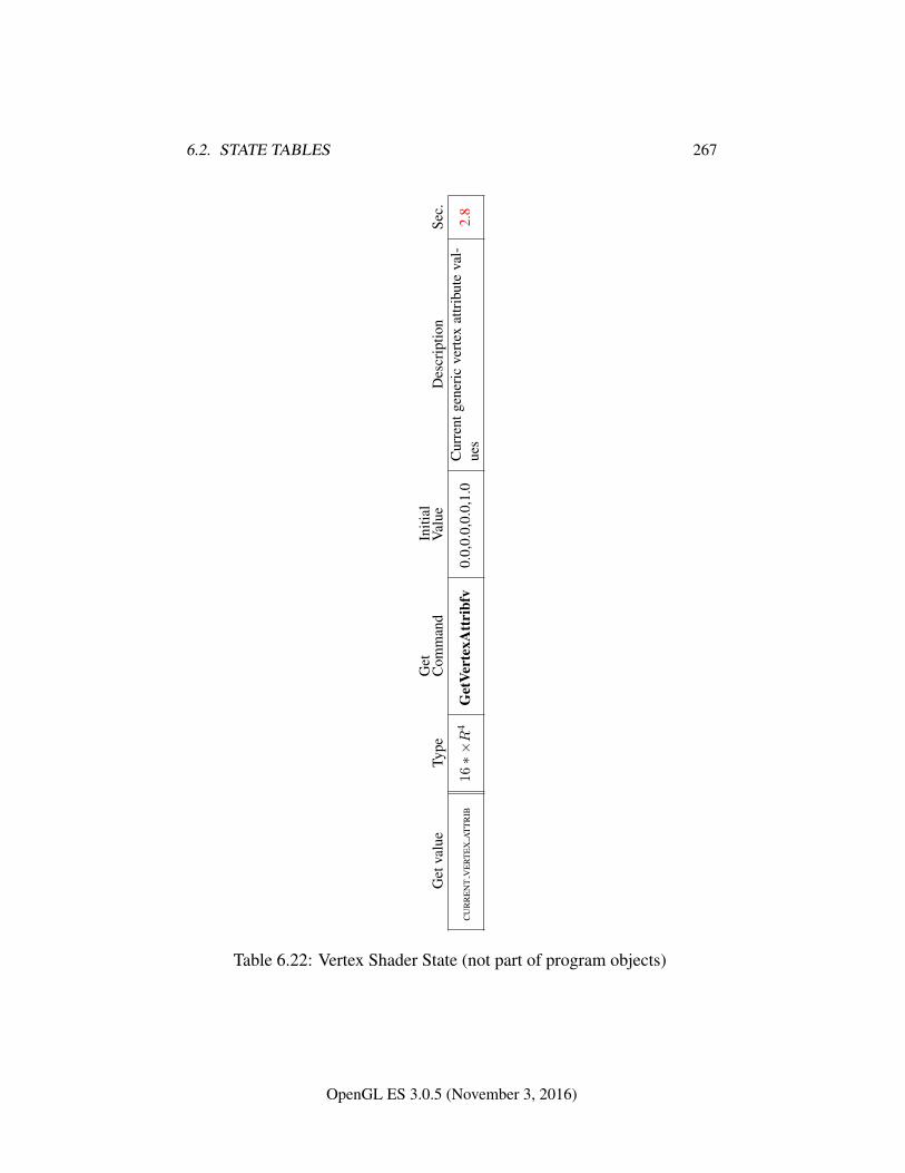
6.2. STATE TABLES 267
Get
valu
eTy
peG
etC
omm
and
Initi
alV
alue
Des
crip
tion
Sec.
CU
RR
EN
TV
ER
TE
XA
TT
RIB
16∗×R
4G
etVe
rtex
Att
ribf
v0.
0,0.
0,0.
0,1.
0C
urre
ntge
neri
cve
rtex
attr
ibut
eva
l-ue
s2.
8
Table 6.22: Vertex Shader State (not part of program objects)
OpenGL ES 3.0.5 (November 3, 2016)
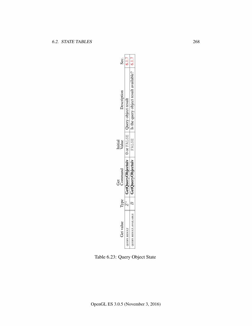
6.2. STATE TABLES 268
Get
valu
eTy
peG
etC
omm
and
Initi
alV
alue
Des
crip
tion
Sec.
QU
ERY
RE
SULT
Z+
Get
Que
ryO
bjec
tuiv
0orFALSE
Que
ryob
ject
resu
lt6.
1.7
QU
ERY
RE
SULT
AVA
ILA
BL
EB
Get
Que
ryO
bjec
tuiv
FALSE
Isth
equ
ery
obje
ctre
sult
avai
labl
e?6.
1.7
Table 6.23: Query Object State
OpenGL ES 3.0.5 (November 3, 2016)
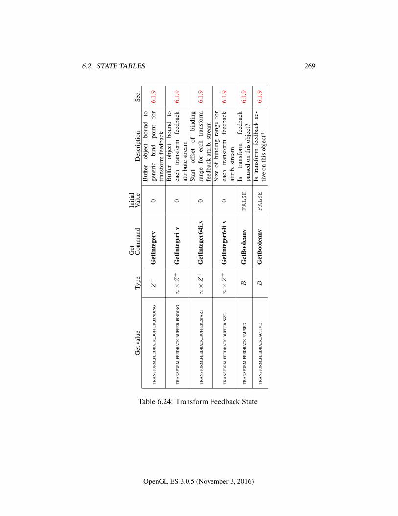
6.2. STATE TABLES 269
Get
valu
eTy
peG
etC
omm
and
Initi
alV
alue
Des
crip
tion
Sec.
TR
AN
SFO
RM
FEE
DB
AC
KB
UFF
ER
BIN
DIN
GZ
+G
etIn
tege
rv0
Buf
fer
obje
ctbo
und
toge
neri
cbi
ndpo
int
for
tran
sfor
mfe
edba
ck6.
1.9
TR
AN
SFO
RM
FEE
DB
AC
KB
UFF
ER
BIN
DIN
Gn×Z
+G
etIn
tege
riv
0B
uffe
rob
ject
boun
dto
each
tran
sfor
mfe
edba
ckat
trib
ute
stre
am6.
1.9
TR
AN
SFO
RM
FEE
DB
AC
KB
UFF
ER
STA
RT
n×Z
+G
etIn
tege
r64i
v0
Star
tof
fset
ofbi
ndin
gra
nge
for
each
tran
sfor
mfe
edba
ckat
trib
.str
eam
6.1.
9
TR
AN
SFO
RM
FEE
DB
AC
KB
UFF
ER
SIZ
En×Z
+G
etIn
tege
r64i
v0
Size
ofbi
ndin
gra
nge
for
each
tran
sfor
mfe
edba
ckat
trib
.str
eam
6.1.
9
TR
AN
SFO
RM
FEE
DB
AC
KPA
USE
DB
Get
Boo
lean
vFALSE
Istr
ansf
orm
feed
back
paus
edon
this
obje
ct?
6.1.
9
TR
AN
SFO
RM
FEE
DB
AC
KA
CT
IVE
BG
etB
oole
anv
FALSE
Istr
ansf
orm
feed
back
ac-
tive
onth
isob
ject
?6.
1.9
Table 6.24: Transform Feedback State
OpenGL ES 3.0.5 (November 3, 2016)
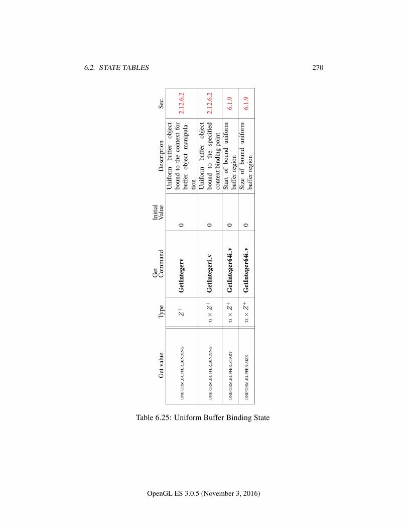
6.2. STATE TABLES 270
Get
valu
eTy
peG
etC
omm
and
Initi
alV
alue
Des
crip
tion
Sec.
UN
IFO
RM
BU
FFE
RB
IND
ING
Z+
Get
Inte
gerv
0
Uni
form
buff
erob
ject
boun
dto
the
cont
ext
for
buff
erob
ject
man
ipul
a-tio
n
2.12
.6.2
UN
IFO
RM
BU
FFE
RB
IND
ING
n×Z
+G
etIn
tege
riv
0U
nifo
rmbu
ffer
obje
ctbo
und
toth
esp
ecifi
edco
ntex
tbin
ding
poin
t2.
12.6
.2
UN
IFO
RM
BU
FFE
RST
AR
Tn×Z
+G
etIn
tege
r64i
v0
Star
tof
boun
dun
ifor
mbu
ffer
regi
on6.
1.9
UN
IFO
RM
BU
FFE
RSI
ZE
n×Z
+G
etIn
tege
r64i
v0
Size
ofbo
und
unif
orm
buff
erre
gion
6.1.
9
Table 6.25: Uniform Buffer Binding State
OpenGL ES 3.0.5 (November 3, 2016)
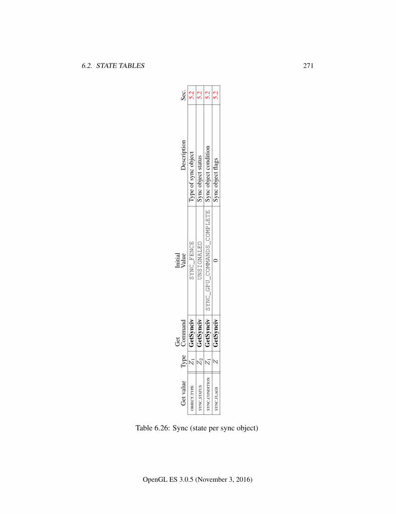
6.2. STATE TABLES 271
Get
valu
eTy
peG
etC
omm
and
Initi
alV
alue
Des
crip
tion
Sec.
OB
JEC
TT
YPE
Z1
Get
Sync
ivSYNC_FENCE
Type
ofsy
ncob
ject
5.2
SYN
CST
AT
US
Z2
Get
Sync
ivUNSIGNALED
Sync
obje
ctst
atus
5.2
SYN
CC
ON
DIT
ION
Z1
Get
Sync
ivSYNC_GPU_COMMANDS_COMPLETE
Sync
obje
ctco
nditi
on5.
2SY
NC
FLA
GS
ZG
etSy
nciv
0Sy
ncob
ject
flags
5.2
Table 6.26: Sync (state per sync object)
OpenGL ES 3.0.5 (November 3, 2016)
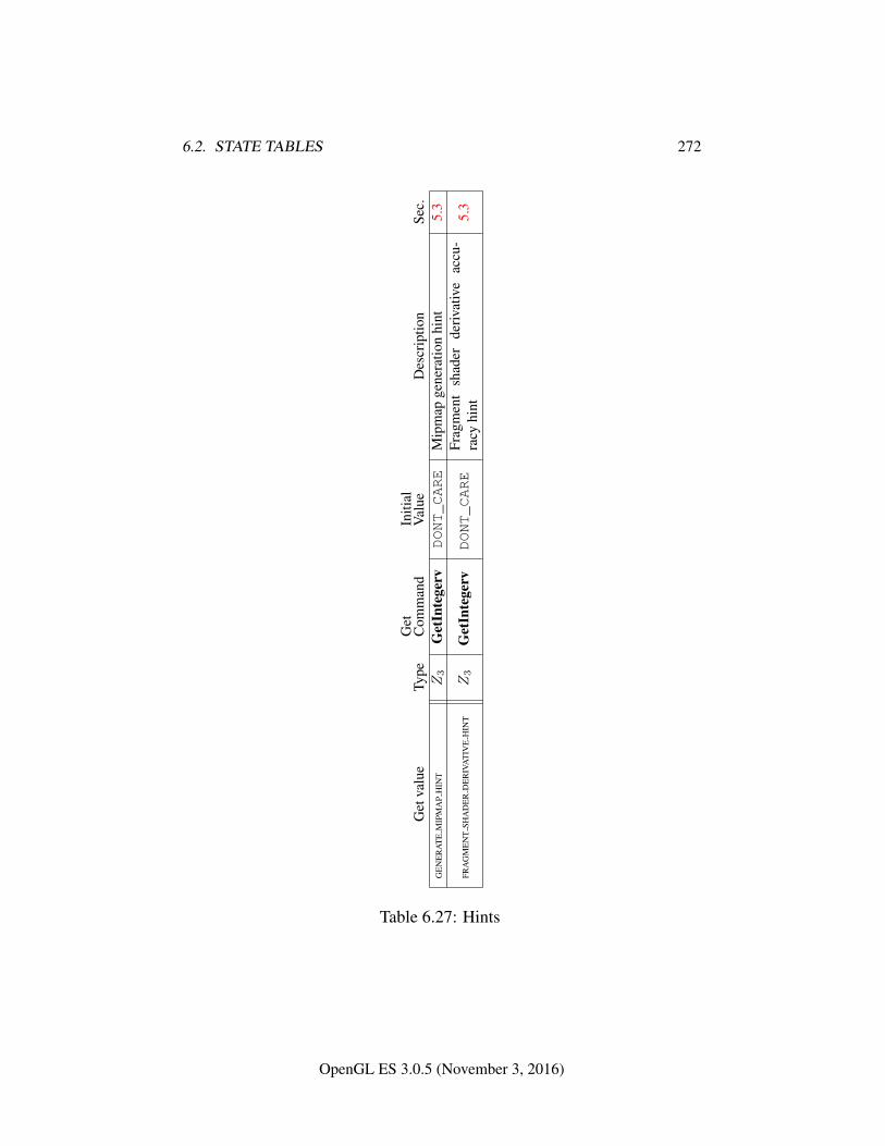
6.2. STATE TABLES 272
Get
valu
eTy
peG
etC
omm
and
Initi
alV
alue
Des
crip
tion
Sec.
GE
NE
RA
TE
MIP
MA
PH
INT
Z3
Get
Inte
gerv
DONT_CARE
Mip
map
gene
ratio
nhi
nt5.
3
FRA
GM
EN
TSH
AD
ER
DE
RIV
AT
IVE
HIN
TZ3
Get
Inte
gerv
DONT_CARE
Frag
men
tsh
ader
deriv
ativ
eac
cu-
racy
hint
5.3
Table 6.27: Hints
OpenGL ES 3.0.5 (November 3, 2016)
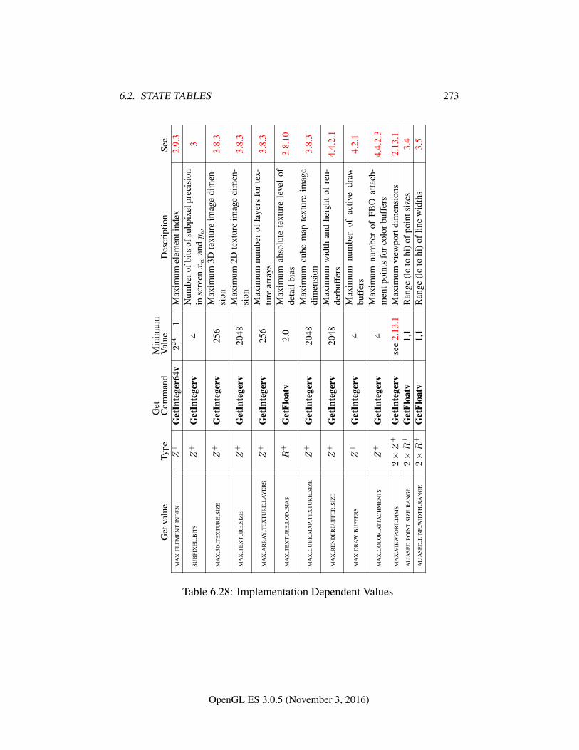
6.2. STATE TABLES 273
Get
valu
eTy
peG
etC
omm
and
Min
imum
Val
ueD
escr
iptio
nSe
c.M
AX
EL
EM
EN
TIN
DE
XZ
+G
etIn
tege
r64v
224−
1M
axim
umel
emen
tind
ex2.
9.3
SUB
PIX
EL
BIT
SZ
+G
etIn
tege
rv4
Num
bero
fbits
ofsu
bpix
elpr
ecis
ion
insc
reenxw
andy w
3
MA
X3D
TE
XT
UR
ESI
ZE
Z+
Get
Inte
gerv
256
Max
imum
3Dte
xtur
eim
age
dim
en-
sion
3.8.
3
MA
XT
EX
TU
RE
SIZ
EZ
+G
etIn
tege
rv20
48M
axim
um2D
text
ure
imag
edi
men
-si
on3.
8.3
MA
XA
RR
AY
TE
XT
UR
EL
AY
ER
SZ
+G
etIn
tege
rv25
6M
axim
umnu
mbe
rofl
ayer
sfo
rtex
-tu
rear
rays
3.8.
3
MA
XT
EX
TU
RE
LO
DB
IAS
R+
Get
Floa
tv2.
0M
axim
umab
solu
tete
xtur
ele
vel
ofde
tail
bias
3.8.
10
MA
XC
UB
EM
AP
TE
XT
UR
ESI
ZE
Z+
Get
Inte
gerv
2048
Max
imum
cube
map
text
ure
imag
edi
men
sion
3.8.
3
MA
XR
EN
DE
RB
UFF
ER
SIZ
EZ
+G
etIn
tege
rv20
48M
axim
umw
idth
and
heig
htof
ren-
derb
uffe
rs4.
4.2.
1
MA
XD
RA
WB
UFF
ER
SZ
+G
etIn
tege
rv4
Max
imum
num
ber
ofac
tive
draw
buff
ers
4.2.
1
MA
XC
OL
OR
AT
TAC
HM
EN
TS
Z+
Get
Inte
gerv
4M
axim
umnu
mbe
rof
FBO
atta
ch-
men
tpoi
nts
forc
olor
buff
ers
4.4.
2.3
MA
XV
IEW
POR
TD
IMS
2×Z
+G
etIn
tege
rvse
e2.
13.1
Max
imum
view
port
dim
ensi
ons
2.13
.1A
LIA
SED
POIN
TSI
ZE
RA
NG
E2×R
+G
etFl
oatv
1,1
Ran
ge(l
oto
hi)o
fpoi
ntsi
zes
3.4
AL
IASE
DL
INE
WID
TH
RA
NG
E2×R
+G
etFl
oatv
1,1
Ran
ge(l
oto
hi)o
flin
ew
idth
s3.
5
Table 6.28: Implementation Dependent Values
OpenGL ES 3.0.5 (November 3, 2016)
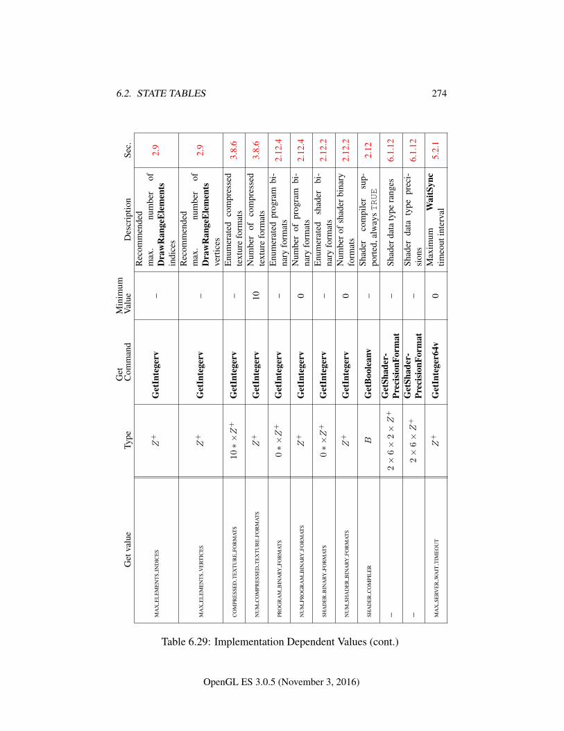
6.2. STATE TABLES 274
Get
valu
eTy
peG
etC
omm
and
Min
imum
Val
ueD
escr
iptio
nSe
c.
MA
XE
LE
ME
NT
SIN
DIC
ES
Z+
Get
Inte
gerv
–
Rec
omm
ende
dm
ax.
num
ber
ofD
raw
Ran
geE
lem
ents
indi
ces
2.9
MA
XE
LE
ME
NT
SV
ER
TIC
ES
Z+
Get
Inte
gerv
–
Rec
omm
ende
dm
ax.
num
ber
ofD
raw
Ran
geE
lem
ents
vert
ices
2.9
CO
MPR
ESS
ED
TE
XT
UR
EFO
RM
AT
S10∗×Z
+G
etIn
tege
rv–
Enu
mer
ated
com
pres
sed
text
ure
form
ats
3.8.
6
NU
MC
OM
PRE
SSE
DT
EX
TU
RE
FOR
MA
TS
Z+
Get
Inte
gerv
10N
umbe
rof
com
pres
sed
text
ure
form
ats
3.8.
6
PRO
GR
AM
BIN
ARY
FOR
MA
TS
0∗×Z
+G
etIn
tege
rv–
Enu
mer
ated
prog
ram
bi-
nary
form
ats
2.12
.4
NU
MPR
OG
RA
MB
INA
RYFO
RM
AT
SZ
+G
etIn
tege
rv0
Num
ber
ofpr
ogra
mbi
-na
ryfo
rmat
s2.
12.4
SHA
DE
RB
INA
RYFO
RM
AT
S0∗×Z
+G
etIn
tege
rv–
Enu
mer
ated
shad
erbi
-na
ryfo
rmat
s2.
12.2
NU
MSH
AD
ER
BIN
ARY
FOR
MA
TS
Z+
Get
Inte
gerv
0N
umbe
rof
shad
erbi
nary
form
ats
2.12
.2
SHA
DE
RC
OM
PIL
ER
BG
etB
oole
anv
–Sh
ader
com
pile
rsu
p-po
rted
,alw
aysTRUE
2.12
–2×
6×
2×Z
+G
etSh
ader
-Pr
ecis
ionF
orm
at–
Shad
erda
taty
pera
nges
6.1.
12
–2×
6×Z
+G
etSh
ader
-Pr
ecis
ionF
orm
at–
Shad
erda
taty
pepr
eci-
sion
s6.
1.12
MA
XSE
RVE
RW
AIT
TIM
EO
UT
Z+
Get
Inte
ger6
4v0
Max
imum
Wai
tSyn
ctim
eout
inte
rval
5.2.
1
Table 6.29: Implementation Dependent Values (cont.)
OpenGL ES 3.0.5 (November 3, 2016)
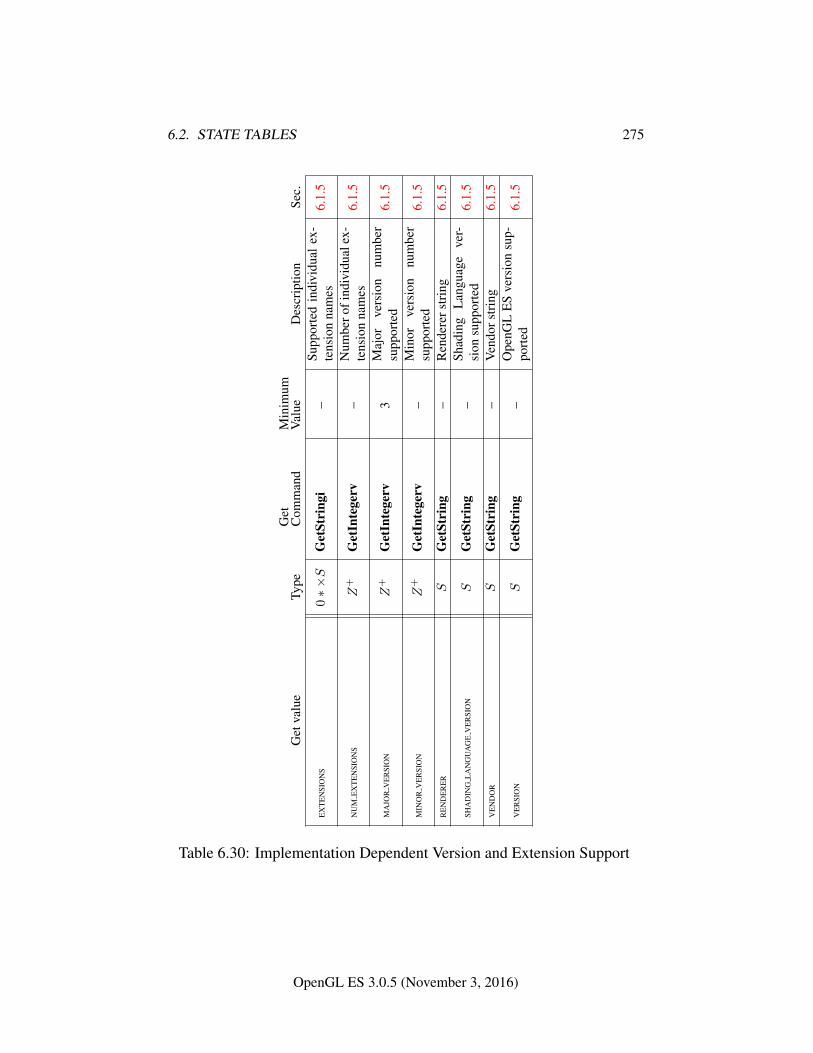
6.2. STATE TABLES 275
Get
valu
eTy
peG
etC
omm
and
Min
imum
Val
ueD
escr
iptio
nSe
c.
EX
TE
NSI
ON
S0∗×S
Get
Stri
ngi
–Su
ppor
ted
indi
vidu
alex
-te
nsio
nna
mes
6.1.
5
NU
ME
XT
EN
SIO
NS
Z+
Get
Inte
gerv
–N
umbe
rofi
ndiv
idua
lex-
tens
ion
nam
es6.
1.5
MA
JOR
VE
RSI
ON
Z+
Get
Inte
gerv
3M
ajor
vers
ion
num
ber
supp
orte
d6.
1.5
MIN
OR
VE
RSI
ON
Z+
Get
Inte
gerv
–M
inor
vers
ion
num
ber
supp
orte
d6.
1.5
RE
ND
ER
ER
SG
etSt
ring
–R
ende
rers
trin
g6.
1.5
SHA
DIN
GL
AN
GU
AG
EV
ER
SIO
NS
Get
Stri
ng–
Shad
ing
Lan
guag
eve
r-si
onsu
ppor
ted
6.1.
5
VE
ND
OR
SG
etSt
ring
–V
endo
rstr
ing
6.1.
5
VE
RSI
ON
SG
etSt
ring
–O
penG
LE
Sve
rsio
nsu
p-po
rted
6.1.
5
Table 6.30: Implementation Dependent Version and Extension Support
OpenGL ES 3.0.5 (November 3, 2016)
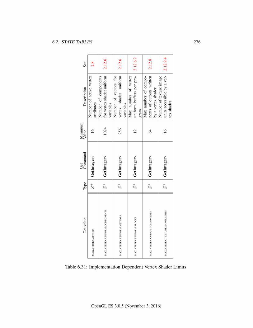
6.2. STATE TABLES 276
Get
valu
eTy
peG
etC
omm
and
Min
imum
Val
ueD
escr
iptio
nSe
c.
MA
XV
ER
TE
XA
TT
RIB
SZ
+G
etIn
tege
rv16
Num
ber
ofac
tive
vert
exat
trib
utes
2.8
MA
XV
ER
TE
XU
NIF
OR
MC
OM
PON
EN
TS
Z+
Get
Inte
gerv
1024
Num
ber
ofco
mpo
nent
sfo
rver
tex
shad
erun
ifor
mva
riab
les
2.12
.6
MA
XV
ER
TE
XU
NIF
OR
MV
EC
TOR
SZ
+G
etIn
tege
rv25
6N
umbe
rof
vect
ors
for
vert
exsh
ader
unif
orm
vari
able
s2.
12.6
MA
XV
ER
TE
XU
NIF
OR
MB
LO
CK
SZ
+G
etIn
tege
rv12
Max
num
ber
ofve
rtex
unif
orm
buff
ers
per
pro-
gram
2.12
.6.2
MA
XV
ER
TE
XO
UT
PUT
CO
MPO
NE
NT
SZ
+G
etIn
tege
rv64
Max
num
ber
ofco
mpo
-ne
nts
ofou
tput
sw
ritte
nby
ave
rtex
shad
er2.
12.8
MA
XV
ER
TE
XT
EX
TU
RE
IMA
GE
UN
ITS
Z+
Get
Inte
gerv
16N
umbe
roft
extu
reim
age
units
acce
ssib
leby
ave
r-te
xsh
ader
2.12
.9.4
Table 6.31: Implementation Dependent Vertex Shader Limits
OpenGL ES 3.0.5 (November 3, 2016)
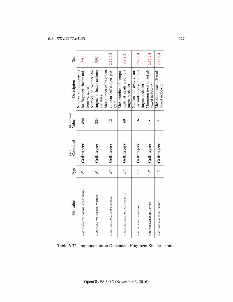
6.2. STATE TABLES 277
Get
valu
eTy
peG
etC
omm
and
Min
imum
Val
ueD
escr
iptio
nSe
c.
MA
XFR
AG
ME
NT
UN
IFO
RM
CO
MPO
NE
NT
SZ
+G
etIn
tege
rv89
6N
umbe
rof
com
pone
nts
for
frag
men
tsh
ader
uni-
form
vari
able
s3.
9.1
MA
XFR
AG
ME
NT
UN
IFO
RM
VE
CTO
RS
Z+
Get
Inte
gerv
224
Num
ber
ofve
ctor
sfo
rfr
agm
ent
shad
erun
ifor
mva
riab
les
3.9.
1
MA
XFR
AG
ME
NT
UN
IFO
RM
BL
OC
KS
Z+
Get
Inte
gerv
12M
axnu
mbe
roff
ragm
ent
unif
orm
buff
ers
per
pro-
gram
2.12
.6.2
MA
XFR
AG
ME
NT
INPU
TC
OM
PON
EN
TS
Z+
Get
Inte
gerv
60M
axnu
mbe
rof
com
po-
nent
sof
inpu
tsre
adby
afr
agm
ents
hade
r3.
9.2.
2
MA
XT
EX
TU
RE
IMA
GE
UN
ITS
Z+
Get
Inte
gerv
16N
umbe
rof
text
ure
im-
age
units
acce
ssib
leby
afr
agm
ents
hade
r2.
12.9
.4
MIN
PRO
GR
AM
TE
XE
LO
FFSE
TZ
Get
Inte
gerv
-8M
inim
umte
xelo
ffse
tal-
low
edin
look
up2.
12.9
.4
MA
XPR
OG
RA
MT
EX
EL
OFF
SET
ZG
etIn
tege
rv7
Max
imum
texe
loff
seta
l-lo
wed
inlo
okup
2.12
.9.4
Table 6.32: Implementation Dependent Fragment Shader Limits
OpenGL ES 3.0.5 (November 3, 2016)
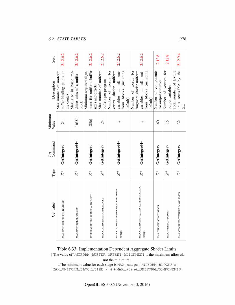
6.2. STATE TABLES 278
Get
valu
eTy
peG
etC
omm
and
Min
imum
Val
ueD
escr
iptio
nSe
c.
MA
XU
NIF
OR
MB
UFF
ER
BIN
DIN
GS
Z+
Get
Inte
gerv
24M
axnu
mbe
rof
unif
orm
buff
erbi
ndin
gpo
ints
onth
eco
ntex
t2.
12.6
.2
MA
XU
NIF
OR
MB
LO
CK
SIZ
EZ
+G
etIn
tege
r64v
1638
4M
axsi
zein
basi
cm
a-ch
ine
units
ofa
unif
orm
bloc
k2.
12.6
.2
UN
IFO
RM
BU
FFE
RO
FFSE
TA
LIG
NM
EN
TZ
+G
etIn
tege
rv25
6†M
inim
umre
quir
edal
ign-
men
tfo
run
ifor
mbu
ffer
size
san
dof
fset
s2.
12.6
.2
MA
XC
OM
BIN
ED
UN
IFO
RM
BL
OC
KS
Z+
Get
Inte
gerv
24M
axnu
mbe
rof
unif
orm
buff
ers
perp
rogr
am2.
12.6
.2
MA
XC
OM
BIN
ED
VE
RT
EX
UN
IFO
RM
CO
MPO
-
NE
NT
SZ
+G
etIn
tege
r64v
‡
Num
ber
ofw
ords
for
vert
exsh
ader
unif
orm
vari
able
sin
all
uni-
form
bloc
ks(i
nclu
ding
defa
ult)
2.12
.6.2
MA
XC
OM
BIN
ED
FRA
GM
EN
TU
NIF
OR
MC
OM
PO-
NE
NT
SZ
+G
etIn
tege
r64v
‡
Num
ber
ofw
ords
for
frag
men
tsh
ader
unif
orm
vari
able
sin
all
uni-
form
bloc
ks(i
nclu
ding
defa
ult)
2.12
.6.2
MA
XVA
RYIN
GC
OM
PON
EN
TS
Z+
Get
Inte
gerv
60N
umbe
rof
com
pone
nts
foro
utpu
tvar
iabl
es2.
12.8
MA
XVA
RYIN
GV
EC
TOR
SZ
+G
etIn
tege
rv15
Num
ber
ofve
ctor
sfo
rou
tput
vari
able
s2.
12.8
MA
XC
OM
BIN
ED
TE
XT
UR
EIM
AG
EU
NIT
SZ
+G
etIn
tege
rv32
Tota
lnu
mbe
rof
text
ure
units
acce
ssib
leby
the
GL
2.12
.9.4
Table 6.33: Implementation Dependent Aggregate Shader Limits† The value of UNIFORM_BUFFER_OFFSET_ALIGNMENT is the maximum allowed,
not the minimum.‡The minimum value for each stage is MAX_stage_UNIFORM_BLOCKS ×
MAX_UNIFORM_BLOCK_SIZE / 4 + MAX_stage_UNIFORM_COMPONENTS
OpenGL ES 3.0.5 (November 3, 2016)
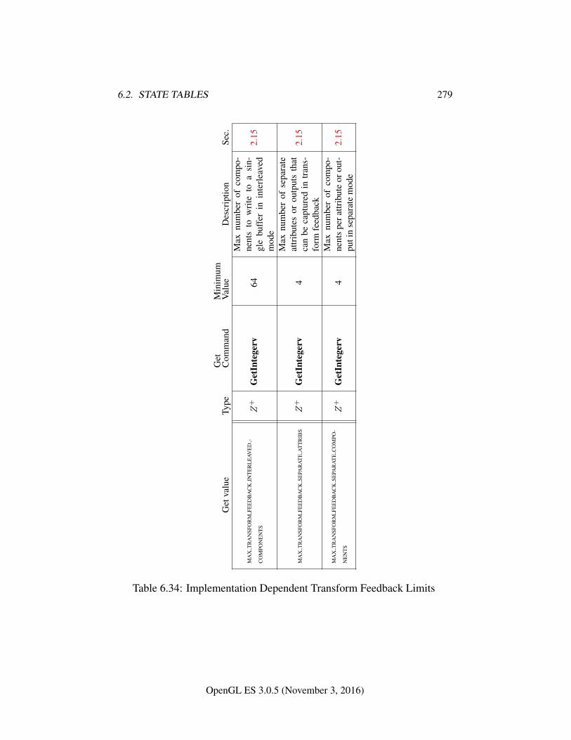
6.2. STATE TABLES 279
Get
valu
eTy
peG
etC
omm
and
Min
imum
Val
ueD
escr
iptio
nSe
c.
MA
XT
RA
NSF
OR
MFE
ED
BA
CK
INT
ER
LE
AVE
D-
CO
MPO
NE
NT
SZ
+G
etIn
tege
rv64
Max
num
ber
ofco
mpo
-ne
nts
tow
rite
toa
sin-
gle
buff
erin
inte
rlea
ved
mod
e
2.15
MA
XT
RA
NSF
OR
MFE
ED
BA
CK
SEPA
RA
TE
AT
TR
IBS
Z+
Get
Inte
gerv
4
Max
num
ber
ofse
para
teat
trib
utes
orou
tput
sth
atca
nbe
capt
ured
intr
ans-
form
feed
back
2.15
MA
XT
RA
NSF
OR
MFE
ED
BA
CK
SEPA
RA
TE
CO
MPO
-
NE
NT
SZ
+G
etIn
tege
rv4
Max
num
ber
ofco
mpo
-ne
nts
pera
ttrib
ute
orou
t-pu
tin
sepa
rate
mod
e2.
15
Table 6.34: Implementation Dependent Transform Feedback Limits
OpenGL ES 3.0.5 (November 3, 2016)
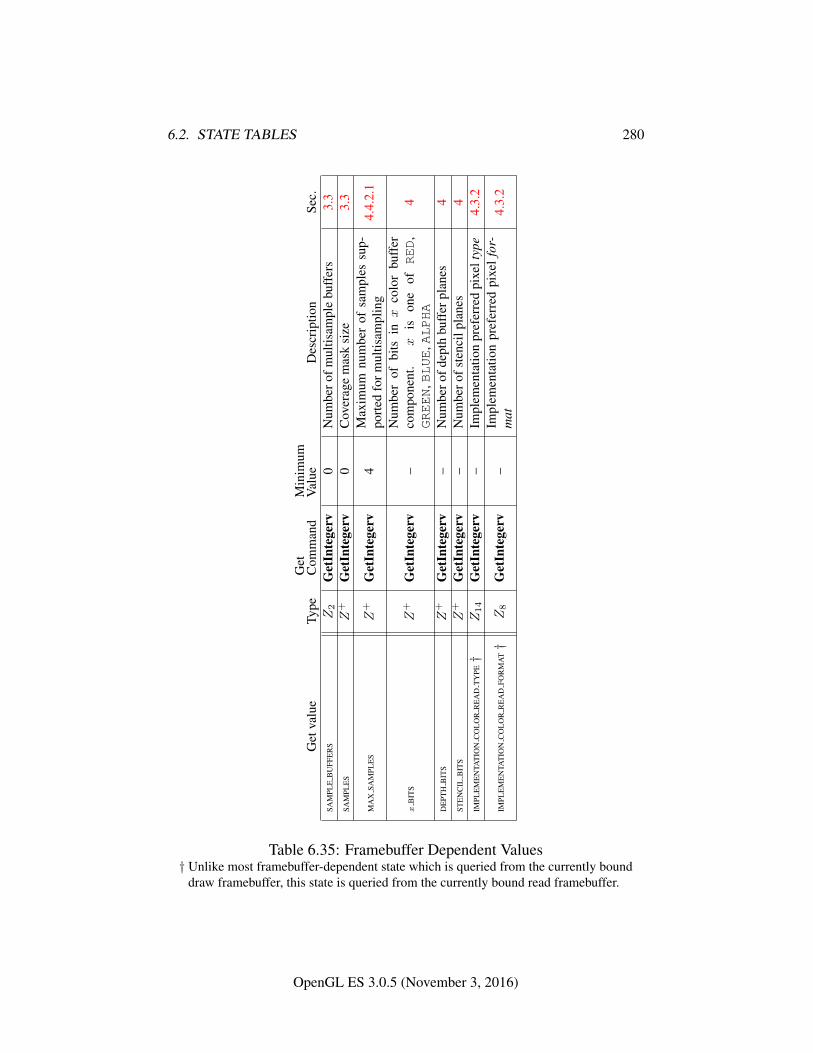
6.2. STATE TABLES 280
Get
valu
eTy
peG
etC
omm
and
Min
imum
Val
ueD
escr
iptio
nSe
c.SA
MPL
EB
UFF
ER
SZ2
Get
Inte
gerv
0N
umbe
rofm
ultis
ampl
ebu
ffer
s3.
3SA
MPL
ES
Z+
Get
Inte
gerv
0C
over
age
mas
ksi
ze3.
3
MA
XSA
MPL
ES
Z+
Get
Inte
gerv
4M
axim
umnu
mbe
rof
sam
ples
sup-
port
edfo
rmul
tisam
plin
g4.
4.2.
1
xB
ITS
Z+
Get
Inte
gerv
–N
umbe
rof
bits
inx
colo
rbu
ffer
com
pone
nt.
xis
one
ofRED
,GREEN
,BLUE
,ALPHA
4
DE
PTH
BIT
SZ
+G
etIn
tege
rv–
Num
bero
fdep
thbu
ffer
plan
es4
STE
NC
ILB
ITS
Z+
Get
Inte
gerv
–N
umbe
rofs
tenc
ilpl
anes
4IM
PLE
ME
NTA
TIO
NC
OL
OR
RE
AD
TY
PE†
Z14
Get
Inte
gerv
–Im
plem
enta
tion
pref
erre
dpi
xelt
ype
4.3.
2
IMPL
EM
EN
TAT
ION
CO
LO
RR
EA
DFO
RM
AT†
Z8
Get
Inte
gerv
–Im
plem
enta
tion
pref
erre
dpi
xel
for-
mat
4.3.
2
Table 6.35: Framebuffer Dependent Values† Unlike most framebuffer-dependent state which is queried from the currently bound
draw framebuffer, this state is queried from the currently bound read framebuffer.
OpenGL ES 3.0.5 (November 3, 2016)
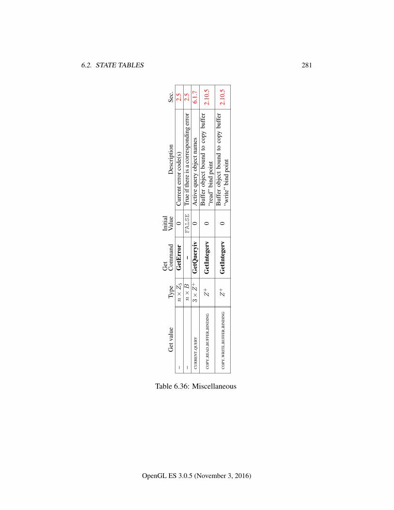
6.2. STATE TABLES 281
Get
valu
eTy
peG
etC
omm
and
Initi
alV
alue
Des
crip
tion
Sec.
–n×Z5
Get
Err
or0
Cur
rent
erro
rcod
e(s)
2.5
–n×B
–FALSE
True
ifth
ere
isa
corr
espo
ndin
ger
ror
2.5
CU
RR
EN
TQ
UE
RY3×Z
+G
etQ
uery
iv0
Act
ive
quer
yob
ject
nam
es6.
1.7
CO
PYR
EA
DB
UFF
ER
BIN
DIN
GZ
+G
etIn
tege
rv0
Buf
fer
obje
ctbo
und
toco
pybu
ffer
“rea
d”bi
ndpo
int
2.10
.5
CO
PYW
RIT
EB
UFF
ER
BIN
DIN
GZ
+G
etIn
tege
rv0
Buf
fer
obje
ctbo
und
toco
pybu
ffer
“wri
te”
bind
poin
t2.
10.5
Table 6.36: Miscellaneous
OpenGL ES 3.0.5 (November 3, 2016)
Appendix A
Invariance
The OpenGL ES specification is not pixel exact. It therefore does not guarantee anexact match between images produced by different GL implementations. However,the specification does specify exact matches, in some cases, for images producedby the same implementation. The purpose of this appendix is to identify and pro-vide justification for those cases that require exact matches.
A.1 Repeatability
The obvious and most fundamental case is repeated issuance of a series of GL com-mands. For any given GL and framebuffer state vector, and for any GL command,the resulting GL and framebuffer state must be identical whenever the command isexecuted on that initial GL and framebuffer state.
One purpose of repeatability is avoidance of visual artifacts when a double-buffered scene is redrawn. If rendering is not repeatable, swapping between twobuffers rendered with the same command sequence may result in visible changesin the image. Such false motion is distracting to the viewer. Another reason forrepeatability is testability.
Repeatability, while important, is a weak requirement. Given only repeata-bility as a requirement, two scenes rendered with one (small) polygon changedin position might differ at every pixel. Such a difference, while within the lawof repeatability, is certainly not within its spirit. Additional invariance rules aredesirable to ensure useful operation.
282
A.2. MULTI-PASS ALGORITHMS 283
A.2 Multi-pass Algorithms
Invariance is necessary for a whole set of useful multi-pass algorithms. Such al-gorithms render multiple times, each time with a different GL mode vector, toeventually produce a result in the framebuffer. Examples of these algorithms in-clude:
• “Erasing” a primitive from the framebuffer by redrawing it in a differentcolor.
• Using stencil operations to compute capping planes for stencil shadow vol-umes.
On the other hand, invariance rules can greatly increase the complexity of high-performance implementations of the GL. Even the weak repeatability requirementsignificantly constrains a parallel implementation of the GL. Because GL imple-mentations are required to implement ALL GL capabilities, not just a convenientsubset, those that utilize hardware acceleration are expected to alternate betweenhardware and software modules based on the current GL mode vector. A stronginvariance requirement forces the behavior of the hardware and software modulesto be identical, something that may be very difficult to achieve (for example, if thehardware does floating-point operations with different precision than the software).
What is desired is a compromise that results in many compliant, high-performance implementations, and in many software vendors choosing to port toOpenGL ES.
A.3 Invariance Rules
For a given instantiation of an OpenGL ES rendering context:
Rule 1 For any given GL and framebuffer state vector, and for any given GL com-mand, the resulting GL and framebuffer state must be identical each time the com-mand is executed on that initial GL and framebuffer state.
Rule 2 Changes to the following state values have no side effects (the use of anyother state value is not affected by the change):
Required:
• Framebuffer contents (all bitplanes)
• The color buffers enabled for writing
OpenGL ES 3.0.5 (November 3, 2016)
A.4. WHAT ALL THIS MEANS 284
• Scissor parameters (other than enable)
• Writemasks (color, depth, stencil)
• Clear values (color, depth, stencil)
Strongly suggested:
• Stencil parameters (other than enable)
• Depth test parameters (other than enable)
• Blend parameters (other than enable)
• Pixel storage state
• Polygon offset parameters (other than enables, and except as they affectthe depth values of fragments)
Corollary 1 Fragment generation is invariant with respect to the state valuesmarked with • in Rule 2.
Rule 3 The arithmetic of each per-fragment operation is invariant except with re-spect to parameters that directly control it.
Corollary 2 Images rendered into different color buffers sharing the same frame-buffer, either simultaneously or separately using the same command sequence, arepixel identical.
Rule 4 The same vertex or fragment shader will produce the same result whenrun multiple times with the same input. The wording ‘the same shader’ means aprogram object that is populated with the same source strings, which are compiledand then linked, possibly multiple times, and which program object is then executedusing the same GL state vector.
Rule 5 All fragment shaders that either conditionally or unconditionally assigngl_FragCoord.z to gl_FragDepth are depth-invariant with respect to eachother, for those fragments where the assignment to gl_FragDepth actually isdone.
A.4 What All This Means
Hardware accelerated GL implementations are expected to default to software op-eration when some GL state vectors are encountered. Even the weak repeatabilityrequirement means, for example, that OpenGL ES implementations cannot apply
OpenGL ES 3.0.5 (November 3, 2016)
A.4. WHAT ALL THIS MEANS 285
hysteresis to this swap, but must instead guarantee that a given mode vector im-plies that a subsequent command always is executed in either the hardware or thesoftware machine.
The stronger invariance rules constrain when the switch from hardware to soft-ware rendering can occur, given that the software and hardware renderers are notpixel identical. For example, the switch can be made when blending is enabled ordisabled, but it should not be made when a change is made to the blending param-eters.
Because floating point values may be represented using different formats indifferent renderers (hardware and software), many OpenGL ES state values maychange subtly when renderers are swapped. This is the type of state value changethat Rule 1 seeks to avoid.
OpenGL ES 3.0.5 (November 3, 2016)
Appendix B
Corollaries
The following observations are derived from the body and the other appendixes ofthe specification. Absence of an observation from this list in no way impugns itsveracity.
1. The error semantics of upward compatible OpenGL ES revisions maychange. Otherwise, only additions can be made to upward compatible re-visions.
2. GL query commands are not required to satisfy the semantics of the Flushor the Finish commands. All that is required is that the queried state be con-sistent with complete execution of all previously executed GL commands.
3. Application specified line width must be returned as specified when queried.Implementation-dependent clamping affects the values only while they arein use.
4. The mask specified as the third argument to StencilFunc affects the operandsof the stencil comparison function, but has no direct effect on the update ofthe stencil buffer. The mask specified by StencilMask has no effect on thestencil comparison function; it limits the effect of the update of the stencilbuffer.
5. There is no atomicity requirement for OpenGL ES rendering commands,even at the fragment level.
6. Because rasterization of polygons is point sampled, polygons that have noarea generate no fragments when they are rasterized, and the fragments gen-erated by the rasterization of “narrow” polygons may not form a continuousarray.
286
287
7. OpenGL ES does not force left- or right-handedness on any of its coordinatessystems.
8. (No pixel dropouts or duplicates.) Let two polygons share an identical edge.That is, there exist vertices A and B of an edge of one polygon, and verticesC and D of an edge of the other polygon; the positions of vertex A and Care identical; and the positions of vertex B and D are identical. Vertex po-sitions are identical if the gl_Position values output by the vertex shaderare identical. Then, when the fragments produced by rasterization of bothpolygons are taken together, each fragment intersecting the interior of theshared edge is produced exactly once.
9. Dithering algorithms may be different for different components. In particu-lar, alpha may be dithered differently from red, green, or blue, and an imple-mentation may choose to not dither alpha at all.
OpenGL ES 3.0.5 (November 3, 2016)
Appendix C
Compressed Texture ImageFormats
C.1 ETC Compressed Texture Image Formats
The ETC formats form a family of related compressed texture image formats. Theyare designed to do different tasks, but also to be similar enough that hardware canbe reused between them. Each one is described in detail below, but we will firstgive an overview of each format and describe how it is similar to others and themain differences.
COMPRESSED_RGB8_ETC2 is a format for compressing RGB8 data. It is a su-perset of the older OES_compressed_ETC1_RGB8_texture format. This meansthat an older ETC1 texture can be decoded using by a COMPRESSED_RGB8_ETC2-compliant decoder, using the enum-value for COMPRESSED_RGB8_ETC2. Themain difference is that the newer version contains three new modes; the ‘T-mode’and the ‘H-mode’ which are good for sharp chrominance blocks and the ‘Planar’mode which is good for smooth blocks.
COMPRESSED_SRGB8_ETC2 is the same as COMPRESSED_RGB8_ETC2 withthe difference that the values should be interpeted as sRGB-values instead of RGB-values.
COMPRESSED_RGBA8_ETC2_EAC encodes RGBA8 data. The RGB part is en-coded exactly the same way as COMPRESSED_RGB8_ETC2. The alpha part is en-coded separately.
COMPRESSED_SRGB8_ALPHA8_ETC2_EAC is the same as COMPRESSED_-
RGBA8_ETC2_EAC but here the RGB-values (but not the alpha value) should beinterpreted as sRGB-values.
288
C.1. ETC COMPRESSED TEXTURE IMAGE FORMATS 289
COMPRESSED_R11_EAC is a one-channel unsigned format. It is similar to thealpha part of COMPRESSED_SRGB8_ALPHA8_ETC2_EAC but not exactly the same;it delivers higher precision. It is possible to make hardware that can decode bothformats with minimal overhead.
COMPRESSED_RG11_EAC is a two-channel unsigned format. Each channel isdecoded exactly as COMPRESSED_R11_EAC.
COMPRESSED_SIGNED_R11_EAC is a one-channel signed format. This is goodin situations when it is important to be able to preserve zero exactly, and stilluse both positive and negative values. It is designed to be similar enough toCOMPRESSED_R11_EAC so that hardware can decode both with minimal overhead,but it is not exactly the same. For example; the signed version does not add 0.5 tothe base codeword, and the extension from 11 bits differ. For all details, see thecorresponding sections.
COMPRESSED_SIGNED_RG11_EAC is a two-channel signed format. Eachchannel is decoded exactly as COMPRESSED_SIGNED_R11_EAC.
COMPRESSED_RGB8_PUNCHTHROUGH_ALPHA1_ETC2 is very similar toCOMPRESSED_RGB8_ETC2, but has the ability to represent “punchthrough”-alpha(completely opaque or transparent). Each block can select to be completely opaqueusing one bit. To fit this bit, there is no individual mode in COMPRESSED_RGB8_-
PUNCHTHROUGH_ALPHA1_ETC2. In other respects, the opaque blocks are decodedas in COMPRESSED_RGB8_ETC2. For the transparent blocks, one index is reservedto represent transparency, and the decoding of the RGB channels are also affected.For details, see the corresponding sections.
COMPRESSED_SRGB8_PUNCHTHROUGH_ALPHA1_ETC2 isthe same as COMPRESSED_RGB8_PUNCHTHROUGH_ALPHA1_ETC2 but should beinterpreted as sRGB.
A texture compressed using any of the ETC texture image formats is describedas a number of 4× 4 pixel blocks.
Pixel a1 (see Table C.1) of the first block in memory will represent the texturecoordinate (u = 0, v = 0). Pixel a2 in the second block in memory will be adjacentto pixel m1 in the first block, etc. until the width of the texture. Then pixel a3 inthe following block (third block in memory for a 8× 8 texture) will be adjacent topixel d1 in the first block, etc. until the height of the texture. Calling Compressed-TexImage2D to get an 8× 8 texture using the first, second, third and fourth blockshown in Table C.1 would have the same effect as calling TexImage2D where thebytes describing the pixels would come in the following memory order: a1 e1 i1m1 a2 e2 i2 m2 b1 f1 j1 n1 b2 f2 j2 n2 c1 g1 k1 o1 c2 g2 k2 o2 d1 h1 l1 p1 d2 h2 l2p2 a3 e3 i3 m3 a4 e4 i4 m4 b3 f3 j3 n3 b4 f4 j4 n4 c3 g3 k3 o3 c4 g4 k4 o4 d3 h3 l3p3 d4 h4 l4 p4.
If the width or height of the texture (or a particular mip-level) is not a multiple
OpenGL ES 3.0.5 (November 3, 2016)
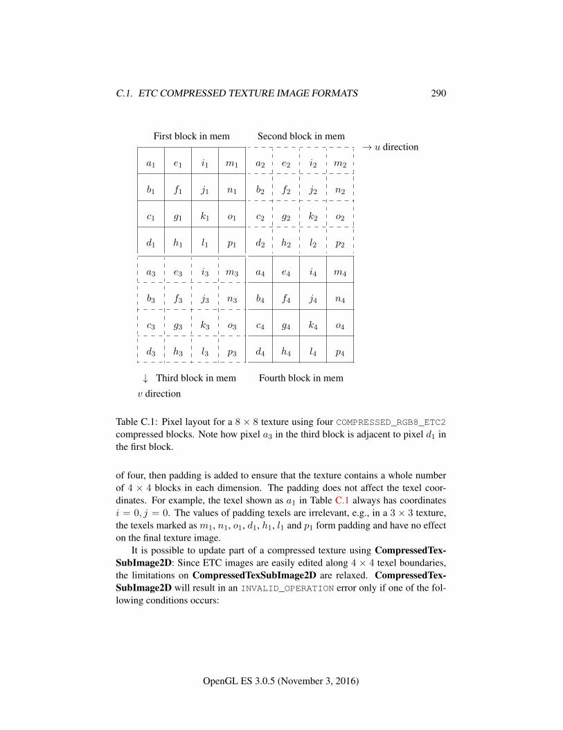
C.1. ETC COMPRESSED TEXTURE IMAGE FORMATS 290
First block in mem
a1 e1 i1 m1
b1 f1 j1 n1
c1 g1 k1 o1
d1 h1 l1 p1
Second block in mem
a2 e2 i2 m2
b2 f2 j2 n2
c2 g2 k2 o2
d2 h2 l2 p2
→ u direction
a3 e3 i3 m3
b3 f3 j3 n3
c3 g3 k3 o3
d3 h3 l3 p3
↓ Third block in mem
a4 e4 i4 m4
b4 f4 j4 n4
c4 g4 k4 o4
d4 h4 l4 p4
Fourth block in mem
v direction
Table C.1: Pixel layout for a 8 × 8 texture using four COMPRESSED_RGB8_ETC2compressed blocks. Note how pixel a3 in the third block is adjacent to pixel d1 inthe first block.
of four, then padding is added to ensure that the texture contains a whole numberof 4 × 4 blocks in each dimension. The padding does not affect the texel coor-dinates. For example, the texel shown as a1 in Table C.1 always has coordinatesi = 0, j = 0. The values of padding texels are irrelevant, e.g., in a 3 × 3 texture,the texels marked as m1, n1, o1, d1, h1, l1 and p1 form padding and have no effecton the final texture image.
It is possible to update part of a compressed texture using CompressedTex-SubImage2D: Since ETC images are easily edited along 4 × 4 texel boundaries,the limitations on CompressedTexSubImage2D are relaxed. CompressedTex-SubImage2D will result in an INVALID_OPERATION error only if one of the fol-lowing conditions occurs:
OpenGL ES 3.0.5 (November 3, 2016)
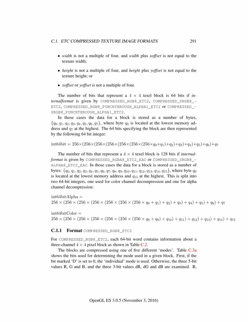
C.1. ETC COMPRESSED TEXTURE IMAGE FORMATS 291
• width is not a multiple of four, and width plus xoffset is not equal to thetexture width;
• height is not a multiple of four, and height plus yoffset is not equal to thetexture height; or
• xoffset or yoffset is not a multiple of four.
The number of bits that represent a 4 × 4 texel block is 64 bits if in-ternalformat is given by COMPRESSED_RGB8_ETC2, COMPRESSED_SRGB8_-
ETC2, COMPRESSED_RGB8_PUNCHTHROUGH_ALPHA1_ETC2 or COMPRESSED_-SRGB8_PUNCHTHROUGH_ALPHA1_ETC2.
In those cases the data for a block is stored as a number of bytes,{q0, q1, q2, q3, q4, q5, q6, q7}, where byte q0 is located at the lowest memory ad-dress and q7 at the highest. The 64 bits specifying the block are then representedby the following 64 bit integer:
int64bit = 256×(256×(256×(256×(256×(256×(256×q0+q1)+q2)+q3)+q4)+q5)+q6)+q7
The number of bits that represent a 4 × 4 texel block is 128 bits if internal-format is given by COMPRESSED_RGBA8_ETC2_EAC or COMPRESSED_SRGB8_-ALPHA8_ETC2_EAC. In those cases the data for a block is stored as a number ofbytes: {q0, q1, q2, q3, q4, q5, q6, q7, q8, q9, q10, q11, q12, q13, q14, q15}, where byte q0is located at the lowest memory address and q15 at the highest. This is split intotwo 64-bit integers, one used for color channel decompression and one for alphachannel decompression:
int64bitAlpha =256× (256× (256× (256× (256× (256× (256× q0 + q1) + q2) + q3) + q4) + q5) + q6) + q7
int64bitColor =256× (256× (256× (256× (256× (256× (256× q8 + q9) + q10) + q11) + q12) + q13) + q14) + q15
C.1.1 Format COMPRESSED_RGB8_ETC2
For COMPRESSED_RGB8_ETC2, each 64-bit word contains information about athree-channel 4× 4 pixel block as shown in Table C.2.
The blocks are compressed using one of five different ‘modes’. Table C.3ashows the bits used for determining the mode used in a given block. First, if thebit marked ‘D’ is set to 0, the ‘individual’ mode is used. Otherwise, the three 5-bitvalues R, G and B, and the three 3-bit values dR, dG and dB are examined. R,
OpenGL ES 3.0.5 (November 3, 2016)
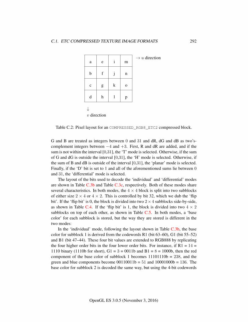
C.1. ETC COMPRESSED TEXTURE IMAGE FORMATS 292
a e i m
b f j n
c g k o
d h l p
↓v direction
→ u direction
Table C.2: Pixel layout for an COMPRESSED_RGB8_ETC2 compressed block.
G and B are treated as integers between 0 and 31 and dR, dG and dB as two’s-complement integers between −4 and +3. First, R and dR are added, and if thesum is not within the interval [0,31], the ‘T’ mode is selected. Otherwise, if the sumof G and dG is outside the interval [0,31], the ‘H’ mode is selected. Otherwise, ifthe sum of B and dB is outside of the interval [0,31], the ‘planar’ mode is selected.Finally, if the ‘D’ bit is set to 1 and all of the aforementioned sums lie between 0and 31, the ‘differential’ mode is selected.
The layout of the bits used to decode the ‘individual’ and ‘differential’ modesare shown in Table C.3b and Table C.3c, respectively. Both of these modes shareseveral characteristics. In both modes, the 4 × 4 block is split into two subblocksof either size 2 × 4 or 4 × 2. This is controlled by bit 32, which we dub the ‘flipbit’. If the ‘flip bit’ is 0, the block is divided into two 2×4 subblocks side-by-side,as shown in Table C.4. If the ‘flip bit’ is 1, the block is divided into two 4 × 2subblocks on top of each other, as shown in Table C.5. In both modes, a ‘basecolor’ for each subblock is stored, but the way they are stored is different in thetwo modes:
In the ‘individual’ mode, following the layout shown in Table C.3b, the basecolor for subblock 1 is derived from the codewords R1 (bit 63–60), G1 (bit 55–52)and B1 (bit 47–44). These four bit values are extended to RGB888 by replicatingthe four higher order bits in the four lower order bits. For instance, if R1 = 14 =1110 binary (1110b for short), G1 = 3 = 0011b and B1 = 8 = 1000b, then the redcomponent of the base color of subblock 1 becomes 11101110b = 238, and thegreen and blue components become 00110011b = 51 and 10001000b = 136. Thebase color for subblock 2 is decoded the same way, but using the 4-bit codewords
OpenGL ES 3.0.5 (November 3, 2016)
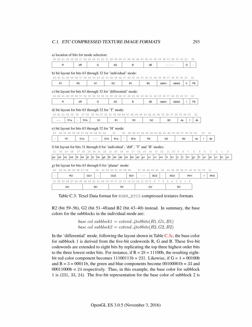
C.1. ETC COMPRESSED TEXTURE IMAGE FORMATS 293
a) location of bits for mode selection:63 62 61 60 59 58 57 56 55 54 53 52 51 50 49 48 47 46 45 44 43 42 41 40 39 38 37 36 35 34 33 32
R dR G dG B dB - - - - - - D -
b) bit layout for bits 63 through 32 for ’individual’ mode:63 62 61 60 59 58 57 56 55 54 53 52 51 50 49 48 47 46 45 44 43 42 41 40 39 38 37 36 35 34 33 32
R1 R2 G1 G2 B1 B2 table1 table2 0 FB
c) bit layout for bits 63 through 32 for ’differential’ mode:63 62 61 60 59 58 57 56 55 54 53 52 51 50 49 48 47 46 45 44 43 42 41 40 39 38 37 36 35 34 33 32
R dR G dG B dB table1 table2 1 FB
d) bit layout for bits 63 through 32 for ’T’ mode:63 62 61 60 59 58 57 56 55 54 53 52 51 50 49 48 47 46 45 44 43 42 41 40 39 38 37 36 35 34 33 32
- - - R1a - R1b G1 B1 R2 G2 B2 da 1 db
e) bit layout for bits 63 through 32 for ’H’ mode:63 62 61 60 59 58 57 56 55 54 53 52 51 50 49 48 47 46 45 44 43 42 41 40 39 38 37 36 35 34 33 32
- R1 G1a - - - G1b B1a - B1b R2 G2 B2 da 1 db
f) bit layout for bits 31 through 0 for ’individual’, ’diff’, ’T’ and ’H’ modes:31 30 29 28 27 26 25 24 23 22 21 20 19 18 17 16 15 14 13 12 11 10 9 8 7 6 5 4 3 2 1 0
p0 o0 n0 m0 l0 k0 j0 i0 h0 g0 f0 e0 d0 c0 b0 a0 p1 o1 n1 m1 l1 k1 j1 i1 h1 g1 f1 e1 d1 c1 b1 a1
g) bit layout for bits 63 through 0 for ’planar’ mode:63 62 61 60 59 58 57 56 55 54 53 52 51 50 49 48 47 46 45 44 43 42 41 40 39 38 37 36 35 34 33 32
- RO GO1 - GO2 BO1 - - - BO2 - BO3 RH1 1 RH2
31 30 29 28 27 26 25 24 23 22 21 20 19 18 17 16 15 14 13 12 11 10 9 8 7 6 5 4 3 2 1 0
GH BH RV GV BV
Table C.3: Texel Data format for RGB8_ETC2 compressed textures formats
R2 (bit 59–56), G2 (bit 51–48)and B2 (bit 43–40) instead. In summary, the basecolors for the subblocks in the individual mode are:
base col subblock1 = extend 4to8bits(R1, G1, B1)base col subblock2 = extend 4to8bits(R2, G2, B2)
In the ‘differential’ mode, following the layout shown in Table C.3c, the base colorfor subblock 1 is derived from the five-bit codewords R, G and B. These five-bitcodewords are extended to eight bits by replicating the top three highest order bitsto the three lowest order bits. For instance, if R = 28 = 11100b, the resulting eight-bit red color component becomes 11100111b = 231. Likewise, if G = 4 = 00100band B = 3 = 00011b, the green and blue components become 00100001b = 33 and00011000b = 24 respectively. Thus, in this example, the base color for subblock1 is (231, 33, 24). The five-bit representation for the base color of subblock 2 is
OpenGL ES 3.0.5 (November 3, 2016)
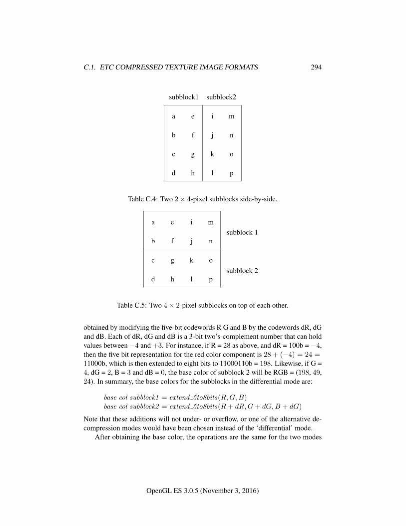
C.1. ETC COMPRESSED TEXTURE IMAGE FORMATS 294
subblock1 subblock2
a e i m
b f j n
c g k o
d h l p
Table C.4: Two 2× 4-pixel subblocks side-by-side.
a e i m
b f j n
c g k o
d h l p
subblock 1
subblock 2
Table C.5: Two 4× 2-pixel subblocks on top of each other.
obtained by modifying the five-bit codewords R G and B by the codewords dR, dGand dB. Each of dR, dG and dB is a 3-bit two’s-complement number that can holdvalues between −4 and +3. For instance, if R = 28 as above, and dR = 100b = −4,then the five bit representation for the red color component is 28 + (−4) = 24 =11000b, which is then extended to eight bits to 11000110b = 198. Likewise, if G =4, dG = 2, B = 3 and dB = 0, the base color of subblock 2 will be RGB = (198, 49,24). In summary, the base colors for the subblocks in the differential mode are:
base col subblock1 = extend 5to8bits(R,G,B)base col subblock2 = extend 5to8bits(R+ dR,G+ dG,B + dG)
Note that these additions will not under- or overflow, or one of the alternative de-compression modes would have been chosen instead of the ‘differential’ mode.
After obtaining the base color, the operations are the same for the two modes
OpenGL ES 3.0.5 (November 3, 2016)
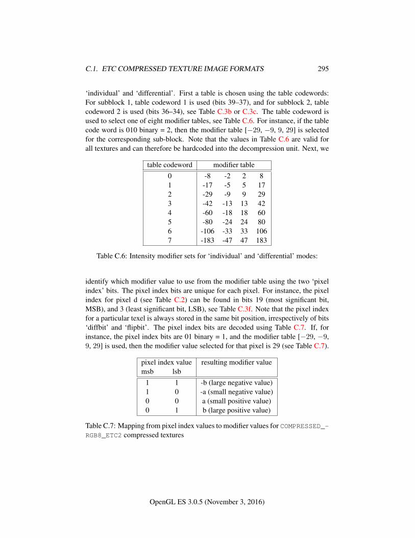
C.1. ETC COMPRESSED TEXTURE IMAGE FORMATS 295
‘individual’ and ‘differential’. First a table is chosen using the table codewords:For subblock 1, table codeword 1 is used (bits 39–37), and for subblock 2, tablecodeword 2 is used (bits 36–34), see Table C.3b or C.3c. The table codeword isused to select one of eight modifier tables, see Table C.6. For instance, if the tablecode word is 010 binary = 2, then the modifier table [−29, −9, 9, 29] is selectedfor the corresponding sub-block. Note that the values in Table C.6 are valid forall textures and can therefore be hardcoded into the decompression unit. Next, we
table codeword modifier table0 -8 -2 2 81 -17 -5 5 172 -29 -9 9 293 -42 -13 13 424 -60 -18 18 605 -80 -24 24 806 -106 -33 33 1067 -183 -47 47 183
Table C.6: Intensity modifier sets for ‘individual’ and ‘differential’ modes:
identify which modifier value to use from the modifier table using the two ‘pixelindex’ bits. The pixel index bits are unique for each pixel. For instance, the pixelindex for pixel d (see Table C.2) can be found in bits 19 (most significant bit,MSB), and 3 (least significant bit, LSB), see Table C.3f. Note that the pixel indexfor a particular texel is always stored in the same bit position, irrespectively of bits‘diffbit’ and ‘flipbit’. The pixel index bits are decoded using Table C.7. If, forinstance, the pixel index bits are 01 binary = 1, and the modifier table [−29, −9,9, 29] is used, then the modifier value selected for that pixel is 29 (see Table C.7).
pixel index value resulting modifier valuemsb lsb
1 1 -b (large negative value)1 0 -a (small negative value)0 0 a (small positive value)0 1 b (large positive value)
Table C.7: Mapping from pixel index values to modifier values for COMPRESSED_-RGB8_ETC2 compressed textures
OpenGL ES 3.0.5 (November 3, 2016)
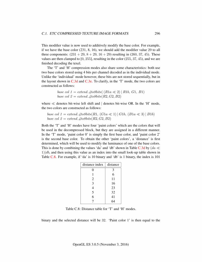
C.1. ETC COMPRESSED TEXTURE IMAGE FORMATS 296
This modifier value is now used to additively modify the base color. For example,if we have the base color (231, 8, 16), we should add the modifier value 29 to allthree components: (231 + 29, 8 + 29, 16 + 29) resulting in (260, 37, 45). Thesevalues are then clamped to [0, 255], resulting in the color (255, 37, 45), and we arefinished decoding the texel.
The ‘T’ and ‘H’ compression modes also share some characteristics: both usetwo base colors stored using 4 bits per channel decoded as in the individual mode.Unlike the ‘individual’ mode however, these bits are not stored sequentially, but inthe layout shown in C.3d and C.3e. To clarify, in the ‘T’ mode, the two colors areconstructed as follows:
base col 1 = extend 4to8bits( (R1a� 2) |R1b, G1, B1)base col 2 = extend 4to8bits(R2, G2, B2)
where � denotes bit-wise left shift and | denotes bit-wise OR. In the ‘H’ mode,the two colors are constructed as follows:
base col 1 = extend 4to8bits(R1, (G1a� 1) |G1b, (B1a� 3) |B1b)base col 2 = extend 4to8bits(R2, G2, B2)
Both the ‘T’ and ‘H’ modes have four ‘paint colors’ which are the colors that willbe used in the decompressed block, but they are assigned in a different manner.In the ‘T’ mode, ‘paint color 0’ is simply the first base color, and ‘paint color 2’is the second base color. To obtain the other ‘paint colors’, a ‘distance’ is firstdetermined, which will be used to modify the luminance of one of the base colors.This is done by combining the values ‘da’ and ‘db’ shown in Table C.3d by (da�1)|db, and then using this value as an index into the small look-up table shown inTable C.8. For example, if ‘da’ is 10 binary and ‘db’ is 1 binary, the index is 101
distance index distance0 31 62 113 164 235 326 417 64
Table C.8: Distance table for ‘T’ and ‘H’ modes.
binary and the selected distance will be 32. ‘Paint color 1’ is then equal to the
OpenGL ES 3.0.5 (November 3, 2016)
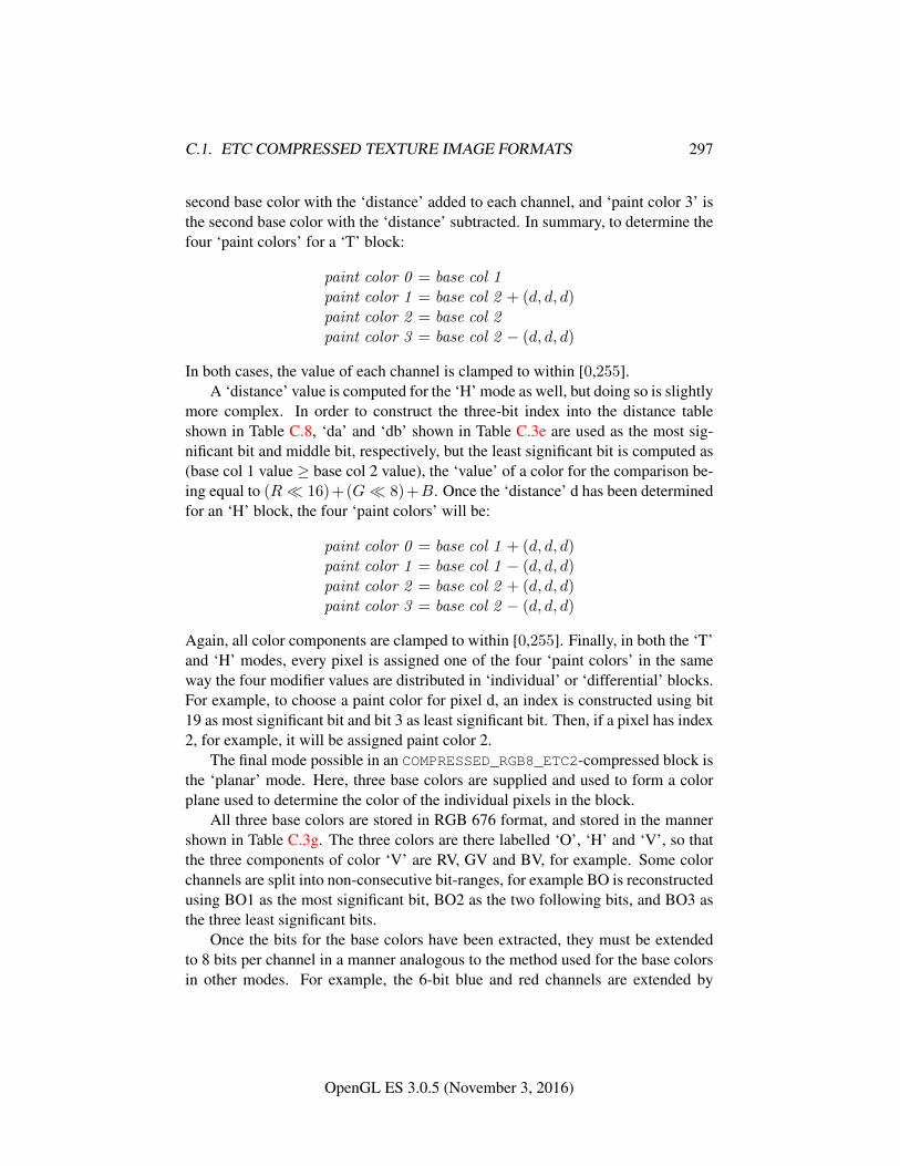
C.1. ETC COMPRESSED TEXTURE IMAGE FORMATS 297
second base color with the ‘distance’ added to each channel, and ‘paint color 3’ isthe second base color with the ‘distance’ subtracted. In summary, to determine thefour ‘paint colors’ for a ‘T’ block:
paint color 0 = base col 1paint color 1 = base col 2 + (d, d, d)paint color 2 = base col 2paint color 3 = base col 2 − (d, d, d)
In both cases, the value of each channel is clamped to within [0,255].A ‘distance’ value is computed for the ‘H’ mode as well, but doing so is slightly
more complex. In order to construct the three-bit index into the distance tableshown in Table C.8, ‘da’ and ‘db’ shown in Table C.3e are used as the most sig-nificant bit and middle bit, respectively, but the least significant bit is computed as(base col 1 value ≥ base col 2 value), the ‘value’ of a color for the comparison be-ing equal to (R� 16)+(G� 8)+B. Once the ‘distance’ d has been determinedfor an ‘H’ block, the four ‘paint colors’ will be:
paint color 0 = base col 1 + (d, d, d)paint color 1 = base col 1 − (d, d, d)paint color 2 = base col 2 + (d, d, d)paint color 3 = base col 2 − (d, d, d)
Again, all color components are clamped to within [0,255]. Finally, in both the ‘T’and ‘H’ modes, every pixel is assigned one of the four ‘paint colors’ in the sameway the four modifier values are distributed in ‘individual’ or ‘differential’ blocks.For example, to choose a paint color for pixel d, an index is constructed using bit19 as most significant bit and bit 3 as least significant bit. Then, if a pixel has index2, for example, it will be assigned paint color 2.
The final mode possible in an COMPRESSED_RGB8_ETC2-compressed block isthe ‘planar’ mode. Here, three base colors are supplied and used to form a colorplane used to determine the color of the individual pixels in the block.
All three base colors are stored in RGB 676 format, and stored in the mannershown in Table C.3g. The three colors are there labelled ‘O’, ‘H’ and ‘V’, so thatthe three components of color ‘V’ are RV, GV and BV, for example. Some colorchannels are split into non-consecutive bit-ranges, for example BO is reconstructedusing BO1 as the most significant bit, BO2 as the two following bits, and BO3 asthe three least significant bits.
Once the bits for the base colors have been extracted, they must be extendedto 8 bits per channel in a manner analogous to the method used for the base colorsin other modes. For example, the 6-bit blue and red channels are extended by
OpenGL ES 3.0.5 (November 3, 2016)
C.1. ETC COMPRESSED TEXTURE IMAGE FORMATS 298
replicating the two most significant of the six bits to the two least significant of thefinal 8 bits.
With three base colors in RGB888 format, the color of each pixel can then bedetermined as:
R(x, y) = x× (RH −RO)/4.0 + y × (RV −RO)/4.0 +ROG(x, y) = x× (GH −GO)/4.0 + y × (GV −GO)/4.0 +GOB(x, y) = x× (BH −BO)/4.0 + y × (BV −BO)/4.0 +BO
where x and y are values from 0 to 3 corresponding to the pixels coordinates withinthe block, x being in the u direction and y in the v direction. For example, the pixelg in Table C.2 would have x = 1 and y = 2.
These values are then rounded to the nearest integer (to the larger integer ifthere is a tie) and then clamped to a value between 0 and 255. Note that this isequivalent to
R(x, y) = clamp255((x× (RH −RO) + y × (RV −RO) + 4×RO + 2)� 2)G(x, y) = clamp255((x× (GH −GO) + y × (GV −GO) + 4×GO + 2)� 2)B(x, y) = clamp255((x× (BH −BO) + y × (BV −BO) + 4×BO + 2)� 2)
where clamp255 clamps the value to a number in the range [0, 255] and where�performs bit-wise right shift.
This specification gives the output for each compression mode in 8-bit integercolors between 0 and 255, and these values all need to be divided by 255 for thefinal floating point representation.
C.1.2 Format COMPRESSED_SRGB8_ETC2
Decompression of floating point sRGB values in COMPRESSED_SRGB8_ETC2 fol-lows that of floating point RGB values of COMPRESSED_RGB8_ETC2. The result issRGB values between 0.0 and 1.0. The further conversion from an sRGB encodedcomponent, cs, to a linear component, cl, is done according to Equation 3.26. As-sume cs is the sRGB component in the range [0,1].
C.1.3 Format COMPRESSED_RGBA8_ETC2_EAC
If internalformat is COMPRESSED_RGBA8_ETC2_EAC, each 4 × 4 block ofRGBA8888 information is compressed to 128 bits. To decode a block, thetwo 64-bit integers int64bitAlpha and int64bitColor are calculated as describedin Section C.1. The RGB component is then decoded the same way as for
OpenGL ES 3.0.5 (November 3, 2016)
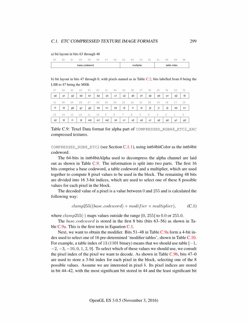
C.1. ETC COMPRESSED TEXTURE IMAGE FORMATS 299
a) bit layout in bits 63 through 4863 62 61 60 59 58 57 56 55 54 53 52 51 50 49 48
base codeword multiplier table index
b) bit layout in bits 47 through 0, with pixels named as in Table C.2, bits labelled from 0 being the
LSB to 47 being the MSB.47 46 45 44 43 42 41 40 39 38 37 36 35 34 33 32
a0 a1 a2 b0 b1 b2 c0 c1 c2 d0 d1 d2 e0 e1 e2 f0
31 30 29 28 27 26 25 24 23 22 21 20 19 18 17 16
f1 f2 g0 g1 g2 h0 h1 h2 i0 i1 i2 j0 j1 j2 k0 k1
15 14 13 12 11 10 9 8 7 6 5 4 3 2 1 0
k2 l0 l1 l2 m0 m1 m2 n0 n1 n2 o0 o1 o2 p0 p1 p2
Table C.9: Texel Data format for alpha part of COMPRESSED_RGBA8_ETC2_EACcompressed textures.
COMPRESSED_RGB8_ETC2 (see Section C.1.1), using int64bitColor as the int64bitcodeword.
The 64-bits in int64bitAlpha used to decompress the alpha channel are laidout as shown in Table C.9. The information is split into two parts. The first 16bits comprise a base codeword, a table codeword and a multiplier, which are usedtogether to compute 8 pixel values to be used in the block. The remaining 48 bitsare divided into 16 3-bit indices, which are used to select one of these 8 possiblevalues for each pixel in the block.
The decoded value of a pixel is a value between 0 and 255 and is calculated thefollowing way:
clamp255((base codeword) +modifier ×multiplier), (C.1)
where clamp255(·) maps values outside the range [0, 255] to 0.0 or 255.0.The base codeword is stored in the first 8 bits (bits 63–56) as shown in Ta-
ble C.9a. This is the first term in Equation C.1.Next, we want to obtain the modifier. Bits 51–48 in Table C.9a form a 4-bit in-
dex used to select one of 16 pre-determined ‘modifier tables’, shown in Table C.10.For example, a table index of 13 (1101 binary) means that we should use table [−1,−2,−3,−10, 0, 1, 2, 9]. To select which of these values we should use, we consultthe pixel index of the pixel we want to decode. As shown in Table C.9b, bits 47–0are used to store a 3-bit index for each pixel in the block, selecting one of the 8possible values. Assume we are interested in pixel b. Its pixel indices are storedin bit 44–42, with the most significant bit stored in 44 and the least significant bit
OpenGL ES 3.0.5 (November 3, 2016)
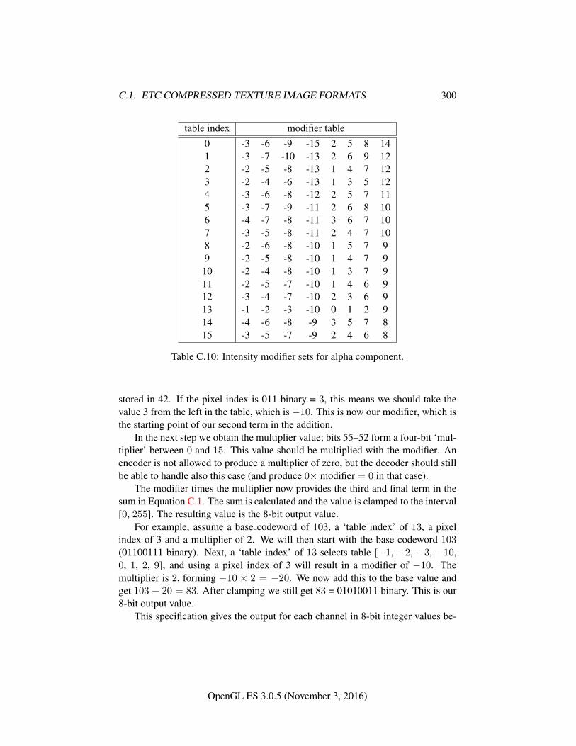
C.1. ETC COMPRESSED TEXTURE IMAGE FORMATS 300
table index modifier table0 -3 -6 -9 -15 2 5 8 141 -3 -7 -10 -13 2 6 9 122 -2 -5 -8 -13 1 4 7 123 -2 -4 -6 -13 1 3 5 124 -3 -6 -8 -12 2 5 7 115 -3 -7 -9 -11 2 6 8 106 -4 -7 -8 -11 3 6 7 107 -3 -5 -8 -11 2 4 7 108 -2 -6 -8 -10 1 5 7 99 -2 -5 -8 -10 1 4 7 910 -2 -4 -8 -10 1 3 7 911 -2 -5 -7 -10 1 4 6 912 -3 -4 -7 -10 2 3 6 913 -1 -2 -3 -10 0 1 2 914 -4 -6 -8 -9 3 5 7 815 -3 -5 -7 -9 2 4 6 8
Table C.10: Intensity modifier sets for alpha component.
stored in 42. If the pixel index is 011 binary = 3, this means we should take thevalue 3 from the left in the table, which is −10. This is now our modifier, which isthe starting point of our second term in the addition.
In the next step we obtain the multiplier value; bits 55–52 form a four-bit ‘mul-tiplier’ between 0 and 15. This value should be multiplied with the modifier. Anencoder is not allowed to produce a multiplier of zero, but the decoder should stillbe able to handle also this case (and produce 0× modifier = 0 in that case).
The modifier times the multiplier now provides the third and final term in thesum in Equation C.1. The sum is calculated and the value is clamped to the interval[0, 255]. The resulting value is the 8-bit output value.
For example, assume a base codeword of 103, a ‘table index’ of 13, a pixelindex of 3 and a multiplier of 2. We will then start with the base codeword 103(01100111 binary). Next, a ‘table index’ of 13 selects table [−1, −2, −3, −10,0, 1, 2, 9], and using a pixel index of 3 will result in a modifier of −10. Themultiplier is 2, forming −10 × 2 = −20. We now add this to the base value andget 103− 20 = 83. After clamping we still get 83 = 01010011 binary. This is our8-bit output value.
This specification gives the output for each channel in 8-bit integer values be-
OpenGL ES 3.0.5 (November 3, 2016)
C.1. ETC COMPRESSED TEXTURE IMAGE FORMATS 301
tween 0 and 255, and these values all need to be divided by 255 to obtain the finalfloating point representation.
Note that hardware can be effectively shared between the alpha decoding partof this format and that of COMPRESSED_R11_EAC texture. For details on how toreuse hardware, see Section C.1.5.
C.1.4 Format COMPRESSED_SRGB8_ALPHA8_ETC2_EAC
Decompression of floating point sRGB values in COMPRESSED_SRGB8_-
ALPHA8_ETC2_EAC follows that of floating point RGB values of RGBA8_ETC2_-EAC. The result is sRGB values between 0.0 and 1.0. The further conversion froman sRGB encoded component, cs, to a linear component, cl, is according to Equa-tion 3.26. Assume cs is the sRGB component in the range [0,1].
The alpha component of COMPRESSED_SRGB8_ALPHA8_ETC2_EAC is donein the same way as for COMPRESSED_RGBA8_ETC2_EAC.
C.1.5 Format COMPRESSED_R11_EAC
The number of bits to represent a 4 × 4 texel block is 64 bits if internalformatis given by COMPRESSED_R11_EAC. In that case the data for a block is stored asa number of bytes, {q0, q1, q2, q3, q4, q5, q6, q7}, where byte q0 is located at thelowest memory address and q7 at the highest. The red component of the 4 × 4block is then represented by the following 64 bit integer:
int64bit = 256×(256×(256×(256×(256×(256×(256×q0+q1)+q2)+q3)+q4)+q5)+q6)+q7
This 64-bit word contains information about a single-channel 4×4 pixel blockas shown in Table C.2. The 64-bit word is split into two parts. The first 16 bitscomprise a base codeword, a table codeword and a multiplier. The remaining 48bits are divided into 16 3-bit indices, which are used to select one of the 8 possiblevalues for each pixel in the block, as shown in Table C.9.
The decoded value is calculated as
clamp1((base codeword+0.5)× 1
255.875+modifier×multiplier× 1
255.875),
(C.2)where clamp1(·) maps values outside the range [0.0, 1.0] to 0.0 or 1.0.
We will now go into detail how the decoding is done. The result will be an11-bit fixed point number where 0 represents 0.0 and 2047 represents 1.0. This isthe exact representation for the decoded value. However, some implementationsmay use, e.g., 16-bits of accuracy for filtering. In such a case the 11-bit value willbe extended to 16 bits in a predefined way, which we will describe later.
OpenGL ES 3.0.5 (November 3, 2016)
C.1. ETC COMPRESSED TEXTURE IMAGE FORMATS 302
To get a value between 0 and 2047 we must multiply Equation C.2 by 2047.0:
clamp2((base codeword+0.5)× 2047.0
255.875+modifier×multiplier× 2047.0
255.875),
(C.3)where clamp2(·) clamps to the range [0.0, 2047.0]. Since 2047.0/255.875 is ex-actly 8.0, the above equation can be written as
clamp2(base codeword× 8 + 4 +modifier ×multiplier × 8) (C.4)
The base codeword is stored in the first 8 bits as shown in Table C.9a. Bits 63–56in each block represent an eight-bit integer (base codeword) which is multipliedby 8 by shifting three steps to the left. We can add 4 to this value without ad-dition logic by just inserting 100 binary in the last three bits after the shift. Forexample, if base codeword is 129 = 10000001 binary (or 10000001b for short),the shifted value is 10000001000b and the shifted value including the +4 term is10000001100b = 1036 = 129× 8 + 4. Hence we have summed together the firsttwo terms of the sum in Equation C.4.
Next, we want to obtain the modifier. Bits 51–48 form a 4-bit index usedto select one of 16 pre-determined ‘modifier tables’, shown in Table C.10. Forexample, a table index of 13 (1101 binary) means that we should use table [−1,−2, −3, −10, 0, 1, 2, 9]. To select which of these values we should use, weconsult the pixel index of the pixel we want to decode. Bits 47–0 are used to storea 3-bit index for each pixel in the block, selecting one of the 8 possible values.Assume we are interested in pixel b. Its pixel indices are stored in bit 44–42, withthe most significant bit stored in 44 and the least significant bit stored in 42. If thepixel index is 011 binary = 3, this means we should take the value 3 from the leftin the table, which is −10. This is now our modifier, which is the starting point ofour second term in the sum.
In the next step we obtain the multiplier value; bits 55–52 form a four-bit ‘mul-tiplier’ between 0 and 15. We will later treat what happens if the multiplier valueis zero, but if it is nonzero, it should be multiplied width the modifier. This productshould then be shifted three steps to the left to implement the ×8 multiplication.The result now provides the third and final term in the sum in C.4. The sum is cal-culated and the result is clamped to a value in the interval [0, 2047]. The resultingvalue is the 11-bit output value.
For example, assume a base codeword of 103, a ‘table index’ of 13, a pixelindex of 3 and a multiplier of 2 . We will then first multiply the base codeword103 (01100111b) by 8 by left-shifting it (0110111000b) and then add 4 resultingin 0110111100b = 828 = 103 × 8 + 4. Next, a ‘table index’ of 13 selects table[−1, −2, −3, −10, 0, 1, 2, 9], and using a pixel index of 3 will result in a modifier
OpenGL ES 3.0.5 (November 3, 2016)
C.1. ETC COMPRESSED TEXTURE IMAGE FORMATS 303
of −10. The multiplier is nonzero, which means that we should multiply it withthe modifier, forming −10 × 2 = −20 = 111111101100b. This value should inturn be multiplied by 8 by left-shifting it three steps: 111101100000b = −160.We now add this to the base value and get 828 − 160 = 668. After clamping westill get 668 = 01010011100b. This is our 11-bit output value, which representsthe value 668/2047 = 0.32633121 . . .
If the multiplier value is zero (i.e., the multiplier bits 55–52 are all zero), weshould set the multiplier to 1.0/8.0. Equation C.4 can then be simplified to
clamp2(base codeword× 8 + 4 +modifier) (C.5)
As an example, assume a base codeword of 103, a ‘table index’ of 13, a pixelindex of 3 and a multiplier value of 0. We treat the base codeword the same way,getting 828 = 103 × 8 + 4. The modifier is still -10. But the multiplier shouldnow be 1/8, which means that third term becomes −10 × (1/8) × 8 = −10. Thesum therefore becomes 828 − 10 = 818. After clamping we still get 818 =01100110010b, and this is our 11-bit output value, and it represents 818/2047 =0.39960918 . . .
Some OpenGL ES implementations may find it convenient to use 16-bit val-ues for further processing. In this case, the 11-bit value should be extendedusing bit replication. An 11-bit value x is extended to 16 bits through (x �5) + (x � 6). For example, the value 668 = 01010011100b should be extendedto 0101001110001010b = 21386.
In general, the implementation may extend the value to any number of bits thatis convenient for further processing, e.g., 32 bits. In these cases, bit replicationshould be used. On the other hand, an implementation is not allowed to truncatethe 11-bit value to less than 11 bits.
Note that the method does not have the same reconstruction levels as thealpha part in the COMPRESSED_RGBA8_ETC2_EAC-format. For instance, for abase value of 255 and a table value of 0, the alpha part of the COMPRESSED_-
RGBA8_ETC2_EAC-format will represent a value of (255 + 0)/255.0 = 1.0 ex-actly. In COMPRESSED_R11_EAC the same base value and table value will in-stead represent (255.5 + 0)/255.875 = 0.99853444 . . . That said, it is still possi-ble to decode the alpha part of the COMPRESSED_RGBA8_ETC2_EAC-format usingCOMPRESSED_R11_EAC-hardware. This is done by truncating the 11-bit numberto 8 bits. As an example, if base value = 255 and table value = 0, we get the 11-bitvalue (255 × 8 + 4 + 0) = 2044 = 1111111100b, which after truncation becomesthe 8-bit value 11111111b = 255 which is exactly the correct value according to theCOMPRESSED_RGBA8_ETC2_EAC. Clamping has to be done to [0, 255] after trun-cation for COMPRESSED_RGBA8_ETC2_EAC-decoding. Care must also be taken to
OpenGL ES 3.0.5 (November 3, 2016)
C.1. ETC COMPRESSED TEXTURE IMAGE FORMATS 304
handle the case when the multiplier value is zero. In the 11-bit version, this meansmultiplying by 1/8, but in the 8-bit version, it really means multiplication by 0.Thus, the decoder will have to know if it is a COMPRESSED_RGBA8_ETC2_EAC
texture or a COMPRESSED_R11_EAC texture to decode correctly, but the hardwarecan be 100% shared.
As stated above, a base value of 255 and a table value of 0 will represent avalue of (255.5 + 0)/255.875 = 0.99853444 . . ., and this does not reach 1.0 eventhough 255 is the highest possible base codeword. However, it is still possible toreach a pixel value of 1.0 since a modifier other than 0 can be used. Indeed, half ofthe modifiers will often produce a value of 1.0. As an example, assume we choosethe base value 255, a multiplier of 1 and the modifier table [−3 −5 −7 −9 2 4 6 8]. Starting with C.4,
clamp1((base codeword+0.5)× 1
255.875+table value×multiplier× 1
255.875)
we get
clamp1((255+0.5)× 1
255.875+[−3 −5 −7 −9 2 4 6 8
]× 1
255.875)
which equals
clamp1([
0.987 0.979 0.971 0.963 1.00 1.01 1.02 1.03])
or after clamping[0.987 0.979 0.971 0.963 1.00 1.00 1.00 1.00
]which shows that several values can be 1.0, even though the base value does notreach 1.0. The same reasoning goes for 0.0.
C.1.6 Format COMPRESSED_RG11_EAC
The number of bits to represent a 4 × 4 texel block is 128 bits if internalformatis given by COMPRESSED_RG11_EAC. In that case the data for a block is stored asa number of bytes, {q0, q1, q2, q3, q4, q5, q6, q7, p0, p1, p2, p3, p4, p5, p6, p7} wherebyte q0 is located at the lowest memory address and p7 at the highest. The 128 bitsspecifying the block are then represented by the following two 64 bit integers:
int64bit0 = 256×(256×(256×(256×(256×(256×(256×q0+q1)+q2)+q3)+q4)+q5)+q6)+q7int64bit1 = 256×(256×(256×(256×(256×(256×(256×p0+p1)+p2)+p3)+p4)+p5)+p6)+p7The 64-bit word int64bit0 contains information about the red component of a two-channel 4x4 pixel block as shown in Table C.2, and the word int64bit1 containsinformation about the green component. Both 64-bit integers are decoded in thesame way as COMPRESSED_R11_EAC described in Section C.1.5.
OpenGL ES 3.0.5 (November 3, 2016)
C.1. ETC COMPRESSED TEXTURE IMAGE FORMATS 305
C.1.7 Format COMPRESSED_SIGNED_R11_EAC
The number of bits to represent a 4 × 4 texel block is 64 bits if internalformatis given by COMPRESSED_SIGNED_R11_EAC. In that case the data for a block isstored as a number of bytes, {q0, q1, q2, q3, q4, q5, q6, q7}, where byte q0 is locatedat the lowest memory address and q7 at the highest. The red component of the 4×4block is then represented by the following 64 bit integer:
int64bit = 256×(256×(256×(256×(256×(256×(256×q0+q1)+q2)+q3)+q4)+q5)+q6)+q7
This 64-bit word contains information about a single-channel 4×4 pixel blockas shown in Table C.2. The 64-bit word is split into two parts. The first 16 bitscomprise a base codeword, a table codeword and a multiplier. The remaining 48bits are divided into 16 3-bit indices, which are used to select one of the 8 possiblevalues for each pixel in the block, as shown in Table C.9.
The decoded value is calculated as
clamp1(base codeword× 1
127.875+modifier×multiplier× 1
127.875) (C.6)
where clamp1(·) maps values outside the range [−1.0, 1.0] to −1.0 or 1.0. Wewill now go into detail how the decoding is done. The result will be an 11-bittwo’s-complement fixed point number where −1023 represents −1.0 and 1023represents 1.0. This is the exact representation for the decoded value. However,some implementations may use, e.g., 16-bits of accuracy for filtering. In such acase the 11-bit value will be extended to 16 bits in a predefined way, which we willdescribe later.
To get a value between −1023 and 1023 we must multiply Equation C.6 by1023.0:
clamp2(base codeword× 1023.0
127.875+modifier×multiplier× 1023.0
127.875), (C.7)
where clamp2(.) clamps to the range [−1023.0, 1023.0]. Since 1023.0/127.875 isexactly 8, the above formula can be written as
clamp2(base codeword× 8 +modifier ×multiplier × 8). (C.8)
The base codeword is stored in the first 8 bits as shown in Table C.9a. It is atwo’s-complement value in the range [−127, 127], and where the value−128 is notallowed; however, if it should occur anyway it must be treated as−127. The base -codeword is then multiplied by 8 by shifting it left three steps. For example thevalue 65 = 01000001 binary (or 01000001b for short) is shifted to 01000001000b= 520 = 65× 8.
OpenGL ES 3.0.5 (November 3, 2016)
C.1. ETC COMPRESSED TEXTURE IMAGE FORMATS 306
Next, we want to obtain the modifier. Bits 51–48 form a 4-bit index usedto select one of 16 pre-determined ‘modifier tables’, shown in Table C.10. Forexample, a table index of 13 (1101 binary) means that we should use table [−1,−2, −3, −10, 0, 1, 2, 9]. To select which of these values we should use, weconsult the pixel index of the pixel we want to decode. Bits 47–0 are used to storea 3-bit index for each pixel in the block, selecting one of the 8 possible values.Assume we are interested in pixel b. Its pixel indices are stored in bit 44–42, withthe most significant bit stored in 44 and the least significant bit stored in 42. If thepixel index is 011 binary = 3, this means we should take the value 3 from the leftin the table, which is −10. This is now our modifier, which is the starting point ofour second term in the sum.
In the next step we obtain the multiplier value; bits 55–52 form a four-bit ‘mul-tiplier’ between 0 and 15. We will later treat what happens if the multiplier valueis zero, but if it is nonzero, it should be multiplied with the modifier. This productshould then be shifted three steps to the left to implement the ×8 multiplication.The result now provides the third and final term in the sum in Equation C.8. Thesum is calculated and the result is clamped to a value in the interval [−1023, 1023].The resulting value is the 11-bit output value.
For example, assume a a base codeword of 60, a ‘table index’ of 13, a pixelindex of 3 and a multiplier of 2. We start by multiplying the base codeword(00111100b) by 8 using bit shift, resulting in (00111100000b) = 480 = 60 × 8.Next, a ‘table index’ of 13 selects table [−1, −2, −3, −10, 0, 1, 2, 9], and using apixel index of 3 will result in a modifier of −10. The multiplier is nonzero, whichmeans that we should multiply it with the modifier, forming −10 × 2 = −20 =111111101100b. This value should in turn be multiplied by 8 by left-shifting itthree steps: 111101100000b = −160. We now add this to the base value and get480 − 160 = 320. After clamping we still get 320 = 00101000000b. This is our11-bit output value, which represents the value 320/1023 = 0.31280547 . . .
If the multiplier value is zero (i.e., the multiplier bits 55–52 are all zero), weshould set the multiplier to 1.0/8.0. Equation C.8 can then be simplified to
clamp2(base codeword× 8 +modifier) (C.9)
As an example, assume a base codeword of 65, a ‘table index’ of 13, a pixel in-dex of 3 and a multiplier value of 0. We treat the base codeword the same way,getting 480 = 60 × 8. The modifier is still −10. But the multiplier should nowbe 1/8, which means that third term becomes −10 ∗ (1/8) × 8 = −10. The sumtherefore becomes 480− 10 = 470. Clamping does not affect the value since it isalready in the range [−1023, 1023], and the 11-bit output value is therefore 470 =00111010110b. This represents 470/1023 = 0.45943304 . . .
OpenGL ES 3.0.5 (November 3, 2016)
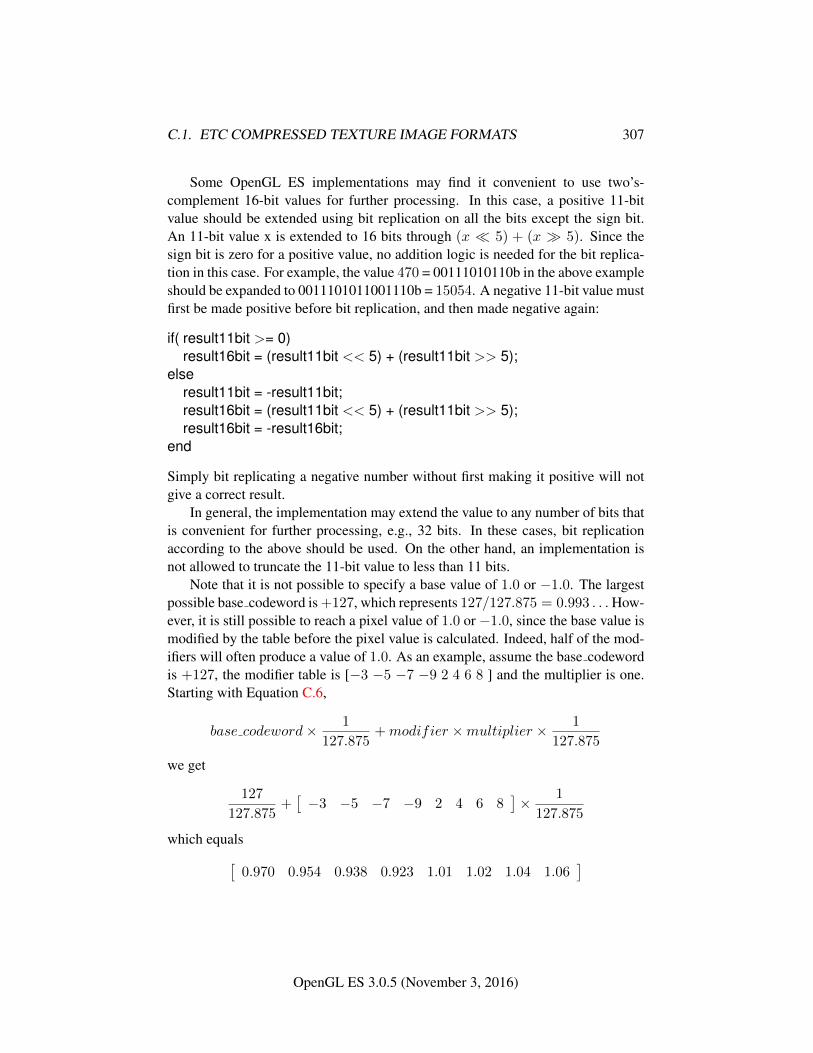
C.1. ETC COMPRESSED TEXTURE IMAGE FORMATS 307
Some OpenGL ES implementations may find it convenient to use two’s-complement 16-bit values for further processing. In this case, a positive 11-bitvalue should be extended using bit replication on all the bits except the sign bit.An 11-bit value x is extended to 16 bits through (x � 5) + (x � 5). Since thesign bit is zero for a positive value, no addition logic is needed for the bit replica-tion in this case. For example, the value 470 = 00111010110b in the above exampleshould be expanded to 0011101011001110b = 15054. A negative 11-bit value mustfirst be made positive before bit replication, and then made negative again:
if( result11bit >= 0)result16bit = (result11bit << 5) + (result11bit >> 5);
elseresult11bit = -result11bit;result16bit = (result11bit << 5) + (result11bit >> 5);result16bit = -result16bit;
end
Simply bit replicating a negative number without first making it positive will notgive a correct result.
In general, the implementation may extend the value to any number of bits thatis convenient for further processing, e.g., 32 bits. In these cases, bit replicationaccording to the above should be used. On the other hand, an implementation isnot allowed to truncate the 11-bit value to less than 11 bits.
Note that it is not possible to specify a base value of 1.0 or −1.0. The largestpossible base codeword is +127, which represents 127/127.875 = 0.993 . . .How-ever, it is still possible to reach a pixel value of 1.0 or −1.0, since the base value ismodified by the table before the pixel value is calculated. Indeed, half of the mod-ifiers will often produce a value of 1.0. As an example, assume the base codewordis +127, the modifier table is [−3 −5 −7 −9 2 4 6 8 ] and the multiplier is one.Starting with Equation C.6,
base codeword× 1
127.875+modifier ×multiplier × 1
127.875
we get
127
127.875+[−3 −5 −7 −9 2 4 6 8
]× 1
127.875
which equals[0.970 0.954 0.938 0.923 1.01 1.02 1.04 1.06
]
OpenGL ES 3.0.5 (November 3, 2016)
C.1. ETC COMPRESSED TEXTURE IMAGE FORMATS 308
or after clamping[0.970 0.954 0.938 0.923 1.00 1.00 1.00 1.00
]This shows that it is indeed possible to arrive at the value 1.0. The same reasoninggoes for −1.0.
Note also that Equations C.8/C.9 are very similar to Equations C.4/C.5 in theunsigned version EAC R11. Apart from the +4, the clamping and the extension tobitsizes other than 11, the same decoding hardware can be shared between the twocodecs.
C.1.8 Format COMPRESSED_SIGNED_RG11_EAC
The number of bits to represent a 4 × 4 texel block is 128 bits if internalformatis given byCOMPRESSED_SIGNED_RG11_EAC. In that case the data for a block is stored asa number of bytes, {q0, q1, q2, q3, q4, q5, q6, q7, p0, p1, p2, p3, p4, p5, p6, p7} wherebyte q0 is located at the lowest memory address and p7 at the highest. The 128 bitsspecifying the block are then represented by the following two 64 bit integers:
int64bit0 = 256×(256×(256×(256×(256×(256×(256×q0+q1)+q2)+q3)+q4)+q5)+q6)+q7
int64bit1 = 256×(256×(256×(256×(256×(256×(256×p0+p1)+p2)+p3)+p4)+p5)+p6)+p7The 64-bit word int64bit0 contains information about the red component of a two-channel 4 × 4 pixel block as shown in Table C.2, and the word int64bit1 containsinformation about the green component. Both 64-bit integers are decoded in thesame way as COMPRESSED_SIGNED_R11_EAC described in Section C.1.7.
C.1.9 Format COMPRESSED_RGB8_PUNCHTHROUGH_ALPHA1_ETC2
For COMPRESSED_RGB8_PUNCHTHROUGH_ALPHA1_ETC2, each 64-bit word con-tains information about a four-channel 4× 4 pixel block as shown in Table C.2.
The blocks are compressed using one of four different ‘modes’. Table C.11ashows the bits used for determining the mode used in a given block.
To determine the mode, the three 5-bit values R, G and B, and the three 3-bitvalues dR, dG and dB are examined. R, G and B are treated as integers between0 and 31 and dR, dG and dB as two’s-complement integers between −4 and +3.First, R and dR are added, and if the sum is not within the interval [0,31], the ‘T’mode is selected. Otherwise, if the sum of G and dG is outside the interval [0,31],the ‘H’ mode is selected. Otherwise, if the sum of B and dB is outside of the
OpenGL ES 3.0.5 (November 3, 2016)
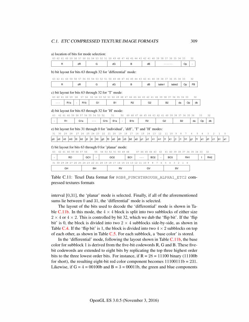
C.1. ETC COMPRESSED TEXTURE IMAGE FORMATS 309
a) location of bits for mode selection:63 62 61 60 59 58 57 56 55 54 53 52 51 50 49 48 47 46 45 44 43 42 41 40 39 38 37 36 35 34 33 32
R dR G dG B dB - - - - - - Op -
b) bit layout for bits 63 through 32 for ’differential’ mode:
63 62 61 60 59 58 57 56 55 54 53 52 51 50 49 48 47 46 45 44 43 42 41 40 39 38 37 36 35 34 33 32
R dR G dG B dB table1 table2 Op FB
c) bit layout for bits 63 through 32 for ’T’ mode:63 62 61 60 59 58 57 56 55 54 53 52 51 50 49 48 47 46 45 44 43 42 41 40 39 38 37 36 35 34 33 32
- - - R1a - R1b G1 B1 R2 G2 B2 da Op db
d) bit layout for bits 63 through 32 for ’H’ mode:63 62 61 60 59 58 57 56 55 54 53 52 51 50 49 48 47 46 45 44 43 42 41 40 39 38 37 36 35 34 33 32
- R1 G1a - - - G1b B1a - B1b R2 G2 B2 da Op db
e) bit layout for bits 31 through 0 for ’individual’, ’diff’, ’T’ and ’H’ modes:31 30 29 28 27 26 25 24 23 22 21 20 19 18 17 16 15 14 13 12 11 10 9 8 7 6 5 4 3 2 1 0
p0 o0 n0 m0 l0 k0 j0 i0 h0 g0 f0 e0 d0 c0 b0 a0 p1 o1 n1 m1 l1 k1 j1 i1 h1 g1 f1 e1 d1 c1 b1 a1
f) bit layout for bits 63 through 0 for ’planar’ mode:63 62 61 60 59 58 57 56 55 54 53 52 51 50 49 48 47 46 45 44 43 42 41 40 39 38 37 36 35 34 33 32
- RO GO1 - GO2 BO1 - - - BO2 - BO3 RH1 1 RH2
31 30 29 28 27 26 25 24 23 22 21 20 19 18 17 16 15 14 13 12 11 10 9 8 7 6 5 4 3 2 1 0
GH BH RV GV BV
Table C.11: Texel Data format for RGB8_PUNCHTHROUGH_ALPHA1_ETC2 com-pressed textures formats
interval [0,31], the ‘planar’ mode is selected. Finally, if all of the aforementionedsums lie between 0 and 31, the ‘differential’ mode is selected.
The layout of the bits used to decode the ‘differential’ mode is shown in Ta-ble C.11b. In this mode, the 4 × 4 block is split into two subblocks of either size2× 4 or 4× 2. This is controlled by bit 32, which we dub the ‘flip bit’. If the ‘flipbit’ is 0, the block is divided into two 2 × 4 subblocks side-by-side, as shown inTable C.4. If the ‘flip bit’ is 1, the block is divided into two 4× 2 subblocks on topof each other, as shown in Table C.5. For each subblock, a ‘base color’ is stored.
In the ‘differential’ mode, following the layout shown in Table C.11b, the basecolor for subblock 1 is derived from the five-bit codewords R, G and B. These five-bit codewords are extended to eight bits by replicating the top three highest orderbits to the three lowest order bits. For instance, if R = 28 = 11100 binary (11100bfor short), the resulting eight-bit red color component becomes 11100111b = 231.Likewise, if G = 4 = 00100b and B = 3 = 00011b, the green and blue components
OpenGL ES 3.0.5 (November 3, 2016)
C.1. ETC COMPRESSED TEXTURE IMAGE FORMATS 310
become 00100001b = 33 and 00011000b = 24 respectively. Thus, in this example,the base color for subblock 1 is (231, 33, 24). The five bit representation for thebase color of subblock 2 is obtained by modifying the 5-bit codewords R, G andB by the codewords dR, dG and dB. Each of dR, dG and dB is a 3-bit two’s-complement number that can hold values between −4 and +3. For instance, if R= 28 as above, and dR = 100b = −4, then the five bit representation for the redcolor component is 28 + (−4) = 24 = 11000b, which is then extended to eightbits to 11000110b = 198. Likewise, if G = 4, dG = 2, B = 3 and dB = 0, the basecolor of subblock 2 will be RGB = (198, 49, 24). In summary, the base colors forthe subblocks in the differential mode are:
base col subblock1 = extend 5to8bits(R,G,B)base col subblock2 = extend 5to8bits(R+ dR,G+ dG,B + dG)
Note that these additions will not under- or overflow, or one of the alternative de-compression modes would have been chosen instead of the ‘differential’ mode.
After obtaining the base color, a table is chosen using the table codewords: Forsubblock 1, table codeword 1 is used (bits 39–37), and for subblock 2, table code-word 2 is used (bits 36–34), see Table C.11b. The table codeword is used to selectone of eight modifier tables. If the ‘opaque’-bit (bit 33) is set, Table C.12a is used.If it is unset, Table C.12b is used. For instance, if the ‘opaque’-bit is 1 and the tablecode word is 010 binary = 2, then the modifier table [−29, −9, 9, 29] is selectedfor the corresponding sub-block. Note that the values in Tables C.12a and C.12bare valid for all textures and can therefore be hardcoded into the decompressionunit.
Next, we identify which modifier value to use from the modifier table using thetwo ‘pixel index’ bits. The pixel index bits are unique for each pixel. For instance,the pixel index for pixel d (see Table C.2) can be found in bits 19 (most significantbit, MSB), and 3 (least significant bit, LSB), see Table C.11e. Note that the pixelindex for a particular texel is always stored in the same bit position, irrespectivelyof the ‘flipbit’.
If the ‘opaque’-bit (bit 33) is set, the pixel index bits are decoded using Ta-ble C.13a. If the ‘opaque’-bit is unset, Table C.13b will be used instead. If, forinstance, the ‘opaque’-bit is 1, and the pixel index bits are 01 binary = 1, and themodifier table [−29, −9, 9, 29] is used, then the modifier value selected for thatpixel is 29 (see Table C.13a). This modifier value is now used to additively modifythe base color. For example, if we have the base color (231, 8, 16), we should addthe modifier value 29 to all three components: (231+29, 8+29, 16+29) resultingin (260, 37, 45). These values are then clamped to [0, 255], resulting in the color(255, 37, 45).
OpenGL ES 3.0.5 (November 3, 2016)
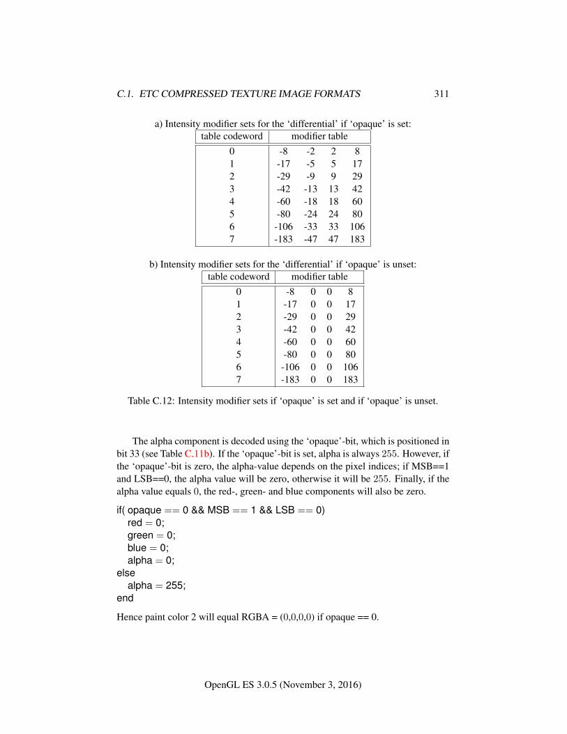
C.1. ETC COMPRESSED TEXTURE IMAGE FORMATS 311
a) Intensity modifier sets for the ‘differential’ if ‘opaque’ is set:table codeword modifier table
0 -8 -2 2 81 -17 -5 5 172 -29 -9 9 293 -42 -13 13 424 -60 -18 18 605 -80 -24 24 806 -106 -33 33 1067 -183 -47 47 183
b) Intensity modifier sets for the ‘differential’ if ‘opaque’ is unset:table codeword modifier table
0 -8 0 0 81 -17 0 0 172 -29 0 0 293 -42 0 0 424 -60 0 0 605 -80 0 0 806 -106 0 0 1067 -183 0 0 183
Table C.12: Intensity modifier sets if ‘opaque’ is set and if ‘opaque’ is unset.
The alpha component is decoded using the ‘opaque’-bit, which is positioned inbit 33 (see Table C.11b). If the ‘opaque’-bit is set, alpha is always 255. However, ifthe ‘opaque’-bit is zero, the alpha-value depends on the pixel indices; if MSB==1and LSB==0, the alpha value will be zero, otherwise it will be 255. Finally, if thealpha value equals 0, the red-, green- and blue components will also be zero.
if( opaque == 0 && MSB == 1 && LSB == 0)red = 0;green = 0;blue = 0;alpha = 0;
elsealpha = 255;
end
Hence paint color 2 will equal RGBA = (0,0,0,0) if opaque == 0.
OpenGL ES 3.0.5 (November 3, 2016)
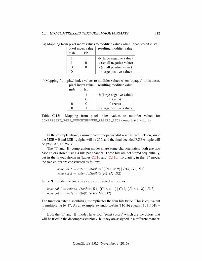
C.1. ETC COMPRESSED TEXTURE IMAGE FORMATS 312
a) Mapping from pixel index values to modifier values when ‘opaque’-bit is set.pixel index value resulting modifier valuemsb lsb
1 1 -b (large negative value)1 0 -a (small negative value)0 0 a (small positive value)0 1 b (large positive value)
b) Mapping from pixel index values to modifier values when ‘opaque’-bit is unset.pixel index value resulting modifier valuemsb lsb
1 1 -b (large negative value)1 0 0 (zero)0 0 0 (zero)0 1 b (large positive value)
Table C.13: Mapping from pixel index values to modifier values forCOMPRESSED_RGB8_PUNCHTHROUGH_ALPHA1_ETC2 compressed textures
In the example above, assume that the ‘opaque’-bit was instead 0. Then, sincethe MSB = 0 and LSB 1, alpha will be 255, and the final decoded RGBA-tuple willbe (255, 37, 45, 255).
The ‘T’ and ‘H’ compression modes share some characteristics: both use twobase colors stored using 4 bits per channel. These bits are not stored sequentially,but in the layout shown in Tables C.11c and C.11d. To clarify, in the ‘T’ mode,the two colors are constructed as follows:
base col 1 = extend 4to8bits( (R1a� 2) |R1b, G1, B1)base col 2 = extend 4to8bits(R2, G2, B2)
In the ‘H’ mode, the two colors are constructed as follows:
base col 1 = extend 4to8bits(R1, (G1a� 1) |G1b, (B1a� 3) |B1b)base col 2 = extend 4to8bits(R2, G2, B2)
The function extend 4to8bits() just replicates the four bits twice. This is equivalentto multiplying by 17. As an example, extend 4to8bits(1101b) equals 11011101b =221.
Both the ‘T’ and ‘H’ modes have four ‘paint colors’ which are the colors thatwill be used in the decompressed block, but they are assigned in a different manner.
OpenGL ES 3.0.5 (November 3, 2016)
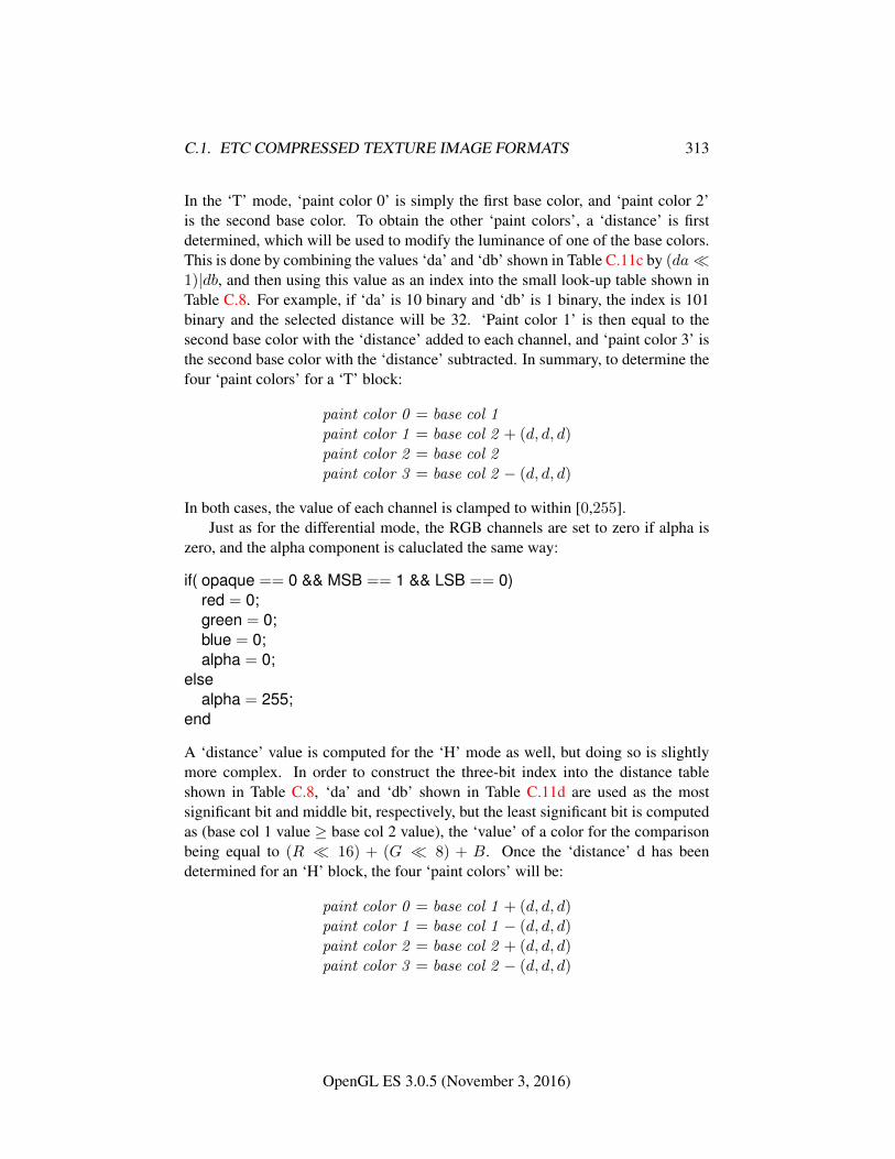
C.1. ETC COMPRESSED TEXTURE IMAGE FORMATS 313
In the ‘T’ mode, ‘paint color 0’ is simply the first base color, and ‘paint color 2’is the second base color. To obtain the other ‘paint colors’, a ‘distance’ is firstdetermined, which will be used to modify the luminance of one of the base colors.This is done by combining the values ‘da’ and ‘db’ shown in Table C.11c by (da�1)|db, and then using this value as an index into the small look-up table shown inTable C.8. For example, if ‘da’ is 10 binary and ‘db’ is 1 binary, the index is 101binary and the selected distance will be 32. ‘Paint color 1’ is then equal to thesecond base color with the ‘distance’ added to each channel, and ‘paint color 3’ isthe second base color with the ‘distance’ subtracted. In summary, to determine thefour ‘paint colors’ for a ‘T’ block:
paint color 0 = base col 1paint color 1 = base col 2 + (d, d, d)paint color 2 = base col 2paint color 3 = base col 2 − (d, d, d)
In both cases, the value of each channel is clamped to within [0,255].Just as for the differential mode, the RGB channels are set to zero if alpha is
zero, and the alpha component is caluclated the same way:
if( opaque == 0 && MSB == 1 && LSB == 0)red = 0;green = 0;blue = 0;alpha = 0;
elsealpha = 255;
end
A ‘distance’ value is computed for the ‘H’ mode as well, but doing so is slightlymore complex. In order to construct the three-bit index into the distance tableshown in Table C.8, ‘da’ and ‘db’ shown in Table C.11d are used as the mostsignificant bit and middle bit, respectively, but the least significant bit is computedas (base col 1 value ≥ base col 2 value), the ‘value’ of a color for the comparisonbeing equal to (R � 16) + (G � 8) + B. Once the ‘distance’ d has beendetermined for an ‘H’ block, the four ‘paint colors’ will be:
paint color 0 = base col 1 + (d, d, d)paint color 1 = base col 1 − (d, d, d)paint color 2 = base col 2 + (d, d, d)paint color 3 = base col 2 − (d, d, d)
OpenGL ES 3.0.5 (November 3, 2016)
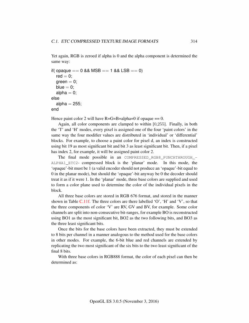
C.1. ETC COMPRESSED TEXTURE IMAGE FORMATS 314
Yet again, RGB is zeroed if alpha is 0 and the alpha component is determined thesame way:
if( opaque == 0 && MSB == 1 && LSB == 0)red = 0;green = 0;blue = 0;alpha = 0;
elsealpha = 255;
end
Hence paint color 2 will have R=G=B=alpha=0 if opaque == 0.Again, all color components are clamped to within [0,255]. Finally, in both
the ‘T’ and ‘H’ modes, every pixel is assigned one of the four ‘paint colors’ in thesame way the four modifier values are distributed in ‘individual’ or ‘differential’blocks. For example, to choose a paint color for pixel d, an index is constructedusing bit 19 as most significant bit and bit 3 as least significant bit. Then, if a pixelhas index 2, for example, it will be assigned paint color 2.
The final mode possible in an COMPRESSED_RGB8_PUNCHTHROUGH_-
ALPHA1_ETC2- compressed block is the ‘planar’ mode. In this mode, the‘opaque’-bit must be 1 (a valid encoder should not produce an ‘opaque’-bit equal to0 in the planar mode), but should the ‘opaque’-bit anyway be 0 the decoder shouldtreat it as if it were 1. In the ‘planar’ mode, three base colors are supplied and usedto form a color plane used to determine the color of the individual pixels in theblock.
All three base colors are stored in RGB 676 format, and stored in the mannershown in Table C.11f. The three colors are there labelled ‘O’, ‘H’ and ‘V’, so thatthe three components of color ‘V’ are RV, GV and BV, for example. Some colorchannels are split into non-consecutive bit-ranges, for example BO is reconstructedusing BO1 as the most significant bit, BO2 as the two following bits, and BO3 asthe three least significant bits.
Once the bits for the base colors have been extracted, they must be extendedto 8 bits per channel in a manner analogous to the method used for the base colorsin other modes. For example, the 6-bit blue and red channels are extended byreplicating the two most significant of the six bits to the two least significant of thefinal 8 bits.
With three base colors in RGB888 format, the color of each pixel can then bedetermined as:
OpenGL ES 3.0.5 (November 3, 2016)
C.1. ETC COMPRESSED TEXTURE IMAGE FORMATS 315
R(x, y) = x× (RH −RO)/4.0 + y × (RV −RO)/4.0 +ROG(x, y) = x× (GH −GO)/4.0 + y × (GV −GO)/4.0 +GOB(x, y) = x× (BH −BO)/4.0 + y × (BV −BO)/4.0 +BOA(x, y) = 255,
where x and y are values from 0 to 3 corresponding to the pixels coordinates withinthe block, x being in the u direction and y in the v direction. For example, the pixelg in Table C.2 would have x = 1 and y = 2.
These values are then rounded to the nearest integer (to the larger integer ifthere is a tie) and then clamped to a value between 0 and 255. Note that this isequivalent to
R(x, y) = clamp255((x× (RH −RO) + y × (RV −RO) + 4×RO + 2)� 2)G(x, y) = clamp255((x× (GH −GO) + y × (GV −GO) + 4×GO + 2)� 2)B(x, y) = clamp255((x× (BH −BO) + y × (BV −BO) + 4×BO + 2)� 2)A(x, y) = 255,
where clamp255 clamps the value to a number in the range [0, 255].Note that the alpha component is always 255 in the planar mode.This specification gives the output for each compression mode in 8-bit integer
colors between 0 and 255, and these values all need to be divided by 255 for thefinal floating point representation.
C.1.10 Format COMPRESSED_SRGB8_PUNCHTHROUGH_ALPHA1_ETC2
Decompression of floating point sRGB values in COMPRESSED_SRGB8_-
PUNCHTHROUGH_ALPHA1_ETC2 follows that of floating point RGB values ofCOMPRESSED_RGB8_PUNCHTHROUGH_ALPHA1_ETC2. The result is sRGB valuesbetween 0.0 and 1.0. The further conversion from an sRGB encoded component,cs, to a linear component, cl, is according to Equation 3.26. Assume cs is thesRGB component in the range [0,1]. Note that the alpha component is not gammacorrected, and hence does not use the above formula.
OpenGL ES 3.0.5 (November 3, 2016)
Appendix D
Shared Objects and MultipleContexts
This appendix describes special considerations for objects shared between multi-ple OpenGL ES contexts, including deletion behavior and how changes to sharedobjects are propagated between contexts.
Objects that can be shared between contexts include buffer objects, programand shader objects, renderbuffer objects, sync objects, sampler objects, and textureobjects (except for the texture objects named zero).
Framebuffer, query, transform feedback, and vertex array objects are notshared.
Implementations may allow sharing between contexts implementing differentOpenGL ES versions. However, implementation-dependent behavior may resultwhen aspects and/or behaviors of such shared objects do not apply to, and/or arenot described by more than one version or profile.
D.1 Object Deletion Behavior
D.1.1 Side Effects of Shared Context Destruction
The share list is the group of all contexts which share objects. If a shared objectis not explicitly deleted, then destruction of any individual context has no effecton that object unless it is the only remaining context in the share list. Once thelast context on the share list is destroyed, all shared objects, and all other resourcesallocated for that context or share list, will be deleted and reclaimed by the imple-mentation as soon as possible.
316
D.1. OBJECT DELETION BEHAVIOR 317
D.1.2 Automatic Unbinding of Deleted Objects
When a buffer, texture, or renderbuffer object is deleted, it is unbound from anybind points it is bound to in the current context, as described for DeleteBuffers,DeleteTextures, and DeleteRenderbuffers. Bind points in other contexts are notaffected. Attachments to unbound container objects, such as deletion of a bufferattached to a vertex array object which is not bound to the context, are not affectedand continue to act as references on the deleted object, as described in the followingsection.
D.1.3 Deleted Object and Object Name Lifetimes
When a buffer, texture, sampler, renderbuffer, query, or sync object is deleted, itsname immediately becomes invalid (e.g. is marked unused), but the underlyingobject will not be deleted until it is no longer in use. A buffer, texture, sampler, orrenderbuffer object is in use while it is attached to any container object (such as abuffer object attached to a vertex array object, or a renderbuffer or texture attachedto a framebuffer object) or bound to a context bind point in any context. A syncobject is in use while there is a corresponding fence command which has not yetcompleted and signaled the sync object, or while there are any GL clients and/orservers blocked on the sync object as a result of ClientWaitSync or WaitSynccommands. Query objects are in use so long as they are active, as described insection 2.14.
When a shader object or program object is deleted, it is flagged for deletion,but its name remains valid until the underlying object can be deleted because itis no longer in use. A shader object is in use while it is attached to any programobject. A program object is in use while it is the current program in any context.
Caution should be taken when deleting an object attached to a container object,or a shared object bound in multiple contexts. Following its deletion, the object’sname may be returned by Gen* commands, even though the underlying objectstate and data may still be referred to by container objects, or in use by contextsother than the one in which the object was deleted. Such a container or othercontext may continue using the object, and may still contain state identifying itsname as being currently bound, until such time as the container object is deleted,the attachment point of the container object is changed to refer to another object, oranother attempt to bind or attach the name is made in that context. Since the nameis marked unused, binding the name will create a new object with the same name,and attaching the name will generate an error. The underlying storage backing adeleted object will not be reclaimed by the GL until all references to the objectfrom container object attachment points or context binding points are removed.
OpenGL ES 3.0.5 (November 3, 2016)
D.2. SYNC OBJECTS AND MULTIPLE CONTEXTS 318
D.2 Sync Objects and Multiple Contexts
When multiple GL clients and/or servers are blocked on a single sync object andthat sync object is signalled, all such blocks are released. The order in which blocksare released is implementation-dependent.
D.3 Propagating Changes to Objects
GL objects contain two types of information, data and state. Collectively theseare referred to below as the contents of an object. For the purposes of propagatingchanges to object contents as described below, data and state are treated consis-tently.
Data is information the GL implementation does not have to inspect, and doesnot have an operational effect. Currently, data consists of:
• Pixels in the framebuffer.
• The contents of textures and renderbuffers.
• The contents of buffer objects.
State determines the configuration of the rendering pipeline and the driver doeshave to inspect.
In hardware-accelerated GL implementations, state typically lives in GPU reg-isters, while data typically lives in GPU memory.
When the contents of an object T are changed, such changes are not alwaysimmediately visible, and do not always immediately affect GL operations involvingthat object. Changes may occur via any of the following means:
• State-setting commands, such as TexParameter.
• Data-setting commands, such as TexSubImage* or BufferSubData.
• Data-setting through rendering to attached renderbuffers or transform feed-back operations.
• Commands that affect both state and data, such as TexImage* and Buffer-Data.
• Changes to mapped buffer data followed by a command such as Unmap-Buffer or FlushMappedBufferRange.
OpenGL ES 3.0.5 (November 3, 2016)
D.3. PROPAGATING CHANGES TO OBJECTS 319
D.3.1 Determining Completion of Changes to an object
The contents of an object T are considered to have been changed once a commandsuch as described in section D.3 has completed. Completion of a command 1 maybe determined either by calling Finish, or by calling FenceSync and executing aWaitSync command on the associated sync object. The second method does notrequire a round trip to the GL server and may be more efficient, particularly whenchanges to T in one context must be known to have completed before executingcommands dependent on those changes in another context.
D.3.2 Definitions
In the remainder of this section, the following terminology is used:
• An object T is directly attached to the current context if it has been bound toone of the context binding points. Examples include but are not limited tobound textures, bound framebuffers, bound vertex arrays, and current pro-grams.
• T is indirectly attached to the current context if it is attached to another ob-ject C, referred to as a container object, and C is itself directly or indirectlyattached. Examples include but are not limited to renderbuffers or texturesattached to framebuffers; buffers attached to vertex arrays; and shaders at-tached to programs.
• An object T which is directly attached to the current context may be re-attached by re-binding T at the same bind point. An object T which is indi-rectly attached to the current context may be re-attached by re-attaching thecontainer object C to which T is attached.
Corollary: re-binding C to the current context re-attaches C and its hierarchyof contained objects.
D.3.3 Rules
The following rules must be obeyed by all GL implementations:
Rule 1 If the contents of an object T are changed in the current context while T isdirectly or indirectly attached, then all operations on T will use the new contentsin the current context.
1The GL already specifies that a single context processes commands in the order they are received.This means that a change to an object in a context at time t must be completed by the time a commandissued in the same context at time t+ 1 uses the result of that change.
OpenGL ES 3.0.5 (November 3, 2016)
D.3. PROPAGATING CHANGES TO OBJECTS 320
Note: The intent of this rule is to address changes in a single context only. Themulti-context case is handled by the other rules.
Note: “Updates” via rendering or transform feedback are treated consistentlywith update via GL commands. Once EndTransformFeedback has been issued,any command in the same context that uses the results of the transform feedbackoperation will see the results. If a feedback loop is setup between rendering andtransform feedback (see above), results will be undefined.
Rule 2 While a container object C is bound, any changes made to the contents ofC’s attachments in the current context are guaranteed to be seen. To guaranteeseeing changes made in another context to objects attached to C, such changesmust be completed in that other context (see section D.3.1) prior to C being bound.Changes made in another context but not determined to have completed as de-scribed in section D.3.1, or after C is bound in the current context, are not guar-anteed to be seen.
Rule 3 Changes to the contents of shared objects are not automatically propa-gated between contexts. If the contents of a shared object T are changed in acontext other than the current context, and T is already directly or indirectly at-tached to the current context, any operations on the current context involving T viathose attachments are not guaranteed to use its new contents.
Rule 4 If the contents of an object T are changed in a context other than the cur-rent context, T must be attached or re-attached to at least one binding point in thecurrent context, or at least one attachment point of a currently bound containerobject C, in order to guarantee that the new contents of T are visible in the currentcontext.
Note: “Attached or re-attached” means either attaching an object to a bindingpoint it wasn’t already attached to, or attaching an object again to a binding pointit was already attached to.
Note: To be sure that a data update resulting from a transform-feedback opera-tion in another context is visible in the current context, the app needs to make surethat the command EndTransformFeedback has completed (see section D.3.1).
Example: If a texture image is bound to multiple texture bind points and thetexture is changed in another context, re-binding the texture at any one of the tex-ture bind points is sufficient to cause the changes to be visible at all texture bindpoints.
OpenGL ES 3.0.5 (November 3, 2016)
Appendix E
Version 3.0 and Before
OpenGL ES version 3.0, released on August 6, 2012, is the third revision sincethe original version 1.0. OpenGL ES 3.0 is upward compatible with OpenGL ESversion 2.0, meaning that any program that runs with an OpenGL ES 2.0 imple-mentation will also run unchanged with an OpenGL ES 3.0 implementation. Notethe subtle changes in runtime behavior between versions 2.0 and 3.0, documentedin Appendix F.2.
Following are brief descriptions of changes and additions to OpenGL ES 3.0.
E.1 New Features
New features in OpenGL ES 3.0 include:
• OpenGL Shading Language ES 3.00
• transform feedback 1 and 2 (with restrictions)
• uniform buffer objects including block arrays
• vertex array objects
• sampler objects
• sync objects and fences
• pixel buffer objects
• buffer subrange mapping
• buffer object to buffer object copies
321
E.1. NEW FEATURES 322
• boolean occlusion queries, including conservative mode
• instanced rendering, via shader variable and/or vertex attribute divisor
• multiple render targets
• 2D array and 3D textures
• simplified texture storage specification
• R and RG textures
• texture swizzles
• seamless cube maps
• non-power-of-two textures with full wrap mode support and mipmapping
• texture LOD clamps and mipmap level base offset and max clamp
• at least 32 textures, at least 16 each for fragment and vertex shaders
• 16-bit (with filtering) and 32-bit (without filtering) floating-point textures
• 32-bit, 16-bit, and 8-bit signed and unsigned integer renderbuffers, textures,and vertex attributes
• 8-bit sRGB textures and framebuffers (without mixed RGB/sRGB render-ing)
• 11/11/10 floating-point RGB textures
• shared exponent RGB 9/9/9/5 textures
• 10/10/10/2 unsigned normalized and unnormalized integer textures
• 10/10/10/2 signed and unsigned normalized vertex attributes
• 16-bit floating-point vertex attributes
• 8-bit-per-component signed normalized textures
• ETC2/EAC texture compression formats
• sized internal texture formats with minimum precision guarantees
• multisample renderbuffers
OpenGL ES 3.0.5 (November 3, 2016)
E.2. CHANGE LOG FOR 3.0.5, NOVEMBER 3, 2016 323
• 8-bit unsigned normalized renderbuffers
• depth textures and shadow comparison
• 24-bit depth renderbuffers and textures
• 24/8 depth/stencil renderbuffers and textures
• 32-bit depth and 32F/8 depth/stencil renderbuffers and textures
• stretch blits (with restrictions)
• framebuffer invalidation hints
• primitive restart with fixed index
• unsigned integer element indices with at least 24 usable bits
• draw command allowing specification of range of accessed elements
• ability to attach any mipmap level to a framebuffer object
• minimum/maximum blend equations
• program binaries, including querying binaries from linked GLSL programs
• mandatory online compiler
• non-square and transposable uniform matrices
• additional pixel store state
• indexed extension string queries
E.2 Change Log for 3.0.5, November 3, 2016
Changes since the 3.0.4 specification:
• Remove unusable bool and bvec* types from table 2.11 (Bug 15023).
• Clean up LinkProgram link failure list in section 2.12.3 and add a missingerror when no shader objects are attached (Bug 13841).
OpenGL ES 3.0.5 (November 3, 2016)
E.3. CHANGE LOG FOR 3.0.4 324
• Specify that the COLOR_ATTACHMENTm tokens are defined for m in therange [0, 31] in section 4.4.1, and specify that INVALID_OPERATION errorsare generated for valid COLOR_ATTACHMENTm tokens where m is outsidethe range of valid color attachments for the commands GetFramebufferAt-tachmentParameteriv (section 6.1.13), FramebufferRenderbuffer (sec-tion 4.4.2.3), FramebufferTexture2D (section 4.4.2.4), DrawBuffers (sec-tion 4.2.1), InvalidateSubFramebuffer (section 4.5), and ReadBuffer (sec-tion 4.3.1. Also, update some of chapter 4 to use error language and phras-ing based on the restructured OpenGL ES 3.2 Specification (Bugs 13858 /15784).
• Cleanup description of levelbase and levelmax in sections 3.8.7 and 3.8.10.4(Bugs 15813 / 15824).
E.3 Change Log for 3.0.4
Changes since the 3.0.3 specification:
• Update description of internal format determination for CopyTexImage2D(Bug 9807).
• Clarify behavior of rendering to multiple attachments of different sizes, andclarify what constitutes a rendering command (Bug 10403).
• Relax spec language governing rounding of the texture coordinate used toselect the layer of an array texture (Bug 11399).
• Change query command in table 6.12 for DEPTH_CLEAR_VALUE to glGet-Floatv (Bug 11456).
• Change value of UNIFORM_BUFFER_OFFSET_ALIGNMENT in table 6.33 to256, and make clear that this is a maximum alignment value, not minimum(Bug 11962).
E.4 Change Log for 3.0.3
Changes since the 3.0.2 specification:
• Remove ”non-64-bit” from first sentence of section 6.1.2 (Bug 7895).
• Remove redundant reference to setting TEXTURE_IMMUTABLE_FORMAT andTEXTURE_IMMUTABLE_LEVELS from the end of section 3.8.4 (Bug 9342).
OpenGL ES 3.0.5 (November 3, 2016)
E.4. CHANGE LOG FOR 3.0.3 325
• Clarify framebuffer attachment completeness rules with respect to theFRAMEBUFFER_ATTACHMENT_TEXTURE_LEVEL and mipmap complete-ness (Bug 9689).
• Clarify active uniform enumeration rules (Bug 9797).
• Clarify behavior of mipmap completeness with unsized base internal formats(Bug 9807).
• Introduce INVALID_VALUE error when BindBufferRange is called with anegative offset (Bug 9873).
• Clarify that when DrawBuffers is called with 0 as the value of n, in the de-fault framebuffer case INVALID_OPERATION is generated, and in the frame-buffer object case, NONE is assigned to all draw buffers (Bug 10059).
• Allow alternate formulation of equation 3.21’s mipmap array selection (Bug10119).
• Untangle ReadBuffer from ReadPixels and put it into its own section, whileclarifying the error conditions (Bug 10172).
• Specify that std140 and shared layout uniform blocks and their membersare always active (Bug 10182).
• Introduce missing INVALID_OPERATION error when BindAttribLocationis called with a name that starts with the reserved "gl_" prefix (Bug 10271).
• Clarify return values from GetFramebufferAttachmentParameteriv ofNONE and LINEAR for FRAMEBUFFER_ATTACHMENT_COMPONENT_TYPE
and FRAMEBUFFER_ATTACHMENT_COLOR_ENCODING, respectively, whenthe attachment has not been initialized (Bug 10357).
• Fix description of fragment shader outputs to only require explicit outputvariable bindings to fragment colors when there are more than one outputvariable (Bug 10363).
• Clarify that ValidateProgram is only required to check for the errors de-scribed in the Validation section, not all INVALID_OPERATION errors thatcan be generated by rendering commands (Bug 10650).
• Clarify behavior of commands that don’t specify whether an error is gener-ated when accessing a mapped buffer object (Bug 10684).
OpenGL ES 3.0.5 (November 3, 2016)
E.5. CHANGE LOG FOR 3.0.2 326
• Clarify that SAMPLE_BUFFERS and SAMPLES are framebuffer-dependentstate, and that SAMPLE_BUFFERS can only assume the values zero or one(Bug 10689).
• Simplify description of multisample rasterization to specify it is in effectwhen SAMPLE_BUFFERS is one, eliminating extraneous language about GLcontexts, EGL, etc. (Bug 10690).
• Clarify the type of stencil bits in table 3.14 (Bug 10748).
• Clarify that writing different color values to the same image attached multi-ple times is undefined (Bug 10983).
• Clean up description of FRAMEBUFFER_ATTACHMENT_TEXTURE_LAYER
query (Bug 11199).
• Clarify that samplers behave the same as textures, renderbuffers, and bufferswith respective to object name lifetimes (Bug 11374).
E.5 Change Log for 3.0.2
Changes since the 3.0.1 specification:
• Clarify BlitFramebuffer downsampling behavior for different types of sam-ples (Bug 9690).
• Clarify that program object state queries return the state presently in effect,which may be different than most recently set state (Bug 9702).
• Clarify that current vertex attributes are not program object state (Bug 9781).
• Clarify that integer state is undefined when set with out-of-range floating-point values (Bug 9846).
• Clarify that Draw* commands are silently ignored when there is no currentprogram object, rather than it being an error condition (Bug 9879).
• Clarify that texel fetches are undefined when texel coordinates fall outsidethe computed level of detail, not the specified level of detail (Bug 9891).
• Clarify which pixels are read and written by BlitFramebuffer (Bug 9946).
• Clarify that either truncation or rounding are acceptable when convertingfrom floating-point to normalized fixed-point (Bug 9976).
OpenGL ES 3.0.5 (November 3, 2016)
E.6. CHANGE LOG FOR 3.0.1 327
• Make the minification vs. magnification switch-over point always zero (Bug9997).
• Clarify that DrawArrays transfers no elements when count is zero (Bug10015).
• Tweak the language covering the conditions that can affect framebuffer com-pleteness (Bug 10047).
• Remove language in Appendix D that preserves binding-related state afteran object is deleted and automatically unbound (Bug 10076).
• Remove language in Appendix D that implies that active transform feedbackobjects can be deleted (Bug 10079).
E.6 Change Log for 3.0.1
Changes since the 3.0.0 specification:
• Remove the clamp on reference value for shadow maps with floating-pointdepth formats (Bug 7975).
• Clarify GetFramebufferAttachmentParameteriv behavior for a few dif-ferent cases (Bug 9170).
• Move description of level base and level max clamping for immutable tex-tures to Mipmapping section (Bug 9342).
• Remove references to floating-point formats when describing BlitFrame-buffer (Bug 9388).
• Remove PACK_IMAGE_HEIGHT and PACK_SKIP_IMAGES which have noeffect (Bug 9414).
• Require that Invalidate[Sub]Framebuffer accept DRAW_FRAMEBUFFER
and READ_FRAMEBUFFER (Bug 9421).
• Fix initial value of read buffer to be NONE if there is no default framebufferassociated with the context (Bug 9473).
• Require that Invalidate[Sub]Framebuffer accept DEPTH_STENCIL_-
ATTACHMENT (Bug 9480).
OpenGL ES 3.0.5 (November 3, 2016)
E.6. CHANGE LOG FOR 3.0.1 328
• Require that GenerateMipmap throw INVALID_OPERATION for depth tex-tures (Bug 9481).
• Clarify that a texture is incomplete if it has a depth component, no shadowcomparison, and linear filtering (also Bug 9481).
• Minor tweaks to description of RGB9_E5 (Bug 9486).
• Clarify behavior when drawing to an FBO with both NULL and non-NULLattachments (Bug 9494).
• Clarify behavior of BindBufferBase (Bug 9513).
• Return to a clamp-on-specification behavior for ClearDepth andDepthRange (Bug 9517).
• Eliminate references to programs without fragment shaders (Bug 9543).
• Move some uniform buffer state out of program object state tables (Bug9566).
• Clarify that gl_VertexID is undefined if any client-side vertex arrays areenabled (Bug 9603).
• Clarify that vertex attribute aliasing is not permitted in conjunction withGLSL-ES 3.00 shaders (Bug 9609).
• Fix description of LINK_STATUS which was incorrectly specified to returnthe compilation status (Bug 9698).
• Clarifications and clean up in query object language (Bug 9766).
• Clarify that mask may be zero for BlitFramebuffer indicating no action betaken (Bug 9748).
• Clarify that arguments to TexSubImage* need not exactly match the valuespassed to TexImage* (Bug 9750).
• Clarify that BindBufferRange only performs error checking of size and off-set if buffer is not zero (Bug 9765).
• Fix minor typos and other minor tweaks to transform feedback description(Bug 9842).
• Clarify that primitives collected with transform feedback must match (notmerely be compatible with) the transform feedback primitiveMode.
OpenGL ES 3.0.5 (November 3, 2016)
E.7. CREDITS AND ACKNOWLEDGEMENTS 329
• Clarify that only thespecified portion(s) (depth and/or stencil) of depth/stencil attachment maybe invalidated by Invalidate[Sub]Framebuffer.
• Remove references to FLOAT in table 3.14.
• Cleaned up index entries for state tables 6.13 and 6.35 which were overlyverbose.
• Added individual bookmarks to each state table in the PDF.
E.7 Credits and Acknowledgements
OpenGL ES 3.0 is the result of the contributions of many people and companies.Members of the Khronos OpenGL ES Working Group during the development ofOpenGL ES 3.0, including the company that they represented at the time of theircontributions, follow. In addition, many people participated in developing desktopOpenGL specifications and extensions on which the OpenGL ES 3.0 functionalityis based in large part; those individuals are listed in the respective specifications inthe OpenGL Registry.
Acorn Pooley, NVIDIAAlberto Moreira, QualcommAleksandra Krstic, QualcommAlex Eddy, AppleAlon Or-Bach, NokiaAndrzej Kacprowski, IntelArzhange Safdarzadeh, IntelAske Simon Christensen, ARMAvi Shapira, Graphic RemedyBarthold Lichtenbelt, NVIDIABen Bowman, Imagination TechnologiesBen Brierton, BroadcomBenj Lipchak, AppleBenson Tao, VivanteBill Licea-Kane, AMDBrent Insko, IntelBrian Murray, FreescaleBruce Merry, ARMCarlos Santa, TICass Everitt, Epic Games & NVIDIACemil Azizoglu, TIChang-Hyo Yu, SamsungChris Dodd, NVIDIAChris Knox, NVIDIA
Chris Tserng, TIClay Montgomery, TICliff Gibson, Imagination TechnologiesDaniel Kartch, NVIDIADaniel Koch, TransgamingDaoxiang Gong, Imagination TechnologiesDave Shreiner, ARMDavid Garcia, AMDDavid Jarmon, VivanteDerek Cornish, Epic GamesDominik Witczak, ARM & MobicaEben Upton, BroadcomEd Plowman, Intel & ARMEisaku Ohbuchi, DMPElan Lennard, ARMErik Faye-Lund, ARMGeorg Kolling, Imagination TechnologiesGraeme Leese, BroadcomGraham Connor, Imagination TechnologiesGraham Sellers, AMDGreg Roth, NVIDIAGuillaume Portier, HiGuofang Jiao, QualcommHans-Martin Will, Vincent
OpenGL ES 3.0.5 (November 3, 2016)
E.7. CREDITS AND ACKNOWLEDGEMENTS 330
Hwanyong Lee, HuoneI-Gene Leong, NVIDIAIan Romanick, IntelIan South-Dickinson, NVIDIAIlan Aelion-Exch, SamsungInkyun Lee, HuoneJacob Strom, EricssonJames Adams, BroadcomJames Jones, Imagination TechnologiesJames McCombe, Imagination TechnologiesJamie Gennis, GoogleJan-Harald Fredriksen, ARMJani Vaisanen, NokiaJarkko Kemppainen, SymbioJauko Kylmaoja, SymbioJeff Bolz, NVIDIAJeff Leger, QualcommJeff Vigil, QualcommJeremy Sandmel, AppleJeremy Thorne, BroadcomJim Hauxwell, BroadcomJinsung Kim, HuoneJiyoung Yoon, HuoneJon Kennedy, 3DLabsJon Leech, KhronosJonathan Putsman, Imagination TechnologiesJørn Nystad, ARMJussi Rasanen, NVIDIAKalle Raita, drawElementsKari Pulli, NokiaKeith Whitwell, VMwareKent Miller, Netlogic MicrosystemsKimmo Nikkanen, NokiaKonsta Karsisto, NokiaKrzysztof Kaminski, IntelKyle Haughey, AppleLarry Seiler, IntelLars Remes, SymbioLee Thomason, AdobeLefan Zhong, VivanteLuc Semeria, AppleMarcus Lorentzon, EricssonMark Butler, Imagination TechnologiesMark Callow, HiMark Cresswell, BroadcomMark Snyder, Alt SoftwareMark Young, AMDMathieu Robart, STMMatt Russo, Matrox
Matthew Netsch, QualcommMaurice Ribble, AMD & QualcommMax Kazakov, DMPMika Pesonen, NokiaMike Cai, VivanteMike Weiblen, Zebra ImagingMila Smith, AMDNakhoon Baek, Kyungpook UniveristyNate Huang, NVIDIANeil Trevett, NVIDIANelson Kidd, IntelNick Haemel, AMD & NVIDIANick Penwarden, Epic GamesNiklas Smedberg, Epic GamesNizar Romdan, ARMOliver Wohlmuth, FujitsuPat Brown, NVIDIAPaul Ruggieri, QualcommPaul Wilkinson, BroadcomPer Wennersten, EricssonPetri Talalla, SymbioPhil Huxley, ZiiLabsPhilip Hatcher, FreescalePiers Daniell, NVIDIAPiotr Tomaszewski, EricssonPiotr Uminski, IntelRami Mayer, SamsungRauli Laatikainen, RightWareRichard Schreyer, AppleRob Barris, NVIDIARob Simpson, QualcommRobert Simpson, AMDRoj Langhi, VivanteRune Holm, ARMSami Kyostila, NokiaScott Bassett, AppleSean Ellis, ARMShereef Shehata, TISila Kayo, NokiaSlawomir Grajewski, IntelSteve Hill, STM & BroadcomSteven Olney, DMPSuman Sharma, IntelTapani Palli, NokiaTeemu Laakso, SymbioTero Karras, NVIDIATimo Suoranta, Imagination TechnologiesTom Cooksey, ARMTom McReynolds, NVIDIA
OpenGL ES 3.0.5 (November 3, 2016)
E.7. CREDITS AND ACKNOWLEDGEMENTS 331
Tom Olson, TI & ARMTomi Aarnio, NokiaTommy Asano, Takumi
Wes Bang, NokiaYanjun Zhang, VivanteYuan Wang, Imagination Technologies
The OpenGL ES Working Group gratefully acknowledges administrative sup-port by the members of Gold Standard Group, including Andrew Riegel, ElizabethRiegel, Glenn Fredericks, and Michelle Clark, and technical support from JamesRiordon, webmaster of Khronos.org and OpenGL.org.
OpenGL ES 3.0.5 (November 3, 2016)
Appendix F
OpenGL ES 2.0 Compatibility
The OpenGL ES 3.0 API is backward compatible with OpenGL ES 2.0. It acceptsall of the same commands and their arguments, including the same token values.This appendix describes OpenGL ES 3.0 features that were carried forward fromOpenGL ES 2.0 solely to maintain backward compatibility as well as those thathave changed in behavior relative to OpenGL ES 2.0.
F.1 Legacy Features
The following features are present to maintain backward compatibility withOpenGL ES 2.0, but their use in not recommended as it is likely for these featuresto be removed in a future version.
• Fixed-point (16.16) vertex attributes
• Application-chosen object names (those not generated via Gen* or Create*)
• Client-side vertex arrays (those not stored in buffer objects)
• Luminance, alpha, and luminance alpha formats
• Queryable shader range and precision (GetShaderPrecisionFormat)
• Old-style non-indexed extensions query
• Vector-wise uniform limits
• Default vertex array object
332
F.2. DIFFERENCES IN RUNTIME BEHAVIOR 333
F.2 Differences in Runtime Behavior
The following behaviors are different in OpenGL ES 3.0 than they were in OpenGLES 2.0.
• OpenGL ES 3.0 requires that all cube map filtering be seamless. OpenGL ES2.0 specified that a single cube map face be selected and used for filtering.See section 3.8.9.1.
• OpenGL ES 3.0 specifies a zero-preserving mapping when converting backand forth between signed normalized fixed-point values and floating-pointvalues. OpenGL ES 2.0 specified a mapping by which zeros are not pre-served. See section 2.1.6.
• OpenGL ES 3.0 requires that framebuffer objects not be shared between con-texts. OpenGL ES 2.0 left it undefined whether framebuffer objects could beshared. See appendix D.
OpenGL ES 3.0.5 (November 3, 2016)
Index
x BITS, 280
ACTIVE ATTRIBUTE MAX -LENGTH, 56, 236, 264
ACTIVE ATTRIBUTES, 55, 56, 236,263
ACTIVE TEXTURE, 122, 124, 228,253
ACTIVE UNIFORM BLOCK -MAX NAME LENGTH, 237,265
ACTIVE UNIFORM BLOCKS, 60,237, 265
ACTIVE UNIFORM MAX LENGTH,62, 236, 263
ACTIVE UNIFORMS, 61, 62, 236, 263ActiveTexture, 72, 122, 122ADDED ERRORS SECTION, 185,
206, 208, 219, 243ALIASED LINE WIDTH RANGE,
99, 273ALIASED POINT SIZE RANGE, 98,
273ALPHA, 113, 115, 127, 128, 139, 142,
150, 163, 167, 168, 181, 254,259, 280
ALPHA BITS, 217ALREADY SIGNALED, 224ALWAYS, 149, 164, 176, 177, 256ANY SAMPLES PASSED, 84, 177,
178, 231
ANY SAMPLES PASSED CONSER-VATIVE, 84, 177, 178, 231
ARRAY BUFFER, 25, 33, 42ARRAY BUFFER BINDING, 42, 248ATTACHED SHADERS, 236, 237, 263AttachShader, 48
BACK, 105, 176, 184–187, 191, 241,243, 251
BeginQuery, 84, 84, 91, 177BeginTransformFeedback, 87, 87–89BindAttribLocation, 54, 56, 57, 325BindBuffer, 32, 32–34, 43BindBufferBase, 34, 35, 71, 88, 91, 234,
328BindBufferRange, 34, 35, 71, 88, 89,
91, 325, 328BindFramebuffer, 200, 200, 202, 215BindRenderbuffer, 203, 203, 204BindSampler, 124, 124, 125BindTexture, 72, 122, 123, 123BindTransformFeedback, 86, 86, 87BindVertexArray, 44, 44BLEND, 178, 256BLEND COLOR, 256BLEND DST ALPHA, 256BLEND DST RGB, 256BLEND EQUATION ALPHA, 256BLEND EQUATION RGB, 256BLEND SRC ALPHA, 256BLEND SRC RGB, 256BlendColor, 180, 182
334
INDEX 335
BlendEquation, 178, 179BlendEquationSeparate, 178, 179BlendFunc, 180, 180BlendFuncSeparate, 180, 180BlitFramebuffer, 19, 97, 190, 196, 196,
198, 326–328BLUE, 150, 163, 167, 254, 259, 280BLUE BITS, 217BOOL, 63bool, 63, 68, 90, 323BOOL VEC2, 63BOOL VEC3, 63BOOL VEC4, 63BUFFER ACCESS FLAGS, 34, 36, 39,
40, 249BUFFER MAP LENGTH, 34, 36, 39,
40, 249BUFFER MAP OFFSET, 34, 36, 39,
40, 249BUFFER MAP POINTER, 34, 36, 39,
40, 233, 249BUFFER MAPPED, 34, 36, 39, 40, 249BUFFER SIZE, 34, 36, 37, 39, 249BUFFER USAGE, 34, 36, 38, 249BufferData, 35, 36, 41, 59, 318BufferSubData, 37, 59, 318bvec*, 323bvec2, 63, 66, 90bvec3, 63, 90bvec4, 63, 90BYTE, 24, 26, 111, 112, 114, 195
CCW, 105, 251centroid in, 166CheckFramebufferStatus, 215, 216, 216CLAMP TO EDGE, 150, 152, 156, 197Clear, 19, 96, 187, 188–190ClearBuffer, 189, 190ClearBuffer*, 96ClearBuffer{if ui}v, 189
ClearBufferfi, 189, 189, 190ClearBufferfv, 189, 190ClearBufferiv, 189, 190ClearBufferuiv, 189, 190ClearColor, 188ClearDepth, 328ClearDepthf, 188ClearStencil, 188ClientWaitSync, 222, 223, 223–225,
317COLOR, 189, 190, 220COLOR ATTACHMENTm, 324COLOR ATTACHMENT0, 186, 191,
201COLOR BUFFER BIT, 188, 190, 196,
197COLOR CLEAR VALUE, 257COLOR WRITEMASK, 257ColorMask, 186, 186, 187COMPARE REF TO TEXTURE, 149,
163COMPILE STATUS, 46, 48, 235, 262CompileShader, 46, 46, 47, 170COMPRESSED R11 EAC, 147, 289,
301, 303, 304COMPRESSED RG11 EAC, 147, 289,
304COMPRESSED RGB8 ETC2, 147,
288–292, 295, 297–299COMPRESSED RGB8 -
PUNCHTHROUGH AL-PHA1 ETC2, 147, 289, 291,308, 312, 314, 315
COMPRESSED RGBA8 ETC2 EAC,147, 288, 291, 298, 299, 301,303, 304
COMPRESSED SIGNED R11 EAC,147, 289, 305, 308
COMPRESSED SIGNED RG11 EAC,147, 289, 308
OpenGL ES 3.0.5 (November 3, 2016)
INDEX 336
COMPRESSED SRGB8 AL-PHA8 ETC2 EAC, 147, 164,288, 289, 291, 301
COMPRESSED SRGB8 ALPHA8 -ETC2 EAC, 301
COMPRESSED SRGB8 ETC2, 147,164, 288, 291, 298
COMPRESSED SRGB8 -PUNCHTHROUGH AL-PHA1 ETC2, 147, 164, 289,291, 315
COMPRESSED TEXTURE FOR-MATS, 146, 274
CompressedTexImage, 148CompressedTexImage*, 136, 138, 215CompressedTexImage2D, 146, 147,
148, 289CompressedTexImage3D, 146, 147, 148CompressedTexSubImage*, 149CompressedTexSubImage2D, 147, 148,
290CompressedTexSubImage3D, 147, 148CONDITION SATISFIED, 224CONSTANT ALPHA, 181CONSTANT COLOR, 181COPY READ BUFFER, 33, 41COPY READ BUFFER BINDING,
281COPY WRITE BUFFER, 33, 41COPY WRITE BUFFER BINDING,
281CopyBufferSubData, 41CopyTex*, 127, 140CopyTexImage, 140, 217CopyTexImage*, 138, 207, 212, 215CopyTexImage2D, 139, 141, 143, 145,
158, 324CopyTexImage3D, 143CopyTexSubImage, 217CopyTexSubImage*, 207
CopyTexSubImage2D, 143, 143–145CopyTexSubImage3D, 143, 143–145Create*, 332CreateProgram, 48CreateShader, 45CULL FACE, 105, 251CULL FACE MODE, 251CullFace, 105, 105, 108CURRENT PROGRAM, 263CURRENT QUERY, 231, 281CURRENT VERTEX ATTRIB, 239,
267CW, 105
DECR, 176DECR WRAP, 176DELETE STATUS, 47, 235, 236, 262,
263DeleteBuffers, 32, 33, 41, 317DeleteFramebuffers, 201DeleteProgram, 53, 53DeleteQueries, 84, 85DeleteRenderbuffers, 203, 215, 317DeleteSamplers, 124, 125DeleteShader, 47, 47DeleteSync, 223, 223, 233DeleteTextures, 123, 215, 317DeleteTransformFeedbacks, 86, 86, 87DeleteVertexArrays, 44, 44DEPTH, 189, 190, 220, 241, 243, 259DEPTH24 STENCIL8, 112, 129, 133DEPTH32F STENCIL8, 112, 129, 133DEPTH ATTACHMENT, 201, 206,
214, 219DEPTH BITS, 217, 280DEPTH BUFFER BIT, 188, 190, 196–
198DEPTH CLEAR VALUE, 257, 324DEPTH COMPONENT, 78, 112, 115,
127, 133, 163, 168, 193
OpenGL ES 3.0.5 (November 3, 2016)
INDEX 337
DEPTH COMPONENT16, 112, 129,133
DEPTH COMPONENT24, 112, 129,133
DEPTH COMPONENT32F, 112, 129,133
DEPTH FUNC, 256DEPTH RANGE, 250DEPTH STENCIL, 78, 112, 115, 117,
120, 121, 127, 133, 160, 163,168, 189, 190, 193, 206, 210,213, 219
DEPTH STENCIL ATTACHMENT,206, 210, 219, 241, 243, 327
DEPTH TEST, 177, 256DEPTH WRITEMASK, 257DepthFunc, 177DepthMask, 186, 187DepthRange, 328DepthRangef, 82, 228DetachShader, 48dFdx, 226dFdy, 226Disable, 27, 96, 105, 108, 174, 175, 177,
178, 183DisableVertexAttribArray, 26, 239DITHER, 183, 256DONT CARE, 226, 272Draw*, 326DRAW BUFFERi, 186, 189, 258DRAW FRAMEBUFFER, 199, 200,
202, 205–208, 216, 219, 241,243, 257, 327
DRAW FRAMEBUFFER BIND-ING, 157, 184, 185, 198, 202,216–218, 257
DrawArrays, 19, 27, 29, 29, 42, 44, 78,88, 89
DrawArraysInstanced, 26, 29, 30, 88,89
DrawArraysOneInstance, 28, 28DrawBuffers, 184, 184–187, 190, 324,
325DrawElements, 27, 30, 30, 31, 42–44,
88DrawElementsInstanced, 26, 27, 30, 42,
43, 88DrawElementsOneInstance, 29, 29, 30DrawRangeElements, 27, 31, 42, 43,
88, 274DST ALPHA, 181DST COLOR, 181DYNAMIC COPY, 34, 36DYNAMIC DRAW, 34, 36DYNAMIC READ, 34, 36
ELEMENT ARRAY BUFFER, 33, 42,43
ELEMENT ARRAY BUFFER BIND-ING, 247
Enable, 27, 96, 105, 108, 174, 175, 177,178, 183, 228
EnableVertexAttribArray, 26, 44, 239EndQuery, 84, 85, 177EndTransformFeedback, 87, 87, 91, 320EQUAL, 149, 164, 176, 177EXTENSIONS, 230, 231, 275
FALSE, 14, 34, 36, 40, 41, 46, 49, 52–54, 58, 66, 79–81, 85, 162,163, 169, 175, 178, 228, 229,231, 233–236, 239, 240, 243,247–249, 251, 252, 254, 256,262, 263, 268, 269, 281
FASTEST, 226FenceSync, 222, 222, 223, 226, 319Finish, 221, 221, 222, 286, 319FIRST VERTEX CONVENTION, 92FIXED, 24, 25flat, 92
OpenGL ES 3.0.5 (November 3, 2016)
INDEX 338
FLOAT, 24, 25, 31, 56, 63, 111, 112,114, 194, 195, 241, 247, 329
float, 55, 63, 68, 90FLOAT 32 UNSIGNED INT -
24 8 REV, 112–114, 116, 117,119
FLOAT MAT2, 56, 63FLOAT MAT2x3, 56, 63FLOAT MAT2x4, 56, 63FLOAT MAT3, 56, 63FLOAT MAT3x2, 56, 63FLOAT MAT3x4, 56, 63FLOAT MAT4, 56, 63FLOAT MAT4x2, 56, 63FLOAT MAT4x3, 56, 63FLOAT VEC2, 56, 63FLOAT VEC3, 56, 63FLOAT VEC4, 56, 63Flush, 221, 225, 286FlushMappedBufferRange, 38, 39, 40,
40, 318FRAGMENT SHADER, 165, 235, 238FRAGMENT SHADER DERIVA-
TIVE HINT, 226, 272FRAMEBUFFER, 200, 205–208, 216,
219, 241, 243FRAMEBUFFER ALPHA SIZE, 141FRAMEBUFFER ATTACHMENT x -
SIZE, 259FRAMEBUFFER ATTACHMENT -
ALPHA SIZE, 241FRAMEBUFFER ATTACHMENT -
BLUE SIZE, 241FRAMEBUFFER ATTACHMENT -
COLOR ENCODING,139, 179, 182, 197, 242, 259,325
FRAMEBUFFER ATTACHMENT -COMPONENT TYPE, 241,243, 259, 325
FRAMEBUFFER ATTACHMENT -DEPTH SIZE, 241
FRAMEBUFFER ATTACHMENT -ENCODING, 141
FRAMEBUFFER ATTACHMENT -GREEN SIZE, 241
FRAMEBUFFER ATTACH-MENT OBJECT NAME, 206,209, 213, 214, 241–243, 259
FRAMEBUFFER ATTACH-MENT OBJECT TYPE, 206,209, 213, 217, 241–243, 259
FRAMEBUFFER ATTACHMENT -RED SIZE, 241
FRAMEBUFFER ATTACHMENT -STENCIL SIZE, 241
FRAMEBUFFER ATTACHMENT -TEXTURE -CUBE MAP FACE, 209, 242,259
FRAMEBUFFER ATTACHMENT -TEXTURE LAYER, 209, 213,218, 242, 259, 326
FRAMEBUFFER ATTACHMENT -TEXTURE LEVEL, 157, 209,211, 213, 214, 242, 259, 325
FRAMEBUFFER BINDING, 202FRAMEBUFFER BLUE SIZE, 141FRAMEBUFFER COMPLETE, 216FRAMEBUFFER DEFAULT, 241FRAMEBUFFER GREEN SIZE, 141FRAMEBUFFER INCOMPLETE AT-
TACHMENT, 214FRAMEBUFFER INCOMPLETE DI-
MENSIONS, 214FRAMEBUFFER INCOMPLETE -
MISSING ATTACHMENT,214
FRAMEBUFFER INCOMPLETE -MULTISAMPLE, 215
OpenGL ES 3.0.5 (November 3, 2016)
INDEX 339
FRAMEBUFFER RED SIZE, 141FRAMEBUFFER UNDEFINED, 214FRAMEBUFFER UNSUPPORTED,
214, 215FramebufferRenderbuffer, 205, 205,
206, 215, 324FramebufferTexture*, 209, 210, 215FramebufferTexture2D, 207, 208, 209,
324FramebufferTextureLayer, 208, 209FRONT, 105, 176, 187FRONT AND BACK, 105, 176, 187FRONT FACE, 251FrontFace, 104, 105, 169FUNC ADD, 179, 180, 182, 256FUNC REVERSE SUBTRACT, 179,
180FUNC SUBTRACT, 179, 180fwidth, 226
Gen*, 317, 332GenBuffers, 32, 32GENERATE MIPMAP HINT, 226,
272GenerateMipmap, 159, 328GenFramebuffers, 199, 199, 202GenQueries, 84, 84, 85GenRenderbuffers, 203, 203, 204GenSamplers, 124, 124–126, 229GenTextures, 122, 123GenTransformFeedbacks, 86, 86, 87GenVertexArrays, 43, 43, 44GEQUAL, 149, 164, 176, 177Get, 83, 227, 228GetActiveAttrib, 56, 75, 264GetActiveUniform, 50, 59, 62, 62–64,
67, 263GetActiveUniformBlockiv, 60, 266GetActiveUniformBlockName, 50, 60
GetActiveUniformsiv, 62, 62, 64, 265,266
GetAttachedShaders, 237, 263GetAttribLocation, 51, 56, 56, 57, 264GetBooleanv, 175, 227, 228, 245, 252,
257, 269, 274GetBufferParameteri64v, 233, 249GetBufferParameteriv, 233, 249GetBufferPointerv, 233, 233, 249GetError, 17, 17, 281GetFloatv, 12, 175, 227, 228, 245, 250–
252, 256, 257, 273GetFragDataLocation, 51, 170GetFramebufferAttachmentParameteriv,
217, 240, 241, 259, 324, 325,327
GetInteger64i v, 227, 234, 269, 270GetInteger64v, 30, 61, 224, 227, 228,
245, 273, 274, 278GetIntegeri v, 227, 234, 269, 270GetIntegerv, 31, 68, 71, 97, 125, 185,
186, 191, 193, 202, 203, 227,228, 230, 245, 247, 248, 250,251, 253, 256–258, 261, 263,269, 270, 272–281
GetInternalformativ, 204, 244GetProgramBinary, 53, 53, 54, 263GetProgramInfoLog, 52, 54, 237, 263GetProgramiv, 49, 53–56, 60, 61, 74,
75, 79, 236, 236, 237, 263–265GetQueryiv, 231, 281GetQueryObjectuiv, 231, 232, 268GetRenderbufferParameteriv, 217, 243,
244, 260GetSamplerParameter, 229, 255GetSamplerParameter*, 124, 229GetSamplerParameterfv, 255GetSamplerParameteriv, 255GetShaderInfoLog, 46, 237, 262GetShaderiv, 46, 47, 235, 237, 238, 262
OpenGL ES 3.0.5 (November 3, 2016)
INDEX 340
GetShaderPrecisionFormat, 47, 238,274, 332
GetShaderSource, 238, 262GetString, 230, 230, 231, 275GetStringi, 230, 275GetSynciv, 222, 232, 232, 271GetTexParameter, 136, 229, 254GetTexParameterfv, 254GetTexParameteriv, 254GetTransformFeedbackVarying, 74,
264GetUniform, 263GetUniform*, 240GetUniformBlockIndex, 51, 60GetUniformfv, 240GetUniformIndices, 51, 61, 62GetUniformiv, 240GetUniformLocation, 51, 59, 72, 263GetUniformuiv, 240GetVertexAttribfv, 239, 239, 267GetVertexAttribIiv, 239, 239GetVertexAttribIuiv, 239, 239GetVertexAttribiv, 239, 239, 247GetVertexAttribPointerv, 240, 247gl FragColor, 169, 170, 185gl FragCoord, 169gl FragCoord.z, 284gl FragData, 170, 185gl FragData[n], 169, 170gl FragDepth, 169, 170, 284gl FrontFacing, 169gl InstanceID, 28, 29, 55, 78gl PointCoord, 98gl PointSize, 79, 98gl Position, 73, 79, 82, 287gl VertexID, 55, 78, 328glGetFloatv, 324GREATER, 149, 164, 176, 177GREEN, 150, 163, 167, 254, 259, 280GREEN BITS, 217
HALF FLOAT, 24, 25, 111, 112, 114,194, 195
HIGH FLOAT, 238HIGH INT, 238highp, 89Hint, 226
IMPLEMENTATION COLOR -READ FORMAT, 193, 217,280
IMPLEMENTATION COLOR -READ TYPE, 193, 217, 280
INCR, 176INCR WRAP, 176INFO LOG LENGTH, 235–237, 262,
263INT, 24, 26, 56, 63, 111, 112, 114, 140,
193, 195, 241int, 63, 68, 90INT 2 10 10 10 REV, 24, 25, 27INT SAMPLER 2D, 64INT SAMPLER 2D ARRAY, 64INT SAMPLER 3D, 64INT SAMPLER CUBE, 64INT VEC2, 56, 63INT VEC3, 56, 63INT VEC4, 56, 63INTERLEAVED ATTRIBS, 73, 74, 81,
89, 236, 264INVALID ENUM, 18, 47, 122, 125,
136–138, 186, 190, 191, 206–208, 219, 220, 222, 229, 232,243–245
INVALID FRAMEBUFFER OP-ERATION, 18, 145, 193, 198,217
INVALID INDEX, 60, 62INVALID OPERATION, 18, 24, 33,
37, 39–42, 44, 45, 48, 49, 52,53, 56, 57, 59, 67, 72, 79,
OpenGL ES 3.0.5 (November 3, 2016)
INDEX 341
84–89, 91, 113, 116, 123–125,127, 134, 136–141, 145–148,159, 160, 170, 186, 191, 193–198, 201, 204, 206–209, 219,229, 231, 235, 240, 241, 243,244, 290, 324, 325, 328
INVALID VALUE, 18, 24–26, 28, 31,34, 35, 37, 39–42, 45, 47, 56,57, 60, 62, 71, 72, 74, 83, 88,99, 109, 124, 133–136, 141,143, 144, 146, 148, 158, 174,185, 188, 190, 196, 204, 208,209, 220, 223–225, 228, 231,232, 235, 239, 240, 245, 325
Invalidate[Sub]Framebuffer, 327, 329InvalidateFramebuffer, 220InvalidateSubFramebuffer, 219, 219,
324INVERT, 176isampler2D, 64isampler2DArray, 64isampler3D, 64isamplerCube, 64IsBuffer, 233, 233IsEnabled, 228, 245, 248, 251, 252, 256IsFramebuffer, 240, 240IsProgram, 236, 236IsQuery, 231, 231IsRenderbuffer, 243, 243IsSampler, 124, 229, 229IsShader, 235, 235IsSync, 233, 233IsTexture, 229, 229IsTransformFeedback, 235, 235IsVertexArray, 234, 234ivec2, 63, 90ivec3, 63, 90ivec4, 63, 90
KEEP, 176, 177, 256
LAST VERTEX CONVENTION, 92layout, 69LEQUAL, 149, 163, 164, 176, 177, 254,
255LESS, 149, 164, 176, 177, 256LINE LOOP, 21LINE STRIP, 21LINE WIDTH, 251LINEAR, 76, 139, 141, 149, 152, 155–
157, 159–161, 163, 197, 198,211, 242, 254, 255, 325
LINEAR MIPMAP LINEAR, 149,157, 159, 211
LINEAR MIPMAP NEAREST, 149,157, 158, 211
LINES, 21, 87LineWidth, 99LINK STATUS, 49, 53, 54, 236, 263,
328LinkProgram, 48, 49, 49, 50, 52, 54, 57,
71, 72, 74, 91, 236, 323LOW FLOAT, 238LOW INT, 238lowp, 89LUMINANCE, 113, 115, 121, 127, 128,
139, 142, 168LUMINANCE , 142LUMINANCE ALPHA, 113, 115, 121,
127, 128, 139, 168
MAJOR VERSION, 230, 275MAP FLUSH EXPLICIT BIT, 38–40MAP INVALIDATE BUFFER BIT,
38, 39MAP INVALIDATE RANGE BIT, 38,
39MAP READ BIT, 37–39MAP UNSYNCHRONIZED BIT, 39MAP WRITE BIT, 38, 39MapBufferRange, 34, 37, 37–39, 59, 91
OpenGL ES 3.0.5 (November 3, 2016)
INDEX 342
matC, 68, 69matCxR, 68, 69mat2, 55, 63, 90mat2x3, 55, 63, 90mat2x4, 55, 63, 90mat3, 55, 63, 90mat3x2, 55, 63, 90mat3x4, 55, 63, 90mat4, 55, 63, 90mat4x2, 55, 63, 90mat4x3, 55, 63, 90MAX, 179, 180MAX 3D TEXTURE SIZE, 133, 208,
273MAX ARRAY TEXTURE LAYERS,
134, 208, 273MAX COLOR ATTACHMENTS, 184,
191, 200, 206–208, 216, 220,243, 273
MAX COMBINED FRAGMENT -UNIFORM COMPONENTS,166, 278
MAX COMBINED TEXTURE -IMAGE UNITS, 77, 122, 124,278
MAX COMBINED UNIFORM -BLOCKS, 68, 278
MAX COMBINED VERTEX UNI-FORM COMPONENTS, 58,278
MAX CUBE MAP TEXTURE SIZE,134, 207, 273
MAX DRAW BUFFERS, 185, 190,273
MAX ELEMENT INDEX, 30, 273MAX ELEMENTS INDICES, 31, 274MAX ELEMENTS VERTICES, 31,
274MAX FRAGMENT -
INPUT COMPONENTS, 169,
277MAX FRAGMENT UNIFORM -
BLOCKS, 68, 277MAX FRAGMENT UNI-
FORM COMPONENTS, 166,277
MAX FRAGMENT UNIFORM VEC-TORS, 166, 277
MAX PROGRAM TEXEL OFFSET,153, 277
MAX RENDERBUFFER SIZE, 204,273
MAX SAMPLES, 205, 245, 280MAX SERVER WAIT TIMEOUT,
224, 274MAX TEXTURE IMAGE UNITS, 77,
168, 277MAX TEXTURE LOD BIAS, 153,
273MAX TEXTURE SIZE, 134, 207, 209,
273MAX TRANSFORM FEEDBACK -
INTERLEAVED COMPO-NENTS, 74, 279
MAX TRANSFORM FEEDBACK -SEPARATE ATTRIBS, 74,88, 89, 234, 279
MAX TRANSFORM FEEDBACK -SEPARATE COMPONENTS,74, 279
MAX UNIFORM BLOCK SIZE, 61,278
MAX UNIFORM BUFFER BIND-INGS, 71, 234, 278
MAX VARYING COMPONENTS, 73,278
MAX VARYING VECTORS, 73, 278MAX VERTEX ATTRIBS, 23–26, 31,
55, 57, 239, 240, 276
OpenGL ES 3.0.5 (November 3, 2016)
INDEX 343
MAX VERTEX OUTPUT COMPO-NENTS, 73, 169, 276
MAX VERTEX TEXTURE IMAGE -UNITS, 77, 276
MAX VERTEX UNIFORM -BLOCKS, 68, 276
MAX VERTEX UNIFORM COMPO-NENTS, 58, 276
MAX VERTEX UNIFORM VEC-TORS, 58, 276
MAX VIEWPORT DIMS, 220, 273MEDIUM FLOAT, 238MEDIUM INT, 238mediump, 89MIN, 179, 180MIN PROGRAM TEXEL OFFSET,
153, 277MINOR VERSION, 230, 275MIRRORED REPEAT, 150, 156
NEAREST, 76, 149, 152, 155, 157,159–161, 164, 197, 211
NEAREST MIPMAP -LINEAR, 149, 157, 159, 163,211
NEAREST MIPMAP NEAREST, 149,157, 158, 161, 164, 211
NEVER, 149, 164, 176, 177NICEST, 226NO ERROR, 17NONE, 78, 145, 149, 161–163, 168,
174, 184–186, 190, 191, 193,209, 213, 241, 243, 254, 255,259, 325, 327
NOTEQUAL, 149, 164, 176, 177NULL, 25, 31, 34–36, 39, 42, 43, 46,
53, 56, 60, 62, 74, 135, 143,147, 232, 233, 237, 238, 247,249, 328
NUM COMPRESSED TEXTURE -FORMATS, 146, 274
NUM EXTENSIONS, 231, 275NUM PROGRAM BINARY FOR-
MATS, 54, 274NUM SAMPLE COUNTS, 244, 245NUM SHADER BINARY FOR-
MATS, 45, 47, 274
OBJECT TYPE, 223, 232, 271OES compressed ETC1 RGB8 tex-
ture, 288ONE, 150, 167, 180–182, 256ONE MINUS CONSTANT ALPHA,
181ONE MINUS CONSTANT COLOR,
181ONE MINUS DST ALPHA, 181ONE MINUS DST COLOR, 181ONE MINUS SRC ALPHA, 181ONE MINUS SRC COLOR, 181out, 185OUT OF MEMORY, 18, 37, 39, 136,
204
PACK ALIGNMENT, 192, 261PACK IMAGE HEIGHT, 327PACK ROW LENGTH, 192, 261PACK SKIP IMAGES, 327PACK SKIP PIXELS, 192, 261PACK SKIP ROWS, 192, 261PauseTransformFeedback, 88, 88PIXEL PACK BUFFER, 33, 109, 191PIXEL PACK BUFFER BINDING,
195, 261PIXEL UNPACK BUFFER, 33, 109PIXEL UNPACK BUFFER BIND-
ING, 113, 146, 261PixelStorei, 109, 109, 192, 198POINTS, 21, 87
OpenGL ES 3.0.5 (November 3, 2016)
INDEX 344
POLYGON OFFSET FACTOR, 251POLYGON OFFSET FILL, 108, 251POLYGON OFFSET UNITS, 251PolygonOffset, 107PRIMITIVE RESTART FIXED IN-
DEX, 27, 248PROGRAM BINARY FORMATS, 54,
274PROGRAM BINARY LENGTH, 53,
54, 263PROGRAM BINARY RETRIEV-
ABLE HINT, 54, 237, 263ProgramBinary, 52, 53, 54, 91, 236ProgramParameteri, 52, 54ProvokingVertex, 92
QUERY RESULT, 231, 232, 268QUERY RESULT AVAILABLE, 231,
232, 268
R11F G11F B10F, 111, 129, 131R16F, 112, 129, 131R16I, 112, 129, 131R16UI, 112, 129, 131R32F, 112, 129, 131R32I, 112, 129, 131R32UI, 112, 129, 131R8, 112, 129, 130, 142R8 SNORM, 112, 129, 130R8I, 112, 129, 131R8UI, 112, 129, 131RASTERIZER DISCARD, 96, 217,
251READ BUFFER, 145, 191, 193, 258READ FRAMEBUFFER, 199, 200,
202, 205–208, 216, 219, 241,243, 257, 327
READ FRAMEBUFFER BINDING,145, 193, 194, 198, 202, 217,257
ReadBuffer, 184, 191, 198, 324ReadPixels, 91, 108, 109, 117, 139, 140,
190, 191, 191–194, 217RED, 112, 115, 127, 130, 131, 147, 150,
151, 163, 167, 168, 194, 196,254, 259, 280
RED BITS, 217RED INTEGER, 112, 115ReleaseShaderCompiler, 46, 46RENDERBUFFER, 203–207, 217,
241–245, 257RENDERBUFFER ALPHA SIZE,
244, 260RENDERBUFFER BINDING, 203,
257RENDERBUFFER BLUE SIZE, 244,
260RENDERBUFFER DEPTH SIZE,
244, 260RENDERBUFFER GREEN SIZE,
244, 260RENDERBUFFER HEIGHT, 204, 244,
260RENDERBUFFER INTERNAL FOR-
MAT, 204, 244, 260RENDERBUFFER RED SIZE, 244,
260RENDERBUFFER SAMPLES, 204,
215, 216, 244, 260RENDERBUFFER STENCIL SIZE,
244, 260RENDERBUFFER WIDTH, 204, 244,
260RenderbufferStorage, 205RenderbufferStorageMultisample, 204,
204, 205renderbuffertarget, 205RENDERER, 230, 275REPEAT, 150, 156, 163REPLACE, 176
OpenGL ES 3.0.5 (November 3, 2016)
INDEX 345
ResumeTransformFeedback, 87, 88, 88,91
RG, 112, 115, 127, 130, 131, 147, 168,194, 196
RG16F, 112, 129, 131RG16I, 112, 129, 131RG16UI, 112, 129, 131RG32F, 112, 129, 131RG32I, 112, 129, 131RG32UI, 112, 129, 131RG8, 112, 129, 130, 142RG8 SNORM, 112, 129, 130RG8I, 112, 129, 131RG8UI, 112, 129, 131RG INTEGER, 112, 115RGB, 111, 113, 115, 117, 120, 127, 128,
130–132, 139, 142, 147, 168,181, 194, 196, 212
RGB10 A2, 111, 128, 131, 141, 193RGB10 A2UI, 111, 128, 131RGB16F, 111, 129, 131RGB16I, 111, 129, 131RGB16UI, 111, 129, 131RGB32F, 111, 129, 131RGB32I, 112, 129, 131RGB32UI, 112, 129, 132RGB565, 111, 128, 130, 142RGB5 A1, 111, 128, 131, 142RGB8, 111, 128, 130, 142RGB8 SNORM, 111, 129, 130RGB8I, 111, 129, 131RGB8UI, 111, 129, 131RGB9 E5, 111, 129, 131, 145, 165, 328RGB INTEGER, 111, 112, 115RGBA, 111, 113, 115, 117, 120, 127,
128, 130–132, 139, 140, 142,147, 162, 168, 193, 194, 212
RGBA10 A2, 142RGBA16F, 111, 129, 131RGBA16I, 111, 128, 132
RGBA16UI, 111, 128, 132RGBA32F, 111, 129, 131RGBA32I, 111, 128, 132RGBA32UI, 111, 128, 132RGBA4, 111, 128, 130, 142, 260RGBA8, 111, 128, 131, 142RGBA8 ETC2 EAC, 301RGBA8 SNORM, 111, 129, 131RGBA8I, 111, 128, 132RGBA8UI, 111, 128, 132RGBA INTEGER, 111, 115, 117, 140,
193
SAMPLE ALPHA TO COVERAGE,174, 252
SAMPLE BUFFERS, 97–99, 103, 108,145, 174, 183, 187, 193, 198,216, 280, 326
SAMPLE COVERAGE, 174, 175, 252SAMPLE COVERAGE INVERT, 174,
175, 252SAMPLE COVERAGE VALUE, 174,
175, 252SampleCoverage, 175sampler*Shadow, 78, 168sampler2D, 64, 72sampler2DArray, 64sampler2DArrayShadow, 64sampler2DShadow, 64sampler3D, 64SAMPLER 2D, 64SAMPLER 2D ARRAY, 64SAMPLER 2D ARRAY SHADOW,
64SAMPLER 2D SHADOW, 64SAMPLER 3D, 64SAMPLER BINDING, 125, 253SAMPLER CUBE, 64SAMPLER CUBE SHADOW, 64samplerCube, 64
OpenGL ES 3.0.5 (November 3, 2016)
INDEX 346
samplerCubeShadow, 64SamplerParameter, 125SamplerParameter*, 124, 125, 229SAMPLES, 97, 98, 216, 244, 245, 280,
326Scissor, 173SCISSOR BOX, 256SCISSOR TEST, 174, 256SEPARATE ATTRIBS, 73, 74, 89, 236SHADER BINARY FORMATS, 47,
274SHADER COMPILER, 45, 274SHADER SOURCE LENGTH, 235,
238, 262SHADER TYPE, 80, 235, 262ShaderBinary, 47, 47, 48ShaderSource, 46, 46, 238SHADING LANGUAGE VERSION,
230, 275shared, 51, 58, 325SHORT, 24, 26, 111, 112, 114, 195SIGNALED, 222, 232SIGNED NORMALIZED, 241SRC ALPHA, 181SRC ALPHA SATURATE, 181SRC COLOR, 181SRGB, 139, 141, 179, 182, 197, 242SRGB8, 111, 129, 131, 164SRGB8 ALPHA8, 111, 128, 131, 164SRGB ALPHA8, 142STATIC COPY, 34, 36STATIC DRAW, 34, 36, 249STATIC READ, 34, 36std140, 51, 58, 61, 69, 325STENCIL, 189, 190, 220, 241, 243, 259STENCIL ATTACHMENT, 201, 206,
214, 219STENCIL BACK FAIL, 256STENCIL BACK FUNC, 256
STENCIL BACK PASS DEPTH -FAIL, 256
STENCIL BACK PASS DEPTH -PASS, 256
STENCIL BACK REF, 256STENCIL BACK VALUE MASK, 256STENCIL BACK WRITEMASK, 257STENCIL BITS, 217, 280STENCIL BUFFER BIT, 188, 190,
196–198STENCIL CLEAR VALUE, 257STENCIL FAIL, 256STENCIL FUNC, 256STENCIL INDEX8, 205, 213STENCIL PASS DEPTH FAIL, 256STENCIL PASS DEPTH PASS, 256STENCIL REF, 256STENCIL TEST, 175, 256STENCIL VALUE MASK, 256STENCIL WRITEMASK, 257StencilFunc, 175, 176, 177, 286StencilFuncSeparate, 175, 176StencilMask, 187, 187, 286StencilMaskSeparate, 187, 187StencilOp, 175, 176StencilOpSeparate, 175, 176STREAM COPY, 34, 35STREAM DRAW, 34, 35STREAM READ, 34, 35SUBPIXEL BITS, 273SYNC CONDITION, 223, 232, 271SYNC FENCE, 223, 232, 271SYNC FLAGS, 223, 232, 271SYNC FLUSH COMMANDS BIT,
224, 225SYNC GPU COMMANDS COM-
PLETE, 222, 223, 232, 271SYNC STATUS, 222, 223, 232, 271
TexImage, 122, 143, 144
OpenGL ES 3.0.5 (November 3, 2016)
INDEX 347
TexImage*, 117, 136, 138, 141, 215,318, 328
TexImage*D, 108, 109TexImage2D, 109, 132, 134, 134, 135,
139, 140, 143, 146, 147, 158,289
TexImage3D, 109, 126, 126, 132–135,143, 146, 147, 158
TexParameter, 122, 125, 149, 318TexParameter*, 125TexParameter[if], 153, 158TexStorage*, 138, 215TexStorage2D, 137TexStorage3D, 137TexSubImage, 143TexSubImage*, 318, 328TexSubImage*D, 109TexSubImage2D, 109, 143, 143, 144,
148TexSubImage3D, 109, 141, 143, 144,
148TEXTURE, 209, 213, 241, 242TEXTUREi, 122TEXTURE0, 122, 253TEXTURE xD, 253TEXTURE 2D, 72, 122, 127, 134, 137,
139, 143, 149, 159, 207, 208,229
TEXTURE 2D ARRAY, 122, 126, 127,138, 143, 147–149, 159, 229,253
TEXTURE 2D MULTISAMPLE, 208TEXTURE 3D, 122, 126, 137, 138,
143, 149, 159, 229TEXTURE BASE LEVEL, 149, 150,
158, 162, 163, 211, 213, 254TEXTURE BINDING xD, 253TEXTURE BINDING 2D ARRAY,
253
TEXTURE BINDING CUBE MAP,253
TEXTURE COMPARE FUNC, 125,149, 163, 254, 255
TEXTURE COMPARE MODE, 78,125, 149, 161, 163, 168, 254,255
TEXTURE CUBE MAP, 122,127, 134, 137, 149, 159, 229,253
TEXTURE CUBE MAP *, 134TEXTURE CUBE MAP -
NEGATIVE X, 134, 139, 143,151
TEXTURE CUBE MAP -NEGATIVE Y, 134, 139, 143,151
TEXTURE CUBE MAP -NEGATIVE Z, 134, 139, 143,151
TEXTURE CUBE -MAP POSITIVE X, 134, 139,143, 151
TEXTURE CUBE -MAP POSITIVE Y, 134, 139,143, 151
TEXTURE CUBE -MAP POSITIVE Z, 134, 139,143, 151
TEXTURE IMMUTABLE FORMAT,136, 163, 229, 254, 324
TEXTURE IMMUTABLE LEVELS,136, 150, 163, 229, 254, 324
TEXTURE MAG FILTER, 125, 149,160, 163, 164, 254, 255
TEXTURE MAX LEVEL, 149, 150,158, 162, 163, 211, 254
TEXTURE MAX LOD, 125, 149, 150,153, 163, 254, 255
OpenGL ES 3.0.5 (November 3, 2016)
INDEX 348
TEXTURE MIN FILTER, 125, 149,155, 157, 160, 161, 163, 164,211, 254, 255
TEXTURE MIN LOD, 125, 150, 153,163, 254, 255
TEXTURE SWIZZLE A, 150, 163,167, 254
TEXTURE SWIZZLE B, 150, 163,167, 254
TEXTURE SWIZZLE G, 150, 163,167, 254
TEXTURE SWIZZLE R, 150, 163,167, 254
TEXTURE WRAP R, 125, 150, 156,254, 255
TEXTURE WRAP S, 125, 150, 156,254, 255
TEXTURE WRAP T, 125, 150, 156,254, 255
TIMEOUT EXPIRED, 224TIMEOUT IGNORED, 224, 225TRANSFORM FEEDBACK, 86TRANSFORM FEEDBACK ACTIVE,
269TRANSFORM FEEDBACK BIND-
ING, 250TRANSFORM FEEDBACK -
BUFFER, 33, 34, 88, 91TRANSFORM FEEDBACK -
BUFFER BINDING, 234, 269TRANSFORM FEEDBACK -
BUFFER MODE, 236, 264TRANSFORM FEEDBACK -
BUFFER SIZE, 234, 269TRANSFORM FEEDBACK -
BUFFER START, 234, 269TRANSFORM FEEDBACK -
PAUSED, 269TRANSFORM FEEDBACK -
PRIMITIVES WRITTEN, 83,
91, 231TRANSFORM FEEDBACK VARY-
ING MAX LENGTH, 75,236, 264
TRANSFORM -FEEDBACK VARYINGS, 74,236, 264
TransformFeedbackVaryings, 73, 74, 89TRIANGLE FAN, 22, 23TRIANGLE STRIP, 21, 23TRIANGLES, 22, 23, 87TRUE, 14, 25, 34, 39, 40, 45, 46, 48, 49,
54, 66, 79, 136, 169, 175, 178,186, 228, 229, 231–236, 239,240, 243, 256, 257, 274
uint, 63, 68, 90Uniform, 13, 65Uniform*, 59, 66, 67, 72Uniform*f{v}, 66Uniform*i{v}, 66Uniform*ui{v}, 66Uniform1f, 13Uniform1i, 13Uniform1i{v}, 66, 72Uniform1iv, 67Uniform2{if ui}*, 66Uniform2f, 13Uniform2i, 13Uniform3f, 13Uniform3i, 13Uniform4f, 12, 13Uniform4f{v}, 67Uniform4i, 13Uniform4i{v}, 67UNIFORM ARRAY STRIDE, 65, 69,
266UNIFORM BLOCK ACTIVE UNI-
FORM INDICES, 61, 266
OpenGL ES 3.0.5 (November 3, 2016)
INDEX 349
UNIFORM BLOCK ACTIVE UNI-FORMS, 61, 266
UNIFORM BLOCK BINDING, 60,266
UNIFORM BLOCK DATA SIZE, 61,71, 266
UNIFORM BLOCK INDEX, 65, 265UNIFORM BLOCK NAME -
LENGTH, 61, 266UNIFORM BLOCK REFERENCED -
BY FRAGMENT SHADER,61, 266
UNIFORM BLOCK REFERENCED -BY VERTEX SHADER, 61,266
UNIFORM BUFFER, 33, 34, 71UNIFORM BUFFER BINDING, 234,
270UNIFORM BUFFER OFFSET -
ALIGNMENT, 71, 278, 324UNIFORM BUFFER SIZE, 234, 270UNIFORM BUFFER START, 234, 270UNIFORM IS ROW MAJOR, 65, 266UNIFORM MATRIX STRIDE, 65, 69,
266UNIFORM NAME LENGTH, 64, 265UNIFORM OFFSET, 65, 265UNIFORM SIZE, 64, 265UNIFORM TYPE, 64, 265Uniform{1234}ui, 65Uniform{1234}uiv, 66UniformBlockBinding, 71, 71UniformMatrix2x4fv, 66UniformMatrix3fv, 67UniformMatrix{234}fv, 66, 66UniformMatrix{2x3,3x2,2x4,4x2,3x4,4x3}fv,
66, 66UnmapBuffer, 32, 36, 39, 40, 40, 41, 59,
318
UNPACK ALIGNMENT, 109, 116,126, 261
UNPACK IMAGE HEIGHT, 109, 126,261
UNPACK ROW LENGTH, 109, 116,126, 261
UNPACK SKIP IMAGES, 109, 126,134, 261
UNPACK SKIP PIXELS, 109, 116,261
UNPACK SKIP ROWS, 109, 116, 261UNSIGNALED, 223, 232, 271UNSIGNED BYTE, 24, 26, 27, 29,
111–114, 128, 140, 193, 195UNSIGNED INT, 24, 26, 27, 29, 30,
56, 63, 111, 112, 114, 140,193, 195, 241
UNSIGNED INT 10F 11F 11F REV,111, 114, 117, 119, 120, 194,195
UNSIGNED INT 24 8, 112, 114, 117,119
UNSIGNED INT 2 10 10 10 REV,24, 25, 27, 111, 114, 117, 119,140, 193, 195
UNSIGNED INT 5 9 -9 9 REV, 111, 114, 117, 119,120, 130
UNSIGNED INT SAMPLER 2D, 64UNSIGNED INT SAMPLER 2D AR-
RAY, 64UNSIGNED INT SAMPLER 3D, 64UNSIGNED INT SAMPLER CUBE,
64UNSIGNED INT VEC2, 56, 63UNSIGNED INT VEC3, 56, 63UNSIGNED INT VEC4, 56, 63UNSIGNED NORMALIZED, 241UNSIGNED SHORT, 24, 26, 27, 29,
111, 112, 114, 195
OpenGL ES 3.0.5 (November 3, 2016)
INDEX 350
UNSIGNED SHORT 4 4 4 4,111, 113, 114, 117, 118, 128,195
UNSIGNED SHORT 5 5 5 1,111, 113, 114, 117, 118, 128,195
UNSIGNED SHORT 5 6 5, 111, 113,114, 117, 118, 128, 195
usampler2D, 64usampler2DArray, 64usampler3D, 64usamplerCube, 64UseProgram, 52, 52, 75, 91uvec2, 63, 90uvec3, 63, 90uvec4, 63, 90
VALIDATE STATUS, 79, 236, 263ValidateProgram, 79, 79, 236, 325varying, 185vec2, 55, 63, 90vec3, 55, 63, 90vec4, 55, 63, 67, 90VENDOR, 230, 275VERSION, 230, 275VERTEX ARRAY BINDING, 228,
239, 248VERTEX ATTRIB ARRAY -
BUFFER BINDING, 42, 239,247
VERTEX ATTRIB ARRAY DIVI-SOR, 239, 247
VERTEX ATTRIB ARRAY EN-ABLED, 239, 247
VERTEX ATTRIB ARRAY INTE-GER, 239, 247
VERTEX ATTRIB ARRAY NOR-MALIZED, 239, 247
VERTEX ATTRIB ARRAY -POINTER, 240, 247
VERTEX ATTRIB ARRAY SIZE,239, 247
VERTEX ATTRIB ARRAY STRIDE,239, 247
VERTEX ATTRIB ARRAY TYPE,239, 247
VERTEX SHADER, 45, 235, 238VertexAttrib*, 23, 24, 55VertexAttrib1*, 23VertexAttrib2*, 23VertexAttrib3*, 23VertexAttrib4*, 23VertexAttribDivisor, 26, 28–30VertexAttribI4, 23VertexAttribIPointe, 25VertexAttribIPointer, 24, 25, 26, 239VertexAttribPointer, 24, 25, 26, 42, 44,
239VIEWPORT, 250Viewport, 83
WAIT FAILED, 224WaitSync, 222, 223, 224, 224, 225, 233,
274, 317, 319
ZERO, 150, 167, 176, 180–182, 256
OpenGL ES 3.0.5 (November 3, 2016)