Embed Size (px)
Citation preview
OpenFlow 1.3 Module DocumentationRelease 3.2.1
Computer Networks Laboratory at Unicamp, Brazil
May 22, 2018
CONTENTS
1 Module Description 11.1 Overview . . . . . . . . . . . . . . . . . . . . . . . . . . . . . . . . . . . . . . . . . . . . . . . . . 11.2 Design . . . . . . . . . . . . . . . . . . . . . . . . . . . . . . . . . . . . . . . . . . . . . . . . . . 21.3 Scope and Limitations . . . . . . . . . . . . . . . . . . . . . . . . . . . . . . . . . . . . . . . . . . 51.4 ns-3 OpenFlow comparison . . . . . . . . . . . . . . . . . . . . . . . . . . . . . . . . . . . . . . . 51.5 ns-3 code compatibility . . . . . . . . . . . . . . . . . . . . . . . . . . . . . . . . . . . . . . . . . 61.6 References . . . . . . . . . . . . . . . . . . . . . . . . . . . . . . . . . . . . . . . . . . . . . . . . 7
2 Usage 82.1 Building the Module . . . . . . . . . . . . . . . . . . . . . . . . . . . . . . . . . . . . . . . . . . . 82.2 Basic usage . . . . . . . . . . . . . . . . . . . . . . . . . . . . . . . . . . . . . . . . . . . . . . . . 92.3 Helpers . . . . . . . . . . . . . . . . . . . . . . . . . . . . . . . . . . . . . . . . . . . . . . . . . . 112.4 Attributes . . . . . . . . . . . . . . . . . . . . . . . . . . . . . . . . . . . . . . . . . . . . . . . . . 122.5 Output . . . . . . . . . . . . . . . . . . . . . . . . . . . . . . . . . . . . . . . . . . . . . . . . . . 132.6 Porting ns-3 OpenFlow code . . . . . . . . . . . . . . . . . . . . . . . . . . . . . . . . . . . . . . . 142.7 Advanced Usage . . . . . . . . . . . . . . . . . . . . . . . . . . . . . . . . . . . . . . . . . . . . . 162.8 Examples . . . . . . . . . . . . . . . . . . . . . . . . . . . . . . . . . . . . . . . . . . . . . . . . . 172.9 Troubleshooting . . . . . . . . . . . . . . . . . . . . . . . . . . . . . . . . . . . . . . . . . . . . . 19
Bibliography 20
i
CHAPTER
ONE
MODULE DESCRIPTION
1.1 Overview
The OpenFlow 1.3 module for ns-3, also known as the OFSwitch13 module, was designed to enhance the ns-3 NetworkSimulator with Software-Defined Networking (SDN) technology support. Despite the fact that the ns-3 already hasa module that supports simulations with OpenFlow switches, it is possible to note that the available implementationprovides a very outdated OpenFlow protocol (version 0.8.9, from 2008). Many new major features were introducedup to the latest version, and we want to have them available for use.
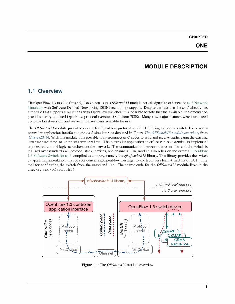
The OFSwitch13 module provides support for OpenFlow protocol version 1.3, bringing both a switch device and acontroller application interface to the ns-3 simulator, as depicted in Figure The OFSwitch13 module overview, from[Chaves2016]. With this module, it is possible to interconnect ns-3 nodes to send and receive traffic using the existingCsmaNetDevice or VirtualNetDevice. The controller application interface can be extended to implementany desired control logic to orchestrate the network. The communication between the controller and the switch isrealized over standard ns-3 protocol stack, devices, and channels. The module also relies on the external OpenFlow1.3 Software Switch for ns-3 compiled as a library, namely the ofsoftswitch13 library. This library provides the switchdatapath implementation, the code for converting OpenFlow messages to and from wire format, and the dpctl utilitytool for configuring the switch from the command line. The source code for the OFSwitch13 module lives in thedirectory src/ofswitch13.
ofsoftswitch13 library
ns-3 environment
external environment
OpenFlow 1.3 controller application interface
Protocolstack
NetDevice
Controller
(ns-3
no
de
)
OpenFlow 1.3 switch device
Protocolstack
NetDevice
Switch
(ns-3
no
de
)
CSMANetDeviceCSMA
NetDeviceCSMANetDevice
Channel
Co
ntr
ol p
lan
e
Da
ta p
lan
e
Figure 1.1: The OFSwitch13 module overview
1
OpenFlow 1.3 Module Documentation, Release 3.2.1
1.2 Design
1.2.1 OpenFlow 1.3 Switch Device
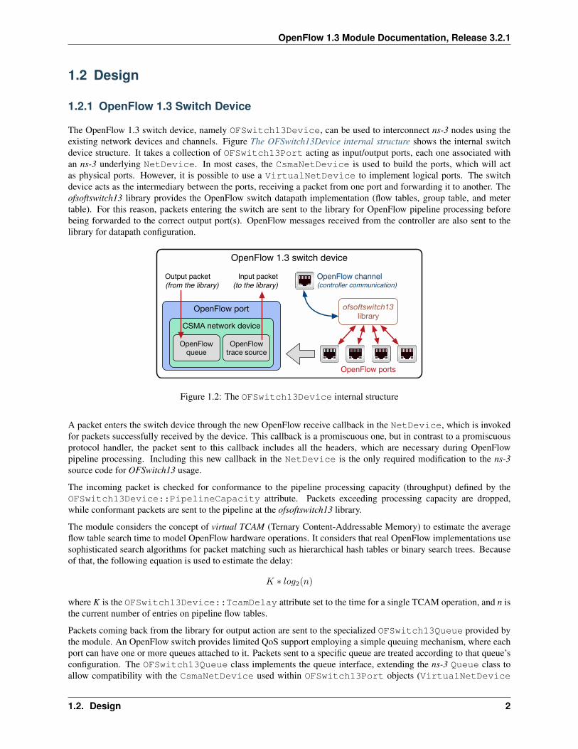
The OpenFlow 1.3 switch device, namely OFSwitch13Device, can be used to interconnect ns-3 nodes using theexisting network devices and channels. Figure The OFSwitch13Device internal structure shows the internal switchdevice structure. It takes a collection of OFSwitch13Port acting as input/output ports, each one associated withan ns-3 underlying NetDevice. In most cases, the CsmaNetDevice is used to build the ports, which will actas physical ports. However, it is possible to use a VirtualNetDevice to implement logical ports. The switchdevice acts as the intermediary between the ports, receiving a packet from one port and forwarding it to another. Theofsoftswitch13 library provides the OpenFlow switch datapath implementation (flow tables, group table, and metertable). For this reason, packets entering the switch are sent to the library for OpenFlow pipeline processing beforebeing forwarded to the correct output port(s). OpenFlow messages received from the controller are also sent to thelibrary for datapath configuration.
OpenFlow 1.3 switch device
OpenFlow ports
OpenFlow channel(controller communication)
OpenFlow port
Output packet
(from the library)
Input packet
(to the library)
CSMA network device
OpenFlow queue
OpenFlow trace source
ofsoftswitch13 library
Figure 1.2: The OFSwitch13Device internal structure
A packet enters the switch device through the new OpenFlow receive callback in the NetDevice, which is invokedfor packets successfully received by the device. This callback is a promiscuous one, but in contrast to a promiscuousprotocol handler, the packet sent to this callback includes all the headers, which are necessary during OpenFlowpipeline processing. Including this new callback in the NetDevice is the only required modification to the ns-3source code for OFSwitch13 usage.
The incoming packet is checked for conformance to the pipeline processing capacity (throughput) defined by theOFSwitch13Device::PipelineCapacity attribute. Packets exceeding processing capacity are dropped,while conformant packets are sent to the pipeline at the ofsoftswitch13 library.
The module considers the concept of virtual TCAM (Ternary Content-Addressable Memory) to estimate the averageflow table search time to model OpenFlow hardware operations. It considers that real OpenFlow implementations usesophisticated search algorithms for packet matching such as hierarchical hash tables or binary search trees. Becauseof that, the following equation is used to estimate the delay:
𝐾 * 𝑙𝑜𝑔2(𝑛)
where K is the OFSwitch13Device::TcamDelay attribute set to the time for a single TCAM operation, and n isthe current number of entries on pipeline flow tables.
Packets coming back from the library for output action are sent to the specialized OFSwitch13Queue provided bythe module. An OpenFlow switch provides limited QoS support employing a simple queuing mechanism, where eachport can have one or more queues attached to it. Packets sent to a specific queue are treated according to that queue’sconfiguration. The OFSwitch13Queue class implements the queue interface, extending the ns-3 Queue class toallow compatibility with the CsmaNetDevice used within OFSwitch13Port objects (VirtualNetDevice
1.2. Design 2
OpenFlow 1.3 Module Documentation, Release 3.2.1
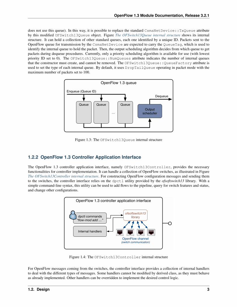
does not use this queue). In this way, it is possible to replace the standard CsmaNetDevice::TxQueue attributeby this modified OFSwitch13Queue object. Figure The OFSwitch13Queue internal structure shows its internalstructure. It can hold a collection of other standard queues, each one identified by a unique ID. Packets sent to theOpenFlow queue for transmission by the CsmaNetDevice are expected to carry the QueueTag, which is used toidentify the internal queue to hold the packet. Then, the output scheduling algorithm decides from which queue to getpackets during dequeue procedures. Currently, only a priority scheduling algorithm is available for use (with lowestpriority ID set to 0). The OFSwitch13Queue::NumQueues attribute indicates the number of internal queuesthat the constructor must create, and cannot be removed. The OFSwitch13Queue::QueueFactory attribute isused to set the type of each internal queue. By default, it uses DropTailQueue operating in packet mode with themaximum number of packets set to 100.
OpenFlow 1.3 queue
Enqueue (Queue ID)
Dequeue
…
Queue QueueQueue
Output
scheduller
Figure 1.3: The OFSwitch13Queue internal structure
1.2.2 OpenFlow 1.3 Controller Application Interface
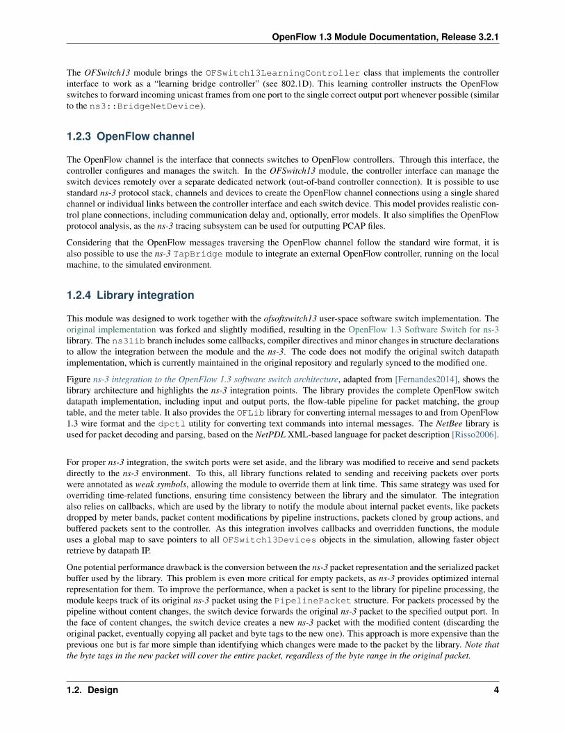
The OpenFlow 1.3 controller application interface, namely OFSwitch13Controller, provides the necessaryfunctionalities for controller implementation. It can handle a collection of OpenFlow switches, as illustrated in FigureThe OFSwitch13Controller internal structure. For constructing OpenFlow configuration messages and sending themto the switches, the controller interface relies on the dpctl utility provided by the ofsoftswitch13 library. With asimple command-line syntax, this utility can be used to add flows to the pipeline, query for switch features and status,and change other configurations.
OpenFlow 1.3 controller application interface
OpenFlow channel(switch communication)
ofsoftswitch13
library
Internal handlers
dpctl commands
“flow-mod add …”
Figure 1.4: The OFSwitch13Controller internal structure
For OpenFlow messages coming from the switches, the controller interface provides a collection of internal handlersto deal with the different types of messages. Some handlers cannot be modified by derived class, as they must behaveas already implemented. Other handlers can be overridden to implement the desired control logic.
1.2. Design 3
OpenFlow 1.3 Module Documentation, Release 3.2.1
The OFSwitch13 module brings the OFSwitch13LearningController class that implements the controllerinterface to work as a “learning bridge controller” (see 802.1D). This learning controller instructs the OpenFlowswitches to forward incoming unicast frames from one port to the single correct output port whenever possible (similarto the ns3::BridgeNetDevice).
1.2.3 OpenFlow channel
The OpenFlow channel is the interface that connects switches to OpenFlow controllers. Through this interface, thecontroller configures and manages the switch. In the OFSwitch13 module, the controller interface can manage theswitch devices remotely over a separate dedicated network (out-of-band controller connection). It is possible to usestandard ns-3 protocol stack, channels and devices to create the OpenFlow channel connections using a single sharedchannel or individual links between the controller interface and each switch device. This model provides realistic con-trol plane connections, including communication delay and, optionally, error models. It also simplifies the OpenFlowprotocol analysis, as the ns-3 tracing subsystem can be used for outputting PCAP files.
Considering that the OpenFlow messages traversing the OpenFlow channel follow the standard wire format, it isalso possible to use the ns-3 TapBridge module to integrate an external OpenFlow controller, running on the localmachine, to the simulated environment.
1.2.4 Library integration
This module was designed to work together with the ofsoftswitch13 user-space software switch implementation. Theoriginal implementation was forked and slightly modified, resulting in the OpenFlow 1.3 Software Switch for ns-3library. The ns3lib branch includes some callbacks, compiler directives and minor changes in structure declarationsto allow the integration between the module and the ns-3. The code does not modify the original switch datapathimplementation, which is currently maintained in the original repository and regularly synced to the modified one.
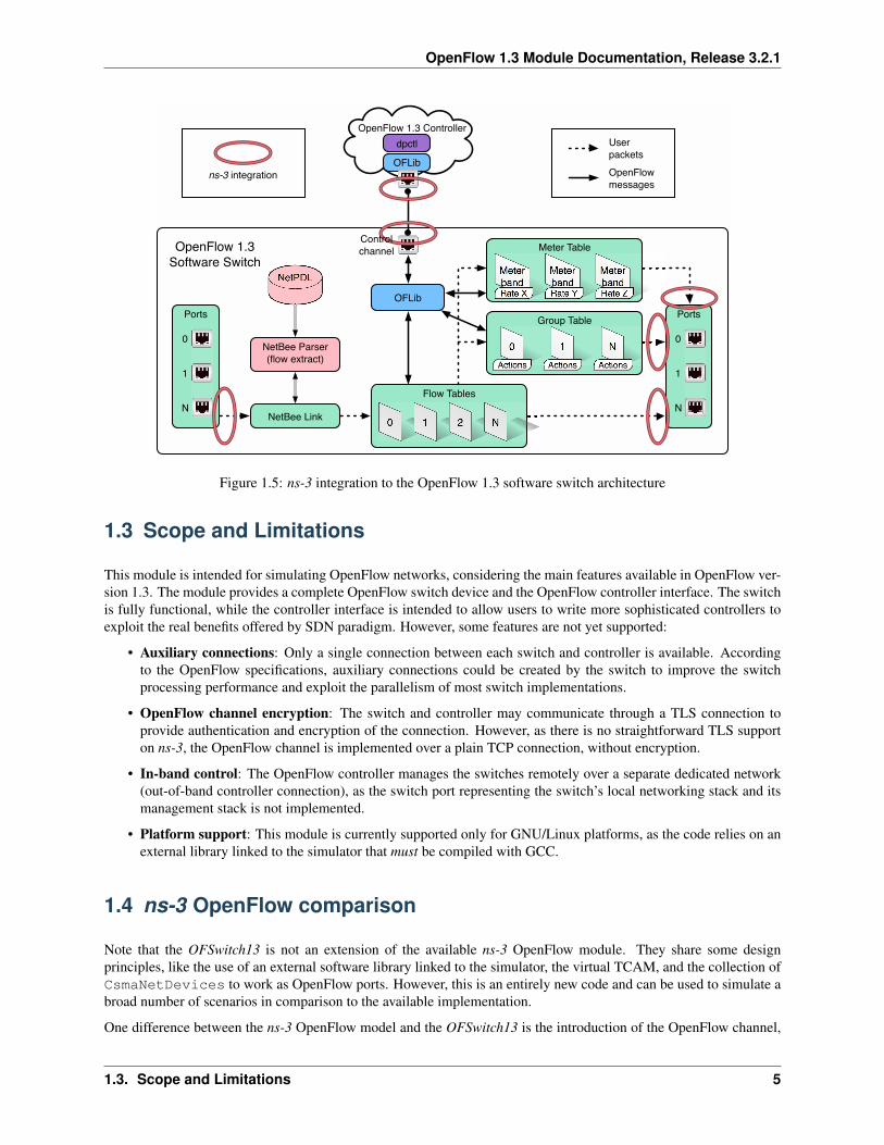
Figure ns-3 integration to the OpenFlow 1.3 software switch architecture, adapted from [Fernandes2014], shows thelibrary architecture and highlights the ns-3 integration points. The library provides the complete OpenFlow switchdatapath implementation, including input and output ports, the flow-table pipeline for packet matching, the grouptable, and the meter table. It also provides the OFLib library for converting internal messages to and from OpenFlow1.3 wire format and the dpctl utility for converting text commands into internal messages. The NetBee library isused for packet decoding and parsing, based on the NetPDL XML-based language for packet description [Risso2006].
For proper ns-3 integration, the switch ports were set aside, and the library was modified to receive and send packetsdirectly to the ns-3 environment. To this, all library functions related to sending and receiving packets over portswere annotated as weak symbols, allowing the module to override them at link time. This same strategy was used foroverriding time-related functions, ensuring time consistency between the library and the simulator. The integrationalso relies on callbacks, which are used by the library to notify the module about internal packet events, like packetsdropped by meter bands, packet content modifications by pipeline instructions, packets cloned by group actions, andbuffered packets sent to the controller. As this integration involves callbacks and overridden functions, the moduleuses a global map to save pointers to all OFSwitch13Devices objects in the simulation, allowing faster objectretrieve by datapath IP.
One potential performance drawback is the conversion between the ns-3 packet representation and the serialized packetbuffer used by the library. This problem is even more critical for empty packets, as ns-3 provides optimized internalrepresentation for them. To improve the performance, when a packet is sent to the library for pipeline processing, themodule keeps track of its original ns-3 packet using the PipelinePacket structure. For packets processed by thepipeline without content changes, the switch device forwards the original ns-3 packet to the specified output port. Inthe face of content changes, the switch device creates a new ns-3 packet with the modified content (discarding theoriginal packet, eventually copying all packet and byte tags to the new one). This approach is more expensive than theprevious one but is far more simple than identifying which changes were made to the packet by the library. Note thatthe byte tags in the new packet will cover the entire packet, regardless of the byte range in the original packet.
1.2. Design 4
OpenFlow 1.3 Module Documentation, Release 3.2.1
OFLib
Ports
0
1
N
OpenFlow 1.3 Controller
Ports
0
1
N
Flow Tables
0 1 2 N
NetBee Parser
(flow extract)
NetPDL
Meter Table
Meter
bandRate X
Meter
bandRate Y
Meter
bandRate Z
Group Table
0
Actions
1
Actions
N
Actions
OFLib
NetBee Link
dpctl
OpenFlow 1.3
Software Switch
OpenFlow
messages
User
packets
ns-3 integration
Control
channel
Figure 1.5: ns-3 integration to the OpenFlow 1.3 software switch architecture
1.3 Scope and Limitations
This module is intended for simulating OpenFlow networks, considering the main features available in OpenFlow ver-sion 1.3. The module provides a complete OpenFlow switch device and the OpenFlow controller interface. The switchis fully functional, while the controller interface is intended to allow users to write more sophisticated controllers toexploit the real benefits offered by SDN paradigm. However, some features are not yet supported:
• Auxiliary connections: Only a single connection between each switch and controller is available. Accordingto the OpenFlow specifications, auxiliary connections could be created by the switch to improve the switchprocessing performance and exploit the parallelism of most switch implementations.
• OpenFlow channel encryption: The switch and controller may communicate through a TLS connection toprovide authentication and encryption of the connection. However, as there is no straightforward TLS supporton ns-3, the OpenFlow channel is implemented over a plain TCP connection, without encryption.
• In-band control: The OpenFlow controller manages the switches remotely over a separate dedicated network(out-of-band controller connection), as the switch port representing the switch’s local networking stack and itsmanagement stack is not implemented.
• Platform support: This module is currently supported only for GNU/Linux platforms, as the code relies on anexternal library linked to the simulator that must be compiled with GCC.
1.4 ns-3 OpenFlow comparison
Note that the OFSwitch13 is not an extension of the available ns-3 OpenFlow module. They share some designprinciples, like the use of an external software library linked to the simulator, the virtual TCAM, and the collection ofCsmaNetDevices to work as OpenFlow ports. However, this is an entirely new code and can be used to simulate abroad number of scenarios in comparison to the available implementation.
One difference between the ns-3 OpenFlow model and the OFSwitch13 is the introduction of the OpenFlow channel,
1.3. Scope and Limitations 5
OpenFlow 1.3 Module Documentation, Release 3.2.1
using ns-3 devices and channels to provide the control connection between the controller and the switches. It allowsthe user to collect PCAP traces for this control channel, simplifying the analysis of OpenFlow messages. It is alsopossible the use of the ns-3 TapBridge module to integrate a local external OpenFlow 1.3 controller to the simulatedenvironment.
In respect to the controller, this module provides a more flexible interface. Instead of dealing with the internal librarystructures, the user can use simplified dpctl commands to build OpenFlow messages and send them to the switches.However, for processing OpenFlow messages received by the controller, the user still need to understand internallibrary structures and functions to extract the desired information.
In respect to the OpenFlow protocol implementation, the OFSwitch13 module brings many improved features fromversion 1.3 in comparison to the available ns-3 model (version 0.8.9). Some of the most important features are:
• Multiple tables: Prior versions of the OpenFlow specification did expose to the controller the abstraction ofa single table. OpenFlow 1.1 introduces a more flexible pipeline with multiple tables. Packets are processedthrough the pipeline, they are matched and processed in the first table, and may be matched and processed inother subsequent tables.
• Groups: The new group abstraction enables OpenFlow to represent a set of ports as a single entity for forward-ing packets. Different types of groups are provided to represent different abstractions such as multicasting ormultipathing. Each group is composed of a set group buckets, and each group bucket contains the set of actionsto be applied before forwarding to the port. Groups buckets can also forward to other groups.
• Logical ports: Prior versions of the OpenFlow specification assumed that all the ports of the OpenFlow switchwere physical ports. This version of the specification adds support for logical ports, which can represent complexforwarding abstractions such as tunnels. In the OFSwitch13 module, logical ports are implemented with the helpof VirtualNetDevice withing the OFSwitch13Port, where the user can configure callbacks to handlepackets properly.
• Extensible match support: Prior versions of the OpenFlow specification used a static fixed length structureto specify ofp_match, which prevents flexible expression of matches and prevents inclusion of new matchfields. The ofp_match has been changed to a TLV structure, called OpenFlow Extensible Match (OXM),which dramatically increases flexibility.
• IPv6 support: Basic support for IPv6 match and header rewrite has been added, via the OXM match support.
• Per-flow meters: Per-flow meters can be attached to flow entries and can measure and control the rate of packets.One of the primary applications of per-flow meters is to rate limit packets sent to the controller.
For ns-3 OpenFlow users who want to port existing code to this new module, please, check the Porting ns-3 OpenFlowcode section for detailed instructions.
1.5 ns-3 code compatibility
The only required modification to the ns-3 source code for OFSwitch13 integration is the inclusion of the new Open-Flow receive callback in the CsmaNetDevice and VirtualNetDevice. The module brings the patch for in-cluding this receive callback into ns-3 source code, available under src/ofswitch13/utils directory. Note theexistence of an src patch for the receive callbacks inclusion, and an optional doc patch that can be used for includingthe OFSwitch13 when compiling Doxygen and Sphinx documentation.
The current OFSwitch13 stable version is 3.2.1. This version is compatible with ns-3 version 3.28, and will notcompile with different ns-3 versions. If you need to use another ns-3 release, you can check the OFSwitch13 RE-LEASE_NOTES file for previous OFSwitch13 releases and their ns-3 version compatibility, but keep in mind that oldreleases may have known bugs and an old API. It is strongly recommended to use the latest module version for betterresults.
1.5. ns-3 code compatibility 6
OpenFlow 1.3 Module Documentation, Release 3.2.1
1.6 References
1. The reference [Fernandes2014] (in Portuguese) describes the details on the ofsoftswitch13 software switch im-plementation.
2. The reference [Chaves2016] presents the OFSwitch13 module, including details about module design and im-plementation. A case study scenario is also used to illustrate some of the available OpenFlow 1.3 modulefeatures.
3. The reference [Chaves2015] is related to the integration between OpenFlow and LTE technologies. The ns-3simulator, enhanced with the OFSwitch13 module, is used as the performance evaluation tool. This is the firstpublished work including simulation results obtained with the OFSwitch13 module.
1.6. References 7
CHAPTER
TWO
USAGE
2.1 Building the Module
The OFSwitch13 module was designed to work together with the ofsoftswitch13 library, providing an interface forinterconnecting the ns-3 simulator to the library. To this end, the ofsoftswitch13 project must be compiled as a staticlibrary and get appropriately linked to the ns-3 simulator.
By now, the user must download and compile the library code manually. Follow the instructions below to compileand link the ns-3 simulator to the ofsoftswitch13 library. These instructions were tested on Ubuntu 16.04 LTS. Otherdistributions or versions may require different steps, especially regarding library compilation.
2.1.1 Compiling the library
Before starting, ensure you have the following packages installed on your system:
$ sudo apt-get install build-essential gcc g++ python git mercurial unzip cmake$ sudo apt-get install libpcap-dev libxerces-c-dev libpcre3-dev flex bison$ sudo apt-get install pkg-config autoconf libtool libboost-dev
We need to compile the ofsoftswitch13 as a static library. The ofsoftswitch13 relies on another library, called NetBee(https://github.com/netgroup-polito/netbee), which is used to parse the network packets. So we need to compile andinstall them in the proper order.
Clone the NetBee repository and compile the library:
$ git clone https://github.com/netgroup-polito/netbee.git$ cd netbee/src/$ cmake .$ make
Add the shared libraries built to your library directory, configure dynamic linker run-time bindings, and copy theinclude files:
$ sudo cp ../bin/libn*.so /usr/local/lib$ sudo ldconfig$ sudo cp -R ../include/* /usr/include/
We are done with the NetBee library. Now, let’s proceed with the ofsoftswitch13 code. Clone the repository and updateto proper (preferably latest) release tag at the ns3lib branch (here, we are using v3.2.x):
$ git clone https://github.com/ljerezchaves/ofsoftswitch13$ cd ofsoftswitch13$ git checkout v3.2.x
8
OpenFlow 1.3 Module Documentation, Release 3.2.1
Configure and build the library (don’t forget to add the --enable-ns3-lib during configuration process):
$ ./boot.sh$ ./configure --enable-ns3-lib$ make
Once everything gets compiled, the static library libns3ofswitch13.a file will be available under theofsoftswitch13/udatapath/ directory.
2.1.2 Linking the library to the simulator
It’s time to download a recent (preferably stable) ns-3 code into your machine (here, we are going to use the mercurialrepository for ns-3.28):
$ hg clone http://code.nsnam.org/ns-3.28$ cd ns-3.28
Before configuring and compiling the simulator, download the OFSwitch13 code from the module repository and placeit inside a new /src/ofswitch13 folder. Update the code to the latest stable version (here, we are using 3.2.1):
$ hg clone https://bitbucket.org/ljerezchaves/ofswitch13-module src/ofswitch13$ cd src/ofswitch13$ hg update 3.2.1$ cd ../../
Patch the ns-3 code with the appropriated patches available under the ofswitch13/utils directory (use thepatches for the correct ns-3 version):
$ patch -p1 < src/ofswitch13/utils/ofswitch13-src-3_28.patch$ patch -p1 < src/ofswitch13/utils/ofswitch13-doc-3_28.patch
The ofswitch13-src-3_28.patch creates the new OpenFlow receive callback at CsmaNetDevice andVirtualNetDevie, allowing OpenFlow switch to get raw packets from these devices. These are the only re-quired changes in the ns-3 code for OFSwitch13 integration. The ofswitch13-doc-3_28.patch is optional. Itinstructs the simulator to include the module in the ns-3 model library and source code API documentation, which canbe helpful to compile the documentation using Doxygen and Sphinx.
Now, you can configure the ns-3 including the --with-ofswitch13 option to show the simulator where it canfind the ofsoftswitch13 main directory:
$ ./waf configure --with-ofswitch13=path/to/ofsoftswitch13
Check for the enabled ns-3 OpenFlow 1.3 Integration feature at the end of the configuration process. Finally, compilethe simulator:
$ ./waf
That’s it! Enjoy your ns-3 fresh compilation with OpenFlow 1.3 capabilities.
2.2 Basic usage
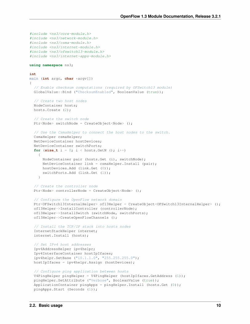
Here is the minimal script that is necessary to simulate an OpenFlow 1.3 network domain (code extracted fromofswitch13-first.cc example). This script connects two hosts to a single OpenFlow switch using CSMAlinks, and configure both the switch and the controller using the OFSwitch13InternalHelper class.
2.2. Basic usage 9
OpenFlow 1.3 Module Documentation, Release 3.2.1
#include <ns3/core-module.h>#include <ns3/network-module.h>#include <ns3/csma-module.h>#include <ns3/internet-module.h>#include <ns3/ofswitch13-module.h>#include <ns3/internet-apps-module.h>
using namespace ns3;
intmain (int argc, char *argv[]){
// Enable checksum computations (required by OFSwitch13 module)GlobalValue::Bind ("ChecksumEnabled", BooleanValue (true));
// Create two host nodesNodeContainer hosts;hosts.Create (2);
// Create the switch nodePtr<Node> switchNode = CreateObject<Node> ();
// Use the CsmaHelper to connect the host nodes to the switch.CsmaHelper csmaHelper;NetDeviceContainer hostDevices;NetDeviceContainer switchPorts;for (size_t i = 0; i < hosts.GetN (); i++){
NodeContainer pair (hosts.Get (i), switchNode);NetDeviceContainer link = csmaHelper.Install (pair);hostDevices.Add (link.Get (0));switchPorts.Add (link.Get (1));
}
// Create the controller nodePtr<Node> controllerNode = CreateObject<Node> ();
// Configure the OpenFlow network domainPtr<OFSwitch13InternalHelper> of13Helper = CreateObject<OFSwitch13InternalHelper> ();of13Helper->InstallController (controllerNode);of13Helper->InstallSwitch (switchNode, switchPorts);of13Helper->CreateOpenFlowChannels ();
// Install the TCP/IP stack into hosts nodesInternetStackHelper internet;internet.Install (hosts);
// Set IPv4 host addressesIpv4AddressHelper ipv4helpr;Ipv4InterfaceContainer hostIpIfaces;ipv4helpr.SetBase ("10.1.1.0", "255.255.255.0");hostIpIfaces = ipv4helpr.Assign (hostDevices);
// Configure ping application between hostsV4PingHelper pingHelper = V4PingHelper (hostIpIfaces.GetAddress (1));pingHelper.SetAttribute ("Verbose", BooleanValue (true));ApplicationContainer pingApps = pingHelper.Install (hosts.Get (0));pingApps.Start (Seconds (1));
2.2. Basic usage 10
OpenFlow 1.3 Module Documentation, Release 3.2.1
// Run the simulationSimulator::Stop (Seconds (10));Simulator::Run ();Simulator::Destroy ();
}
At first, don’t forget to enable checksum computations, which are required by the OFSwitch13 module. After creat-ing host and switch nodes, the user is responsible for connect the hosts and switches to create the desired networktopology. Using CSMA links for these connections is mandatory. Note that CsmaNetDevices created and installedinto switch node will be later configured as switch ports. After connecting hosts and switches, it’s time to create acontroller node and configure the OpenFlow network. The OFSwitch13InternalHelper can be used to con-figure an OpenFlow network domain with internal controller application. The InstallController() methodconfigures the controller node with a default OpenFlow learning controller application. The InstallSwitch()method installs the OpenFlow datapath into switch node and configures the switch ports. In the end, it’s mandatoryto call the CreateOpenFlowChannels() method to create the connections and start the communication betweenswitches and controllers.
The rest of this example follows the standard ns-3 usage: installing TCP/IP stack into host nodes, configuring IPaddresses, installing applications and running the simulation. Don’t install the TCP/IP stack into switches and con-trollers nodes (the helper does that for you). Also, don’t assign an IP address to devices configured as switch ports.For instructions on how to compile and run simulation programs, please refer to the ns-3 tutorial.
2.3 Helpers
2.3.1 OFSwitch13Helper
This module follows the pattern usage of standard helpers. The OFSwitch13Helper is a base class that must beextended to create and configure an OpenFlow 1.3 network domain, composed of one or more OpenFlow switchesconnected to single or multiple OpenFlow controllers. By default, the connections between switches and controllersare created using a single shared out-of-band CSMA channel, with IP addresses assigned to the 10.100.0.0/24 network.Users can modify this configuration by changing the OFSwitch13Helper::ChannelType attribute (dedicatedout-of-band connections over CSMA or point-to-point channels are also available), or setting a different IP networkaddress with the OFSwitch13Helper::SetAddressBase() static method. The use of standard ns-3 channelsand devices provides realistic connections with delay and error models.
This base class brings the methods for configuring the switches (derived classes configure the controllers). TheInstallSwitch() method can be used to create and aggregate an OFSwitch13Device object to each switchnode. By default, the InstallSwitch() method configures the switches without ports, so users must add the portsto the switch later, using the device AddSwitchPort(). However, it is possible to send to the InstallSwitch()method a container with NetDevices that will be configured as switch ports of a single switch node.
Each port is configured with the CsmaNetDevice created during the connection between switch nodes andother nodes in the simulation (the user must previously define these connections). It is also possible to use aVirtualNetDevice as a logical port, allowing the user to configure custom operations like tunneling.
After installing the switches and controllers, it is mandatory to use the CreateOpenFlowChannels() membermethod to effectively create and start the connections between all switches and all controllers on the same domain.After calling this method, you will not be allowed to install more switches nor controllers using this helper. Pleasenote that this helper was designed to configure a single OpenFlow network domain. If you want to configure separatedOpenFlow domains on your network topology (with their switches and controllers) so you may need to use a differenthelper instance for each domain.
This helper also allows users to enable some module outputs that are used for traffic monitoring and performanceevaluation. Please, check the Output section for detailed information.
2.3. Helpers 11
OpenFlow 1.3 Module Documentation, Release 3.2.1
2.3.2 OFSwitch13InternalHelper
This helper extends the base class and can be instantiated to create and configure an OpenFlow 1.3 network domaincomposed of one or more OpenFlow switches connected to a single or multiple internal simulated OpenFlow con-trollers. It brings methods for installing the controller and creating the OpenFlow channels.
To configure the controller, the InstallController() method can be used to create a (default) new learningcontroller application and install it into the controller node indicated as parameter. It is also possible to install a differ-ent controller application other than the learning controller using this same method by setting the proper applicationparameter. Note that this helper is prepared to install a single controller application at each controller node, so don’tinstall a second application on the same node, otherwise the helper will crash.
2.3.3 OFSwitch13ExternalHelper
This helper extends the base class and can be instantiated to create and configure an OpenFlow 1.3 network domaincomposed of one or more OpenFlow switches connected to a single external real OpenFlow controller. It bringsmethods for installing the controller node for TapBridge usage and creating the OpenFlow channels. The currentimplementation only supports the single shared CSMA channel type.
To configure the external controller, the InstallExternalController() method can be used to prepare thecontroller node so it can be used to connect internal simulated switches to an external OpenFlow controller running onthe local machine over a TapBridge device. It installs the TCP/IP stack into controller node, attach it to the commonCSMA channel, configure IP address for it and returns the NetDevice that the user will be responsible to bind to theTabBridge. Note that this helper is prepared to configure a single controller node. See the External controller sectionfor more details.
2.4 Attributes
2.4.1 OFSwitch13Controller
• Port: The port number on which the controller application listen for incoming packets. The default value isport 6653 (the official IANA port since 2013-07-18).
2.4.2 OFSwitch13Device
• DatapathId: The unique datapath identification of this OpenFlow switch. The datapath ID is a read-onlyattribute, automatically assigned by the object constructor.
• FlowTableSize: The maximum number of entries allowed on each flow table.
• GroupTableSize: The maximum number of entries allowed on group table.
• MeterTableSize: The maximum number of entries allowed on meter table.
• PipelineCapacity: The data rate used to model the pipeline processing capacity (throughput). Packetsexceeding the capacity are discarded.
• PortList: The list of ports available in this switch.
• TcamDelay: Average time to perform a TCAM operation in the pipeline. This value is used to calculate theaverage pipeline delay based on the number of flow entries in the tables, as described in OpenFlow 1.3 SwitchDevice.
• TimeoutInterval: The time between timeout operations in the pipeline. At each interval, the device checksif any flow in any table is timed out and update port status.
2.4. Attributes 12
OpenFlow 1.3 Module Documentation, Release 3.2.1
2.4.3 OFSwitch13Port
• PortQueue: The OpenFlow queue to use as the transmission queue in this port. When the port is constructedover a CsmaNetDevice, this queue is set for use in the underlying device. When the port is constructed overa VirtualNetDevice, this queue is not used.
2.4.4 OFSwitch13Queue
• QueueFactory: The object factory used when creating internal queues.
• QueueList: The list of internal queues associated with this port queue.
• NumQueues: The number of internal queues associated with this port queue.
2.4.5 OFSwitch13Helper
• ChannelDataRate: The data rate for the OpenFlow channel links.
• ChannelType: The configuration used to create the OpenFlow channel. Users can select between a singleshared CSMA connection, or dedicated connection between the controller and each switch, using CSMA orpoint-to-point links.
2.4.6 OFSwitch13ExternalHelper
• Port: The port number on which the external controller application listen for incoming packets. The defaultvalue is port 6653 (the official IANA port since 2013-07-18).
2.4.7 OFSwitch13StatsCalculator
• EwmaAlpha: The EWMA alpha parameter, which is the weight given to the most recent measured value whenupdating average metrics values.
• DumpTimeout: The interval between successive dump operations.
• OutputFilename: The filename used to save OpenFlow switch datapath performance statistics.
2.5 Output
This module relies on the ns-3 tracing subsystem for output. The OFSwitch13Helper base class allows usersto monitor control-plane traffic by enabling PCAP and ASCII trace files for the NetDevices used to createthe OpenFlow Channel(s). This approach can be useful to analyze the OpenFlow messages exchanged betweenswitches and controllers on this network domain. To enable these traces, use the EnableOpenFlowPcap() andEnableOpenFlowAscii() helper member functions after configuring the switches and creating the OpenFlowchannels. It is also possible to enable PCAP and ASCII trace files to monitor data-plane traffic on switch ports usingthe standard CsmaHelper trace functions.
For performance evaluation, the OFSwitch13StatsCalculator class can monitor statistics of an OpenFlowswitch datapath. The instances of this class connect to a collection of trace sources in the switch device and periodicallydumps the following datapath metrics on the output file:
1. Pipeline load regarding throughput (Kbits);
2. Pipeline load regarding packets;
2.5. Output 13
OpenFlow 1.3 Module Documentation, Release 3.2.1
3. Packets dropped while exceeding pipeline load capacity;
4. Packets dropped by meter bands;
5. Flow-mod operations executed by the switch;
6. Meter-mod operations executed by the switch;
7. Group-mod operations executed by the switch;
8. Packets-in sent from the switch to the controller;
9. Packets-out sent from the controller to the switch;
10. The average number of flow entries in pipeline tables;
11. The average number of meter entries in meter table;
12. The average number of group entries in group table;
13. Average switch buffer space usage (percent);
14. Average pipeline lookup delay for packet processing (microseconds).
To enable performance monitoring, use the EnableDatapathStats() helper member function after configuringthe switches and creating the OpenFlow channels. By default, statistics are dumped every second, but users canadjust this timeout by changing the OFSwitch13StatsCalculator::DumpTimeout attribute. Besides, forthe average metrics, an Exponentially Weighted Moving Average (EWMA) is used to update the values, and theattribute OFSwitch13StatsCalculator::EwmaAlpha can be adjusted to reflect the desired weight given tomost recent measured values.
When necessary, it is also possible to enable the internal ofsoftswitch13 library ASCII logging mechanism using twodifferent approaches:
1. The simplified OFSwitch13Helper::EnableDatapathLogs() static method dumps messages at de-bug level for all library internal modules into the output file (users can set the filename prefix);
2. The advanced ofs::EnableLibraryLog()method allow users to define the target log facility (the consoleor a file), set the filename, and also customize the logging levels for different library internal modules.
2.6 Porting ns-3 OpenFlow code
For ns-3 OpenFlow users that want to port existing code to the new OFSwitch13 module, keep in mind that this is not anextension of the available implementation. For simulation scenarios using the existing ns-3 OpenFlow module config-ured with the ns3::OpenFlowSwitchHelper helper and using the ns3::ofi::LearningController,it is possible to port the code to the OFSwitch13 module with little effort. The following code, based on theopenflow-switch.cc example, is used for demonstration:
#include "ns3/openflow-module.h"
// Connecting the terminals to the switchNode using CSMA devices and channels.// CsmaNetDevices created at the switchNode are in the switchDevices container.// ...
// Create the OpenFlow helperOpenFlowSwitchHelper ofHelper;
// Create the learning controller appPtr<ns3::ofi::LearningController> controller;controller = CreateObject<ns3::ofi::LearningController> ();if (!timeout.IsZero ())
2.6. Porting ns-3 OpenFlow code 14
OpenFlow 1.3 Module Documentation, Release 3.2.1
{controller->SetAttribute ("ExpirationTime", TimeValue (timeout));
}
// Install the switch device, ports and set the controllerofHelper.Install (switchNode, switchDevices, controller);
// Other configurations: TCP/IP stack, apps, monitors, etc.// ...
This code creates an ns3::ofi::LearningController object instance as the controller. It also sets the inter-nal attribute ExpirationTime for cache timeout. Then, the helper installs the OpenFlow switch device into theswitchNode node. The CSMA devices from switchDevices container are installed as OpenFlow ports, and thecontroller object is set as the OpenFlow controller for the network. The following code implements the samelogic in the OFSwitch13 module:
#include "ns3/ofswitch13-module.h"
// Connecting the terminals to the switchNode using CSMA devices and channels.// CsmaNetDevices created at the switchNode are in the switchDevices container.// ...
// Create the OpenFlow 1.3 helperPtr<OFSwitch13InternalHelper> of13Helper = CreateObject<OFSwitch13InternalHelper> ();
// Create the controller node and install the learning controller app into itPtr<Node> controllerNode = CreateObject<Node> ();of13Helper->InstallController (controllerNode);
// Install the switch device and ports.of13Helper->InstallSwitch (switchNode, switchDevices);
// Create the OpenFlow channel connections.of13Helper->CreateOpenFlowChannels ();
// Other configurations: TCP/IP stack, apps, monitors, etc.// ...
// Arbitrary simulation duration (can be changed for any value)Simulator::Stop (Seconds (10));
Note that the OFSwitch13 module requires a new node to install the controller application into it. TheInstallController() function creates the learning application object instance and installs it in thecontrollerNode. Then, the InstallSwitch() function installs the OpenFlow device into switchNodeand configures the CSMA devices from switchDevices container as OpenFlow ports. Finally, theCreateOpenFlowChannels() function configures the connection between the switch and the controller. Notethat the OFSwitch13LearningController does not provide the ExpirationTime attribute. Don’t forget toinclude the Simulator::Stop() command to schedule the time delay until the Simulator should stop; otherwise,the simulation will never end.
For users who have implemented new controllers in the ns-3 OpenFlow module, extending thens3::ofi::Controller class, are encouraged to explore the examples and the Doxygen documentationfor the OFSwitch13Controller base class. In a nutshell, the ReceiveFromSwitch() function is replacedby the internal handlers, used to process each type of OpenFlow message received from the switch. See the Extendingthe controller section for more details.
2.6. Porting ns-3 OpenFlow code 15
OpenFlow 1.3 Module Documentation, Release 3.2.1
2.7 Advanced Usage
2.7.1 dpctl commands
For constructing OpenFlow messages and sending them to the switches, the controller relies on the dpctl utilityto simplify the process. The dpctl is a management utility that enables some control over the OpenFlow switch.With this tool, it is possible to add flows to the flow table, query for switch features and status, and change otherconfigurations. The DpctlExecute() function can be used by derived controllers to convert a variety of dpctlcommands into OpenFlow messages and send it to the target switch. There’s also the DpctlSchedule() variant,which can be used to schedule commands to be executed just after the handshake procedure between the controllerand the switch (this can be useful for scheduling commands during the topology creation, before the simulation start).
Check the utility documentation for details on how to create the commands. Note that the documentation is intendedfor terminal usage in Unix systems, which is a little different from the usage in the DpctlExecute() function. Forthis module, ignore the options and switch reference, and consider only the command and the arguments. You can findsome examples of this syntax at The QoS controller example source code.
2.7.2 Extending the controller
The OFSwitch13Controller base class provides the necessary interface for controller implementation. It usesthe dpctl commands for sending OpenFlow messages to the switches. The controller also uses OpenFlow mes-sage handlers to process different OpenFlow message received from the switches. Some handler methods cannot bemodified by derived class, as they must behave as already implemented. Other handlers can be overridden by de-rived controllers to proper parse packets sent from switch to controller and implement the desired control logic. Thecurrent implementation of these virtual handler methods does nothing: only free the received message and returns 0.Note that handlers must free received messages (msg) when everything is fine. For HandleMultipartReply()implementation, note that several types of multipart replies can be filtered.
In the OFSwitch13LearningController implementation, the HandlePacketIn() function is used to han-dle packet-in messages sent from switch to this controller. It looks for L2 switching information, updates the structuresand sends a packet-out back to the switch. The HandleFlowRemoved() is used to handle expired flow entries no-tified by the switch to this controller. It looks for L2 switching information and removes associated entry.
The QosController example includes a non-trivial controller implementation that is used to configure the networkdescribed in The QoS controller example section. Several dpctl commands are used to configure the switches basedon network topology and desired control logic, while the HandlePacketIn() is used to filter packets sent to thecontroller by the switch. Note that the ofsoftswitch13 function oxm_match_lookup() is used across the code to ex-tract match information from the message received by the controller. For ARP messages, HandleArpPacketIn()exemplifies how to create a new packet at the controller and send to the network over a packet-out message. Develop-ers are encouraged to study the library internal structures to understand better how the handlers are implemented andalso how to build an OpenFlow message manually.
2.7.3 External controller
Considering that the OpenFlow messages traversing the OpenFlow channel follow the standard wire format, it ispossible to use the ns-3 TapBridge module to integrate an external OpenFlow 1.3 controller, running on thelocal system, to the simulated environment. The experimental external-controller.cc example uses theOFSwitch13ExternalHelper to this end, as follows:
// ...// Configure the OpenFlow network domain using an external controllerPtr<OFSwitch13ExternalHelper> of13Helper = CreateObject<OFSwitch13ExternalHelper> ();Ptr<NetDevice> ctrlDev = of13Helper->InstallExternalController (controllerNode);
2.7. Advanced Usage 16
OpenFlow 1.3 Module Documentation, Release 3.2.1
of13Helper->InstallSwitch (switches.Get (0), switchPorts [0]);of13Helper->InstallSwitch (switches.Get (1), switchPorts [1]);of13Helper->CreateOpenFlowChannels ();
// TapBridge the controller device to local machine// The default configuration expects a controller on local port 6653TapBridgeHelper tapBridge;tapBridge.SetAttribute ("Mode", StringValue ("ConfigureLocal"));tapBridge.SetAttribute ("DeviceName", StringValue ("ctrl"));tapBridge.Install (controllerNode, ctrlDev);
// ...
The InstallExternalController() function configures the controller node as a “ghost node” on the simu-lator. This function returns the net device created at the controller node (ctrlDev), and the user is responsible forbinding it to the TapBridge device, so it appears as if it were replacing the TAP device in the Linux. The default con-figuration expects that the OpenFlow controller is running on the local machine at port 6653 (the helper automaticallysets the IP address). Users can modify the local port number setting the OFSwitch13ExternalHelper::Portattribute.
This example was tested with the Floodlight 1.2 controller (http://www.projectfloodlight.org) running on the local ma-chine. Consistent behavior was observed once sufficient time elapses (say 3 to 5 minutes) between any two executions.
2.8 Examples
The examples are located in src/ofswitch13/examples.
2.8.1 Examples summary
• ofswitch13-first: Two hosts connected to a single OpenFlow switch. The default learning controller applicationmanages the switch.
• ofswitch13-multiple-controllers: Two hosts connected to a single OpenFlow switch. The default learningcontroller application manages both switches.
• ofswitch13-multiple-domains: Two hosts connected to different OpenFlow switches. An independent defaultlearning controller application manages each switch.
• ofswitch13-single-domain: Two hosts connected to different OpenFlow switches. Both switches are managedby the default learning controller application.
• ofswitch13-external-controller: Two hosts connected to different OpenFlow switches. The same externalcontroller application manages both switches.
• ofswitch13-logical-port: Two hosts connected to different OpenFlow switches. The tunnel controller applica-tion manages both switches. The ports interconnecting the switches are configured as logical ports, allowingswitches to de/encapsulate IP traffic using the GTP/UDP/IP tunneling protocol.
• ofswitch13-qos-controller: It represents the internal network of an organization, where servers and client nodesare located far from each other. A specialized OpenFlow QoS controller manages the network, implementingsome QoS functionalities and exploiting OpenFlow 1.3 features. The QoS controller example section belowdetails this example.
2.8. Examples 17
OpenFlow 1.3 Module Documentation, Release 3.2.1
2.8.2 The QoS controller example
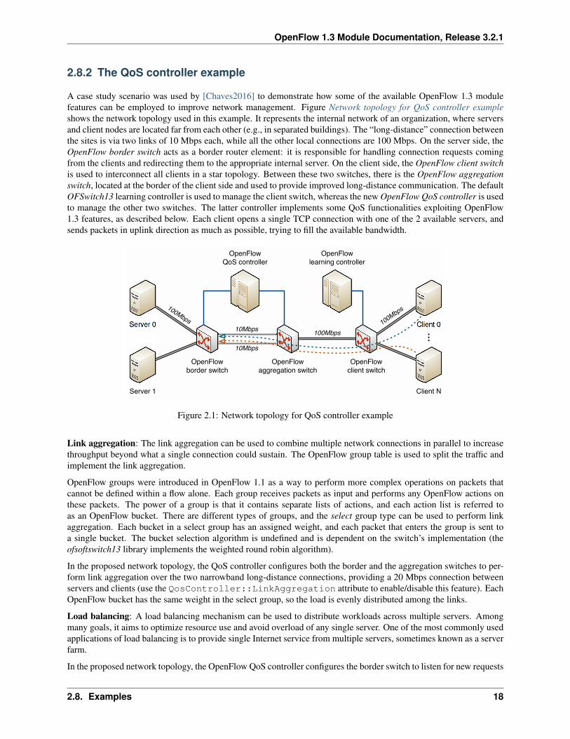
A case study scenario was used by [Chaves2016] to demonstrate how some of the available OpenFlow 1.3 modulefeatures can be employed to improve network management. Figure Network topology for QoS controller exampleshows the network topology used in this example. It represents the internal network of an organization, where serversand client nodes are located far from each other (e.g., in separated buildings). The “long-distance” connection betweenthe sites is via two links of 10 Mbps each, while all the other local connections are 100 Mbps. On the server side, theOpenFlow border switch acts as a border router element: it is responsible for handling connection requests comingfrom the clients and redirecting them to the appropriate internal server. On the client side, the OpenFlow client switchis used to interconnect all clients in a star topology. Between these two switches, there is the OpenFlow aggregationswitch, located at the border of the client side and used to provide improved long-distance communication. The defaultOFSwitch13 learning controller is used to manage the client switch, whereas the new OpenFlow QoS controller is usedto manage the other two switches. The latter controller implements some QoS functionalities exploiting OpenFlow1.3 features, as described below. Each client opens a single TCP connection with one of the 2 available servers, andsends packets in uplink direction as much as possible, trying to fill the available bandwidth.
Server 0
Server 1
OpenFlow
border switch
OpenFlow
aggregation switch
OpenFlow
client switch
OpenFlow
QoS controller
OpenFlow
learning controller
Client 0
Client N
…
100Mbps
100Mbps
10Mbps
100Mbps
10Mbps
Figure 2.1: Network topology for QoS controller example
Link aggregation: The link aggregation can be used to combine multiple network connections in parallel to increasethroughput beyond what a single connection could sustain. The OpenFlow group table is used to split the traffic andimplement the link aggregation.
OpenFlow groups were introduced in OpenFlow 1.1 as a way to perform more complex operations on packets thatcannot be defined within a flow alone. Each group receives packets as input and performs any OpenFlow actions onthese packets. The power of a group is that it contains separate lists of actions, and each action list is referred toas an OpenFlow bucket. There are different types of groups, and the select group type can be used to perform linkaggregation. Each bucket in a select group has an assigned weight, and each packet that enters the group is sent toa single bucket. The bucket selection algorithm is undefined and is dependent on the switch’s implementation (theofsoftswitch13 library implements the weighted round robin algorithm).
In the proposed network topology, the QoS controller configures both the border and the aggregation switches to per-form link aggregation over the two narrowband long-distance connections, providing a 20 Mbps connection betweenservers and clients (use the QosController::LinkAggregation attribute to enable/disable this feature). EachOpenFlow bucket has the same weight in the select group, so the load is evenly distributed among the links.
Load balancing: A load balancing mechanism can be used to distribute workloads across multiple servers. Amongmany goals, it aims to optimize resource use and avoid overload of any single server. One of the most commonly usedapplications of load balancing is to provide single Internet service from multiple servers, sometimes known as a serverfarm.
In the proposed network topology, the OpenFlow QoS controller configures the border switch to listen for new requests
2.8. Examples 18
OpenFlow 1.3 Module Documentation, Release 3.2.1
on the IP and port where external clients connect to access the servers. The switch forwards the new request to thecontroller, which decides which of the internal servers must take care of this connection. Then, it installs the matchrules into border switch to forward the subsequent packets from the same connection directly to the chosen server. Allthis happen without the client ever knowing about the internal separation of functions.
To implement this load balancing mechanism, the QoS controller depends on the extensible match support introducedin OpenFlow 1.2. Prior versions of the OpenFlow specification used a static fixed length structure to specify matches,which prevents flexible expression of matches and prevents the inclusion of new match fields. The extensible matchsupport allows the switch to match ARP request messages looking for the server IP address and redirect them to thecontroller, which creates the ARP reply message and send it back to the network. The set-field action is used by theborder switch to rewrite packet headers, replacing source/destinations IP addresses for packets leaving/entering theserver farm.
Per-flow meters: OpenFlow meter table, introduced in OpenFlow 1.3, enables the switch to implement various simpleQoS operations. A meter measures the rate of packets assigned to it and enables controlling the rate of those packets.The meter triggers a meter band if the packet rate or byte rate passing through the meter exceeds a predefined threshold.If the meter band drops the packet, it is called a rate limiter.
To illustrate the meter table usage, the OpenFlow QoS controller can optionally limit each connection throughput toa predefined data rate threshold, installing meter rules at the border switch along with the load balancing flow entries(use the QosController::EnableMeter and MeterRate attributes to enable/disable this feature).
2.9 Troubleshooting
• If your simulation go into an infinite loop, check for the required Simulator::Stop() command to schedulethe time delay until the Simulator should stop.
• Note that the OFSwitch13LearningController does not implement the Spanning Tree Protocol part of802.1D. Therefore, you have to be careful not to create loops on the connections between switches, otherwise,the network will collapse.
• For simulating scenarios with more than one OpenFlow network domain configured with theOFSwtich13InternalHelper, use a different helper instance for each domain.
• For using ASCII traces it is necessary to include the ns3::PacketMetadata::Enable () at the begin-ning of the program, before any packets being sent.
2.9. Troubleshooting 19

BIBLIOGRAPHY
[Fernandes2014] Eder. L. Fernandes, and Christian E. Rothenberg. “OpenFlow 1.3 Software Switch”. In: Salão deFerramentas do XXXII Simpósio Brasileiro de Redes de Computadores (SBRC), 2014.
[Risso2006] Fulvio Risso and Mario Baldi. “Netpdl: An extensible xml-based language for packet header descrip-tion”. Computer Networks, 50(5):688–706, 2006.
[Qi2010] Yaxuan Qi, Jeffrey Fong, Weirong Jiang, Bo Xu, Jun Li, and Viktor Prasanna. “Multi-dimensional PacketClassification on FPGA: 100 Gbps and Beyond”. In: IEEE International Conference on Field-ProgrammableTechnology (FPT), 2010.
[Chaves2016] Luciano J. Chaves, Islene C. Garcia, and Edmundo R. M. Madeira. “OFSwitch13: Enhancing ns-3 withOpenFlow 1.3 support”. In: 8th Workshop on ns-3 (WNS3), 2016.
[Chaves2015] Luciano J. Chaves, Vítor M. Eichemberger, Islene C. Garcia, and Edmundo R. M. Madeira. “IntegratingOpenFlow to LTE: some issues toward Software-Defined Mobile Networks”. In: 7th IFIP International Conferenceon New Technologies, Mobility and Security (NTMS), 2015.
20