Embed Size (px)
Citation preview
Additive Manufacturing (or 3D Printing)
Enhancing Interoperability Through Open Systems Architecture
DoD as a Model-Based Enterprise
Open SystemsOpen SystemsAdditive Manufacturing (or 3D Printing)
Enhancing Interoperability Through Open Systems Architecture
DoD as a Model-Based Enterprise
3
Contents October/December 2015
Gregory E. SaundersDirector, Defense Standardization Program Office
Tim KoczanskiEditor, Defense Standardization Program Journal
Defense Standardization Program Office8725 John J. Kingman Road, STOP 5100
Fort Belvoir, VA 22060-6220
703-767-6888Fax 703-767-6876
dsp.dla.mil
The Defense Standardization Program Jour-nal (ISSN 0897-0245) is published four times a year by the Defense Standardization Pro-gram Office (DSPO). Opinions represented here are those of the authors and may not represent official policy of the U.S. Depart-ment of Defense. Letters, articles, news items, photographs, and other submissions for the DSP Journal are welcomed and en-couraged. Send all materials to Editor, DSP Journal, Defense Standardization Program Office, 8725 John J. Kingman Road, STOP 5100, Fort Belvoir, VA 22060-6220. DSPO is not responsible for unsolicited materials. Materials can be submitted digitally by the following means:
e-mail to [email protected] CD or DVD to DSP Journal at the above
address.
DSPO reserves the right to modify or reject any submission as deemed appropriate.
9
15
1 Director’s Forum
3 Additive Manufacturing (or 3D Printing)
9 Enhancing Interoperability Through
Open Systems Architecture
17 DoD as a Model-Based Enterprise
Departments 24 Program News 26 Events 28 People
The DSP Journal is available only in electronic form.
To receive issues, please subscribe at the DSP website, www.dsp.dla.mil,
or e-mail [email protected] and put “Subscribe” in the subject line.
dsp.dla.mil 1
Director’s Forum
There has been a lot of emphasis recently in the Department of Defense on the use
of open systems architecture. Identified as a key tenet of better buying power, open
systems architecture can help promote effective competition because it enhances
system interoperability and the ability to integrate new capabilities without the re-
design of entire systems or large portions of the enterprise. In asking the question
“What makes an open system truly open?”, the answer—believe it or not—is with
consensus standards.
When we think of open systems architectures, it’s important to realize that there is a direct correlation between consensus standards and open systems architectures. Modular design is based primarily on widely supported—consensus-based—standards for their key interfaces. These key interfaces are an important element of making systems interoperable, so future modernization efforts can be made without having to scrap or completely redesign the legacy system. Because open system architectures employ widely accepted standards that have been validated by the market, these standard interfaces make integration and interoperability pos-sible. Not only can this save time with development, maintenance, and sustainment activities, but it also helps save precious program dollars.
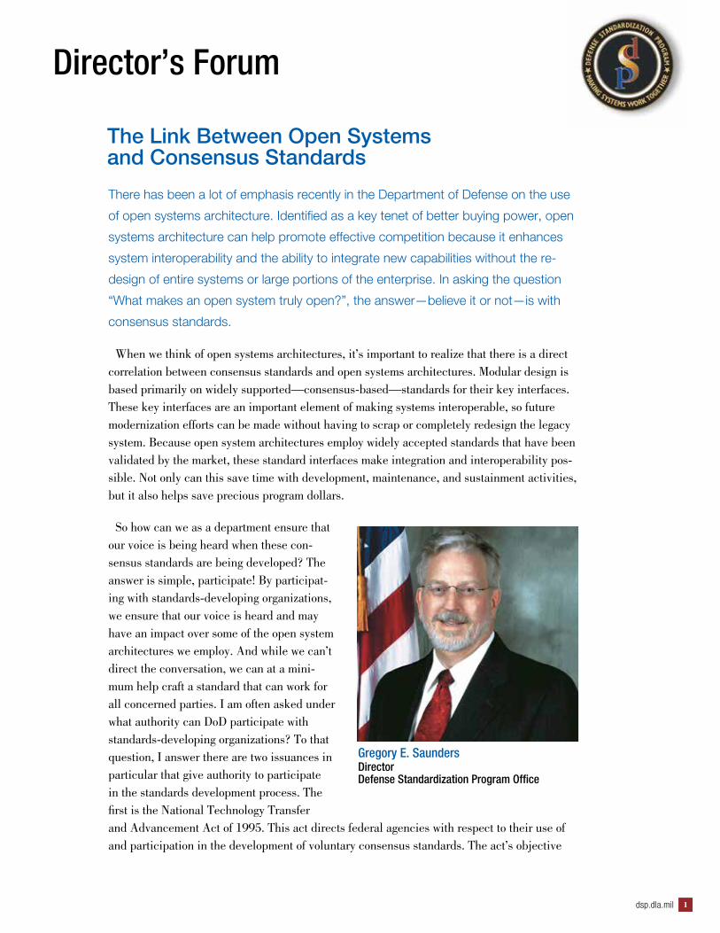
So how can we as a department ensure that our voice is being heard when these con-sensus standards are being developed? The answer is simple, participate! By participat-ing with standards-developing organizations, we ensure that our voice is heard and may have an impact over some of the open system architectures we employ. And while we can’t direct the conversation, we can at a mini-mum help craft a standard that can work for all concerned parties. I am often asked under what authority can DoD participate with standards-developing organizations? To that question, I answer there are two issuances in particular that give authority to participate in the standards development process. The first is the National Technology Transfer and Advancement Act of 1995. This act directs federal agencies with respect to their use of and participation in the development of voluntary consensus standards. The act’s objective
Gregory E. SaundersDirectorDefense Standardization Program Office
The Link Between Open Systems and Consensus Standards
DSP JOURNAL October-December 20152
is for federal agencies to adopt voluntary consensus standards, wherever possible, in lieu of creating government-unique standards. The other document—which provides more in-depth information in the mechanics of participating in the development of voluntary consensus stan-dards—is OMB Circular A-119, “Federal Participation in the Development and Use of Vol-untary Consensus Standards and in Conformity Assessment Activities.” The circular—which was just recently revised—not only gives those of us in government the authority to sit at the table, but also clarifies many of the roles and responsibilities we as government employees can play in the development process.
Given that the circular was just released, I would like to provide several highlights as to the content of some of the revisions. While the spirit of the circular didn’t change, more emphasis has been placed on providing clarity for those of us in government in how we participate. The circular provides additional guidance for agency participation in standards-development ac-tivities. The revised circular also strengthens the role of agency standards executives. While this was done to encourage better internal coordination and training on standards, this also helps to elevate the role of standardization within an agency. The circular provides guidance to agencies on how they should implement provisions of the circular in their rulemaking and guidance documents, as well as what factors to consider when incorporating standards by ref-erence in regulation. But the most important take-away from this revision is that the circular maintains the government’s strong preference for using voluntary consensus standards over government-unique standards in federal regulation and procurement.
All that said, this issue of the Defense Standardization Program Journal focuses on the development and use of open systems. As you read through these articles, keep a keen eye on how the application of open systems architectures and consensus standards align. Perhaps you will be able to draw conclusions through your own experience of where the use of open system architectures may affect your program or what voluntary consensus standards can be used in lieu of government-unique standards. For more information on OMB Circular A-119, please go to https://www.whitehouse.gov/sites/default/files/omb/inforeg/revised_circular_a-119_as_of_1_22.pdf.

dsp.dla.mil 3
By Denise Duncan
Additive Manufacturing (or 3D Printing)
dsp.dla.mil 3
DSP JOURNAL October-December 20154
DDoD’s weapon and other systems keep soldiers, sailors, and airmen safe and effective
in the field; and it takes over a billion parts per year to keep those systems running.
When a new technology or process affects the logistics of providing those parts where
and when needed, DoD pays attention; and so it is with the manufacturing process of
additive manufacturing (AM), sometimes called “3D printing.” AM has the potential to
be a transformative technology, completely changing the way we think about designing,
manufacturing, and delivering parts and goods. In 2012 The Economist called additive
manufacturing “a third industrial revolution,”1 and since then it has published eight
additional articles on its growth in manufacturing. AM has achieved a foothold in the
defense industrial base and will grow in use for certain types of parts.
Additive manufacturing is the process of building an object by depositing layers of ma-
terial, one layer at a time. Contrast that approach with our current “subtractive” pro-
cesses where we cut away or subtract (by milling, grinding, drilling, etc.) material from
a block of metal or other material. To imagine one AM approach, picture a laser printer
that, instead of ink cartridges, has cartridges filled with very fine powdered metal or plas-
tic. A 0.1-millimeter-thick layer of powder is laid down, and a laser sinters the powder
only in those places where a cross-section of the final object will be solid. The build plat-
form drops a tenth of a millimeter, and the process is repeated. Videos of AM abound on
the Internet, and viewing one or two of those will make the process more intuitive for the
reader.2
Characterizing AM by Processes Used
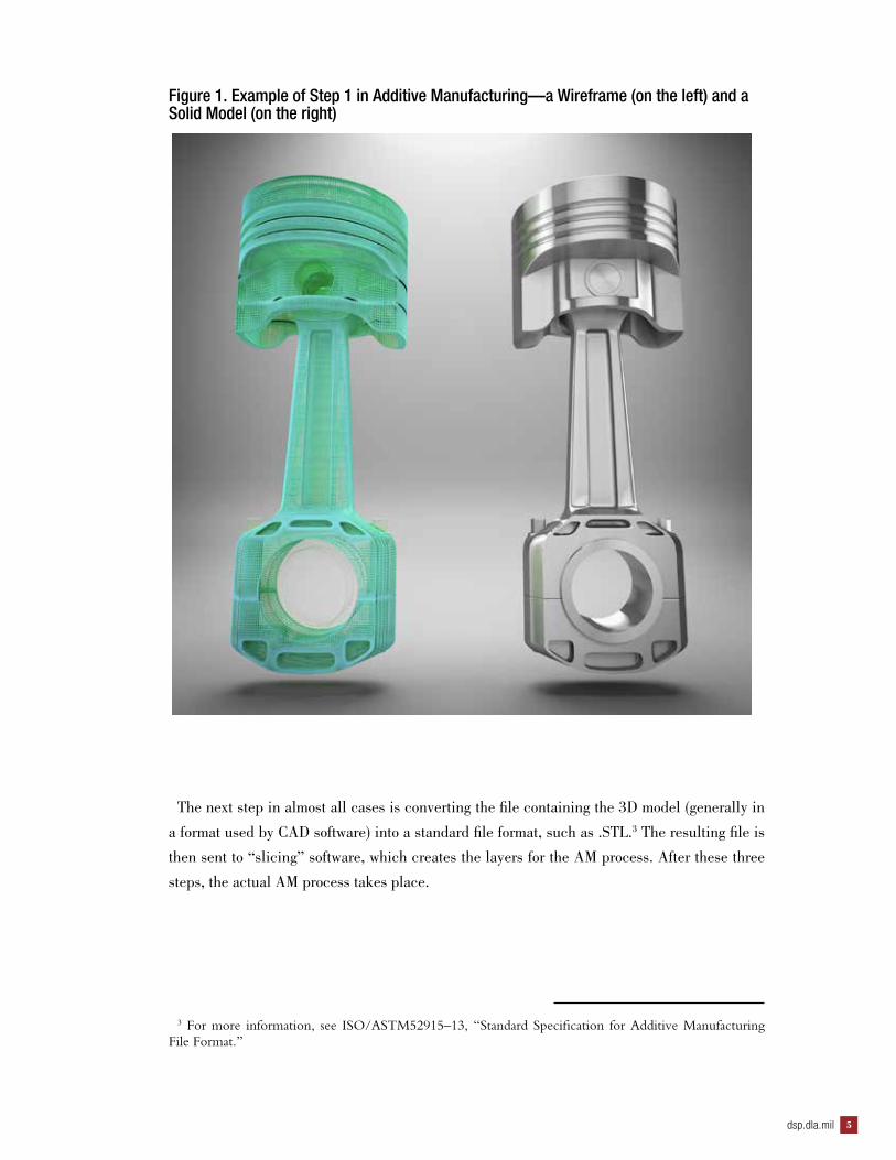
In general, the AM process starts with a three-dimensional (3D) model of the object
to be built. This is usually created by computer-aided design (CAD) software, or from a
3D scan of an existing object. 3D scans can be especially useful in the case of repair or
rebuild tasks, because the scan will capture changes to the article due to use—which is
useful feedback for designers of the article. Examples of both a wireframe and a solid
model are shown in Figure 1.
1 The Economist, April 21, 2012, http://www.economist.com/node/21553017.
2 http://www.ted.com/talks/lang/en/lisa_harouni_a_primer_on_3d_printing.html.
dsp.dla.mil 5
Figure 1. Example of Step 1 in Additive Manufacturing—a Wireframe (on the left) and a Solid Model (on the right)
The next step in almost all cases is converting the file containing the 3D model (generally in
a format used by CAD software) into a standard file format, such as .STL.3 The resulting file is
then sent to “slicing” software, which creates the layers for the AM process. After these three
steps, the actual AM process takes place.
3 For more information, see ISO/ASTM52915–13, “Standard Specification for Additive Manufacturing File Format.”
DSP JOURNAL October-December 20156
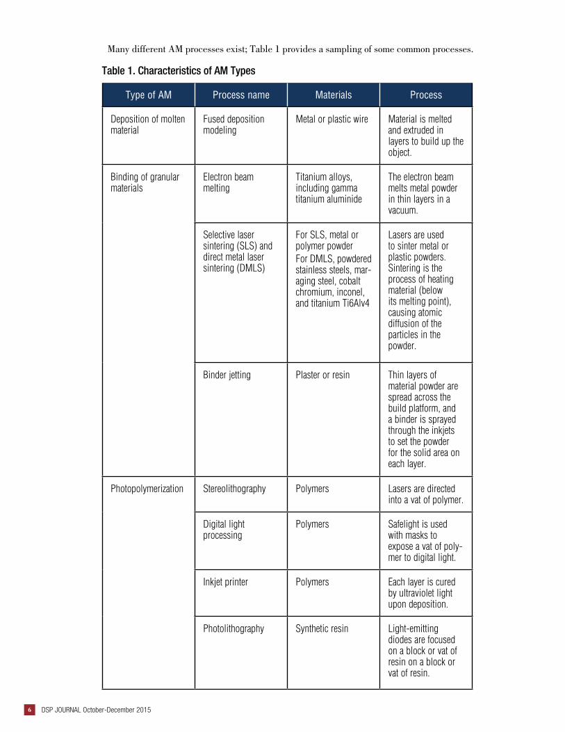
Many different AM processes exist; Table 1 provides a sampling of some common processes.
Table 1. Characteristics of AM Types
Type of AM Process name Materials Process
Deposition of molten material
Fused deposition modeling
Metal or plastic wire Material is melted and extruded in layers to build up the object.
Binding of granular materials
Electron beam melting
Titanium alloys, including gamma titanium aluminide
The electron beam melts metal powder in thin layers in a vacuum.
Selective laser sintering (SLS) and direct metal laser sintering (DMLS)
For SLS, metal or polymer powderFor DMLS, powdered stainless steels, mar-aging steel, cobalt chromium, inconel, and titanium Ti6Alv4
Lasers are used to sinter metal or plastic powders. Sintering is the process of heating material (below its melting point), causing atomic diffusion of the particles in the powder.
Binder jetting Plaster or resin Thin layers of material powder are spread across the build platform, and a binder is sprayed through the inkjets to set the powder for the solid area on each layer.
Photopolymerization Stereolithography Polymers Lasers are directed into a vat of polymer.
Digital light processing
Polymers Safelight is used with masks to expose a vat of poly-mer to digital light.
Inkjet printer Polymers Each layer is cured by ultraviolet light upon deposition.
Photolithography Synthetic resin Light-emitting diodes are focused on a block or vat of resin on a block or vat of resin.
dsp.dla.mil 7
Advantages of AMOne of the early uses of AM was for rapid prototyping. Studies have shown that the use
of 3D modeling software, combined with rapid prototyping, results in significant savings
of both time and money.4 Businesses that used both approaches typically got products to
market earlier and saved significantly on product development costs. When a business uses
AM to build prototypes, it can save 50 percent of the time normally required to produce the
prototype. Sending an article out for fabrication, it will typically take 2 to 3 weeks until the
prototype is in hand. When using in-house AM, the time can be cut to 2 to 3 days. Using
AM to build a wireframe physical model (versus a solid model of the prototype) can cut this
time even further.
Another advantage of AM is its flexibility, which gives businesses the ability to make
modifications to prototypes or customize products for different customers. Finally, the pro-
cesses employed in AM allow freedom of geometry, and that changes the rules of design.
The “design for manufacturability” step can be greatly simplified, and items can be pro-
duced with significantly fewer process steps. That, in turn, makes it possible to produce
highly complex geometries economically.
Labor savings also are significant, because once the design files are loaded to the AM
process, little labor is involved, except for a finishing process for some products. AM also
allows far more freedom in design. For example, GE Research invested $50 million in a 3D
printing facility in Auburn, Alabama, to produce fuel nozzles for the new LEAP jet engine.
To start, it will print 1,000 nozzles a year, but eventually the number may reach 40,000.
The fuel nozzle in a jet engine is a complex part that has to withstand high temperature and
pressure. Normally it is made from 20 different components. GE instead prints the part in
a single AM process, using a laser to fuse layers of a powdered alloy made up of cobalt,
chrome, and molybdenum. The resulting nozzle is 25 percent lighter and 5 times more du-
rable than the traditionally manufactured one.
Finally, AM has positive logistical impacts. By building items close to where they will
be used, much of the transportation of the finished object can be eliminated. For example,
the National Aeronautics and Space Administration (NASA) has tested 3D printing in ze-
ro-gravity flight; its aim is to develop AM for the International Space Station to reduce the
number of spare parts required to be transported to, and stored on, the station. NASA also
recently awarded three teams a total of $40,000 in the first stage of the 3-D Printed Habi-
tat Challenge Design Competition, to produce architectural concepts for a habitat on Mars
using AM and materials found on Mars.
4 Aberdeen Group, The Transition from 2D Drafting to 3D Modeling Benchmark Report, September 2006.
DSP JOURNAL October-December 20158
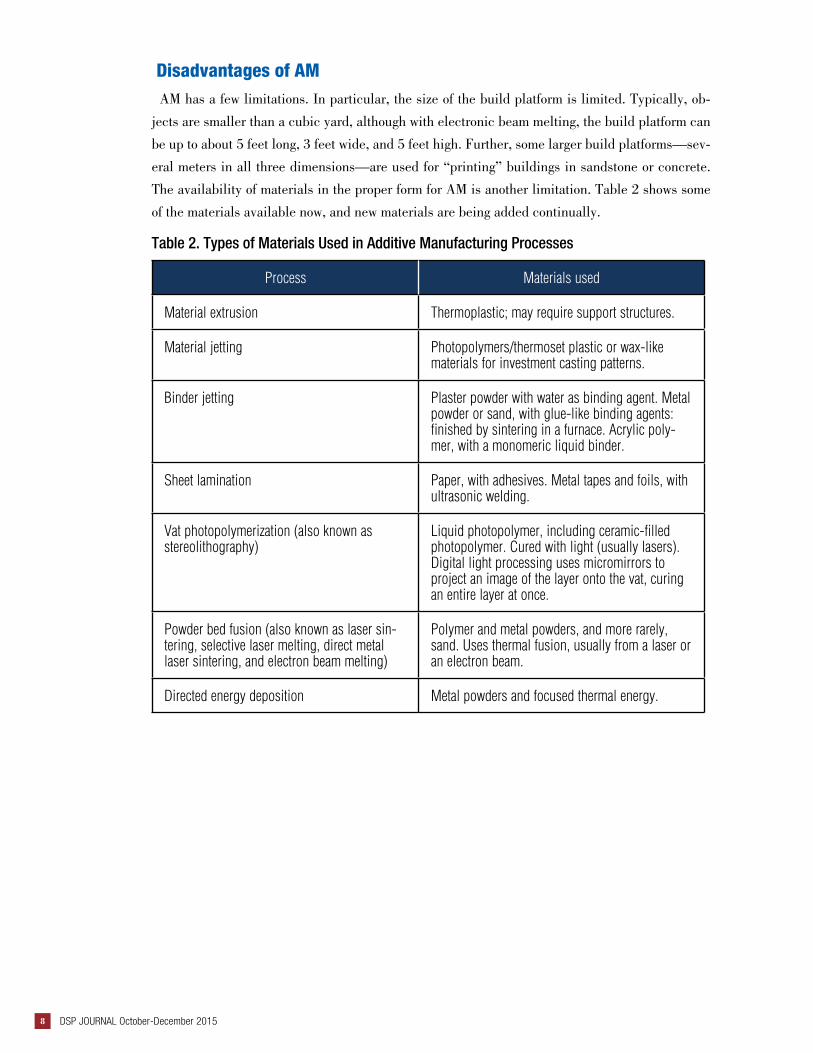
Disadvantages of AMAM has a few limitations. In particular, the size of the build platform is limited. Typically, ob-
jects are smaller than a cubic yard, although with electronic beam melting, the build platform can
be up to about 5 feet long, 3 feet wide, and 5 feet high. Further, some larger build platforms—sev-
eral meters in all three dimensions—are used for “printing” buildings in sandstone or concrete.
The availability of materials in the proper form for AM is another limitation. Table 2 shows some
of the materials available now, and new materials are being added continually.
Table 2. Types of Materials Used in Additive Manufacturing Processes
Process Materials used
Material extrusion Thermoplastic; may require support structures.
Material jetting Photopolymers/thermoset plastic or wax-like materials for investment casting patterns.
Binder jetting Plaster powder with water as binding agent. Metal powder or sand, with glue-like binding agents: finished by sintering in a furnace. Acrylic poly-mer, with a monomeric liquid binder.
Sheet lamination Paper, with adhesives. Metal tapes and foils, with ultrasonic welding.
Vat photopolymerization (also known as stereolithography)
Liquid photopolymer, including ceramic-filled photopolymer. Cured with light (usually lasers). Digital light processing uses micromirrors to project an image of the layer onto the vat, curing an entire layer at once.
Powder bed fusion (also known as laser sin-tering, selective laser melting, direct metal laser sintering, and electron beam melting)
Polymer and metal powders, and more rarely, sand. Uses thermal fusion, usually from a laser or an electron beam.
Directed energy deposition Metal powders and focused thermal energy.

dsp.dla.mil 9
Finally, AM is not the optimal process for high-volume manufacturing, unless some cus-
tomization is required. For example, AM is used to mass produce the clear plastic “align-
ers” used to straighten teeth. These are built from a model of a client’s teeth, and then
the model is changed very slightly over many iterations, to gradually align the teeth to the
desired “bite.” But typical assembly-line methods are more suited for mass-producing
products that are identical for every customer.
Current Applications of AM
Rapid prototyping is an example of AM integrated with traditional manufacturing pro-
cesses. Even when mass production is needed, AM can shorten cycle times for engineer-
ing reviews by providing a physical prototype in much less time than getting prototypes
developed by an outside firm. Reverse engineering is used to (for example) reproduce
items if the design documentation has been lost. When technology is used to create a 3D
model of the item (whether by laser scanning, x-ray, or magnetic resonance imaging), the
3D model can be used as input to the AM process.
Medical and dental device applications are plentiful, due to AM’s customization capa-
bilities. For example, AM is used to develop surgical guides, customized prostheses, and
engineered tissue scaffolds. In addition, AM is used in some applications to create geom-
etries not possible with traditional manufacturing techniques, resulting in new designs
with higher strength and lower weight. AM also supports manufacturing of electronic
items, by printing the electronics embedded into the final product.
DSP JOURNAL October-December 201510
About the Author
Denise Duncan is a senior fellow at LMI with more than 30 years of information systems management experience. She has managed a wide variety of projects, from assisting senior leaders with portfolio man-agement to strategic planning for chief information officers. For the past 12 years, Ms. Duncan has worked extensively on the application of data management principles to engineering and scientific data. She has authored standards, handbooks, and training materials in enterprise-level data management and informa-tion management. Ms. Duncan has been honored as a technical fellow of TechAmerica and is the vice pres-ident for programs in the local chapter of Data Management Association–International.
DoD Applications of AM
Additive manufacturing is already in use by DoD and its supply chain. Original equipment man-
ufacturers routinely use AM for rapid prototyping of new products, for molds and casting patterns,
and for direct part production. The Joint Strike Fighter contains many parts manufactured using
laser sintering and other AM techniques. DoD is using AM in medical applications as well, for ex-
ample, to plan surgeries and to visualize reconstructive surgery, surgical implants, and prosthetics.
The Army’s Rapid Equipping Force has deployed mobile laboratories to the war zone in Afghan-
istan. Each mobile lab—a roughly $2.5 million investment—is a 20-foot container and can be
transported by truck or helicopter to any location. These labs speed up the design and production
processes; the warfighter can provide feedback to the designer and, with rapid iterations, can pro-
ceed to a design for a complete solution. Engineers can work together inside each mobile lab to
create needed items or repair parts made of plastic, steel, and aluminum. If the end item is going
to be mass produced, the design can be transmitted back to the United States for procurement and
production.

dsp.dla.mil 11
By Joseph Norton
dsp.dla.mil 11
Enhancing Interoperability through Open Systems
Architecture
DSP JOURNAL October-December 201512
AA constantly changing technology landscape and expectations to adapt and innovate
quickly make it challenging to acquire, integrate, and upgrade fielded systems, espe-
cially in the current economic environment. Highly integrated systems are often propri-
etary and vendor locked, expensive, and difficult to upgrade with emerging technology. A
strategy for overcoming these challenges is to design highly interoperable systems. This
means enabling systems or components to exchange services and information through
seamless, end-to-end connectivity. This article describes how open systems architecture
(OSA) leverages reusable components, well-defined interfaces, and standard interface
specifications to enhance system interoperability. This article also discusses design prin-
ciples for implementing OSA to enhance interoperability.
Open Systems Architecture—An OverviewOSA is an integrated business and technical approach to acquire and assemble in-
teroperablecomponents using modular systems design. The business strategy is to drive
down costs, enable systems to easily adapt to changing business needs, and increase the
number of available vendors to create competition-driven product lines. The technical
approach decomposes systems into components that interact through key interfaces ac-
cording to formal specifications.
OSA aims to enhance interoperability by realizing the following benefits:
▌ Increased flexibility in vendor selection fostered by competitive marketplaces
▌ Interchangeable components to simplify maintenance, upgrades,
and technology insertion
▌ Greater accessibility to innovative technology
▌ Shortened design times and streamlined development processes
▌ Improved information sharing and data quality
▌ Reduced total cost of ownership.
OSA applies to all types of systems. Although some of its most familiar uses are in com-
puters, software, and electronics, this approach applies to other areas, such as communi-
cations, electricity production and use, and the design of weapons, vehicles, and artillery
for armed forces. Computer networks are tightly integrated systems that employ standard
hardware, such as cables, routers, and servers. This hardware uses standard protocol to
enable devices and machines to communicate and exchange information. With constantly
changing operational needs for new weapons and armor, the armed forces use a similar
approach to enhance interoperability in military vehicles. By developing standard elec-
tronic platforms and mounting systems, military vehicles can quickly access electronic
and information assets and introduce new weapon and sensor capabilities.
dsp.dla.mil 13
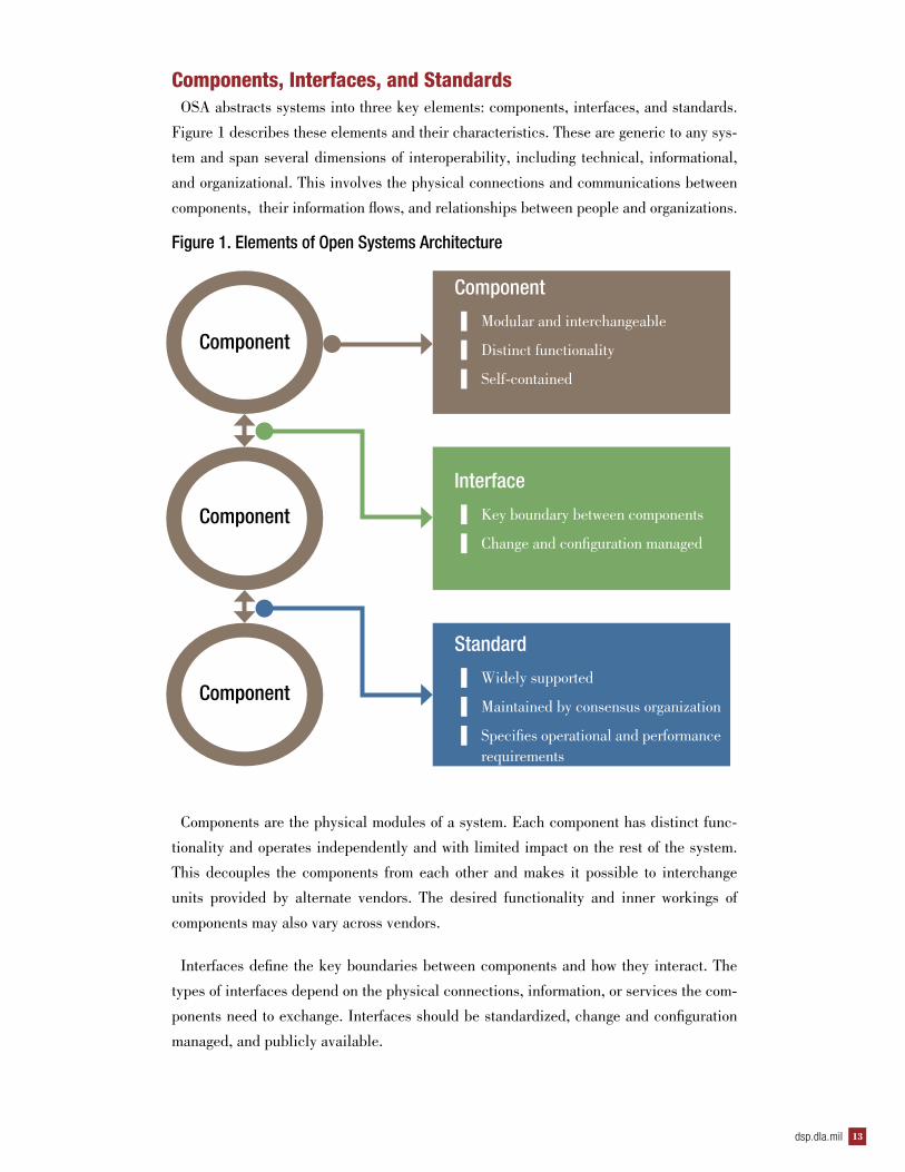
Components, Interfaces, and StandardsOSA abstracts systems into three key elements: components, interfaces, and standards.
Figure 1 describes these elements and their characteristics. These are generic to any sys-
tem and span several dimensions of interoperability, including technical, informational,
and organizational. This involves the physical connections and communications between
components, their information flows, and relationships between people and organizations.
Figure 1. Elements of Open Systems Architecture
Components are the physical modules of a system. Each component has distinct func-
tionality and operates independently and with limited impact on the rest of the system.
This decouples the components from each other and makes it possible to interchange
units provided by alternate vendors. The desired functionality and inner workings of
components may also vary across vendors.
Interfaces define the key boundaries between components and how they interact. The
types of interfaces depend on the physical connections, information, or services the com-
ponents need to exchange. Interfaces should be standardized, change and configuration
managed, and publicly available.
Component
Component
Component
Component
▌ Modular and interchangeable
▌ Distinct functionality
▌ Self-contained
Interface
▌ Key boundary between components
▌ Change and configuration managed
Standard
▌ Widely supported
▌ Maintained by consensus organization
▌ Specifies operational and performance requirements
DSP JOURNAL October-December 201514
Standards define the specifications for how components interact through defined inter-
faces. These include operational and performance requirements, such as security, reli-
ability, and maintainability, that describe how an interface should perform. Standards
should be managed by consensus groups and widely accepted to ensure they meet the
requirements across all systems.
Design Principles to Ensure InteroperabilityOSA considers interoperability through the entire life cycle of a system. A program must
design its systems to be interoperable from the time it acquires and defines its compo-
nents, interfaces, and standards through the time when those systems become operational
and eventually are decommissioned. Several critical success factors contribute to suc-
cessfully implementing OSA principles:
▌ Firm commitments and well-defined governance
▌ Available, reliable, and economical components
▌ Controlled interfaces
▌ Mature standards.
Firm Commitments and Well-Defined Governance Interoperability requires cooperation. The programs and involved systems should be
dedicated to an enterprise-wide strategy to implement and realize the benefits of OSA.
This includes developing a strategic sourcing approach for acquiring system components,
contributing to the ongoing development of open standards to meet business and system
requirements, and providing guidance and oversight to align systems to OSA principles.
Political and financial support from program offices, project managers, and senior managers
who understand the long-term benefits of OSA are crucial to its successful implementation.
A program implementing an OSA system should establish enterprise governance through
policy, guidance, and enterprise planning to develop and maintain its systems. Interdisci-
plinary practices, such as systems engineering and enterprise architecture, enable organi-
zations to manage system complexity and align resources with an OSA strategy.
Organizations should establish governing bodies supported by communities of interest
and working groups or committees to oversee design and implementation, champion en-
terprise-wide adoption, and assess benefits realization. Governing bodies should make
funding and approval decisions for systems to proceed through key life-cycle milestones.
dsp.dla.mil 15
Available, Reliable, and Economical ComponentsOSA focuses on decomposing systems into modular components. In order for these com-
ponents to be interoperable, easily upgraded, and maintained, there must be a broad range
of components that meet the functional and performance requirements of a system. The
specifications for components must be formal and publicly available to encourage broad
commercial support. This will allow a number of vendors to produce the same or similar
components with standardized functionality. This will also promote competition between
vendors to produce usable, reliable, and economical components and to incentivize produc-
tivity and innovation.
Controlled InterfacesControlled and consistent interfaces enhance the interoperability of components. Inter-
faces should be controlled, monitored, and published to clearly and fully define all inputs
and outputs of a component. Interfaces separate the functionality of each component and
define the requirements that interface standards need to support. By monitoring the number
of interfaces within a system, their rate of change, and their conformance with standards, a
program will be able to assess the openness, interoperability, and affordability of a system
over time.
Mature StandardsTo mitigate the risks associated with enhancing interoperability, systems should use stan-
dards that are well-developed and stable and that have achieved widespread adoption by
industry. This will ensure that interfaces meet current industry-wide operational and per-
formance requirements, adapt to changes due to emerging technology or innovation, and
are published. Programs should participate in standards development to ensure that their
adopted standards continue to meet their business and technical requirements.
Standards organizations often manage the overall production and evolution of mature stan-
dards among a wide base of adopters. These organizations benefit from collaborative partic-
ipation from industry, universities, and government to develop robust and comprehensive
interface specifications. Well-known standards organizations such as the ISO, International
Electrotechnical Commission, and International Telecommunication Union have developed
standards for all types of interfaces, including physical, data, network, and applications.
These standards support various OSA-based approaches, such as the Open Systems Inter-
connection (OSI) model and service-oriented architectures. Consistent with an OSA ap-
proach, OSI decomposes communications systems into functional layers where components
within each layer interact through well-defined protocols. Similarly, service-oriented archi-
DSP JOURNAL October-December 201516
tectures separate software systems into loosely coupled pieces of software that communicate
using standard web-based services and that can be published and discovered. In both cases,
mature standards enable interoperable machine-to-machine interaction over a network.
SummaryOSA decomposes systems into components, interfaces, and standards to enhance interop-
erability. As long as the interfaces are fully defined and there are mature standards to gov-
ern them, system owners can interchange components with the same or similar ones. OSA
overcomes the challenges of highly integrated, proprietary systems by using a modular ar-
chitecture that allows commercial companies to build systems or subsystems to common
industry specifications. This enables organizations to directly impact the interoperability,
supportability, and affordability of their systems.
About the Author
Joseph Norton is an enterprise architect with LMI. He manages systems engineering and informa-tion technology projects, with a focus on facilitating enterprise architecture development and adop-tion within the federal government.
dsp.dla.mil 17
By Denise Duncan
dsp.dla.mil 17
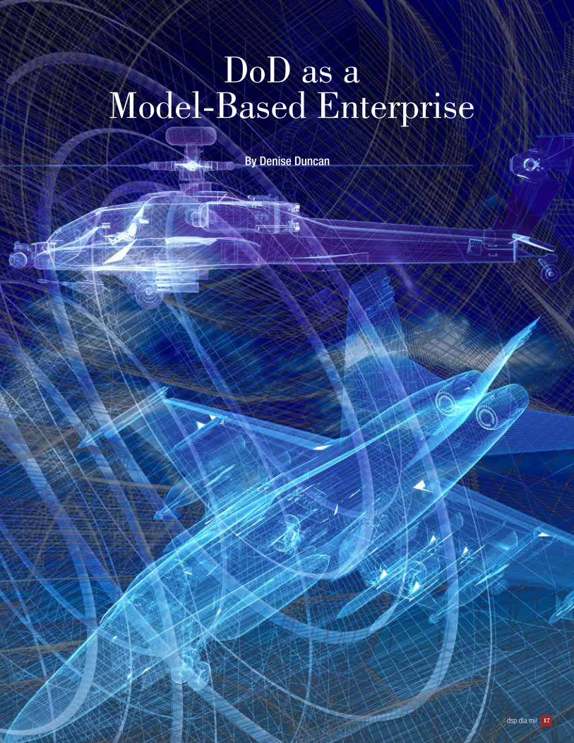
DoD as a Model-Based Enterprise
DSP JOURNAL October-December 201518
DDoD is one of the largest buyers of complex systems and the parts to maintain them; it
spends billions annually on weapons systems, spares, parts, and related supplies. These
systems are in active use for decades and must be ready for use at any time. Over the
entire life cycle of a given system, sustainment is the largest cost, surpassing even the
original purchase price. Sustainment costs can be as much as 60 to 80 percent of the total
life-cycle costs of a weapons system.
Costs during the sustainment phase can be driven by a number of factors, but techni-
cal data—for example, design and engineering models, manufacturing processes, and
maintenance instructions—are key. DoD has traditionally used two-dimensional (2D)
technical data, such as engineering drawings. Two-dimensional technical data were the
state of the art when many of the legacy systems were designed, and DoD’s policies, in-
frastructure, and staffing for technical data still reflect that 2D environment. For example,
many DoD programs required technical data to be delivered in 2D drawings, even though
contractors typically use three-dimensional (3D) models. To satisfy DoD’s deliverable
requirement, contractors converted their 3D models to 2D drawings.
Cycle times, errors, and costs can be reduced by the use of 3D models throughout the
product life cycle—from the start of system design through the disposal of the system.
The use of 3D models throughout the product life cycle is often identified as a model-
based enterprise (MBE) approach.
What Is MBE?MBE uses the 3D models initially created in the conceptual design phase and evolves
the models throughout the rest of the product life cycle (see Table 1). The MBE concept
evolved because, over the past several decades, major manufacturers have adopted 3D
models in computer-aided design (CAD), computer-aided engineering, computer-aided
manufacturing, and numerically controlled machines. Those who have implemented
MBE and some lean manufacturing techniques have seen a significant return on that
investment.
Fully implementing MBE means creating electronic models of early designs (in the con-
ceptual design phase) and using those models to facilitate collaboration on those designs.
Electronically shared 3D models enable collaboration on preliminary design, detailed/
engineering design, virtual prototyping, manufacturing process design, and maintenance
process design and documentation. During the sustainment phase, 3D models provide a
consistent representation of the product line for various operations and sustainment pro-
cesses. The models contain all of the information needed to define the product in a form
that allows the data to be automatically extracted for other uses, from virtual prototyping
to Interactive Electronic Technical Manuals. This is how MBE shortens schedules, re-
duces errors and miscommunication, and saves money.
dsp.dla.mil 19
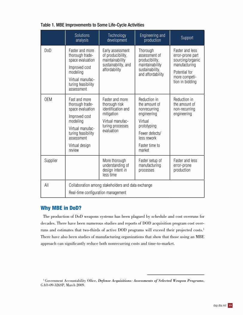
Table 1. MBE Improvements to Some Life-Cycle Activities
Solutions analysis
Technology development
Engineering and production Support
DoD Faster and more thorough trade-space evaluation
Improved cost modeling
Virtual manufac-turing feasibility assessment
Early assessment of producibility, maintainability sustainability, and affordability
Thorough assessment of producibility, maintainability sustainability, and affordability
Faster and less error-prone part sourcing/organic manufacturing
Potential for more competi-tion in bidding
OEM Fast and more thorough trade-space evaluation
Improved cost modeling
Virtual manufac-turing feasibility assessment
Virtual design review
Faster and more thorough risk identification and mitigation
Virtual manufac-turing processes evaluation
Reduction in the amount of nonrecurring engineering
Virtual prototyping
Fewer defects/ less rework
Faster time to market
Reduction in the amount of non-recurring engineering
Supplier More thorough understanding of design intent in less time
Faster setup of manufacturing processes
Faster and less error-prone production
All Collaboration among stakeholders and data exchange
Real-time configuration management
Why MBE in DoD?The production of DoD weapons systems has been plagued by schedule and cost overruns for
decades. There have been numerous studies and reports of DOD acquisition program cost over-
runs and estimates that two-thirds of active DOD programs will exceed their projected costs.1
There have also been studies of manufacturing organizations that show that those using an MBE
approach can significantly reduce both nonrecurring costs and time-to-market.
1 Government Accountability Office, Defense Acquisitions: Assessments of Selected Weapon Programs, GAO-09-326SP, March 2009.
DSP JOURNAL October-December 201520
Although specific industry return-on-investment analyses are held proprietarily, best-in-
class companies are using 3D models to achieve efficiencies. In a 2006 study,2 the Aberdeen
Group classified companies’ use of 3D technology and data as “best in class,” “average,” or
“laggards” for five parameters: (1) product revenue targets, (2) product cost targets, (3) devel-
opment cost targets, (4) launch dates, and (5) quality expectations.
According to the study, the group of companies that adopted 3D modeling early and inte-
grated it with all parts of the manufacturing process regularly hit revenue, cost, launch date,
and quality targets for at least 84 percent of their products.3
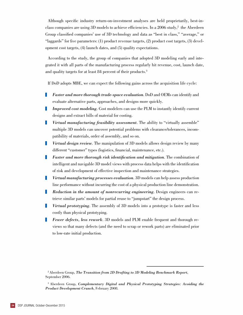
If DoD adopts MBE, we can expect the following gains across the acquisition life cycle:
▌ Faster and more thorough trade-space evaluation. DoD and OEMs can identify and
evaluate alternative parts, approaches, and designs more quickly.
▌ Improved cost modeling. Cost modelers can use the PLM to instantly identify current
designs and extract bills of material for costing.
▌ Virtual manufacturing feasibility assessment. The ability to “virtually assemble”
multiple 3D models can uncover potential problems with clearance/tolerances, incom-
patibility of materials, order of assembly, and so on.
▌ Virtual design review. The manipulation of 3D models allows design review by many
different “customer” types (logistics, financial, maintenance, etc.).
▌ Faster and more thorough risk identification and mitigation. The combination of
intelligent and navigable 3D model views with process data helps with the identification
of risk and development of effective inspection and maintenance strategies.
▌ Virtual manufacturing processes evaluation. 3D models can help assess production
line performance without incurring the cost of a physical production line demonstration.
▌ Reduction in the amount of nonrecurring engineering. Design engineers can re-
trieve similar parts’ models for partial reuse to “jumpstart” the design process.
▌ Virtual prototyping. The assembly of 3D models into a prototype is faster and less
costly than physical prototyping.
▌ Fewer defects, less rework. 3D models and PLM enable frequent and thorough re-
views so that many defects (and the need to scrap or rework parts) are eliminated prior
to low-rate initial production.
2 Aberdeen Group, The Transition from 2D Drafting to 3D Modeling Benchmark Report, September 2006.
3 Aberdeen Group, Complementary Digital and Physical Prototyping Strategies: Avoiding the Product Development Crunch, February 2008.
dsp.dla.mil 21
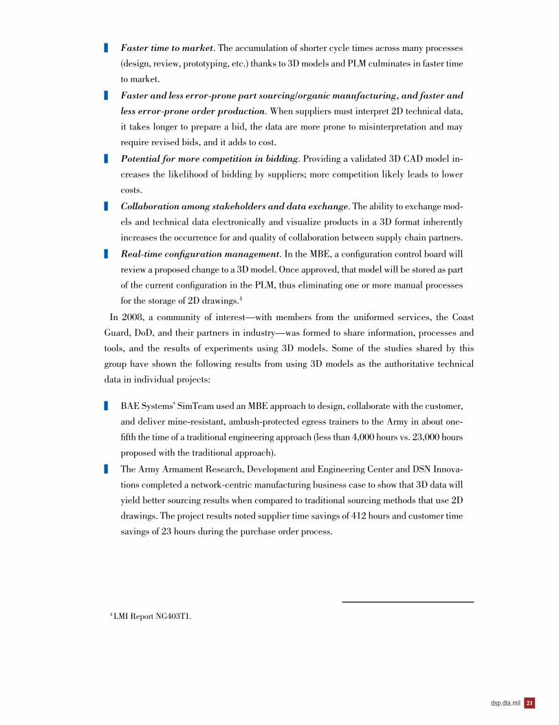
▌ Faster time to market. The accumulation of shorter cycle times across many processes
(design, review, prototyping, etc.) thanks to 3D models and PLM culminates in faster time
to market.
▌ Faster and less error-prone part sourcing/organic manufacturing, and faster and
less error-prone order production. When suppliers must interpret 2D technical data,
it takes longer to prepare a bid, the data are more prone to misinterpretation and may
require revised bids, and it adds to cost.
▌ Potential for more competition in bidding. Providing a validated 3D CAD model in-
creases the likelihood of bidding by suppliers; more competition likely leads to lower
costs.
▌ Collaboration among stakeholders and data exchange. The ability to exchange mod-
els and technical data electronically and visualize products in a 3D format inherently
increases the occurrence for and quality of collaboration between supply chain partners.
▌ Real-time configuration management. In the MBE, a configuration control board will
review a proposed change to a 3D model. Once approved, that model will be stored as part
of the current configuration in the PLM, thus eliminating one or more manual processes
for the storage of 2D drawings.4
In 2008, a community of interest—with members from the uniformed services, the Coast
Guard, DoD, and their partners in industry—was formed to share information, processes and
tools, and the results of experiments using 3D models. Some of the studies shared by this
group have shown the following results from using 3D models as the authoritative technical
data in individual projects:
▌ BAE Systems’ SimTeam used an MBE approach to design, collaborate with the customer,
and deliver mine-resistant, ambush-protected egress trainers to the Army in about one-
fifth the time of a traditional engineering approach (less than 4,000 hours vs. 23,000 hours
proposed with the traditional approach).
▌ The Army Armament Research, Development and Engineering Center and DSN Innova-
tions completed a network-centric manufacturing business case to show that 3D data will
yield better sourcing results when compared to traditional sourcing methods that use 2D
drawings. The project results noted supplier time savings of 412 hours and customer time
savings of 23 hours during the purchase order process.
4 LMI Report NG403T1.
DSP JOURNAL October-December 201522
▌ MBE data were used to create an immersive training environment for Army Stryker
maintenance personnel, which allowed personnel to train in a virtual environment.
This business case estimates a 25 percent reduction in field maintenance and repair
time and a yearly return on investment of $25 million if MBE data are reused in
interactive 3D models embedded in animated training files.
▌ PDES Inc. and ITI led an Air Force–sponsored project looking at technical data
exchange between suppliers and customers, specifically, the challenges and ineffi-
ciencies even in a model-based environment. The project team identified automation
opportunities and workflow enhancements that are estimated to save large programs
$27 million in nonrecurring engineering and more than $20 million in recurring
engineering.
Most recently, the Defense Wide Manufacturing Science and Technology Program re-
cently funded three projects that focus on data exchange processes, from the perspectives
of both government-to-government and government-to-industry or supplier.
▌ The first focused on 3D technical data for electrical systems, specifically electrical
wiring harnesses. It measured the cost of converting legacy technical data to standard
3D formats. It showed that the cost to develop translation software dropped steeply
after the first translator, so that a translator for a third legacy format cost about a half
a man-year in labor. The utility of using the PLCS format as the neutral-format “Ro-
setta Stone” for further translations was also proven to be both effective and efficient.
▌ The second investigated the validation and verification (V&V) of technical data pack-
ages delivered to the government. This project focused on the ability to perform V&V
on data exchanges, whether between different PLM formats, PMI within models, or
data from 2D formats remastered into 3D formats. This project showed that a PMO
with access rights to a supplier’s PLM could save more than $20 million over 5 years
by using its own PLM versus simply downloading the data to its LAN for sustainment
actions. Transferring entire models from the supplier’s PLM to the PMO’s PLM en-
sured that configuration management was maintained during engineering changes.
dsp.dla.mil 23
▌ The third project focused on MBE transfer capabilities (industry to industry)—
demonstration of data exchange and validation by an OEM and its suppliers. This
study found a time savings of about 12 percent by passing models up and down the
supply chain (from prime to supplier, and from supplier back to the prime along with
the manufactured item).
All of these studies and experiments taken together show that MBE offers a great deal
to DoD. It has been tested—this approach has been used in the DoD industrial base for
more than a decade—and it can be implemented using existing, commercially available
tools. MBE can potentially generate large returns on investment, and it can help meet
aggressive schedules for both initial production and sustainment. Various DoD organiza-
tions have been using 3D models on select acquisitions, and some have documented the
benefits. The time is right for programs to consider the use of MBE for the full life cycle
and for DoD to investigate the most efficient and effective ways to implement MBE.
About the Author
Denise Duncan has worked extensively on the application of data management principles to engineering and scientific data. She has authored standards, handbooks, and training materials in enterprise-level data management and knowledge management. Ms. Duncan is a senior fellow at LMI with more than 30 years of information systems management experience managing a wide variety of projects—from assisting senior leaders with portfolio management to strategic planning for chief information officers. She is the vice chair of the Enterprise Information Management and Interoperability Committee of SAE’s Aerospace Council; she is also the industry-data management section chair of NDIA’s Technical Information Division and serves on the board of the local chapter of Data Management Association–International.
DSP JOURNAL October-December 201524
Redesign of Air Force Test Set Achieves Savings and Improves
Topical Information on Standardization Programs
ProgramNews
Don’t Miss the Standardization in NATO Course
If you are interested in NATO standardization and want to gain familiarity with this fascinating
but complex subject, the introductory “Standardization in NATO” course is offered twice a year.
The 25th edition of the course will take place in Warsaw in spring 2016. The Polish Military
University of Technology, in collaboration with the Polish Ministry of Defence and the NATO
Standardization Office (NSO), offers this comprehensive course, accredited by NATO’s Allied
Command for Transformation.
The course analyzes standardization as a key element to achieve and maintain the compati-
bility, interchangeability, or commonality necessary to attain the required level of alliance in-
teroperability, and to optimize the use of resources, in the fields of operations, materiel, and
administration. It provides students with a clear knowledge of the NATO standardization struc-
ture, its processes and products, as well as the interdependencies with European and national
systems.
The course is aimed primarily at beginning practitioners who are relatively new to NATO stan-
dardization. Nevertheless, it can be useful for those already working in both NATO and stan-
dardization for several months. The course prepares practitioners for national standardization
positions such as custodian of a NATO standard or national representative to a NATO working
group or NATO standardization tasking authority. It also prepares practitioners for international
roles within NATO or the European Union, such as standardization working group chairperson
or a NATO staff position with some responsibilities in the area of standardization.
The course includes specific lectures on several key areas. One explains NATO’s standard-
ization documents development process, including consensus-based decision making. Lectures
on partners’ involvement and NATO’s use of civil standards demonstrate some of the bridges
between NATO and the rest of the standardization world. Practical hands-on work with the
NSO-protected website and the NATO Standardization Document Database ensure that course
members receive a firm grounding in these important tools. This approach is based on the
well-received hands-on workshop on the NATO Terminology Programme, also provided by NSO
personnel.
dsp.dla.mil 25
Experts from national standardization organizations present in-depth information on European
and national systems. An interactive visit to the Polish to Military Center for Standardization,
Quality Assurance and Codification offers first-hand information on the Polish standardization
system and its current activities. Throughout, the course reflects the most recent policy develop-
ments and takes into account evolving interoperability requirements.
Participants include personnel from NATO and partner nations. They, together with personnel
and experts from the NATO Standardization Office and national standardization organizations,
provide the course with a strong international character. Participants are encouraged to compare
challenges and share information and best practices. As with most professional courses, this
opportunity provides good practical insight and directly useful solutions to common challenges.
A well-organized social program offer many opportunities to build personal and professional
contacts in numerous NATO and partner countries. These currently include tours of the cities of
Warsaw and Krakow as well as hosted lunches and a cookout.
Application forms for the 25th edition of “Standardization in NATO” and additional informa-
tion will be found on the NSO website (https://nso.nato.int/nso/SOSite/WEBUpdate/NSOEvents.
html).
NATO Standardization Office Drafting Team Seeks Input
The North Atlantic Treaty Organization (NATO) Standardization Office has established a draft-
ing team to manage the update for AAP-03J, “Production, Maintenance and Management of
NATO Standardization Documents.”
While the United States is well represented in the drafting sessions with both the U.S. Military
Delegation and the Defense Standardization Program Office, additional input by defense activi-
ties that support NATO standardization is welcomed. Your input is invaluable to our continued
effort to work with allies and partners to ensure interoperability through standardization. Your
review and comments will provide the input needed to ensure that AAP-03K makes it easier to
conduct standardization business within NATO.
If you are interested in participating, please contact Latasha R. Beckman via e-mail at latasha.
[email protected], or by phone at 703-767-6872. As action officer, Ms. Beckman will ensure
that you are included in efforts to coordinate AAP-03K within the United States, as appropriate.
ProgramNews
DSP JOURNAL October-December 201526
Upcoming Events and Information
Events
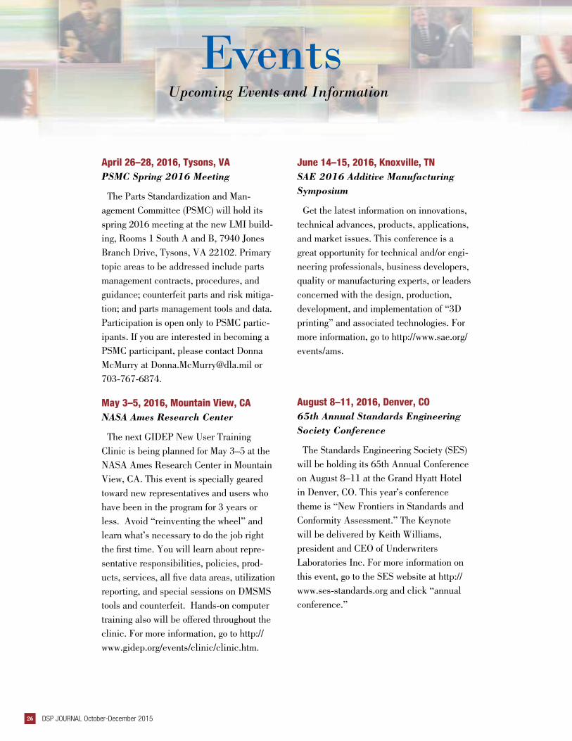
April 26–28, 2016, Tysons, VAPSMC Spring 2016 Meeting
The Parts Standardization and Man-agement Committee (PSMC) will hold its spring 2016 meeting at the new LMI build-ing, Rooms 1 South A and B, 7940 Jones Branch Drive, Tysons, VA 22102. Primary topic areas to be addressed include parts management contracts, procedures, and guidance; counterfeit parts and risk mitiga-tion; and parts management tools and data. Participation is open only to PSMC partic-ipants. If you are interested in becoming a PSMC participant, please contact Donna McMurry at [email protected] or 703-767-6874.
May 3–5, 2016, Mountain View, CANASA Ames Research Center
The next GIDEP New User Training Clinic is being planned for May 3–5 at the NASA Ames Research Center in Mountain View, CA. This event is specially geared toward new representatives and users who have been in the program for 3 years or less. Avoid “reinventing the wheel” and learn what’s necessary to do the job right the first time. You will learn about repre-sentative responsibilities, policies, prod-ucts, services, all five data areas, utilization reporting, and special sessions on DMSMS tools and counterfeit. Hands-on computer training also will be offered throughout the clinic. For more information, go to http://www.gidep.org/events/clinic/clinic.htm.
June 14–15, 2016, Knoxville, TNSAE 2016 Additive Manufacturing Symposium
Get the latest information on innovations, technical advances, products, applications, and market issues. This conference is a great opportunity for technical and/or engi-neering professionals, business developers, quality or manufacturing experts, or leaders concerned with the design, production, development, and implementation of “3D printing” and associated technologies. For more information, go to http://www.sae.org/events/ams.
August 8–11, 2016, Denver, CO65th Annual Standards Engineering Society Conference
The Standards Engineering Society (SES) will be holding its 65th Annual Conference on August 8–11 at the Grand Hyatt Hotel in Denver, CO. This year’s conference theme is “New Frontiers in Standards and Conformity Assessment.” The Keynote will be delivered by Keith Williams, president and CEO of Underwriters Laboratories Inc. For more information on this event, go to the SES website at http://www.ses-standards.org and click “annual conference.”

dsp.dla.mil 27
Upcoming Events and Information
Events
October 24–28, 2016, Washington, DC World Standards Week
Save the date—World Standards Week will take place the week of October 24, 2016. While many of the details are still being worked out, please “save the date” for what promises to be a comprehensive week of both meetings and events. A must attend for all standards professionals. For more information and event updates, go to http://www.ansi.org/wsweek.
December 5–8, 2016, Albuquerque, NM2016 DoD Maintenance Symposium
The mission of the 2016 DoD Mainte-nance Symposium is to create an envi-ronment that enables attendees to share relevant information, identify critical issues, discuss key topics, and increase their awareness of Department of Defense maintenance initiatives. Join military, government, and industry leaders and maintainers from all levels at this distinc-tive, first-class event—the maintenance community’s primary venue for networking and content sharing. For more information or registration details, go to http://www.sae.org/events/dod.

DSP JOURNAL October-December 201528
PeoplePeople in the Standardization Community
PeoplePeople in the Standardization Community
FarewellAlex Melnikow retired on February 3, 2016, after more than 40 years
of federal service. He began his career with the Tennessee Valley Author-ity (TVA), which he joined in 1975. After 7 years at TVA, he went on to hold various positions at the Naval Air Test Center and Defense Logistics Agency before coming to the Defense Standardization Program Office (DSPO) in 2007. While at DSPO, Mr. Melnikow was responsible for estab-lishing policy, guidance, and training for the Diminishing Manufacturing Sources and Material Shortages (DMSMS) program and led efforts to invig-orate proactive obsolescence management through enhanced engineering practices. We congratulate Alex on his retirement and wish him well in his future endeavors.
Charles Zegers retired after more than 30 years with the American Na-tional Standards Institute (ANSI). In his most recent position, he served as senior director for international policy and general secretary for the U.S. National Committee to the International Electrotechnical Commission. During his tenure at ANSI, Mr. Zegers served in various other positions, including director with staff responsibility for the Board of Standards Re-view and the Audit Accreditation Board and senior program administrator within various technical areas for the institute. Prior to joining ANSI, he also held positions with the American Society of Heating, Refrigeration and Air-Conditioning and the Edison Electric Institute. We wish him well in retirement.
dsp.dla.mil 29
Secure Biometric Information
Compact Biometric Messages
The Biometrically Enabled Coalition
BiometricsStandardization
Journal_1-13_Biometrics_Stan 6/12/13 9:09 AM Page 1
Upcoming IssuesCall for Contributors
We are always seeking articles that relate to our themes or other standardization topics. We invite anyone in-volved in standardization—government employees, military personnel, industry leaders, members of aca-demia, and others—to submit proposed articles for use in the DSP Journal. Please let us know if you would like to contribute.
Following are our themes for upcoming issues:
If you have ideas for articles or want more informa-tion, contact Tim Koczanski, Editor, DSP Journal, Defense Standardization Program Office, 8725 John J. Kingman Road, STOP 5100, Fort Belvoir, VA 22060-6220 or e-mail [email protected].
Our office reserves the right to modify or reject any submission as deemed appropriate. We will be glad to send out our editorial guidelines and work with any au-thor to get his or her material shaped into an article.
Upcoming IssuesCall for Contributors
Issue Theme
January/March 2016 Standardization Stars
April/June 2016 Interoperability
July/September 2016 Standards Policy
October/December 2016 Agency Standardization

DSP JOURNAL October-December 201530