Embed Size (px)
Citation preview

OPEN STANDARDS IN SIMULATION MODELICA AND FMI AS ENABLERS FOR VIRTUAL PRODUCT INNOVATION
Hubertus Tummescheit
Board member, Modelica Association & co-founder of Modelon
1

OVERVIEW
• Background and Motivation
• Introduction – why open standards matter
• Innovation in Model Based Design
• Modelica – the equation based modeling language
• The Functional-Mockup-Interface (FMI)
• Examples
• What’s next: upcoming innovations
• Conclusions
2
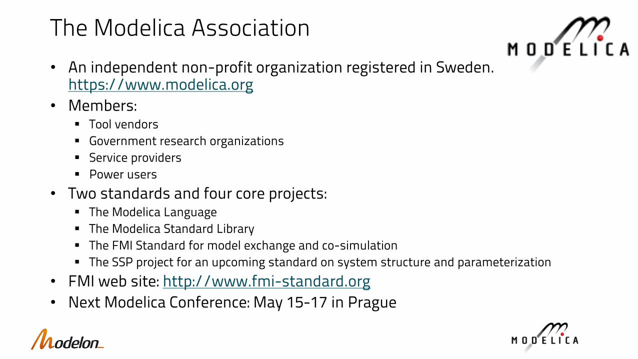
The Modelica Association
• An independent non-profit organization registered in Sweden. https://www.modelica.org
• Members: ▪ Tool vendors
▪ Government research organizations
▪ Service providers
▪ Power users
• Two standards and four core projects:▪ The Modelica Language
▪ The Modelica Standard Library
▪ The FMI Standard for model exchange and co-simulation
▪ The SSP project for an upcoming standard on system structure and parameterization
• FMI web site: http://www.fmi-standard.org
• Next Modelica Conference: May 15-17 in Prague

▪ System complexity increases
▪ Required time to market decreases (most industries)
▪ Without disruptive changes, an impossible equation to solve.
MOTIVATION: THE COMPLEXITY ISSUE
Source: DARPA AVM project
4
Large part of complexity is in software!

WHY OPEN STANDARDS ARE NEEDED
• Computer Aided Engineering is a very fragmented industry
• Tools evolved domain by domain
• Interoperability has been an afterthought, at best
• Today’s complex systems require interoperability!
• An everyday challenge for engineering design
• Open standards drastically reduce the cost of creating interoperability between tools
• There is an interplay with open source: open source can also increase the speed of software innovation
5
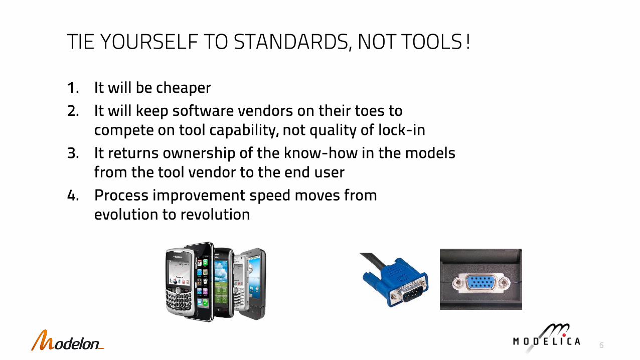
1. It will be cheaper
2. It will keep software vendors on their toes to compete on tool capability, not quality of lock-in
3. It returns ownership of the know-how in the modelsfrom the tool vendor to the end user
4. Process improvement speed moves from evolution to revolution
TIE YOURSELF TO STANDARDS, NOT TOOLS!
6

7
PRODUCT INNOVATION
Model Based Design: frontiers of virtual product design and what innovations are happening there

SYSTEM SIMULATION TECHNOLOGY WISH-LIST
• Multi-domain (electric, mechanic, thermal, fluid, etc.)
• Model fidelity adaptable to purpose (multi-fidelity)
• Scalable and robust simulation performance
• Re-usable models (model libraries, component based)
• Predictive (based on physics first principles)
• Extensible with proprietary IP and know-how
• Protect modeling investments over time
• Supported by community and open market
• Simple and robust connectivity
Modelica and FMI open standards meet all these!
8

Systems Engineering Interoperability
Functional
ElectromagneticFluid Mechanical
FMI, CoSim
ROM or RSM, CoSim
ROM = Reduced-Order ModelRSM = Response Surface Model FMI = Functional mock-up interfaceCoSim = Co-Simulation
3D Physics-based Models
System Software,Control & Operations
Architecture
System IntegrationMechatronics
„0D/1D“ Behavioural Models
VHDL-AMSSpice
s-parametersBlock-diagrams
State-graphs
Thermal
Interfaces?
Disciplines?
Tool Categories:• 0/1-D ODE Simulators• Multibody Simulators• Communication Simulators• HIL Simulators & SIL tool chains• Scientific Computation tools• Data analysis tools• Co-simulation Backplanes• Software development tools• Systems engineering tools• 3D Physics tools
(CFD, FEM in many domains)• Design & drawing, CAD• Data management: PLM, ALM, PDM• SDKs, legacy integration

Fidelity just right for purpose
Inherent support for working with mixed fidelities
• Get the architecture right
• Keep the design connected and consistent
• Continuously evaluate design against requirements
• Executable specs <-> Detailed design
Multi-domainMulti-domain by design
• Interaction and cross-dependencies betweensubsystems and physical domains captured
• Facilitates simultaneous engineering
• Allow for integrated design and optimization
Shift control
Cooling
Hybrid electric
Gearbox
Hydraulics
Engine
A/C
KEYS TO SYSTEMS DESIGN AND ENGINERING
BEHAVIORAL – PARAMETRIC – VERIFICATION
SY
STE
M –
SU
BS
YS
TEM
–P
AR
T
Design, simulation, analysis
Formal and open description
• Physics capture
• Constraint and cost definition
• Analysis and decision support
• Reduction/elemination of real tests
Examples:
• Dynamic simulation
• Steady-state
• Optimization
• Realtime/XIL
• Controls design
• Robust design
• Requirements definition
• Formal analysis 10

THE MODELICA LANGUAGE
A high-level language to develop physics based system models from architectural design to the component level
11

MODELICA: THE OPEN STANDARD FOR SYSTEMS MODELING
• Non-proprietary open standard, maintained by the Modelica Association (www.modelica.org)
• Object oriented modeling language
• Declarative: describes what something is, not how to solve it
• Non-causal and equation based
• First principles (mass, energy, momentum balances)
• Supports multi-domain modeling
• Large community and ecosystem of services, tools and model libraries
12

• Dymola® by Dassault Systèmes
• IGNITE by Ricardo Software
• MapleSim® by MapleSoft®
• MWorks by Suzhou Tongyuan
• OPTIMICA® Toolkit by Modelon
• Simplorer by ANSYS
• SimulationX® by ESI-ITI GmbH
• SolidThinking Activate by Altair
• Wolfram SystemModeler by Wolfram
• JModelica.org by Modelon
• OpenModelica by the OM Consortium
More tools coming (e.g. Amesim by Siemens LMS)
Co
mm
erc
ial
Op
en
So
urc
e
13

LEVERAGE EXISTING MODELS AND KNOW-HOW
• Off-the-shelf model libraries and components reduces maintenance
• Focus on core knowledge to grow the competitive edge
• Build innovative systems from standard component models
14
Free open source
Commercial off-the-shelf
Consulting services
Partners / suppliers /customers / academia
In-house
• Knowledge stored in Modelica model libraries
• Accessible, persistent, extensible in-house IP

ARCHITECTURES DESIGN & EXPLORATION
15
Organization of model into interfaces and templates promotes broader applicability and reusability reducing modeling effort in a product line context for re-validation.
Modelica language support for abstract typing; strong typing (guarantees for plug-compatibility of models) enables rigorous checks for subsystem compatibility and interface consistency
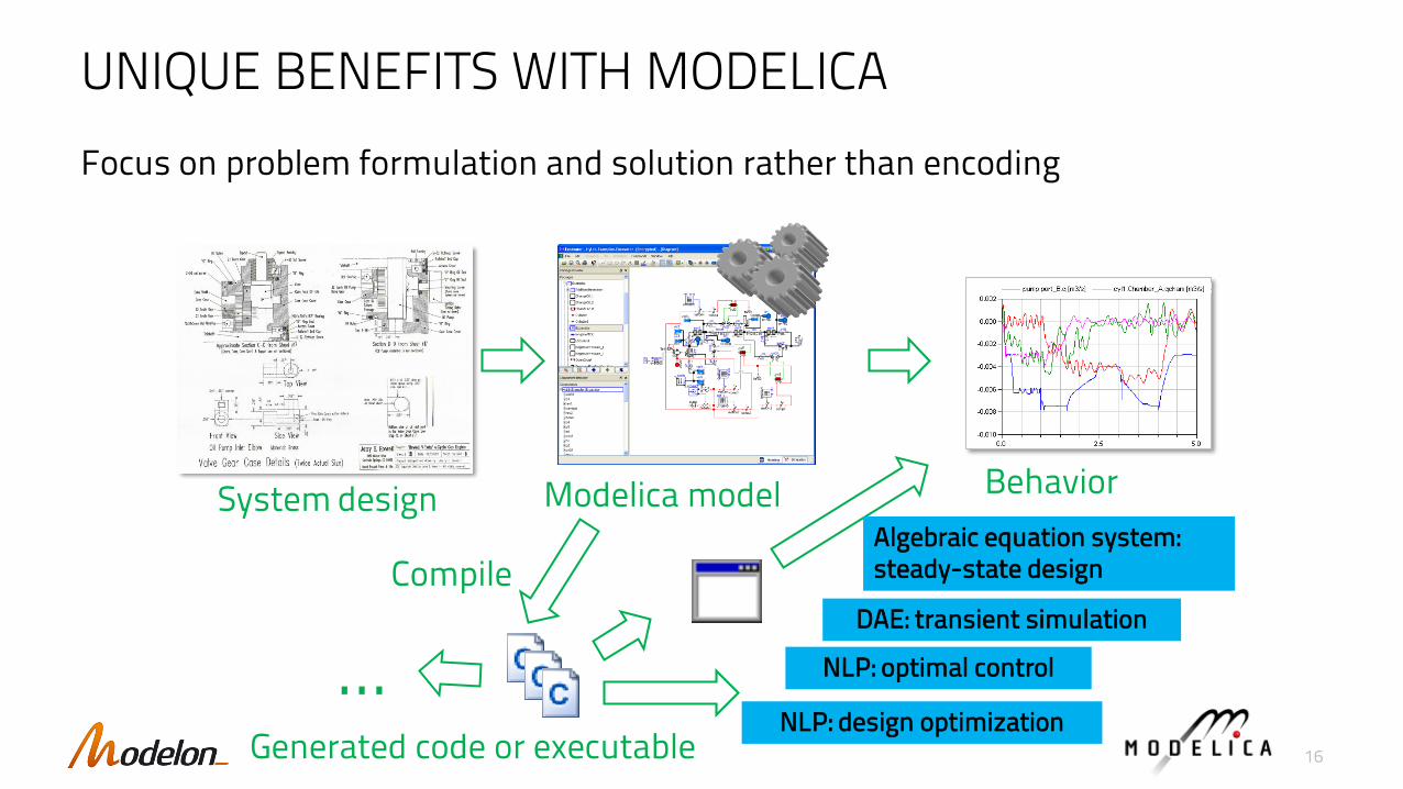
UNIQUE BENEFITS WITH MODELICA
Focus on problem formulation and solution rather than encoding
Modelica model BehaviorSystem design
NLP: optimal control
DAE: transient simulation
Algebraic equation system: steady-state design
NLP: design optimization
...Generated code or executable
Compile
16

Efficient simulation: Differential Algebraic Equation Case
Modelica tools use symbolic manipulation to generate efficient simulation code
17

OPERATIONAL OPTIMIZATION & OPTIMAL CONTROL
Collocation of finite elements for trajectory optimization
18

GOING TO THE MOON
19
Courtesy: Mitsubishi Electric Research Lab
The optimized trajectory in the rotating frame of PCR3BP involving the Earth, moon and the space probe. The space probe receives two consecutive gravity assists, and is then pushed onto the stable manifold of the L1 periodic orbit. Optimized delta-Vs then put on the low lunar orbit using the unstable dynamics near L1.
Given a Lyapunov orbit around L1, find the minimum fuel for a transfer into an orbit around the moon (m2). The controls are given as two discontinuous changes in velocity, corresponding to two rocket bursts.
Controls by Dv
Lyapunov orbit
MoonEarth
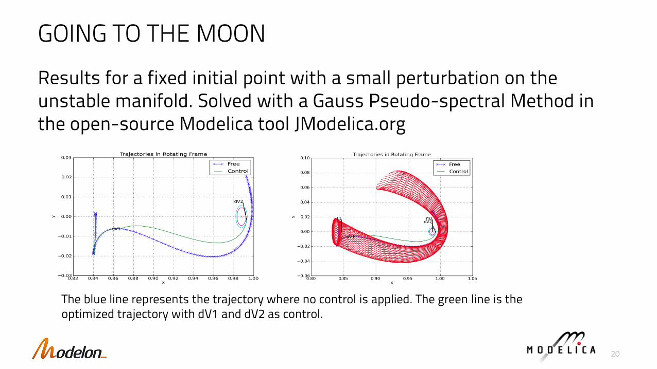
GOING TO THE MOON
Results for a fixed initial point with a small perturbation on the unstable manifold. Solved with a Gauss Pseudo-spectral Method in the open-source Modelica tool JModelica.org
20
The blue line represents the trajectory where no control is applied. The green line is the optimized trajectory with dV1 and dV2 as control.
THE FUNCTIONAL MOCKUP-INTERFACE
An API for executable models for model exchange and co-simulation
21

FMI: THE OPEN STANDARD FOR MODEL DEPLOYMENT
FMI™ is:
• A tool independent standard for model exchange and co-simulation
• Currently supported by more than 95 tools
• Strong support from automotive industry
FMI™ enables:
• Model-sharing and IP protection
• Deployment in different applications
• Streamlined tool connectivity
22
WWW.FMI-STANDARD.ORG
22

What is FMI?
• FMI is a standard interface to enable the exchange of compiled models between tools, and for co-simulation▪ Has been adopted by over 95 CAE tools as a supported interface
▪ Is propagated by several industrial consortia (ProSTEP iVIP, GAAG)
• The FMI licensing model revolutionizes the business model for enterprise model deployment▪ Model content and execution can be shared freely within the extended enterprise
▪ Model authoring is done on typical CAE tools
• FMI is applicable to a much broader set of tools than Modelica: FEM, CFD, Controls & Software development, …

EXCERPT OF FMI-COMPATIBLE TOOLS
24
95+ toolsSupported by different tool classes:• 0/1-D ODE Simulators• Multibody Simulators• HIL Simulators /SIL tool chains• Scientific Computation tools• Data analysis tools• Co-simulation Backplanes• Software development tools• Systems engineering tools• SDKs, legacy integration

Combined simulation for system integration
Solution▪ As a universal solution to this problem the Functional Mockup Interface (FMI) was developed
by the EU-project MODELISAR, and is now maintained by the Modelica® Association
FMI USE CASE I: COMBINE MULTIPLE DOMAINS
?
supplier1 supplier2 supplier3 supplier4 supplier5
OEM
supplier1
tool 1
supplier2 supplier3 supplier4 supplier5
tool 2 tool 3 tool 4 tool 5
FMI OEM
25

FMI USE CASE II: CONNECT SYSTEM LEVEL WITH 3D
• Combine different modeling domains into coherent co-simulation (cyber-physical systems)
▪ Physical models, 0D/1D to 3D (but not 3D to 3D!)
▪ Models of controls & software
FEA
CFD
Modelica / 1-D Systems Simulation
FMI-based System Simulation
Block DiagramsControls
26

FMI USE CASE III: COMBINE SOFTWARE & PHYSICS• FMI export support from Controls Tools:
▪ Matlab/Simulink through FMIT Coder (Modelon)▪ SCADE Suite (safety critical applications) ▪ IBM Rational Rhapsody▪ Easy to integrate manually written control code
through FMI-wrappers
• FMI supported by most major HIL Vendors▪ DSPACE▪ National Instruments▪ Concurrent▪ IPG▪ Speedgoat
• FMI for ECU virtualization▪ Silver by Qtronic▪ ETAS tools (Bosch)
27
MIL, SIL and HIL

FMI: A BUSINESS MODEL INNOVATION
• FMI-compliant tools often allow liberally licensed export of models for distribution in the organization
• Exported FMU’s most often don’t require a license from the model authoring tool
• Deployment from few simulation specialists to designers, domain specialists, control engineers
• One FMU used by many engineers (control design)
• One FMU run on many cores (robust design)
28

TYPICAL FMI-BASED WORKFLOWS
Model Authoring Tool(s)
Low-cost Model Execution PlatformMay combine FMUs from several tools
Export model as freely licensed FMU
• Additional work flow automation for ▪ pre-processing, ▪ model calibration, ▪ post-processing, ▪ analysis, ▪ automated reporting▪ automated requirements verification
• True democratization of simulation
• Greatly improved utilization of models
29

FMI TOOLCHAIN SOLUTIONS
30
” FMI reduces the integration efforts and therefore allows BMW to concentrate on the core competences of the development. Several projects at BMW have confirmed that FMI is our best chance yet to establish cross-domain simulations throughout the vehicle development process.
Stefan-Alexander Schneider, BMW
CUSTOM APPLICATION
LIBRARY
DLLXMLDLLXML
FMU
DLLXML
FMI LIBRARY / FMI .NET / FMI C++ / pyFMI
FM
U Im
po
rt A
PI
ZIP
CX
ML
Loaded FMU
DLLXML
Real-Time simulation
Steady-state
Custom simulator
Graphical User Interface
MODELING ENVIRONMENT
One Model, many uses!

FLEXIBILITY OF MODELICA KEY TO VIRTUAL DESIGN OF INNOVATIVE PRODUCTS
Examples from many industries where Modelica and FMI helped design innovative products
31

The DLR Robotic Motion Simulator - Utilizing Modelica for the development
The DLR Robot Motion Simulator:
• Industrial robot based motion simulator
• Linear axis + 6 axis robot
• 500 kg payload
• Additionally a version with a DA42
cockpit has been developed Workspace optimization
Cell dimensionsSystem simulation
Working point definition
courtesy: DLR - Institute of System Dynamics and Control (www.dlr.de/sr)
DLR.de • Chart 32

Optimization based Pathplanning with Modelica
Flight dynamics simulation
Pilot commands
Forces andangular velocities
Vehicle dynamics simulation
Robot kinematics
Motion planning
Robotangles
courtesy: DLR - Institute of System Dynamics and Control (www.dlr.de/sr)DLR.de • Chart 33

DLR.de • Chart 34

DLR ROboMObil - Robotic Electric Vehicle for future mobility research
• Four "wheel robots":▪ Wheel hub drives (each 160Nm)▪ Independently actuated steering (steering angle: -25c…95c)
• Autonomous driving through camera system and image recognition
• Various by-wire input devices combined with force feedbackand driver assistance as well as remote control
DLR.de • Chart 35
courtesy: DLR - Institute of System Dynamics and Control (www.dlr.de/sr)

DLR ROboMObil – Designed and Operated with Modelica
Model of Vehicle Dynamics, Actuator,
Sensors,...
Vehicle Control
Optimization Tools
State Estimation Hardware-in-the-loop (HIL)
Rapid Prototype Controllers
Embedded Controllers
Modelica Libraries
„Desktop PC“ (off-line evaluation)
Code Export
Vehicle Model
Visualisation
Target Device
courtesy: DLR - Institute of System Dynamics and Control (www.dlr.de/sr)
DLR.de • Chart 36

DLR ROboMObil - Robotic Electric Vehicle for future mobility research
DLR.de • Chart 37
courtesy: DLR - Institute of System Dynamics and Control (www.dlr.de/sr)
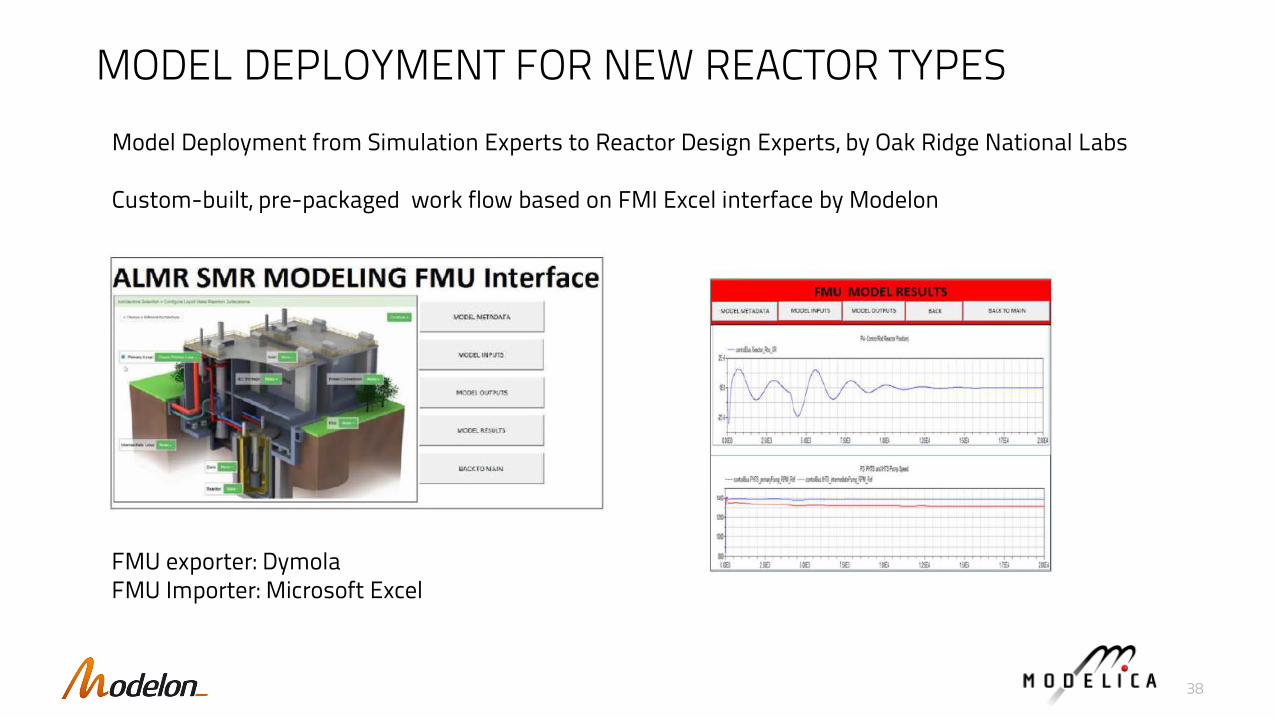
MODEL DEPLOYMENT FOR NEW REACTOR TYPES
Model Deployment from Simulation Experts to Reactor Design Experts, by Oak Ridge National Labs
Custom-built, pre-packaged work flow based on FMI Excel interface by Modelon
FMU exporter: DymolaFMU Importer: Microsoft Excel
38

• Coal-fired power plant with CO2 separation
▪ Integration with a carbon capture library
▪ Use case based on mix of off-the shelf libraries & specialized solution
39
COAL-FIRED POWER PLANT WITH CARBON CAPTURE
Capture Plant Model built with Modelon Post-Combustion Carbon Capture Solution

Fuel Cell SLDM for controls
Eborn, et. al: System Level Dynamic Modeling of Fuel Cell Power Plants,
In Proc. of American Controls Conference, Denver, CO, 2003.
• System model includes; fuel processing, stack, power section and thermal management
• Detailed model with >20000 equations, >500 dynamic states
• System model the enabler for innovative integrated solutions
FPS
ERDTMS
CSA
PCS
40

UPCOMING INNOVATIONS
41
FEA
CFD
Modelica / 1-D Systems Simulation
Block DiagramsControls
More connectivity between 3-D tools and system simulation tools
Requirements Validated system
DesignConnection between Systems engineering and system simulation
Connection to PLM & PDM systems, possibly via OSLC
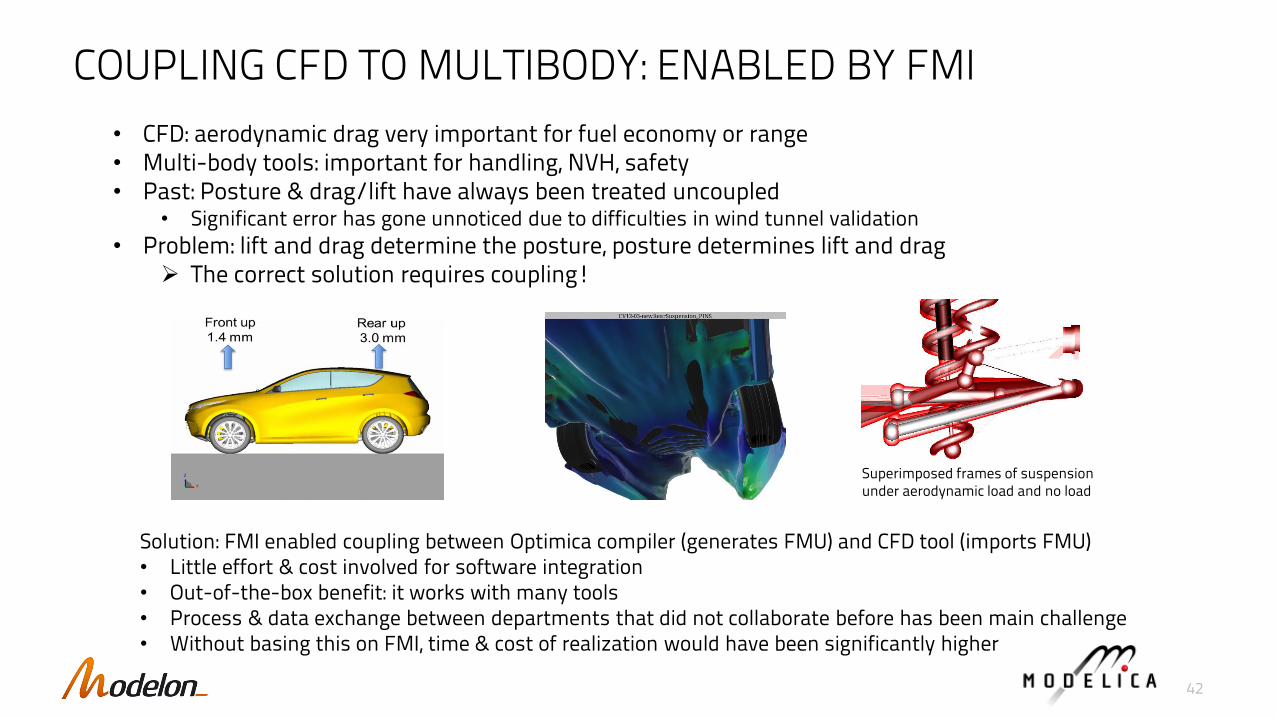
COUPLING CFD TO MULTIBODY: ENABLED BY FMI
• CFD: aerodynamic drag very important for fuel economy or range• Multi-body tools: important for handling, NVH, safety• Past: Posture & drag/lift have always been treated uncoupled
• Significant error has gone unnoticed due to difficulties in wind tunnel validation
• Problem: lift and drag determine the posture, posture determines lift and drag➢ The correct solution requires coupling!
Solution: FMI enabled coupling between Optimica compiler (generates FMU) and CFD tool (imports FMU)• Little effort & cost involved for software integration• Out-of-the-box benefit: it works with many tools• Process & data exchange between departments that did not collaborate before has been main challenge• Without basing this on FMI, time & cost of realization would have been significantly higher
Superimposed frames of suspension under aerodynamic load and no load
42

SYSTEMS ENGINEERING & SIMULATION
• Today: connectivity between simulation and system engineering tools is ad-hoc, pretty much non-existent.
• Linking requirements to Model Based Design has a big potential to improve productivity
• Connectivity built on Modelica, FMI and OSLC: 3 open standards!
• Closing the Design Cycle Loop with Executable Requirements and OSLC (Incose IW 2017 workshop presentation jointly by Modelon, Procter & Gamble and The Reuse Company)
43

SUMMARY: HOW MODELICA AND FMI PROMOTE INNOVATION
• Modelica enables innovation because,
▪ It is a high-level description of the model
▪ It is open to be connected and optimized for many solvers and algorithms, without a need to change the high-level description
▪ Can describe architectures and variants efficiently
• FMI enables innovation because
▪ It makes all the low-level interaction easy and standardized
▪ It is at the same time so simple that it is easy to adopt, and powerful enough to solve tough problems
▪ Applies to a much broader class of tools than Modelica
• Modelica and FMI jointly enable process innovation because the cost of interoperability is lowered significantly
44