Embed Size (px)
Citation preview

Open Research OnlineThe Open University’s repository of research publicationsand other research outputs
Model-Based Analysis of Role-Based Access ControlThesisHow to cite:
Montrieux, Lionel (2013). Model-Based Analysis of Role-Based Access Control. PhD thesis The Open University.
For guidance on citations see FAQs.
c© 2013 The Open University
Version: Version of Record
Copyright and Moral Rights for the articles on this site are retained by the individual authors and/or other copyrightowners. For more information on Open Research Online’s data policy on reuse of materials please consult the policiespage.
oro.open.ac.uk

Model-Based Analysis ofRole-Based Access Control
Lionel Montrieux
A thesis submitted to The Open University
for the degree of
Doctor of Philosophy in Computing
May 2013


iii
Abstract
Model-Driven Engineering (MDE) has been extensively studied. Many directions have
been explored, sometimes with the dream of providing a fully integrated approach for
designers, developers and other stakeholders to create, reason about and modify models
representing software systems.
Most, but not all, of the research in MDE has focused on general-purpose languages
and models, such as Java and UML. Domain-specific and cross-cutting concerns, such
as security, are increasingly essential parts of a software system, but are only treated as
second-class citizens in the most popular modelling languages. Efforts have been made
to give security, and in particular access control, a more prominent place in MDE, but
most of these approaches require advanced knowledge in security, programming (often
declarative), or both, making them difficult to use by less technically trained stakeholders.
In this thesis, we propose an approach to modelling, analysing and automatically fixing
role-based access control (RBAC) that does not require users to write code or queries
themselves. To this end, we use two UML profiles and associated OCL constraints that
profide the modelling and analysis features. We propose a taxonomy of OCL constraints
and use it to define a partial order between categories of constraints, that we use to
propose strategies to speed up the models’ evaluation time. Finally, by representing OCL
constraints as constraints on a graph, we propose an automated approach for generating
lists of model changes that can be applied to an incorrect model in order to fix it. All
these features have been fully integrated into a UML modelling IDE, IBM Rational
Software Architect.

iv

v
Declaration
All the work in this dissertation describes original contributions of the
author.
• Montrieux, Lionel; Wermelinger, Michel and Yu, Yijun (2011). Tool
support for UML-based specification and verification of role-based access
control properties. In: 8th European Software Engineering Conference
and the ACM SIGSOFT Symposium on the Foundations of Software
Engineering, pp. 456-459, 4-9 Sep 2011, Szeged, Hungary (tool demo).
• Montrieux, Lionel; Wermelinger, Michel and Yu, Yijun (2011). Challenges
in Model-Based Evolution and Merging of Access Control Policies. In:
12th International Workshop on Principles on Software Evolution @
ESEC/FSE 2011, pp. 116-120, 5-6 Sep 2011, Szeged, Hungary.
• Montrieux, Lionel; Yu, Yijun; Wermelinger, Michel and Hu, Zhenjiang
(2013). Issues in representing domain-specific concerns in model-driven
engineering. In: 5th Workshop on Modeling in Software Engineering @
ICSE 2013, 18-19 May 2013, San Francisco.
• Montrieux, Lionel; Yu, Yijun and Wermelinger, Michel (2013). Developing
a domain-specific plug-in for a modelling platform: the good, the bad,
the ugly. In: 3rd Workshop on Developing Tools as Plug-ins @ ICSE
2013, 21 May 2013, San Francisco.

vi

vii
Acknowledgements
I would like to thank my supervisors, Michel Wermelinger and Yijun Yu, as well as
Charles Haley, for their guidance, comments, reviews, discussions and advice, and for
pushing me to finish this thesis. It would not have happened without their invaluable
support.
A special thanks goes to my family and friends; to my partner Jessica Hardaway, for
her support and for occasionally forcing me to take a day off; to Stefan Kreitmayer for
proofreading a few of my chapters instead of writing his own dissertation; to Jonathan
Fine for his extensive knowledge of LATEX and typesetting in general; to the postgraduate
students community at The Open University, and particularly those from the Computing
Department.
Outside of The Open University, I want to thank the members of the Software
Engineering for Critical Systems group at T.U. Dortmund, and in particular Jan Jurjens
and Sven Wenzel, for their valuable input on UMLsec and access control modelling. I am
also grateful to Zhenjiang Hu from NII, Japan for the stimulating discussions we had on
bidirectional graph transformations.
Finally, writing this dissertation would not have been possible without the help,
support and encouragement of the Computing Department at The Open University.

viii
Contents
List of figures xvii
List of tables xxi
1. Introduction 3
1.1. Motivation . . . . . . . . . . . . . . . . . . . . . . . . . . . . . . . . . . . 4
1.2. Research Objectives . . . . . . . . . . . . . . . . . . . . . . . . . . . . . . 7
1.3. Organisation of this Dissertation . . . . . . . . . . . . . . . . . . . . . . . 11
2. Literature Review 13
2.1. Model-Driven Engineering . . . . . . . . . . . . . . . . . . . . . . . . . . 14
2.1.1. MDE using OMG Standards . . . . . . . . . . . . . . . . . . . . . 16
2.1.2. Model Transformations as Graph Transformations . . . . . . . . . 18
2.1.3. Inconsistency Detection and Resolution . . . . . . . . . . . . . . . 19
2.2. Access Control . . . . . . . . . . . . . . . . . . . . . . . . . . . . . . . . 24
2.2.1. Authentication and Authorisation . . . . . . . . . . . . . . . . . . 25
2.2.2. Discretionary Access Control . . . . . . . . . . . . . . . . . . . . . 26
2.2.3. Mandatory Access Control . . . . . . . . . . . . . . . . . . . . . . 26
2.2.4. Role-Based Access Control . . . . . . . . . . . . . . . . . . . . . . 27
2.2.5. Extensions to RBAC . . . . . . . . . . . . . . . . . . . . . . . . . 34
2.2.6. Attribute-Based Access Control . . . . . . . . . . . . . . . . . . . 35
ix

x Contents
2.2.7. Access Control Properties Analysis . . . . . . . . . . . . . . . . . 36
2.3. Access Control and MDE . . . . . . . . . . . . . . . . . . . . . . . . . . . 38
2.3.1. Shin and Ahn’s RBAC Representation . . . . . . . . . . . . . . . 38
2.3.2. UMLsec . . . . . . . . . . . . . . . . . . . . . . . . . . . . . . . . 39
2.3.3. SecureUML . . . . . . . . . . . . . . . . . . . . . . . . . . . . . . 39
2.3.4. Cirit and Buzluca’s RBAC Profile . . . . . . . . . . . . . . . . . . 40
2.3.5. RBAC Patterns on UML . . . . . . . . . . . . . . . . . . . . . . . 41
2.3.6. Representing RBAC using Aspect-Oriented Modelling . . . . . . . 41
2.3.7. UML to Alloy . . . . . . . . . . . . . . . . . . . . . . . . . . . . . 42
2.3.8. Constraint-Focused Approaches . . . . . . . . . . . . . . . . . . . 42
2.3.9. Discussion . . . . . . . . . . . . . . . . . . . . . . . . . . . . . . . 44
3. Modelling Domain-Specific Concerns 47
3.1. A Sample UML Model . . . . . . . . . . . . . . . . . . . . . . . . . . . . 52
3.2. A Methodology for DSML Development Using UML Profiles . . . . . . . 54
3.2.1. The Meta-Model . . . . . . . . . . . . . . . . . . . . . . . . . . . 54
3.2.2. OCL Constraints . . . . . . . . . . . . . . . . . . . . . . . . . . . 56
3.3. The rbacDSML Profile . . . . . . . . . . . . . . . . . . . . . . . . . . . . . 58
3.3.1. UML Profiles Notation . . . . . . . . . . . . . . . . . . . . . . . . 58
3.3.2. Meta-Model . . . . . . . . . . . . . . . . . . . . . . . . . . . . . . 59
3.3.3. OCL Constraints . . . . . . . . . . . . . . . . . . . . . . . . . . . 61
3.3.4. RBAC Modelling with rbacDSML for the Sample Application . . . 63
3.4. The rbacUML Profile . . . . . . . . . . . . . . . . . . . . . . . . . . . . . 64
3.4.1. Meta-Model . . . . . . . . . . . . . . . . . . . . . . . . . . . . . . 65
3.4.2. OCL Constraints . . . . . . . . . . . . . . . . . . . . . . . . . . . 68
3.4.3. Sample application with rbacUML . . . . . . . . . . . . . . . . . . 69
3.5. A Taxonomy of OCL Constraints . . . . . . . . . . . . . . . . . . . . . . 72
3.5.1. Well-formedness . . . . . . . . . . . . . . . . . . . . . . . . . . . . 75

Contents xi
3.5.2. Verification . . . . . . . . . . . . . . . . . . . . . . . . . . . . . . 77
3.5.3. Satisfiability . . . . . . . . . . . . . . . . . . . . . . . . . . . . . . 78
3.5.4. Completeness . . . . . . . . . . . . . . . . . . . . . . . . . . . . . 79
3.5.5. Coverage . . . . . . . . . . . . . . . . . . . . . . . . . . . . . . . . 79
3.5.6. Redundancy . . . . . . . . . . . . . . . . . . . . . . . . . . . . . . 81
3.5.7. User-Defined Queries . . . . . . . . . . . . . . . . . . . . . . . . . 82
3.5.8. Evaluation of OCL Queries . . . . . . . . . . . . . . . . . . . . . 82
3.6. Discussion . . . . . . . . . . . . . . . . . . . . . . . . . . . . . . . . . . . 85
4. Fixing Models 89
4.1. Overview of the Solution . . . . . . . . . . . . . . . . . . . . . . . . . . . 90
4.2. Generating Fixes for Individual Constraints . . . . . . . . . . . . . . . . 92
4.2.1. Graph Representation of Constraints . . . . . . . . . . . . . . . . 92
4.2.2. Generating Possible Fixes . . . . . . . . . . . . . . . . . . . . . . 103
4.3. Fixing an Entire Model . . . . . . . . . . . . . . . . . . . . . . . . . . . . 121
4.3.1. Building a Solution Tree . . . . . . . . . . . . . . . . . . . . . . . 122
4.3.2. Termination Guarantee . . . . . . . . . . . . . . . . . . . . . . . . 125
4.3.3. Avoiding Duplicate Effort . . . . . . . . . . . . . . . . . . . . . . 126
4.4. Solutions Ordering . . . . . . . . . . . . . . . . . . . . . . . . . . . . . . 128
4.4.1. Number of Fixes . . . . . . . . . . . . . . . . . . . . . . . . . . . 128
4.4.2. Cost of Fixes . . . . . . . . . . . . . . . . . . . . . . . . . . . . . 129
4.4.3. Type of Changes . . . . . . . . . . . . . . . . . . . . . . . . . . . 129
4.4.4. Location of Changes . . . . . . . . . . . . . . . . . . . . . . . . . 130
4.4.5. Ordering rbacDSML Models Solutions . . . . . . . . . . . . . . . . 130
4.5. Improvements . . . . . . . . . . . . . . . . . . . . . . . . . . . . . . . . . 131
4.5.1. Error Prioritisation . . . . . . . . . . . . . . . . . . . . . . . . . . 131
4.5.2. Elimination of Undesirable Solutions . . . . . . . . . . . . . . . . 132
4.5.3. Searching for Good Solutions First . . . . . . . . . . . . . . . . . 135

xii Contents
4.6. How to Present Solutions . . . . . . . . . . . . . . . . . . . . . . . . . . . 138
5. Tool Support 143
5.1. Choosing the Right Platform . . . . . . . . . . . . . . . . . . . . . . . . . 144
5.1.1. Plug-In rather than Standalone . . . . . . . . . . . . . . . . . . . 145
5.1.2. Comparing Available Modelling Environments . . . . . . . . . . . 145
5.2. The rbacUML Plug-In . . . . . . . . . . . . . . . . . . . . . . . . . . . . 148
5.2.1. The Rational Software Architect Modelling Stack . . . . . . . . . 148
5.2.2. The UML Profiles . . . . . . . . . . . . . . . . . . . . . . . . . . . 149
5.2.3. Visualisation of Large Configurations . . . . . . . . . . . . . . . . 151
5.2.4. Import from LDIF . . . . . . . . . . . . . . . . . . . . . . . . . . . 151
5.2.5. Selective Evaluation of OCL Queries . . . . . . . . . . . . . . . . 152
5.2.6. Model Generator . . . . . . . . . . . . . . . . . . . . . . . . . . . 153
5.2.7. Fixing Incorrect Models . . . . . . . . . . . . . . . . . . . . . . . 153
5.3. Working with Rational Software Architect . . . . . . . . . . . . . . . . . 153
5.3.1. The Good . . . . . . . . . . . . . . . . . . . . . . . . . . . . . . . 154
5.3.2. The Bad, and the Ugly . . . . . . . . . . . . . . . . . . . . . . . . 156
5.3.3. Discussion . . . . . . . . . . . . . . . . . . . . . . . . . . . . . . . 159
5.4. rbacUML Evaluation Performance . . . . . . . . . . . . . . . . . . . . . . 160
5.4.1. Evaluation of each Type of Query . . . . . . . . . . . . . . . . . . 162
5.4.2. Correct v. Incorrect Models . . . . . . . . . . . . . . . . . . . . . 164
5.4.3. Discussion . . . . . . . . . . . . . . . . . . . . . . . . . . . . . . . 167
5.5. Fixing Performance . . . . . . . . . . . . . . . . . . . . . . . . . . . . . . 167
5.5.1. OCL Constraint Selection . . . . . . . . . . . . . . . . . . . . . . 171
5.5.2. Traversal Strategies . . . . . . . . . . . . . . . . . . . . . . . . . . 172
5.5.3. The NoChangeRbacDSML extension of the rbacDSML Profile . . . . 176
5.5.4. Discussion . . . . . . . . . . . . . . . . . . . . . . . . . . . . . . . 178

Contents xiii
5.6. A Real-Life Case Study . . . . . . . . . . . . . . . . . . . . . . . . . . . . 179
5.6.1. Lessons Learned . . . . . . . . . . . . . . . . . . . . . . . . . . . . 185
6. Conclusions 187
6.1. Future Work . . . . . . . . . . . . . . . . . . . . . . . . . . . . . . . . . . 189
6.1.1. Transformations . . . . . . . . . . . . . . . . . . . . . . . . . . . . 189
6.1.2. Translating OCL Constraints . . . . . . . . . . . . . . . . . . . . 192
6.1.3. Support for other Access Control Models . . . . . . . . . . . . . . 194
Bibliography 195
A. rbacDSML OCL Constraints 211
A.1. Well-Formedness . . . . . . . . . . . . . . . . . . . . . . . . . . . . . . . 212
A.1.1. Activated roles must be assigned to the user . . . . . . . . . . . . 212
A.1.2. SSoD . . . . . . . . . . . . . . . . . . . . . . . . . . . . . . . . . . 213
A.1.3. DSoD . . . . . . . . . . . . . . . . . . . . . . . . . . . . . . . . . 213
A.2. Verification . . . . . . . . . . . . . . . . . . . . . . . . . . . . . . . . . . 214
A.2.1. VER Granted . . . . . . . . . . . . . . . . . . . . . . . . . . . . . 214
A.2.2. VER Forbidden . . . . . . . . . . . . . . . . . . . . . . . . . . . . 215
B. rbacUML OCL Constraints 217
B.1. Well-formedness . . . . . . . . . . . . . . . . . . . . . . . . . . . . . . . . 218
B.1.1. WF Activated roles cannot have been activated in the user partition218
B.1.2. WF Activated roles must be assigned to the user . . . . . . . . . 218
B.1.3. WF ActivateRoles must be applied to an action inside a user partition219
B.1.4. WF ActivateRoles can only be applied on a Granted or a Forbidden
action . . . . . . . . . . . . . . . . . . . . . . . . . . . . . . . . . 219
B.1.5. WF At least one role must be activated from ActivateRoles . . . . 219
B.1.6. WF ActivateRoles cannot violate DSoD constraints . . . . . . . . 220

xiv Contents
B.1.7. WF At least one role must be deactivated from DeactivateRoles . 220
B.1.8. WF Deactivated roles must be assigned to the user . . . . . . . . 220
B.1.9. WF Deactivated roles must have been actived in the user partition 221
B.1.10. WF DeactivateRoles must be applied to an action inside a user
partition . . . . . . . . . . . . . . . . . . . . . . . . . . . . . . . . 221
B.1.11. WF DeactivateRoles can only be applied on a Granted or a For-
bidden action . . . . . . . . . . . . . . . . . . . . . . . . . . . . . 222
B.1.12. WF Forbidden action must be inside a user partition . . . . . . . 222
B.1.13. WF Forbidden action must have at least one Restricted operation 222
B.1.14. WF The same role cannot be both activated and deactivated on
the same Forbidden action . . . . . . . . . . . . . . . . . . . . . . 223
B.1.15. WF the interaction must refer to exactly all the operations, no
more, no less . . . . . . . . . . . . . . . . . . . . . . . . . . . . . 223
B.1.16. WF Granted action must be inside a user partition . . . . . . . . 223
B.1.17. WF Action cannot be stereotyped with both Granted and Forbidden224
B.1.18. WF Forbidden action must have at least one Restricted operation 224
B.1.19. WF The same role cannot be both activated and deactivated on
the same Granted action . . . . . . . . . . . . . . . . . . . . . . . 224
B.1.20. WF the interaction must refer to exactly all the operations, no
more, no less . . . . . . . . . . . . . . . . . . . . . . . . . . . . . 225
B.1.21. WF A class can only be stereotyped with one of RBACUser,
RBACRole or Permission . . . . . . . . . . . . . . . . . . . . . . . 225
B.1.22. WF A class can only be stereotyped with one of RBACUser,
RBACRole or Permission (2) . . . . . . . . . . . . . . . . . . . . 226
B.1.23. WF A class can only be stereotyped with one of RBACUser,
RBACRole or Permission (3) . . . . . . . . . . . . . . . . . . . . 226

Contents xv
B.1.24. WF A user cannot be assigned two roles if there is an SSoD
constraint between them . . . . . . . . . . . . . . . . . . . . . . . 226
B.1.25. WF RBACUser applied on a user partition must have exactly one
alias . . . . . . . . . . . . . . . . . . . . . . . . . . . . . . . . . . 227
B.1.26. WF RBACUser applied on a class cannot have any alias . . . . . 227
B.1.27. WF A user partition and its corresponding user must have the
same name . . . . . . . . . . . . . . . . . . . . . . . . . . . . . . 227
B.1.28. WF Roles activated on a user partition cannot break a DSoD
constraint . . . . . . . . . . . . . . . . . . . . . . . . . . . . . . . 228
B.1.29. WF Roles activated on a user partition must be assigned to the
corresponding user . . . . . . . . . . . . . . . . . . . . . . . . . . 228
B.1.30. WF A message referring to Restricted operations must be Restricted228
B.1.31. WF A Restricted operation must be assigned at least one permission229
B.1.32. WF A Restricted message must refer to a Restricted operation . . 229
B.2. Verification . . . . . . . . . . . . . . . . . . . . . . . . . . . . . . . . . . 230
B.2.1. VER Forbidden verification . . . . . . . . . . . . . . . . . . . . . 230
B.2.2. VER Granted verification . . . . . . . . . . . . . . . . . . . . . . 230
B.3. Satisfiability . . . . . . . . . . . . . . . . . . . . . . . . . . . . . . . . . . 231
B.3.1. SAT A Granted action should be executable by at least one user . 231
B.3.2. SAT A Forbidden action should not be executable by every user . 232
B.3.3. SAT Restricted operations should be executable by at least one user232
B.4. Completeness . . . . . . . . . . . . . . . . . . . . . . . . . . . . . . . . . 233
B.4.1. COMP permission should be assigned to at least one role . . . . . 233
B.4.2. COMP permission should be used by at least one Restricted operation233
B.4.3. COMP A role should be assigned at least one direct permission . 234
B.4.4. COMP A role should be assigned to at least one user . . . . . . . 234
B.4.5. COMP A user should be assigned at least one role . . . . . . . . . 234

xvi Contents
B.5. Coverage . . . . . . . . . . . . . . . . . . . . . . . . . . . . . . . . . . . . 235
B.5.1. COV Restricted operations should be used by at least one action 235
B.5.2. COV A user should be represented on at least one user partition . 235
B.6. Redundancy . . . . . . . . . . . . . . . . . . . . . . . . . . . . . . . . . . 236
B.6.1. RED Redundant roles detected . . . . . . . . . . . . . . . . . . . 236
B.6.2. RED Redundant users detected . . . . . . . . . . . . . . . . . . . 236
C. OCL Evaluation Performance Study Details 237
C.1. Performance Evaluation Details . . . . . . . . . . . . . . . . . . . . . . . 238
C.2. Generated Model . . . . . . . . . . . . . . . . . . . . . . . . . . . . . . . 240

List of figures
2.1. A sample inconsistency between a sequence diagram and a class diagram 20
2.2. Level 1 of the RBAC standard . . . . . . . . . . . . . . . . . . . . . . . . 28
2.3. Level 2 of the RBAC standard . . . . . . . . . . . . . . . . . . . . . . . . 29
2.4. Level 3 of the RBAC standard . . . . . . . . . . . . . . . . . . . . . . . . 31
2.5. SSoD and role hierarchies . . . . . . . . . . . . . . . . . . . . . . . . . . 32
2.6. DSoD and role hierarchies . . . . . . . . . . . . . . . . . . . . . . . . . . 32
2.7. Level 4 of the RBAC standard . . . . . . . . . . . . . . . . . . . . . . . . 33
3.1. Class and sequence diagrams from the sample model . . . . . . . . . . . 53
3.2. The proposed RBAC domain meta-model (using MOF) . . . . . . . . . . 55
3.3. DSML meta-model . . . . . . . . . . . . . . . . . . . . . . . . . . . . . . 61
3.4. Sample model with rbacDSML . . . . . . . . . . . . . . . . . . . . . . . . 64
3.5. Extension of the UML meta-model for access control modelling . . . . . . 66
3.6. Configuration for the sample model . . . . . . . . . . . . . . . . . . . . . 69
3.7. Policy for the sample model . . . . . . . . . . . . . . . . . . . . . . . . . 73
xvii
xviii List of figures
3.8. Scenarios for the sample model . . . . . . . . . . . . . . . . . . . . . . . 74
4.1. Examples for the Granted OCL constraint . . . . . . . . . . . . . . . . . 94
4.2. Graph representation of the rbacDSML constraint ActivateRoles . . . . . 97
4.3. SSoD graph examples . . . . . . . . . . . . . . . . . . . . . . . . . . . . . 100
4.4. DSoD graph examples . . . . . . . . . . . . . . . . . . . . . . . . . . . . 101
4.5. «Forbidden» graph example . . . . . . . . . . . . . . . . . . . . . . . . . 104
4.6. A simple example that illustrates why a fix needs to contain an ordered
list of changes . . . . . . . . . . . . . . . . . . . . . . . . . . . . . . . . . 106
4.7. There are an infinite number of ways to fix this model . . . . . . . . . . . 107
4.8. Minimal and non-minimal fixes . . . . . . . . . . . . . . . . . . . . . . . 109
4.9. Duplicates when breaking several cycles . . . . . . . . . . . . . . . . . . . 111
4.10. All the minimal ways of fixing an SSoD error . . . . . . . . . . . . . . . . 114
4.11. All the possible ways of fixing a DSoD error . . . . . . . . . . . . . . . . 115
4.12. Breaking a path B to fix an error in a «forbidden» constraint. Either of
the two dotted edges can be removed to break the path . . . . . . . . . . 116
4.13. Fixing error by creating new paths A to P3 (dotted lines are possible
additions) . . . . . . . . . . . . . . . . . . . . . . . . . . . . . . . . . . . 118
4.14. Fixing error by creating new nodes (dotted lines are possible additions) . 119
4.15. Fixing error for «Granted» (possible additions dotted) . . . . . . . . . . 120
4.16. Creating path B with a meta-model multiplicity constraint (possible
addition dotted) . . . . . . . . . . . . . . . . . . . . . . . . . . . . . . . . 121

List of figures xix
4.17. Abstract view of the solution tree construction approach . . . . . . . . . 123
4.18. An endless series of changes . . . . . . . . . . . . . . . . . . . . . . . . . 125
4.19. Duplicate changes in fixing . . . . . . . . . . . . . . . . . . . . . . . . . . 127
4.20. UML meta-model extension defining the NoChangeUML profile . . . . . . . 133
4.21. UML meta-model extension defining the NoChangeRbacDSML profile . . . 135
4.22. Number of errors in intermediate nodes . . . . . . . . . . . . . . . . . . . 136
4.23. An incorrect rbacDSML model . . . . . . . . . . . . . . . . . . . . . . . . 140
5.1. Evaluation time (in seconds) for models of increasing size, broken down
by OCL query category, and compare to the full evaluation time . . . . . 163
5.2. Evaluation time (in seconds) for correct and incorrect models of increasing
size (see Tables C.1, C.2 and C.3 in Appendix C.1 for actual numbers) . 166
5.3. Incorrect model for the student marks system used for evaluating the
model fixing performance . . . . . . . . . . . . . . . . . . . . . . . . . . . 169
5.4. The partial class diagram recovered from the source code of ChiselApp 181
5.5. Concepts of users, roles, and permissions are instantiated as an access
control class diagram. . . . . . . . . . . . . . . . . . . . . . . . . . . . . . 182
5.6. The activity diagram shows two actions that violate OCL constraints . . 183
C.1. Access Control diagram for a small, randomly generated model . . . . . . 242
C.2. Class diagram for a small, randomly generated model . . . . . . . . . . . 243
C.3. Activity diagram for a small, randomly generated model . . . . . . . . . 243

xx

List of tables
2.1. Table of the OMG organisation in a four-level architecture . . . . . . . . 14
2.2. The 4-layer structure of the UML architecture [55] . . . . . . . . . . . . . 17
2.3. Classification of inconsistency conflicts [110] . . . . . . . . . . . . . . . . 21
2.4. The 4 levels of the RBAC standard . . . . . . . . . . . . . . . . . . . . . 27
3.1. Correspondence between the meta-model and rbacDSML constructs . . . . 60
3.2. Correspondence between the meta-model and rbacUML constructs . . . . 67
3.3. Correspondence between rbacDSML and rbacUML constructs . . . . . . . . 67
3.4. Summary of severity and type of OCL queries for each category . . . . . 75
4.1. Summary of the stereotypes defined in NoChangeRbacDSML . . . . . . . . 134
5.1. Comparison of MDE environments . . . . . . . . . . . . . . . . . . . . . 146
5.2. Number of warnings raised in each category for increasingly large correct
models . . . . . . . . . . . . . . . . . . . . . . . . . . . . . . . . . . . . . 165
5.3. Number of errors/warnings raised in each category for increasingly large
malformed models . . . . . . . . . . . . . . . . . . . . . . . . . . . . . . . 166
xxi

xxii List of tables
5.4. Number of errors/warnings raised in each category for increasingly large
unverified models . . . . . . . . . . . . . . . . . . . . . . . . . . . . . . . 166
5.5. Comparison of constraint selection strategies (time in ms) . . . . . . . . . 172
5.6. Comparison of traversal strategies for the student marks system (time in ms)173
5.7. Comparison of traversal strategies for a large model (time in ms) . . . . . 174
5.8. Comparison of traversal strategies for the third model (time in ms) . . . 175
5.9. Comparison of traversal strategies for the fourth model (time in ms) . . . 175
5.10. Effect of the NoChangeRbacDSML stereotype on the student marks system
(time in ms) . . . . . . . . . . . . . . . . . . . . . . . . . . . . . . . . . . 177
5.11. Effect of the NoChangeRbacDSML stereotype on a large model (time in ms) 178
C.1. Evaluation times (in seconds) for verified models . . . . . . . . . . . . . . 238
C.2. Evaluation times (in seconds) for malformed models . . . . . . . . . . . . 239
C.3. Evaluation times (in seconds) for well-formed but unverified models . . . 239
C.4. List of inter-diagram associations for the randomly generated model . . . 241

“Being abstract is something profoundly different from being vague . . . The purpose of
abstraction is not to be vague, but to create a new semantic level in which one can be
absolutely precise.”
— Edsger W. Dijkstra
1

2

Chapter 1.
Introduction
3

4 Introduction
1.1. Motivation
Model-Driven Engineering (MDE) is a software engineering paradigm whose basic as-
sumption is “the consideration of models as first class entities. A model is an artifact that
conforms to a metamodel and that represents a given aspect of a system” [18]. The Object
Management Group (OMG) is an organisation that proposes a set of standards to imple-
ment MDE, such as the Unified Modeling Language (UML) [76], the Meta-Object Facility
(MOF) [73], and the Object Constraint Language (OCL) [75]. The OMG uses these
standards to propose its Model-Driven Architecture (MDA), an approach for “specifying a
system independently of the platform that supports it”, “specifying platforms”, “choosing
a particular platform for the system”, and “transforming the system specification into one
for a particular platform” [67]. Specifications that are independent of the platform are
called Platform-Independent Models (PIM), while specifications for a particular platform
are called Platform-Specific Models (PSM).
In their empirical assessment of MDE in industry, Hutchinson et al. [46] have surveyed
experienced modellers in companies that “have been using models as a primary devel-
opment artefact” [46, p. 471]. They found that “MDE users employ multiple modeling
languages. Almost 85% of respondents make use of UML and almost 40% use a DSL
[Domain-Specific Language] of their own design. [...] A quarter of respondents [...] use
a DSL provided by a tool vendor” [46, p.474]. This shows that UML is widely adopted
amongst MDE practitioners, and that domain-specific languages (DSL) are also used
by a significant proportion. By far the most used type of diagrams are class diagrams
(almost 90% of respondents), followed by activity diagrams (around 55%) and use case
diagrams (almost 40%). DSL diagrams come in sixth position with less than 10%, after
sequence diagrams and state machine diagrams [46, p.474].
In her study of UML in practice, Petre [83] interviewed 50 software engineers from
“a wide range of industrial settings” [83, p. 3]. It emerged from the interviews that the

Introduction 5
majority of them do not use UML at all (70%), 22% of them use it selectively, and 6%
use it for code generation [83, p. 3]. Class, sequence and activity diagrams were found
to be the most widely used, which confirms Hutchinson et al.’s findings. Two of the
criticisms against UML identified by Petre are particularly important for this work: the
first one is that some practitioners note that “the complexities of the notation limited its
utility - or demanded targeted use - in discussions with stakeholders [...] The best reason
not to use UML is that it is not ‘readable’ for all stakeholders” [83, p. 4], and the second
one is that “there is no check on consistency, redundancy, completeness or quality of the
model what so ever” [83, p. 5].
Selic gives directions on what is required to increase industry adoption of MDE [96].
He discusses cultural and social factors, economic factors, and technical factors. In this
dissertation, we focus on the technical factors. Amongst the challenges in this category, he
identifies scalability, usability, model validation and synchronisation, modelling language
design and specification, and model transformations.
Most of the research conducted in MDE has focused on general-purpose models,
and ways of transforming them, evolving them, analysing them, or turning them into
code. General-purpose models, just like their general-purpose language counterparts,
do not always make it very easy to represent domain-specific concepts. Addressing this
problem in the context of MDE can be done in two different ways. The first one uses
domain-specific annotations on general-purpose models. Here languages used for these
annotations are called domain-specific modelling annotations languages (DSMAL). The
other school of thought ignores the general-purpose models, and favours models that
exclusively represent the domain-specific concepts, much like domain-specific programming
languages. These are called domain-specific modelling languages (DSML).
6 Introduction
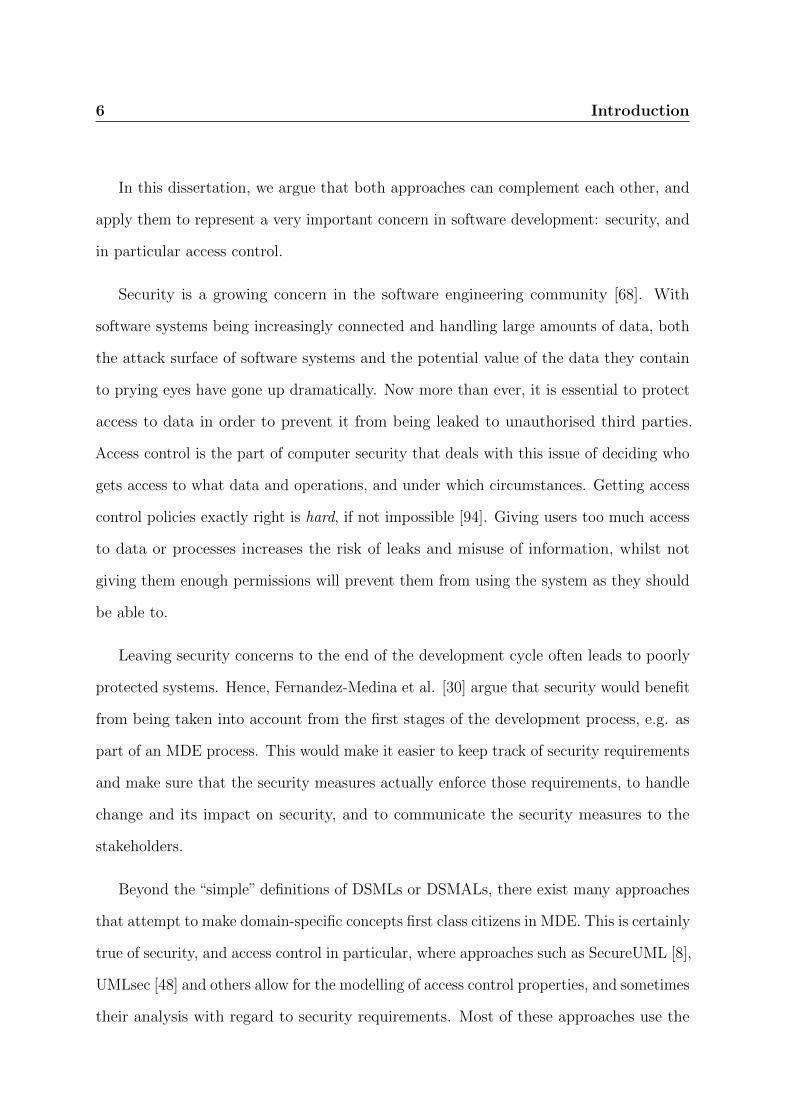
In this dissertation, we argue that both approaches can complement each other, and
apply them to represent a very important concern in software development: security, and
in particular access control.
Security is a growing concern in the software engineering community [68]. With
software systems being increasingly connected and handling large amounts of data, both
the attack surface of software systems and the potential value of the data they contain
to prying eyes have gone up dramatically. Now more than ever, it is essential to protect
access to data in order to prevent it from being leaked to unauthorised third parties.
Access control is the part of computer security that deals with this issue of deciding who
gets access to what data and operations, and under which circumstances. Getting access
control policies exactly right is hard, if not impossible [94]. Giving users too much access
to data or processes increases the risk of leaks and misuse of information, whilst not
giving them enough permissions will prevent them from using the system as they should
be able to.
Leaving security concerns to the end of the development cycle often leads to poorly
protected systems. Hence, Fernandez-Medina et al. [30] argue that security would benefit
from being taken into account from the first stages of the development process, e.g. as
part of an MDE process. This would make it easier to keep track of security requirements
and make sure that the security measures actually enforce those requirements, to handle
change and its impact on security, and to communicate the security measures to the
stakeholders.
Beyond the “simple” definitions of DSMLs or DSMALs, there exist many approaches
that attempt to make domain-specific concepts first class citizens in MDE. This is certainly
true of security, and access control in particular, where approaches such as SecureUML [8],
UMLsec [48] and others allow for the modelling of access control properties, and sometimes
their analysis with regard to security requirements. Most of these approaches use the

Introduction 7
role-based access control (RBAC) model, in which users are not directly given permissions.
Instead, they are assigned roles, and roles are assigned permissions.
While these approaches do allow one to take RBAC concerns into account early in the
development cycle, they still suffer some limitations. Some of them do not support the
entire RBAC standard, although others may support it entirely, and even support further
constructs that are not available in the standard. These approaches also often require
users to write queries themselves, or to interpret complex outputs, which could make
adoption by users with little technical background more difficult. Finally, while these
approaches are good at identifying errors in RBAC models, they do not help users in
fixing those errors, which can be a difficult and time-consuming process if done manually.
1.2. Research Objectives
The purpose of this dissertation is to explore and propose an approach for the modelling,
evaluation, analysis and fixing of domain-specific models, using both a DSML and a
DSMAL. The focus will be on the design compliance to RBAC, a widely-used and
standardised access control model. We will be looking at the following research question:
How can we design, analyse and fix RBAC concepts as part of an MDE process, in a
way that does not require users to write complex queries or code themselves, and using
(almost) exclusively OMG standards?
In particular, we will explore three MDE-related activities:
Modelling Perhaps the most important activity is the ability to model RBAC-specific
concerns;
Model analysis The ability to analyse the models against user-defined requirements
expressed as a form of tests that we call scenarios, and to perform further analysis

8 Introduction
on the model for well-formedness, scenario coverage, model completeness, scenario
satisfiability, and the identification of redundancies;
Fixing incorrect models When the evaluation of the models exposes errors, correcting
them can be very difficult to do manually: fixing an error in one place may raise
new errors, creating a long and error-prone cycle of error fixing. Therefore, an
automated discovery of possible solutions to an erroneous model may be of great
help to the stakeholders.
Because it is arguably the most widely known modelling language, and because of
its extension mechanism called profiles and the availability of UML modelling tools and
platforms, we selected UML to develop our approach. Bran Selic’s methodology for DSML
development [95] can be used not only to develop DSMLs, but also DSMALs, which is
why it has been selected for the development of both languages. Selic’s methodology
proposes a systematic way of developing a UML profile to implement a DSML, from a
model of the domain-specific concepts to be represented. The choice to develop both a
DSML and a DSMAL was made because each of them is better suited for some activities.
Many stakeholders are likely to use models produced as part of an MDE approach:
developers of course, as well as model designers, but also customers and other stakeholders,
who may not all have experience and knowledge in software engineering. Similarly, in
the case of domain-specific models, not all the stakeholders are necessarily au fait with
the specifics of the particular domain being studied. This is especially true of security,
which is a notoriously hard domain. It is therefore crucial for the proposed approach to
be accessible to non-experts. In particular, users should not be required to write any
code or queries themselves. Instead, the analysis of models should be automated, and
the queries and code should be hidden from the users.
This dissertation proposes four contributions:
Introduction 9
Modelling and analysing RBAC concerns using two UML profiles;
A classification of OCL constraints and the use of said classification to define a partial
order between the categories, to improve the evaluation speed and the user feedback
by only evaluating constraints if preconditions are satisfied;
The automated generation of fixes that can lead an incorrect model into a correct
state;
Two performance evaluations, one of the efficiency of the evaluation strategies pro-
posed, and one of the automated generation of model fixes.
We present rbacUML, an approach for modelling and analysing RBAC properties and
requirements on UML models. At the core of rbacUML are two UML profiles (rbacUML
and rbacDSML) that extend the UML meta-model. The focus is on using standard UML
technologies that designers may already know, in order to make the rbacUML approach
as easy to use as possible. Whilst the rbacUML profile defines a DSMAL, the rbacDSML
profile defines a DSML, both to express the access control properties and requirements.
Requirements can be expressed in the following forms:
scenarios specific actions that a particular user, given a set of active roles, must be able
to perform;
anti-scenarios specific actions that a particular user, given a set of active roles, cannot
perform.
Both profiles are made of three parts:
The configuration defines domain concepts (users, role hierarchies, etc.);
The policy identifies protected resources and defines their access requirements;

10 Introduction
The scenarios and anti-scenarios ensure that the model enforces the expected access
control requirements.
The first two follow traditional access control specifications, while the last one is required
solely for testing and verification purposes.
To address the“breadth of evaluation” issue, rbacUML provides the following evaluation
capabilities:
well-formedness Are there any syntactic or type errors in the model?
verification Are the scenarios and anti-scenarios enforced by the model?
completeness Is there anything missing in the model, e.g. are there users that have
been assigned no roles, or permissions that are not associated with any role?
coverage Which parts of the model are covered by access control (anti-) scenarios?
satisfiability Are some resources impossible to access, or some scenarios impossible to
complete, no matter which user carries them out?
redundancy Are there access control elements that are redundant, and could safely be
merged?
All the above analyses are implemented using OCL queries, the OMG’s standard
language for model queries. The last four allow users to identify “model smells”, areas
where the model may require some attention, but that are not necessarily errors.
As models grow, so does the number of OCL queries to evaluate, therefore increasing
the evaluation time. Moreover, the result of the evaluation of some constraints may
not always be useful to the designers. Moreover, lots of feedback can be given to the
designers, which may be confusing. By introducing a categorisation of OCL queries, and
by providing a partial order between the different categories, the proposed strategies will

Introduction 11
not only increase the verification speed by only evaluating the constraints required, but
also reduce the amount of unwanted feedback given to the designers.
In order to fix erroneous models in a way that is useful to stakeholders, two properties
need to be guaranteed:
Correctness Any solution generated must produce a correct model;
Completeness All possible solutions must be proposed, for the stakeholders to be able
to choose the most appropriate solution.
The performance of the rbacUML models analysis is evaluated, as well as the perfor-
mance of the time reduction strategies proposed. The different fixing strategies proposed
are also evaluated and compared.
1.3. Organisation of this Dissertation
This dissertation comprises 6 chapters. The first one is this introduction. Chapter 2
provides background and a review of the existing literature appropriate for this work.
Chapter 3 presents, discusses and compares the rbacUML DSMAL and the rbacDSML
DSML. rbacDSML is used in Chapter 4 to propose a solution to fix incorrect models.
Chapter 5 then presents the implementation of rbacUML and rbacDSML, and evaluates
the performance of the proposed model analysis and fixing approach. Chapter 6 suggests
future work and ends with concluding remarks.
As stated earlier in the declaration, some of the material in this dissertation has been
published in peer-reviewed venues. Material from our tool paper [64] can be found in
Chapter 5; material from our paper on challenges in model-based evolution and merging
of access control policies [63] is available in Chapters 2 and 6; material from our paper
on the representation of domain-specific concerns in MDE [66] is in Chapters 3 and 6;

12 Introduction
material from our paper on plug-in development on modelling platforms [65] is found in
Chapter 5.

Chapter 2.
Literature Review
13

14 Literature Review
This chapter reviews the literature relevant to this dissertation in three sections. The
first section introduces the concepts of model-driven engineering (MDE). The second
section is focused on access control, and how access control models evolved over time.
It also discusses the latest advances in the evaluation of access control policies. Finally,
the third section unites both areas by discussing existing approaches that attempt to
integrate access control concerns into MDE approaches. The strengths and weaknesses
of these approaches are discussed, highlighting the gap that this dissertation attempts to
fill.
2.1. Model-Driven Engineering
The use of models to reduce software complexity has been advocated for decades in the
software engineering community [93]. The OMG, for example, proposes a four-layer
architecture [13], summarised in Table 2.1. The lowest level (M0), at the bottom of the
table, is an instance of a model, i.e. the real system. The next level (M1) is the model level,
which conforms to a meta-model on level M2, itself conforming to the meta-meta-model
on the highest level (M3) [13]. According to Bezivin, a model conforms to a meta-model
“if and only if each model element has its metaelement defined in the metamodel” [14].
In the same manner, a meta-model conforms to a meta-meta-model if and only if each
meta-model element has its meta-element defined in the meta-meta-model.
Table 2.1.: Table of the OMG organisation in a four-level architecture
Level Name Description
M3 Meta-meta-model describes meta-models
M2 Meta-model describes the elements of a model, conforms to M3
M1 Model describes a system, conforms to M2
M0 Instance describes an instance of the model, conforms to M1

Literature Review 15
Several organisations and companies have proposed platforms to support MDE, such
as Microsoft’s Software Factories [37] or OMG’s MDA [102]. The focus of this dissertation
will be on OMG’s set of standards, which includes the widely known Unified Modelling
Language (UML).
In this dissertation, we focus on the design level. The argument made by Ferandez-
Medina et al. [30] is that, since design often comes before implementation, at least in
traditional development models such as the waterfall or the V model, a way of taking
security into account early in the software development cycle is to express it at the design
level. Furthermore, the design level already provides sufficient detail (e.g. the resources
that need to be protected) to reason about access control, making it a sensible choice
for early analysis. In some software engineering practices, the design level comes after
the elicitation of requirements. Therefore, we assume that the specific access control
requirements to be enforced have already been defined. While expressing and verifying
access control requirements could perhaps already be done at that level, it is out of the
scope of our approach. Such a solution would not replace our approach, but complement
it. First, because the design level contains more details than the requirements level.
Second, because while security should be taken into account as early as possible [30],
traceability of security concerns throughout all the phases of the software development
process is also essential.
The proposed approach is clearly solution-oriented, and assumes that the solution to
a real world problem has been defined. The focus is on how to gain confidence in the
fact that the software actually enforces that solution, i.e. conforms to the access control
requirements, not how the solution has been found or whether or not it actually solves
the real world problem.

16 Literature Review
2.1.1. MDE using OMG Standards
The Object Management Group (OMG) [74] is a not-for-profit consortium that “develops
enterprise integration standards for a wide range of technologies”. In 2001, the OMG
launched its own initiative to support model-driven engineering: Model-Driven Architec-
ture (MDA) [102]. MDA is “the realisation of model engineering principles around a set
of OMG standards” [13]. Such standards include the Unified Modeling Language (UML),
the Object Constraint Language (OCL), and the Meta-Object Framework (MOF).
MDA introduces a key distinction between platform-independent models (PIM) and
platform-specific models (PSM). The former are the higher-level representations of a
software system, which are meant to be later specialised into PSMs as the choice of
platform is made. The OMG defines PIM as “a formal specification of the structure and
function of a system that abstracts away technical detail”, while PSM is defined as “a
specification model of the target platform”. It is an intermediate step between the PIM
and the implementation. This distinction has been introduced as the OMG was facing a
rise in the number of frameworks and middlewares that their members were using. By
specifying PIM models, one could describe a system without taking its implementation
into account, leaving the PSM details for when the target platform was chosen. This
allows one to easily change the platform as well, without affecting the PIM at all.
Steve Cook retraces the history of UML and states that it finds its roots in the
development of object-oriented languages, as well as the graphical design languages
of the early 1990s [22]. In 1994, a study commissioned by the OMG concluded that
standardisation of these languages was required. A consultation process was then
engaged, that led to a submission by Rational Software Corporation of the Unified
Modeling Language 1.0. The first specification published by OMG was UML 1.1 [77], the
result of a compromise over the several submissions to the consultation. In particular,
OCL was integrated into the publication, but actually came from IBM/ObjectTime’s

Literature Review 17
Table 2.2.: The 4-layer structure of the UML architecture [55]
Level Name Content
M3 meta-meta-model MOF meta-meta-model
M2 meta-model UML meta-model
M1 model UML analysis model (e.g. class diagrams)
M0 instance UML instance model (e.g. object diagrams)
submission [112]. At the time, UML 1.1 supported 8 types of diagrams. Several
refinements of UML were later published, until UML 1.4 in 2001 [78]. UML quickly
became the most prominent modelling language in industry and academia [22]. A bigger
overhaul of the UML standard was published in 2005, called UML 2.0 [79]. UML 2
was meant to address the issues of UML 1.x that had been raised by practitioners and
academics. In particular, MOF [73] was introduced as “a modelling language for specifying
meta-models”, and used to formally define UML 2. UML loosely followed the 4-layers
architecture from Table 2.1, as pointed out by Kobryn [55] and summarised in Table 2.2.
The UML 2.x revision process continues to this day.
One important feature of UML is profiles [21]. Whilst UML is a general-purpose
language, it can be extended with new constructs using the profile mechanism, which
is essentially an extension of the UML meta-model using stereotypes and stereotype
attributes, also called tagged values. UML profiles allow one to define domain-specific
constructs to use with UML models. The OMG has released a few standardised UML
profiles, such as the System Modeling Language (SysML) [80], or the profile for Modeling
and Analysis of Real-time Embedded Systems (MARTE) [81].
UML 2.3 [76], the latest release, has 14 types of diagrams, divided largely into two
categories: structural diagrams and behavioural diagrams. There is also a sub-category
of behavioural diagrams called interaction diagrams:
• Structural diagrams

18 Literature Review
– Profile diagrams
– Class diagrams
– Composite structure diagrams
– Component diagrams
– Deployment diagrams
– Object diagrams
– Package diagrams
• Behavioural diagrams
– Activity diagrams
– Use case diagrams
– State machine diagrams
– Interaction diagrams:
∗ Sequence diagrams
∗ Communication diagrams
∗ Interaction Overview diagrams
∗ Timing diagram
2.1.2. Model Transformations as Graph Transformations
Mens et al. have proposed a taxonomy of model transformations [60], and applied
it to graph transformation tools [61]. This makes a lot of sense, since models are
typically very much graph-like: in UML, for example, model elements are nodes, and

Literature Review 19
associations between elements are edges between nodes. It therefore makes sense to treat
models as graphs, which allows one to apply graph theory principles and techniques
to analyse and transform models. The graph-based model transformation tools they
analysed are VIATRA [23], a model checking and verification tool; GReAT [104], a model
transformation tool; Fujaba [17], a re-engineering tool; and AGG [1], a general-purpose
graph transformation tool. The authors claim that their taxonomy is general enough to
apply to other graph transformation tools as well.
Bergmann et al. [12] have successfully used graph transformations for several purposes,
including live incremental transformations and model transformations by example. The
former is really useful in a situation where several models need to be kept in sync.
Instead of doing batch transformations to reflect changes from the source model to the
target models, live incremental transformations provide an efficient way of performing
the transformations continuously, by analysing the impact of each change to the model
elements, and identifying which target elements may potentially be affected by each
change. The latter allows one to semi-automatically define model transformations. The
analysis of a few example transformations provided by the user allow the engine to derive
possible transformation rules, that can then be applied to entire graphs.
2.1.3. Inconsistency Detection and Resolution
During the MDE development cycle, it is likely that inconsistencies between parts of the
models will occur. It is important to be able to detect those inconsistencies and resolve
them. One should note that the process of inconsistency handling is very similar to the
process of software merging, and therefore, some techniques developed for the former
have been used in the latter, and vice-versa. By inconsistencies, we specifically mean
contradictions, often between two different diagrams, in the same model. For example,
Figure 2.1 shows a class diagram as well as a sequence diagram. The sequence diagram

20 Literature Review
represents a call from an object of type A to an object of type B, using its operation
getAddress() that is not listed in the class diagram.
(a) Class diagram
(b) Sequence diagram
Figure 2.1.: A sample inconsistency between a sequence diagram and a class diagram
The first attempt at inconsistencies detection has been suggested by Finkelstein et al.
[33] with their ViewPoints framework that allows each actor to have its own view of the
system, consisting of only the diagrams that make sense to him/her.
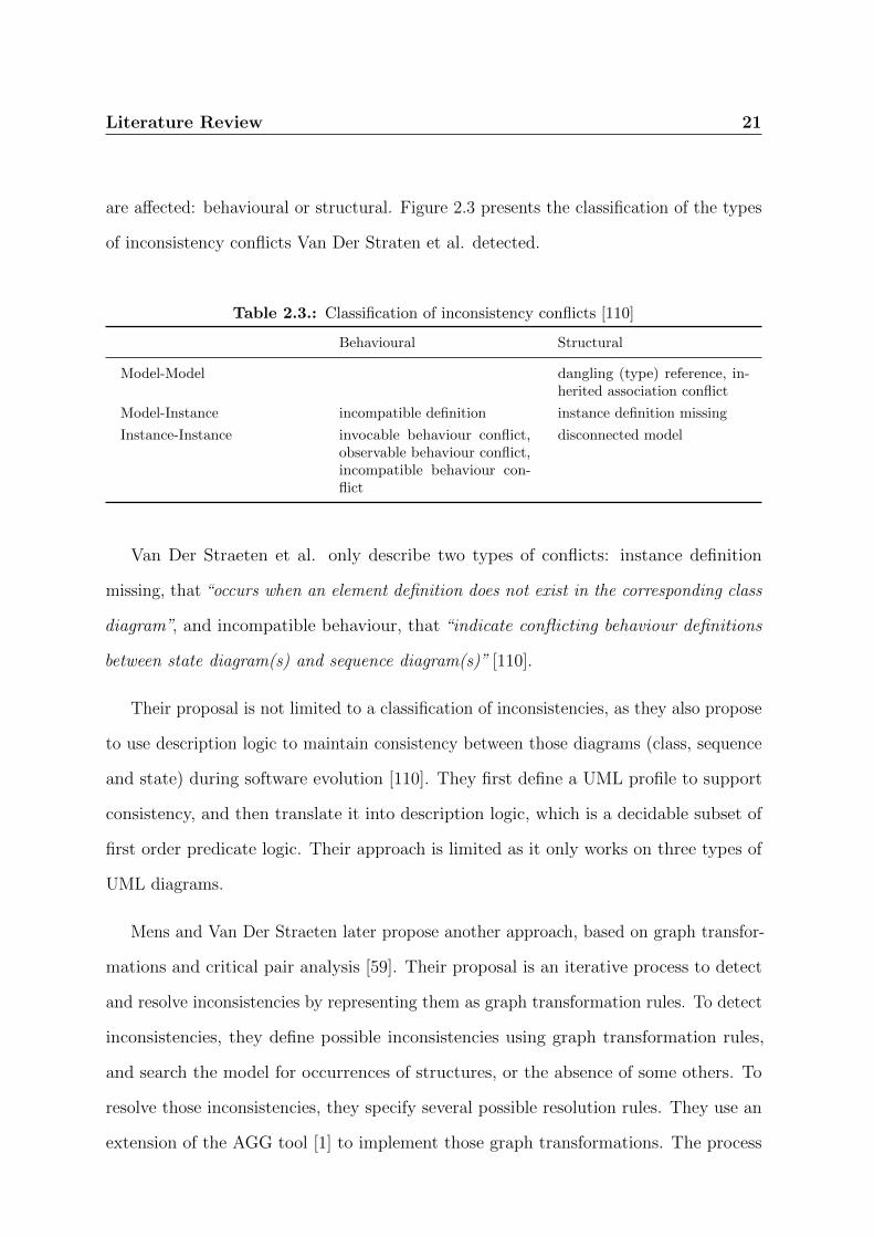
Van Der Straeten et al. propose a two dimensional classification of inconsistencies
[110] between class, sequence and state diagrams. The first dimension describes the
type of affected model, according to MDA as described in section 2.1.1. Conflicts can
arise between a model and a model, between a model and an instance, or between an
instance and an instance. The second dimension describes which aspects of the model
Literature Review 21
are affected: behavioural or structural. Figure 2.3 presents the classification of the types
of inconsistency conflicts Van Der Straten et al. detected.
Table 2.3.: Classification of inconsistency conflicts [110]
Behavioural Structural
Model-Model dangling (type) reference, in-herited association conflict
Model-Instance incompatible definition instance definition missing
Instance-Instance invocable behaviour conflict,observable behaviour conflict,incompatible behaviour con-flict
disconnected model
Van Der Straeten et al. only describe two types of conflicts: instance definition
missing, that “occurs when an element definition does not exist in the corresponding class
diagram”, and incompatible behaviour, that “indicate conflicting behaviour definitions
between state diagram(s) and sequence diagram(s)” [110].
Their proposal is not limited to a classification of inconsistencies, as they also propose
to use description logic to maintain consistency between those diagrams (class, sequence
and state) during software evolution [110]. They first define a UML profile to support
consistency, and then translate it into description logic, which is a decidable subset of
first order predicate logic. Their approach is limited as it only works on three types of
UML diagrams.
Mens and Van Der Straeten later propose another approach, based on graph transfor-
mations and critical pair analysis [59]. Their proposal is an iterative process to detect
and resolve inconsistencies by representing them as graph transformation rules. To detect
inconsistencies, they define possible inconsistencies using graph transformation rules,
and search the model for occurrences of structures, or the absence of some others. To
resolve those inconsistencies, they specify several possible resolution rules. They use an
extension of the AGG tool [1] to implement those graph transformations. The process

22 Literature Review
is incremental because resolving one inconsistency might lead to other inconsistencies
(induced inconsistencies), or because several resolution rules might interfere with each
other (conflicting resolutions). To avoid infinite iterations, they use critical pair analysis
to avoid cycles in the resolution process.
Yet another approach to detecting inconsistencies is proposed by Blanc et al., and
uses operation-based model construction [16], which “represents models by sequences
of elementary construction operations, rather than by the set of model elements they
contain” [16]. This approach has the advantage of being independent of any metamodel.
It is, therefore, not limited to some types of UML diagrams like the solutions discussed
earlier. It is inspired by the work of Lippe and Van Oosterom [57] in software merging
that proposed an operation-based approach to software merging. By defining only four
operations (create, delete, setProperty and setReference), one can build any model
conforming to any metamodel using a sequence of atomic operations. Blanc et al. consider
two kinds of consistency rules ([16]):
structural consistency rules define relationships that should hold between model ele-
ments regardless of how they have been constructed;
methodological consistency rules are constraints over the construction process itself.
Rules of both types are defined using predicate logic, and then checked using a Prolog
engine. While this is a sound and well understood solution, it has the drawback of
potentially leading to infinite loops. As opposed to Van Der Straeten et al. [110] who
chose to use a subset of first order logic to avoid infinite loops, Blanc et al. decided
to transfer the responsibility of ensuring that infinite loops will not happen to the
transformation rule developers.
Another drawback of Blanc’s approach is that the inconsistency checking process
has to be run as a batch job, while it would be desirable for the application developer
Literature Review 23
to get instant feedback while the model is built. They addressed this problem later
by providing an incremental detection approach that still uses operation-based model
construction [15]. By using an incremental checking strategy instead of checking the
whole model as a batch, the number of consistency rules to check is drastically reduced.
To do so, they use equivalence class partitioning to classify the rules, and select those
which are actually impacted by the changes that have been made. An impact matrix is
then constructed to point out which operations might impact inconsistency rules. Since
the inconsistency checking process is now much faster, it has been integrated into the
Eclipse GMF modelling environment, as well as Rational Software Architect.
Realising that, even though progress had been made in inconsistency detection, those
techniques were not really used by industry professionals, Egyed observed that the main
obstacle to wide adoption of inconsistency detection was feedback, which was too slow
and of poor quality [28]. To get useful feedback, professionals need it instantly and in a
useful way, i.e. they want to know which model elements are involved in an inconsistency
problem. To achieve instant and useful feedback, Egyed uses incremental consistency
checking. To find out what the impact of changes are on the model, he compares three
solutions: the “what happens if . . . ” approach, the type-based scope approach, and the
instance-based scope approach. The first one simply asks the question “What happens if
this element changes?” The problem is that each change in an element is likely to have
impact on a lot of other elements, and it is very hard to identify all possible impacted
elements. The type-based method uses the type of the modified element to find out
which other types of elements might be impacted. Finally, the instance-based method is
similar to the type-based method, but instead of working on element types, it works on
instances of those elements. The last method is the one chosen by Egyed in his approach.
Combined with a profiler that monitors the changes to the model, he can identify very
quickly which consistency rules need to be reevaluated after each change. His approach

24 Literature Review
has been tested on models involving tens-of-thousands of elements and consistency rules,
and it was shown to provide “instant” response even on the largest examples.
Later, Egyed et al. built on top of their inconsistency checking method a technique to
generate a set of concrete changes to fix those inconsistencies, and providing information
about each change’s impact on other consistency rules [29]. Instead of using fixing rules
that, together with the consistency rules, propose possible solutions, Egyed et al., after
generating all possible fixes, test them one after the other to determine which ones
are actually valid. A valid solution is a solution that actually solves the inconsistency,
without introducing a new one. Once again, empirical evidence has shown that, even on
very large models, the feedback to the user comes “instantly” [29].
Egyed’s approach has two limitations. First, it will only generate potential fixes that
do not involve the creation of new model elements. Second, it only supports fixes that
involve change in only one location.
It would be greatly beneficial to have such a technique for access control properties,
as changes in the model, or in the access control properties themselves could also lead to
inconsistencies, that could harm the efficiency of the access control model. Just as for
UML models in general, incremental detection of inconsistencies would offer professionals
a much faster and therefore more interesting feedback on the consequences of their
changes in terms of access control.
2.2. Access Control
Access control is an old problem, that probably appeared with the development of
multi-user operating systems. Concerns have quickly grown over who should be able to
access, create or modify resources and data. It became apparent that access to data
and processes had to be restricted. In 1985, the US Department of Defense released

Literature Review 25
the Trusted Computer System Evaluation Criteria (TCSEC) [54], defining two models
for access control: Discretionary Access Control (DAC) and Mandatory Access Control
(MAC). They are still used today, but have shown their limits, and since then, new
models of access control, such as Role-Based Access Control (RBAC) or the more recent
Attribute-Based Access Control (ABAC) have been developed to address those limits.
This section first highlights the distinction between authentication and authorisation,
and then discusses the most important authorisation models.
2.2.1. Authentication and Authorisation
Access control is a term that encompasses two complementary yet rather different concepts:
authentication and authorisation. The US Committee on National Security Systems
(CNSS), in its National Information Assurance Glossary [20], defines authentication as
follows:
Definition 1. Authentication. The process of verifying the identity or other attributes
claimed by or assumed of an entity (user, process, or device), or to verify the source and
integrity of data.
It also defines authorisation as follows:
Definition 2. Authorisation. Access privileges granted to a user, program, or process
or the act of granting those privileges.
Another way of looking at those two concepts is that authentication is the process of
making sure that the user is actually who (or the device is actually what) they claim to
be, and authorisation is the process that determines whether or not a user (or device)
has the access to a resource.

26 Literature Review
This thesis only discusses authorisation. The models presented are indeed only
concerned with authorisation, even though their name may suggest that they also touch
on authentication issues.
2.2.2. Discretionary Access Control
Discretionary Access Control is one of the access control models defined in 1985 by the
TCSEC [54] as “a means of restricting access to objects based on the identity of subjects
and/or groups to which they belong. The controls are discretionary in the sense that a
subject with a certain access permission is capable of passing that permission (perhaps
indirectly) on to any other subject (unless restrained by mandatory access control)”.
A well known example of DAC is the permission system in UNIX systems, which
defines read, write and execute permissions on every file, for its owner, its group and
all the other users.
2.2.3. Mandatory Access Control
Mandatory Access Control is the other access control model defined by the TCSEC. The
TCSEC defines MAC as “a means of restricting access to objects based on the sensitivity
(as represented by a label) of the information contained in the objects and the formal
authorisation (i.e., clearance) of subjects to access information of such sensitivity” [54].
Compared to DAC, MAC is more expressive as it allows the administrator to limit the
objects owner’s ability to perform some operations. For example, an administrator might
want to forbid a range of users from making their files executable.
Multi-Level Security (MLS) [11] can also be achieved with MAC. MLS allows one to
define several clearance levels. Each object would get a security level, and only users
having a clearance level equal or higher to the object’s security level would be able to
Literature Review 27
perform read operations on said objects, whilst only users having a clearance level lower
or equal to the object’s security level would be able to perform write operations on said
objects.
2.2.4. Role-Based Access Control
Role-Based Access Control (RBAC) differs from MAC and DAC as it does not directly
assign permissions to users. Instead, it introduces the concept of roles. Roles are
assigned a set of permissions, and each role can be assigned to as many users as necessary.
Permissions in RBAC cannot be assigned to users directly. RBAC was first formalised
as a general-purpose access control model by Ferraiolo and Kuhn [32], and then refined
by Ferraiolo et al. [31]. Later, Sandhu et al. proposed a decomposition of RBAC into
4 different levels, each one adding new features on top of the previous one [92]. The
authors then combined their efforts to produce a NIST standard proposal [91], that has
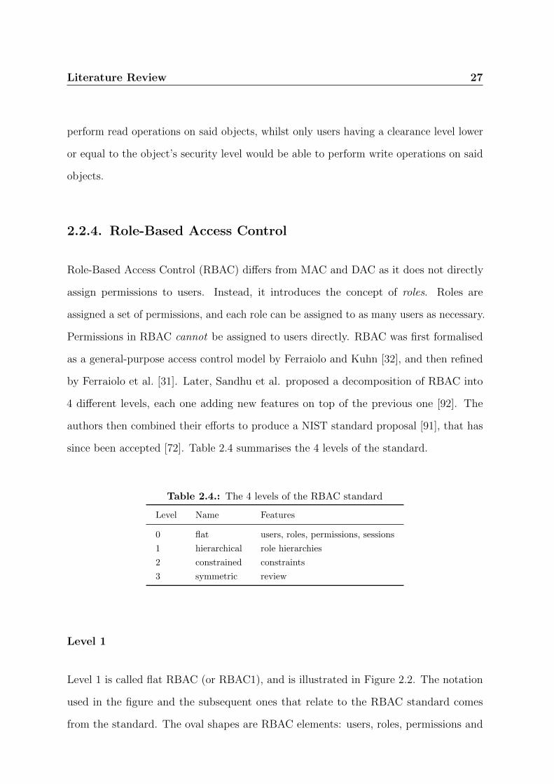
since been accepted [72]. Table 2.4 summarises the 4 levels of the standard.
Table 2.4.: The 4 levels of the RBAC standard
Level Name Features
0 flat users, roles, permissions, sessions
1 hierarchical role hierarchies
2 constrained constraints
3 symmetric review
Level 1
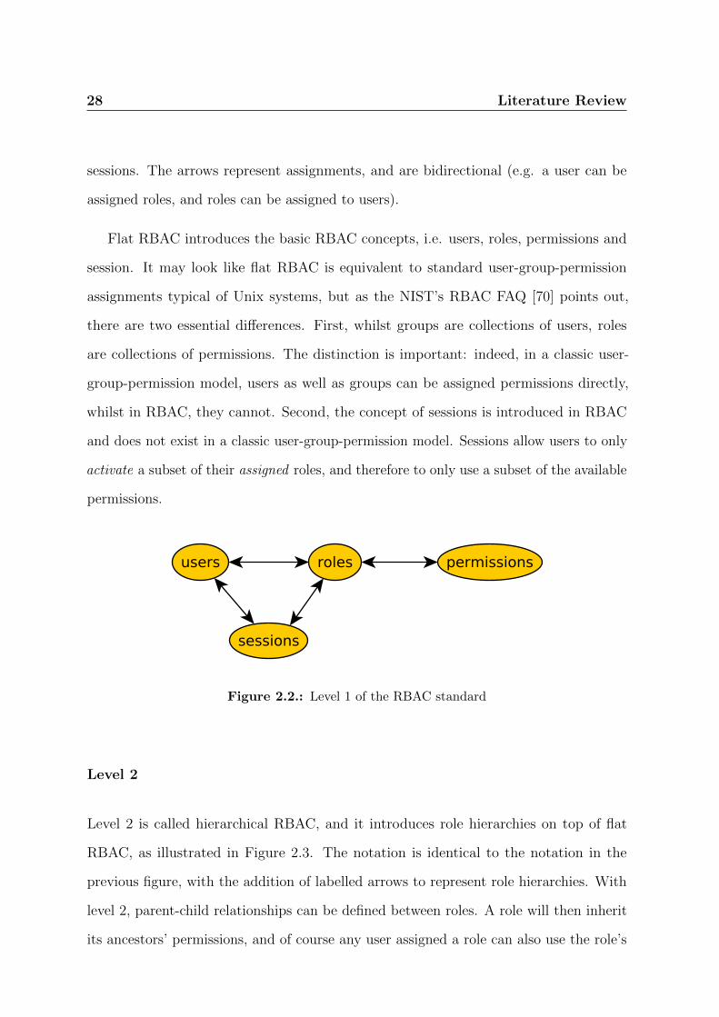
Level 1 is called flat RBAC (or RBAC1), and is illustrated in Figure 2.2. The notation
used in the figure and the subsequent ones that relate to the RBAC standard comes
from the standard. The oval shapes are RBAC elements: users, roles, permissions and
28 Literature Review
sessions. The arrows represent assignments, and are bidirectional (e.g. a user can be
assigned roles, and roles can be assigned to users).
Flat RBAC introduces the basic RBAC concepts, i.e. users, roles, permissions and
session. It may look like flat RBAC is equivalent to standard user-group-permission
assignments typical of Unix systems, but as the NIST’s RBAC FAQ [70] points out,
there are two essential differences. First, whilst groups are collections of users, roles
are collections of permissions. The distinction is important: indeed, in a classic user-
group-permission model, users as well as groups can be assigned permissions directly,
whilst in RBAC, they cannot. Second, the concept of sessions is introduced in RBAC
and does not exist in a classic user-group-permission model. Sessions allow users to only
activate a subset of their assigned roles, and therefore to only use a subset of the available
permissions.
Figure 2.2.: Level 1 of the RBAC standard
Level 2
Level 2 is called hierarchical RBAC, and it introduces role hierarchies on top of flat
RBAC, as illustrated in Figure 2.3. The notation is identical to the notation in the
previous figure, with the addition of labelled arrows to represent role hierarchies. With
level 2, parent-child relationships can be defined between roles. A role will then inherit
its ancestors’ permissions, and of course any user assigned a role can also use the role’s

Literature Review 29
ancestors’ permissions. Level 2 is actually divided in two sub-levels that are carried on
in the next levels: level 2a allows for arbitrary hierarchies between roles, whilst level 2b
only supports limited hierarchies. What “limited” actually means is not specified by the
standard, and it is left to product vendors to specify which limitations are built into their
product.
Figure 2.3.: Level 2 of the RBAC standard
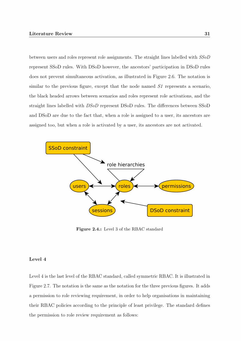
Level 3
Level 3 is called constrained RBAC, as illustrated in Figure 2.4. Once again, the notation
is identical to the notation in the previous two figures, with the addition of constraints,
represented by rectangles, and their application, represented by arrows. Level 3 adds on
top of level 2 the ability to express and enforce separation of duty (SoD) constraints. The
standard’s understanding of separation of duty is closest to Ferraiolo et al.’s work [31],
and includes two types of constraints: static separation of duty (SSoD) and dynamic
separation of duty (DSoD).
A separation of duty constraint, whether static or dynamic, is a relationship between
two roles whose aim is to make sure that users will never be able to acquire too much
power through the combination of the permissions assigned to each of those two roles.

30 Literature Review
Static separation of duty constraints impose rules on user-role assignments. If there
is an SSoD rule involving roles A and B, then users cannot be assigned A and B. They
can be assigned A and not B, or B and not A, or neither A nor B. Formally, SSoD can
be expressed as follows:
∀u : user, ri,j : roles : i 6= j :
u ∈ roleMembers(ri) ∧ u ∈ roleMembers(rj)⇒ ri 6∈ ssod(rj)
where roleMembers(ri) denotes the set of users that have been assigned the role ri, and
where ssod(rj) denotes the set of roles that participate in an SSoD rule with rj [31].
Dynamic separation of duty constraints are a bit more relaxed, as they do not impose
any restriction on role assignments, but only on their activation. Indeed, if there is a
DSoD rule involving roles A and B, then users can be assigned both A and B, but they
cannot activate them together. This will prevent users from using the permissions from
both A and B at the same time. Formally, DSoD can be expressed as follows:
∀s : subject, ri,j : roles : i 6= j :
ri ∈ activeRoles(s) ∧ rj ∈ activeRoles(s)⇒ ri 6∈ dsod(rj)
where s denotes a subject, i.e. the state of a user at a particular point during a session,
where activeRoles(s) denotes the set of roles activated by s, and where dsod(rj) denotes
the set of roles that particitate in an DSoD rule with rj [31].
The two types of SoD constraint behave differently in the presence of role hierarchies.
With SSoD, two roles cannot be assigned to the same user if two of their ancestors
participate in a SSoD rule, as illustrated in Figure 2.5. In the figure, each node whose
name starts with R represents a role, whilst the nodes named U1 represent a user. The
white headed arrows between roles represent role hierarchies, and the black headed arrows
Literature Review 31
between users and roles represent role assignments. The straight lines labelled with SSoD
represent SSoD rules. With DSoD however, the ancestors’ participation in DSoD rules
does not prevent simultaneous activation, as illustrated in Figure 2.6. The notation is
similar to the previous figure, except that the node named S1 represents a scenario,
the black headed arrows between scenarios and roles represent role activations, and the
straight lines labelled with DSoD represent DSoD rules. The differences between SSoD
and DSoD are due to the fact that, when a role is assigned to a user, its ancestors are
assigned too, but when a role is activated by a user, its ancestors are not activated.
Figure 2.4.: Level 3 of the RBAC standard
Level 4
Level 4 is the last level of the RBAC standard, called symmetric RBAC. It is illustrated in
Figure 2.7. The notation is the same as the notation for the three previous figures. It adds
a permission to role reviewing requirement, in order to help organisations in maintaining
their RBAC policies according to the principle of least privilege. The standard defines
the permission to role review requirement as follows:

32 Literature Review
(a) SSoD violation (b) SSoD violation (c) SSoD violation
Figure 2.5.: SSoD and role hierarchies
(a) DSoD: no violation (b) DSoD: no violation (c) DSoD: no violation
Figure 2.6.: DSoD and role hierarchies

Literature Review 33
Definition 3. To effectively maintain permission assignments an organization must be
provided with the ability to identify and review the assignments of permissions to roles
regardless of where they might reside in the organization. When maintaining permission
assignments, special attention is taken to abide by the principle of least privilege. [91]1
The principle of least privilege mandates that every program and every user should
operate using the least set of privileges required to complete their job [89].
The motivation behind this level of RBAC is to allow system administrators to easily
review which roles, and therefore which users, have a specific permission. This can be
helpful when dealing with access control policies that have complex role hierarchies. The
level 4 requirements allow system administrator to be satisfied that their policy actually
behaves as they expect by verifying that a particular user is indeed granted a particular
permission.
Figure 2.7.: Level 4 of the RBAC standard
1This quote is reproduced here in its original American English spelling

34 Literature Review
Limitations of RBAC
RBAC is a model for access control configurations that only rely on roles. It is possible
to “bend” the roles in RBAC to represent other concepts, such as time. For example, an
organisation may only give some permissions during working hours. It can be represented
in RBAC by creating new roles for operations that can only be carried on during working
hours. Similarly, one can introduce other attributes such as the user’s location or the
type of connection to the system (i.e. company LAN, internet, VPN, etc.). The problem
with this approach is that it quickly increases the number of roles, making them more
difficult to manage effectively. Two types of solutions have been proposed to address
these shortcomings: extensions of RBAC, and attribute-based access control.
2.2.5. Extensions to RBAC
Many extensions of RBAC have been proposed over the years, some of which even before
the RBAC standard was finalised. In this section, we briefly describe two of them, to
illustrate the extensibility of the RBAC model, and how it has been used as the basis for
more expressive models.
Organisation-based Access Control
Organisation-based Access Control (OrBAC) was proposed in 2003 by Kalam et al. [51]
in order to overcome some of the limitations of RBAC, by considering organisations
together with context. The most important entity is the organisation, and it can be
seen as “an organised group of active entities, i.e. subjects, playing some role or other”.
OrBAC also defines other concepts, such as: objects, which are inactive entities; views,
which are “sets of objects that satisfy a common property”; actions like read, write,
update, etc; and activities, which abstract actions in the same way as views abstract
Literature Review 35
objects and roles abstract subjects. Finally, contexts are circumstances under which
certain permissions will be granted.
Security policies in OrBAC allow one to define permissions, obligations, prohibitions
and recommendations. To our knowledge, there is not a standardised definition of
OrBAC.
GEO-RBAC
GEO-RBAC is an extension of the RBAC standard that adds location information to
the RBAC standard [24]. Both users and resources can be given a location. The user’s
location will affect the roles he can activate, while the resource’s location will affect
the permissions that are required to access it. Interestingly, GEO-RBAC follows the
RBAC standard’s four-level structure, adding new constructs as required to support their
location-aware extension of RBAC. SoD constraints are also extended to allow for the
definition of spatial conditions.
2.2.6. Attribute-Based Access Control
Attribute-Based Access Control (ABAC) refers to a family of access control models
that are inspired by RBAC but more flexible. As Sandhu points out, there is no single,
standardised ABAC model [90], but instead several proposals, such as Park and Sandhu’s
UNCONABC [82] or Wang et al’s logic-based ABAC framework [111].
Where RBAC defines roles between users and permissions, ABAC defines attributes,
that can be required or forbidden in order to give users access to resources. Attributes
could be roles of course, but also time, location, or any other criteria used to decide
whether or not access to resources should be granted. Typically, an access control rule will
specify a series of attributes and their required values to allow for a particular resource
36 Literature Review
to be accessed. For example, an ABAC rule could state that all bank clerks can read
customers’ balance from the branch they work at, between 9am and 4pm on weekdays, and
between 9am and 1pm on Saturdays. The attributes are a role (bank clerks), a location
(the branch where the user works), and a time (between 9am and 4pm on weekdays,
between 9am and 1pm on Saturdays). The resource whose access is protected is the
customers’ balance, in read mode. Any user that satisfies the rule will be granted access
by the ABAC system, and any user that does not satisfy the rule will be refused access
by the ABAC system.
XACML
XACML stands for eXtensible Access Control Markup Language[71], a standard for
ABAC policies, in XML. Its third version has been standardised by OASIS in January
2013 [71].
2.2.7. Access Control Properties Analysis
A lot of research has also been conducted on verifying the conformance of access control
policies to some properties or requirements, often using XACML. Fisler et al. propose to
transform XACML policies into decision-diagrams to answer queries about said policies,
and support evolution of those policies through semantic differencing [34]. Hughes and
Bultan take a different approach, as they use a SAT solver to verify properties on XACML
policies [45]. Their work is not limited to RBAC, but applies to any policy defined using
XACML. Gofman et al. propose RBAC-PAT [36], a tool for analysing RBAC and
ARBAC policies. ARBAC is an extension of RBAC that allows one to specify what
parts of the policy each administrator is allowed to change. This leads to potentially
complex questions about the effects of changes by the administrators. Extending ARBAC

Literature Review 37
further, Stoller et al. propose Parameterised ARBAC (PARBAC) [106], which supports
parameters in order to improve the scalability and applicability of ARBAC policies,
and propose an analysis algorithm for PARBAC policies. Dougherty et al. [26] define a
framework for reasoning about dynamic access control policies, while focusing on goal
reachability and contextual policy containment.
Another access control framework was built around Ponder, a policy specification
language developed at Imperial College in London [25]. Ponder2 is its current version,
a complete re-write of the Ponder language and its associated framework. The name
“Ponder2”, just like “Ponder”, is used to refer to both the language and the framework
built around it [109]. Ponder2 allows one to define access control policies according to
an ABAC model. Both obligation policies and authorisation policies can be expressed,
as well as constraints on role assignments. Obligation policies are expressed in an
Event-Condition-Action manner, to specify the system’s response to events under certain
conditions. Authorisation policies are defined to specify what a subject can or cannot do
on a particular target [25]. Ponder2 is a very complete framework that provides a lot of
analysis capabilities such as resolving conflicts in policies [88]. It uses event calculus to
formalise and analyse the policy specifications [6].
The approaches described in this section, and the tools that implement them, all work
on the artefact level (M0 in the OMG architecture decomposition), while the approach
we propose focuses on the model level (M1 in the OMG architecture decomposition).
Generally, the approaches described in this section focus on the ability to evaluate various
aspects of access control policies, and to verify any property that can be expressed using
the language provided. This often means that users need to write queries on the policy,
or constraints that the policy should satisfy.
The approach we propose in this dissertation differs not only by the level (M1) at
which we operate, but also by the way our users analyse their models. We want to let

38 Literature Review
them express requirements without having to write constraints or queries themselves,
unless they explicitely want to. The consequence is that we have written the constraints
ourselves, which necessarily limits the number of constraints that can be evaluated. In
other words, we have decided to compromise on the expressiveness in order to lower the
technical knowledge requirements, and to tightly integrate our approach with MDE.
2.3. Access Control and MDE
Many approaches have been proposed for representing RBAC as part of a Model-Driven
Engineering approach.
2.3.1. Shin and Ahn’s RBAC Representation
Perhaps the first solution for representing RBAC concerns on UML models is Shin and
Ahn’s representation [97], whose purpose was to reduce the gap between security models
and system developments. They define three views for representing RBAC models: the
static view, using class diagrams, to represent users, roles, permissions and sessions, and
to define their assignments and hierarchies; the functional view, using use case diagrams,
to represent functions that the RBAC model should enforce; the dynamic view, that
refines the functional view by making the interactions between objects explicit.
On top of this extension of the UML meta-model, they define several access control
constraints expressed using OCL, such as separation of duty, prerequisite and cardinality
constraints [5]. These constraints are model-specific, as they include, for example, the
sets of users participating in separation of duty constraints. Therefore, they need to be
adapted by the designer to each particular model.
Literature Review 39
2.3.2. UMLsec
UMLsec [48] is an extension of UML 1.4 designed to allow one to express security
properties, annotate a UML design, and check the annotated design against said properties.
UMLsec uses the standard UML extension mechanisms: stereotypes and tagged values,
and provides a tool implementation [3]. Whilst it is not limited to RBAC or even access
control, it includes an RBAC profile [48, 62] allowing one to model and verify RBAC
concepts on an activity diagram only. Furthermore, UMLsec provides a mechanism that
allows one to represent attacker profiles (profile here means the capabilities of an attacker,
not the UML extension mechanism), but as far as we know, this has not been implemented
for the RBAC part of UMLsec, specifically. UMLsec’s use of UML 1.x tagged values
makes it difficult to use with large models, as all assignments are represented using tuples
in a list. Whilst the RBAC profile only covers the first 2 levels of the RBAC standard,
related work by Hohn and Jurjens [43] uses Prolog to verify authorisation rules against
business requirements, including separation of duty constraints. Their tool supports
the SAP system, and can be extended to support other software as well [44]. Another
component of UMLsec is related to access control: the analysis of permissions delegations,
using class and sequence diagrams [49]. This is however out of the scope of the RBAC
standard.
2.3.3. SecureUML
Basin et al’s research in Model-Driven Security (MDS) [8] has touched on many compo-
nents of MDE, such as modelling, analysis, model transformation and code generation.
The focus here is on the first two aspects. SecureUML [58, 10, 7] is their illustration of
MDS. It is a security modelling language that can be combined with a system design mod-
elling language such as ComponentUML [58], ControllerUML [10, 8] or ActionGUI [9, 8],
40 Literature Review
using a dialect that glues the two languages together, allowing SecureUML to add ac-
cess control annotations to the system design modelling language. As a consequence,
SecureUML can be applied to a large set of models.
The constraints definition and the analysis in SecureUML are interesting: indeed,
SecureUML supports analysis through OCL constraints written by the designers, at
the model level. With the help of a few handy helper functions, designers can define a
large set of authorisation constraints, that go beyond the RBAC standard. They can
also write model-level OCL constraints to query the model, therefore providing analysis
features only limited by the designer’s imagination and technical abilities. However, an
OCL constraint is not affected by the existence of another OCL constraint on the model.
Therefore, if an analysis query is created, any authorisation constraint that may affect it
will have to be integrated in the analysis query, even though it has already been defined
elsewhere in the model. On a model with lots of authorisation constraints, this can make
analysis queries difficult to write and maintain, and increases the likelihood of errors.
2.3.4. Cirit and Buzluca’s RBAC Profile
Another proposed UML profile for representing RBAC on UML models is Cirit and
Buzluca’s [19], which is very similar to SecureUML. On top of the standard RBAC
constraints, it also allows one to represent prerequisite roles, time-based constraints and
critical permissions, which can be assigned to only one role. The profile allows designer to
annotate class diagrams only, and is supported by a list of OCL constraints that ensure
the model’s well-formedness as well as the enforcement of constraints.
Literature Review 41
2.3.5. RBAC Patterns on UML
Kim et al take a different approach as they suggest to represent RBAC policies as patterns
that are later instantiated on a particular model, using UML template diagrams [53].
They also provide the ability to define scenarios and anti-scenarios using object diagrams.
The model is then checked against these in order to find potential violations. They also
propose to use the same approach to visualise constraints [86] and to detect constraint
violations by matching the model against a collection of violation patterns. There does
however not seem to be any tool to support their approach, hence it relies on manual
inspection of the models, which, especially on large models, can be a time-consuming
and error-prone process.
2.3.6. Representing RBAC using Aspect-Oriented Modelling
Access Control is an excellent candidate to be implemented using aspect-oriented pro-
gramming [52], because it is a cross-cutting concern, whose implementation is very likely
to be scattered all over the code base. Recognising that this is also the case for RBAC
models, Ray et al propose an approach similar to their pattern-based solution [86], where
RBAC aspects are created and later woven into the UML model. This allows one to keep
the RBAC model separate from the functional model.
Song et al. [103] later expanded the technique to provide support for verifying
properties that the model should hold. The weaving process then produces proof
obligations that, if verified, ensure that the original property is verified on the target
model. The weaving process and the proof obligation creation are, however, manual,
which can be time-consuming and error-prone.
42 Literature Review
2.3.7. UML to Alloy
Instead of using OCL queries to find RBAC property violations on UML models, Sun et
al. [108] take a different approach and translate the access control policy expressed in
UML into an Alloy model that is then analysed using a SAT solver. The analysis tool
produces violation traces that are translated back into UML object diagrams for the user
to easily identify the issues on the model. They illustrate their approach using LRBAC
(Location aware RBAC), an extension of RBAC that adds the concept of location to
make decisions about the users’ permissions [85]. While models are created using UML,
their verification is delegated to Alloy. This requires the development of a mapping
between UML and Alloy’s format.
2.3.8. Constraint-Focused Approaches
Sohr et al’s Approach
Sohr et al. also propose an UML-based RBAC modelling solution, but they take a different
angle from the other solutions discussed in this section. Instead of focusing on modelling
access control concerns directly on an application’s model, they focus on organisation-wide
access control policies and on separation of duty constraints [99]. Their approach allows
one to represent the entire RBAC standard, and to express separation of duty constraints
in OCL [99]. History-based constraints, e.g. constraints that restrict a user from using a
role A after having used another role B in the same session, can be expressed in TOCL,
an extension of OCL to support temporal constraints [98], or in LTL [100]. Their tool
can validate RBAC policies against the user-defined separation of duty constraints, but
it can also identify conflicting constraints and detect missing constraints. The tool can
also manage an authorization policy implemented as a web service, where the tool makes
sure that only valid changes can be applied to the policy [101].

Literature Review 43
In follow-up work, Kuhlmann et al provide a complete DSML for RBAC, still with
a focus on constraints, and in particular, dynamic, time-based constraints [56]. Their
DSML is made of two levels: the policy level, where the usual RBAC elements such as
users, roles, permissions and their assignments are represented, as well as the various
constraints, on object diagrams; and the user-access level, which defines the scenarios to
be checked against the policy level, and are also represented on object diagrams. They
developed a tool called OCL2Kodkod to transform the OCL constraints that are used to
analyse models into a SAT problem solved by a SAT solver, in order to speed up the
verification process. We are, however, not aware of any performance analysis on case
studies or examples larger than those presented in their paper.
OCL for Time Constraints
Access Control models such as RBAC have often been complemented with time constraints,
for example to allow some users to activate a specific role only at designated times, or
only for a certain amount of time. Li et al propose to implement those constraints using
OCL [84]. They define four types of constraints: time span constraints, restricting the
period of time during which a role can be activated (e.g. “between 9am and 5pm”); time
length constraints, restricting the amount of time during which a role can be activated
(e.g. “up to one hour”); time interval constraints, restricting the time interval between
two activations (e.g. “the user will not be able to connect within 15 minutes of the
termination of his previous session”); average active duration constraints, restricting the
average duration of a user session (e.g. “the average duration of a user session between
9am and 5pm will not exceed 10 minutes”). They also combine these constraints with
other access control constraints such as separation of duty or prerequisite constraints.

44 Literature Review
Business Processes
Access Control is an important component of business processes modelling, and research
has been conducted to model RBAC concerns on UML for business processes. Rodriguez et
al propose an extension of UML to express security requirements on activity diagrams [87].
Available requirements include non repudiation, integrity, privacy, access control and
others. The requirements are expressed using stereotypes, and have OCL queries attached
to enforce them.
Strembeck and Mendling focus their approach on RBAC itself [107] instead of the
more general security requirements proposed by Rodriguez et al. They use activity
and interaction diagrams to represent RBAC elements as well as constraints such as
separation of duty or binding of duty (i.e. a user that has performed a specific task must
also perform another one). OCL queries are used to ensure well-formedness of the process
model.
2.3.9. Discussion
In this chapter we have reviewed the main approaches for modelling access control
concerns as part of an MDE approach. While they all propose very interesting ways of
representing and analysing access control concerns on models, none of them completely
satisfies all the requirements described in the introduction: modelling RBAC, analysis
without having to write code or queries, reliance on OMG standards, and automated
help for fixing incorrect models.
Shin et al’s approach (Section 2.3.1) requires designers to write their own OCL
constraints, which is difficult for non-experts, and thus does not fit the “ease of use”
requirement. Furthermore, they do not provide a verification mechanism for well-
formedness or conformance of the static model to the functional and dynamic views.

Literature Review 45
UMLsec (Section 2.3.2) provides interesting analysis features, but does not completely
support the RBAC standard, as it is limited to level 2. Furthermore, the use of tagged
values for the definition of users, roles, permissions and their assignments does not scale
with large models. The size of the tagged values will grow with the number of users, roles
and permissions, as well as with the number of assignments, quickly making the tagged
values difficult to read for humans. Finally, the “ease of use” requirement is somewhat
undermined by the limited diagram support, since everything is done on activity diagrams.
To extend that support to other diagrams is of course possible with UMLsec, but that,
too, makes it only available to expert users, as they will have to implement their own
verification routines.
SecureUML (Section 2.3.3) is another excellent approach, but it requires users to
write their own OCL constraints, although with the help of handy helper functions.
Furthermore, care must be taken when writing analysis constraints, to take into account
existing constraints such as SoD, because of the constraint “awareness” problem described
in the SecureUML section. Also, the way permissions are represented, using association
classes, also makes it difficult to visualise large models.
Cirit and Buzluca’s profile (Section 2.3.4) is interesting, but limited to class diagrams,
making it difficult to work with other types of UML diagrams, which violates the “ease
of use” requirement.
The RBAC patterns approach (Section 2.3.5) relies on manual inspection of models
in the absence of tool support, which is error-prone.
The aspect-based approach (Section 2.3.6) is also partially manual, when it comes to
the weaving process and the creation of proof obligations.
The UML to Alloy approach (Section 2.3.7) does not fully use OMG standards, which
requires an additional step of translating the results to present them to users.

46 Literature Review
Sohr et al.’s constraint-focused approach (Section 2.3.8) is focused on separation of
duty only. It also requires designers to write their own constraints.
Similarly, the OCL for time constraints approach (Section 2.3.8) is also only focused
on constraints, and requires designers to write their own constraints.
Finally, the business processes approaches (Section 2.3.8) are obviously focused on
business processes, and therefore not generally applicable.
As we can see, no single approach satisfies all our requirements. It is therefore
necessary to gather the best ideas out of each approach and to combine them with new
developments in order to come up with an answer to the challenge discussed in the
introduction.
Chapter 3.
Modelling Domain-Specific
Concerns
47

48 Modelling Domain-Specific Concerns
In the previous chapter, we have reviewed existing approaches that integrate access
control concerns, and RBAC in particular, with MDE. We have discussed their limitations,
and the need for an approach that does not require stakeholders to write code or queries
to express their requirements and to verify their access control models against those
requirements, as well as allowing designers to model access control concerns on all relevant
types of UML diagrams.
Several types of stakeholders are likely to be using an approach that integrates
RBAC with MDE: designers and developers of course, but also system administrators,
or even decision makers, and others. These groups have varying degrees of technical
knowledge, will likely perform varying activities, and will be interested in different types
of information. System administrators, for example, will probably only be interested
in the RBAC policy itself, i.e. the users, roles, permissions, and their assignments and
constraints. Developers, on the other hand, may want to see how the access control
restrictions put in place affect the software they are building.
In this chapter, we propose two ways of modelling RBAC concerns, both derived from
the same domain meta-model. The first one is a DSML, which we call rbacDSML. It allows
stakeholders to model RBAC concepts, independently of any implementation questions.
rbacDSML is well suited for stakeholders that do not want or need to worry about the
impact of the RBAC policy on the implementation of the software, such as system
administrators. The second way of modelling RBAC concerns is a DSMAL, which we
call rbacUML. Instead of looking at RBAC concepts in isolation like rbacDSML, rbacUML
puts these concepts in context by integrating them with the model of the software on
which the RBAC policy is applied. This, for example, allows developers to assess the
impact of the RBAC policies on the software they are building or maintaining. Since
both rbacDSML and rbacUML are derived from the same meta-model, there are strong
similarities between them, as we will see in this chapter.
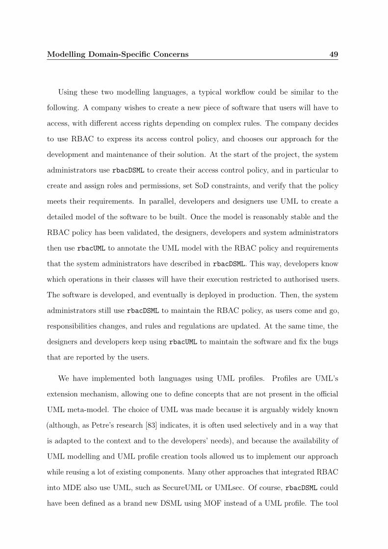
Modelling Domain-Specific Concerns 49
Using these two modelling languages, a typical workflow could be similar to the
following. A company wishes to create a new piece of software that users will have to
access, with different access rights depending on complex rules. The company decides
to use RBAC to express its access control policy, and chooses our approach for the
development and maintenance of their solution. At the start of the project, the system
administrators use rbacDSML to create their access control policy, and in particular to
create and assign roles and permissions, set SoD constraints, and verify that the policy
meets their requirements. In parallel, developers and designers use UML to create a
detailed model of the software to be built. Once the model is reasonably stable and the
RBAC policy has been validated, the designers, developers and system administrators
then use rbacUML to annotate the UML model with the RBAC policy and requirements
that the system administrators have described in rbacDSML. This way, developers know
which operations in their classes will have their execution restricted to authorised users.
The software is developed, and eventually is deployed in production. Then, the system
administrators still use rbacDSML to maintain the RBAC policy, as users come and go,
responsibilities changes, and rules and regulations are updated. At the same time, the
designers and developers keep using rbacUML to maintain the software and fix the bugs
that are reported by the users.
We have implemented both languages using UML profiles. Profiles are UML’s
extension mechanism, allowing one to define concepts that are not present in the official
UML meta-model. The choice of UML was made because it is arguably widely known
(although, as Petre’s research [83] indicates, it is often used selectively and in a way that
is adapted to the context and to the developers’ needs), and because the availability of
UML modelling and UML profile creation tools allowed us to implement our approach
while reusing a lot of existing components. Many other approaches that integrated RBAC
into MDE also use UML, such as SecureUML or UMLsec. Of course, rbacDSML could
have been defined as a brand new DSML using MOF instead of a UML profile. The tool
50 Modelling Domain-Specific Concerns
availability and the ability to reuse existing code ultimately drove our decision to develop
a profile for rbacDSML. Since rbacUML is a DSMAL, i.e. consists of annotations made to
an existing model, a UML profile was the only suitable solution.
DSML vs. DSMAL Selic makes a distinction between profiles where “it is possible
to arbitrarily combine stereotyped elements with non-stereotyped elements in the same
model” [95, p.4], and profiles where “modelers may need to limit their models to only
those UML concepts allowed by a profile” [95, p.4]. He calls the latter a strict application
of a profile. His distinction is at the profile application level, i.e. any profile can be strictly
applied or not, depending on the modeller’s decision. The distinction between strictly
applied profiles and not strictly applied profiles will remind the reader of the distinction
between rbacDSML and rbacUML. Indeed, the rbacDSML profile is applied strictly, i.e. only
rbacDSML constructs are allowed on rbacDSML models, while rbacUML isn’t, i.e. other
UML constructs are allowed on rbacUML models. However, rbacDSML and rbacUML are
different languages. This is where we differ slightly from Selic’s approach. The reason
is that, in rbacDSML, we do not want the same concept (e.g. a user) to be represented
more than once, whilst in rbacUML, we want the same concept to appear wherever it can
be useful to the stakeholders using the model. Hence, the profiles have to differ, and the
differences between rbacDSML and rbacUML are more than a decision to strictly apply a
profile or not.
OCL constraints It this chapter, we use OCL to provide analysis capabilities. We
also propose a classification of OCL constraints, define a partial order between those
categories, and use it to improve the OCL evaluation speed and the feedback given to
the users.

Modelling Domain-Specific Concerns 51
Why RBAC We have decided to limit our approach to RBAC models. RBAC is a
well-known access control model that has been extensively studied, and has even been
standardised. It is therefore very well understood and very well defined. Furthermore,
RBAC is the basis on which other access control models expand, such as OrBAC or
GEO-RBAC, or even ABAC, as we have discussed in the previous chapter. These models
generally add new capabilities to RBAC models. Therefore, an approach that works
for RBAC is already a step in the right direction and could potentially be extended to
support these RBAC extensions. Furthermore, it is always possible to edit the rbacDSML
and rbacUML profiles in order to add the missing constructs and constraints for each
access control model. Future work will be focused on ABAC modelling, and will build
upon the approach presented here for RBAC.
Organisation of this Chapter In the remainder of this chapter, we introduce our
approach for modelling RBAC concepts using OMG standards, namely UML, UML
profiles, and OCL constraints. We do so by using a sample application for a students
marking system, and a workflow that could realistically be applied in a real-life setting: on
an existing application, one wants to implement access control to restrict access to some
functionalities. We first present our application without any access control considerations,
in Section 3.1. Then, we follow Selic’s methodology for DSML development using UML
profiles [95], in Section 3.2. Since both profiles come from the same meta-model, we first
present the meta-model, as well as its associated OCL constraints. We introduce our
categorisation of OCL constraints and present the two categories (out of six) that fit
into Selic’s methodology. We then proceed to describe how we derived the rbacDSML
profile from the domain meta-model, and show how one can apply rbacDSML to create an
RBAC policy for our sample application, in Section 3.3. After that, Section 3.4 describes
how we derived the rbacUML profile from the same domain meta-model, and shows how
we can combine the sample application and the rbacDSML model into an rbacUML model.

52 Modelling Domain-Specific Concerns
After that, we describe the other four categories of OCL constraints, and discuss how one
can use the categorisation of OCL constraints to speed up the evaluation of rbacDSML
and rbacUML models, and how it affects the feedback given to users, in Section 3.5. We
conclude this chapter with a discussion of the contributions, in Section 3.6.
3.1. A Sample UML Model
To illustrate our approach, a small UML model is developed for a system that could be
used in a university. It is first introduced without any consideration for access control, as
per the workflow described below.
The model allows students’ marks to be recorded and accessed. Figure 3.1 shows
a class diagram and a simple sequence diagram, using Rational Software Architect’s
notation. There are small differences between that notation and the standard UML
notation used by the OMG, such as the use of icons to represent the operations and
attributes’ visibility.
The Mark class is where the students’ marks are recorded. The class StudentInfo
represents students, and each student can have any number of marks. A mark, however,
is always assigned to exactly one student. A mark also relates to exactly one module,
represented by the class Module, but a module can of course have any number of marks.
A module is taught by exactly one professor, represented by the class ProfessorInfo.
The professor can have any number of teaching assistants to help them, represented
by the class TAInfo. Of course, a professor can teach several modules, and so can a
TA. Both ProfessorInfo and TAInfo are subclasses of StaffInfo, which represents
members of staff.
All attributes and methods are hidden to save space and improve readability, except
for the Mark class since it will be used to introduce access control.
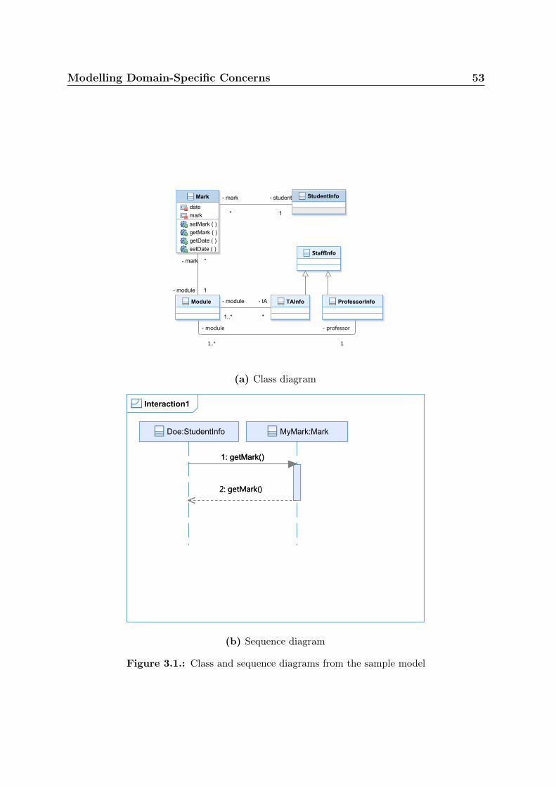
Modelling Domain-Specific Concerns 53
(a) Class diagram
(b) Sequence diagram
Figure 3.1.: Class and sequence diagrams from the sample model
54 Modelling Domain-Specific Concerns
The workflow we will use to illustrate our approach is the following. We start with
the above model, that does not contain any access control information. We will then use
rbacDSML to create a separate model of the access control concepts to be integrated in
the software. Then, we will use rbacUML to merge the rbacDSML model and the UML
model. In the end, both the rbacDSML and the rbacUML models will represent the exact
same access control concepts, and the rbacUML model will be identical to the original
UML model, but with access control information added. We believe that this workflow,
which includes the refinement of the rbacDSML model into and rbacUML model, is quite
realistic. It is, after all, related to MDA’s distinction between PIM and PSM.
3.2. A Methodology for DSML Development Using
UML Profiles
Selic’s methodology for the development of UML Profiles into DSMLs [95] is made of
two parts: first, the construction of the meta-model, carried out in this section; and then,
the mapping of the domain meta-model to the actual profile.
3.2.1. The Meta-Model
Fig. 3.2 represents the proposed domain meta-model, using MOF. It includes Selic’s key
elements: the fundamental language constructs, and the set of valid relationships. All
the standard RBAC concepts are included, as well as scenarios, which are tests that are
meant to ensure that the model meets the stakeholders’ requirements, and resources,
to which access is restricted by the use of permissions. Scenarios involve one user, and
any number of roles (those, of course, need to have been assigned to the user through
user-role associations), in order to access any number of resources, using the permissions

Modelling Domain-Specific Concerns 55
Figure 3.2.: The proposed RBAC domain meta-model (using MOF)
given to the user through the roles associated to the scenario. Together, the users,
roles, permissions and the associations between them represent the configuration. The
resources, together with their permission assignments, form the policy. The scenarios
are composed of the scenario elements together with their associations to users, roles
and resources. It is the navigability that determines access to resources. For example, a
user has access to a resource if there is a navigation path from the user to each of the
permissions associated to the resource, through roles and role hierarchies. The activation
of roles within a session is done through the scenarios, and in particular the associations
between scenarios and roles, named activates. A scenario is therefore a snapshot of
a particular moment during a session, where a subset of the user’s assigned roles are
activated.
The concrete syntax of the languages will be derived from UML through the profiles.
The semantics of users, roles, permissions, their associations and the constraints and
hierarchies are exactly those of the RBAC standard [91]. A user can have any number of
roles; a role can have any number of parents, and can participate in any number of SSoD

56 Modelling Domain-Specific Concerns
and DSoD rules. It can also be assigned any number of permissions. Resources can be
accessed if and only if the user trying to access them has activated a set of roles that
gives them all the permissions required to access said resources. Two types of scenarios
are defined: in the Granted scenario, the user’s activated roles must cover the required
permissions to access all the resources associated to the scenario; in the Forbidden
scenario, the user, having activated the scenario’s roles, must not have all the required
permissions: at least one resource is inaccessible because of a missing permission. The
Forbidden scenarios are called anti-scenarios.
3.2.2. OCL Constraints
To specify how the language concepts can be combined, Selic’s approach requires a set of
constraints that complement the meta-model. He strongly suggests to have them written
in OCL, since it was designed to be used with MOF [95]. In this dissertation, we use
OCL 2.3, which introduced the transitive closure operator, closure().
There are five constraints that specify how the language concepts may be combined.
We discuss them all in this section.
Activated Roles and Assigned Roles
In RBAC, users are only allowed to activate roles that have been assigned to them. In
other words, the set of active roles for a user at any point in time must be a subset of
the set of assigned roles for that user. With our approach, active roles are represented as
part of scenarios. Therefore, the OCL constraint to enforce the role activation property
is the following:

Modelling Domain-Specific Concerns 57
Listing 3.1: Only assigned roles can be activated
c on s t r a i n t Scenar io inv :
s e l f . user . r o l e−>c l o s u r e ( parent )
−>union ( s e l f . use r . r o l e )
−>i n c l ud e sA l l ( s e l f . r o l e )
SSoD
If two roles participate in a static separation of duty rule, then no user can be assigned
both roles. This can be translated in OCL as the following:
Listing 3.2: SSoD constraint
c on s t r a i n t User inv :
s e l f . r o l e−>c l o s u r e ( parent )
−>union ( s e l f . r o l e )
−>e x i s t s ( ro l e1 , r o l e 2 | r o l e 1 . sSoD = ro l e 2 ) = f a l s e
DSoD
If two roles participate in a dynamic separation of duty rule, then no user can activate
both roles at the same time. This can be translated in OCL as the following:
Listing 3.3: DSoD constraint
c on s t r a i n t Scenar io inv :
s e l f . r o l e−>e x i s t s ( ro l e1 , r o l e 2 | r o l e 1 . dSoD = ro l e 2 ) = f a l s e
Granted Scenarios
We have discussed earlier the Granted scenario requirements: the permissions required
to access all the scenario’s resources must be provided by the active roles. This can be
translated into the following OCL constraint:

58 Modelling Domain-Specific Concerns
Listing 3.4: Granted constraint
c on s t r a i n t Granted inv :
s e l f . r o l e
−>c l o s u r e ( parent ) . permis s ion
−>union ( s e l f . r o l e . permis s ion )
−>i n c l ud e sA l l ( s e l f . r e s ou r c e . permis s ion )
Forbidden Scenarios
The Forbidden scenarios are the negation of the Granted scenarios: at least one of the
required permissions must be missing. This leads to the following OCL constraint:
Listing 3.5: Forbidden constraint
c on s t r a i n t Forbidden inv :
s e l f . r o l e
−>c l o s u r e ( parent ) . permis s ion
−>union ( s e l f . r o l e . permis s ion )
−>i n c l ud e sA l l ( s e l f . r e s ou r c e . permis s ion ) = f a l s e
3.3. The rbacDSML Profile
3.3.1. UML Profiles Notation
UML profiles, as we have discussed before, are created by extending the UML meta-model
with stereotypes. Stereotypes can have attributes, as well as associations. Stereotypes can
be applied, or attached, to existing UML elements. UML profiles are defined using MOF.
However, it is not necessary to represent the entire UML meta-model in MOF, together
with the constructs introduced by the profile. It is sufficient to only represent those UML
meta-model elements that are being extended, and all the others are assumed to be left
untouched. For example, Figure 3.3 is the meta-model of the rbacDSML profile, discussed
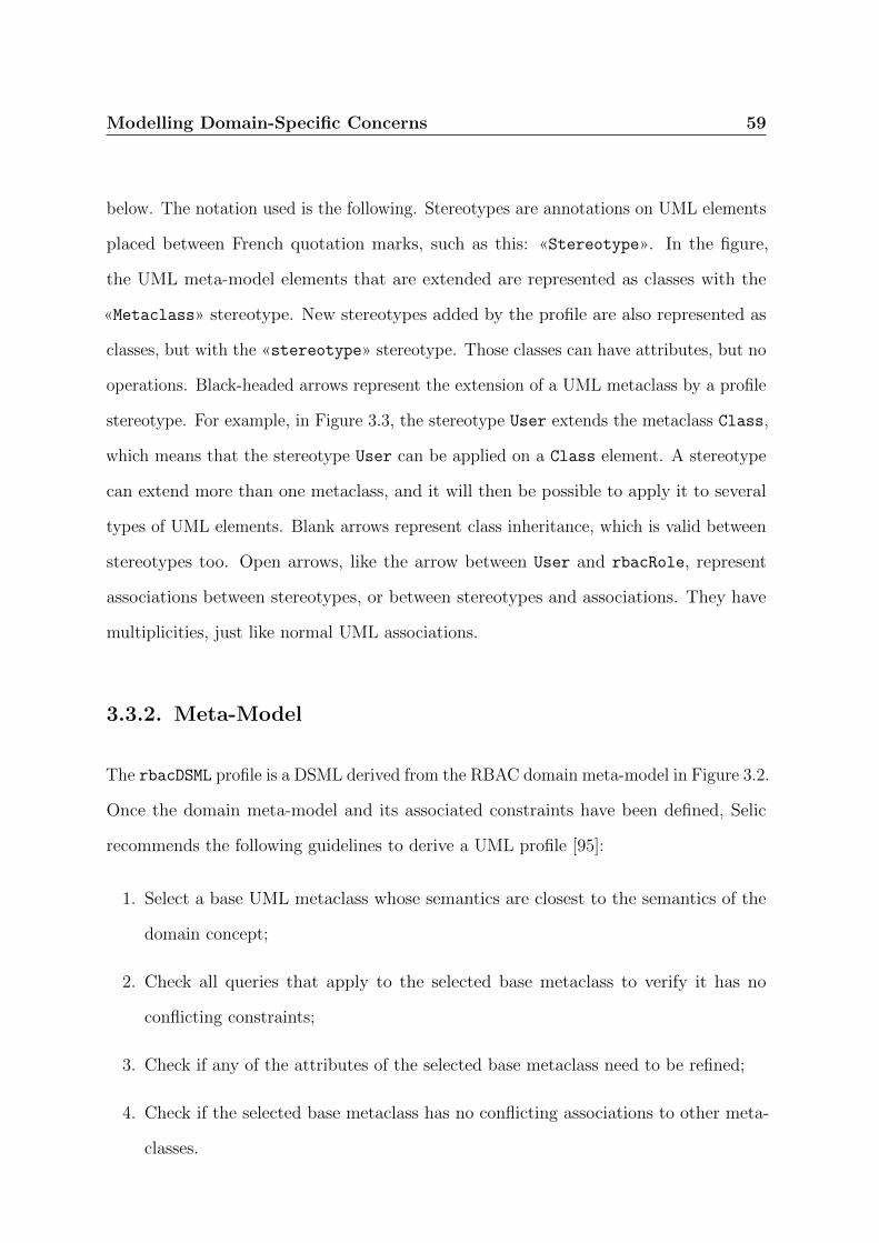
Modelling Domain-Specific Concerns 59
below. The notation used is the following. Stereotypes are annotations on UML elements
placed between French quotation marks, such as this: «Stereotype». In the figure,
the UML meta-model elements that are extended are represented as classes with the
«Metaclass» stereotype. New stereotypes added by the profile are also represented as
classes, but with the «stereotype» stereotype. Those classes can have attributes, but no
operations. Black-headed arrows represent the extension of a UML metaclass by a profile
stereotype. For example, in Figure 3.3, the stereotype User extends the metaclass Class,
which means that the stereotype User can be applied on a Class element. A stereotype
can extend more than one metaclass, and it will then be possible to apply it to several
types of UML elements. Blank arrows represent class inheritance, which is valid between
stereotypes too. Open arrows, like the arrow between User and rbacRole, represent
associations between stereotypes, or between stereotypes and associations. They have
multiplicities, just like normal UML associations.
3.3.2. Meta-Model
The rbacDSML profile is a DSML derived from the RBAC domain meta-model in Figure 3.2.
Once the domain meta-model and its associated constraints have been defined, Selic
recommends the following guidelines to derive a UML profile [95]:
1. Select a base UML metaclass whose semantics are closest to the semantics of the
domain concept;
2. Check all queries that apply to the selected base metaclass to verify it has no
conflicting constraints;
3. Check if any of the attributes of the selected base metaclass need to be refined;
4. Check if the selected base metaclass has no conflicting associations to other meta-
classes.

60 Modelling Domain-Specific Concerns
Table 3.1.: Correspondence between the meta-model and rbacDSML constructs
Meta-model Concept UML Metaclass Stereotype
User Class User
Role Class rbacRole
Permission Class Permission
Resource Class Resource
Scenario Class Scenario
Granted Class Granted
Forbidden Class Forbidden
U-R assignment Association none
SSoD Association SSoD
DSoD Association DSoD
parent Class generalisation none
R-P assignment Association none
guards Association none
accesses Association none
involves Association none
activates Association none
These guidelines, however, only make sense for what we call in this dissertation a
DSMAL, i.e. if one wants to annotate a UML model with domain-specific concepts. In
the case of rbacDSML, we want instead to create a domain-specific language for the sole
purpose of modelling RBAC concerns. Therefore, the choice of base UML metaclasses
is not determined by its proximity to the semantics of the domain concept, but instead
are based on purely syntactical considerations. For rbacDSML, we use UML classes to
represent our meta-model elements, and associations between those classes to represent
the assignments. Table 3.1 shows, for each element and for each assignment in the
meta-model, the chosen metaclass and stereotype in rbacDSML. Several assignments do
not have a stereotype. This is fine because, since rbacDSML is meant for RBAC concepts
only, there are no ambiguities for these associations, even without stereotypes - their
meaning will be determined by the elements they are attached to. For example, U-R
assignment is represented by any association between a user and a role, and guards is
represented by any association between a resource and a permission.
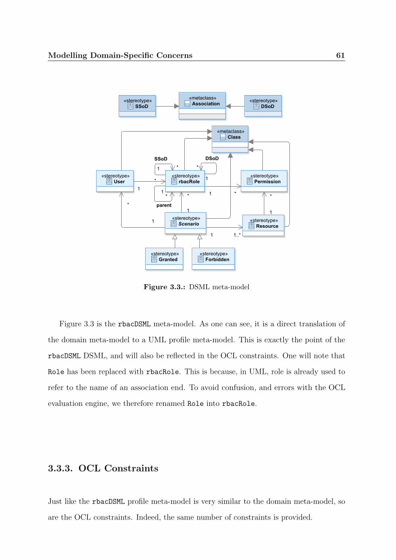
Modelling Domain-Specific Concerns 61
Figure 3.3.: DSML meta-model
Figure 3.3 is the rbacDSML meta-model. As one can see, it is a direct translation of
the domain meta-model to a UML profile meta-model. This is exactly the point of the
rbacDSML DSML, and will also be reflected in the OCL constraints. One will note that
Role has been replaced with rbacRole. This is because, in UML, role is already used to
refer to the name of an association end. To avoid confusion, and errors with the OCL
evaluation engine, we therefore renamed Role into rbacRole.
3.3.3. OCL Constraints
Just like the rbacDSML profile meta-model is very similar to the domain meta-model, so
are the OCL constraints. Indeed, the same number of constraints is provided.

62 Modelling Domain-Specific Concerns
Roles Activation The first constraint makes sure that roles activated by a scenario,
whether a «Granted» or a «Forbidden» one, have been assigned to the user associated
to said scenario.
Listing 3.6: rbacDSML roles activation constraint
c on s t r a i n t rbacDSML : : Scenar io inv :
s e l f . user . rbacRole−>c l o s u r e ( parent )
−>union ( s e l f . use r . rbacRole )
−>i n c l ud e sA l l ( s e l f . rbacRole )
Static Separation of Duty The second constraint deals with the static separation
of duty, and makes sure that no user is assigned two roles that participate in a SSoD
relationship.
Listing 3.7: rbacDSML SSoD constraint
c on s t r a i n t rbacDSML : : User inv :
s e l f . rbacRole−>c l o s u r e ( parent )
−>union ( s e l f . rbacRole )
−>e x i s t s ( ro l e1 , r o l e 2 | r o l e 1 . ssod = ro l e 2 ) = f a l s e
Dynamic Separation of Duty The third constraint deals with the dynamic separation
of duty, and makes sure that no user activates two roles that participate in a DSoD
relationship for the same scenario.
Listing 3.8: rbacDSML DSoD constraint
c on s t r a i n t rbacDSML : : Scenar io inv :
s e l f . rbacRole−>e x i s t s ( ro l e1 , r o l e 2 | r o l e 1 . dsod = ro l e 2 ) = f a l s e

Modelling Domain-Specific Concerns 63
Granted The first verification constraint makes sure that the «Granted» scenarios are
satisfied by the rest of the model - i.e. that the user who performs the scenario is indeed
able to access all the required resources.
Listing 3.9: rbacDSML Granted constraint
c on s t r a i n t rbacDSML : : Granted inv :
s e l f . rbacRole
−>c l o s u r e ( parent ) . permis s ion
−>union ( s e l f . rbacRole . permis s ion )
−>i n c l ud e sA l l ( s e l f . r e s ou r c e . permis s ion )
Forbidden The second verification constraint makes sure that the «Forbidden» sce-
narios are satisfied by the rest of the model - i.e. that the user who performs the scenario
is indeed unable to access at least one of the required resources.
Listing 3.10: rbacDSML Forbidden constraint
c on s t r a i n t rbacDSML : : Forbidden inv :
s e l f . rbacRole
−>c l o s u r e ( parent ) . permis s ion
−>union ( s e l f . rbacRole . permis s ion )
−>i n c l ud e sA l l ( s e l f . r e s ou r c e . permis s ion ) = f a l s e
3.3.4. RBAC Modelling with rbacDSML for the Sample
Application
We can now use the rbacDSML DSML to define the RBAC policy for the sample application
we use to illustrate this chapter. Figure 3.4 shows a possible RBAC policy for the
application, with two Granted scenarios, three users, three roles, two permissions, two
resources, and one SSoD constraint. On the top left are the users, roles and permissions,
and their assignments. On the top right are the two resources that are protected,
Mark_getMark and Mark_setMark. At the bottom are two «Granted» scenarios. The

64 Modelling Domain-Specific Concerns
Figure 3.4.: Sample model with rbacDSML
first one requires that user Smith, with the Professor role activated, must be able to
access the Mark_setMark resource. The second one requires that user Doe, with the
Student role activated, must be able to access the Mark_getMark resource.
3.4. The rbacUML Profile
The other profile that we derive from the domain meta-model is rbacUML. As opposed
to rbacDSML, rbacUML is what we call a DSMAL, i.e. a language used to annotate a
general-purpose model, which is a UML model in this case. Selic’s approach applies
better for rbacUML than it did for rbacDSML, since in this case, it actually makes sense to
select syntactically close UML elements to match the domain-specific elements. Because
the same domain-specific element can sometimes be useful on several types of diagrams,
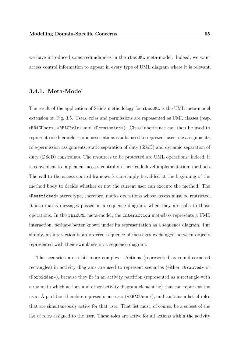
Modelling Domain-Specific Concerns 65
we have introduced some redundancies in the rbacUML meta-model. Indeed, we want
access control information to appear in every type of UML diagram where it is relevant.
3.4.1. Meta-Model
The result of the application of Selic’s methodology for rbacUML is the UML meta-model
extension on Fig. 3.5. Users, roles and permissions are represented as UML classes (resp.
«RBACUser», «RBACRole» and «Permission»). Class inheritance can then be used to
represent role hierarchies, and associations can be used to represent user-role assignments,
role-permission assignments, static separation of duty (SSoD) and dynamic separation of
duty (DSoD) constraints. The resources to be protected are UML operations: indeed, it
is convenient to implement access control on their code-level implementation, methods.
The call to the access control framework can simply be added at the beginning of the
method body to decide whether or not the current user can execute the method. The
«Restricted» stereotype, therefore, marks operations whose access must be restricted.
It also marks messages passed in a sequence diagram, when they are calls to those
operations. In the rbacUML meta-model, the Interaction metaclass represents a UML
interaction, perhaps better known under its representation as a sequence diagram. Put
simply, an interaction is an ordered sequence of messages exchanged between objects
represented with their swimlanes on a sequence diagram.
The scenarios are a bit more complex. Actions (represented as round-cornered
rectangles) in activity diagrams are used to represent scenarios (either «Granted» or
«Forbidden»), because they lie in an activity partition (represented as a rectangle with
a name, in which actions and other activity diagram element lie) that can represent the
user. A partition therefore represents one user («RBACUser»), and contains a list of roles
that are simultaneously active for that user. That list must, of course, be a subset of the
list of roles assigned to the user. These roles are active for all actions within the activity
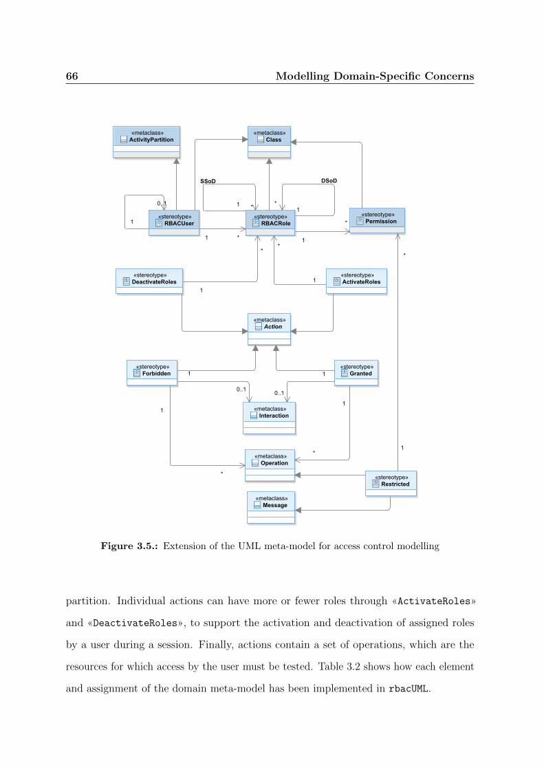
66 Modelling Domain-Specific Concerns
Figure 3.5.: Extension of the UML meta-model for access control modelling
partition. Individual actions can have more or fewer roles through «ActivateRoles»
and «DeactivateRoles», to support the activation and deactivation of assigned roles
by a user during a session. Finally, actions contain a set of operations, which are the
resources for which access by the user must be tested. Table 3.2 shows how each element
and assignment of the domain meta-model has been implemented in rbacUML.
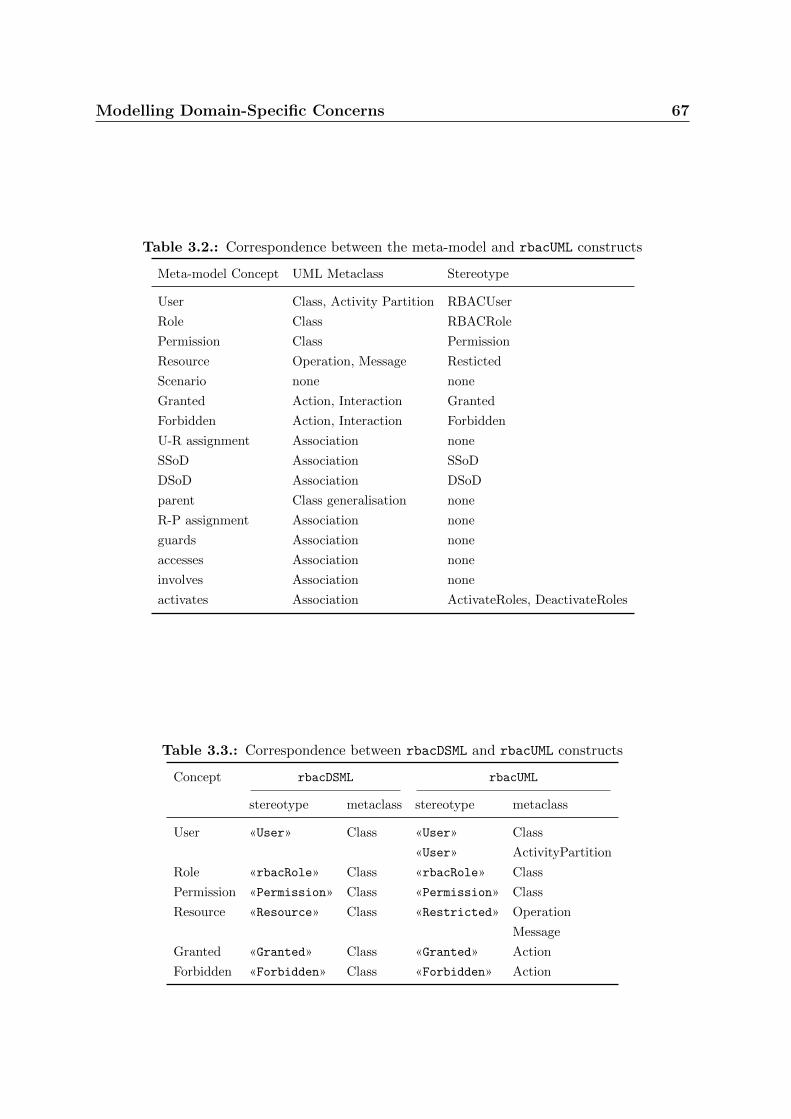
Modelling Domain-Specific Concerns 67
Table 3.2.: Correspondence between the meta-model and rbacUML constructs
Meta-model Concept UML Metaclass Stereotype
User Class, Activity Partition RBACUser
Role Class RBACRole
Permission Class Permission
Resource Operation, Message Resticted
Scenario none none
Granted Action, Interaction Granted
Forbidden Action, Interaction Forbidden
U-R assignment Association none
SSoD Association SSoD
DSoD Association DSoD
parent Class generalisation none
R-P assignment Association none
guards Association none
accesses Association none
involves Association none
activates Association ActivateRoles, DeactivateRoles
Table 3.3.: Correspondence between rbacDSML and rbacUML constructs
Concept rbacDSML rbacUML
stereotype metaclass stereotype metaclass
User «User» Class «User» Class
«User» ActivityPartition
Role «rbacRole» Class «rbacRole» Class
Permission «Permission» Class «Permission» Class
Resource «Resource» Class «Restricted» Operation
Message
Granted «Granted» Class «Granted» Action
Forbidden «Forbidden» Class «Forbidden» Action
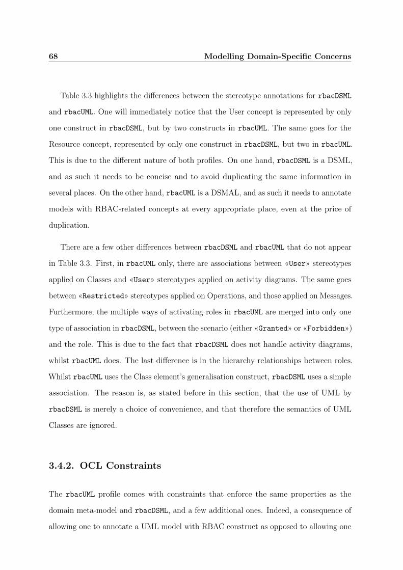
68 Modelling Domain-Specific Concerns
Table 3.3 highlights the differences between the stereotype annotations for rbacDSML
and rbacUML. One will immediately notice that the User concept is represented by only
one construct in rbacDSML, but by two constructs in rbacUML. The same goes for the
Resource concept, represented by only one construct in rbacDSML, but two in rbacUML.
This is due to the different nature of both profiles. On one hand, rbacDSML is a DSML,
and as such it needs to be concise and to avoid duplicating the same information in
several places. On the other hand, rbacUML is a DSMAL, and as such it needs to annotate
models with RBAC-related concepts at every appropriate place, even at the price of
duplication.
There are a few other differences between rbacDSML and rbacUML that do not appear
in Table 3.3. First, in rbacUML only, there are associations between «User» stereotypes
applied on Classes and «User» stereotypes applied on activity diagrams. The same goes
between «Restricted» stereotypes applied on Operations, and those applied on Messages.
Furthermore, the multiple ways of activating roles in rbacUML are merged into only one
type of association in rbacDSML, between the scenario (either «Granted» or «Forbidden»)
and the role. This is due to the fact that rbacDSML does not handle activity diagrams,
whilst rbacUML does. The last difference is in the hierarchy relationships between roles.
Whilst rbacUML uses the Class element’s generalisation construct, rbacDSML uses a simple
association. The reason is, as stated before in this section, that the use of UML by
rbacDSML is merely a choice of convenience, and that therefore the semantics of UML
Classes are ignored.
3.4.2. OCL Constraints
The rbacUML profile comes with constraints that enforce the same properties as the
domain meta-model and rbacDSML, and a few additional ones. Indeed, a consequence of
allowing one to annotate a UML model with RBAC construct as opposed to allowing one

Modelling Domain-Specific Concerns 69
Figure 3.6.: Configuration for the sample model
to only build an RBAC model, is that constraints will be more complex. The duplication
of the elements also requires additional well-formedness constraints: one needs, for
example, to make sure that the name of a user in an activity diagram is identical to its
associated user in the access control diagram. There are 32 well-formedness constraints for
rbacUML, plus the two constraints that verify that the model conforms to the scenarios. In
order to keep this chapter concise, we have included all the constraints in Appendices B.1
and B.2.
3.4.3. Sample application with rbacUML
With rbacUML defined, we can now complete the sample application, by applying the
last step of the proposed workflow: merging the application model with the rbacDSML
model, or, to describe it differently, to extend the rbacDSML model with the application
model. The result is a model made of four types of UML diagrams, with access control
annotations that express exactly the same RBAC concepts as the rbacDSML model.

70 Modelling Domain-Specific Concerns
By annotating the sample model using the rbacUML profile, the configuration (Fig. 3.6)
defines 3 users, 3 roles and 2 permissions, their assignments, the role hierarchies and the
SoD constraints. Professor is a subclass of TA, which means it will inherit all of TA’s
permissions. The SSoD constraint between Professor and Student means no user can
be assigned both roles.
Let us move on to the policy, with the class and sequence diagrams. One will
immediately notice that Figure 3.7a includes a few red classes, which are actually part
of a different diagram discussed earlier: the diagram shown on Figure 3.6. The colour
distinction has been added to the figure to clearly show the limit of the class diagram.
The reason behind this presentation is that there are associations between two different
diagrams. We therefore chose to represent, for each association, the target element on
the other diagram.
The resources to protect are the marks: students should be able to read their marks,
but only professors and TAs should be able to edit them. The class diagram in Fig. 3.7a is
the rbacUML-annotated version of the class diagram in Fig. 3.1a. Two operations have been
annotated with the «Restricted» stereotype: Mark::setMark() and Mark::getMark().
As one can see, the «Restricted» stereotype applied on Mark::setMark() is associ-
ated to the Create Marks permission, which means that the Create Marks permission
will be required for anyone to execute the Mark::setMark() operation. Similarly, the
«Restricted» stereotype applied on the Mark::getMark() operation is associated to
the Access Marks permission. The sequence diagram on Fig. 3.7b is the same as the
diagram of Fig. 3.1b, but the «Restricted» stereotype has been added to the message,
since it is a call to a method whose access is restricted, Mark::getMark().
One still need to define the scenarios to ensure that the model meets the designer’s
requirements. This is done with activity diagrams to make sure that a Professor
can create new marks, and that a Student can read them. In the activity diagram of

Modelling Domain-Specific Concerns 71
Fig. 3.8a, each activity partition stereotyped with «RBACUser» represents a user in the
access control diagram. Here it has two users: Smith, and Doe. Each user is also given
a set of roles that will be active for the whole activity: for Smith, it is Professor, and
for Doe, nothing, to illustrate role activation during a session. This means that Smith
will have the Professor role active for all the actions performed in the activity (unless
specifically deactivated for a particular action), and that Doe will not have any role active.
The activity itself is quite simple, and is made of only two actions. First, Smith performs
Create Marks, and then Doe reads his marks, using Read Mark. One can see that both
actions are stereotyped with «Granted», which means that the users should have the
necessary permissions to perform all the operations associated to those actions. Only
one operation is associated to the Create Marks action: Mark::setMark(), and only
one operation is associated to the Read Mark action: Mark::getMark(). Furthermore,
the Read Mark action is also stereotyped with «ActivateRoles», which means that the
associated roles will be activated for the user on top of those already active. In this case,
Doe gets the Student role, on top of his empty list of active roles.
To further illustrate the capabilities of rbacUML, an activity diagram is created to
define an anti-scenario: actions that a user should not be able to perform. Fig. 3.8b has
only one partition, stereotyped with «RBACUser» to represent a user in the access control
diagram: Doe. He is assigned the Student role for the whole activity, and there is only
one action, Create Mark, stereotyped with «Forbidden», which means that Doe, with
his set of active roles, should not be able to perform all the corresponding operations.
The action is associated to only one operation, Mark::setMark().
One can now verify whether the model enforces the scenarios: in order to be able to
perform the Create Marks action, Smith must be able to perform the Mark::setMark()
operation, which requires the Create Marks permission. Smith has the Professor role
active, which gives him, through its hierarchical relationship with the TA role, the Create
72 Modelling Domain-Specific Concerns
Marks permission. The model thus enforces the first scenario. Similarly, the second
scenario, Read mark, requires Doe to be able to execute the Mark::getMark() operation,
which requires the Access Marks permission: through the Student role he has activated
especially for that action, he gets the Access Marks permission, and the model enforces
the second scenario. The anti-scenario requires that Doe, with the Student role, must not
be able to perform the Create Mark action, which is associated to the Mark::setMark().
As seen before, that operation requires the Create Marks permission, which is not
available through the Student role. Therefore, Doe cannot perform the Create Mark
action, and the anti-scenario is enforced.
3.5. A Taxonomy of OCL Constraints
We have presented earlier several OCL constraints, whose purpose was to complement
the proposed meta-models in order to describe how the languages’ constructs could be
combined. In this section, we propose more types of constraints, as well as a categorisation
of all the constraints in six categories. In this section, we focus on rbacUML, but of course,
the taxonomy presented here also applies to rbacDSML, and the constraints could easily
be translated to rbacDSML as well, since rbacUML is essentially a refinement of rbacDSML.
Selic only mentions one kind of OCL query: well-formedness queries that, together
with the extension of the meta-model, form the DSMAL’s abstract syntax. Here, however,
further support is provided for designers to find out what has not been modelled and
detect redundant elements. Besides the definition of an annotations language with its
syntax and semantics (enforced by well-formedness and verification OCL constraints),
the rbacUML profile provides further modelling support, with OCL constraints to check
the completeness, coverage and redundancy of the configuration and policy, and the
satisfiability of the scenarios. All these queries are implemented as part of the rbacUML

Modelling Domain-Specific Concerns 73
(a) Class diagram
(b) Sequence diagram
Figure 3.7.: Policy for the sample model

74 Modelling Domain-Specific Concerns
(a) Scenario
(b) Anti-scenario
Figure 3.8.: Scenarios for the sample model

Modelling Domain-Specific Concerns 75
Table 3.4.: Summary of severity and type of OCL queries for each category
well-formedness verification satisfiability coverage completeness redundancy
severity error error warning warning warning warning
type constraint constraint query query query query
profile, which means that they are hidden from the designers, who will not have to write
OCL queries themselves for the particular models they work on using the profile. Instead,
they can run the profile queries automatically, and will get feedback if their evaluation
fails.
This section proposes a taxonomy of OCL queries for profiles and describes each
disjoint category. These categories are guidelines to make sure that no queries have been
forgotten, and they complement Selic’s work, since they are not limited to the definition
of a DSMAL. Each category is illustrated by rbacUML, indicating how to systematically
check that no queries have been forgotten. Each category of OCL queries also receives
a severity level, either error or warning. This is because violations of some categories
of queries do not necessarily make a model incorrect. As a general rule, a query should
always be broken down into smaller queries if possible, making it easier to diagnose what
the problem is when a query is violated. Table 3.4 summarises the categories of OCL
queries, their severity level and their type, which can be either a constraint returning a
boolean or a query returning model elements.
3.5.1. Well-formedness
Well-formedness is the first category of OCL queries. It is similar to Egyed’s UML
consistency [28] as discussed in Chapter 2. We focus only on the well-formedness of
the annotations added by the profile. The goal is to ensure that the profile annotations
that define the access control specification on the model are syntactically correct. These

76 Modelling Domain-Specific Concerns
queries are expressed on the configuration, the policy and the scenarios: they must
consider the entire profile to be effective. The rules include well-formedness (some
well-formedness rules described by Selic [95] correspond to Egyed’s consistency rules [28])
between different stereotypes, elements and/or associations. For example, one may want
to make sure that if a class element is stereotyped with A, then it cannot be stereotyped
with B, and vice-versa. Well-formedness queries are the first ones to be defined during
the profile development process, since all the other categories assume a well-formed model
with regard to the UML profile. Well-formedness queries are always constraints.
To make sure that no constraint has been forgotten, profile developers should pay
particular attention to the following:
1) if two stereotypes, or the same stereotype applied on different UML elements,
represent the same domain concept or requirement, well-formedness constraints are
likely to be necessary to enforce that both the elements on which the stereotypes are
applied share some common characteristics, e.g. having the same name. For example,
Section B.1.27 of the appendix shows a constraint that makes sure that the name of an
activity partition on which the «RBACUser» is applied is the same as the name of the
class on which the «RBACUser» is applied and that is linked to the activity partition
using an association;
2) if a stereotype can be applied to more than one type of UML element, multiplicities
in the meta-model may not be correctly enforced, and should therefore be completed
with well-formedness constraints. For example, Section B.1.26 of the appendix shows a
constraint that makes sure that, if the «RBACUser» stereotype is applied on a class, then
there is no alias association from that stereotype. Another constraint, in Section B.1.25
of the appendix, makes sure that if the same stereotype is applied on an activity partition,
then there is exactly one alias association from that stereotype. This cannot be enforced
using the meta-model alone, and therefore, OCL constraints are required;

Modelling Domain-Specific Concerns 77
3) in the case of indirect associations, one may have to check indirect multiplicities
and enforce them through well-formedness constraints, when the indirect multiplicity
must be more restrictive than what the meta-model allows to model through direct
multiplicities. There is no example of such a constraint in rbacUML, but the following
scenario can be considered to illustrate this point: if the number of permissions that each
user can get is limited to N , then one would have to write an OCL constraint that will,
for each user, build the set of roles assigned to them. Then, for each role assigned to the
user, the constraint would build the set of permissions assigned to the role. Finally, the
constraint would merge all the sets of permissions, eliminate duplicates, and make sure
that the size of the set is not larger than N .
In total, rbacUML has 32 well-formedness constraints, listed in Appendix B.1.
3.5.2. Verification
Verification, according to the Capability Maturity Model (CMMI) [2], is “the process
of evaluating software during or at the end of the development process to determine
whether it satisfies specified requirements”. If the DSMAL meta-model allows to express
scenarios, they must be verifiable.
Having specified well-formedness rules will guide the profile developer to implement the
verification queries, which are typically more complex than well-formedness constraints,
and the failure in the evaluation of an instance of such a query must raise an error that
designers have to resolve. Like with the well-formedness queries, verification queries are
actually constraints: either they succeed and the configuration and the policy satisfy
the access control requirements, or they fail and they don’t satisfy the access control
requirements.
78 Modelling Domain-Specific Concerns
In rbacUML, one has two types of scenarios: a user should, or should not, be able to
perform a series of operations with a set of activated roles. Each scenario is an action,
stereotyped with either «Granted» or «Forbidden», within a specific activity partition
representing a user, and given a set of active roles that are a subset of the roles assigned
to said user. Two verification constraints (Appendix B.2) are derived to check whether
the configuration and policy enforce the scenarios: the first one verifies that «Granted»
actions can be performed by the user with the activated roles, and the second one verifies
that «Forbidden» actions cannot be performed by the user with the activated roles.
The first one constructs two sets of permissions: the set of permissions required by the
operations that are part of the considered action, and the set of permissions that the
user has, through the roles s/he has activated. The former set must be a subset of
the latter. The verification constraint for «Forbidden» actions works in a similar way,
but the former set must not be a subset of the latter, i.e. there must be at least one
permission that is required but that the user does not have.
3.5.3. Satisfiability
Satisfiability queries are related to verification queries. Satisfiability queries help answering
the following question: when a scenario is not enforced by the model, is there a particular
element that will always make the scenario fail? For example, an operation stereotyped
with «Restricted» could require more permissions than any user has, or an action
could require more permissions than the user that runs it could get. The evaluation of
satisfiability queries only makes sense if a verification constraint has failed, and therefore
satisfiability queries should be developed after verification constraints. Satisfiability here
is similar to the concept of satisfiability in logic, where a formula is satisfiable if there is
at least one interpretation that verifies it. In rbacUML, a scenario will be satisfiable if

Modelling Domain-Specific Concerns 79
there is at least one user that can execute it, and an anti-scenario will be satisfiable in
there is at least one user that cannot execute it.
In rbacUML, 3 satisfiability queries are specified (Appendix B.3) to help one identify
where the problem lies in case one of the verification constraints is violated.
3.5.4. Completeness
A completeness query identifies areas where elements or annotations are missing, either
intentionally (modelling everything does not always make sense) or not (it is then useful
to point out where something is missing). A completeness problem does not mean that
the model is not correct, so the severity level is warning. Completeness queries deal
with the configuration and the policy, but not the scenarios, as those are dealt with by
coverage constraints (see below).
To find all the possible completeness queries, the associations in the profile must be
considered. If an association has a multiplicity of 0..x, where x could be any integer
or *, then a completeness query is needed: not having any association there might be
intentional, but it may also be a mistake.
In rbacUML, 5 completeness queries are defined in Section B.4 of the appendix.
3.5.5. Coverage
Coverage queries are a kind of completeness queries, but focused on scenarios. As with
the completeness queries, just because scenarios do not cover the entire model does not
mean that the model is incorrect. Therefore, the appropriate severity level is warning.
In software testing, coverage measures the amount of source code that has been tested.
There are several coverage criteria, like the blocks covered, decisions executed or variables
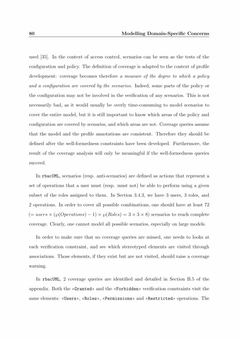
80 Modelling Domain-Specific Concerns
used [35]. In the context of access control, scenarios can be seen as the tests of the
configuration and policy. The definition of coverage is adapted to the context of profile
development: coverage becomes therefore a measure of the degree to which a policy
and a configuration are covered by the scenarios. Indeed, some parts of the policy or
the configuration may not be involved in the verification of any scenarios. This is not
necessarily bad, as it would usually be overly time-consuming to model scenarios to
cover the entire model, but it is still important to know which areas of the policy and
configuration are covered by scenarios, and which areas are not. Coverage queries assume
that the model and the profile annotations are consistent. Therefore they should be
defined after the well-formedness constraints have been developed. Furthermore, the
result of the coverage analysis will only be meaningful if the well-formedness queries
succeed.
In rbacUML, scenarios (resp. anti-scenarios) are defined as actions that represent a
set of operations that a user must (resp. must not) be able to perform using a given
subset of the roles assigned to them. In Section 3.4.3, we have 3 users, 3 roles, and
2 operations. In order to cover all possible combinations, one should have at least 72
(= users × (℘(Operations) − 1) × ℘(Roles) = 3 × 3 × 8) scenarios to reach complete
coverage. Clearly, one cannot model all possible scenarios, especially on large models.
In order to make sure that no coverage queries are missed, one needs to looks at
each verification constraint, and see which stereotyped elements are visited through
associations. Those elements, if they exist but are not visited, should raise a coverage
warning.
In rbacUML, 2 coverage queries are identified and detailed in Section B.5 of the
appendix. Both the «Granted» and the «Forbidden» verification constraints visit the
same elements: «Users», «Roles», «Permissions» and «Restricted» operations. The

Modelling Domain-Specific Concerns 81
coverage queries check which of those model elements are not visited by the verification
constraints.
3.5.6. Redundancy
Redundancy appears when the same concept instance is repeated in the model, i.e.
removing one of them will not affect the evaluation of any of the OCL queries in the
profile. Redundant elements increase the number of elements in the models, which
increases the time necessary to evaluate all the OCL queries and makes the model more
difficult to understand. Redundancies should therefore be eliminated. A redundancy
query is used to find such redundancies, allowing the designer to safely delete one of the
redundant elements, after making sure that the associations pointing to said element are
redirected to the redundant element that will not be deleted, if appropriate. For example,
in rbacUML, if two users, A and B, are found to be redundant, then one of them can be
deleted. If A is to be deleted but an activity partition stereotyped with «User» refers to
A, then this association must be transferred to B and the activity partition’s name must
be changed to B. For the example in Section 3.4.3, if one finds out that two users are
redundant and remove one, the number of necessary scenarios to achieve full coverage is
reduced from 72 to 48.
Redundancy applies to the configuration only. It does not make sense on the policy,
since two operations are never exactly the same, nor does it on the scenarios: if the
same action appears in several places in an activity diagram, or even in several activity
diagrams, this is because of the functional requirements expressed by said diagrams.
Therefore, redundancies should not be removed. The configuration, however, should be
kept as small as possible.

82 Modelling Domain-Specific Concerns
Just as with coverage and completeness queries, redundant elements do not make the
model incorrect, and therefore redundancy queries have a severity level of warning. Yet,
it is recommended to eliminate redundancy as soon as possible.
With rbacUML, 2 redundancy queries are specified in Section B.6 of the appendix.
3.5.7. User-Defined Queries
In addition to the queries provided by rbacUML, users can of course define their own. This
can be useful in several cases. A user could be using a particular authorisation library
that enforces constraints that are not part of the RBAC standard. One such constraint
could be that any role can only have one parent, or that dynamic separation of duty
is not implemented. Designers may also want to provide their own constraints if they
want to perform different types of scenarios in the verification category. For example,
one may want to design a scenario that makes sure that a “default” user does not have
more roles than any other user, or that any user with a specific role also has another one.
Since one uses standard UML technologies, adding a new query or updating an existing
one only requires the designer to edit the relevant OCL queries in the rbacUML profile,
which will be trivial for someone familiar with UML and OCL. If the new query is added
to a particular category, the ordered and selective evaluation strategies will be applied
automatically.
3.5.8. Evaluation of OCL Queries
UML modelling tools typically evaluate all OCL queries on an entire model when the
validation is triggered, which can cause several problems, especially on large models:
• it takes a long time to evaluate all those queries;
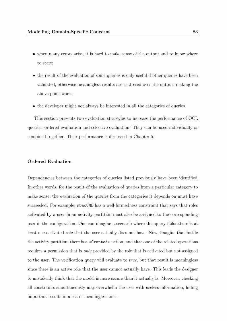
Modelling Domain-Specific Concerns 83
• when many errors arise, it is hard to make sense of the output and to know where
to start;
• the result of the evaluation of some queries is only useful if other queries have been
validated, otherwise meaningless results are scattered over the output, making the
above point worse;
• the developer might not always be interested in all the categories of queries.
This section presents two evaluation strategies to increase the performance of OCL
queries: ordered evaluation and selective evaluation. They can be used individually or
combined together. Their performance is discussed in Chapter 5.
Ordered Evaluation
Dependencies between the categories of queries listed previously have been identified.
In other words, for the result of the evaluation of queries from a particular category to
make sense, the evaluation of the queries from the categories it depends on must have
succeeded. For example, rbacUML has a well-formedness constraint that says that roles
activated by a user in an activity partition must also be assigned to the corresponding
user in the configuration. One can imagine a scenario where this query fails: there is at
least one activated role that the user actually does not have. Now, imagine that inside
the activity partition, there is a «Granted» action, and that one of the related operations
requires a permission that is only provided by the role that is activated but not assigned
to the user. The verification query will evaluate to true, but that result is meaningless
since there is an active role that the user cannot actually have. This leads the designer
to mistakenly think that the model is more secure than it actually is. Moreover, checking
all constraints simultaneously may overwhelm the user with useless information, hiding
important results in a sea of meaningless ones.

84 Modelling Domain-Specific Concerns
Ordering the evaluation of OCL queries brings several benefits:
1. fewer meaningless results;
2. potentially reduced evaluation time, especially when errors are caught early on;
3. possibility of selectively evaluating some categories: for example, one may want to
evaluate verification and completeness queries only, not being interested in coverage
and redundancy queries.
We call this approach ordered OCL query evaluation, as it has similarities with the
ordered evaluation of boolean expressions in some programming languages.
Selective Evaluation
As opposed to ordered evaluation that automatically skips the evaluation of queries
whose result would be meaningless because of the result of other queries further up the
dependency graph, query selection allows the designer to manually select which queries,
or categories of queries, to evaluate at a particular time. For example, a designer might
only be interested in well-formedness queries at some point because he has not given
much thought about the scenarios yet, and therefore it is pointless to run verification
queries. He can then select the well-formedness category only, and only those queries
will be evaluated, no matter what the result of the evaluation is. Similarly, at a later
stage the designer may only be interested in a particular coverage query, that reports
roles that have not been assigned to any user. He can select it and deselect all the other
ones, so no time will be spent on evaluating other coverage queries such as the query
that finds permissions that have not been assigned to any role. This is also a way of
coping with too many errors or warnings resulting from the evaluation of queries that
the designer is not interested in at a particular moment.
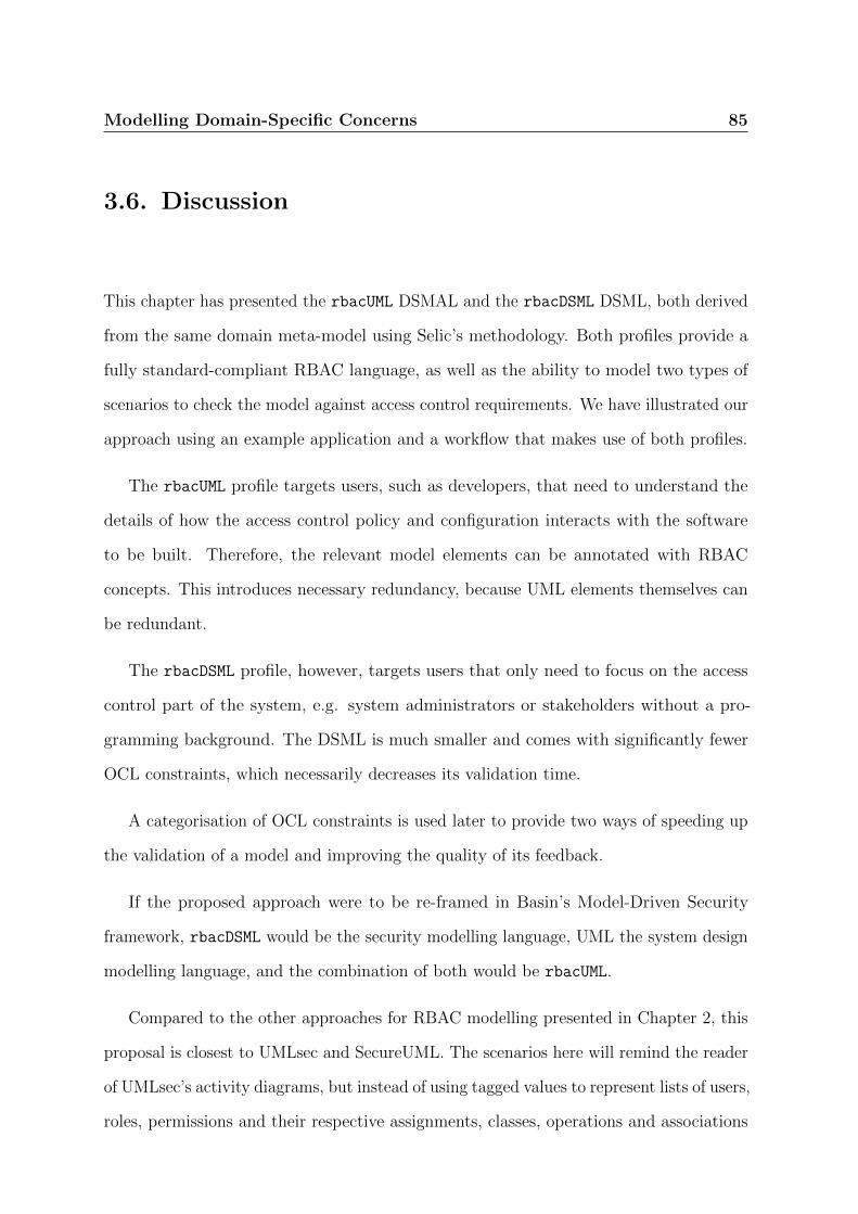
Modelling Domain-Specific Concerns 85
3.6. Discussion
This chapter has presented the rbacUML DSMAL and the rbacDSML DSML, both derived
from the same domain meta-model using Selic’s methodology. Both profiles provide a
fully standard-compliant RBAC language, as well as the ability to model two types of
scenarios to check the model against access control requirements. We have illustrated our
approach using an example application and a workflow that makes use of both profiles.
The rbacUML profile targets users, such as developers, that need to understand the
details of how the access control policy and configuration interacts with the software
to be built. Therefore, the relevant model elements can be annotated with RBAC
concepts. This introduces necessary redundancy, because UML elements themselves can
be redundant.
The rbacDSML profile, however, targets users that only need to focus on the access
control part of the system, e.g. system administrators or stakeholders without a pro-
gramming background. The DSML is much smaller and comes with significantly fewer
OCL constraints, which necessarily decreases its validation time.
A categorisation of OCL constraints is used later to provide two ways of speeding up
the validation of a model and improving the quality of its feedback.
If the proposed approach were to be re-framed in Basin’s Model-Driven Security
framework, rbacDSML would be the security modelling language, UML the system design
modelling language, and the combination of both would be rbacUML.
Compared to the other approaches for RBAC modelling presented in Chapter 2, this
proposal is closest to UMLsec and SecureUML. The scenarios here will remind the reader
of UMLsec’s activity diagrams, but instead of using tagged values to represent lists of users,
roles, permissions and their respective assignments, classes, operations and associations
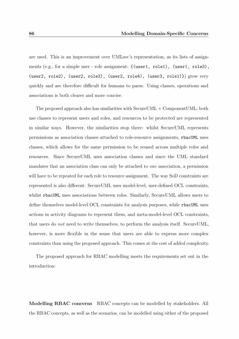
86 Modelling Domain-Specific Concerns
are used. This is an improvement over UMLsec’s representation, as its lists of assign-
ments (e.g., for a simple user - role assignment: {(user1, role1), (user1, role3),
(user2, role2), (user2, role3), (user2, role4), (user3, role1)}) grow very
quickly and are therefore difficult for humans to parse. Using classes, operations and
associations is both clearer and more concise.
The proposed approach also has similarities with SecureUML + ComponentUML: both
use classes to represent users and roles, and resources to be protected are represented
in similar ways. However, the similarities stop there: whilst SecureUML represents
permissions as association classes attached to role-resource assignments, rbacUML uses
classes, which allows for the same permission to be reused across multiple roles and
resources. Since SecureUML uses association classes and since the UML standard
mandates that an association class can only be attached to one association, a permission
will have to be repeated for each role to resource assignment. The way SoD constraints are
represented is also different: SecureUML uses model-level, user-defined OCL constraints,
whilst rbacUML uses associations between roles. Similarly, SecureUML allows users to
define themselves model-level OCL constraints for analysis purposes, while rbacUML uses
actions in activity diagrams to represent them, and meta-model-level OCL constraints,
that users do not need to write themselves, to perform the analysis itself. SecureUML,
however, is more flexible in the sense that users are able to express more complex
constraints than using the proposed approach. This comes at the cost of added complexity.
The proposed approach for RBAC modelling meets the requirements set out in the
introduction:
Modelling RBAC concerns RBAC concepts can be modelled by stakeholders. All
the RBAC concepts, as well as the scenarios, can be modelled using either of the proposed

Modelling Domain-Specific Concerns 87
profiles. There is no requirement for stakeholders to write any code or OCL constraint
themselves. Both profiles also support the entire RBAC standard.
Analysing models Once they have created their RBAC models and requirements,
stakeholders are allowed to analyse said models in one click. The OCL constraints that
implement these analysis features are written at the meta-model level and are part of
the profile.
Classification of OCL constraints and evaluation speed improvements We
provide a classification of OCL constraints in six categories: well-formedness, verification,
satisfiability, completeness, coverage, and redundancy. These categories provide a range of
analysis capabilities. Using this classification, we define a partial order between categories,
allowing us to only evaluate constraints when it makes sense to do so. Therefore, the
number of constraints to evaluate can sometimes be reduced, but is never increased. This
can lead to faster evaluation times. We also provide users with the ability to manually
select which categories of constraints to evaluate, which can also reduce the evaluation
time.
Fewer useless results in the evaluation feedback The partial order between
constraints relies on assumptions made during the constraints creation, e.g. verification
constraints assume that the model is well-formed. The ordered evaluation allows us to
only evaluate constraints if such assumptions are met. Not only does this reduce the
evaluation time, as discussed above, it also removes any feedback on constraints whose
assumptions have not been met, and whose results are therefore meaningless.

88
Chapter 4.
Fixing Models
89

90 Fixing Models
It is not uncommon for the evaluation of rbacDSML or rbacUML models to fail. In fact,
this is true of models in any similar DSML or DSMAL. Especially with large models,
small errors can easily go unnoticed until the evaluation of the OCL constraints points
them out. Furthermore, the very nature of the evaluation engine, where model elements
must satisfy several constraints, makes it rather difficult for designers to manually fix
erroneous models. A change that fixes an error on one instance of an OCL constraint can
result in other instances of the same, or even other, OCL constraints, to raise new errors
that were not there in the first place. These errors will then have to be fixed, potentially
causing more errors elsewhere, until a model that satisfies all instances of all constraints
is produced.
Moreover, by manually fixing their models, designers are likely to overlook or “miss”
possible changes, which would lead them to select a suboptimal or overly complicated
solution to their problem.
Automatically generating a list of valid models that can be derived from an incorrect
one would address these two problems. It would make the designer’s life much easier, as
he would only have to review several correct alternatives, and choose the one that suits
him best. It would also present him with the options he may not have considered had he
tried to manually fix the model.
In this chapter, a graph-based solution for the correction of erroneous models is
presented, discussed and evaluated, under several angles such as completeness, correctness,
and performance. A reference implementation for rbacDSML is also discussed.
4.1. Overview of the Solution
To fix a model is to fix each of the errors raised during its evaluation. However, fixing
an error may introduce another error somewhere else. Furthermore, there usually are

Fixing Models 91
several ways of fixing a particular error, and therefore, several ways of fixing the entire
model. In this chapter, the fixing of individual errors is first considered, regardless of
whether or not a particular fix causes other errors elsewhere on the model.
In rbacDSML, errors can be classified in three categories that will be described in this
chapter, and expressed using graph theory. For each instance of a constraint that needs
to be verified, a graph can be constructed using the elements and associations that are
navigated during the instance’s evaluation. In this graph, nodes are model elements and
edges are associations between elements. The evaluation of the constraint instance is
equivalent to checking a particular property in the graph - such as the presence or the
absence of a cycle. Solutions can then be generated on the graph, by adding or deleting
edges and/or nodes. As there is a one-to-one mapping between the model elements and
the graph nodes, and a one-to-one mapping between the model associations and the graph
edges, it is straightforward to mirror the changes in the graph back to the model. If the
model is a graph, which is the case with UML, then the solutions can be implemented
directly on the model. The fixing of individual errors is described in Section 4.2.
Each error can have several solutions, and in many cases, more than one error will
have to be fixed before the model satisfies all the instances of all the constraints. To fix
the entire model, a tree is created to explore the combined effect of several fixes. The
tree is rooted on the model to be fixed. Each node represents a version of the model,
which can be correct or contain a number of errors. For each model that contains at
least one error, one error is selected and solved. Each generated solution becomes a child
of this node. A solution to fix the entire model is therefore a path from the root to a
leaf that represents a correct model. The solution tree construction and properties are
discussed in Section 4.3.
The number of generated solutions can be a problem, especially on large models
with lots of errors. The more solutions are proposed, the harder it is for designers to

92 Fixing Models
select the best solution. It is therefore crucial to order them in a meaningful way so the
designer will first see the solutions he is most likely to select. The ordering is achieved
by categorising solutions depending on the parts of the model they modify, and on the
number of changes they require. The number of changes in a solution is not the same as
the length of the path between the root and the solution, as fixes for individual errors
can require several changes. This is taken into account when computing the “size” of
each solution, as described in Section 4.4.
The easiest way of constructing the tree is to use a breadth-first or a depth-first
approach. However, this is not the most efficient solution if one wants to get the smallest
solutions as early as possible. In Section 4.5, improvements made to the tree construction
algorithm are discussed, including:
• ordering the fixing of errors depending on the category of the constraints violated,
an approach that is very similar to the ordering of OCL constraints discussed in
Chapter 3;
• allowing users to eliminate some possible solutions that would modify elements or
associations that they are not willing to modify;
• using heuristics to try to find the smallest solutions first.
In Section 4.6, the presentation of the solutions to the designer is examined.
4.2. Generating Fixes for Individual Constraints
4.2.1. Graph Representation of Constraints
DSML models can be seen as graphs whose nodes are elements and edges are associations
between elements. Therefore, the validation of an OCL constraint against a particular
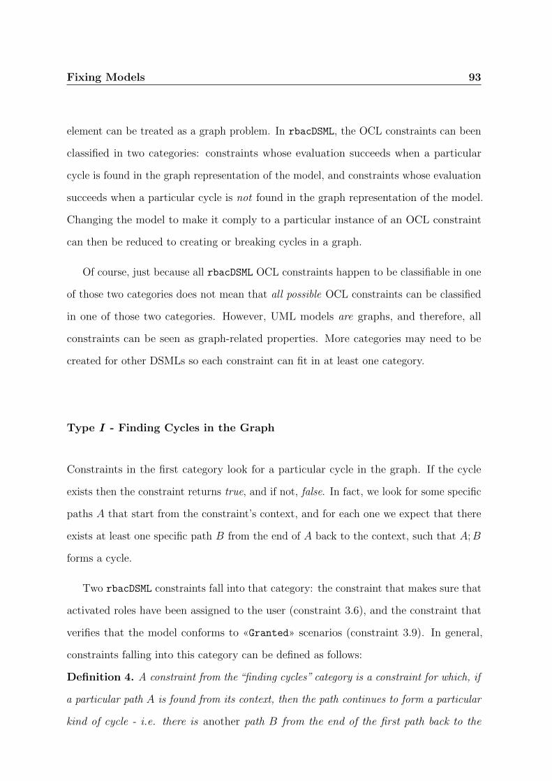
Fixing Models 93
element can be treated as a graph problem. In rbacDSML, the OCL constraints can been
classified in two categories: constraints whose evaluation succeeds when a particular
cycle is found in the graph representation of the model, and constraints whose evaluation
succeeds when a particular cycle is not found in the graph representation of the model.
Changing the model to make it comply to a particular instance of an OCL constraint
can then be reduced to creating or breaking cycles in a graph.
Of course, just because all rbacDSML OCL constraints happen to be classifiable in one
of those two categories does not mean that all possible OCL constraints can be classified
in one of those two categories. However, UML models are graphs, and therefore, all
constraints can be seen as graph-related properties. More categories may need to be
created for other DSMLs so each constraint can fit in at least one category.
Type I - Finding Cycles in the Graph
Constraints in the first category look for a particular cycle in the graph. If the cycle
exists then the constraint returns true, and if not, false. In fact, we look for some specific
paths A that start from the constraint’s context, and for each one we expect that there
exists at least one specific path B from the end of A back to the context, such that A;B
forms a cycle.
Two rbacDSML constraints fall into that category: the constraint that makes sure that
activated roles have been assigned to the user (constraint 3.6), and the constraint that
verifies that the model conforms to «Granted» scenarios (constraint 3.9). In general,
constraints falling into this category can be defined as follows:
Definition 4. A constraint from the “finding cycles” category is a constraint for which, if
a particular path A is found from its context, then the path continues to form a particular
kind of cycle - i.e. there is another path B from the end of the first path back to the

94 Fixing Models
(a) Correct - path A dotted, path B con-tinuous
(b) Incorrect - path A dotted, no path B,no cycle
(c) Correct - three cycles formed by A and B paths
Figure 4.1.: Examples for the Granted OCL constraint
context. In other words, ∀A∃B : A;B : start(A) = end(B), end(A) = start(B), where
start(A) denotes the first node of path A, and end(B) denotes the last node of path B.
The first OCL constraint from rbacDSML to be expressed as a graph is constraint 3.9,
that evaluates the model against «Granted» requirements. For the constraint to be satis-
fied, the set of permissions required by the resources used in the scenario (SPerm required)
must be a subset of the set of permissions activated for the scenario (SPerm activated):
SPerm required ⊆ SPerm activated. Translated to the graph representation, it means that the
path A is a path from the context (i.e. a granted node) to a permission node that passes
through a resource node. The path B completes the cycle by going back to the context
through a role node.

Fixing Models 95
The definition of the constraint can be expressed as the following specialisation of
Definition 4:
Definition 4.1. Given a «Granted» scenario node in the graph representation of the
model, for every path A of length 2 from the scenario to a permission node and through
a resource node, there must be a path B of length 2 from the permission node back to the
scenario, through one role node. Together, these two paths form a cycle.
Figure 4.1 illustrates the constraint for several simple examples. In that figure as
well as in subsequent figures in this dissertation, the following notation applies: nodes
represent UML model elements, except for associations that are represented by edges
between associated nodes. The type of a node is given by the stereotype above its name.
A dotted line represent an association that is part of an A path, while a continuous line
represents an association that is part of a B path. Furthermore, a black border has been
added to those nodes that represent a context element for the OCL constraint considered.
One should also note that the graphs displayed in the figures are subsets of models, where
all elements that are not relevant to the OCL constraint considered have been ignored.
By definition, the context element is also the start of path A and the end of path B.
Figure 4.1a is the smallest correct case: there is one path A between the scenario
and a permission, and there is another path B from the permission back to the scenario,
through a user.
Figure 4.1b is the simplest incorrect case: there is one path A between the context
and the permission, but no path from the permission back to the scenario. Therefore,
the cycle is absent, and the constraint evaluates to false.
Figure 4.1c shows another correct model: there are two paths A1 and A2 between the
scenario and different permissions, and each of these roles is the starting point of a path
B, back to the scenario. There are then two cycles, and the constraint evaluates to true.

96 Fixing Models
The second OCL constraint from rbacDSML in this category is constraint 3.6: to be
satisfied, the set of roles activated by a scenario (either «Granted» or «Forbidden») must
be a subset of the set of roles assigned to the user performing the scenario. Translated to
the graph representation, it means that path A is a path of length 1 from the context (a
scenario) to a role. Path B is a path of length n|n ≥ 2, from the role back to the context
and through a user. The length of the path can be greater than 2 if parent-child edges
have to be followed between roles.
The definition of the constraint can be expressed as the following specialisation of
Definition 4:
Definition 4.2. Given a «Granted» or «Forbidden» scenario as the context in the
graph representation of the model, for every path A of length one from the context to a role
node, there must be a path B of length 2 or more from the role node to the context, through
a user node, and possibly through several roles following parent-child edges. Together,
these two paths form a cycle.
Figure 4.2 illustrates the constraint for several simple examples. The first one
(Figure 4.2a) shows the simplest correct case: the graph contains one path A from a
«Granted» scenario to a role, and one path B from said role back to the scenario through
a user. The constraint’s evaluation returns true.
A counter-example is presented in the second example (Figure 4.2b). There is still
one path A between the scenario and the role, but this time there is no path B from the
role back to the scenario through a user. Therefore, the cycle is broken, and the OCL
constraint’s evaluation returns false.
The third example (Figure 4.2c) shows a more complex correct model. There are
two paths A (dotted) between a «Granted» scenario and two roles. Each path A has a
corresponding path B (plain lines), from the role back to the scenario and through a
user, completing both cycles. The constraint’s evaluation returns true.

Fixing Models 97
(a) Correct - there is a cycle (b) Incorrect - path A dotted, no path B
(c) Correct - paths A dotted, paths B con-tinuous
Figure 4.2.: Graph representation of the rbacDSML constraint ActivateRoles

98 Fixing Models
Absence of Cycles
Constraints in the second category differ from constraints in the first category as they
look for the absence of cycle, instead of their presence. This category can be divided in
two sub-categories. The first one includes the constraints where, for every path A, there
is no path B to complete a cycle. The second one includes the constraints where at least
one path A has no path B to complete its cycle.
Type II - No Cycle at all Constraints in the first sub-category succeed if, for every
path A, there is no corresponding path B to complete the cycle.
Two rbacDSML constraints fall into this sub-category: the SSoD (constraint 3.7) and
DSoD (constraint 3.8) constraints, that ensure that models do not violate separation of
duty constraints. In general, constraints falling into this sub-category can be defined as
follows:
Definition 5. A constraint from the “no cycles” category is a constraint for which, if
a path A is found from its context, then the path does not continue to form a specific
cycle - i.e. there is no path B from the end of the first path back to the context. In other
words, ∀A 6 ∃B : A;B : start(A) = end(B), end(A) = start(B), where start(A) denotes
the first node of path A, and end(B) denotes the last node of path B.
The first OCL constraint from rbacDSML in this sub-category is the SSoD constraint.
Its context is a user. For the constraint to be satisfied, there cannot exist an SSoD
relationship between two roles assigned to the user used as the context. Translated to
the graph representation, it means that the path A is a direct path from the context
to a «rbacRole» node. The path B completes the cycle by going back to the context
through another «rbacRole» node using a SSoD edge, possibly following one or several
child-parent edges before the SSoD edge.

Fixing Models 99
The definition of the constraint can be expressed as a specialisation of Definition 5:
Definition 5.1. Given a user node in the graph representation of the model, for every
path A of length 1 from the user to a role node, there cannot be any path B of length
n|n ≥ 2 from the role node back to the user, through any number of child-parent edges,
and through one SSoD edge. There cannot be a cycle formed by A and B.
Figure 4.3 illustrates the constraint with simple examples. Figure 4.3a is the easiest
correct case: there are two A paths, but no B path.
Figure 4.3b is correct too. There are the same two paths A as in Figure 4.3a. Athough
there is one SSoD edge, it is not part of a B path back to the user.
Figure 4.3c is the simplest incorrect model. The path A, represented by the dotted
line, has a corresponding path B that completes the cycle. Therefore, the constraint
evaluates to false.
Figure 4.3d is another incorrect model. Here, there are not one, but two cycles, each
formed of a path A and a path B.
Figure 4.3e is an incorrect model involving a role hierarchy. Because RO3 is a
descendant of RO1, it inherits its SSoD constraints. There is therefore a path A from the
context to RO3, and a path B from RO3 back to the context, through RO1 and RO2.
The second constraint from rbacDSML in this sub-category is the DSoD constraint.
It is very similar to the SSoD constraint, except that the context is a scenario node
(either «Granted» or «Forbidden»), and role hierarchies are ignored. For a discussion
of separation of duty and role hierarchies, see Section 2.2.4 in the literature review.
The definition of the constraint is therefore very similar to Definiton 5.1, and is also
a specialisation of Definition 5:
Definition 5.2. Given a scenario (either «Granted» or «Forbidden») node in the
graph representation of the model, for every path A of length 1 from the scenario to a

100 Fixing Models
(a) Correct (b) Correct
(c) Incorrect (d) Incorrect - 2 cycles
(e) Incorrect - role hierarchy
Figure 4.3.: SSoD graph examples
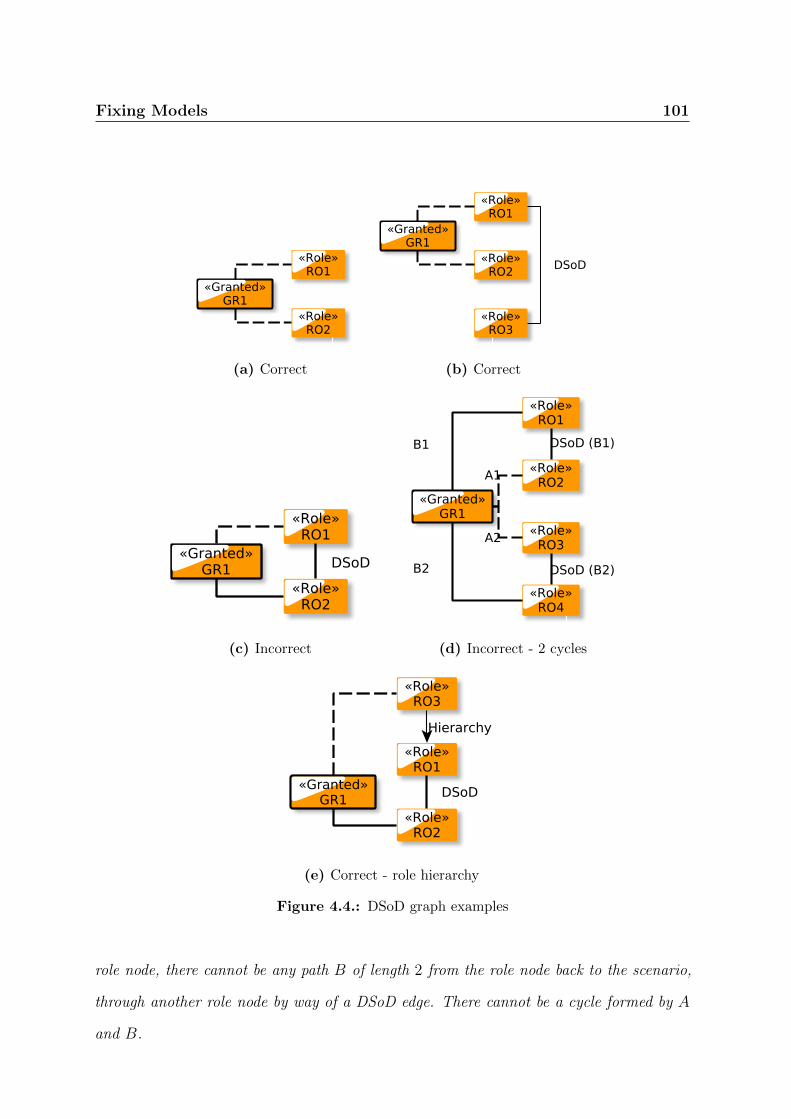
Fixing Models 101
(a) Correct (b) Correct
(c) Incorrect (d) Incorrect - 2 cycles
(e) Correct - role hierarchy
Figure 4.4.: DSoD graph examples
role node, there cannot be any path B of length 2 from the role node back to the scenario,
through another role node by way of a DSoD edge. There cannot be a cycle formed by A
and B.
102 Fixing Models
Figure 4.4 illustrates the constraint with simple cases. They are all very similar to
Figure 4.3 illustrating the SSoD constraint, except that the context is a scenario instead
of a user in Figure 4.3. The first two Figures (4.4a and 4.4b) are correct models, whilst
the last two Figures (4.4c and 4.4d) are incorrect, because they do include cycles. The
last one differs more from the SSoD version. The activation of RO3 does not mean that
its parent RO1 is activated as well, and therefore the DSoD constraint between RO1 and
RO2 is not part of a B path. The constraint thus evaluates to true.
Type III - At Least one Path Without a Cycle Constraints in the second sub-
category succeed if at least one path A has no corresponding path B to complete the
cycle.
Only one rbacDSML constraint falls into this sub-category: the constraint that ensures
that the «Forbidden» scenarios are enforced by the model (constraint 3.10). In general,
constraints falling into this sub-category can be defined as follows:
Definition 6. A constraint from the “at least one path without a cycle” category is a
constraint for which, of all the paths A starting from its context, at least one of them
does not continue to form a specific cycle - i.e. there is at least one path A that does
not have a path B back to the context. In other words, ∃A : 6 ∃B : A;B : start(A) =
end(B), end(A) = start(B), where start(A) denotes the first node of path A, and end(B)
denotes the last node of path B.
The only constraint of this type in rbacDSML is in constraint 3.10, that evaluates the
model against «Forbidden» requirements. The constraint’s satisfaction requirements are
easily derived from the «Granted» constraint (listing 3.9). The set of permissions required
by the resources used in the scenario must not be a subset of the set of permissions
activated for the scenario, i.e. at least one of the required permissions must not be
part of the permissions acquired through the activated roles. Translated to the graph

Fixing Models 103
representation, it means that A is a path from the context (i.e. a «forbidden» node)
to a permission node that passes through a resource node. Path B completes the cycle
(except for at least one path A where there cannot be a path B) by going back to the
context through a role node.
The definition of the constraint can be expressed as the following specialisation of
Definition 6:
Definition 6.1. Given a «Forbidden» scenario node in the graph representation of the
model, there must be at least one path A of length 2 from the scenario to a permission
node and through a resource node, that does not have a corresponding path B of length
n|n > 2, from the permission back through the context, through one role, and possibly
more roles along child-parent edges.
Figure 4.5 illustrates the constraint with a simple example. Figure 4.5a has two
paths A, A1 and A2, but only A1 has a corresponding B path. Therefore, the constraint
evaluates to true.
Figure 4.5b, however, has a B path for each of the A paths, and hence the constraint
evaluates to false.
4.2.2. Generating Possible Fixes
The previous section discussed how to express OCL constraints as graph problems where
specific cycles must be either found or not for the constraint to evaluate to true. Therefore,
a constraint that evaluates to false will either have a cycle where there shouldn’t be
one, or no cycle where there should be one. Fixing a model for it to satisfy a particular
constraint then becomes a matter of either completing or breaking cycles. This section
explores how this can be done, and shows how to generate all the possible fixes for
a particular instance of a constraint only by examining the OCL constraint and the
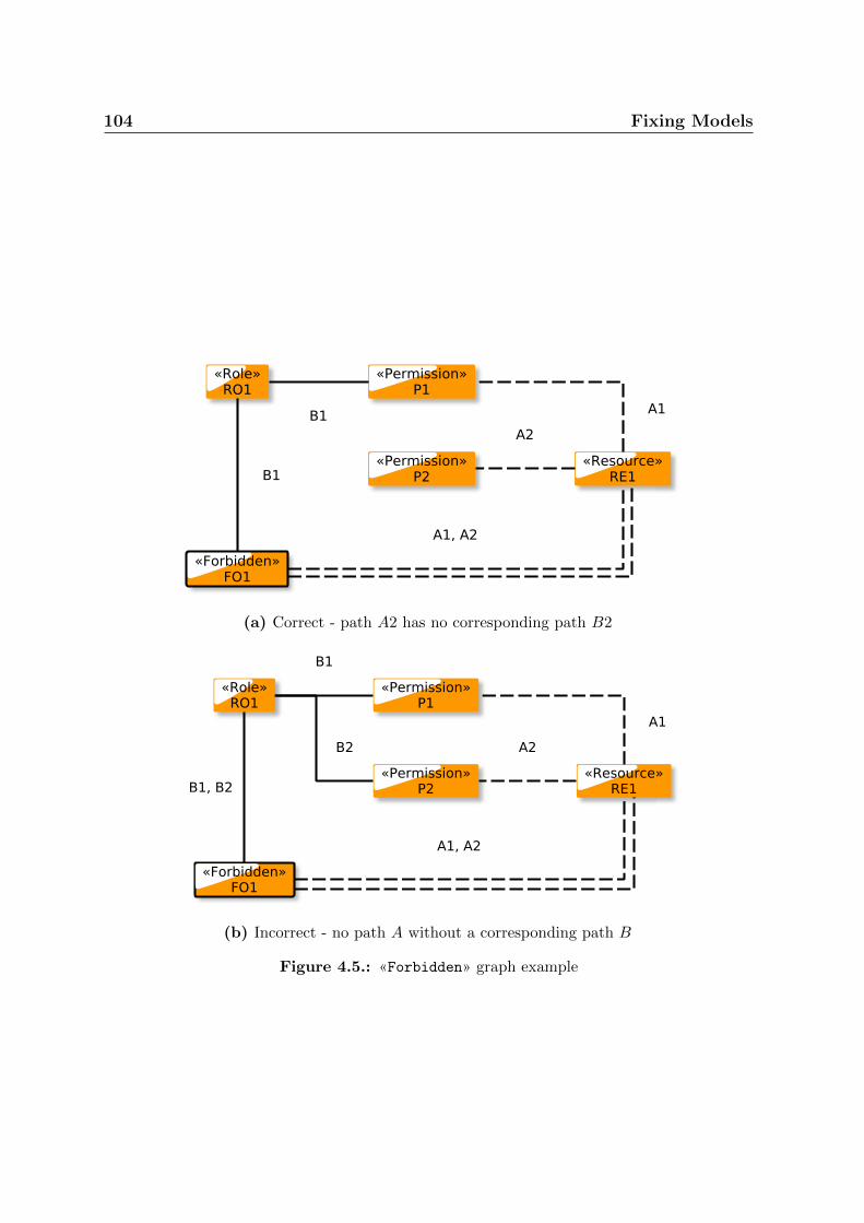
104 Fixing Models
(a) Correct - path A2 has no corresponding path B2
(b) Incorrect - no path A without a corresponding path B
Figure 4.5.: «Forbidden» graph example
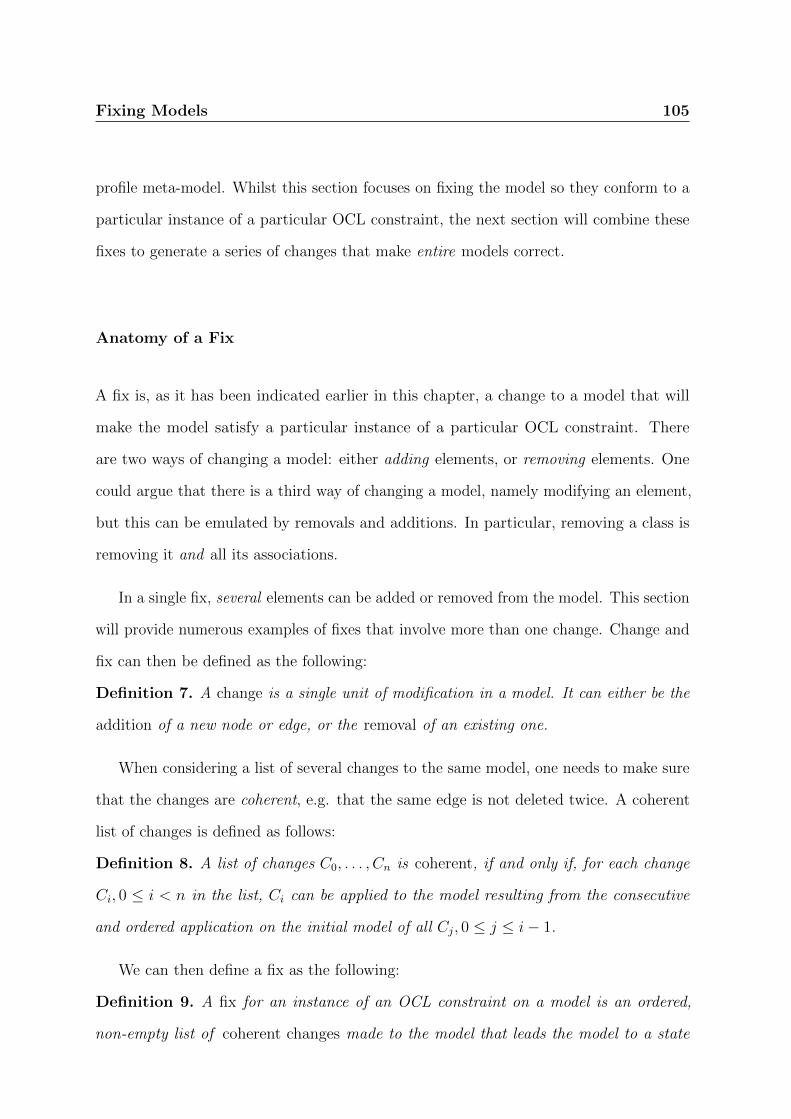
Fixing Models 105
profile meta-model. Whilst this section focuses on fixing the model so they conform to a
particular instance of a particular OCL constraint, the next section will combine these
fixes to generate a series of changes that make entire models correct.
Anatomy of a Fix
A fix is, as it has been indicated earlier in this chapter, a change to a model that will
make the model satisfy a particular instance of a particular OCL constraint. There
are two ways of changing a model: either adding elements, or removing elements. One
could argue that there is a third way of changing a model, namely modifying an element,
but this can be emulated by removals and additions. In particular, removing a class is
removing it and all its associations.
In a single fix, several elements can be added or removed from the model. This section
will provide numerous examples of fixes that involve more than one change. Change and
fix can then be defined as the following:
Definition 7. A change is a single unit of modification in a model. It can either be the
addition of a new node or edge, or the removal of an existing one.
When considering a list of several changes to the same model, one needs to make sure
that the changes are coherent, e.g. that the same edge is not deleted twice. A coherent
list of changes is defined as follows:
Definition 8. A list of changes C0, . . . , Cn is coherent, if and only if, for each change
Ci, 0 ≤ i < n in the list, Ci can be applied to the model resulting from the consecutive
and ordered application on the initial model of all Cj, 0 ≤ j ≤ i− 1.
We can then define a fix as the following:
Definition 9. A fix for an instance of an OCL constraint on a model is an ordered,
non-empty list of coherent changes made to the model that leads the model to a state

106 Fixing Models
(a) Left hand side: an erroneous model,according to an imaginary OCL con-straint
(b) Right hand side: the model, fixed bythe addition of a new node, and thenthe addition of a new edge
Figure 4.6.: A simple example that illustrates why a fix needs to contain an ordered list ofchanges
where the instance of the OCL constraint evaluates to true. A fix only exists for a
particular model if said model, before the fix, causes the instance of the OCL constraint
to evaluate to false.
The above definition specifies that a fix needs to be an ordered list of changes. Consider
the following example, illustrated on Figure 4.6. The model on the left hand side (4.6a)
is the original, and the model on the right hand side (4.6b) is the result of an imaginary
fix for an instance of an imaginary OCL constraint. The fix consists of two changes:
first, adding a new node, and second, adding a new edge between the new and the
existing nodes. It is clear that adding the new node must be done before adding the
edge, otherwise the latter would have a dangling end.
Fixes can be as small as one change, or they can contain a very long list of changes.
Furthermore, depending on the DSML, not all changes are necessarily equal. For example,
in rbacDSML, adding a new role to a model could be treated as a more “expensive”
change than adding a user - role assignment, since presumably, creating a new role in
an organisation is a more serious and less frequent operation than giving someone one
existing role. Therefore, it is interesting to provide a way of computing the weight, or cost,
of a fix. This function is called fcost(F ), for any fix F . The definition of the function
depends on the DSML, and possibly depends on the designer too. A change can have a
cost function too, ccost(C) for any change C, that can be used to compute the cost of
a fix. The simplest cost function would be fcost(F ) = 1, and all fixes, no matter how

Fixing Models 107
Figure 4.7.: There are an infinite number of ways to fix this model
many changes or what kind of changes they contain, would have the same cost. Another
option would be to use the sum of each change in a fix: fcost =∑s
i=1 ccost(Ci), where s
is the number of changes in the fix.
Completeness and Correctness
It is essential for the generation of fixes to satisfy two properties, correctness and
completeness.
Definition 10. Correctness: every fix generated must lead to a model that satisfies
the instance of the OCL constraint considered.
Definition 11. Completeness: the fixes generation algorithm must generate all the
possible changes that would satisfy the correctness criterion.
Verifying correctness is relatively easy: after the model has been changed according
to the proposed fix, the instance of the OCL constraint considered must evaluate to true,
i.e. the model must then satisfy the graph-based definition of the constraint. Verifying
completeness is a bit more challenging. In fact, it is necessary to somewhat restrict the
notion of completeness in order to only generate a finite amount of possible fixes, when
adding elements to the model 1. The problem can be illustrated with an example such
as the example on Figure 4.7. It depicts a rather simple model. The reader will easily
1The deletion of elements from the model (without any addition) is necessarily finite: at most, all theelements will be deleted.
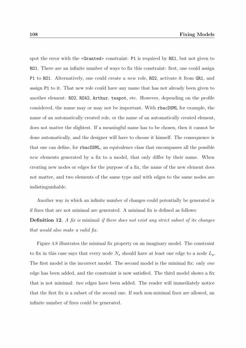
108 Fixing Models
spot the error with the «Granted» constraint: P1 is required by RE1, but not given to
RO1. There are an infinite number of ways to fix this constraint: first, one could assign
P1 to RO1. Alternatively, one could create a new role, RO2, activate it from GR1, and
assign P1 to it. That new role could have any name that has not already been given to
another element: RO2, RO42, Arthur, teapot, etc. However, depending on the profile
considered, the name may or may not be important. With rbacDSML for example, the
name of an automatically created role, or the name of an automatically created element,
does not matter the slightest. If a meaningful name has to be chosen, then it cannot be
done automatically, and the designer will have to choose it himself. The consequence is
that one can define, for rbacDSML, an equivalence class that encompasses all the possible
new elements generated by a fix to a model, that only differ by their name. When
creating new nodes or edges for the purpose of a fix, the name of the new element does
not matter, and two elements of the same type and with edges to the same nodes are
indistinguishable.
Another way in which an infinite number of changes could potentially be generated is
if fixes that are not minimal are generated. A minimal fix is defined as follows:
Definition 12. A fix is minimal if there does not exist any strict subset of its changes
that would also make a valid fix.
Figure 4.8 illustrates the minimal fix property on an imaginary model. The constraint
to fix in this case says that every node Nx should have at least one edge to a node Ly.
The first model is the incorrect model. The second model is the minimal fix: only one
edge has been added, and the constraint is now satisfied. The third model shows a fix
that is not minimal: two edges have been added. The reader will immediately notice
that the first fix is a subset of the second one. If such non-minimal fixes are allowed, an
infinite number of fixes could be generated.

Fixing Models 109
(a) Incorrect model (b) Minimal fix (c) Non-minimal fix
Figure 4.8.: Minimal and non-minimal fixes
These two properties guarantee that the number of possible fixes for any error is a
finite number. We already know that fixes that only differ by the name of the new nodes
will be counted as only one fix, and Definition 12 guarantees that only minimal fixes will
be generated, therefore forbidding the generation of an infinite number of non-minimal
fixes.
Breaking Cycles - Fixing Type II Constraints
Breaking cycles is the easiest type of fix that can be applied. Constraints that fall into
the category where no cycles of a certain type can be found are all expressed as follows:
“If there exists a path A, then there cannot exist another path B that completes a cycle”.
If a cycle is found, there are therefore two solutions: either break A, or break B. These
two solutions can be merged into one: break the cycle formed by A; B.
Of course, breaking a cycle only involves removing a single edge, which represents an
association. Completeness is guaranteed: since there is a finite number of associations in
a model, there is also a finite number of combinations of associations (one for each cycle
to break) to remove.

110 Fixing Models
Since only edges are removed, the order of the changes in a fix do not matter. And
because of the minimal fixes requirement, the number of fixes to generate to break a
cycle is n, a much more manageable number of possibilities. There are n fixes made of
exactly one change, and all other fixes are supersets, and therefore should be discarded.
A generic algorithm that generates minimal fixes for breaking paths2 is Algorithm 1.
Algorithm 1 Generating fixes by breaking a path
function BreakPath(path)fixes← ∅for all edge in path do
fix← new Fix()change← new DeleteChange(edge)Append(fix, change)Append(fixes, fix)
end forreturn fixes
end function
Sometimes, several cycles need to be broken in order to create a fix. Fixes can be
generated for breaking each cycle individually then merged together. A merged fix will
be the concatenation of a fix for each cycle to be broken. Because there can only be
edge removals, there is no need to worry about potential conflicts or order. However,
duplicates are possible, as illustrated in Figure 4.9. In that case, only one of the duplicate
changes is kept in the merged fix. The figure shows the case where both cycles are broken
by deleting the same edge. Figure 4.9a is the incorrect model, which has two cycles.
Figure 4.9b shows a possible fix for the first cycle, whilst Figure 4.9c shows a possible fix
for the second cycle. Instead of merging both fixes into one fix with the same edge to be
deleted twice, there will only be one change in the fix, and the edge will only be deleted
once. The result is shown on Figure 4.9d. Algorithm 2 can be used to merge two fixes.
Algorithm 3 minimises a list of fixes, i.e. removes from the list the fixes that are supersets
of another fix in the list. More fixes can be merged by applying the merging algorithm
2Note that a cycle is a path whose origin and target are the same node.

Fixing Models 111
(a) Incorrect model: two cycles detected (b) Possible fix for the first cycle
(c) Possible fix for the second cycle (d) One fix breaks both cycles
Figure 4.9.: Duplicates when breaking several cycles
several times. Two lists of fixes can be merged with Algorithm 4, while Algorithm 5 will
generate all the fixes for an error, no matter how many cycles there are.

112 Fixing Models
Algorithm 2 Merging two breaking cycle fixes
function Merge(fix a, fix b)fix m← fix afor all change in fix b do
if ¬ Contains(fix a, change) thenAppend(fix m, change)
end ifend forreturn fix m
end function
Algorithm 3 Removing non-minimal fixes from a list
function Minimise(fixes)for all fix a in fixes do
for all fix b in fixes doif Contains(fix a, fix b) then
Remove(fixes, fix a)end if
end forend forreturn fixes
end function
Algorithm 4 Combining the fixes from two lists
function Combine(fixes a, fixes b)fixes← ∅for all fix a in fixes a do
for all fix b in fixes b dofix← Merge(fix a, fix b)if ¬ contains(fixes, fix) then
Append(fixes, fix)end if
end forend forfixes← Minimise(fixes)return fixes
end function
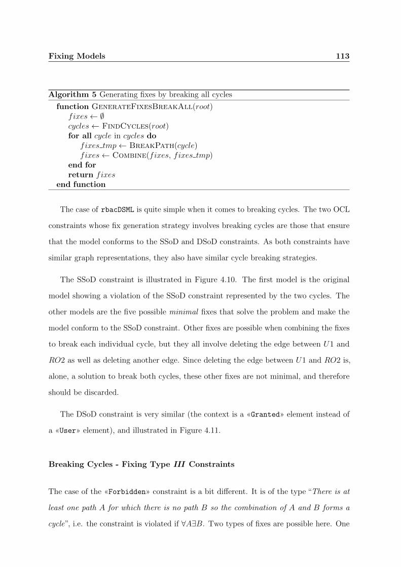
Fixing Models 113
Algorithm 5 Generating fixes by breaking all cycles
function GenerateFixesBreakAll(root)fixes← ∅cycles← FindCycles(root)for all cycle in cycles do
fixes tmp← BreakPath(cycle)fixes← Combine(fixes, fixes tmp)
end forreturn fixes
end function
The case of rbacDSML is quite simple when it comes to breaking cycles. The two OCL
constraints whose fix generation strategy involves breaking cycles are those that ensure
that the model conforms to the SSoD and DSoD constraints. As both constraints have
similar graph representations, they also have similar cycle breaking strategies.
The SSoD constraint is illustrated in Figure 4.10. The first model is the original
model showing a violation of the SSoD constraint represented by the two cycles. The
other models are the five possible minimal fixes that solve the problem and make the
model conform to the SSoD constraint. Other fixes are possible when combining the fixes
to break each individual cycle, but they all involve deleting the edge between U1 and
RO2 as well as deleting another edge. Since deleting the edge between U1 and RO2 is,
alone, a solution to break both cycles, these other fixes are not minimal, and therefore
should be discarded.
The DSoD constraint is very similar (the context is a «Granted» element instead of
a «User» element), and illustrated in Figure 4.11.
Breaking Cycles - Fixing Type III Constraints
The case of the «Forbidden» constraint is a bit different. It is of the type “There is at
least one path A for which there is no path B so the combination of A and B forms a
cycle”, i.e. the constraint is violated if ∀A∃B. Two types of fixes are possible here. One

114 Fixing Models
(a) Incorrect model: two cy-cles detected (b) Solution 1 (c) Solution 2
(d) Solution 3 (e) Solution 4 (f) Solution 5
Figure 4.10.: All the minimal ways of fixing an SSoD error

Fixing Models 115
(a) Incorrect model: two cy-cles detected (b) Solution 1 (c) Solution 2
(d) Solution 3 (e) Solution 4 (f) Solution 5
Figure 4.11.: All the possible ways of fixing a DSoD error

116 Fixing Models
Figure 4.12.: Breaking a path B to fix an error in a «forbidden» constraint. Either of thetwo dotted edges can be removed to break the path
of the paths B could be broken, which would leave an “orphaned” path A. Alternatively,
a new path A could be created so that there is no corresponding path B. It is worth
examining each option separately.
The first option is to break one B path (breaking more than one B path would violate
the minimal fix requirement). This is fairly easy and can be done in a way that is very
similar to Algorithm 5. Note that breaking A would not be an acceptable solution:
that path would simply “disappear” from the constraint evaluation, leaving only cycles.
Algorithm 6 shows how the fixes can be generated. The GetPathB function depends, of
course, on the constraint being considered.
Algorithm 6 Generating fixes; each fix breaks only one cycle
function GenerateFixesBreakOne(context)fixes← ∅cycles← FindCycles(context)for all cycle in cycles do
path← GetPathB(cycle)fix← Break(path)Append(fixes, fix)
end forreturn fixes
end function
Figure 4.12 shows an example of how to fix an error in a «Forbidden» constraint by
breaking one of the paths B.

Fixing Models 117
The second option is to create a new path A that has no path B to complete its cycle.
There are two kinds of fixes to add a path A: the fixes that only create new edges, and
the fixes that also create new nodes.
In the first case, the goal is to create a path A between the context and a target
node that is not already reachable by a path A, while making sure that there is no
path B from that node, by deleting said paths B if necessary. The solution therefore
comes down to adding all the possible combinations of edges that will create such a path.
Each fix should only create one path to avoid violating the minimal changes requirement.
Figure 4.13 is an example of such an operation, on a model that violates a «Forbidden»
constraint. Paths A can be created between the context and one of the following nodes:
P3 or P4. For example, to add a path to P3 (as show in the Figure), the following fixes
are possible:
• add edge between RE1 and P3;
• add edge between RE2 and P3;
• add edge between FO1 and RE3, and add edge between RE3 and P3;
• add edge between FO1 and RE4, and add edge between RE4 and P3.
Of course, on the same example, a path A could be created between the context and
P4, in a similar way. It is not shown on the Figure in order to keep it readable.
Once this is done, there are two possibilities: either there is no path B from P3 back
to the root, and the fix is valid. Or there is a path B, and it should be broken, and the
two fixes should be merged, using the algorithms described in the previous section.
In the second case, the goal is to create a new node, and then to create a path from
the root to it. This works in the same way as the previous case, except that one does not
need to worry about an hypothetical B path: the node is new so there cannot be any.

118 Fixing Models
Figure 4.13.: Fixing error by creating new paths A to P3 (dotted lines are possible additions)
Figure 4.14 is an example of such an operation. Here, permission P5 is added, and all the
possible paths are generated as separate fixes. The following fixes are therefore possible:
• add P5, and add edge between RE1 and P5;
• add P5, and add edge between RE2 and P5;
• add P5, add edge between FO1 and RE3, and add edge between RE3 and P5;
• add P5, add edge between FO1 and RE4, and add edge between RE4 and P5;
• add P5, add RE5, add edge between FO1 and RE5, and add edge between RE5
and P5.
Interestingly, in this sub-category of constraints, there is always only one cycle to break
or one path A to create: any more would violate the minimal changes rule. Therefore, it
is not necessary to merge different fixes.

Fixing Models 119
Figure 4.14.: Fixing error by creating new nodes (dotted lines are possible additions)
Creating Cycles - Fixing Type I Constraints
The last type of fix to be applied is completing cycles. Constraints that fall into the
category where cycles have to be found are all expressed as follows: “If there exists a
path A, then there must exist a path B that completes a cycle”. Therefore, a violation
appears if and only if there is a path A without a path B. This is very similar to the
fixing generation for constraints such as the «Forbidden» verification constraint, except
that the solution is the other way around: either a path A is deleted, or a path B is
created.
Creating a path B can be done using the exact same algorithm as the one used to
create a path A in the previous section. Conversely, deleting a path A can be done using
the exact same algorithm as the one used to delete a path B in the previous section.

120 Fixing Models
Figure 4.15.: Fixing error for «Granted» (possible additions dotted)
In rbacDSML, two constraints can be fixed by creating cycles. The first one is the
«Granted» scenario verification constraint, for which an example is provided in Figure 4.15.
The following operations can be performed to fix the broken cycle problem:
• add edge between P1 and RO2 (shown on figure);
• add edge between RO1 and GR1 (shown on figure);
• add RO3, add edge between P1 and RO3, and add edge between RO3 and GR1;
• delete edge between RE1 and P1;
• delete edge between GR1 and RE1.
The other constraint is the one that makes sure that roles activated by a scenario
have been assigned to the user. This constraint requires a subtle change to the algorithm.
The meta-model extension of UML for rbacDSML defines that there must be exactly
one association from a scenario (either «Forbidden» or «Granted») to a user. This
association could also be represented by an edge on a potential path B. Therefore, the
algorithm that generates path B must be adapted to avoid the creation of a second user,
as it would violate the meta-model. The replacement of a user with another one is made
of two changes: the deletion of the old edge and the addition of the new one. It will be

Fixing Models 121
Figure 4.16.: Creating path B with a meta-model multiplicity constraint (possible additiondotted)
referred to as a replacement for clarity. Figure 4.16 shows a sample model that violates
the constraint. There is a path A from the context to RO1 but not path B from RO1
back to the context. The possible solutions are the following:
• add edge between U2 and RO1 (shown on figure as a dotted line);
• remove edge between GR1 and RO1;
• remove edge between U2 and GR1, and create edge between U1 and GR1.
• create node U3, replace edge between U2 and GR1 with edge between U3 and GR1,
and add edge between U3 and RO1.
The last two possibilities illustrate the change in the algorithm: every addition of an
edge between a user and a scenario must come with the removal of the existing edge
between another user and the scenario, since the scenario can only be associated to one
user.
4.3. Fixing an Entire Model
Fixing an entire model is a complex task: an incorrect model may violate OCL constraints
in many places, and each and every fix to a particular instance of a constraint can in
turn cause other constraint errors that did not exist before. In this section, a general

122 Fixing Models
solution is discussed and analysed. The next section then focuses on how to improve the
algorithm to make it faster.
Any algorithm to generate fixes for an entire model must satisfy several properties,
some of which are similar to the properties that a solution for generating fixes for
individual errors must satisfy:
• Correctness: All the generated fixes must lead to a model that does not violate
any instance of any OCL constraint;
• Completeness: All the possible fixes must be generated, for the designer to be
able to choose the most appropriate one;
• Termination: The generation process must always terminate: it cannot run forever.
4.3.1. Building a Solution Tree
To fix an entire model is to progressively fix individual errors of instances of OCL
constraints, until a model that does not violate any instance of any constraint is produced.
Since there might be several ways to fix each individual error, many different branches
must be explored. In fact, a tree structure is a very way practical to represent the search
for a solution. Figure 4.17 is a very abstract view of the solution. The model to be fixed
is the root of the tree. Each node of the tree is a model, and each edge represents a fix
of a single instance of an OCL constraint. Each node has a state, which is either correct
if the model satisfies all the constraints, in which case that node is a leaf, or incorrect if
there is at least one violation of a constraint. Therefore, each path from the root to a
leaf represents the successive fixes that lead to a correct model.
A naive implementation would therefore use either a depth-first search (DFS) or
a breadth-first search (BFS) approach to progressively construct the tree of possible

Fixing Models 123
Figure 4.17.: Abstract view of the solution tree construction approach
solutions. Algorithm 7 sketches the BFS version of the algorithm. In the algorithm, the
GetModel function creates a model from a node, by successively applying fixes to the
model from the root node down to the node being considered. The GenerateNodes turns
a list of fixes into new nodes that are children of the node passed as the first argument.
The implementation of these two functions depends on the implementation of nodes,
and is not provided here. The GenerateFixes function is not shown in this dissertation
either, as its implementation is trivial but depends on the particular constraints in the
profile, and their categorisation. The function simply detects the constraint that caused
the error, then infers the category it belongs to. It then calls the appropriate function
for the category, e.g. GenerateFixesBreakAll (Algorithm 5).
The DFS version of Algorithm 7 can of course be obtained by replacing the queue
with a stack in the BFS algorithm.
In Algorithm 7, the PickError(Model model) function chooses one of the instances
of OCL constraints that are violated by the model.
The algorithm is simple: starting from the initial model as the root, it progressively
generates all the fixes for a particular instance of an OCL constraint. It stops when all
solutions have been found.
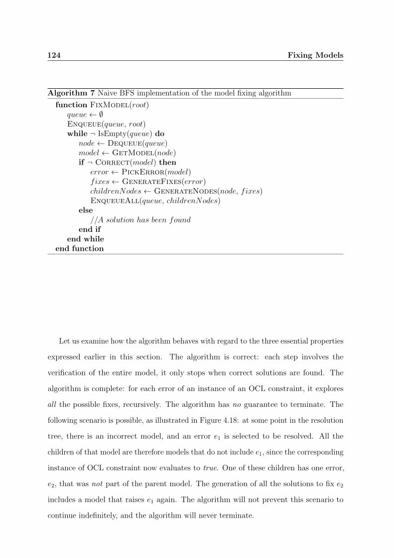
124 Fixing Models
Algorithm 7 Naive BFS implementation of the model fixing algorithm
function FixModel(root)queue← ∅Enqueue(queue, root)while ¬ IsEmpty(queue) do
node← Dequeue(queue)model← GetModel(node)if ¬ Correct(model) then
error ← PickError(model)fixes← GenerateFixes(error)childrenNodes← GenerateNodes(node, fixes)EnqueueAll(queue, childrenNodes)
else//A solution has been found
end ifend while
end function
Let us examine how the algorithm behaves with regard to the three essential properties
expressed earlier in this section. The algorithm is correct: each step involves the
verification of the entire model, it only stops when correct solutions are found. The
algorithm is complete: for each error of an instance of an OCL constraint, it explores
all the possible fixes, recursively. The algorithm has no guarantee to terminate. The
following scenario is possible, as illustrated in Figure 4.18: at some point in the resolution
tree, there is an incorrect model, and an error e1 is selected to be resolved. All the
children of that model are therefore models that do not include e1, since the corresponding
instance of OCL constraint now evaluates to true. One of these children has one error,
e2, that was not part of the parent model. The generation of all the solutions to fix e2
includes a model that raises e1 again. The algorithm will not prevent this scenario to
continue indefinitely, and the algorithm will never terminate.
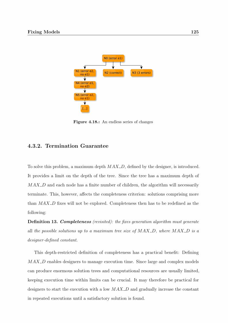
Fixing Models 125
Figure 4.18.: An endless series of changes
4.3.2. Termination Guarantee
To solve this problem, a maximum depth MAX D, defined by the designer, is introduced.
It provides a limit on the depth of the tree. Since the tree has a maximum depth of
MAX D and each node has a finite number of children, the algorithm will necessarily
terminate. This, however, affects the completeness criterion: solutions comprising more
than MAX D fixes will not be explored. Completeness then has to be redefined as the
following:
Definition 13. Completeness (revisited): the fixes generation algorithm must generate
all the possible solutions up to a maximum tree size of MAX D, where MAX D is a
designer-defined constant.
This depth-restricted definition of completeness has a practical benefit: Defining
MAX D enables designers to manage execution time. Since large and complex models
can produce enormous solution trees and computational resources are usually limited,
keeping execution time within limits can be crucial. It may therefore be practical for
designers to start the execution with a low MAX D and gradually increase the constant
in repeated executions until a satisfactory solution is found.
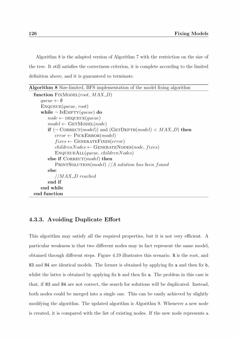
126 Fixing Models
Algorithm 8 is the adapted version of Algorithm 7 with the restriction on the size of
the tree. It still satisfies the correctness criterion, it is complete according to the limited
definition above, and it is guaranteed to terminate.
Algorithm 8 Size-limited, BFS implementation of the model fixing algorithm
function FixModel(root, MAX D)queue← ∅Enqueue(queue, root)while ¬ IsEmpty(queue) do
node← dequeue(queue)model← GetModel(node)if (¬ Correct(model)) and (GetDepth(model) < MAX D) then
error ← PickError(model)fixes← GenerateFixes(error)childrenNodes← GenerateNodes(node, fixes)EnqueueAll(queue, childrenNodes)
else if Correct(model) thenPrintSolution(model) //A solution has been found
else//MAX D reached
end ifend while
end function
4.3.3. Avoiding Duplicate Effort
This algorithm may satisfy all the required properties, but it is not very efficient. A
particular weakness is that two different nodes may in fact represent the same model,
obtained through different steps. Figure 4.19 illustrates this scenario. R is the root, and
N3 and N4 are identical models. The former is obtained by applying fix a and then fix b,
whilst the latter is obtained by applying fix b and then fix a. The problem in this case is
that, if N3 and N4 are not correct, the search for solutions will be duplicated. Instead,
both nodes could be merged into a single one. This can be easily achieved by slightly
modifying the algorithm. The updated algorithm is Algorithm 9. Whenever a new node
is created, it is compared with the list of existing nodes. If the new node represents a
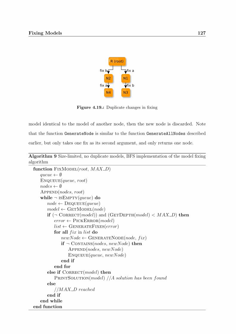
Fixing Models 127
Figure 4.19.: Duplicate changes in fixing
model identical to the model of another node, then the new node is discarded. Note
that the function GenerateNode is similar to the function GenerateAllNodes described
earlier, but only takes one fix as its second argument, and only returns one node.
Algorithm 9 Size-limited, no duplicate models, BFS implementation of the model fixingalgorithm
function FixModel(root, MAX D)queue← ∅Enqueue(queue, root)nodes← ∅Append(nodes, root)while ¬ isEmpty(queue) do
node← Dequeue(queue)model← GetModel(node)if (¬ Correct(model)) and (GetDepth(model) < MAX D) then
error ← PickError(model)list← GenerateFixes(error)for all fix in list do
newNode← GenerateNode(node, fix)if ¬ Contains(nodes, newNode) then
Append(nodes, newNode)Enqueue(queue, newNode)
end ifend for
else if Correct(model) thenPrintSolution(model) //A solution has been found
else//MAX D reached
end ifend while
end function

128 Fixing Models
This solution is still correct, as the update in the algorithm does not affect the
correctness of fixes. It is still complete, since only identical nodes are merged. It still
terminates, as there will be fewer nodes generated.
4.4. Solutions Ordering
The above algorithm will produce the set of all the possible changes made of a designer-
defined maximum number of fixes. That set may be large, especially on large models
with many errors. It is therefore important to order the generated solutions to help
the designer select the most appropriate solution. What the “best” solution is will of
course depend on the DSML being used, and ultimately will come down to the designer’s
specific requirements. However, it is still possible to provide some ordering that will
put the solutions most likely to be selected at the top. Three ordering strategies have
been identified. They can be used independently, or combined together: the cost of fixes,
the type of changes, and the location of changes. In this section, each strategy is first
described and then applied to rbacDSML.
4.4.1. Number of Fixes
The number of fixes is the simplest way of sorting the solutions, and it is independent of
the DSML used. It simply sorts solutions depending on the number of fixes they contain,
i.e. the length of the path between the root and the correct model for each solution in
the solution tree. The solution with the smallest number of fixes will come first, and the
solution with the largest amount of fixes will come last. The idea is that the designer is
likely to select a solution that is not too different from the original model over another
solution that differs more widely from the original model. This is also the order in which,
by definition, the BFS strategy will generate solutions.
Fixing Models 129
However, this strategy is not perfect. It treats all the fixes equally, regardless of
how many changes a fix contains. Therefore, this strategy will not necessarily sort the
solutions from the one that produces a model closest to the original to the one that
produces a model furthest from the original in terms of the number of changes. It does,
however, provide an approximation that might be good enough in some cases.
4.4.2. Cost of Fixes
The cost of fixes is a refinement of the number of fixes approach to sorting the solutions.
Instead of using the number of fixes, it uses the cost of a solution. The cost of a solution
is simply the sum of the costs of each fix: ∀S = {f1, . . . , fn} scost(S) =∑n
i=1 fcost(fi).
Compared to the BFS strategy, this one has the advantage of being more precise: the
cost of each fix will be considered. However, it requires the DSML developer to specify
the fcost() functions.
4.4.3. Type of Changes
The third strategy consists of ordering solutions according to the types of changes that
are part of it. It is different from using the cost strategy with a ccost() function that
returns a different cost for different changes. Instead, it is about classifying solutions in
categories depending on the changes it contains. Changes can be the addition or deletion
of a node, or the addition or deletion of an edge. In some DSMLs such as rbacDSML, this
is an important distinction: adding new roles or permissions may in some cases be out
of the question, but reorganising some assignments may be more acceptable. Ordering
solutions by type of changes allows the designer to focus his attention in priority on the
solutions that include the changes that he finds most acceptable, whilst ignoring those
he does not necessarily approve of.
130 Fixing Models
4.4.4. Location of Changes
The last strategy classifies solutions according to “where” the changes are made. Some
DSMLs such as rbacDSML define models that are made of several “parts” or “locations”.
These can be the type of diagram or elements where the changes are made, or, like in
rbacDSML, a domain-specific distinction such as the difference between the policy, the
configuration and the scenarios. Each solution can be classified in one or several of these
categories, a choice that is made by the developer. It then comes down to the designer
to choose which categories he wants to focus on, and which ones he wants to ignore.
4.4.5. Ordering rbacDSML Models Solutions
rbacDSML is an interesting case study for the ordering of solutions, because it has
three clearly identified, domain-specific “locations”: the policy, the configuration and
the scenarios. These locations can be used to classify the solutions according to their
location.
Within a category, it is possible to sort the solutions according to their cost. In
rbacDSML, the cost of adding a new node is arguably higher than the cost of adding
or deleting an edge (there is no deletion of nodes in rbacDSML, as it would violate the
minimal fix principle). It is then possible to define the cost of a change as follows. If
we consider cn as the addition of a node, and ce the addition or deletion of an edge, we
can define: ∀cn, ccost(cn) = 2, and ∀ce, ccost(ce) = 1. These values can of course be
adapted by the designer if necessary.
In addition to a categorisation by location and the cost-based ordering within cate-
gories, a filter can be defined that shows or hides solutions. The filter comes after the
solutions generation and ordering, and is useful for the designer to only see the solutions
he wants, based on his own criteria, such as whether or not a solution includes the
Fixing Models 131
addition of new nodes. This does make sense in rbacDSML: users, roles, permissions and
resources may very well be a given, and the designer may decide that he does not want to
see solutions that include node additions, or that he does not want to give them priority.
4.5. Improvements
The approach for fixing models described in the previous section may be slow, especially
on large models with lots of errors. It is a great generic solution that applies to any
DSML, but if one is prepared to make use of specific properties of the DSML they are
using, the algorithm can be made much more efficient. In this section, several approaches
are described that aim at reducing the completion time of the algorithm, or at finding
the best solutions faster. The improvements can be used individually or together, and
include the prioritisation of error fixing; the elimination of some specific changes; and
the search for good solutions in priority.
4.5.1. Error Prioritisation
An error arises when an instance of an OCL constraint returns false. It has also been
discussed in Chapter 3 that dependency relationships can be defined between OCL
constraints, and used to more efficiently evaluate a model against a set of constraints.
A similar approach can be taken for the generation of solutions. When selecting which
error to solve, the algorithm could be adapted to take those dependencies into account.
If there is a dependency between constraint A and constraint B such that the result of
the evaluation of B is only meaningful when A evaluates to true, then it should generate
fixes for A first. This will avoid the exploration of some unnecessary branches, by making
sure that only actual errors are fixed.

132 Fixing Models
This approach can be easily implemented by adapting the function that selects the
next error to fix, but it assumes that the dependency graph for the OCL constraints has
been provided by the DSML developer.
4.5.2. Elimination of Undesirable Solutions
Sometimes, while designing his model, the designer knows that there are some changes
he is not willing to perform, either because he does not want to or because he actually
cannot. He may not be willing to add any role in a rbacDSML model. He may not be
willing to change any of the scenarios. He may not want to remove a particular user-role
assignment. Or any other requirement that defines certain solutions as unsatisfactory.
Yet, in ignorance of those requirements, the approach described above will explore those
unsatisfactory solutions anyway. This is a waste of time and computing resources, as the
designer already knows that he will not implement such a solution. Therefore, providing
the designer with a way of describing the changes he does not want to perform, and
adapting the algorithm to take them into account and not waste time exploring those
options, could be a huge time saver.
One way for the designer to express which elements he does not want to see changed
and in what way is through the use of annotations - or, in UML language, through a
profile. This section proposes a set of annotations to attach to elements and associations,
and defines NoChangeUML, a UML profile that implements these annotations. Of course,
the profile can be adapted to other modelling languages than UML, as long as they
provide some sort of annotation mechanism.
The annotations provided by such a language include, but are not necessarily limited
to, the following:
• an association cannot be deleted;
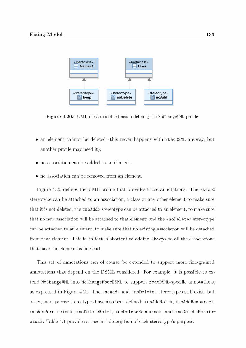
Fixing Models 133
Figure 4.20.: UML meta-model extension defining the NoChangeUML profile
• an element cannot be deleted (this never happens with rbacDSML anyway, but
another profile may need it);
• no association can be added to an element;
• no association can be removed from an element.
Figure 4.20 defines the UML profile that provides those annotations. The «keep»
stereotype can be attached to an association, a class or any other element to make sure
that it is not deleted; the «noAdd» stereotype can be attached to an element, to make sure
that no new association will be attached to that element; and the «noDelete» stereotype
can be attached to an element, to make sure that no existing association will be detached
from that element. This is, in fact, a shortcut to adding «keep» to all the associations
that have the element as one end.
This set of annotations can of course be extended to support more fine-grained
annotations that depend on the DSML considered. For example, it is possible to ex-
tend NoChangeUML into NoChangeRbacDSML to support rbacDSML-specific annotations,
as expressed in Figure 4.21. The «noAdd» and «noDelete» stereotypes still exist, but
other, more precise stereotypes have also been defined: «noAddRole», «noAddResource»,
«noAddPermission», «noDeleteRole», «noDeleteResource», and «noDeletePermis-
sion». Table 4.1 provides a succinct description of each stereotype’s purpose.

134 Fixing Models
Table
4.1
.:Su
mm
aryof
the
stereotyp
esd
efin
edin
NoChangeRbacDSML
stereoty
pe
atta
ched
todescrip
tion
«keep»
Elem
ent
elemen
tor
asso
ciatio
nca
nnot
be
deleted
«noAdd»
Cla
ssn
onew
asso
ciatio
nca
nb
eatta
ched
toth
eelem
ent
«noDelete»
Cla
ssn
oex
isting
asso
ciatio
nca
nb
ed
etach
edfrom
the
elemen
t
«noAddRole»
Cla
ssn
oro
leassig
nm
ent
asso
ciatio
nca
nb
eattach
edto
the
elemen
t
«noAddResource»
Cla
ssn
oreso
urce
assig
nm
ent
asso
ciatio
ncan
be
attached
toth
eelem
ent
«noAddPermission»
Cla
ssn
op
ermissio
nassig
nm
ent
or
requ
iremen
tasso
ciationcan
be
attached
toth
eelem
ent
«noDeleteRole»
Cla
ssn
oro
leassig
nm
ent
asso
ciatio
nca
nb
erem
oved
fromth
eelem
ent
«noDeleteResource»
Cla
ssn
oreso
urce
assig
nm
ent
asso
ciatio
ncan
be
removed
fromth
eelem
ent
«noDeletePermission»
Class
no
perm
ission
assig
nm
ent
or
requ
iremen
tasso
ciationcan
be
removed
fromth
eelem
ent

Fixing Models 135
Figure 4.21.: UML meta-model extension defining the NoChangeRbacDSML profile
4.5.3. Searching for Good Solutions First
The algorithm presented in Section 4.3 has been designed with the assumption that the
algorithm runs to discover all the possible solutions, then returns them, and they are all
displayed to the designer at the same time, after possibly being sorted according to the
sorting strategies described in Section 4.4. The order in which the solutions are explored
therefore does not matter.
One may however improve the designer’s experience by displaying solutions as they
are discovered. The main advantage of this approach is that the designer would see the
first generated solutions much more quickly, and if he finds one that suits him, might
even decide to stop the algorithm before all other solutions have been explored.
However, the order in which solutions are explored becomes important. In other
words, it may make more sense to use a more sophisticated approach than a FIFO queue
or a LIFO stack to select which node to analyse next while constructing the solutions
tree. Several heuristics can be defined to choose which path to explore in priority. These
include the number of errors, the reduction of errors, or the cost of a partial solution.
These can be easily implemented by using Algorithm 9 with a priority queue instead of a
FIFO queue. Each heuristic will then be implemented by a different key computation

136 Fixing Models
Figure 4.22.: Number of errors in intermediate nodes
algorithm for the nodes to insert in the queue. Four heuristics are discussed in this
section. It is also possible to combine several heuristics together.
Heuristic 1: Number of Errors
The first heuristic is fairly simple. Instead of following a BFS or DFS ordering, one could
select, from the set of incorrect model nodes, the one with the smallest number of errors.
The idea behind this heuristic is that models with less errors are likely to be closer to a
correct state, and should therefore be explored in priority. However, this heuristic only
selects a local optimum, which will not necessarily lead to the best solution: a good
solution could involve an increase in the number of errors at some point on its path, and
would then be discarded by the heuristic.
Figure 4.22 shows an example of a fictional model. The number of errors is displayed
next to each incorrect node. We are in the situation where all the nodes have already
been generated, and we need to select one of the leaves to continue fixing errors. Node
N4, which has the smallest number of errors, is the one that will be selected.
This heuristic can be expressed as follows, provided that N represents the set of
incorrect leaf nodes in the tree under construction:
select1(N) = nx|error(nx) = min(error(n0), error(n1), . . . , error(ns)),
where {n0, n1, . . . , ns} = N and x ∈ {0, . . . , s}

Fixing Models 137
Heuristic 2: Reduction of Errors
The second heuristic is similar to the previous one, but instead of looking at the number
of errors in a node, the algorithm looks at the difference between the number of errors in
the parent node and the number of error in the node considered. This way, priority is
given to those nodes that represent models that come closer to a correct state.
The reduction of errors can be expressed as follows, for any n representing an incorrect
leaf node (except the root of the tree): red(n) = errors(parent(n))− errors(n). The
heuristic can then be expressed as:
select2(N) = nx|red(nx) = max(red(n0), red(n1), . . . , red(ns)), where
{n0, n1, . . . , ns} = N and x ∈ {0, . . . , s}
Heuristic 3: Cumulative Cost
The third heuristic considers the cumulative cost of each node. It simply selects the
incorrect leaf node with the lowest fcost(node). This guarantees that the cheapest partial
solution is selected. Assuming that solutions that are closer to the original model are
generally preferable, this is a sound strategy. However, a solution higher up in the tree
will be more likely to be selected: as it has fewer fixes, fcost() is also likely to be lower.
Therefore, in practice, this heuristic will only be a small improvement over the BFS
approach. The heuristic can be expressed as:
select3(N) = nx|fcost(nx) = min(fcost(n0), fcost(n1), . . . , fcost(ns)), where
{n0, n1, . . . , ns} = N and x ∈ {0, . . . , s}

138 Fixing Models
Heuristic 4: Average Cost
In order to address the potential shortcomings of the previous heuristic, one could use
the average cost per node of a path, instead of the cumulative cost. Therefore, short
paths would be less likely to be preferred over longer ones, as long as the latter have an
average cost by node that is smaller than the former’s.
The average costs of errors can be expressed as follows: acost(n) = fcost(n)/length(root, n),
where length(root, n) is the length of the path between the root of the tree and the node
n. The heuristic can then be expressed as:
select4(N) = nx|acost(nx) = min(acost(n0), acost(n1), . . . , acost(ns)), where
{n0, n1, . . . , ns} = N and x ∈ {0, . . . , s}
Combining Heuristics
It is of course possible to combine heuristics into new ones. For example, the number of
errors and the cumulative cost could be used together to decide which node to analyse
next. The score of a node could be computed using a function such as kvv + kfcfc, where
kv and kfc are constant weights, v the number of errors, and fc the cumulative cost. The
node with the lowest score could then be selected.
4.6. How to Present Solutions
Once the solutions have been generated, they need to be returned to the designer in a
meaningful way. The designer must be able to easily identify what each solution consists
of, which problems it solves and which elements have been modified.

Fixing Models 139
In Section 4.4, the order in which the solutions should be presented to the user has
already been discussed. This section, therefore, focuses on how to represent individual
solutions. Designers should be able to visualise each proposed solution individually.
There can be a textual as well as a graphical representation of a solution. They would
include the following information:
• the number and the list of errors in the original model;
• the number of fixes, and the number of changes;
• the list of fixes that lead to the correct model;
• the locations where changes have been made.
With the graphical representation, it is also important to show to the user a diagram
that highlights the differences between the original model and the correct model. Change
description systems, such as UMLChange [50], can be used in this context.
The «addition» stereotype can be attached to the elements or associations that have
been added to the original model, whilst the «remove» stereotype can be attached to
the elements or associations that have been removed from the original model. This is
sufficient to represent all changes, since a change is either an addition or a deletion.
Once the original model has been annotated with UMLChange, its graphical rep-
resentation is a matter of choice to be made by the developer of the tool. One could
simply display the model with the UMLChange stereotypes, or one could also colour the
elements and associations depending on the stereotypes attached (e.g. additions in green
and deletions in red).
Currently, the graphical interface to UMLChange has not been implemented. Only a
textual representation has been implemented. Once the algorithm has stopped, and if
it has found at least one solution, it will present a list of all the possible solutions, in

140 Fixing Models
Figure 4.23.: An incorrect rbacDSML model
the order in which they have been found. Each solution is itself made of a list of fixes,
and each fix is a list of changes. Applying the changes in the order in which they are
displayed on the incorrect model will bring it to a correct state. Below is an example
that describes two possible solutions for the incorrect model shown in Figure 4.23.
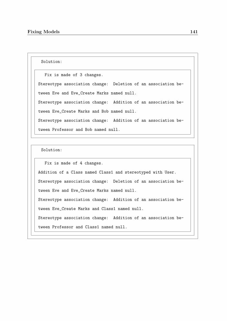
Fixing Models 141
Solution:
Fix is made of 3 changes.
Stereotype association change: Deletion of an association be-
tween Eve and Eve_Create Marks named null.
Stereotype association change: Addition of an association be-
tween Eve_Create Marks and Bob named null.
Stereotype association change: Addition of an association be-
tween Professor and Bob named null.
Solution:
Fix is made of 4 changes.
Addition of a Class named Class1 and stereotyped with User.
Stereotype association change: Deletion of an association be-
tween Eve and Eve_Create Marks named null.
Stereotype association change: Addition of an association be-
tween Eve_Create Marks and Class1 named null.
Stereotype association change: Addition of an association be-
tween Professor and Class1 named null.

142

Chapter 5.
Tool Support
143
144 Tool Support
The features described in Chapters 3 and 4 (except the UMLChange interface that
provides a graphical representation of proposed changes to fix a model), as well as a few
additional ones, are implemented in the tool described in this chapter. The tool is a
suite of plug-ins for the UML modelling IDE, Rational Software Architect (RSA), from
IBM. The source code is released under the Eclipse Public Licence (EPL), and is freely
available online [4]. The implementation for the evaluation and analysis features is a mix
of OCL and Java code.
This chapter is divided into six sections. The first one discusses the choice of developing
a plug-in rather than a standalone tool as well as the choice of the platform. The second
one examines the implementation details. The third section reports on the experience of
working with RSA in particular, and with a modelling platform in general. The following
two sections are dedicated to two studies: the first one compares the various options
for evaluating rbacUML models presented in Chapter 3, and the second one compares
the various options for fixing rbacDSML models presented in Chapter 4. Finally, the last
section presents a real-life case study where we applied rbacUML to ChiselApp, a web
application for hosting and sharing projects with the Fossil distributed version control
system.
5.1. Choosing the Right Platform
In this section, we justify our choice of developing a plug-in for an existing MDE tool,
and our choice of RSA as a modelling tool. We elaborate on the reasons behind those
choices and on the alternatives that we considered. We then elaborate on the architecture
of the selected platform.
Tool Support 145
5.1.1. Plug-In rather than Standalone
At the core of rbacUML, is the desire to integrate rbacUML as much as possible into
designers’ existing activities, processes and tools. Since the DSML and DSMAL parts
of the rbacUML approach are defined as UML profiles, tight integration with existing
UML modelling tools was greatly valued. A plug-in seemed to be the right choice, and it
was confirmed by a few other considerations. Developing a plug-in would allow to use
existing diagramming capabilities, instead of having to implement it ourselves. Since
OCL constraints were a big part of the approach, reusing an existing OCL evaluation
engine was also a great argument in favour of a plug-in over a standalone tool.
5.1.2. Comparing Available Modelling Environments
Once it was clear that a plug-in was going to be developed instead of a dedicated tool, the
platform to build it on had to be chosen. Three platforms were selected for evaluation,
according to the following list of requirements:
• UML modelling capabilities: the tool must support the UML 2.x standard;
• OCL queries evaluation engine: since rbacUML’s analysis capabilities are based on
OCL, an efficient and expressive engine, i.e. a full OCL implementation, is a must;
• Support for custom UML profiles: the rbacUML DSML and the rbacDSML DSMAL
are represented as UML profiles, so the ability to define custom profiles and to use
them within the platform is crucial;
• UML diagrams creation support: models in rbacUML are represented using several
types of diagrams: class diagrams, sequence diagrams and activity diagrams. It is
therefore essential that the platform allows one to easily create at least those three
types of diagrams;
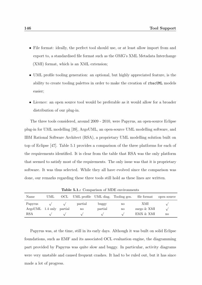
146 Tool Support
• File format: ideally, the perfect tool should use, or at least allow import from and
export to, a standardised file format such as the OMG’s XML Metadata Interchange
(XMI) format, which is an XML extension;
• UML profile tooling generation: an optional, but highly appreciated feature, is the
ability to create tooling palettes in order to make the creation of rbacUML models
easier;
• Licence: an open source tool would be preferable as it would allow for a broader
distribution of our plug-in.
The three tools considered, around 2009 - 2010, were Papyrus, an open-source Eclipse
plug-in for UML modelling [39], ArgoUML, an open-source UML modelling software, and
IBM Rational Software Architect (RSA), a proprietary UML modelling solution built on
top of Eclipse [47]. Table 5.1 provides a comparison of the three platforms for each of
the requirements identified. It is clear from the table that RSA was the only platform
that seemed to satisfy most of the requirements. The only issue was that it is proprietary
software. It was thus selected. While they all have evolved since the comparison was
done, our remarks regarding these three tools still hold as these lines are written.
Table 5.1.: Comparison of MDE environments
Name UML OCL UML profile UML diag. Tooling gen. file format open source
Papyrus√ √
partial buggy no XMI√
ArgoUML 1.4 only partial no partial no zargo & XMI√
RSA√ √ √ √ √
EMX & XMI no
Papyrus was, at the time, still in its early days. Although it was built on solid Eclipse
foundations, such as EMF and its associated OCL evaluation engine, the diagramming
part provided by Papyrus was quite slow and buggy. In particular, activity diagrams
were very unstable and caused frequent crashes. It had to be ruled out, but it has since
made a lot of progress.
Tool Support 147
ArgoUML is the only of the three platforms not to be based on Eclipse. It is a stable
product, but only supports UML 1.4, does not support profiles and has limited OCL
support. It had to be ruled out as well.
RSA was the last platform considered. Like Papyrus, it is built on Eclipse and uses
EMF and the associated OCL evaluation engine. RSA comes as a layer on top of Eclipse,
providing different features, the most notable one being a very mature UML modelling
and diagram editing environment. Furthermore, RSA was the only tool allowing one to
very easily create tooling palettes for our profile. It uses EMX to store models, an XML
format that looks very similar to XMI, and allows for export to and import from XMI.
Whilst it is not an open source project, IBM has an “academic initiative” programme
giving academics free access to its products, including RSA.
The RSA platform is built on top of Eclipse, and makes extensive use of the Eclipse
Model Development Tools (MDT) project. It provides many features, but in this section
the focus is on those directly relevant to our work.
RSA provides a diagram edition layer on top of Eclipse UML, as well as the ability to
define UML profiles and automatically generate code for editors that include said profiles.
RSA’s extensive use of Eclipse MDT technologies makes UML-related projects developed
for RSA relatively easy to port to other Eclipse-based tools that also make use of MDT.

148 Tool Support
5.2. The rbacUML Plug-In
In this section, we describe the implementation of the rbacUML plug-in [64], and discuss
which Eclipse and RSA technologies the plug-in uses.
5.2.1. The Rational Software Architect Modelling Stack
At the bottom of the UML modelling stack is the Eclipse Modeling Framework (EMF),
which uses the Ecore meta-model. On top of EMF is UML2, an EMF implementation
of the UML 2.x standard using UML. In other words, the UML meta-model is defined
using EMF, and Ecore is therefore used as UML’s meta-meta-model.
Eclipse also includes an implementation of an OCL engine, also built on top of EMF,
allowing one to parse OCL constraints and use them to evaluate EMF models. In the
last few years, the Eclipse project underwent an important change in the implementation
of the OCL engine, and two separate implementations co-existed for the duration of
the transition [27]. The mature OCL meta-model provides a parser and an evaluation
engine for both Ecore and UML2 model. It is, however, tightly coupled to Ecore, causing
some performance issues and making it difficult to stick to the OCL 2.2 standard. In
particular, it makes it very difficult to create and evaluate OCL constraints that work on
annotations provided by UML profiles. The new OCL meta-model, called pivot OCL,
addresses the shortcomings of the mature OCL meta-model, and complies to the OCL
2.2 standard.
On top of Eclipse MDT comes RSA, which uses the UML modelling and mature
OCL meta-model features to provide additional features. The most obvious one is a
very efficient UML diagramming capability, allowing one to represent UML2 models as
diagrams (class, sequence, activity, etc.) instead of “simply” the trees provided by the
Eclipse UML2 project. Another feature is the profile tooling generator, that allowed us
Tool Support 149
to easily create UML profiles and automatically generate a RSA plug-in to use the profile
in UML models.
5.2.2. The UML Profiles
Building the UML profiles was the first step in the tool’s implementation. We were able
to make use of RSA’s profile tooling project capabilities, which allowed us to (1) create
the stereotypes, specify the types of elements on which they can be attached, and define
the associations between the stereotypes, graphically; (2) for each stereotype, specify
the appropriate OCL constraints; (3) generate the tooling model and customise it; and
(4) generate the tooling code, producing a usable RSA plug-in with a tooling palette
allowing designers to directly create stereotyped elements.
rbacUML, the DSMAL
The rbacUML DSMAL has been implemented according to its description in Chapter 3,
and contains all the OCL queries in Appendix B. There has been no modification at all.
rbacDSML, the DSML
The rbacDSML DSML, on the other hand, differs slightly from its description in Chapter 3.
The reason for the differences comes down to implementation problems, and limitations
or bugs of the RSA and Eclipse platforms.
Firstly, instead of associations between stereotypes, UML associations have been used.
The reason for this change is that associations between stereotypes are not treated by
RSA as “real” UML model elements, which has a few annoying consequences:

150 Tool Support
• it is not possible to attach stereotypes to associations between stereotypes, making
it impossible to annotate fixed models with UMLChange annotations;
• the navigation of associations between stereotypes is unidirectional. Whilst it is
possible to navigate them in the opposite direction, it is complex
• the visual representation of the associations between stereotypes is separated from
their existence on the model. As a consequence, it is possible to delete an arrow from
a diagram without deleting the corresponding association on the model. Similarly,
it is possible to add an association without the arrow appearing on the relevant
diagrams. This is likely to be a bug in RSA, and does not appear with “real” UML
associations.
For these reasons, the stereotype associations have been replaced by UML associations.
Another issue arose from the role hierarchies. The OCL standard provides a transitive
closure operator, closure(), but only since its version 2.3. RSA having been released
before then, it will flatly refuse to even parse an OCL constraint with the closure operator,
if it is included in a profile. There is at least one partial workaround to overcome this
limitation, but it is not perfect. Fortunately, RSA happily provides the allParents()
operation, which gives the transitive closure of a Class’s superclasses. It has then been
decided to represent role hierarchies in this fashion, exactly like it is done with rbacUML.
Because of these two changes, the OCL constraints for the rbacDSML implementation
slightly differ from their description in Chapter 3. The implemented version of the
constraints can be found in Appendix A.

Tool Support 151
5.2.3. Visualisation of Large Configurations
Any diagrammatic modelling approach suffers from problems with the visualisation of
models with many elements. However, two measures mitigate this problem for rbacUML.
The first one comes from rbacUML’s design, where the RBAC configuration and the
business logic are clearly separated and represented on two different diagrams: the access
control diagram for the configuration, and a standard class diagram for the business
logic, including the annotations that indicate which operations must have their access
restricted to authorised users only.
The second one is a visualisation feature we implemented in the plug-in, namely the
designer has the ability to select from the model a list of users, roles and permissions,
and to transfer them to the access control diagram in one click. Not only will the selected
users, roles and permissions appear on the diagram, but so will all the roles assigned to
the selected users, all the users, permissions, parents and children of the selected roles,
and all the roles assigned to the selected permissions. Through a smaller diagram, it
provides a clear picture of the relationships between the selected elements. Since the
verification is made on the model and not on the diagrams, this has no impact on the
result of the evaluation of OCL queries.
5.2.4. Import from LDIF
Often, an organisation will use the same user directory for several applications. This
saves a lot of time in user administration, and helps prevent a lot of conflicts and update
problems. LDAP and Active Directory are very popular solutions, and both export
in the LDIF format. rbacUML is capable of reading an LDIF file to populate a model
automatically. Users in the file are mapped to users in the model, while groups in the
152 Tool Support
file are mapped to roles in the models. If a group A is a member of a group B, then in
the rbacUML model, A will be a child of B.
It is quite likely that several users in the file will have the same set of groups. They
can be regarded as redundant for modelling purposes, and rbacUML will suggest to merge
them into one single user in the model. Information about all the merged users is
kept on the model in order to allow for the LDIF file to be regenerated from the model
if necessary. Our importer directly translates the content of the LDIF file into XML
Metadata Interchange (XMI), the format used for representing UML models, and is
therefore usable by any UML modelling tool.
5.2.5. Selective Evaluation of OCL Queries
We have implemented the selective OCL query evaluation, giving designers full control
over which OCL queries to evaluate by simply selecting the queries or categories of
queries to evaluate. Designers can also chose if they want to run an ordered evaluation or
not. Since our OCL constraints are defined in a UML profile, it is easy for developers to
edit the profile in order to add, remove or modify OCL constraints. Their classification
in one of the categories that we have defined is done on the basis of the query name:
well-formedness queries start with WF, verification queries with VER, satisfiability queries
with SAT, coverage queries with COV, completeness queries with COMP, and redundancy
detection queries with RED. Therefore, developers can easily place their new or updated
query in the category of their choice by giving them an appropriate name. Queries will
then automatically be picked for evaluation in the correct category. Currently, it is not
possible for developers to create a new category or to change the dependency relationships
between categories, unless of course they are willing to modify the tool’s source code.

Tool Support 153
5.2.6. Model Generator
Another feature of the rbacUML plug-in is the model generator. It has been developed
as part of a performance study of the tool. Its purpose is to generate random rbacUML
models, either correct or incorrect depending on the user’s choice, of a specified size.
We used it to calculate the evaluation time of increasingly large models, as well as to
compare the “full” evaluation of a model with the ordered evaluation.
Unlike the LDIF import filter, the model generator has not been implemented by
directly generating XML documents. Instead, we made use of Eclipse UML’s features,
that allow one to very easily create UML model elements - including stereotypes from an
existing UML profile.
5.2.7. Fixing Incorrect Models
Finally, the last feature of the tool is the fixing of incorrect rbacDSML models. Implemented
in Java but using the rbacDSML OCL constraints to verify the model, the fixing feature
generates solutions to fix incorrect models, as described in Chapter 4. Designers have
the opportunity to choose from a selection of traversal strategies as well as constraint
selection strategies, to set the maximum height of the solutions tree, and to set the
maximum number of solutions to return.
5.3. Working with Rational Software Architect
This section contains a discussion of the advantages and disadvantages of working with
RSA. The positive aspects are presented as well as the negative aspects, in the hope that
it may be useful for developers of DSMLs or DMSALs on top of UML, as well as for
further improvements of the platform.

154 Tool Support
5.3.1. The Good
There were many advantages in using the Eclipse platform in general, and RSA in
particular, to build the rbacUML tool.
The Profile Builder
Using the UML profile builder to create rbacUML proved to be a huge time saver. Indeed,
the ability to define the stereotypes and their associations graphically, but also to use
the built-in editor to define the OCL constraints, all without writing a single line of
non-OCL code, was a much faster way to develop and test our profile than having to
manually write the profile as an XMI document. It also made it very easy to come back
to the profile to fix a bug, add a new feature or test several alternatives for a particular
construct.
The Profile Tooling Generator
The profile tooling generator was probably one of RSA’s features that saved us the most
time. The ability to generate in one click a tooling palette to help designers create
rbacUML models, and generate a RSA-based environment dedicated to rbacUML were
incredibly valuable, as the alternative would have been to write all that code manually.
The generator also allows for many parameters to be configured before the code is
generated, allowing us to tailor the generated tool to our exact needs and requirements.
The OCL Engine
To evaluate OCL constraints, we used Eclipse’s OCL validation engine, a much better
solution than writing our own engine. Eclipse’s OCL engine is very powerful and highly
Tool Support 155
configurable. RSA even provides a button to evaluate all the OCL constraints associated
to a model in a single click, and when we had to dive deeper into the code to write our
own evaluation procedure for selective and ordered evaluations, the OCL engine could be
configured to do what we wanted it to do.
Creating UML Elements
Programmatically creating UML elements, but also navigating elements through associ-
ations, was greatly facilitated by the Eclipse UML component, which does a great job
at hiding the underlying complexity of the model. This provided numerous advantages
compared to directly editing the EMX files (like we did for the LDIF import filter), or
even the EMF or Ecore representations.
The Use of Standard Tools and Formats
The fact that both Eclipse and RSA use (mostly) standard technologies and formats was
very useful to keep the tool generic enough that it could be ported to other platforms. In
fact, the LDIF import filter is even platform-independent: thanks to RSA’s usage of the
standard XMI format, any tool that also uses XMI can read models created from the
filter.
The standard-compliant OCL engine is also worth noting: since it supports the OCL
standard, the OCL constraints we wrote can be copied verbatim to another tool with
a standard compliant OCL evaluation engine. Furthermore, since RSA uses Eclipse’s
engine, rbacUML should be relatively easy to port to other Eclipse-based tools such as
Papyrus.
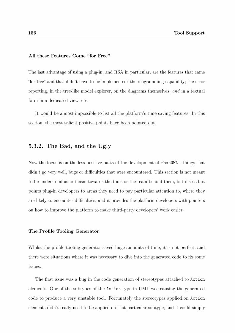
156 Tool Support
All these Features Come “for Free”
The last advantage of using a plug-in, and RSA in particular, are the features that came
“for free” and that didn’t have to be implemented: the diagramming capability; the error
reporting, in the tree-like model explorer, on the diagrams themselves, and in a textual
form in a dedicated view; etc.
It would be almost impossible to list all the platform’s time saving features. In this
section, the most salient positive points have been pointed out.
5.3.2. The Bad, and the Ugly
Now the focus is on the less positive parts of the development of rbacUML - things that
didn’t go very well, bugs or difficulties that were encountered. This section is not meant
to be understood as criticism towards the tools or the team behind them, but instead, it
points plug-in developers to areas they need to pay particular attention to, where they
are likely to encounter difficulties, and it provides the platform developers with pointers
on how to improve the platform to make third-party developers’ work easier.
The Profile Tooling Generator
Whilst the profile tooling generator saved huge amounts of time, it is not perfect, and
there were situations where it was necessary to dive into the generated code to fix some
issues.
The first issue was a bug in the code generation of stereotypes attached to Action
elements. One of the subtypes of the Action type in UML was causing the generated
code to produce a very unstable tool. Fortunately the stereotypes applied on Action
elements didn’t really need to be applied on that particular subtype, and it could simply

Tool Support 157
be removed from the list of elements on which the stereotypes could be applied - and the
tooling code could then be regenerated.
The second issue was not a bug, but had to do with the way the code generator works,
and with the incremental way we developed the UML profile. Usually we were adding
new elements at each iteration, but occasionally we had to delete elements as well, as we
realised that a particular RBAC construct could be better or more succinctly expressed
with another construct. The tooling code generator works in a quite conservative way,
to make sure that user-defined code is not overwritten unless necessary. Therefore,
re-running the generator after it has already run at least once will not result in the
generator wiping out the existing code and replacing it by its own, but instead, it will
only overwrite files that it generates, and leave the others alone. This means that, if an
element is removed, the implementation of the related features will be left in the code
(since they are not generated anymore), and cause compilation problems. It is then the
users’ responsibility to go through all the compilation errors and remove the now useless
classes and references to elements that do not exist anymore. This is a problem we are
trying to solve using bidirectional transformations to synchronise user changes with the
generated models [114].
Bugs
We encountered a few annoying bugs in the platform, that forced us to develop workarounds
and/or dive into the lower layers of the platform. In particular, known bugs in the OCL
evaluation engine made it more difficult to navigate associations between stereotypes.
Furthermore, parts of the evaluation engine couldn’t actually deal with OCL queries that
returned non-boolean values, even though the documentation indicates otherwise. This
prompted us to rewrite these queries so they would return boolean values, or to use a
lower level of abstraction to get around the problem.

158 Tool Support
There were also bugs that made it impossible to navigate stereotype associations in
Java using the UML abstraction level, and we had to use the underlying representation.
The Size of the Platform
The Eclipse platform is huge, and so is the RSA platform. Combined, they form a
gargantuan set of technologies, built to work on top of or in combination with each
other. While this obviously provides immense benefits, it also comes with its faults and
weaknesses. It can be very difficult and intimidating for developers that are new to the
platform to get a working understanding of how all the pieces fit together. RSA includes
some documentation, which frequently refers to the Eclipse documentation, but dead
links are not uncommon. Furthermore, the IBM academic initiative does not include
any support from IBM or Rational, so we were left on our own to figure out how the
platform works and what its limitation are, only with the help of the documentation,
which is often incomplete. We also used the community support, via the IBM forums or
websites such as Stackoverflow [105], but got very few (if any) answers on some of the
most advanced questions. It seems that there is not a massive community of advanced
OCL users, or if it exists, we have yet to find it.
Learning how to use the platform requires a large time investment, especially for
developers that do not have an Eclipse/RSA expert handy. We had to learn about the
Eclipse platform, about plug-in development for Eclipse, about the Eclipse MDT project
and its limitations, and about RSA. We then had to put all that information together
and figure out how these projects relate to each other. It took us months, and we are
still learning every day. We are documenting our experience to make it easier for the
community to develop similar modelling plug-ins for the Eclipse or RSA platforms.
Tool Support 159
Limitations to Dissemination
Our choice of RSA as a platform did most probably limit the potential for dissemination
of rbacUML. Indeed, whilst RSA is available for free to academics, few are willing to
make the effort to deploy it, most notably because of the rather large amount of online
paperwork to fill, the obligations that come together with the IBM academic initiative,
and the lack of support for Mac OS X (although there is now a preview version of RSA
8.5 for Mac OS X). Non-academics were understandably reluctant to invest in costly
RSA licence fees, which made it very difficult to reach out to industry.
In order to mitigate this issue, we tried to avoid using RSA-specific APIs as much as
possible, and instead try to rely on Eclipse MDT alone whenever possible. We have been
much more successful at this with our most recent developments, and one of the added
benefits is that there is less documentation to deal with. While currently RSA is still
required to run our plug-in, we hope that, by further diminishing our reliance on IBM’s
proprietary APIs, and thanks to the progress of open-source tools such as Papyrus, we
will be able to migrate to a fully open source platform in the near future, which will
doubtlessly make it easier for third parties to use, and perhaps contribute to or build
upon our plug-in.
5.3.3. Discussion
This section has focused on the implementation of the rbacUML approach. The choice of
implementing the tool as a plug-in of an existing MDE platform was quite straightforward
as it allowed for a very tight integration of our approach with existing practice. From the
experience reported above, the following suggestions can be derived to help individuals
or organisations willing to take on a similar route.

160 Tool Support
• Plug-Ins are definitely the way to go to achieve excellent integration very quickly.
The amount of time saved by the ability to reuse existing components is perhaps
the best argument in favour of using a plug-in;
• If interoperability is a concern, one should be very careful about the platform’s
support of standards;
• Sufficient time will have to be allocated to acquire in-depth knowledge of the
platform. Even the lower layers may have to be used to get around bugs and
problems;
• If the tool is meant to be used by a large public, the platform must be carefully
chosen to make it as easy as possible to adopt.
Overall, the rbacUML experience has been positive, and further development is under
way to integrate the rbacUML approach even more with designers’ MDE workflow.
5.4. rbacUML Evaluation Performance
In order to assess the scalability of rbacUML, we measured the query evaluation time.
We focused on four variables: the size of the model (the number of elements + the
number of associations), the result of the evaluation (success or failure), the usage of our
ordered evaluation and/or selective evaluation approaches, and the usage of parallelised
evaluation for categories of queries that have the same dependencies.
For the first variable, we wrote a model generator that can generate random and
correct models (i.e. models that pass all well-formedness and verification queries) of a
specified size. The generator is available online with the rbacUML plug-in [4]. It allows
one to create rbacUML models in both the XMI and the EMX formats. The user provides an
XML file that describes the size of the model he wants to generate. Several parameters

Tool Support 161
can be set, such as the number of users, roles, permissions, «Restricted» operations,
«Granted» and «Forbidden» actions, etc. Ranges can also be provided for each type
of association, e.g. one can specify that each user should have between 3 and 10 roles.
The generator user can simply use the sample XML configuration file available on the
website [4] and adapt it to his needs. Using that XML file, the generator tries to generate
a model that satisfies the user’s requirements. Due to implementation constraints and
in order to keep the generation time to a minimum, it can happen that the number of
elements or associations will be a bit lower than specified. The generator does however
provide the number of elements and associations actually created. By default, the
generator will create models that pass both the well-formedness and the verification
queries. An example of a generated model is available in Section C.1 of the appendix,
together with an example XML configuration file used for the generation of the model.
One may wonder how realistic those auto-generated models are. We have encountered
anecdotal evidence that access control models generally contain a large number of users
(depending on the organisation’s size), but many less roles, for example. Since the model
generator allows us to set the number of elements of each type, we have tried to match
these numbers with real access control policies we have encountered. However, the degree
of realism of our auto-generated models is not really a threat to the validity of this
analysis. Indeed, what we are looking at is the impact of the selective and ordered
evaluations on the total evaluation time. Therefore, we compare several ways of analysing
the same model, and the results are interesting even if said models are not realistic.
Similarly, one will notice that the auto-generated models may contain lots of «Granted»
scenarios, but very few «Forbidden» ones. Again, this is not an issue at all: since the
OCL constraint used for verifying «Forbidden» scenarios is simply the negation of the
OCL constraint used for verifying «Granted» scenarios, the type of scenario has very
little influence on the verification performance.

162 Tool Support
The evaluation was performed on a Linux system with an Intel Core i5 CPU at
2.53GHz, with 4GB RAM, using IBM RSA v8.0.4. Each measurement has been taken
three times, and we have selected the fastest one, in order to minimise the disruption
created by the scheduler and other running applications. For each model size, we have
generated 5 random models, and used the average evaluation time. Detailed tables of
the evaluation times are described in Appendix C.1, and the entire evaluation data,
including the generated models, is available online with the rbacUML tool and the model
generator [4].
We have also computed the number of reported errors and warnings, to compare how
our proposed improvements affect the number of reported problems. These have been
computed once for each model, and the average of the 5 models of comparable size is
reported. Our aim was to show how many errors and warning are reported, and how to
reduce their number to make it easier for the designer to act on the meaningful ones.
The OCL query validation service in RSA works as follows. There is a set of OCL
queries that are registered with the validation service, which includes rbacUML’s queries.
One can define a filter that will select the queries to be evaluated. Then the evaluation
service is called with said filter and a collection of UML elements on which the queries
will be run. The evaluation service then returns the result.
5.4.1. Evaluation of each Type of Query
We broke down the evaluation into several phases, each one evaluating a particular category
of rbacUML OCL queries discussed in Chapter 3. Figure 5.1 shows the evaluation time for
models of increasing size. As we discussed in Chapter 2, in Egyed’s work on incremental
evaluation of OCL constraints, the larger industry models involved “tens-of-thousands”
of elements [28], so our evaluation goes up to the lower end of that order of magnitude.
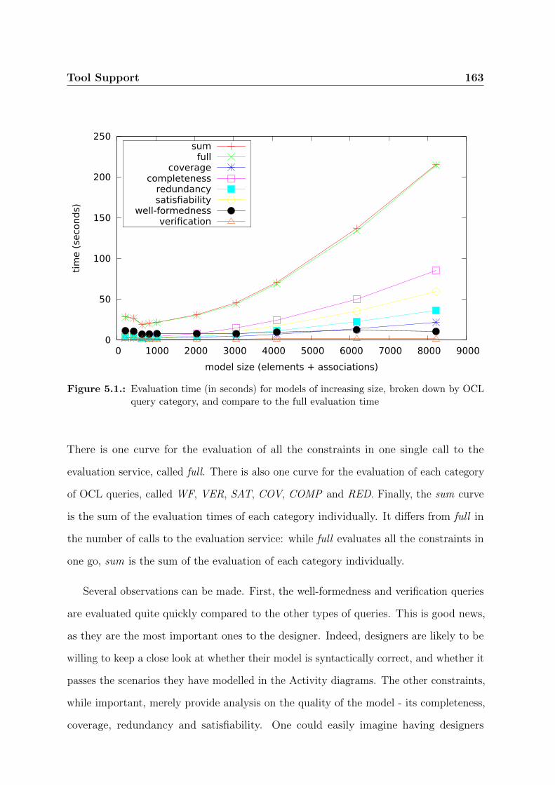
Tool Support 163
0
50
100
150
200
250
0 1000 2000 3000 4000 5000 6000 7000 8000 9000
tim
e (
seco
nd
s)
model size (elements + associations)
sumfull
coveragecompleteness
redundancysatisfiability
well-formednessverification
Figure 5.1.: Evaluation time (in seconds) for models of increasing size, broken down by OCLquery category, and compare to the full evaluation time
There is one curve for the evaluation of all the constraints in one single call to the
evaluation service, called full. There is also one curve for the evaluation of each category
of OCL queries, called WF, VER, SAT, COV, COMP and RED. Finally, the sum curve
is the sum of the evaluation times of each category individually. It differs from full in
the number of calls to the evaluation service: while full evaluates all the constraints in
one go, sum is the sum of the evaluation of each category individually.
Several observations can be made. First, the well-formedness and verification queries
are evaluated quite quickly compared to the other types of queries. This is good news,
as they are the most important ones to the designer. Indeed, designers are likely to be
willing to keep a close look at whether their model is syntactically correct, and whether it
passes the scenarios they have modelled in the Activity diagrams. The other constraints,
while important, merely provide analysis on the quality of the model - its completeness,
coverage, redundancy and satisfiability. One could easily imagine having designers
164 Tool Support
regularly evaluate well-formedness and verification queries on their development platform,
while leaving the other types of constraints to a server, e.g. as part of a continuous
integration process, where the time and memory required for their evaluation is less of a
problem. Another observation to be made is that the overhead cost of evaluating each
type of query separately is almost zero, as one can see by comparing the full and sum
curves.
5.4.2. Correct v. Incorrect Models
The next step was to compare the evaluation of correct and incorrect models. We used
the model generator to generate three types of models: correct models, that do not
raise any errors or warnings for their well-formedness and verification queries; malformed
models, that do raise errors for their well-formedness queries; and incorrect models, that
do not raise any errors or warnings for their well-formedness queries, but that do raise
errors for their verification queries.
To generate malformed models, the model generator assigns roles to activity partitions
that have not been assigned to the corresponding user, breaking one of the well-formedness
queries. To generate incorrect but well-formed models, we simply took correct models,
and changed all the «Forbidden» stereotypes into «Granted» stereotypes, as well as
all the «Granted» stereotypes into «Forbidden» stereotypes. Since the original models
were correct, the actions stereotyped with «Forbidden» were guaranteed to require at
least one permission that was not activated by the user. Since the actions have been
stereotyped with «Granted» instead, this guarantees that the corresponding verification
query fails. Similarly, the actions originally stereotyped with «Granted» were guaranteed
to succeed, and therefore all the required permissions were available to the user. When
the stereotype has been changed to «Forbidden», the verification query fails, since there
are no permissions missing.

Tool Support 165
Table 5.2.: Number of warnings raised in each category for increasingly large correct models
correct 250 500 750 1000 1250 2500 3750 5000 7500 10000
completeness (W) 0 0 0 0 1 1 2 4 5 7
coverage (W) 10 20 32 46 59 122 185 243 365 490
redundancy (W) 0 0 0 0 0 0 0 0 0 0
total (W) 10 20 32 46 60 123 187 247 370 497
In Figure 5.2, we compare, for each type of model, the total evaluation time for a full
evaluation and for an ordered evaluation. While the full evaluation results are similar
across the three graphs, the ordered evaluation times vary. Indeed, on a correct model,
the ordered evaluation will first evaluate the well-formedness constraints. No errors
or warnings will be raised so the verification, coverage, completeness and redundancy
constraints will be evaluated. Since the verification constraints do not produce any errors
or warnings, the satisfiability constraints are not evaluated. The result is an evaluation
time slightly below the full evaluation time, as all types of queries but the satisfiability
queries are evaluated. The incorrect models evaluation is similar to the correct evaluation,
except that, since the verification fails, the satisfiability constraints are evaluated too.
The ordered evaluation time is therefore the same as the full evaluation time. The
malformed models evaluation is quite different. With the ordered evaluation, when the
well-formedness evaluation fails, no other types of queries are evaluated, which leads to a
significant improvement on evaluation time compared to the full evaluation. Therefore,
the ordered evaluation is never slower than the full evaluation, and in some cases, it is
significantly faster.
Table 5.2 shows the number of errors and warnings raised for each size of model,
broken down by OCL query category, for correct models. Tables 5.3 and 5.4 do the same
for malformed and unverified models.
In Table 5.2, we have ignored well-formedness, verification and satisfiability constraints.
Indeed, since the models are correct, they will not raise any errors or warnings in these
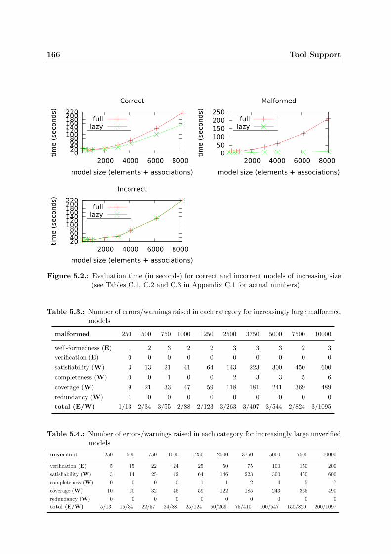
166 Tool Support
0 20 40 60 80 100 120 140 160 180 200 220
2000 4000 6000 8000
tim
e (
seco
nd
s)
model size (elements + associations)
Correct
fulllazy
0 50
100 150 200 250
2000 4000 6000 8000
tim
e (
seco
nd
s)
model size (elements + associations)
Malformed
fulllazy
20 40 60 80
100 120 140 160 180 200 220
2000 4000 6000 8000
tim
e (
seco
nd
s)
model size (elements + associations)
Incorrect
fulllazy
Figure 5.2.: Evaluation time (in seconds) for correct and incorrect models of increasing size(see Tables C.1, C.2 and C.3 in Appendix C.1 for actual numbers)
Table 5.3.: Number of errors/warnings raised in each category for increasingly large malformedmodels
malformed 250 500 750 1000 1250 2500 3750 5000 7500 10000
well-formedness (E) 1 2 3 2 2 3 3 3 2 3
verification (E) 0 0 0 0 0 0 0 0 0 0
satisfiability (W) 3 13 21 41 64 143 223 300 450 600
completeness (W) 0 0 1 0 0 2 3 3 5 6
coverage (W) 9 21 33 47 59 118 181 241 369 489
redundancy (W) 1 0 0 0 0 0 0 0 0 0
total (E/W) 1/13 2/34 3/55 2/88 2/123 3/263 3/407 3/544 2/824 3/1095
Table 5.4.: Number of errors/warnings raised in each category for increasingly large unverifiedmodels
unverified 250 500 750 1000 1250 2500 3750 5000 7500 10000
verification (E) 5 15 22 24 25 50 75 100 150 200
satisfiability (W) 3 14 25 42 64 146 223 300 450 600
completeness (W) 0 0 0 0 1 1 2 4 5 7
coverage (W) 10 20 32 46 59 122 185 243 365 490
redundancy (W) 0 0 0 0 0 0 0 0 0 0
total (E/W) 5/13 15/34 22/57 24/88 25/124 50/269 75/410 100/547 150/820 200/1097
Tool Support 167
categories. For the same reason, we ignored the well-formedness category in Table 5.4,
since the models are well-formed.
It is quite clear that, even on relatively small models, the number of errors, and
especially the number of warnings, goes up very quickly. This is partly due to the fact
that the models are generated randomly, as we have discussed earlier.
5.4.3. Discussion
It appeared from the above evaluation that evaluating the entire set of rbacUML OCL
queries has a more-than-linear complexity with regard to the size of the model, and
that the number of errors and warnings produced grows quickly too. Breaking down
the evaluation into each category highlighted the fact that the well-formedness and
verification queries are faster to evaluate than the other types, which is good news for
the designers using rbacUML, as they are likely the two types of OCL queries they want
to evaluate most often. Finally, ordered and selective evaluation strategies can be used
separately or together to further decrease the worse-case evaluation time and reduce
the amount of meaningless and/or uninteresting warnings and errors raised. Indeed, as
one can see in Tables 5.2, 5.3 and 5.4, if some categories are not evaluated because the
user has chosen not to evaluate them or because of the ordered evaluation strategy, the
number of errors and warnings produced will be lower, and concentrated only on those
categories that are of interest for the designer.
5.5. Fixing Performance
An analysis of the performance of the solution proposed in Chapter 4 for fixing incorrect
models is done in this section. The evaluation is performed from three distinct angles:

168 Tool Support
the comparison of the constraint selection criteria, the comparison of the tree traversal
strategies, and the assessment of the effect of the NoChangeRbacDSML profile. In its current
state, the fixing algorithm does not scale very well. Indeed, for each node it creates,
the entire model needs to be re-evaluated. Future work is discussed in the conclusion
to improve the algorithm’s efficiency. As a consequence, we have only evaluated it on
relatively small models.
Four models are used to perform the evaluation.
The first one is the students’ marks system that has been used in the previous chapters.
To make it incorrect, the role hierarchy between the role Professor and the role Student
has been removed, leading to the model represented in Figure 5.3. The model validation
raises one error, a violation of the Granted constraint on the Smith_Create Marks
element.
The second model is a larger model, created for the very purpose of this evaluation.
It is made of 10 users, 3 roles, 15 permissions, 15 resources, 5 Granted scenarios and 5
Forbidden scenarios, for a total of 53 elements. It raises 6 errors: 5 on Granted scenarios,
and 1 on a Forbidden scenario.
The third model is a modified version of the second one, with only one error, on a
Forbidden scenario.
The fourth model is also a modified version of the second one, with one error on a
Forbidden scenario, and one error on a Granted scenario.
To make sure that the algorithm eventually stops, a tree depth limit has been set
to 20 for all models. It was necessary to have a tree depth at least as large as the
number of errors on each model, to increase the chances of finding perfect solutions. Still,
the evaluation sometimes takes a very, very long time, so two additional termination
constraints were introduces: only the first five solutions are returned, and if they have not
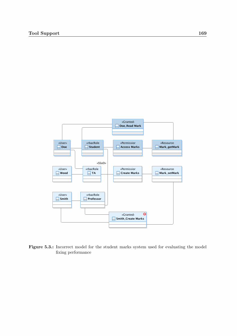
Tool Support 169
Figure 5.3.: Incorrect model for the student marks system used for evaluating the modelfixing performance

170 Tool Support
been found within 30 minutes, the evaluation is stopped. Furthermore, each evaluation
was carried out three times and the lowest values were selected, to account for differences
caused by the OS process scheduler or other services and software running on the testing
machine. The evaluation was carried out using the same machine as for the rbacUML
evaluation performance study.
It has been argued in Chapter 4 that designers are likely to be more interested
in solutions that are closer to the original model, i.e. solutions that minimise the
changes made to the model. A function scost(x) has been defined that computes
the cost of a solution as the sum of the costs of each fix that constitute the solution:
scost(S) =∑
fcost(fixi),∀fixi ∈ S, where S represents a solution, which is a list of fixes.
The cost of a fix, as discussed in Chapter 4, can be computed in various ways depending
on the designer’s preference and the specificities of the DSML considered. For this study,
it is important to try to be as precise as possible while still being general enough for the
results to apply broadly. The following function is proposed with an aim to generate a cost
that is simple to compute and relevant to rbacDSML: fcost(F ) =∑
ccost(c1),∀ci ∈ F ,
where F is a fix, or a set of changes. The cost of changes is then defined as follows:
ccost(c) = 1 if the change is the atomic addition or deletion of an association, and
ccost(c) = 2 if the change is the atomic addition of a new element. In rbacDSML, elements
are never deleted, so there is no need to define a cost for that operation.
The rationale behind the difference in cost between the addition/deletion of an
association and the addition of an element stems from the very nature of rbacDSML: it
is indeed reasonable to expect that, in an organisation, the creation of a new role or a
new permission is a decision that is less likely to happen (the organisation’s structure
presumably changes less often than its members and their position in the structure),
and that is taken much more seriously, than the addition or deletion of a particular
assignment. Indeed, as roles are supposed to match the organisation’s structure, the
Tool Support 171
addition of a new role would mean a modification of the company’s structure, a decision
unlikely to be made by a single designer in order to get rid of an annoying violation of
an OCL constraint.
5.5.1. OCL Constraint Selection
Evaluation Criteria
In every node in the solution tree that has a model that violates several instances of
the OCL constraints, a choice must be made over which instance of which constraint to
fix. In Section 4.5.1 it is argued that an ordering of the selection of the next error to fix
based on the categories of the OCL constraints will lead to fewer unnecessary branches
to be considered.
The evaluation performed here compares three constraint selection strategies. The
first one will evaluate the Granted constraints first, then Forbidden, roles activation,
DSoD and finally SSoD. The second one is the opposite, i.e. SSoD first, followed by DSoD,
roles activation, Forbidden, and finally Granted. The third one follows the categories
order, i.e. the SSoD, DSoD and role activation constraints first (in no particular order),
then Granted and Forbidden (in no particular order). When the name of the violated
constraint is not enough to select an error to fix, the lexicographic order over the context’s
name is used.
Results
The results of the evaluation on model 2 are summarised on Table 5.5. Model 2 was
chosen for its large number of errors, highlighting the importance of carefully selecting
which error to fix first.
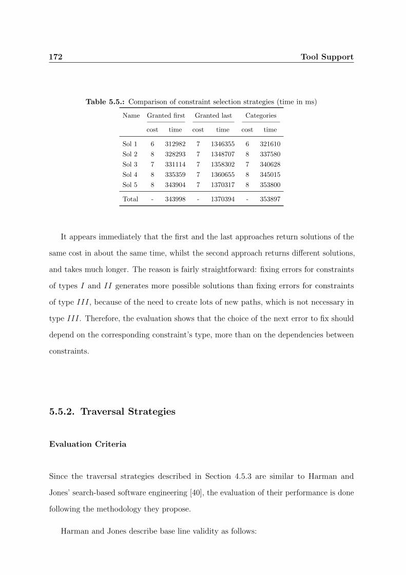
172 Tool Support
Table 5.5.: Comparison of constraint selection strategies (time in ms)
Name Granted first Granted last Categories
cost time cost time cost time
Sol 1 6 312982 7 1346355 6 321610
Sol 2 8 328293 7 1348707 8 337580
Sol 3 7 331114 7 1358302 7 340628
Sol 4 8 335359 7 1360655 8 345015
Sol 5 8 343904 7 1370317 8 353800
Total - 343998 - 1370394 - 353897
It appears immediately that the first and the last approaches return solutions of the
same cost in about the same time, whilst the second approach returns different solutions,
and takes much longer. The reason is fairly straightforward: fixing errors for constraints
of types I and II generates more possible solutions than fixing errors for constraints
of type III, because of the need to create lots of new paths, which is not necessary in
type III. Therefore, the evaluation shows that the choice of the next error to fix should
depend on the corresponding constraint’s type, more than on the dependencies between
constraints.
5.5.2. Traversal Strategies
Evaluation Criteria
Since the traversal strategies described in Section 4.5.3 are similar to Harman and
Jones’ search-based software engineering [40], the evaluation of their performance is done
following the methodology they propose.
Harman and Jones describe base line validity as follows:
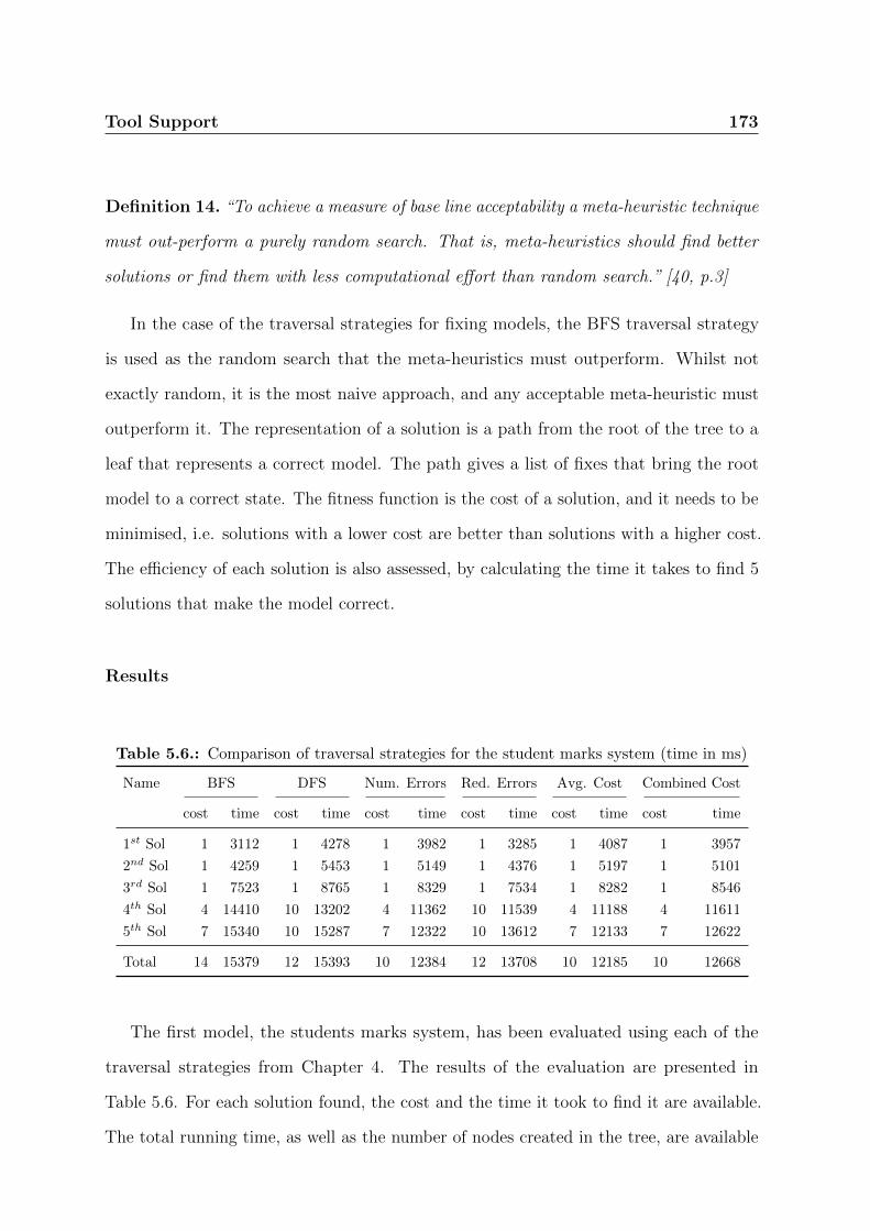
Tool Support 173
Definition 14. “To achieve a measure of base line acceptability a meta-heuristic technique
must out-perform a purely random search. That is, meta-heuristics should find better
solutions or find them with less computational effort than random search.” [40, p.3]
In the case of the traversal strategies for fixing models, the BFS traversal strategy
is used as the random search that the meta-heuristics must outperform. Whilst not
exactly random, it is the most naive approach, and any acceptable meta-heuristic must
outperform it. The representation of a solution is a path from the root of the tree to a
leaf that represents a correct model. The path gives a list of fixes that bring the root
model to a correct state. The fitness function is the cost of a solution, and it needs to be
minimised, i.e. solutions with a lower cost are better than solutions with a higher cost.
The efficiency of each solution is also assessed, by calculating the time it takes to find 5
solutions that make the model correct.
Results
Table 5.6.: Comparison of traversal strategies for the student marks system (time in ms)
Name BFS DFS Num. Errors Red. Errors Avg. Cost Combined Cost
cost time cost time cost time cost time cost time cost time
1st Sol 1 3112 1 4278 1 3982 1 3285 1 4087 1 3957
2nd Sol 1 4259 1 5453 1 5149 1 4376 1 5197 1 5101
3rd Sol 1 7523 1 8765 1 8329 1 7534 1 8282 1 8546
4th Sol 4 14410 10 13202 4 11362 10 11539 4 11188 4 11611
5th Sol 7 15340 10 15287 7 12322 10 13612 7 12133 7 12622
Total 14 15379 12 15393 10 12384 12 13708 10 12185 10 12668
The first model, the students marks system, has been evaluated using each of the
traversal strategies from Chapter 4. The results of the evaluation are presented in
Table 5.6. For each solution found, the cost and the time it took to find it are available.
The total running time, as well as the number of nodes created in the tree, are available

174 Tool Support
at the bottom of the table. Each and every strategy managed to produce 5 solutions
within about 15 seconds. In fact, looking at the total line at the bottom of the table, it
comes immediately that all the strategies except DFS did complete faster than BFS, and
they all did so using less nodes than BFS. This would be particularly important with
larger models, as each node requires the evaluation of the model, which can be long.
Looking at individual solutions shows a more mixed picture: no strategy could beat
BFS for the time to reach the first solution, but they catch up later. Moreover, both the
DFS and the reduction of errors strategies did produce solutions that are less fit than
BFS.
Table 5.7.: Comparison of traversal strategies for a large model (time in ms)
Name Num. Errors Avg. Cost
cost time cost time
1st Sol 12 311133 6 321610
2nd Sol 12 312498 8 337580
3rd Sol 12 313840 7 340628
4th Sol 12 315217 8 345015
5th Sol 12 316582 8 353800
nodes time nodes time
Total 234 316778 254 353897
The evaluation of the second model is summarised in Table 5.7. The table is smaller,
because most of the strategies failed to produce 5 solutions in less than 30 minutes. In
fact, the BFS strategy was left running for over 12 hours and still did not manage to
produce 5 solutions. This, of course, highlights the need for carefully chosen strategies.
The only two strategies to return solutions in under 30 minutes were the number of errors
strategy and the average cost strategy. They returned solutions in less than 6 minutes.

Tool Support 175
As one can see from the table, the average cost strategy did find fitter solutions, but
it took a bit longer, and used a few more nodes than the number of errors strategy, which
was also faster at finding a first solution.
Table 5.8.: Comparison of traversal strategies for the third model (time in ms)
Name BFS DFS Num. Errors Red. Errors Avg. Cost Combined Cost
cost time cost time cost time cost time cost time cost time
1st Sol 1 7891 1 7884 1 8399 1 8222 1 7981 1 8059
2nd Sol 2 13597 2 13657 2 14457 2 14317 2 13668 2 13873
3rd Sol 2 16609 2 16388 2 17199 2 17137 2 16751 2 16658
4th Sol 2 19489 2 19170 2 19966 2 19912 2 19626 2 19313
5th Sol 3 23956 3 23356 3 24110 3 24059 3 24069 3 23413
Total 15 23996 15 23412 15 24146 15 24100 15 24111 15 23452
The evaluation of the third model is summarised in Table 5.8. It is very interesting
to notice that all strategies perform almost the same. In fact, the differences between
them are so small that they cannot be ranked. This is due to the fact that they did not
have to be used at all, as at least five solutions were generated with just one fix.
Table 5.9.: Comparison of traversal strategies for the fourth model (time in ms)
Name BFS Num. Errors Red. Errors Avg. Cost Combined Cost
cost time cost time cost time cost time cost time
1st Sol 3 171210 3 150511 3 153819 2 272244 2 157088
2nd Sol 4 176641 4 155599 4 158778 4 292412 4 171545
3rd Sol 4 179404 4 158122 4 161296 3 296023 3 174161
4th Sol 4 182140 4 160693 4 163830 4 301794 4 178125
5th Sol 5 186437 5 164599 5 167715 4 313282 4 186124
Total 123 186491 123 164656 123 167812 134 313922 134 186161
The evaluation of the fourth model is summarised in Table 5.9. Compared to the
previous model, one immediately notices that the strategies produce less similar results.
Indeed, both the average cost and the combined cost strategies produce fitter solutions,

176 Tool Support
even though the other strategies all produce equally fit solutions. The time information
is more interesting: indeed, the reduction of errors and number of errors perform better
than BFS, while the combined cost strategy performs similarly to BFS, and average cost
performs much worse. DFS did not terminate on time, hence it is not included in the
table.
Summary
The comparison of the traversal strategies did not highlight one particular strategy as
performing consistently better than the other ones, either in terms of time or in terms of
the order in which solutions are found. These conflicting results seem to indicate that
the choice of one strategy over another may depend on some properties of the incorrect
model, such as the number of errors or their type, for example. The validation of this
hypothesis would require a deeper evaluation, using larger models. This can only be done
once the fixing algorithm’s scalability has been addressed.
5.5.3. The NoChangeRbacDSML extension of the rbacDSML Profile
Evaluation Criteria
The last evaluation criteria in this section is the use of the NoChangeRbacDSML profile.
The profile is described and discussed in Chapter 3, Section 4.5.2, and allows designers
to make sure that any solution proposed will not delete some associations or add some
element, according to the designer’s annotations on a model.
Here the time it takes to generate 5 acceptable solutions is measured, according
to three scenarios: the first one is a model without any NoChangeRbacDSML stereotype
applied; the second one is a model where the policy, i.e. the assignment of permissions to

Tool Support 177
resources, cannot be modified; the third one is a model where the scenarios cannot be
modified.
Results
Table 5.10.: Effect of the NoChangeRbacDSML stereotype on the student marks system (timein ms)
Solution No NoChangeRbacDSML Policy Scenarios
cost time cost time cost time
Sol 1 1 4087 1 3242 1 3111
Sol 2 1 5197 1 6501 1 6453
Sol 3 1 8282 4 9786 - -
Sol 4 4 11188 6 10807 - -
Sol 5 7 12133 7 16986 - -
nodes time nodes time nodes time
Total 10 12185 15 17112 6 7815
The first model to be evaluated was the student marks system, as summarised in
Table 5.10. One immediately notices that the third test, where scenarios cannot change,
only produces two solutions, and finishes much faster than the other two tests. Indeed,
all other solutions that exist involve at least one change to the associations attached to a
scenario, and are therefore forbidden.
It is also worth noting that the second test, where the policy does not change, takes
longer to generate solutions than the first test, which does not use the NoChangeRbacDSML
profile. One could also claim that the second test’s solutions are less fit than the first
test’s, but one must keep in mind that, in the second test, the designer has specifically
indicated that he is not interested in certain solutions. Therefore, he gets 5 potentially
interesting solutions, instead of having to discard a number of them immediately after
test 1, since they do not conform to his requirements.
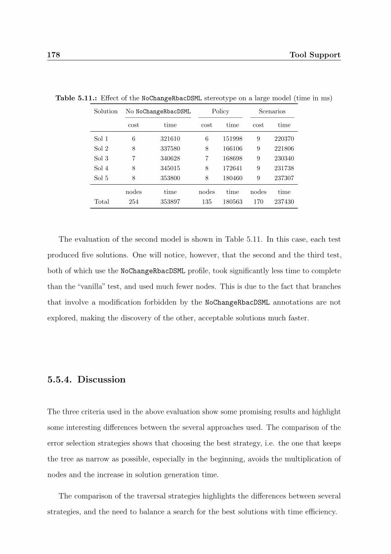
178 Tool Support
Table 5.11.: Effect of the NoChangeRbacDSML stereotype on a large model (time in ms)
Solution No NoChangeRbacDSML Policy Scenarios
cost time cost time cost time
Sol 1 6 321610 6 151998 9 220370
Sol 2 8 337580 8 166106 9 221806
Sol 3 7 340628 7 168698 9 230340
Sol 4 8 345015 8 172641 9 231738
Sol 5 8 353800 8 180460 9 237307
nodes time nodes time nodes time
Total 254 353897 135 180563 170 237430
The evaluation of the second model is shown in Table 5.11. In this case, each test
produced five solutions. One will notice, however, that the second and the third test,
both of which use the NoChangeRbacDSML profile, took significantly less time to complete
than the “vanilla” test, and used much fewer nodes. This is due to the fact that branches
that involve a modification forbidden by the NoChangeRbacDSML annotations are not
explored, making the discovery of the other, acceptable solutions much faster.
5.5.4. Discussion
The three criteria used in the above evaluation show some promising results and highlight
some interesting differences between the several approaches used. The comparison of the
error selection strategies shows that choosing the best strategy, i.e. the one that keeps
the tree as narrow as possible, especially in the beginning, avoids the multiplication of
nodes and the increase in solution generation time.
The comparison of the traversal strategies highlights the differences between several
strategies, and the need to balance a search for the best solutions with time efficiency.
Tool Support 179
The study of the NoChangeRbacDSML profile then shows that using the profile not only
ignores useless results for the designer, but may also dramatically speed up the solution
discovery time.
Perhaps the biggest weakness of this evaluation is the small number of models
considered. However, even with this small number of models, the evaluation has shown
that a solution adapted for one model might not be adapted for another, hence it is
probably impossible to draw conclusions that would apply to all rbacDSML models, let
alone all models of any DSML, even with a large number of models considered. The
evaluation indicates that expert knowledge will be required to select the most appropriate
settings for a particular model, if one needs solutions to be generated relatively quickly.
The evaluation has also shown that the more errors there are on a model, the longer the
generation of solutions takes. Hence, one would recommend that designers evaluate their
models frequently, in order to take remedial actions as soon as possible. This further
stresses the need for improvements in the evaluation speed.
Finally, it is worth pointing out that the plug-in was by no means optimised, and
should indeed be treated as an early product rather than a stable and optimised solution.
The generation time, especially on large models with lots of errors, would greatly benefit
from optimisations that reduce the number of nodes to consider, and from optimisation
that reduce the evaluation time of models. Egyed’s approach for incremental evaluation
of models [28] could possibly bring massive time savings here.
5.6. A Real-Life Case Study
We illustrate the utility of rbacUML with a real example, the cloud-based repository
hosting service chiselapp.com. ChiselApp is a server-side PHP program that allows
software developers to host and share projects using the Fossil distributed version

180 Tool Support
control system. There are two layers of access controls: at the account layer, the PHP
program manages the authentication of developers through a set of roles for the website;
at the repository layer, the built-in web subsystem of Fossil manages the access to the
repositories through a database table inside the Fossil repository.
The account-managed repositories are classified into private and public. The public
repositories are openly accessible to any visitor of the website. The private repositories
are only exposed to the account owners. Without logging into chiselapp.com, even
the owner cannot access these private repositories. Because the Fossil repositories are
distributed, once granted access by the owner, the repository-level access control allows
additional guests, committers or administrators to pull, sync, edit or even delete the
repository.
In order to verify the RBAC properties of a system that does not provide its design
in UML, we applied the reverse engineering toolkit PHP_UML 1 to recover the deployment
view of the system from the source code (Figure 5.4). Notice that PHP programs are
not purely object-oriented, some of the high-level functions in the .php artefacts are not
necessarily encapsulated by PHP classes. Therefore, pseudo UML classes with a single
operation are created to represent those functions. The recovered XMI model provides
the traceability links between the low-level PHP classes and the high-level .php artefacts,
which are not shown here for clarity.
According to the implementation, we modelled the access control configuration as
shown in Figure 5.5. In this diagram, we identify three typical users Alice, Bob, and
Charles and associate them with representative roles such as Account Guest, Account
Owner, Site Admin for the account management, and Repository Guest, Repository
Committer, and Repository Owner for the repository management. The relations between
these roles indicate the inheritance of permissions from the parent roles.
1http://pear.php.net/package/PHP UML
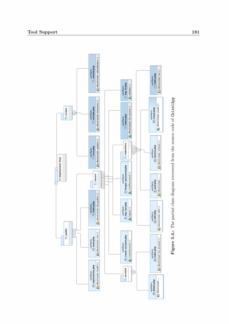
Tool Support 181
Fig
ure
5.4
.:T
he
par
tial
clas
sdia
gram
reco
vere
dfr
omth
eso
urc
eco
de
ofChiselApp

182 Tool Support
Figure 5.5.: Concepts of users, roles, and permissions are instantiated as an access controlclass diagram.
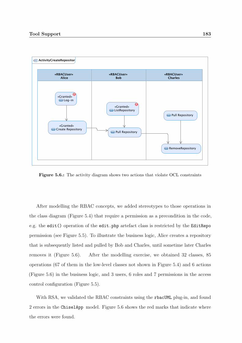
Tool Support 183
Figure 5.6.: The activity diagram shows two actions that violate OCL constraints
After modelling the RBAC concepts, we added stereotypes to those operations in
the class diagram (Figure 5.4) that require a permission as a precondition in the code,
e.g. the edit() operation of the edit.php artefact class is restricted by the EditRepo
permission (see Figure 5.5). To illustrate the business logic, Alice creates a repository
that is subsequently listed and pulled by Bob and Charles, until sometime later Charles
removes it (Figure 5.6). After the modelling exercise, we obtained 32 classes, 85
operations (67 of them in the low-level classes not shown in Figure 5.4) and 6 actions
(Figure 5.6) in the business logic, and 3 users, 6 roles and 7 permissions in the access
control configuration (Figure 5.5).
With RSA, we validated the RBAC constraints using the rbacUML plug-in, and found
2 errors in the ChiselApp model. Figure 5.6 shows the red marks that indicate where
the errors were found.
184 Tool Support
First, the Login action was marked as restricted by the permission of ListRepo.
However, the PHP implementation never checks such a permission. It was our misun-
derstanding as modellers when creating the activity diagram that the login needs to be
protected. Indeed, every user of ChiselApp is allowed to login by the business logic of
the PHP program. Therefore, rbacUML found an error in the manually annotated model
that wrongly represents the implementation in the code.
Second, Bob was not allowed to edit the repository, even though he has been assigned
as the owner of the repository. This is a more remarkable error. In the access control
configuration diagram, Bob has the role Repository Committer with the permission
EditRepos. In the Activity diagram corresponding to the program execution at runtime,
however, this role was not activated. Therefore, it is important to check whether Bob is
the committer to allow him to edit the repository. The implementation of ChiselApp
delegates such a check to the Fossil toolkit. However, one can construct a test scenario
whereby Bob is the AccountOwner but not a RepositoryCommitter. Using this test case,
we have demonstrated that ChiselApp should not delegate the verification to the other
tool, otherwise there is an inconsistency in the access control configuration. In other
words, this is confirmed as a bug in the original implementation of ChiselApp. The bug
had already been reported on the ChiselApp issue tracking system, but the maintainer
argued that the bug is, in fact, a feature. We disagree with the maintainer’s opinion,
because the default settings for new users violate the access control property we verified.
In brief, modelling the access control properties of a real-life cloud-based repository
hosting service showed that rbacUML can be useful to fix design issues even after the
implementation has been done. It requires some reverse engineering effort, but the cost
is justified if security errors are found.

Tool Support 185
5.6.1. Lessons Learned
The ChiselApp case study was our first try at using rbacUML on a real application. We
learned valuable lessons during the process, and were able to identify a few aspects of
rbacUML that could be improved.
Recovering the class diagram for ChiselApp was very easy, thanks to PHP_UML.
Recovering the activity diagram was however more complex, as it required manual
inspection of the code. It may be a good idea to investigate how to automate the process,
at least partially.
Another issue that we encountered has to do with UML itself: as soon as a UML
model grows to a realistic size, it becomes very difficult to navigate in its diagram form.
The tree form provided by RSA’s model explorer often proved a more practical solution.
We think that the ability to select at runtime which elements to include in a diagram
may help the navigation of large models.
On the positive side, once we had found the issue, the graphical representation makes
it very easy to visualise. The ability to tweak the model and re-verify it after making a
few changes was also very useful to explore the possible ways to solve the error.

186

Chapter 6.
Conclusions
187

188 Conclusions
In this dissertation, we have proposed a new Model-Driven Engineering approach
for modelling, analysing and fixing RBAC concerns by extending UML models. The
proposed approach comprises a DSML as well as a DSMAL, allowing stakeholders to
select the most appropriate language for the specific activities they want to perform. The
contributions build and improve on existing approaches on several points.
Our approach is general because it has been designed using the standard UML exten-
sion mechanisms: stereotypes, associations and OCL queries. This allows designers,
on the one hand, to adopt the approach with having to learn new languages, tools
or methodologies, if they are already familiar with UML; and on the other hand
to port our approach to other UML tools if necessary. While our approach was
implemented as plug-ins for IBM Rational Software Architect, we have provided all
the necessary information to port it to any other modelling tool that supports the
UML standard, its extension mechanism, and OCL queries evaluation.
Our approach is systematic because it is centred on two UML profiles that define a
Domain-Specific Modelling Annotations Language (DSMAL) as well as a Domain-
Specific Modelling Language (DSML), which have been developed following Selic’s
guidelines for systematic DSML development [95].
Our approach does not require stakeholders to write code or queries themselves be-
cause the queries have already been defined as part of the two profiles. However,
should they want to expand the profiles’ capabilities or even run model-level queries,
they have the possibility to do so.
The rbacUML provides a general categorisation of OCL queries to better understand
the different types of analyses that can be run on models created using DSMALs or
DSMLs.

Conclusions 189
Strategies for reducing the analysis time were developed on the basis of a proposed
categorisation of OCL queries and the dependencies identified between them. An
evaluation of those strategies has found them to be effective.
An integration with organisational repositories is considered through the LDIF im-
port filter from existing user directories.
rbacDSML models can be automatically fixed when one or several errors are detected.
The set of generated solutions is both correct and, under some assumptions, complete.
6.1. Future Work
The work presented in this dissertation can be extended in several area, as discussed
below, to improve designers’ experience when dealing with domain-specific concerns, and
access control in particular.
6.1.1. Transformations
Both representations are derived from the same domain meta-model. Since the choice
of profile to use depends on the circumstances, designers need transformations from
one profile to the other, and back. It must be possible to reflect changes made to one
representation on the other one, in order to keep both models synchronised. Since
changes could happen in both representations, it is important to define a bidirectional
transformation that would allow designers to transform a DSMAL model into a DSML,
and back. Since the DSML contains a subset of the information contained in the DSMAL,
tools such as GRoundTram [41] allow one to define a transformation from the DSMAL
to the DSML, and the transformation from the DSML back to the DSMAL comes “for
free”. If both models can change before being synchronised, then the problem is similar

190 Conclusions
to model-code synchronisation problems that MDE approaches face [114]. A similar
approach to what is needed in this case is Guerra and de Lara’s use of triple graph
transformations to derive views from models [38]. However, their views are not editable.
The Problem with DSMALs
The transformations called for in this dissertation differ from transformations between
“ad-hoc” DSMLs and DSMLs implemented as UML profiles, such as those described by
Wimmer [113]. The latter are produced semi-automatically. Wimmer assumes that a
transformation can “destroy” the target model and entirely replace it with the newly
generated model. This is a fair assumption when dealing with DSMLs only, as there is no
more information in one representation than in the other. But in the case of a DSMAL,
such an approach will destroy all the information in the model that is not related to
the DSML. In the example in Chapter 3, a destructive approach would completely erase
the Student, Module, Professor and TA classes, as well as the Mark::getDate() and
Mark::setDate() operations, in the class diagram (Chapter 3, Figure 3.7a) alone. This
problem would not occur with bidirectional transformations defined with GRoundTram,
as it keeps track of the information that was removed during the forward transformation
between the DSMAL and the DSML.
Yet, Wimmer’s approach can still partially apply here, especially his discussion of
the mapping between both languages. Since both languages stem from the same domain
meta-model, it is likely that many concepts will have a one-to-one mapping. However,
the necessary redundancy in the DSMAL means that some mappings will be one-to-many,
which further complicates the creation of the transformation.
Conclusions 191
Multiple Profiles
Annotating UML models with concepts from one domain is already challenging, but what
if one wants to annotate it with concepts from several domains? There may be many
interesting ways of using DSMLs to model some aspects of the software: RBAC is one of
them, but there are others, such as performance, specific business rules, persistence, etc.
It would make sense to have a DSML as well as a DSMAL for each of them. The same
general-purpose model could then be annotated with stereotypes from several profiles,
which brings new challenges to keep the general-purpose model and the DSMLs in sync,
and to prevent conflicts from happening.
If the same general-purpose model is annotated with concepts from several profiles,
there is a chance that synchronisation problems will occur. Indeed, if a model is annotated
with both access control and performance annotations, and changes are done concurrently
to their respective DSML views, then the transformation that reflects these changes
back to the general-purpose model will be more difficult. This problem is similar to the
model-code synchronisation problem typically encountered in MDE [114].
It is possible that two DSMALs will bring conflicting annotations, and therefore a
mechanism will be necessary to detect them. For example, let’s assume two DSMALs,
one for performance and one for persistence. If a particular element is marked with a
performance requirement, and then marked with a persistence stereotype that involves
saving the element’s state in a database, the persistence will have a negative effect on
the performance. These potential conflicts between stereotypes will have to be identified
on a case by case basis. OCL constraints could be used to detect potential conflict and
bring them to the designer’s attention.
Mussbacher et al’s work [69] addresses this problem of detecting interactions between
different aspects. Their approach captures aspects as UML sequence diagrams and Aspect-

192 Conclusions
oriented Use Case Maps (AoUCM). Domain-specific annotations as well as influence
models are then used to automatically analyse how different aspects influence each other.
Several case studies have already been considered, but it would be very interesting to
study how their approach applies to rbacUML and rbacDSML.
6.1.2. Translating OCL Constraints
In Chapter 3, we have defined OCL constraints for both rbacUML and rbacDSML. Since
the same domain-level properties need to be guaranteed, it is reasonable to expect that
one could create their OCL constraints on the DSML, which is the simplest model and
therefore requires relatively simple constraints, and have them translated to be used with
the DSMAL. After all, there is already a mapping between the concepts in the DSML
and the concepts in the DSMAL.
However, the redundancy and the division of one concept into several ones will make
this process more difficult. Not only is it necessary to create new OCL constraints
to ensure consistency between redundant and spread out concepts, but the existing
constraints may also have to take those into account, which would make them even more
complex. An automated conversion process that would, given both profiles, the mapping
of concepts from one to the other, and the OCL constraints for the DSML, produce the
OCL constraints for the DSMAL, would be incredibly useful, as it would save time and
reduce the occurrence of errors from the manual translation process. With GRoundTram,
one could do this automatic conversion by giving a filter- promotion transformation for
the transformation language UnQL+ [42]. Let T be the mapping from DSMAL to DSML
in UnQL+ and C be a constraint on DSML. The filter promotion transformation is to
transform filter C ◦ T to T ◦ filter C ′ to promote the condition C on the output of T to
a new condition C ′ on the input.
Conclusions 193
In rbacUML, there is a one-to-one mapping for most concepts, which is relatively
obvious from the two extensions of the UML meta-model. Three concepts, however,
require a one-to-many mapping: the user, represented in the DSMAL by one class in
the access control diagram and by any number of partitions in activity diagrams; the
resources, represented in the DSMAL by an operation in a class diagram, and by any
number of messages in a sequence diagram; the role activation, spread in the DSMAL as
«ActivateRoles» and «DeactivateRoles» on scenarios, and over partitions.
This makes translating the OCL constraints from the DSML to the DSMAL quite
difficult. For example, the split of the user concept into several elements means that
a new constraint must be introduced to make sure that all user annotations that are
supposed to represent the same user are consistent, i.e. they must have the same name.
This also makes the OCL constraint that checks that roles activated by a user are also
assigned to him more complicated. In the DSML, the constraint looks like:
context rbacDSML::Scenario inv:
self.user.rbacRole
->includesAll(self.rbacRole)
but in the DSMAL, it looks like:
context rbacUML::Granted inv:
self.base_Action.inPartition
.extension_RBACUser.aliasUser.rBACRole
->includesAll(self.rBACRole)
Because of the separation of the user in two concepts, another OCL constraint is also
necessary to ensure well-formedness:

194 Conclusions
context rbacUML::User inv:
(self.base_Partition <> null)
implies (self.name = self.user.name)
6.1.3. Support for other Access Control Models
In this dissertation, the proposed access control approach is limited to RBAC. As shown
in Chapter 2, it made sense because numerous access control models are built on top of
RBAC, such as OrBAC or GEO-RBAC. Even ABAC is a superset of RBAC. Each of
these access control models brings new challenges that may be addressed by extending
the rbacUML and rbacDSML profiles. In particular, ABAC models will make profile design
as well as modelling much more challenging, if one wants to keep true to our commitment
to provide an easy to use approach: the fact that any attribute could be used will make
it difficult, if not impossible, to manually write meta-model-level OCL constraints that
work for all models. Alternative solutions will probably have to be explored in order to
allow users to model ABAC concepts without writing any code or queries.

Bibliography
[1] AGG: The attributed graph grammar system. http://http://user.cs.tu-
berlin.de/ gragra/agg/ (Last accessed June 2010).
[2] Capability Maturity Model Integration (CMMI). http://www.sei.cmu.edu/cmmi/
(Last accessed Jan 2012).
[3] UMLsec tool, 2001-2010. http://ls14-www.cs.tu-dortmund.de/main2/jj/umlsectool
(Last accessed May 2010).
[4] rbacUML tool, 2009-2013. http://computing-research.open.ac.uk/rbac/ (Last up-
dated May 2013).
[5] Ahn, G.-J., and Shin, M. E. Role-Based Authorization Constraints Specification
Using Object Constraint Language. In Proceedings of the 10th IEEE International
Workshops on Enabling Technologies: Infrastructure for Collaborative Enterprises
(2001), WETICE ’01, IEEE Computer Society, pp. 157–162.
[6] Bandara, A. K., Lupu, E. C., and Russo, A. Using event calculus to formalise
policy specification and analysis. In Proceedings of the 4th IEEE International
Workshop on Policies for Distributed Systems and Networks (2003), POLICY ’03,
IEEE Computer Society, pp. 26–.
[7] Basin, D., Clavel, M., Doser, J., and Egea, M. Automated analysis of
195

196 Bibliography
security-design models. Information and Software Technology 51, 5 (2009), 815 –
831. SPECIAL ISSUE: Model-Driven Development for Secure Information Systems.
[8] Basin, D., Clavel, M., and Egea, M. A decade of model-driven security. In
Proceedings of the 16th ACM symposium on Access control models and technologies
(2011), SACMAT ’11, ACM, pp. 1–10.
[9] Basin, D., Clavel, M., Egea, M., and Schlapfer, M. Automatic generation
of smart, security-aware gui models. In Engineering Secure Software and Systems,
vol. 5965 of Lecture Notes in Computer Science. Springer, 2010, pp. 201–217.
[10] Basin, D., Doser, J., and Lodderstedt, T. Model driven security: From
UML models to access control infrastructures. ACM Trans. Softw. Eng. Methodol.
15, 1 (Jan. 2006), 39–91.
[11] Bell, D. E., and La Padula, L. J. Secure computer system: Unified exposition
and multics interpretation. Tech. rep., DTIC Document, 1976.
[12] Bergmann, G., Boronat, A., Heckel, R., Torrini, P., Rath, I., and
Varro, D. Advances in model transformations by graph transformation: Specifica-
tion, execution and analysis. In Rigorous Software Engineering for Service-Oriented
Systems, vol. 6582 of Lecture Notes in Computer Science. Springer, 2011, pp. 561–
584.
[13] Bezivin, J. In search of a basic principle for model driven engineering. UPGRADE
- The European Journal for the Informatics Professional V, 2 (2004), 21–24.
[14] Bezivin, J., Jouault, F., and Touzet, D. Principles, standards and tools for
model engineering. In Proceedings of the 10th IEEE International Conference on
Engineering of Complex Computer Systems (2005), ICECCS ’05, IEEE Computer
Society, pp. 28–29.

Bibliography 197
[15] Blanc, X., Mougenot, A., Mounier, I., and Mens, T. Incremental detection
of model inconsistencies based on model operations. In CAiSE ’09: Proceedings of
the 21st International Conference on Advanced Information Systems Engineering
(2009), Springer-Verlag, pp. 32–46.
[16] Blanc, X., Mounier, I., Mougenot, A., and Mens, T. Detecting model
inconsistency through operation-based model construction. In ICSE ’08: Proceed-
ings of the 30th international conference on Software engineering (2008), ACM,
pp. 511–520.
[17] Burmester, S., Giese, H., Niere, J., Tichy, M., Wadsack, J. P., Wagner,
R., Wendehals, L., and Zundorf, A. Tool integration at the meta-model
level: the fujaba approach. International Journal on Software Tools for Technology
Transfer 6, 3 (2004), 203–218.
[18] Bezivin, J., Buttner, F., Gogolla, M., Jouault, F., Kurtev, I., and
Lindow, A. Model transformations? transformation models! In Model Driven
Engineering Languages and Systems, O. Nierstrasz, J. Whittle, D. Harel, and
G. Reggio, Eds., vol. 4199 of Lecture Notes in Computer Science. Springer Berlin
Heidelberg, 2006, pp. 440–453.
[19] Cirit, c., and Buzluca, F. A UML profile for role-based access control. In
Proceedings of the 2nd international conference on Security of information and
networks (2009), SIN ’09, ACM, pp. 83–92.
[20] Committee on National Security Systems (CNSS). National Information
Assurance Glossary, May 2003. revised April 2010.
[21] Cook, S. The UML Family: Profiles, Prefaces and Packages. In UML 2000 —
The Unified Modeling Language, vol. 1939 of Lecture Notes in Computer Science.
Springer, 2000, pp. 255–264.
198 Bibliography
[22] Cook, S. Looking back at uml. Software & Systems Modeling 11 (2012), 471–480.
[23] Csertdn, G., Huszerl, G., Majzik, I., Pap, Z., Pataricza, A., and
Varro, D. VIATRA - visual automated transformations for formal verification
and validation of UML models. In Proceedings of the 17th IEEE international
conference on Automated software engineering (2002), ASE ’02, IEEE Computer
Society, pp. 267–.
[24] Damiani, M. L., Bertino, E., Catania, B., and Perlasca, P. GEO-RBAC:
A spatially aware RBAC. ACM Trans. Inf. Syst. Secur. 10, 1 (Feb. 2007).
[25] Damianou, N., Dulay, N., Lupu, E., and Sloman, M. The ponder policy
specification language. In Policies for Distributed Systems and Networks, vol. 1995
of Lecture Notes in Computer Science. Springer, 2001, pp. 18–38.
[26] Dougherty, D., Fisler, K., and Krishnamurthi, S. Specifying and reasoning
about dynamic access-control policies. In Automated Reasoning, vol. 4130 of Lecture
Notes in Computer Science. Springer, 2006, pp. 632–646.
[27] Eclipse Foundation. OCL users guide. http://goo.gl/zdIB9 (Last accessed
February 2013).
[28] Egyed, A. Instant consistency checking for the UML. In Proceedings of the
28th international conference on Software engineering (2006), ICSE ’06, ACM,
pp. 381–390.
[29] Egyed, A., Letier, E., and Finkelstein, A. Generating and evaluating
choices for fixing inconsistencies in uml design models. In Automated Software
Engineering, 2008. ASE 2008. 23rd IEEE/ACM International Conference on (15-19
2008), pp. 99 –108.
[30] Fernandez-Medina, E., Jurjens, J., Trujillo, J., and Jajodia, S. Model-

Bibliography 199
driven development for secure information systems. Information and Software
Technology 51, 5 (2009), 809 – 814. SPECIAL ISSUE: Model-Driven Development
for Secure Information Systems.
[31] Ferraiolo, D., Cugini, J., and Kuhn, D. R. Role-based access control
(RBAC): Features and motivations. Proceedings of 11th Annual Computer Security
Application Conference (1995), 241–48.
[32] Ferraiolo, D. F., and Kuhn, D. R. Role-Based Access Controls. In 15th
National Computer Security Conference (October 1992), pp. 554–563.
[33] Finkelstein, A., Kramer, J., Nuseibeh, B., Finkelstein, L., and
Goedicke, M. Viewpoints: A framework for integrating multiple perspectives in
system development. International Journal of Software Engineering and Knowledge
Engineering 2, 1 (1992), 31–57.
[34] Fisler, K., Krishnamurthi, S., Meyerovich, L. A., and Tschantz, M. C.
Verification and change-impact analysis of access-control policies. In Proceedings of
the 27th international conference on Software engineering (2005), ICSE ’05, ACM,
pp. 196–205.
[35] Gittens, M., Romanufa, K., Godwin, D., and Racicot, J. All code coverage
is not created equal: a case study in prioritized code coverage. In Proceedings of
the 2006 conference of the Center for Advanced Studies on Collaborative research
(Riverton, NJ, USA, 2006), CASCON ’06, IBM Corp.
[36] Gofman, M., Luo, R., Solomon, A., Zhang, Y., Yang, P., and Stoller,
S. RBAC-PAT: A Policy Analysis Tool for Role Based Access Control. In Tools
and Algorithms for the Construction and Analysis of Systems, vol. 5505 of Lecture
Notes in Computer Science. Springer, 2009, pp. 46–49.
[37] Greenfield, J., and Short, K. Software factories: assembling applications
200 Bibliography
with patterns, models, frameworks and tools. In OOPSLA ’03: Companion of the
18th annual ACM SIGPLAN conference on Object-oriented programming, systems,
languages, and applications (2003), ACM, pp. 16–27.
[38] Guerra, E., and Lara, J. Model view management with triple graph transfor-
mation systems. In Graph Transformations, vol. 4178 of Lecture Notes in Computer
Science. Springer, 2006, pp. 351–366.
[39] Gerard, S., Dumoulin, C., Tessier, P., and Selic, B. Papyrus: A UML2 tool
for domain-specific language modeling. In Model-Based Engineering of Embedded
Real-Time Systems (2011), vol. 6100 of Lecture Notes in Computer Science, Springer,
pp. 361–368.
[40] Harman, M., and Jones, B. F. Search-based software engineering. Information
and Software Technology 43, 14 (2001), 833 – 839.
[41] Hidaka, S., Hu, Z., Inaba, K., Kato, H., Matsuda, K., and Nakano,
K. Bidirectionalizing graph transformations. In Proceedings of the 15th ACM
SIGPLAN international conference on Functional programming (2010), ICFP ’10,
ACM, pp. 205–216.
[42] Hidaka, S., Hu, Z., Kato, H., and Nakano, K. Towards a compositional
approach to model transformation for software development. In Proceedings of the
2009 ACM symposium on Applied Computing (2009), SAC ’09, ACM, pp. 468–475.
[43] Hohn, S., and Jurjens, J. Automated Checking of SAP Security Permisisons.
In Integrity and Internal Control in Information Systems VI, vol. 140 of IFIP
International Federation for Information Processing. Springer, 2004, pp. 13–30.
[44] Hohn, S., and Jurjens, J. Rubacon: automated support for model-based
compliance engineering. In Proceedings of the 30th international conference on
Software engineering (2008), ICSE ’08, ACM, pp. 875–878.

Bibliography 201
[45] Hughes, G., and Bultan, T. Automated verification of access control policies
using a sat solver. Int. J. Softw. Tools Technol. Transf. 10, 6 (Oct. 2008), 503–520.
[46] Hutchinson, J., Whittle, J., Rouncefield, M., and Kristoffersen, S.
Empirical assessment of MDE in industry. In Proceedings of the 33rd International
Conference on Software Engineering (2011), ICSE ’11, ACM, pp. 471–480.
[47] IBM. Rational Software Architect 8.0.4, 2012.
[48] Jurjens, J. Secure Systems Development with UML. Springer-Verlag, 2005.
[49] Jurjens, J., Lehrhuber, M., and Wimmel, G. Model-based design and
analysis of permission-based security. In Proceedings of the 10th IEEE International
Conference on Engineering of Complex Computer Systems (2005), ICECCS ’05,
IEEE Computer Society, pp. 224–233.
[50] Jurjens, J., Marchal, L., Ochoa, M., and Schmidt, H. Incremental
security verification for evolving UMLsec models. In Proceedings of the 7th European
conference on Modelling foundations and applications (2011), ECMFA’11, Springer-
Verlag, pp. 52–68.
[51] Kalam, A. A. E., Benferhat, S., Miege, A., Baida, R. E., Cuppens, F.,
Saurel, C., Balbiani, P., Deswarte, Y., and Trouessin, G. Organization
based access control. In Proceedings of the 4th IEEE International Workshop
on Policies for Distributed Systems and Networks (2003), POLICY ’03, IEEE
Computer Society, pp. 120–.
[52] Kiczales, G., Lamping, J., Mendhekar, A., Maeda, C., Lopes, C. V.,
Loingtier, J.-M., and Irwin, J. Aspect-Oriented Programming. In ECOOP
(1997), pp. 220–242.
[53] Kim, D.-K., Ray, I., France, R., and Li, N. Modeling Role-Based Access
202 Bibliography
Control Using Parameterized UML Models. In Fundamental Approaches to Software
Engineering (2004), M. Wermelinger and T. Margaria-Steffen, Eds., vol. 2984 of
Lecture Notes in Computer Science, Springer Berlin Heidelberg, pp. 180–193.
[54] Klein, M. H. Department of Defense Trusted Computer System Evaluation
Criteria, 1983.
[55] Kobryn, C. UML 2001: a standardization odyssey. Commun. ACM 42, 10 (Oct.
1999), 29–37.
[56] Kuhlmann, M., Sohr, K., and Gogolla, M. Comprehensive Two-Level Anal-
ysis of Static and Dynamic RBAC Constraints with UML and OCL. In Proceedings
of the 2011 Fifth International Conference on Secure Software Integration and
Reliability Improvement (2011), SSIRI ’11, IEEE Computer Society, pp. 108–117.
[57] Lippe, E., and van Oosterom, N. Operation-based merging. SIGSOFT Softw.
Eng. Notes 17, 5 (Nov. 1992), 78–87.
[58] Lodderstedt, T., Basin, D. A., and Doser, J. Secureuml: A uml-based
modeling language for model-driven security. In Proceedings of the 5th International
Conference on The Unified Modeling Language (2002), UML ’02, Springer-Verlag,
pp. 426–441.
[59] Mens, T., and Straeten, R. V. D. Incremental resolution of model inconsis-
tencies. In WADT’06: Proceedings of the 18th international conference on Recent
trends in algebraic development techniques (2007), Springer-Verlag, pp. 111–126.
[60] Mens, T., and Van Gorp, P. A taxonomy of model transformation. Electron.
Notes Theor. Comput. Sci. 152 (2006), 125–142.
[61] Mens, T., Van Gorp, P., Varro, D., and Karsai, G. Applying a model
transformation taxonomy to graph transformation technology. Electron. Notes
Bibliography 203
Theor. Comput. Sci. 152 (2006), 143–159.
[62] Montrieux, L., Jurjens, J., Haley, C. B., Yu, Y., Schobbens, P.-Y.,
and Toussaint, H. Tool support for code generation from a umlsec property.
In Proceedings of the IEEE/ACM international conference on Automated software
engineering (2010), ASE ’10, ACM, pp. 357–358.
[63] Montrieux, L., Wermelinger, M., and Yu, Y. Challenges in model-based
evolution and merging of access control policies. In Proceedings of the 12th Inter-
national Workshop on Principles of Software Evolution and the 7th annual ERCIM
Workshop on Software Evolution (New York, NY, USA, 2011), IWPSE-EVOL ’11,
ACM, pp. 116–120.
[64] Montrieux, L., Wermelinger, M., and Yu, Y. Tool support for UML-based
specification and verification of role-based access control properties. In ESEC/FSE:
Procs. SIGSOFT Symposium and European Conf. on Foundations of Software
Engineering (2011), ACM, pp. 456–459.
[65] Montrieux, L., Yu, Y., and Wermelinger, M. Developing a domain-specific
plug-in for a modelling platform: the good, the bad, the ugly. In TOPI: 3rd
Workshop on Developing Tools as Plug-ins (2013), IEEE. forthcoming.
[66] Montrieux, L., Yu, Y., Wermelinger, M., and Hu, Z. Issues in representing
domain-specific concerns in model-driven engineering. In MiSE: Proceedings of the
Workshop on Modeling in Software Engineering (2013), IEEE. forthcoming.
[67] Mukerji, J., and Miller, J. MDA Guide V1.0.1, 2003.
[68] Munther, J. On the Security of Security Software: Invited Position Paper. Electr.
Notes Theor. Comput. Sci. 142 (2006), 5–10.
[69] Mussbacher, G., Whittle, J., and Amyot, D. Modeling and detecting
204 Bibliography
semantic-based interactions in aspect-oriented scenarios. Requirements Engineering
15, 2 (2010), 197–214.
[70] National Institute of Standards and Technology (NIST).
Role Based Access Control - Frequently Asked Questions, 2012.
http://csrc.nist.gov/groups/SNS/rbac/faq.html (Last accessed April 2013).
[71] OASIS. eXtensible Access Control Markup Language (XACML).
https://www.oasis-open.org/committees/xacml (Last accessed May 2013).
[72] of Standards, N. I., and (NIST), T. INCITS 359-2004 - Role Based Access
Control, 03 2004.
[73] OMG. Meta Object Facility (MOF) 2.0.
[74] OMG. Meta Object Facility (MOF) 2.0.
[75] OMG. Object Constraint Language (OCL) 2.2.
[76] OMG. Unified Modeling Language (UML) 2.3.
[77] OMG. Unified Modeling Language (UML) 1.1, 1997.
[78] OMG. Unified Modeling Language (UML) 1.4, 2001.
[79] OMG. Unified Modeling Language (UML) 2.0, 2005.
[80] OMG. System modeling language, 2007-2011.
[81] OMG. Uml profile for modeling and analysis of real-time embedded systems,
2009-2011.
[82] Park, J., and Sandhu, R. S. The UCONABC usage control model. ACM
Trans. Inf. Syst. Secur. 7, 1 (2004), 128–174.
[83] Petre, M. UML in practice. In 35th International Conference on Software

Bibliography 205
Engineering (ICSE 2013) (May 2013). forthcoming.
[84] qing Li, J., you Li, X., xian Xie, S., Chen, C., Yu, H.-S., and liang Liu,
G. A fine-grained time-constraint role-based access control using OCL. In Digital
Information Management, 2008. ICDIM 2008. Third International Conference on
(2008), pp. 81–86.
[85] Ray, I., Kumar, M., and Yu, L. Lrbac: a location-aware role-based access
control model. In Proceedings of the Second international conference on Information
Systems Security (2006), ICISS’06, Springer-Verlag, pp. 147–161.
[86] Ray, I., Li, N., France, R., and Kim, D.-K. Using UML to visualize role-
based access control constraints. In SACMAT ’04: Proceedings of the ninth ACM
symposium on Access control models and technologies (2004), ACM, pp. 115–124.
[87] Rodrıguez, A., Fernandez-Medina, E., and Piattini, M. Towards a UML
2.0 Extension for the Modeling of Security Requirements in Business Processes.
In Trust and Privacy in Digital Business, vol. 4083 of Lecture Notes in Computer
Science. Springer, 2006, pp. 51–61.
[88] Russello, G., Dong, C., and Dulay, N. Authorisation and conflict resolution
for hierarchical domains. In Proceedings of the Eighth IEEE International Workshop
on Policies for Distributed Systems and Networks (2007), POLICY ’07, IEEE
Computer Society, pp. 201–210.
[89] Saltzer, J., and Schroeder, M. The protection of information in computer
systems. Proceedings of the IEEE 63, 9 (1975), 1278–1308.
[90] Sandhu, R. The authorization leap from rights to attributes: maturation or
chaos? In Proceedings of the 17th ACM symposium on Access Control Models and
Technologies (2012), SACMAT ’12, ACM, pp. 69–70.
206 Bibliography
[91] Sandhu, R., Ferraiolo, D., and Kuhn, R. The NIST model for role-based
access control: towards a unified standard. In Proceedings of the fifth ACM workshop
on Role-based access control (2000), RBAC ’00, ACM, pp. 47–63.
[92] Sandhu, R. S., Coyne, E. J., Feinstein, H. L., and Youman, C. E.
Role-based access control models. IEEE Computer 29, 2 (1996), 38–47.
[93] Schmidt, D. Guest editor’s introduction: Model-driven engineering. Computer
39, 2 (2006), 25–31.
[94] Schneier, B. Real-world access control, 09 2009.
https://www.schneier.com/blog/archives/2009/09/real-world acce.html (Last
accessed May 2013).
[95] Selic, B. A Systematic Approach to Domain-Specific Language Design Using
UML. In Proceedings of the 10th IEEE International Symposium on Object and
Component-Oriented Real-Time Distributed Computing (2007), ISORC ’07, IEEE
Computer Society, pp. 2–9.
[96] Selic, B. What will it take? a view on adoption of model-based methods in
practice. Softw. Syst. Model. 11, 4 (Oct. 2012), 513–526.
[97] Shin, M. E., and Ahn, G.-J. UML-Based Representation of Role-Based Access
Control. In Proceedings of the 9th IEEE International Workshops on Enabling
Technologies: Infrastructure for Collaborative Enterprises (2000), WETICE ’00,
IEEE Computer Society, pp. 195–200.
[98] Sohr, K., Ahn, G.-J., Gogolla, M., and Migge, L. Specification and
validation of authorisation constraints using uml and ocl. In Proceedings of the
10th European conference on Research in Computer Security (2005), ESORICS’05,
Springer-Verlag, pp. 64–79.
Bibliography 207
[99] Sohr, K., Ahn, G.-J., and Migge, L. Articulating and enforcing authorisation
policies with UML and OCL. ACM SIGSOFT Software Engineering Notes 30, 4
(2005), 1–7.
[100] Sohr, K., Drouineaud, M., Ahn, G.-J., and Gogolla, M. Analyzing and
managing role-based access control policies. IEEE Trans. Knowl. Data Eng. 20, 7
(2008), 924–939.
[101] Sohr, K., Mustafa, T., Bao, X., and Ahn, G.-J. Enforcing Role-Based
Access Control Policies in Web Services with UML and OCL. In Proceedings of
the 2008 Annual Computer Security Applications Conference (2008), ACSAC ’08,
IEEE Computer Society, pp. 257–266.
[102] Soley, R., and the OMG staff. Model Driven Architecture. white paper,
November 2000. http://www.omg.org/cgi-bin/doc?omg/00-11-05 (Last accessed 14
June 2010).
[103] Song, E., Reddy, R., France, R., Ray, I., Georg, G., and Alexander, R.
Verifiable composition of access control and application features. In SACMAT ’05:
Proceedings of the tenth ACM symposium on Access control models and technologies
(2005), ACM, pp. 120–129.
[104] Sprinkle, J., Agrawal, A., Levendovszky, T., Shi, F., and Karsai,
G. Domain model translation using graph transformations. In Engineering of
Computer-Based Systems, 2003. Proceedings. 10th IEEE International Conference
and Workshop on the (2003), pp. 159–168.
[105] Stack Exchange, inc. Stackoverflow. http://www.stackoverflow.com (Last
accessed March 2013).
[106] Stoller, S. D., Yang, P., Gofman, M., and Ramakrishnan, C. R. Symbolic
reachability analysis for parameterized administrative role based access control. In
208 Bibliography
Proceedings of the 14th ACM symposium on Access control models and technologies
(2009), SACMAT ’09, ACM, pp. 165–174.
[107] Strembeck, M., and Mendling, J. Modeling process-related RBAC models
with extended UML activity models. Inf. Softw. Technol. 53, 5 (May 2011), 456–483.
[108] Sun, W., France, R., and Ray, I. Rigorous Analysis of UML Access Control
Policy Models. In Proceedings of the 2011 IEEE International Symposium on
Policies for Distributed Systems and Networks (2011), POLICY ’11, IEEE Computer
Society, pp. 9–16.
[109] Twidle, K. P., Dulay, N., Lupu, E., and Sloman, M. Ponder2: A policy
system for autonomous pervasive environments. In ICAS (2009), pp. 330–335.
[110] Van Der Straeten, R., Mens, T., Simmonds, J., and Jonckers, V. Using
description logic to maintain consistency between uml models. In UML (2003),
P. Stevens, J. Whittle, and G. Booch, Eds., vol. 2863 of Lecture Notes in Computer
Science, Springer, pp. 326–340.
[111] Wang, L., Wijesekera, D., and Jajodia, S. A logic-based framework for
attribute based access control. In Proceedings of the 2004 ACM workshop on Formal
methods in security engineering (2004), FMSE ’04, ACM, pp. 45–55.
[112] Warmer, J., Hogg, J., Cook, S., and Selic, B. Experience with Formal
Specification of CMM and UML. In Proceedings of the Workshops on Object-
Oriented Technology, ECOOP ’97. Springer-Verlag, 1998, pp. 216–220.
[113] Wimmer, M. A semi-automatic approach for bridging DSMLs with UML. Inter-
national Journal of Web Information Systems 5, 3 (2009), 372 – 404.
[114] Yu, Y., Lin, Y., Hu, Z., Hidaka, S., Kato, H., and Montrieux, L. Main-
taining invariant traceability through bidirectional transformations. In Proceedings

Bibliography 209
of the 2012 International Conference on Software Engineering (2012), ICSE 2012,
IEEE Press, pp. 540–550.

210
Appendix A.
rbacDSML OCL Constraints
211
212 rbacDSML OCL Constraints
This section contains the OCL constraints for rbacDSML, as implemented in the tool.
For a discussion of the differences between the constraints in the tool and the constraints
as described in Chapter 3, see Chapter 5.
A.1. Well-Formedness
A.1.1. Activated roles must be assigned to the user
Finds roles that are activated by a scenario without having been assigned to the corre-
sponding user.
context rbacDSML : : Scenar io inv :
s e l f . g e tA l lA t t r i bu t e s ( ) . oppos i t e . owner
−>s e l e c t ( user | user . ge tAppl i edStereotype ( ’ rbacDSML : : User ’ ) <> nu l l ) . oclAsType (
Class )
. g e tA l lA t t r i bu t e s ( ) . oppos i t e . owner
−>s e l e c t ( r o l e | r o l e . ge tAppl i edStereotype ( ’ rbacDSML : : rbacRole ’ ) <> nu l l )
−>union ( s e l f . g e tA l lA t t r i bu t e s ( ) . oppos i t e . owner
−>s e l e c t ( user | user . ge tAppl i edStereotype ( ’ rbacDSML : : User ’ ) <> nu l l ) . oclAsType (
Class )
. g e tA l lA t t r i bu t e s ( ) . oppos i t e . owner
−>s e l e c t ( r o l e | r o l e . ge tAppl i edStereotype ( ’ rbacDSML : : rbacRole ’ ) <> nu l l ) .
oclAsType ( Class ) . a l lPa r en t s ( ) )
−>i n c l ud e sA l l ( s e l f . g e tA l lA t t r i bu t e s ( ) . oppos i t e . owner
−>s e l e c t ( r o l e 2 | r o l e 2 . ge tAppl i edStereotype ( ’ rbacDSML : : rbacRole ’ ) <> nu l l ) )

rbacDSML OCL Constraints 213
A.1.2. SSoD
Finds role assignments that violate SSoD constraints.
context rbacDSML : : User inv :
s e l f . g e tA l lA t t r i bu t e s ( ) . type . oclAsType ( Class )−>union ( s e l f . g e tA l lA t t r i bu t e s ( ) . type .
oclAsType ( Class ) . a l lPa r en t s ( ) . oclAsType ( Class ) )−>s e l e c t ( e l t | e l t . oclAsType ( Class ) .
ge tAppl i edStereotype ( ’ rbacDSML : : rbacRole ’ ) <> nu l l ) . oclAsType ( Class )
−>e x i s t s ( ro l e1 , r o l e 2 | r o l e 1 . oclAsType ( Class ) . g e tA l lA t t r i bu t e s ( )−>s e l e c t ( prop | prop .
oclAsType ( Property ) . a s s o c i a t i o n . getAppl i edStereotype ( ’ rbacDSML : : SSoD ’ ) <> nu l l ) .
type . oclAsType ( Class )
−>i n c l ud e s ( r o l e 2 . oclAsType ( Class ) ) ) = f a l s e
A.1.3. DSoD
Finds role activations that violate DSoD constraints.
context rbacDSML : : Scenar io inv :
s e l f . g e tA l lA t t r i bu t e s ( ) . oppos i t e . owner−>s e l e c t ( r o l e | r o l e . ge tAppl i edStereotype ( ’
rbacDSML : : rbacRole ’ ) <> nu l l )
−>e x i s t s ( ro l e1 , r o l e 2 | r o l e 1 . oclAsType ( Class ) . g e tA l lA t t r i bu t e s ( )
−>s e l e c t ( dsod | dsod . oclAsType ( Property ) . a s s o c i a t i o n . getAppl i edStereotype ( ’
rbacDSML : : DSoD ’ ) <> nu l l ) . oppos i t e . owner−>i n c l ud e s ( r o l e 2 ) ) = f a l s e

214 rbacDSML OCL Constraints
A.2. Verification
A.2.1. VER Granted
Finds «Granted» scenarios that the model does not conform to.
context rbacDSML : : Granted inv :
s e l f . g e tA l lA t t r i bu t e s ( ) . oppos i t e . owner
−>s e l e c t ( r o l e | r o l e . ge tAppl i edStereotype ( ’ rbacDSML : : rbacRole ’ ) <> nu l l ) .
oclAsType ( Class )
−>union ( s e l f . g e tA l lA t t r i bu t e s ( ) . oppos i t e . owner−>s e l e c t ( r o l e | r o l e .
ge tAppl i edStereotype ( ’ rbacDSML : : rbacRole ’ ) <> nu l l ) . oclAsType ( Class ) .
a l lPa r en t s ( ) . oclAsType ( Class ) ) . oclAsType ( Class ) . g e tA l lA t t r i bu t e s ( ) . oppos i t e
. owner
−>s e l e c t ( permis s ion | permis s ion . getAppl i edStereotype ( ’ rbacDSML : : Permiss ion ’ )
<> nu l l )
−>i n c l ud e sA l l ( s e l f . g e tA l lA t t r i bu t e s ( ) . oppos i t e . owner
−>s e l e c t ( r e s ou r c e | r e s ou r c e .
ge tAppl i edStereotype ( ’
rbacDSML : : Resource ’ ) <>
nu l l ) . oclAsType ( Class ) .
g e tA l lA t t r i bu t e s ( ) . oppos i t e
. owner
−>s e l e c t ( permis s ion |
permis s ion .
getAppl i edStereotype ( ’
rbacDSML : : Permiss ion ’ ) <>
nu l l ) )

rbacDSML OCL Constraints 215
A.2.2. VER Forbidden
Finds «Forbidden» scenarios that the model does not conform to.
context rbacDSML : : Forbidden inv :
s e l f . g e tA l lA t t r i bu t e s ( ) . oppos i t e . owner
−>s e l e c t ( r o l e | r o l e . ge tAppl i edStereotype ( ’ rbacDSML : : rbacRole ’ ) <> nu l l ) .
oclAsType ( Class )
−>union ( s e l f . g e tA l lA t t r i bu t e s ( ) . oppos i t e . owner−>s e l e c t ( r o l e | r o l e .
ge tAppl i edStereotype ( ’ rbacDSML : : rbacRole ’ ) <> nu l l ) . oclAsType ( Class ) .
a l lPa r en t s ( ) . oclAsType ( Class ) ) . oclAsType ( Class ) . g e tA l lA t t r i bu t e s ( ) . oppos i t e
. owner
−>s e l e c t ( permis s ion | permis s ion . getAppl i edStereotype ( ’ rbacDSML : : Permiss ion ’ )
<> nu l l )
−>i n c l ud e sA l l ( s e l f . g e tA l lA t t r i bu t e s ( ) . oppos i t e . owner
−>s e l e c t ( r e s ou r c e | r e s ou r c e .
ge tAppl i edStereotype ( ’
rbacDSML : : Resource ’ ) <>
nu l l ) . oclAsType ( Class ) .
g e tA l lA t t r i bu t e s ( ) . oppos i t e
. owner
−>s e l e c t ( permis s ion |
permis s ion .
getAppl i edStereotype ( ’
rbacDSML : : Permiss ion ’ ) <>
nu l l ) )
= f a l s e

216
Appendix B.
rbacUML OCL Constraints
217

218 rbacUML OCL Constraints
In this section, we provide a complete list of all the OCL queries in rbacUML, organised
in categories. For a discussion of the categories, refer to Section 3.5.
B.1. Well-formedness
B.1.1. WF Activated roles cannot have been activated in the
user partition
In an action stereotyped with «ActivateRoles», any role activated through the stereo-
type cannot also be activated through the «RBACUser» stereotype on the activity partition
in which the action lies.
context rbacUML : : Act ivateRole s inv :
s e l f . base Act ion . i nPa r t i t i o n . extension RBACUser . rBACRole−>i n t e r s e c t i o n ( s e l f . rBACRole )−>
isEmpty ( )
B.1.2. WF Activated roles must be assigned to the user
In an action stereotyped with «ActivateRoles», any role activated through the stereo-
type must also be assigned to the user corresponding to the activity partition in which
the action lies.
context rbacUML : : Act ivateRole s inv :
s e l f . base Act ion . i nPa r t i t i o n . extension RBACUser . a l i a sU s e r . rBACRole
−>union ( s e l f . base Act ion . i nPa r t i t i o n . extension RBACUser . a l i a sU s e r . rBACRole .
base C la s s . a l lPa r en t s ( ) . oclAsType ( Class ) . extension RBACRole )
−>i n c l ud e sA l l ( s e l f . rBACRole )
rbacUML OCL Constraints 219
B.1.3. WF ActivateRoles must be applied to an action inside a
user partition
The stereotype «ActivateRoles» can only be applied to an action that lies in an activity
partition stereotyped with «RBACUser».
context rbacUML : : Act ivateRole s inv :
s e l f . base Act ion . i nPa r t i t i o n . getAppl i edStereotype ( ’rbacUML : : RBACUser ’ ) <> nu l l
B.1.4. WF ActivateRoles can only be applied on a Granted or
a Forbidden action
The stereotype «ActivateRoles» can only be applied to an action stereotyped with
either «Granted» or «Forbidden».
context rbacUML : : Act ivateRole s inv :
( s e l f . base Act ion . getAppl i edStereotype ( ’rbacUML : : Granted ’ ) <> nu l l )
or ( s e l f . base Act ion . getAppl i edStereotype ( ’rbacUML : : Forbidden ’ ) <> nu l l )
B.1.5. WF At least one role must be activated from
ActivateRoles
If the «ActivateRoles» stereotype is applied on an action, then at least one role must
be activated using the «ActivateRoles» stereotype.
context rbacUML : : Act ivateRole s inv :
s e l f . rBACRole−>s i z e ( ) > 0

220 rbacUML OCL Constraints
B.1.6. WF ActivateRoles cannot violate DSoD constraints
If roles are activated through the «ActivateRoles» stereotype, then the union of these
roles with the set of roles activated in the user partition, minus the set of roles deactivated
through the «DeactivateRoles» stereotypes if it is applied, cannot contain two roles
that have a DSoD constraint between them.
context rbacUML : : Act ivateRole s inv :
( s e l f . rBACRole
−>union ( s e l f . base Act ion . i nPa r t i t i o n . extension RBACUser . rBACRole )−>asSet ( )
−>symmetr i cDi f f e rence ( i f ( s e l f . base Act ion . ex t en s i on Deac t i va t eRo l e s =
nu l l ) then Set{} else s e l f . base Act ion . ex t en s i on Deac t i va t eRo l e s .
rBACRole endif ) )
−>f o rA l l ( ro l e1 , r o l e 2 | r o l e 1 . dsod1−>exc ludes ( r o l e 2 ) )
B.1.7. WF At least one role must be deactivated from
DeactivateRoles
If the «DeactivateRoles» stereotype is applied on an action, then at least one role must
be deactivated using the «DeactivateRoles» stereotype.
context rbacUML : : Deact ivateRoles inv :
s e l f . rBACRole−>s i z e ( ) > 0
B.1.8. WF Deactivated roles must be assigned to the user
In an action stereotyped with «DeactivateRoles», any role deactivated through the
stereotype must also be assigned to the user corresponding to the activity partition in
which the action lies.

rbacUML OCL Constraints 221
context rbacUML : : Deact ivateRoles inv :
s e l f . base Act ion . i nPa r t i t i o n . extension RBACUser . a l i a sU s e r . rBACRole
−>union ( s e l f . base Act ion . i nPa r t i t i o n . extension RBACUser . a l i a sU s e r . rBACRole .
base C la s s . a l lPa r en t s ( ) . oclAsType ( Class ) . extension RBACRole )
−>i n c l ud e sA l l ( s e l f . rBACRole )
B.1.9. WF Deactivated roles must have been actived in the
user partition
In an action stereotyped with «DeactivateRoles», any role deactivated through the
stereotype has been activated through the «RBACUser» stereotype on the activity partition
in which the action lies.
context rbacUML : : Deact ivateRoles inv :
s e l f . base Act ion . i nPa r t i t i o n . extension RBACUser . rBACRole
−>i n c l ud e sA l l ( s e l f . rBACRole )
B.1.10. WF DeactivateRoles must be applied to an action
inside a user partition
The stereotype «DeactivateRoles» can only be applied to an action that lies in an
activity partition stereotyped with «RBACUser»
context rbacUML : : Deact ivateRoles inv :
s e l f . base Act ion . i nPa r t i t i o n . getAppl i edStereotype ( ’rbacUML : : RBACUser ’ ) <> nu l l
222 rbacUML OCL Constraints
B.1.11. WF DeactivateRoles can only be applied on a Granted
or a Forbidden action
The stereotype «DeactivateRoles» can only be applied to an action stereotyped with
either «Granted» or «Forbidden».
context rbacUML : : Deact ivateRoles inv :
( s e l f . base Act ion . getAppl i edStereotype ( ’rbacUML : : Granted ’ ) <> nu l l )
or ( s e l f . base Act ion . getAppl i edStereotype ( ’rbacUML : : Forbidden ’ ) <> nu l l )
B.1.12. WF Forbidden action must be inside a user partition
Actions stereotyped with «Forbidden» must lie in an activity partition stereotyped with
«RBACUser».
context rbacUML : : Forbidden inv :
s e l f . base Act ion . i nPa r t i t i o n . getAppl i edStereotype ( ’rbacUML : : RBACUser ’ ) <> nu l l
B.1.13. WF Forbidden action must have at least one
Restricted operation
Actions stereotyped with «Forbidden» must have associations to at least one operation
stereotyped with «Restricted».
context rbacUML : : Forbidden inv :
s e l f . operat ion−>e x i s t s ( op | op . getAppl i edStereotype ( ’rbacUML : : Re s t r i c t ed ’ ) <> nu l l )
rbacUML OCL Constraints 223
B.1.14. WF The same role cannot be both activated and
deactivated on the same Forbidden action
In an action stereotyped with «Forbidden», the same role can’t be both activated with
«ActivateRoles» and deactivated with «DeactivateRoles».
context rbacUML : : Forbidden inv :
( ( s e l f . ge tAppl i edStereotype ( ’rbacUML : : Act ivateRo le s ’ ) <> nu l l )
and ( s e l f . ge tAppl i edStereotype ( ’rbacUML : : Deact ivateRoles ’ ) <> nu l l ) )
implies s e l f . base Act ion . ex t en s i on Act i va t eRo l e s . rBACRole
−> i n t e r s e c t i o n ( s e l f . base Act ion . ex t en s i on Deac t i va t eRo l e s . rBACRole )
−>isEmpty ( )
B.1.15. WF the interaction must refer to exactly all the
operations, no more, no less
If an interaction is associated to an action stereotyped with «Forbidden», the set of
messages in the interaction must be the same as the set of operations in the action.
context rbacUML : : Forbidden inv :
s e l f . i n t e r a c t i o n <> nu l l implies
s e l f . i n t e r a c t i o n . allOwnedElements ( )
−>s e l e c t ( e l t | e l t . oc l IsTypeOf (Message ) ) . oclAsType (Message )
−>s e l e c t (msg | msg . getAppl i edStereotype ( ’rbacUML : : Re s t r i c t ed ’ ) <> nu l l ) .
s i gnature−>asSet ( )
= ( s e l f . ope ra t i on )
B.1.16. WF Granted action must be inside a user partition
Actions stereotyped with «Granted» must lie in an activity partition stereotyped with
«RBACUser».

224 rbacUML OCL Constraints
context rbacUML : : Granted inv :
s e l f . base Act ion . i nPa r t i t i o n . extension RBACUser <> nu l l
B.1.17. WF Action cannot be stereotyped with both Granted
and Forbidden
An action can’t be stereotyped with both «Granted» and «Forbidden».
context rbacUML : : Granted inv :
s e l f . base Act ion . getAppl i edStereotype ( ’rbacUML : : Forbidden ’ ) = nu l l
B.1.18. WF Forbidden action must have at least one
Restricted operation
Actions stereotyped with «Granted» must have associations to at least one operation
stereotyped with «Restricted».
context rbacUML : : Granted inv :
s e l f . operat ion−>e x i s t s ( op | op . getAppl i edStereotype ( ’rbacUML : : Re s t r i c t ed ’ ) <> nu l l )
B.1.19. WF The same role cannot be both activated and
deactivated on the same Granted action
In an action stereotyped with «Granted», the same role can’t be both activated with
«ActivateRoles» and deactivated with «DeactivateRoles».
rbacUML OCL Constraints 225
context rbacUML : : Granted inv :
( ( s e l f . ge tAppl i edStereotype ( ’rbacUML : : Act ivateRo le s ’ ) <> nu l l )
and ( s e l f . ge tAppl i edStereotype ( ’rbacUML : : Deact ivateRoles ’ ) <> nu l l ) )
implies s e l f . base Act ion . ex t en s i on Act i va t eRo l e s . rBACRole
−> i n t e r s e c t i o n ( s e l f . base Act ion . ex t en s i on Deac t i va t eRo l e s . rBACRole )−>
isEmpty ( )
B.1.20. WF the interaction must refer to exactly all the
operations, no more, no less
If an interaction is associated to an action stereotyped with «Granted», the set of
messages in the interaction must be the same as the set of operations in the action.
context rbacUML : : Granted inv :
s e l f . i n t e r a c t i o n <> nu l l implies
s e l f . i n t e r a c t i o n . allOwnedElements ( )
−>s e l e c t ( e l t | e l t . oc l IsTypeOf (Message ) ) . oclAsType (Message )
−>s e l e c t (msg | msg . getAppl i edStereotype ( ’rbacUML : : Re s t r i c t ed ’ ) <> nu l l ) .
s i gnature−>asSet ( )
= ( s e l f . ope ra t i on )
B.1.21. WF A class can only be stereotyped with one of
RBACUser, RBACRole or Permission
A class cannot have more than one of the «RBACUser», «RBACRole» and «Permission»
stereotypes.
context rbacUML : : Permiss ion inv :
s e l f . ge tAppl i edStereotype ( ’rbacUML : : RBACUser ’ ) = nu l l
and
s e l f . ge tAppl i edStereotype ( ’rbacUML : : RBACRole ’ ) = nu l l

226 rbacUML OCL Constraints
B.1.22. WF A class can only be stereotyped with one of
RBACUser, RBACRole or Permission (2)
A class cannot have more than one of the «RBACUser», «RBACRole» and «Permission»
stereotypes.
context rbacUML : : RBACRole inv :
s e l f . ge tAppl i edStereotype ( ’rbacUML : : RBACUser ’ ) = nu l l
and
s e l f . ge tAppl i edStereotype ( ’rbacUML : : Permiss ion ’ ) = nu l l
B.1.23. WF A class can only be stereotyped with one of
RBACUser, RBACRole or Permission (3)
A class cannot have more than one of the «RBACUser», «RBACRole» and «Permission»
stereotypes.
context rbacUML : : RBACUser inv :
s e l f . ge tAppl i edStereotype ( ’rbacUML : : RBACRole ’ ) = nu l l
and
s e l f . ge tAppl i edStereotype ( ’rbacUML : : Permiss ion ’ ) = nu l l
B.1.24. WF A user cannot be assigned two roles if there is an
SSoD constraint between them
If there is an SSoD constraint between two roles, they cannot be both assigned to a user
context rbacUML : : RBACUser inv :
s e l f . rBACRole
−>union ( s e l f . rBACRole . base Class−>asSet ( ) . a l lPa r en t s ( ) . oclAsType ( Class ) .
extension RBACRole )−>asSet ( )
−>f o rA l l ( r l e1 , r l e 2 | r l e 1 . ssod1−>i n c l ud e s ( r l e 2 ) = f a l s e )
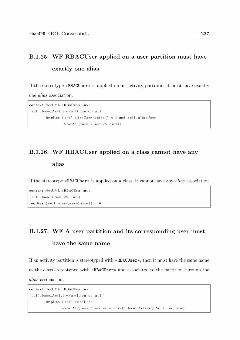
rbacUML OCL Constraints 227
B.1.25. WF RBACUser applied on a user partition must have
exactly one alias
If the stereotype «RBACUser» is applied on an activity partition, it must have exactly
one alias association.
context rbacUML : : RBACUser inv :
( s e l f . b a s e Ac t i v i t yPa r t i t i o n <> nu l l )
implies ( s e l f . a l i a sUse r−>s i z e ( ) = 1 and s e l f . a l i a sU s e r
−>f o rA l l ( base C la s s <> nu l l ) )
B.1.26. WF RBACUser applied on a class cannot have any
alias
If the stereotype «RBACUser» is applied on a class, it cannot have any alias association.
context rbacUML : : RBACUser inv :
( s e l f . ba se C la s s <> nu l l )
implies ( s e l f . a l i a sUse r−>s i z e ( ) = 0)
B.1.27. WF A user partition and its corresponding user must
have the same name
If an activity partition is stereotyped with «RBACUser», then it must have the same name
as the class stereotyped with «RBACUser» and associated to the partition through the
alias association.
context rbacUML : : RBACUser inv :
( s e l f . b a s e Ac t i v i t yPa r t i t i o n <> nu l l )
implies ( s e l f . a l i a sU s e r
−>f o rA l l ( base C la s s . name = s e l f . b a s e Ac t i v i t yPa r t i t i o n . name) )

228 rbacUML OCL Constraints
B.1.28. WF Roles activated on a user partition cannot break a
DSoD constraint
The roles activated on a user partition cannot break any DSoD constraint. Therefore, if
two roles participate in a DSoD constraint, they cannot be both activated on the same
user partition.
context rbacUML : : RBACUser inv :
s e l f . rBACRole−>f o rA l l ( ro l e1 , r o l e 2 | r o l e 1 . dsod1−>exc ludes ( r o l e 2 ) )
B.1.29. WF Roles activated on a user partition must be
assigned to the corresponding user
In an activity partition stereotyped with «RBACUser», all the associations to roles must
be of roles that have been assigned to the partition’s corresponding user.
context rbacUML : : RBACUser inv :
( s e l f . b a s e Ac t i v i t yPa r t i t i o n <> nu l l )
implies ( s e l f . a l i a sU s e r . rBACRole
−>union ( s e l f . a l i a sU s e r . rBACRole . base Class−>asSet ( ) . a l lPa r en t s ( ) .
oclAsType ( Class ) . extension RBACRole )−>asSet ( )
−>i n c l ud e sA l l ( s e l f . rBACRole . base C la s s . extension RBACRole ) )
B.1.30. WF A message referring to Restricted operations must
be Restricted
All messages referring to operations stereotyped with «Restricted» must themselves be
stereotyped with «Restricted».

rbacUML OCL Constraints 229
context rbacUML : : Re s t r i c t ed inv :
( s e l f . base Operat ion <> nu l l ) implies ( s e l f . al lOwningPackages ( )−>s e l e c t ( pkg | pkg .
al lOwningPackages ( )−>isEmpty ( ) ) . allOwnedElements ( )−>s e l e c t ( e l t | e l t . oc l IsTypeOf (
Message ) ) . oclAsType (Message )
−>s e l e c t (msg | msg . getAppl i edStereotype ( ’rbacUML : : Re s t r i c t ed ’ ) = nu l l ) .
oclAsType (Message ) . s i gna tu r e . oclAsType ( Operation )
−>s e l e c t ( op | op = s e l f )−>s i z e ( ) = 0)
B.1.31. WF A Restricted operation must be assigned at least
one permission
An operation stereotyped with «Restricted» must have at least one association to a
permission.
context rbacUML : : Re s t r i c t ed inv :
( s e l f . base Operat ion <> nu l l ) implies ( s e l f . permiss ion−>s i z e ( ) > 0)
B.1.32. WF A Restricted message must refer to a Restricted
operation
Messages stereotyped with «Restricted» must refer to operations stereotyped with
«Restricted».
context rbacUML : : Re s t r i c t ed inv :
( s e l f . base Message <> nu l l )
implies
( s e l f . base Message . s i gna tu r e . ge tAppl i edStereotype ( ’rbacUML : : Re s t r i c t ed ’ ) <> nu l l )
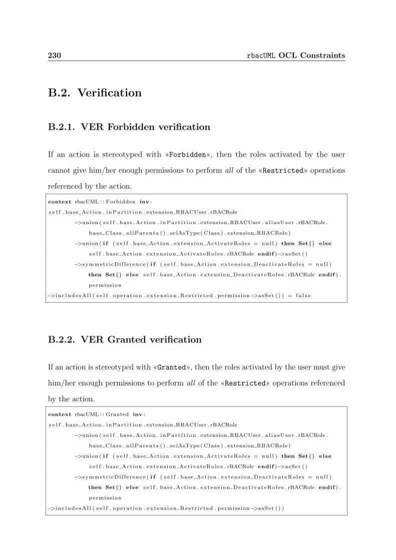
230 rbacUML OCL Constraints
B.2. Verification
B.2.1. VER Forbidden verification
If an action is stereotyped with «Forbidden», then the roles activated by the user
cannot give him/her enough permissions to perform all of the «Restricted» operations
referenced by the action.
context rbacUML : : Forbidden inv :
s e l f . base Act ion . i nPa r t i t i o n . extension RBACUser . rBACRole
−>union ( s e l f . base Act ion . i nPa r t i t i o n . extension RBACUser . a l i a sU s e r . rBACRole .
base C la s s . a l lPa r en t s ( ) . oclAsType ( Class ) . extension RBACRole )
−>union ( i f ( s e l f . base Act ion . ex t en s i on Act i va t eRo l e s = nu l l ) then Set{} else
s e l f . base Act ion . ex t en s i on Act i va t eRo l e s . rBACRole endif )−>asSet ( )
−>symmetr i cDi f f e rence ( i f ( s e l f . base Act ion . ex t en s i on Deac t i va t eRo l e s = nu l l )
then Set{} else s e l f . base Act ion . ex t en s i on Deac t i va t eRo l e s . rBACRole endif ) .
permis s ion
−>i n c l ud e sA l l ( s e l f . ope ra t i on . e x t en s i on Re s t r i c t ed . permiss ion−>asSet ( ) ) = f a l s e
B.2.2. VER Granted verification
If an action is stereotyped with «Granted», then the roles activated by the user must give
him/her enough permissions to perform all of the «Restricted» operations referenced
by the action.
context rbacUML : : Granted inv :
s e l f . base Act ion . i nPa r t i t i o n . extension RBACUser . rBACRole
−>union ( s e l f . base Act ion . i nPa r t i t i o n . extension RBACUser . a l i a sU s e r . rBACRole .
base C la s s . a l lPa r en t s ( ) . oclAsType ( Class ) . extension RBACRole )
−>union ( i f ( s e l f . base Act ion . ex t en s i on Act i va t eRo l e s = nu l l ) then Set{} else
s e l f . base Act ion . ex t en s i on Act i va t eRo l e s . rBACRole endif )−>asSet ( )
−>symmetr i cDi f f e rence ( i f ( s e l f . base Act ion . ex t en s i on Deac t i va t eRo l e s = nu l l )
then Set{} else s e l f . base Act ion . ex t en s i on Deac t i va t eRo l e s . rBACRole endif ) .
permis s ion
−>i n c l ud e sA l l ( s e l f . ope ra t i on . e x t en s i on Re s t r i c t ed . permiss ion−>asSet ( ) )

rbacUML OCL Constraints 231
B.3. Satisfiability
B.3.1. SAT A Granted action should be executable by at least
one user
Detects actions stereotyped with «Granted» that no user, with all their roles activated,
can perform.
context rbacUML : : Granted inv :
s e l f . getNearestPackage ( ) . allOwnedElements ( )
−>s e l e c t ( usr | usr . oc l IsTypeOf ( Class ) and usr . ge tAppl i edStereotype ( ’rbacUML : :
RBACUser ’ ) <> nu l l ) . oclAsType ( Class )
−>e x i s t s ( usr | usr . oclAsType ( Class ) . extension RBACUser . rBACRole . permiss ion−>
asSet ( )
−>union ( usr . oclAsType ( Class ) . extension RBACUser
. rBACRole . base C la s s . a l lPa r en t s ( ) . oclAsType
( Class ) . extension RBACRole . permiss ion−>
asSet ( ) )
−>i n c l ud e sA l l ( s e l f . ope ra t i on . e x t en s i on Re s t r i c t ed . permiss ion−>asSet ( ) ) )
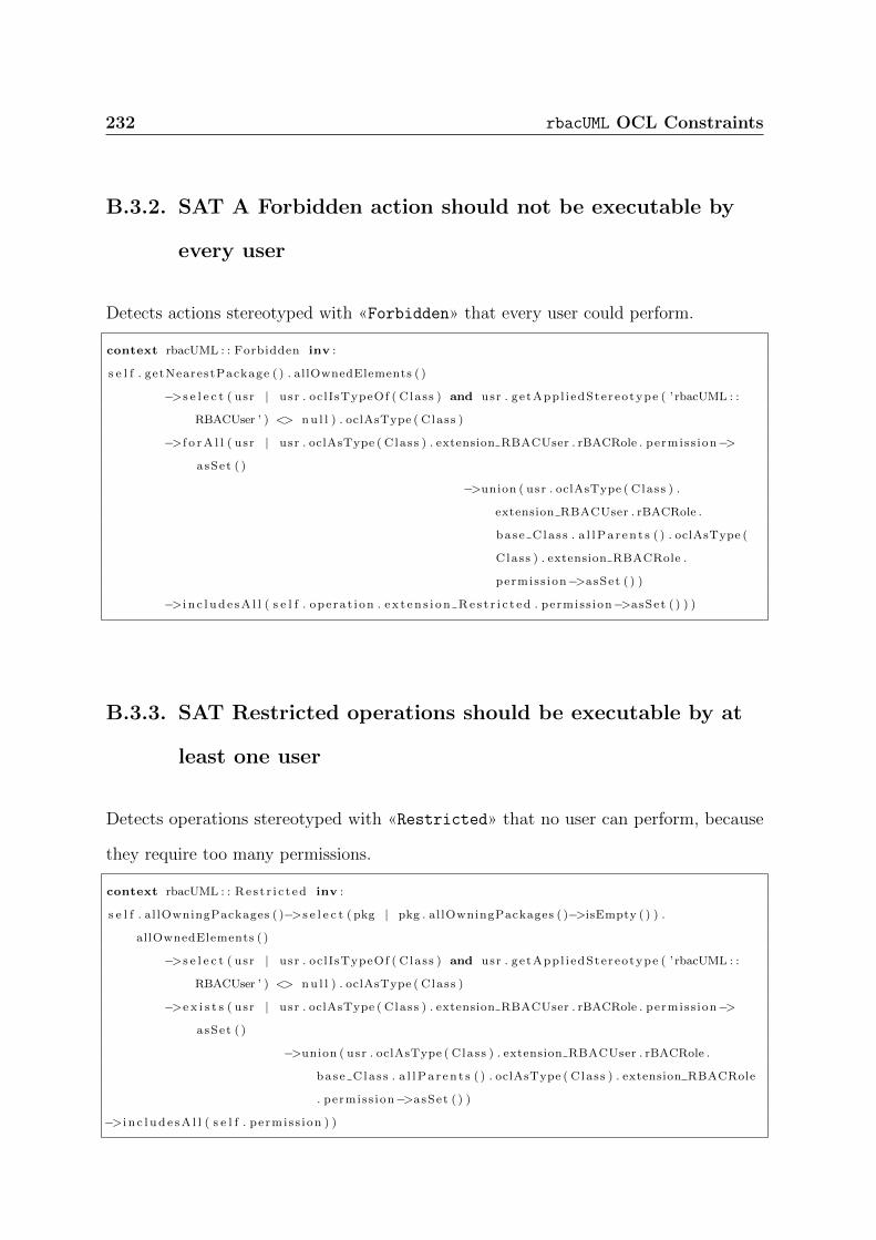
232 rbacUML OCL Constraints
B.3.2. SAT A Forbidden action should not be executable by
every user
Detects actions stereotyped with «Forbidden» that every user could perform.
context rbacUML : : Forbidden inv :
s e l f . getNearestPackage ( ) . allOwnedElements ( )
−>s e l e c t ( usr | usr . oc l IsTypeOf ( Class ) and usr . ge tAppl i edStereotype ( ’rbacUML : :
RBACUser ’ ) <> nu l l ) . oclAsType ( Class )
−>f o rA l l ( usr | usr . oclAsType ( Class ) . extension RBACUser . rBACRole . permiss ion−>
asSet ( )
−>union ( usr . oclAsType ( Class ) .
extension RBACUser . rBACRole .
base C la s s . a l lPa r en t s ( ) . oclAsType (
Class ) . extension RBACRole .
permiss ion−>asSet ( ) )
−>i n c l ud e sA l l ( s e l f . ope ra t i on . e x t en s i on Re s t r i c t ed . permiss ion−>asSet ( ) ) )
B.3.3. SAT Restricted operations should be executable by at
least one user
Detects operations stereotyped with «Restricted» that no user can perform, because
they require too many permissions.
context rbacUML : : Re s t r i c t ed inv :
s e l f . al lOwningPackages ( )−>s e l e c t ( pkg | pkg . al lOwningPackages ( )−>isEmpty ( ) ) .
allOwnedElements ( )
−>s e l e c t ( usr | usr . oc l IsTypeOf ( Class ) and usr . ge tAppl i edStereotype ( ’rbacUML : :
RBACUser ’ ) <> nu l l ) . oclAsType ( Class )
−>e x i s t s ( usr | usr . oclAsType ( Class ) . extension RBACUser . rBACRole . permiss ion−>
asSet ( )
−>union ( usr . oclAsType ( Class ) . extension RBACUser . rBACRole .
base C la s s . a l lPa r en t s ( ) . oclAsType ( Class ) . extension RBACRole
. permiss ion−>asSet ( ) )
−>i n c l ud e sA l l ( s e l f . pe rmis s ion ) )
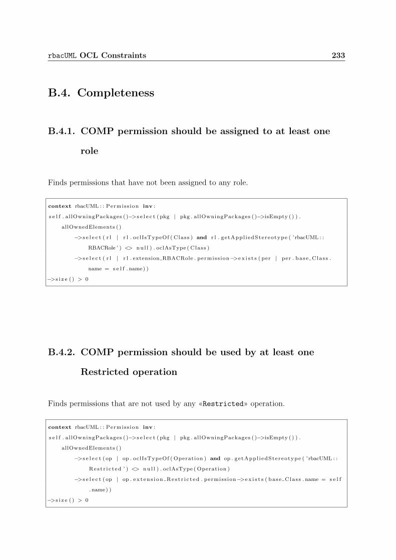
rbacUML OCL Constraints 233
B.4. Completeness
B.4.1. COMP permission should be assigned to at least one
role
Finds permissions that have not been assigned to any role.
context rbacUML : : Permiss ion inv :
s e l f . al lOwningPackages ( )−>s e l e c t ( pkg | pkg . al lOwningPackages ( )−>isEmpty ( ) ) .
allOwnedElements ( )
−>s e l e c t ( r l | r l . oc l IsTypeOf ( Class ) and r l . ge tAppl i edStereotype ( ’rbacUML : :
RBACRole ’ ) <> nu l l ) . oclAsType ( Class )
−>s e l e c t ( r l | r l . extension RBACRole . permiss ion−>e x i s t s ( per | per . base C la s s .
name = s e l f . name) )
−>s i z e ( ) > 0
B.4.2. COMP permission should be used by at least one
Restricted operation
Finds permissions that are not used by any «Restricted» operation.
context rbacUML : : Permiss ion inv :
s e l f . al lOwningPackages ( )−>s e l e c t ( pkg | pkg . al lOwningPackages ( )−>isEmpty ( ) ) .
allOwnedElements ( )
−>s e l e c t ( op | op . oclIsTypeOf ( Operation ) and op . getAppl i edStereotype ( ’rbacUML : :
Re s t r i c t ed ’ ) <> nu l l ) . oclAsType ( Operation )
−>s e l e c t ( op | op . e x t en s i on Re s t r i c t ed . permiss ion−>e x i s t s ( base C la s s . name = s e l f
. name) )
−>s i z e ( ) > 0

234 rbacUML OCL Constraints
B.4.3. COMP A role should be assigned at least one direct
permission
Finds roles that have not been assigned any permissions.
context rbacUML : : RBACRole inv :
s e l f . permiss ion−>s i z e ( ) > 0
B.4.4. COMP A role should be assigned to at least one user
Finds roles that have not been assigned to any user.
context rbacUML : : RBACRole inv :
s e l f . al lOwningPackages ( )−>s e l e c t ( pkg | pkg . al lOwningPackages ( )−>isEmpty ( ) ) .
allOwnedElements ( )
−>s e l e c t ( usr | usr . oc l IsTypeOf ( Class ) and usr . ge tAppl i edStereotype ( ’rbacUML : :
RBACUser ’ ) <> nu l l ) . oclAsType ( Class )
−>s e l e c t ( usr | usr . extension RBACUser . rBACRole−>e x i s t s ( r l | r l . ba se C la s s . name
= s e l f . name) )
−>s i z e ( ) > 0
B.4.5. COMP A user should be assigned at least one role
Finds users that have not been assigned any role.
context rbacUML : : RBACUser inv :
( s e l f . ba se C la s s <> nu l l ) implies ( s e l f . rBACRole−>s i z e ( ) > 0)

rbacUML OCL Constraints 235
B.5. Coverage
B.5.1. COV Restricted operations should be used by at least
one action
Finds «Restricted» operations that are not used in any action.
context rbacUML : : Re s t r i c t ed inv :
s e l f . base Operat ion <> nu l l implies
s e l f . al lOwningPackages ( )−>s e l e c t ( pkg | pkg . al lOwningPackages ( )−>isEmpty ( ) ) .
allOwnedElements ( )
−>s e l e c t ( act | act . oc l I sKindOf ( Action ) and act . ge tAppl i edStereotype ( ’rbacUML : :
Granted ’ ) <> nu l l ) . oclAsType ( Action )
−>s e l e c t ( act | act . extens ion Granted . operat ion−>e x i s t s (name = s e l f . name) )
−>union (
s e l f . al lOwningPackages ( )−>s e l e c t ( pkg | pkg . al lOwningPackages ( )−>isEmpty ( ) ) .
allOwnedElements ( )
−>s e l e c t ( act | act . oc l I sKindOf ( Action ) and act . ge tAppl i edStereotype ( ’rbacUML : :
Forbidden ’ ) <> nu l l ) . oclAsType ( Action )
−>s e l e c t ( act | act . extens ion Forb idden . operat ion−>e x i s t s (name = s e l f . name) )
)−>s i z e ( ) > 0
B.5.2. COV A user should be represented on at least one user
partition
Finds users that are not referenced in any activity partition.
context rbacUML : : RBACUser inv :
s e l f . ba se C la s s <> nu l l implies
s e l f . al lOwningPackages ( )−>s e l e c t ( pkg | pkg . al lOwningPackages ( )−>isEmpty ( ) ) .
allOwnedElements ( )
−>s e l e c t ( act | act . oc l I sKindOf ( Ac t i v i t yPa r t i t i o n ) and act . ge tAppl i edStereotype (
’rbacUML : : RBACUser ’ ) <> nu l l ) . oclAsType ( Ac t i v i t yPa r t i t i o n )
−>s e l e c t ( act | ( act . name = s e l f . name) and ( act . extension RBACUser . a l i a sU s e r .
base C la s s = s e l f ) )
−>s i z e ( ) > 0
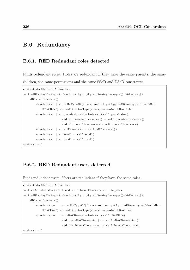
236 rbacUML OCL Constraints
B.6. Redundancy
B.6.1. RED Redundant roles detected
Finds redundant roles. Roles are redundant if they have the same parents, the same
children, the same permissions and the same SSoD and DSoD constraints.
context rbacUML : : RBACRole inv :
s e l f . al lOwningPackages ( )−>s e l e c t ( pkg | pkg . al lOwningPackages ( )−>isEmpty ( ) ) .
allOwnedElements ( )
−>s e l e c t ( r l | r l . oc l IsTypeOf ( Class ) and r l . ge tAppl i edStereotype ( ’rbacUML : :
RBACRole ’ ) <> nu l l ) . oclAsType ( Class ) . extension RBACRole
−>s e l e c t ( r l | r l . permiss ion−>i n c l ud e sA l l ( s e l f . pe rmis s ion )
and r l . permiss ion−>s i z e ( ) = s e l f . permiss ion−>s i z e ( )
and r l . ba se C la s s . name <> s e l f . ba se C la s s . name)
−>s e l e c t ( r l | r l . a l lPa r en t s ( ) = s e l f . a l lPa r en t s ( ) )
−>s e l e c t ( r l | r l . ssod1 = s e l f . ssod1 )
−>s e l e c t ( r l | r l . dsod1 = s e l f . dsod1 )
−>s i z e ( ) = 0
B.6.2. RED Redundant users detected
Finds redundant users. Users are redundant if they have the same roles.
context rbacUML : : RBACUser inv :
s e l f . rBACRole−>s i z e ( ) > 0 and s e l f . ba se C la s s <> nu l l implies
s e l f . al lOwningPackages ( )−>s e l e c t ( pkg | pkg . al lOwningPackages ( )−>isEmpty ( ) ) .
allOwnedElements ( )
−>s e l e c t ( usr | usr . oc l IsTypeOf ( Class ) and usr . ge tAppl i edStereotype ( ’rbacUML : :
RBACUser ’ ) <> nu l l ) . oclAsType ( Class ) . extension RBACUser
−>s e l e c t ( usr | usr . rBACRole−>i n c l ud e sA l l ( s e l f . rBACRole )
and usr . rBACRole−>s i z e ( ) = s e l f . rBACRole−>s i z e ( )
and usr . base C la s s . name <> s e l f . ba se C la s s . name)
−>s i z e ( ) = 0

Appendix C.
OCL Evaluation Performance Study
Details
237

238 OCL Evaluation Performance Study Details
C.1. Performance Evaluation Details
This section provides detailed tables for our performance analysis in Section 5.4. For each
model size, 5 different models have been generated. The results were then aggregated by
taking, for each model size, the average evaluation time. Here, we provide the data used
for Figs 5.1 and 5.2.
Table C.1 details the evaluation time of verified models, Table C.2 details the evaluation
time of malformed models, i.e. those that have failed the evaluation of well-formedness
queries, and Table C.3 details the evaluation time of unverified models, i.e. models that
have passed the well-formedness queries, but failed the verification queries. In those
three tables, size is the size of the model (number of elements + number of associations),
Full is the evaluation time of all the rbacUML queries in one pass, WF is the evaluation
time of well-formedness queries only, VER is the evaluation time of verification queries
only, SAT is the evaluation time of satisfiability constraints only, COV is the evaluation
time of coverage queries only, COMP is the evaluation time of completeness constraints
only, RED is the evaluation time of redundancy constraints only, SUM is the sum of the
evaluation times of WF, VER,SAT, COV, COMP and RED, and finally, LAZY is the
evaluation time of all the rbacUML queries using the lazy evaluation strategy.
Table C.1.: Evaluation times (in seconds) for verified models
Size Full WF VER SAT COV COMP RED SUM LAZY
221 27.992 11.525 2.977 4.126 2.474 3.851 3.315 28.270 23.975
433 26.547 10.867 2.639 3.844 2.451 3.892 3.300 26.994 22.973
645 18.637 7.271 1.900 2.953 1.818 2.916 2.404 19.265 16.123
837 19.857 7.491 1.632 3.012 2.037 3.518 2.745 20.438 17.163
1033 21.290 7.800 1.196 3.026 2.320 4.295 3.187 21.826 18.572
2057 30.110 7.752 1.224 5.728 3.240 8.122 4.762 30.830 24.767
3074 44.378 7.622 1.231 10.194 4.728 14.511 7.357 45.644 34.873
4116 69.415 9.637 1.531 16.949 7.296 24.126 11.556 71.097 53.432
6168 134.108 12.627 1.922 35.267 13.900 50.458 22.644 136.819 100.211
8211 214.269 10.557 1.552 59.711 21.645 85.316 36.249 215.033 154.812
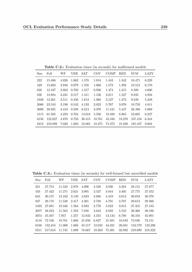
OCL Evaluation Performance Study Details 239
Table C.2.: Evaluation times (in seconds) for malformed models
Size Full WF VER SAT COV COMP RED SUM LAZY
222 15.486 4.026 1.062 1.578 1.018 1.443 1.342 10.471 6.229
429 15.603 3.948 0.979 1.558 1.060 1.573 1.392 10.512 6.170
638 12.437 2.862 0.702 1.317 0.936 1.474 1.215 8.508 4.600
836 13.884 3.231 0.517 1.411 1.136 2.011 1.527 9.835 4.934
1039 12.261 2.511 0.456 1.613 1.068 2.127 1.472 9.249 5.249
2066 23.543 3.190 0.542 4.133 2.023 5.767 3.076 18.733 4.811
3090 38.925 3.419 0.588 8.213 3.376 11.441 5.447 32.486 5.069
4115 61.505 4.233 0.704 14.018 5.356 19.488 8.865 52.665 6.237
6156 122.027 4.878 0.750 30.415 10.761 42.340 18.270 107.416 6.344
8212 210.898 7.030 1.003 52.865 18.275 74.372 31.620 185.167 9.604
Table C.3.: Evaluation times (in seconds) for well-formed but unverified models
Size Full WF VER SAT COV COMP RED SUM LAZY
221 27.754 11.532 2.978 4.096 2.428 3.830 3.284 28.151 27.877
433 27.422 11.271 2.621 3.905 2.527 4.044 3.405 27.775 27.552
645 30.157 12.162 3.149 4.623 2.686 4.419 3.612 30.653 30.370
837 29.178 11.526 2.417 4.301 2.788 4.791 3.787 29.612 29.366
1033 27.081 10.340 1.564 3.934 2.776 5.023 3.815 27.455 27.183
2057 38.823 11.505 1.763 7.838 3.842 8.859 5.552 39.360 39.190
3074 45.507 7.957 1.257 12.832 4.355 13.134 6.780 46.316 45.901
4116 72.536 10.761 1.666 21.856 6.827 21.881 10.843 73.836 73.151
6168 132.454 11.000 1.666 45.517 12.042 44.321 20.031 134.579 133.296
8211 217.618 11.745 1.699 78.667 19.303 75.391 32.892 219.699 218.322

240 OCL Evaluation Performance Study Details
C.2. Generated Model
We reproduce in this section a small model generated by our model generator [4]. Below is
the configuration we passed to the code generator to create the model. Many parameters
can be set, and the model generator will aim to create a model with the specified number
of elements and associations.
<models>
<model name=”l i n0001”>
<wel l−formedness en fo rced=”true ” />
<v e r i f i c a t i o n en fo rced=”true ” />
<completeness en fo rced=”true ” />
<coverage en fo rced=”true ” />
<redundancy en fo rced=”true ” />
< s a t i s f i a b i l i t y en fo rced=”true ” />
<use r s num=”10”>
<r o l e s min=”5” max=”5”/>
</users>
<r o l e s num=”10”>
<ssod min=”0” max=”0” />
<dsod min=”0” max=”0” />
<h i e r a r c h i e s min=”0” max=”0” />
<permi s s i ons min=”5” max=”5” />
</ro l e s>
<permi s s i ons num=”10”>
</permiss ions>
<p a r t i t i o n s num=”3” />
<a c t i on s num=”10” granted=”5” forb idden=”5”>
<ope ra t i on s min=”5” max=”5” />
<r e s t r i c t e d−ope ra t i on s min=”5” max=”5” />
</act ions>
<ope ra t i on s num=”10” r e s t r i c t e d =”10”>
<permi s s i ons min=”5” max=”5” />
</operat ions>
<c l a s s e s num=”3” />
<a c t i v i t i e s num=”1” />
</model>
</models>

OCL Evaluation Performance Study Details 241
Table C.4.: List of inter-diagram associations for the randomly generated model
Origin End
restrictedOperation0 permissions 1, 2, 3, 8 and 10
restrictedOperation1 permissions 2, 3, 5, 6 and 8
restrictedOperation2 permissions 1, 2, 6, 7 and 9
restrictedOperation3 permissions 3, 4, 5, 6 and 8
restrictedOperation4 permissions 1, 3, 5, 6 and 8
restrictedOperation5 permissions 1, 2, 4, 7 and 8
restrictedOperation6 permissions 4, 7, 8, 9 and 10
restrictedOperation7 permissions 3, 4, 6, 7 and 9
restrictedOperation8 permissions 1, 2, 4, 6 and 7
restrictedOperation9 permissions 2, 3, 6, 7 and 10
User4 (partition) no roles
User5 (partition) roles 1, 2, 4, 6 and 7
User9 (partition) roles 4 and 9
GrantedAction1 «Restricted» operations 2, 4 and 6
GrantedAction4 «Restricted» operations 3 and 7
ForbiddenAction4 «Restricted» operations 7 and 9
The model is made of 10 users, 10 roles and 10 permissions. It actually is one of
the models we used for the performance evaluation in Section 5.4. Elements are named
according to their type and a counter. Fig. C.1 is the access control diagram, Fig. C.2 is
the class diagram, and Fig. C.3 is the activity diagram.
The associations between the diagram are not visible. We have grouped them in
Table C.4.
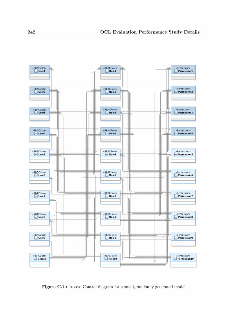
242 OCL Evaluation Performance Study Details
Figure C.1.: Access Control diagram for a small, randomly generated model

OCL Evaluation Performance Study Details 243
Figure C.2.: Class diagram for a small, randomly generated model
Figure C.3.: Activity diagram for a small, randomly generated model