Embed Size (px)
Citation preview

Open Core ProtocolSpecification
Release 2.1
OCP-IP Confidential

����������������� �����������
�������������������

© 2005 OCP-IP Association, All Rights Reserved.
Open Core Protocol Specification 2.1Document Revision 1.0
This document, including all software described in it, is furnished under the terms of the Open Core Protocol Specification License Agreement (the "License") and may only be used or copied in accordance with the terms of the License. The information in this document is a work in progress, jointly developed by the members of OCP-IP Association ("OCP-IP") and is furnished for informational use only.
The technology disclosed herein may be protected by one or more patents, copyrights, trademarks and/or trade secrets owned by or licensed to OCP-IP. OCP-IP reserves all rights with respect to such technology and related materials. Any use of the protected technology and related material beyond the terms of the License without the prior written consent of OCP-IP is prohibited.
This document contains material that is confidential to OCP-IP and its members and licensors. The user should assume that all materials contained and/or referenced in this document are confidential and proprietary unless otherwise indicated or apparent from the nature of such materials (for example, references to publicly available forms or documents). Disclosure or use of this document or any material contained herein, other than as expressly permitted, is prohibited without the prior written consent of OCP-IP or such other party that may grant permission to use its proprietary material.
The trademarks, logos, and service marks displayed in this document are the registered and unregistered trademarks of OCP-IP, its members and its licensors. The following trademarks of Sonics, Inc. have been licensed to OCP-IP: FastForward, SonicsIA, CoreCreator, SiliconBackplane, SiliconBackplane Agent, InitiatorAgent Module, TargetAgent Module, ServiceAgent Module, SOCCreator, and Open Core Protocol.
The copyright and trademarks owned by OCP-IP, whether registered or unregistered, may not be used in connection with any product or service that is not owned, approved or distributed by OCP-IP, and may not be used in any manner that is likely to cause customer confusion or that disparages OCP-IP. Nothing contained in this document should be construed as granting by implication, estoppel, or otherwise, any license or right to use any copyright without the express written consent of OCP-IP, its licensors or a third party owner of any such trademark.
Printed in the United States of America.
Part number: 161-000125-0003
EXCEPT AS OTHERWISE EXPRESSLY PROVIDED, THE OPEN CORE PROTOCOL (OCP) SPECIFICATION IS PROVIDED BY OCP-IP TO MEMBERS "AS IS" WITHOUT WARRANTY OF ANY KIND, EXPRESS, IMPLIED OR STATUTORY, INCLUDING BUT NOT LIMITED TO ANY IMPLIED WARRANTIES OF MERCHANTABILITY, FITNESS FOR A PARTICULAR PURPOSE AND NONINFRINGEMENT OF THIRD PARTY RIGHTS.
OCP-IP SHALL NOT BE LIABLE FOR ANY DIRECT, INDIRECT, INCIDENTAL, SPECIAL OR CONSEQUENTIAL DAMAGES OF ANY KIND OR NATURE WHATSOEVER (INCLUDING, WITHOUT LIMITATION, ANY DAMAGES ARISING FROM LOSS OF USE OR LOST BUSINESS, REVENUE, PROFITS, DATA OR GOODWILL) ARISING IN CONNECTION WITH ANY INFRINGEMENT CLAIMS BY THIRD PARTIES OR THE SPECIFICATION, WHETHER IN AN ACTION IN CONTRACT, TORT, STRICT LIABILITY, NEGLIGENCE, OR ANY OTHER THEORY, EVEN IF ADVISED OF THE POSSIBILITY OF SUCH DAMAGES.

Contents
1 Overview 1
OCP Characteristics . . . . . . . . . . . . . . . . . . . . . . . . . . . . 2
Compliance . . . . . . . . . . . . . . . . . . . . . . . . . . . . . . . . 3
Part I Specification 5
2 Theory of Operation 7
3 Signals and Encoding 13
Dataflow Signals . . . . . . . . . . . . . . . . . . . . . . . . . . . . . 14
Basic Signals . . . . . . . . . . . . . . . . . . . . . . . . . . . . . . 14
Simple Extensions. . . . . . . . . . . . . . . . . . . . . . . . . . . . 16
Burst Extensions . . . . . . . . . . . . . . . . . . . . . . . . . . . . 19
Tag Extensions . . . . . . . . . . . . . . . . . . . . . . . . . . . . . 21
Thread Extensions . . . . . . . . . . . . . . . . . . . . . . . . . . . 22
Sideband Signals . . . . . . . . . . . . . . . . . . . . . . . . . . . . . 24
Reset, Interrupt, Error, and Core-Specific Flag Signals . . . . . . . . . 24
Control and Status Signals . . . . . . . . . . . . . . . . . . . . . . . 25
Test Signals . . . . . . . . . . . . . . . . . . . . . . . . . . . . . . . . 26
Scan Interface . . . . . . . . . . . . . . . . . . . . . . . . . . . . . . 27
Clock Control Interface . . . . . . . . . . . . . . . . . . . . . . . . . 27
Debug and Test Interface . . . . . . . . . . . . . . . . . . . . . . . . 27
Signal Configuration . . . . . . . . . . . . . . . . . . . . . . . . . . . 28
Signal Directions . . . . . . . . . . . . . . . . . . . . . . . . . . . . 31
4 Protocol Semantics 33
Signal Groups . . . . . . . . . . . . . . . . . . . . . . . . . . . . . . . 34
Combinational Dependencies . . . . . . . . . . . . . . . . . . . . . . . 35
Signal Timing and Protocol Phases . . . . . . . . . . . . . . . . . . . . 36
Dataflow Signals. . . . . . . . . . . . . . . . . . . . . . . . . . . . . 36
Sideband and Test Signals . . . . . . . . . . . . . . . . . . . . . . . 40
Transfer Effects . . . . . . . . . . . . . . . . . . . . . . . . . . . . . . 41
Partial Word Transfers. . . . . . . . . . . . . . . . . . . . . . . . . . 43
Posting Semantics . . . . . . . . . . . . . . . . . . . . . . . . . . . . 43
Endianness . . . . . . . . . . . . . . . . . . . . . . . . . . . . . . . . 43
viii Open Core Protocol Specification
Burst Definition . . . . . . . . . . . . . . . . . . . . . . . . . . . . . . 44
Burst Address Sequence. . . . . . . . . . . . . . . . . . . . . . . . . 45
Burst Length, Precise and Imprecise Bursts . . . . . . . . . . . . . . . 46
Constant Fields in Bursts . . . . . . . . . . . . . . . . . . . . . . . . 47
Atomicity . . . . . . . . . . . . . . . . . . . . . . . . . . . . . . . . 47
Single Request / Multiple Data Bursts (Packets) . . . . . . . . . . . . . 47
MReqLast, MDataLast, SRespLast . . . . . . . . . . . . . . . . . . . . 47
Tags . . . . . . . . . . . . . . . . . . . . . . . . . . . . . . . . . . . 48
Ordering Restrictions . . . . . . . . . . . . . . . . . . . . . . . . . . 48
Threads and Connections . . . . . . . . . . . . . . . . . . . . . . . . . 49
OCP Configuration . . . . . . . . . . . . . . . . . . . . . . . . . . . . 50
Protocol Options. . . . . . . . . . . . . . . . . . . . . . . . . . . . . 50
Phase Options . . . . . . . . . . . . . . . . . . . . . . . . . . . . . . 54
Signal Options. . . . . . . . . . . . . . . . . . . . . . . . . . . . . . 55
Minimum Implementation . . . . . . . . . . . . . . . . . . . . . . . . 55
OCP Interface Interoperability . . . . . . . . . . . . . . . . . . . . . . 55
Configuration Parameter Defaults . . . . . . . . . . . . . . . . . . . . 58
5 Interface Configuration File 63
Lexical Grammar . . . . . . . . . . . . . . . . . . . . . . . . . . . . . 63
Syntax . . . . . . . . . . . . . . . . . . . . . . . . . . . . . . . . . . 64
6 Core RTL Configuration File 69
Syntax . . . . . . . . . . . . . . . . . . . . . . . . . . . . . . . . . . 69
Components . . . . . . . . . . . . . . . . . . . . . . . . . . . . . . . 70
Sample RTL Configuration File . . . . . . . . . . . . . . . . . . . . . . 78
7 Core Timing 81
Timing Parameters . . . . . . . . . . . . . . . . . . . . . . . . . . . . 82
Minimum Parameters . . . . . . . . . . . . . . . . . . . . . . . . . . 82
Hold-time Parameters . . . . . . . . . . . . . . . . . . . . . . . . . . 82
Technology Variables . . . . . . . . . . . . . . . . . . . . . . . . . . 83
Connecting Two OCP Cores . . . . . . . . . . . . . . . . . . . . . . . 84
Core Synthesis Configuration File . . . . . . . . . . . . . . . . . . . . . 86
Syntax Conventions . . . . . . . . . . . . . . . . . . . . . . . . . . . 86
Version Section . . . . . . . . . . . . . . . . . . . . . . . . . . . . . 88
Clock Section . . . . . . . . . . . . . . . . . . . . . . . . . . . . . . 88
Area Section . . . . . . . . . . . . . . . . . . . . . . . . . . . . . . . 88
Contents ix
Port Constraints Section. . . . . . . . . . . . . . . . . . . . . . . . . 89
Max Delay Constraints . . . . . . . . . . . . . . . . . . . . . . . . . 94
False Path Constraints . . . . . . . . . . . . . . . . . . . . . . . . . 94
Sample Core Synthesis Configuration File . . . . . . . . . . . . . . . . 95
Part II Guidelines 97
8 Timing Diagrams 99
Simple Write and Read Transfer . . . . . . . . . . . . . . . . . . . . . 100
Request Handshake . . . . . . . . . . . . . . . . . . . . . . . . . . . 101
Request Handshake and Separate Response . . . . . . . . . . . . . . 102
Write with Response . . . . . . . . . . . . . . . . . . . . . . . . . . 103
Non-Posted Write . . . . . . . . . . . . . . . . . . . . . . . . . . . . 105
Burst Write . . . . . . . . . . . . . . . . . . . . . . . . . . . . . . . 106
Non-Pipelined Read . . . . . . . . . . . . . . . . . . . . . . . . . . . 107
Pipelined Request and Response . . . . . . . . . . . . . . . . . . . . 109
Response Accept . . . . . . . . . . . . . . . . . . . . . . . . . . . . 110
Incrementing Precise Burst Read . . . . . . . . . . . . . . . . . . . . 112
Incrementing Imprecise Burst Read . . . . . . . . . . . . . . . . . . . 114
Wrapping Burst Read . . . . . . . . . . . . . . . . . . . . . . . . . . 116
Incrementing Burst Read with IDLE Request Cycle . . . . . . . . . . . 118
Incrementing Burst Read with NULL Response Cycle . . . . . . . . . . 120
Single Request Burst Read . . . . . . . . . . . . . . . . . . . . . . . 122
Datahandshake Extension . . . . . . . . . . . . . . . . . . . . . . . 123
Burst Write with Combined Request and Data . . . . . . . . . . . . . 125
Tagged Reads . . . . . . . . . . . . . . . . . . . . . . . . . . . . . . 127
Tagged Bursts . . . . . . . . . . . . . . . . . . . . . . . . . . . . . . 129
Threaded Read . . . . . . . . . . . . . . . . . . . . . . . . . . . . . 131
Threaded Read with Thread Busy . . . . . . . . . . . . . . . . . . . . 133
Threaded Read with Thread Busy Exact . . . . . . . . . . . . . . . . . 135
Reset . . . . . . . . . . . . . . . . . . . . . . . . . . . . . . . . . . 136
9 Developers Guidelines 137
Basic OCP . . . . . . . . . . . . . . . . . . . . . . . . . . . . . . . 137
Signal Timing . . . . . . . . . . . . . . . . . . . . . . . . . . . . . 138
State Machine Examples . . . . . . . . . . . . . . . . . . . . . . . 140
OCP Subsets . . . . . . . . . . . . . . . . . . . . . . . . . . . . . 145
Simple OCP Extensions . . . . . . . . . . . . . . . . . . . . . . . . . 146
x Open Core Protocol Specification
Byte Enables . . . . . . . . . . . . . . . . . . . . . . . . . . . . . 146
Multiple Address Spaces. . . . . . . . . . . . . . . . . . . . . . . . 147
In-Band Information. . . . . . . . . . . . . . . . . . . . . . . . . . 148
Burst Extensions . . . . . . . . . . . . . . . . . . . . . . . . . . . . 149
OCP-IP 2.0 Burst Capabilities . . . . . . . . . . . . . . . . . . . . . 149
Compatibility with the OCP 1.0 Burst Model. . . . . . . . . . . . . . 152
Tags . . . . . . . . . . . . . . . . . . . . . . . . . . . . . . . . . . 154
Threads and Connections . . . . . . . . . . . . . . . . . . . . . . . . 155
Threads . . . . . . . . . . . . . . . . . . . . . . . . . . . . . . . . 155
Connections . . . . . . . . . . . . . . . . . . . . . . . . . . . . . . 160
OCP Specific Features . . . . . . . . . . . . . . . . . . . . . . . . . . 161
Write Semantics . . . . . . . . . . . . . . . . . . . . . . . . . . . . 161
Lazy Synchronization . . . . . . . . . . . . . . . . . . . . . . . . . 163
OCP and Endianness . . . . . . . . . . . . . . . . . . . . . . . . . 165
Sideband Signals . . . . . . . . . . . . . . . . . . . . . . . . . . . . 167
Reset Handling . . . . . . . . . . . . . . . . . . . . . . . . . . . . 167
Debug and Test Interface . . . . . . . . . . . . . . . . . . . . . . . . 169
Scan Control . . . . . . . . . . . . . . . . . . . . . . . . . . . . . 169
Clock Control . . . . . . . . . . . . . . . . . . . . . . . . . . . . . 169
10 Timing Guidelines 171
Level0 Timing . . . . . . . . . . . . . . . . . . . . . . . . . . . . . . 172
Level1 Timing . . . . . . . . . . . . . . . . . . . . . . . . . . . . . . 172
Level2 Timing . . . . . . . . . . . . . . . . . . . . . . . . . . . . . . 172
11 OCP Profiles 175
Profile Types . . . . . . . . . . . . . . . . . . . . . . . . . . . . . . 177
Native OCP Profiles . . . . . . . . . . . . . . . . . . . . . . . . . . . 178
Block Data Flow Profile . . . . . . . . . . . . . . . . . . . . . . . . 178
Sequential Undefined Length Data Flow Profile . . . . . . . . . . . . 181
Register Access Profile . . . . . . . . . . . . . . . . . . . . . . . . . 183
Bridging Profiles . . . . . . . . . . . . . . . . . . . . . . . . . . . . 185
Simple H-bus Profile. . . . . . . . . . . . . . . . . . . . . . . . . . 185
X-Bus Packet Write Profile. . . . . . . . . . . . . . . . . . . . . . . 187
X-Bus Packet Read Profile . . . . . . . . . . . . . . . . . . . . . . . 189
12 Verification Guidelines 193
Signal Testing . . . . . . . . . . . . . . . . . . . . . . . . . . . . . . 194
Contents xi
Signal Retraction Testing . . . . . . . . . . . . . . . . . . . . . . . 195
Phase-Based Checks . . . . . . . . . . . . . . . . . . . . . . . . . . 196
Request Phase Checks. . . . . . . . . . . . . . . . . . . . . . . . . 196
Datahandshake Phase. . . . . . . . . . . . . . . . . . . . . . . . . 197
Response Phase . . . . . . . . . . . . . . . . . . . . . . . . . . . . 197
Transfer-Based Checks . . . . . . . . . . . . . . . . . . . . . . . . . 197
Transaction-Based Checks . . . . . . . . . . . . . . . . . . . . . . . 198
Burst Checks . . . . . . . . . . . . . . . . . . . . . . . . . . . . . 198
Read Exclusive Transaction Check . . . . . . . . . . . . . . . . . . 200
Sideband Checks . . . . . . . . . . . . . . . . . . . . . . . . . . . . 200
Reset Checks . . . . . . . . . . . . . . . . . . . . . . . . . . . . . 200
Control Checks . . . . . . . . . . . . . . . . . . . . . . . . . . . . 200
Status Checks. . . . . . . . . . . . . . . . . . . . . . . . . . . . . 201
13 Core Performance 203
Report Instructions . . . . . . . . . . . . . . . . . . . . . . . . . . . 203
Sample Report . . . . . . . . . . . . . . . . . . . . . . . . . . . . . 206
Performance Report Template . . . . . . . . . . . . . . . . . . . . . . 208
Index 211

Introduction
The Open Core Protocol™ (OCP™) delivers the only non-proprietary, openly licensed, core-centric protocol that comprehensively describes the system-level integration requirements of intellectual property (IP) cores.
While other bus and component interfaces address only the data flow aspects of core communications, the OCP unifies all inter-core communications, including sideband control and test harness signals. The OCP's synchronous unidirectional signaling produces simplified core implementation, integra-tion, and timing analysis.
OCP eliminates the task of repeatedly defining, verifying, documenting and supporting proprietary interface protocols. The OCP readily adapts to support new core capabilities while limiting test suite modifications for core upgrades.
Clearly delineated design boundaries enable cores to be designed indepen-dently of other system cores yielding definitive, reusable IP cores with reusable verification and test suites.
Any on-chip interconnect can be interfaced to the OCP rendering it appro-priate for many forms of on-chip communications:
• Dedicated peer-to-peer communications, as in many pipelined signal processing applications such as MPEG2 decoding.
• Simple slave-only applications such as slow peripheral interfaces.
• High-performance, latency-sensitive, multi-threaded applications, such as multi-bank DRAM architectures.
The OCP supports very high performance data transfer models ranging from simple request-grants through pipelined and multi-threaded objects. Higher complexity SOC communication models are supported using thread identi-fiers to manage out-of-order completion of multiple concurrent transfer sequences.
OCP-IP Confidential
xiv Open Core Protocol Specification
The CoreCreator™ tool automates the tasks of building, simulating, verifying and packaging OCP-compatible cores. IP core products can be fully "compo-nentized" by consolidating core models, timing parameters, synthesis scripts, verification suites and test vectors in accordance with the OCP Specification. CoreCreator does not constrain the user to either a specific methodology or design tool.
SupportThe OCP Specification is maintained by the Open Core Protocol International Partnership (OCP-IP™), a trade organization solely dedicated to OCP, supporting products and services. For all technical support inquiries, please contact [email protected]. For any other information or comments, please contact [email protected].
Changes for Revision 2.1The following changes and additions have been implemented for this release.
1. A tagging feature and accompanying signals is new for this release. Tagging permits out-of-order responses within a single thread. While tags, like threads, permit out-of-order return of responses, they do not allow separate flow control per tag and are more lightweight. Tagging should be used when out-of-order responses are desired, but independent flow control is not required. To support tagging the following signals and their accompanying parameters have been added to the specification:
MDataTagIDMTagIDMTagInOrderSTagIDSTagInOrder
2. A new chapter describes profiles that serve as templates. The profiles can help users trying to map the communication requirements of a new core to OCP configuration guidelines.
3. Changes have been added to satisfy errata that were identified in the 2.0 release.
AcknowledgementsThe following companies were instrumental in the development of the Open Core Protocol Specification, Release 2.0.
All OCP-IP Specification Working Group members, including participants from:
• MIPS Technologies, Inc.
OCP-IP Confidential
xv
• Nokia Mobile Phones
• Philips Semiconductors
• Sonics, Inc.
• Texas Instruments Incorporated
• Toshiba
• Yogitech
Other member companies providing thoughtful comments including TransEDA and all additional reviewers who participated in the General Member Review.
OCP-IP Confidential

1 Overview
The Open Core Protocol™ (OCP) defines a high-performance, bus-indepen-dent interface between IP cores that reduces design time, design risk, and manufacturing costs for SOC designs.
An IP core can be a simple peripheral core, a high-performance micropro-cessor, or an on-chip communication subsystem such as a wrapped on-chip bus. The Open Core Protocol:
• Achieves the goal of IP design reuse. The OCP transforms IP cores making them independent of the architecture and design of the systems in which they are used
• Optimizes die area by configuring into the OCP only those features needed by the communicating cores
• Simplifies system verification and testing by providing a firm boundary around each IP core that can be observed, controlled, and validated
The approach adopted by the Virtual Socket Interface Alliance’s (VSIA) Design Working Group on On-Chip Buses (DWGOCB) is to specify a bus wrapper to provide a bus-independent Transaction Protocol-level interface to IP cores.
The OCP is equivalent to VSIA’s Virtual Component Interface (VCI). While the VCI addresses only data flow aspects of core communications, the OCP is a superset of VCI additionally supporting configurable sideband control signaling and test harness signals. The OCP is the only standard that defines protocols to unify all of the inter-core communication.
OCP-IP Confidential
2 Open Core Protocol Specification
OCP CharacteristicsThe OCP defines a point-to-point interface between two communicating enti-ties such as IP cores and bus interface modules (bus wrappers). One entity acts as the master of the OCP instance, and the other as the slave. Only the master can present commands and is the controlling entity. The slave responds to commands presented to it, either by accepting data from the master, or presenting data to the master. For two entities to communicate in a peer-to-peer fashion, there need to be two instances of the OCP connecting them - one where the first entity is a master, and one where the first entity is a slave.
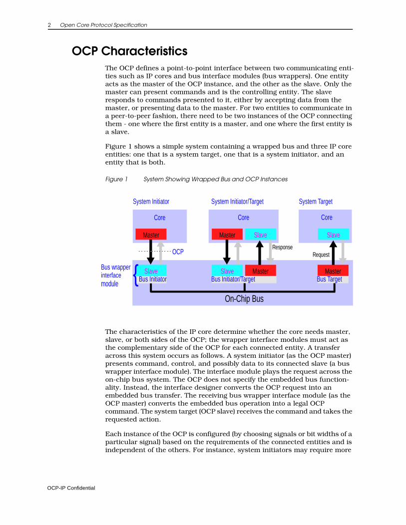
Figure 1 shows a simple system containing a wrapped bus and three IP core entities: one that is a system target, one that is a system initiator, and an entity that is both.
Figure 1 System Showing Wrapped Bus and OCP Instances
The characteristics of the IP core determine whether the core needs master, slave, or both sides of the OCP; the wrapper interface modules must act as the complementary side of the OCP for each connected entity. A transfer across this system occurs as follows. A system initiator (as the OCP master) presents command, control, and possibly data to its connected slave (a bus wrapper interface module). The interface module plays the request across the on-chip bus system. The OCP does not specify the embedded bus function-ality. Instead, the interface designer converts the OCP request into an embedded bus transfer. The receiving bus wrapper interface module (as the OCP master) converts the embedded bus operation into a legal OCP command. The system target (OCP slave) receives the command and takes the requested action.
Each instance of the OCP is configured (by choosing signals or bit widths of a particular signal) based on the requirements of the connected entities and is independent of the others. For instance, system initiators may require more
Core Core Core
On-Chip Bus
Master Master
MasterSlave Slave Master
Slave Slave
OCP RequestResponse
System Initiator/Target System TargetSystem Initiator
Bus Initiator Bus Initiator/Target Bus Target
Bus wrapperinterfacemodule
{
OCP-IP Confidential
Overview 3
address bits in their OCP instances than do the system targets; the extra address bits might be used by the embedded bus to select which bus target is addressed by the system initiator.
The OCP is flexible. There are several useful models for how existing IP cores communicate with one another. Some employ pipelining to improve band-width and latency characteristics. Others use multiple-cycle access models, where signals are held static for several clock cycles to simplify timing anal-ysis and reduce implementation area. Support for this wide range of behavior is possible through the use of synchronous handshaking signals that allow both the master and slave to control when signals are allowed to change.
ComplianceFor a core to be considered OCP compliant, it must satisfy the following conditions:
1. The core must include at least one OCP interface.
2. The core and OCP interfaces must be described using an RTL configuration file with the syntax specified in Chapter 6 on page 69.
3. Each OCP interface on the core must:
• Comply with all aspects of the OCP interface specification
• Have its timing described using a synthesis configuration file following the syntax specified in Chapter 7 on page 81.
4. The following practices are recommended but not required:
a. Each non-OCP interface on the core should:
Be described using an interface configuration file with the syntax specified in Chapter 5 on page 63.
Have its timing described using a synthesis configuration file with the syntax specified in Chapter 7 on page 81.
b. A performance report as specified in Chapter 13 on page 203 (or an equivalent report) should be included for the core.
OCP-IP Confidential


Part I Specification

2 Theory of Operation
The Open Core Protocol interface addresses communications between the functional units (or IP cores) that comprise a system on a chip. The OCP provides independence from bus protocols without having to sacrifice high-performance access to on-chip interconnects. By designing to the interface boundary defined by the OCP, you can develop reusable IP cores without regard for the ultimate target system.
Given the wide range of IP core functionality, performance and interface requirements, a fixed definition interface protocol cannot address the full spectrum of requirements. The need to support verification and test require-ments adds an even higher level of complexity to the interface. To address this spectrum of interface definitions, the OCP defines a highly configurable inter-face. The OCP’s structured methodology includes all of the signals required to describe an IP cores’ communications including data flow, control, and veri-fication and test signals.
This chapter provides an overview of the concepts behind the Open Core Protocol, introduces the terminology used to describe the interface and offers a high-level view of the protocol.
OCP-IP Confidential
8 Open Core Protocol Specification
Point-to-Point Synchronous InterfaceTo simplify timing analysis, physical design, and general comprehension, the OCP is composed of uni-directional signals driven with respect to, and sampled by the rising edge of the OCP clock. The OCP is fully synchronous and contains no multi-cycle timing paths. All signals other than the clock are strictly point-to-point.
Bus IndependenceA core utilizing the OCP can be interfaced to any bus. A test of any bus-inde-pendent interface is to connect a master to a slave without an intervening on-chip bus. This test not only drives the specification towards a fully symmetric interface but helps to clarify other issues. For instance, device selection tech-niques vary greatly among on-chip buses. Some use address decoders. Others generate independent device select signals (analogous to a board level chip select). This complexity should be hidden from IP cores, especially since in the directly-connected case there is no decode/selection logic. OCP-compliant slaves receive device selection information integrated into the basic command field.
Arbitration schemes vary widely. Since there is virtually no arbitration in the directly-connected case, arbitration for any shared resource is the sole responsibility of the logic on the bus side of the OCP. This permits OCP-compliant masters to pass a command field across the OCP that the bus inter-face logic converts into an arbitration request sequence.
CommandsThere are two basic commands, Read and Write and five command exten-sions. The WriteNonPost and Broadcast commands have semantics that are similar to the Write command. A WriteNonPost explicitly instructs the slave not to post a write. For the Broadcast command, the master indicates that it is attempting to write to several or all remote target devices that are connected on the other side of the slave. As such, Broadcast is typically useful only for slaves that are in turn a master on another communication medium (such as an attached bus).
The other command extensions, ReadExclusive, ReadLinked and WriteCondi-tional, are used for synchronization between system initiators. ReadExclusive is paired with Write or WriteNonPost, and has blocking semantics. ReadLinked, used in conjunction with WriteConditional has non-blocking (lazy) semantics. These synchronization primitives correspond to those avail-able natively in the instruction sets of different processors.
OCP-IP Confidential
Theory of Operation 9
Address/DataWide widths, characteristic of shared on-chip address and data buses, make tuning the OCP address and data widths essential for area-efficient imple-mentation. Only those address bits that are significant to the IP core should cross the OCP to the slave. The OCP address space is flat and composed of 8-bit bytes (octets).
To increase transfer efficiencies, many IP cores have data field widths signifi-cantly greater than an octet. The OCP supports a configurable data width to allow multiple bytes to be transferred simultaneously. The OCP refers to the chosen data field width as the word size of the OCP. The term word is used in the traditional computer system context; that is, a word is the natural transfer unit of the block. OCP supports word sizes of power-of-two and non-power-of-two as would be needed for a 12-bit DSP core. The OCP address is a byte address that is word aligned.
Transfers of less than a full word of data are supported by providing byte enable information that specifies which octets are to be transferred. Byte enables are linked to specific data bits (byte lanes). Byte lanes are not associ-ated with particular byte addresses. This makes the OCP endian-neutral, able to support both big and little-endian cores.
PipeliningThe OCP allows pipelining of transfers. To support this feature, the return of read data and the provision of write data may be delayed after the presenta-tion of the associated request.
ResponseThe OCP separates requests from responses. A slave can accept a command request from a master on one cycle and respond in a later cycle. The division of request from response permits pipelining. The OCP provides the option of having responses for Write commands, or completing them immediately without an explicit response.
BurstTo provide high transfer efficiency, burst support is essential for many IP cores. The extended OCP supports annotation of transfers with burst infor-mation. Bursts can either include addressing information for each successive command (which simplifies the requirements for address sequencing/burst count processing in the slave), or include addressing information only once for the entire burst.
In-band InformationCores can pass core-specific information in-band in company with the other information being exchanged. In-band extensions exist for requests and responses, as well as read and write data. A typical use of in-band extensions is to pass cacheable information or data parity.
OCP-IP Confidential
10 Open Core Protocol Specification
TagsTags are available in the OCP interface to control the ordering of responses. Without tags, a slave must return responses in the order that the requests were issued by the master. Similarly, writes must be committed in order. With the addition of tags, responses can be returned out-of-order, and write data can be committed out-of-order with respect to requests, as long as the trans-actions target different addresses. The tag links the response back to the original request.
Tagging is useful when a master core such as a processor can handle out-of-order return, because it allows a slave core such as a DRAM controller to service requests in the order that is most convenient, rather than the order in which requests were sent by the master.
Out-of-order request and response delivery can also be enabled using multiple threads. The major differences between threads and tags are that threads can have independent flow control for each thread and have no ordering rules for transactions on different threads. Tags, on the other hand, exist within a single thread and are restricted to shared flow control. Tagged transactions cannot be re-ordered with respect to overlapping addresses. Implementing independent flow control requires independent buffering for each thread, leading to more complex implementations. Tags enable lower overhead implementations for out-of-order return of responses at the expense of some concurrency.
Threads and ConnectionsTo support concurrency and out-of-order processing of transfers, the extended OCP supports the notion of multiple threads. Transactions within different threads have no ordering requirements, and independent flow control from one another. Within a single thread of data flow, all OCP trans-fers must remain ordered unless tags are in use. Transfers within a single thread must remain ordered unless tags are in use. The concepts of threads and tags are hierarchical: each thread has its own flow control, and ordering within a thread either follows the request order strictly, or is governed by tags.
While the notion of a thread is a local concept between a master and a slave communicating over an OCP, it is possible to globally pass thread information from initiator to target using connection identifiers. Connection information helps to identify the initiator and determine priorities or access permissions at the target.
Interrupts, Errors, and other Sideband SignalingWhile moving data between devices is a central requirement of on-chip communication systems, other types of communications are also important. Different types of control signaling are required to coordinate data transfers (for instance, high-level flow control) or signal system events (such as inter-rupts). Dedicated point-to-point data communication is sometimes required. Many devices also require the ability to notify the system of errors that may be unrelated to address/data transfers.
OCP-IP Confidential
Theory of Operation 11
The OCP refers to all such communication as sideband (or out-of-band) signaling, since it is not directly related to the protocol state machines of the dataflow portion of the OCP. The OCP provides support for such signals through sideband signaling extensions.
Errors are reported across the OCP using two mechanisms. The error response code in the response field describes errors resulting from OCP trans-fers that provide responses. Write-type commands without responses cannot use the in-band reporting mechanism. The second method for reporting errors across the OCP uses out-of band error fields. These signals report more generic sideband errors, including those associated with posted write commands.
OCP-IP Confidential

3 Signals and Encoding
OCP interface signals are grouped into dataflow, sideband, and test signals. The dataflow signals are divided into basic signals, simple extensions, burst extensions, tag extensions, and thread extensions. A small set of the signals from the basic dataflow group is required in all OCP configurations. Optional signals can be configured to support additional core communication require-ments. All sideband and test signals are optional.
The OCP is a synchronous interface with a single clock signal. All OCP signals are driven with respect to, and sampled by, the rising edge of the OCP clock. Except for clock, OCP signals are strictly point-to-point and uni-directional. The complete set of OCP signals is shown in Figure 4 on page 32.
OCP-IP Confidential
14 Open Core Protocol Specification
Dataflow SignalsThe dataflow signals consist of a small set of required signals and a number of optional signals that can be configured to support additional core commu-nication requirements. The dataflow signals are grouped into basic signals, simple extensions (options such as byte enables and in-band information), burst extensions (support for bursting), tag extensions (re-ordering support), and thread extensions (multi-threading support).
The naming conventions for dataflow signals use the prefix M for signals driven by the OCP master and S for signals driven by the OCP slave.
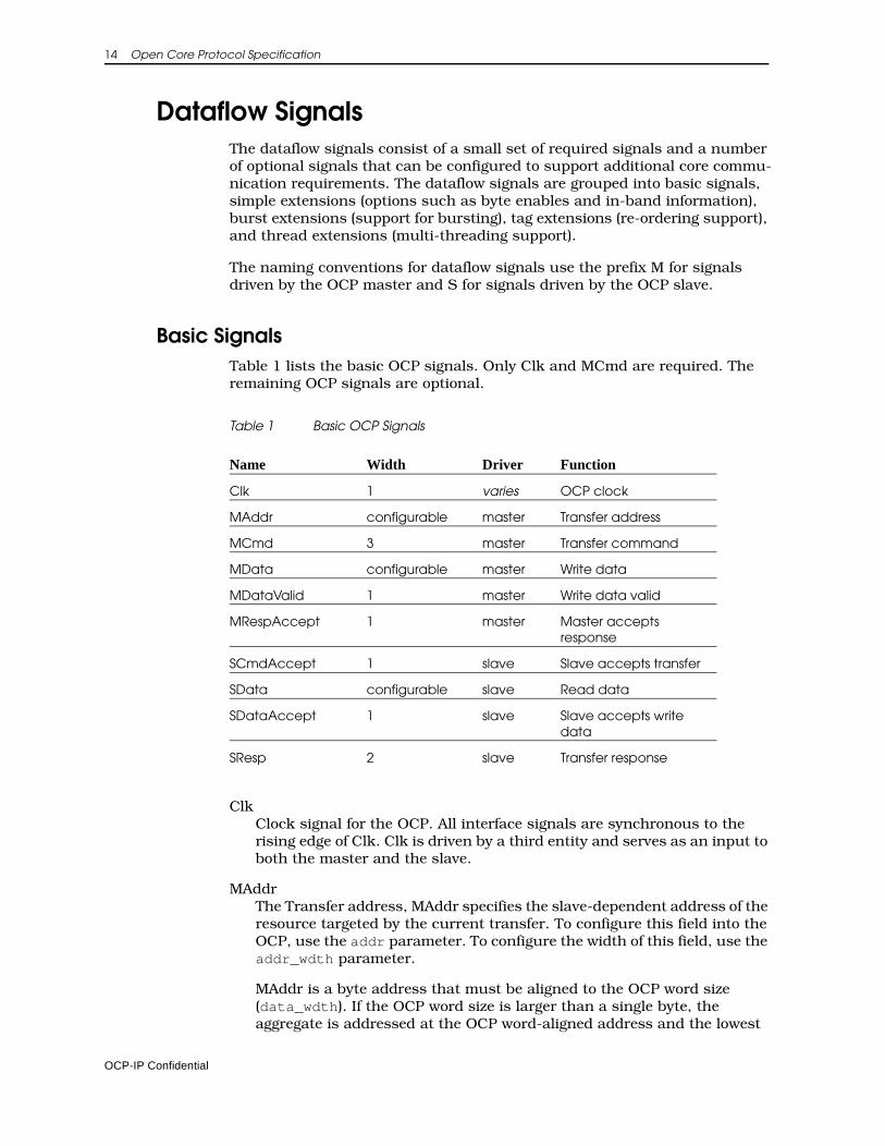
Basic SignalsTable 1 lists the basic OCP signals. Only Clk and MCmd are required. The remaining OCP signals are optional.
Table 1 Basic OCP Signals
ClkClock signal for the OCP. All interface signals are synchronous to the rising edge of Clk. Clk is driven by a third entity and serves as an input to both the master and the slave.
MAddrThe Transfer address, MAddr specifies the slave-dependent address of the resource targeted by the current transfer. To configure this field into the OCP, use the addr parameter. To configure the width of this field, use the addr_wdth parameter.
MAddr is a byte address that must be aligned to the OCP word size (data_wdth). If the OCP word size is larger than a single byte, the aggregate is addressed at the OCP word-aligned address and the lowest
Name Width Driver Function
Clk 1 varies OCP clock
MAddr configurable master Transfer address
MCmd 3 master Transfer command
MData configurable master Write data
MDataValid 1 master Write data valid
MRespAccept 1 master Master accepts response
SCmdAccept 1 slave Slave accepts transfer
SData configurable slave Read data
SDataAccept 1 slave Slave accepts write data
SResp 2 slave Transfer response
OCP-IP Confidential
Signals and Encoding 15
order address bits are hardwired to 0. If the OCP word size is not a power-of-2, the address is the same as it would be for an OCP interface with a word size equal to the next larger power-of-2.
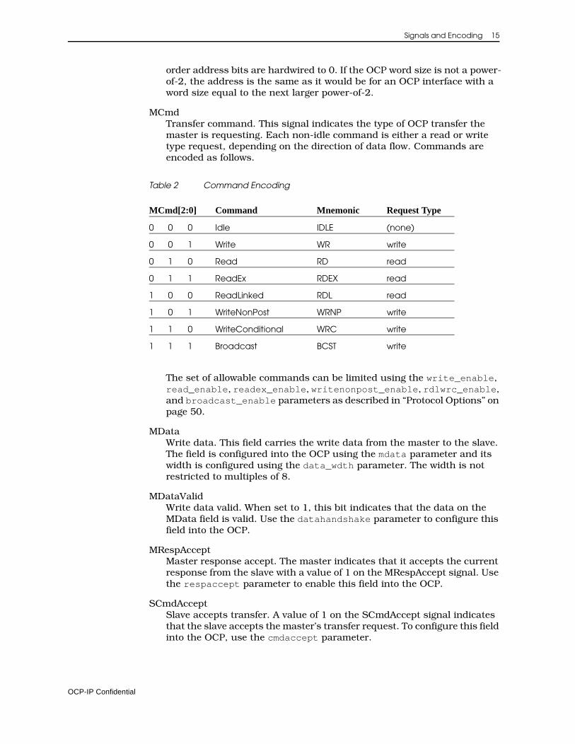
MCmdTransfer command. This signal indicates the type of OCP transfer the master is requesting. Each non-idle command is either a read or write type request, depending on the direction of data flow. Commands are encoded as follows.
Table 2 Command Encoding
The set of allowable commands can be limited using the write_enable, read_enable, readex_enable, writenonpost_enable, rdlwrc_enable, and broadcast_enable parameters as described in “Protocol Options” on page 50.
MDataWrite data. This field carries the write data from the master to the slave. The field is configured into the OCP using the mdata parameter and its width is configured using the data_wdth parameter. The width is not restricted to multiples of 8.
MDataValidWrite data valid. When set to 1, this bit indicates that the data on the MData field is valid. Use the datahandshake parameter to configure this field into the OCP.
MRespAcceptMaster response accept. The master indicates that it accepts the current response from the slave with a value of 1 on the MRespAccept signal. Use the respaccept parameter to enable this field into the OCP.
SCmdAcceptSlave accepts transfer. A value of 1 on the SCmdAccept signal indicates that the slave accepts the master’s transfer request. To configure this field into the OCP, use the cmdaccept parameter.
MCmd[2:0] Command Mnemonic Request Type
0 0 0 Idle IDLE (none)
0 0 1 Write WR write
0 1 0 Read RD read
0 1 1 ReadEx RDEX read
1 0 0 ReadLinked RDL read
1 0 1 WriteNonPost WRNP write
1 1 0 WriteConditional WRC write
1 1 1 Broadcast BCST write
OCP-IP Confidential
16 Open Core Protocol Specification
SDataThis field carries the requested read data from the slave to the master. The field is configured into the OCP using the sdata parameter and its width is configured using the data_wdth parameter. The width is not restricted to multiples of 8.
SDataAcceptSlave accepts write data. The slave indicates that it accepts pipelined write data from the master with a value of 1 on SDataAccept. This signal is meaningful only when datahandshake is in use. Use the dataaccept parameter to configure this field into the OCP.
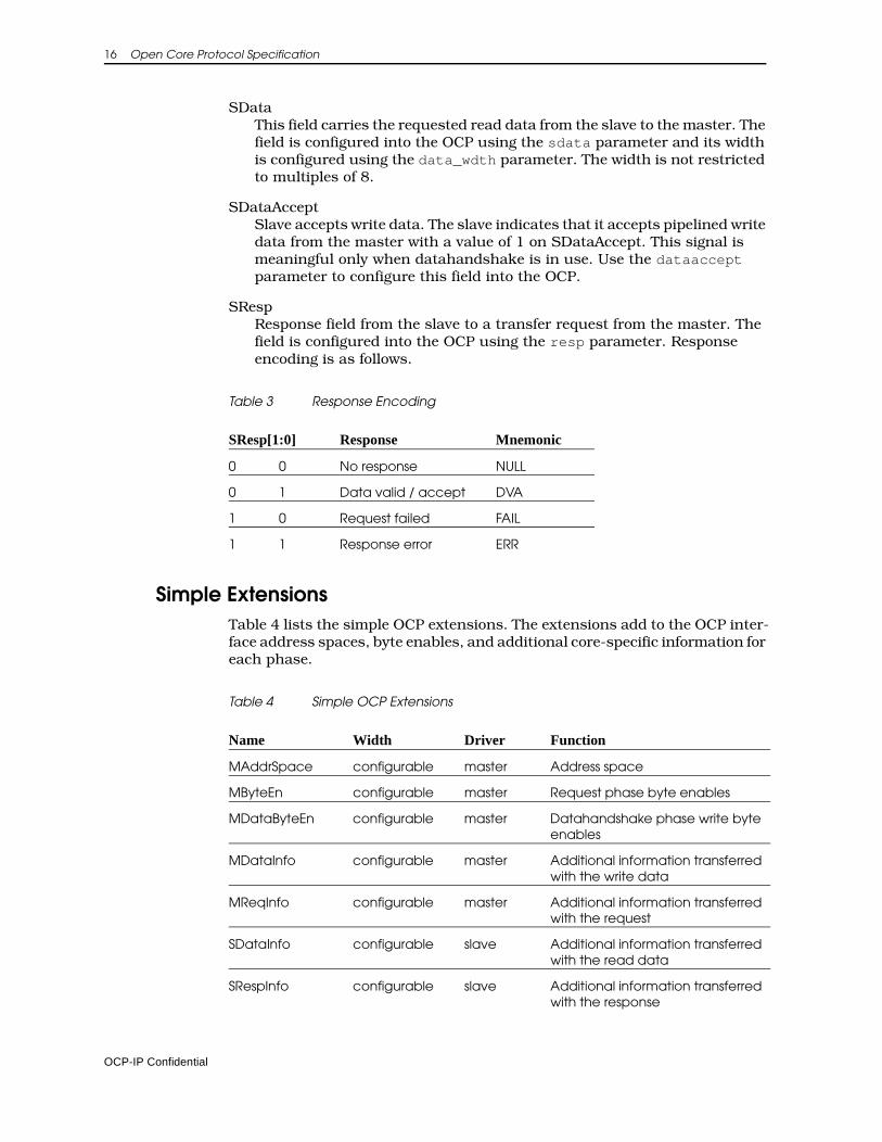
SRespResponse field from the slave to a transfer request from the master. The field is configured into the OCP using the resp parameter. Response encoding is as follows.
Table 3 Response Encoding
Simple ExtensionsTable 4 lists the simple OCP extensions. The extensions add to the OCP inter-face address spaces, byte enables, and additional core-specific information for each phase.
Table 4 Simple OCP Extensions
SResp[1:0] Response Mnemonic
0 0 No response NULL
0 1 Data valid / accept DVA
1 0 Request failed FAIL
1 1 Response error ERR
Name Width Driver Function
MAddrSpace configurable master Address space
MByteEn configurable master Request phase byte enables
MDataByteEn configurable master Datahandshake phase write byte enables
MDataInfo configurable master Additional information transferred with the write data
MReqInfo configurable master Additional information transferred with the request
SDataInfo configurable slave Additional information transferred with the read data
SRespInfo configurable slave Additional information transferred with the response
OCP-IP Confidential
Signals and Encoding 17
MAddrSpaceThis field specifies the address space and is an extension of the MAddr field that is used to indicate the address region of a transfer. Examples of address regions are the register space versus the regular memory space of a slave or the user versus supervisor space for a master.
The MAddrSpace field is configured into the OCP using the addrspace parameter. The width of the MAddrSpace field is configured with the addrspace_wdth parameter. While the encoding of the MAddrSpace field is core-specific, it is recommended that slaves use 0 to indicate the internal register space.
MByteEnByte enables. This field indicates which bytes within the OCP word are part of the current transfer. See “Partial Word Transfers” on page 43 for more detail on request and datahandshake phase byte enables and their relationship. There is one bit in MByteEn for each byte in the OCP word. Setting MByteEn[n] to 1 indicates that the byte associated with data wires [(8n + 7):8n] should be transferred. The MByteEn field is configured into the OCP using the byteen parameter and is allowed only if data_wdth is a multiple of 8 (that is, the data width is an integer number of bytes).
The allowable patterns on MByteEn can be limited using the force_aligned parameter as described on page 51.
MDataByteEnWrite byte enables. This field indicates which bytes within the OCP word are part of the current write transfer. See “Partial Word Transfers” on page 43 for more detail on request and datahandshake phase byte enables and their relationship. There is one bit in MDataByteEn for each byte in the OCP word. Setting MDataByteEn[n] to 1 indicates that the byte associated with MData wires [(8n + 7):8n] should be transferred. The MDataByteEn field is configured into the OCP using the mdatabyteen parameter. Setting mdatabyteen to 1 is only allowed if datahandshake_enable is 1, and only if data_wdth is a multiple of 8 (that is, the data width is an integer number of bytes).
The allowable patterns on MDataByteEn can be limited using the force_aligned parameter as described on page 51.
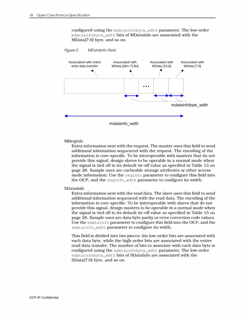
MDataInfoExtra information sent with the write data. The master uses this field to send additional information sequenced with the write data. The encoding of the information is core-specific. To be interoperable with masters that do not provide this signal, design slaves to be operable in a normal mode when the signal is tied off to its default tie-off value as specified in Table 13 on page 28. Sample uses are data byte parity or error correction code values. Use the mdatainfo parameter to configure this field into the OCP, and the mdatainfo_wdth parameter to configure its width.
This field is divided in two: the low-order bits are associated with each data byte, while the high-order bits are associated with the entire write data transfer. The number of bits to associate with each data byte is
OCP-IP Confidential
18 Open Core Protocol Specification
configured using the mdatainfobyte_wdth parameter. The low-order mdatainfobyte_wdth bits of MDataInfo are associated with the MData[7:0] byte, and so on.
Figure 2 MDataInfo Field
MReqInfoExtra information sent with the request. The master uses this field to send additional information sequenced with the request. The encoding of the information is core-specific. To be interoperable with masters that do not provide this signal, design slaves to be operable in a normal mode when the signal is tied off to its default tie-off value as specified in Table 13 on page 28. Sample uses are cacheable storage attributes or other access mode information. Use the reqinfo parameter to configure this field into the OCP, and the reqinfo_wdth parameter to configure its width.
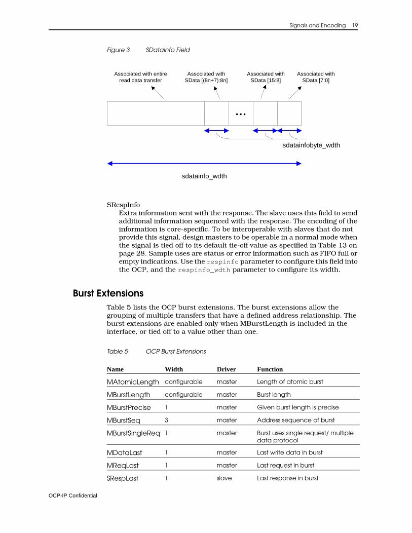
SDataInfoExtra information sent with the read data. The slave uses this field to send additional information sequenced with the read data. The encoding of the information is core-specific. To be interoperable with slaves that do not provide this signal, design masters to be operable in a normal mode when the signal is tied off to its default tie-off value as specified in Table 13 on page 28. Sample uses are data byte parity or error correction code values. Use the sdatainfo parameter to configure this field into the OCP, and the sdatainfo_wdth parameter to configure its width.
This field is divided into two pieces: the low-order bits are associated with each data byte, while the high-order bits are associated with the entire read data transfer. The number of bits to associate with each data byte is configured using the sdatainfobyte_wdth parameter. The low-order sdatainfobyte_wdth bits of SDataInfo are associated with the SData[7:0] byte, and so on.
���
mdatainfo_wdth
mdatainfobyte_wdth
Associated with entirewrite data transfer
Associated withMData [15:8]
Associated withMData [7:0]
Associated withMData [(8n+7):8n]
OCP-IP Confidential
Signals and Encoding 19
Figure 3 SDataInfo Field
SRespInfoExtra information sent with the response. The slave uses this field to send additional information sequenced with the response. The encoding of the information is core-specific. To be interoperable with slaves that do not provide this signal, design masters to be operable in a normal mode when the signal is tied off to its default tie-off value as specified in Table 13 on page 28. Sample uses are status or error information such as FIFO full or empty indications. Use the respinfo parameter to configure this field into the OCP, and the respinfo_wdth parameter to configure its width.
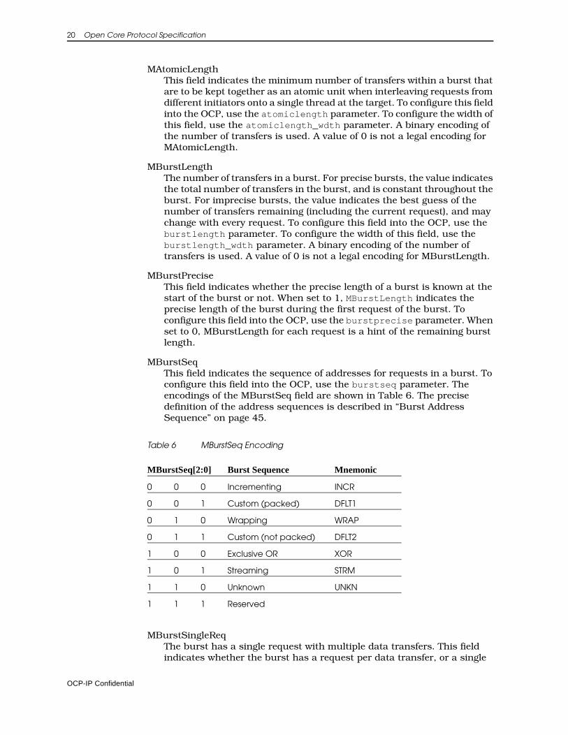
Burst ExtensionsTable 5 lists the OCP burst extensions. The burst extensions allow the grouping of multiple transfers that have a defined address relationship. The burst extensions are enabled only when MBurstLength is included in the interface, or tied off to a value other than one.
Table 5 OCP Burst Extensions
Name Width Driver Function
MAtomicLength configurable master Length of atomic burst
MBurstLength configurable master Burst length
MBurstPrecise 1 master Given burst length is precise
MBurstSeq 3 master Address sequence of burst
MBurstSingleReq 1 master Burst uses single request/ multiple data protocol
MDataLast 1 master Last write data in burst
MReqLast 1 master Last request in burst
SRespLast 1 slave Last response in burst
���
sdatainfo_wdth
sdatainfobyte_wdth
Associated with entireread data transfer
Associated withSData [15:8]
Associated withSData [7:0]
Associated withSData [(8n+7):8n]
OCP-IP Confidential
20 Open Core Protocol Specification
MAtomicLengthThis field indicates the minimum number of transfers within a burst that are to be kept together as an atomic unit when interleaving requests from different initiators onto a single thread at the target. To configure this field into the OCP, use the atomiclength parameter. To configure the width of this field, use the atomiclength_wdth parameter. A binary encoding of the number of transfers is used. A value of 0 is not a legal encoding for MAtomicLength.
MBurstLengthThe number of transfers in a burst. For precise bursts, the value indicates the total number of transfers in the burst, and is constant throughout the burst. For imprecise bursts, the value indicates the best guess of the number of transfers remaining (including the current request), and may change with every request. To configure this field into the OCP, use the burstlength parameter. To configure the width of this field, use the burstlength_wdth parameter. A binary encoding of the number of transfers is used. A value of 0 is not a legal encoding for MBurstLength.
MBurstPreciseThis field indicates whether the precise length of a burst is known at the start of the burst or not. When set to 1, MBurstLength indicates the precise length of the burst during the first request of the burst. To configure this field into the OCP, use the burstprecise parameter. When set to 0, MBurstLength for each request is a hint of the remaining burst length.
MBurstSeqThis field indicates the sequence of addresses for requests in a burst. To configure this field into the OCP, use the burstseq parameter. The encodings of the MBurstSeq field are shown in Table 6. The precise definition of the address sequences is described in “Burst Address Sequence” on page 45.
Table 6 MBurstSeq Encoding
MBurstSingleReqThe burst has a single request with multiple data transfers. This field indicates whether the burst has a request per data transfer, or a single
MBurstSeq[2:0] Burst Sequence Mnemonic
0 0 0 Incrementing INCR
0 0 1 Custom (packed) DFLT1
0 1 0 Wrapping WRAP
0 1 1 Custom (not packed) DFLT2
1 0 0 Exclusive OR XOR
1 0 1 Streaming STRM
1 1 0 Unknown UNKN
1 1 1 Reserved
OCP-IP Confidential
Signals and Encoding 21
request for all data transfers. To configure this field into the OCP, use the burstsinglereq parameter. When this field is set to 0, there is a one-to-one association of requests to data transfers; when set to 1, there is a single request for all data transfers in the burst.
MDataLastLast write data in a burst. This field indicates whether the current write data transfer is the last in a burst. To configure this field into the OCP, use the datalast parameter with datahandshake set to 1. When this field is set to 0, more write data transfers are coming for the burst; when set to 1, the current write data transfer is the last in the burst.
MReqLastLast request in a burst. This field indicates whether the current request is the last in this burst. To configure this field into the OCP, use the reqlast parameter. When this field is set to 0, more requests are coming for this burst; when set to 1, the current request is the last in the burst.
SRespLastLast response in a burst. This field indicates whether the current response is the last in this burst. To configure this field into the OCP, use the resplast parameter. When the field is set to 0, more responses are coming for this burst; when set to 1, the current response is the last in the burst.
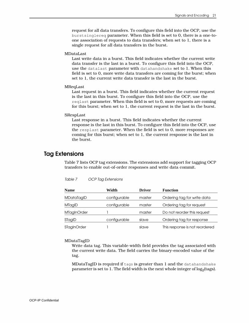
Tag ExtensionsTable 7 lists OCP tag extensions. The extensions add support for tagging OCP transfers to enable out-of-order responses and write data commit.
Table 7 OCP Tag Extensions
MDataTagIDWrite data tag. This variable-width field provides the tag associated with the current write data. The field carries the binary-encoded value of the tag.
MDataTagID is required if tags is greater than 1 and the datahandshake parameter is set to 1. The field width is the next whole integer of log2(tags).
Name Width Driver Function
MDataTagID configurable master Ordering tag for write data
MTagID configurable master Ordering tag for request
MTagInOrder 1 master Do not reorder this request
STagID configurable slave Ordering tag for response
STagInOrder 1 slave This response is not reordered
OCP-IP Confidential
22 Open Core Protocol Specification
MTagIDRequest tag. This variable-width field provides the tag associated with the current transfer request. If tags is greater than 1, this field is enabled. The field width is the next whole integer of log2(tags).
MTagInOrderAssertion of this single-bit field indicates that the current request should not be reordered with respect to other requests that had this field asserted. This field is enabled by the taginorder parameter. Both MTagInOrder and STagInOrder are present in the interface, or else neither may be present.
STagIDResponse tag. This variable-width field provides the tag associated with the current transfer response. This field is enabled if tags is greater than 1, and the resp parameter is set to 1. The field width is the next whole integer of log2(tags).
STagInOrderAssertion of this single-bit field indicates that the current response is associated with an in-order request and was not reordered with respect to other requests that had MTagInOrder asserted. This field is enabled if both the taginorder parameter is set to 1 and the resp parameter is set to 1.
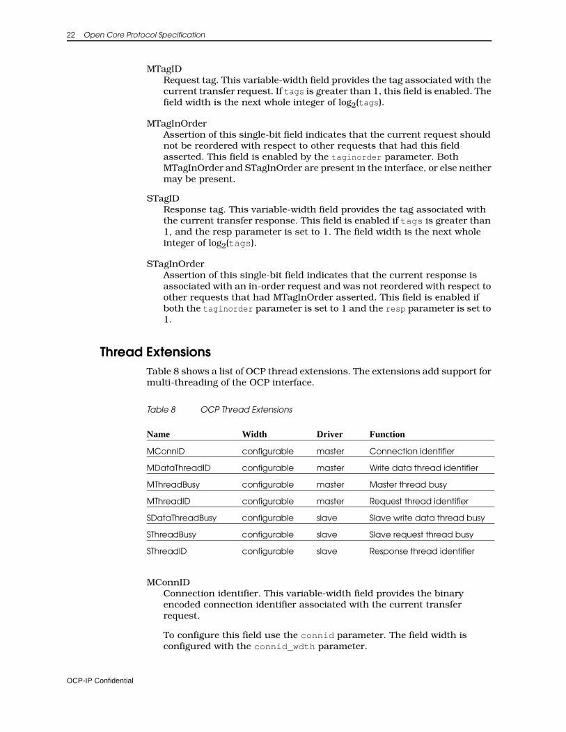
Thread ExtensionsTable 8 shows a list of OCP thread extensions. The extensions add support for multi-threading of the OCP interface.
Table 8 OCP Thread Extensions
MConnIDConnection identifier. This variable-width field provides the binary encoded connection identifier associated with the current transfer request.
To configure this field use the connid parameter. The field width is configured with the connid_wdth parameter.
Name Width Driver Function
MConnID configurable master Connection identifier
MDataThreadID configurable master Write data thread identifier
MThreadBusy configurable master Master thread busy
MThreadID configurable master Request thread identifier
SDataThreadBusy configurable slave Slave write data thread busy
SThreadBusy configurable slave Slave request thread busy
SThreadID configurable slave Response thread identifier
OCP-IP Confidential
Signals and Encoding 23
MDataThreadIDWrite data thread identifier. This variable-width field provides the thread identifier associated with the current write data. The field carries the binary-encoded value of the thread identifier.
MDataThreadID is required if threads is greater than 1 and the datahandshake parameter is set to 1. MDataThreadID has the same width as MThreadID and SThreadID.
MThreadBusyMaster thread busy. The master notifies the slave that it cannot accept any responses associated with certain threads. The MThreadBusy field is a vector (one bit per thread). A value of 1 on any given bit indicates that the thread associated with that bit is busy. Bit 0 corresponds to thread 0, and so on. The width of the field is set using the threads parameter. It is legal to enable a one-bit MThreadBusy interface for a single-threaded OCP. To configure this field, use the mthreadbusy parameter.
MThreadIDRequest thread identifier. This variable-width field provides the thread identifier associated with the current transfer request. If threads is greater than 1, this field is enabled. The field width is the next whole integer of log2(threads).
SDataThreadBusySlave write data thread busy. The slave notifies the master that it cannot accept any new datahandshake phases associated with certain threads. The SDataThreadBusy field is a vector, one bit per thread. A value of 1 on any given bit indicates that the thread associated with that bit is busy. Bit 0 corresponds to thread 0, and so on.
The width of the field is set using the threads parameter. It is legal to enable a one-bit SDataThreadBusy interface for a single-threaded OCP. To configure this field, use the sdatathreadbusy parameter.
SThreadIDResponse thread identifier. This variable-width field provides the thread identifier associated with the current transfer response. This field is enabled if threads is greater than 1 and the resp parameter is set to 1. The field width is the next whole integer of log2(threads).
SThreadBusySlave thread busy. The slave notifies the master that it cannot accept any new requests associated with certain threads. The SThreadBusy field is a vector, one bit per thread. A value of 1 on any given bit indicates that the thread associated with that bit is busy. Bit 0 corresponds to thread 0, and so on. The width of the field is set using the threads parameter. It is legal to enable a one-bit SThreadBusy interface for a single-threaded OCP. To configure this field, use the sthreadbusy parameter.
OCP-IP Confidential
24 Open Core Protocol Specification
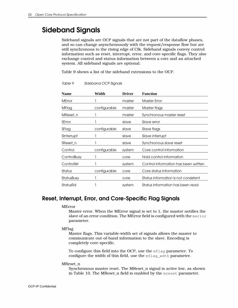
Sideband SignalsSideband signals are OCP signals that are not part of the dataflow phases, and so can change asynchronously with the request/response flow but are still synchronous to the rising edge of Clk. Sideband signals convey control information such as reset, interrupt, error, and core-specific flags. They also exchange control and status information between a core and an attached system. All sideband signals are optional.
Table 9 shows a list of the sideband extensions to the OCP.
Table 9 Sideband OCP Signals
Reset, Interrupt, Error, and Core-Specific Flag SignalsMError
Master error. When the MError signal is set to 1, the master notifies the slave of an error condition. The MError field is configured with the merror parameter.
MFlagMaster flags. This variable-width set of signals allows the master to communicate out-of-band information to the slave. Encoding is completely core-specific.
To configure this field into the OCP, use the mflag parameter. To configure the width of this field, use the mflag_wdth parameter.
MReset_nSynchronous master reset. The MReset_n signal is active low, as shown in Table 10. The MReset_n field is enabled by the mreset parameter.
Name Width Driver Function
MError 1 master Master Error
MFlag configurable master Master flags
MReset_n 1 master Synchronous master reset
SError 1 slave Slave error
SFlag configurable slave Slave flags
SInterrupt 1 slave Slave interrupt
SReset_n 1 slave Synchronous slave reset
Control configurable system Core control information
ControlBusy 1 core Hold control information
ControlWr 1 system Control information has been written
Status configurable core Core status information
StatusBusy 1 core Status information is not consistent
StatusRd 1 system Status information has been read
OCP-IP Confidential
Signals and Encoding 25
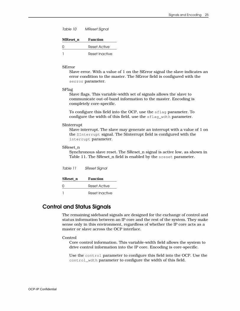
Table 10 MReset Signal
SErrorSlave error. With a value of 1 on the SError signal the slave indicates an error condition to the master. The SError field is configured with the serror parameter.
SFlagSlave flags. This variable-width set of signals allows the slave to communicate out-of-band information to the master. Encoding is completely core-specific.
To configure this field into the OCP, use the sflag parameter. To configure the width of this field, use the sflag_wdth parameter.
SInterruptSlave interrupt. The slave may generate an interrupt with a value of 1 on the SInterrupt signal. The SInterrupt field is configured with the interrupt parameter.
SReset_nSynchronous slave reset. The SReset_n signal is active low, as shown in Table 11. The SReset_n field is enabled by the sreset parameter.
Table 11 SReset Signal
Control and Status SignalsThe remaining sideband signals are designed for the exchange of control and status information between an IP core and the rest of the system. They make sense only in this environment, regardless of whether the IP core acts as a master or slave across the OCP interface.
ControlCore control information. This variable-width field allows the system to drive control information into the IP core. Encoding is core-specific.
Use the control parameter to configure this field into the OCP. Use the control_wdth parameter to configure the width of this field.
MReset_n Function
0 Reset Active
1 Reset Inactive
SReset_n Function
0 Reset Active
1 Reset Inactive
OCP-IP Confidential
26 Open Core Protocol Specification
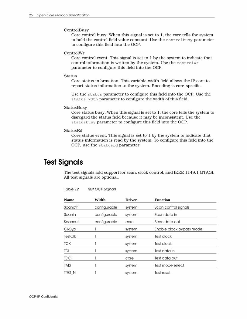
ControlBusyCore control busy. When this signal is set to 1, the core tells the system to hold the control field value constant. Use the controlbusy parameter to configure this field into the OCP.
ControlWrCore control event. This signal is set to 1 by the system to indicate that control information is written by the system. Use the controlwr parameter to configure this field into the OCP.
StatusCore status information. This variable-width field allows the IP core to report status information to the system. Encoding is core-specific.
Use the status parameter to configure this field into the OCP. Use the status_wdth parameter to configure the width of this field.
StatusBusyCore status busy. When this signal is set to 1, the core tells the system to disregard the status field because it may be inconsistent. Use the statusbusy parameter to configure this field into the OCP.
StatusRdCore status event. This signal is set to 1 by the system to indicate that status information is read by the system. To configure this field into the OCP, use the statusrd parameter.
Test SignalsThe test signals add support for scan, clock control, and IEEE 1149.1 (JTAG). All test signals are optional.
Table 12 Test OCP Signals
Name Width Driver Function
Scanctrl configurable system Scan control signals
Scanin configurable system Scan data in
Scanout configurable core Scan data out
ClkByp 1 system Enable clock bypass mode
TestClk 1 system Test clock
TCK 1 system Test clock
TDI 1 system Test data in
TDO 1 core Test data out
TMS 1 system Test mode select
TRST_N 1 system Test reset
OCP-IP Confidential
Signals and Encoding 27
Scan InterfaceThe Scanctrl, Scanin, and Scanout signals together form a scan interface into a given IP core.
ScanctrlScan mode control signals. Use this variable width field to control the scan mode of the core. Set scanport to 1 to configure this field into the OCP interface. Use the scanctrl_wdth parameter to configure the width of this field.
ScaninScan data in for a core’s scan chains. Use the scanport parameter, to configure this field into the OCP interface and scanport_wdth to control its width.
ScanoutScan data out from the core’s scan chains. Use the scanport parameter to configure this field into the OCP interface and scanport_wdth to control its width.
Clock Control InterfaceThe ClkByp and TestClk signals together form the clock control interface into a given IP core. This interface is used to control the core’s clocks during scan operation.
ClkBypEnable clock bypass signal. When set to 1, this signal instructs the core to bypass the external clock source and use TestClk instead. Use the clkctrl_enable parameter to configure this signal into the OCP interface.
TestClkA gated test clock. This clock becomes the source clock when ClkByp is asserted during scan operations. Use the clkctrl_enable parameter to configure this signal into the OCP interface.
Debug and Test InterfaceThe TCK, TDI, TDO, TMS, and TRST_N signals together form an IEEE 1149 debug and test interface for the OCP.
TCKTest clock as defined by IEEE 1149.1. Use the jtag_enable parameter to add this signal to the OCP interface.
TDITest data in as defined by IEEE 1149.1. Use the jtag_enable parameter to add this signal to the OCP interface.
TDOTest data out as defined by IEEE 1149.1. Use the jtag_enable parameter to add this signal to the OCP interface.
OCP-IP Confidential
28 Open Core Protocol Specification
TMSTest mode select as defined by IEEE 1149.1. Use the jtag_enable parameter to add this signal to the OCP interface.
TRST_NTest logic reset signal. This is an asynchronous active low reset as defined by IEEE 1149.1. Use the jtagtrst_enable parameter to add this signal to the OCP interface.
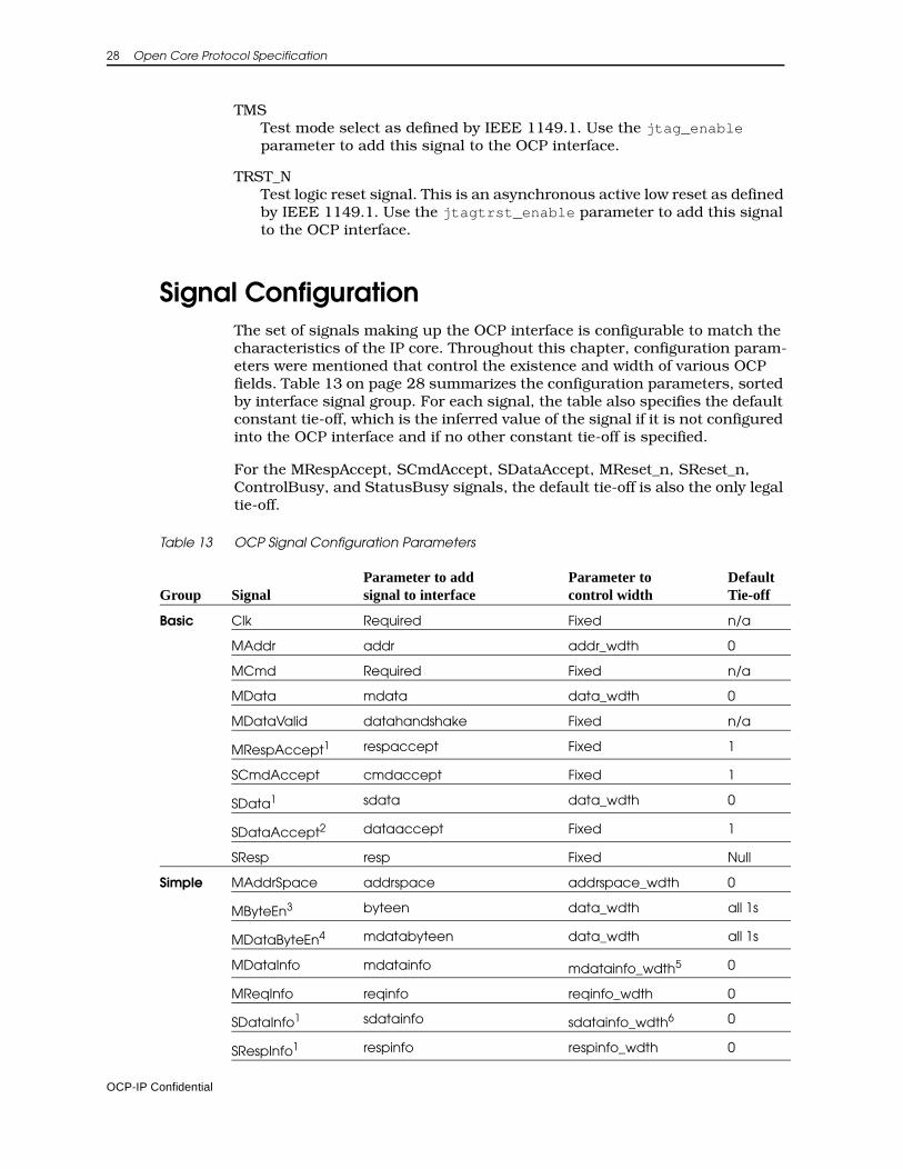
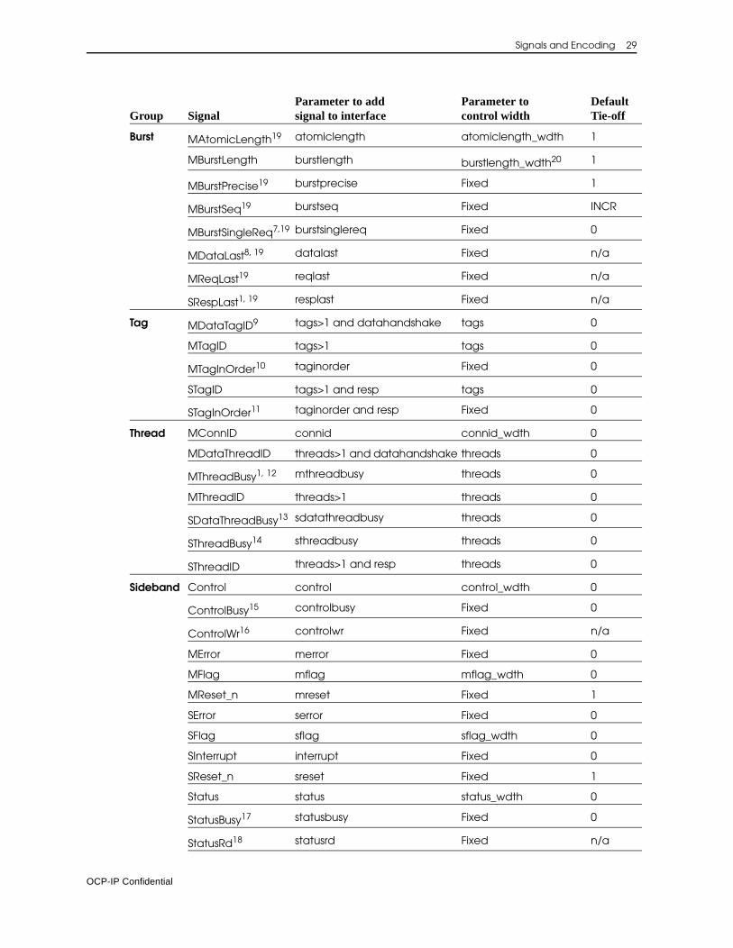
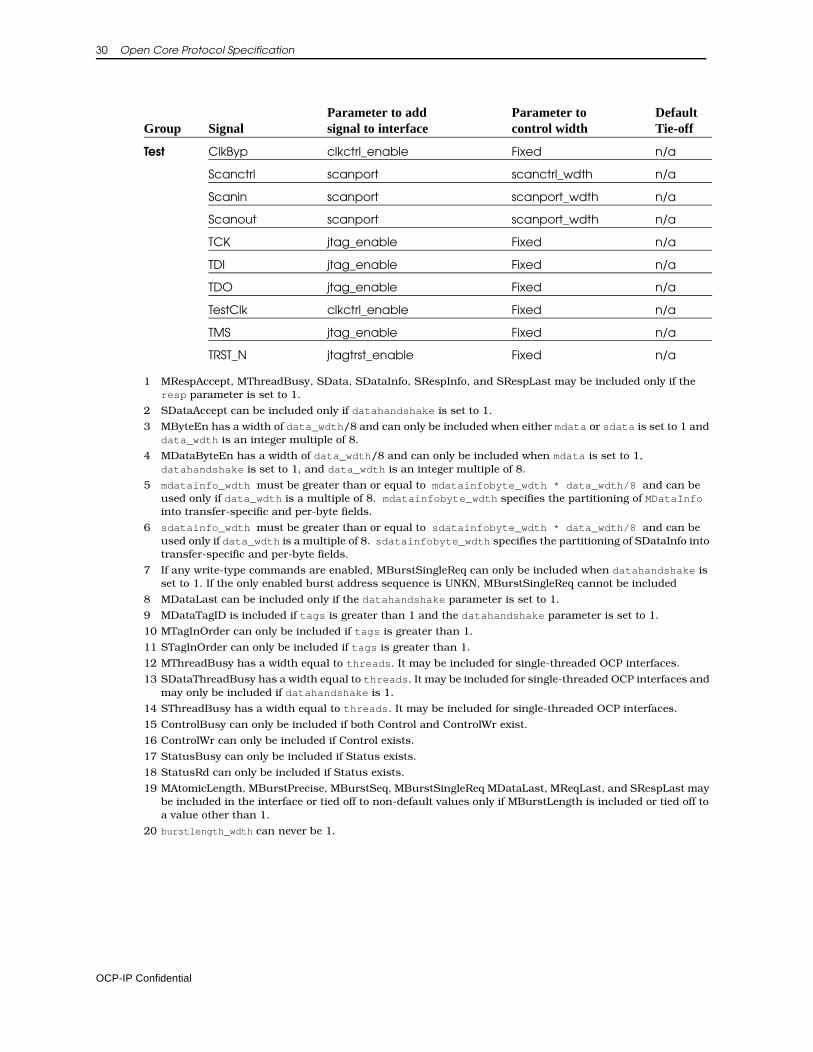
Signal ConfigurationThe set of signals making up the OCP interface is configurable to match the characteristics of the IP core. Throughout this chapter, configuration param-eters were mentioned that control the existence and width of various OCP fields. Table 13 on page 28 summarizes the configuration parameters, sorted by interface signal group. For each signal, the table also specifies the default constant tie-off, which is the inferred value of the signal if it is not configured into the OCP interface and if no other constant tie-off is specified.
For the MRespAccept, SCmdAccept, SDataAccept, MReset_n, SReset_n, ControlBusy, and StatusBusy signals, the default tie-off is also the only legal tie-off.
Table 13 OCP Signal Configuration Parameters
Group SignalParameter to add signal to interface
Parameter tocontrol width
Default Tie-off
Basic Clk Required Fixed n/a
MAddr addr addr_wdth 0
MCmd Required Fixed n/a
MData mdata data_wdth 0
MDataValid datahandshake Fixed n/a
MRespAccept1 respaccept Fixed 1
SCmdAccept cmdaccept Fixed 1
SData1 sdata data_wdth 0
SDataAccept2 dataaccept Fixed 1
SResp resp Fixed Null
Simple MAddrSpace addrspace addrspace_wdth 0
MByteEn3 byteen data_wdth all 1s
MDataByteEn4 mdatabyteen data_wdth all 1s
MDataInfo mdatainfo mdatainfo_wdth5 0
MReqInfo reqinfo reqinfo_wdth 0
SDataInfo1 sdatainfo sdatainfo_wdth6 0
SRespInfo1 respinfo respinfo_wdth 0
OCP-IP Confidential
Signals and Encoding 29
Burst MAtomicLength19 atomiclength atomiclength_wdth 1
MBurstLength burstlength burstlength_wdth20 1
MBurstPrecise19 burstprecise Fixed 1
MBurstSeq19 burstseq Fixed INCR
MBurstSingleReq7,19 burstsinglereq Fixed 0
MDataLast8, 19 datalast Fixed n/a
MReqLast19 reqlast Fixed n/a
SRespLast1, 19 resplast Fixed n/a
Tag MDataTagID9 tags>1 and datahandshake tags 0
MTagID tags>1 tags 0
MTagInOrder10 taginorder Fixed 0
STagID tags>1 and resp tags 0
STagInOrder11 taginorder and resp Fixed 0
Thread MConnID connid connid_wdth 0
MDataThreadID threads>1 and datahandshake threads 0
MThreadBusy1, 12 mthreadbusy threads 0
MThreadID threads>1 threads 0
SDataThreadBusy13 sdatathreadbusy threads 0
SThreadBusy14 sthreadbusy threads 0
SThreadID threads>1 and resp threads 0
Sideband Control control control_wdth 0
ControlBusy15 controlbusy Fixed 0
ControlWr16 controlwr Fixed n/a
MError merror Fixed 0
MFlag mflag mflag_wdth 0
MReset_n mreset Fixed 1
SError serror Fixed 0
SFlag sflag sflag_wdth 0
SInterrupt interrupt Fixed 0
SReset_n sreset Fixed 1
Status status status_wdth 0
StatusBusy17 statusbusy Fixed 0
StatusRd18 statusrd Fixed n/a
Group SignalParameter to add signal to interface
Parameter tocontrol width
Default Tie-off
OCP-IP Confidential
30 Open Core Protocol Specification
Test ClkByp clkctrl_enable Fixed n/a
Scanctrl scanport scanctrl_wdth n/a
Scanin scanport scanport_wdth n/a
Scanout scanport scanport_wdth n/a
TCK jtag_enable Fixed n/a
TDI jtag_enable Fixed n/a
TDO jtag_enable Fixed n/a
TestClk clkctrl_enable Fixed n/a
TMS jtag_enable Fixed n/a
TRST_N jtagtrst_enable Fixed n/a
1 MRespAccept, MThreadBusy, SData, SDataInfo, SRespInfo, and SRespLast may be included only if the resp parameter is set to 1.
2 SDataAccept can be included only if datahandshake is set to 1.
3 MByteEn has a width of data_wdth/8 and can only be included when either mdata or sdata is set to 1 and data_wdth is an integer multiple of 8.
4 MDataByteEn has a width of data_wdth/8 and can only be included when mdata is set to 1, datahandshake is set to 1, and data_wdth is an integer multiple of 8.
5 mdatainfo_wdth must be greater than or equal to mdatainfobyte_wdth * data_wdth/8 and can be used only if data_wdth is a multiple of 8. mdatainfobyte_wdth specifies the partitioning of MDataInfo into transfer-specific and per-byte fields.
6 sdatainfo_wdth must be greater than or equal to sdatainfobyte_wdth * data_wdth/8 and can be used only if data_wdth is a multiple of 8. sdatainfobyte_wdth specifies the partitioning of SDataInfo into transfer-specific and per-byte fields.
7 If any write-type commands are enabled, MBurstSingleReq can only be included when datahandshake is set to 1. If the only enabled burst address sequence is UNKN, MBurstSingleReq cannot be included
8 MDataLast can be included only if the datahandshake parameter is set to 1.
9 MDataTagID is included if tags is greater than 1 and the datahandshake parameter is set to 1.
10 MTagInOrder can only be included if tags is greater than 1.
11 STagInOrder can only be included if tags is greater than 1.
12 MThreadBusy has a width equal to threads. It may be included for single-threaded OCP interfaces.
13 SDataThreadBusy has a width equal to threads. It may be included for single-threaded OCP interfaces and may only be included if datahandshake is 1.
14 SThreadBusy has a width equal to threads. It may be included for single-threaded OCP interfaces.
15 ControlBusy can only be included if both Control and ControlWr exist.
16 ControlWr can only be included if Control exists.
17 StatusBusy can only be included if Status exists.
18 StatusRd can only be included if Status exists.
19 MAtomicLength, MBurstPrecise, MBurstSeq, MBurstSingleReq MDataLast, MReqLast, and SRespLast may be included in the interface or tied off to non-default values only if MBurstLength is included or tied off to a value other than 1.
20 burstlength_wdth can never be 1.
Group SignalParameter to add signal to interface
Parameter tocontrol width
Default Tie-off
OCP-IP Confidential
Signals and Encoding 31
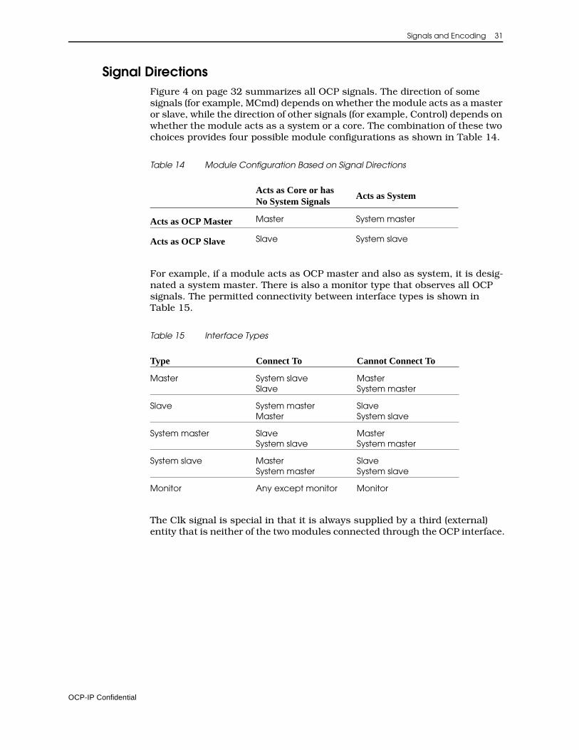
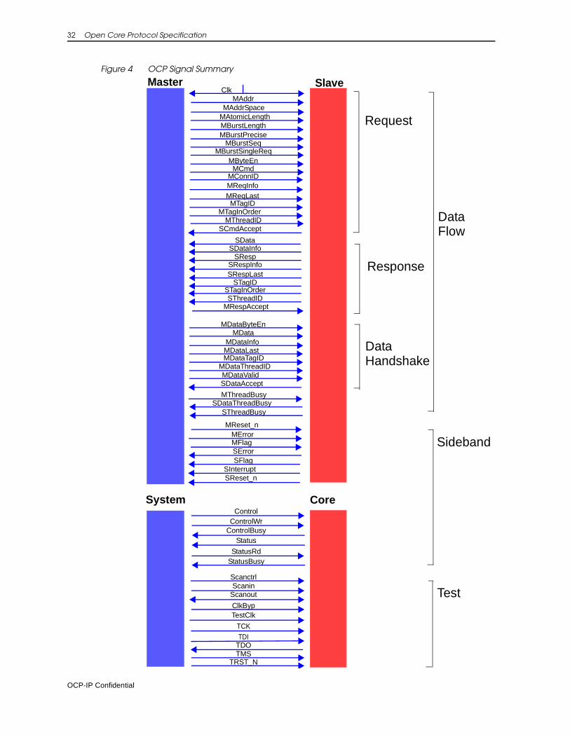
Signal DirectionsFigure 4 on page 32 summarizes all OCP signals. The direction of some signals (for example, MCmd) depends on whether the module acts as a master or slave, while the direction of other signals (for example, Control) depends on whether the module acts as a system or a core. The combination of these two choices provides four possible module configurations as shown in Table 14.
Table 14 Module Configuration Based on Signal Directions
For example, if a module acts as OCP master and also as system, it is desig-nated a system master. There is also a monitor type that observes all OCP signals. The permitted connectivity between interface types is shown in Table 15.
Table 15 Interface Types
The Clk signal is special in that it is always supplied by a third (external) entity that is neither of the two modules connected through the OCP interface.
Acts as Core or has No System Signals
Acts as System
Acts as OCP Master Master System master
Acts as OCP Slave Slave System slave
Type Connect To Cannot Connect To
Master System slave Slave
MasterSystem master
Slave System master Master
SlaveSystem slave
System master SlaveSystem slave
MasterSystem master
System slave MasterSystem master
SlaveSystem slave
Monitor Any except monitor Monitor
OCP-IP Confidential
32 Open Core Protocol Specification
Figure 4 OCP Signal Summary
ClkSlaveMaster
MCmd
MAddr
MBurstLength
SResp
SData
SCmdAcceptMThreadID
MConnID
MByteEn
SThreadIDMRespAccept
MReset_n
SInterrupt
SErrorSFlag
MFlag
ControlControlWr
ControlBusyStatus
StatusRdStatusBusy
ScanctrlScanin
Scanout
TestClkClkByp
TCKTDI
TDOTMS
TRST_N
MDataValid
MData
MDataThreadID
SDataAccept
System Core
MThreadBusy
SThreadBusy
MAddrSpace
MDataInfoMDataLast
SDataInfo
SRespInfoSRespLast
MAtomicLength
MBurstPreciseMBurstSeq
MBurstSingleReq
MReqInfoMReqLast
MError
Test
Sideband
Data
Response
Request
Data
Handshake
Flow
SReset_n
MDataByteEn
SDataThreadBusy
STagID
MDataTagID
MTagIDMTagInOrder
STagInOrder
OCP-IP Confidential
4 Protocol Semantics
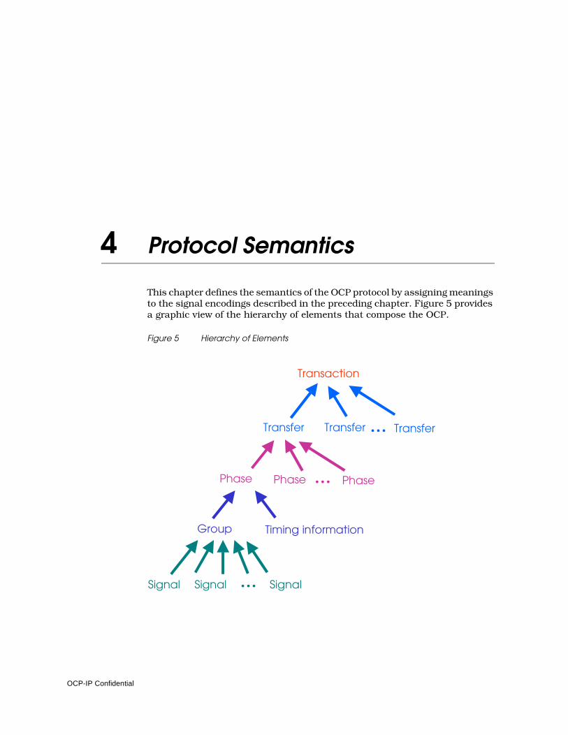
This chapter defines the semantics of the OCP protocol by assigning meanings to the signal encodings described in the preceding chapter. Figure 5 provides a graphic view of the hierarchy of elements that compose the OCP.
Figure 5 Hierarchy of Elements
Signal
Group
Phase Phase Phase...
Transfer
Transaction
Timing information
Transfer Transfer...
Signal Signal...
OCP-IP Confidential
34 Open Core Protocol Specification
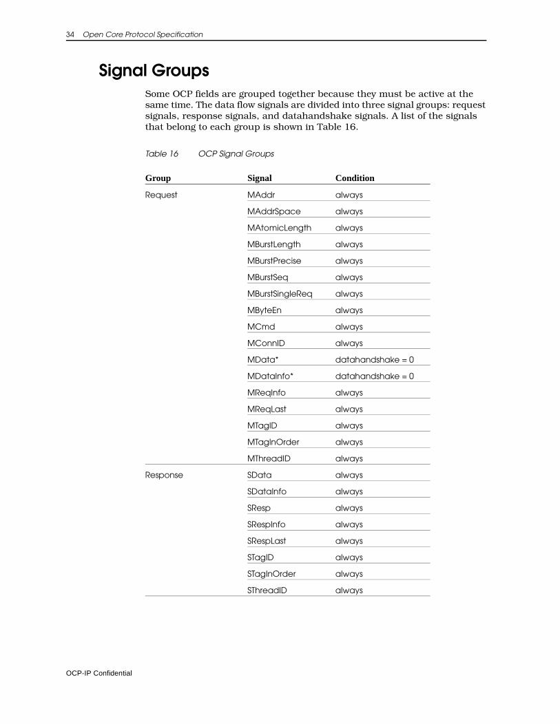
Signal GroupsSome OCP fields are grouped together because they must be active at the same time. The data flow signals are divided into three signal groups: request signals, response signals, and datahandshake signals. A list of the signals that belong to each group is shown in Table 16.
Table 16 OCP Signal Groups
Group Signal Condition
Request MAddr always
MAddrSpace always
MAtomicLength always
MBurstLength always
MBurstPrecise always
MBurstSeq always
MBurstSingleReq always
MByteEn always
MCmd always
MConnID always
MData* datahandshake = 0
MDataInfo* datahandshake = 0
MReqInfo always
MReqLast always
MTagID always
MTagInOrder always
MThreadID always
Response SData always
SDataInfo always
SResp always
SRespInfo always
SRespLast always
STagID always
STagInOrder always
SThreadID always
OCP-IP Confidential
Protocol Semantics 35
*MData and MDataInfo belong to the request group, unless the datahandshake configuration parameter is enabled. In that case they belong to the datahandshake group.
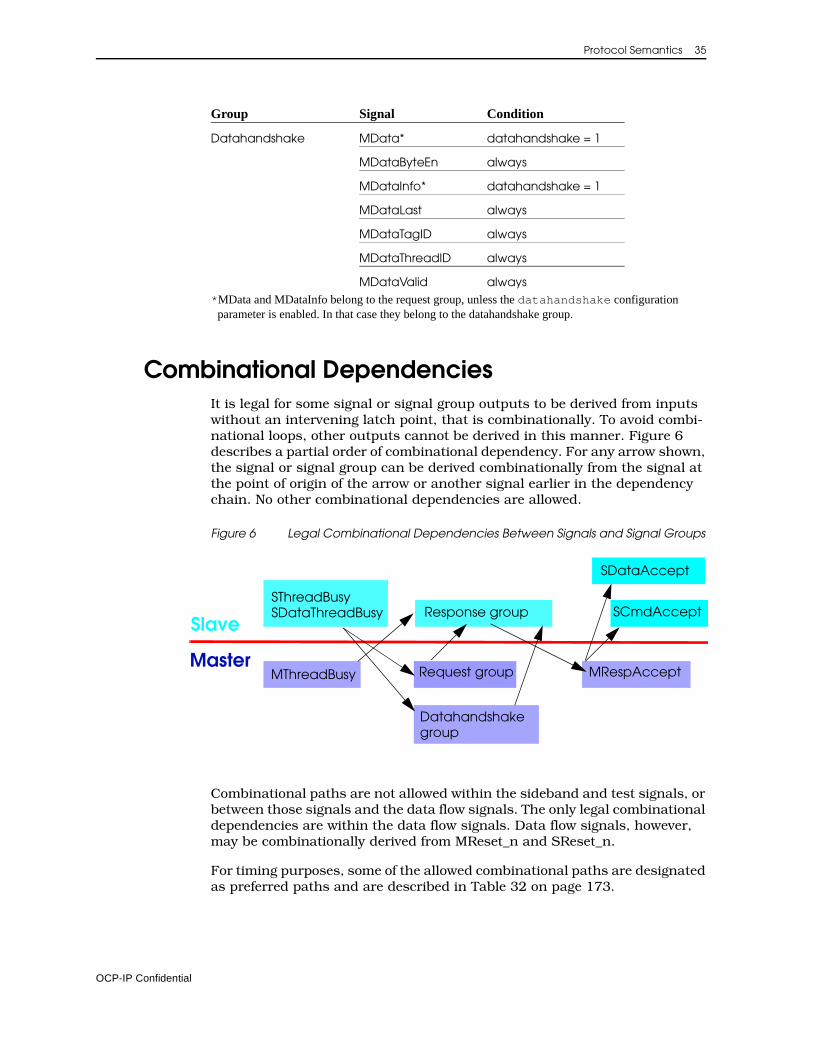
Combinational DependenciesIt is legal for some signal or signal group outputs to be derived from inputs without an intervening latch point, that is combinationally. To avoid combi-national loops, other outputs cannot be derived in this manner. Figure 6 describes a partial order of combinational dependency. For any arrow shown, the signal or signal group can be derived combinationally from the signal at the point of origin of the arrow or another signal earlier in the dependency chain. No other combinational dependencies are allowed.
Figure 6 Legal Combinational Dependencies Between Signals and Signal Groups
Combinational paths are not allowed within the sideband and test signals, or between those signals and the data flow signals. The only legal combinational dependencies are within the data flow signals. Data flow signals, however, may be combinationally derived from MReset_n and SReset_n.
For timing purposes, some of the allowed combinational paths are designated as preferred paths and are described in Table 32 on page 173.
Datahandshake MData* datahandshake = 1
MDataByteEn always
MDataInfo* datahandshake = 1
MDataLast always
MDataTagID always
MDataThreadID always
MDataValid always
Group Signal Condition
Request group
SCmdAcceptResponse group
MRespAccept
Datahandshake
SDataAccept
MThreadBusy
SThreadBusy
Master
Slave
group
SDataThreadBusy
OCP-IP Confidential
36 Open Core Protocol Specification
Signal Timing and Protocol PhasesThis section specifies when a signal can or must be valid.
Dataflow SignalsSignals in a signal group must all be valid at the same time.
• The request group is valid whenever a command other than Idle is presented on the MCmd field.
• The response group is valid whenever a response other than Null is presented on the SResp field.
• The datahandshake group is valid whenever a 1 is presented on the MDataValid field.
The accept signal associated with a signal group is valid only when that group is valid.
• The SCmdAccept signal is valid whenever a command other than Idle is presented on the MCmd field.
• The MRespAccept signal is valid whenever a response other than Null is presented on the SResp field.
• The SDataAccept signal is valid whenever a 1 is presented on the MDataValid field.
The signal groups map on a one-to-one basis to protocol phases. All signals in the group must be held steady from the beginning of a protocol phase until the end of that phase. Outside of a protocol phase, all signals in the corre-sponding group (except for the signal that defines the beginning of the phase) are “don’t care”.
In addition, the MData and MDataInfo fields are a "don't care" during read-type requests, and the SData and SDataInfo fields are a "don't care" for responses to write-type requests. Non-enabled data bytes in MData and bits in MDataInfo as well as non-enabled bytes in SData and bits in SDataInfo are a "don't care". The MDataByteEn field is a “don’t care” during read-type trans-fers. If MDataByteEn is present, the MByteEn field is a “don’t care” during write-type transfers. MTagID is a “don’t care” if MTagInOrder is asserted and MDataTagID is a “don’t care” for the corresponding datahandshake phase. Similarly, STagID is a “don’t care” if STagInOrder is asserted.
• A request phase begins whenever the request group becomes active. It ends when the SCmdAccept signal is sampled by Clk as 1 during a request phase.
• A response phase begins whenever the response group becomes active. It ends when the MRespAccept signal is sampled by Clk as 1 during a response phase.
OCP-IP Confidential
Protocol Semantics 37
If MRespAccept is not configured into the OCP interface (respaccept = 0) then MRespAccept is assumed to be on; that is the response phase is exactly one cycle long.
• A datahandshake phase begins whenever the datahandshake signal group becomes active. It ends when the SDataAccept signal is sampled by Clk as 1 during a datahandshake phase.
For all phases, it is legal to assert the corresponding accept signal in the cycle that the phase begins, allowing the phase to complete in a single cycle.
Phases in a TransferAn OCP transfer consists of several phases as shown in Table 17. Every transfer has a request phase. Read-type requests always have a response phase. For write-type requests, the OCP can be configured with or without responses or datahandshake. Without a response, a write-type request completes upon completion of the request phase (posted write model).
Table 17 Phases in a Transfer for MBurstSinqleReq set to 0
Single request / multiple data bursts, described in “Single Request / Multiple Data Bursts (Packets)” on page 47, have a single request phase and multiple data transfer phases as shown in Table 18.
Table 18 Phases in a Transfer for MBurstSinqleReq set to 1
MCmd Phases Condition
Read, ReadEx, ReadLinked
Request, response always
Write, Broadcast Request datahandshake = 0writeresp_enable = 0
Write, WriteNonPost, WriteConditional, Broadcast
Request, response datahandshake = 0writeresp_enable = 1
Write, Broadcast Request, datahandshake datahandshake = 1writeresp_enable = 0
Write, WriteNonPost, WriteConditional, Broadcast
Request, datahandshake, response datahandshake = 1writeresp_enable = 1
MCmd Phases Condition
Read Request, L* response
*L refers to the burst length
always
Write, Broadcast Request, L* datahandshake datahandshake = 1writeresp_enable = 0
Write, WriteNonPost, Broadcast
Request, L* datahandshake, response datahandshake = 1writeresp_enable = 1
OCP-IP Confidential
38 Open Core Protocol Specification
Phase Ordering Within a TransferThe OCP is causal: within each transfer a request phase must precede the associated datahandshake phase which in turn, must precede the associated response phase. The specific constraints are:
• A datahandshake phase cannot begin before the associated request phase begins, but can begin in the same Clk cycle.
• A datahandshake phase cannot end before the associated request phase ends, but can end in the same Clk cycle.
• A response phase cannot begin before the associated request phase begins, but can begin in the same Clk cycle.
• A response phase cannot end before the associated request phase ends, but can end in the same Clk cycle.
• If there is a datahandshake phase and a response phase, the response phase cannot begin before the associated datahandshake phase (or last datahandshake phase for single request/multiple data bursts) begins, but can begin in the same Clk cycle.
• If there is a datahandshake phase and a response phase, the response phase cannot end before the associated datahandshake phase (or last datahandshake phase for single request/multiple data bursts) ends, but can end in the same Clk cycle.
Phase Ordering Between TransfersIf tags are not in use, the ordering of transfers is determined by the ordering of their request phases. Also, the following rules apply.
• Since two phases of the same type belonging to different transfers both use the same signal wires, the phase of a subsequent transfer cannot begin before the phase of the previous transfer has ended. If the first phase ends in cycle x, the second phase can begin in cycle x + 1.
• The ordering of datahandshake phases must follow the order set by the request phases including multiple datahandshake phases for single request / multiple data bursts.
• The ordering of response phases must follow the order set by the request phases including multiple response phases for single request / multiple data bursts.
• For single request / multiple data bursts, a request or response phase is shared between multiple transfers. Each individual transfer must obey the ordering rules described in “Phase Ordering Within a Transfer” on page 38, even when a phase is shared with another transfer.
• Where no phase ordering is specified, by the previous rules, the effect of two transfers that are addressing the same location (as specified by MAddr, MAddrSpace, and MByteEn) must be the same as if the two transfers were executed in the same order but without any phase overlap. This ensures that read/write hazards yield predictable results.
OCP-IP Confidential
Protocol Semantics 39
For example, on an OCP interface with datahandshake enabled, a read following a write to the same location cannot start its response phase until the write has started its datahandshake phase, otherwise the latest write data cannot be returned for the read.
If tags are in use, the preceding rules are partially relaxed. Refer to “Ordering Restrictions” on page 48 for a more detailed explanation.
Ungrouped SignalsSignals not covered in the description of signal groups and phases are MThreadBusy, SDataThreadBusy, and SThreadBusy. Without further protocol restriction, the cycle timing of the transition of each bit that makes up each of these three fields is not specified relative to the other dataflow signals. This means that there is no specific time for an OCP master or slave to drive these signals, nor a specific time for the signals to have the desired flow-control effect. Without further restriction, MThreadBusy, SDataThread-Busy, and SThreadBusy can only be treated as a hint. It is possible to force stricter semantics using the protocol configuration parameters mthreadbusy_exact, sdatathreadbusy_exact, and sthreadbusy_exact. These parameters can be set to 1 only if the corresponding signal has been enabled. The effect of these parameters is as follows:
• If mthreadbusy_exact is enabled for a master and the master is unable to accept a response on a thread in a given cycle, it must set the MThreadBusy bit for that thread to 1 in that cycle. If a response is presented on a thread for which MThreadBusy is not set to 1 in the current cycle, it must be accepted by the master in that cycle.
If mthreadbusy_exact is enabled for a slave, the slave must take the MThreadBusy signal into account for the thread selection of the current cycle, that is, it must not present a response on a thread for which the corresponding MThreadBusy bit is set to 1 in the cycle.
• If sdatathreadbusy_exact is enabled for a slave that is unable to accept a datahandshake phase on a thread in a given cycle, it must set the SDataThreadBusy bit for that thread to 1 in that cycle. If a datahandshake phase is presented on a thread for which SDataThreadBusy is not set to 1 in the current cycle, it must be accepted by the slave in that cycle.
If sdatathreadbusy_exact is enabled for a master, the master must take the SDataThreadBusy signal into account for the thread selection of the current cycle, that is, it must not present a datahandshake phase on a thread for which the corresponding SDataThreadBusy bit is set to 1 in this cycle.
• If sthreadbusy_exact is enabled for a slave that is unable to accept a command on a thread in a given cycle, it must set the SThreadBusy bit for that thread to 1 in that cycle. If a command is presented on a thread for which SThreadBusy is not set to 1 in the current cycle, it must be accepted by the slave in that cycle.
OCP-IP Confidential
40 Open Core Protocol Specification
If sthreadbusy_exact is enabled for a master, the master must take the SThreadBusy signal into account for the thread selection of the current cycle, that is, it must not present a command on a thread for which the corresponding SThreadBusy bit is set to 1 in this cycle.
A multi-threaded OCP interface is guaranteed to be non-blocking only if all of the following conditions are satisfied:
1. cmdaccept is set to 0 and SCmdAccept is tied off to a value of 1.
2. If sthreadbusy is set to 1, sthreadbusy_exact is set to 1 for both master and slave.
3. If datahandshake is set to 1, dataaccept is set to 0 and SDataAccept is tied off to a value of 1.
4. If datahandshake is set to 1 and sdatathreadbusy is set to 1, sdatathreadbusy_exact is set to 1 for both master and slave.
5. respaccept is set to 0 and MRespAccept is tied off to a value of 1.
6. If mthreadbusy is set to 1, mthreadbusy_exact is set to 1 for both master and slave.
Sideband and Test Signals
ResetThe OCP interface provides an interface reset signal for each master and slave. At least one of these signals must be present. If both signals are present, the composite reset state of the interface is derived as the logical AND of the two signals (that is, the interface is in reset as long as one of the two resets is asserted).
Once one or both reset signals are sampled asserted by the rising edge of Clk, all incomplete transactions, transfers and phases are terminated and both master and slave must transition to a state where there are no pending OCP requests or responses. MReset_n and SReset_n must be asserted for at least 16 cycles of Clk to ensure that the master and slave reach a consistent internal state. When one or both of the reset signals are asserted in a given cycle, all other OCP signals must be ignored in that cycle. The master and slave must each be able to reach their reset state regardless of the values presented on the OCP signals. If the master or slave require more than 16 cycles of reset assertion, the requirement must be documented in the IP core specifications.
At the clock edge that all reset signals present are sampled deasserted, all OCP interface signals must be valid. In particular, it is legal for the master to begin its first request phase in the same clock cycle that reset is deasserted.
Interrupt, Error, and Core FlagsThere is no specific timing associated with SInterrupt, SError, MFlag, MError, and SFlag. The timing of these signals is core-specific.
OCP-IP Confidential
Protocol Semantics 41
Status and ControlThe following rules assure that control and status information can be exchanged across the OCP without any combinational paths from inputs to outputs and at the pace of a slow core.
• Control must be held steady for a full cycle after the cycle in which it has transitioned, which means it cannot transition more frequently than every other cycle. If ControlBusy was sampled active at the end of the previous cycle, Control must not transition in the current cycle. In addition, Control must be held steady for the first two cycles after reset is deasserted.
• If Control transitions in a cycle, ControlWr (if present) must be driven active for that cycle. ControlWr following the rules for Control, cannot be asserted in two consecutive cycles.
• ControlBusy allows a core to force the system to hold Control steady. ControlBusy may only start to be asserted immediately after reset, or in the cycle after ControlWr is asserted, but can be left asserted for any number of cycles.
• While StatusBusy is active, Status is a “don’t care”. StatusBusy enables a core to prevent the system from reading the current status information. While StatusBusy is active the core may not read Status. StatusBusy can be asserted at any time and be left asserted for any number of cycles.
• StatusRd is active for a single cycle every time the status register is read by the system. If StatusRd was asserted in the previous cycle, it must not be asserted in the current cycle, so it cannot transition more frequently than every other cycle.
Test SignalsScanin and Scanout are “don’t care” while Scanctrl is inactive (but the encoding of inactive for Scanctrl is core-specific).
TestClk is “don’t care” while ClkByp is 0.
The timing of TRST_N, TCK, TMS, TDI, and TDO is specified in the IEEE 1149 standard.
Transfer EffectsA successful transfer is one that completes without error. For write-type requests without responses, there can be no in-band error indication. For all other requests, a non-ERR response (that is, a DVA or FAIL response) indi-cates a successful transfer. The FAIL response is legal only for WriteConditional commands. This section defines the effect that a successful transfer has on a slave. The request acts on the addressed location, where the term address refers to the combination of MAddr, MAddrSpace, and MByteEnable (or MDataByteEn, if applicable). Two addresses are said to match if they are identical in all components. Two addresses are said to
OCP-IP Confidential
42 Open Core Protocol Specification
conflict, if the mutual exclusion (lock or monitor) logic is built to alias the two addresses into the same mutual exclusion unit. The transfer effects of each command are:
IdleNone.
ReadReturns the latest value of the addressed location on the SData field.
ReadExReturns the latest value of the addressed location on the SData field. Sets a lock for the initiating thread on that location. The next request on the thread that issued a ReadEx must be a Write or WriteNonPost to the matching address. Requests from other threads to a conflicting address that is locked are blocked from proceeding until the lock is released. If the ReadEx request returns an ERR response, it is slave-specific whether the lock is actually set or not.
ReadLinkedReturns the latest value of the addressed location on the SData field. Sets a reservation in a monitor for the corresponding thread on at least that location. Requests of any type from any thread to a conflicting address that is reserved are not blocked from proceeding, but may clear the reservation.
Write/WriteNonPostPlaces the value on the MData field in the addressed location. Unlocks access to the matched address if locked by a ReadEx. Clears the reservations on any conflicting addresses set by other threads.
WriteConditionalIf a reservation is set for the matching address and for the corresponding thread, the write is performed as it would be for a Write or WriteNonPost. Simultaneously, the reservation is cleared for all threads on any conflicting address. If no reservation is set for the corresponding thread, the write is not performed, a FAIL response is returned, and no reservations are cleared.
BroadcastPlaces the value on the MData field in the addressed location that may map to more than one slave in a system-dependent way. Broadcast clears the reservations on any conflicting addresses set by other threads.
If a transfer is unsuccessful, the effect of the transfer is unspecified. It is up to higher-level protocols to determine what happened and handle any clean-up.
The synchronization commands ReadEx / Write, ReadEx / WriteNonPost, and ReadLinked / WriteConditional have special restrictions with regard to data width conversion and partial words. In systems where these commands are sent through a bridge or interconnect that performs wide-to-narrow data width conversion between two OCP interfaces, the initiator must issue only commands within the subset of partial words that can be expressed as a single word of the narrow OCP interface. For maximum portability, single-byte synchronization operations are recommended.
OCP-IP Confidential
Protocol Semantics 43
Partial Word TransfersAn OCP interface may be configured to include partial word transfers by using either the MByteEn field, or the MDataByteEn field, or both.
• If neither field is present, then only whole word transfers are possible.
• If only MByteEn is present, then the partial word is specified by this field for both read type transfers and write type transfers as part of the request phase.
• If only MDataByteEn is present, then the partial word is specified by this field for write type transfers as part of the datahandshake phase, and partial word reads are not supported.
• If both MByteEn and MDataByteEn are present, then MByteEn specifies partial words for read transfers as part of the request phase, and MDataByteEn specifies partial words for write transfers as part of the datahandshake phase.
It is legal to use a request with all byte enables deasserted. Such requests must follow all the protocol rules, except that they are treated as no-ops by the slave: the response phase signals SData and SDataInfo are "don't care" for read-type commands, and nothing is written for write-type commands.
Posting SemanticsThe OCP includes a basic Write command. Typically, a system designer decides what write completion model to assign to a core’s write commands. If the OCP is configured to not respond to write-type commands (writeresp_enable set to 0), a posted write completion model is assumed. It is also possible to achieve a non-posted model by not accepting the command until the write completes, but this de-pipelines the OCP interface and is not recommended.
If the OCP is configured to respond to write-type commands (writeresp_enable set to 1), either a posted or a non-posted write comple-tion model can be used. For cores that need to determine on a per-transfer basis whether a write is to be treated as posted or non-posted, the OCP provides the WriteNonPost command.
EndiannessAn OCP interface by itself is inherently endian-neutral. Data widths must match between master and slave, addressing is on an OCP word granularity, and byte enables are tied to byte lanes (data bits) without tying the byte lanes to specific byte addresses.
The issue of endianness arises in the context of multiple OCP interfaces, where the data widths of the initiator of a request and the final target of that request do not match. Examples are a bridge or a more general interconnect used to connect OCP-based cores.
OCP-IP Confidential
44 Open Core Protocol Specification
When the OCP interfaces differ in data width, the interconnect must associate an endianness with each transfer. It does so by associating byte lanes and byte enables of the wider OCP with least-significant word address bits of the narrower OCP. Packing rules, described in “Packing” on page 46 must also be obeyed for bursts.
OCP interfaces can be designated as little, big, both, or neutral with respect to endianness. This is specified using the protocol parameter endian described in “Endianness” on page 53. A core that is designated as both typi-cally represents a device that can change endianness based upon either an internal configuration register or an external input. A core that is designated as neutral typically represents a device that has no inherent endianness. This indicates that either the association of an endianness is arbitrary (as with a memory, which traditionally has no inherent endianness) or that the device only works with full-word quantities (when byteen and mdatabyteen are set to 0).
When all cores have the same endianness, an interconnect should match the endianness of the attached cores. The details of any conversion between cores of different endianness is implementation-specific.
Burst DefinitionA burst is a set of transfers that are linked together into a transaction having a defined address sequence and number of transfers. There are three general categories of bursts:
Imprecise burstsRequest information is given for each transfer. Length information may change during the burst.
Precise burstsRequest information is given for each transfer, but length information is constant throughout the burst.
Single request / multiple data bursts (also known as packets)Also a precise burst, but request information is given only once for the entire burst.
To express bursts on the OCP interface, at least the address sequence and length of the burst must be communicated, either directly using the MBurstSeq and MBurstLength signals, or indirectly through an explicit constant tie-off as described in “Signal Mismatch Tie-off Rules” on page 57.
A single (non-burst) request on an OCP interface with burst support is encoded as a request with any legal burst address sequence and a burst length of 1.
The ReadEx, ReadLinked, and WriteConditional commands can not be used as part of a burst. The unlocking Write or WriteNonPost command associated with a ReadEx command also can not be used as part of a burst.
OCP-IP Confidential
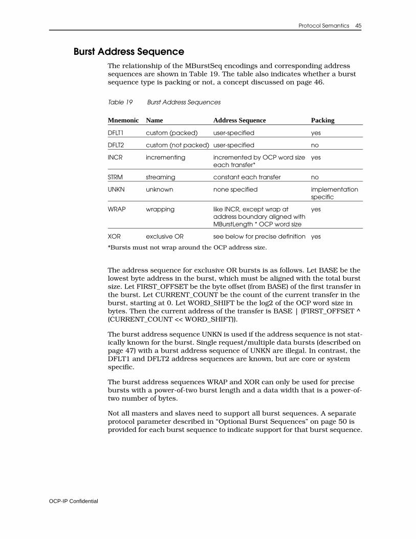
Protocol Semantics 45
Burst Address SequenceThe relationship of the MBurstSeq encodings and corresponding address sequences are shown in Table 19. The table also indicates whether a burst sequence type is packing or not, a concept discussed on page 46.
Table 19 Burst Address Sequences
*Bursts must not wrap around the OCP address size.
The address sequence for exclusive OR bursts is as follows. Let BASE be the lowest byte address in the burst, which must be aligned with the total burst size. Let FIRST_OFFSET be the byte offset (from BASE) of the first transfer in the burst. Let CURRENT_COUNT be the count of the current transfer in the burst, starting at 0. Let WORD_SHIFT be the log2 of the OCP word size in bytes. Then the current address of the transfer is BASE | (FIRST_OFFSET ^ (CURRENT_COUNT << WORD_SHIFT)).
The burst address sequence UNKN is used if the address sequence is not stat-ically known for the burst. Single request/multiple data bursts (described on page 47) with a burst address sequence of UNKN are illegal. In contrast, the DFLT1 and DFLT2 address sequences are known, but are core or system specific.
The burst address sequences WRAP and XOR can only be used for precise bursts with a power-of-two burst length and a data width that is a power-of-two number of bytes.
Not all masters and slaves need to support all burst sequences. A separate protocol parameter described in “Optional Burst Sequences” on page 50 is provided for each burst sequence to indicate support for that burst sequence.
Mnemonic Name Address Sequence Packing
DFLT1 custom (packed) user-specified yes
DFLT2 custom (not packed) user-specified no
INCR incrementing incremented by OCP word size each transfer*
yes
STRM streaming constant each transfer no
UNKN unknown none specified implementation specific
WRAP wrapping like INCR, except wrap at address boundary aligned withMBurstLength * OCP word size
yes
XOR exclusive OR see below for precise definition yes
OCP-IP Confidential
46 Open Core Protocol Specification
Byte Enable RestrictionsBurst address sequences STRM and DFLT2 must have at least one byte enable asserted for each transfer in the burst. Bursts with the STRM address sequence must have the same byte enable pattern for each transfer in the burst.
PackingPacking allows the system to make use of the burst attributes to improve the overall data transfer efficiency in the face of multiple OCP interfaces of different data widths. For example, if a bridge is translating a narrow OCP to a wide OCP, it can aggregate (or pack) the incoming narrow transfers into a smaller number of outgoing wide transfers. Burst address sequences are clas-sified as either packing, or not packing.
For burst address sequences that are packing, the conversion between different OCP data widths is achieved through aggregation or splitting. Narrow OCP words are collected together to form a wide OCP word. A wide OCP word is split into several narrow OCP words. The byte-specific portion of MDataInfo and SDataInfo is aggregated or split with the data. The transfer-specific portion of MDataInfo and SDataInfo is unaffected. The packing and unpacking order depends on endianness as described on page 43.
For burst address sequences that are not packing, conversion between different OCP data widths is achieved using padding and stripping. A narrow OCP word is padded to form a wide OCP word with only the relevant byte enables turned on. A wide OCP word is stripped to form a narrow OCP word. The byte-specific portion of MDataInfo and SDataInfo is zero-padded or stripped with the data. The transfer-specific portion of MDataInfo and SDataInfo is unaffected. Width conversion can be performed reliably only if the wide OCP interface has byte enables associated with it. For wide to narrow conversion the byte enables are restricted to a subset that can be expressed within a single word of the narrow OCP interface.
Since the address sequence of DFLT1 is user-specified, the behavior of DFLT1 bursts through data width conversion is implementation-specific.
Burst Length, Precise and Imprecise BurstsThe MBurstLength field indicates the number of transfers in the burst.
Precise bursts (MBurstPrecise set to 1) MBurstLength must be held constant throughout the burst, so the exact burst length can be obtained from the first transfer. A precise burst is completed by the transfer of the correct number of OCP words. Precise bursts are recommended over imprecise bursts because they allow for increased hardware optimization.
Imprecise bursts (MBurstPrecise set to 0) MBurstLength can change throughout the burst, and indicates the current best guess of the number of transfers left in the burst (including the current one). An imprecise burst is completed by an MBurstLength of 1.
OCP-IP Confidential
Protocol Semantics 47
Constant Fields in BurstsMCmd, MAddrSpace, MConnID, MBurstPrecise, MBurstSingleReq, MBurstSeq, MAtomicLength, and MReqInfo must all be held steady by the master for every transfer in a burst, regardless of whether the burst is precise or imprecise. If possible, slaves should hold SRespInfo steady for every transfer in a burst.
AtomicityWhen interleaving requests from different initiators on the way to or at the target, the master uses MAtomicLength to indicate the number of OCP words within a burst that must be kept together as an atomic quantity. If MAtomi-cLength is greater than the actual length of the burst, the atomicity requirement ends with the end of the burst. Specifying atomicity require-ments explicitly is especially useful when multiple OCP interfaces are involved that have different data widths.
For master cores, it is best to make the atomic size as small as required and, if possible, to keep the groups of atomic words address-aligned with the group size.
Single Request / Multiple Data Bursts (Packets)MBurstSingleReq specifies whether a burst can be communicated using a single request / multiple data protocol. When MBurstSingleReq is 0, each request has a single data word associated with it. When MBurstSingleReq is 1, each request may have multiple data words associated with it, according to the value of MBurstLength. MBurstSingleReq may be set to 1 only if MBurst-Precise is set to 1. In addition, if any write-type commands are enabled, datahandshake must be set to 1.
When MBurstSingleReq is set to 1, write type transfers have MBurstLength phases and a single response phase (if writeresp_enable=1) per request; while read-type transfers have MBurstLength response phases per request as shown in Table 18 on page 37.
For write type transfers when MBurstSingleReq is set to 1 and the MDataBy-teEn field is present, that field in each data transfer phase specifies the partial word pattern for the phase. When MBurstSingleReq is set to 1 and the MDataByteEn field is not present, the MByteEn pattern of the request phase applies to all data transfer phases.
For read type transfers when MBurstSingleReq is set to 1, the MByteEn field specifies the byte enable pattern that is applied to all data transfers in the burst.
MReqLast, MDataLast, SRespLastOptional signals MReqLast, MDataLast, and SRespLast provide redundant information that indicates the last request, datahandshake, and response phase in a burst, respectively. These signals are provided as a convenience to
OCP-IP Confidential
48 Open Core Protocol Specification
the recipient of the signal. To avoid separate counting mechanisms to track bursts, cores that have the information available internally are encouraged to provide it at the OCP interface.
MReqLast is 0 for all request phases in a burst except the last one. MReqLast is 1 for the last request phase in a burst, for single request / multiple data bursts, and for single requests.
MDataLast is 0 for all datahandshake phases in a burst except the last one. MDataLast is 1 for the last datahandshake phase in a burst and for the only datahandshake phase of a single request.
SRespLast is 0 for all response phases in a burst except the last one. SRes-pLast is 1 for the last response phase in a burst, for the response to a write-type single request / multiple data burst, and for the response to a single request.
TagsTags allow out-of-order return of responses and out-of-order commit of write data.
A master drives a tag on MTagID during the request phase. The value of the tag is determined by the master and may or may not convey meaning beyond ordering to the slave. For write transactions with data handshake enabled, the master repeats the same tag on MDataTagID during the datahandshake phase. For read transactions and writes with responses the slave returns the tag of the corresponding request on STagID while supplying the response. The same tag must be used for an entire transaction.
Ordering RestrictionsThe sequence of requests by the master determines the initial ordering of tagged transactions. For tagged write transactions with datahandshake enabled, the datahandshake phase must observe the same order as the request phase. The master cannot interleave requests or datahandshake phases with different tags within a transaction.
Tag values can be re-used for multiple outstanding transactions. Slaves are responsible for committing write data and sending responses for multiple transactions that have the same tag, in order.
Responses with different tags can be returned in any order for all commands that have responses. Responses with the same tag must remain in order with respect to one another. Responses that are part of the same transaction must stay together, up to the tag_interleave_size (see “Burst Interleaving with Tags” on page 53). Beyond the tag_interleave_size, responses with different tags can be interleaved. This allows for blocks of responses corre-sponding to tag_interleave_size from one burst to be interleaved with blocks of responses from other bursts.
OCP-IP Confidential
Protocol Semantics 49
Responses to requests that target overlapping addresses (as determined by MAddrSpace, MAddr, and MByteEn) are never re-ordered with respect to one another. Similarly, responses to requests that are issued with MTagInOrder asserted are also never reordered with respect to one another. The value returned on STagInOrder with the slave’s response must match the value provided on MTagInOrder with the master’s request.
When tags are in use and writes are not posted, write response order indicates the order that writes are committed by the slave. When writes are posted, the response to a tagged read can only be guaranteed to be ordered with respect to writes to overlapping addresses. This is different than non-tagged versions of OCP interfaces, where read responses are sometimes used to ensure completion of all earlier posted writes.
Threads and ConnectionsUsing multiple threads, it is possible to support concurrent activity, and out-of-order completion of transfers. All transfers within a given thread must either remain strictly ordered or follow the tag ordering rules, but there are no ordering rules for transfers that are in different threads. Mapping of indi-vidual requests and responses to threads is handled through the MThreadID and SThreadID fields respectively. If datahandshake has been enabled when multiple threads are present, there must also be an MDataThreadID field to annotate the datahandshake phase. If datahandshake is set to 1 and sdatathreadbusy is set to 0, the order of datahandshake phases must follow the order of request phases across all threads. If sdatathreadbusy is set to 1, the request order and datahandshake order are independent across threads.
The use of thread IDs allows two entities that are communicating over an OCP interface to assign transfers to particular threads. If one of the communi-cating entities is itself a bridge to another OCP interface, the information about which transfers are part of which thread must be maintained by the bridge, but the actual assignment of thread IDs is done on a per-OCP-inter-face basis. There is no way for a slave on the far side of a bridge to extract the original thread ID unless the slave design comprehends the characteristics of the bridge.
Use connections whenever source thread information about a request must be sent end-to-end from master to slave. Any bridges in the path between the end-to-end partners preserve the connection ID, even as thread IDs are re-assigned on each OCP interface in the path. The MConnID field transfers the connection ID during the request phase. Since this establishes the mapping onto a thread ID, the other phases do not require a connection ID but are unambiguous with only a thread ID.
The SThreadBusy, SDataThreadbusy, and MThreadBusy signals are used to indicate that a particular thread is busy. The protocol parameters sthreadbusy_exact, sdatathreadbusy_exact, and mthreadbusy_exact can be used to force precise semantics for these signals and assure that a multi-threaded OCP interface never blocks. For more information, see “Ungrouped Signals” on page 39.
OCP-IP Confidential
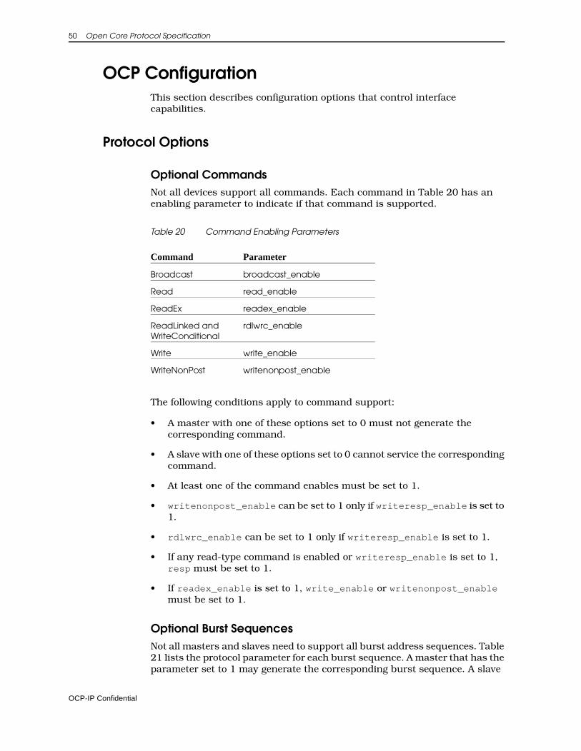
50 Open Core Protocol Specification
OCP ConfigurationThis section describes configuration options that control interface capabilities.
Protocol Options
Optional CommandsNot all devices support all commands. Each command in Table 20 has an enabling parameter to indicate if that command is supported.
Table 20 Command Enabling Parameters
The following conditions apply to command support:
• A master with one of these options set to 0 must not generate the corresponding command.
• A slave with one of these options set to 0 cannot service the corresponding command.
• At least one of the command enables must be set to 1.
• writenonpost_enable can be set to 1 only if writeresp_enable is set to 1.
• rdlwrc_enable can be set to 1 only if writeresp_enable is set to 1.
• If any read-type command is enabled or writeresp_enable is set to 1, resp must be set to 1.
• If readex_enable is set to 1, write_enable or writenonpost_enable must be set to 1.
Optional Burst SequencesNot all masters and slaves need to support all burst address sequences. Table 21 lists the protocol parameter for each burst sequence. A master that has the parameter set to 1 may generate the corresponding burst sequence. A slave
Command Parameter
Broadcast broadcast_enable
Read read_enable
ReadEx readex_enable
ReadLinked and WriteConditional
rdlwrc_enable
Write write_enable
WriteNonPost writenonpost_enable
OCP-IP Confidential
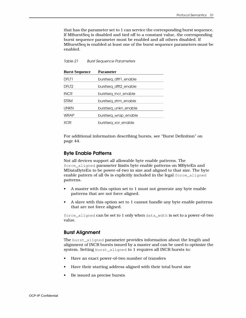
Protocol Semantics 51
that has the parameter set to 1 can service the corresponding burst sequence. If MBurstSeq is disabled and tied off to a constant value, the corresponding burst sequence parameter must be enabled and all others disabled. If MBurstSeq is enabled at least one of the burst sequence parameters must be enabled.
Table 21 Burst Sequence Parameters
For additional information describing bursts, see “Burst Definition” on page 44.
Byte Enable PatternsNot all devices support all allowable byte enable patterns. The force_aligned parameter limits byte enable patterns on MByteEn and MDataByteEn to be power-of-two in size and aligned to that size. The byte enable pattern of all 0s is explicitly included in the legal force_aligned patterns.
• A master with this option set to 1 must not generate any byte enable patterns that are not force aligned.
• A slave with this option set to 1 cannot handle any byte enable patterns that are not force aligned.
force_aligned can be set to 1 only when data_wdth is set to a power-of-two value.
Burst AlignmentThe burst_aligned parameter provides information about the length and alignment of INCR bursts issued by a master and can be used to optimize the system. Setting burst_aligned to 1 requires all INCR bursts to:
• Have an exact power-of-two number of transfers
• Have their starting address aligned with their total burst size
• Be issued as precise bursts
Burst Sequence Parameter
DFLT1 burstseq_dflt1_enable
DFLT2 burstseq_dflt2_enable
INCR burstseq_incr_enable
STRM burstseq_strm_enable
UNKN burstseq_unkn_enable
WRAP burstseq_wrap_enable
XOR burstseq_xor_enable
OCP-IP Confidential
52 Open Core Protocol Specification
Flow Control OptionsTo permit the SThreadBusy and MThreadBusy signals to guarantee a non-blocking, multi-threaded OCP interface, the sthreadbusy_exact and mthreadbusy_exact parameters require strict semantics. See “Ungrouped Signals” on page 39 for a precise definition of these parameters. Table 22 describes the legal combinations of phase handshake signals.
Table 22 Request Phase Without Datahandshake
When datahandshake is set to 1, the preceding rules for cmdaccept, sthreadbusy, and sthreadbusy_exact also apply to dataaccept, sdatath-readbusy, and sdatathreadbusy_exact. In addition, blocking and non-blocking flow control must not be mixed for the request and datahandshake phase. A phase using no flow control can be mixed with phases using either blocking or non-blocking type flow control. The legal combinations are shown in Table 23.
Table 23 Request Phase with Datahandshake
1 Only legal if reqdata_together is set to 0.
2 Only legal if reqdata_together is set to 0. In addition the master must not assert the datah-andshake phase until after the associated request phase has been accepted.
cmdaccept sthreadbusy sthreadbusy_exact Explanation
0 0 0 Legal: no flow control
0 0 1 Illegal: sthreadbusy_exact must be 0 when sthreadbusy is 0
0 1 0 Illegal: no real flow control
0 1 1 Legal: non-blocking flow control
1 0 0 Legal: blocking flow control
1 0 1 Illegal: sthreadbusy_exact must be 0 when sthreadbusy is 0
1 1 0 Legal: blocking flow control with hints
1 1 1 Illegal: since SCmdAccept is present flow control cannot be exact
Datahandshake Phase Flow Control
None Blocking Non-blocking
Request PhaseFlow Control
None Legal Legal1 Legal
Blocking Legal2 Legal Illegal
Non-blocking Legal Illegal Legal
OCP-IP Confidential

Protocol Semantics 53
The preceding rules for the request phase using cmdaccept, sthreadbusy, and sthreadbusy_exact also apply to the response phase for respaccept, mthreadbusy, and mthreadbusy_exact.
EndiannessThe endian parameter specifies the endianness of a core. The behavior of each endianness choice is summarized in Table 24.
Table 24 Endianness
As far as OCP is concerned, little endian means that lower addresses are asso-ciated with lower numbered data bits (byte lanes), while big endian means that higher addresses are associated with lower numbered data bits (byte lanes). This becomes significant when packing is concerned (see “Packing” on page 46). In addition, for non-power-of-2 data widths, tie-off padding is always added at the most significant end of the OCP word. See “Endianness” on page 43 for additional information.
Burst Interleaving with TagsWhen tags > 1, the tag_interleave_size parameter limits the interleaving permitted for responses associated with packing burst sequences. tag_interleave_size indicates the size of a power-of-two, aligned data block (in OCP words) within which there can be no interleaving of responses from packing bursts with different tags. Interleaving of non-packing burst sequence responses is not limited by tag_interleave_size, and inter-leaving of packing burst responses is allowed whenever the next response would cross the data block boundary, regardless of whether a full data block of responses has been returned.
Restricting interleaving opportunities for packing burst responses reduces the storage required for width conversion when multiple tags are present. For slaves, enabling the parameter restricts the aligned boundary within which the slave interleaves responses with different tags. For masters, the param-eter gives the minimum aligned boundary at which the master can tolerate interleaving of responses with different tags.
When tag_interleave_size is set to 1, interleaving is permitted at the OCP word level and is unrestricted. When tag_interleave_size is set to the maximum power-of-two burst size permitted on MBurstLength, no inter-leaving between packing burst sequence responses with different tags is permitted.
Endianness Description
little core is little-endian
big core is big-endian
both core can be either big or little endian, depending on its static or dynamic configuration (e.g. CPUs)
neutral core has no inherent endianness (e.g. memories, cores that deal only in OCP words)
OCP-IP Confidential
54 Open Core Protocol Specification
Phase OptionsThe datahandshake parameter allows write data to have a handshake inter-face separate from the request group.
DatahandshakeIf datahandshake is set to 1, the MDataValid and optionally the SDataAccept signals are added to the OCP interface, a separate datahandshake phase is added, and the MData and MDataInfo fields are moved from the request group to the datahandshake group. Datahandshake can be set to 1 only if at least one write-type command is enabled.
Request and Data TogetherWhile datahandshake is required for OCP interfaces that are capable of communicating single request / multiple data bursts, a fully separated datah-andshake may be overkill for some cores. The parameter reqdata_together is used to specify that the request and datahandshake phases of the first transfer in a single request / multiple data write-type burst begin and end together.
A master with reqdata_together set to 1 must present the request and first write data word in the same cycle and can expect that the slave will accept them together. If sthreadbusy_exact and sdatathreadbusy_exact are both set to 1, this implies that a request and first write data can be presented only when both SThreadBusy and SDataThreadBusy for the corresponding thread are 0. A slave with reqdata_together set to 1 must accept the request and first write data word in the same cycle and can expect that they will be presented together.
The parameter reqdata_together can only be set to 1 if burstsinglereq is set to 1, or burstsinglereq is set to 0 and MBurstSingleReq is tied off to 1.
If both reqdata_together and burstsinglereq are set to 1, the master must present the request and associated write data word together for each transfer in any multiple request / multiple data writes it issues. The slave must accept both request and write data together for all such transfers.
Write ResponsesTo configure the OCP to include response phases for write-type requests, use the writeresp_enable parameter.
• If responses are not enabled on writes (writeresp_enable set to 0), then all write commands complete on command acceptance, and the WriteNonPost, WriteConditional, and ReadLinked commands are not allowed.
• If responses are enabled (writeresp_enable set to 1), writes may follow either a posted or non-posted model depending on when the response is returned. For this case, resp must be set to 1.
OCP-IP Confidential
Protocol Semantics 55
Signal OptionsThe configuration parameters described in “Signal Configuration” on page 28, not only configure the corresponding signal into the OCP interface, but also enable the function. For example, if the burstseq and burstlength param-eters are enabled the MBurstSeq and MBurstLength fields are added and the interface also supports burst extensions as described in “Burst Definition” on page 44.
Minimum ImplementationA minimal OCP implementation must support at least the basic OCP dataflow signals. OCP-interoperable masters and slaves must support the command type Idle and at least one other command type.
If the SResp field is present in the OCP interface, OCP-interoperable masters and slaves must support response types NULL and DVA. The ERR response type is optional and should only be included if the OCP-interoperable slave has the ability to report errors. All OCP masters must be able to accept the ERR response. If rdlwrc_enable is set to 1, the FAIL response type must be supported by OCP masters and slaves.
OCP Interface InteroperabilityTwo devices connected together each have their own OCP configuration. The two interfaces are only interoperable (allowing the two devices to be connected together and communicate using the OCP protocol semantics) if they are interoperable at the core, protocol, phase, and signal levels.
1. At the core level:
• One interface must act as master and the other as slave.
• If system signals are present, one interface must act as core and the other as system.
2. At the protocol level, the following conditions determine interface interoperability:
• If the slave has read_enable set to 0, the master must have read_enable set to 0, or it must not issue Read commands.
• If the slave has readex_enable set to 0, the master must have readex_enable set to 0, or it must not issue ReadEx commands.
• If the slave has rdlwrc_enable set to 0, the master must have rdlwrc_enable set to 0, or it must not issue either ReadLinked or WriteConditional commands.
• If the slave has write_enable set to 0, the master must have write_enable set to 0, or it must not issue Write commands.
• If the slave has writenonpost_enable set to 0, the master must have writenonpost_enable set to 0, or it must not issue WriteNonPost commands.
OCP-IP Confidential
56 Open Core Protocol Specification
• If the slave has broadcast_enable set to 0, the master must have broadcast_enable set to 0, or it must not issue Broadcast commands.
• If the slave has burstseq_incr_enable set to 0, the master must have burstseq_incr_enable set to 0, or it must not issue INCR bursts.
• If the slave has burstseq_strm_enable set to 0, the master must have burstseq_strm_enable set to 0, or it must not issue STRM bursts.
• If the slave has burstseq_dflt1_enable set to 0, the master must have burstseq_dflt1_enable set to 0, or it must not issue DFLT1 bursts.
• If the slave has burstseq_dflt2_enable set to 0, the master must have burstseq_dflt2_enable set to 0, or it must not issue DFLT2 bursts.
• If the slave has burstseq_wrap_enable set to 0, the master must have burstseq_wrap_enable set to 0, or it must not issue WRAP bursts.
• If the slave has burstseq_xor_enable set to 0, the master must have burstseq_xor_enable set to 0, or it must not issue XOR bursts.
• If the slave has burstseq_unkn_enable set to 0, the master must have burstseq_unkn_enable set to 0, or it must not issue UNKN bursts.
• If the slave has force_aligned, the master has force_aligned or it must limit itself to aligned byte enable patterns.
• Configuration of the mdatabyteen parameter is identical between master and slave.
• If the slave has burst_aligned, the master has burst_aligned or it must limit itself to issue all INCR burst using burst_aligned rules.
• If the interface includes SThreadBusy, the sthreadbusy_exact parameter is identical between master and slave.
• If the interface includes MThreadBusy, the mthreadbusy_exact parameter is identical between master and slave.
• If the interface includes SDataThreadBusy, the sdatathreadbusy_exact parameter is identical between master and slave.
• All combinations of the endian parameter between master and slave are interoperable as far as the OCP interface is concerned. There may be core-specific issues if the endianness is mismatched.
• If tags > 1, the master’s tag_interleave_size is smaller than or equal to the slave’s tag_interleave_size.
3. At the phase level the two interfaces are interoperable if:
OCP-IP Confidential
Protocol Semantics 57
• Configuration of the datahandshake parameter is identical between master and slave.
• Configuration of the writeresp_enable parameter is identical between master and slave.
• Configuration of the reqdata_together parameter is identical between master and slave.
4. At the signal level, two interfaces are interoperable if:
• data_wdth is identical for master and slave, or if one or both data_wdth configurations are not a power-of-two, if that data_wdth rounded up to the next power-of-two is identical for master and slave.
• The master and slave both have mreset or sreset set to 1.
• If the master has mreset set to 1, the slave has mreset set to 1.
• If the slave has sreset set to 1, the master has sreset set to 1.
• Both master and slave have tags set to >1 or if only one core’s tags parameter is set to 1, the other core behaves as though MTagInOrder were asserted for every request.
• The tie-off rules, described in the next section are observed for any mismatch at the signal level for fields other than MData and SData.
Signal Mismatch Tie-off RulesWidth mismatch for all fields other than MData and SData is handled through a set of signal tie-off rules. The rules state whether a master and slave that are mismatched in a particular field width configuration are interoperable, and if so how they must be connected together by tying off the mismatched signals.
If there is a width mismatch between master and slave for a particular signal configuration the following rules apply:
• If there are more outputs than inputs (the driver of the field has a wider configuration than the receiver of the field) the low-order output bits are connected to the input bits, and the high-order output bits are lost. The interfaces are interoperable if the sender of the field explicitly limits itself to encodings that only make use of the bits that are within the configuration of the receiver of the field.
• If there are more inputs than outputs (the driver of field has a narrower configuration than the receiver of the field) the low-order input bits are connected to the output bits, and the high-order input bits are tied to logical 0. The interfaces are always interoperable, but only a portion of the legal encodings are used on that field.
If one of the cores has a signal configured and the other does not, the following rules apply:
OCP-IP Confidential
58 Open Core Protocol Specification
• If the core that would be the driver of the field does not have the field configured, the input is tied off to the constant specified in the driving core’s configuration, or if no constant tie-off is specified, to the default tie-off constant (see Table 13 on page 28). The interfaces are interoperable if the encodings supported by the receiver's configuration of the field include the tie-off constant.
• If the core that would be the receiver of the field does not have the field configured, the output is lost. The receiver of the signal must behave as though in every phase it were receiving the tie-off constant specified in its configuration, or if no constant tie-off is specified, the default tie-off constant (see Table 13 on page 28). The interfaces are interoperable if the driver of the signal can limit itself to only driving the tie-off constant of the receiver.
If neither core has a signal configured, the interfaces are interoperable if both cores have the same tie-off constant, where the tie-off constant is either explicitly specified, or if no constant tie-off is specified explicitly, is the default tie-off (see Table 13 on page 28).
While the tie-off rules allow two mismatched cores to be connected to one another, this may not be enough to guarantee meaningful communication, especially when core-specific encodings are used for signals such as MReqInfo.
As the previous rules suggest, specifying core specific tie-off constants that are different than the default tie-offs for a signal (see Table 13 on page 28) makes it less likely that the core will be interoperable with other cores.
Configuration Parameter DefaultsTo assure OCP interface interoperability between a master and a slave requires complete knowledge of the OCP interface configuration of both master and slave. This is achieved by a combination of (a) requiring some parameters to be explicitly specified for each core, and (b) defining defaults that are used when a parameter is not explicitly specified for a core.
Table 25 lists all configuration parameters. For parameters that do not need to be specified, a default value is listed, which is used whenever an explicit parameter value is not specified. Certain parameters are always required in certain configurations, and for these no default is specified.
OCP-IP Confidential
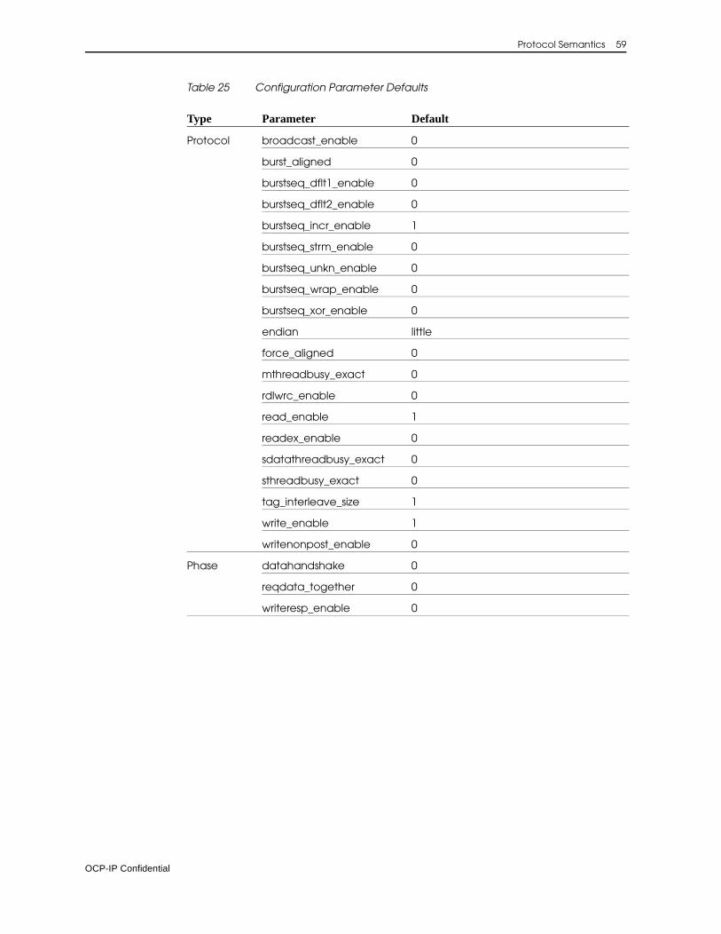
Protocol Semantics 59
Table 25 Configuration Parameter Defaults
Type Parameter Default
Protocol broadcast_enable 0
burst_aligned 0
burstseq_dflt1_enable 0
burstseq_dflt2_enable 0
burstseq_incr_enable 1
burstseq_strm_enable 0
burstseq_unkn_enable 0
burstseq_wrap_enable 0
burstseq_xor_enable 0
endian little
force_aligned 0
mthreadbusy_exact 0
rdlwrc_enable 0
read_enable 1
readex_enable 0
sdatathreadbusy_exact 0
sthreadbusy_exact 0
tag_interleave_size 1
write_enable 1
writenonpost_enable 0
Phase datahandshake 0
reqdata_together 0
writeresp_enable 0
OCP-IP Confidential
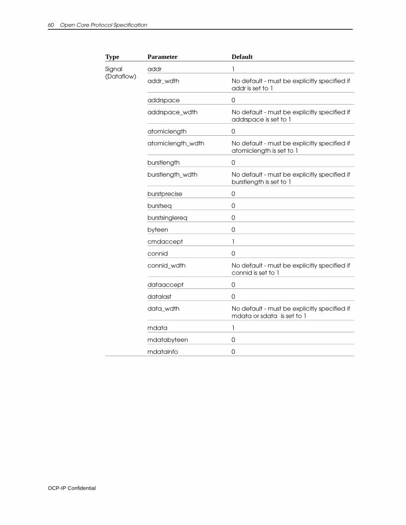
60 Open Core Protocol Specification
Signal(Dataflow)
addr 1
addr_wdth No default - must be explicitly specified if addr is set to 1
addrspace 0
addrspace_wdth No default - must be explicitly specified if addrspace is set to 1
atomiclength 0
atomiclength_wdth No default - must be explicitly specified if atomiclength is set to 1
burstlength 0
burstlength_wdth No default - must be explicitly specified if burstlength is set to 1
burstprecise 0
burstseq 0
burstsinglereq 0
byteen 0
cmdaccept 1
connid 0
connid_wdth No default - must be explicitly specified if connid is set to 1
dataaccept 0
datalast 0
data_wdth No default - must be explicitly specified if mdata or sdata is set to 1
mdata 1
mdatabyteen 0
mdatainfo 0
Type Parameter Default
OCP-IP Confidential
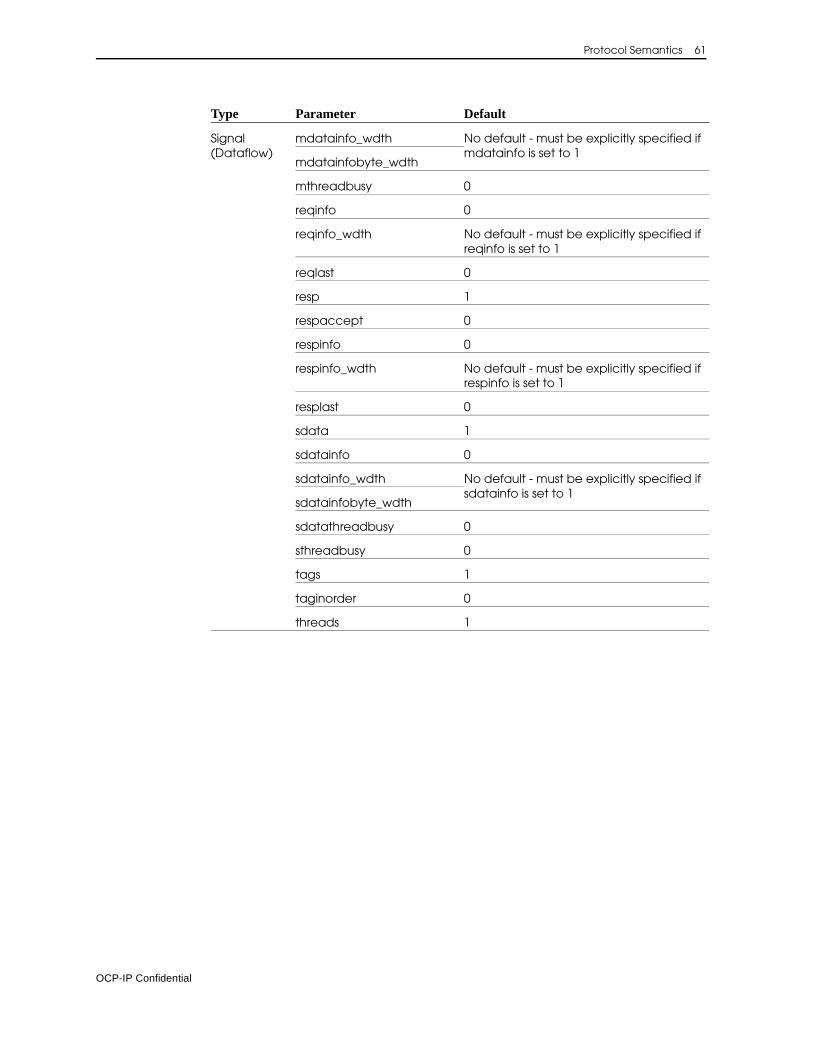
Protocol Semantics 61
Signal(Dataflow)
mdatainfo_wdth No default - must be explicitly specified if mdatainfo is set to 1
mdatainfobyte_wdth
mthreadbusy 0
reqinfo 0
reqinfo_wdth No default - must be explicitly specified if reqinfo is set to 1
reqlast 0
resp 1
respaccept 0
respinfo 0
respinfo_wdth No default - must be explicitly specified if respinfo is set to 1
resplast 0
sdata 1
sdatainfo 0
sdatainfo_wdth No default - must be explicitly specified if sdatainfo is set to 1
sdatainfobyte_wdth
sdatathreadbusy 0
sthreadbusy 0
tags 1
taginorder 0
threads 1
Type Parameter Default
OCP-IP Confidential
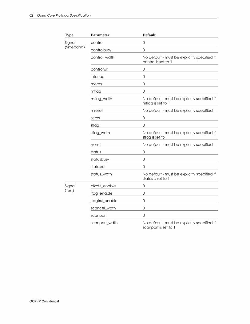
62 Open Core Protocol Specification
Signal(Sideband)
control 0
controlbusy 0
control_wdth No default - must be explicitly specified if control is set to 1
controlwr 0
interrupt 0
merror 0
mflag 0
mflag_wdth No default - must be explicitly specified if mflag is set to 1
mreset No default - must be explicitly specified
serror 0
sflag 0
sflag_wdth No default - must be explicitly specified if sflag is set to 1
sreset No default - must be explicitly specified
status 0
statusbusy 0
statusrd 0
status_wdth No default - must be explicitly specified if status is set to 1
Signal(Test)
clkctrl_enable 0
jtag_enable 0
jtagtrst_enable 0
scanctrl_wdth 0
scanport 0
scanport_wdth No default - must be explicitly specified if scanport is set to 1
Type Parameter Default
OCP-IP Confidential
5 Interface Configuration File
The interface configuration file describes a group of signals, called a bundle. For OCP interfaces, the bundle is pre-defined, and no interface configuration file is required. If you are using an interface other than OCP in your core RTL configuration file, the interface configuration file is required.
Name the file <bundle-name>_intfc.conf where bundle-name is the name given to the bundle that is being defined in the file.
Lexical GrammarThe lexical conventions used in the interface configuration file are:
<name> : (<letter> | ’_’) (<letter> | ’_’ | <digit>)*<letter> : ’a’ .. ’z’ | ’A’ .. ’Z’<digit> : ’0’ .. ’9’
<number> : <integer> | <float>
<integer> : <digit>+
<float> : <mantissa> [<exponent>]<mantissa>: (<integer> ’.’) |(’.’ <integer>) |(<integer> ’.’ <integer>)<exponent>: (’e’ | ’E’) [’+’ | ’-’] <integer>
OCP-IP Confidential
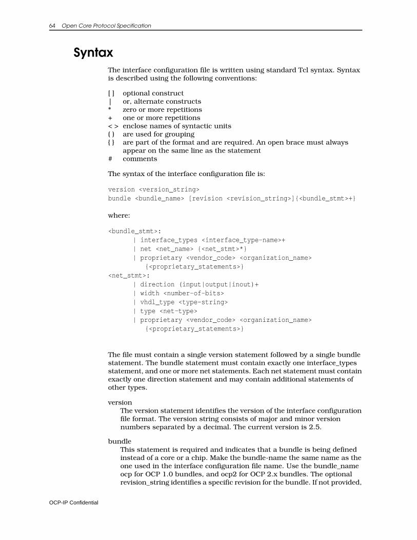
64 Open Core Protocol Specification
SyntaxThe interface configuration file is written using standard Tcl syntax. Syntax is described using the following conventions:
[ ] optional construct| or, alternate constructs* zero or more repetitions+ one or more repetitions< > enclose names of syntactic units( ) are used for grouping{ } are part of the format and are required. An open brace must always
appear on the same line as the statement# comments
The syntax of the interface configuration file is:
version <version_string>bundle <bundle_name> [revision <revision_string>]{<bundle_stmt>+}
where:
<bundle_stmt>: | interface_types <interface_type-name>+| net <net_name> {<net_stmt>*}| proprietary <vendor_code> <organization_name> {<proprietary_statements>}
<net_stmt>: | direction (input|output|inout)+| width <number-of-bits>| vhdl_type <type-string>| type <net-type>| proprietary <vendor_code> <organization_name>
{<proprietary_statements>}
The file must contain a single version statement followed by a single bundle statement. The bundle statement must contain exactly one interface_types statement, and one or more net statements. Each net statement must contain exactly one direction statement and may contain additional statements of other types.
versionThe version statement identifies the version of the interface configuration file format. The version string consists of major and minor version numbers separated by a decimal. The current version is 2.5.
bundle This statement is required and indicates that a bundle is being defined instead of a core or a chip. Make the bundle-name the same name as the one used in the interface configuration file name. Use the bundle_name ocp for OCP 1.0 bundles, and ocp2 for OCP 2.x bundles. The optional revision_string identifies a specific revision for the bundle. If not provided,
OCP-IP Confidential
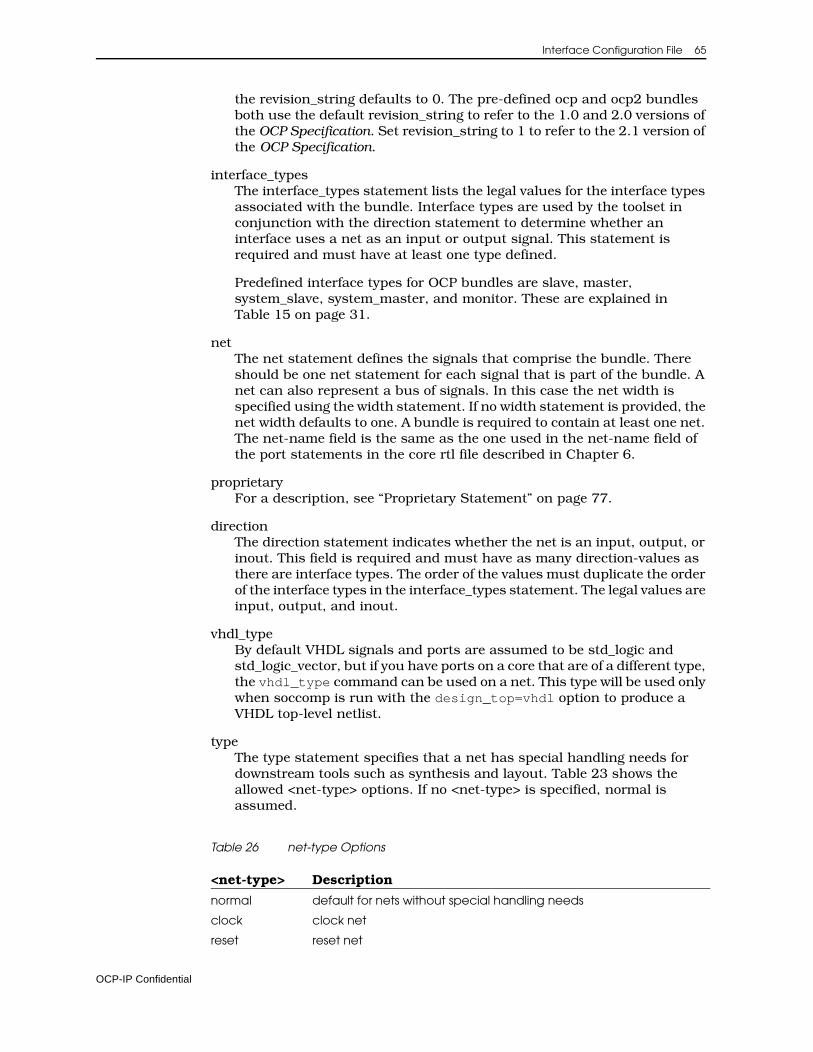
Interface Configuration File 65
the revision_string defaults to 0. The pre-defined ocp and ocp2 bundles both use the default revision_string to refer to the 1.0 and 2.0 versions of the OCP Specification. Set revision_string to 1 to refer to the 2.1 version of the OCP Specification.
interface_typesThe interface_types statement lists the legal values for the interface types associated with the bundle. Interface types are used by the toolset in conjunction with the direction statement to determine whether an interface uses a net as an input or output signal. This statement is required and must have at least one type defined.
Predefined interface types for OCP bundles are slave, master, system_slave, system_master, and monitor. These are explained in Table 15 on page 31.
netThe net statement defines the signals that comprise the bundle. There should be one net statement for each signal that is part of the bundle. A net can also represent a bus of signals. In this case the net width is specified using the width statement. If no width statement is provided, the net width defaults to one. A bundle is required to contain at least one net. The net-name field is the same as the one used in the net-name field of the port statements in the core rtl file described in Chapter 6.
proprietaryFor a description, see “Proprietary Statement” on page 77.
directionThe direction statement indicates whether the net is an input, output, or inout. This field is required and must have as many direction-values as there are interface types. The order of the values must duplicate the order of the interface types in the interface_types statement. The legal values are input, output, and inout.
vhdl_typeBy default VHDL signals and ports are assumed to be std_logic and std_logic_vector, but if you have ports on a core that are of a different type, the vhdl_type command can be used on a net. This type will be used only when soccomp is run with the design_top=vhdl option to produce a VHDL top-level netlist.
typeThe type statement specifies that a net has special handling needs for downstream tools such as synthesis and layout. Table 23 shows the allowed <net-type> options. If no <net-type> is specified, normal is assumed.
Table 26 net-type Options
<net-type> Description
normal default for nets without special handling needs
clock clock net
reset reset net
OCP-IP Confidential
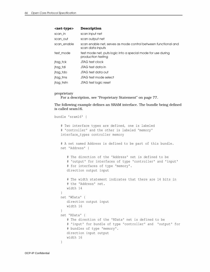
66 Open Core Protocol Specification
proprietaryFor a description, see “Proprietary Statement” on page 77.
The following example defines an SRAM interface. The bundle being defined is called sram16.
bundle "sram16" {
# Two interface types are defined, one is labeled# "controller" and the other is labeled "memory"interface_types controller memory
# A net named Address is defined to be part of this bundle.net "Address" {
# The direction of the "Address" net is defined to be# "output" for interfaces of type "controller" and "input"# for interfaces of type "memory".direction output input
# The width statement indicates that there are 14 bits in# the "Address" net.width 14
}net "WData" {
direction output inputwidth 16
}net "RData" {
# The direction of the "RData" net is defined to be# "input" for bundle of type "controller" and "output" for# bundles of type "memory".direction input outputwidth 16
}
scan_in scan input net
scan_out scan output net
scan_enable scan enable net, serves as mode control between functional and scan data inputs
test_mode test mode net, puts logic into a special mode for use during production testing
jtag_tck JTAG test clock
jtag_tdi JTAG test data in
jtag_tdo JTAG test data out
jtag_tms JTAG test mode select
jtag_trstn JTAG test logic reset
<net-type> Description
OCP-IP Confidential

Interface Configuration File 67
net "We_n" {direction output input
}net "Oe_n" {
direction output input}net "Reset" {
direction output inputtype reset
}# close the bundle}
OCP-IP Confidential

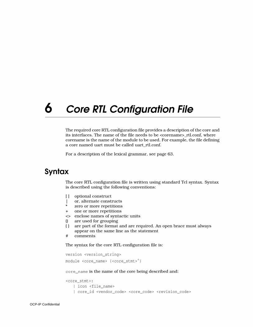
6 Core RTL Configuration File
The required core RTL configuration file provides a description of the core and its interfaces. The name of the file needs to be <corename>_rtl.conf, where corename is the name of the module to be used. For example, the file defining a core named uart must be called uart_rtl.conf.
For a description of the lexical grammar, see page 63.
SyntaxThe core RTL configuration file is written using standard Tcl syntax. Syntax is described using the following conventions:
[ ] optional construct| or, alternate constructs* zero or more repetitions+ one or more repetitions<> enclose names of syntactic units() are used for grouping{ } are part of the format and are required. An open brace must always
appear on the same line as the statement# comments
The syntax for the core RTL configuration file is:
version <version_string>
module <core_name> {<core_stmt>+}
core_name is the name of the core being described and:
<core_stmt>: | icon <file_name>| core_id <vendor_code> <core_code> <revision_code>
OCP-IP Confidential
70 Open Core Protocol Specification
[<description>]| interface <interface_name> bundle <bundle_name> [revision <revision_string>]
[{<interface_body>*}]| addr_region <name> {<addr_region_body>*}| proprietary <vendor_code> <organization_name> {<proprietary_statements>}
The file must contain a single version statement followed by a single module statement. The module statement contains multiple core statements. One core_id must be included. At least one interface statement must be included. One icon statement and one or more addr_region and proprietary statements may also be included.
ComponentsThis section describes the core RTL configuration file components.
Version StatementThe version statement identifies the version of the core RTL configuration file format. The version string consists of major and minor version numbers separated by a period. The current version of the file is 2.5.
Icon StatementThis statement specifies the icon to display on a core. The syntax is:
icon <file_name>
file_name is the name of the graphic file, without any directory names. Store the file in the design directory of the core. For example:
icon "myCore.ppm"
The supported graphic formats are GIF, PPM, and PGM. Graphics should be no larger than 80x80 pixels. Since the text used for the core is white, use a dark background for your icon, otherwise it will be difficult to read.
Core_id StatementThe core_id statement provides identifying information to the tools about the core. This information is required. Syntax of the core_id statement is:
core_id <vendor_code> <core_code> <revision_code> [<description>]
where:
OCP-IP Confidential
Core RTL Configuration File 71
vendor_code An OCP-IP-assigned vendor code that uniquely identifies the core developer. OCP-IP maintains a registry of assigned vendor codes. The allowed range is 0x0000 - 0xFFFF. Use 0x5555 to denote an anonymous vendor. For a list of codes check www.ocpip.org.
core_code A developer-assigned core code that (in combination with the vendor code) uniquely identifies the core. OCP-IP provides suggested values for common cores. Refer to “Defined Core Code Values”. The allowed range is 0x000 - 0xFFF.
revision_code A developer-assigned revision code that can provide core revision information. The allowed range is 0x0 - 0xF.
description An optional Tcl string that provides a short description of the core.
Defined Core Code Values0x000 - 0x7FF: Pre-defined 0x000 - 0x0FF: Memory
Sum values from following choices:ROM:0x0: None0x1: ROM/EPROM0x2: Flash (writable)0x3: ReservedSRAM:0x0: None0x4: Non-pipelined SRAM0x8: Pipelined SRAM0xC: ReservedDRAM:0x00: None0x10: DRAM (trad., page mode, EDO, etc.)0x20: SDRAM (all flavors)0x30: RDRAM (all flavors)0x40: Several0x50: Reserved0x60: Reserved0x70: ReservedBuilt-in DMA:0x00: No0x80: Yes
Values from 0x000 - 0x0FF are defined/reservedExample: Memory controller supporting only SDRAM & Flash would have <cc> = 0x2 + 0x20 = 0x022
0x100 - 0x1FF: General-purpose processorsSum values from following choices plus offset 0x100:
Word size:0x0: 8-bit
OCP-IP Confidential
72 Open Core Protocol Specification
0x1: 16-bit0x2: 32-bit0x3: 64-bit0x4 - 0x7: ReservedEmbedded cache:0x0: No cache0x8: Cache (Instruction, Data, combined, or both)Processor Type:0x00: CPU0x10: DSP0x20: Hybrid0x30: Reserved
Only values from 0x100 - 0x13F are defined/reservedExample: 32-bit CPU with embedded cache would have <cc> = 0x100 + 0x2 + 0x8 + 0x00 = 0x10A
0x200 - 0x2FF: BridgesSum values from following choices plus offset 0x200:
Domain:0x00 - 0x7F: Computing
0x00 - 0x3F: PC’s0x00: ISA (inc. EISA)0x01 - 0x0F: Reserved0x10: PCI (33MHz/32b)0x11: PCI (66MHz/32b)0x12: PCI (33MHz/64b)0x13: PCI (66MHz/64b)0x14 - 0x1F: AGP, etc.0x40 - 0x7F: Reserved
0x80 - 0xBF: Telecom0xA0 - 0xAF: ATM0xA0: Utopia Level 10xA1: Utopia Level 2...
0xC0 - 0xFF: Datacom
0x300 - 0x3FF: Reserved
0x400 - 0x5FF: Other processors(enumerate types: MPEG audio, MPEG video, 2D Graphics, 3D Graphics, packet, cell, QAM, Vitterbi, Huffman, QPSK, etc.)
0x600 - 0x7FF: I/O(enumerate types: Serial UART, Parallel, keyboard, mouse, gameport, USB, 1394, Ethernet 10/100/1000, ATM PHY, NTSC, audio in/out, A/D, D/A, I2C, PCI, AGP, ISA, etc.)
0x800 - 0xFFF: Vendor-defined
OCP-IP Confidential
Core RTL Configuration File 73
(explicitly left up to vendor)
Interface StatementThe interface statement defines and names the interfaces of a core. The inter-face name is required so that cores with multiple interfaces can specify to which interface a particular connection should be made. Syntax for the inter-face statement is:
interface <interface_name> bundle <bundle_name> [revision <revision_string>][{<interface_body>+}]
An interface statement must contain a single interface_type statement and at least one port statement. All other interface body statements are optional
The <bundle_name> must be a defined bundle such as ocp or ocp2 or a bundle specified in an interface configuration file as described on page 63. The optional <revision_string> must match that of the referenced bundle. Different interfaces can refer to different revisions of the same bundle. The pre-defined ocp and ocp2 bundles both use the default revision_string to refer to the 1.0 and 2.0 versions of the OCP Specification. Set revision_string to 1 to refer to the 2.1 version of the OCP Specification.
In the following example, an interface named xyz is defined as an OCP 2.1 bundle. The quotation marks around xyz are not required but help to distin-guish the format.
interface "xyz" bundle ocp2 revision 1
<interface_body>: | interface_type <type_name>| port <port_name> net <net_name> | reference_port <interface_name>.<port_name> net <net_name>| prefix <name>| param <name> <value> [{(<attribute> <value>)*}]| subnet <net_name> <bit_range_list> <subnet_name>| location (n|e|w|s|) <number>| proprietary <vendor_code> <organization_name>
{<proprietary_statements>}
Ports on a core interface may have names that are different than the nets defined in the bundle type for the interface. In this case, each port in the inter-face must be mapped to the net in the bundle with which it is associated. Mapping links the module port <prefix><port_name> with the bundle <net_name>.
The default rules for mapping are that the port_name is the same as the net_name and the prefix is the name of the interface. These rules can be over-ridden using the Port and Prefix statements.
OCP-IP Confidential
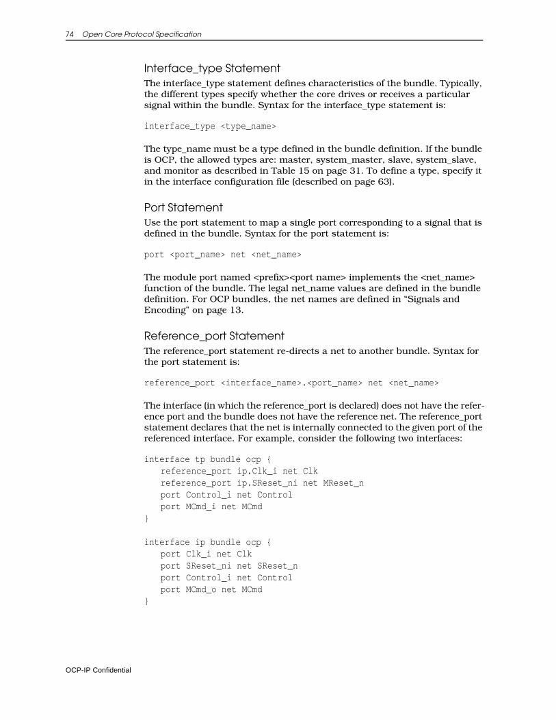
74 Open Core Protocol Specification
Interface_type StatementThe interface_type statement defines characteristics of the bundle. Typically, the different types specify whether the core drives or receives a particular signal within the bundle. Syntax for the interface_type statement is:
interface_type <type_name>
The type_name must be a type defined in the bundle definition. If the bundle is OCP, the allowed types are: master, system_master, slave, system_slave, and monitor as described in Table 15 on page 31. To define a type, specify it in the interface configuration file (described on page 63).
Port StatementUse the port statement to map a single port corresponding to a signal that is defined in the bundle. Syntax for the port statement is:
port <port_name> net <net_name>
The module port named <prefix><port name> implements the <net_name> function of the bundle. The legal net_name values are defined in the bundle definition. For OCP bundles, the net names are defined in “Signals and Encoding” on page 13.
Reference_port StatementThe reference_port statement re-directs a net to another bundle. Syntax for the port statement is:
reference_port <interface_name>.<port_name> net <net_name>
The interface (in which the reference_port is declared) does not have the refer-ence port and the bundle does not have the reference net. The reference_port statement declares that the net is internally connected to the given port of the referenced interface. For example, consider the following two interfaces:
interface tp bundle ocp {reference_port ip.Clk_i net Clkreference_port ip.SReset_ni net MReset_nport Control_i net Controlport MCmd_i net MCmd
}
interface ip bundle ocp {port Clk_i net Clkport SReset_ni net SReset_nport Control_i net Controlport MCmd_o net MCmd
}
OCP-IP Confidential
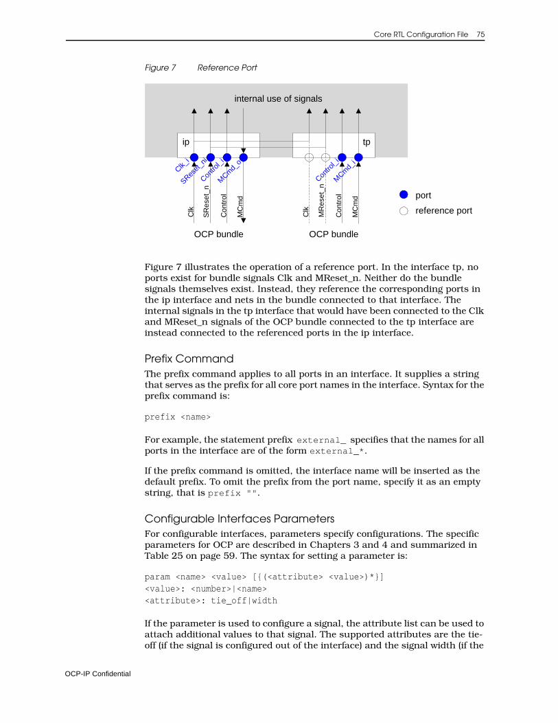
Core RTL Configuration File 75
Figure 7 Reference Port
Figure 7 illustrates the operation of a reference port. In the interface tp, no ports exist for bundle signals Clk and MReset_n. Neither do the bundle signals themselves exist. Instead, they reference the corresponding ports in the ip interface and nets in the bundle connected to that interface. The internal signals in the tp interface that would have been connected to the Clk and MReset_n signals of the OCP bundle connected to the tp interface are instead connected to the referenced ports in the ip interface.
Prefix CommandThe prefix command applies to all ports in an interface. It supplies a string that serves as the prefix for all core port names in the interface. Syntax for the prefix command is:
prefix <name>
For example, the statement prefix external_ specifies that the names for all ports in the interface are of the form external_*.
If the prefix command is omitted, the interface name will be inserted as the default prefix. To omit the prefix from the port name, specify it as an empty string, that is prefix "".
Configurable Interfaces ParametersFor configurable interfaces, parameters specify configurations. The specific parameters for OCP are described in Chapters 3 and 4 and summarized in Table 25 on page 59. The syntax for setting a parameter is:
param <name> <value> [{(<attribute> <value>)*}]<value>: <number>|<name><attribute>: tie_off|width
If the parameter is used to configure a signal, the attribute list can be used to attach additional values to that signal. The supported attributes are the tie-off (if the signal is configured out of the interface) and the signal width (if the
ip tp
Clk_i
SReset
_ni
Contro
l_i
MCm
d_o
Clk
SR
eset
_n
Con
trol
MC
md
Clk
MR
eset
_n
Con
trol
MC
md
internal use of signals
OCP bundle OCP bundle
Contro
l_i
MCm
d_i
port
reference port
OCP-IP Confidential
76 Open Core Protocol Specification
signal is configured into the interface). Specifying the signal width using an attribute attached to the signal parameter is equivalent to using the corre-sponding signal width parameter but the attribute syntax is preferred.
For example, an OCP might be configured to include an interrupt signal as follows.
param interrupt 1
The following example shows the MBurstLength field tied off to a constant value of 4.
param burstlength 0 {tie_off 4}
The following code shows two equivalent ways of setting the address width to 16 bits though the second method is preferred.
param addr_wdth 16
param addr 1 {width 16}
Subnet StatementThe subnet statement assigns names to bits or contiguous bit-fields within a net. Syntax for the subnet statement is:
subnet <net_name> <bit_range_list> <subnet_name><bit_range_list>: <bit_range>[,<bit_range>]*<bit_range>: <bit_number>[:<bit_number>]
The subnet_name is assigned to the bit_range within the given net_name. Bit_range can be either a single bit or a range. Subnet_name is a Tcl string.
For example bit 3 of the MReqInfo net may be assigned the name “cacheable” as follows:
subnet MReqInfo 3 cacheable
Location StatementThe location statement provides a way for the core to indicate where to place this interface when a schematic symbol for the core is drawn. The location is specified as a compass direction of north(n), south(s), east(e), west(w) and a number. The number indicates a percentage from the top or left edge of the block. Syntax for the location statement is:
location (n|e|w|s) <number>
To place an interface on the bottom (south-side) in the middle (50% from the left edge) of the block, for example, use this definition:
location s 50
OCP-IP Confidential
Core RTL Configuration File 77
Address Region StatementThe address region statement specifies address regions within the complete address space of a core. It allows you to give a symbolic name to a region, and to specify its base, size, and behavior.
addr_region <name> {<addr_region_body>*}
where:
<addr_region_body>: addr_base <integer> | addr_size <integer> | addr_space <integer>| proprietary <vendor_code> <organization_name>
{<proprietary_statements>}
• The addr_base statement specifies the base address of the region being defined and is specified as an integer.
• The addr_size statement similarly specifies the size of the region.
• The addr_space statement specifies to which OCP address space the region belongs. If the addr_space statement is omitted, the region belongs to all address spaces.
Proprietary StatementThe proprietary statement enables proprietary extensions of the core RTL configuration file syntax. Standard parsers must be able to ignore the exten-sions, while proprietary parsers can extract additional information about the core. Syntax for the proprietary statement is:
proprietary <vendor_code> <organization_name>{<proprietary_statements>}
The vendor_code uniquely identifies the vendor associated with the propri-etary extensions and is described in more detail on page 71.
The organization_name specifies the name of the organization that specified the extensions. Any number of proprietary statements can be included between the braces but must follow legal Tcl syntax.
The proprietary statement can be included at multiple levels of the syntax hierarchy, allowing it to use scoping to imply context. If multiple proprietary statements are included in a single scope, the parser must process these in an additive fashion.
OCP-IP Confidential
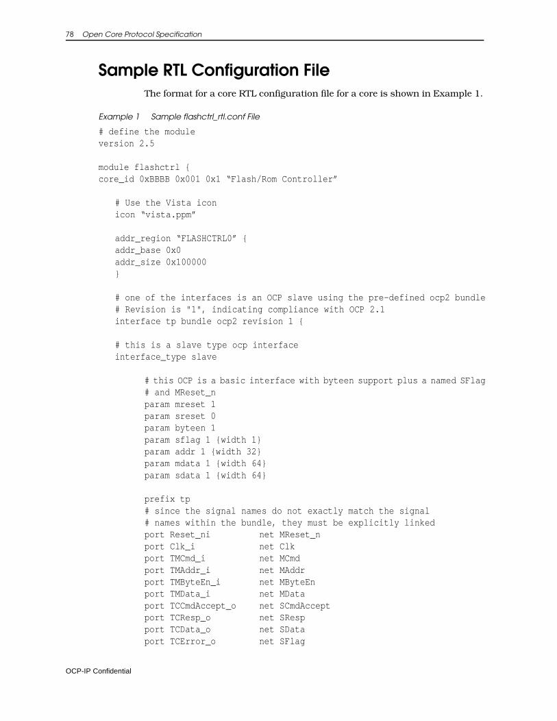
78 Open Core Protocol Specification
Sample RTL Configuration FileThe format for a core RTL configuration file for a core is shown in Example 1.
Example 1 Sample flashctrl_rtl.conf File
# define the moduleversion 2.5
module flashctrl {core_id 0xBBBB 0x001 0x1 “Flash/Rom Controller”
# Use the Vista iconicon “vista.ppm”
addr_region “FLASHCTRL0” {addr_base 0x0addr_size 0x100000}
# one of the interfaces is an OCP slave using the pre-defined ocp2 bundle# Revision is "1", indicating compliance with OCP 2.1interface tp bundle ocp2 revision 1 {
# this is a slave type ocp interfaceinterface_type slave
# this OCP is a basic interface with byteen support plus a named SFlag# and MReset_nparam mreset 1param sreset 0param byteen 1param sflag 1 {width 1}param addr 1 {width 32}param mdata 1 {width 64}param sdata 1 {width 64}
prefix tp# since the signal names do not exactly match the signal# names within the bundle, they must be explicitly linkedport Reset_ni net MReset_n port Clk_i net Clk port TMCmd_i net MCmd port TMAddr_i net MAddr port TMByteEn_i net MByteEn port TMData_i net MData port TCCmdAccept_o net SCmdAccept port TCResp_o net SResp port TCData_o net SData port TCError_o net SFlag
OCP-IP Confidential
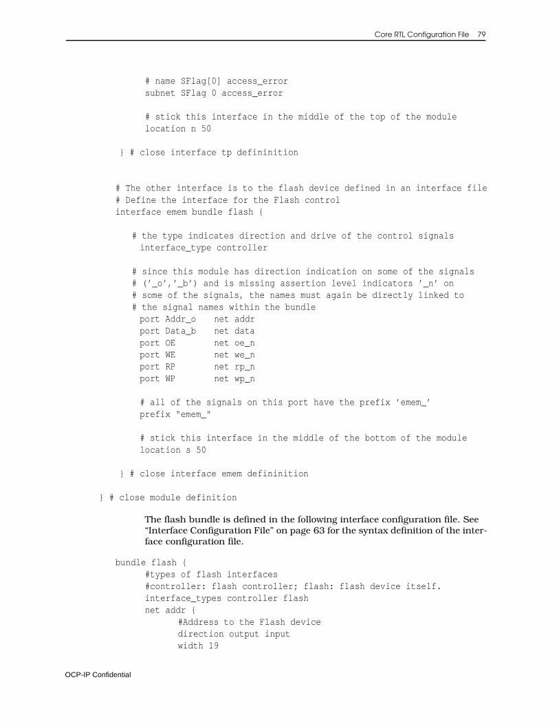
Core RTL Configuration File 79
# name SFlag[0] access_errorsubnet SFlag 0 access_error
# stick this interface in the middle of the top of the modulelocation n 50
} # close interface tp defininition
# The other interface is to the flash device defined in an interface file# Define the interface for the Flash controlinterface emem bundle flash {
# the type indicates direction and drive of the control signals interface_type controller
# since this module has direction indication on some of the signals# (’_o’,’_b’) and is missing assertion level indicators ’_n’ on# some of the signals, the names must again be directly linked to# the signal names within the bundle
port Addr_o net addr port Data_b net data port OE net oe_n port WE net we_n port RP net rp_n port WP net wp_n
# all of the signals on this port have the prefix ’emem_’ prefix "emem_"
# stick this interface in the middle of the bottom of the module location s 50
} # close interface emem defininition
} # close module definition
The flash bundle is defined in the following interface configuration file. See “Interface Configuration File” on page 63 for the syntax definition of the inter-face configuration file.
bundle flash {#types of flash interfaces#controller: flash controller; flash: flash device itself.interface_types controller flashnet addr {
#Address to the Flash devicedirection output inputwidth 19
OCP-IP Confidential
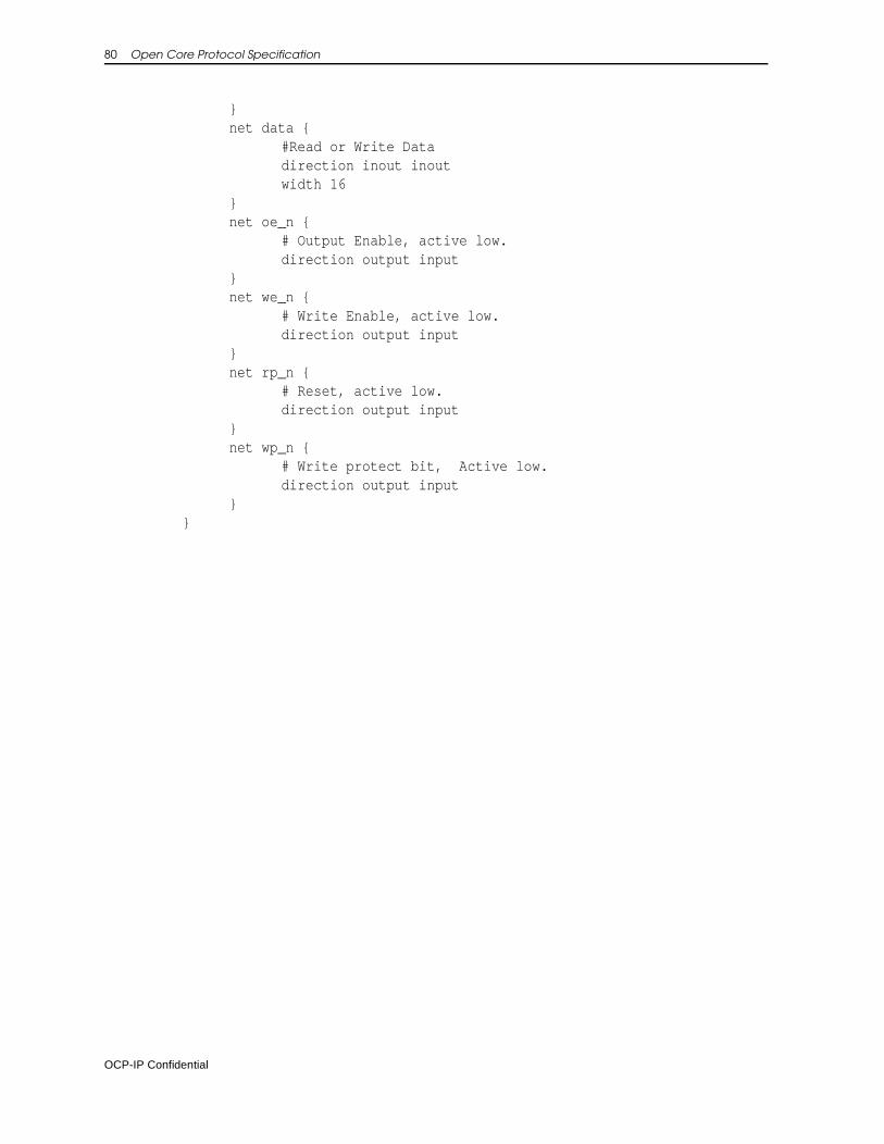
80 Open Core Protocol Specification
}net data { #Read or Write Data
direction inout inoutwidth 16
}net oe_n {
# Output Enable, active low.direction output input
}net we_n {
# Write Enable, active low.direction output input
}net rp_n {
# Reset, active low.direction output input
}net wp_n {
# Write protect bit, Active low.direction output input
}}
OCP-IP Confidential
7 Core Timing
To connect two entities together, allowing communication over an OCP inter-face, the protocols, signals, and pin-level timing must be compatible. This chapter describes how to define interface timing for a core. This process can be applied to OCP and non-OCP interfaces.
Use the core synthesis configuration file to set timing constraints for ports in the core. The file consists of any of the constraint sections: port, max delay, and false path. If the core has additional non-OCP clocks, the file should contain their definitions.
When implementing IP cores in a technology independent manner it is diffi-cult to specify only one timing number for the interface signals, since timing is dependent on technology, library and design tools. The methodology spec-ified in this chapter allows the timing of interface signals to be specified in a technology independent way.
To make your core description technology independent use the technology variables defined in the Core Preparation Guide. The technology variables range from describing the default setup and clock-to-output times for a port to defining a high drive cell in the library.
OCP-IP Confidential
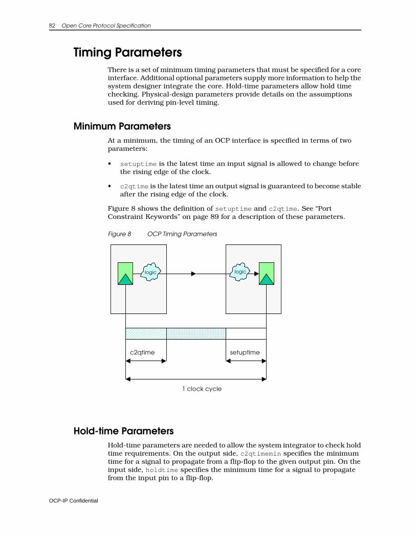
82 Open Core Protocol Specification
Timing ParametersThere is a set of minimum timing parameters that must be specified for a core interface. Additional optional parameters supply more information to help the system designer integrate the core. Hold-time parameters allow hold time checking. Physical-design parameters provide details on the assumptions used for deriving pin-level timing.
Minimum ParametersAt a minimum, the timing of an OCP interface is specified in terms of two parameters:
• setuptime is the latest time an input signal is allowed to change before the rising edge of the clock.
• c2qtime is the latest time an output signal is guaranteed to become stable after the rising edge of the clock.
Figure 8 shows the definition of setuptime and c2qtime. See “Port Constraint Keywords” on page 89 for a description of these parameters.
Figure 8 OCP Timing Parameters
Hold-time ParametersHold-time parameters are needed to allow the system integrator to check hold time requirements. On the output side, c2qtimemin specifies the minimum time for a signal to propagate from a flip-flop to the given output pin. On the input side, holdtime specifies the minimum time for a signal to propagate from the input pin to a flip-flop.
1 clock cycle
c2qtime setuptime
logic logic
OCP-IP Confidential
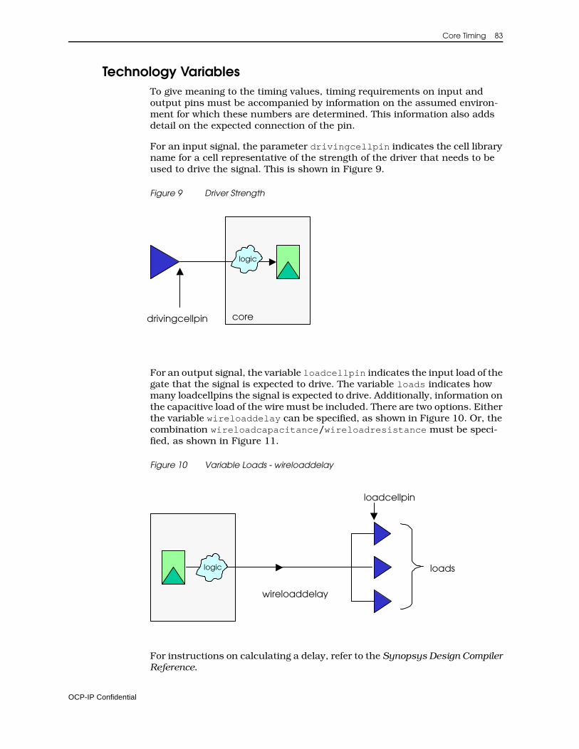
Core Timing 83
Technology VariablesTo give meaning to the timing values, timing requirements on input and output pins must be accompanied by information on the assumed environ-ment for which these numbers are determined. This information also adds detail on the expected connection of the pin.
For an input signal, the parameter drivingcellpin indicates the cell library name for a cell representative of the strength of the driver that needs to be used to drive the signal. This is shown in Figure 9.
Figure 9 Driver Strength
For an output signal, the variable loadcellpin indicates the input load of the gate that the signal is expected to drive. The variable loads indicates how many loadcellpins the signal is expected to drive. Additionally, information on the capacitive load of the wire must be included. There are two options. Either the variable wireloaddelay can be specified, as shown in Figure 10. Or, the combination wireloadcapacitance/wireloadresistance must be speci-fied, as shown in Figure 11.
Figure 10 Variable Loads - wireloaddelay
For instructions on calculating a delay, refer to the Synopsys Design Compiler Reference.
logic
drivingcellpin core
loadslogic
wireloaddelay
loadcellpin
OCP-IP Confidential
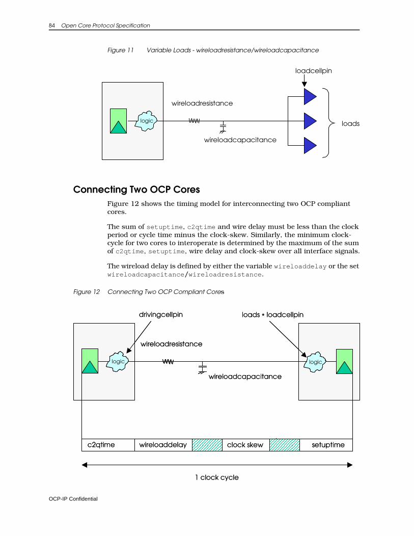
84 Open Core Protocol Specification
Figure 11 Variable Loads - wireloadresistance/wireloadcapacitance
Connecting Two OCP CoresFigure 12 shows the timing model for interconnecting two OCP compliant cores.
The sum of setuptime, c2qtime and wire delay must be less than the clock period or cycle time minus the clock-skew. Similarly, the minimum clock-cycle for two cores to interoperate is determined by the maximum of the sum of c2qtime, setuptime, wire delay and clock-skew over all interface signals.
The wireload delay is defined by either the variable wireloaddelay or the set wireloadcapacitance/wireloadresistance.
Figure 12 Connecting Two OCP Compliant Cores
logic
loadcellpin
loads
wireloadresistance
wireloadcapacitance
logic
loads * loadcellpin
wireloadresistance
wireloadcapacitance
drivingcellpin
logic logic
c2qtime wireloaddelay
1 clock cycle
clock skew setuptime
logiclogic
loads * loadcellpin
wireloadresistance
wireloadcapacitance
drivingcellpin
logiclogic logiclogic
c2qtime wireloaddelay
1 clock cycle
clock skew setuptime
OCP-IP Confidential
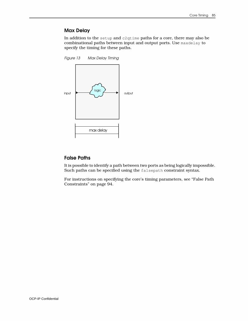
Core Timing 85
Max DelayIn addition to the setup and c2qtime paths for a core, there may also be combinational paths between input and output ports. Use maxdelay to specify the timing for these paths.
Figure 13 Max Delay Timing
False PathsIt is possible to identify a path between two ports as being logically impossible. Such paths can be specified using the falsepath constraint syntax.
For instructions on specifying the core’s timing parameters, see “False Path Constraints” on page 94.
max delay
logicinput output
OCP-IP Confidential
86 Open Core Protocol Specification
Core Synthesis Configuration File The core synthesis configuration file contains the following sections:
VersionSpecifies the current version of the synthesis configuration file format. The current version is 1.3.
Clock Describes clocks brought into the core.
AreaDefines the area in gates of the core.
Port Defines the timing of IP block ports.
Max DelaySpecifies the delay between two ports on a combinational path.
False PathSpecifies that a path between input and output ports is logically impossible.
Syntax ConventionsObserve the following syntax conventions:
• Enclose all expr statements within braces { }, to differentiate between expressions that are to be evaluated while the file is being parsed (without braces) and those that are to be evaluated during synthesis constraint file generation (with braces).
• Although not required by Tcl, enclose strings within quotation marks ““, to show that they are different than keywords.
• Specify keywords using lower case.
Parameter values are specified using Tcl syntax. Expressions can use any of the technology or environment variables, and any of the following variables:
clockperiodThis variable should only be used in calculations of timing values for ports. When evaluating expressions that use $clockperiod, the program will determine which clock the port is relative to, determine its period (in nanoseconds), and apply that value to the equation. For example:
port "in" { setuptime {[expr $clockperiod * .5]}}
OCP-IP Confidential
Core Timing 87
rootclockperiod This variable is set to the period of the main system clock, usually referred to as the root clock. It is typically used when a value needs to be a multiple of the root clock, such as for non-OCP clocks. For example:
clock "myClock" { period {[expr $rootclockperiod * 4]}}
The design_syn.conf file can also use conditional settings of the parameters in the design as outlined by the following arrays. These variables are only used at the time the file is read into the tools.
paramThis array is indexed by the configuration parameters that can be found on a particular instance. Only use param for core_syn.conf files since it is only applicable to the instance being processed. For example:
if { $param("dma_fd") == 1 } { port "T12_ipReset_no" { c2qtime {[expr $clockperiod * 0.7]} }}
chipparamThis array is indexed by the configuration parameters that are defined at the chip or design level. These variables can be used in both the design_syn.conf and core_syn.conf files as they are more global in nature than those specified by param. For example:
if { $chipparam("full") == 1 } { instance "bigcore" { port "in" { setuptime {[expr $clockperiod * 0.7]} } }}
interfaceparam This array is indexed by the interface name and the configuration param-eters that are on an interface. It should only be used for core_syn.conf files since it is only applicable to the interfaces on the instance being pro-cessed. In the following example the interface name is ip.
if { $interfaceparam("ip_respaccept") == 1 } { port "ipMRespAccept_o" { c2qtime {[expr $clockperiod * 21/25]} }}
OCP-IP Confidential
88 Open Core Protocol Specification
Version SectionThe version of the core synthesis configuration file is required. Specify the version with the version command, for example: version 1.3
Clock SectionIf you have non-OCP clocks for an IP block or want to specify the worst-casedelay of any clock (including OCP clocks) used in the core, specify the names of the clocks in the core synthesis configuration file. Use the following syntax to specify the name of the clock and its worstcasedelay:
clock <clockName> {worstcasedelay <delay Value>
}
clockName refers to the name of the port that brings the clock into the core for the core synthesis configuration file. For example:
clock “myClock”
worstcasedelayThe worst case delay value is the longest path through the core or instance for a particular clock. The value is used to check that the core can meet the timing requirements of the current design. To help make this value more portable, you may want to use the technology variable gatedelay. For example:
clock "myClock" { worstcasedelay {[10.5 * $gatedelay]}}
clock "otherClock" { worstcasedelay 5}
Constant values are specified in nanoseconds. For consistency, use expressions that can be interpreted in nanoseconds.
Area SectionThe area is the size in gates of the core or instance. By specifying the size in gates the area can be calculated based on the size of a typical two input nand gate in a particular synthesis library. For example:
area {[expr 20500 / $gatesize]}area 5000
Constant values are specified in two input nand gate equivalents. For consis-tency, use expression that can be interpreted in gates.
OCP-IP Confidential
Core Timing 89
Port Constraints SectionUse the port constraints section to specify the timing parameters. Input port information that can be specified includes the setup time, related clock (non-OCP ports), and driving cell. For output ports, the clock to output times, related clock (non-OCP ports), and the loading information must be supplied.
Port Constraint KeywordsThe keywords that can be used to specify information about port constraints are:
c2qtimeThe c2q (clock to q or clock to output) time is the longest path using worst case timing from a starting point in the core (register or input port) to the output port. This includes the c2qtime of the register. To maintain port-ability, most cores specify this as a percentage of the fastest clock period used while synthesizing the core. For example:
c2qtime {[expr $timescale * 3500]}c2qtime {[expr $clockperiod * 0.25]}
Constant values are specified in nanoseconds. For consistency, use ex-pressions that can be interpreted in nanoseconds.
c2qtimeminThe c2q (clock to q or clock to output) time min is the shortest path using best case timing from a starting point in the core (register or input port) to the output port. This includes the c2qtime of the register. Most cores use the default from the technology section, defaultc2qtimemin. For ex-ample:
c2qtimemin {[expr $timescale * 100]}c2qtimemin {$defaultc2qtimemin}
Constant values are specified in nanoseconds. For consistency, use ex-pressions that can be interpreted in nanoseconds.
clocknameThis is an optional field for all OCP ports and is a string specifying the associated clock portname. For input ports, input delays use this clock as the reference clock. For output ports, output delays use this clock as the reference clock. For example:
clockname “myClock”
drivingcellpinThis variable describes which cell in the synthesis library is expected to be driving the input. To maintain portability set this variable to use one of the technology values of high/medium/lowdrivegatepin.
Values are a string that specifies the logical name of the synthesis library, the cell from the library, and the pin that will be driving an input for the core. The pin is optional. For example:
OCP-IP Confidential
90 Open Core Protocol Specification
drivingcellpin {$mediumdrivegatepin}drivingcellpin "pt25u/nand2/O"
holdtimeThe hold time is the shortest path using best case timing from an input port to any endpoint in the core. Most cores use the default from the tech-nology section, defaultholdtime. For example:
holdtime {[expr $timescale * 100]}holdtime {$defaultholdtime}
Constant values are specified in nanoseconds. For consistency, use ex-pressions that can be interpreted in nanoseconds.
loadcellpinThe name of the load library/cell/pin that this output port is expected to drive. The value is specified to the synthesis tool as the gate to use (along with the number of loads) in its load calculations for output ports of a module. For portability use the default.
Values are a string that specifies the logical name of the synthesis library, the cell from the library, and the pin that the load calculation is derived from. The pin is optional. For example:
loadcellpin "pt25u/nand2/I1"loadcellpin {$defaultloadcellpin}
loadsThe number of loadcellpins that this output port is expected to drive. The value is communicated to the synthesis tool as the number of loads to use in load calculations for output ports of a module. The typical setting for this is the technology value of defaultloads. Values are an expression that evaluates to an integer. For example:
loads 5loads {$defaultloads}
maxfanout This keyword limits the fanout of an input port to a specified number of fanouts. To maintain portability set this variable in terms of the technology variable defaultfanoutload.Constant values are specified in library units. For example:
maxfanout {[expr $defaultfanoutload * 1]}
setuptimeThe longest path using worst case timing from an input port to any end-point in the core. To maintain portability, most cores specify this as a per-centage of the fastest clock period used during synthesis of the core. For example:
setuptime {[expr $timescale * 2500]}setuptime {[expr $clockperiod * 0.25]}
OCP-IP Confidential
Core Timing 91
Constant values are specified in nanoseconds. For consistency, use ex-pressions that can be interpreted in nanoseconds.
wireloaddelayReplaces capacitance/resistance as a way to specify expected delays caused by the interconnect. To maintain portability set this variable to use a technology value of long/medium/shortnetdelay.
The resulting values get added to the worst case clock-to-output times of the ports to anticipate net delays of connections to these ports. To improve the accuracy of the delay calculation cores should use the resistance and capacitance settings.
You cannot specify both wireloaddelay and wireloadresistance/ca-pacitance for the same port. For example:
wireloaddelay {[expr $clockperiod * .25]} wireloaddelay {$mediumnetdelay}
Constant values are specified in nanoseconds. For consistency, use ex-pressions that can be interpreted in nanoseconds.
wireloadresistancewireloadcapacitance
Specify expected loading and resistance caused by the interconnect. If available, specify both resistance and capacitance. To maintain portability set this variable to use one of the technology values of long/medium/shortnetrcresistance/capacitance.
If these constraints are specified they show up as additional loads and re-sistances on output ports of a module. You cannot use both wireloaddelay and wireloadresistance/capacitance for the same port.
Specify constant values as expressions that result in kOhms for resis-tance and picofarads (pf) for capacitance. For example:
wireloadresistance {[expr $resistancescale * .09]} wireloadcapacitance {[expr $capacitancescale * .12]}wireloadresistance {$mediumnetrcresistance} wireloadcapacitance {$mediumnetrccapacitance}
Input Port SyntaxFor input and inout ports (inout ports have both an input and an output defi-nition) use the following syntax:
port <portName> {clockname <clockName>drivingcellpin <drivingCellName>setuptime <Value>holdtime <Value>maxfanout <Value>
}
OCP-IP Confidential
92 Open Core Protocol Specification
Examples In the following example, the clock is not specified since this is an OCP port and is known to be controlled by the OCP clock. If a clock were specified as something other than the OCP clock, an error would result.
port “MCmd_i” {drivingcellpin {$mediumdrivegatepin}setuptime {[expr $clockperiod * 0.2]}
}
In the following example, the setup time is required to be 2ns. Time constants are assumed to be in nanoseconds. Use the timescale variable to convert library units to nanoseconds.
port “MAddr_i” {drivingcellpin {$mediumdrivegatepin}setuptime 2
}
The following example shows how to associate a non OCP clock to a port. The example uses maxfanout to limit the fanout of myInPort to 1. If the logic for myInPort required it to fanout to more than one connection, the synthesis tool would add a buffer to satisfy the maxfanout requirement.
port “myInPort” {clockname “myClock”drivingcellpin {$mediumdrivegatepin}setuptime 2maxfanout {[expr $defaultfanoutload * 1]}
}
Output Port SyntaxFor output and inout ports (inout ports have both an input and an output definition) use the following syntax:
port <portName> {clockname <clockName>loadcellpin <loadCellPinName>loads <Value>wireloadresistance <Value>wireloadcapacitance <Value>wireloaddelay <Value>c2qtime <Value>c2qtimemin <Value>
}
You cannot specify both wireloaddelay and wireloadresistance/capac-itance for the same port.
OCP-IP Confidential
Core Timing 93
Examples In the following example, the clock is not specified since this is an OCP port and is known to be controlled by the OCP clock.
port “SCmdaccept_o”loadcellpin {$defaultloadcellpin}loads {$defaultloads}wireloadresistance {$mediumnetrcresistance}wireloadcapacitance {$mediumnetrccapacitance}c2qtime {[expr $clockperiod * 0.2]}
}
In the following example, the clock to output time is required to be 2 ns. Time constants are assumed to be in nanoseconds. Use the timescale variable to convert library units to nanoseconds.
port “SResp_o”loadcellpin {$defaultloadcellpin}loads {$defaultloads}wireloadresistance {$mediumnetrcresistance}wireloadcapacitance {$mediumnetrccapacitance}c2qtime 2
}
The following example shows how to associate a clock to an output port.
port “myOutPort”clockname “myClock”loadcellpin {$defaultloadcellpin}loads 10wireloaddelay {$longnetdelay}c2qtime {[expr $clockperiod * .2]}
}
InOut Port Exampleport “Signal_io”
drivingcellpin {$mediumdrivegatepin}setuptime {[expr $clockperiod * 0.2]}
}port “Signal_io”
loadcellpin {$defaultloadcellpin}loads {$defaultloads}wireloadresistance {$mediumnetrcresistance}wireloadresistance {$mediumnetrccapacitance}c2qtime {[expr $clockperiod * 0.2]}
}
OCP-IP Confidential
94 Open Core Protocol Specification
Max Delay ConstraintsUsing the max delay constraints you can specify the delay between two ports on a combinational path. This is useful when synthesizing two communi-cating OCP interfaces. The syntax for maxdelay is:
maxdelay {delay <delayValue> fromport <portName> toport <portName>...
}
where: <delayValue> can be a constant or a Tcl expression.
In the following example, a maxdelay of 3 ns is specified for the combinational path between myInPort1 and myOutPort1. A maxdelay of 50% of the clockpe-riod is specified for the path between myInPort2 and myOutPort2. The braces around the expression delay evaluation until the expression is used by the mapping program.
maxdelay {delay 3 fromport “myInPort1” toport “myOutPort1delay {[expr $clockperiod *.5]} fromport “myInPort2” toport “myOutPort2”
}
False Path ConstraintsUsing the false path constraints you can specify that a path between certain input and output ports is logically impossible.
The syntax for falsepath is:
falsepath{fromport <portName> toport <portName>
.
.
.}
In the following example, a falsepath is set up between myInPort1 and myOutPort1 as well as myInPort2 and myOutPort2. This tells the synthesis tool that the path is not logically possible and so it will not try to optimize this path to meet timing.
falsepath {fromport “myInPort1” toport “myOutPort1”fromport “myInPort2” toport “myOutPort2”
}
OCP-IP Confidential
Core Timing 95
Sample Core Synthesis Configuration File The following example shows a complete core synthesis configuration file.
version 1.3port “Reset_ni” {
drivingcellpin {$mediumgatedrivepin}setuptime {[expr $clockperiod * .5]}
}port “MCmd_i” {
drivingcellpin {$mediumgatedrivepin}setuptime {[expr $clockperiod * .9]}
}port “MAddr_i” {
drivingcellpin {$mediumgatedrivepin}setuptime {[expr $clockperiod * .5]}
}port “MWidth_i” {
drivingcellpin {$mediumgatedrivepin}setuptime {[expr $clockperiod * .5]}
}port “MData_i” {
drivingcellpin {$mediumgatedrivepin}setuptime {[expr $clockperiod * .5]}
}port “SCmdAccept_o” {
loadcellpin {$defaultloadcellpin}loads {$defaultloads}wireloaddelay {$mediumnetdelay}c2qtime {[expr $clockperiod * .9]}
}port “SResp_o” {
loadcellpin {$defaultloadcellpin}loads {$defaultloads}wireloaddelay {$mediumnetdelay}c2qtime {[expr $clockperiod * .8]}
}port “SData_o” {
loadcellpin {$defaultloadcellpin}loads {$defaultloads}wireloaddelay {$mediumnetdelay}c2qtime {[expr $clockperiod * .8]}
}maxdelay {
delay 2 fromport “MData_i” toport “SResp_o”
}falsepath {
fromport “MData_i” toport “SData_o”}
OCP-IP Confidential


Part II Guidelines

8 Timing Diagrams
The timing diagrams within this chapter look at signals at strategic points and are not intended to provide full explanations but rather, highlight specific areas of interest. The diagrams are provided solely as examples. For related information about phases, see “Signal Timing and Protocol Phases” on page 36.
Most fields are unspecified whenever their corresponding phase is not asserted. This is indicated by the striped pattern in the waveforms. For example, when MCmd is IDLE the request phase is not asserted, so the values of MAddr, MData, and SCmdAccept are unspecified.
Subscripts on labels in the timing diagrams denote transfer numbers that can be helpful in tracking a transfer across protocol phases.
For a description of timing diagram mnemonics, see Tables 2 and 3 on page 16.
OCP-IP Confidential
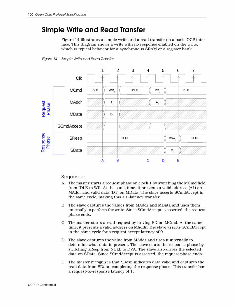
100 Open Core Protocol Specification
Simple Write and Read TransferFigure 14 illustrates a simple write and a read transfer on a basic OCP inter-face. This diagram shows a write with no response enabled on the write, which is typical behavior for a synchronous SRAM or a register bank.
Figure 14 Simple Write and Read Transfer
SequenceA. The master starts a request phase on clock 1 by switching the MCmd field
from IDLE to WR. At the same time, it presents a valid address (A1) on MAddr and valid data (D1) on MData. The slave asserts SCmdAccept in the same cycle, making this a 0-latency transfer.
B. The slave captures the values from MAddr and MData and uses them internally to perform the write. Since SCmdAccept is asserted, the request phase ends.
C. The master starts a read request by driving RD on MCmd. At the same time, it presents a valid address on MAddr. The slave asserts SCmdAccept in the same cycle for a request accept latency of 0.
D. The slave captures the value from MAddr and uses it internally to determine what data to present. The slave starts the response phase by switching SResp from NULL to DVA. The slave also drives the selected data on SData. Since SCmdAccept is asserted, the request phase ends.
E. The master recognizes that SResp indicates data valid and captures the read data from SData, completing the response phase. This transfer has a request-to-response latency of 1.
Clk
MAddr
MCmd
MData
SCmdAccept
SResp
SData
IDLE
A1
WR1
D1
NULL
A2
RD2
DVA2
D2
IDLEIDLE
NULL
2 3 4 5 6 71
Req
uest
Pha
seR
espo
nse
Pha
se
A B C D E
OCP-IP Confidential
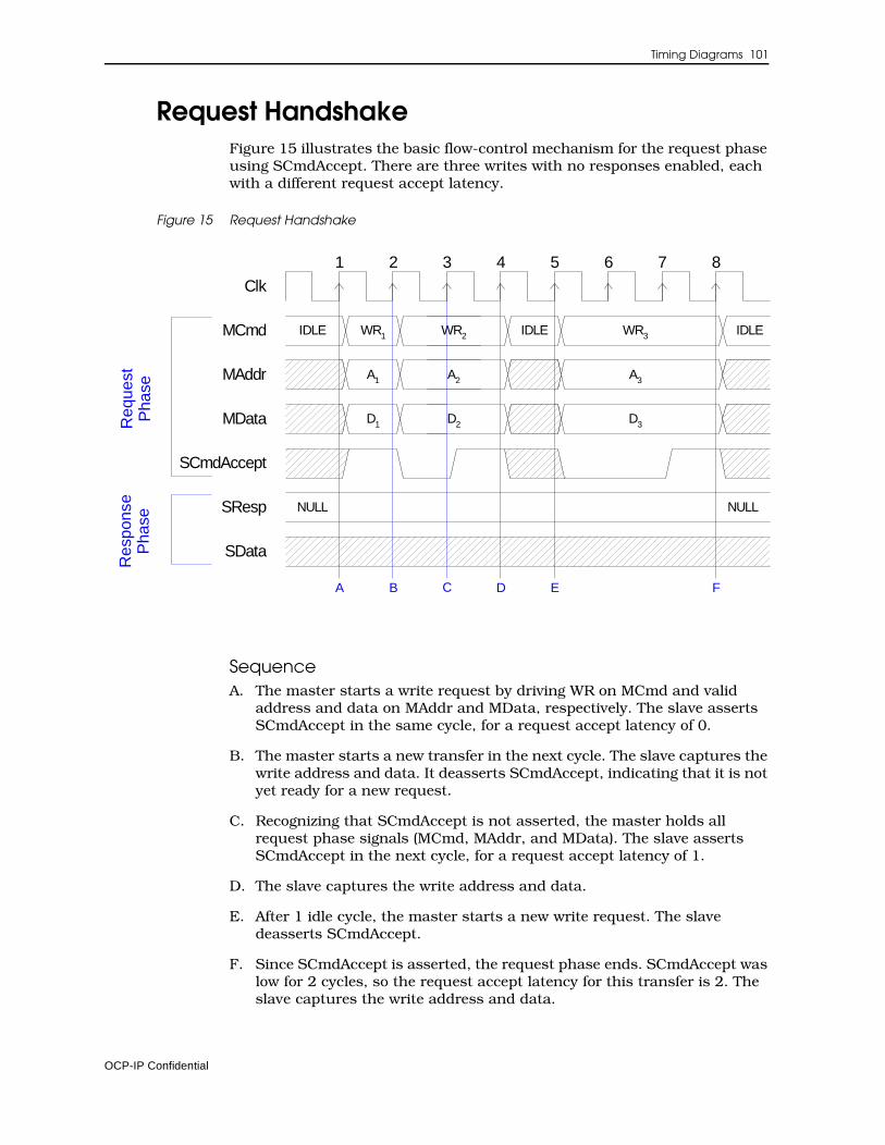
Timing Diagrams 101
Request HandshakeFigure 15 illustrates the basic flow-control mechanism for the request phase using SCmdAccept. There are three writes with no responses enabled, each with a different request accept latency.
Figure 15 Request Handshake
SequenceA. The master starts a write request by driving WR on MCmd and valid
address and data on MAddr and MData, respectively. The slave asserts SCmdAccept in the same cycle, for a request accept latency of 0.
B. The master starts a new transfer in the next cycle. The slave captures the write address and data. It deasserts SCmdAccept, indicating that it is not yet ready for a new request.
C. Recognizing that SCmdAccept is not asserted, the master holds all request phase signals (MCmd, MAddr, and MData). The slave asserts SCmdAccept in the next cycle, for a request accept latency of 1.
D. The slave captures the write address and data.
E. After 1 idle cycle, the master starts a new write request. The slave deasserts SCmdAccept.
F. Since SCmdAccept is asserted, the request phase ends. SCmdAccept was low for 2 cycles, so the request accept latency for this transfer is 2. The slave captures the write address and data.
Clk
MAddr
MCmd
MData
SCmdAccept
SResp
SData
IDLE
NULL
A1
WR1
D1
IDLEWR2
A2
D2
A3
IDLEWR3
D3
NULL
2 3 4 5 6 71 8
A B C D E F
Req
uest
Pha
seR
espo
nse
Pha
se
OCP-IP Confidential
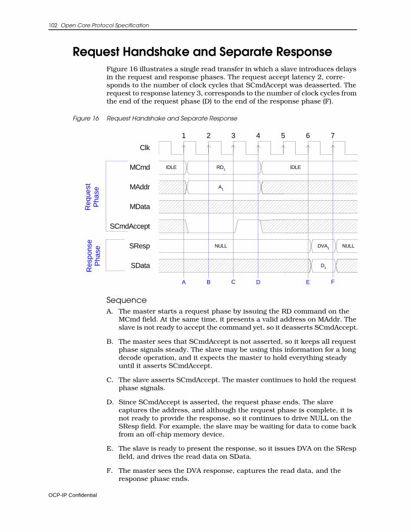
102 Open Core Protocol Specification
Request Handshake and Separate ResponseFigure 16 illustrates a single read transfer in which a slave introduces delays in the request and response phases. The request accept latency 2, corre-sponds to the number of clock cycles that SCmdAccept was deasserted. The request to response latency 3, corresponds to the number of clock cycles from the end of the request phase (D) to the end of the response phase (F).
Figure 16 Request Handshake and Separate Response
SequenceA. The master starts a request phase by issuing the RD command on the
MCmd field. At the same time, it presents a valid address on MAddr. The slave is not ready to accept the command yet, so it deasserts SCmdAccept.
B. The master sees that SCmdAccept is not asserted, so it keeps all request phase signals steady. The slave may be using this information for a long decode operation, and it expects the master to hold everything steady until it asserts SCmdAccept.
C. The slave asserts SCmdAccept. The master continues to hold the request phase signals.
D. Since SCmdAccept is asserted, the request phase ends. The slave captures the address, and although the request phase is complete, it is not ready to provide the response, so it continues to drive NULL on the SResp field. For example, the slave may be waiting for data to come back from an off-chip memory device.
E. The slave is ready to present the response, so it issues DVA on the SResp field, and drives the read data on SData.
F. The master sees the DVA response, captures the read data, and the response phase ends.
Clk
MAddr
MCmd
MData
SCmdAccept
SResp
SData
IDLE
A1
RD1
NULLDVA1NULL
D1
IDLE
Req
uest
Pha
seR
espo
nse
Pha
se
A B C D E
2 3 4 5 6 71
F
OCP-IP Confidential
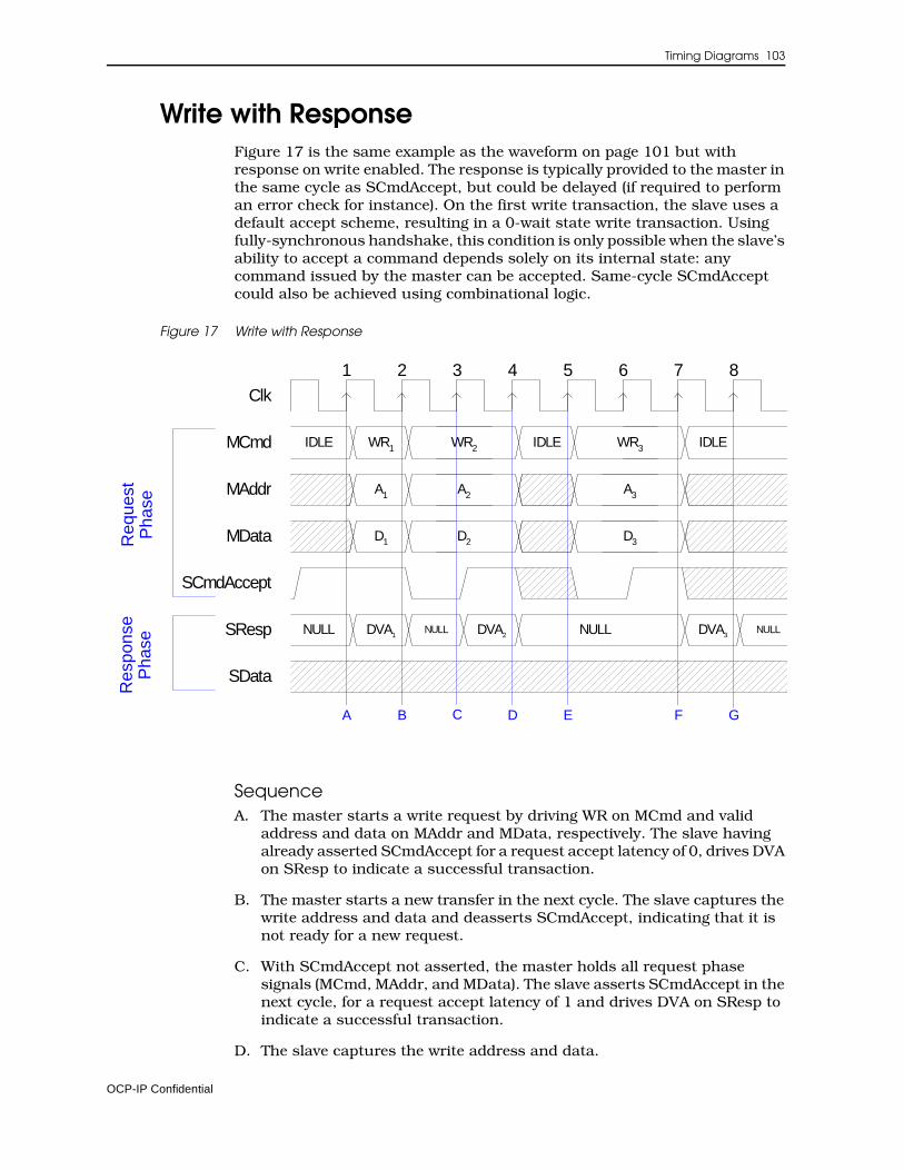
Timing Diagrams 103
Write with ResponseFigure 17 is the same example as the waveform on page 101 but with response on write enabled. The response is typically provided to the master in the same cycle as SCmdAccept, but could be delayed (if required to perform an error check for instance). On the first write transaction, the slave uses a default accept scheme, resulting in a 0-wait state write transaction. Using fully-synchronous handshake, this condition is only possible when the slave’s ability to accept a command depends solely on its internal state: any command issued by the master can be accepted. Same-cycle SCmdAccept could also be achieved using combinational logic.
Figure 17 Write with Response
SequenceA. The master starts a write request by driving WR on MCmd and valid
address and data on MAddr and MData, respectively. The slave having already asserted SCmdAccept for a request accept latency of 0, drives DVA on SResp to indicate a successful transaction.
B. The master starts a new transfer in the next cycle. The slave captures the write address and data and deasserts SCmdAccept, indicating that it is not ready for a new request.
C. With SCmdAccept not asserted, the master holds all request phase signals (MCmd, MAddr, and MData). The slave asserts SCmdAccept in the next cycle, for a request accept latency of 1 and drives DVA on SResp to indicate a successful transaction.
D. The slave captures the write address and data.
Clk
MAddr
MCmd
MData
SCmdAccept
SResp
SData
IDLE
NULL
A1
WR1
D1
IDLEWR2
A2
D2
IDLE
2 3 4 5 6 71 8
A B C D E G
Req
uest
Pha
seR
espo
nse
Pha
se
DVA1NULL DVA2
WR3
A3
D3
DVA3NULLNULL
F
OCP-IP Confidential

104 Open Core Protocol Specification
E. After 1 idle cycle, the master starts a new write request. The slave deasserts SCmdAccept.
F. Since SCmdAccept is asserted, the request phase ends. SCmdAccept was low for 2 cycles, so the request accept latency for this transfer is 2. The slave captures the write address and data. The slave drives DVA on SResp to indicate a successful transaction.
G. The master samples the response.
OCP-IP Confidential
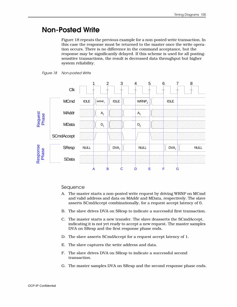
Timing Diagrams 105
Non-Posted Write Figure 18 repeats the previous example for a non-posted write transaction. In this case the response must be returned to the master once the write opera-tion occurs. There is no difference in the command acceptance, but the response may be significantly delayed. If this scheme is used for all posting-sensitive transactions, the result is decreased data throughput but higher system reliability.
Figure 18 Non-posted Write
SequenceA. The master starts a non-posted write request by driving WRNP on MCmd
and valid address and data on MAddr and MData, respectively. The slave asserts SCmdAccept combinationally, for a request accept latency of 0.
B. The slave drives DVA on SResp to indicate a successful first transaction.
C. The master starts a new transfer. The slave deasserts the SCmdAccept, indicating it is not yet ready to accept a new request. The master samples DVA on SResp and the first response phase ends.
D. The slave asserts SCmdAccept for a request accept latency of 1.
E. The slave captures the write address and data.
F. The slave drives DVA on SResp to indicate a successful second transaction.
G. The master samples DVA on SResp and the second response phase ends.
Clk
MAddr
MCmd
MData
SCmdAccept
SResp
SData
IDLE
NULL
A1
WRNP1
D1
IDLE WRNP2
A2
D2
2 3 4 5 6 71 8
A B C D E G
Req
uest
Pha
seR
espo
nse
Pha
se
DVA1 DVA2NULL NULL
IDLE
F
OCP-IP Confidential
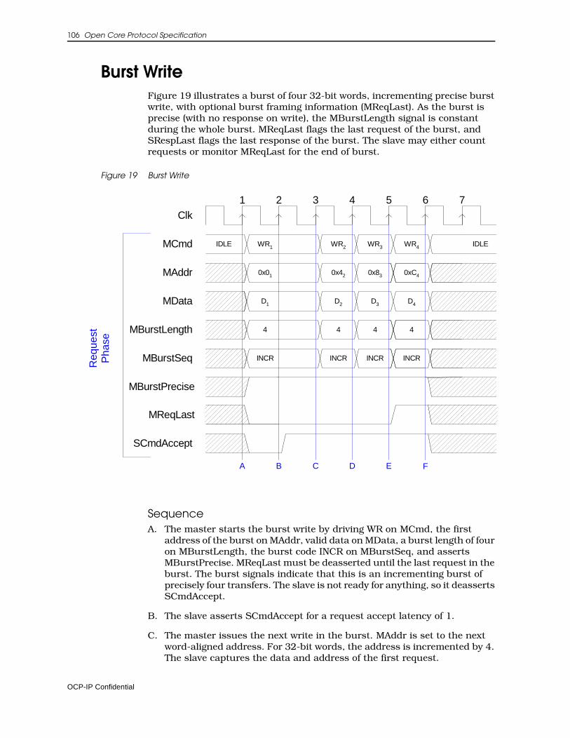
106 Open Core Protocol Specification
Burst WriteFigure 19 illustrates a burst of four 32-bit words, incrementing precise burst write, with optional burst framing information (MReqLast). As the burst is precise (with no response on write), the MBurstLength signal is constant during the whole burst. MReqLast flags the last request of the burst, and SRespLast flags the last response of the burst. The slave may either count requests or monitor MReqLast for the end of burst.
Figure 19 Burst Write
SequenceA. The master starts the burst write by driving WR on MCmd, the first
address of the burst on MAddr, valid data on MData, a burst length of four on MBurstLength, the burst code INCR on MBurstSeq, and asserts MBurstPrecise. MReqLast must be deasserted until the last request in the burst. The burst signals indicate that this is an incrementing burst of precisely four transfers. The slave is not ready for anything, so it deasserts SCmdAccept.
B. The slave asserts SCmdAccept for a request accept latency of 1.
C. The master issues the next write in the burst. MAddr is set to the next word-aligned address. For 32-bit words, the address is incremented by 4. The slave captures the data and address of the first request.
Clk
MAddr
MCmd
MData
SCmdAccept
IDLE
0x01
WR1 WR2
0x83 0xC4
WR4
D4
IDLE
D1
0x42
WR3
D2 D3
MBurstSeq INCR INCR INCRINCR
Req
uest
Pha
se
2 3 4 5 6 71
MBurstLength 4 44 4
MReqLast
MBurstPrecise
B C D E FA
OCP-IP Confidential
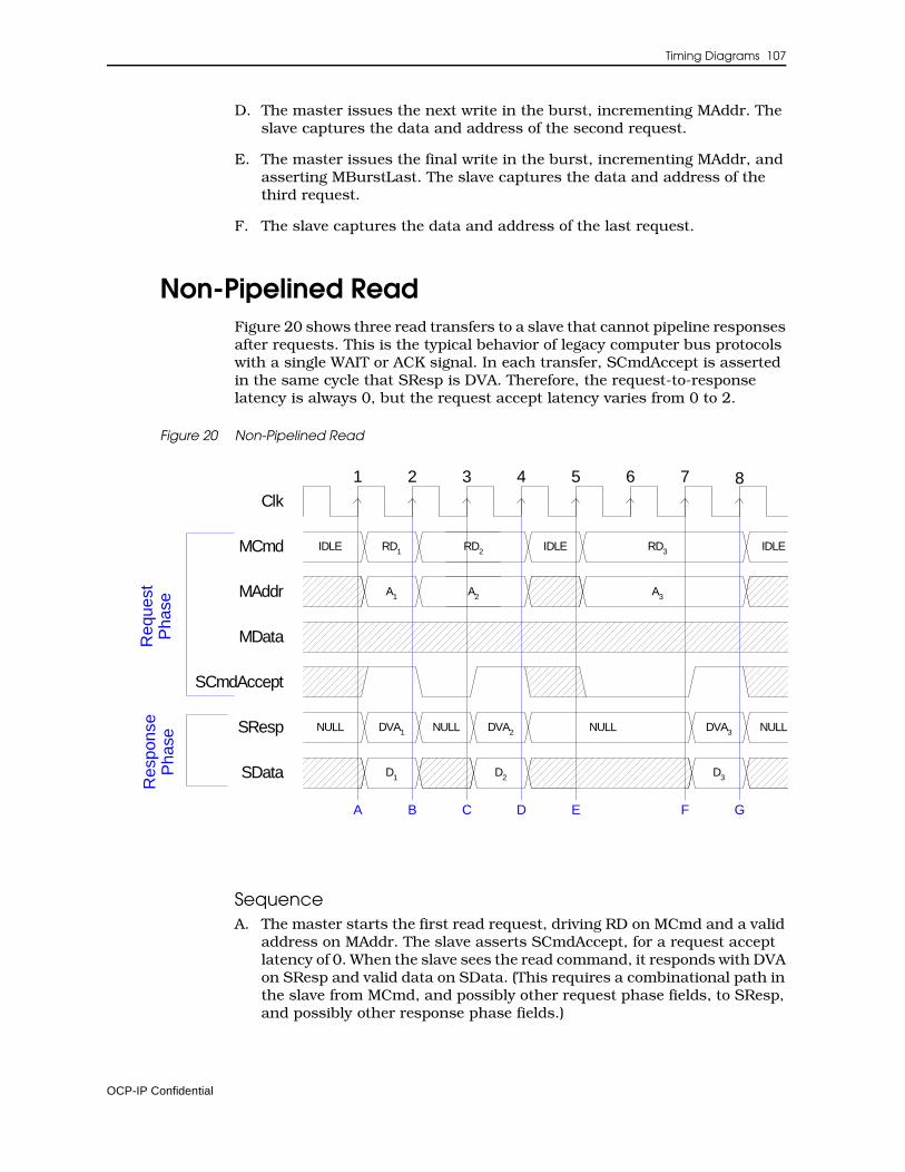
Timing Diagrams 107
D. The master issues the next write in the burst, incrementing MAddr. The slave captures the data and address of the second request.
E. The master issues the final write in the burst, incrementing MAddr, and asserting MBurstLast. The slave captures the data and address of the third request.
F. The slave captures the data and address of the last request.
Non-Pipelined ReadFigure 20 shows three read transfers to a slave that cannot pipeline responses after requests. This is the typical behavior of legacy computer bus protocols with a single WAIT or ACK signal. In each transfer, SCmdAccept is asserted in the same cycle that SResp is DVA. Therefore, the request-to-response latency is always 0, but the request accept latency varies from 0 to 2.
Figure 20 Non-Pipelined Read
SequenceA. The master starts the first read request, driving RD on MCmd and a valid
address on MAddr. The slave asserts SCmdAccept, for a request accept latency of 0. When the slave sees the read command, it responds with DVA on SResp and valid data on SData. (This requires a combinational path in the slave from MCmd, and possibly other request phase fields, to SResp, and possibly other response phase fields.)
Clk
MAddr
MCmd
MData
SCmdAccept
SResp
SData
IDLE
NULL
A1
RD1 IDLERD2
A2 A3
IDLERD3
DVA1 NULL NULLDVA2 DVA3NULL
D1 D2 D3
Req
uest
Pha
seR
espo
nse
Pha
se
2 3 4 5 6 71 8
A B C D E F G
OCP-IP Confidential
108 Open Core Protocol Specification
B. The master launches another read request. It also sees that SResp is DVA and captures the read data from SData. The slave is not ready to respond to the new request, so it deasserts SCmdAccept.
C. The master sees that SCmdAccept is low and extends the request phase. The slave is now ready to respond in the next cycle, so it simultaneously asserts SCmdAccept and drives DVA on SResp and the selected data on SData. The request accept latency is 1.
D. Since SCmdAccept is asserted, the request phase ends. The master sees that SResp is now DVA and captures the data.
E. The master launches a third read request. The slave deasserts SCmdAccept.
F. The slave asserts SCmdAccept after 2 cycles, so the request accept latency is 2. It also drives DVA on SResp and the read data on SData.
G. The master sees that SCmdAccept is asserted, ending the request phase. It also sees that SResp is now DVA and captures the data.
OCP-IP Confidential
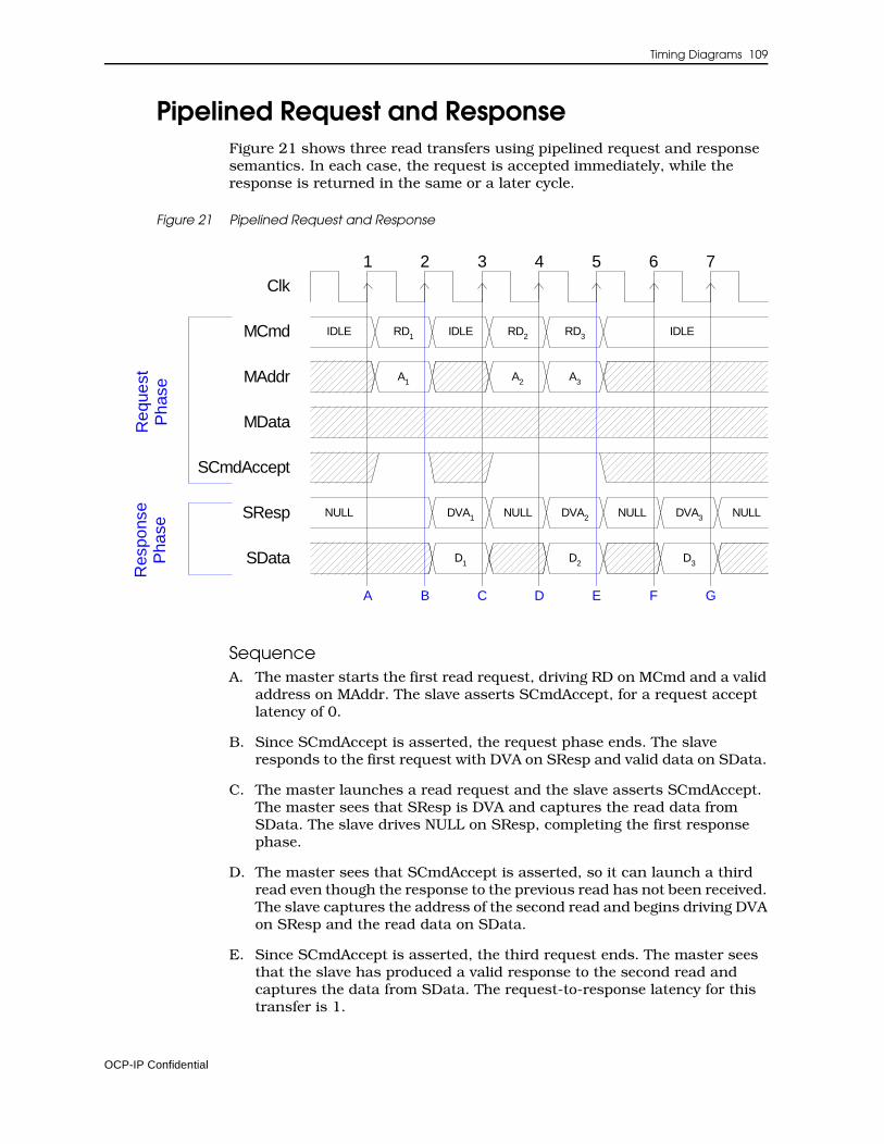
Timing Diagrams 109
Pipelined Request and ResponseFigure 21 shows three read transfers using pipelined request and response semantics. In each case, the request is accepted immediately, while the response is returned in the same or a later cycle.
Figure 21 Pipelined Request and Response
SequenceA. The master starts the first read request, driving RD on MCmd and a valid
address on MAddr. The slave asserts SCmdAccept, for a request accept latency of 0.
B. Since SCmdAccept is asserted, the request phase ends. The slave responds to the first request with DVA on SResp and valid data on SData.
C. The master launches a read request and the slave asserts SCmdAccept. The master sees that SResp is DVA and captures the read data from SData. The slave drives NULL on SResp, completing the first response phase.
D. The master sees that SCmdAccept is asserted, so it can launch a third read even though the response to the previous read has not been received. The slave captures the address of the second read and begins driving DVA on SResp and the read data on SData.
E. Since SCmdAccept is asserted, the third request ends. The master sees that the slave has produced a valid response to the second read and captures the data from SData. The request-to-response latency for this transfer is 1.
Clk
MAddr
MCmd
MData
SCmdAccept
SResp
SData
IDLE
NULL
A1
RD1 IDLE
A3
RD3
DVA3 NULL
D3
IDLE
DVA1
D1
A2
RD2
DVA2
D2
NULL
2 3 4 5 6 71
Req
uest
Pha
seR
espo
nse
Pha
se
B C D E F GA
NULL
OCP-IP Confidential
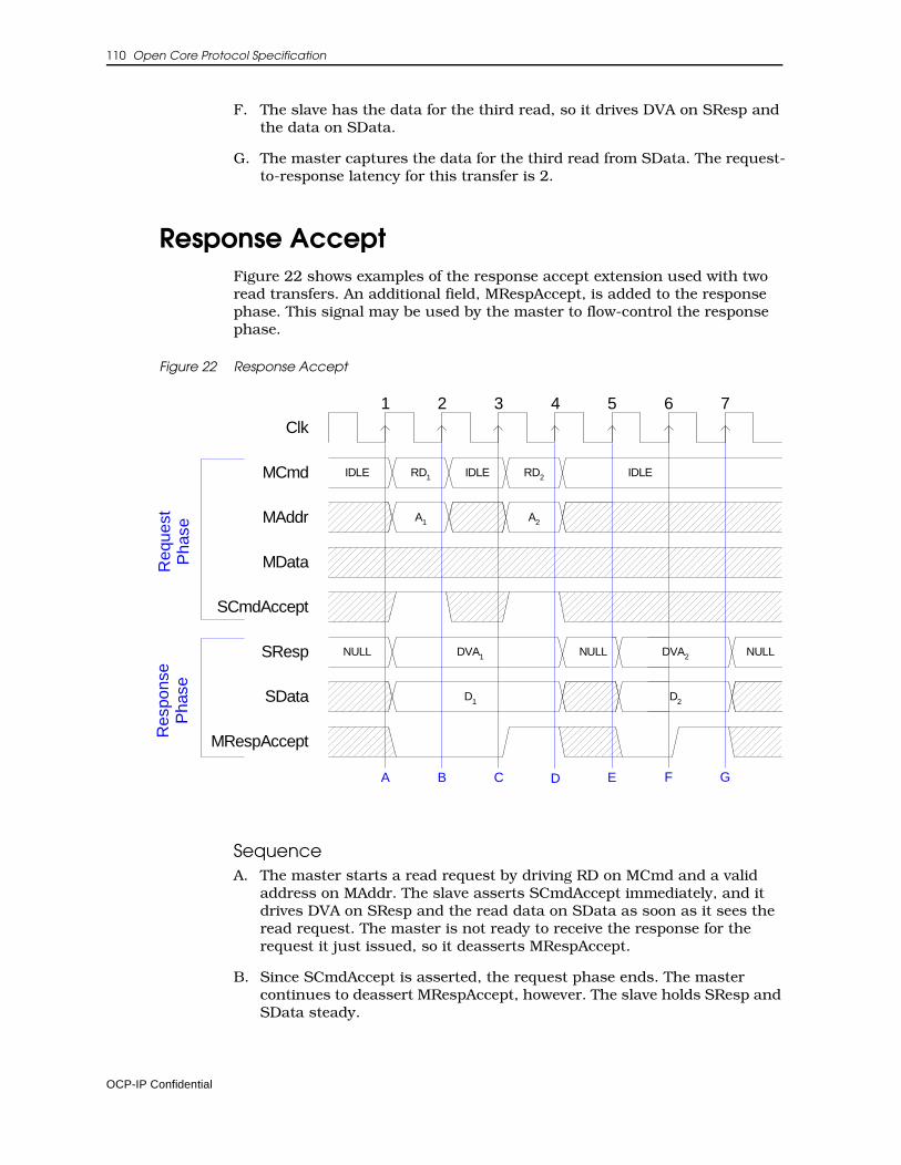
110 Open Core Protocol Specification
F. The slave has the data for the third read, so it drives DVA on SResp and the data on SData.
G. The master captures the data for the third read from SData. The request-to-response latency for this transfer is 2.
Response AcceptFigure 22 shows examples of the response accept extension used with two read transfers. An additional field, MRespAccept, is added to the response phase. This signal may be used by the master to flow-control the response phase.
Figure 22 Response Accept
SequenceA. The master starts a read request by driving RD on MCmd and a valid
address on MAddr. The slave asserts SCmdAccept immediately, and it drives DVA on SResp and the read data on SData as soon as it sees the read request. The master is not ready to receive the response for the request it just issued, so it deasserts MRespAccept.
B. Since SCmdAccept is asserted, the request phase ends. The master continues to deassert MRespAccept, however. The slave holds SResp and SData steady.
Clk
MAddr
MCmd
MData
SCmdAccept
SResp
SData
IDLE
NULL
A1
RD1 IDLE
NULL
IDLE
A2
RD2
MRespAccept
D1
DVA1 DVA2
D2
Req
uest
Pha
seR
espo
nse
Pha
se
2 3 4 5 6 71
A B C D E F G
NULL
OCP-IP Confidential
Timing Diagrams 111
C. The master starts a second read request and is ready for the response from its first request, so it asserts MRespAccept. This corresponds to a response accept latency of 2.
D. Since SCmdAccept is asserted, the request phase ends. The master captures the data for the first read from the slave. Since MRespAccept is asserted, the response phase ends. The slave is not ready to respond to the second read, so it drives NULL on SResp.
E. The slave responds to the second read by driving DVA on SResp and the read data on SData. The master is not ready for the response, however, so it deasserts RespAccept.
F. The master asserts MRespAccept, for a response accept latency of 1.
G. The master captures the data for the second read from the slave. Since MRespAccept is asserted, the response phase ends.
OCP-IP Confidential
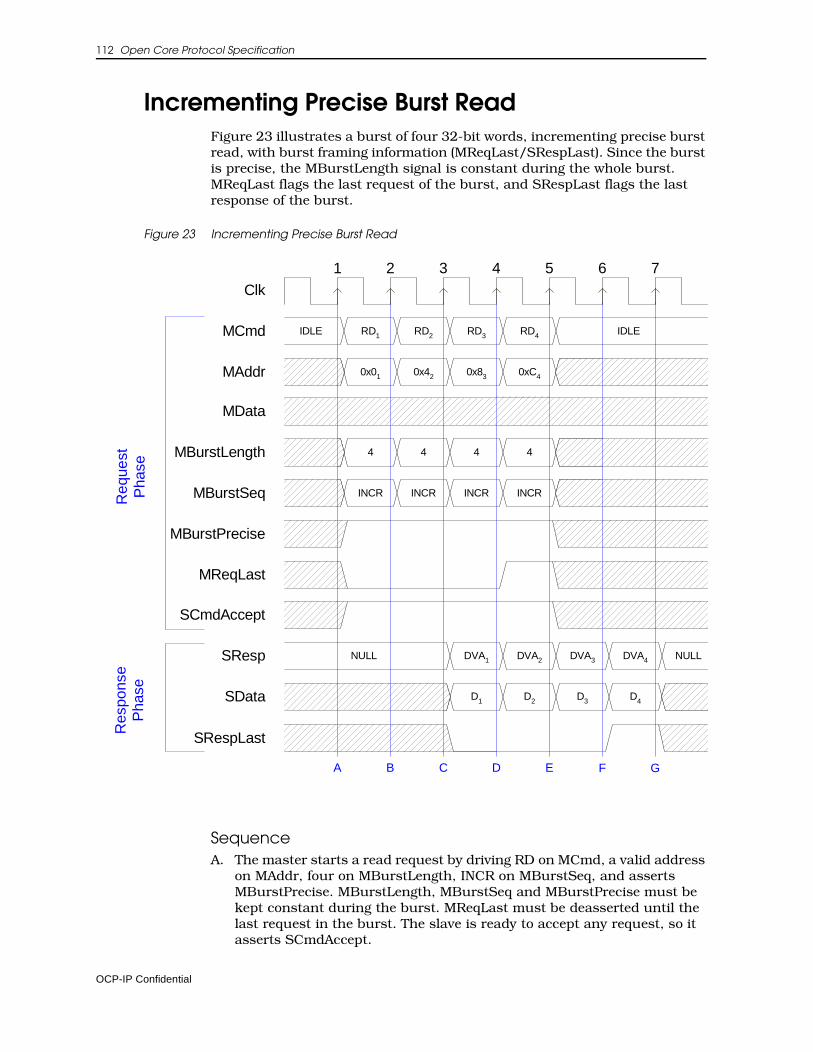
112 Open Core Protocol Specification
Incrementing Precise Burst ReadFigure 23 illustrates a burst of four 32-bit words, incrementing precise burst read, with burst framing information (MReqLast/SRespLast). Since the burst is precise, the MBurstLength signal is constant during the whole burst. MReqLast flags the last request of the burst, and SRespLast flags the last response of the burst.
Figure 23 Incrementing Precise Burst Read
SequenceA. The master starts a read request by driving RD on MCmd, a valid address
on MAddr, four on MBurstLength, INCR on MBurstSeq, and asserts MBurstPrecise. MBurstLength, MBurstSeq and MBurstPrecise must be kept constant during the burst. MReqLast must be deasserted until the last request in the burst. The slave is ready to accept any request, so it asserts SCmdAccept.
Clk
MAddr
MCmd
MData
SCmdAccept
SResp
SData
IDLE
0x01
RD1 RD2
0x83 0xC4
RD4
DVA4 NULL
D4
IDLE
DVA1
D1
0x42
RD3
DVA2
D2 D3
DVA3
MBurstLength 4 4 44
NULL
Req
uest
Pha
seR
espo
nse
Pha
se
2 3 4 5 6 71
MBurstSeq INCR INCR INCRINCR
MBurstPrecise
MReqLast
SRespLast
D E F GA B C
OCP-IP Confidential

Timing Diagrams 113
B. The master issues the next read in the burst. MAddr is set to the next word-aligned address (incremented by 4 in this case). The slave captures the address of the first request and keeps SCmdAccept asserted.
C. The master issues the next read in the burst. MAddr is set to the next word-aligned address (incremented by 4 in this case). The slave captures the address of the second request and keeps SCmdAccept asserted. The slave responds to the first read by driving DVA on SResp and the read data on SData.
D. The master issues the last request of the burst, incrementing MAddr and asserting MReqLast. The master also captures the data for the first read from the slave. The slave responds to the second request, and captures the address of the third request.
E. The master captures the data for the second read from the slave. The slave responds to the third request and captures the address of the fourth.
F. The master captures the data for the third read from the slave. The slave responds to the fourth request and asserts SRespLast to indicate the last response of the burst.
G. The master captures the data for the last read from the slave, ending the last response phase.
OCP-IP Confidential
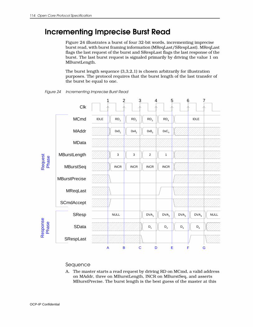
114 Open Core Protocol Specification
Incrementing Imprecise Burst ReadFigure 24 illustrates a burst of four 32-bit words, incrementing imprecise burst read, with burst framing information (MReqLast/SRespLast). MReqLast flags the last request of the burst and SRespLast flags the last response of the burst. The last burst request is signaled primarily by driving the value 1 on MBurstLength.
The burst length sequence (3,3,2,1) is chosen arbitrarily for illustration purposes. The protocol requires that the burst length of the last transfer of the burst be equal to one.
Figure 24 Incrementing Imprecise Burst Read
SequenceA. The master starts a read request by driving RD on MCmd, a valid address
on MAddr, three on MBurstLength, INCR on MBurstSeq, and asserts MBurstPrecise. The burst length is the best guess of the master at this
Clk
MAddr
MCmd
MData
SCmdAccept
SResp
SData
IDLE
0x01
RD1 RD2
0x83 0xC4
RD4
DVA4 NULL
D4
IDLE
DVA1
D1
0x42
RD3
DVA2
D2 D3
DVA3
MBurstLength 3 2 13
NULL
Req
uest
Pha
seR
espo
nse
Pha
se
2 3 4 5 6 71
MBurstSeq INCR INCR INCRINCR
MBurstPrecise
MReqLast
SRespLast
D E F GB CA
OCP-IP Confidential

Timing Diagrams 115
point. MBurstSeq and MBurstPrecise are kept constant during the burst. MReqLast must be deasserted until the last request in the burst. The slave is ready to accept any request, so it asserts SCmdAccept.
B. The master issues the next read in the burst. MAddr is set to the next word-aligned address (incremented by 4 in this case). The MBurstLength is set to three, since the master knows the burst is longer than it originally thought. The slave captures the address of the first request and keeps SCmdAccept asserted.
C. The master issues the next read in the burst. MAddr is set to the next word-aligned address (incremented by 4 in this case). The MBurstLength is set to two. The slave captures the address of the second request, and keeps SCmdAccept asserted. The slave responds to the first read by driving DVA on SResp and the read data on SData.
D. The master issues the last request of the burst, incrementing MAddr, setting MBurstLength to one, and asserting MReqLast. The master also captures the data for the first read from the slave. The slave responds to the second request and captures the address of the last request.
E. The master captures the data for the second read from the slave. The slave responds to the third request.
F. The master captures the data for the third read from the slave. The slave responds to the fourth request and asserts SRespLast to indicate the last response of the burst.
G. The master captures the data for the last read from the slave, ending the last response phase.
OCP-IP Confidential
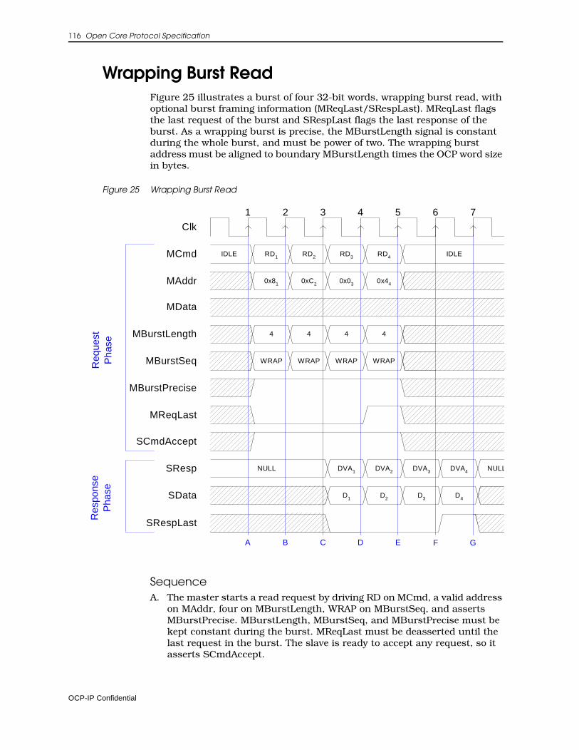
116 Open Core Protocol Specification
Wrapping Burst ReadFigure 25 illustrates a burst of four 32-bit words, wrapping burst read, with optional burst framing information (MReqLast/SRespLast). MReqLast flags the last request of the burst and SRespLast flags the last response of the burst. As a wrapping burst is precise, the MBurstLength signal is constant during the whole burst, and must be power of two. The wrapping burst address must be aligned to boundary MBurstLength times the OCP word size in bytes.
Figure 25 Wrapping Burst Read
SequenceA. The master starts a read request by driving RD on MCmd, a valid address
on MAddr, four on MBurstLength, WRAP on MBurstSeq, and asserts MBurstPrecise. MBurstLength, MBurstSeq, and MBurstPrecise must be kept constant during the burst. MReqLast must be deasserted until the last request in the burst. The slave is ready to accept any request, so it asserts SCmdAccept.
Clk
MAddr
MCmd
MData
SCmdAccept
SResp
SData
IDLE
0x81
RD1 RD2
0x03 0x44
RD4
DVA4 NULL
D4
IDLE
DVA1
D1
0xC2
RD3
DVA2
D2 D3
DVA3
MBurstLength 4 4 44
NULL
Req
uest
Pha
seR
espo
nse
Pha
se
2 3 4 5 6 71
MBurstSeq WRAP WRAP WRAPWRAP
MBurstPrecise
MReqLast
SRespLast
D E F GA B C
OCP-IP Confidential
Timing Diagrams 117
B. The master issues the next read in the burst. MAddr is set to the next word-aligned address (incremented by 4 in this case). The slave captures the address of the first request, and keeps SCmdAccept asserted.
C. If incremented, the next address would be 0x10. Since the first transfer was from address 0x8 and the burst length is 4, the addresses must be between 0 and 0xF. The master wraps the MAddr to 0, which is the closest alignment boundary. (If the first address were 0x14, the address would wrap to 0x10, rather than 0x20.) The slave captures the address of the second request, and keeps SCmdAccept asserted. The slave responds to the first read by driving DVA on SResp and valid data on SData.
D. The master issues the last request of the burst, incrementing MAddr and asserting MReqLast. The master also captures the data for the first read from the slave. The slave responds to the second request and captures the address of the third.
E. The master captures the data for the second read from the slave. The slave responds to the third request and captures the address of the fourth.
F. The master captures the data for the third read from the slave. The slave responds to the fourth request and asserts SRespLast to indicate the last response of the burst.
G. The master captures the data for the last read from the slave, ending the last response phase.
OCP-IP Confidential
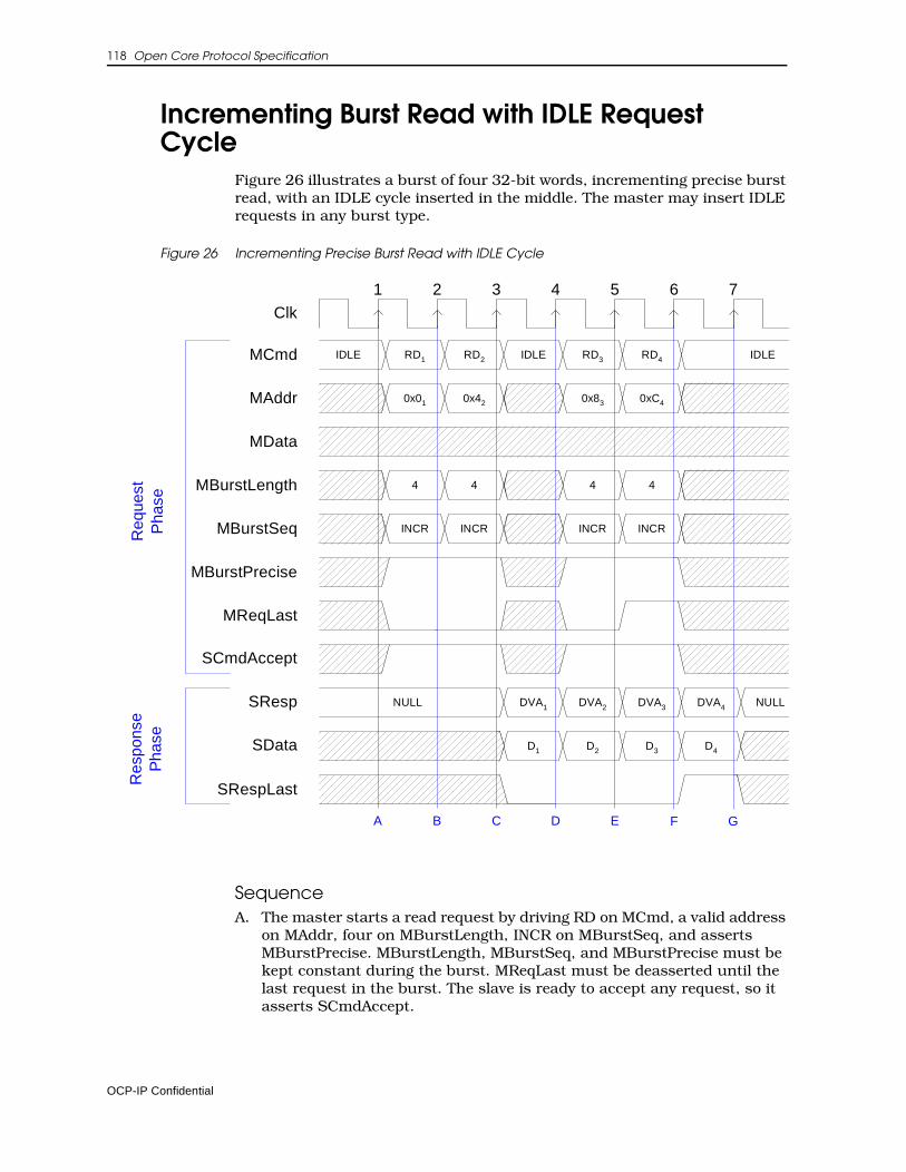
118 Open Core Protocol Specification
Incrementing Burst Read with IDLE Request Cycle
Figure 26 illustrates a burst of four 32-bit words, incrementing precise burst read, with an IDLE cycle inserted in the middle. The master may insert IDLE requests in any burst type.
Figure 26 Incrementing Precise Burst Read with IDLE Cycle
SequenceA. The master starts a read request by driving RD on MCmd, a valid address
on MAddr, four on MBurstLength, INCR on MBurstSeq, and asserts MBurstPrecise. MBurstLength, MBurstSeq, and MBurstPrecise must be kept constant during the burst. MReqLast must be deasserted until the last request in the burst. The slave is ready to accept any request, so it asserts SCmdAccept.
Clk
MAddr
MCmd
MData
SCmdAccept
SResp
SData
IDLE
0x01
RD1 RD2
0x83 0xC4
RD4
DVA4 NULL
D4
IDLE
DVA1
D1
0x42
RD3
DVA2
D2 D3
DVA3
MBurstLength 4 4 44
NULL
Req
uest
Pha
seR
espo
nse
Pha
se
MBurstSeq INCR INCR INCRINCR
MBurstPrecise
MReqLast
SRespLast
G
IDLE
E F
1 2 3 4 5 6 7
DB CA
OCP-IP Confidential
Timing Diagrams 119
B. The master issues the next read in the burst. MAddr is set to the next word-aligned address (incremented by 4 in this case). The slave captures the address of the first request and keeps SCmdAccept asserted.
C. The master inserts an IDLE request in the middle of the burst. The slave does not have to deassert SCmdAccept, anticipating more burst requests to come. The slave captures the address of the second request. The slave responds to the first read by driving DVA on SResp and the read data on SData. The slave must keep SRespLast deasserted until the last response.
D. The master issues the next read in the burst. MAddr is set to the next word-aligned address (incremented by 4 in this case). The master also captures the data for the first read from the slave. The slave responds to the second read by driving DVA on SResp and the read data on SData. If it has the data available for response, the slave does not have to insert a NULL response cycle.
E. The master issues the last request of the burst, incrementing MAddr, and asserting MReqLast. The master also captures the data for the second read from the slave. The slave captures the address of the third request and responds to the third request.
F. The master captures the data for the third read from the slave. The slave captures the address of the fourth request. The slave responds to the fourth request, and asserts SRespLast to indicate the end of the slave burst.
G. The master captures the data for the last read from the slave, ending the last response phase.
OCP-IP Confidential
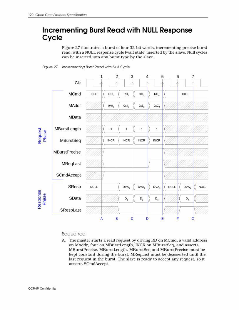
120 Open Core Protocol Specification
Incrementing Burst Read with NULL Response Cycle
Figure 27 illustrates a burst of four 32-bit words, incrementing precise burst read, with a NULL response cycle (wait state) inserted by the slave. Null cycles can be inserted into any burst type by the slave.
Figure 27 Incrementing Burst Read with Null Cycle
SequenceA. The master starts a read request by driving RD on MCmd, a valid address
on MAddr, four on MBurstLength, INCR on MBurstSeq, and asserts MBurstPrecise. MBurstLength, MBurstSeq and MBurstPrecise must be kept constant during the burst. MReqLast must be deasserted until the last request in the burst. The slave is ready to accept any request, so it asserts SCmdAccept.
Clk
MAddr
MCmd
MData
SCmdAccept
SResp
SData
IDLE
0x01
RD1 RD2
0x83 0xC4
RD4
DVA4 NULL
D4
IDLE
DVA1
D1
0x42
RD3
DVA3
D3
NULL
MBurstLength 4 4 44
NULL
Req
uest
Pha
seR
espo
nse
Pha
se
MBurstSeq INCR INCR INCRINCR
MBurstPrecise
MReqLast
SRespLast
C D E
1 2 3 4 5 6 7
DVA2
D2
GFA B
OCP-IP Confidential

Timing Diagrams 121
B. The master issues the next read in the burst. MAddr is set to the next word-aligned address (incremented by 4 in this case). The slave captures the address of the first request and keeps SCmdAccept asserted. The slave responds to the first request by driving DVA on SResp and the read data on SData. The slave must keep SRespLast deasserted until the last response.
C. The master issues the next read in the burst. MAddr is set to the next word-aligned address (incremented by 4 in this case). The master also captures the data for the first read from the slave. The slave captures the address of the second request and keeps SCmdAccept asserted. The slave responds to the second request.
D. The master issues the last request of the burst, incrementing MAddr and asserting MReqLast. The master also captures the data for the second read from the slave. The slave captures the address of the third request and keeps SCmdAccept asserted. The slave responds to the third request.
E. The master captures the data for the third read from the slave. The slave captures the address of the fourth request and keeps SCmdAccept asserted. The slave cannot respond to the fourth request, so it inserts NULL to SResp.
F. The slave responds to the fourth request and asserts SRespLast to indicate the last response of the burst.
G. The master captures the data for the last read from the slave, ending the last response phase.
OCP-IP Confidential
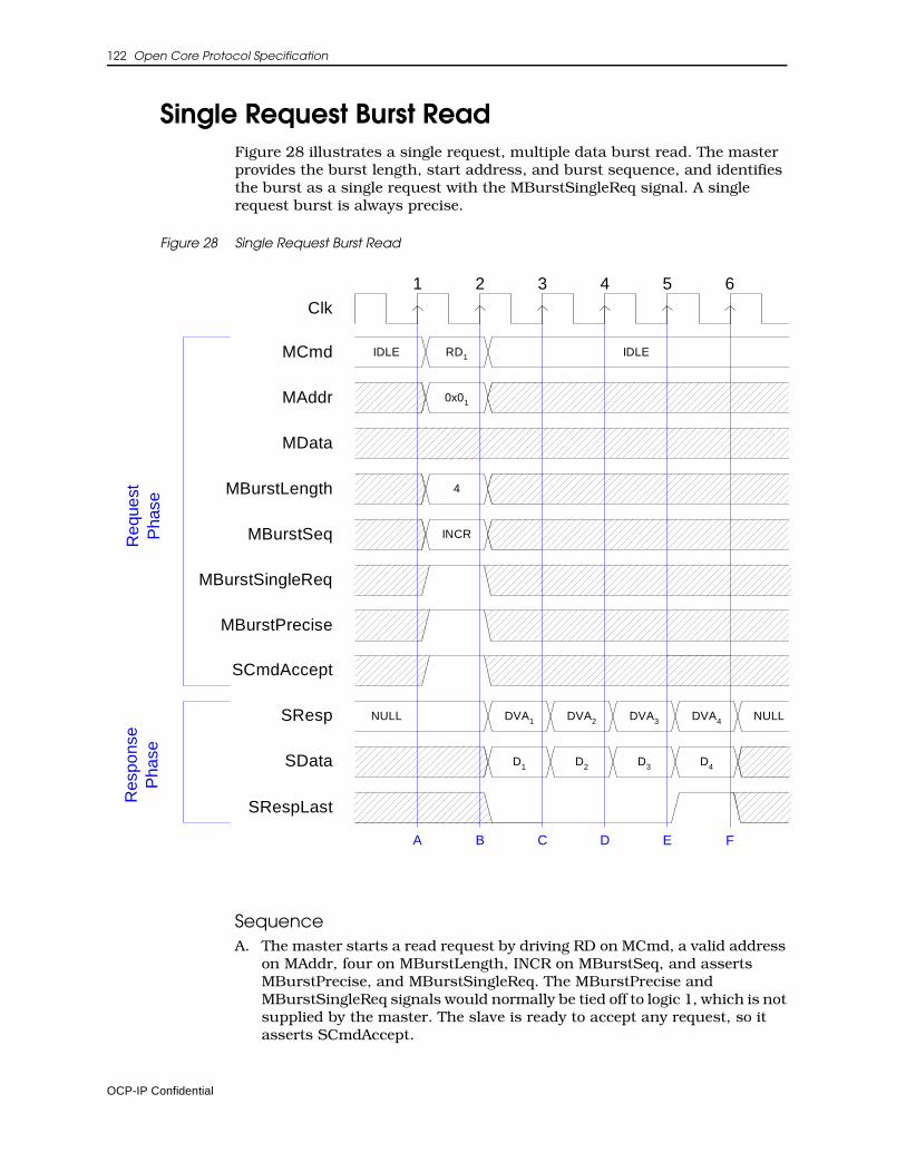
122 Open Core Protocol Specification
Single Request Burst ReadFigure 28 illustrates a single request, multiple data burst read. The master provides the burst length, start address, and burst sequence, and identifies the burst as a single request with the MBurstSingleReq signal. A single request burst is always precise.
Figure 28 Single Request Burst Read
SequenceA. The master starts a read request by driving RD on MCmd, a valid address
on MAddr, four on MBurstLength, INCR on MBurstSeq, and asserts MBurstPrecise, and MBurstSingleReq. The MBurstPrecise and MBurstSingleReq signals would normally be tied off to logic 1, which is not supplied by the master. The slave is ready to accept any request, so it asserts SCmdAccept.
Clk
MAddr
MCmd
MData
SCmdAccept
SResp
SData
IDLE
0x01
RD1
DVA4 NULL
IDLE
DVA1
D1
DVA3
D3
MBurstLength 4
NULL
Req
uest
Pha
seR
espo
nse
Pha
se
MBurstSeq INCR
MBurstSingleReq
MBurstPrecise
SRespLast
1 2 3 4 5 6
DVA2
D2
FC D E
D4
A B
OCP-IP Confidential
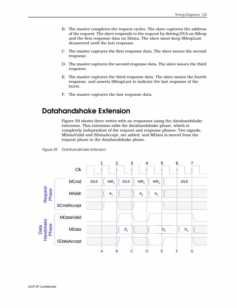
Timing Diagrams 123
B. The master completes the request cycles. The slave captures the address of the request. The slave responds to the request by driving DVA on SResp and the first response data on SData. The slave must keep SRespLast deasserted until the last response.
C. The master captures the first response data. The slave issues the second response.
D. The master captures the second response data. The slave issues the third response.
E. The master captures the third response data. The slave issues the fourth response, and asserts SRespLast to indicate the last response of the burst.
F. The master captures the last response data.
Datahandshake ExtensionFigure 29 shows three writes with no responses using the datahandshake extension. This extension adds the datahandshake phase, which is completely independent of the request and response phases. Two signals, MDataValid and SDataAccept, are added, and MData is moved from the request phase to the datahandshake phase.
Figure 29 Datahandshake Extension
Clk
MAddr
MCmd
MData
SCmdAccept
IDLE
A1
WR1 IDLE
A3
WR3 IDLE
D2
A2
SDataAccept
MDataValid
WR2
D1 D3
Req
uest
Pha
se
2 3 4 5 6 71
A B C D E F G
Dat
aH
ands
hake
Pha
se
OCP-IP Confidential
124 Open Core Protocol Specification
SequenceA. The master starts a write request by driving WR on MCmd and a valid
address on MAddr. It does not yet have the write data, however, so it deasserts MDataValid. The slave asserts SCmdAccept. It does not need to assert or deassert SDataAccept yet, because MDataValid is still deasserted.
B. The slave captures the write address from the master. The master is now ready to transfer the write data, so it asserts MDataValid and drives the data on MData, starting the datahandshake phase. The slave is ready to accept the data immediately, so it asserts SDataAccept. This corresponds to a data accept latency of 0.
C. The master deasserts MDataValid since it has no more data to transfer. (Like MCmd and SResp, MDataValid must always be in a valid, specified state.) The slave captures the write data from MData, completing the transfer. The master starts a second write request by driving WR on MCmd and a valid address on MAddr.
D. Since SCmdAccept is asserted, the master immediately starts a third write request. It also asserts MDataValid and presents the write data of the second write on MData. The slave is not ready for the data yet, so it deasserts SDataAccept.
E. The master sees that SDataAccept is deasserted, so it holds the values of MDataValid and MData. The slave asserts SDataAccept, for a data accept latency of 1.
F. Since SDataAccept is asserted, the datahandshake phase ends. The master is ready to deliver the write data for the third request, so it keeps MDataValid asserted and presents the data on MData. The slave captures the data for the second write from MData, and keeps SDataAccept asserted, for a data accept latency of 0 for the third write.
G. Since SDataAccept is asserted, the datahandshake phase ends. The slave captures the data for the third write from MData.
OCP-IP Confidential
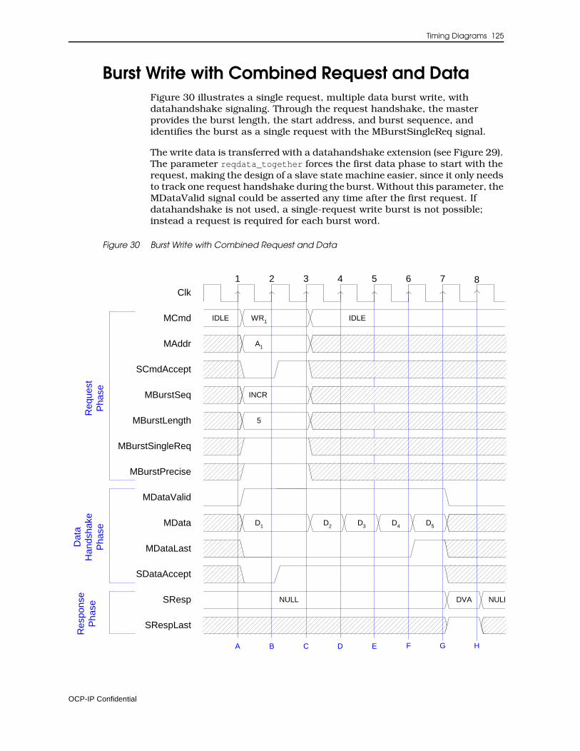
Timing Diagrams 125
Burst Write with Combined Request and DataFigure 30 illustrates a single request, multiple data burst write, with datahandshake signaling. Through the request handshake, the master provides the burst length, the start address, and burst sequence, and identifies the burst as a single request with the MBurstSingleReq signal.
The write data is transferred with a datahandshake extension (see Figure 29). The parameter reqdata_together forces the first data phase to start with the request, making the design of a slave state machine easier, since it only needs to track one request handshake during the burst. Without this parameter, the MDataValid signal could be asserted any time after the first request. If datahandshake is not used, a single-request write burst is not possible; instead a request is required for each burst word.
Figure 30 Burst Write with Combined Request and Data
Clk
MAddr
MCmd
MData
SCmdAccept
IDLE
A1
WR1 IDLE
D2
SDataAccept
MDataValid
D1 D3
Req
uest
Pha
se
2 3 4 5 6 71
Dat
aH
ands
hake
Pha
se
D4 D5
MBurstLength 5
MBurstSingleReq
MBurstPrecise
MBurstSeq INCR
MDataLast
SResp DVA NULLNULL
Res
pons
eP
hase
C E F
8
H
SRespLast
GBA D
OCP-IP Confidential
126 Open Core Protocol Specification
SequenceA. The master starts a write request by driving WR on MCmd, a valid address
on MAddr, INCR on MBurstSeq, five on MBurstLength, and asserts the MBurstPrecise and MBurstSingleReq signals. The master also asserts the MDataValid signal, drives valid data on MData, and deasserts MDataLast. The MDataLast signal must remain deasserted until the last data cycle.
B. Since it has not received SCmdAccept or SDataAccept, the master holds the request phase signals, keeps MDataValid asserted, and MData steady. The slave asserts SCmdAccept and SDataAccept to indicate it is ready to accept the request and the first data phase.
C. The master completes the request phase, asserts MDataValid and drives new data to MData. The slave captures the initial data and keeps SDataAccept asserted to indicate it is ready to accept more data.
D. The master asserts MDataValid and drives new data to MData. The slave captures the second data phase and keeps SDataAccept asserted to indicate it is ready to accept more data.
E. The master asserts MDataValid and drives new data to MData. The slave captures the third data phase and keeps SDataAccept asserted to indicate it is ready to accept more data.
F. The master asserts MDataValid, drives new data to MData, and asserts MDataLast to identify the last data in the burst. The slave captures the fourth data phase and keeps SDataAccept asserted to indicate it is ready to accept more data.
G. The slave captures the last data phase and address.
This example also shows how the slave issues SResp at the end of a burst (when the optional write response is configured in the interface). For single request / multiple data bursts there is only a single response, and it can be issued after the last data has been detected by the slave. The SResp is NULL until point G. in the diagram. The slave may use code DVA to indicate a successful burst, or ERR for an unsuccessful one.
OCP-IP Confidential
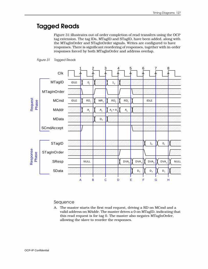
Timing Diagrams 127
Tagged ReadsFigure 31 illustrates out-of-order completion of read transfers using the OCP tag extension. The tag IDs, MTagID and STagID, have been added, along with the MTagInOrder and STagInOrder signals. Writes are configured to have responses. There is significant reordering of responses, together with in-order responses forced by both MTagInOrder and address overlap.
Figure 31 Tagged Reads
SequenceA. The master starts the first read request, driving a RD on MCmd and a
valid address on MAddr. The master drives a 0 on MTagID, indicating that this read request is for tag 0. The master also negates MTagInOrder, allowing the slave to reorder the responses.
Clk
MAddr
MCmd
MData
SCmdAccept
SResp
SData
IDLE
A1
A2
RD1
WR2
IDLE
A3 = A
2
RD3
Req
uest
Pha
seR
espo
nse
Pha
se
A B C D E
MTagID IDLE 01
13
STagID
MTagInOrder
NULL
2 3 4 5 6 71 8
RD4
A4
D2
F G H
STagInOrder
DVA2
NULLDVA4
DVA3
DVA1
0113
D4 D3 D1
OCP-IP Confidential
128 Open Core Protocol Specification
B. Since SCmdAccept is sampled asserted, the request phase ends with a request accept latency of 0. The master begins a write request to a second address, providing the write data on MData. The master asserts MTagInOrder, indicating that the slave may not reorder this request with respect to other in-order transactions and that MTagID is a “don’t care.”
C. When SCmdAccept is sampled asserted, the second request phase ends. The master launches a third request, which is a read to an address that matches the previous write. MTagInOrder is negated, enabling reordering, and the assigned tag value is 1.
D. Since SCmdAccept is sampled asserted, the third request phase ends. The master launches a fourth request, which is a read. MTagInOrder is asserted, forcing ordering with respect to the earlier in-order write. The slave responds to the second request (the in-order write presented at B) by driving DVA on SResp. Since the transaction is in-order, STagInOrder is asserted and STagID is a “don’t care.”
E. SCmdAccept is sampled asserted so the fourth request phase ends. Since the response phase is sampled asserted, the response to the second request ends with a request-to-response latency of 2 cycles. The slave responds to the fourth request (D) by driving DVA on SResp and read data on SData. STagInOrder is asserted to match the associated request. This response was reordered with respect to the first (A) and third (C) requests, which allow reordering.
F. The response phase is sampled asserted so the response to the fourth request ends with a request-to-response latency of 1 cycle. The slave responds to the third request (C) by driving DVA on SResp, read data on SData, and a 1 on STagID. STagInOrder is negated, indicating that reordering is allowed. This response is reordered with respect to the first request (A), but must occur after the second request (B), which has a matching address.
G. Since the response phase is sampled asserted, the response to the third request ends with a request-to-response latency of 3 cycles. The slave responds to the first request (A) by driving DVA on SResp, read data on SData, and a 0 on STagID. STagInOrder is negated.
H. When the response phase is sampled asserted, the response to the first request ends with a request-to-response latency of 6 cycles.
OCP-IP Confidential
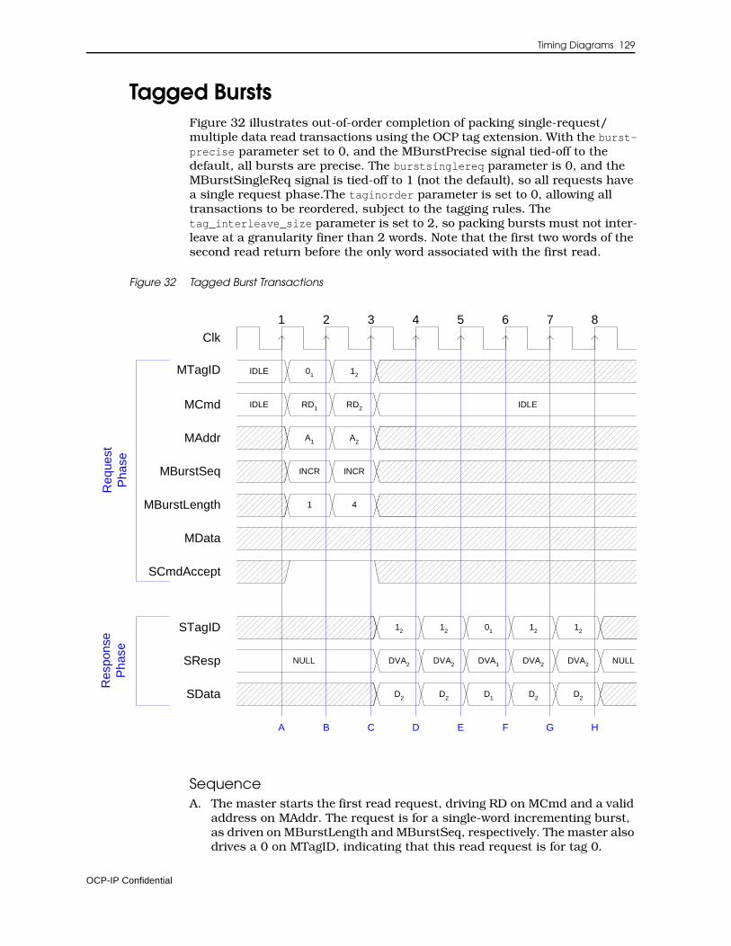
Timing Diagrams 129
Tagged BurstsFigure 32 illustrates out-of-order completion of packing single-request/ multiple data read transactions using the OCP tag extension. With the burst-precise parameter set to 0, and the MBurstPrecise signal tied-off to the default, all bursts are precise. The burstsinglereq parameter is 0, and the MBurstSingleReq signal is tied-off to 1 (not the default), so all requests have a single request phase.The taginorder parameter is set to 0, allowing all transactions to be reordered, subject to the tagging rules. The tag_interleave_size parameter is set to 2, so packing bursts must not inter-leave at a granularity finer than 2 words. Note that the first two words of the second read return before the only word associated with the first read.
Figure 32 Tagged Burst Transactions
SequenceA. The master starts the first read request, driving RD on MCmd and a valid
address on MAddr. The request is for a single-word incrementing burst, as driven on MBurstLength and MBurstSeq, respectively. The master also drives a 0 on MTagID, indicating that this read request is for tag 0.
Clk
MAddr
MCmd
MData
SCmdAccept
SResp
SData
IDLE
A1 A2
RD1 IDLE
Req
uest
Pha
seR
espo
nse
Pha
se
A B C D E
MTagID IDLE 01 12
STagID
NULL
2 3 4 5 6 71 8
RD2
F G H
DVA2 NULLDVA1 DVA2 DVA2
0112
D2 D2 D2
MBurstSeq INCR INCR
MBurstLength 1 4
12 12 12
DVA2
D1D2
OCP-IP Confidential
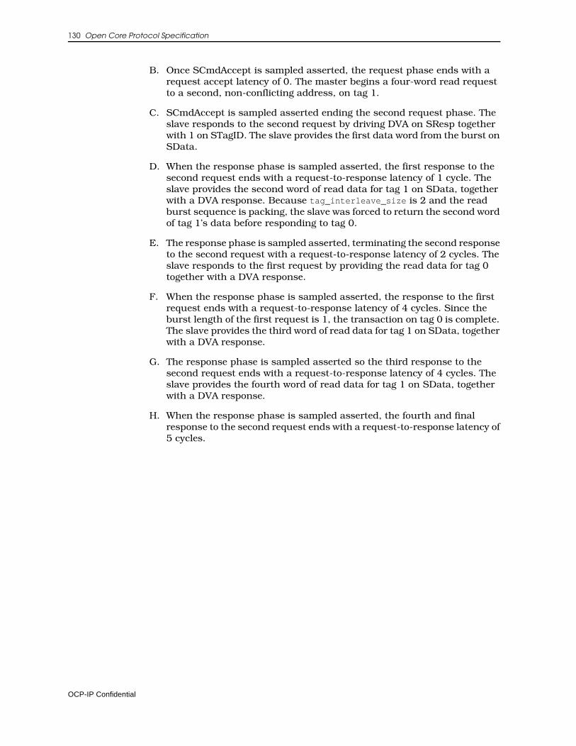
130 Open Core Protocol Specification
B. Once SCmdAccept is sampled asserted, the request phase ends with a request accept latency of 0. The master begins a four-word read request to a second, non-conflicting address, on tag 1.
C. SCmdAccept is sampled asserted ending the second request phase. The slave responds to the second request by driving DVA on SResp together with 1 on STagID. The slave provides the first data word from the burst on SData.
D. When the response phase is sampled asserted, the first response to the second request ends with a request-to-response latency of 1 cycle. The slave provides the second word of read data for tag 1 on SData, together with a DVA response. Because tag_interleave_size is 2 and the read burst sequence is packing, the slave was forced to return the second word of tag 1’s data before responding to tag 0.
E. The response phase is sampled asserted, terminating the second response to the second request with a request-to-response latency of 2 cycles. The slave responds to the first request by providing the read data for tag 0 together with a DVA response.
F. When the response phase is sampled asserted, the response to the first request ends with a request-to-response latency of 4 cycles. Since the burst length of the first request is 1, the transaction on tag 0 is complete. The slave provides the third word of read data for tag 1 on SData, together with a DVA response.
G. The response phase is sampled asserted so the third response to the second request ends with a request-to-response latency of 4 cycles. The slave provides the fourth word of read data for tag 1 on SData, together with a DVA response.
H. When the response phase is sampled asserted, the fourth and final response to the second request ends with a request-to-response latency of 5 cycles.
OCP-IP Confidential
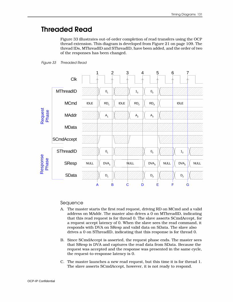
Timing Diagrams 131
Threaded ReadFigure 33 illustrates out-of-order completion of read transfers using the OCP thread extension. This diagram is developed from Figure 21 on page 109. The thread IDs, MThreadID and SThreadID, have been added, and the order of two of the responses has been changed.
Figure 33 Threaded Read
SequenceA. The master starts the first read request, driving RD on MCmd and a valid
address on MAddr. The master also drives a 0 on MThreadID, indicating that this read request is for thread 0. The slave asserts SCmdAccept, for a request accept latency of 0. When the slave sees the read command, it responds with DVA on SResp and valid data on SData. The slave also drives a 0 on SThreadID, indicating that this response is for thread 0.
B. Since SCmdAccept is asserted, the request phase ends. The master sees that SResp is DVA and captures the read data from SData. Because the request was accepted and the response was presented in the same cycle, the request-to-response latency is 0.
C. The master launches a new read request, but this time it is for thread 1. The slave asserts SCmdAccept, however, it is not ready to respond.
Clk
MAddr
MCmd
MData
SCmdAccept
SResp
SData
IDLE
NULL
A1
RD1 IDLE
NULL
A3
RD3
DVA2 NULL
D2
IDLE
DVA1
D1
A2
RD2
DVA3
D3
NULL
MThreadID 01 0312
SThreadID 1201 03
A B C D E F G
2 3 4 5 6 71
Req
uest
Pha
seR
espo
nse
Pha
se
OCP-IP Confidential

132 Open Core Protocol Specification
D. Since SCmdAccept is asserted, the master can launch another read request. This request is for thread 0, so MThreadID is switched back to 0. The slave captures the address of the second read for thread 1, but it begins driving DVA on SResp, data on SData, and a 0 on SThreadID. This means that it is responding to the third read, before the second read.
E. Since SCmdAccept is asserted, the third request ends. The master sees that the slave has produced a valid response to the third read and captures the data from SData. The request-to-response latency for this transfer is 0.
F. The slave has the data for the second read, so it drives DVA on SResp, data on SData, and a 1 on SThreadID.
G. The master captures the data for the second read from SData. The request-to-response latency for this transfer is 3.
OCP-IP Confidential
Timing Diagrams 133
Threaded Read with Thread BusyFigure 34 illustrates the out-of-order completion of read transfers using the OCP thread extension. The change to Figure 33 is the addition of thread busy signals. In this example, the thread busy is only a hint, since the sthreadbusy_exact parameter is not set. In this case the master may ignore the SThreadBusy signals, and the slave does not have to accept requests even when it is not busy.
When thread busy is treated as a hint and a request or thread is not accepted, the interface may block for all threads. Blocking of this type can be avoided by treating thread busy as an exact signal using the sthreadbusy_exact parameter. For an example, see “Threaded Read with Thread Busy Exact”.
This example shows only the request part of the read transfers. The response part can use a similar mechanism for thread busy.
Figure 34 Threaded Read with Thread Busy
SequenceA. The master starts the first read request, driving RD on MCmd and a valid
address on MAddr. The master also drives a 0 on MThreadID, associating this read request with thread 0. The slave asserts SCmdAccept for a request accept latency of 0.
B. Since SCmdAccept is asserted, the request phase ends.
Clk
MAddr
MCmd
MData
SCmdAccept
IDLE
A1
RD1 IDLE IDLE
A2
RD2
MThreadID 01 12
A B
2 3 4 5 61
Req
uest
Pha
se
SThreadBusy[1]
SThreadBusy[0]
A3
RD3
02
7
GC D FE
OCP-IP Confidential
134 Open Core Protocol Specification
C. The slave asserts SThreadBusy[1] since it is not ready to accept requests on thread 1. The master ignores the hint, and launches a new read request for thread 1. The master can issue a request even though the slave asserts SThreadbusy (see transfer 2). All threads are now blocked.
D. The slave deasserts SThreadBusy[1] and asserts SCmdAccept to complete the request for thread 1.
E. Since SCmdAccept is asserted, the second request ends. The master issues a new request to thread 0. The slave is not ready to accept the request, and indicates this condition by keeping SCmdAccept deasserted. It chooses not to assert SThreadBusy[0]. The slave does not have to assert SCmdAccept for a request, even if it did not assert SThreadbusy (see transfer 3).
F. The slave asserts the SCmdAccept to complete the request on thread 0.
G. The master captures the SCmdAccept to complete the requests.
OCP-IP Confidential
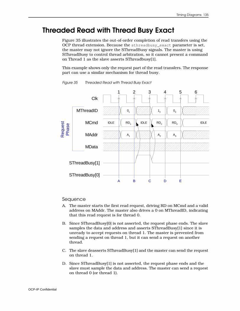
Timing Diagrams 135
Threaded Read with Thread Busy ExactFigure 35 illustrates the out-of-order completion of read transfers using the OCP thread extension. Because the sthreadbusy_exact parameter is set, the master may not ignore the SThreadBusy signals. The master is using SThreadBusy to control thread arbitration, so it cannot present a command on Thread 1 as the slave asserts SThreadbusy[1].
This example shows only the request part of the read transfers. The response part can use a similar mechanism for thread busy.
Figure 35 Threaded Read with Thread Busy Exact
SequenceA. The master starts the first read request, driving RD on MCmd and a valid
address on MAddr. The master also drives a 0 on MThreadID, indicating that this read request is for thread 0.
B. Since SThreadBusy[0] is not asserted, the request phase ends. The slave samples the data and address and asserts SThreadBusy[1] since it is unready to accept requests on thread 1. The master is prevented from sending a request on thread 1, but it can send a request on another thread.
C. The slave deasserts SThreadBusy[1] and the master can send the request on thread 1.
D. Since SThreadBusy[1] is not asserted, the request phase ends and the slave must sample the data and address. The master can send a request on thread 0 (or thread 1).
Clk
MAddr
MCmd
MData
IDLE
A1
RD1 IDLE
A3
RD3 IDLE
A2
RD2
MThreadID 01 0312
A B D E
2 3 4 5 61
Req
uest
Pha
se
SThreadBusy[1]
SThreadBusy[0]C
OCP-IP Confidential
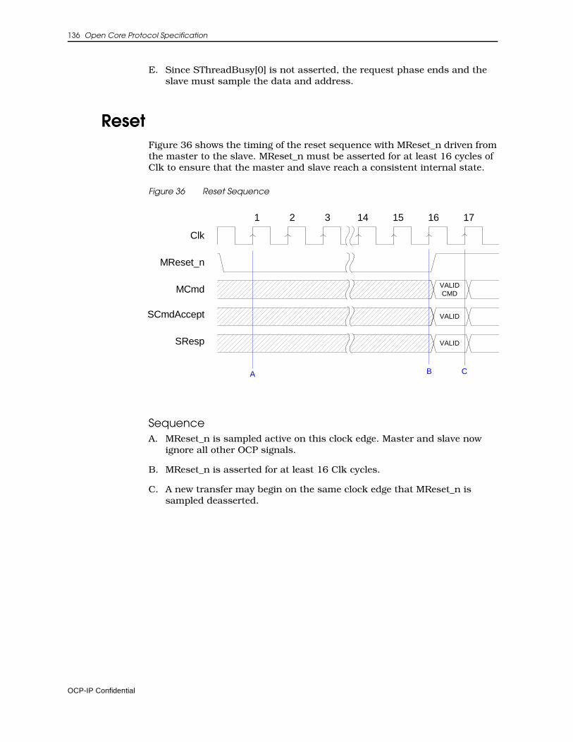
136 Open Core Protocol Specification
E. Since SThreadBusy[0] is not asserted, the request phase ends and the slave must sample the data and address.
ResetFigure 36 shows the timing of the reset sequence with MReset_n driven from the master to the slave. MReset_n must be asserted for at least 16 cycles of Clk to ensure that the master and slave reach a consistent internal state.
Figure 36 Reset Sequence
SequenceA. MReset_n is sampled active on this clock edge. Master and slave now
ignore all other OCP signals.
B. MReset_n is asserted for at least 16 Clk cycles.
C. A new transfer may begin on the same clock edge that MReset_n is sampled deasserted.
VALID
MCmd
SCmdAccept
SResp
BA
MReset_n
Clk
2 3 15 161
VALID
14
VALID CMD
C
17
OCP-IP Confidential
9 Developers Guidelines
This chapter collects examples and implementation tips that can help you make effective use of the Open Core Protocol and does not provide any addi-tional specification material. This chapter groups together a variety of topics including discussions of:
1. The basic OCP with an emphasis on signal timing, state machines and OCP subsets.
2. Simple extensions that cover byte enables, multiple address spaces and in-band information
3. An overview of the new 2.0 burst capabilities
4. The concepts of threading and connections
5. OCP features addressing the new write semantics, synchronization issues, and endianness
6. Sideband signals with an emphasis on reset management
7. A description of the debug and test interface
Basic OCPThis section considers the different OCP phases, their relationships, and identifies sensitive timing-related areas. The section includes descriptions of OCP compliant state machines, and also discusses the OCP parameters needed to define simple OCP interfaces.
OCP-IP Confidential
138 Open Core Protocol Specification
Signal TimingThe Open Core Protocol data transfer model allows many different types of existing legacy IP cores to be bridged to the OCP without adding expensive glue logic structures that include address or data storage. As such, it is possible to draw many state machine diagrams that are compliant with the OCP protocol. This section describes some common state machine models that can be used with the OCP, together with guidance on the use of those models.
Two-way handshaking is the general principle of the dataflow signals in the OCP interface. A group of signals is asserted and must be held steady until the corresponding accept signal is asserted. This allows the receiver of a signal to force the sender to hold the signals steady until it has completely processed them. This principle produces implementations with fewer latches for temporary storage.
OCP principles are built around three fundamental decoupled phases: the request phase, the response phase, and the datahandshake phase.
Request PhaseRequest flow control relies on standard request/accept handshaking signals: MCmd and SCmdAccept. Note that in version 2.0 of this specification, SCmdAccept becomes an optional signal, enabled by the cmdaccept param-eter. When the signal is not physically present on the interface, it naturally defaults to 1, meaning that a request phase in that case lasts exactly one clock cycle.
The request phase begins when the master drives MCmd to a value other than Idle. When MCmd != Idle, MCmd is referred to as asserted. All of the other request phase outputs of the master must become valid during the same clock cycle as MCmd asserted, and be held steady until the request phase ends. The request phase ends when SCmdAccept is sampled asserted (true) by the rising edge of Clk. The slave can assert SCmdAccept in the same cycle that MCmd is asserted, or stay negated for several Clk cycles. The latter choice allows the slave to force the master to hold its request phase outputs until the slave can accomplish its access without latching address or data signals.
The slave designer chooses the delay between MCmd asserted and SCmdAc-cept asserted based on the desired area, timing, and throughput characteristics of the slave.
As the request phase does not begin until MCmd is asserted, SCmdAccept is a “don’t care” while MCmd is not asserted so SCmdAccept can be asserted before MCmd. This allows some area-sensitive, low frequency slaves to tie SCmdAccept asserted, as long as they can always complete their transfer responsibilities in the same cycle that MCmd is asserted. Since an MCmd value of Idle specifies the absence of a valid command, the master can assert MCmd independently of the current setting of SCmdAccept.
The highest throughput that can be achieved with the OCP is one data transfer per Clk cycle. High-throughput slaves can approach this rate by providing sufficient internal resources to end most request phases in the same Clk cycle that they start. This implies a combinational path from the
OCP-IP Confidential
Developers Guidelines 139
master’s MCmd output into slave logic, then back out the slaves SCmdAccept output and back into a state machine in the master. If the master has addi-tional requests to present, it can start a new request phase on the next Clk cycle. Achieving such high throughput in high-frequency systems requires careful design including cycle time budgeting as described in “Level2 Timing” on page 172.
Response PhaseThe response phase begins when the slave drives SResp to a value other than NULL. When SResp != NULL, SResp is referred to as asserted. All of the other response phase outputs of the slave must become valid during the same Clk cycle as SResp asserted, and be held steady until the response phase ends. The response phase ends when MRespAccept is sampled asserted (true) by the rising edge of Clk; if MRespAccept is not configured into a particular OCP, MRespAccept is assumed to be always asserted (that is, the response phase always ends in the same cycle it begins). If present, the master can assert MRespAccept in the same cycle that MResp is asserted, or it may stay negated for several Clk cycles. The latter choice allows the master to force the slave to hold its response phase outputs so the master can finish the transfer without latching the data signals.
Since the response phase does not begin until SResp is asserted, MRespAc-cept is a “don’t care” while SResp is not asserted so MRespAccept can be asserted before SResp. Since an SResp value of NULL specifies the absence of a valid response, the slave can assert SResp independently of the current setting of MRespAccept.
In high-throughput systems, careful use of MRespAccept can result in signif-icant area savings. To maintain high throughput, systems traditionally introduce pipelining, where later requests begin before earlier requests have finished. Pipelining is particularly important to optimize Read accesses to main memory.
The OCP supports pipelining with its basic request/response protocol, since a master is free to start the second request phase as soon as the first has finished (before the first response phase, in many cases). However, without MRespAccept, the master must have sufficient storage resources to receive all of the data it has requested. This is not an issue for some masters, but can be expensive when the master is part of a bridge between subsystems such as computer buses. While the original system initiator may have enough storage, the intermediate bridge may not. If the slave has storage resources (or the ability to flow control data that it is requesting), then allowing the master to de-assert MRespAccept enables the system to operate at high throughput without duplicating worst-case storage requirements across the die.
If a target core natively includes buffering resources that can be used for response flow control at little cost, using MRespAccept can reduce the response buffering requirement in a complex SOC interconnect.
Most simple or low-throughput slave IP cores need not implement MRespAc-cept. Misuse of MRespAccept makes the slave’s job more difficult, because it adds extra conditions (and states) to the slave’s logic.
OCP-IP Confidential
140 Open Core Protocol Specification
Datahandshake PhaseThe datahandshake extension allows the de-coupling of a write address from write data. The extension is typically only useful for master and slave devices that require the throughput advantages available through transfer pipelining (particularly memory). When the datahandshake phase is not present in a configured OCP, MData becomes a request phase signal.
The datahandshake phase begins when the master asserts MDataValid. The other datahandshake phase outputs of the master must become valid during the same Clk cycle while MDataValid is asserted, and be held steady until the datahandshake phase ends. The datahandshake phase ends when SDataAc-cept is sampled asserted (true) by the rising edge of Clk. The slave can assert SDataAccept in the same cycle that MDataValid is asserted, or it can stay negated for several Clk cycles. The latter choice allows the slave to force the master to hold its datahandshake phase outputs so the slave can accomplish its access without latching data signals.
The datahandshake phase does not begin until MDataValid is asserted. While MDataValid is not asserted, SDataAccept is a “don’t care”. SDataAccept can be asserted before MDataValid. Since MDataValid not being asserted specifies the absence of valid data, the master can assert MDataValid independently of the current setting of SDataAccept.
State Machine ExamplesThe sample state machine implementations in this section use only the features of the basic OCP, request and response phases (the datahandshake phase is not discussed here but can be derived). The examples highlight the flexibility of the basic OCP.
Sequential MasterThe first example is a medium-throughput, high-frequency master design. To achieve high frequency, the implementation is a completely sequential (that is, Moore state machine) design. Figure 37 shows the state machine associ-ated with the master’s OCP.
OCP-IP Confidential
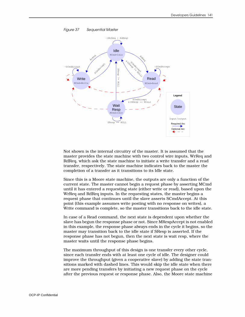
Developers Guidelines 141
Figure 37 Sequential Master
Not shown is the internal circuitry of the master. It is assumed that the master provides the state machine with two control wire inputs, WrReq and RdReq, which ask the state machine to initiate a write transfer and a read transfer, respectively. The state machine indicates back to the master the completion of a transfer as it transitions to its Idle state.
Since this is a Moore state machine, the outputs are only a function of the current state. The master cannot begin a request phase by asserting MCmd until it has entered a requesting state (either write or read), based upon the WrReq and RdReq inputs. In the requesting states, the master begins a request phase that continues until the slave asserts SCmdAccept. At this point (this example assumes write posting with no response on writes), a Write command is complete, so the master transitions back to the idle state.
In case of a Read command, the next state is dependent upon whether the slave has begun the response phase or not. Since MRespAccept is not enabled in this example, the response phase always ends in the cycle it begins, so the master may transition back to the idle state if SResp is asserted. If the response phase has not begun, then the next state is wait resp, where the master waits until the response phase begins.
The maximum throughput of this design is one transfer every other cycle, since each transfer ends with at least one cycle of idle. The designer could improve the throughput (given a cooperative slave) by adding the state tran-sitions marked with dashed lines. This would skip the idle state when there are more pending transfers by initiating a new request phase on the cycle after the previous request or response phase. Also, the Moore state machine
Idle
Write Read
MCmd=Idle
MCmd=Write MCmd=Read
Legend:
State
Input/output
Required Arc
Optional Arc
SResp == NULL
~SCmdAccept ~SCmdAccept
~(WrReq | RdReq)
WrReq RdReq
SCmdAccept
SCmdAccept
SResp != NULL
&(SResp != NULL)
SCmdAccept&(SResp == NULL)
WaitResp
MCmd=Idle
OCP-IP Confidential
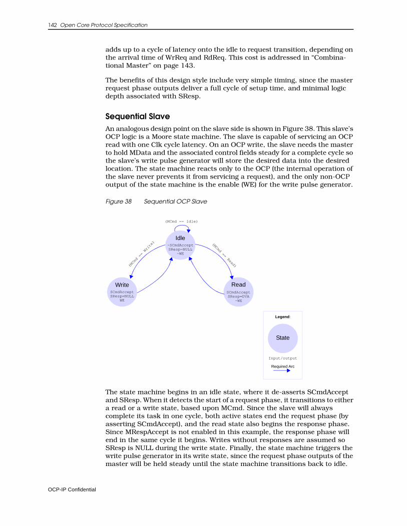
142 Open Core Protocol Specification
adds up to a cycle of latency onto the idle to request transition, depending on the arrival time of WrReq and RdReq. This cost is addressed in “Combina-tional Master” on page 143.
The benefits of this design style include very simple timing, since the master request phase outputs deliver a full cycle of setup time, and minimal logic depth associated with SResp.
Sequential SlaveAn analogous design point on the slave side is shown in Figure 38. This slave’s OCP logic is a Moore state machine. The slave is capable of servicing an OCP read with one Clk cycle latency. On an OCP write, the slave needs the master to hold MData and the associated control fields steady for a complete cycle so the slave’s write pulse generator will store the desired data into the desired location. The state machine reacts only to the OCP (the internal operation of the slave never prevents it from servicing a request), and the only non-OCP output of the state machine is the enable (WE) for the write pulse generator.
Figure 38 Sequential OCP Slave
The state machine begins in an idle state, where it de-asserts SCmdAccept and SResp. When it detects the start of a request phase, it transitions to either a read or a write state, based upon MCmd. Since the slave will always complete its task in one cycle, both active states end the request phase (by asserting SCmdAccept), and the read state also begins the response phase. Since MRespAccept is not enabled in this example, the response phase will end in the same cycle it begins. Writes without responses are assumed so SResp is NULL during the write state. Finally, the state machine triggers the write pulse generator in its write state, since the request phase outputs of the master will be held steady until the state machine transitions back to idle.
Write ReadSCmdAccept SCmdAccept
Legend:
State
Input/output
Required Arc
(MCmd == Idle)
(MCmd == Write) (MCmd == Read)
SResp=NULLWE
SResp=DVA~WE
Idle~SCmdAcceptSResp=NULL
~WE
OCP-IP Confidential
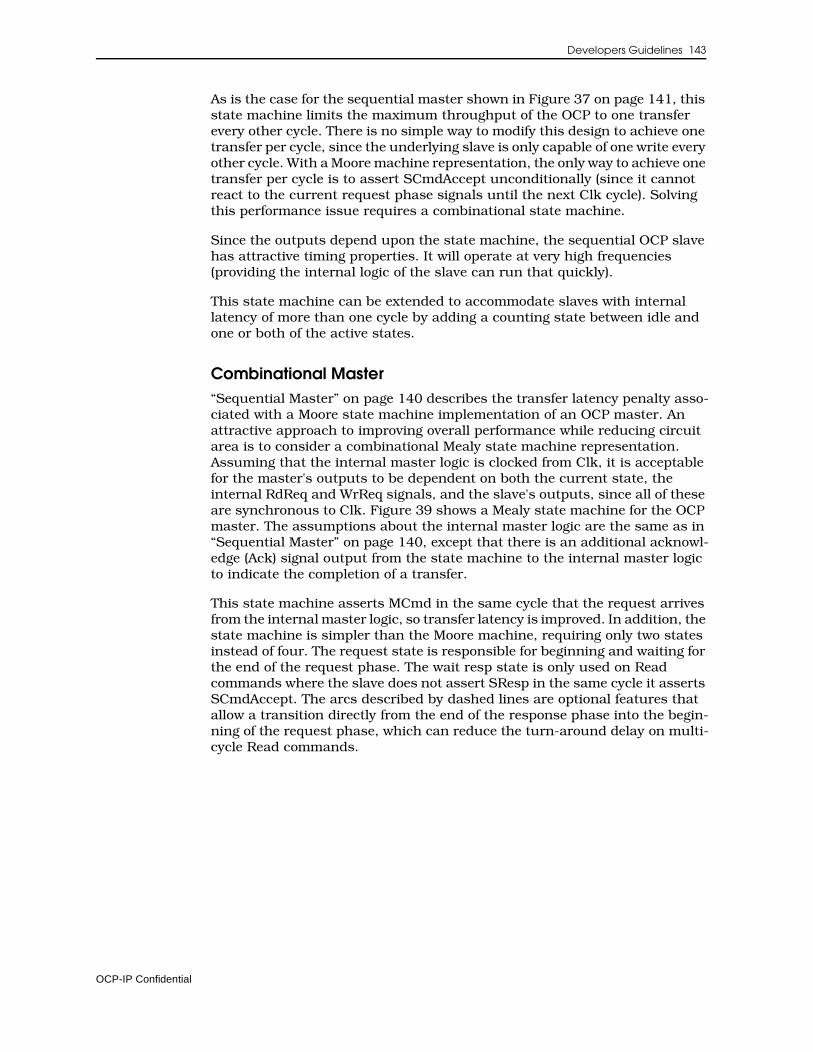
Developers Guidelines 143
As is the case for the sequential master shown in Figure 37 on page 141, this state machine limits the maximum throughput of the OCP to one transfer every other cycle. There is no simple way to modify this design to achieve one transfer per cycle, since the underlying slave is only capable of one write every other cycle. With a Moore machine representation, the only way to achieve one transfer per cycle is to assert SCmdAccept unconditionally (since it cannot react to the current request phase signals until the next Clk cycle). Solving this performance issue requires a combinational state machine.
Since the outputs depend upon the state machine, the sequential OCP slave has attractive timing properties. It will operate at very high frequencies (providing the internal logic of the slave can run that quickly).
This state machine can be extended to accommodate slaves with internal latency of more than one cycle by adding a counting state between idle and one or both of the active states.
Combinational Master“Sequential Master” on page 140 describes the transfer latency penalty asso-ciated with a Moore state machine implementation of an OCP master. An attractive approach to improving overall performance while reducing circuit area is to consider a combinational Mealy state machine representation. Assuming that the internal master logic is clocked from Clk, it is acceptable for the master's outputs to be dependent on both the current state, the internal RdReq and WrReq signals, and the slave's outputs, since all of these are synchronous to Clk. Figure 39 shows a Mealy state machine for the OCP master. The assumptions about the internal master logic are the same as in “Sequential Master” on page 140, except that there is an additional acknowl-edge (Ack) signal output from the state machine to the internal master logic to indicate the completion of a transfer.
This state machine asserts MCmd in the same cycle that the request arrives from the internal master logic, so transfer latency is improved. In addition, the state machine is simpler than the Moore machine, requiring only two states instead of four. The request state is responsible for beginning and waiting for the end of the request phase. The wait resp state is only used on Read commands where the slave does not assert SResp in the same cycle it asserts SCmdAccept. The arcs described by dashed lines are optional features that allow a transition directly from the end of the response phase into the begin-ning of the request phase, which can reduce the turn-around delay on multi-cycle Read commands.
OCP-IP Confidential
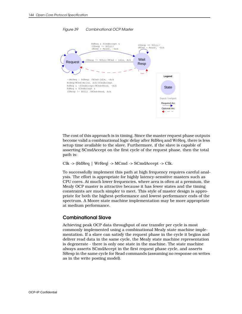
144 Open Core Protocol Specification
Figure 39 Combinational OCP Master
The cost of this approach is in timing. Since the master request phase outputs become valid a combinational logic delay after RdReq and WrReq, there is less setup time available to the slave. Furthermore, if the slave is capable of asserting SCmdAccept on the first cycle of the request phase, then the total path is:
Clk -> (RdReq | WrReq) -> MCmd -> SCmdAccept -> Clk.
To successfully implement this path at high frequency requires careful anal-ysis. The effort is appropriate for highly latency-sensitive masters such as CPU cores. At much lower frequencies, where area is often at a premium, the Mealy OCP master is attractive because it has fewer states and the timing constraints are much simpler to meet. This style of master design is appro-priate for both the highest-performance and lowest-performance ends of the spectrum. A Moore state machine implementation may be more appropriate at medium performance.
Combinational SlaveAchieving peak OCP data throughput of one transfer per cycle is most commonly implemented using a combinational Mealy state machine imple-mentation. If a slave can satisfy the request phase in the cycle it begins and deliver read data in the same cycle, the Mealy state machine representation is degenerate - there is only one state in the machine. The state machine always asserts SCmdAccept in the first request phase cycle, and asserts SResp in the same cycle for Read commands (assuming no response on writes as in the write posting model).
RequestWait
Legend:
State
Input/output
Required Arc
Optional Arc
RdReq & SCmdAccept &
Resp(SResp != NULL)/MCmd = Idle, Ack
(SResp == NULL)/(MCmd = Read), ~Ack
(SResp == NULL)/(MCmd = Read), ~Ack
~(WrReq | RdReq) /MCmd=Idle, ~Ack
WrReq/MCmd=Write, Ack=SCmdAcceptRdReq & ~SCmdAccept/MCmd=Read, ~AckRdReq & SCmdAccept &(SResp != NULL) /MCmd=Read, Ack
OCP-IP Confidential
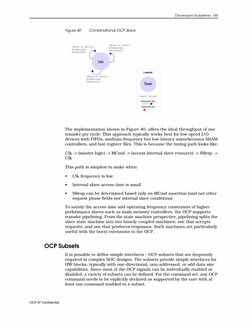
Developers Guidelines 145
Figure 40 Combinational OCP Slave
The implementation shown in Figure 40, offers the ideal throughput of one transfer per cycle. This approach typically works best for low-speed I/O devices with FIFOs, medium-frequency but low-latency asynchronous SRAM controllers, and fast register files. This is because the timing path looks like:
Clk -> (master logic) -> MCmd -> (access internal slave resource) -> SResp -> Clk
This path is simplest to make when:
• Clk frequency is low
• Internal slave access time is small
• SResp can be determined based only on MCmd assertion (and not other request phase fields nor internal slave conditions)
To satisfy the access time and operating frequency constraints of higher-performance slaves such as main memory controllers, the OCP supports transfer pipelining. From the state machine perspective, pipelining splits the slave state machine into two loosely-coupled machines: one that accepts requests, and one that produces responses. Such machines are particularly useful with the burst extensions to the OCP.
OCP SubsetsIt is possible to define simple interfaces - OCP subsets that are frequently required in complex SOC designs. The subsets provide simple interfaces for HW blocks, typically with one-directional, non-addressed, or odd data size capabilities. Since most of the OCP signals can be individually enabled or disabled, a variety of subsets can be defined. For the command set, any OCP command needs to be explicitly declared as supported by the core with at least one command enabled in a subset.
Legend:
State
Input/output
Required Arc
Optional Arc
(MCmd == Write)/SCmdAccept,SResp=NULL
Idle
(MCmd == Idle)/SCmdAccept,SResp=NULL
(MCmd == Read)/SCmdAccept,SResp=DVA
OCP-IP Confidential
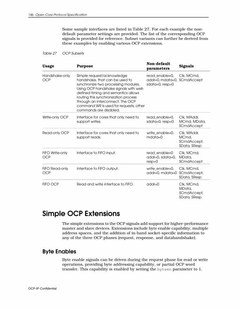
146 Open Core Protocol Specification
Some sample interfaces are listed in Table 27. For each example the non-default parameter settings are provided. The list of the corresponding OCP signals is provided for reference. Subset variants can further be derived from these examples by enabling various OCP extensions.
Table 27 OCP Subsets
Simple OCP ExtensionsThe simple extensions to the OCP signals add support for higher-performance master and slave devices. Extensions include byte enable capability, multiple address spaces, and the addition of in-band socket-specific information to any of the three OCP phases (request, response, and datahandshake).
Byte EnablesByte enable signals can be driven during the request phase for read or write operations, providing byte addressing capability, or partial OCP word transfer. This capability is enabled by setting the byteen parameter to 1.
Usage PurposeNon-default parameters
Signals
Handshake-only OCP
Simple request/acknowledge handshake, that can be used to synchronize two processing modules. Using OCP handshake signals with well-defined timing and semantics allows routing this synchronization process through an interconnect. The OCP command WR is used for requests, other commands are disabled.
read_enable=0, addr=0, mdata=0, sdata=0, resp=0
Clk, MCmd, SCmdAccept
Write-only OCP Interface for cores that only need to support writes.
read_enable=0, sdata=0, resp=0
Clk, MAddr, MCmd, MData, SCmdAccept
Read-only OCP Interface for cores that only need to support reads.
write_enable=0, mdata=0
Clk, MAddr, MCmd, SCmdAccept, SData, SResp
FIFO Write-only OCP
Interface to FIFO input. read_enable=0 addr=0, sdata=0, resp=0
Clk, MCmd, MData, SCmdAccept
FIFO Read-only OCP
Interface to FIFO output. write_enable=0, addr=0, mdata=0
Clk, MCmd, SCmdAccept, SData, SResp
FIFO OCP Read and write interface to FIFO. addr=0 Clk, MCmd, MData, SCmdAccept, SData, SResp
OCP-IP Confidential
Developers Guidelines 147
Even for simpler OCP cores, it is good practice to implement the byte enable extension, making byte addressing available at the chip level with no restric-tions for the host processors.
When a datahandshake phase is used (typically for a single request-multiple data burst), bursts must have the same byte enable pattern on all write data words. It is often necessary to send or receive write byte enables with the write data. To provide full byte addressing capability, the MDataByteEn field can be added to the datahandshake phase. This field indicates which bytes within the OCP data write word are part of the current write transfer.
For example, on its master OCP port, a 2D-graphics accelerator can use vari-able byte enable patterns to achieve good transparent block transfer performance. Any pixel during the memory copy operation that matches the color key value is discarded in the write by de-asserting the corresponding byte enable in the OCP word. Another example is a DRAM controller that, when connected to a x16-DDR device, needs to use the memory data mask lines to perform byte or 16-bit writes. The data mask lines are directly derived from the byte enable pattern.
Unpacking operations inside an interconnect can generate variable byte enable patterns across a burst on the narrower OCP side, even if the pattern is constant on the wider OCP side. Such unpacking operations may also result in a byte enable pattern of all zeros. Therefore, it is mandatory that slave cores fully support 0 as a legal pattern.
An OCP interface can be configured to include partial word transfers by using either the MByteEn field, or the MDataByteEn field, or both.
• If only MByteEn is present, the partial word is specified by this field for both read and write type transfers as part of the request phase. This is the most common case.
• If only MDataByteEn is present, the partial word is specified by this field for write type transfers as part of the datahandshake phase, and partial word reads are not supported.
• If both MByteEn and MDataByteEn are present, MByteEn specifies partial words for read transfers as part of the request phase, and is don’t care for write type transfers. MDataByteEn specifies partial words for write transfers as part of the datahandshake phase, and is don’t care for read type transfers.
Multiple Address SpacesLogically separate memory regions with unique properties or behavior are often scattered in the system address map. The MAddrSpace signal permits explicit selection of these separate address spaces.
Address spaces typically differentiate a memory space within a core from the configuration register space within that same core, or differentiate several cores into an OCP subsystem including multiple OCP cores that can be mapped at non-contiguous addresses, from the top level system perspective.
OCP-IP Confidential
148 Open Core Protocol Specification
Another example of the usage of the addrspace extension is the case of an OCP-to-PCI bridge, since PCI natively supports address spaces for configura-tion registers, memory spaces and i/o spaces.
In-Band InformationOCP can be extended to communicate information that is not assigned semantics by the OCP protocol. This is true for out-of-band information (flag, control/status signals) and also for in-band information. The designer or the chip level architect can define in-band extensions for the OCP phases.
The fields provided for that purpose are MReqInfo for the request phase, SRespInfo for the response phase, MDataInfo for the request phase or the datahandshake phase, and SDataInfo for the response phase. The presence and width of these fields can be controlled individually.
MReqInfoUses for MReqInfo can include user/supervisor storage attributes, cacheable storage attributes, data versus program access, emulation versus application access or any other access-related information, such as dynamic endianness qualification or access permission information.
MReqInfo bits have no assigned meanings but have behavior restrictions. MReqInfo is part of the request phase, so when MCmd is Idle, MReqInfo is a "don’t care". When MCmd is asserted, MReqInfo must be held steady for the entire request phase. MReqInfo must be constant across an entire transac-tion, so the value may not change during a burst. This facilitates simple packing and unpacking of data at mismatched master/slave data widths, eliminating the transformation of information.
SRespInfoUses for SRespInfo can include error or status information, such as FIFO full or empty indications, or data response endianness information.
SRespInfo bits have no assigned meaning, but have behavior restrictions. SRespInfo is part of the response phase, so when SResp is NULL, SRespInfo is a "don’t care". When SResp is asserted, SRespInfo must be held steady for the entire response phase. Whenever possible, slaves that generate SRespInfo values should hold them constant for the duration of the transaction, and choose semantics that favor sticky status bits that stay asserted across trans-actions. This simplifies the design of interconnects and bridges that span OCP interfaces with different configurations. Holding SRespInfo constant improves simple packing and unpacking of data at mismatched data widths. The span-ning element may need to break a single transaction into multiple smaller transactions, and so manage the combination of multiple SRespInfo values when the original transaction has fewer responses than the converted ones.
If you implement SRespInfo as specified, your implementation should work in future versions of the specification. If the current implementation does not meet your needs, please contact [email protected] so that the Specifica-tion Working Group can investigate how to satisfy your requirements.
OCP-IP Confidential
Developers Guidelines 149
MDataInfo and SDataInfoMDataInfo and SDataInfo have slightly different semantics. While they have no OCP-defined meaning, they may have packing/unpacking implications. MDataInfo and SDataInfo are only valid when their associated phase is asserted (request or datahandshake phase for MDataInfo, response phase for SDataInfo).
Uses for the MDataInfo and SDataInfo fields might include byte data parity in the low-order bits and/or data ECC values in the high-order (non-packable) bits.
The low-order mdatainfobyte_wdth bits of MDataInfo are associated with MData[7:0], and so forth for each higher-numbered byte within MData, so that the low-order mdatainfobyte_wdth*(data_wdth/8) bits of MDataInfo are associated with individual data bytes. Any remaining (upper) bits of MDataInfo cannot be packed or unpacked without further specification, although such bits may be used in cases with matched data width, where no transformation is required.
The difference between MReqInfo and the upper bits of MDataInfo is that only MDataInfo is allowed to change during a transaction. Use SDataInfo for infor-mation that may change during a transaction.
A slave should be operable when all bits of MReqInfo and MDataInfo are negated; in other words, any MReqInfo or MDataInfo signals defined by an OCP slave, but not present in the master will normally be negated (driven to logic 0) in the tie off rules. A master should be operable when all bits of SRespInfo and SDataInfo are negated.
Burst ExtensionsA burst is basically a set of related OCP words. Burst framing signals provide a method for linking together otherwise-independent OCP transfers. This mechanism allows various parts of a system to optimize transfer performance using such techniques as SDRAM page-mode operation, burst transfers, and pre-fetching.
Burst support is a key enabler of SOC performance. The burst extension is frequently used in conjunction with pipelined master and slave devices. For a pipelined OCP device, the request phase is de-coupled from the response phase - that is, the request phase may begin and end several cycles before the associated response phase begins and ends. As such, it is useful to think of separate, loosely-coupled state machines to support either the master or the slave. Decoupling for pipeline efficiency remains true even if the OCP includes a separate datahandshake phase.
OCP-IP 2.0 Burst CapabilitiesThe OCP burst model includes a variety of options permitting close matching of core design requirements.
OCP-IP Confidential
150 Open Core Protocol Specification
Exact Burst Lengths and Imprecise Burst LengthsA burst can be either precise, of known length when issued by the initiator, or imprecise, the burst length is not specified at the start of the burst.
For precise bursts, MBurstLength is driven to the same value throughout the burst, but is really meaningful only during the first request phase. Precise bursts with a length that is a power-of-two can make use of the WRAP and XOR address sequence types.
For imprecise bursts, MBurstLength can assume different values for words in the burst, reflecting a best guess of the burst length. MBurstLength is a hint. Imprecise bursts are completed by a request with an MBurstLength=1, and cannot make use of the WRAP and XOR address sequence types.
Use the precise burst model whenever possible:
• It is compatible with the single request-multiple data model that provides advantages to the SOC in terms of performance and power.
• Since it is deterministic, it simplifies burst conversion. Restricting burst lengths to power-of-two values and using aligned incrementing bursts (by employing the burst_aligned parameter) also reduces the interconnect complexity needed to maintain interoperability between cores.
Address SequencesUsing the MBurstSeq field, the OCP burst model supports commonly-used address sequences. Benefits include:
• A simple incrementing scheme for regular memory type accesses
• A constant addressing mode for FIFO oriented targets (typically peripherals)
• Wrapping on power-of-two boundaries
• XOR for processor cache line fill
User-defined sequences can also be defined. They must be carefully docu-mented in the core specification, particularly the rules to be applied when packing or unpacking. The address behavior for the different sequence types is:
INCREach address is incremented by the OCP word size. Used for regular memory type accesses, SDRAM, SRAM, and burst Flash.
STRMThe address is constant during the burst. Used for streaming data to or from a target, typically a peripheral device including a FIFO interface that is mapped at a constant address within the system.
DFLT1User-specified address sequence. Maximum packing is required.
DFLT2User-specified address sequence. Packing is not allowed.
OCP-IP Confidential
Developers Guidelines 151
WRAPSimilar to INCR, except that the address wraps at aligned MBurstLength * OCP word size. This address sequence is typically used for processor cache line fill. Burst length is necessarily a power-of-two, and the burst is aligned on its size.
XORAddr = BurstBaseAddress +(index of first request in burst) ̂ (current word number). XOR is used by some processors for critical-word first cache line fill from wide and slow memory systems.
UNKNIndicates that there is no specified relationship between the addresses of different words in the burst. Used to group requests within a burst container, when the address sequence does not match the pre-defined sequences. For example, an initiator can group requests to non-consecutive addresses on the same SDRAM page, so that the target memory bandwidth can be increased.
For targets that have support for some burst sequence, adding support for the UNKN burst sequence can improve the chances of interoperability with other cores and can ease verification since it removes all requirements from the address sequence within a burst.
For single requests, MBurstSeq is allowed to be any value that is legal for that particular OCP interface configuration.
The INCR, DFLT1, WRAP, and XOR burst sequences are always considered packing, whereas STRM and DFLT2 sequences are non-packing. Transfers in a packing burst sequence are aggregated / split when translating between OCP interfaces of different widths while transfers in a non-packing sequence are filled / truncated.
The packing behavior of a bridge or interconnect for an UNKN burst sequence is system-dependent. A common policy is to treat an UNKN sequence as packing in a wide-to-narrow OCP request width converter, and as non-packing in a narrow-to-wide OCP request width converter.
Single Request, Multiple Data Bursts for Reads and WritesA burst model of this type can reduce power consumption, bandwidth conges-tion on the request path, and buffering requirement at various locations in the system. This model is only applicable for precise bursts, and assumes that the target core can reconstruct the full address sequence using the code provided in the MBurstSeq field.
While the model assumes that the datahandshake extension is on, for those cores that do not accept the first-data word with the corresponding request, datahandshake can increase design and verification complexity.
For such cores, use the OCP parameter reqdata_together to specify the fixed timing relationship between the request and datahandshake phases. When reqdata_together is set, the request and datahandshake phases of the first transfer in the single request / multiple data write-type burst begin and end together.
OCP-IP Confidential
152 Open Core Protocol Specification
Unit of Atomicity Use this option when there is a requirement to limit burst interleaving between several threads. Specifying the atomicity allows the master to define a transfer unit that is guaranteed to be handled as an atomic group of requests within the burst, regardless of the total burst length. The master indicates the size of the atomic unit using the MAtomicLength field.
Burst Framing with all Transfer PhasesWithout burst framing information, cores and interconnects incorporate counters in their control logic: To limit this extra gate count and complexity, enable end-of-burst information for each phase. Use MReqLast to specify the last request within a burst, SRespLast to specify the last response within a burst, and MDataLast to specify the last write data during the datahandshake phase.
Compatibility with the OCP 1.0 Burst ModelThe OCP-IP 2.0 burst model replaces the OCP-IP 1.0 model, providing a superset in terms of available functionality. To maintain interoperability between cores using the OCP-IP 1.0 burst and cores using the OCP-IP 2.0 bursts requires a thin adaptation layer. Guidelines for the wrapping logic are described in this section.
1.0 Master to 2.0 SlaveFor converting an OCP 1.0 burst into an OCP 2.0 burst the suggested mapping is:
• MBurstPrecise is available only when the OCP 1.0 burst_aligned parameter is set. When set, all incrementing bursts once converted to OCP 2.0 stay precise. Any other OCP 1.0 burst type is mapped to an imprecise burst. When burst_aligned is not set, MBurstPrecise is tied off to 0, so all burst are imprecise.
• MBurstSeq is derived from MBurst as follows:
MBurstSeq = INCR for MBurst {CONT, TWO, FOUR, EIGHT}STRM for MBurst {STRM}DFLT1 for MBurst {DFLT1}DFLT2 for MBurst {DFLT2}
The logic must guarantee that MBurstSeq is constant during the whole burst and must continue driving that MBurstSeq when MBurst=LAST is detected.
• The value of MBurstLength is derived as follows:
MBurstLength = 8 for MBurst {EIGHT}4 for MBurst {FOUR}2 for MBurst {TWO, CONT, DFLT1, DFLT2, STRM}1 for MBurst {LAST}
OCP-IP Confidential

Developers Guidelines 153
For precise bursts, MBurstLength is held constant for the entire burst. For imprecise bursts, a new MBurstLength can be derived for each transfer.
• MReqLast is derived from MBurst - it is set when MBurst is LAST.
• SRespLast has no equivalent in OCP1.0, and is discarded by the wrapping logic.
• If required, MDataLast must be generated from a counter or from a queue updated during the request phase.
2.0 Master to 1.0 SlaveFor converting an OCP 2.0 burst into an OCP 1.0 burst the suggested mapping is:
• MBurst is derived from MBurstPrecise, MBurstSeq, and MBurstLength, as follows:
MBurst = If MBurstPrecise
if MBurstSeq {INCR}EIGHT if MBurstLength >= 8 at start of burstFOUR if MBurstLength >= 4 at start of burstTWO if MBurstLength >= 2 at start of burstload counter with MBurstLength at start of burst,decrement counter after every transfersubsequent MBurst are generated from counter logicLAST when counter==1
else if MBurstSeq {DFLT1, DFLT2, STRM}same as MBurstSeq, except when counter==1, must be LAST
else if MBurstSeq {WRAP, XOR, UNKN}LAST always: map to consecutive non-burst single transactions
Else if not MBurstPreciseif MBurstSeq {INCR}
EIGHT if MBurstLength >= 8FOUR if MBurstLength >= 4TWO if MBurstLength >= 2LAST if MBurstLength == 1
else if MBurstSeq {DFLT1, DFLT2, STRM}LAST if MBurstLength == 1same as MBurstSeq if MBurstLength != 1
else if MBurstSeq {WRAP, XOR, UNKN}LAST always (map to non-burst)
• MAtomicLength, MReqLast, and MDataLast have no equivalents in OCP 1.0, and are discarded by the wrapping logic.
• SRespLast must be generated from counter logic.
The logic described above is not suitable if the OCP 2.0 master generates single request / multiple data bursts. In that case, more complex conversion logic is required.
OCP-IP Confidential
154 Open Core Protocol Specification
TagsTags are labels that associate requests with responses in order to enable out-of-order return of responses. In the face of different latencies for different requests (for instance, DRAM controllers, or multiple heterogeneous targets), allowing the out-of-order delivery of responses can enable higher perfor-mance. Responses are returned in the order they are produced rather than having to buffer and re-order them to satisfy strict response order require-ments. As is the case for threads, to make use of tags, the master will normally need a buffer.
The tag value generally only has meaning to the master as it is made up by the master and often corresponds to a buffer ID. The tag is carried by the slave and returned with the response. In the case of datahandshake, the master also tags the datahandshake phase with the tag of the corresponding request.
Out-of-order request and response delivery can also be enabled using multiple threads. The major differences between threads and tags are that threads can have independent flow control per thread and have no ordering rules for transfers on different threads. Tags, on the other hand, exist within a single thread so are restricted to a single flow control for all tags. Also, trans-fers within the same thread still have some (albeit looser) ordering rules when tags are in use. The need for independent flow control requires independent buffering per thread, leading to more complex implementations. Tags enable lower overhead implementations for out-of-order return of responses.
Tags are local to a single OCP interface. In a system with multiple cores connected to a bridge or interconnect, it is the responsibility of the intercon-nect to translate the tags from one interface to the other so that a target sees different tags for requests issued from different initiators. Target core imple-mentation can facilitate the job of the bridge or interconnect by supporting a large set of tags.
The MTagInOrder and STagInOrder signals allow both tagged and non-tagged (in-order) initiators to talk to a tagged target. Requests issued with MTagI-nOrder asserted must be completed in-order with respect to other in-order transactions, so an in-order initiator can guarantee that its responses are returned in request order. To retain compatibility with non-tagged initiators, targets that support tags should also support MTagInOrder and STagInOrder.
When MTagInOrder is asserted any MTagID and MDataTagID values are “don’t care”. Similarly, the STagID value is “don’t care” when STagInOrder is asserted. Nonetheless, it is suggested that the slave return whatever tag value the master provided.
Multi-threaded OCP interfaces can also have tags. Each thread’s tags are independent of the other threads’ tags and apply only to the ordering of trans-fers within that thread. There are no ordering restrictions for transfers on different threads. The number of tags supported by all threads must be uniform, but a master need not make use of all tags on all threads.
OCP-IP Confidential
Developers Guidelines 155
Threads and ConnectionsThread extensions add support for concurrency. Without these extensions, there is no way to apply flow control to one set of transfers while allowing another set to proceed. With threading, each transfer is associated with a thread, and independent flow control can be applied to each thread. Addition-ally, there are no ordering restrictions between transfers associated with different threads. Without threads, ordering is either strict or (if tags are used) somewhat looser.
ThreadsThe thread capability relies on a thread ID to identify and separate indepen-dent transfer streams (threads). The master labels each request with the thread ID that it has assigned to the thread. The thread ID is passed to the slave on MThreadID together with the request (MCmd). When the slave returns a response, it also provides the thread ID (on SThreadID) so the master knows which request is now complete.
The transfers in each thread must remain in-order with respect to each other (as in the basic OCP) or must follow the ordering rules for tagging (if tags are in use), but the order between threads can change between request and response.
The thread capability allows a slave device to optimize its operations. For instance, a DRAM controller could respond to a second read request from a higher-priority initiator before servicing a first request from a lower-priority initiator on a different thread.
As routing congestion and physical effects become increasingly difficult at the back-end stage of the ASIC process, multithreading offers a powerful method of reducing wires. Many functional connections between initiator and target pairs do not require the full bandwidth of an OCP link, so sharing the same wires between several connections, based on functional requirements and floor planning data, is an attractive mechanism to perform gate count versus performance versus wire density trade-offs.
Multi-threaded behavior is most frequently implemented using one state machine per thread. The only added complexity is the arbitration scheme between threads. This is unavoidable, since the entire purpose for building a multi-threaded OCP is to support concurrency, which directly implies conten-tion for any shared resources.
The MDataThreadID signal simplifies the implementation of the datahand-shake extension along with threading, by providing the thread ID associated with the current write data transfer. When datahandshake is enabled, but sdatathreadbusy is disabled, the ordering of the datahandshake phases must exactly match the ordering of the request phases.
The thread busy signals provide status information that allows the master to determine which threads will not accept requests. That information also allows the slave to determine which threads will not accept responses. These signals provide for cooperation between the master and the slave to ensure that requests are not presented on busy threads.
OCP-IP Confidential
156 Open Core Protocol Specification
While multithreading support has a cost in terms of gate count (buffers are required on a thread-per-thread basis for maximum efficiency), the protocol can ensure that the multi-threaded interface is non-blocking.
Blocked OCP interfaces introduce a thread dependency. If thread X cannot proceed because the OCP interface is blocked by another thread, Y that is dependent on something downstream that cannot make progress until thread X makes progress, there is a classic circular wait condition that can lead to deadlock.
In the OCP-IP1.0 specification, the semantics of SThreadBusy and MThread-Busy allow these signals to be treated as hints. To guarantee that a multi-threaded interface does not block, both master and slave need to be held to tighter semantics.
OCP-IP 2.0 allows cores to specify that they are obeying exact thread busy semantics. This process enables tighter protocol checking at the interface and guarantees that a multi-threaded OCP interface is non-blocking. Parameters to enable these extensions are sthreadbusy_exact, sdatathreadbusy_exact, and mthreadbusy_exact. There is one parameter for each of the OCP phases, request, datahandshake (assuming separate datahandshake) and response (assuming response flow control). The following conditions are true:
• On an OCP interface that satisfies sthreadbusy_exact semantics, the master is not allowed to issue a command to a busy thread.
• On an OCP interface that complies with sdatathreadbusy_exact semantics, the master is not allowed to issue write data to a busy thread.
• On an OCP interface that complies with mthreadbusy_exact semantics, the slave is not allowed to issue a response to a busy thread.
These rules allow the phase accept signals (SCmdAccept, SDataAccept or MRespAccept) to be tied off to 1 on multi-threaded interfaces for which the corresponding phase handshake satisfies exact thread busy semantics. By eliminating an additional combinational dependency between master and slave, an exact thread busy based handshake can be considered as a substi-tute for the standard request/accept protocol handshake. For more information, see “Multi-Threaded OCP Implementation” on page 158.
Intra-Phase Signal Relationships on a Multithreaded OCPThis section extends the timing discussion of the “Basic OCP” section, to a multithreaded interface. The ordering and timing relationships between the signals within an OCP phase are designed to be flexible. As described in “Request Phase”, it is legal for SCmdAccept to be driven either combination-ally, dependent upon the current cycle’s MCmd or independently from MCmd, based on the characteristics of the OCP slave. Some restrictions are required to ensure that independently-created OCP masters and slaves will work together. For instance, the MCmd cannot respond to the current state of SCmdAccept; otherwise, a combinational cycle could occur.
OCP-IP Confidential
Developers Guidelines 157
Request PhaseIf enabled, a slave’s SThreadBusy request phase output should not depend upon the current state of any other OCP signal. SThreadBusy should be stable early enough in the cycle so that the master can factor the current SThreadBusy into the decision of which thread to present a request; that is, all of the master’s request phase outputs may depend upon the current SThreadBusy. SThreadBusy is a hint so the master is not required to include a combinational path from SThreadBusy into MCmd, but such paths become unavoidable if the exact semantics apply (sthreadbusy_exact = 1). In that case the slave must guarantee that SThreadBusy becomes stable early in the OCP cycle to achieve good frequency performance. A common goal is that SThreadBusy be driven directly from a flip-flop in the slave.
A master’s request phase outputs should not depend upon any current slave output other then SThreadBusy. This ensures that there is no combinational loop in the case where the slave’s SCmdAccept depends upon the current MCmd.
If a slave’s SCmdAccept request phase output is based upon the master’s request phase outputs from the current cycle, there is a combinational path from MCmd to SCmdAccept. Otherwise, SCmdAccept may be driven directly from a flip-flop, or based upon some other OCP signals. It is legal for SCmdAccept to be derived from MRespAccept. This case arises when the slave delays SCmdAccept to force the master to hold the request fields for a multi-cycle access. Once read data is available, the slave attempts to return it by asserting SResp. If the OCP has MRespAccept enabled, the slave then must wait for MRespAccept before negating SResp, so it may need to continue to hold off SCmdAccept until it sees MRespAccept asserted.
While the phase relationships of the OCP specification do not allow the response phase to end before the request phase, it is legal for both phases to complete in the same OCP cycle.
The worst-case combinational path for the request phase could be:
Clk -> SThreadBusy -> MCmd -> SResp -> MRespAccept -> SCmdAccept -> Clk
The preceding path has too much latency at typical clock frequencies, so must be avoided. Fortunately, a multi-threaded slave (with SThreadBusy enabled) is not likely to exhibit non-pipelined read behavior, so this path is unlikely to prove useful. Slave designers need to limit the combinational paths visible at the OCP. By pipelining the read request, the previous path could be:
Clk -> SThreadBusy -> MCmd -> ClkClk -> SCmdAccept -> Clk # Slave accepts if pipeline reg emptyClk -> SResp -> ClkClk -> MRespAccept -> Clk # Master accepts independent of SResp
Response PhaseIf enabled, a master's MThreadBusy response phase output should not be dependent upon the current state of any other OCP signal. From the perspec-tive of the OCP, MThreadBusy should become stable early enough in the cycle
OCP-IP Confidential
158 Open Core Protocol Specification
that the slave can factor the current MThreadBusy into the decision on which thread to present a response; that is, all of the slave’s response phase outputs may depend upon the current MThreadBusy. If MThreadBusy is simply a hint (in other words mthreadbusy_exact = 0) the slave is not required to include a combinational path from MThreadBusy into SResp, but such paths become unavoidable if the exact semantics apply (mthreadbusy_exact = 1). In that case the master must guarantee that MThreadBusy becomes stable early in the OCP cycle to achieve good frequency performance. A common goal is that MThreadBusy be driven directly from a flip-flop in the master.
The slave’s response phase outputs should not depend upon any current master output other than MThreadBusy. This ensures that there is no combi-national loop in the case where the master’s MRespAccept depends upon the current SResp.
The master’s MRespAccept response phase output may be based upon the slave’s response phase outputs from the current cycle or not. If this is true, there is a combinational path from SResp to MRespAccept. Otherwise, MRespAccept can be driven directly from a flip-flop; MRespAccept should not be dependent upon other master outputs.
Datahandshake PhaseIf enabled, a slave’s SDataThreadBusy datahandshake phase output should not depend upon the current state of any other OCP signal. SDataThreadBusy should be stable early enough in the cycle so that the master can factor the current SDataThreadBusy into the decision of which thread to present a data; that is, all of the master’s data phase outputs may depend upon the current SDataThreadBusy. If SDataThreadBusy is simply a hint (in other words sdatathreadbusy_exact = 0) the master is not required to include a combina-tional path from SDataThreadBusy into MDataValid, but such path becomes unavoidable if the exact semantics apply (sdatathreadbusy_exact = 1). In that case, the slave must guarantee that SDataThreadBusy becomes stable early in the OCP cycle to achieve good frequency performance. A common goal is that SDataThreadBusy be driven directly from a flip-flop in the slave.
The master's datahandshake phase outputs should not depend upon any current slave output other than SThreadBusy. This ensures that there is no combinational loop in the case where the slave's SDataAccept depends upon the current MDataValid. The slave's SDataAccept output may or may not be based upon the master's datahandshake phase outputs from the current cycle. In the former case, there is a combinational path from MDataValid to SDataAccept. In the latter case, SDataAccept should be driven directly from a flip-flop; SDataAccept should not be dependent upon other master outputs.
Multi-Threaded OCP ImplementationFigure 41 on page 159 shows the typical implementation of the combinational paths required to make a multi-threaded OCP work within the framework set by Level-2 timing. While the figure shows a request phase, similar logic can be used for the response and datahandshake phases. The top half of the figure shows logic in the master; the bottom half shows logic in the slave. The width of the figure represents a single OCP cycle.
OCP-IP Confidential
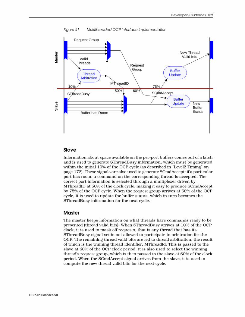
Developers Guidelines 159
Figure 41 Multithreaded OCP Interface Implementation
SlaveInformation about space available on the per-port buffers comes out of a latch and is used to generate SThreadBusy information, which must be generated within the initial 10% of the OCP cycle (as described in “Level2 Timing” on page 172). These signals are also used to generate SCmdAccept: if a particular port has room, a command on the corresponding thread is accepted. The correct port information is selected through a multiplexer driven by MThreadID at 50% of the clock cycle, making it easy to produce SCmdAccept by 75% of the OCP cycle. When the request group arrives at 60% of the OCP cycle, it is used to update the buffer status, which in turn becomes the SThreadBusy information for the next cycle.
MasterThe master keeps information on what threads have commands ready to be presented (thread valid bits). When SThreadBusy arrives at 10% of the OCP clock, it is used to mask off requests, that is any thread that has its SThreadBusy signal set is not allowed to participate in arbitration for the OCP. The remaining thread valid bits are fed to thread arbitration, the result of which is the winning thread identifier, MThreadId. This is passed to the slave at 50% of the OCP clock period. It is also used to select the winning thread’s request group, which is then passed to the slave at 60% of the clock period. When the SCmdAccept signal arrives from the slave, it is used to compute the new thread valid bits for the next cycle.
Mas
ter
Sla
ve
ThreadArbitration
10%50%
ValidThreads
MThreadID
RequestGroup
BufferUpdate
SThreadBusy
Buffer has Room
60%
BufferUpdate
Request Group
75%
New ThreadValid Info
NewBufferStatus
SCmdAccept
OCP-IP Confidential
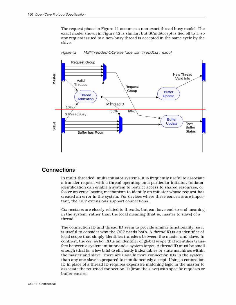
160 Open Core Protocol Specification
The request phase in Figure 41 assumes a non-exact thread busy model. The exact model shown in Figure 42 is similar, but SCmdAccept is tied off to 1, so any request issued to a non-busy thread is accepted in the same cycle by the slave.
Figure 42 Multithreaded OCP Interface with threadbusy_exact
ConnectionsIn multi-threaded, multi-initiator systems, it is frequently useful to associate a transfer request with a thread operating on a particular initiator. Initiator identification can enable a system to restrict access to shared resources, or foster an error logging mechanism to identify an initiator whose request has created an error in the system. For devices where these concerns are impor-tant, the OCP extensions support connections.
Connections are closely related to threads, but can have end-to-end meaning in the system, rather than the local meaning (that is, master to slave) of a thread.
The connection ID and thread ID seem to provide similar functionality, so it is useful to consider why the OCP needs both. A thread ID is an identifier of local scope that simply identifies transfers between the master and slave. In contrast, the connection ID is an identifier of global scope that identifies trans-fers between a system initiator and a system target. A thread ID must be small enough (that is, a few bits) to efficiently index tables or state machines within the master and slave. There are usually more connection IDs in the system than any one slave is prepared to simultaneously accept. Using a connection ID in place of a thread ID requires expensive matching logic in the master to associate the returned connection ID (from the slave) with specific requests or buffer entries.
Mas
ter
Sla
ve
ThreadArbitration
10%50%
ValidThreads
MThreadID
RequestGroup
BufferUpdate
SThreadBusy
Buffer has Room
60%
BufferUpdate
Request Group
New ThreadValid Info
NewBufferStatus
OCP-IP Confidential
Developers Guidelines 161
Using a networking analogy, the thread ID is a level-2 (data link layer) concept, whereas the connection ID is more like a level-3 (transport/session layer) concept. Some OCP slaves only operate at level-2, so it doesn’t make sense to burden them or their masters with the expense of dealing with level-3 resources. Alternatively, some slaves need the features of level-3 connec-tions, so in this case it makes sense to pass the connection ID through to them.
A connection ID is not usually provided by an initiator core on its OCP inter-face but is allocated to that particular initiator in the interconnect logic of the system. The connection ID is system-specific, not core-specific; only the system integrator has the global knowledge of the number of initiators instan-tiated in the application, and what the requirements are in terms of differentiation.
As an exception to that rule, if the global interconnect consists of multiple hierarchical structures, a complete subsystem can be integrated (including another interconnect with multiple embedded initiators). In that case, the OCP interface between the two interconnects should implement the connid extension, so that the end-to-end meaning of that OCP field can be preserved at the system level.
For a target core, the connid extension is included when such features as access control, error logging or similar initiator-related features require initi-ator identification.
OCP Specific Features
Write SemanticsThe OCP-IP 1.0 Specification includes a Write command without a response. From the initiator standpoint, it completes once the request has been accepted, so follows a posted write model. The 2.0 release semantics specify whether a write is posted or not. A non-posted write model is preferred when-ever the originator of the request must be aware of the completion of its write command; An example is clearing an interrupt in a peripheral module using a write command. There the processor must be sure that the interrupt line has been effectively released before it can acknowledge the interrupt service in the chip-level interrupt controller.
The 2.0 extension separates the concept of the posting semantics from the concept of responses on writes in the following ways:
• A write with a response could have posted semantics in a system (so that a response is returned immediately) or it could have non-posted semantics (so that a response is returned only after the write is completed at the final target).
• A write without a response normally has posted semantics and carries forward the OCP-IP 1.0 specification for backward compatibility.
OCP-IP Confidential
162 Open Core Protocol Specification
• A write without a response can be assigned non-posted semantics by not accepting the command until the write has completed, but this is not recommended since it de-pipelines the OCP interface. Since posting makes sense at a system level, adopting a delayed-SCmdAccept scheme can only be efficient locally, with no guarantee of the non-posting semantics at the system level.
The writeresp_enable parameter controls whether writes have responses or not. writenonpost_enable controls whether the interface supports the WriteN-onPost command, giving the initiator core the ability to launch two different types of writes. Table 28 summarizes the choices.
Table 28 Write Parameters
By separating whether writes have responses (writeresp_enable) from whether the core has control over where the responses are generated (writenonpost_enable), the OCP specification provides the following features:
• The simple, posted model remains intact. The simplest cores only implement WR, and need not worry about write responses.
• Cores that can generate or use write responses should enable write responses, providing support for in-band error reporting on write commands. The read and write state machines are duplicated from the standpoint of flow control, producing a simpler design. Such cores would normally only implement the WR command. In this case, the system integrator is in control of where in the write path the write response is generated, allowing a choice of the level of posting based upon performance and coherence trade-offs.
• Cores that can distinguish between performance and coherence (really only CPUs and bridges) can enable WRNP to implement dynamic choice between WR and WRNP. The additional signaling gives the system integrator the dynamic information needed to choose the posting point as the CPU requests. The only practical difference between WR and WRNP at the protocol level is the expected latency between request and response. This permits some embedded CPUs to achieve high performance –particularly as interconnects become pipelined and posting buffers are needed.
writenonpost_enable
writeresp_enable 0 1
0 Simple posted write model, corresponds to OCP-IP1.0 spec
Illegal
1 Initiator core has one flavor of writes (WR), system integrator decides where to post the write requests
Initiator core has two flavors of writes (WR and WRNP), system integrator decides where to post the two different write requests
OCP-IP Confidential
Developers Guidelines 163
When the writeresp_enable parameter is enabled, responses are required for any write command issued on the OCP, including WR, WRNP, but also BCST and WRC.
Use of the Broadcast command must be limited to specific category of designs (some interconnect designs may benefit from simultaneous update through distributed registers). It is not expected that standard cores support the command.
Lazy SynchronizationMost processors support semaphores through a read-modify-write type of instruction and swap, test-and-set, etc. Using an OCP interconnect, these instructions are mapped onto a pair of OCP commands. A RDEX command sets a lock to the memory location, followed by a WR (or WRNP) command to release the lock. The system must ensure that no other thread will be granted access to that memory location between the RDEX and the unlocking WR.
Because the Write that clears the lock must immediately follow the ReadEx (on the same thread), only a limited number of operations can be performed by a processor between RDEX and WR. Because competing requests to the locked location are also blocked from proceeding until the lock is released, you could lock part of the interconnect for the duration of the RDEX-WR or WRNP pair. Such a mechanism, often referred to as locked synchronization, is efficient for handling exclusive accesses to a shared resource, but can result in a significant performance loss when used extensively.
For these reasons, some processors use non-blocking instructions for sema-phore handling, breaking the atomicity of the exclusive read/write pair. For the processor, this allows other instructions to be executed by the processor between the read and write accesses. For the system interconnect, it allows requests from other threads to be inserted between the read and write commands. Referred to as lazy synchronization, this mechanism requires new read and write semantics, commonly known as LL/SC semantics, for Load-Linked and Store-Conditional.
OCP-IP 2.0 support for lazy synchronization uses the ReadLinked, and Write-Conditional commands. A single OCP parameter rdlwrc_enable is set to 1, to enable the commands. Because some processors might use both semantics (locked and lazy), the OCP interface supports RDEX, RDL, WR(WRNP) and WRC.
The system relies upon the existence of monitor logic, that can be located either in the system interconnect, or in the memory controller. The ReadLinked command sets a reservation in the logic, associating the accessing thread with a particular address. The WriteConditional command, being transmitted on the same thread, is locally transformed into a memory write access only if the reservation is still set when the command is received. As the tagged address is not locked, the tag can be reset by competing traffic directed to the same location from other threads between RDL and WRC.
Consequently, the WRC command expects a response from the monitor logic, reflecting whether the write operation has been performed. To answer that requirement, OCP-IP 2.0 provides the value, FAIL for the SResp field (meaning
OCP-IP Confidential
164 Open Core Protocol Specification
that writeresp_enable is on if rdlwrc_enable is on). WRC is the only OCP-IP 2.0 command that makes use of the FAIL code, though new commands in future revisions may. FAIL responses are frequently received in a system using lazy synchronization that operates normally. Do not confuse FAIL with SResp=ERR, which effectively signals a system interconnect error or a target error.
Both RDL and WRC commands assume a single transaction model and cannot be used in a burst.
The semantics of lazy synchronization are defined in the specification section of this document (Part I). Some specific sequences resulting from the usage of the RDL and WRC semantics are:
• A thread can issue more than one RDL before issuing a WRC, or issue more than one RDL without issuing WRC. Whether the subsequent RDL clears the reservation or sets a new one is implementation-specific, depending on the number of hardware monitors. At least one monitor per thread is required.
• If a thread issues a WR or WRNP command to an address it previously tagged with a RDL command, the write access clears all reservations from other threads for the same address (but not its own reservation).
• If a thread issues a WRC without having issued a RDL, the WRC will fail.
• If a thread issues a RDEX between the RDL and WRC, the RDEX is executed, sets the lock and waits for the corresponding write to clear the lock. RDL-WRC reservations will not be affected by the RDEX. The WR or WRNP that clears the lock, also clears any reservation set by other initiators for the same address (with the same MAddr, MByteEn and MAddrSpace if applicable).
Because competing requests of any type from other threads to a locked (by RDEX) location are blocked from proceeding until the lock is released, a RDEX command being issued between RDL and WRC commands, also blocks the WRC until the WR or WRNP command clearing the lock is issued. This favours RDEX-WR or WRNP sequence over RDL-WRC, in the sense that competing RDEX-WR or WRNP and RDL-WRC sequences will always result in having the RDEX-WR or WRNP sequence win.
Incorrect use of the two synchronization mechanisms can result in deadlock so for example, the sequence of commands shown in Figure 43 might result in a deadlock. In this example Processor 1 tries to release the semaphore using RDL-WRC commands, Processor 2 tries to acquire the semaphore using RDEX-WR or WRNP commands. The RDEX-WR or WRNP sequence always occurs between the RDL and WRC. Because the WR or WRNP clearing the lock in Processor2 will also clear the reservation for Processor 1, the RDL-WRC sequence will never succeed. Processor 1 will never be able to release the lock or Processor2 to acquire it.
OCP-IP Confidential
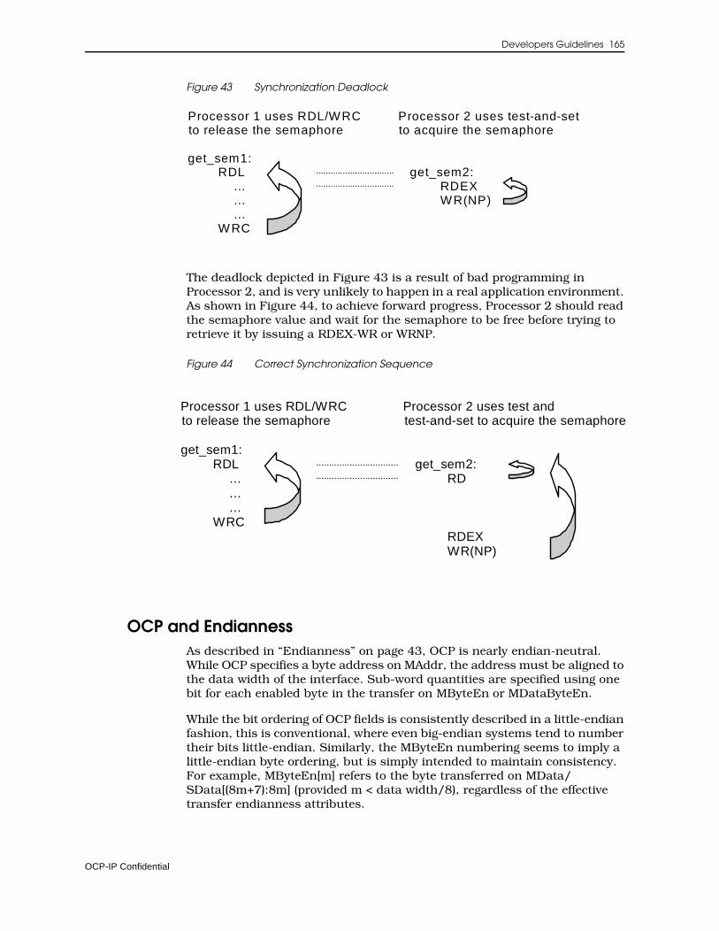
Developers Guidelines 165
Figure 43 Synchronization Deadlock
The deadlock depicted in Figure 43 is a result of bad programming in Processor 2, and is very unlikely to happen in a real application environment. As shown in Figure 44, to achieve forward progress, Processor 2 should read the semaphore value and wait for the semaphore to be free before trying to retrieve it by issuing a RDEX-WR or WRNP.
Figure 44 Correct Synchronization Sequence
OCP and EndiannessAs described in “Endianness” on page 43, OCP is nearly endian-neutral. While OCP specifies a byte address on MAddr, the address must be aligned to the data width of the interface. Sub-word quantities are specified using one bit for each enabled byte in the transfer on MByteEn or MDataByteEn.
While the bit ordering of OCP fields is consistently described in a little-endian fashion, this is conventional, where even big-endian systems tend to number their bits little-endian. Similarly, the MByteEn numbering seems to imply a little-endian byte ordering, but is simply intended to maintain consistency. For example, MByteEn[m] refers to the byte transferred on MData/SData[(8m+7):8m] (provided m < data width/8), regardless of the effective transfer endianness attributes.
Processor 1 uses RDL/WRCto release the semaphore
get_sem1:RDL
………
WRC
Processor 2 uses test-and-setto acquire the semaphore
get_sem2:RDEXWR(NP)
Processor 1 uses RDL/WRCto release the semaphore
get_sem1:RDL
………
WRC
Processor 2 uses test andtest-and-set to acquire the semaphore
get_sem2:RD
RDEXWR(NP)
OCP-IP Confidential
166 Open Core Protocol Specification
If the master OCP and the slave OCP are the same data width, endianness does not matter. Addresses, data, and byte enables must remain consistent across both interfaces. (There are exceptions, since packed sub-word data objects should be swapped if the endianness does not match. OCP does not carry the required signaling to determine sub-word sizes, so full-word trans-fers must be assumed.)
Endianness problems arise as soon as one looks to connect a master and slave with different data widths. The narrow side has extra (non-zero) address bits, since its word-aligned addresses do not force as many bits to be zero. The wide side has extra byte lanes to carry its wider words. The association of the extra address bits (narrow side) with the extra byte lanes (wide side) specifies an endianness.
To bridge interfaces that suffer from mismatched data widths, packing and unpacking is required. Data width conversion must make some assumptions about the correspondence between the MAddr least-significant bits and the MByteEn field.
If the association maps the low-order byte lanes to lower addresses, the data width conversion is performed in a little-endian manner. If the association maps the high-order byte lanes to lower addresses, the data width conversion is performed in a big-endian manner. This operation is absolutely not an endi-anness conversion, but rather an endianness-aware packing or unpacking operation, so that the transaction endianness is preserved across the data width converter.
There is no attempt to perform any endian conversion in hardware. Rather, the goal is to enable interconnects that are essentially endian-neutral, but become endian-adaptive to match the endianness of the attached entities. This implies that the native endianness of an OCP core must be specified. OCP-IP 2.0 captures that property using the endian parameter, which can take four values:
LITTLEQualifies little-endian only cores
BIGQualifies big-endian only cores
BOTHQualifies cores that can change endianness:
- Based upon an external input such as a CPU that statically selects its endianness at boot time
- Based upon an internal configuration register such as a DMA engine, that generates OCP read and write requests in accordance with the endianness of the target, as stated by the DMA programmer
- Cores that support dynamic endianness
OCP-IP Confidential
Developers Guidelines 167
NEUTRALQualifies cores that have no inherent endianness. Examples are simple memory devices that only work with full OCP-word quantities, or peripheral devices, the endianness of which can be controlled by the software device driver.
While not supported by the OCP-IP 2.0 standard set of features, it is possible to define a dynamic endian-aware interconnect using in-band information. By specifying the parameters reqinfo (for request packing / unpacking control), mdatainfo (for data packing / unpacking control when datahandshake is enabled), and respinfo (for response packing / unpacking control), the defi-nition of all these qualifiers is then platform-specific.
Sideband SignalsThe sideband signals provide a means of transmitting control-oriented infor-mation. Since the signals are rarely performance sensitive, implementors are strongly encouraged to ensure that all sideband signals are driven stable very early in the OCP clock cycle; that is, that sideband outputs come directly out of core flip-flops. Sideband inputs should similarly be allowed to arrive very late in the OCP clock cycle; that is, sideband inputs should be registered almost immediately by the receiving core.
Cores that do not implement this conservative timing may require modifica-tion to achieve timing convergence.
Reset HandlingMany systems are fully satisfied with a single reset signal applied to both the master and the slave on an OCP interface. Either the master or the slave can drive the reset, or a third entity, such as a chip level reset manager, can provide it to both master and slave.
In some situations, it is more convenient for the master and slave to employ their own reset domains and communicate these internal resets to one another. The OCP interface is unable to communicate until both sides are out of reset since the side still in reset may be driving undetermined values (X) on their OCP outputs and cause problems for the side that is already out of reset. Examples of cases where this might arise are:
• A core with multiple OCP interfaces that are connected to different interconnects, which are each in different reset domains, plus the core has its own internal reset domain.
• Two connected interconnects with both acting as initiators of transfers and each with their own reset domain.
Adding a second reset signal to the interface allows each master and slave to have both a reset output and input. The composite reset state for the OCP interface is established as the combination of the two resets, so that either side (or both) asserting reset causes the interface to be in reset. While in reset, the existing rules about the interface state and signal values apply.
OCP-IP Confidential
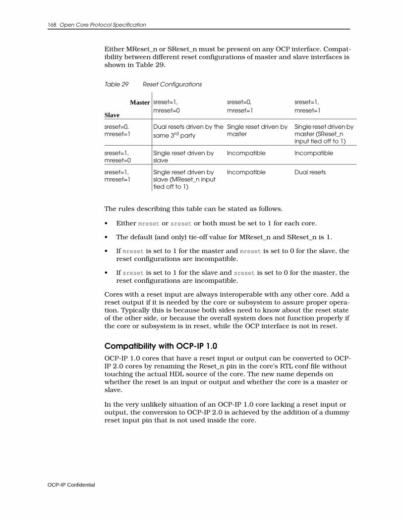
168 Open Core Protocol Specification
Either MReset_n or SReset_n must be present on any OCP interface. Compat-ibility between different reset configurations of master and slave interfaces is shown in Table 29.
Table 29 Reset Configurations
The rules describing this table can be stated as follows.
• Either mreset or sreset or both must be set to 1 for each core.
• The default (and only) tie-off value for MReset_n and SReset_n is 1.
• If mreset is set to 1 for the master and mreset is set to 0 for the slave, the reset configurations are incompatible.
• If sreset is set to 1 for the slave and sreset is set to 0 for the master, the reset configurations are incompatible.
Cores with a reset input are always interoperable with any other core. Add a reset output if it is needed by the core or subsystem to assure proper opera-tion. Typically this is because both sides need to know about the reset state of the other side, or because the overall system does not function properly if the core or subsystem is in reset, while the OCP interface is not in reset.
Compatibility with OCP-IP 1.0OCP-IP 1.0 cores that have a reset input or output can be converted to OCP-IP 2.0 cores by renaming the Reset_n pin in the core’s RTL conf file without touching the actual HDL source of the core. The new name depends on whether the reset is an input or output and whether the core is a master or slave.
In the very unlikely situation of an OCP-IP 1.0 core lacking a reset input or output, the conversion to OCP-IP 2.0 is achieved by the addition of a dummy reset input pin that is not used inside the core.
Master
Slave
sreset=1,mreset=0
sreset=0,mreset=1
sreset=1,mreset=1
sreset=0,mreset=1
Dual resets driven by the
same 3rd party
Single reset driven by master
Single reset driven by master (SReset_n input tied off to 1)
sreset=1,mreset=0
Single reset driven by slave
Incompatible Incompatible
sreset=1,mreset=1
Single reset driven by slave (MReset_n input tied off to 1)
Incompatible Dual resets
OCP-IP Confidential
Developers Guidelines 169
Debug and Test InterfaceThere are three debug and test interface extensions predefined for the OCP: scan, clock control, and IEEE 1149. The scan extension enables internal scan techniques, either in a pre-designed hard-core or end user inserted into a soft-core. Clock control extensions assist in scan testing and debug when the IP core has at least one other clock domain that is not derived from Clk. The IEEE 1149 extension is for interfacing to cores that have an IEEE 1149.1 test access port built-in and accessible. This is primarily the case with cores, such as microprocessors, that were derived from standalone products.
These three extensions along with sideband signals (flags) can yield a highly debuggable and testable IP core and device.
Scan ControlThe width and meaning of the Scanctrl field is user-defined. At a minimum this field carries a signal to specify when the device is in scan chain shifting mode. The signal can be used for the scan clock if scan-clock style flip-flops are being used. When this is a multi-bit field, another common signal to carry would be one specifying the scan mode. This signal can be used to put the IP core into any special test mode that is necessary before scanning and appli-cation of ATPG vectors can begin.
Clock ControlThe clock control test extensions are included to ease the integration of IP cores into full or partial scan test environments and support of debug scan operations in designs that use clock sources other than Clk.
When an external clock source exists (for example, non-Clk derived clock), the ClkByp signal specifies a bypass of the external clock. In that case the TestClk signal usually becomes the clock source. The TestClk toggles in the correct sequence for applying ATPG vectors, stopping the internal clocks, and doing scan dumps as required by the user.
OCP-IP Confidential

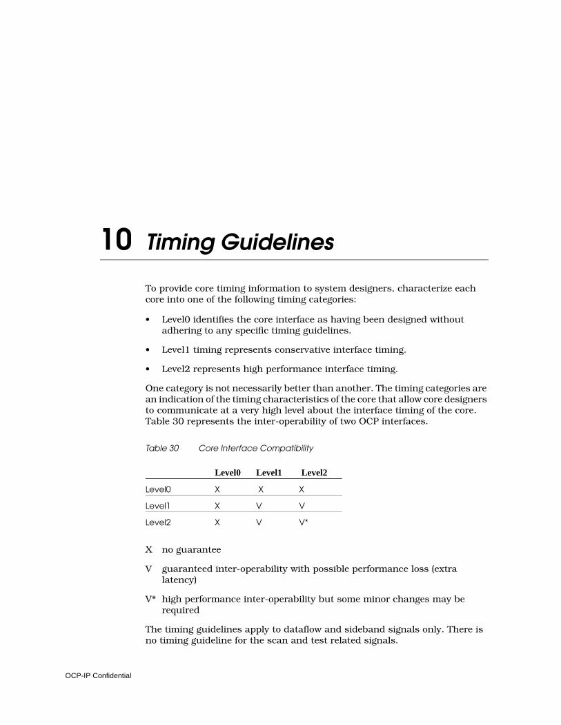
10 Timing Guidelines
To provide core timing information to system designers, characterize each core into one of the following timing categories:
• Level0 identifies the core interface as having been designed without adhering to any specific timing guidelines.
• Level1 timing represents conservative interface timing.
• Level2 represents high performance interface timing.
One category is not necessarily better than another. The timing categories are an indication of the timing characteristics of the core that allow core designers to communicate at a very high level about the interface timing of the core. Table 30 represents the inter-operability of two OCP interfaces.
Table 30 Core Interface Compatibility
X no guarantee
V guaranteed inter-operability with possible performance loss (extra latency)
V* high performance inter-operability but some minor changes may be required
The timing guidelines apply to dataflow and sideband signals only. There is no timing guideline for the scan and test related signals.
Level0 Level1 Level2
Level0 X X X
Level1 X V V
Level2 X V V*
OCP-IP Confidential
172 Open Core Protocol Specification
Timing numbers are specified as a percentage of the minimum supported clock-cycle (at maximum operating frequency). If a core is specified at 100MHz and the c2qtime is given as 30%, the actual c2qtime is 3ns.
Level0 Timing Level0 timing indicates that the core developer has not followed any specific guideline in designing the core interface. There is no guarantee that the inter-face can operate with any other core interface. Inter-operability for the core will need to be determined by comparing timing specifications for two inter-faces on a per-signal basis.
Level1 Timing Level1 timing indicates that a core has been developed for minimum timing work during system integration. The core uses no more than 25% of the clock period for any of its signals, either at the input (setuptime) or at the output (outputtime). A core interface in this category must not use any of the combi-national paths allowed in the OCP interface.
Since inputs and outputs each only use 25%, 50% of the cycle remains avail-able. This means that a Level1 core can always connect to other Level1 and Level2 cores without requiring any additional modification.
Level2 Timing Level2 timing indicates that a core interface has been developed for high performance timing. A Level2 compliant core provides or uses signals according to the timing values shown in Table 31. There are separate values for single-threaded and multi-threaded OCP interfaces. The number for each signal indicates the percentage of the minimum cycle time at which the signal is available, that is the outputtime at the output. setuptime at the input is calculated by subtracting the number given from the minimum cycle time. For example, a time of 30% indicates that the outputtime is 30% and the setup-time is 70% of the minimum clock period.
In addition to meeting the timing indicated in Table 31, a Level2 compliant core must not use any combinational paths other than the preferred paths listed in Table 32.
There is no margin between outputtime and setuptime. When using Level2 cores, extra work may be required during the physical design phase of the chip to meet timing requirements for a given technology/library.
OCP-IP Confidential

Timing Guidelines 173
Table 31 Level2 Signal Timing
Table 32 Allowed Combinational Paths for Level2 Timing
SignalSingle-threaded Interface %
Multi-threaded Interface %
Control, Status 25 25
ControlBusy, StatusBusy 10 10
ControlWr, StatusRd 25 25
Datahandshake Group(excluding MDataThreadID)
30 60
MDataThreadID n/a 50
MRespAccept 50 75
MThreadBusy 10 10
MThreadID n/a 50
Request Group(excluding MThreadID)
30 60
MReset_n, SReset_n 10 10
Response Group (excluding SThreadID) 30 60
SCmdAccept 50 75
SDataAccept 50 75
SDataThreadBusy 10 10
SError, SFlag, SInterrupt, MFlag, MError 40 40
SThreadBusy 10 10
SThreadID n/a 50
Core From To
Master SThreadBusy Request Group
SThreadBusySDataThreadBusy
Datahandshake Group
Response Group MRespAccept
Slave MThreadBusy Response Group
Request Group SCmdAccept andSDataAccept
Datahandshake Group SCmdAccept andSDataAccept
OCP-IP Confidential

11 OCP Profiles
A strength of OCP is the ability to configure an interface to match a core’s communication requirements. Developing an OCP configuration can be chal-lenging for a new user. This chapter provides profiles that capture the OCP features associated with standard communication functions. The pre-defined profiles help map the requirements of a new core to OCP configuration guide-lines. The expected benefits include:
• Reduced risk of incompatibility when integrating OCP based cores originating from different providers
• Reduced learning curve in applying OCP for standard purposes
• Simplified circuitry needed to bridge an OCP based core to another communication interface standard
• Improved core maintenance
• Simplified creation of reusable core test benches
Profiles address only the OCP interface, with each profile consisting of OCP interface signals, specific protocol features, and application guidelines. For cores natively equipped with OCP interfaces, profiles minimize the number of interface and protocol options that need to be considered.
Two sets of OCP profiles are provided: profiles for new IP cores implementing native OCP interfaces and profiles that are targeted at designers of bridges between OCP and other bus protocols.
Since the other bus protocols may have several implementation flavors that require custom OCP parameter sets, the bridging profiles are incomplete. The bridging profiles can be used with OCP serving as either a master or a slave.
OCP-IP Confidential
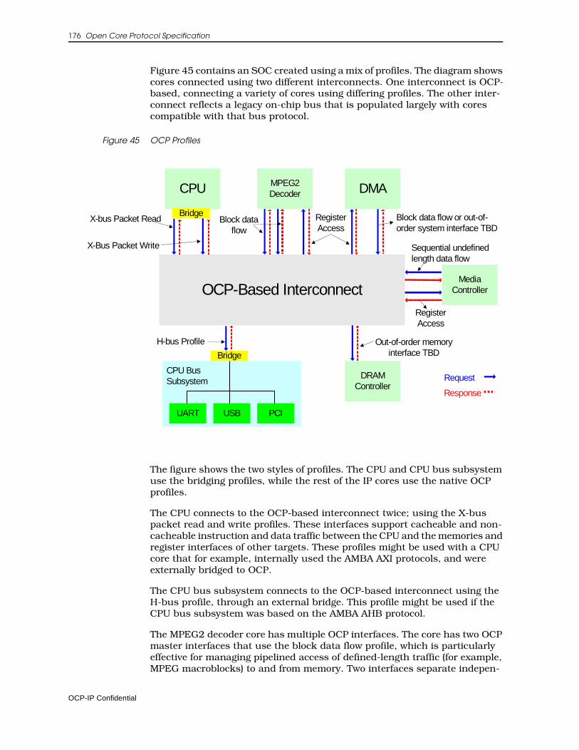
176 Open Core Protocol Specification
Figure 45 contains an SOC created using a mix of profiles. The diagram shows cores connected using two different interconnects. One interconnect is OCP-based, connecting a variety of cores using differing profiles. The other inter-connect reflects a legacy on-chip bus that is populated largely with cores compatible with that bus protocol.
Figure 45 OCP Profiles
The figure shows the two styles of profiles. The CPU and CPU bus subsystem use the bridging profiles, while the rest of the IP cores use the native OCP profiles.
The CPU connects to the OCP-based interconnect twice; using the X-bus packet read and write profiles. These interfaces support cacheable and non-cacheable instruction and data traffic between the CPU and the memories and register interfaces of other targets. These profiles might be used with a CPU core that for example, internally used the AMBA AXI protocols, and were externally bridged to OCP.
The CPU bus subsystem connects to the OCP-based interconnect using the H-bus profile, through an external bridge. This profile might be used if the CPU bus subsystem was based on the AMBA AHB protocol.
The MPEG2 decoder core has multiple OCP interfaces. The core has two OCP master interfaces that use the block data flow profile, which is particularly effective for managing pipelined access of defined-length traffic (for example, MPEG macroblocks) to and from memory. Two interfaces separate indepen-
OCP-Based Interconnect
CPU
MediaController
DMAMPEG2Decoder
DRAMController
CPU BusSubsystem
UART PCIUSB
Bridge
Bridge
H-bus Profile
X-bus Packet Read
X-Bus Packet Write
Block dataflow
RegisterAccess
Block data flow or out-of-order system interface TBD
Sequential undefinedlength data flow
Out-of-order memoryinterface TBD
RegisterAccess
Request
Response
OCP-IP Confidential
OCP Profiles 177
dent traffic, enabling additional parallelism and higher peak performance without using OCP threads. The core also has an OCP slave interface that uses the register access profile, providing the control processor (in this case, the CPU) with the ability to program the operation of the decoder.
The DMA and media controllers also include register access, profile-based slave interfaces, enabling CPU control over their operation.
The principle data flow interface of the DMA controller is through its OCP master interface. Depending upon the degree of parallelism needed by the controller, it could either follow the block data flow profile, or exploit thread-level parallelism using the out-of-order system interface profile (which is not included in this revision of the Specification).
The OCP master interface of the media controller uses the sequential unde-fined length profile to communicate a data stream with a memory based buffer. Because of the sequential undefined length characteristics of a data stream, this profile is a good fit for the media controller. In this example, pack-etization for transport at the OCP based interconnect level would be left to the interconnect.
A shared SDRAM controller core is attached to the OCP-based interconnect using a slave OCP interface. As this controller optimizes bank and page accesses to SDRAM, it can minimize local buffering, maximize throughput, and minimize latency by re-ordering requests. It therefore uses the out-of-order memory interface profile (which is not included in this revision of the Specification) to leverage both OCP threads and tags to fully exploit transac-tion parallelism.
Profile TypesThe initial set of profiles cover the most common core communication require-ments. Each OCP profile defines one or more applications. The profiles available for this release are:
• Block data flow
• Sequential undefined length data flow
• Register access
• Simple H-bus
• X-bus packet write
• X-bus packet read
Each profile addresses distinct OCP interfaces, though most systems constructed using OCP will have a mix of functional elements. As different cores and subsystems have diverse communication characteristics and constraints, various profiles will prove useful at different interfaces within the system.
OCP-IP Confidential
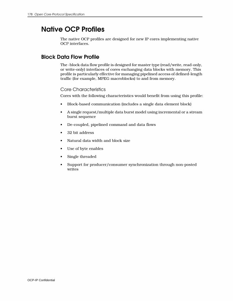
178 Open Core Protocol Specification
Native OCP ProfilesThe native OCP profiles are designed for new IP cores implementing native OCP interfaces.
Block Data Flow ProfileThe -block data flow profile is designed for master type (read/write, read-only, or write-only) interfaces of cores exchanging data blocks with memory. This profile is particularly effective for managing pipelined access of defined-length traffic (for example, MPEG macroblocks) to and from memory.
Core CharacteristicsCores with the following characteristics would benefit from using this profile:
• Block-based communication (includes a single data element block)
• A single request/multiple data burst model using incremental or a stream burst sequence
• De-coupled, pipelined command and data flows
• 32 bit address
• Natural data width and block size
• Use of byte enables
• Single threaded
• Support for producer/consumer synchronization through non-posted writes
OCP-IP Confidential
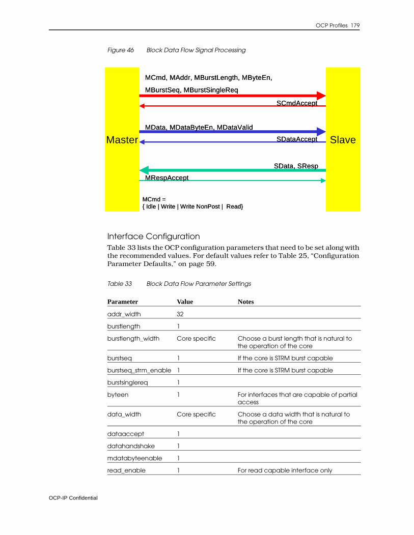
OCP Profiles 179
Figure 46 Block Data Flow Signal Processing
Interface ConfigurationTable 33 lists the OCP configuration parameters that need to be set along with the recommended values. For default values refer to Table 25, “Configuration Parameter Defaults,” on page 59.
Table 33 Block Data Flow Parameter Settings
Parameter Value Notes
addr_width 32
burstlength 1
burstlength_width Core specific Choose a burst length that is natural to the operation of the core
burstseq 1 If the core is STRM burst capable
burstseq_strm_enable 1 If the core is STRM burst capable
burstsinglereq 1
byteen 1 For interfaces that are capable of partial access
data_width Core specific Choose a data width that is natural to the operation of the core
dataaccept 1
datahandshake 1
mdatabyteenable 1
read_enable 1 For read capable interface only
Master Slave
MCmd, MAddr, MBurstLength, MByteEn,
MBurstSeq, MBurstSingleReq
MData, MDataByteEn, MDataValid
SData, SResp
SCmdAccept
SDataAccept
MRespAccept
MCmd ={ Idle | Write | Write NonPost | Read}
Master Slave
MCmd, MAddr, MBurstLength, MByteEn,
MBurstSeq, MBurstSingleReq
MData, MDataByteEn, MDataValid
SData, SResp
SCmdAccept
SDataAccept
MRespAccept
MCmd ={ Idle | Write | Write NonPost | Read}
OCP-IP Confidential
180 Open Core Protocol Specification
Implementation NotesWhen implementing this profile, consider the following suggestions:
• Start read transactions as early as possible to minimize read latency behind ongoing transactions.
• To implement a synchronization scheme (typically the case when data written by the IP core to shared memory is read by another core in the system), the IP core should issue a synchronization request (for instance through an OCP flag interface) only after receiving notification that the last write transaction is complete. To accomplish this step, perform all write transactions up to the last one as posted writes. Make the final write transaction a non-posted write. This will lead to reception of a response once the non-posted write transaction has completed.
• Error responses should lead to an interrupt.
respaccept 1
write_enable 1 For write capable interface only
writenonpost_enable 1 See note on synchronization below
writeresp_enable 1
Parameter Value Notes
OCP-IP Confidential
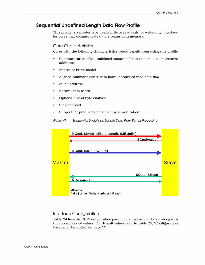
OCP Profiles 181
Sequential Undefined Length Data Flow ProfileThis profile is a master type (read/write or read-only, or write-only) interface for cores that communicate data streams with memory.
Core CharacteristicsCores with the following characteristics would benefit from using this profile:
• Communication of an undefined amount of data elements to consecutive addresses
• Imprecise burst model
• Aligned command/write data flows, decoupled read data flow
• 32 bit address
• Natural data width
• Optional use of byte enables
• Single thread
• Support for producer/consumer synchronization
Figure 47 Sequential Undefined Length Data Flow Signals Processing
Interface ConfigurationTable 34 lists the OCP configuration parameters that need to be set along with the recommended values. For default values refer to Table 25, “Configuration Parameter Defaults,” on page 59.
Master Slave
MCmd, MAddr, MBurstLength, (MByteEn)
MData, (MDataByteEn)
SData, SResp
SCmdAccept
MRespAccept
MCmd ={ Idle | Write | Write NonPost | Read}
Master Slave
MCmd, MAddr, MBurstLength, (MByteEn)
MData, (MDataByteEn)
SData, SResp
SCmdAccept
MRespAccept
MCmd ={ Idle | Write | Write NonPost | Read}
OCP-IP Confidential
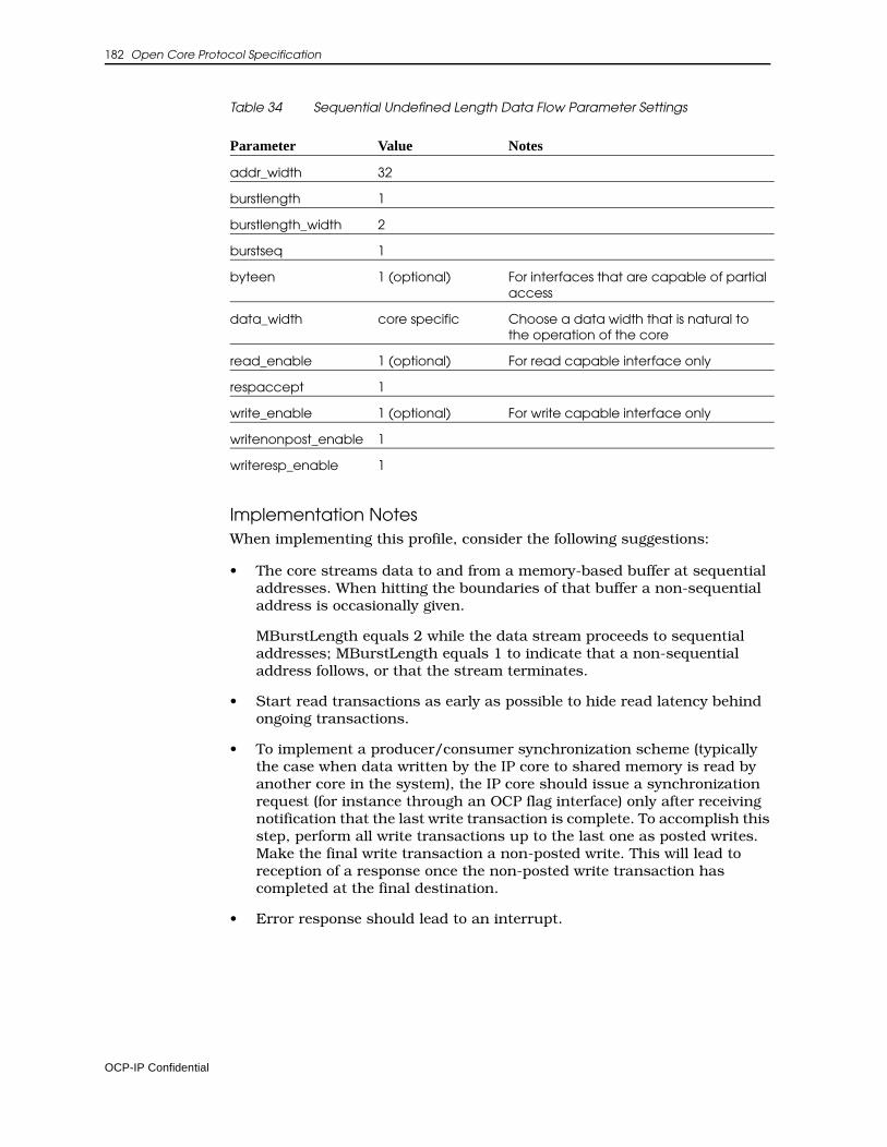
182 Open Core Protocol Specification
Table 34 Sequential Undefined Length Data Flow Parameter Settings
Implementation NotesWhen implementing this profile, consider the following suggestions:
• The core streams data to and from a memory-based buffer at sequential addresses. When hitting the boundaries of that buffer a non-sequential address is occasionally given.
MBurstLength equals 2 while the data stream proceeds to sequential addresses; MBurstLength equals 1 to indicate that a non-sequential address follows, or that the stream terminates.
• Start read transactions as early as possible to hide read latency behind ongoing transactions.
• To implement a producer/consumer synchronization scheme (typically the case when data written by the IP core to shared memory is read by another core in the system), the IP core should issue a synchronization request (for instance through an OCP flag interface) only after receiving notification that the last write transaction is complete. To accomplish this step, perform all write transactions up to the last one as posted writes. Make the final write transaction a non-posted write. This will lead to reception of a response once the non-posted write transaction has completed at the final destination.
• Error response should lead to an interrupt.
Parameter Value Notes
addr_width 32
burstlength 1
burstlength_width 2
burstseq 1
byteen 1 (optional) For interfaces that are capable of partial access
data_width core specific Choose a data width that is natural to the operation of the core
read_enable 1 (optional) For read capable interface only
respaccept 1
write_enable 1 (optional) For write capable interface only
writenonpost_enable 1
writeresp_enable 1
OCP-IP Confidential
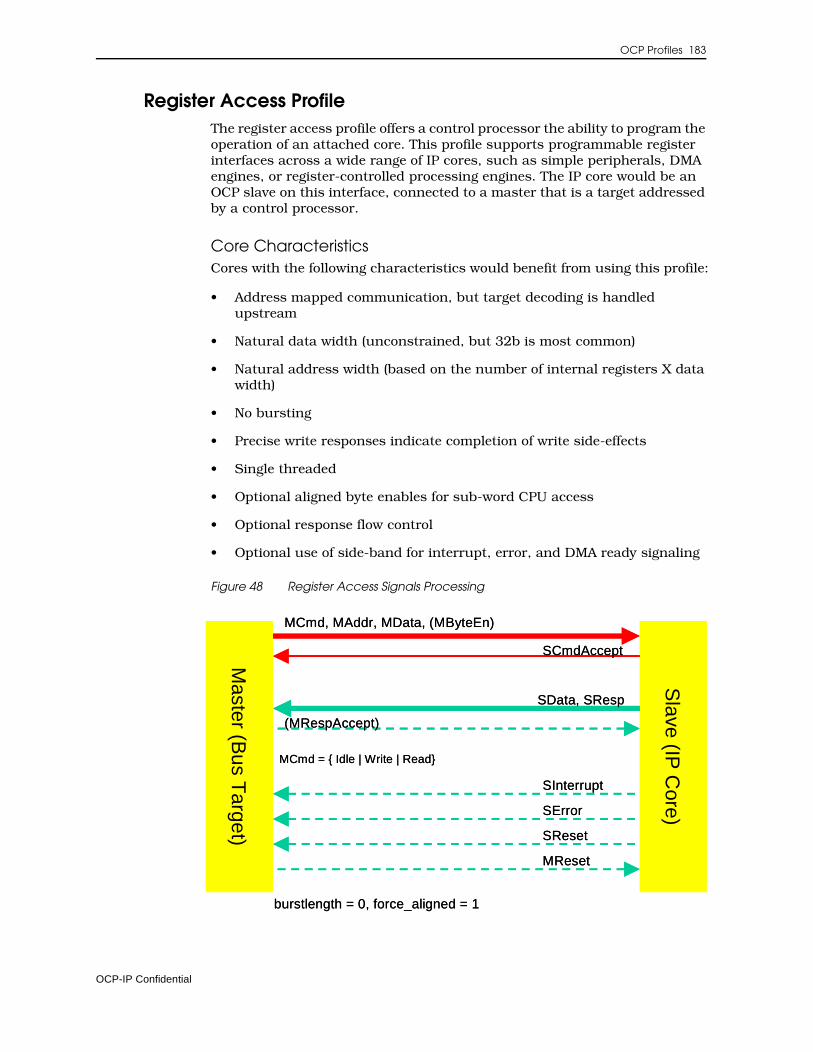
OCP Profiles 183
Register Access ProfileThe register access profile offers a control processor the ability to program the operation of an attached core. This profile supports programmable register interfaces across a wide range of IP cores, such as simple peripherals, DMA engines, or register-controlled processing engines. The IP core would be an OCP slave on this interface, connected to a master that is a target addressed by a control processor.
Core CharacteristicsCores with the following characteristics would benefit from using this profile:
• Address mapped communication, but target decoding is handled upstream
• Natural data width (unconstrained, but 32b is most common)
• Natural address width (based on the number of internal registers X data width)
• No bursting
• Precise write responses indicate completion of write side-effects
• Single threaded
• Optional aligned byte enables for sub-word CPU access
• Optional response flow control
• Optional use of side-band for interrupt, error, and DMA ready signaling
Figure 48 Register Access Signals ProcessingM
aster (Bus T
arget)
Slave (IP
Core)
MCmd, MAddr, MData, (MByteEn)
SData, SResp
SCmdAccept
(MRespAccept)
MCmd = { Idle | Write | Read}
burstlength = 0, force_aligned = 1
SInterrupt
SError
SReset
MReset
Master (B
us Target)
Slave (IP
Core)
MCmd, MAddr, MData, (MByteEn)
SData, SResp
SCmdAccept
(MRespAccept)
MCmd = { Idle | Write | Read}
burstlength = 0, force_aligned = 1
SInterrupt
SError
SReset
MReset
OCP-IP Confidential
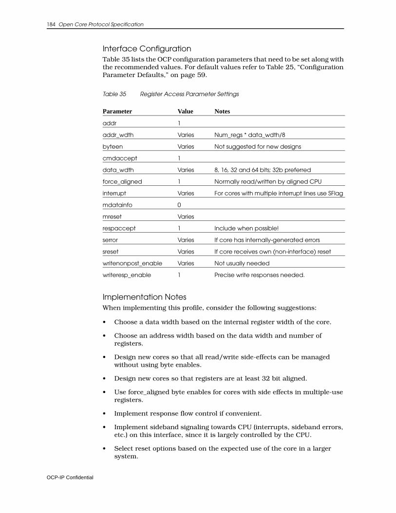
184 Open Core Protocol Specification
Interface ConfigurationTable 35 lists the OCP configuration parameters that need to be set along with the recommended values. For default values refer to Table 25, “Configuration Parameter Defaults,” on page 59.
Table 35 Register Access Parameter Settings
Implementation NotesWhen implementing this profile, consider the following suggestions:
• Choose a data width based on the internal register width of the core.
• Choose an address width based on the data width and number of registers.
• Design new cores so that all read/write side-effects can be managed without using byte enables.
• Design new cores so that registers are at least 32 bit aligned.
• Use force_aligned byte enables for cores with side effects in multiple-use registers.
• Implement response flow control if convenient.
• Implement sideband signaling towards CPU (interrupts, sideband errors, etc.) on this interface, since it is largely controlled by the CPU.
• Select reset options based on the expected use of the core in a larger system.
Parameter Value Notes
addr 1
addr_wdth Varies Num_regs * data_wdth/8
byteen Varies Not suggested for new designs
cmdaccept 1
data_wdth Varies 8, 16, 32 and 64 bits; 32b preferred
force_aligned 1 Normally read/written by aligned CPU
interrupt Varies For cores with multiple interrupt lines use SFlag
mdatainfo 0
mreset Varies
respaccept 1 Include when possible!
serror Varies If core has internally-generated errors
sreset Varies If core receives own (non-interface) reset
writenonpost_enable Varies Not usually needed
writeresp_enable 1 Precise write responses needed.
OCP-IP Confidential
OCP Profiles 185
• Use regular Write commands for precise completion, unless the core is capable of per-transfer posting decisions, where mixing Write and WriteNonPost helps.
Bridging ProfilesThese profiles are designed to simplify or automate the creation of bridges to other interface protocols. The bridge can have an OCP master or slave port. There are two types:
• The simple H-bus profile is intended to provide a connection through an external bridge, for example to a CPU with an AMBA AHB protocol.
• The X-bus interfaces support cacheable and non-cacheable instruction and data traffic between a CPU and the memories and register interfaces of other targets. The X-bus profiles might be used with a CPU core that internally used the AMBA AXI protocols, and were externally bridged to OCP.
Simple H-bus ProfileThis profile allows you to create OCP master wrappers to native interfaces of simple CPU type initiators with multiple-request/multiple-data, read and write transactions.
Core CharacteristicsCores with the following characteristics would benefit from using this profile:
• Address mapped communication
• Natural address width
• Byte enable
• Natural data width
• Constrained burst size
• Single thread
• Caching and similar extensions mapped to MReqInfo or corresponding OCP commands
OCP-IP Confidential
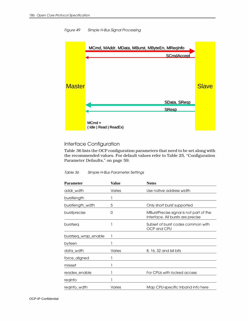
186 Open Core Protocol Specification
Figure 49 Simple H-Bus Signal Processing
Interface ConfigurationTable 36 lists the OCP configuration parameters that need to be set along with the recommended values. For default values refer to Table 25, “Configuration Parameter Defaults,” on page 59.
Table 36 Simple H-Bus Parameter Settings
Parameter Value Notes
addr_wdth Varies Use native address width
burstlength 1
burstlength_wdth 5 Only short burst supported
burstprecise 0 MBurstPrecise signal is not part of the interface. All bursts are precise
burstseq 1 Subset of burst codes common with OCP and CPU
burstseq_wrap_enable 1
byteen 1
data_wdth Varies 8, 16, 32 and 64 bits
force_aligned 1
mreset 1
readex_enable 1 For CPUs with locked access
reqinfo 1
reqinfo_wdth Varies Map CPU-specific inband info here
Master Slave
MCmd, MAddr, MData, MBurst, MByteEn, MReqInfo
SData, SResp
SCmdAccept
SResp
MCmd ={ Idle | Read | ReadEx}
Master Slave
MCmd, MAddr, MData, MBurst, MByteEn, MReqInfo
SData, SResp
SCmdAccept
SResp
MCmd ={ Idle | Read | ReadEx}
OCP-IP Confidential
OCP Profiles 187
Implementation NotesWhen implementing this profile, consider the following suggestions:
• If the CPU’s burst parameters such as data alignment are not supported in OCP, such bursts are broken into single transactions.
• All requests have a response.
• If the CPU address and write data are pipelined, the OCP bridge will align them.
• CPU specific information is mapped to the MReqInfo field, however, since this field is often used for proprietary bits by OCP users, a precise bit-to-bit mapping is not provided. For this field concatenate bit fields starting from bit 0. If the inband field contains control information that has equivalent native OCP functionality, map the information to the corresponding OCP request. For example, a bit that can be buffered can be mapped to OCP posted or non-posted write types.
X-Bus Packet Write ProfileThis profile is designed to create OCP master wrappers to native interfaces of CPU type initiators with single-request/multiple-data, write-only transactions.
Core CharacteristicsCores with the following characteristics would benefit from using this profile:
• Packet type communication
• Natural address width
• Separate command/write data handshake
• Byte enable
• Natural data width
• Multi-thread (blocking)
• Caching and similar extensions mapped to MReqInfo
reqlast 1 Can be created of burst length
respaccept 1
sreset 1
writeresp_enable 1
Parameter Value Notes
OCP-IP Confidential
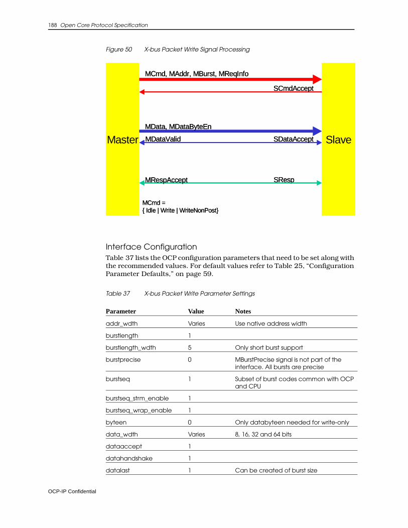
188 Open Core Protocol Specification
Figure 50 X-bus Packet Write Signal Processing
Interface ConfigurationTable 37 lists the OCP configuration parameters that need to be set along with the recommended values. For default values refer to Table 25, “Configuration Parameter Defaults,” on page 59.
Table 37 X-bus Packet Write Parameter Settings
Parameter Value Notes
addr_wdth Varies Use native address width
burstlength 1
burstlength_wdth 5 Only short burst support
burstprecise 0 MBurstPrecise signal is not part of the interface. All bursts are precise
burstseq 1 Subset of burst codes common with OCP and CPU
burstseq_strm_enable 1
burstseq_wrap_enable 1
byteen 0 Only databyteen needed for write-only
data_wdth Varies 8, 16, 32 and 64 bits
dataaccept 1
datahandshake 1
datalast 1 Can be created of burst size
Master Slave
MCmd, MAddr, MBurst, MReqInfo
MData, MDataByteEn
SResp
SCmdAccept
SDataAccept
MRespAccept
MCmd ={ Idle | Write | WriteNonPost}
MDataValidMaster Slave
MCmd, MAddr, MBurst, MReqInfo
MData, MDataByteEn
SResp
SCmdAccept
SDataAccept
MRespAccept
MCmd ={ Idle | Write | WriteNonPost}
MDataValid
OCP-IP Confidential
OCP Profiles 189
Implementation NotesWhen implementing this profile, consider the following suggestions:
• Data ordering among read and write port transactions is the responsibility of the CPU. The bridge must consider the read and write ports as single master with regard to exclusive access.
• Only precise bursts are supported. If CPU burst parameters do not map to OCP, break the burst into single accesses.
• CPU specific information is mapped as in the H-bus profile.
X-Bus Packet Read ProfileThis profile helps you create OCP master wrappers for native interfaces of CPU type initiators with single-request multiple-data read-only transactions.
Core CharacteristicsCores with the following characteristics would benefit from using this profile:
• Packet type communication
• Natural address width
interrupt 0 Interrupts are not part of this interface
mdatabyteen 1
mreset 1
read_enable 0 Write only
reqdata_together Varies A simpler bridge can often be made if 1, some performance loss possible.
reqinfo 1
reqinfo_wdth Varies Map CPU-specific inband info here
reqlast 1 Superfluous for single request, datalast suffices
respaccept 1
resplast 1
sdata 0
sreset 1
sthreadbusy 0 Blocking threads only
threads Varies Natural number of threads
writenonpost_enable 1
writeresp_enable 1
Parameter Value Notes
OCP-IP Confidential
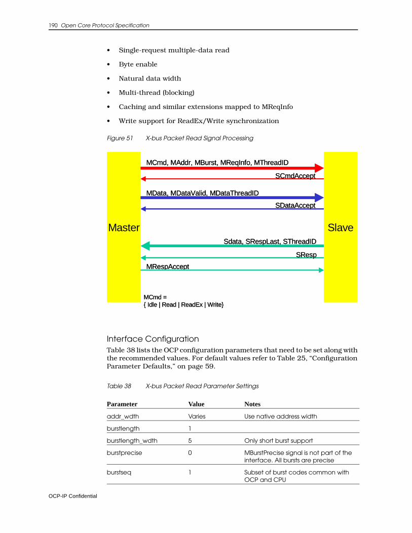
190 Open Core Protocol Specification
• Single-request multiple-data read
• Byte enable
• Natural data width
• Multi-thread (blocking)
• Caching and similar extensions mapped to MReqInfo
• Write support for ReadEx/Write synchronization
Figure 51 X-bus Packet Read Signal Processing
Interface ConfigurationTable 38 lists the OCP configuration parameters that need to be set along with the recommended values. For default values refer to Table 25, “Configuration Parameter Defaults,” on page 59.
Table 38 X-bus Packet Read Parameter Settings
Parameter Value Notes
addr_wdth Varies Use native address width
burstlength 1
burstlength_wdth 5 Only short burst support
burstprecise 0 MBurstPrecise signal is not part of the interface. All bursts are precise
burstseq 1 Subset of burst codes common with OCP and CPU
Master Slave
MCmd, MAddr, MBurst, MReqInfo, MThreadID
Sdata, SRespLast, SThreadID
SCmdAccept
SResp
MCmd ={ Idle | Read | ReadEx | Write}
MRespAccept
MData, MDataValid, MDataThreadID
SDataAccept
Master Slave
MCmd, MAddr, MBurst, MReqInfo, MThreadID
Sdata, SRespLast, SThreadID
SCmdAccept
SResp
MCmd ={ Idle | Read | ReadEx | Write}
MRespAccept
MData, MDataValid, MDataThreadID
SDataAccept
OCP-IP Confidential
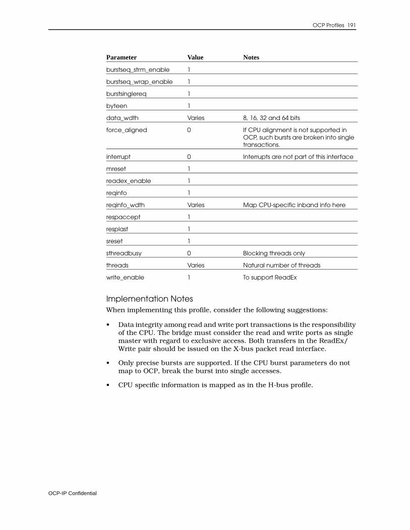
OCP Profiles 191
Implementation NotesWhen implementing this profile, consider the following suggestions:
• Data integrity among read and write port transactions is the responsibility of the CPU. The bridge must consider the read and write ports as single master with regard to exclusive access. Both transfers in the ReadEx/Write pair should be issued on the X-bus packet read interface.
• Only precise bursts are supported. If the CPU burst parameters do not map to OCP, break the burst into single accesses.
• CPU specific information is mapped as in the H-bus profile.
burstseq_strm_enable 1
burstseq_wrap_enable 1
burstsinglereq 1
byteen 1
data_wdth Varies 8, 16, 32 and 64 bits
force_aligned 0 If CPU alignment is not supported in OCP, such bursts are broken into single transactions.
interrupt 0 Interrupts are not part of this interface
mreset 1
readex_enable 1
reqinfo 1
reqinfo_wdth Varies Map CPU-specific inband info here
respaccept 1
resplast 1
sreset 1
sthreadbusy 0 Blocking threads only
threads Varies Natural number of threads
write_enable 1 To support ReadEx
Parameter Value Notes
OCP-IP Confidential

192 Open Core Protocol Specification
OCP-IP Confidential
12 Verification Guidelines
This chapter describes checks (performed by the ocpcheck tool) to determine compliance with the OCP protocol and is intended to help in the development of verification suites and checkers in various verification environments. The checks within this chapter assume that the configuration being tested is valid. For more information about the ocpcheck tool, see the Core Preparation Guide.
Checks need to be applied with varying frequency; cycle-based checks on every cycle, phase-based checks across each phase of an OCP transfer. Transfer-level checks verify correct sequencing among grouped OCP phases. Transaction-level checks verify that protocol requirements for grouped trans-fers are not violated.
Make all OCP checks synchronous with respect to the rising edge of the OCP clock so that signal values are analyzed at the rising edge of the OCP clock. Check any complex hierarchy elements that span multiple cycles from data collected on the rising edge of the clock.
Checks of any sort should not be performed until either MReset_n or SReset_n becomes 0. Checks should also not occur if either signal is 0. The only checks that need not comply with this rule are the checks for X or Z on MReset_n and SReset_n. These checks are performed once either signal transitions to 0. A second exception is the check to see that MReset_n and SReset_n are held to 0 for sixteen cycles.
OCP-IP Confidential
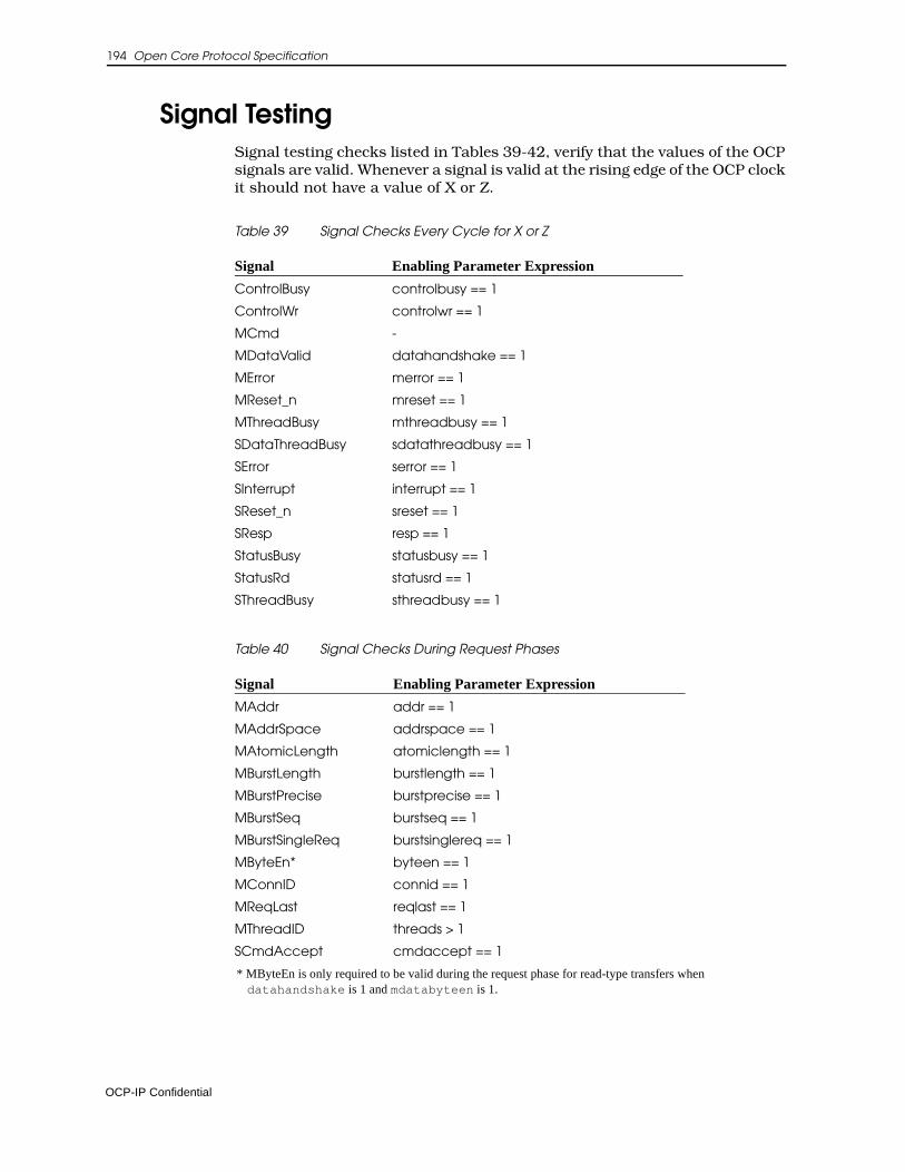
194 Open Core Protocol Specification
Signal TestingSignal testing checks listed in Tables 39-42, verify that the values of the OCP signals are valid. Whenever a signal is valid at the rising edge of the OCP clock it should not have a value of X or Z.
Table 39 Signal Checks Every Cycle for X or Z
Table 40 Signal Checks During Request Phases
* MByteEn is only required to be valid during the request phase for read-type transfers when datahandshake is 1 and mdatabyteen is 1.
Signal Enabling Parameter Expression
ControlBusy controlbusy == 1
ControlWr controlwr == 1
MCmd -
MDataValid datahandshake == 1
MError merror == 1
MReset_n mreset == 1
MThreadBusy mthreadbusy == 1
SDataThreadBusy sdatathreadbusy == 1
SError serror == 1
SInterrupt interrupt == 1
SReset_n sreset == 1
SResp resp == 1
StatusBusy statusbusy == 1
StatusRd statusrd == 1
SThreadBusy sthreadbusy == 1
Signal Enabling Parameter Expression
MAddr addr == 1
MAddrSpace addrspace == 1
MAtomicLength atomiclength == 1
MBurstLength burstlength == 1
MBurstPrecise burstprecise == 1
MBurstSeq burstseq == 1
MBurstSingleReq burstsinglereq == 1
MByteEn* byteen == 1
MConnID connid == 1
MReqLast reqlast == 1
MThreadID threads > 1
SCmdAccept cmdaccept == 1
OCP-IP Confidential
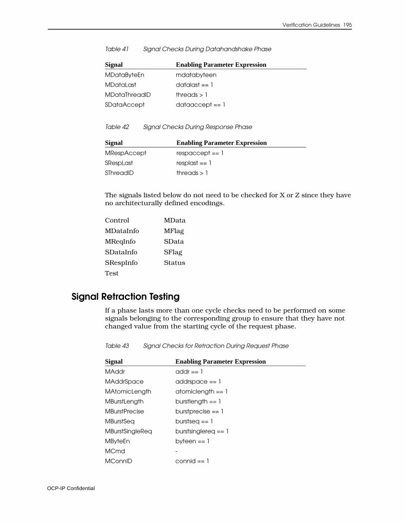
Verification Guidelines 195
Table 41 Signal Checks During Datahandshake Phase
Table 42 Signal Checks During Response Phase
The signals listed below do not need to be checked for X or Z since they have no architecturally defined encodings.
Signal Retraction TestingIf a phase lasts more than one cycle checks need to be performed on some signals belonging to the corresponding group to ensure that they have not changed value from the starting cycle of the request phase.
Table 43 Signal Checks for Retraction During Request Phase
Signal Enabling Parameter Expression
MDataByteEn mdatabyteen
MDataLast datalast == 1
MDataThreadID threads > 1
SDataAccept dataaccept == 1
Signal Enabling Parameter Expression
MRespAccept respaccept == 1
SRespLast resplast == 1
SThreadID threads > 1
Control MData
MDataInfo MFlag
MReqInfo SData
SDataInfo SFlag
SRespInfo Status
Test
Signal Enabling Parameter Expression
MAddr addr == 1
MAddrSpace addrspace == 1
MAtomicLength atomiclength == 1
MBurstLength burstlength == 1
MBurstPrecise burstprecise == 1
MBurstSeq burstseq == 1
MBurstSingleReq burstsinglereq == 1
MByteEn byteen == 1
MCmd -
MConnID connid == 1
OCP-IP Confidential
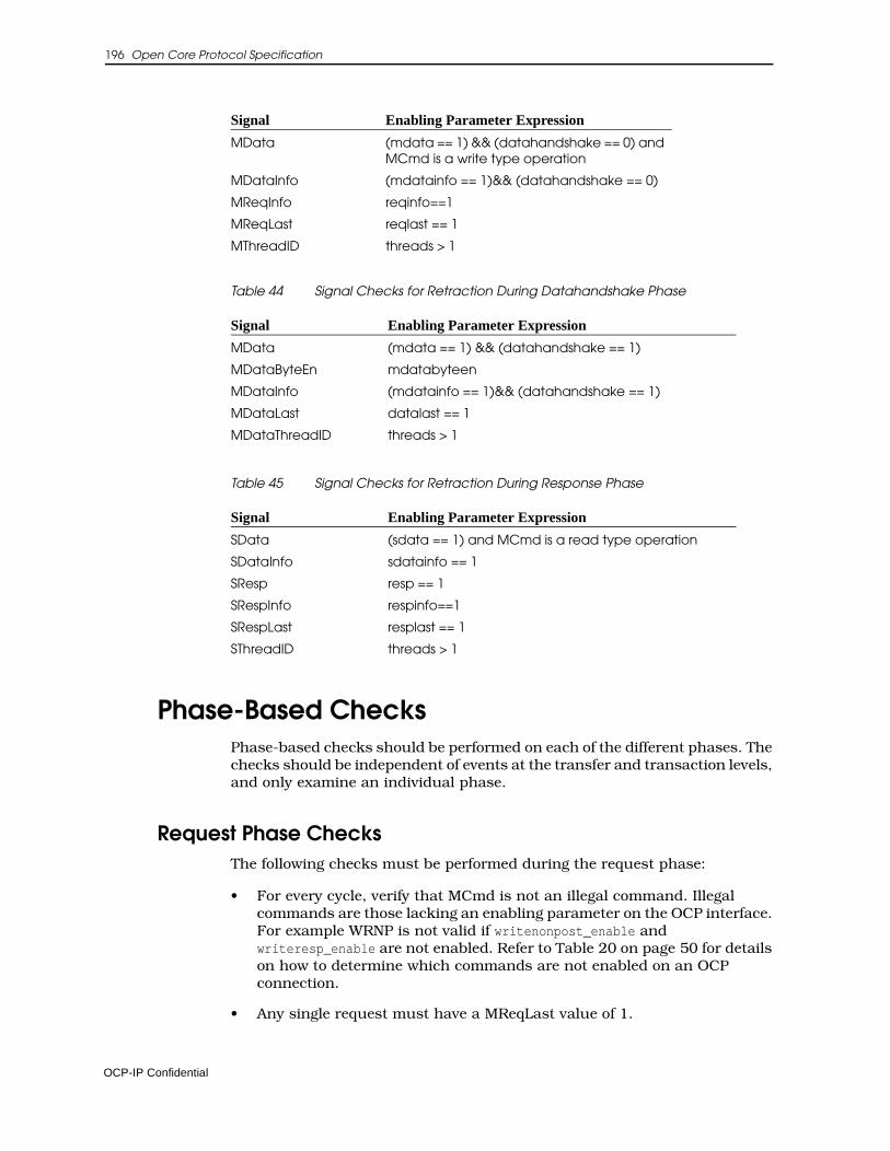
196 Open Core Protocol Specification
Table 44 Signal Checks for Retraction During Datahandshake Phase
Table 45 Signal Checks for Retraction During Response Phase
Phase-Based ChecksPhase-based checks should be performed on each of the different phases. The checks should be independent of events at the transfer and transaction levels, and only examine an individual phase.
Request Phase ChecksThe following checks must be performed during the request phase:
• For every cycle, verify that MCmd is not an illegal command. Illegal commands are those lacking an enabling parameter on the OCP interface. For example WRNP is not valid if writenonpost_enable and writeresp_enable are not enabled. Refer to Table 20 on page 50 for details on how to determine which commands are not enabled on an OCP connection.
• Any single request must have a MReqLast value of 1.
MData (mdata == 1) && (datahandshake == 0) and MCmd is a write type operation
MDataInfo (mdatainfo == 1)&& (datahandshake == 0)
MReqInfo reqinfo==1
MReqLast reqlast == 1
MThreadID threads > 1
Signal Enabling Parameter Expression
MData (mdata == 1) && (datahandshake == 1)
MDataByteEn mdatabyteen
MDataInfo (mdatainfo == 1)&& (datahandshake == 1)
MDataLast datalast == 1
MDataThreadID threads > 1
Signal Enabling Parameter Expression
SData (sdata == 1) and MCmd is a read type operation
SDataInfo sdatainfo == 1
SResp resp == 1
SRespInfo respinfo==1
SRespLast resplast == 1
SThreadID threads > 1
Signal Enabling Parameter Expression
OCP-IP Confidential
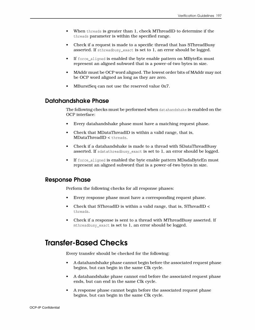
Verification Guidelines 197
• When threads is greater than 1, check MThreadID to determine if the threads parameter is within the specified range.
• Check if a request is made to a specific thread that has SThreadBusy asserted. If sthreadbusy_exact is set to 1, an error should be logged.
• If force_aligned is enabled the byte enable pattern on MByteEn must represent an aligned subword that is a power-of-two bytes in size.
• MAddr must be OCP word aligned. The lowest order bits of MAddr may not be OCP word aligned as long as they are zero.
• MBurstSeq can not use the reserved value 0x7.
Datahandshake PhaseThe following checks must be performed when datahandshake is enabled on the OCP interface:
• Every datahandshake phase must have a matching request phase.
• Check that MDataThreadID is within a valid range, that is, MDataThreadID < threads.
• Check if a datahandshake is made to a thread with SDataThreadBusy asserted. If sdatathreadbusy_exact is set to 1, an error should be logged.
• If force_aligned is enabled the byte enable pattern MDadaByteEn must represent an aligned subword that is a power-of-two bytes in size.
Response PhasePerform the following checks for all response phases:
• Every response phase must have a corresponding request phase.
• Check that SThreadID is within a valid range, that is, SThreadID < threads.
• Check if a response is sent to a thread with MThreadBusy asserted. If mthreadbusy_exact is set to 1, an error should be logged.
Transfer-Based ChecksEvery transfer should be checked for the following:
• A datahandshake phase cannot begin before the associated request phase begins, but can begin in the same Clk cycle.
• A datahandshake phase cannot end before the associated request phase ends, but can end in the same Clk cycle.
• A response phase cannot begin before the associated request phase begins, but can begin in the same Clk cycle.
OCP-IP Confidential
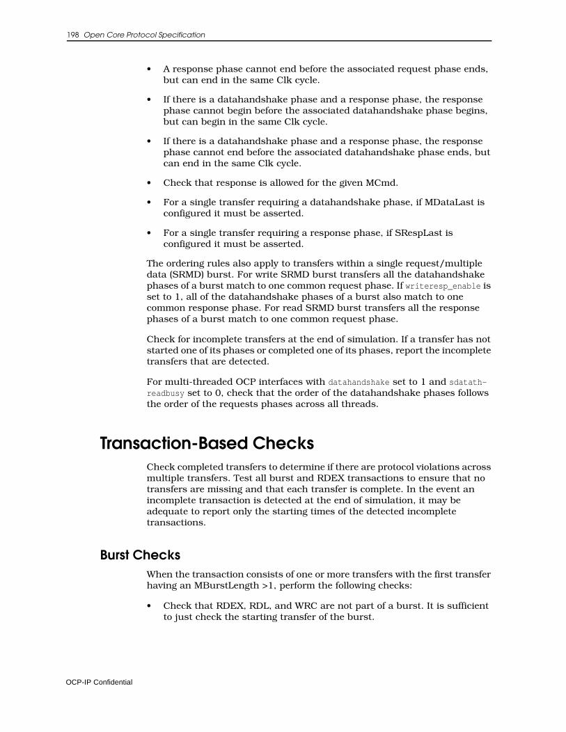
198 Open Core Protocol Specification
• A response phase cannot end before the associated request phase ends, but can end in the same Clk cycle.
• If there is a datahandshake phase and a response phase, the response phase cannot begin before the associated datahandshake phase begins, but can begin in the same Clk cycle.
• If there is a datahandshake phase and a response phase, the response phase cannot end before the associated datahandshake phase ends, but can end in the same Clk cycle.
• Check that response is allowed for the given MCmd.
• For a single transfer requiring a datahandshake phase, if MDataLast is configured it must be asserted.
• For a single transfer requiring a response phase, if SRespLast is configured it must be asserted.
The ordering rules also apply to transfers within a single request/multiple data (SRMD) burst. For write SRMD burst transfers all the datahandshake phases of a burst match to one common request phase. If writeresp_enable is set to 1, all of the datahandshake phases of a burst also match to one common response phase. For read SRMD burst transfers all the response phases of a burst match to one common request phase.
Check for incomplete transfers at the end of simulation. If a transfer has not started one of its phases or completed one of its phases, report the incomplete transfers that are detected.
For multi-threaded OCP interfaces with datahandshake set to 1 and sdatath-readbusy set to 0, check that the order of the datahandshake phases follows the order of the requests phases across all threads.
Transaction-Based ChecksCheck completed transfers to determine if there are protocol violations across multiple transfers. Test all burst and RDEX transactions to ensure that no transfers are missing and that each transfer is complete. In the event an incomplete transaction is detected at the end of simulation, it may be adequate to report only the starting times of the detected incomplete transactions.
Burst ChecksWhen the transaction consists of one or more transfers with the first transfer having an MBurstLength >1, perform the following checks:
• Check that RDEX, RDL, and WRC are not part of a burst. It is sufficient to just check the starting transfer of the burst.
OCP-IP Confidential
Verification Guidelines 199
• MCmd, MConnID, MAddrSpace, MBurstPrecise, MBurstSingleReq, MBurstSeq, MAtomicLength, and MReqInfo must remain constant across all transfers of the burst. This is true for both precise and imprecise bursts.
• When MBurstSingleReq is set to 0, for the last transfer of the burst, MReqLast must be 1. All other burst transfers must have a MReqLast of 0. When MBurstSingleReq is set to 1, MReqLast must be 1.
• MBurstLength must remain constant across all transfers of a precise burst.
• MDataLast should only be 1 for the last transfer of the burst. All other burst transfers must have a MDataLast value of 0.
• For the last transfer of a burst, SRespLast must be 1. All other burst transfers must have a SRespLast value of 0.
• If burstseq_dflt1_enable is 0 the master must not issue DFLT1 bursts. This can be determined by checking the starting transfer of the burst.
• If burstseq_dflt2_enable is 0 the master must not issue DFLT2 bursts. This can be determined by checking the starting transfer of the burst.
• If burstseq_incr_enable is 0 the master must not issue INCR bursts. This can be determined by checking the starting transfer of the burst.
• If burstseq_strm_enable is 0 the master must not issue STRM bursts. This can be determined by checking the starting transfer of the burst.
• If burstseq_unkn_enable is 0 the master must not issue UNKN bursts. This can be determined by checking the starting transfer of the burst.
• If burstseq_wrap_enable is 0 the master must not issue WRAP bursts. This can be determined by checking the starting transfer of the burst.
• If burstseq_xor_enable is 0 the master must not issue XOR bursts. This can be determined by checking the starting transfer of the burst.
• WRAP and XOR burst sequences must only occur with precise bursts.
• WRAP and XOR must always have a power of two burst length. Checking MBurstLength of the first transfer is sufficient for this check.
• Verify the MAddr sequence is correct for XOR bursts.
• For incrementing bursts, when burst_aligned is enabled, the total burst size must be a power of two.
• When burst_aligned is enabled, incrementing bursts must have their starting address aligned with the total burst size.
• When burst_aligned is enabled, incrementing bursts must be issued as precise bursts.
• Each transfer of an incrementing burst must increment MAddr by the OCP word size.
OCP-IP Confidential
200 Open Core Protocol Specification
• For incrementing bursts MAddr must never wrap around the address space of the OCP interface.
• Streaming bursts must have the same MAddr across all transfers of the burst and MByteEn must be constant
• Verify that the address sequence is correct for WRAP bursts.
• If reqdata_together is set to 1, the request and data must arrive together.
• For precise bursts the transfer count must match MBurstLength.
Read Exclusive Transaction CheckPerform the following checks on RDEX transactions:
• On the completion of a ReadEx transfer, check that the next transfer on the same thread is a WR or WRNP to the same address (MAddr and MAddrSpace), and byte enable pattern (MByteEn) as the ReadEx transaction.
• Check that the WR/WRNP following the RDEX has a MBurstLength of 1
Sideband ChecksThe checks in this section apply to the sideband signals.
Reset ChecksThe following checks must be performed on the reset signals:
• If MReset_n is asserted, it must remain asserted for at least 16 cycles.
• If SReset_n is asserted, it must remain asserted for at least 16 cycles.
Control ChecksThe following checks must be performed on the control signals:
• Control must be held steady the first cycle after reset is deasserted.
• The ControlWr signal cannot be asserted in the cycle following a reset.
• The Control signal can not change more than once every other cycle.
• The ControlWr signal must be asserted when the Control signal changes.
• The Control signal may not change if the ControlBusy signal is asserted.
• The ControlWr signal can not remain asserted for two consecutive cycles.
• The ControlWr signal can not be asserted if ControlBusy is active.
OCP-IP Confidential
Verification Guidelines 201
• ControlBusy can only be asserted in a cycle after ControlWr is asserted or reset transitions to inactive.
Status ChecksThe following checks must be performed on the status signals:
• The StatusRd signal is active for no more than one clock cycle.
• The StatusRd signal is not asserted while StatusBusy is asserted.
OCP-IP Confidential

13 Core Performance
To make it easier for the system integrator to choose cores and architect the system, an IP core provider should document a core’s performance character-istics. This chapter supplies a template for a core performance report on page 208, and directions on how to fill out the template.
Report InstructionsTo document the core, you will need to provide the following information:
1. Core name. Identify the core by the name you assigned.
2. Core ID. Specify the precise identification of the core inside the system-on-chip. The information consists of the vendor code, core code, and revision code.
3. Core is/is not process dependent. Specify whether the core is process-dependent or not. This is important for the frequency, area, and power estimates that follow.
If multiple processes are supported, name them here and specify corresponding frequency/area/power numbers separately for each core if they are known.
4. Frequency range for this core. Specify the frequency range that the core can run at. If there are conditions attached, state them clearly.
5. Area. Specify the area that the core occupies. State how the number was derived and be precise about the units used.
6. Power estimate. Specify an estimate of the power that the core consumes. This naturally depends on many factors, including the operations being processed by the core. State all those conditions clearly, and if possible, supply a file of vectors that was used to stimulate the core when the power estimate was made.
OCP-IP Confidential

204 Open Core Protocol Specification
7. Special reset requirements. If the core needs MReset_n/SReset_n asserted for more than the default (16 OCP clock cycles) list the requirement.
8. Number of interfaces.
9. Interface information. For each OCP interface that the core provides, list the name and type.
The remaining sections focus on the characteristics and performance of these OCP interfaces.
• For master OCP interfaces:
a. Issue rate (per OCP cycle for sequences of reads, writes, and interleaved reads/writes). State the maximum issue rate. Specify issue rates for sequences of reads, writes, and interleaved reads and writes.
b. Maximum number of operations outstanding (pipelining support). State the number of outstanding operations that the core can support; is there support for pipelining.
c. If the core has burst support, state how it makes use of bursts, and how the use of bursts affects the issue rates.
d. High level flow-control. If the core makes use of high-level flow control, such as full/empty bits, state what these mechanisms are and how they affect performance.
e. If multiple threads are present, explain the use of threads.
f. Connection ID support. Explain the use and meaning of connection information.
g. Use of side-band signals. For each sideband signal (such as SInterrupt, MFlag) explain the use of the signal.
h. If the OCP interface has any implementation restrictions, they need to be clearly documented.
• For slave OCP interfaces:
a. Unloaded latency for each operation (in OCP cycles). Describe the unloaded latency of each type of operation.
b. Throughput of operations (per OCP cycle for sequences of reads, writes, and interleaved reads/writes). State the maximum throughput of the operations for sequences of reads, writes, and interleaved reads and writes.
c. Maximum number of operations outstanding (pipelining support). State the number of outstanding operations that the core can support, i.e. is there support for pipelining.
d. Burst support and effect on latency and throughput numbers. If the core has burst support, state how it makes use of bursts, and how the use of bursts affects the latency and throughput numbers stated above.
OCP-IP Confidential
Core Performance 205
e. High level flow-control. If the core makes use of high-level flow control, such as full/empty bits, state what these mechanisms are and how they affect performance.
f. If multiple threads are present, explain the use of threads.
g. Connection ID support. Explain the use and meaning of connection information.
h. Use of side-band signals. For each sideband signal (such as SInterrupt, MFlag) explain the use of the signal.
i. If the OCP interface has any implementation restrictions, they need to be clearly documented.
• For every non-OCP interface, you will need to provide all of the same information as for OCP interfaces wherever it is applicable.
OCP-IP Confidential
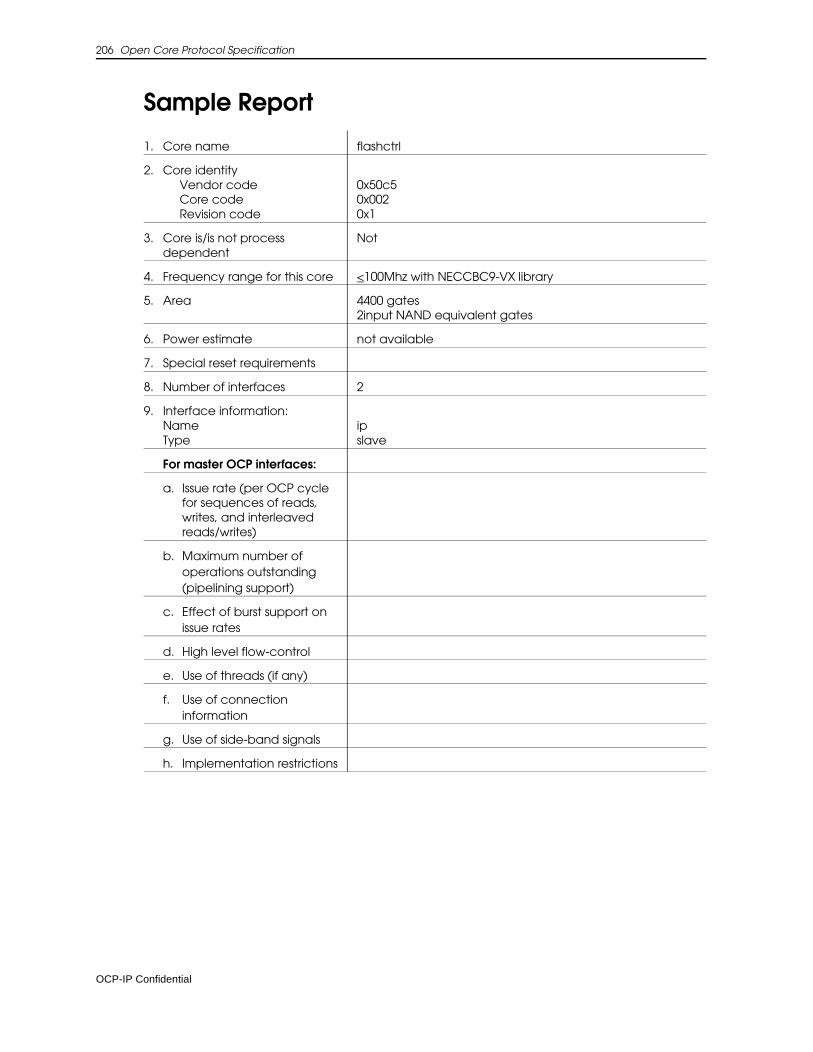
206 Open Core Protocol Specification
Sample Report
1. Core name flashctrl
2. Core identity Vendor codeCore codeRevision code
0x50c50x0020x1
3. Core is/is not process dependent
Not
4. Frequency range for this core <100Mhz with NECCBC9-VX library
5. Area 4400 gates2input NAND equivalent gates
6. Power estimate not available
7. Special reset requirements
8. Number of interfaces 2
9. Interface information:NameType
ipslave
For master OCP interfaces:
a. Issue rate (per OCP cycle for sequences of reads, writes, and interleaved reads/writes)
b. Maximum number of operations outstanding (pipelining support)
c. Effect of burst support on issue rates
d. High level flow-control
e. Use of threads (if any)
f. Use of connection information
g. Use of side-band signals
h. Implementation restrictions
OCP-IP Confidential
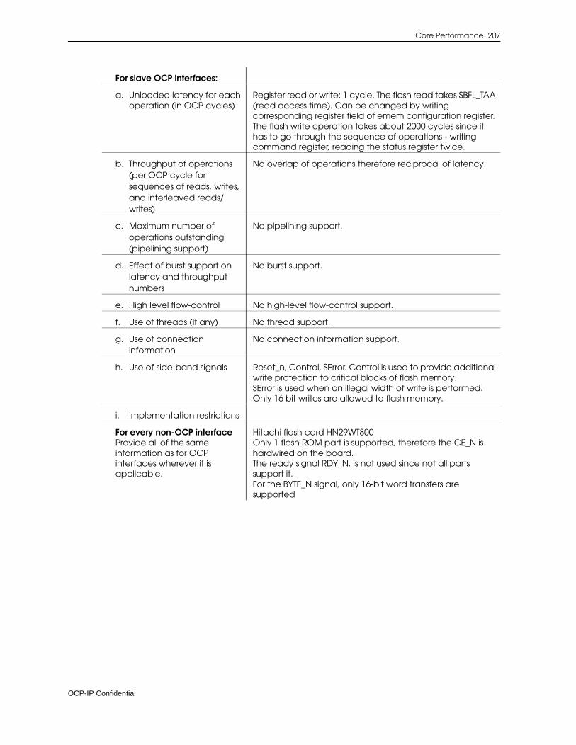
Core Performance 207
For slave OCP interfaces:
a. Unloaded latency for each operation (in OCP cycles)
Register read or write: 1 cycle. The flash read takes SBFL_TAA (read access time). Can be changed by writing corresponding register field of emem configuration register.The flash write operation takes about 2000 cycles since it has to go through the sequence of operations - writing command register, reading the status register twice.
b. Throughput of operations (per OCP cycle for sequences of reads, writes, and interleaved reads/writes)
No overlap of operations therefore reciprocal of latency.
c. Maximum number of operations outstanding (pipelining support)
No pipelining support.
d. Effect of burst support on latency and throughput numbers
No burst support.
e. High level flow-control No high-level flow-control support.
f. Use of threads (if any) No thread support.
g. Use of connection information
No connection information support.
h. Use of side-band signals Reset_n, Control, SError. Control is used to provide additional write protection to critical blocks of flash memory.SError is used when an illegal width of write is performed. Only 16 bit writes are allowed to flash memory.
i. Implementation restrictions
For every non-OCP interfaceProvide all of the same information as for OCP interfaces wherever it is applicable.
Hitachi flash card HN29WT800Only 1 flash ROM part is supported, therefore the CE_N is hardwired on the board.The ready signal RDY_N, is not used since not all parts support it.For the BYTE_N signal, only 16-bit word transfers are supported
OCP-IP Confidential

208 Open Core Protocol Specification
Performance Report TemplateUse the following template to document a core.
1. Core name
2. Core identity Vendor codeCore codeRevision code
3. Core is/is not process dependent
4. Frequency range for this core
5. Area
6. Power estimate
7. Special reset requirements
8. Number of interfaces
9. Interface information:NameType
For master OCP interfaces:
a. Issue rate (per OCP cycle for sequences of reads, writes, and interleaved reads/writes)
b. Maximum number of operations outstanding (pipelining support)
c. Effect of burst support on latency and throughput numbers
d. High level flow-control
e. Use of threads (if any)
f. Use of connection information
g. Use of side-band signals
h. Implementation restrictions
OCP-IP Confidential

Core Performance 209
For slave OCP interfaces:
a. Unloaded latency for each operation (in OCP cycles)
b. Throughput of operations (per OCP cycle for sequences of reads, writes, and interleaved reads/writes)
c. Maximum number of operations outstanding (pipelining support)
d. Effect of burst support on latency and throughput numbers
e. High level flow-control
f. Use of threads (if any)
g. Use of connection information
h. Use of side-band signals
i. Implementation restrictions
For every non-OCP interfaceProvide all of the same information as for OCP interfaces wherever it is applicable.
OCP-IP Confidential

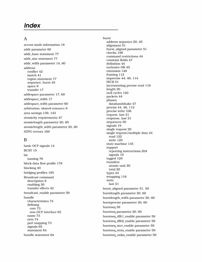
Index
Aaccess mode information 18
addr parameter 60
addr_base statement 77
addr_size statement 77
addr_wdth parameter 14, 60
addressconflict 42match 41region statement 77sequence, burst 45space 9transfer 17
addrspace parameter 17, 60
addrspace_wdth 17
addrspace_wdth parameter 60
arbitration, shared resource 8
area savings 139, 143
atomicity requirements 47
atomiclength parameter 20, 60
atomiclength_wdth parameter 20, 60
ATPG vectors 169
Bbasic OCP signals 14
BCST 15
bitnaming 76
block data flow profile 178
blocking 40
bridging profiles 185
Broadcast commanddescription 8enabling 50transfer effects 42
broadcast_enable parameter 59
bundlecharacteristics 74defining
core 73non-OCP interface 63
name 73nets 74port mapping 73signals 65statement 64
bundle statement 64
burstaddress sequence 20, 45alignment 51burst_aligned parameter 51checks 198command restrictions 44constant fields 47definition 44exclusive OR 45extension 149framing 112imprecise 44, 46, 114INCR 51incrementing precise read 118length 20null cycles 120packets 44phases
datahandshake 47precise 44, 46, 112precise write 106request, last 21response, last 21sequences 50signals 19single request 20single request/multiple data 44
read 122write 125
state machine 145support
reporting instructions 204signals 19
tagged 129transfers
atomic unit 20total 20
types 44wrapping 116write
last 21
burst_aligned parameter 51, 59
burstlength parameter 20, 60
burstlength_wdth parameter 20, 60
burstprecise parameter 20, 60
burstseq 59
burstseq parameter 20, 60
burstseq_dflt1_enable parameter 59
burstseq_dflt2_enable parameter 59
burstseq_incr_enable parameter 59
burstseq_strm_enable parameter 59
burstseq_unkn_enable parameter 59

212 Open Core Protocol Specification
burstseq_wrap_enable parameter 59
burstseq_xor_enable parameter 59
burstsinglereq parameter 21, 60
busindependence 8of signals 65wrapper interface module 2
byte enabledata width conversion 46field 17MByteEn signal 17pattern 47supported patterns 51write 17
byteen parameter 17, 60
Cc2qtime
port constraints 89timing 82
c2qtimemin 89
cacheable storage attributes 18
capacitancewireload 91wireloaddelay 91
capacitive load 83
cell library name 83
chipparam variable 87
Clk signalfunction 14summary 28
ClkByp signalfunction 26summary 30test extensions 169timing 41
clkctrl_enable parameter 27, 62
clockbypass signal 27control test extensions 169gated test 27non-OCP 88portname 89signal 14test 27
clockName 88
clockname field 89
clockperiod variable 86
cmdaccept parameter 15, 60
combinationaldependencies 35, 173Mealy state machine 143
paths 85, 94slave state machine 144
commandencoding 15limiting 15request types 15
commandsbasic 8extensions 8mnemonic 15required 55
concurrency 155
configurable interfaces 75
connectiondescription 160identifier
definition 160field 22support 204, 205transfer handling 49uses 10
transfers 49
connid parameter 22, 60
connid_wdth parameter 22, 60
controlevent signal 26field 26information
specifying 25timing 41
parameter 25, 62timing 41
Control signalfunction 24summary 29timing 41
control_wdth parameter 25, 62
controlbusy parameter 26, 62
ControlBusy signalfunction 24summary 29timing 41
controlwr parameter 26, 62
ControlWr signal 41function 24summary 29
corearea 88, 203code 71compliance 3control
busy 26event 26information 25
documentation 203
Index 213
documentation template 208endianness 53frequency range 203ID 203interconnecting 84interface
defining 73endianness 44timing parameters 82
interoperability 55name 203power consumption 203process dependent 203revision 71RTL configuration file 69status
busy 26event 26information 26
synthesis configuration filedefining 81
tie-off constants 58timing 81, 171
core_id statement 70
core_name 69
core_stmt 69
Ddata byte parity 17, 18
data width conversion 46
data_wdth parameter 15, 16, 60
dataaccept parameter 16, 60
dataflow signalsdefinitions 14naming 14timing 36
datahandshakeextension 123intra-phase output 158parameter 15phase
active 37checks 197order 38
sequence 140signal group 34
datahandshake parameter 54, 59
datalast parameter 21, 60
ddr_space statement 77
debug and test interface 27, 169
DFLT1 burst sequence 45, 51
DFLT2 burst sequence 45, 51
direction statement 65
driver strength 83
drivingcellpin parametertiming requirements 83values 89
DVA 16
DVA response 16, 41
Eendian parameter 59
endiannessattributes 53concepts 43
ERR response 16
errorcorrection code 17, 18master 24report mechanisms 11signal 24slave 25
exclusive OR bursts 45
extended OCP signals 16, 146
FFAIL response 16, 41
false path constraints 85, 94
falsepath parameter 85, 94
fanoutmaximum 90
FIFOfull 19
flagscore-specific 24master 24slave 25
flow-control 204, 205
force_aligned parameter 51, 59
HH-bus profile 185
high-frequency design 140
hold timechecking 82
holdtimedescription 90timing 82
Iicon statement 70
implementation restrictions 204, 205
imprecise burst 46

214 Open Core Protocol Specification
INCR burst sequence 45, 51
inout ports 91, 92
inputload 83port syntax 91signal timing 82
instancesize 88
interfacecharacteristics 204clock control 27compatibility 55configurable 75configuration file 63core RTL description 69debug and test 27endianness 44location 76multiple 73parameters 75scan 27statement 73type statement 74types 65
interface_types statement 65
interfaceparam variable 87
internalscan techniques 169
interoperability rules 55
interruptparameter 25processing 10signal 24slave 25
interrupt parameter 62
Jjtag_enable parameter 27, 62
jtagtrst_enable 28
jtagtrst_enable parameter 62
Llatency
sensitive master 144
level0 timing 171, 172
level1 timing 171, 172
level2 timing 171, 172
loadcellpindescription 90timing 83
loads parameterdescription 90
timing 83
location statement 76
longest path 89
MMAddr signal
function 14summary 28
MAddrSpace signalfunction 16summary 28
mastererror 24flags 24interface documentation 204reset 40response accept 15signal compatibility 55slave interaction 156thread busy 23
MAtomicLength signalatomicity 47function 19summary 29
maxdelay parameterdescription 94timing 85
maxfanout variable 90
MBurstLength signalburst lengths 46function 19summary 29
MBurstPrecise signalfunction 19summary 29
MBurstSeq signalencoding 20function 19summary 29
MBurstSingleReq signalconditions 47function 19summary 29
MBurstSinqleReq signaltransfer phases 37
MByteEn signalfunction 16summary 28
MCmd signalfunction 14summary 28
MConnID signalfunction 22summary 29

Index 215
mdata parameter 15, 60
MData signaldata valid 15description 14request phase 140summary 28
mdatabyteen parameter 17, 60
MDataByteEn signalfunction 16phases 36summary 28
mdatainfo parameter 17, 60
MDataInfo signalfunction 16summary 28
mdatainfo_wdth parameter 17, 61
mdatainfobyte_wdth parameter 61
MDataLast signalfunction 19phases 48summary 29
MDataTagID signalflow 48function 21summary 29
MDataThreadID signaldatahandshake 155function 22summary 29
MDataValid signaldatahandshake 140function 14summary 28timing 140
merror parameter 24, 62
MError signalsummary 29
mflag parameter 24, 62
MFlag signalfunction 24summary 29
mflag_wdth parameter 24, 62
MReqInfo signalfunction 16summary 28
MReqLast signalfunction 19phases 48summary 29
mreset parameter 24, 62
MReset_n signalfunction 24required cycles 40
summary 29timing 40
MRespAccept signaldefinition 14response phase 139response phase output 158saving area 139summary 28
MTagID signalflow 48function 21summary 29
MTagInOrder signalfunction 21summary 29
mthreadbusy parameter 23, 61
MThreadBusy signaldefinition 22information 49intra-phase output 157semantics 39summary 29timing cycle 39
mthreadbusy_exact parameter 39, 52, 59
MThreadID signalfunction 22summary 29
multi-threadedinterface 40
Nnets
bit naming 76characterizing 65redirection 74statement 65
NULL response 16, 120
Oout-of-band information 24
outputport syntax 92signal timing 82
Ppackets 44
param variable 87
parameter summary 28
partial word transfer 43
pathlongest 89shortest 89

216 Open Core Protocol Specification
phaseinteroperability 56intra-phase 156options 54ordering
between transfers 38request 138within transfer 38
protocol 36timing 138transfer 37
physical design parameters 83
pinlevel timing 82
pipelinedecoupling request phase 149request/response protocol 139support 204transfer 145without MRespAccept 139write data, slave 16
pipelined access 178
point-to-point signals 8
portconstraint variables 89delay 94inout 91, 92input, syntax 91mapping 73module names 75output, syntax 92renaming 74statement 74timing constraints 81
posted writemodel 37timing diagram 103
powerconsumption estimates 203
precise burst 46
prefix command 75
profilesbenefits 175block data flow 178bridging 185H-bus 185register access 183sequential undefined length data flow 181types 177X-bus packet read 189X-bus packet write 187
programmable register interfaces 183
proprietary statement 77
protocolinteroperability 55
phasesmapping 36order 38rules 36
RRDEX 15
rdlwrc_enable parameter 59
readburst wrapping 116data field 16imprecise burst 114incrementing precise burst 118information 18non-pipelined timing diagram 107optimizing access 139out-of-order completion 131
tagged 127, 129precise burst 112single request/multiple data 122tagged 127, 129threaded 131timing diagram 100
Read commandenabling 50transfer effects 42
read_enable parameter 59
ReadEx commandburst restrictions 44checks 200enabling 50transfer effects 42
readex_enable parameter 59
ReadLinked commandburst restrictions 44enabling 50encoding 15mnemonic 15transfer effects 42
reference_port statement 74
registeraccess profile 183
reqdata_together parameter 54, 59, 125
reqinfo parameter 18, 61
reqinfo_wdth parameter 18, 61
reqlast parameter 21, 61
requestdelays 102flow-control mechanism 101handshake 101information 18interleaving 47last 47last in a burst 21

Index 217
order 22phase
checks 196intra-phase 157order 38outputs 138, 157signal group 36timing 138transfer ordering 38worst-case combinational path 157
pipelined 109signals
active 36group 34
tag identifier 22thread identifier 23
resetphases 40signal 24special requirements 204state 40timing 136
resistancewireload 91wireloaddelay 91
resp parameter 16, 61
respaccept parameter 15, 61
respinfo parameter 19, 61
respinfo_wdth parameter 19, 61
resplast parameter 21, 61
responseaccept 15accept extension 110delays 102encoding 16field 16information 19last in a burst 21mnemonics 16null cycle 120order 22phase
active 36checks 197intra-phase 157order 38slave 158timing 139
pipelined 109required types 55signal group 34tag identifier 22thread identifier 23
revision_code 71
rootclockperiod variable 87
RTL
proprietary extenstions 77
Sscan
clock 169control 169data
in 27out 27
interface signals 27mode control 27Scanctrl signal 27Scanin signal 27Scanout signal 27test environments 169test mode 169
Scanctrl signalfunction 26summary 30uses 169
scanctrl_wdth parameter 27, 62
Scanin signalfunction 26summary 30timing 41
Scanout signalfunction 26summary 30timing 41
scanport parameter 62
scanport_wdth parameter 27, 62
SCmdAccept signaldefinition 14request phase 138request phase output 157summary 28
sdata parameter 16, 61
SData signalfunction 14summary 28
SDataAccept signaldatahandshake 140function 14summary 28
sdatainfo parameter 18, 61
SDataInfo signalfunction 16summary 28
sdatainfo_wdth parameter 18, 61
sdatainfobyte_wdth parameter 61
sdatathreadbusy parameter 23, 61
SDataThreadBusy signalfunction 22

218 Open Core Protocol Specification
semantics 39summary 29timing cycle 39
SDataThreadbusy signalinformation 49
sdatathreadbusy_exact parameter 39, 59
sequential undefined length data flow profile 181
serror parameter 25, 62
SError signalfunction 24summary 29
setuptimedescription 90timing 82
sflag parameter 25, 62
SFlag signalfunction 24summary 29
sflag_wdth parameter 25, 62
shared resource arbitration 8
shortest path 89
sideband signalsdefinitions 24timing 40, 167
signalattribute list 75basic OCP 14configuration 28dataflow 14direction 31driver strength 83extensions
simple 16thread 21, 22
groupdivision 34mapping 36
interface interoperability 57ordering 156requirements 55sideband 24test 26tie-off 57, 75
rules 57tie-off values 28timing
input 82output 82requirements 36restrictions 156
ungrouped 39width 76width mismatch 57
SInterrupt signalfunction 24
summary 29
slavecombinational paths 157error 25flag
description 25interrupt 25optimizing 155pipelined write data 16reset 40response field 16response phase 158signal compatibility 55successful transfer 41thread busy 23transfer accept 15write
accept 16thread busy 23
sreset parameter 25, 62
SReset_n signalfunction 24required cycles 40summary 29timing 40
SResp signalfunction 14summary 28
SRespInfo signalfunction 16summary 28
SRespLast signalfunction 19phases 48summary 29
STagID signalflow 48function 21summary 29
STagInOrder signalfunction 21summary 29
state machinecombinational
master 143Mealy 143slave 144
diagrams 138multi-threaded behavior 155sequential master 140sequential slave 142
statusbusy 26core 26event 26information

Index 219
response 19signals 26
parameter 26timing 41
status parameter 62
Status signalfunction 24summary 29
status_wdth parameter 26, 62
statusbusy parameter 26, 62
StatusBusy signalfunction 24summary 29timing 41
statusrd parameter 26, 62
StatusRd signalfunction 24summary 29timing 41
sthreadbusy parameter 23, 61
SThreadBusy signalfunction 22information 49semantics 39slave request phase 157summary 29timing cycle 39
sthreadbusy_exact parameter 39, 52, 59, 133
SThreadID signalfunction 22summary 29
STRM burst sequence 45, 51
subnet statement 76
synchronoushandshaking signals 3interface 8reset
master 24slave 25
systeminitiator 2target 2
Ttag
burst handling 129flow 48identifier
binary-encoded value 21interleaving 48ordering 48read handling 127
taginorder parameter 22, 61
tags parameter 61
TCK signalfunction 26summary 30
TDI signalfunction 26summary 30
TDO signalfunction 26summary 30
testclock 27clock control extensions 169data
in 27out 27
logic reset 28mode 28signals
definitions 26timing 40, 41
TestClk signalfunction 26summary 30timing 41
threadarbitration 135blocking 40, 133busy
hint 133master 23signals 49slave 23
busy signals 155description 155end-to-end identification 49identifier
binary-encoded value 23definition 160request 23response 23uses 49
mapping 49multiple
concurrent activity 49non-blocking 52
ordering 10signal extensions 22state machine implementation 155transfer order 155
threads parameter 23, 61
throughputdocumenting 204maximum 138peak data 144
timing
220 Open Core Protocol Specification
categoriesdefinitions 171level0 172level1 172level2 172
combinational path 35combinational paths 85constraints
ports 81core 81
connecting 84interface parameters 82
dataflow signals 36diagrams 99max delay 85parameters 89pin-level 82pins 83sideband signals 40signals 36, 156test signals 40
TMS signalfunction 26summary 30
transferaccept 15address 14address region 17assigning 49burst
linking 44byte enable 17command 15concurrent activity 49connection ID 22data widths 9effects of commands 42efficiency 9, 46endianness 44order 10, 38out-of-order 49phases 37pipelining 9successful 41type 15validity checks 197
TRST_N signalfunction 26summary 30
type statement 65
UUNKN burst sequence 45, 51
Vvendor code 71
version 88statement 64, 70
VHDLports 65signals 65
vhdl_type command 65
Virtual Socket Interface Alliance 1
Wwidth
data 9interoperability 57mismatch 57
wireloadcapacitancedescription 91See also wireloaddelaytiming 83
wireloaddelaydescription 91timing 83
wireloadresistancedescription 91timing 83
wordcorresponding bytes 17packing 46padding 46partial 43power-of-2 15size 9, 14stripping 46transfer 9, 43
worstcasedelay 88
WRAP burst sequence 45, 51
wrapper interface modules 2
writebyte enables 17completion model 43data
burst 21extra information 17master to slave 15slave accept 16tag ID 21thread ID 23valid 15
nonpostenabling 54phases 37semantics 43timing diagram 105
postedphases 37semantics 43
precise burst 106
Index 221
response enabled 103responses 54single request, multiple data 125timing diagram 100
Write commandburst restrictions 44enabling 50transfer effects 42
write_enable parameter 59
WriteConditional commandburst restrictions 44enabling 50encoding 15mnemonic 15transfer effects 42
WriteNonPost commandburst restrictions 44
enabling 50encoding 15mnemonic 15posting options 43semantics 8transfer effects 42
writenonpost_enable parameter 59
writeresp_enable parameter 54, 59
XX-bus packet
read profile 189write profile 187
XOR address sequence 45
XOR burst sequence 51


OCP-IP Association5440 SW Westgate Drive, Suite 217Portland, OR 97221Ph: 503-291-2560Fax: [email protected]
Part Number: 161-000125-0003