Embed Size (px)
Citation preview

OPEN ACC ESS
1 Sidra Medical and Research Center,P.O. Box 26999, Doha, Qatar
2 Mechanical Engineering and MaterialScience Department, Military Instituteof Engineering (IME), Rio de Janeiro,RJ, Brazil
3 Lodz University of Technology, Fac-ulty of Material Technologies and Tex-tile Design, Department of Materialand Commodity Sciences and TextileMetrology, ul. Zeromskiego 116, 90-924, Lodz, Poland
4 Institute of Security Technologies‘‘Moratex’’ 3 M, Sk™odowskiej-CurieStreet 90-505 Lodz, Poland
5 Imperial College of Science and Tech-nology, London, UK*Email: [email protected]
http://dx.doi.org/10.21542/gcsp.2016.31
Submitted: 3 July 2016Accepted: 12 September 2016c� 2016 The Author(s), licenseeMagdi Yacoub Institute. This is anopen access article distributed un-der the terms of the Creative Com-mons Attribution license CC BY-4.0,which permits unrestricted use, dis-tribution and reproduction in anymedium, provided the original workis properly cited.
Cite this article as: Liberski A, Ayad N, Wojciechowska D, Zieli´ska D, Struszczyk MH, Latif N,Yacoub M. Knitting for heart valve tissue engineering, Global Cardiology Science and Practice2016:31 http://dx.doi.org/10.21542/gcsp.2016.31
Review article
Knitting for heart valve tissueengineeringAlbert Liberski1*, Nadia Ayad2, Dorota Wojciechowska3, Dorota Zieli´ska4,Marcin H. Struszczyk4, Najma Latif5, Magdi Yacoub1
ABSTRACTKnitting is a versatile technology which offers a large portfolio of products and solutions ofinterest in heart valve (HV) tissue engineering (TE). One of the main advantages of knittingis its ability to construct complex shapes and structures by precisely assembling the yarns inthe desired position. With this in mind, knitting could be employed to construct a HV scaffoldthat closely resembles the authentic valve. This has the potential to reproduce the anisotropicstructure that is characteristic of the heart valve with the yarns, in particular the 3-layeredarchitecture of the leaflets. These yarns can provide oriented growth of cells lengthwise andconsequently enable the deposition of extracellular matrix (ECM) proteins in an oriented manner.This technique, therefore, has a potential to provide a functional knitted scaffold, but to achievethat textile engineers need to gain a basic understanding of structural and mechanical aspectsof the heart valve and in addition, tissue engineers must acquire the knowledge of tools andcapacities that are essential in knitting technology. The aim of this review is to provide a platformto consolidate these two fields as well as to enable an efficient communication and cooperationamong these two research areas.

Page 2 of 33Liberski et al. GCSP 2016:31
GENERAL CHARACTERISTIC OF AORTIC HEART VALVE AND CONCEPT OF SMARTSCAFFOLDThe aortic heart valve (AHV) is responsible for the unidirectional flow of blood out of theleft ventricle, preservation of myocardial function and control of the coronary blood flow1.It closes and opens over 100,000 times a day and will function normally over the lifetimeof a human being2. During this period, it is exposed to shear stress, bending forces, aswell as strain and loading forces that are a result of its hemodynamic environment.
As a living, dynamic organ, it can adapt to its complex biomechanical and mechanicalenvironment through passive and active communication between its constituent parts(see Figure 1)3. An example of passive communication is the influence of the shapesof the sinuses on forming the vortices that are important for valve closure and formaintaining coronary flow during systole. Active communication occurs when structuresin each part of the valve (cusp, annulus, sinus, sinotubular junction) change shape, sizeand stiffness during specific parts of the cardiac cycle1. Such changes guarantee optimalejection of blood from the left ventricle, valve opening and closure, adequate coronaryperfusion as well as cooptation of the leaflets to prevent blood backflow into the leftventricle. This highlights the importance of using tissue engineering to develop heartvalve substitutes that contain living cells and have the ability to assume the complexfunctions of the native valve.
Figure 1. The basic structural/functional aspects of the heart valve (HV). Schematics of the 2Dposition of the four valves on valvular basal plane of the heart where P: pulmonary valve, AO: aortic valve,M: mitral valve, and T: tricuspid valve (a-i), porcine pulmonary heart valve (a-ii), decellularized porcineaortic heart valve (a-iii). The leaflet consists of three distinguishable layers: fibrosa, spongiosa andventricularis (b). Each layer contains specifically oriented fibers, red arrow indicates circumferentiallyoriented fibers of collagen, blue arrow indicates radially oriented fibers of elastin (c).The types (collagen,fibronectin, elastin and others) and arrangement of fibers are responsible for the function of the valve(opening & closing) (d, e). The fibrosa layer is a continuation of aorta and ventricularis is a continuationof the ventricular chamber. (f) The view of sheep aortic valve from ventricular side, after dissecting theheart (g). The leaflets contain glycosaminoglycans (GAGs, mainly in spongiosa, blue color), which worksas a lubricant between layers and a shock absorber (h). The hinge area (in-between the arrows) histologyhighlights the importance of fiber arrangement (I). The cells are housed and maintained in a highlyorganized network of fibers. Reprinted with permission from4.

Page 3 of 33Liberski et al. GCSP 2016:31
The ideal smart scaffold should be non-immunogenic, resorbable and capable ofattracting, housing and instructing cells to produce a particular phenotype5. It shouldalso reproduce the performance and mechanical properties of the native valve, both inthe short and long term.
Therefore, the smart scaffold is and for some time will be, the best option fordeveloping a clinically relevant Tissue Engineered Heart Valve (TEHV) as it enables theremodeling of the construct with the patients’ cells and decreases greatly the possibilityof a detrimental immune response5,6.
The main types of HV scaffolds currently being considered can be divided in twocategories, namely, biological scaffolds and scaffolds based on synthetic polymers. Thefirst category includes decellularised valves and whole organs7, decellularised non crosslinked ECM6, amniotic membrane8 or scaffolds made out of alginate manufactured fromsea weed9. The second type of intelligent scaffolds are made out of synthetic polymers10,including polyglycolic acid (PGA)11, poly (L-lactic acid) (PLL)12, copolymer blend PLGA13,Poly-⇠-caprolactone (PCL) and many others14. These synthetic polymers can also beenhanced with antibodies15,16, peptides17,18, aptamers19 and enzymes20 in a way thatenables the scaffold to attract and instruct host cells, either from blood or surroundingtissue and induce them to differentiate to a tissue specific phenotype.
Using current state-of-the-art technology, it is most reasonable to focus on combining‘‘the best elements’’ of the available strategies by constructing a textile-based scaffoldwith the required functionality and characteristics (Figure 2). The logic behind such anapplication of textile technologies is to utilize its advantages that have already beenshown in the wide use of textile medical grafts in clinical practice. One major advantageof textile techniques is their utility in reproducing the anisotropic properties of thevalve21,22.
Figure 2. Geometry of the native (top panel) HV, and intelligent scaffold (bottom panel). Toppanel was reprinted with permission from2.

Page 4 of 33Liberski et al. GCSP 2016:31
Figure 3. Basic patterns of weft (A1) and warp (B1) knitting. Horizontally aligned yarns, fedcrosswise along the fabric (A2). Parallel yarns lengthwise zigzag along the fabric, each loop securing aloop of a neighboring strand from the previous row (B2). Courses and wales are indicated on both A2 andB2. A1 and B1 were reprinted with permission from24, and B2 was reprinted with permission from23.
BASICS OF KNITTING AND ITS APPLICATIONSKnitting is the process of manufacturing fabrics of interlooped yarns using hookedneedles. The basic elements of the knitted fabrics are the loops. The loops can be closelyor loosely constructed allowing them to be stretched in any direction, even if the yarnitself has low elasticity23.
The fabric can be characterized by the number of courses and wales per cm2. Courseis a line of loops in the horizontal direction and wale is a line of loops in the vertical(Figure 3A2 and 3B2). A knitted fabric having more courses will be rigid and stable inlength while a fabric with more wales will be rigid and stable in width.
There are two basic systems of knitting; the weft and warp knitting (Figure 3). In weftknitting, the yarns come from the horizontal direction, while in warp knitting the yarnscome from the vertical direction. Each horizontal course in weft and vertical in warpknitting can be individually chosen (see Figures 3 and 5).
It is worth noting that weft knitting is useful for generating coherent objectsstretchable in all directions with various choices of pattern, while warp knitting is moresuitable for open net-like, branched structures with programmable directional elasticity.Therefore, for HVTE, warp knitting may be the technique of choice for leaflets, whileweft knitting may be more useful to make a scaffold for sinus of Valsalva (see Figure 2).Additionally, because the nature of warp-knitted loops is more knot-like, the warp-knitted

Page 5 of 33Liberski et al. GCSP 2016:31
Figure 4. Examples of automated knitters. Flat-bed (A) and circular (B) knitting machines. Reprintedwith permission from25,26.
Figure 5. The popular types of weft knitting. Single jersey, face (A1) and back side (A2). Purl stitch,face (B1) and back side (B2). Rib stitch (C) and interlock stiches (D). Examples of links-links patterns (E)and (F). Reprinted with permission from31.
fabrics are more resistant to ripping. This particular aspect makes them more usable formedical textiles applications.
Usually, the weft knitting is performed by the so-called circular knitter machines, whilewarp knitting by flat knitting machines (Figure 4). Both types of machines are capableof fabricating tubular and even seamless garments. This is interesting from the point ofview of HVTE, as the aortic root is a tubular object with a complex geometry (sinuses andleaflets, see Figures 1 and 2).
The most prevalent method of knitting 3D garments is to knit the bi-dimensionalfabrics first followed by post-processing, e.g. by stitching to form the final geometry ofthe product. Currently, there is a strong trend in the direction of seamless garments(Figure 9)27. For that purpose, both weft and warp knitting could be used, however theadvantage of warp knitting is that it can deliver hosiery (Figure 9E) or jackets with sleevesin one run while in weft knitting, sleeves and legs need to be attached separately.
Indeed, the seaming process makes fabrication more difficult to produce and moreexpensive. Nevertheless, the seaming methods are currently very precise and efficient,hence the necessity of seaming does not disqualify weft-knitting as a method to deliver

Page 6 of 33Liberski et al. GCSP 2016:31
complex 3D geometries such as a HV scaffold. Therefore, a compromise betweencomplexity of process and required geometry of design should be made.
In principle, when using unconventional yarns (bioresorbable polymers for example)for fast prototyping, weft knitting is more advantageous since it requires, in its basicsetting, only one cone of yarn, while warp knitting demands that each needle needs tohave its own yarn. Thus, for warp knitting, a large number of cones/bobbins must bedelivered to the knitting facility. As an alternative, the cone could be split, but this is acostly and a technologically advanced operation.
Table 1 outlines a summary of the differences between warp and weft knitting as wellas the importance of the characteristics of each process for HVTE.
Detailed classifications of knitting are presented elsewhere23,28,29 and only a fewexamples are shown on Figures 3 and 5. The most popular types of warp knitting includetricot, Raschel (see Figure 4) and stitch-bonding and for weft, these are single jersey, purl,rib and interlock types of stitches (see Figure 5)23.
From the perspective of HV scaffold construction, a very important characteristic ofknitted fabrics is that they frequently have two distinguishable sides (compare Figure 5A1to 5A2, showing two sides of same fabric sheet) varying in term of texture and properties.This needs to be considered when designing the scaffold as texture may affect its bloodcompatibility30. The difference in properties of each side will often depend on the type ofknitting chosen. For example, interlock stitch will provide a rough surface while a surfaceof velvet with closed loops will be very smooth.
Another important specification of knitting is related to its scaffold coding capacities.The coding concerns the possibility of involving a specific yarn in a specific place ofthe construct. This provides additional precision that could be used to control the typeof surface on which the cells are seeded and manipulate the cells interacting with thescaffold. Jacquard knitting (Figure 6) is one of these techniques that can create a hybridstructure consisting of several types of yarns capable of precisely controlling cell growth.In Jacquard knitting, the needles of knitter can be manipulated individually, providingvirtually endless options for obtaining specific patterns.
Figure 6. Examples of Jacquard knitting patterns. Reprinted with permission from34.

Page7of33
Liberskietal.GCSP2016:31
Table 1 Comparison of weft and warp knitting processes24 with comments on HVTE relevance.
Weft knitting Warp knitting HVTE relevance
Stretches in both directions Stretches mainly width wise This characteristic of dimensionally-specific stretch is criticalfor mimicking the anisotropic mechanical properties ofspecific layers of leaflets.
Yarns can be supplied from single or few cones Yarns must be provided from the warp beam Warp-beam preparation is an expensive, time-consumingprocess and increases the ‘‘dead volume’’ of yarns (amountthat needs to be loaded to machine prior obtaining thefabric. Weft knitting is advantageous for knitting withexpensive yarns as it allows reducing their usage.
Possible to knit with one yarn Needs multiple warp yarns Preparing the warp beam requires a large number of cones.Alternatively, the cone could be split. Splitting is a costlytechnological operation.
Stable-fibre yarn can also be processed Only strong filament yarns can be processed Most biopolymeric yarns are in the form of filament;nevertheless, some may be disqualified for warp knittingdue to insufficient strength.
Less versatility More versatility For quick prototyping versatility may be less importantthan for final optimal design of HV scaffold. Noteworthy,3D knitting (vital for HVTE) is done with weft knitting. Thehigher versatility of warp knitting relates here to availablepattern rather than to shapes.
(continued on next page)

Page8of33
Liberskietal.GCSP2016:31
Table 1 (continued)Weft knitting Warp knitting HVTE relevanceLoops are not uniform Loops are uniform As long as variations in sizes of loop do not critically affect
the properties of construct overall, both methods of knittingcan be applied for fabrication of the HV scaffold.
Dimensionally less stable Dimensionally more stable Dimensional stability is critical for preserving the designedgeometry of the construct.
Less expensive equipment Expensive equipment For R&D, the price of the equipment is a critical factorthat needs to considered, especially if knitting servicesare outsourced. The machine owners will hesitate to testatypical/unknown yarns on expensive tools. It will be easierfor them to accept the risk if circular knitting is performed toensure yarn suitability for processing.
Low running cost High running cost Expensive machines need to run continuously to payback to the owner. It is easier to prototype with a low-costmachine.
Short production runs Mass production Short production runs are more suitable for prototypingphases of the project.
Less space required More space required For a laboratory environment, a compact equipment isusually preferred.

Page 9 of 33Liberski et al. GCSP 2016:31
Also in the case of Jacquard knitting, its limitation is that face and reverse sidesof fabrics could be dramatically different in appearance and properties. This may becritical for leaflets, since each side should be carefully designed for cell/polymer specificinteractions. This can be overcome by the lengthwise coding of a yarn prior to theknitting32,33.
Another unique and important technique available in knitting is warp-stitch-bonding. Itis commonly used to design composite materials, when knitted loops are used as a knotbetween elements. It can be particularly useful for combining the knitted structure withan enforcing ‘‘jacket’’ to further improve long-term dimensional stability of the construct(see Figure 7).
Figure 7. Stitch-bonded type of warp knitting. Schematic representation of face (A1) and reverse (A2)sides of composite. Stitch is blue (A). Composite made out of carbon fibers bonded with white yarn (B),face (B1) and reverse (B2) sides of composite. Examples for stitch-bonded fabrics made by using the warpoffset device (C-F), two warp layers crossing (C), reinforcement for triangular perform (D), threads withreserve length (E) and segment of a circle (F). Reprinted with permission from35. 3D printed PCL constructthat could work as a stabilization ‘‘jacket’’ for knitted yarns (G). Prior to forming the final shape, the yarnscan be combined with pillars of the ‘‘jacket’’ using stitch-bonded type of warp knitting.

Page 10 of 33Liberski et al. GCSP 2016:31
Figure 8. Schematic representation of four laid-in stitches. These types of stitches can be used toprecisely design the direction of stiffness and elasticity. Reprinted with permission from28.
A striking type of knitting is a laid-in stitch, which can be used to precisely designthe direction of stiffness and elasticity (see Figure 8) within the leaflet and HV. This,as a consequence, prevents deformation in a given direction. This technique couldbe applied to make hybrids for specific applications. For example, if the laid-in yarn isnon-degradable, while the other yarn is biodegradable, the resulting scaffold could beremodeled as the ECM is being formed, while the non-degradable yarns will provide thepermanent support.
Perhaps the most efficient way to increase awareness of the several techniques andadvances in knitting technology among tissue engineers is to present several commonknitted products and discuss opportunities arising from solutions specific to them. Someexamples can be seen in Figure 9, which includes shoes, socks, gloves, bras, sport suitesand sharkskin-inspired swimsuits.
Sports shoes (Figure 9A) are constantly exposed to dynamic mechanical stresses.Due to this, multiple areas with specific knitting patterns need to be adjusted in orderto transfer the forces from the feet to the sole without damaging the body. Similarchallenges can be identified in HVTE. In Figure 9B, there is an example of a flat fabricenforced with yarns to form a 3D shape; a similar concept can be used to produce a fibrilnetwork enforcing the leaflets.
Knitted seamless gloves (Figure 9C) have a complex geometry, thus the machines thatare used to make them could potentially be adopted to fabricate HV geometries. Bras(Figure 9D) are made by 3D deformation of flat knitted patches draped on a mold35. Thiscould be applied in HV to obtain leaflets and sinuses from a tube. Another way to obtaintubular shapes for HV could involve the technology used to obtain knitted hosiery thatcan have a variety of patterns (Figure 9E) in one run.
The manufacturing of socks (Figure 9F) is also interesting, since they are made bycombining different knitting patterns and the method of shaping the heel could be usedto make the sinuses of HV. Knitted swimming suits (Figure 9G) are inspired by sharkskin(Figure 9I) to reduce resistance of water by using a specific pattern on the fabric face side(Figure 9H). This may be particularly useful to achieve specific surface/blood interactionon a given place of HV scaffold.

Page 11 of 33Liberski et al. GCSP 2016:31
Figure 9. Common knitted products as inspiration for HVTE. Knitted shoes (A, B). The 3D shapeshown is obtained from flat fabric, enforced with yarns (B). Knitted seamless gloves (C). Cups of brasfrequently made by 3D deformation of flat knitted patches by draping on mold (D),36. Knitted hosierymade in one-run (E); Socks are made by combining different knitting patterns (F). In (G), a knittedswimming suit is shown inspired by sharkskin (I) to reduce resistance of water by using a specific patternon the fabric face side (H). Images were reprinted with permission from following sources; A37, B38, C39,D40, E41, F42, G43, and H & I44.
After manufacturing, the fabric needs to go through finishing processes to ensurethat it is usable. Finishing of knitted textile include a range of techniques that includesmechanical finishes, heat setting, chemical processes and coating23.
Mechanical processes include calendaring, raising and cropping. Calendaring isperformed by compressing the fabric between two rolls and it provides a smooth,flattened appearance to the surface of the fabric. Raising is a type of mechanical processbased on plucking the fibers from a knitted fabric in order to give a nap effect on thesurface. Cropping aims to provide a smooth appearance to the fabric by shaving thesurface hairs23. From a HVTE perspective, calendaring could be used to provide a smoothsurface where blood could flow undisturbed; raising may be used to create a spongiosa-like layer on the fabric; while cropping may be used to create a specific pattern on thesurface by trimming the raised fibres.
Heat setting is a process used to stabilize synthetic fibers so that they do not shrinkupon heating. During the heat setting phase the amorphous and crystalline areas ofthe bulk yarn-polymer are rearranged, which could be used to model the construct intoa specific shape. This process is frequently used for medical grafts in the final stage
Page 12 of 33Liberski et al. GCSP 2016:31
to shape them, and includes three steps; namely, (I) heat the fabric to within about20–40 �C of the fiber melting point, (II) hold at this temperature under the tension forapproximately 20s, and (III) cool the fabric before removing tension23.
Chemical processing is the most important way of finishing a knitted structure forHVTE. Usually, chemical finishing involves the application of chemicals that are flameretarders and water repellants. When it comes to HV scaffold, chemical processingcould be used to improve the polymer interactions with the body, such as reducing theimmunological response and thrombotic effect, as well as enhancing cell specific scaffoldinteractions15,16. Prior to chemical processing, it is important to wash the fabric to removecoatings and dirt that may result from yarn production or from the knitting process.
Surface coating is currently the most prominent way of finishing medical textiles.Synthetic grafts have been coated with proteins such as collagen, fibronectin orpolysaccharides including heparin to avoid graft thrombosis, mismatched complianceand anastomotic intimal hyperplasia. Depending on the proteins used, the coated graftsdemonstrated better cell attachment in vitro and improved patency in vivo45–48.
THREE-DIMENSIONAL KNITTING: ACHIEVEMENTS AND POTENTIAL FOR HVTEIn principle, all of the above-discussed garments (with the exception of bras) are flatstructures that only adopt a 3D geometry when stretched onto or around an object –the human body for example. An alternative to this method is 3D knitting. 3D knittingconfers better manufacturing and mechanical properties since it provides a ready-made3D structure without a need for structural support. Therefore, 3D knitting is importantfor HV engineering since the 3D structure of the valve must be sustained even withoutthe pressure of blood. Similarly, the native valve is an elastic structure, which should notcollapse when removed out of the heart. Thus, this branch of knitted textiles may yieldthe structures that are the most relevant to HV geometries2.
Weft knitting, so far, has proven to be the most versatile method when it comesto 3D knitting31. Regarding machine type, the flatbed machines are superior over thecircular knitters as they can provide multiple types of tubes and enable rib transfer, thusvariations in the width and circumference of 3D forms may be achieved (Figure 10).Another important consideration is that to develop challenging geometries, theequipment needs to be controlled by cutting edge software. Important breakthroughresearch on modeling knitted clothing with yarn-level detail was presented by Yuksel andcolleagues in 201249.
Surprisingly, manual crocheting could also yield spherical seamless shapes but thisprocess has not been yet automated, most likely due to economically insufficient marketdemands. Nevertheless, it is a possible alternative that needs to stay on the radar of TE.
KNITTED MEDICAL DEVICESVascular grafts, cardiac nets and hernia meshes are leading the market of currentlyapplied medical textiles. In the heart valve industry, the knitted structure is mainlyused as a cover for the ring to enable suturing the valve to tissues. Nevertheless, someexamples of knitted-assisted HVTE in their pre-clinical phase were reported50–53, whichwill be outlined below.
Knitted grafts are built of the filament loops that are continuously interconnected andspirally aligned around the graft circumference. Both weft and warp knits are used forgraft design. Knitted structures are softer, more compliant, more flexible and easier tohandle than woven structures. Weft-knitted structures have more stretch than warp knits,

Page 13 of 33Liberski et al. GCSP 2016:31
Figure 10. Examples of single and multiple domes, obtained by using weft knitting technique(photos) and their potential applications for constructing HVTE geometry (graphic and redarrows). Reprinted with permission from31.
and therefore are inherently less dimensionally stable. Commercially available knittedimplants do not vary much in their structure, thus the versatility of knitting technologieshas not been fully exploited yet. The grafts used are mainly a plain-knit single layerhomogenous structure, hence, more studies on making them aorta-like are in progress54.To the authors’ knowledge, no bioresorbable polymers have yet been used to makea clinically applicable graft. Polyethylene terephthalate has been been, so far, almostthe only material used for commercially knitted grafts55, however there is a problemconcerning its application because its mechanical behavior is significantly different tothat of natural arteries56.
Another example of knitted medical textiles are nets for cardiac support, for exampleCorCap (Acorn Cardiovascular Inc., St. Paul, MN, USA)57. CorCap is a warp knitted fabricmesh implanted around the heart to provide circumferential diastolic support and limitnegative left ventricular remodeling by reducing ventricular wall stress (see Figure 11).
One of the most commonly used knitted medical textiles are meshes for repairof recurrent and primary inguinal hernias. The nets are made of polypropylene orpolyvinylidene fluoride (PVDF), monofilament yarns using warp knitting – with tricot andRaschel stitch (see Figure 3).
For patients with aortic dilation, a textile medical device that halts or reduces aorticroot dilation has been developed and marketed by Exstent Ltd (Tewkesbury, UK). ThePersonalised External Aortic Root Support is a PET/Polyester textile mesh formed to thegeometry of the individual patient’s aorta.
During the implementation procedure, the chest is opened, the aorta is dissected outof the adjacent structures, and the mesh is implanted around it59. Importantly, dissectionof the aorta does not include cutting through its diameter/width, but only extractingthe aorta from surrounding tissues59. What makes this device unique is its high levelof personalization. Spatial data from magnetic resonance imaging (MRI) or computedtomography (CT) images are used to create a CAD model from which a replica of theindividual’s aorta is made by 3D printing. On this mandrel, a mesh support is formedand immobilized by suturing it proximally to the left ventricular outflow tract (LVOT) andlooping its distal end around the Brachiocephalic root. The implant forming process

Page 14 of 33Liberski et al. GCSP 2016:31
Figure 11. Device for cardiac support - CorCap. The appearance of the device sutured to the heart (A).Free-standing mesh prior to implantation (B). Reprinted with permission from57.
Figure 12. Knitted mesh for treating hernias. Polypropylene yarns knitted using Tricot (A) andRaschel (B) stitches. The mesh can adapt to the movements of the patient resulting from body motion;the pore size is 1 mm (A). The mesh is used for treating inguinal and incisional hernia; the pore size is 1,5mm (B). Reprinted with permission from58.
(probably textile thermo fixing) ensures the preservation of scaffold’s shape after removalfrom the mandrel59. Another very positive aspect of the ExoVasc device for personalizedexternal aortic root support (PEARS) is integration with host tissue, which was confirmedin an animal model (Figure 13)60.
Fabric internalization is very important in regards to smart scaffold technologysince the polymers must be not only integrated but also even finally bioresorbed. Theauthors reported no aortic or aortic-valve events in 63 treated patients, of which 30 weremonitored for almost nine years after implementation. Comparing it to a standard rootreplacement procedure of implementing a mechanical valve, the PEARS was found to

Page 15 of 33Liberski et al. GCSP 2016:31
Figure 13. Technical aspects of personalized external aortic root support.Measurements madeon the MRI and the model created from it by computer aided design (A). Soft macroporous, PET based,warp knitted, mesh sleeve (B&C) supported by the replica of the aorta made by rapid prototyping.Variety of aorta models (E). MRI scans showing aortic valve support after implementation (D). Reprintedwith permission from59. Mesh grafted carotid artery of sheep; in some samples graft material shonethrough the vessel wall (arrow), (F&G). Elastica staining of the wrapped carotid artery with preservedvessel architecture (i: intima; m: media; a: adventitia) and fibrotic incorporated mesh material (arrow) inperiarterial tissue (H). Reprinted with permission from60.
be superior as it had not caused any thromboembolic event. To support this statementauthors declared further studies including a larger group of patients59.
One concern related to PEARS was that an aorta reinforced from outside will becomethinner over time as its exposure to mechanical stimulus is restricted. In the case ofPEARS, no thinning of the aorta was observed in humans61; in fact, animal studiesshowed thickening of the aorta60. One possible explanation could be that within thesupport the aorta is less exposed to diametral/tensile deflection, but wall compressivedeflection compensates for this reduction. The macroporous mesh is intimatelyincorporated into the outer layers of the aorta, permanently fixing the fabric in place.Dilatation beyond the mesh has not been observed, but should be regarded as asignificant risk - as confirmed during the animal studies (Figure 13G). Perhaps animprovement would be to use bioresorbable yarns, or/and decorating the yarns to enablerecruitment and housing of specific cells migrating from the aorta.
KNITTING-ASSISTED HVTEBoth weft and warp knitting were utilized to develop heart valves prosthesis for researchpurposes.

Page 16 of 33Liberski et al. GCSP 2016:31
Figure 14. Weft knitted heart tricuspid valve. Knitted structure pulled on mold (A). Structure afterfibrin formation and removal from mold (B). Static images of valve in its closed (C1) and open (C2)positions. Schema of patch design with three packets (D). The weft knitted loops of PCL yarn (E), scale baris 1 mm. The red and blue colors mark two individual loops. Reprinted with permission from50.
In 2006, the Baaijens’ group reported tests performed on knitted tricuspid valves50.A multifilament (220 dtex f44), polycaprolactone (Mw 50,000) yarn, Grilon KE-60 (EMSGriltech, Domat, Switzerland) was used for the double-bed weft-knitting of a rectangularpatch with three half-round pockets (see Figure 14). The same yarn was used to suturethe patch into a tube. To clean the yarns, the scaffold was washed with water and soapprior to sterilization in ethanol. The scaffold was pulled on the valve-shaped-mold anda mixture of fibrinogen and thrombin was poured over the scaffold for gel formation.The gelation was repeated until the knit looked fully covered by fibrin. The scaffold wasreleased from the mold and tested in pulse duplicator system, where it survived 1 millionopen-close cycles with no fabric rupturing.
This early work established a milestone for the textile-assisted HVTE, the importance ofwhich is unquestionable. However, there are some drawbacks of this approach, whichneed to be discussed for the benefit of ongoing research. One major issue is that theknitted structure does not preserve the geometry of the valve, since fibrin-gel can beeasily washed out of the yarns, as reported in Baaijens’ paper50. Therefore, due to thepossibility of leaks, the geometry and performance of the valve may become unstableover time. This limits the possibility of hydrogels being used as a binder for the yarn, butthey could still play a role as a shock absorber, lubricant and/or cell housing medium.Based on these considerations, a better use of the hydrogel in the structure of leafletcould be in the spongiosa62. At this location, the hydrogels should be well protectedby yarns and nanofibril structures (see Figure 2) of the surrounding biopolymer. Thisprotection needs to last long enough to enable recruited cell growth andglycosaminoglycans (GAGs) synthesis.
Baaijens et al50 cultured the cells on scaffold made out of the yarns; however theinteraction of the cells with the yarn was not mentioned. This is unfortunate because thealignment of the cells lengthwise to the yarn and subsequent ECM orientation is crucialfor designing the anisotropy of the leaflets63,64. The utilisation of bioresorbable polymer(polycaprolactone, PCL) for knitting was the pioneering step towards developing theconcept of intelligent scaffold and successfully continued by Baaijens later65,66.

Page 17 of 33Liberski et al. GCSP 2016:31
Figure 15. Visualization of MSCs on single filament of PCL thread using Bright Field (a), andfluorescence filters (DAPI) (b), celltracker (c), RFP (d). (Scale bars=200 µm). The cells alignlengthwise to the yarn, which may potentially be useful for triggering deposition of ECM in an orientedmanner, and subsequently for providing the leaflets with desired anisotropic fibres.
Based on the pioneering studies of Baaijens et al.50 on the PCL scaffolds, preliminarytests of human mesenchymal stem cells (MSCs) culture on PCL threads (made by thepresent authors) showed the longitudinal alignment of cells along the yarn (Figure 15).
Much more recent examples of applications of knitted fabrics in HVTE are reported byMela’s group51–53. In these cases, the fibrin constituting the leaflets of valves is enforcedusing a warp-knitted tubular mesh made out of polyethylene terephthalate (PET). In allthree reports, the authors evaluated biocompatibility of the construct by encapsulatingthe cells in the fibrin gel constituting the leaflets and quantifying the secreted ECMproteins. Other authors reported that in vivo implantation with fibrin-based tissue-engineered heart valves67,68 revealed an absence of calcification, thrombus formation,aneurysm development or stenosis. After 90 days of implantation, it was also observedthat a monolayer of endothelial cells was formed68 which exhibits the promise of fibrinscaffolds for HVTE.
Nevertheless, it is not clear if this approach will be adaptable for the intelligentscaffold, as in the smart solutions, the cells need to be in situ recruited from blood andsurrounding tissues.
Moreover, PET is not a bioresorbable material, thus alternative strategies need tobe proposed to enable growth of valve tissue within the patient. For example, warp-beam can be set with alternating PET and PCL yarns, therefore the hybrid scaffold will becontinuously enforced by PET and still able to grow after PCL degradation.
Furthermore, the leaflets are stitched to the silicone tube that simulates the valve(sinuses of Valsalva ). From an experimental point of view, this is an advantage as leafletscan be observed from the side; nevertheless, more work is needed on combining theleaflets into the implantable graft.
In summary, the solutions proposed by Mela and colleagues are promising andencouraging. To actively support this statement, we fabricated leaflets using special PETknitted fabric.
CELL COLONIZATION IN KNITTED FABRICSPorous 3D structures are used to support and guide the ingrowth of cells into thematrix during colonization69. In this section, we summarize various factors affecting cell
Page 18 of 33Liberski et al. GCSP 2016:31
colonization in the three-dimensional environment of knitted fabrics. Cell70,71 materialinteractions (adhesion and mechanotransduction), scaffold properties such as porosity72,pore size, void fraction73,74, fiber thickness, topography and scaffold stiffness75 all playkey roles during colonization.
POROSITYPorosity is a measure of the open pore volume within the matrix, often called the voidfraction; it is the ratio between open volume and total volume of scaffold. Knitted textiles
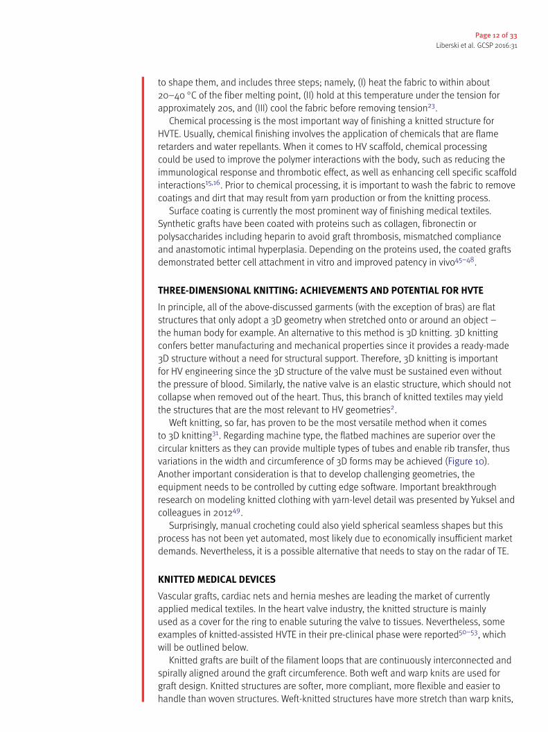
Figure 16. Tube-in-tube valve and its biocompatibility test. Principle of the tube-in-tube valve(A). Still images of closed and open cycles of tube-in-tube valves (B). Histological and fluorescenceimmunohistochemical micrographs of native ovine pulmonary valve (wall), dynamically conditionedtissue-engineered tubular valves (C). Scale bars are 100 µm. The black arrow indicates the textilestructure. Sutured in a silicone tube featuring the sinuses of Valsalva (D). Ultrasound images of thetube-in-tube in closed position (E). Reprinted with permission from51.
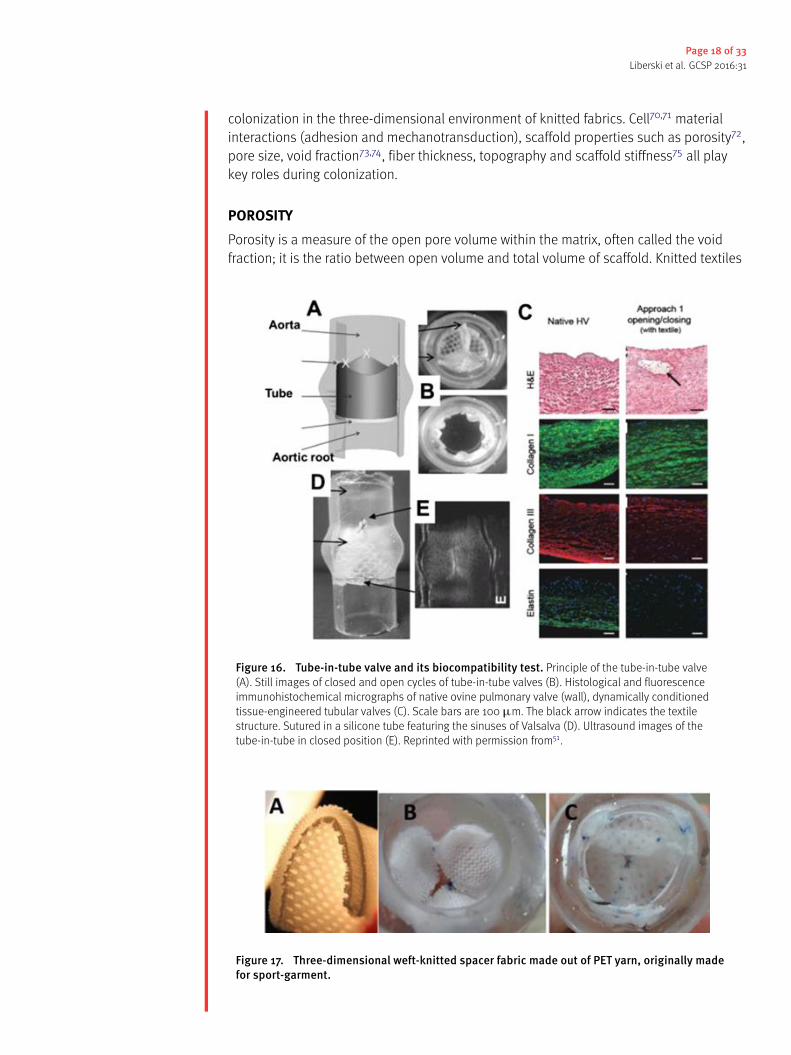
Figure 17. Three-dimensional weft-knitted spacer fabric made out of PET yarn, originally madefor sport-garment.

Page 19 of 33Liberski et al. GCSP 2016:31
are inherently a macroporous structure due to their loop-based nature76. The size ofthe loop can be adjusted, but the minimal size is governed by the size of needle usedfor knitting. Moreover, porosity, types of pores and pore interconnectivity can changedynamically upon exposure of the fabric to mechanical stress. It is acknowledged thatpore size affects cell attachment, migration, depth of cellular in-growth, phenotypicexpression and cell morphology77.
The optimal pore size range depends on the materials as well as cell types78; outsidethis range, cells fail to spread and form networks. For example, endothelial cells (ECs) areable to colonize scaffolds with pore sizes <300 µm79–81. The ‘‘safe pore size range’’ forsupporting cell ingrowth for the majority of mature cells is in the range of 100–150 µm81.Obviously, the porosity of yarns used for knitting is an important factor to considerespecially for multifilament yarns. Filaments packed in yarn will provide the fabric withpores or/and channels oriented lengthwise to the thread. One may hypothesize thatthese channels can be used to drive oriented cellular growth and ECM deposition. Ingeneral, it is reasonable to expect that the knitted structure will leak in contact withblood. To prevent leaking, a coating may be applied on scaffold using ECM30, hydrogels51,nanofiber meshes82 or polymer films. Therefore, the macroporous nature of knittedstructures enhances polymer cell interaction, good contact with blood and enablescellular colonization of the structure.
FILAMENT/FIBER THICKNESSAn important parameter in knitted scaffolds is the microscale thickness of the individualmaterial filaments in the yarn. The filaments in knitted structures are usually highlyorganized with regular repeating pore units (at fabric relaxed state). The filaments’thickness, length, width and shape (circular, rectangular, etc.) will play the role in cellularcolonization of fabrics. It was previously demonstrated that fibers (700nm in diameter)of oriented polycaprolactone nanofibers promoted phenotypic differentiation ofchondrocytes compared with 2D nonporous membranes83. Cells maintain phenotypicshape and guided growth according to nanofiber orientation of oriented fibrousstructures on which they are seeded. Scaffold fibers orientation may enhance the ECMproteins synthesis84. Further studies are necessary to verify if the orientation of filamentsin the yarns may affect cellular colonization in a similar manner22.
FILAMENT TOPOGRAPHYThe surface characteristics of yarns constituting the knitted scaffold can be describedby its topography, comprising of micro- to nano-scale material surface features. Thetopography of the yarn surface may influence the spreading characteristics and activityof cells85. The extrusion-based method of filament production provides the filaments withgrooves, pores and other lengthwise homogenous topographical features. It was shownthat grooves may reshape actin filaments to adjust to the new topography86, or inhibitcell movement and bend the cell cytoskeleton85. Surface roughness can significantlyincrease the cell migration area87 and improve the adhesion and growth of cells88 onpolymer scaffold89. Another way of modifying the yarn surface is by the inclusion ofnanoparticles or by etching the surface of the matrix88,90.
STIFFNESS OF KNITTED STRUCTURESThe resistance of the material to deformation (stiffness) influences cellular activity91,92.Cells show reduced spreading when soluble adhesive ligands are not strongly attached

Page 20 of 33Liberski et al. GCSP 2016:31
to the surface93,94, as scaffolds are unable to withstand cell contractile forces92. Thestiffness of the knitted construct can be increased by heat-setting the fabric23; this needsto be performed carefully since an elevated temperature may permanently melt and joinfilaments of the knitted yarn together and change porosity. Raising23 is another finishingtechnique that may be used for changing the structure and properties of the material,such as enhancing cell /polymer interaction on a given side of the fabric.
MECHANOTRANSDUCTION IN KNITTED STRUCTURESSince knitted structures are more elastic than woven ones, the seeded cells would sensemore stretch and deformation when the knitted fibres are subjected to stretching. Studieshave shown that both mechanical stresses95 and hydrodynamic stresses96 affect cellcolonization. Shear stress initiates multiple signal transduction cascades leading tofunctional changes in endothelial cells23. Endothelial cells grown in a perfusion reactorhave been shown to align in the direction of flow97. Mechanical forces may unfoldselected protein domains, thus providing access to a different set of binding sites ortrigger opening or closing of ion channels98.
Cells experience local shear stress rates when flow through the scaffoldmicroarchitecture occurs. The scaffold architecture controls the transport of nutrientswithin the samples. However, the dynamically changing geometries of knitted structuresmay result in flow irregularities, extracellular matrix washout or local hypoxia98. Thepresence of flow within a reactor also affects the production of ECM components.Therefore, the flow that the scaffold is subjected to in a bioreactor must be closelyregulated to control cell seeding and ECM production.
CELL ADHESION ON THE YARN SURFACEAnother aspect that influences the interaction of the knitted scaffold with the surroundingenvironment is the yarn surface. Cellular adhesion, proliferation and differentiation canbe enhanced by anchoring to the scaffold surface specific cellular binding sites99 orincorporating into the scaffold growth factors100,101.
The knitted structures are often used in a hybrid format with hydrogel; namely,collagens, glycosaminoglycans (GAGs)102,103, alginates or fibrin gel50–53. The hydrogelis used to host the cells and enable their proliferation but it can also be loaded withdrugs or agents responsible for scaffold remodeling. One elegant example of such use ofhydrogel was reported by Baaijens, who loaded hydrogels with fast-releasing monocytechemoattractant protein-1 (MCP-1). MCP-1 released from the gel triggered inflammation-mediated tissue remodeling104.
Another vital method of modifying the properties of yarn surfaces is culturing cellson them. For example, mesenchymal stromal cells (MSC), when seeded on a scaffoldsecreted a cocktail of trophic factors including MCP-1, which initiated a cascade ofimmune responses culminating with tissue remodeling on scaffold105. This strategy hasnot been applied yet for knitted fabrics but there are no obvious obstacles to do so.
The overall efficiency of cellular colonization of knitted fabric is related to structureand degradation rate of polymers used as yarns. For example, biodegradability decreaseswith increase in molecular weight106. A similar decrease of biodegradability is associatedwith denser structure of the crystalline sample, since it would be more impermeable tothe enzymatic attack107.
Importantly, as reviewed elsewhere69, the structural, biological and degradationproperties of the EC matrix also are key factors regulating colonization.

Page 21 of 33Liberski et al. GCSP 2016:31
BASIC METHODS FOR CHARACTERIZING KNITTED SCAFFOLDThe following section will focus on specific requirements for tissue-engineeredconstructs that textile specialists need to understand. This is important becauseobstacles encountered during the scaffold preparation need to be addressed in a mannerthat would not affect the requirements for its final application. For example, for textileengineers the obvious way of providing 3D geometry to the fabric is to seam the material.However, from the perspective of tissue engineers, stitches in the construct may bebeneficial (as a local enforcement), but in other occasions, stitching may need to beavoided, especially if homogeneity of the fabric is desired.
STANDARDIZED METHODS FOR HV SCAFFOLDS CHARACTERIZATIONThe critical parameters of a scaffold and its characteristics are precisely described in theofficial regulations of International Organization for Standardization (ISO). For example,ISO 5840, entitled Cardiovascular implants – Cardiac valve prostheses, consists of threeparts: General requirements108, Surgically implanted heart valve substitutes109 and Heartvalve substitutes implanted by transcatheter techniques110.
According to ISO 5840, the heart valve substitute should meet following basicconditions:
• allow forward blood flow with acceptably small pressure difference,• prevent retrograde flow with acceptably small regurgitation,• be biocompatible,• be resistant to haemolysis,• resists embolization and thrombus formation,• compatible with in vivo diagnostic techniques,• deliverable and implantable in the target population,• remain fixed once placed, have acceptable noise level,• have reproducible function, maintain its functionality for a reasonable lifetime,• consistent with its generic class and also maintain its functionality and sterility for areasonable shelf life prior to implantation.
These regulations concern all the components of the heart valve substitute.
FLUID MECHANICAL PERFORMANCEHydrodynamic testing is used to ascertain information on the fluid mechanical propertieswithin the valve. The testing provides indicators of valve performance in terms of load tothe heart, and potential for blood stasis and damage, which is important from the pointof view of risk assessment. The tests should include steady flow testing, pulsatile flowtesting, and steady leakage flow testing. Where applicable, testing should be performedusing a test fluid of isotonic saline, blood or a blood-equivalent fluid whose physicalproperties (e.g. specific gravity, viscosity at working temperatures) are appropriate to thetest being performed. The risk assessment shall play a role in the choice of the test fluid.
VALVE LIFETIME ESTIMATIONThe durability assessment allows an estimation of the proper function of the scaffoldover its lifetime. The testing should prove that the heart valve substitute (in case of aflexible one) will remain functional for 200 million cycles. During the durability testing,the defined target peak differential pressure across the closed valve shall be maintained
Page 22 of 33Liberski et al. GCSP 2016:31
for 95% or more of all the test cycles. The testing should also be conducted under in vivoconditions for fatigue performance of the heart valve substitute and all its components todetermine the structural life time of the material.
PRECLINICAL TESTS FOR HEART VALVESPreclinical evaluation in vivo should be focused on heamodynamic performance ofthe heart valve assessed via in vitro testing, surgical handling of the scaffold and itsaccessories, and various biological reactions of the material with the tissue, mainly:
• healing characteristics (pannus formation, tissue overgrowth)• haemolysis• thrombus formation• embolization• foreign body reaction (inflammation, rejection)• calcification (flexible valves)• acoustic characteristics (rigid valves), if manufacturer claims are made on this issue• structural deterioration and/or non-structural dysfunction• cavitation
BIOCOMPATIBILITY OF MATERIALS AND COMPONENTS IN THE HEART VALVEBiocompatibility of materials and components used in heart valve substitutes shouldbe determined in accordance to guidelines described in ISO 10993-1. During the hazardidentification stage of a biological safety evaluation, the information obtained shouldbe sufficient to allow identification of potential toxicological hazards and the potentialfor effects on relevant haematological characteristics. For heart valve substitutes usinganimal tissue or their derivatives, the risk associated with the use of these materialsshould be evaluated in accordance with EN 12442-1/2/3:2008.
OTHER PROPERTIES OF MATERIALS AND COMPONENTS IN THE HEART VALVEFrom the point of view of material performance and risk assessment, it is crucial to knowthe basic properties of materials after processing and modifications. The evaluationshould include bulk, surface, chemical, and mechanical properties of material. Allmeasurements should be performed on materials or components as they would be foundin the finished product. This includes all subsequent treatments after the fabrication.
The evaluation of textile scaffold bulk properties includes: identification of materials inscope of the chemical composition and purity, density, porosity as well as permeability,microstructure e.g. defects formation, glass transition temperature, melt index, meltingpoint, hydraulic expansion and biostability in physiological fluids.
For the modified scaffold, important assessment methods should include:
• surface chemical composition• surface topology/roughness• surface charge and charge density• critical surface tension
All the measurements should be performed after all treatments e.g. sterilization, asthese may physically affect the surface properties of the material.
Mechanical and chemical engineering properties allow the evaluation of theperformance of the heart valve scaffold in the intended site and also providesinformation on the possible risks resulting from scaffold processing and materials used.

Page 23 of 33Liberski et al. GCSP 2016:31
These properties include: wear resistance, friction coefficient, peel strength, flexural andcompressive strength, tensile strength, tensile strain to failure, strain energy to failure,residual stress, stress relaxation, fracture toughness, crack growth velocity, fatigue life,potential stress corrosion, tear strength, Young’s modulus, Poisson ratio, dynamic moduliincluding storage and loss moduli.
Nevertheless, in the early stages of scientific development and proof of conceptcommunications, the spectrum of analysis should be narrower, as its aims are to enablescientific discussion, open ideas for critique and make subsequent improvements.
Tissue engineering cannot be dissociated from relevant clinical standards and relatedsafety issues. Therefore, it is especially important to develop a good understanding ofthe limitations that need to be addressed111. To illustrate this with an example, whenit comes to knitting the HV scaffold with bioresorbable PCL yarns, the following issueshould be noted. PCL has a low melting temperature, therefore devices made fromit cannot be autoclaved. Also, sterilization via high-energy irradiation may rearrangethe chemical bonds in PCL. This will affect biocompatibility and degradation rates112.Moreover, immediately after implementation, PCL starts to degrade. It is reasonable toexpect quicker degradation in places subjected to higher dynamic mechanical stress.Perhaps at these locations, the scaffold will need to be enforced by less fragile polymers.Regions of the scaffold unoccupied by cells may degrade and yield short fibrils that willcirculate in blood. It is not clear if, in that form, the PCL would degrade quickly enough toavoid a build up of plaques inside the veins.
BASIC MECHANICAL TESTS OF HV SCAFFOLDSThere are several methods to mechanically characterize scaffolds for HVTE. Usually,the first tests involve tensile testing. Tensile testing is mainly performed in a uniaxialmachine, but it could also be done biaxially. This test gives a measure of the sample’selastic modulus (stiffness, E), ultimate tensile strength (UTS), strain-to-failure ("f),yield stress and yield strain. Several studies113–115 determined average values for theseproperties in native valves, which are displayed in Table 2, where circ is thecircumferential direction and rad is the radial. It is important to remember that theleaflets contain collagen fibers that are not initially straight. As the tensile testprogresses, the fibers will be stretched until they are straight, which will require higherstresses. This will translate to an initial region in the curve where the modulus is low,which will develop to an elastic region with higher modulus, when the collagen fibersare straight. The values of moduli displayed in Table 2 correspond to the region wherethe fibers are already straightened.
Studies on knitted scaffolds have to be able to achieve similar values to the nativevalve in tensile testing. Table 2 shows a great range in the values of elastic modulusfor heart valves. This could be explained due to species variability, however even whencomparing studies in porcine valves, the highest value for circumferential elastic modulusis 20x higher than the lower value116,117.
Lee et al. used strips of 5 mm (circumferential) and 8 mm (radial), explaining thatstrips with less than 4 mm and 6 mm in width, respectively, did not produce a stableresponse after preconditioning with cyclic loading and eventually failed, therefore theycould not be representative of the in vivo structure117. This should be taken into accountwhen undertaking mechanical tests, since the preconditioning must be appropriate.Sauren et al. found that it is necessary not to exceed the first elongation in subsequentcycles to achieve the required preconditioning118. It was also found that aortic valves arepreconditioned after a maximum series of ten cycles.

Page24
of33Liberskietal.GCSP
2016:31
Table 2 Typical values obtained from tensile testing for native valves.
Sample Ecirc (MPa) Erad (MPa) Ecirc/Erad UTS circ (MPa) UTS rad (MPa) "f circ (%) "f rad (%)
Sheep AV114 3.84 ⇠0.2 ⇠19,2 ⇠2 ⇠1.5 ⇠20 ⇠50Fresh porcine AV leaflets117 54.6 ± 7.4 7.82 ± 0.58 ⇠7 6.25 ± 0.9 1.18 ± 0.09 30.8 ± 3.2 62.0 ± 3.5Porcine AV leaflets118 28 ± 10 1.33 ± 0.42 ⇠21Porcine AV116 3.35 1.09 3.2Human AV116 3.52 2.27 ⇠1.6Porcine ventricularis 7.41 ⇥ 10�3 3.68 ⇥ 10�3 ⇠2Porcine fibrosa119 13.02 ⇥ 10�3 4.65 ⇥ 10�3 ⇠2.8

Page 25 of 33Liberski et al. GCSP 2016:31
Table 3 Values for burst strength of different scaffolds.
Material Burst strength (mmHg)
Fibrin without textile reinforcement51 44.0 ± 18.5Fibrin with textile reinforcement51 90.7 ± 14.0TexMi valves51 554.7 ± 92.2Native ovine mitral valve51 5272.3 ± 538.0Tube-in-stent PET textile with fibrin53 146.1 ± 46.0Tube-in-stent PET textile with fibrin after cultivation53 321.1 ± 30.9Tube-in-stent PET textile with fibrin after cultivation and crimping53 334.7 ± 34.3
Another important mechanical test, especially for knitted scaffolds, is burst strength.This test exposes the sample to increasing pressures until structural failure occurs, amoment characterized by a loss in pressure. Table 3 displays several values for the burststrength of the scaffolds.
TexMi is a mitral valve scaffold made with fibrin in a knitted PET structure53. Theknitted structure doubles the strength of the fibrin scaffold to 90 mmHg. This increaseis greatly enhanced by the TexMi design to a value of ⇠555 mmHg. However, this valueis still significantly lower (only 10%) than the one obtained for ovine mitral valves. In thetube-in-stent fibrin-based PET knitted scaffold made by Moreira et al.53, a burst pressureof 146.1 ± 46.0 mmHg was measured. After the cultivation with endothelial cells for 21days, the valves were crimped from 22 mm to 8 mm and kept in the crimped state for20 min before returning to the original size. The test was performed again and the burstpressure before crimping was increased to 321.1 ± 30.9 mmHg.
After crimping, the value did not significantly change. This is an importantconsideration, because during the implantation of the valve, crimping will occur, and thishas been shown to damage the collagen and endothelial layer120. The similar results forburst strength before and after crimping obtained by Moreira et al.53 can be explained bythe reduced time in the crimped condition. Therefore, when designing a knitted scaffold,the effect and duration of crimping must be taken into consideration to see if the damageto the endothelial layer will significantly decrease the mechanical properties.
Finally, the mean pressure gradient and regurgitation of the knitted scaffolds mustalso be evaluated. The measurements of the pressure must be performed upstream anddownstream of the valve at aortic conditions: 80-120 mmHg aortic pressure (100 mmHgmean), 70 bpm frequency, 5L/min cardiac output in a pulsatile flow53. Commerciallyavailable transcatheter aortic valve implantation (TAVI) systems have a mean gradient of9.3 ± 4.5 mmHg121. A similar value was obtained with the tube-in-stent knitted PET withfibrin53 that had a mean pressure gradient of 7.3 ± 1.5 mmHg before and 6.8 ± 1.7 mmHgafter crimping, values that were statistically not significantly different. The regurgitationwas 15.1 ± 2.5 % before and 15.3 ± 3.6% after crimping, below the 20% limit defined byISO 5840:2012 for a 23 mm valve replacement. In the knitted fibrin-covered PCL scaffolddescribed by Lieshout50, the regurgitation was 39 ± 3%, due to fibrin-related leakage.This value is unacceptable, therefore the method and materials used to create thisscaffold need to be revisited.
BASIC BIOLOGICAL TESTS OF HV SCAFFOLDSIn addition to assessing mechanical properties, the ability of the scaffold to attract andgrow cells that will produce the ECM matrix must also be studied. This includes, after

Page 26 of 33Liberski et al. GCSP 2016:31
culture with the desired cells, histology studies, immunohistochemistry, ECM contentassays, and microscopy techniques such as scanning electron microscopy (SEM).
Endothelial cells, smooth muscle cells (SMC) and fibroblasts are some of the cellsused for culture of scaffold for HV. The source of the cells to be isolated is an importantfactor. It has been shown that tissue engineered vascular constructs made with arterialcells developed a significant synthesis of elastin that did not occur in the constructsmade with venous cells122. Elastin plays an important role in the elastic deformation ofvalves, and in HVTE elastin is hardly formed in vitro123. However, the TexMi scaffold51showed a significant synthesis of elastin in the stress lines with cells from ovine umbilicalveins, while cells from ovine umbilical arteries did not produce elastin. Therefore, the cellsource is a meaningful variable in culture of scaffolds for HVTE. Cell culture ideally shouldbe performed in dynamic cultivation, in a bioreactor for conditioning and to obtain theproper phenotype. After 21 days, ECM production is expected to occur. The protocolvaries, for example, TexMi51 uses 5 days in static cultivation, 6 days at 30 bpm, 6 daysat 40 bpm and 2 days at 60 bpm, while tube-in-stent53 uses 7 days in static cultivation,then 14 days in dynamic conditions that varied from 20–35 bpm.
For the histology, the scaffold should be fixed, embedded and sectioned after culture.Morphology of the tissue can be analyzed by using Hematoxylin and Eosin (H&E) stain,and tissue development can be analyzed by Gomori’s Trichrome stain. H&E shouldshow a homogeneous distribution of cells across the scaffold’s thickness and Gomori’sTrichrome, in the context of HVTE, should show the presence of collagen fibers.
In immunohistochemistry, the tissue should be incubated with antibodies that stainagainst ↵-smooth muscle actin (↵-SMA), collagen I, collagen III, elastin, GAGs, CD31(endothelial cell marker) and fibrinogen. Culture on TexMi51 produced type I and IIIcollagen longitudinally across the thickness of the scaffold. In the native valve, collagenis the main ECM protein. Collagen content can be assessed by a hydroxyproline assay124.SEM should be used to analyze if a homogeneous layer of cells was obtained. In the caseof crimping53, SEM will be particularly useful to determine the amount of damage to theendothelial layer.
BASIC TESTS OF THE KNITTED FABRICSFrom the perspective of knitted textile characterization, the list of pivotal parametersand measurements includes; thickness, surface mass, burst strength and identificationof fibers in textiles.
Thickness should be evaluated according to ISO 5084-1999 Textiles - Determinationof Thickness of Textiles and Textile Products and surface mass should be evaluatedaccording to PN-EN 12127:2000. Reduction in the above-mentioned parameters improvesthe long-term biocompatibility of scaffolds125. Those parameters are crucial as theyinfluence material elasticity. Scaffolds need to be elastic and conformable, on the otherhand should not be too flexible as this could cause the knitted fabric to curl.
To alter the properties of fibres, many producers use chemical modifiers during thefibre forming process. Hence characterization and analysis of the chemical constitutionof a fibre are essential to secure safe usage of scaffolds. It is important to determineall types of fibers present in a sample of textile material of unknown composition. Thestandard outlining analytic methods used to determine chemical composition of textilematerial is ASTM D276 ‘‘Standard Test Methods for Identification of Fibers in Textiles’’.This standard only allows identification of the generic types of fibers present in a sampleof textile material of unknown composition.

Page 27 of 33Liberski et al. GCSP 2016:31
Since knitted woven fabrics contain oil, lubricants and delustrants, an integral part ofthe production process, but unacceptable in medical products, the appropriate surfacecleaning method should be applied. Van Lieshout et al.50 proposed a simple method ofremoving contaminants from yarn. To dispose of the antistatic build-up layer of oils, thescaffold sample was washed in soap water for 24 hours, flushed with water extensively,and shaken in 70% alcohol overnight to obtain a sterile aortic valvular scaffold.
Due to the fact that 3 to 5 litres of blood is pumped through the valve during thecardiac cycle in each minute126, the scaffold should have sufficient mechanical propertiesto work in such conditions. Burst strength testing is a common method to characterizethe mechanical behavior of scaffolds by determining the pressure at which structuralfailure occurs. It should be assessed according to ISO 13938-2:2002 ‘‘Textiles - Burstingproperties of fabrics - Part 2: Pneumatic method for determination of bursting strengthand bursting distension’’ Standard. It should be noted that this test must be performedin two states, dry and wet (in physiological fluids). The strength can be different in bothstates. Additionally tensile properties of knitted fabrics shall be evaluated accordingto ISO 13934-1:2013 ‘‘Textiles - Tensile properties of fabrics - Part 1: Determination ofmaximum force and elongation at maximum force using the strip method’’. The methodspecifies the determination of the maximum force and elongation at maximum forceof test specimens in equilibrium with the standard atmosphere for testing and of testspecimens in the wet state. Moreover the knitted scaffold should open and closeproperly. In127 authors showed that the knitted scaffold is stronger than the spun scaffoldwhich remained intact under physiological loading, whereas the spun scaffold is not.
Because scaffolds will have to be in contact with blood and human fluid, the scaffoldshould have pH similar to pH of blood (ISO 3071:2007 ‘‘Textiles - Determination of pH ofaqueous extract’’).
CONCLUSIONS AND FUTURE DIRECTIONSKnitted structures appear to be a suitable candidate for HVTE application owing to theirinherent design and structural flexibility. In addition, it is possible to design anisotropicelasticity in knitted structures, which could eventually be tailored to match the onepresent in the native valve. Some of the latest developments in knitted meshes usebiological coatings to improve the tissue growth. This also can help to model thestructure to match the anatomy of the implant site30. To make the concept of intelligentscaffold a reality, much more work needs to be done on enhancing yarn-cell specificinteractions. This involves two distinct directions that will be explored in the future:modifications of the final construct and modification of yarns prior to knitting. Somepromising examples of cell specific polymer surface modifications have already beenreported and include enhancing the polymers with antibodies, peptides, aptamers andenzymes. The textile-based smart scaffold requires a combined input from the advancedbiomechanics and textile design together in order to realize the full clinical potential oftextile HV prosthesis.
The general drawback of knitting is that it inherently provides a highly porousstructure that can leak upon exposure to fluids. This can be, to some extent, overcomeby applying hydrogels (fibrin, HA, alginate or others62) as a sealant. A very attractiveway of sealing the knitted structure is combining it with woven or non-woven fabrics.The example in Figure 18A–18D, shows a knitted leaflet on which the anisotropic sheetof PCL nanofibres was glued. A further important potential of knitted structures is thatthe loops architecture can guide the growth of cells and ECM secreted by the cells

Page 28 of 33Liberski et al. GCSP 2016:31
Figure 18. Weft knitted PCL yarns (A). Leaflet shaped using PCL fabric and PCL anisotropicnanofibril nonwoven sheets (B1), view from aortic side (B2). SEM of composite of knitted PCL microfibersand non woven sheet of PCL nanofibers (D). Knitted fabric shaped in leaflets cast in PDMS mold, sideview (C1) and aortic side view (C2). The interior of mold is shaped in valve geometry. Performance of valvewas roughly illustrated in water bath, see video at128. Adipose derived stem cells growing on knitted loopsof PCL yarns (E), Bright Field image (E1), and visualization of cells’ nuclei, after staining with DAPI, imagetaken with DAPI filter (E2). Scale bars are 1 mm.
(Figure 18E). More research is needed to confirm if, after yarn degradation, the structurewill preserve the ‘‘imprinted’’ elastic properties. In fact, this is important not only for HVTEbut for cardiac regeneration in general. In myocardial infarction, damaged myocardiumis replaced by scar tissue that is less elastic than normal myocardium. Although the scartissue consists of viable cells capable of producing isotropic fibril ECM proteins, it is verystiff. A bioactive knitted structure is then an appealing option that may yield an elasticliving construct made out of aligned ECM proteins from the cells that have colonized thatyarn. To summarize, the future is bright and even the sky is not a limit (knitted yarns arealso used as an element of composites use in astronauts’ space suits).
This paper also reviewed the design aspect of knitted textiles intended for HVTE. Thethree dimensional structure of leaflets and their unique mechanical properties (non-linearity, anisotropy, compliance) have been widely researched and reported1,2. However,these features remain widely neglected while designing the scaffolds for HV replacement.Currently available HV substitutes cannot remodel and be replaced by endogenouslyrecruited cells129. Moreover, their structural geometry is often not analogous to native HV.This difference can later lead to clinical complications arising from behavioural mismatchat the implant anastomosis. These observations ultimately raise the importance ofunderstanding the structure and biomechanics of an HV before adapting a textilestructure from its conventional application area to a biological environment consistingof complex structure and functions such as the aortic valve. A smart valve scaffold

Page 29 of 33Liberski et al. GCSP 2016:31
with structural characteristics that closely resemble a native valve will present lesscomplications which, in turn, translates to a longer-lasting durable implant.
REFERENCES[1] Arjunon S, Rathan S, Jo H, Yoganathan AP. Aortic valve: mechanical environment and mechanobiology.
Ann Biomed Eng. 2013;41(7):1331–46.[2] Chester AH, El-Hamamsy I, Butcher JT, Latif N, Bertazzo S, Yacoub MH. The living aortic valve: From
molecules to function. Glob Cardiol Sci Pract . 2014;2014(1):52–77.[3] Yacoub MH, Kilner PJ, Birks EJ, Misfeld M. The aortic outflow and root: a tale of dynamism and crosstalk.
Ann Thorac Surg. 1999;68(3 Suppl):S37–43.[4] Hasan A, Ragaert K, Swieszkowski W, Selimovi¢ S, Paul A, Camci-Unal G, et al. Biomechanical properties
of native and tissue engineered heart valve constructs. J Biomech. 2014;47(9):1949–63.[5] Yacoub MH. In Search of Living Valve Substitutes*. J Am Coll Cardiol. 2015;66(8):889–91.[6] Zafar F, Hinton RB, Moore RA, Baker RS, Bryant R, Narmoneva DA, et al. Physiological Growth,
Remodeling Potential, and Preserved Function of a Novel Bioprosthetic Tricuspid Valve: TubularBioprosthesis Made of Small Intestinal Submucosa-Derived Extracellular Matrix. J Am Coll Cardiol.2015;66(8):877–88.
[7] Khan AA, Vishwakarma SK, Bardia A, Venkateshwarulu J. Repopulation of decellularized whole organscaffold using stem cells: an emerging technology for the development of neo-organ. J Artif Organs.2014;17(4):291–300.
[8] Hodde J. Naturally occurring scaffolds for soft tissue repair and regeneration. Tissue Eng.2002;8(2):295–308.
[9] Sun J, Tan H. Alginate-Based Biomaterials for Regenerative Medicine Applications.Materials.2013;6(4):1285–309.
[10] El-Sherbiny IM, Yacoub MH. Hydrogel scaffolds for tissue engineering: Progress and challenges. GlobCardiol Sci Pract . 2013;2013(3):316–42.
[11] Freed LE, Vunjak-Novakovic G, Biron RJ, Eagles DB, Lesnoy DC, Barlow SK, et al. Biodegradable PolymerScaffolds for Tissue Engineering. Nat Biotechnol. 1994;12(7):689–93.
[12] Koo M-A, Kang JK, Lee MH, Seo HJ, Kwon B-J, You KE, et al. Stimulated migration and penetrationof vascular endothelial cells into poly (L-lactic acid) scaffolds under flow conditions. Biomater Res.2014;18:7.
[13] Chew SA, Arriaga M, Hinojosa V. Effects of surface area to volume ratio of plga scaffolds with differentarchitectures on scaffold degradation characteristics and drug release kinetics. J Biomed Mater Res A.2016.
[14] Jafari M, Paknejad Z, Rad MR, Motamedian SR, Eghbal MJ, Nadjmi N, et al. Polymeric scaffolds in tissueengineering: a literature review. J Biomed Mater Res B Appl Biomater . 2015;n/a–n/a.
[15] Kang C-K, Lim W-H, Kyeong S, Choe W-S, Kim H-S, Jun B-H, et al. Fabrication of biofunctional stents withendothelial progenitor cell specificity for vascular re-endothelialization. Colloids Surf B Biointerfaces.2013;102:744–51.
[16] Lim W-H, Seo W-W, Choe W, Kang C-K, Park J, Cho H-J, et al. Stent coated with antibody against vascularendothelial-cadherin captures endothelial progenitor cells, accelerates re-endothelialization, andreduces neointimal formation. Arterioscler Thromb Vasc Biol. 2011;31(12):2798–805.
[17] Li Q, Wang Z, Zhang S, Zheng W, Zhao Q, Zhang J, et al. Functionalization of the surface of electrospunpoly(epsilon-caprolactone) mats using zwitterionic poly(carboxybetaine methacrylate) and cell-specificpeptide for endothelial progenitor cells capture.Mater Sci Eng C . 2013;33(3):1646–53.
[18] Ji Q, Zhang S, Zhang J, Wang Z, Wang J, Cui Y, et al. Dual functionalization of poly("-caprolactone) filmsurface through supramolecular assembly with the aim of promoting in situ endothelial progenitor cellattachment on vascular grafts. Biomacromolecules. 2013;14(11):4099–107.
[19] Esposito CL, Cerchia L, Catuogno S, De Vita G, Dassie JP, Santamaria G, et al. Multifunctional Aptamer-miRNA Conjugates for Targeted Cancer Therapy.Mol Ther . 2014;22(6):1151–63.
[20] Kalsi K, Lawson C, Dominguez M, Taylor P, Yacoub MH, Smolenski RT. Regulation of ecto-5’-nucleotidaseby TNF-alpha in human endothelial cells.Mol Cell Biochem. 2002;232(1-2):113–9.
[21] Sohier J, Carubelli I, Sarathchandra P, Latif N, Chester AH, Yacoub MH. The potential of anisotropicmatrices as substrate for heart valve engineering. Biomaterials. 2014;35(6):1833–44.
[22] Hwang CM, Park Y, Park JY, Lee K, Sun K, Khademhosseini A, et al. Controlled cellular orientation onPLGA microfibers with defined diameters. Biomed Microdevices. 2009;11(4):739–46.
[23] Horrocks AR, Anand SC, Anand S. Handbook of Technical Textiles. Taylor & Francis; 2000. 584 p.[24] vasant [Internet]. [cited 2015 Sep 27]. Available from: http://www.vasantkothari.com/.[25] Kommunikation K+ FGM und. STOLL - Flachstrickmaschinen, CMS Flachstrickmaschinen, CMS, Flat
knitting machines, CMS Flat knitting machines - Reutlingen, Deutschland [Internet]. [cited 2015 Sep 27].Available from: http://www.stoll.com/stoll-produkte.
[26] Large Diameter | Santoni [Internet]. [cited 2015 Sep 27]. Available from: http://www.santoni.cn/en/large-diameter.
[27] Research Journal of Textile and Apparel [Internet]. [cited 2015 Sep 27].Available from: http://www.rjta.org/pa_inside.php?issue_id=01_1.

Page 30 of 33Liberski et al. GCSP 2016:31
[28] Kopias K. Budowa i technologia dzianin kolumienkowych.Wydawnictwo Politechniki äódzkiej .2010;188 p.
[29] Kopias K. Budowa i technologia dzianin rz°dkowych: praca zbiorowa.Wydawnictwo Politechnikiäódzkiej . 2013;169 p.
[30] Singh C, Wong CS, Wang X. Medical Textiles as Vascular Implants and Their Success to Mimic NaturalArteries. J Funct Biomater . 2015;6(3):500–25.
[31] Underwood J, Underwood J. The design of 3D shape knitted preforms. 2009 [cited 2015 Sep 27];Available from: https://researchbank.rmit.edu.au/view/rmit:6130.
[32] Jun Y, Kang E, Chae S, Lee S-H. Microfluidic spinning of micro- and nano-scale fibers for tissueengineering. Lab Chip. 2014;14(13):2145–60.
[33] Tamayol A, Akbari M, Annabi N, Paul A, Khademhosseini A, Juncker D. Fiber-Based Tissue Engineering:Progress, Challenges, and Opportunities. Biotechnol Adv . 2013;31(5):669–87.
[34] Knit Together | Jacquard Knitting Patterns [Internet]. [cited 2015 Sep 27]. Available from: http://knit-together.com/pattern/knitting-stitch-patterns/jacquard-patterns.
[35] IMPROVED WARP KNITTING MACHINE FOR SYMMETRIC MULTI-PLIES [Internet]. [cited 2016 Feb 3].Available from: http://www.iccm-central.org/Proceedings/ICCM16proceedings/contents/pdf/FriB/FrBA2-04ge_franzkeg221527p.pdf.
[36] Potluri P, Sharma S, Ramgulam R. Comprehensive drape modelling for moulding 3D textile preforms.Compos Part Appl Sci Manuf . 2001;32(10):1415–24.
[37] Nike Flyknit [Internet]. [cited 2015 Sep 27]. Available from: http://www.nike.com/us/en_us/c/innovation/flyknit.
[38] Sjoblom L. French Seam Studio: 3D Knitting, The First Exploration In 3D [Internet]. [cited 2015 Sep 27].Available from: http://frenchseamstudio.blogspot.qa/2013/11/3d-knitting-first-exploration-in-3d.html.
[39] MaxiFlex R� UltimateTM [Internet]. ATG R�Glove Solutions. [cited 2015 Sep 27]. Available from: http://www.atg-glovesolutions.com/en/maxiflex-3/maxiflex-ultimate%E2%84%A2-8/34-874-34/.
[40] Bras Don’t Cause Breast Cancer, According to New Study [Internet]. [cited 2015 Sep 27]. Available from:http://jezebel.com/bras-dont-cause-breast-cancer-according-to-new-study-1630996574.
[41] Hosiery -images [Internet]. [cited 2015 Sep 27]. Available from http://www.cifra-spa.net/en/products/hosiery.
[42] CEP Compression - The Intelligent Sportswear [Internet]. [cited 2015 Sep 27]. Available from:http://www.cepcompression.com/.
[43] 2000.jpg (Obrazek JPEG, 780⇥320 pikseli) [Internet]. [cited 2015 Sep 27]. Available from:http://explore.speedousa.com/img/heritage/2000.jpg.
[44] Dean B, Bhushan B. Shark-skin surfaces for fluid-drag reduction in turbulent flow: a review. Philos TransR Soc Lond Math Phys Eng Sci . 2010;368(1929):4775–806.
[45] Burkel WE, Vinter DW, Ford JW, Kahn RH, Graham LM, Stanley JC. Sequential studies of healingin endothelial seeded vascular prostheses: histologic and ultrastructure characteristics of graftincorporation. J Surg Res. 1981;30(4):305–24.
[46] Fujita Y, Wu MH, Ishida A, Shi Q, Walker M, Hammond WP, et al. Accelerated healing of Dacron graftsseeded by preclotting with autologous bone marrow blood. Ann Vasc Surg. 1999;13(4):402–12.
[47] Pasquinelli G, Freyrie A, Preda P, Curti T, D’Addato M, Laschi R. Healing of prosthetic arterial grafts.Scanning Microsc . 1990;4(2):351–62.
[48] Tolan M, Wells F, Kendall S, Large S, Wallwork J. Clinical experience with a collagen impregnated wovenDacron graft. J Cardiovasc Surg (Torino). 1995;36(4):323–7.
[49] Yuksel C, Kaldor JM, James DL, Marschner S. Stitch Meshes for Modeling Knitted Clothing with Yarn-levelDetail. ACM Trans Graph. 2012;31(4):37:1–37:12.
[50] Van Lieshout M, Peters G, Rutten M, Baaijens F. A knitted, fibrin-covered polycaprolactone scaffold fortissue engineering of the aortic valve. Tissue Eng. 2006;12(3):481–7.
[51] Moreira R, Gesche VN, Hurtado-Aguilar LG, Schmitz-Rode T, Frese J, Jockenhoevel S, et al. TexMi:development of tissue-engineered textile-reinforced mitral valve prosthesis. Tissue Eng Part C Methods.2014;20(9):741–8.
[52] Weber M, Heta E, Moreira R, Gesche VN, Schermer T, Frese J, et al. Tissue-engineered fibrin-based heartvalve with a tubular leaflet design. Tissue Eng Part C Methods. 2014;20(4):265–75.
[53] Moreira R, Velz T, Alves N, Gesche VN, Malischewski A, Schmitz-Rode T, et al. Tissue-engineered heartvalve with a tubular leaflet design for minimally invasive transcatheter implantation. Tissue Eng Part CMethods. 2015;21(6):530–40.
[54] Singh C, Wang X. A new design concept for knitted external vein-graft support mesh. J Mech BehavBiomed Mater . 2015;48:125–33.
[55] Richardt D, Karluss A, Schmidtke C, Sievers H-H, Scharfschwerdt M. A new sinus prosthesis for aorticvalve-sparing surgery maintaining the shape of the root at systemic pressure. Ann Thorac Surg.2010;89(3):943–6.
[56] Hasegawa M, Azuma T. Mechanical properties of synthetic arterial grafts. J Biomech. 1979;12(7):509–17.[57] Chitsaz S, Wenk JF, Ge L, Wisneski A, Mookhoek A, Ratcliffe MB, et al. Material properties of CorCap
passive cardiac support device. Ann Thorac Surg. 2013;95(1):148–54.[58] B. Braun. Indonesia - Products - Optilene R�Mesh Elastic [Internet]. [cited 2015 Sep 27]. Available from:
http://www.bbraun.co.id/cps/rde/xchg/cw-bbraun-id-id/hs.xsl/products.html?prid=PRID00001223.

Page 31 of 33Liberski et al. GCSP 2016:31
[59] Treasure T, Takkenberg JJM, Golesworthy T, Rega F, Petrou M, Rosendahl U, et al. Personalised externalaortic root support (PEARS) in Marfan syndrome: analysis of 1-9 year outcomes by intention-to-treat in a cohort of the first 30 consecutive patients to receive a novel tissue and valve-conservingprocedure, compared with the published results of aortic root replacement. Heart Br Card Soc .2014;100(12):969–75.
[60] Verbrugghe P, Verbeken E, Pepper J, Treasure T, Meyns B, Meuris B, et al. External aortic root support: ahistological and mechanical study in sheep. Interact Cardiovasc Thorac Surg. 2013;17(2):334–9.
[61] Pepper J, Goddard M, Mohiaddin R, Treasure T. Histology of a Marfan aorta 4.5 years after personalizedexternal aortic root support. Eur J Cardio-Thorac Surg off J Eur Assoc Cardio-Thorac Surg.2015;48(3):502–5.
[62] El-Sherbiny IM, Yacoub MH. Hydrogel scaffolds for tissue engineering: Progress and challenges. GlobCardiol Sci Pract . 2013;2013(3):316–42.
[63] Loerakker S, Argento G, Oomens CWJ, Baaijens FPT. Effects of valve geometry and tissueanisotropy on the radial stretch and coaptation area of tissue-engineered heart valves. J Biomech.2013;46(11):1792–800.
[64] Driessen NJ, Boerboom RA, Huyghe JM, Bouten CV, Baaijens FP. Computational analyses of mechanicallyinduced collagen fiber remodeling in the aortic heart valve. J Biomech Eng. 2003;125(4):549–57.
[65] Ballotta V, Driessen-Mol A, Bouten CVC, Baaijens FPT. Strain-dependent modulation of macrophagepolarization within scaffolds. Biomaterials. 2014;35(18):4919–28.
[66] van Loon SLM, Smits AIPM, Driessen-Mol A, Bouten FPTB, CVC. The Immune Response in InSitu Tissue Engineering of Aortic Heart Valves. 2013 Jun 12 [cited 2015 Sep 27]; Available from:http://www.intechopen.com/books/calcific-aortic-valve-disease/the-immune-response-in-in-situ-tissue-engineering-of-aortic-heart-valves.
[67] Syedain ZH, Lahti MT, Johnson SL, Robinson PS, Ruth GR, Bianco RW, et al. Implantation of a Tissue-engineered Heart Valve from Human Fibroblasts Exhibiting Short Term Function in the Sheep PulmonaryArtery. Cardiovasc Eng Technol. 2011;2(2):101–12.
[68] Flanagan TC, Sachweh JS, Frese J, Schnöring H, Gronloh N, Koch S, et al. In vivo remodeling andstructural characterization of fibrin-based tissue-engineered heart valves in the adult sheep model.Tissue Eng Part A. 2009;15(10):2965–76.
[69] Lawrence BJ, Madihally SV. Cell colonization in degradable 3D porous matrices. Cell Adhes Migr .2008;2(1):9–16.
[70] Tissue engineering. Nat Biotechnol. 2000;18:IT56–8.[71] Langer R, Vacanti JP. Tissue engineering. Science. 1993;260(5110):920–6.[72] Dar A, Shachar M, Leor J, Cohen S. Optimization of cardiac cell seeding and distribution in 3D porous
alginate scaffolds. Biotechnol Bioeng. 2002;80(3):305–12.[73] Zeltinger J, Sherwood JK, Graham DA, Müeller R, Griffith LG. Effect of pore size and void fraction on
cellular adhesion, proliferation, and matrix deposition. Tissue Eng. 2001;7(5):557–72.[74] Ranucci CS, Moghe PV. Substrate microtopography can enhance cell adhesive and migratory
responsiveness to matrix ligand density. J Biomed Mater Res. 2001;54(2):149–61.[75] Balgude AP, Yu X, Szymanski A, Bellamkonda RV. Agarose gel stiffness determines rate of DRG neurite
extension in 3D cultures. Biomaterials. 2001;22(10):1077–84.[76] Treasure T, Takkenberg JJM, Golesworthy T, Rega F, Petrou M, Rosendahl U, et al. Personalised external
aortic root support (PEARS) in Marfan syndrome: analysis of 1–9 year outcomes by intention-to-treat ina cohort of the first 30 consecutive patients to receive a novel tissue and valve-conserving procedure,compared with the published results of aortic root replacement. Heart . 2014;100(12):969–75.
[77] O’Brien FJ, Harley BA, Yannas IV, Gibson LJ. The effect of pore size on cell adhesion in collagen-GAGscaffolds. Biomaterials. 2005;26(4):433–41.
[78] Teebken OE, Haverich A. Tissue engineering of small diameter vascular grafts. Eur J Vasc Endovasc SurgOff J Eur Soc Vasc Surg. 2002;23(6):475–85.
[79] Wang YC, Ho C-C. Micropatterning of proteins and mammalian cells on biomaterials. FASEB J Off PublFed Am Soc Exp Biol. 2004;18(3):525–7.
[80] Zeltinger J, Sherwood JK, Graham DA, Müeller R, Griffith LG. Effect of pore size and void fraction oncellular adhesion, proliferation, and matrix deposition. Tissue Eng. 2001;7(5):557–72.
[81] Yannas IV, Lee E, Orgill DP, Skrabut EM, Murphy GF. Synthesis and characterization of a modelextracellular matrix that induces partial regeneration of adult mammalian skin. Proc Natl Acad Sci U SA. 1989;86(3):933–7.
[82] Wu W, Allen RA, Wang Y. Fast degrading elastomer enables rapid remodeling of a cell-free syntheticgraft into a neo-artery. Nat Med . 2012;18(7):1148–53.
[83] Li W-J, Laurencin CT, Caterson EJ, Tuan RS, Ko FK. Electrospun nanofibrous structure: a novel scaffold fortissue engineering. J Biomed Mater Res. 2002;60(4):613–21.
[84] Lee CH, Shin HJ, Cho IH, Kang Y-M, Kim IA, Park K-D, et al. Nanofiber alignment and direction ofmechanical strain affect the ECM production of human ACL fibroblast. Biomaterials. 2005;26(11):1261–70.
[85] Ranucci CS, Kumar A, Batra SP, Moghe PV. Control of hepatocyte function on collagen foams: sizingmatrix pores toward selective induction of 2-D and 3-D cellular morphogenesis. Biomaterials.2000;21(8):783–93.
[86] Walboomers XF, Croes HJ, Ginsel LA, Jansen JA. Contact guidance of rat fibroblasts on various implantmaterials. J Biomed Mater Res. 1999;47(2):204–12.

Page 32 of 33Liberski et al. GCSP 2016:31
[87] Lampin M, Warocquier-Clérout null, Legris C, Degrange M, Sigot-Luizard MF. Correlation betweensubstratum roughness and wettability, cell adhesion, and cell migration. J Biomed Mater Res.1997;36(1):99–108.
[88] Pattison MA, Wurster S, Webster TJ, Haberstroh KM. Three-dimensional, nano-structured PLGA scaffoldsfor bladder tissue replacement applications. Biomaterials. 2005;26(15):2491–500.
[89] Park GE, Pattison MA, Park K, Webster TJ. Accelerated chondrocyte functions on NaOH-treated PLGAscaffolds. Biomaterials. 2005;26(16):3075–82.
[90] Mondalek FG, Lawrence BJ, Kropp BP, Grady BP, Fung K-M, Madihally SV, et al. The incorporationof poly(lactic-co-glycolic) acid nanoparticles into porcine small intestinal submucosa biomaterials.Biomaterials. 2008;29(9):1159–66.
[91] Lee CR, Grodzinsky AJ, Spector M. The effects of cross-linking of collagen-glycosaminoglycanscaffolds on compressive stiffness, chondrocyte-mediated contraction, proliferation and biosynthesis.Biomaterials. 2001;22(23):3145–54.
[92] Sieminski AL, Hebbel RP, Gooch KJ. The relative magnitudes of endothelial force generation and matrixstiffness modulate capillary morphogenesis in vitro. Exp Cell Res. 2004;297(2):574–84.
[93] Lo CM, Wang HB, Dembo M, Wang YL. Cell movement is guided by the rigidity of the substrate. BiophysJ . 2000;79(1):144–52.
[94] Pelham RJ, Wang Yl. Cell locomotion and focal adhesions are regulated by substrate flexibility. Proc NatlAcad Sci U S A. 1997;94(25):13661–5.
[95] Grashow JS, Yoganathan AP, Sacks MS. Biaixal stress–stretch behavior of the mitral valve anterior leafletat physiologic strain rates. Ann Biomed Eng. 2006;34(2):315–25.
[96] Chen H-C, Hu Y-C. Bioreactors for tissue engineering. Biotechnol Lett . 2006;28(18):1415–23.[97] Huang Y, Onyeri S, Siewe M, Moshfeghian A, Madihally SV. In vitro characterization of chitosan-gelatin
scaffolds for tissue engineering. Biomaterials. 2005;26(36):7616–27.[98] Ingber DE. Cellular mechanotransduction: putting all the pieces together again. FASEB J Off Publ Fed Am
Soc Exp Biol. 2006;20(7):811–27.[99] Vandevondele S, Vörös J, Hubbell JA. RGD-grafted poly-L-lysine-graft-(polyethylene glycol) copoly-
mers block non-specific protein adsorption while promoting cell adhesion. Biotechnol Bioeng.2003;82(7):784–90.
[100] Laschke MW, Harder Y, Amon M, Martin I, Farhadi J, Ring A, et al. Angiogenesis in tissue engineering:breathing life into constructed tissue substitutes. Tissue Eng. 2006;12(8):2093–104.
[101] Nomi M, Atala A, Coppi PD, Soker S. Principals of neovascularization for tissue engineering.Mol AspectsMed . 2002;23(6):463–83.
[102] Hubbell JA. Materials as morphogenetic guides in tissue engineering. Curr Opin Biotechnol.2003;14(5):551–8.
[103] Tillman J, Ullm A, Madihally SV. Three-dimensional cell colonization in a sulfate rich environment.Biomaterials. 2006;27(32):5618–26.
[104] Smits AIPM, Ballotta V, Driessen-Mol A, Bouten CVC, Baaijens FPT. Shear flow affects selective monocyterecruitment into MCP-1-loaded scaffolds. J Cell Mol Med . 2014;18(11):2176–88.
[105] Ballotta V, Smits AIPM, Driessen-Mol A, Bouten CVC, Baaijens FPT. Synergistic protein secretion bymesenchymal stromal cells seeded in 3D scaffolds and circulating leukocytes in physiological flow.Biomaterials. 2014;35(33):9100–13.
[106] Tokiwa Y, Calabia BP, Ugwu CU, Aiba S. Biodegradability of Plastics. Int J Mol Sci . 2009;10(9):3722–42.[107] Pantani R, Sorrentino A. Influence of crystallinity on the biodegradation rate of injection-moulded
poly(lactic acid) samples in controlled composting conditions. Polym Degrad Stab. 2013;98(5):1089–96.[108] ISO 5840-1:2015(en) Cardiovascular implants — Cardiac valve prostheses — Part 1: General require-
ments [Internet]. [cited 2015 Sep 27]. Available from: https://www.iso.org/obp/ui/#iso:std:iso:5840:-1:ed-1:v1:en.
[109] ISO 5840-2:2015(en) [Internet]. [cited 2015 Sep 27].Available from: https://www.iso.org/obp/ui/#iso:std:51314:en.
[110] ISO 5840-3:2013(en) [Internet]. [cited 2015 Sep 27].Available from: https://www.iso.org/obp/ui/#iso:std:iso:5840:-3:ed-1:v1:en.
[111] Struszczyk MH, Olejnik M. Assessment of Prospect of Textile Technologies for Medical Devices. FibresText East Eur [Internet]. 2012 [cited 2015 Nov 3];Nr 6A (95).Available from: http://yadda.icm.edu.pl/baztech/element/bwmeta1.element.baztech-article-BPW7-0024-0010.
[112] Valente TAM, Silva DM, Gomes PS, Fernandes MH, Santos JD, Sencadas V. Effect of sterilization methodson electrospun poly(lactic acid) (PLA) fibre alignment for biomedical applications. ACS Appl MaterInterfaces. 2016.
[113] Cheung DY, Duan B, Butcher JT. Current progress in tissue engineering of heart valves: multiscaleproblems, multiscale solutions. Expert Opin Biol Ther . 2015;15(8):1155–72.
[114] Masoumi N, Annabi N, Assmann A, Larson BL, Hjortnaes J, Alemdar N, et al. Tri-layered elastomericscaffolds for engineering heart valve leaflets. Biomaterials. 2014;35(27):7774–85.
[115] Weber M, Gonzalez de Torre I, Moreira R, Frese J, Oedekoven C, Alonso M, et al. Multiple-StepInjection Molding for Fibrin-Based Tissue-Engineered Heart Valves. Tissue Eng Part C Methods.2015;21(8):832–40.
[116] Missirlis YF, Chong M. Aortic valve mechanics–Part I: material properties of natural porcine aorticvalves. J Bioeng. 1978;2(3-4):287–300.

Page 33 of 33Liberski et al. GCSP 2016:31
[117] Lee JM, Courtman DW, Boughner DR. The glutaraldehyde-stabilized porcine aortic valve xenograft. I.Tensile viscoelastic properties of the fresh leaflet material. J Biomed Mater Res. 1984;18(1):61–77.
[118] Sauren AAHJ, van Hout MC, van Steenhoven AA, Veldpaus FE, Janssen JD. The mechanical properties ofporcine aortic valve tissues. J Biomech. 1983;16(5):327–37.
[119] Vesely I, Noseworthy R. Micromechanics of the fibrosa and the ventricularis in aortic valve leaflets. JBiomech. 1992;25(1):111–3.
[120] Kiefer P, Gruenwald F, Kempfert J, Aupperle H, Seeburger J, Mohr FW, et al. Crimping may affect thedurability of transcatheter valves: an experimental analysis. Ann Thorac Surg. 2011;92(1):155–60.
[121] Spethmann S, Dreger H, Schattke S, Baldenhofer G, Saghabalyan D, Stangl V, et al. Doppler haemody-namics and effective orifice areas of Edwards SAPIEN and CoreValve transcatheter aortic valves. EurHeart J - Cardiovasc Imaging. 2012;jes021.
[122] Gauvin R, Guillemette M, Galbraith T, Bourget J-M, Larouche D, Marcoux H, et al. Mechanical propertiesof tissue-engineered vascular constructs produced using arterial or venous cells. Tissue Eng Part A.2011;17(15-16):2049–59.
[123] Mol A, Smits AIPM, Bouten CVC, Baaijens FPT. Tissue engineering of heart valves: advances and currentchallenges. Expert Rev Med Devices. 2009;6(3):259–75.
[124] Reddy GK, Enwemeka CS. A simplified method for the analysis of hydroxyproline in biological tissues.Clin Biochem. 1996;29(3):225–9.
[125] Marcin Henryk Struszczyk AK. ULTRA-LIGHT KNITTED STRUCTURES FOR APPLICATION IN UROLOGINECOL-OGY AND GENERAL SURGERY – OPTIMIZATION OF STRUCTURE. 2011.
[126] Butcher JT, Mahler GJ, Hockaday LA. Aortic valve disease and treatment: the need for naturallyengineered solutions. Adv Drug Deliv Rev . 2011;63(4-5):242–68.
[127] van Lieshout MI, Vaz CM, Rutten MCM, Peters GWM, Baaijens FPT. Electrospinning versus knitting: twoscaffolds for tissue engineering of the aortic valve. J Biomater Sci Polym Ed . 2006;17(1-2):77–89.
[128] Albert Liberski. Figure 20 [Internet]. 2015 [cited 2015 Sep 28].Available from: https://www.youtube.com/watch?v=bE73wvlEknU.
[129] Kheradvar A, Groves EM, Goergen CJ, Alavi SH, Tranquillo R, Simmons CA, et al. Emerging trends in heartvalve engineering: Part II. Novel and standard technologies for aortic valve replacement. Ann BiomedEng. 2015;43(4):844–57.