Embed Size (px)
Citation preview

419 | P a g e
OPC: OLE FOR PROCESS CONTROL
Renuka C.Gandhi1, Abhay Kumar Shah
2
1,2Assistant Professor.,G.N.I.O.T,Greater Noida, (India)
ABSTRACT
OPC stands for OLE (Object Linking and Embedding) for Process Control the OPC is a technical specification
that defines a set of standard industrial software interfaces based upon Microsoft's OLE/COM technology. The
application of the OPC specification makes possible data exchange and interoperability between field
systems/devices, automation/control systems and manufacture management software. Traditionally, each
software or application developer was required to write a custom interface, or driver, to exchange data with
hardware field devices. OPC eliminates this requirement by defining a common, high performance interface
that permits this work to be done once, and then easily reused HMI,SCADA,control and custom applications. An
OPC is based on server/client architecture. End users expect 24/7 reliability, full data information integrity and
validated, secure interoperability. OPC standardizes the communication of process control data. It standardizes
on technology rather than product, also it provides true interoperability and scalability as well as reduces the
implementation time and costs. This paper provides the idea about the OPC, what is OPC, overview of the OPC
Specification and how to apply it in process application (along with PLC & SCADA). It describes the basic
concepts and advantages of the OPC technology and introduces the latest developments of the OPC.
I. INTRODUCTION
This seminar serves as an overview to OPC. It gives background information, motivation, architectural
highlights and an abstract for each OPC topic. It describes the purpose of OPC and why and how both vendors
and customers have advantages in using OPC. Also it provides a technical overview, describing the
fundamentals of the design and characteristics of OPC components and describes the way OPC supports
browsing of servers both locally and on remote machines. With PLC and SCADA the controlling and
monitoring of the process has made the industry to take a breath relief. With the use of PLC and SCADA the
controlling and monitoring of process has made the industry to take a breath of relief. With the use of OPC
along with it, load on the data sources has been reduced and the data is available for different application like
SCADA, HMI, Historical data access &Visual Basic -6.
What Is OLE for Process Control?
OLE™ for Process Control (OPC) is a standards-based approach for connecting data sources (e.g., PLCs,
controllers, I/O devices, databases, etc.) with HMI client applications (graphics, trending, alarming, etc.). It
enhances the interface between client and server applications by providing a universally supported and well-
documented mechanism

420 | P a g e
to communicate data from a data source to any client application. Included are not only a detailed guide on how
to pass the data, but also specific information on other attributes to supplement those data, such as range
information, data type, quality flags, and date and time information.
Any OPC client application can connect to any OPC server. In other words, OPC offers true Plug-and-Play
capability in the fields of HMI and industrial automation. OPC server types include OPC Data Access (DA),
OPC Alarm and Events (AE), and OPC Historical Data Access (HDA).
II. OPC OVERWIEW
2.1 Opc Server
An OPC Server is a software application that acts as an API (Application Programming Interface) or protocol
converter. An OPC Server will connect to a device such as a PLC, DCS, RTU, or a data source such as a
database or User interface, and translate the data into a standard-based OPC format. OPC compliant applications
such as an HMI, historian, spreadsheet, Trending application, etc can connect to the device data. An OPC Server
is analogous to the role a printer driver plays to enable a computer to communicate with an ink jet printer. An
OPC Server is based on a Server/Client architecture shown in Figure 1.1.
Figure 1.1: Server Client Architecture
2.2 Opc Background
OPC standardizes the communication of process control. For example, Manufacturer have many different data
sources such as PLC, DCS, GAUGES, RTU & DATABASES, this data is available through different
connections such as Serial, Ethernet or radio transmission and others, different operating systems like
Windows, Unix, DOS & VMS have also been used by different process application as shown in the Figure 2.2
Figure.2.2: Different Types of Connections Used by Different Process Application

421 | P a g e
In the past vendors would capture this data in their own application using their own device interfaces. The data
would be kept in proprietary format which could mean that you would only access your data using tools from
the same vendor who originally launched the data you would then be forced to return to that vendor every time
you needed a system change or expansion, shown in Figure2.3.
Figure 2.3: Traditional way of capturing the data.
In contrast OPC standardizes on technology rather than product, by using OPC set of standard data can be
passed from any data source to any OPC complaint application. This application may include HMI, Trenders,
spread sheet, data archives, ERP & RTU. OPC is a communication standard that provides true interoperability
and scalability. This enables you to visualize, analyze, report or whatever you want with applications from any
vendor using one or more OPC specifications. By selecting the standard base OPC technology you enable true
interoperability and scalability reduce implementation time and cost and built a full scalable system for future.
2.3 Opc For Heterogeneous Network
A standard mechanism for communicating to numerous data sources, either devices on the factory floor, or a
database in a control room is the motivation for OPC. The information architecture for the Process Industry
shown in Figure 2.4., involves the following levels:
Figure2.4: Process Control Information Architecture
Field Management With the advent of “smart” field devices, a wealth of information can be provided
concerning field devices that were not previously available. This information provides data on the health of a
device, its configuration parameters, materials of construction, etc. All this information must be presented to the
user, and any applications using it, in a consistent manner.

422 | P a g e
Process Management The installation of Distributed Control Systems (DCS) and SCADA systems to monitor
and control manufacturing processes makes data available electronically which had been gathered manually.
Business Management Benefits can be gained by installing the control systems. This is accomplished by
integrating the information collected from the process into the business systems managing the financial aspects
of the manufacturing process. Providing this information in a consistent manner to client applications minimizes
the effort required to provide this integration. To do these things effectively, manufacturers need to access data
from the plant floor and integrate it into their existing business systems. Manufacturers must be able to utilize
off the shelf tools (SCADA Packages, Databases, spreadsheets, etc.) to assemble a system to meet their needs.
The key is an open and effective communication architecture concentrating on data access, and not the types of
data.
2.3.1 Purpose of OPC
What is needed is a common way for applications to access data from any data source like a device or a
database. OPC Server in this figure and in the following sections is used as synonym for any server that
provides OPC interfaces, e.g., OPC DataAccess Server, OPC Alarm&Event Server, OPC HistoricalData Server.
A. The Current Client Application Architecture:
There are many client applications that have been developed that require data from a data source and access
that data by independently developing “Drivers” for their own packages.
This leads to the problems that follow:
Much duplication of effort Everyone must write a driver for a particular vendor’s hardware.
Inconsistencies between vendor’s drivers Hardware features not supported by all driver developers.
Support for hardware feature changes A change in the hardware’s capabilities may break some drivers.
Access Conflicts Two packages generally cannot access the same device simultaneously since they each
contain independent drivers.
Hardware manufacturers attempt to resolve these problems by developing drivers, but are hindered by
differences in client protocols. Today they cannot develop an efficient driver that can be used by all clients.
OLE for Process Control (OPC) draws a line between hardware providers and software developers. It
provides a mechanism to provide data from a data source and communicate the data to any client
application in a standard way. A vendor can now develop a reusable, highly optimized server to communicate
to the data source, and maintain the mechanism to access data from the data source/device efficiently. Providing
the server with an OPC interface allows any client to access their devices.
B. The Custom Application Architecture:
A growing number of custom applications are being developed in environments like Visual Basic (VB), Delphi,
Power Builder, etc. OPC must take this trend into account. Microsoft understands this trend and designed
OLE/COM to allow components (written in C and C++ by experts in a specific domain) to be utilized by a
custom program (written in VB or Delphi for an entirely different domain). Developers will write software
components in C and C++ to encapsulate the intricacies of accessing data from a device, so that business
application developers can write code in VB that requests and utilizes plant floor data. The intent of all
specifications is to facilitate the development of OPC Servers in C and C++, and to facilitate development of
OPC client applications in the language of choice. The architecture and design of the interfaces are intended to
support development of OPC servers in other languages as well.

423 | P a g e
C. General:
OLE for Process Control (OPC™) is designed to allow client applications access to plant floor data in a
consistent manner. With wide industry acceptance OPC will provide many benefits:
Hardware manufacturers only have to make one set of software components to utilize in their application.
Software developers will not have to write drivers because of feature changes or additions in new release
hardware.
Customers will have more choices with which to develop World Class integrated manufacturing systems.
With OPC, system integration in a heterogeneous computing environment will become simple. Leveraging
OLE/COM the environment shown in Figure 2.5 becomes possible.
Figure 2.5: Heterogeneous Computing Environment
2.4 Scope
A primary goal for OPC is to deliver specifications to the industry as quickly as possible. With this in mind, the
scope of the first document releases is limited to areas common to all vendors. Additional functionality will be
defined in future releases. Therefore, the first releases focus on
Online Data Access, i.e., the efficient reading and writing of data between an application and a process
control device flexibly and efficiently;
Alarm and Event Handling i.e., the mechanisms for OPC Clients to be notified of the occurrences of
specified events and alarm conditions, and
Historical Data Access, i.e., the reading, processing and editing of data of a historian engine.
Functionality such as security, batch and historical alarm and event data access belong to the features which
are addressed in subsequent releases. The architecture of OPC leverages the advantages of the COM
interface, which provides a convenient mechanism to extend the functionality of OPC.
Other goals for the design of OPC were as follows:
Simple to implement
Flexible to accommodate multiple vendor needs
Provide a high level of functionality
Allow for efficient operation
The specifications include the following:
A set of custom COM interfaces for use by client and server writers.
424 | P a g e
Reference to a set of OLE Automation interfaces to support clients developed with higher level business
applications such as Excel, Visual Basic, etc
The architecture is intended to utilize the Microsoft distributed OLE technology (DCOM) to facilitate clients
interfacing to remote servers.
2.5 Opc Fundamentals
OPC is based on Microsoft’s OLE/COM technology.
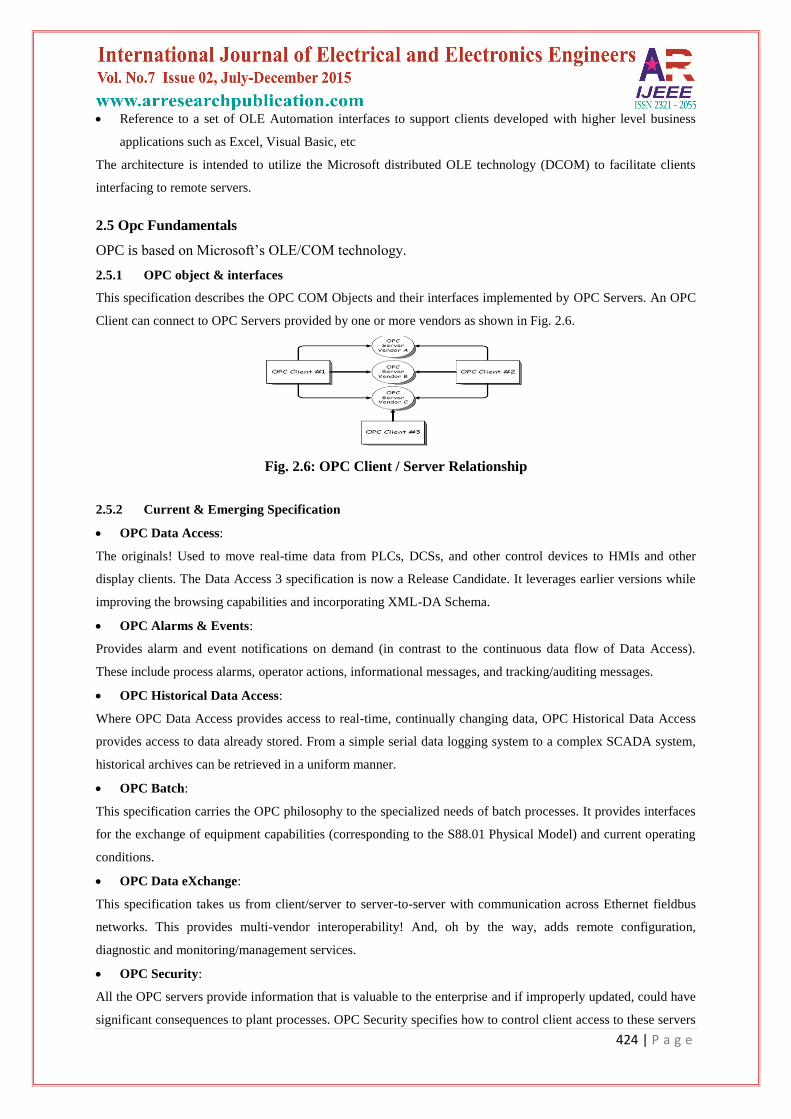
2.5.1 OPC object & interfaces
This specification describes the OPC COM Objects and their interfaces implemented by OPC Servers. An OPC
Client can connect to OPC Servers provided by one or more vendors as shown in Fig. 2.6.
Fig. 2.6: OPC Client / Server Relationship
2.5.2 Current & Emerging Specification
OPC Data Access:
The originals! Used to move real-time data from PLCs, DCSs, and other control devices to HMIs and other
display clients. The Data Access 3 specification is now a Release Candidate. It leverages earlier versions while
improving the browsing capabilities and incorporating XML-DA Schema.
OPC Alarms & Events:
Provides alarm and event notifications on demand (in contrast to the continuous data flow of Data Access).
These include process alarms, operator actions, informational messages, and tracking/auditing messages.
OPC Historical Data Access:
Where OPC Data Access provides access to real-time, continually changing data, OPC Historical Data Access
provides access to data already stored. From a simple serial data logging system to a complex SCADA system,
historical archives can be retrieved in a uniform manner.
OPC Batch:
This specification carries the OPC philosophy to the specialized needs of batch processes. It provides interfaces
for the exchange of equipment capabilities (corresponding to the S88.01 Physical Model) and current operating
conditions.
OPC Data eXchange:
This specification takes us from client/server to server-to-server with communication across Ethernet fieldbus
networks. This provides multi-vendor interoperability! And, oh by the way, adds remote configuration,
diagnostic and monitoring/management services.
OPC Security:
All the OPC servers provide information that is valuable to the enterprise and if improperly updated, could have
significant consequences to plant processes. OPC Security specifies how to control client access to these servers
425 | P a g e
in order to protect this sensitive information and to guard against unauthorized modification of process
parameters.
OPC XML-DA:
Provides flexible, consistent rules and formats for exposing plant floor data using XML, leveraging the work
done by Microsoft and others on Web Services.
OPC Complex Data:
A companion specification to Data Access and XML-DA that allows servers to expose and describe more
complicated data types such as binary structures and XML documents.
OPC Commands:
A Working Group has been formed to develop a new set of interfaces that allow OPC clients and servers to
identify, send and monitor control commands which execute on a device.
OPC Unified Architecture:
A new set of specifications that are not based on Microsoft COM that will provide standards based cross-
platform capability.
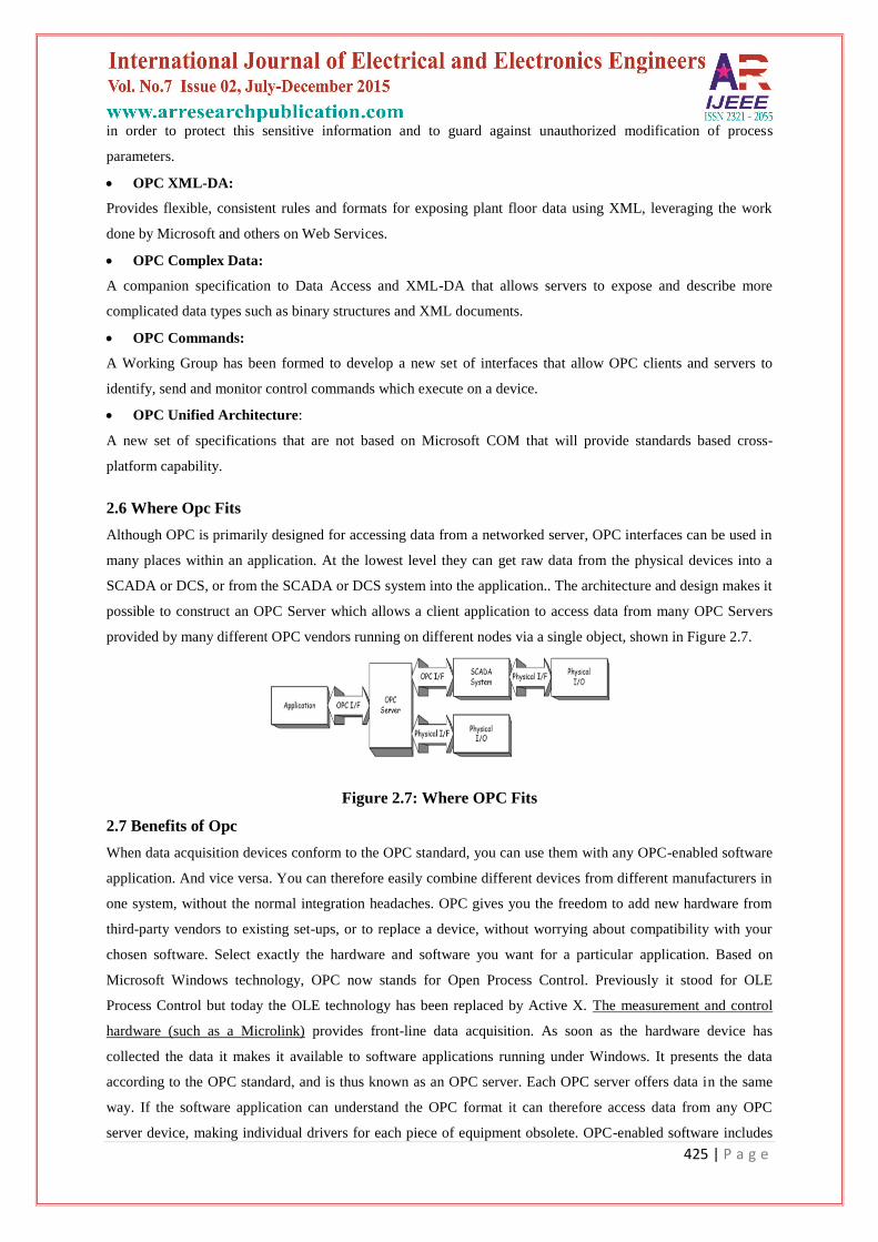
2.6 Where Opc Fits
Although OPC is primarily designed for accessing data from a networked server, OPC interfaces can be used in
many places within an application. At the lowest level they can get raw data from the physical devices into a
SCADA or DCS, or from the SCADA or DCS system into the application.. The architecture and design makes it
possible to construct an OPC Server which allows a client application to access data from many OPC Servers
provided by many different OPC vendors running on different nodes via a single object, shown in Figure 2.7.
Figure 2.7: Where OPC Fits
2.7 Benefits of Opc
When data acquisition devices conform to the OPC standard, you can use them with any OPC-enabled software
application. And vice versa. You can therefore easily combine different devices from different manufacturers in
one system, without the normal integration headaches. OPC gives you the freedom to add new hardware from
third-party vendors to existing set-ups, or to replace a device, without worrying about compatibility with your
chosen software. Select exactly the hardware and software you want for a particular application. Based on
Microsoft Windows technology, OPC now stands for Open Process Control. Previously it stood for OLE
Process Control but today the OLE technology has been replaced by Active X. The measurement and control
hardware (such as a Microlink) provides front-line data acquisition. As soon as the hardware device has
collected the data it makes it available to software applications running under Windows. It presents the data
according to the OPC standard, and is thus known as an OPC server. Each OPC server offers data in the same
way. If the software application can understand the OPC format it can therefore access data from any OPC
server device, making individual drivers for each piece of equipment obsolete. OPC-enabled software includes

426 | P a g e
spreadsheets, databases, virtual instruments and SCADA (supervisory control and data acquisition) interfaces.
These applications are known as OPC client software. You can also develop your own Visual Basic programs to
exchange data with OPC servers. Your program will work with all OPC devices connected to your PC and on
the network. Each OPC server can simultaneously provide data for any number of OPC clients. Likewise
multiple clients can at the same moment access any server: a robust method of communication. With OPC,
measurement and control systems can share information and co-operate with other installations across factories,
offices, laboratories, etc. The same data is therefore readily available to engineering, maintenance,
management...in fact to anyone that requires up-to-the-minute data on which to base their decisions.OPC allows
"plug-and-play". All OPC devices will connect together and immediately work with the OPC client software.
This has the potential to massively reduce installation and system configuration time. It also means that you can
add devices without shutting down existing systems.
III. ICONICS MODBUS OPC SERVER 3.1
3.1 Introduction
The ICONICS Modbus OPC Server 3.1 is an OPC-compliant server that serves data to OPC clients. The
Modbus OPC server was implemented using advanced programming concepts of the current version of the OPC
specification for use in developing next generation industrial software applications.
Key features of the Modbus OPC Server 3.1 include:
Flexible configuration for numerous tags.
Tag values are persistent.
Tags can be grouped in logical folders for manageability.
Tags support configurable range information.
Tags have configurable alarm conditions.
Tag multiplier allows you to create hundreds of tags in seconds.
Supports OPC Data Access (DA) and Alarm and Events (AE) specifications.
OPC XML-DA wrapper installs with Modbus OPC Server
TraceWorX32 diagnostics support (logging data into XML file)
Sample OPC Client
OPC Admin Utility
The Modbus OPC Server product contains two parts: a user interface configuration module and the actual OPC
server, the runtime module. The configuration module allows you to create a database that holds configuration
data of the tags. Such as the tag name, the ranging, and the alarm settings. The runtime module uses a runtime
database to access the actual values of the tags configured. Structures of both databases are indicated in the
following sections. Changes made to the configuration are accepted only after a restart of the OPC server.
However, changes made to the runtime database are accepted online.
3.2 Modbus Configurator
The screen consists of a split window with a tree control view in the left-hand pane and a configuration view in
the right-hand pane. The installation provides a default, configured Microsoft Access database file
427 | P a g e
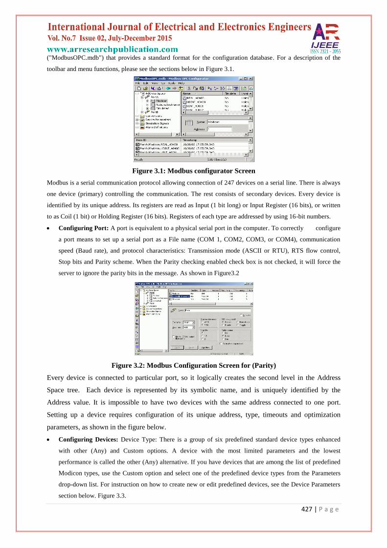
("ModbusOPC.mdb") that provides a standard format for the configuration database. For a description of the
toolbar and menu functions, please see the sections below in Figure 3.1.
Figure 3.1: Modbus configurator Screen
Modbus is a serial communication protocol allowing connection of 247 devices on a serial line. There is always
one device (primary) controlling the communication. The rest consists of secondary devices. Every device is
identified by its unique address. Its registers are read as Input (1 bit long) or Input Register (16 bits), or written
to as Coil (1 bit) or Holding Register (16 bits). Registers of each type are addressed by using 16-bit numbers.
Configuring Port: A port is equivalent to a physical serial port in the computer. To correctly configure
a port means to set up a serial port as a File name (COM 1, COM2, COM3, or COM4), communication
speed (Baud rate), and protocol characteristics: Transmission mode (ASCII or RTU), RTS flow control,
Stop bits and Parity scheme. When the Parity checking enabled check box is not checked, it will force the
server to ignore the parity bits in the message. As shown in Figure3.2
Figure 3.2: Modbus Configuration Screen for (Parity)
Every device is connected to particular port, so it logically creates the second level in the Address
Space tree. Each device is represented by its symbolic name, and is uniquely identified by the
Address value. It is impossible to have two devices with the same address connected to one port.
Setting up a device requires configuration of its unique address, type, timeouts and optimization
parameters, as shown in the figure below.
Configuring Devices: Device Type: There is a group of six predefined standard device types enhanced
with other (Any) and Custom options. A device with the most limited parameters and the lowest
performance is called the other (Any) alternative. If you have devices that are among the list of predefined
Modicon types, use the Custom option and select one of the predefined device types from the Parameters
drop-down list. For instruction on how to create new or edit predefined devices, see the Device Parameters
section below. Figure 3.3.

428 | P a g e
Timeouts: Timeout parameters (separately for reading and writing data) specify the period of time (in
milliseconds) the server will wait for a response from the device.
Optimizations: The server tries to optimize the communication with the devices by requesting as much
data as possible in one message. Consecutive registers are merged together into one request for efficiency.
The server also can read registers that are not really requested, if this allows it to join two blocks of
requested registers. The numbers entered under Optimizations specify the maximum block length of
adjacent unused data.
A Data Item represents a register in the device or a range of registers. A symbolic name and description is
associated with the data item. An OPC client can obtain the data item description. The actual OPC item
name (tag) is compounded from the Address Space root, the names of the folder and its subfolders, and the
name of the data item. Data items can be located in any folder, even in the root of the address space.
Address Space Logical Data Item: Name: A logical name for the data item (Setpoint, Param001,
ON_OFF, etc).
Description: A descriptive comment for the data item. Location
Type: Location type is a type of a register in the device. Device registers are divided into Coils, Inputs,
Input Registers and Holding Registers.
Modbus Type: The location type (device data) will be understood as Modbus type (OPC data type).
Modbus data type also depends on the Location type selected Example: Coil or Input (1 bit) device data
type could be Modbus BOOL only. When selecting Modbus String type, you must specify the data length
(how many bytes will the String is represented by).
Figure 3.4: Address Space Logical Data Item
Simulation: To test the client functionality, choose a Simulation Signal from the Signal drop-down list
and check the Simulate check box. See the Simulation Signals section for information about creating
simulation signals. All levels in the Address Space (port, device, folder, data item) support the process
of simulation (Simulate check box). The parent list in the tree is superior; it has a higher priority when
deciding to simulate the data item or not. In other words, a data item is simulated, if it itself has a
simulation selected, or if any of its parents has the Simulate check box checked. (It may be simulated
even if its Simulate check box stays unchecked)Manual: If checked, the data item will offer constant
parameter value, because Manual setting is of the highest priority. The changes in the configuration
take effect only when the server reloads the configuration (on startup).
Starting Address: This value specifies the data item address (register number) in the device data
space. With the UINT Modbus type, it is possible to extract bits from the register and use them as a
429 | P a g e
Boolean or integer value (this functionality is read-only). You can specify a group of Count adjacent
bits inside a word starting with Bit #. This way, it is possible to use a register for several separate data
items.
Use Conversion: To get the data value converted according to a prescribed form, choose one of the
predefined or user-defined conversions. See the "Conversions" section for more details.
Generate Alarms: Check the Generate Alarms check box to make the server generate alarms based on
the data item value. The Message Prefix parameter is the text of the message for this data item; it will
be followed by the text configured for a particular alarm type. The second part of the alarm message
will contain the Message Body string (see Alarm Definitions). The server allows having any number of
alarm definitions (templates) predefined. You can then combine one of them with the specific tags.
Monitoring View: The Configurator includes a runtime monitor for viewing server data. To change to
the monitor view, select Monitor View from the View menu. The runtime monitor appears in the
bottom pane of the Configurator screen, as shown in the figure below (Figure 3.5). During runtime, the
monitor scans the server and displays the tag values and other statistics such as date, time, and quality.
Monitoring is enabled for each item with a check mark next to it. To enable/disable monitoring for an
item, you can click on the box to the left of the item. A check mark inside the box means the item is
enabled for monitoring. If there is no check mark, then the item is disabled.
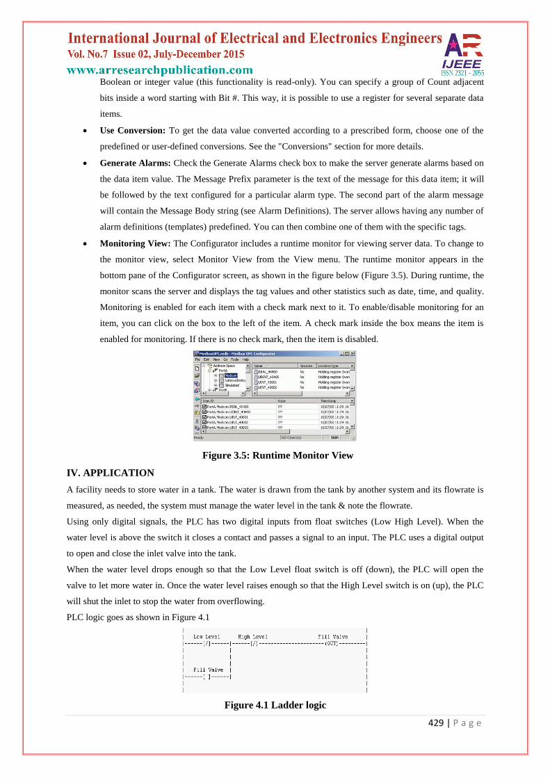
Figure 3.5: Runtime Monitor View
IV. APPLICATION
A facility needs to store water in a tank. The water is drawn from the tank by another system and its flowrate is
measured, as needed, the system must manage the water level in the tank & note the flowrate.
Using only digital signals, the PLC has two digital inputs from float switches (Low High Level). When the
water level is above the switch it closes a contact and passes a signal to an input. The PLC uses a digital output
to open and close the inlet valve into the tank.
When the water level drops enough so that the Low Level float switch is off (down), the PLC will open the
valve to let more water in. Once the water level raises enough so that the High Level switch is on (up), the PLC
will shut the inlet to stop the water from overflowing.
PLC logic goes as shown in Figure 4.1
Figure 4.1 Ladder logic

430 | P a g e
After knowing the control hierarchy and finding total number of I/O’s, logic is prepared in PLC using ladder
editor. After logic is checked by downloading it in PLC the next we have to define its access type as Read(R),
write (W) or Read/write(R/W).Tags with access as read type read the value of tags i.e. 0 or 1 and displayed it,
with access as write changes the value of the tag as 0 or 1. The tag with R/W does both the function. For the said
process program(representation) is developed in SCADA or VB. The value of the tag is fetched from OPC
server and displayed its status on the screen.
V. CONCLUSION
OPC combines different devices from different manufacturers in one system also it reduce installation
time, can add devices without stopping existing software and systems .Quickly replace a device from
one vendor with one from another. Share information around networks. Factory, laboratory and office
applications can all access the same data. Reliable data as any number of OPC software applications
can simultaneously read a device .Single, industry-standard, data interface. Also it is a alternative cost
effective solution to PLC & SCADA system.
REFERENCES
[1]. Swati P. Madhe and Mohini R. Kirane,”Customized SCADA using OPC”,Journal of the Instrument
Society of India,Vol.39 No.3,pp199-201.
[2]. Webb J. Reis. A., 2003,”Programmable Logic Controller”, Prentice-Hall of India Private Limited.
[3]. Kant K., 2002,”Computer Based Industrial Control” , Prentice- Hall of India Private Limited.
[4]. IDC Technologies, “Practical Fieldbus, Devicenet & Ethernet For Industry”