Embed Size (px)
Citation preview

Process Development
Methodology and Implementation Strategy
Thomas Kearney and Robert Collier
Ocean Observatories Initiative College of Atmospheric and Oceanographic Sciences
Oregon State University
August 14, 2009

Page 2 of 55
Table of Contents
1 Introduction ............................................................................................................................................ 4 1.1 Sources of Information ................................................................................................................. 5 1.2 Process Development Methodology ............................................................................................. 5
1.2.1 Common Process Development Tools and Deliverables ..................................................... 5 1.2.2 TOM Process Framework .................................................................................................... 6 1.2.3 Process Development Template .......................................................................................... 6 1.2.4 Process Development Implementation Steps ....................................................................... 7 1.2.5 Common Process Development Methodology .................................................................... 7
1.3 Process Development Goals ......................................................................................................... 7 1.4 Process Development Benefits ..................................................................................................... 8
2 Process Development ............................................................................................................................. 8 2.1 Process Development Context ...................................................................................................... 8
2.1.1 Project Governance and Scope Definition ........................................................................... 9 2.1.2 Best Practice Research ....................................................................................................... 10 2.1.3 Process Automation ........................................................................................................... 10
2.2 Process Development Template (PDT) ...................................................................................... 10 2.2.1 Phase I – Preliminary Process Design ............................................................................... 11 2.2.2 Phase II – Detailed Process Design ................................................................................... 12 2.2.3 Process Development Template Step Descriptions ........................................................... 12 2.2.4 Applying Process Development Template Steps ............................................................... 14
3 Process Development Implementation ................................................................................................ 14 3.1 Process Development Implementation Steps (PDIS) ................................................................. 15 3.2 Process Development Success Factors ....................................................................................... 16
3.2.1 Solidify Process Collaboration Across IOs ....................................................................... 16 3.2.2 Continue to Involve Vendors and End Users .................................................................... 16 3.2.3 Clearly Define Process Objectives .................................................................................... 16 3.2.4 Use Objectives To Focus Process Development ............................................................... 16 3.2.5 Develop a Shared Process Structure .................................................................................. 16 3.2.6 Identify Common Methodology & Tools .......................................................................... 16 3.2.7 Conduct Process Development Team Training ................................................................. 16 3.2.8 Pursue Best Practice Research ........................................................................................... 16 3.2.9 Align Process & Software Development Work ................................................................. 17 3.2.10 Develop Process Performance Metrics ............................................................................ 17 3.2.11 Plan for Transition Management and Training ................................................................ 17 3.2.12 Use an Experienced Process Development Practitioner .................................................. 17
4 Process Development Example - CGSN Sensor Life Cycle ............................................................... 17 4.1 CGSN Process Project Context .................................................................................................. 17
4.1.1 Project Scope ..................................................................................................................... 18 4.1.2 Project Objectives .............................................................................................................. 18 4.1.3 Best Practice Research ....................................................................................................... 18
4.2 CGSN Process Project Deliverables ........................................................................................... 19 4.2.1 CGSN Process Project Team Members ............................................................................. 20 4.2.2 Process Collaboration ........................................................................................................ 20 4.2.3 Process Structure ............................................................................................................... 21 4.2.4 Process Library (Repository) ............................................................................................. 21 4.2.5 Functional Roles ................................................................................................................ 22 4.2.6 CGSN Sensor Life Cycle Process Maps ............................................................................ 23

Page 3 of 55
4.3 Manufacturer Case Studies ......................................................................................................... 26 4.3.1 Manufacturer Selection Process ........................................................................................ 26 4.3.2 Case Study Steps ................................................................................................................ 26 4.3.3 Manufacturer Profiles ........................................................................................................ 27 4.3.4 Typical Service Activities: ................................................................................................ 27 4.3.5 OOI Maintenance Implications for Manufacturer A and B ............................................... 28
4.4 Open Issues ................................................................................................................................. 28 4.4.1 Significant Open Issues ..................................................................................................... 29
5 References ............................................................................................................................................ 31 6 List of Figures ...................................................................................................................................... 32 7 Acronym List ....................................................................................................................................... 33 8 Appendix .............................................................................................................................................. 34
Appendix A: Process Structure & Library ....................................................................................... 34 Appendix B: CGSN Functional Roles (draft) .................................................................................. 35 Appendix C: CGSN Sensor Life Processes ...................................................................................... 36 Appendix D: Open Issues Log ......................................................................................................... 48 Appendix E: Vendor Maintenance Interview Questionnaire ........................................................... 51 Appendix F: Manufacturer Maintenance Use Case ......................................................................... 53 Appendix G: Typical Manufacturer Service Activities .................................................................... 55

Page 4 of 55
1 Introduction This white paper investigates methods to conduct effective and efficient process development within the context of the NSF funded construction of the Ocean Observatory Facility. The basis of this process development investigation was the CGSN Sensor Life Cycle project. During the course of this project the sensor life process was developed with CGSN project team members and sensor manufacturers. Initial process collaboration meetings were also conducted across the OOI organization with the Regional Scale Node (RSN) and CyberInfrastructure (CI) implementing organizations. The CGSN Sensor Life Cycle project provided valuable insights into collaborative process development. The input and feedback from CGSN, RSN, and CI captured during the collaborative process development are reflected throughout this white paper. Process development is defined as creating and implementing business processes--the steps and procedures that govern how resources are used to create products and services that meet the needs of particular customers.1 Process development is part of an extensive body of knowledge often referred to as business process management (BPM). Process development is not new; and there are many existing methodologies. 2-8 This white paper focuses on process development within the context of the Ocean Observatories Initiative (OOI) program. OOI process development faces the same challenges as any large organization: Complex cross functional processes, individual contribution vs. standardization, resistance to changing existing processes, organizational silos of activity, reliance on complex technology, remote locations and virtual teams, scarce project resources, and a diverse customer base. This white paper provides a practical guide and methodology that addresses these challenges. This “how to” guide for process development is comprised of three main components: 1) The Process Development Template, a series of steps for developing processes; 2) the Process Development Implementation Steps, a series of steps for managing process development within an organization; and 3) Step-by-step examples created during the Sensor Life Cycle project that illustrate process development deliverables. An integral part of process development is leveraging existing best practices. During the CGSN Sensor Life Cycle project, best practice organizations and individuals were identified, contacted, and engaged. The CGSN process project team continues to nurture these relationships, and collect and analyze information. The source documents have been placed in the Confluence project repository under CGSN Process Development (pending). The OOI Implementing Organizations (IOs) operations and maintenance strategies refer to a Telecom Operations Map (TOM).9-11 The TOM, a best practices publication developed by the TeleManagement Forum, is a reference framework for categorizing processes. This white paper discusses how the TOM, the Process Development Template (PDT), and the Process Development Implementation Steps (PDIS) complement each other. Together they provide a complete process development methodology. Process development may cross Implementing Organization (IO) boundaries or be contained within an IO. The scale of process development projects range from a simple process involving a few resources, to a complex process executed over many months. This practical process development methodology
Page 5 of 55
accommodates different levels of effort, efficiently and effectively utilizes project resources, and rapidly develops sustainable processes. This white paper may be seen as a “living training document” that can be applied, improved and updated as the OOI process development methodology continues to evolve. The organization of the white paper is as follows. Section 1 provides a general process development methodology overview, and demonstrates the complimentary aspects of the TOM, PDT and PDIS. Section 2 introduces the PDT and describes it in detail. Section 3 provides process development implementation steps that greatly increase the quality, speed, and collaborative nature of process development. Section 4 provides examples of PDT project deliverables, providing insights into understanding the application of the PDT.
1.1 Sources of Information The CGSN Sensor Life Cycle project team conducted thirty-one interviews of CGSN, RSN, and CI project team members. Two sensor manufacturers (WET Labs and Sunburst) were interviewed with regard to their sensor maintenance processes and typical interactions with their sensor customers. The OOI project document repository was utilized extensively. These sources were supplemented by process development literature, sensor manufacturer processes, industry best practices documents, and extensive process development training material used to support enterprise wide process and technology implementations. The Process Development Template (PDT) and Process Development Implementation Steps (PDIS) were utilized and improved during the CGSN Sensor Life Cycle project (version 1.0). The original PDT and PDIS were developed from Improving Performance by G. Rummler, A. Brache (1995) 2, A Guide to the Project Management Body of Knowledge
(PMBOK) 12, Oracle Customer Relationship Management (CRM) training; Nike global process best practices; business process management training; and 15 years of assimilating and applying concepts while leading business process development projects. The PDT and PDIS were used successfully by the author on multiple global cross-functional projects at Nike, Inc. A comprehensive listing of reference material may be found in Section 5 References.
1.2 Process Development Methodology This section describes the basic commonalities between process development methodologies. Also included are descriptive overviews of the Telecom Operations Map (TOM), the Process Development Template (PDT), and Process Development Implementation Steps (PDIS).
1.2.1 Common Process Development Tools and Deliverables Developing the steps and procedures that govern how resources are used to create products and services that meet the needs of particular customers are captured in similar forms by the majority of

Page 6 of 55
process development methodologies. These common elements include, but are not limited to the following tools and deliverables. Common Process Development Tools
Process development objectives & governance Actors and functional roles that perform process activities Process maps (flows) made up of activities Process levels with increasing levels of detail Inputs – activities – outputs analysis Use cases and scenarios
Common Process Development Deliverables
Process structure, process maps (flows) and repository (library) Actor interactions and information interfaces Business rules including triggers, alerts, routing, decision trees, etc. Workflow automation design (reports, interfaces, data capture, and investment priorities) Re-useable activity modules (like clock or compass) Process training material Process performance and user adoption metrics
The TOM and PDT methodologies contain these common elements. The following sections provide a brief overview of each and how these methodologies complement each other.
1.2.2 TOM Process Framework The Telecom Operations Map (TOM) 9-11 was developed by the TeleManagement Forum, an international consortium of communications service providers. The TOM is a reference framework for categorizing the business activities that a service provider will use, in a structured manner that allows the relationship between processes to be captured. The TOM methodology provides a business process framework for developing operations and maintenance processes. The TOM was developed in the mid-1990s by TeleManagement Forum (TMF) with a primary focus on operations processes. The TMF enhanced the TOM model in 2002 by expanding it to include all enterprise processes which created the enhanced TOM or eTOM. This document uses these terms interchangeably.
The OOI Implementing Organizations (IOs) have all adopted a modified version of the TOM process framework in their Operations and Maintenance documentation. This decision leverages best practices and provides a starting point for common process development methodology.
1.2.3 Process Development Template The Process Development Template (PDT) is a standardized series of steps for developing processes using a team based approach. The PDT defines process team structure; defines analysis methods; enables efficient use of staff; provides for stakeholder involvement; and involves management review and subsequent process approval. The PDT is particularly effective for developing processes requiring

Page 7 of 55
collaboration across multiple functional areas and organizations. The PDT section of this white paper provides a detailed “how to” guide for process development.
1.2.4 Process Development Implementation Steps The Process Development Implementation Steps (PDIS) standardized series of steps for managing process development within an organization. The PDIS ensure that process projects operate within the context of organizational priorities. The important contextual aspects of process development are: process development governance; appropriate project staffing; cross functional collaboration; consensus building; team participation; stakeholder involvement; and continuous management of process objectives, priorities, and resource usage.
1.2.5 Common Process Development Methodology The TOM provides a conceptual business process framework for organizing and relating business processes at an enterprise level. The TOM provides a context for process development. The Process Development Template (PDT) provides steps for developing processes. The Process Development Implementation Steps (PDIS) provides steps for managing process development within an organization. Together the TOM, PDT, and PDIS provide a complete process development methodology. This white paper posits this combined methodology be adopted as a common methodology and utilized for process development by CGSN, RSN, CI, and OL. It is also proposes this document be seen as a living document that can be collaboratively applied, improved and updated as a reference and training document. This provides a common methodology which is a critical success factor in organizational process development.
1.3 Process Development Goals The following process development goals are based on the CGSN Sensor Life Cycle project findings: Develop effective processes required to provide a quality OOI data product, which is trusted
and accessible by customers; Provide cost effective O&M services that met or exceed customer expectations;
Enable effective O&M processes by promoting development collaboration across and within
OOI organizations; Implement a common process development methodology which delivers quality, cost effective
and rapid process development; Implement a process development governance structure that prioritizes process development,
provides resources, and resolves issues.

Page 8 of 55
The process development methodology should be easy to use and understand, conserve project resources, rapidly deliver results, and be supported by process development training documentation in the context of the organizational priorities.
1.4 Process Development Benefits The benefits derived from process development result both from the “act” of creating the processes, and the “products” that process development creates. Effective process development: Builds common understanding across partnering organizations and functional teams;
Breaks down silo behaviors by crossing organizational and functional boundaries;
Fosters management, stakeholder, and opinion leader alignment around critical processes;
Motivates team members through team participation;
Enhances team participation and the creation of sustainable processes;
Creates process “champions” which facilitates transition management and training;
Creates performance metrics which enable effective process management;
Enables continuous process improvements by clearly understanding process performance;
Identifies areas of opportunity for process automation and streamlining;
Prioritizes improvements by being able to model changes and apply cost/benefit analysis;
Provides the foundation for essential training materials.
2 Process Development This section introduces the Process Development Template (PDT) and describes in detail how it is sequentially applied. Before the PDT is described, the context within which process development occurs is discussed.
2.1 Process Development Context Any process creation follows a series of steps within a larger context of organizational priorities and constraints. Process development is always conducted in the context of high level objectives and governance structures which prioritize all aspects of process development. The Process Development Template (PDT) assumes that these contextual factors have been taken into account prior to applying the PDT.

Page 9 of 55
The important contextual aspects of process development are: process development governance; appropriate project staffing; cross functional collaboration; consensus building; team participation; stakeholder involvement; and continuous management of process objectives, priorities, and resource usage. Process development may occur in many forums. For example: Process development may be conducted in individual and/or group meetings over a period of time; or in a workshop setting where process development work is compressed. Both methods require substantial pre- and post-meeting work to be conducted successfully. In all settings, basic PDT training is provided to process development team members. Process development may be conducted on many levels, from processes that span entire organizations, to very detailed processes within a single department. Process development may include new processes and/or existing processes. The PDT can be applied to both, with additional steps for existing process improvement projects. These additions include conducting “as is” process analysis; developing the “to be” processes using the PDT, and then performing a “gaps” analysis between “as is” and “to be” processes. Process development implementation success factors are considered in Section 4 Process Development Implementation Steps (PDIS).
2.1.1 Project Governance and Scope Definition Process development occurs within the context of a project. A project has a specific purpose, which when accomplished, completes the project. Effective process development requires the same project management as any project. While project management is not the topic of this white paper, three elements are critical to successful process development: project governance structure, scope definition, and process project leadership. Project Governance Structure: A clearly defined project governance structure provides organizational representation and decision making capabilities. An example governance structure for OOI might include a steering committee made up of a representative from each IO. The steering committee prioritizes process work, allocates resources, and resolves high level process issues. Scope Definition: A scope definition describes major deliverables, project assumptions, and project objectives. The project objectives provide critical guidance during process development management, including continuous alignment of process work to achieve process objectives. Each process project has its own scope statement. Process Project Leadership: Process development projects require project management. OOI has an effective program and project management structure in place. This white paper recommends that process development management be strengthened in the existing project management structure. An example is adding “process development lead” position to facilitate, train, and coordinate process development for cross-functional projects and/or projects that involve multiple IOs.

Page 10 of 55
2.1.2 Best Practice Research Process development takes into account best practices. Each process area being considered for development benefits from best practice research. Sources include expertise within the participating organization, external organizations currently performing similar processes within the same industry, and external organizations currently performing similar processes but in different industries and settings.
2.1.3 Process Automation Process development does not mean process automation. Process implementation may precede software tools and automation. In some cases this allows a true test of the process prior to technology investments. Allowing a process to mature prior to automation reduces system development risk. When possible, it is advisable to evaluate process automation after completing process development. This allows for a more complete cost benefit analysis, prior to technology investments, as the entire process is considered. While identifying process automation is a benefit of process development, significant benefits are realized even without automation.
2.2 Process Development Template (PDT) The Process Development Template (PDT) provides a step by step “how to” guide which effectively and rapidly develops processes using a team based approach. The PDT is comprised of two phases: Preliminary Process Design and Detailed Process Design. Each phase contains seven process design steps. The PDT steps may be repeated multiple times. It is an iterative process which is generally completed when the process objectives have been attained. See Figure 1: Process Development Template. The process development team structure is an essential component of applying the PDT. Process quality, development speed and stakeholder involvement result from the PDT process team structure. The process team is made up of expert representatives from each impacted functional area. The process team is empowered to represent their area, make process design decisions, and is required to keep their stakeholders aware of decisions. This process team structure provides two important benefits. First it allows a focused team of individuals to become intimately familiar with the process and issues. Second it creates vital communication channels between process team members and their stakeholders. In this section the two PDT phases and the fourteen detailed steps are described in detail.

Page 11 of 55
This diagram shows a graphical representation of the Process Development Template.
Figure 1: Process Development Template.
2.2.1 Phase I – Preliminary Process Design Phase I delivers a preliminary process design document which is reviewed and approved by stakeholders prior to beginning Phase II. During Phase I, subject matter experts (SME) are identified and interviewed by a process development practitioner. This process analysis pre-work identifies key functional roles involved in the process. It also provides a draft strawman process. This completes the first three steps in Phase I. This process analysis pre-work is completed prior to the process team member selection and involvement. This is for two reasons: A high level process understanding assists in team member selection and a draft strawman process is prepared for the first team review. An important aspect of Phase I is conducting process development using the 80/20 rule. During process analysis both normal and exception process attributes are identified. Normal attributes are associated with the expected or best case process flow. Exception attributes are associated with process anomalies. Generalizing, the 80% represents the normal or mainstream process, the 20% represents the exceptions. During process development, process attributes that fall into the 20% category are captured as open issues and deferred until Phase II allowing the 80% main stream process work to drive design decisions. Another important aspect of Phase I is that time and resource constraints are largely ignored, within reason, until Phase II. This allows the end-to-end process design to be completed prior to working on improvements that may not be in context. These methods also allow the process team to move ahead more effectively.

Page 12 of 55
The completion of Phase I occurs when a formal management process review is conducted, and approval to proceed is granted. This ensures stakeholders are aligned prior to further resource investments.
2.2.2 Phase II – Detailed Process Design During Phase II process enablers are identified within the context of the process objectives and constraints. Process enablers may include technology support, reports, detail information exchanges, data interfaces, organizational structure and staffing levels. These enablers and resource needs are identified and negotiated in Phase II. As the process becomes more robust and resource capabilities are added, estimated workflow loads are modeled through the process flow. For example: The number of sensors and platforms that need to be serviced during a maintenance period. Issues are identified and resolved on a regular basis. Process automation, technology investments, resource and staffing allocations may need to be adjusted to achieve the process objectives. Finally, a formal management process sign off occurs prior to implementation.
2.2.3 Process Development Template Step Descriptions This section describes each of the fourteen steps in the PDT. A common activity in each step is to capture open issues. A general description of each step follows. Figure 1: Process Development Template shows a graphical representation of the PDT steps. 1. Interview Subject Matter Experts (SME): Based the process development context, SMEs are
selected for interviews. They have intimate knowledge of the process area under consideration. Questionnaires are usually helpful in the interview and in capturing information for later analysis. See Appendix E: Vendor Maintenance Interview Questionnaire.
2. Draft Functional Roles: Based on the interviews and process development context, draft functional
roles are developed. These are roles (actors) perform process activities. Different functional roles may be performed by the same person (job). A number of roles may be combined into a job position description; these in turn may be assigned to a department or functional group within an organizational structure. (See PDT step 10 Define/Modify Organizational Structure)
3. Draft Strawman Processes: Based on the interviews, process development context, and functional
roles, the process development practitioner drafts strawman processes. These can also be created in a participative manner in a group setting, for example creating a strawman process using sticky notes to define and organize process activities into a process flow.
4. Identify Process Design Owners: Process design owners form the most critical component of the
process project team. They are expert users from each functional area and are empowered to represent their area, make process design decisions, and keep their stakeholders aware of decisions.

Page 13 of 55
This structure provides two important benefits. First it allows a team of people to become intimately familiar with the process and issues. Second it creates vital communication channels between process team members and stakeholders.
Process Design Owner roles are related to process development, the process team dissolves once the project is complete. Operational Process Owner roles are related to the process after project is complete. They manage operational processes, report on process performance metrics, and conduct process reviews & improvements.
5. Review Draft Processes: The process design owner team reviews the draft processes making
improvements and identifying open issues. 6. Align with Process Objectives: Based on the process development context, process design is
aligned with the process objectives. Performance metrics that reflect and quantify the project objectives are developed. These measurable variables indicate the effectiveness and efficiency of the process. They are also a critical assessment and reporting tool in ensuring process sustainability, user adoption, and process improvements after the process is implemented.
7. Identify & Resolve Open Issues: Open issues are constantly being identified during a project. Each
issue is recorded, prioritized, and assigned for resolution. The issues log becomes a key project management tool and information repository. Closed issues and their resolution provide a wealth of information for training and new team member orientation. See Appendix D: Open Issues Log.
8. Identify & Interface Requirements: During process development, reports and interface
requirements are identified. A detailed step in process design involves defining individual process activities. These take the form of inputs / activities / outputs. A series of related activities make up a process. Frequently these inputs and outputs involve information required by the process activity. This required information, provides report and interface requirements.
9. Incorporate Cycle Time Constraints: Until now process development has been conducted without
rigorous time constraints. Based on the process development context, time constraints are added. This constraint may result in a number of issues being identified. These types of issues may be resolved at later steps through staffing, process automation, and resource allocation.
10. Define/Modify Organizational Structure: Based on the process development context, and the
functional roles defined earlier, roles are combined into job position descriptions and assigned to a functional group. These functional groups are placed in an organizational structure. If an organizational structure already exists, modifications may be made based on process capability requirements.
11. Incorporate Staffing Model & Resource Plans: Based on the process development context and
previous process work, staffing models are developed. These models are based on anticipated process through put (volume of work over time) and the process capacity. The resource, labor or material, required to meet the process objectives, is estimated for each process activity. Cost benefit analysis of resources, process automation and process scope reduction are considered.
12. Test Process Through Put: Based on anticipated volume of work over time and process capacity,
the process is tested / modeled from start to finish. Open issues are identified.

Page 14 of 55
13. Identify & Resolve Open Issues: Each issue is recorded, prioritized, and assigned for resolution based on the process development context. An iterative review of open issues is undertaken during process design using process objectives as a guide for resolution. Upstream process development steps are revisited until process objectives are met.
14. Management Process Sign Off: Process Design Owners formally present the process for their
management stakeholder sign off. Ideally, there are no surprises for the stakeholders as they have been consulted during process development.
2.2.4 Applying Process Development Template Steps The process development template steps are applied in a suggested sequence. Each project will have unique opportunities and constraints that may impact the process development order, the depth of process analysis at each step, and the number of time each step is re-visited. The number of processes being developed also impacts the application of the PDT. For example: In a large process project a set of interrelated processes may be developed in tandem, all completing Phase I prior to moving to Phase II. Process development is guided by objectives described in the process project scope document. Effective process team management requires constant alignment of process work to achieving process objectives.
3 Process Development Implementation The Process Development Implementation Steps (PDIS) focuses on managing process development and ensuring that the process projects operate within the context of organizational priorities. The important contextual aspects of process development are: process development governance; appropriate project staffing; cross functional collaboration; consensus building; team participation; stakeholder involvement; and continuous management of process objectives, priorities, and resources. Section 4 provides step by step description of the PDIS. This section also includes process development success factors. When applied these increase the quality, speed, and collaborative nature of process development. The Process Development Template (PDT) is a guide for developing processes. The PDIS is a guide for managing process development. Together the PDT and the PDIS create a process development methodology. The TOM provides a conceptual business process framework for organizing and relating business processes at an enterprise level.

Page 15 of 55
3.1 Process Development Implementation Steps (PDIS) While each project has unique characteristics and circumstances, the following steps have been used by the author to enhance the success of process project implementations.
1. Provide process development governance 2. Prioritize the processes 3. Create the process project team (specific to the top priority process) 4. Enhance the process project objectives 5. Develop the specific process 6. Prioritize the process automation and streamlining opportunities 7. Repeat Cycle
Figure 2: Process Development Implementation Steps
ProvideGovernance
Prioritize Processes
CreateProcess Team
Enhance Process
Objectives
DevelopProcess
Prioritize Process
Improvements
RepeatCycle
. Process Development Implementation Steps – Detailed Descriptions
1. Provide process development governance: A permanent program level steering committee and IO level process managers define organizational objectives, prioritize projects, and resolve high level process issues. In addition, based on the needs of each individual process project, management stakeholders are added to the governance structure.
2. Prioritize processes: Processes are prioritized on a regular basis from a program importance and urgency perspective. Processes may cross IO boundaries or be contained within an IO. The emphasis of this white paper focuses on cross IO process development, although this methodology may be applied to process that are contained within an IO with relatively minor adjustments.
3. Create the process project team: Once the top priority process has been identified, the project
team is staffed. Initially subject matter experts (SMEs) are added to the project team (see PDT Step #1). Subsequently process design owners are added to the team. Process design owners form the most critical component of the process project team (see PDT Step #4).
4. Enhance the process project objectives: Program level process objectives have already been
defined. The process project team adds additional detail based on their knowledge and perspective. These enhanced objectives guide process development.
5. Develop the specific process: The process design team applies the Process Development
Template (PDT) steps to develop the prioritized process.
6. Prioritize the process automation and streamlining opportunities: Using process analysis the process design team identifies workflow bottlenecks, proposes process improvements, while applying cost/benefit analysis to determine improvements with the highest value. This provides

Page 16 of 55
a valuation for process automation and streamlining opportunities. This process analysis is performed in Phase II of the PDT, Step 11: Incorporate Staffing Model & Resource Plans.
7. Repeat Cycle: The process development team completes the GSN Process Template steps for
the prioritized process and is dissolved. A new process development cycle begins.
3.2 Process Development Success Factors In addition to the recommended process development implementation steps described above, supporting process development success factors, include but are not limited to:
3.2.1 Solidify Process Collaboration Across IOs: Collaborative process development enables success through coordinated efforts across organizations 3.2.2 Continue to Involve Vendors and End Users: Vendors and End Users play a critical role in process development. Significant efforts should be made to keep their participation and project engagement at a high level. 3.2.3 Clearly Define Process Objectives: Process development is conducted in the context of high level objectives and governance structures which prioritize all aspects of process development. These objectives are provided by the process project steering committee described above. 3.2.4 Use Objectives To Focus Process Development: Effective process team management requires constant alignment of process work to achieving process objectives. These objectives define the significance and priority of the process to the program, which in turn defines the focus, scope, and level of detail of the process analysis and design. 3.2.5 Develop a Shared Process Structure: Using the eTOM business process framework, reach program level consensus on process structure including process naming, definitions, levels, and roles/actors. 3.2.6 Identify Common Methodology & Tools: Define and utilize consistent process development methods and process tools, including: Define process mapping formats Define levels and detail included Define Input / Activity / Output diagrams Process performance metrics & scorecards Process capture documentation tools Common process documentation repository
3.2.7 Conduct Process Development Team Training: Training each process development team on process tools and methodology to maximize process development effectiveness and efficiency. Identify “process champions” to facilitate transition management and training. 3.2.8 Pursue Best Practice Research: Target three best practice research areas: From within OOI team, within marine industry, and from external high capability organizations. Process

Page 17 of 55
development leaders collect, assimilate, synthesis, and utilize best practices in the following areas: Processes, policy and procedures System automation, software used Training and transition management Process performance management
3.2.9 Align Process & Software Development Work: Foster a partnership between the process development team and CI to a prioritize process and workflow automation opportunities and align work release dates. Process developments projects help prioritize work to be included in software system releases. 3.2.10 Develop Process Performance Metrics: Reporting for process management serves two purposes. Identifying process performance and measuring user adoption success. Both are required for maintaining sustainable processes and identifying areas for process improvement 3.2.11 Plan for Transition Management and Training: Evaluating the degree of change and the adaptability and resilience of the entity being changed are required to gauge the degree of effort required in transition management and training. A plan is developed based on these factors. 3.2.12 Use an Experienced Process Development Practitioner: Managing effective process development is an “art” as well as a science. Utilizing an experienced process development practitioner increases process design quality and reduces process team staff time requirements.
4 Process Development Example - CGSN Sensor Life Cycle The Sensor Life Cycle Process was developed with CGSN project team members and sensor manufacturers. Initial process collaboration meetings were conducted with Regional Sensor Network (RSN) and CyberInfrastructure (CI). The input and feedback from CGSN, RSN, and CI are reflected in these example process development deliverables. The Process Development Template (PDT) was utilized during the CGSN Sensor Life Cycle project (version 1.0). This section uses the CGSN Sensor Life Cycle project scope, objectives, and deliverables to provide illustrative examples that demonstrate the application of the PDT. Section 3.1 show an example of project context including: project scope, objectives, and best practice research. Section 3.2 provides examples of process development deliverables. The examples shown are for illustration purposes only and should not be considered complete nor approved by OOI management.
4.1 CGSN Process Project Context This section provides examples of process development context, including project scope, project objectives, and best practice research.

Page 18 of 55
4.1.1 Project Scope The CGSN Sensor Life Cycle project scope was defined as: Create a Sensor Life Cycle process applicable to any sensor deployed on moored platforms in
the OOI CGSN Endurance Array, with a focus on sensor maintenance processes; Validate the CGSN maintenance process from a process management perspective by
collaborating with OOI project team members and two sensor manufacturers (WET Labs and Sunburst);
Deliver an initial draft of the CGSN Sensor Life Cycle process, and a consultants report
summarizing the project process and results, with recommendations for future improvements by June 15, 2009.
4.1.2 Project Objectives The CGSN Sensor Life Cycle project objectives included: Design and validate O&M processes with stakeholders;
Incorporate best practices;
Provide information for resource management, including staffing models, service level
agreements and inventory management; Provide information for software design, including process maps, roles, supporting reports, and
workflow rules; Facilitate process development collaboration across IOs, including communication, consensus
building, and usage of common methodology and process tools.
4.1.3 Best Practice Research The CGSN process team took a three-pronged approach to best practices research for operations and maintenance (O&M) of the CGSN sensor network. All organizations and individuals that were approached indicated a willingness to collaborate and share best practices. The first part of the three-pronged approach was to research existing marine sensor network expertise from members within the OOI project team. The second approach was to utilize best practices from non-OOI maintenance providers. The third source of best practices is non-OOI non marine organizations. For example Goddard Space Center, NASA, and the Telecom industry.

Page 19 of 55
Existing Network Best Practices (OOI) There are many best practice resources within the OOI project team. These include, but are not limited to the following organizations.
WHOI Bob Weller, Al Plueddeman, John Kemp SIO Frank Vernon UW John Delaney, Deb Kelley, Mike Kelly
As future O&M processes are developed, these individuals (and others not mentioned) have made and continue to make valuable best practice contributions. Existing Network Best Practices (Non-OOI) The following organizations are engaged in the sharing of best practice information. Status to date: Organizations identified; contacts and relationships built; mission embraced. Project team continues to collect and analyze information. The source documents have been placed in the Confluence project repository under CGSN Process Development.
NDBC Dr Chung-Chu Teng * CSIRO David Hughes NURC Alan Sheppard
* NDBC provided O&M documentation to the CGSN project team and continues to be very responsive and cooperative. These best practices will be included in the ongoing O&M process analysis.
4.2 CGSN Process Project Deliverables The Process Development Template (PDT) was applied by the CGSN process team to create draft Sensor Life Cycle process deliverables. The examples included in this section and the appendixes are for illustration purposes only and should not be considered complete nor approved by OOI management. This section provides examples of Sensor Life Cycle project deliverables, including: Project Team Process Collaboration Process Structure Functional Roles Process Maps Open Issues Log Use cases

Page 20 of 55
4.2.1 CGSN Process Project Team Members Team members provided invaluable assistance defining the project organization and project priorities, process and procedures, and developing the CGSN sensor life cycle processes. Team Members include:
Bob Collier CGSN Deputy Project Manager Ed Dever CGSN Project Scientist and Engineer Libby Signell CGSN Program Manager Ian Walsh VP Operations, Manufacturer: WET Labs Julie Rodriguez Service Manager, Manufacturer: WET Labs Jim Beck President, Manufacturer: Sunburst Tom Kearney Process Lead Mike Kelly RSN Best Practices – Advisory Role Al Plueddeman CGSN Best Practices – Advisory Role Mathew Arrott CI Best Practices – Advisory Role
4.2.2 Process Collaboration There are three implementing organizations are involved in the CGSN Sensor Life Cycle process: CGSN, RSN, and CI. CGSN is comprised of three organizations: WHOI, OSU, and SIO. A critical deliverable was process collaboration across IOs, including O&M process review, promoting usage of common methodology and process tools, facilitating communication and consensus building. Onsite process collaboration meetings were conducted, including: RSN: Seattle, UW May 19, 2009. Attending: John Delaney, Peter Barletto, Mike Kelly, Debbie
Kelley, Michael Harrington, and Brian Ittig. CI and SIO: San Diego, UCSD June 1, 2009. Attending: Mathew Arrott, Michael Meisinger,
and Frank Vernon. WHOI: Corvallis, OR, June 18, 2009. Attending: Bob Weller, Libby Signell, and Bob Collier.
Two sensor manufacturers (WET Labs and Sunburst) participated in O&M process
collaboration meetings. They were interviewed with regard to their sensor maintenance processes and typical interactions with their sensor customers. They also participated in strawman process review sessions. Sunburst participated via teleconference.
All participants strongly agreed that collaborative process development was essential.

Page 21 of 55
4.2.3 Process Structure The CGSN Process Team defined three levels of detail (process decomposition) based on the project objectives and project scope. Each process is identified by a prefix using the process level. This numbering sequence makes it clear which process level is being reviewed, and which higher level processes it is related to. It should be noted that the TOM process methodology adopted by the OOI project, may use a different numbering scheme, but this is easily adjusted. The description of each level follows:
Level 1: Based on a complete lifecycle process. An example is the Sensor Life Cycle which starts at research objectives and finishes at sensor decommission. Level 2: Based on process that completes an entire Level 1 process step. An example is Sensor Maintenance. Level 3: Based on process that completes an entire Level 2 process step. An example is Create Maintenance Plan.
4.2.4 Process Library (Repository) The process library is an organized listing processes based on process relationships. The OOI process library provides a hierarchical process listing, process development status, and links to supporting documents. This process library shows an example library structure. Eventually all the OOI processes would be listed, including completed and pending development processes. (See Appendix A: Process Structure & Library.) CGSN Process Library
Figure 3: Process Library

Page 22 of 55
4.2.5 Functional Roles Based on the interviews and process development context, draft functional roles were developed. These are roles (actors) perform process activities. Different functional roles may be performed by the same person (job position). Sixteen functional roles were identified and reviewed by CGSN project management; they are currently in draft status. (For a full listing See Appendix B: CGSN Functional Roles.) The functional roles drafted by the CGSN project team align with the OOI operational domains.
Figure 4: Draft Functional Roles

Page 23 of 55
4.2.6 CGSN Sensor Life Cycle Process Maps This section shows examples of process maps at levels 1, 2, and 3. They are shown here for illustration purposes. Some will not be readable due to space constraints. The complete set of full size process maps developed by the CGSN project team can be found in Appendix C: CGSN Sensor Life Cycle Processes. 4.2.6.1 CGSN Sensor Life Cycle Process (Level 1)
Figure 5: CGSN Level 1 Process: Sensor Life Cycle. Note: Shaded boxes indicate sub-process have been developed. Figure 5 shows a graphical representation of the Sensor Life Cycle Process. The level 2 process steps are described and high level comments are noted. As is often the case, upstream processes provide required information for downstream processes. In this example Step 1.3 Sensor Evaluation is where acceptable performance ranges are established for each sensor. Acceptable performance ranges are used in Step 1.6 Sensor Performance where sensor performance outside acceptable ranges is flagged for maintenance. These flags (trouble tickets) are used in Step 1.7 Sensor Maintenance.

Page 24 of 55
4.2.6.2 CGSN Sensor Maintenance (Level 2)
Figure 6: CGSN Level 2 Process: Sensor Maintenance Figure 6 shows a graphical representation of the Sensor Maintenance Process. The Level 3 process steps are described and high level comments are noted. The blue boxes indicate sub-process have been developed. The full set of process maps developed by the project team can be found in Appendix C: CGSN Sensor Life Processes. 4.2.6.3 CGSN Level 2 Process: Sensor Maintenance Sub-Process Descriptions
1.7.0 Sensor_Platform Maintenance: Describes sensor maintenance process, provides overview and context for sub-processes 1.7.1 Create Maintenance Plan: Describes planning done prior to maintenance. High level of system support indicated. Implications for RSN and Marine IO joint planning. 1.7.2 Maintenance - At Sea: Describes maintenance done on cruise. Implications for “at sea” data capture, including location, sample data, early detection of maintenance needs. 1.7.3 Evaluate Maintenance Need - Marine Ops: Describes assessment, evaluation, and prioritization of maintenance tasks. This has implications for “vendor service and parts requests” and Marine IO resource allocations. 1.7.4 Maintenance - In Shop – Vendor: Describes vendor maintenance process and information communication needs between vendor and OOI. These have implications for data capture and information collaboration software.

Page 25 of 55
1.7.5 Maintenance - In Shop - Marine Ops: Describes internal maintenance process. Sensors are removed, refurbished by vendors, and reattached to platforms. Has implications inventory management.
4.2.6.4 CGSN Level 3 Process: Vendor Maintenance
Figure 7: CGSN Level 3 Process: Vendor Maintenance Figure 7 shows a graphical representation of the Vendor Maintenance Process. The full set of process maps developed by the project team can be found in Appendix C: CGSN Sensor Life Processes. Each circle in the diagram indicates a process point where there is an exchange of information between CGSN and the Vendor. These communication interactions will be common for all vendors. This provides an opportunity for standardizing and possibly automating information exchanges.

Page 26 of 55
4.3 Manufacturer Case Studies The CGSN Sensor Life Cycle process project included interviews with two sensor manufacturers with regard to their internal sensor maintenance processes and customer information needs (external information exchanges). The purpose of this manufacturer case study was to interview sensor manufacturers for maintenance process development and to identify supporting documents used to capture the sensor maintenance information. The case study included two objectives: The first was to determine their internal processes for sensor maintenance, including sensor shipping & receiving, processing capabilities, calibration practices, and inventory strategies. The second objective was to determine OOI and manufacturer information exchange and communication points, including customer contact points, service level agreements, service history, deployment conditions, instrument data, data drift, recalibration, product updates, warranty, and service outside of warranty. The process information obtained has direct application to the Sensor Selection Process and the associated RFP and purchase evaluations.
4.3.1 Manufacturer Selection Process The CGSN selection criteria used to identify the two manufacturers (vendors) for OOI process collaboration included: Recognized as prominent manufacturer of type of sensors to be deployed by OOI Manufacturer of an Optical or Wet Chemical sensors, each type presents unique O&M issues Representative of typical sensor company size – one small and one medium size Willingness to participate with OOI project team members Attended the OOI Vendor Workshop held in Portland (March 09)
Manufacturer and sensors selected:
WET Labs for the Optical sensor: FLNTU Combo Fluorometer and Turbidity Sensor 13-15 Sunburst Sensors for the wet chemical: SAMI-pH Seawater 16-17
4.3.2 Case Study Steps The CGSN team increased the productivity of the manufacturer meetings by following these steps.
Step 1: A questionnaire was sent to each manufacturer prior to process reviews which identified strawman functional roles and process steps for the new Maintain Sensor – Vendor process. The questionnaire increased the initial meeting productivity.(Appendix E: Vendor Maintenance Interview Questionnaire.) Step 2: Meetings with manufacturer subject matter experts to conduct a detailed walk through of the sensor maintenance process. This detailed information can be referred to as a use case or

Page 27 of 55
activity input-output analysis or process decomposition. See Appendix F: Manufacturer Maintenance Use Case. Step 3: Meetings with manufacturer subject matter experts to review and update strawman process. See Appendix C: CGSN Sensor Life Processes; 1.7.4 Maintenance - In Shop – Vendor.
It should be noted that this work is in progress with initial process reviews conducted by CGSN and RSN team members completed. Additional process development and levels of detail are required.
4.3.3 Manufacturer Profiles WET Labs Profile (Manufacturer A): A medium sized company with 45 employees that designs, manufactures, and provides service for a relatively diversified product line of marine sensors. Manufacturer A has automated customer contact, service history, and inventory tracking systems. Maintenance workflow is handled by a diversified staff which utilizes systems to coordinate efforts and manage maintenance process. Sunburst Sensors Profile (Manufacturer B): A small sized company with less than 10 employees that designs, manufactures, and provides service for a limited product line of marine sensors. Manufacturer B has manual customer contact, service history, and inventory tracking systems. Maintenance workflow is handled by a small staff.
4.3.4 Typical Service Activities: The CGSN project team worked with the manufacturers to identify typical manufacturer service activities and internal documents with regard to Sensor Maintenance for their customers. These activities and documents include:
Service Event (list of what is expected maintenance for a specific sensor) Service Request (form customer uses to request services). For example a checklist or web page Service Procedure (steps to be performed). For example remove casing or check pump Service Description (services provided, perhaps an invoice). For example: reagent replenishment, or instrument certification.
WET Labs: See Appendix G: Typical Manufacturer Service Activities (Currently Under Development) Sunburst Sensors: See Appendix G: Typical Manufacturer Service Activities (Currently Under Development)

Page 28 of 55
4.3.5 OOI Maintenance Implications for Manufacturer A and B Based on the maintenance service capabilities, OOI sensor maintenance requirements may impact the manufacturer organizations. The following s provides examples for both medium (A) and small (B) service vendors.
Manufacturer A: Has a higher potential service volume due to their size and systems. If OOI requires data entry to support vendor maintenance process may cause redundant data entry. May be able to interface data directly to OOI systems (establish standard communication protocol). Manufacturer B: May need significant advance maintenance planning to increase staff, or increase inventory (sparing) to accommodate large sensor maintenance influx. If OOI requires data entry to support vendor maintenance process benefit vendor by eliminating paper system (assumes vendor would have access to data).
4.4 Open Issues As process interviews and development progresses, open issues are captured in an Issue Log. Very often, the Issue Log guides process review sessions. As the team walks through the process, they address and resolve issues thereby refining the process. The Issue Log describes the issue, provides issue management tracking including issue assignment, priority, status, and reference to each process step. When an issue is resolved, the resolution is documented. These resolutions provide important process decision making background and are an excellent source of training material for new project team members and process user training. The CGSN project team recorded 117 issues during this initial process development project. (See Figure 8: Issues Log.) Example Open Issues Log is below. For a complete issues log listing see Appendix D: Open Issues Log.
Figure 8: Issues Log

Page 29 of 55
4.4.1 Significant Open Issues During the manufacturer interviews and the CGSN Sensor Life Cycle process development a number of significant realizations were discovered. These issues most likely have been raised and discussed in other forums. While these issues are specific to this process, they demonstrate the range and importance of issues that process development will elicit. Certain instruments are “tuned” based on deployment conditions. This means different hardware / software can be preloaded in the instrument depending on deployment conditions. This impacts “swap outs” (may not be direct substitute) and needs to be tracked in the “instrument profile”. Deployment location can also impact the required instrument sensitivity to the measurement target, for example florescence variation. Since the acceptable performance range is reduced with increased sensitivity – this impacts both the acceptable performance range, and the “programmed/tuned” sensitivity needs to be recorded in the “instrument profile”. Information exchanges between OOI and manufacturer. There is a significant amount of information exchange needs, including maintenance request, RMA, receipt of instrument, shipper information (e.g. tracking estimated repair time/cost, repair approval, data calibration, sensor history.) Will there be an automated way to communicate this information? Will vendors and OOI have common access to the information? What if multiple vendors are involved? Process assumes primary vendor will coordinate with downstream vendors. Initial process mapping does not detail theses steps. Multiple warehouses of inventory? Will IOs be able to access each others inventory? Will vendors also be involved in warehousing inventory? What is distribution and ordering model? Increase maintenance productivity. Co-locate manufacturer techs with Marine Ops techs during intensive maintenance. Requires planning & scheduling. OOI Maintenance schedule impacts vendors. Known predictable maintenance schedule helps vendor resource allocation, staying on schedule helps everyone in process. Emergency or unexpected service requests disrupt internal service schedule and maintenance facility (e.g. disrupts production run). Who is responsible for data product quality? Should vendors be providing a data product? Consider GE “service lease of aircraft engines” concept model (vendor owns and maintains equipment – provides data service). This puts the responsibility of instrument “life cycle management” with vendor, who is then provided incentive to make product improvements to extend useful life of instrument. Service contract process. Assumes vendor and OOI can keep track of detailed service agreements (entire software systems are created to do this – can be complicated process) Define all the terms within the service agreement (contract) Service pricing: “general servicing” within contract allowances (in pricing model) Acceptable remaining “life” estimate (to determine repair or discard decision) What are expected service intervals

Page 30 of 55
Turnaround times What are definitions of what “field” maintenance is sanctioned by manufacturer? Access to support definitions: 24 x &. Number and duration of contacts? Additional issues to be added.
Information feedback loops. To Manufacturer from OOI Processes (critical that information for new technology
improvements is captured) Information vendors would like to have from OOI to improve their products: Deployment location, deployment time; raw data samples (more to be defined).
From OOI Performance/Maintenance process upstream to OOI Sensor Evaluation; Sensor
Requirements, and Research Objectives (critical that new technology feedback is used in these upstream processes)
How to disconnect customers from their instrument? Is it ok to get back a different instrument from vendor that produces same data (raises issues of defined “standard” data quality ranges). This also has relevance for instruments within OOI inventory, variations in data product quality from “swapped out” instruments and/or data degradation for same instrument. Seems like OOI could establish an acceptable data quality performance range, then any instrument that meets that quality can be used. This could reduce the need for tracking sensor service history. If different vendor instrument package is returned to marine ops, the “service history” is lost to OOI. Should the vendor be responsible? Component based maintenance. Meaning that an instrument parts may be replaced at different times, based on needs. Theoretically this would be considered the same instrument (serial ID #) and not impact calibration values (e-values). This may have asset tracking and data consistency implications. Should field tests be conducted to validate instrument is within acceptable performance range? Or just field test to validate instrument turns on? Or a test that indicates instrument is differentiating measurement target, examples include ambient temperature and optical sensors can be tested with coke (florescence) and sprite (CDOM). Field tests – defined as any test done by non-vendor techs. There are strong arguments to say on vendor should be provide acceptable performance range tests (e.g. variable conditions distort test results, causes unnecessary doubt/work and add little value). What are the instrument “characterization” snapshots? What is done with the data? DRAFT snapshots: At manufacturer - prior to shipping (compared to standard) On deck calibration - prior to deployment (compared to standard) Co-location calibration - sample taken in close proximity during deployment (in situ, sample,
standard) In Situ calibration - done during operational phase - could be mechanical or data modification) Co-location calibration - sample taken in close proximity at recovery (in situ, sample, standard) Post calibration - internal (e.g. electronic drift) Post calibration - external (e.g. bio-fouling drift)
Is there any value in knowing the prior instrument performance characterization? Or comparing it to the current performance characterization? Or is it acceptable to just compare current performance characterization to an established standard? Who sets “characterization standards” that are used to evaluate instruments? How are they updated? Do they vary by instrument “version” (same type of instrument but one is upgraded or from different vendor).

Page 31 of 55
5 References In addition to interviews of CGSN, RSN, and CI project team members, the OOI project document repository was used extensively, including the following OOI documents.
OOI Final Network Design (1101-00000) OOI Final Network Design Addendum (1101-00001) OOI Project Execution Plan (1001-00000) OOI Project Execution Plan, Variant Design (1001-00000) ver_2-18 CGSN Project Execution Plan (3101-00001) CI Project Execution Plan (2010-00001) RSN Project Execution Plan (4021-00001) OOI Operations and Maintenance Plan (1010-00000) CGSN Operations and Maintenance Plan (3101-00003) CI Operations and Maintenance Plan (2010-00006) RSN Operations and Maintenance Plan (4012-00001)
Additional References These sources were supplemented by process development literature, sensor manufacturer processes, industry best practices documents, and extensive process development training material used to support enterprise-wide process and technology implementations. 1 United States General Accounting Office (GAO), Business Process Reengineering Assessment Guide, Version 3, May 1997. 2 Rummler, G.A. and Brache, A.P. (2005). Improving Performance, A Practical Guide of Managing Organizations, Processes, and Jobs, Second edition, San Francisco, Jossey-Bass Publishers. 3 Harmon, P. (2002), Business Process Change, A Managers Guide to Improving, Redesigning, and Automating Processes, First edition, Elsevier Science. 4 Harmon, P. (2007), Business Process Change A Guide for Business Manager and BPM and Six Sigma Professionals, Second edition, MK/OMG Press, Burlington, MA, Morgan Kaufman Publishers. 5 Siebel Process Development Training (2005), Sales and Customer Relationship Management (CRM) process and application, Portland, OR. (Proprietary training material) 6 iGraphx Process Development Training,(2004), Process Design using iGraphx Process and Flowcharter, Portland, OR. (Proprietary training material) 7 Nike Process Development Training (2003), Process Design, Transition Management, Measuring Performance, Portland, OR. (Proprietary training material) 8 Oracle Process Development Training, (2001), Call Center, Sales, and Service, Process and Application, Portland, OR. (Proprietary training material)

Page 32 of 55
9 TeleManagement Forum, Enhanced Telecom Operations Map (eTOM), The Business Process Framework For The Information and Communications Services Industry, Release 6.0, November 2005. 10 TeleManagement Forum, Enhanced Telecom Operations Map (eTOM), The Business Process Framework For The Information and Communications Services Industry, Addendum F: Process Flow Examples, Release 4.5, November 2007. 11 TeleManagement Forum, Enhanced Telecom Operations Map (eTOM), The Business Process Framework For The Information and Communications Services Industry, Addendum P: An eTOM Primer, Release 4.5, November 2004. 12 Project Management Institute, A Guide to the Project Management Body of Knowledge (PMBOK), Third Ed., Newtown Square, PA, 2004. 13 National Science Foundation, Large Facilities Manual Management and Oversight Guide, May 2007, www.nsf.gov/pubs/2007/nsf0738/nsf0738.pdf 14 WET Labs, Sales and Support, How to Get a Meter Serviced, 2009. www.wetlabs.com/support/suportintro.htm 15 WET Labs, ECO FLNTU Combo Fluorometer and Turbidity Sensor, 05 May 09 www.wetlabs.com/products/pub/eco/flntuz.pdf 16 Sunburst Sensors, Services, Instructions for Returning Instruments for Repair, Refurbishment, and Calibration, 2009. www.sunburstsensors.com/services.html 17 Sunburst Sensors, Services, SAMI-pH Seawater Specifications, 22 July 2009 www.sunburstsensors.com/products-pHsea.html
6 List of Figures
Figure 1: Process Development Template (PDT) Figure 2: Process Development Implementation Steps (PDIS) Figure 3: Process Library Figure 4: Draft Functional Roles Figure 5: CGSN Level 1 Process: Sensor Life Cycle Figure 6: CGSN Level 2 Process: Sensor Maintenance Figure 7: CGSN Level 3 Process: Vendor Maintenance Figure 8: Issues Log

Page 33 of 55
7 Acronym List
BPM Business Process Management CSIRO Commonwealth Scientific and Research Organization CGSN Coastal/Global Scale Nodes
CI Cyberinfrastructure eTOM enhanced Telecom Operations Map (same as TOM)
FLNTU Fluorescence and Turbidity Sensor (WET Labs) GOA General Accounting Office
IO Implementing Organization NASA National Aeronautics and Space Administration NDBC National Data Buoy Center NSF National Science Foundation
NURC National Undersea Research Center O&M Operations and Maintenance
OL Ocean Leadership OOI Ocean Observatories Initiative OSU Oregon State University PDT Process Development Template PDIS Process Development Implementation Steps RSN Regional Scale Nodes
SAMI Submersible Autonomous Moored Instrument (Sunburst Sensors) SIO Scripps Institution of Oceanography SME Subject Matter Expert TMF TeleManagement Forum TOM Telecom Operations Map (same as eTOM) UCSD University of California, San Diego UW University of Washington
WHOI Woods Hole Oceanographic Institution

Page 34 of 55
8 Appendix
Appendix A: Process Structure & Library (Drafted processes are shaded)

Page 35 of 55
Appendix B: CGSN Functional Roles (draft)

Page 36 of 55
Appendix C: CGSN Sensor Life Processes 1.0.0 Sensor Life Cycle (Level 1) (draft)

Page 37 of 55
1.3 Sensor Evaluation (Level 2) – Strawman Process (pending team review)
Page 38 of 55
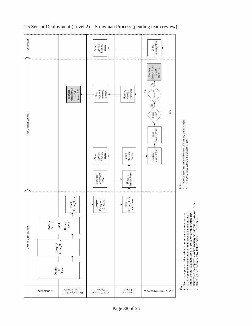
1.5 Sensor Deployment (Level 2) – Strawman Process (pending team review)

Page 39 of 55
1.6 Sensor Performance (Level 2) – Strawman Process (pending team review)

Page 40 of 55
1.6.1 Calibration Management (Level 3) (draft)

Page 41 of 55
1.7.0 Sensor Maintenance (Level 2) (draft)

Page 42 of 55
1.7.1 Create Maintenance Plan (Level 3) (draft)

Page 43 of 55
1.7.2 Maintenance - At Sea (Level 3) (draft)

Page 44 of 55
1.7.3 Evaluate Maintenance Need - Marine Ops (Level 3) (draft)

Page 45 of 55
1.7.4 Maintenance - In Shop – Vendor (Level 3) (draft)

Page 46 of 55
1.7.5 Maintenance - In Shop - Marine Ops (Level 3) (draft)

Page 47 of 55
1.8 Sensor Decommission (Level 2) – Strawman Process (pending team review)

Page 48 of 55
Appendix D: Open Issues Log

Page 49 of 55
Appendix D: Open Issues - Page 2

Page 50 of 55
Appendix D: Open Issues - Page 3

Page 51 of 55
Appendix E: Vendor Maintenance Interview Questionnaire
Vendor Questionnaire Meeting Objective: Review vendor maintenance and process steps for OOI sensors. The purpose is to identify the steps to "interview" a sensor manufacturer for operational maintenance, and to collect supporting documents used to capture the sensor maintenance information. Sensor: ________________________________________ Key Issues: How to disconnect customers from “ownership” of a specific instrument? Is it ok to get back a different instrument from vendor that produces same data (raises issues of defined “standard” data quality ranges). Certain instruments are “tuned” based on deployment conditions. This can mean different hardware is preloaded in the instrument. Should field tests be conducted to validate instrument is within acceptable performance range? Should vendors be providing a data product? Who is responsible for data product quality? Information vendors would like to have from OOI to improve their products. Raw data samples (to be defined); deployment location, deployment time; need to capture more… Interview Questions: What are expected service intervals? Please consider different deployment conditions. What specific service is required at each service interval? What are expected failure points? At what time intervals? What sensor maintenance work must be done at manufacture facility? What work can be done "at sea" with minimal facilities available? What work can be done at OOI Marine Ops Field Services facility? Do you currently provide service contracts? If so, what type of serve work is included? What is the turnaround time for maintenance work? What considerations impact this? What sensor maintenance history tracking do you do? What is the typical frequency of software and/or driver upgrades? What type of service does this require?

Page 52 of 55
Appendix E: Vendor Maintenance Interview Questionnaire – Page 2 What is the typical frequency of hardware upgrades? What type of service does this require? What types of mechanical attach / re-attach to platform issues are there? What are calibration (data certification) snapshots? What is done with the data, if anything? At manufacturer - prior to shipping (compared to standard) On deck calibration - prior to deployment (compared to standard) Co-location calibration - sample taken in close proximity during deployment (in situ, sample,
standard) In Situ calibration - done during operational phase - could be mechanical or data modification) Co-location calibration - sample taken in close proximity at recovery (in situ, sample, standard) Post calibration - internal (e.g. electronic drift) Post calibration - external (e.g. bio-fouling drift) Is there any value in knowing the prior instrument performance characterization if you know the current characterization to a “standard”. What standards are used to determine calibration accuracy? Can you do in situ recalibrations to “on board” standards? Can you do recalibration based on other sensors at the same location? Please describe. What are your general recalibration (data certification) recommendations? What is your “in house” testing process? What testing process do you recommend once the sensor leaves your facility? Does your sensor have ability to respond to "management commands" while in situ? Are your technicians available to provide service at other locations? Do you provide Service FAQ and manuals online? What information would you like OOI to provide to you to improve sensor performance?

Page 53 of 55
Appendix F: Manufacturer Maintenance Use Case
CGSN Process Project - Manufacturer Maintenance Use Case (DRAFT) Functional Roles M Marine Ops (customer) V Vendor V- CS Vendor customer support V- S Vendor shipping & receiving V-M Vendor technical maintenance Start Process M Initiate contact to vendor customer support via (email, web, phone, other ….) preferred? W-CS Respond to M (W prefers direct customer contact – allows for troubleshooting, issue resolution,
collection of valuable service information. Increases customer contact) Data collected: Serial # Service needed / requested
Data provided: RMA # (Return Material Authorization) Shipping instructions
Expected turnaround time (estimated – based on?) Pricing estimate?
M Ship instrument package to vendor (process map will skip shipping steps) V-S Receive, assess, and process instrument package
Data collected: Parts received Serial # s Condition of parts
V-S Notify Marine Ops of instrument package receipt Data provided:
Parts and condition V-S Deliver instrument package to vendor maintenance department (V-M)

Page 54 of 55
Appendix F: Manufacturer Maintenance Use Case – Page 2 V-M Perform technical assessment
Data collected:
Parts received Serial # s Condition of parts Service required Parts required Estimated cost to repair
DECSION: Is estimated cost to repair within “service contract”? Question includes turnaround time. IF YES: V-M Perform instrument package repair IF NO:
V-M Notify Marine Ops of instrument package repair cost, request approval to proceed Data provided:
Service required Parts required Estimated cost to repair Estimated time to repair
M Responds with decision
DECSION: Does M approve repair cost and/or turn around time? IF YES: V-M Perform instrument package repair IF NO:
V-M Returns “old” instrument package and provides “new” replacement instrument package
V-M Perform instrument package testing (process assumes loop back to repair step if failure)
Data collected: Original performance characterization (calibration data)
Current performance characterization (calibration data) Estimated remaining “life” of instrument package Service history Julie can you provide a few “calibration sheet” examples
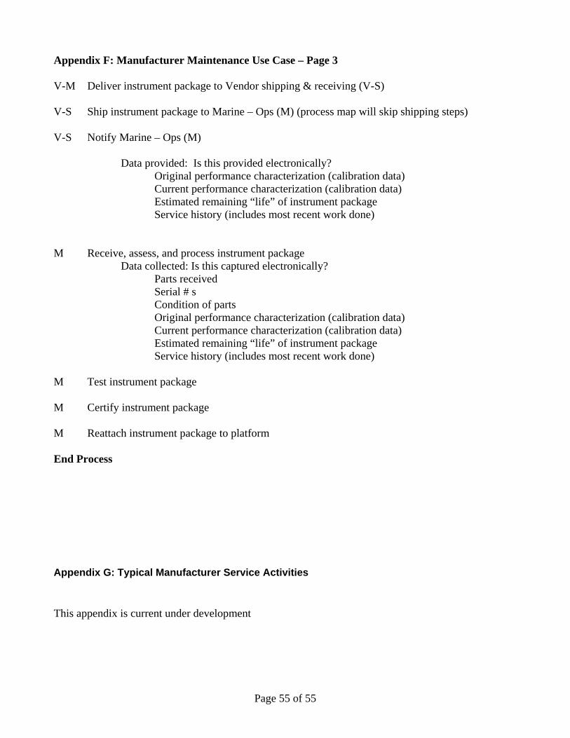
Page 55 of 55
Appendix F: Manufacturer Maintenance Use Case – Page 3 V-M Deliver instrument package to Vendor shipping & receiving (V-S) V-S Ship instrument package to Marine – Ops (M) (process map will skip shipping steps) V-S Notify Marine – Ops (M)
Data provided: Is this provided electronically? Original performance characterization (calibration data)
Current performance characterization (calibration data) Estimated remaining “life” of instrument package Service history (includes most recent work done)
M Receive, assess, and process instrument package
Data collected: Is this captured electronically? Parts received Serial # s Condition of parts
Original performance characterization (calibration data) Current performance characterization (calibration data) Estimated remaining “life” of instrument package Service history (includes most recent work done)
M Test instrument package M Certify instrument package M Reattach instrument package to platform End Process
Appendix G: Typical Manufacturer Service Activities This appendix is current under development