Embed Size (px)
Citation preview
UNIT-1
Introduction to Object Oriented Analysis and Design
WHAT IS OBJECT?
• An "object" is anything to which a concept applies, in our awareness.
• Things drawn from the problem domain or solution space.
E.g., a living person in the problem domain, a software component in the solution
space
WHAT IS OBJECT-ORIENTATION?
� If any application was developed based on the following concepts then that
application will comes under object orientation:
o Class and Object
o Message
o Operation and Method
o Encapsulation
o Abstraction
o Inheritance
o Polymorphism
Class and Object in UML
UML class is a classifier which describes a set of objects that share the same
� features,
� constraints,
� semantics (meaning).
An object is an individual [thing] with a state and relationships to other objects. The state
of an object identifies the values for that object of properties of the classifier of the object.
Message in UML
A message defines a specific kind of communication between lifelines of an interaction. A
communication can be, for example, invoking an operation, replying back, creating or
destroying an instance, raising a signal. It also specifies the sender and the receiver of the
message.
Operation and Method in UML
An operation has a signature, which may restrict the actual parameters that are possible.
Method is defined as the implementation of an operation. It specifies the algorithm or
procedure associated with an operation.
Encapsulation in UML
Object is defined as an entity with a well-defined boundary and identity that encapsulates
state (attributes and relationships) and behavior (operations, methods, and state
machines).
Abstraction in UML
Abstraction in UML corresponds to the concept of abstraction in OOD. UML provides
different types (subclasses) of abstraction, including realizations (i.e. implementations).
Abstraction is a dependency relationship that relates two elements or sets of elements
(called client and supplier) representing the same concept but at different levels of
abstraction or from different viewpoints.
Inheritance in UML
Inheritance supplements generalization relationship.
Generalization is defined as a taxonomic relationship between a more general element and
a more specific element. The more specific element is fully consistent with the more
general element and contains some additional information. An instance of the more specific
element may be used where the more general element is allowed.
Polymorphism in UML
There is no definition of polymorphism in UML specifications but there are some
differences in how this term is used in different versions of UML.
o In UML 1.4.2 operation declares whether or not it may be realized by a different
method in a subclass. Methods realizing polymorphic operation have the same
signature as the operation and have a body implementing the specification of the
operation. Methods in descendants override and replace methods inherited from
ancestors.
o The UML 2.4.1 specification had one obscure statement mentioning polymorphism
that is Operations are specified in the model and can be dynamically selected only
through polymorphism.
WHY OBJECT ORIENTATION:
Reduced Maintenance: The primary goal of object-oriented development is the assurance
that the system will enjoy a longer life while having far smaller maintenance costs. Because
most of the processes within the system are encapsulated, the behaviors may be reused
and incorporated into new behaviors.
Real-World Modeling: Object-oriented system tend to model the real world in a more
complete fashion than do traditional methods. Objects are organized into classes of
objects, and objects are associated with behaviors. The model is based on objects, rather
than on data and processing.
Improved Reliability and Flexibility: Object-oriented system promise to be far more
reliable than traditional systems, primarily because new behaviors can be "built" from
existing objects.
High Code Reusability: When a new object is created, it will automatically inherit the data
attributes and characteristics of the class from which it was spawned.
WHAT IS OOAD?
Analysis: Emphasizes an investigation of the problem and requirements rather than a
solution. (Understanding, finding and describing concepts in the problem domain.)
Design: Emphasizes a conceptual solution that fulfills the requirements rather than it’s
implementation.(Understanding and defining software solution/objects that represent the
analysis concepts and will eventually be implemented in code.)
OOAD:Analysis is object-oriented and design is object-oriented. A software development
approach that emphasizes a logical solution based on objects.
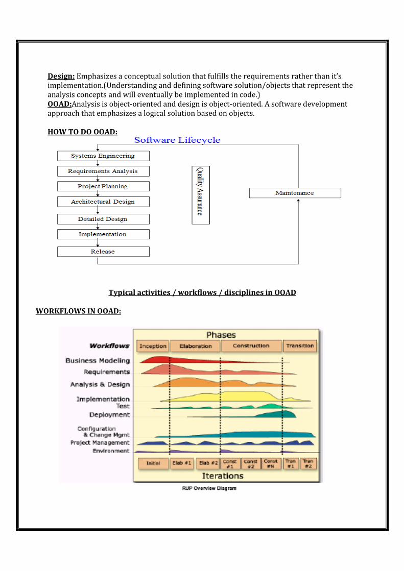
HOW TO DO OOAD:
Typical activities / workflows / disciplines in OOAD
WORKFLOWS IN OOAD:
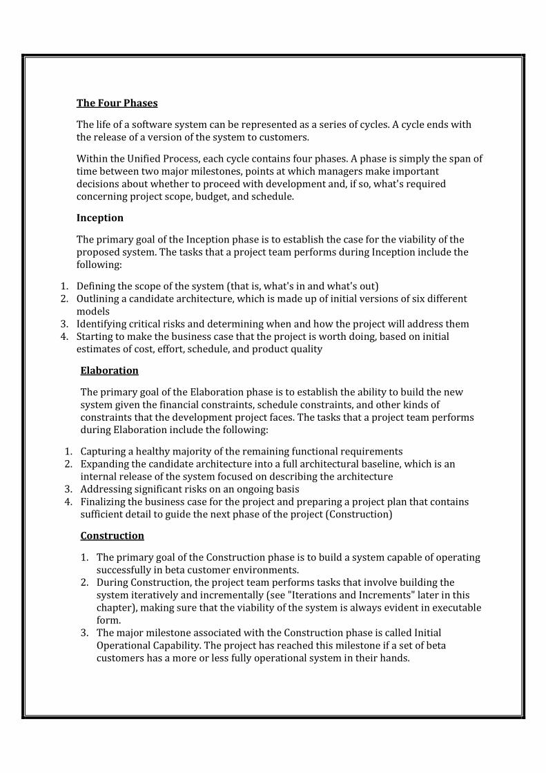
The Four Phases
The life of a software system can be represented as a series of cycles. A cycle ends with
the release of a version of the system to customers.
Within the Unified Process, each cycle contains four phases. A phase is simply the span of
time between two major milestones, points at which managers make important
decisions about whether to proceed with development and, if so, what's required
concerning project scope, budget, and schedule.
Inception
The primary goal of the Inception phase is to establish the case for the viability of the
proposed system. The tasks that a project team performs during Inception include the
following:
1. Defining the scope of the system (that is, what's in and what's out)
2. Outlining a candidate architecture, which is made up of initial versions of six different
models
3. Identifying critical risks and determining when and how the project will address them
4. Starting to make the business case that the project is worth doing, based on initial
estimates of cost, effort, schedule, and product quality
Elaboration
The primary goal of the Elaboration phase is to establish the ability to build the new
system given the financial constraints, schedule constraints, and other kinds of
constraints that the development project faces. The tasks that a project team performs
during Elaboration include the following:
1. Capturing a healthy majority of the remaining functional requirements
2. Expanding the candidate architecture into a full architectural baseline, which is an
internal release of the system focused on describing the architecture
3. Addressing significant risks on an ongoing basis
4. Finalizing the business case for the project and preparing a project plan that contains
sufficient detail to guide the next phase of the project (Construction)
Construction
1. The primary goal of the Construction phase is to build a system capable of operating
successfully in beta customer environments.
2. During Construction, the project team performs tasks that involve building the
system iteratively and incrementally (see "Iterations and Increments" later in this
chapter), making sure that the viability of the system is always evident in executable
form.
3. The major milestone associated with the Construction phase is called Initial
Operational Capability. The project has reached this milestone if a set of beta
customers has a more or less fully operational system in their hands.
Transition
1. The primary goal of the Transition phase is to roll out the fully functional system to
customers.
2. During Transition, the project team focuses on correcting defects and modifying the
system to correct previously unidentified problems.
3. The major milestone associated with the Transition phase is called Product Release.
The Workflows
Within the Unified Process, five workflows cut across the set of four phases: Requirements,
Analysis, Design, Implementation, and Test. Each workflow is a set of activities that various
project workers perform.
Business Modeling: The purpose of the Business Modeling discipline is to:
_ Understand the structure and the dynamics of the organization in which a system is to be
deployed (the target organization)
_ Understand current problems in the target organization and identify improvement
potential
_ Ensure that customers, end users, and developers have a common understanding of the
target organization
_ Derive the system requirements needed to support the target organization
Requirements: The purpose of the Requirements discipline is to:
_ Establish and maintain agreement with the customers and other stakeholders on what the
system should do
_ Provide system developers with a better understanding of the system requirements
_ Define the boundaries of (delimit) the system
_ Provide a basis for planning the technical contents of iterations
_ Provide a basis for estimating the cost and time to develop the system
Analysis and Design: The purpose of the Analysis and Design discipline is to:
_ Transform the requirements into a design of the system-to-be
_ Evolve a robust architecture for the system
_ Adapt the design to match the implementation environment
Implementation: The purpose of the Implementation discipline is to:
_ Define the organization of the implementation
_ Implement the design elements
_ Unit test the implementation
_ Integrate the results produced by individual implementers (or teams), resulting in
an executable system
Test: The purpose of the Test discipline is to:
_ Find and document defects in software quality
_ Provide general advice about perceived software quality
_ Prove the validity of the assumptions made in design and requirement
specifications through concrete demonstration
_ Validate that the software product functions as designed
_ Validate that the software product functions as required (that is, the requirements
have been implemented appropriately)
Deployment: The purpose of the Deployment discipline is to:
_ Ensure that the software product is available for its end users
Configuration and Change Management: The purpose of the Configuration and Change
Management discipline is to:
_ Identify configuration items5
_ Restrict changes to those items
_ Audit changes made to those items
_ Define and manage configurations6 of those items
Project Management: The purpose of the Project Management discipline is to:
_ Manage a software-intensive project
_ Plan, staff, execute, and monitor a project
_ Manage risk
Environment: The purpose of the Environment discipline is to:
_ Provide the software development organization with the software development
environment—both processes and tools—that will support the development team.
This includes configuring the process for a particular project, as well as developing
guidelines in support of the project.
Introduction to iterative development and the Unified Process
Unified Process:The Rational Unified Process is a software development process
framework that provides a disciplined approach to assigning tasks and responsibilities
within a development organization. Its goal is to ensure the production of high quality
software that meets the needs of its end users within a predictable schedule and budget
(“better software faster”).
RUP was explicitly designed to support the implementation of six best practices.
■Develop iteratively. Deliver the functionality of the system in a successive series of
releases of increasing completeness, where each release is the result of an iteration. The
selection of which requirements are addressed within each iteration is driven by the
mitigation of project risks, with the most critical risks being addressed first.
■Manage requirements. Use a systematic approach to elicit and document the system
requirements, and then manage changes to those requirements, including assessing the
impact of those changes on the rest of the system. Effective requirements management
involves maintaining a clear statement of the requirements, as well as maintaining
traceability from these requirements to the other project artifacts.
■Use component architectures. Structure the software architecture using components2.
A component-based development approach to architecture tends to reduce the complexity
of the solution, and results in an architecture that is more robust and resilient, and which
enables more effective reuse.
■Model visually. Produce a set of visual models of the system, each of which emphasizes
specific details, and “ignores”(abstracts, filters away) others. These models promote a
better understanding of the system being developed and provide a mechanism for
unambiguous communication among team members (“a picture is worth a thousand
words”).
■Continuously verify quality. Continuously assess the quality of the system with respect
to its functional and nonfunctional requirements. Perform testing as part of every iteration.
It is a lot less expensive to correct defects found early in the software development life
cycle than it is to fix defects found later.
■Manage change. Establish a disciplined and controlled approach for managing change
(changing requirements, technology, resources, products, platforms, and so on).
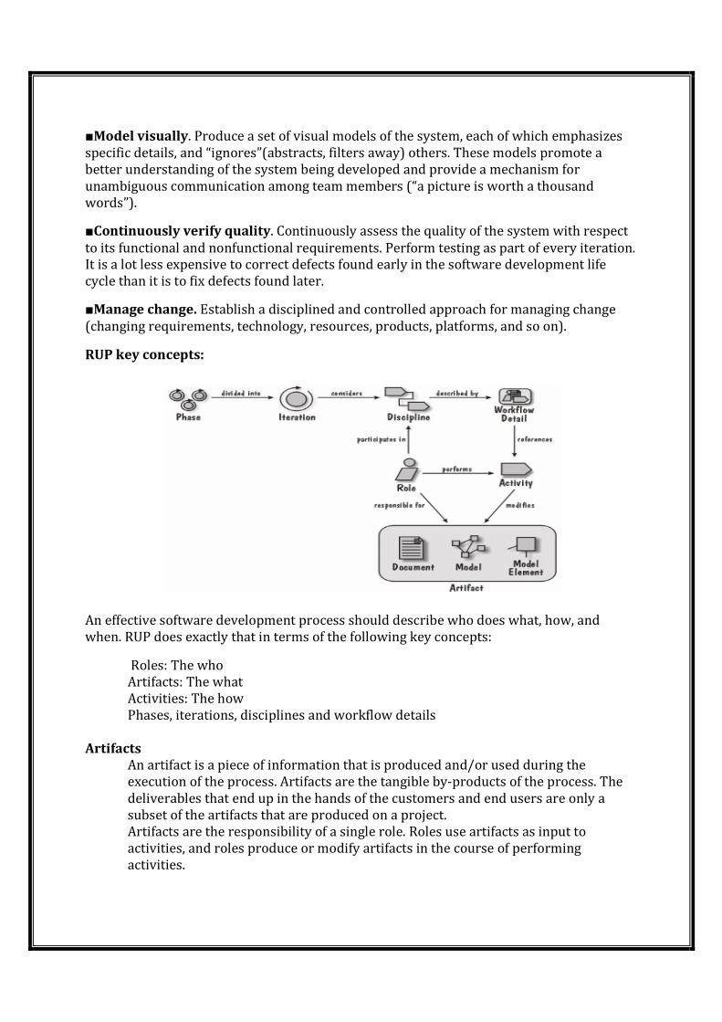
RUP key concepts:
An effective software development process should describe who does what, how, and
when. RUP does exactly that in terms of the following key concepts:
Roles: The who
Artifacts: The what
Activities: The how
Phases, iterations, disciplines and workflow details
Artifacts
An artifact is a piece of information that is produced and/or used during the
execution of the process. Artifacts are the tangible by-products of the process. The
deliverables that end up in the hands of the customers and end users are only a
subset of the artifacts that are produced on a project.
Artifacts are the responsibility of a single role. Roles use artifacts as input to
activities, and roles produce or modify artifacts in the course of performing
activities.
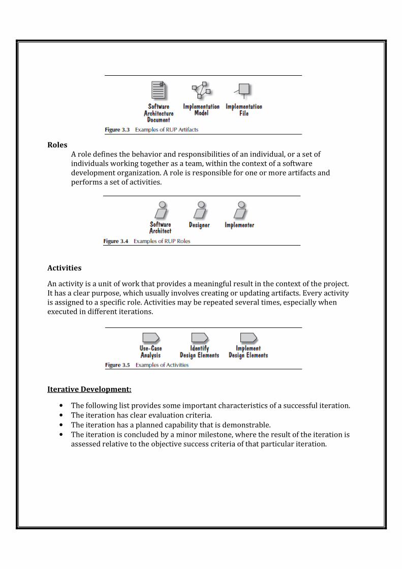
Roles
A role defines the behavior and responsibilities of an individual, or a set of
individuals working together as a team, within the context of a software
development organization. A role is responsible for one or more artifacts and
performs a set of activities.
Activities
An activity is a unit of work that provides a meaningful result in the context of the project.
It has a clear purpose, which usually involves creating or updating artifacts. Every activity
is assigned to a specific role. Activities may be repeated several times, especially when
executed in different iterations.
Iterative Development:
• The following list provides some important characteristics of a successful iteration.
• The iteration has clear evaluation criteria.
• The iteration has a planned capability that is demonstrable.
• The iteration is concluded by a minor milestone, where the result of the iteration is
assessed relative to the objective success criteria of that particular iteration.
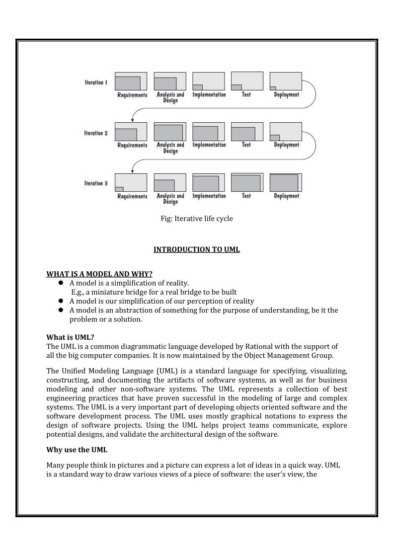
Fig: Iterative life cycle
INTRODUCTION TO UML
WHAT IS A MODEL AND WHY?
� A model is a simplification of reality.
E.g., a miniature bridge for a real bridge to be built
� A model is our simplification of our perception of reality
� A model is an abstraction of something for the purpose of understanding, be it the
problem or a solution.
What is UML?
The UML is a common diagrammatic language developed by Rational with the support of
all the big computer companies. It is now maintained by the Object Management Group.
The Unified Modeling Language (UML) is a standard language for specifying, visualizing,
constructing, and documenting the artifacts of software systems, as well as for business
modeling and other non-software systems. The UML represents a collection of best
engineering practices that have proven successful in the modeling of large and complex
systems. The UML is a very important part of developing objects oriented software and the
software development process. The UML uses mostly graphical notations to express the
design of software projects. Using the UML helps project teams communicate, explore
potential designs, and validate the architectural design of the software.
Why use the UML
Many people think in pictures and a picture can express a lot of ideas in a quick way. UML
is a standard way to draw various views of a piece of software: the user's view, the
architecture, the internal structure of the software, the source code, and the hardware
involved.
Goals of UML :
1. Provide users with a ready-to-use, expressive visual modeling language so they can
develop and exchange meaningful models.
2. Provide extensibility and specialization mechanisms to extend the core concepts.
3. Be independent of particular programming languages and development processes.
4. Provide a formal basis for understanding the modeling language.
5. Encourage the growth of the OO tools market.
6. Support higher-level development concepts such as collaborations, frameworks, patterns
and components.
7. Integrate best practices.
Benefits of UML:
1. Your software system is professionally designed and documented before it is coded. You
will know exactly what you are getting, in advance.
2. Since system design comes first, reusable code is easily spotted and coded with the
highest efficiency. You will have lower development costs.
3. Logic 'holes' can be spotted in the design drawings. Your software will behave as you
expect it to. There are fewer surprises.
4. The overall system design will dictate the way the software is developed. The right
decisions are made before you are married to poorly written code. Again, your overall costs
will be less.
5. UML lets us see the big picture. We can develop more memory and processor efficient
systems.
6. When we come back to make modifications to your system, it is much easier to work on a
system that has UML documentation. Much less 'relearning' takes place. Your system
maintenance costs will be lower.
7. If you should find the need to work with another developer, the UML diagrams will allow
them to get up to speed quickly in your custom system. Think of it as a schematic to a radio.
How could a tech fix it without it?
8. If we need to communicate with outside contractors or even your own programmers, it is
much more efficient.
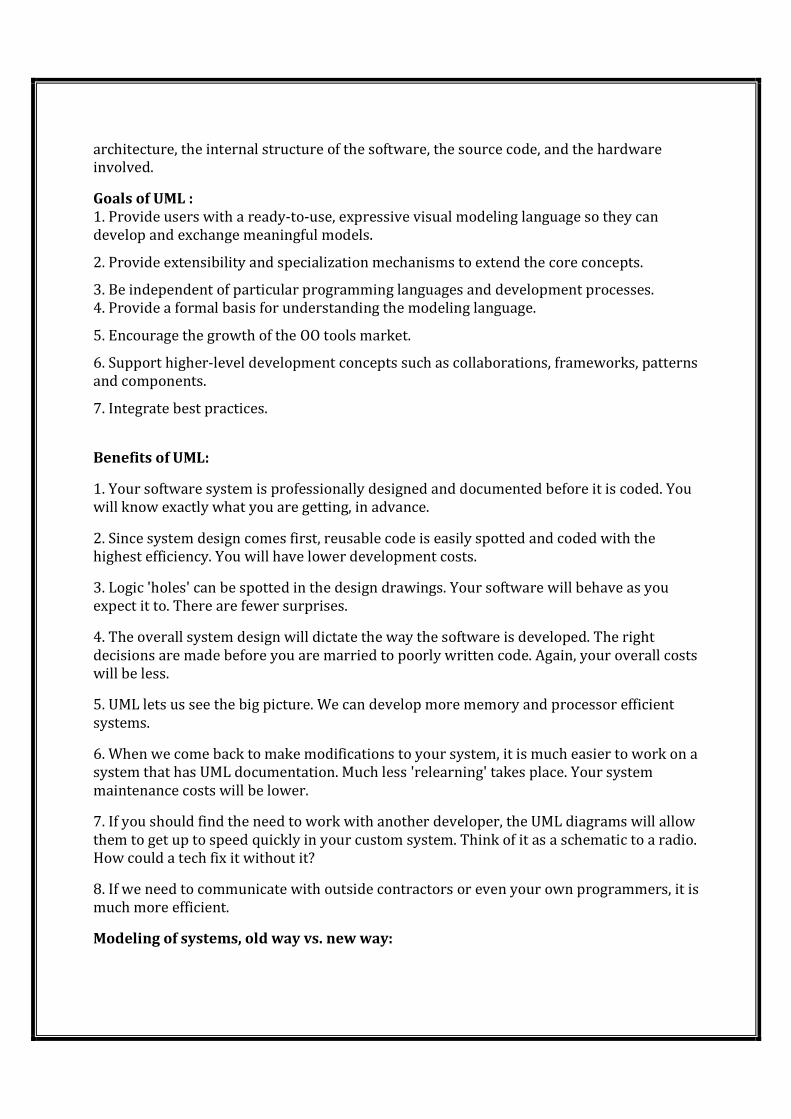
Modeling of systems, old way vs. new way:
System is a combination of software and hardware that provides a solution for a business
problem.
Process of developing that system involves a lot of people. First of all is the client, the
person who has the problem to be solved. An analyst documents the client's problem and
relays it to developers, programmers who build the software that solves the problem, test it
and deploy it on computer hardware.
The waterfall method for modeling of systems
� The old way of system modeling, known as the waterfall method, specifies that
analysis, design, coding and deployment follow one another. Only when one is
complete can the next one begin. If an analyst hands off analysis to a designer, who
hands off a design to a developer, chances are that the three team members will
rarely work together and share important insights. Usually the adherents of the
waterfall method give coding a big amount of project time; it takes a valuable time
away from analysis and design.
� In the new way, contemporary software engineering stress continuing interplay
among the stages of development. Analysts and designers, for example, go back and
forth to evolve a solid foundation for the programmers. Programmers, in turn,
interact with analysts and designers to share their insights, modify designs, and
strengthen their code. The advantage is that as understanding grows, the team
incorporates new ideas and builds a stronger system.
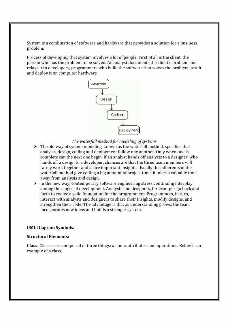
UML Diagram Symbols:
Structural Elements:
Class: Classes are composed of three things: a name, attributes, and operations. Below is an
example of a class.
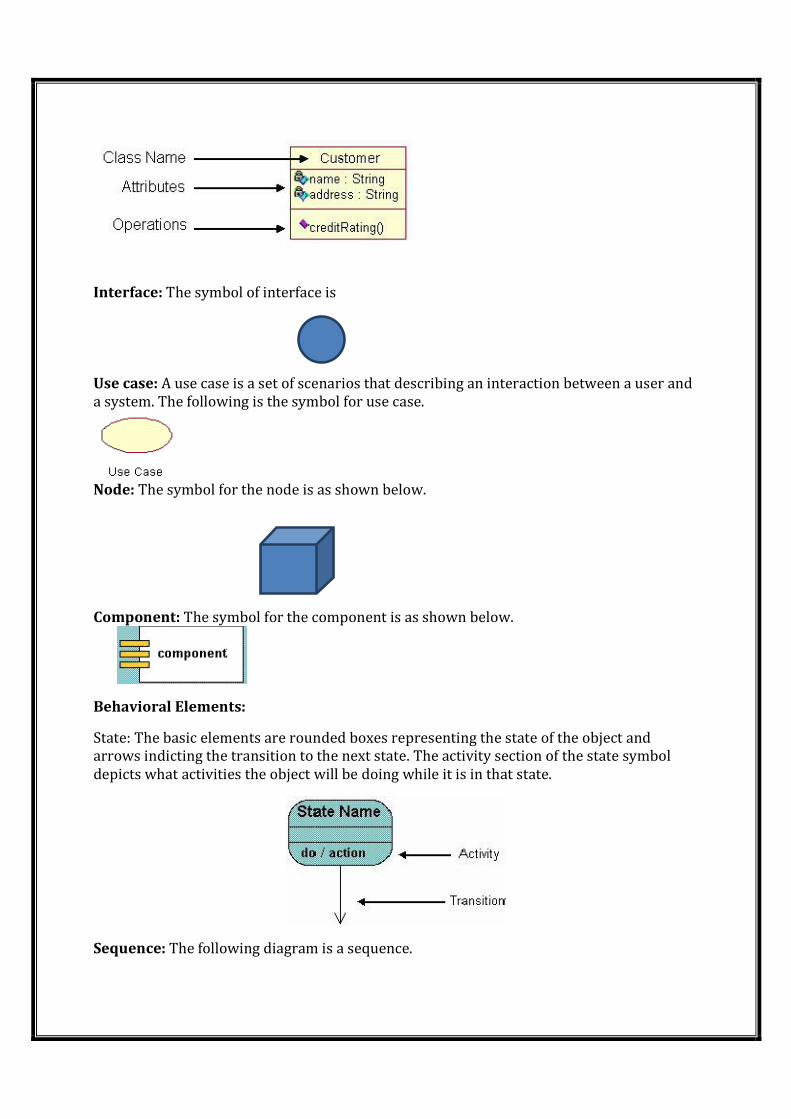
Interface: The symbol of interface is
Use case: A use case is a set of scenarios that describing an interaction between a user and
a system. The following is the symbol for use case.
Node: The symbol for the node is as shown below.
Component: The symbol for the component is as shown below.
Behavioral Elements:
State: The basic elements are rounded boxes representing the state of the object and
arrows indicting the transition to the next state. The activity section of the state symbol
depicts what activities the object will be doing while it is in that state.
Sequence: The following diagram is a sequence.
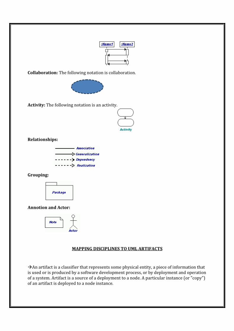
Collaboration: The following notation is collaboration.
Activity: The following notation is an activity.
Relationships:
Grouping:
Annotion and Actor:
MAPPING DISCIPLINES TO UML ARTIFACTS
�An artifact is a classifier that represents some physical entity, a piece of information that
is used or is produced by a software development process, or by deployment and operation
of a system. Artifact is a source of a deployment to a node. A particular instance (or "copy")
of an artifact is deployed to a node instance.
�Some real life examples of UML artifacts are:
� text document
� source file
� script
� binary executable file
� archive file
� database table
Introduction to Design Patterns
• A pattern is a recurring solution to a standard problem
• A pattern describes a problem which occurs over and over again in our
environment, and then describes the core of the solution to that problem, in such a
way that you can use this solution a million times over, without ever doing it the
same way twice.
Patterns in engineering
• Mature engineering disciplines have handbooks
describing successful solutions to known problems
• Automobile designers don't design cars from scratch
using the laws of physics
• Instead, they reuse standard designs with successful
track records, learning from experience
� Design patterns have 4 essential elements:
o Pattern name: increases vocabulary of designers
o Problem: intent, context, when to apply
o Solution: UML-like structure, abstract code
o Consequences: results and tradeoffs
Types of Patterns
Creational patterns:
• Deal with initializing and configuring classes and objects
• Creational patterns are associated with control mechanisms of creating objects. The
basic mode of forming an object may be problematic in some projects and may lead
to unnecessary complexity in some areas. Creational patterns are supposed to
prevent from occurring problems and introduce more control over creating objects.
Their task is to separate the processes of creation, completion and representation of
an object.
• There are five well-known design patterns possible to implement in a wide scope of
programming languages:
� Abstract Factory Pattern
� Builder Pattern
� Factory Method Pattern
� Prototype Pattern
� Singleton Pattern
Structural patterns:
o Deal with decoupling interface and implementation of classes and objects
o Composition of classes or objects
Behavioral patterns:
o Deal with dynamic interactions among societies of classes and objects
o How they distribute responsibility
Benefits of Design Patterns
� Design patterns enable large-scale reuse of software architectures and also help
document systems
� Patterns explicitly capture expert knowledge and design tradeoffs and make it more
widely available
� Patterns help improve developer communication
� Pattern names form a common vocabulary
Goals of design patterns:
1. Help designer focus on solution.
2. Provide a common language for design discussion.
3. Provide solution to real-world problem.
4. Document decision that lead to the solution.
5. Reuse is very useful.
6. Quick to solve problem and development process.
Good design leads to software that is:
1. Correct – does what it should
2. Robust – tolerant of misuse, e.g. faulty data
3. Flexible – adaptable to shifting requirements
4. Reusable – cut production costs for code
5. Efficient – good use of processor and memory
MVC Architecture
Model: The model represents data and the rules that govern access to and updates of
this data. In enterprise software, a model often serves as a software approximation of a
real-world process.
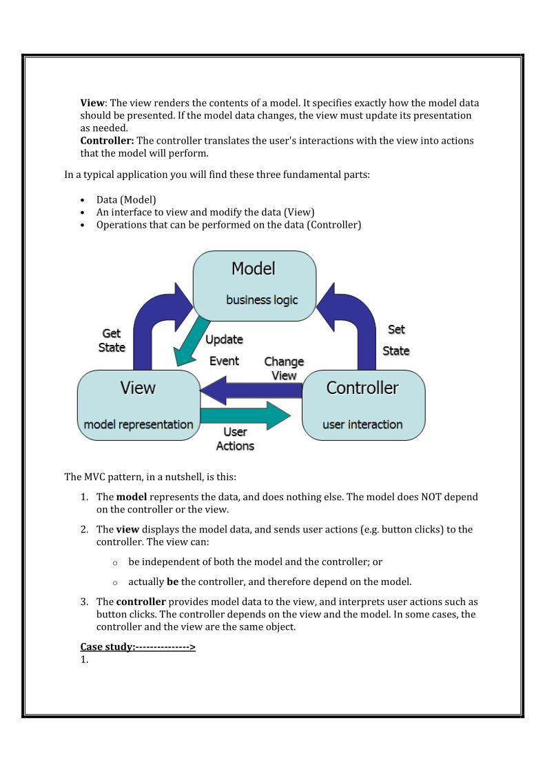
View: The view renders the contents of a model. It specifies exactly how the model data
should be presented. If the model data changes, the view must update its presentation
as needed.
Controller: The controller translates the user's interactions with the view into actions
that the model will perform.
In a typical application you will find these three fundamental parts:
• Data (Model)
• An interface to view and modify the data (View)
• Operations that can be performed on the data (Controller)
The MVC pattern, in a nutshell, is this:
1. The model represents the data, and does nothing else. The model does NOT depend
on the controller or the view.
2. The view displays the model data, and sends user actions (e.g. button clicks) to the
controller. The view can:
o be independent of both the model and the controller; or
o actually be the controller, and therefore depend on the model.
3. The controller provides model data to the view, and interprets user actions such as
button clicks. The controller depends on the view and the model. In some cases, the
controller and the view are the same object.
Case study:--------------->
1.
UNIT-2
INCEPTION;
The aim of the inception phase is to determine whether the proposed software product
is economically viable(Capable of living-anukulamina)
� Inception phase of the UP has (5) objectives
� Identify the business need for the project
� Establish the vision for the solution
� Identify scope of the new system and the project
� Develop preliminary schedules and cost estimates
� Develop the business case for the project
� Inception phase may be completed in one iteration
Artifacts:
� Vision
� Use Case Model
� Supplementary Specification
� Glossary
� Risk Plan
� Prototypes
� Iteration Plan
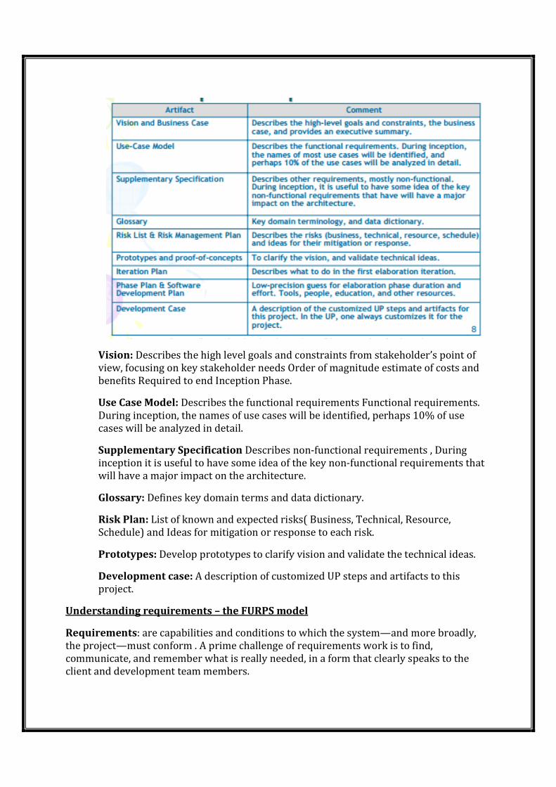
Vision: Describes the high level goals and constraints from stakeholder’s point of
view, focusing on key stakeholder needs Order of magnitude estimate of costs and
benefits Required to end Inception Phase.
Use Case Model: Describes the functional requirements Functional requirements.
During inception, the names of use cases will be identified, perhaps 10% of use
cases will be analyzed in detail.
Supplementary Specification Describes non-functional requirements , During
inception it is useful to have some idea of the key non-functional requirements that
will have a major impact on the architecture.
Glossary: Defines key domain terms and data dictionary.
Risk Plan: List of known and expected risks( Business, Technical, Resource,
Schedule) and Ideas for mitigation or response to each risk.
Prototypes: Develop prototypes to clarify vision and validate the technical ideas.
Development case: A description of customized UP steps and artifacts to this
project.
Understanding requirements – the FURPS model
Requirements: are capabilities and conditions to which the system—and more broadly,
the project—must conform . A prime challenge of requirements work is to find,
communicate, and remember what is really needed, in a form that clearly speaks to the
client and development team members.
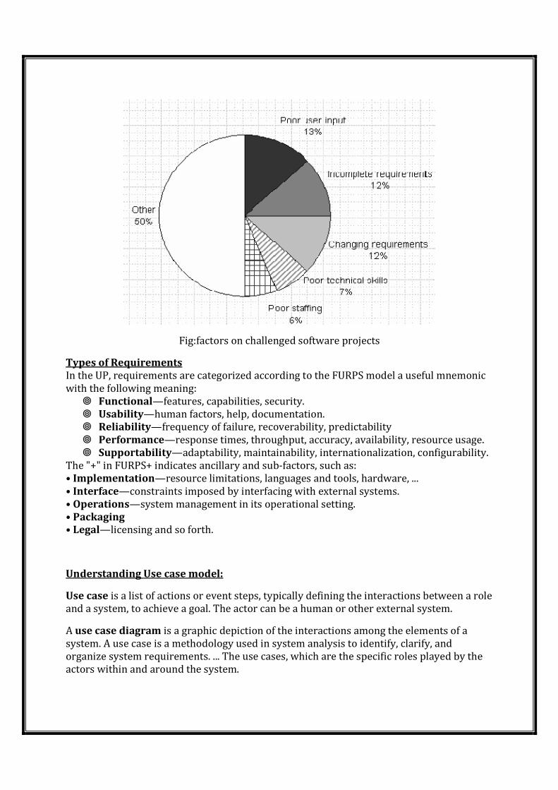
Fig:factors on challenged software projects
Types of Requirements
In the UP, requirements are categorized according to the FURPS model a useful mnemonic
with the following meaning:
� Functional—features, capabilities, security.
� Usability—human factors, help, documentation.
� Reliability—frequency of failure, recoverability, predictability
� Performance—response times, throughput, accuracy, availability, resource usage.
� Supportability—adaptability, maintainability, internationalization, configurability.
The "+" in FURPS+ indicates ancillary and sub-factors, such as:
• Implementation—resource limitations, languages and tools, hardware, ...
• Interface—constraints imposed by interfacing with external systems.
• Operations—system management in its operational setting.
• Packaging
• Legal—licensing and so forth.
Understanding Use case model:
Use case is a list of actions or event steps, typically defining the interactions between a role
and a system, to achieve a goal. The actor can be a human or other external system.
A use case diagram is a graphic depiction of the interactions among the elements of a
system. A use case is a methodology used in system analysis to identify, clarify, and
organize system requirements. ... The use cases, which are the specific roles played by the
actors within and around the system.
How do we identify the usecases:
To identify use cases we will take the following steps:
Step 1: Identify candidate system actors.
Step 2: Identify the goals of the actors.
Step 3: Identify the candidate use cases.
Step 4: Identify the start point for each use case.
Step 5: Identify the end point for each use case.
Use case description: A use case is a written description of how users will perform tasks on
your website. It outlines, from a user's point of view, a system's behavior as it responds to a
request.
Types of Use Cases:
There are three types of use cases: Essential, Concrete and Abstract.
Essential Use Cases ... are expressed in an ideal form that remains relatively free of
technology and implementation details; design decisions are deferred and abstracted,
especially those related to the user interface.
Concrete or Real Use Case concretely describes the process in terms of its real current
design, committed to specific input and output technologies and so on. When a user
interface is involved, they often show screen shots and discuss interaction with the
widgets.
Abstract Use Case is not complete and has no actor that initiates it but is used by another
use cases.
Case Study - Answering System:
The Answering System is system foe answering phone calls and recording messages from
callers. It is intended as a personal answering system for a single owner. It will support:
Modes for announce only and accepting caller messages
• Ability to review caller messages
• Personalized greetings
• Local management of modes, greetings, and caller messages
Answering System Domain Use Case Model
Let us analyze the requirement document to identify the potential actors and use cases of
the system. First, let's list the potential actors. A quick look at requirement document
shows the following terms and entities specific to the system:
The caller is the person who is answered and their messages are taken
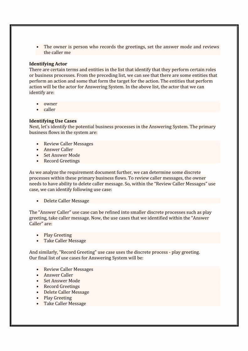
• The owner is person who records the greetings, set the answer mode and reviews
the caller me
Identifying Actor
There are certain terms and entities in the list that identify that they perform certain roles
or business processes. From the preceding list, we can see that there are some entities that
perform an action and some that form the target for the action. The entities that perform
action will be the actor for Answering System. In the above list, the actor that we can
identify are:
• owner
• caller
Identifying Use Cases
Next, let's identify the potential business processes in the Answering System. The primary
business flows in the system are:
• Review Caller Messages
• Answer Caller
• Set Answer Mode
• Record Greetings
As we analyze the requirement document further, we can determine some discrete
processes within these primary business flows. To review caller messages, the owner
needs to have ability to delete caller message. So, within the “Review Caller Messages” use
case, we can identify following use case:
• Delete Caller Message
The “Answer Caller” use case can be refined into smaller discrete processes such as play
greeting, take caller message. Now, the use cases that we identified within the “Answer
Caller” are:
• Play Greeting
• Take Caller Message
And similarly, “Record Greeting” use case uses the discrete process - play greeting.
Our final list of use cases for Answering System will be:
• Review Caller Messages
• Answer Caller
• Set Answer Mode
• Record Greetings
• Delete Caller Message
• Play Greeting
• Take Caller Message
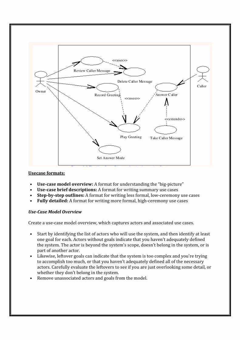
Usecase formats:
• Use-case model overview: A format for understanding the “big-picture”
• Use-case brief descriptions: A format for writing summary use cases
• Step-by-step outlines: A format for writing less formal, low-ceremony use cases
• Fully detailed: A format for writing more formal, high-ceremony use cases
Use-Case Model Overview
Create a use-case model overview, which captures actors and associated use cases.
• Start by identifying the list of actors who will use the system, and then identify at least
one goal for each. Actors without goals indicate that you haven’t adequately defined
the system. The actor is beyond the system’s scope, doesn’t belong in the system, or is
part of another actor.
• Likewise, leftover goals can indicate that the system is too complex and you're trying
to accomplish too much, or that you haven’t adequately defined all of the necessary
actors. Carefully evaluate the leftovers to see if you are just overlooking some detail, or
whether they don’t belong in the system.
• Remove unassociated actors and goals from the model.
Sometimes, this overview may provide enough information to serve as the use-case model
for very small, high-communicating, low-ceremony project teams. Usually, the use-case
model overview is the first step of identifying use cases and system boundaries.
Use-Case brief descriptions
Write two to four sentences per use case, capturing key activities and key-extension
handling.
• Expand the high priority use-cases by writing a two- to four-sentence use cases for
each entry in the list.
• Briefly describe each use case’s main scenario and most important extensions.
• Include enough information to eliminate ambiguity for at least the main scenario.
Step-by-step outlines
Write the step-by-step outline which describes the interaction between the actor(s) and
the system.
• Key scenarios are detailed to describe the interaction
• Triggering events are specified
• Information exchanged is described
Fully Detailed
Complete all sections of the Use-Case Specification template.
• The main scenario is detailed
• All alternative flows are identified and detailed
• Special requirements are complete and un-ambiguous
• Pre- and Post-conditions are specified.
Goals and scope of a use case:
1. Provide users with a ready-to-use, expressive visual modeling language to develop and
exchange meaningful models.
2. Furnish extensibility and specialization mechanisms to extend the core concepts.
3. Support specifications that are independent of particular programming languages and
development processes.
4. Provide a formal basis for understanding the modeling language.
5. Encourage the growth of the object tools market.
6. Support higher-level development concepts such as components, collaborations,
frameworks and patterns.
7. Integrate best practices.
�The design scope is not a specific property of a use case but something you should
consider carefully to make sure you understand what is inside and what is outside the
boundary of the use case.
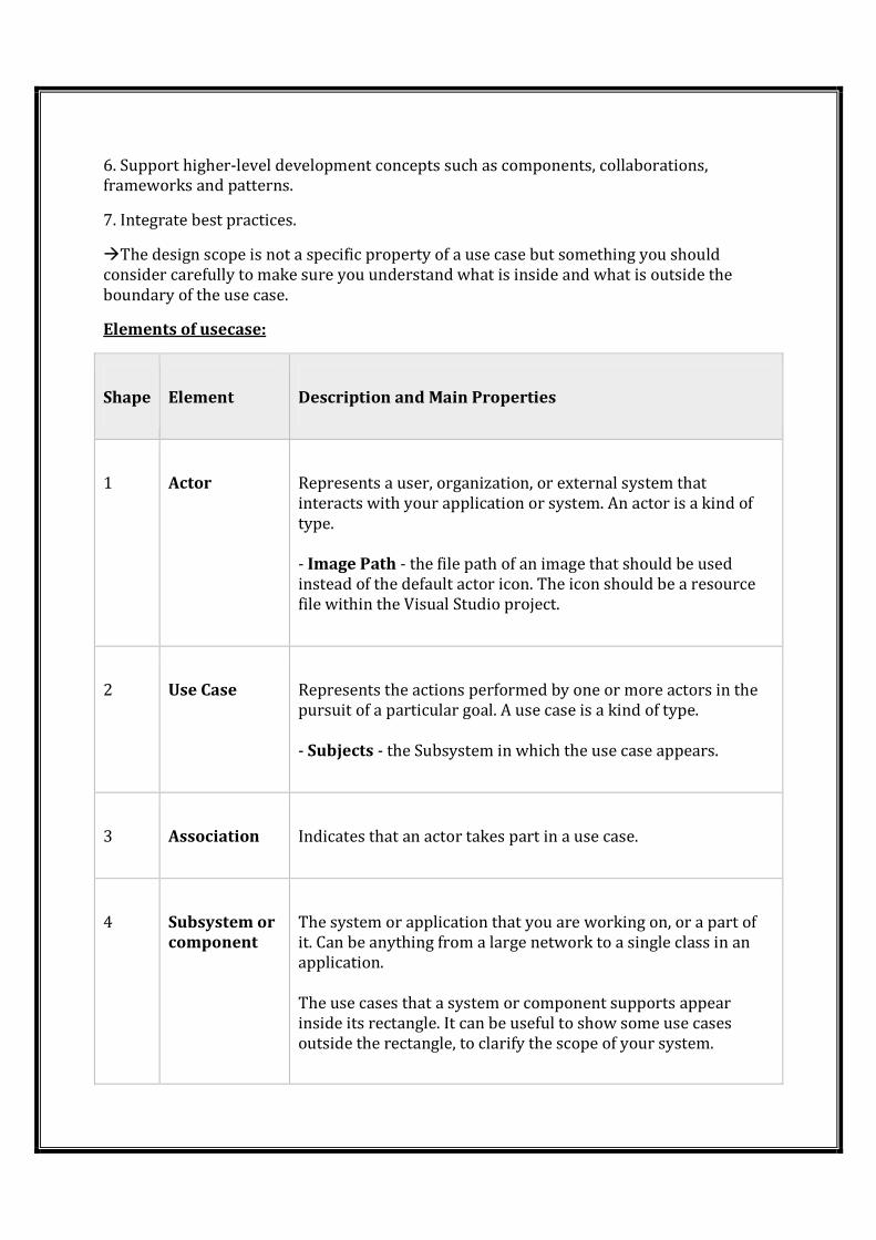
Elements of usecase:
Shape Element Description and Main Properties
1 Actor Represents a user, organization, or external system that
interacts with your application or system. An actor is a kind of
type.
- Image Path - the file path of an image that should be used
instead of the default actor icon. The icon should be a resource
file within the Visual Studio project.
2 Use Case Represents the actions performed by one or more actors in the
pursuit of a particular goal. A use case is a kind of type.
- Subjects - the Subsystem in which the use case appears.
3 Association Indicates that an actor takes part in a use case.
4 Subsystem or
component
The system or application that you are working on, or a part of
it. Can be anything from a large network to a single class in an
application.
The use cases that a system or component supports appear
inside its rectangle. It can be useful to show some use cases
outside the rectangle, to clarify the scope of your system.
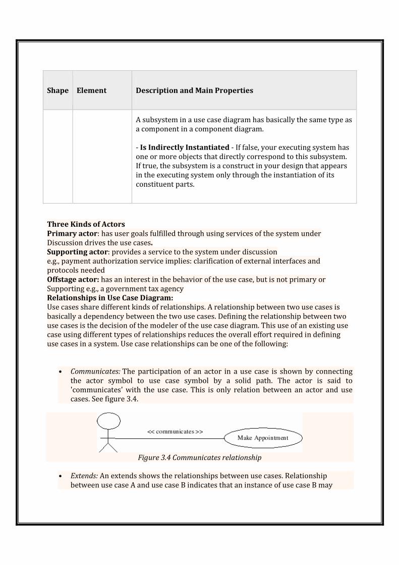
Shape Element Description and Main Properties
A subsystem in a use case diagram has basically the same type as
a component in a component diagram.
- Is Indirectly Instantiated - If false, your executing system has
one or more objects that directly correspond to this subsystem.
If true, the subsystem is a construct in your design that appears
in the executing system only through the instantiation of its
constituent parts.
Three Kinds of Actors
Primary actor: has user goals fulfilled through using services of the system under
Discussion drives the use cases.
Supporting actor: provides a service to the system under discussion
e.g., payment authorization service implies: clarification of external interfaces and
protocols needed
Offstage actor: has an interest in the behavior of the use case, but is not primary or
Supporting e.g., a government tax agency
Relationships in Use Case Diagram:
Use cases share different kinds of relationships. A relationship between two use cases is
basically a dependency between the two use cases. Defining the relationship between two
use cases is the decision of the modeler of the use case diagram. This use of an existing use
case using different types of relationships reduces the overall effort required in defining
use cases in a system. Use case relationships can be one of the following:
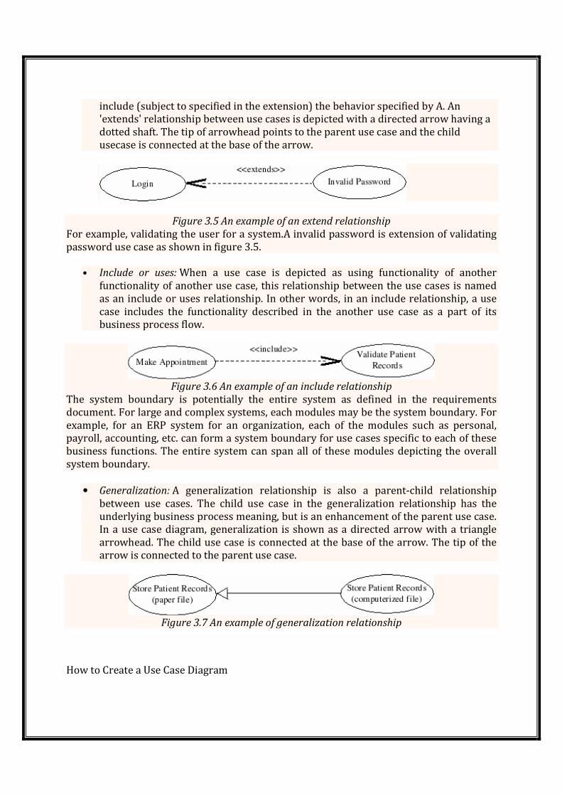
• Communicates: The participation of an actor in a use case is shown by connecting
the actor symbol to use case symbol by a solid path. The actor is said to
'communicates' with the use case. This is only relation between an actor and use
cases. See figure 3.4.
Figure 3.4 Communicates relationship
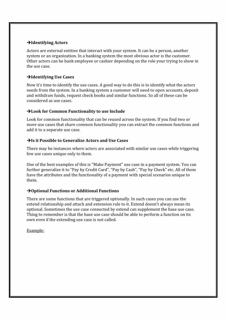
• Extends: An extends shows the relationships between use cases. Relationship
between use case A and use case B indicates that an instance of use case B may
include (subject to specified in the extension) the behavior specified by A. An
'extends' relationship between use cases is depicted with a directed arrow having a
dotted shaft. The tip of arrowhead points to the parent use case and the child
usecase is connected at the base of the arrow.
Figure 3.5 An example of an extend relationship
For example, validating the user for a system.A invalid password is extension of validating
password use case as shown in figure 3.5.
• Include or uses: When a use case is depicted as using functionality of another
functionality of another use case, this relationship between the use cases is named
as an include or uses relationship. In other words, in an include relationship, a use
case includes the functionality described in the another use case as a part of its
business process flow.
Figure 3.6 An example of an include relationship
The system boundary is potentially the entire system as defined in the requirements
document. For large and complex systems, each modules may be the system boundary. For
example, for an ERP system for an organization, each of the modules such as personal,
payroll, accounting, etc. can form a system boundary for use cases specific to each of these
business functions. The entire system can span all of these modules depicting the overall
system boundary.
• Generalization: A generalization relationship is also a parent-child relationship
between use cases. The child use case in the generalization relationship has the
underlying business process meaning, but is an enhancement of the parent use case.
In a use case diagram, generalization is shown as a directed arrow with a triangle
arrowhead. The child use case is connected at the base of the arrow. The tip of the
arrow is connected to the parent use case.
Figure 3.7 An example of generalization relationship
How to Create a Use Case Diagram
����Identifying Actors
Actors are external entities that interact with your system. It can be a person, another
system or an organization. In a banking system the most obvious actor is the customer.
Other actors can be bank employee or cashier depending on the role your trying to show in
the use case.
����Identifying Use Cases
Now it’s time to identify the use cases. A good way to do this is to identify what the actors
needs from the system. In a banking system a customer will need to open accounts, deposit
and withdraw funds, request check books and similar functions. So all of these can be
considered as use cases.
����Look for Common Functionality to use Include
Look for common functionality that can be reused across the system. If you find two or
more use cases that share common functionality you can extract the common functions and
add it to a separate use case.
����Is it Possible to Generalize Actors and Use Cases
There may be instances where actors are associated with similar use cases while triggering
few use cases unique only to them.
One of the best examples of this is “Make Payment” use case in a payment system. You can
further generalize it to “Pay by Credit Card”, “Pay by Cash”, “Pay by Check” etc. All of them
have the attributes and the functionality of a payment with special scenarios unique to
them.
����Optional Functions or Additional Functions
There are some functions that are triggered optionally. In such cases you can use the
extend relationship and attach and extension rule to it. Extend doesn’t always mean its
optional. Sometimes the use case connected by extend can supplement the base use case.
Thing to remember is that the base use case should be able to perform a function on its
own even if the extending use case is not called.
Example:
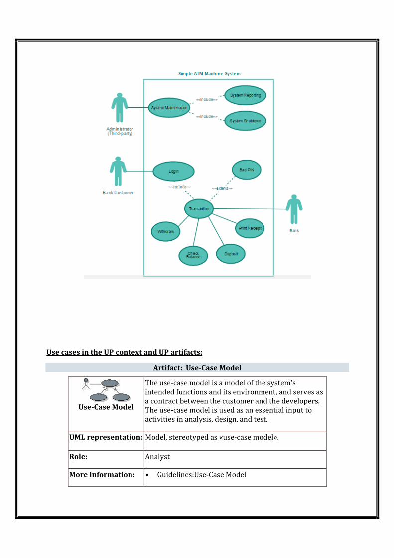
Use cases in the UP context and UP artifacts:
Artifact: Use-Case Model
Use-Case Model
The use-case model is a model of the system's
intended functions and its environment, and serves as
a contract between the customer and the developers.
The use-case model is used as an essential input to
activities in analysis, design, and test.
UML representation: Model, stereotyped as «use-case model».
Role: Analyst
More information: • Guidelines:Use-Case Model
• Guidelines:Use-Case Diagram
• Checkpoints:Use-Case Model
• Templates, Case-Study, Report..
• Purpose
• Properties
• Timing
• Responsibility
• Tailoring
Input to Activities:
• Architectural Analysis
• Review Requirements
• Structure the Use-Case Model
• Use-Case Analysis
Output from Activities:
• Elicit Stakeholders Requests
• Find Actors and Use Cases
• Structure the Use-Case Model
System sequence diagrams for use case model
�A sequence diagram is an interaction
one another and in what order. It is a construct of a message
diagram shows object interactions arranged in time
sometimes called event diagrams
����System behavior is a description
it. One part of that description is a system sequence diagram. Other parts include the
use cases, and system contracts.
�The UML includes sequence diagrams
and the operations initiated by them.
����A system sequence diagra
use case, the events that external actors generate, their order, and inter
An SSD should be done for the main success scenario of the use case, and frequent or
complex alternative scenarios.
�Sequence diagrams, commonly used by developers, model the interactions between
objects in a single use case.
Sequence Diagram Notations
�A sequence diagram is structured in such a way that it represents a timeline which
begins at the top and descends gradually to mark the sequence of interactions. Each object
has a column and the messages exchanged between them are represented by arrows.
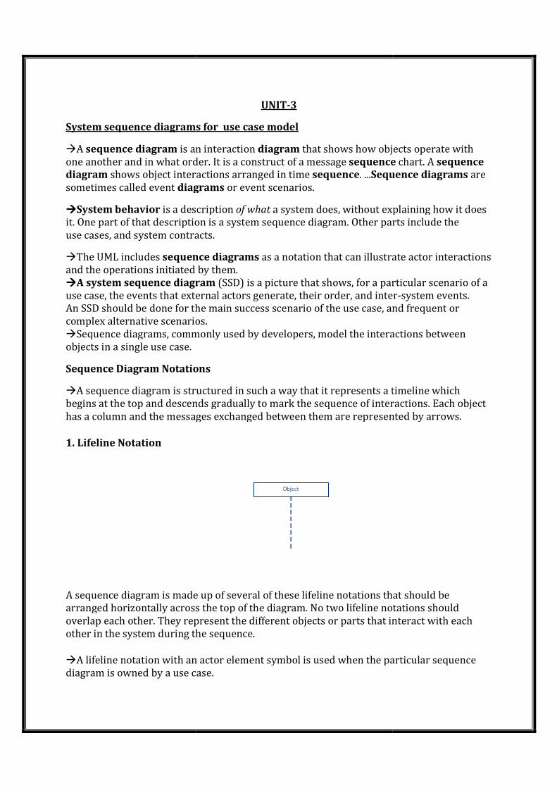
1. Lifeline Notation
A sequence diagram is made up of several of these lifeline notations that should
arranged horizontally across the top of the diagram. No two lifeline notations should
overlap each other. They represent the different objects or parts that interact with each
other in the system during the sequence.
�A lifeline notation with an actor
diagram is owned by a use case.
UNIT-3
System sequence diagrams for use case model
is an interaction diagram that shows how objects operate with
one another and in what order. It is a construct of a message sequence
shows object interactions arranged in time sequence. ...Sequence diagrams
diagrams or event scenarios.
is a description of what a system does, without explaining how it does
that description is a system sequence diagram. Other parts include the
use cases, and system contracts.
sequence diagrams as a notation that can illustrate actor interactions
and the operations initiated by them.
A system sequence diagram (SSD) is a picture that shows, for a particular scenario of a
use case, the events that external actors generate, their order, and inter
An SSD should be done for the main success scenario of the use case, and frequent or
ve scenarios.
Sequence diagrams, commonly used by developers, model the interactions between
Sequence Diagram Notations
A sequence diagram is structured in such a way that it represents a timeline which
and descends gradually to mark the sequence of interactions. Each object
has a column and the messages exchanged between them are represented by arrows.
A sequence diagram is made up of several of these lifeline notations that should
arranged horizontally across the top of the diagram. No two lifeline notations should
overlap each other. They represent the different objects or parts that interact with each
other in the system during the sequence.
A lifeline notation with an actor element symbol is used when the particular sequence
diagram is owned by a use case.
that shows how objects operate with
sequence chart. A sequence
Sequence diagrams are
a system does, without explaining how it does
that description is a system sequence diagram. Other parts include the
as a notation that can illustrate actor interactions
(SSD) is a picture that shows, for a particular scenario of a
use case, the events that external actors generate, their order, and inter-system events.
An SSD should be done for the main success scenario of the use case, and frequent or
Sequence diagrams, commonly used by developers, model the interactions between
A sequence diagram is structured in such a way that it represents a timeline which
and descends gradually to mark the sequence of interactions. Each object
has a column and the messages exchanged between them are represented by arrows.
A sequence diagram is made up of several of these lifeline notations that should be
arranged horizontally across the top of the diagram. No two lifeline notations should
overlap each other. They represent the different objects or parts that interact with each
element symbol is used when the particular sequence
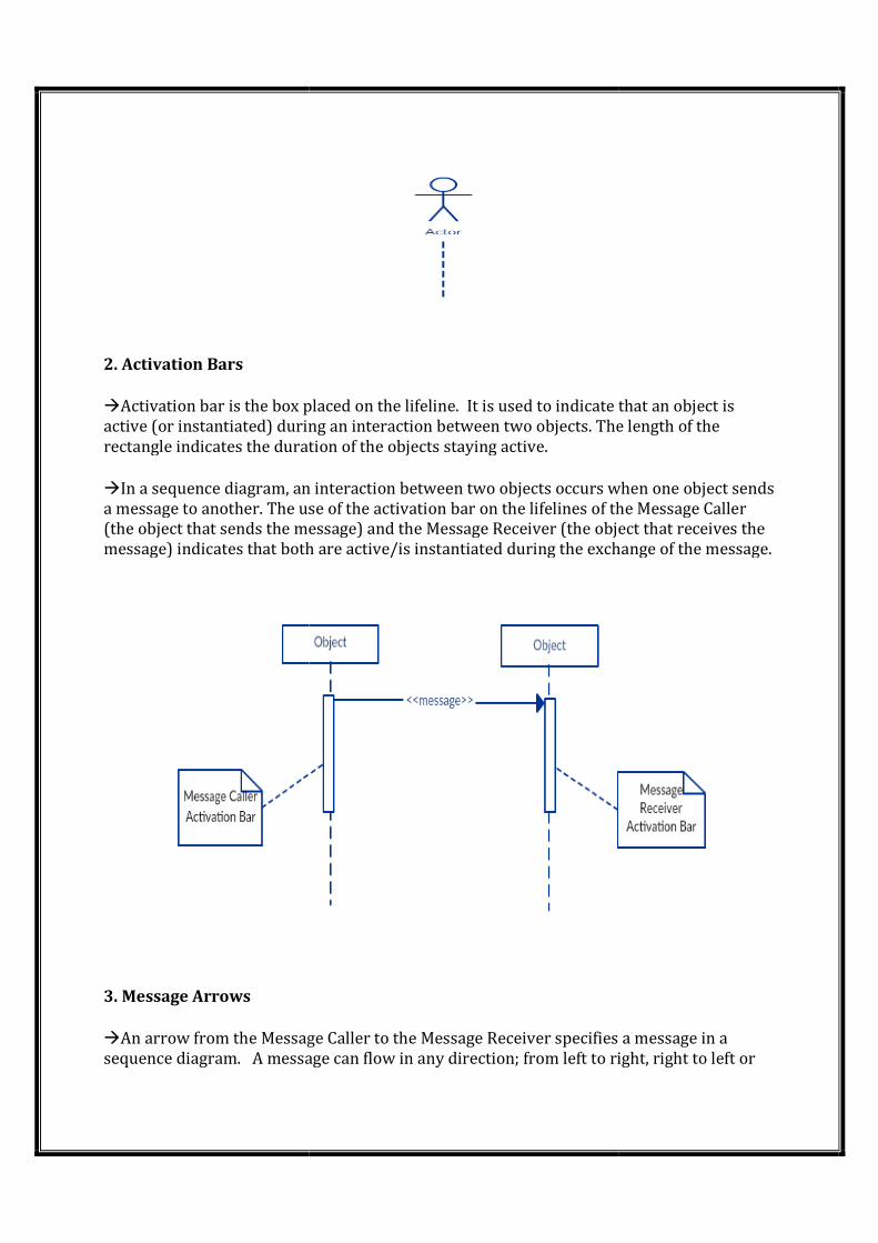
2. Activation Bars
�Activation bar is the box placed on the lifeline.
active (or instantiated) during an interaction between two
rectangle indicates the duration of the objects staying active.
�In a sequence diagram, an interaction between two objects occurs when one object sends
a message to another. The use of the activation bar on the lifelines of the
(the object that sends the message) and the Message Receiver (the object that receives the
message) indicates that both are active/is instantiated during the exchange of the message.
3. Message Arrows
�An arrow from the Message Caller to t
sequence diagram. A message can flow in any direction; from left to right, right to left or
Activation bar is the box placed on the lifeline. It is used to indicate that an object is
active (or instantiated) during an interaction between two objects. The length of the
rectangle indicates the duration of the objects staying active.
In a sequence diagram, an interaction between two objects occurs when one object sends
a message to another. The use of the activation bar on the lifelines of the
(the object that sends the message) and the Message Receiver (the object that receives the
message) indicates that both are active/is instantiated during the exchange of the message.
An arrow from the Message Caller to the Message Receiver specifies a message in a
A message can flow in any direction; from left to right, right to left or
It is used to indicate that an object is
objects. The length of the
In a sequence diagram, an interaction between two objects occurs when one object sends
a message to another. The use of the activation bar on the lifelines of the Message Caller
(the object that sends the message) and the Message Receiver (the object that receives the
message) indicates that both are active/is instantiated during the exchange of the message.
he Message Receiver specifies a message in a
A message can flow in any direction; from left to right, right to left or
back to the Message Caller itself. While you can describe the message being sent from one
object to the other on the arrow, with different arrowheads you can indicate the type of
message being sent or received.
�The message arrow comes with a description, which is known as a message signature, on
it. The format for this message signature is below. All parts except the me
optional.
attribute = message_name (arguments): return_type
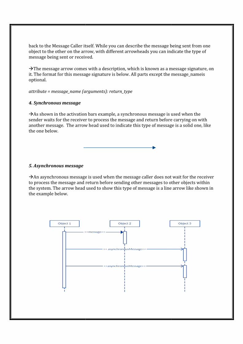
4. Synchronous message
�As shown in the activation bars example, a synchronous message is used when the
sender waits for the receiver to process the message and return before
another message. The arrow head used to indicate this type of message is a solid one, like
the one below.
5. Asynchronous message
�An asynchronous message is used when the message caller does not wait for the receiver
to process the message and return before sending other messages to other objects within
the system. The arrow head used to show this type of message is a line arrow like shown in
the example below.
back to the Message Caller itself. While you can describe the message being sent from one
arrow, with different arrowheads you can indicate the type of
message being sent or received.
The message arrow comes with a description, which is known as a message signature, on
it. The format for this message signature is below. All parts except the me
attribute = message_name (arguments): return_type
As shown in the activation bars example, a synchronous message is used when the
sender waits for the receiver to process the message and return before
The arrow head used to indicate this type of message is a solid one, like
An asynchronous message is used when the message caller does not wait for the receiver
sage and return before sending other messages to other objects within
the system. The arrow head used to show this type of message is a line arrow like shown in
back to the Message Caller itself. While you can describe the message being sent from one
arrow, with different arrowheads you can indicate the type of
The message arrow comes with a description, which is known as a message signature, on
it. The format for this message signature is below. All parts except the message_nameis
As shown in the activation bars example, a synchronous message is used when the
sender waits for the receiver to process the message and return before carrying on with
The arrow head used to indicate this type of message is a solid one, like
An asynchronous message is used when the message caller does not wait for the receiver
sage and return before sending other messages to other objects within
the system. The arrow head used to show this type of message is a line arrow like shown in
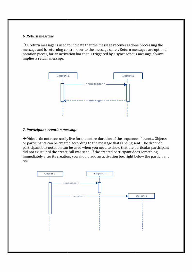
6. Return message
�A return message is used to indicate that the message
message and is returning control over to the message caller. Return messages are optional
notation pieces, for an activation bar that is triggered by a synchronous message always
implies a return message.
7. Participant creation message
�Objects do not necessarily live for the entire duration of the sequence of events. Objects
or participants can be created according to the message that is being sent. The dropped
participant box notation can be used when you need to show t
did not exist until the create call was sent.
immediately after its creation, you should add an activation box right below the participant
box.
A return message is used to indicate that the message receiver is done processing the
message and is returning control over to the message caller. Return messages are optional
notation pieces, for an activation bar that is triggered by a synchronous message always
reation message
Objects do not necessarily live for the entire duration of the sequence of events. Objects
or participants can be created according to the message that is being sent. The dropped
participant box notation can be used when you need to show that the particular participant
did not exist until the create call was sent. If the created participant does something
immediately after its creation, you should add an activation box right below the participant
receiver is done processing the
message and is returning control over to the message caller. Return messages are optional
notation pieces, for an activation bar that is triggered by a synchronous message always
Objects do not necessarily live for the entire duration of the sequence of events. Objects
or participants can be created according to the message that is being sent. The dropped
hat the particular participant
If the created participant does something
immediately after its creation, you should add an activation box right below the participant
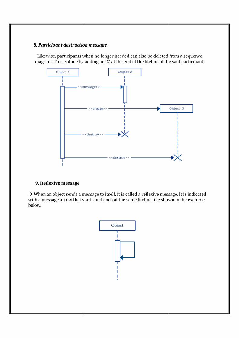
8. Participant destruction message
Likewise, participants when no longer needed
diagram. This is done by adding an ‘X’ at the end of the lifeline of the said participant.
9. Reflexive message
� When an object sends a message to itself, it is called a ref
with a message arrow that starts and ends at the same lifeline
below.
8. Participant destruction message
Likewise, participants when no longer needed can also be deleted from a sequence
diagram. This is done by adding an ‘X’ at the end of the lifeline of the said participant.
When an object sends a message to itself, it is called a reflexive message. It is indicated
with a message arrow that starts and ends at the same lifeline like shown in the example
can also be deleted from a sequence
diagram. This is done by adding an ‘X’ at the end of the lifeline of the said participant.
lexive message. It is indicated
like shown in the example
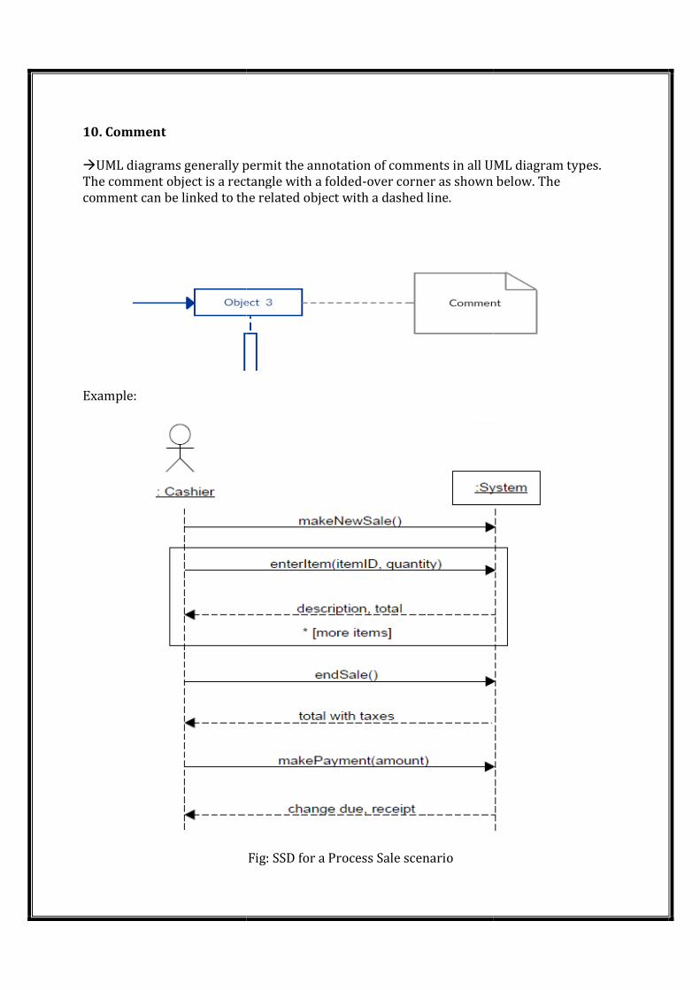
10. Comment
�UML diagrams generally permit
The comment object is a rectangle with a folded
comment can be linked to the
Example:
permit the annotation of comments in all UML diagram types
The comment object is a rectangle with a folded-over corner as shown below. The
comment can be linked to the related object with a dashed line.
Fig: SSD for a Process Sale scenario
UML diagram types.
over corner as shown below. The
Domain model:
A domain model is widely used as a source of inspiration for designing software objects,
and will be a required input to several subsequent artifacts
A domain model illustrates meaningful (to the modelers) conceptual classes in a problem
domain; it is the most important artifact to create during object-oriented analysis.
A domain model is a visual representation of conceptual classes or real-world objects in a
domain of interest
They have also been called conceptual models, domain object models, and analysis
object models.
Why do a domain model?
Gives a conceptual framework of the things in the problem space.
Features of a domain model
• Domain classes – each domain class denotes a type of object.
• Attributes – an attribute is the description of a named slot of a specified type in a domain
class; each instance of the class separately holds a value.
• Associations – an association is a relationship between two (or more) domain classes that
describes links between their object instances. Associations can have roles, describing the
multiplicity and participation of a class in the relationship.
• Additional rules – complex rules that cannot be shown with symbolically can be shown
with attached notes.
Domain classes?
• Each domain class denotes a type of object. It is a descriptor for a set of things that share
common features.
Classes can be:-
• Business objects - represent things that are manipulated in the business e.g. Order.
• Real world objects – things that the business keeps track of e.g. Contact, Site.
• Events that transpire - e.g. sale and payment.
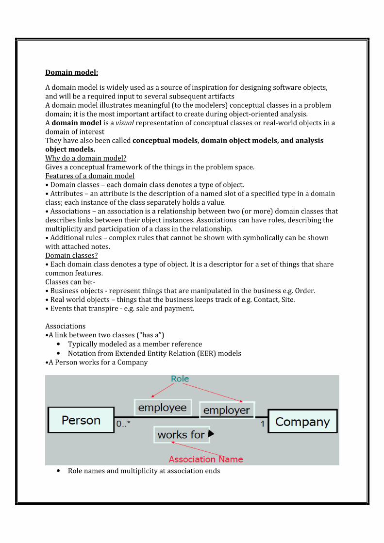
Associations
•A link between two classes (“has a”)
• Typically modeled as a member reference
• Notation from Extended Entity Relation (EER) models
•A Person works for a Company
• Role names and multiplicity at association ends
• Direction arrow to aid reading of association name
Adding Association
•An association is a relationship between classes that indicates some meaningful and
interesting connection.
•In the UML, associations are defined as “the semantic relationship between two or more
classifiers that involve connections among their instances.”
Adding Attributes
•An attribute is a logical data value of an object.
•Include the following attributes in a domain model: Those for which the requirements
suggest a need to remember information.
•An attribute can be a more complex type whose structure is unimportant to the problem,
so we treat it like a simple type
•UML Attributes Notation: Attributes are shown in the second compartment of the class
box
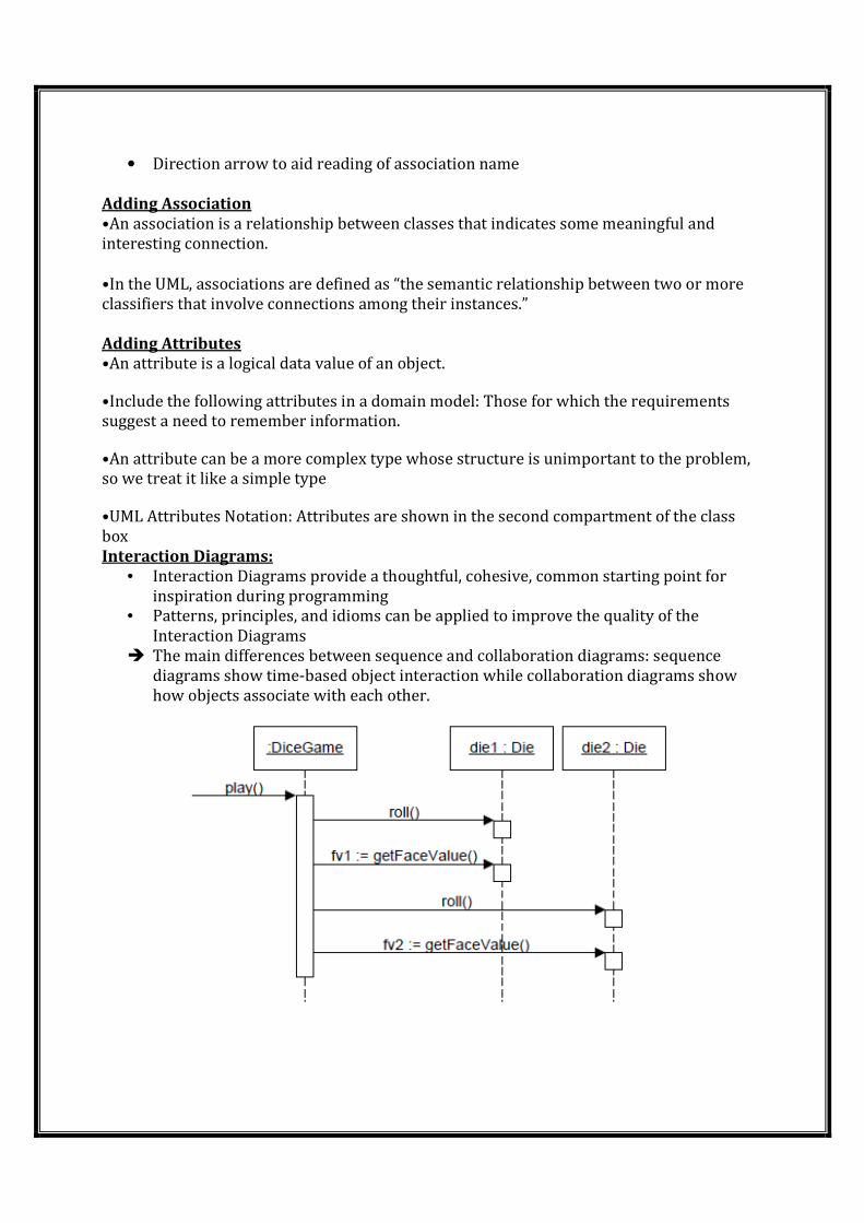
Interaction Diagrams:
• Interaction Diagrams provide a thoughtful, cohesive, common starting point for
inspiration during programming
• Patterns, principles, and idioms can be applied to improve the quality of the
Interaction Diagrams
� The main differences between sequence and collaboration diagrams: sequence
diagrams show time-based object interaction while collaboration diagrams show
how objects associate with each other.
GRASP Design patterns:
�Stands for General Responsibility Assignment Software Patterns
A Design Model may have
• hundreds or even thousands of software classes and
• hundreds or thousands of responsibilities to be assigned.
During objectdesign, when interactions between objects are defined; we make choices
about the assignment of responsibilities to software classes
Responsibilities and Methods
The UML defines a responsibility as "a contract or obligation of a classifier".
Responsibilities are related to the obligations of an object in terms of its behavior.
Basically, these responsibilities are of the following two types: knowing, doing
Doing responsibilities of an object include:
� doing something itself, such as creating an object or
� doing a calculation
� initiating action in other objects
� controlling and coordinating activities in other objects
Knowing responsibilities of an object include:
� knowing about private encapsulated data
� knowing about related objects
� knowing about things it can derive or calculate
How to Apply the GRASP Patterns
The following sections present the first five GRASP patterns:
� Information Expert
� Creator
� High Cohesion
� Low Coupling
� Controller
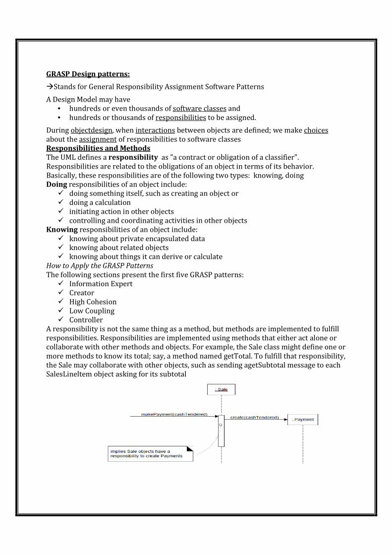
A responsibility is not the same thing as a method, but methods are implemented to fulfill
responsibilities. Responsibilities are implemented using methods that either act alone or
collaborate with other methods and objects. For example, the Sale class might define one or
more methods to know its total; say, a method named getTotal. To fulfill that responsibility,
the Sale may collaborate with other objects, such as sending agetSubtotal message to each
SalesLineltem object asking for its subtotal
�Indicates that Sale objects have been given a responsibility to create Payments,
which is invoked with a makePayment message and handled with a corresponding
makePayment method. Furthermore, the fulfillment of this responsibility requires
collaboration to create the SalesLineltem object and invoke its constructor.
• a pattern is a named problem/solution pair that can be applied in new context,
with advice on how to apply it in novel situations and discussion of its trade-offs.
• "One person’s pattern is another person’s primitive building block" is an object
technology adage illustrating the vagueness of what can be called a pattern
Repeating Patterns
• New pattern could be considered an oxymoron, if it describes a new idea. The
very term "pattern" is meant to suggest a repeating thing. The point of patterns is
not to express new design ideas.
• GRASP: Patterns of General Principles in Assigning Responsibilities
• To summarize the preceding introduction:
• The skillful assignment of responsibilities is extremely important in object
design. Determining the assignment of responsibilities often occurs during
The creation of interaction diagrams, and certainly during programming.
• patterns are named problem/solution pairs that codify good advice and
principles often related to the assignment of responsibilities.
How to Apply the GRASP Patterns
• The following sections present the first five GRASP patterns:
• • Information Expert
• • Creator
• • High Cohesion
• • Low Coupling
• • Controller
Information Expert (or Expert)
Solution Assign a responsibility to the information expert.the class that has the
informationnecessary to fulfill the responsibility.
Problem What is a general principle of assigning responsibilities to objects?
A Design Model may define hundreds or thousands of software classes, and an application
may require hundreds or thousands of responsibilities to be fulfilled. During object design,
when the interactions between objects are defined, we make choices about the assignment
of responsibilities to software classes.
Creator
Solution Assign class B the responsibility to create an instance of class A if one or more of
the following is true:
. B aggregates A objects.
. B contains A objects.
. B records instances of A objects.
. B closely uses A objects.
. B has the initializing data that will be passed to A when it is created (thus B is an Expert
with respect to creating A).
B is a creator of A objects.
If more than one option applies, prefer a class B which aggregates or contains class A.
Problem Who should be responsible for creating a new instance of some class?
The creation of objects is one of the most common activities in an object-oriented system.
Consequently, it is useful to have a general principle for the assignment of creation
responsibilities. Assigned well, the design can support low coupling, increased clarity,
encapsulation, and reusability.
Low Coupling
Solution Assign a responsibility so that coupling remains low.
Problem How to support low dependency, low change impact, and increased reuse?
Coupling is a measure of how strongly one element is connected to, has knowledge of, or
relies on other elements. An element with low (or weak) coupling is not dependent on too
many other elements; "too many" is context-dependent, but will be examined. These
elements include classes, subsystems, systems, and so on.
A class with high (or strong) coupling relies on many other classes. Such classes may be
undesirable; some suffer from the following problems:
. Changes in related classes force local changes.
. Harder to understand in isolation.
. Harder to reuse because its use requires the additional presence of the classes on which it
is dependent.
High cohesion:
Solution Assign a responsibility so that cohesion remains high.
Problem How to keep complexity manageable?
In terms of object design, cohesion (or more specifically, functional cohesion) is a measure
of how strongly related and focused the responsibilities of an element are. An element with
highly related responsibilities, and which does not do a tremendous amount of work, has
high cohesion. These elements include classes, subsystems, and so on.
A class with low cohesion does many unrelated things, or does too much work. Such classes
are undesirable; they suffer from the following problems:
. hard to comprehend
. hard to reuse
. hard to maintain
. delicate; constantly effected by change
Low cohesion classes often represent a very "large grain" of abstraction, or have taken on
responsibilities that should have been delegated to other objects.
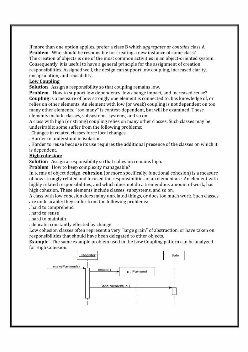
Example The same example problem used in the Low Coupling pattern can be analyzed
for High Cohesion.
Controller
Solution Assign the responsibility for receiving or handling a system event message to a
class representing one of the following choices:
. Represents the overall system, device, or subsystem (facade controller).
. Represents a use case scenario within which the system event occurs, often
named<UseCaseName>Handler, <UseCaseName>Coordinator, or
<Use-CaseName>Session (use-case or session controller).
o Use the same controller class for all system events in the same use case scenario.
o Informally, a session is an instance of a conversation with an actor. Sessions can be of any
length, but are often organized in terms of use cases
Problem Who should be responsible for handling an input system event?
An input system event is an event generated by an external actor. They are associated
with system operationsoperations of the system in response to system events, just as
messages and methods are related.
For example, when a cashier using a POS terminal presses the "End Sale" button, he is
generating a system event indicating "the sale has ended." Similarly, when a writer using a
word processor presses the "spell check" button, he is generating a system event indicating
"perform a spell check."
A Controller is a non-user interface object responsible for receiving or handling a system
event. A Controller defines the method for the system operation.
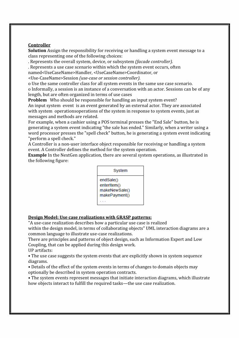
Example In the NextGen application, there are several system operations, as illustrated in
the following figure:
Design Model: Use case realizations with GRASP patterns:
"A use-case realization describes how a particular use case is realized
within the design model, in terms of collaborating objects" UML interaction diagrams are a
common language to illustrate use-case realizations.
There are principles and patterns of object design, such as Information Expert and Low
Coupling, that can be applied during this design work.
UP artifacts:
• The use case suggests the system events that are explicitly shown in system sequence
diagrams.
• Details of the effect of the system events in terms of changes to domain objects may
optionally be described in system operation contracts.
• The system events represent messages that initiate interaction diagrams, which illustrate
how objects interact to fulfill the required tasks—the use case realization.
• The interaction diagrams involve message interaction between software objects whose
names are sometimes inspired by the names of conceptual classes in the Domain Model,
plus other classes of objects.
Design Class diagrams in each MVC layer Mapping Design to Code:
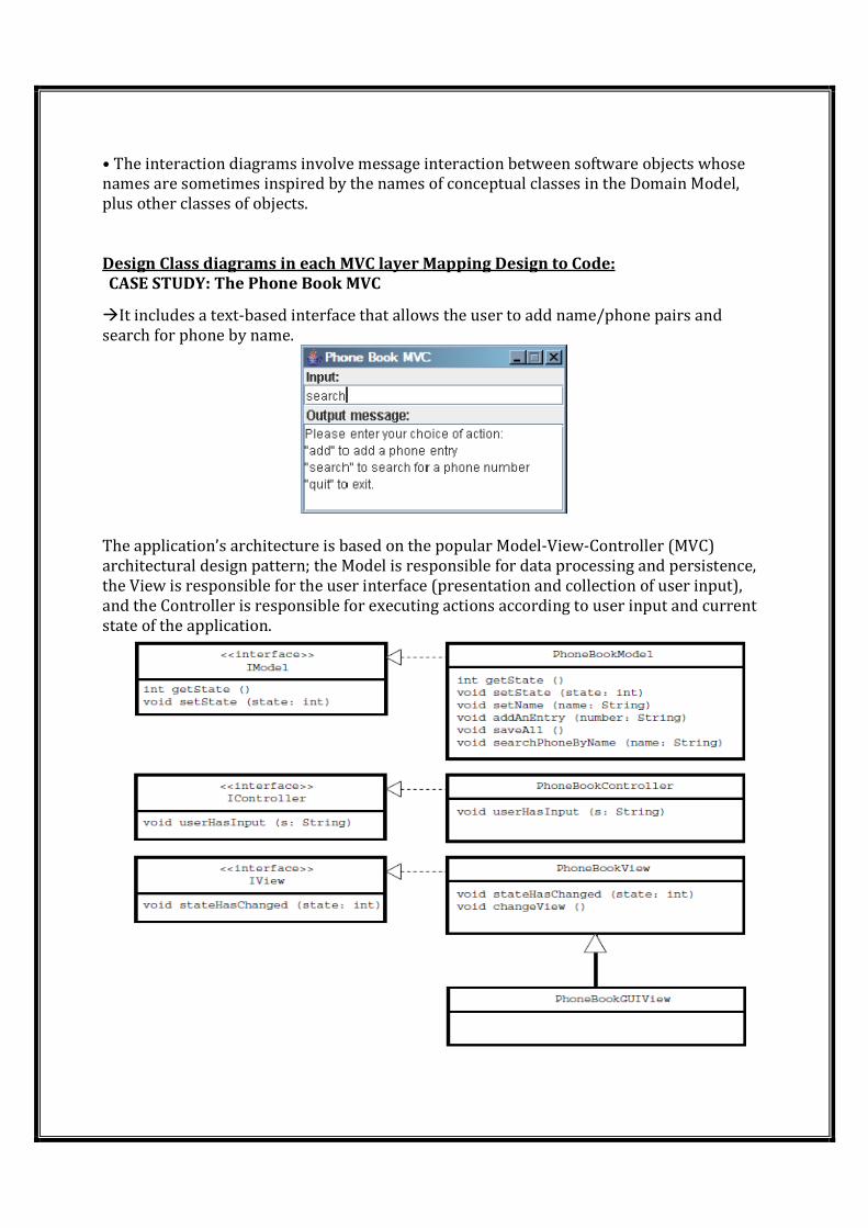
CASE STUDY: The Phone Book MVC
�It includes a text-based interface that allows the user to add name/phone pairs and
search for phone by name.
The application’s architecture is based on the popular Model-View-Controller (MVC)
architectural design pattern; the Model is responsible for data processing and persistence,
the View is responsible for the user interface (presentation and collection of user input),
and the Controller is responsible for executing actions according to user input and current
state of the application.
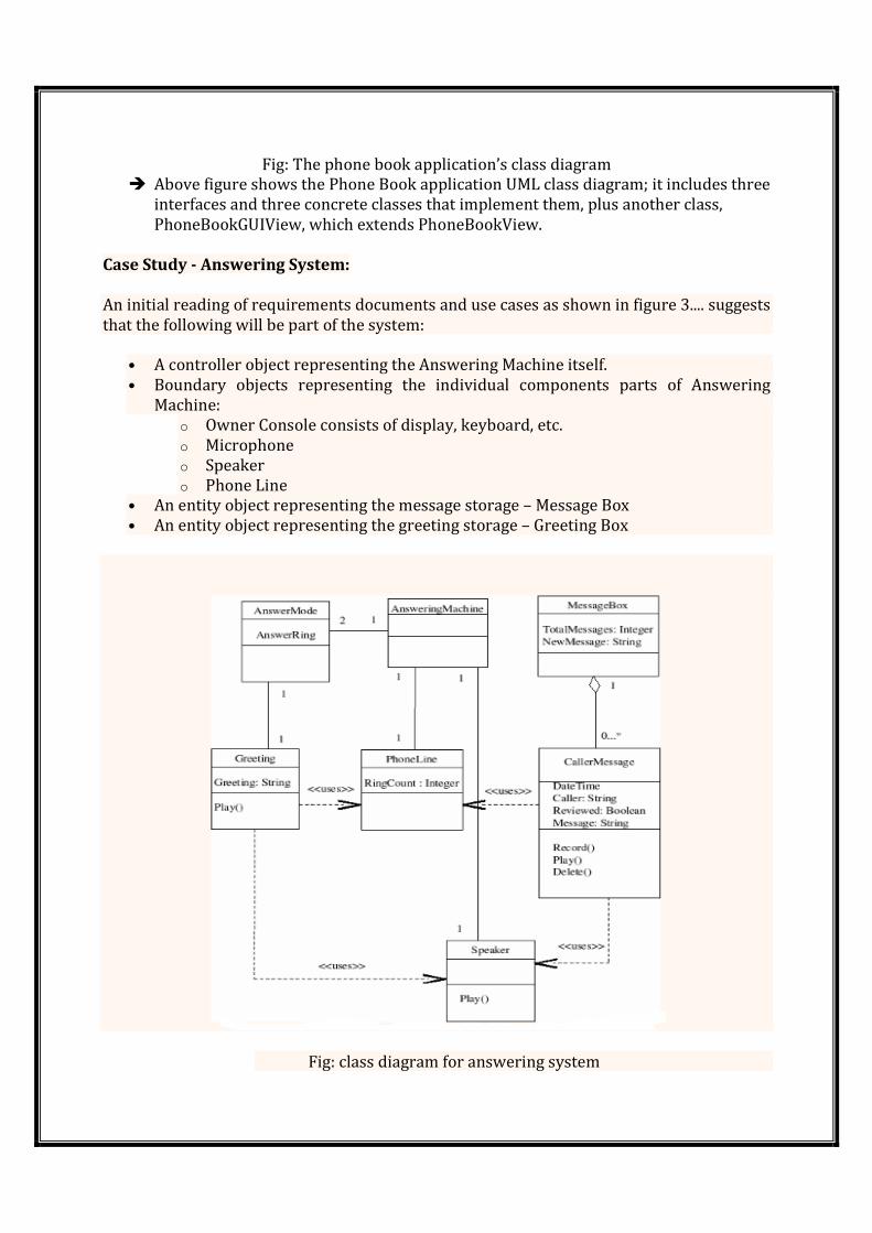
Fig: The phone book application’s class diagram
� Above figure shows the Phone Book application UML class diagram; it includes three
interfaces and three concrete classes that implement them, plus another class,
PhoneBookGUIView, which extends PhoneBookView.
Case Study - Answering System:
An initial reading of requirements documents and use cases as shown in figure 3.... suggests
that the following will be part of the system:
• A controller object representing the Answering Machine itself.
• Boundary objects representing the individual components parts of Answering
Machine:
o Owner Console consists of display, keyboard, etc.
o Microphone
o Speaker
o Phone Line
• An entity object representing the message storage – Message Box
• An entity object representing the greeting storage – Greeting Box
Fig: class diagram for answering system
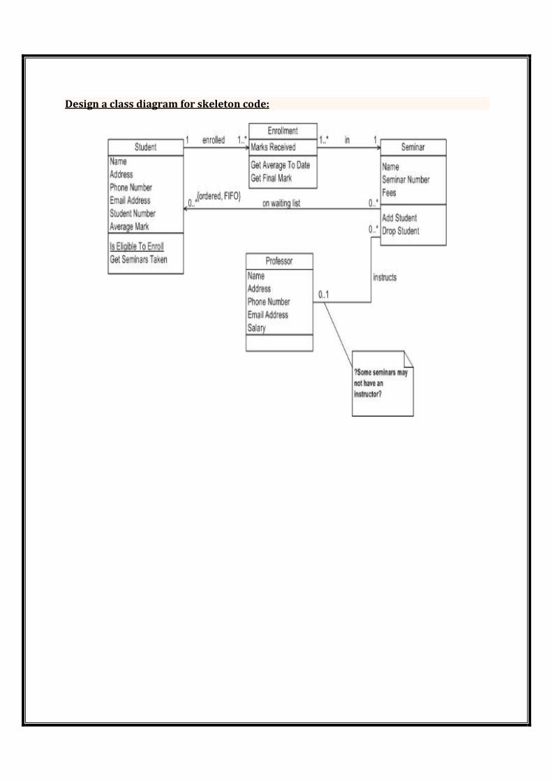
Design a class diagram for skeleton code:
UNIT-4
Fabrication
We have explored what are patterns and GRASP (in part I), Information Expert in part II andCreator in part II, Controller in Part IV, “Low Coupling” in part V and “High Cohesion” in partVI and Polymorphism in Part VII. In this part VIII, we would focus on next GRASP pattern named “Pure Fabrication”. Generally working on existing system, everybody fumbles on a dilemma about changing the existing design. Imagine scenario where the existing classes have low cohesion and high coupling rather it violates the High cohesion and low coupling. It would be overkill to change the existing classes in entirety or even it could be unviable from the perspective of budget(and time). The principle behind this pattern is to resolve such a dilemma by deciding on “Whom to assign responsibilities when assigning to existing domain classesviolates High cohesion and Low coupling?” These domain classes are generally theInformation Expert classes. Problem:Who should be responsible when an expert violates high cohesion and low
coupling? Solution: Assign the responsibility for handling a system event message to a class which is newfictitious (artificial) and doesn’t represent a concept in domain. Assign the cohesive set of responsibilities to such class in order to support high cohesion, low coupling and reuse. As this class is fictitious hence it can be called as its outcome of imagination or pure
fabrication. Approach:
Step I: Closely look at domain/ design model and locate the classes with low cohesionand high coupling. e.g. “Sale” class doing all the database operation related to “Sale”
Step II: Create a new class to take the responsibility of functionality causing lowcohesion and high coupling.
Description
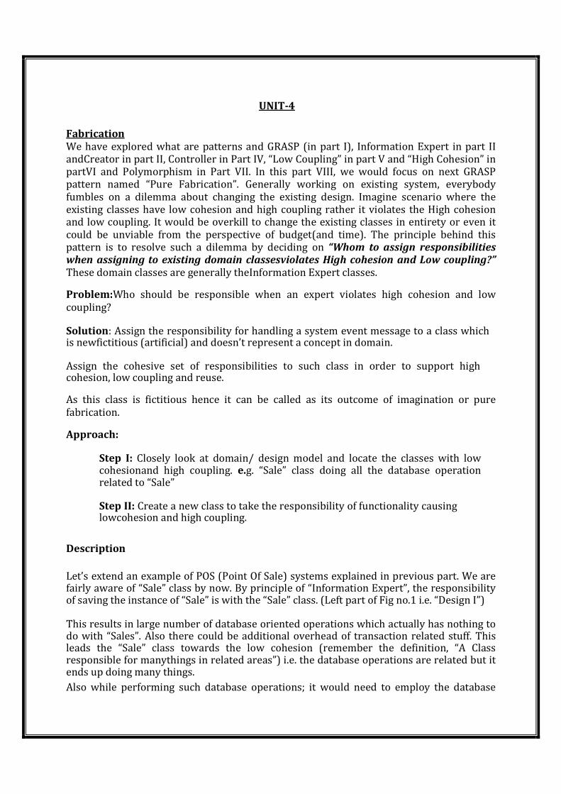
Let’s extend an example of POS (Point Of Sale) systems explained in previous part. We are fairly aware of “Sale” class by now. By principle of “Information Expert”, the responsibility of saving the instance of “Sale” is with the “Sale” class. (Left part of Fig no.1 i.e. “Design I”) This results in large number of database oriented operations which actually has nothing to do with “Sales”. Also there could be additional overhead of transaction related stuff. This leads the “Sale” class towards the low cohesion (remember the definition, “A Class responsible for manythings in related areas”) i.e. the database operations are related but it ends up doing many things. Also while performing such database operations; it would need to employ the database
interface culminating into low coupling. In fact, such database operations are generic in nature and have potential for reuse.The solution is to create a new class say “StorageAgent“which would interact with database interface and saves the instance of “Sale” class. As “Sale” would be spared from saving its own instance into database thus giving rise to high cohesion and low coupling. In this fashion the “StorageAgent” is also highly cohesive by performing the sole responsibility of saving the instance / object. (Right part of Fig no.1 i.e. “Design II”).
As demonstrated, the “StorageAgent” is a generic and reusable class. All such classes i.e. pure fabrication (rather purely fabricated) classes are function centric. Other good examples are the adapters, observers and one would find many examples in a service layer.As per Larman, there are 2 approaches of designing which the pure fabrication is the behavioural way. Representation decomposition: Designing the objects the way they represent in the domain
· Behavioural decomposition: Designing the objects the way they do. These are
function centric or encapsulate algorithm Commonly, the pure fabrication is used to place / encapsulate the algorithm or function which doesn’t fit well in other classes. Benefits:
· Supports Low Coupling
· Results in high cohesion · Promotes reusability
Liabilities /Contradictions:
· Sometimes such design may result into bunch of classes having a single method which is a kind of overkill.
Singleton: Intent
Ensure a class has only one instance, and provide a global point of access to it. Encapsulated "just-in-time initialization" or "initialization on first use".
Problem
Application needs one, and only one, instance of an object. Additionally, lazy initialization and global access are necessary. Discussion
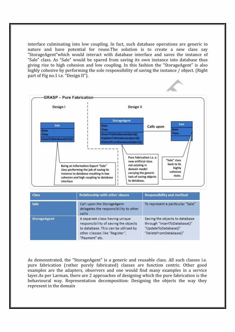
Make the class of the single instance object responsible for creation, initialization, access, and enforcement. Declare the instance as a private static data member. Provide a public static ember function that encapsulates all initialization code, and provides access to the instance.The client calls the accessor function (using the class name and scope resolution operator) whenever a reference to the single instance is required. Singleton should be considered only if all three of the following criteria are satisfied:
o Ownership of the single instance cannot be reasonably assigned
o Lazy initialization is desirable o Global access is not otherwise provided for
If ownership of the single instance, when and how initialization occurs, and global access are not issues, Singleton is not sufficiently interesting. The Singleton pattern can be extended to support access to an application-specific number of instances. The "static member function accessor" approach will not support sub classing of the Singleton class.
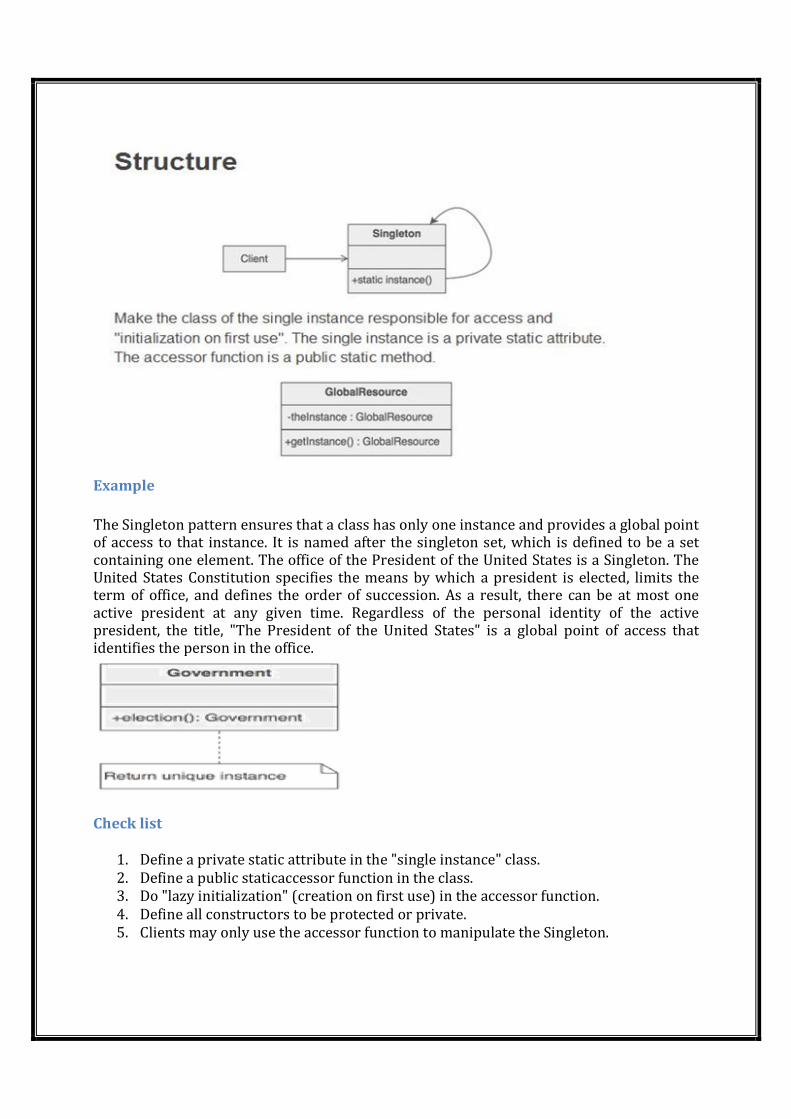
Example
The Singleton pattern ensures that a class has only one instance and provides a global point of access to that instance. It is named after the singleton set, which is defined to be a set containing one element. The office of the President of the United States is a Singleton. The United States Constitution specifies the means by which a president is elected, limits the term of office, and defines the order of succession. As a result, there can be at most one active president at any given time. Regardless of the personal identity of the active president, the title, "The President of the United States" is a global point of access that identifies the person in the office.
Check list
1. Define a private static attribute in the "single instance" class. 2. Define a public staticaccessor function in the class.
3. Do "lazy initialization" (creation on first use) in the accessor function. 4. Define all constructors to be protected or private. 5. Clients may only use the accessor function to manipulate the Singleton.
Rules of thumb
o Abstract Factory, Builder, and Prototype can use Singleton in their implementation.
o Facade objects are often Singletons because only one Facade object is required.
o State objects are often Singletons. o The advantage of Singleton over global variables is that you are absolutely sure of the
number of instances when you use Singleton, and, you can change your mind and manage any number of instances.
o The Singleton design pattern is one of the most inappropriately used patterns. Singletons are intended to be used when a class must have exactly one instance, no more, no less. Designers frequently use Singletons in a misguided attempt to replace global variables. A Singleton is, for intents and purposes, a global variable. The Singleton does not do away with the global; it merely renames it.
o When is Singleton unnecessary? Short answer: most of the time. Long answer: when it's simpler to pass an object resource as a reference to the objects that need it, rather than letting objects access the resource globally. The real problem with Singletons is that they give you such a good excuse not to think carefully about the appropriate visibility of an object. Finding the right balance of exposure and protection for an object is critical for maintaining flexibility.
o Our group had a bad habit of using global data, so I did a study group on Singleton. The next thing I know Singletons appeared everywhere and none of the problems related to global data went away. The answer to the global data question is not, "Make it a Singleton." The answer is, "Why in the hell are you using global data?" Changing the name doesn't change the problem. In fact, it may make it worse because it gives you the opportunity to say, "Well I'm not doing that, I'm doing this" – even though this and that are the same thing.
Factory Intent � Define an interface for creating an object, but let subclasses decide which class
to instantiate. Factory Method lets a class defer instantiation to subclasses. � Defining a "virtual" constructor. � The new operator considered harmful.
Problem A framework needs to standardize the architectural model for a range of applications, but allow for individual applications to define their own domain objects and provide for their instantiation.
Discussion Factory Method is to creating objects as Template Method is to implementing an algorithm. A superclass specifies all standard and generic behavior (using pure virtual "placeholders" for creation steps), and then delegates the creation details to subclasses that are supplied by the client. Factory Method makes a design more customizable and only a little more complicated. Other design patterns require new classes, whereas Factory Method only requires a new operation. People often use Factory Method as the standard way to create objects; but it isn't necessary if: the class that's instantiated never changes, or instantiation
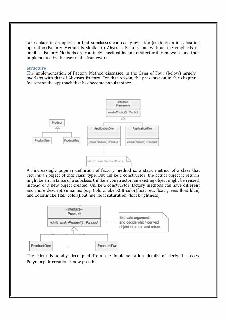
takes place in an operation that subclasses can easily override (such as an initialization operation).Factory Method is similar to Abstract Factory but without the emphasis on families. Factory Methods are routinely specified by an architectural framework, and then implemented by the user of the framework.
Structure The implementation of Factory Method discussed in the Gang of Four (below) largely overlaps with that of Abstract Factory. For that reason, the presentation in this chapter focuses on the approach that has become popular since.
An increasingly popular definition of factory method is: a static method of a class that returns an object of that class' type. But unlike a constructor, the actual object it returns might be an instance of a subclass. Unlike a constructor, an existing object might be reused, instead of a new object created. Unlike a constructor, factory methods can have different and more descriptive names (e.g. Color.make_RGB_color(float red, float green, float blue) and Color.make_HSB_color(float hue, float saturation, float brightness)
The client is totally decoupled from the implementation details of derived classes.
Polymorphic creation is now possible.
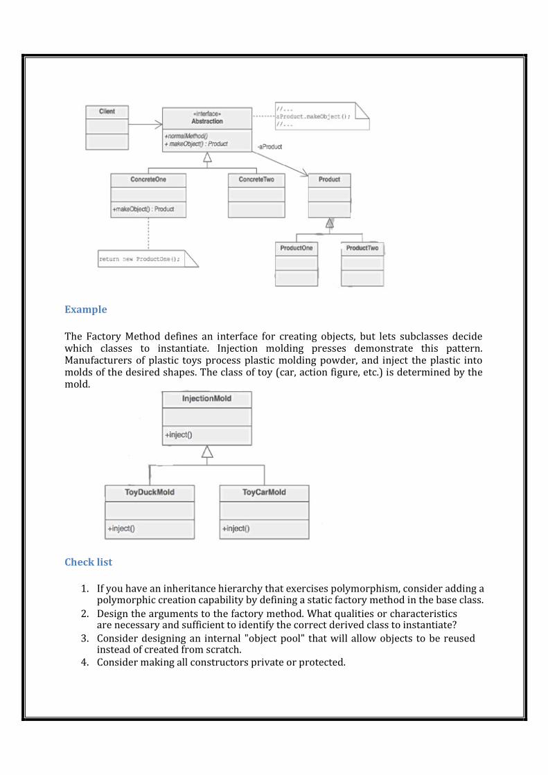
Example
The Factory Method defines an interface for creating objects, but lets subclasses decide which classes to instantiate. Injection molding presses demonstrate this pattern. Manufacturers of plastic toys process plastic molding powder, and inject the plastic into molds of the desired shapes. The class of toy (car, action figure, etc.) is determined by the mold.
Check list
1. If you have an inheritance hierarchy that exercises polymorphism, consider adding a
polymorphic creation capability by defining a static factory method in the base class. 2. Design the arguments to the factory method. What qualities or characteristics
are necessary and sufficient to identify the correct derived class to instantiate? 3. Consider designing an internal "object pool" that will allow objects to be reused
instead of created from scratch. 4. Consider making all constructors private or protected.
Rules of thumb
� Abstract Factory classes are often implemented with Factory Methods, but they can
be implemented using Prototype. � Factory Methods are usually called within Template Methods. � Factory Method: creation through inheritance. Prototype: creation through
delegation. � Often, designs start out using Factory Method (less complicated, more customizable,
subclasses proliferate) and evolve toward Abstract Factory, Prototype, or Builder (more flexible, more complex) as the designer discovers where more flexibility is needed.
� Prototype doesn't require sub classing, but it does require an Initialize operation. Factory Method requires subclassing, but doesn't require Initialize.
� The advantage of a Factory Method is that it can return the same instance multiple times, or can return a subclass rather than an object of that exact type.
� Some Factory Method advocates recommend that as a matter of language design (or failing that, as a matter of style) absolutely all constructors should be private or protected. It's no one else's business whether a class manufactures a new object or recycles an old one.
� The new operator considered harmful. There is a difference between requesting an object and creating one. The new operator always creates an object, and fails to encapsulate object creation. A Factory Method enforces that encapsulation, and allows an object to be requested without inextricable coupling to the act of creation.
Façade:
Intent � Provide a unified interface to a set of interfaces in a subsystem. Facade defines
a higher-level interface that makes the subsystem easier to use. � Wrap a complicated subsystem with a simpler interface.
Problem A segment of the client community needs a simplified interface to the overall functionality of a complex subsystem.
Discussion Facade discusses encapsulating a complex subsystem within a single interface object. This reduces the learning curve necessary to successfully leverage the subsystem. It also promotes decoupling the subsystem from its potentially many clients. On the other hand, if the Facade isthe only access point for the subsystem, it will limit the features and flexibility that "power users" may need.
The Facade object should be a fairly simple advocate or facilitator. It should not become an all-knowing oracle or "god" object.
Structure Facade takes a "riddle wrapped in an enigma shrouded in mystery", and interjects a wrapper that tames the amorphous and inscrutable mass of software.
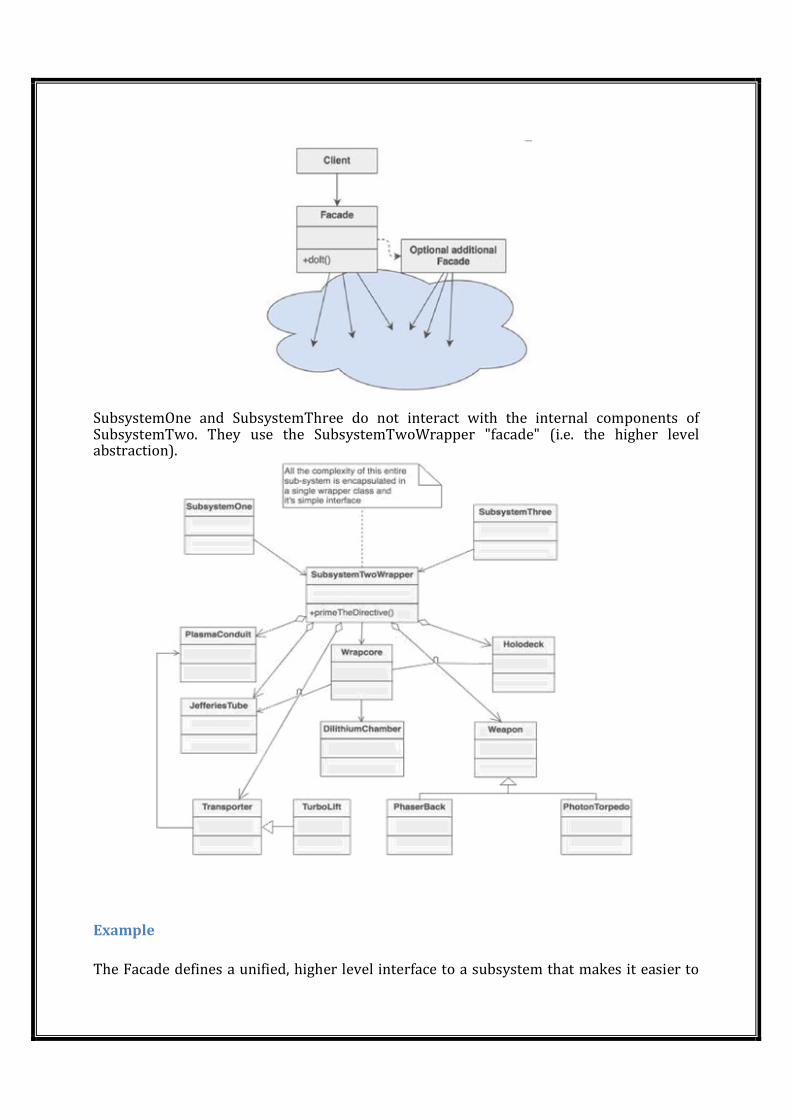
SubsystemOne and SubsystemThree do not interact with the internal components of SubsystemTwo. They use the SubsystemTwoWrapper "facade" (i.e. the higher level abstraction).
Example
The Facade defines a unified, higher level interface to a subsystem that makes it easier to
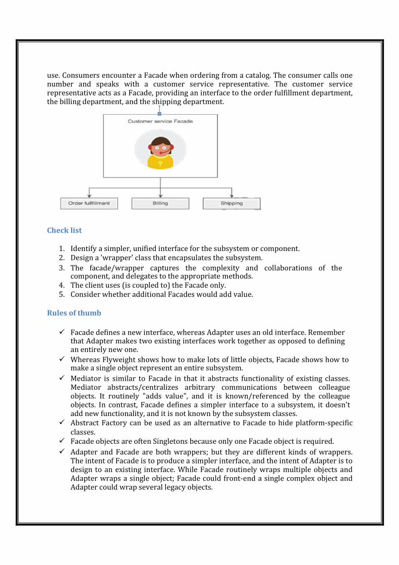
use. Consumers encounter a Facade when ordering from a catalog. The consumer calls one number and speaks with a customer service representative. The customer service representative acts as a Facade, providing an interface to the order fulfillment department, the billing department, and the shipping department.
Check list
1. Identify a simpler, unified interface for the subsystem or component.
2. Design a 'wrapper' class that encapsulates the subsystem. 3. The facade/wrapper captures the complexity and collaborations of the
component, and delegates to the appropriate methods. 4. The client uses (is coupled to) the Facade only.
5. Consider whether additional Facades would add value.
Rules of thumb
� Facade defines a new interface, whereas Adapter uses an old interface. Remember that Adapter makes two existing interfaces work together as opposed to defining an entirely new one.
� Whereas Flyweight shows how to make lots of little objects, Facade shows how to make a single object represent an entire subsystem.
� Mediator is similar to Facade in that it abstracts functionality of existing classes. Mediator abstracts/centralizes arbitrary communications between colleague objects. It routinely "adds value", and it is known/referenced by the colleague objects. In contrast, Facade defines a simpler interface to a subsystem, it doesn't add new functionality, and it is not known by the subsystem classes.
� Abstract Factory can be used as an alternative to Facade to hide platform-specific
classes.
� Facade objects are often Singletons because only one Facade object is required. � Adapter and Facade are both wrappers; but they are different kinds of wrappers.
The intent of Facade is to produce a simpler interface, and the intent of Adapter is to design to an existing interface. While Facade routinely wraps multiple objects and Adapter wraps a single object; Facade could front-end a single complex object and Adapter could wrap several legacy objects.
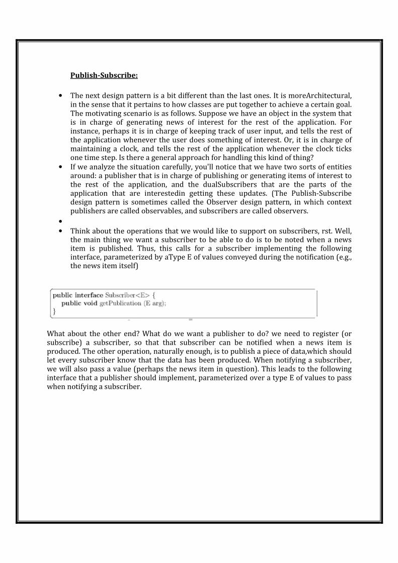
Publish-Subscribe:
• The next design pattern is a bit different than the last ones. It is moreArchitectural, in the sense that it pertains to how classes are put together to achieve a certain goal. The motivating scenario is as follows. Suppose we have an object in the system that is in charge of generating news of interest for the rest of the application. For instance, perhaps it is in charge of keeping track of user input, and tells the rest of the application whenever the user does something of interest. Or, it is in charge of maintaining a clock, and tells the rest of the application whenever the clock ticks one time step. Is there a general approach for handling this kind of thing?
• If we analyze the situation carefully, you'll notice that we have two sorts of entities around: a publisher that is in charge of publishing or generating items of interest to the rest of the application, and the dualSubscribers that are the parts of the application that are interestedin getting these updates. (The Publish-Subscribe design pattern is sometimes called the Observer design pattern, in which context publishers are called observables, and subscribers are called observers.
•
• Think about the operations that we would like to support on subscribers, rst. Well, the main thing we want a subscriber to be able to do is to be noted when a news item is published. Thus, this calls for a subscriber implementing the following interface, parameterized by aType E of values conveyed during the notification (e.g., the news item itself)
What about the other end? What do we want a publisher to do? we need to register (or subscribe) a subscriber, so that that subscriber can be notified when a news item is produced. The other operation, naturally enough, is to publish a piece of data,which should let every subscriber know that the data has been produced. When notifying a subscriber, we will also pass a value (perhaps the news item in question). This leads to the following interface that a publisher should implement, parameterized over a type E of values to pass when notifying a subscriber.
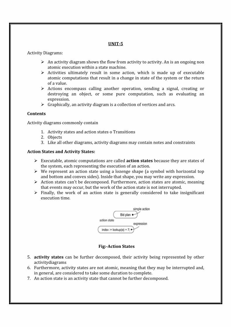
UNIT-5
Activity Diagrams:
� An activity diagram shows the flow from activity to activity. An is an ongoing non
atomic execution within a state machine.
� Activities ultimately result in some action, which is made up of executable
atomic computations that result in a change in state of the system or the return
of a value.
� Actions encompass calling another operation, sending a signal, creating or
destroying an object, or some pure computation, such as evaluating an
expression.
� Graphically, an activity diagram is a collection of vertices and arcs.
Contents
Activity diagrams commonly contain
1. Activity states and action states o Transitions
2. Objects
3. Like all other diagrams, activity diagrams may contain notes and constraints
Action States and Activity States:
� Executable, atomic computations are called action states because they are states of
the system, each representing the execution of an action.
� We represent an action state using a lozenge shape (a symbol with horizontal top
and bottom and convex sides). Inside that shape, you may write any expression.
� Action states can't be decomposed. Furthermore, action states are atomic, meaning
that events may occur, but the work of the action state is not interrupted.
� Finally, the work of an action state is generally considered to take insignificant
execution time.
Fig:-Action States
5. activity states can be further decomposed, their activity being represented by other
activitydiagrams
6. Furthermore, activity states are not atomic, meaning that they may be interrupted and,
in general, are considered to take some duration to complete.
7. An action state is an activity state that cannot be further decomposed.
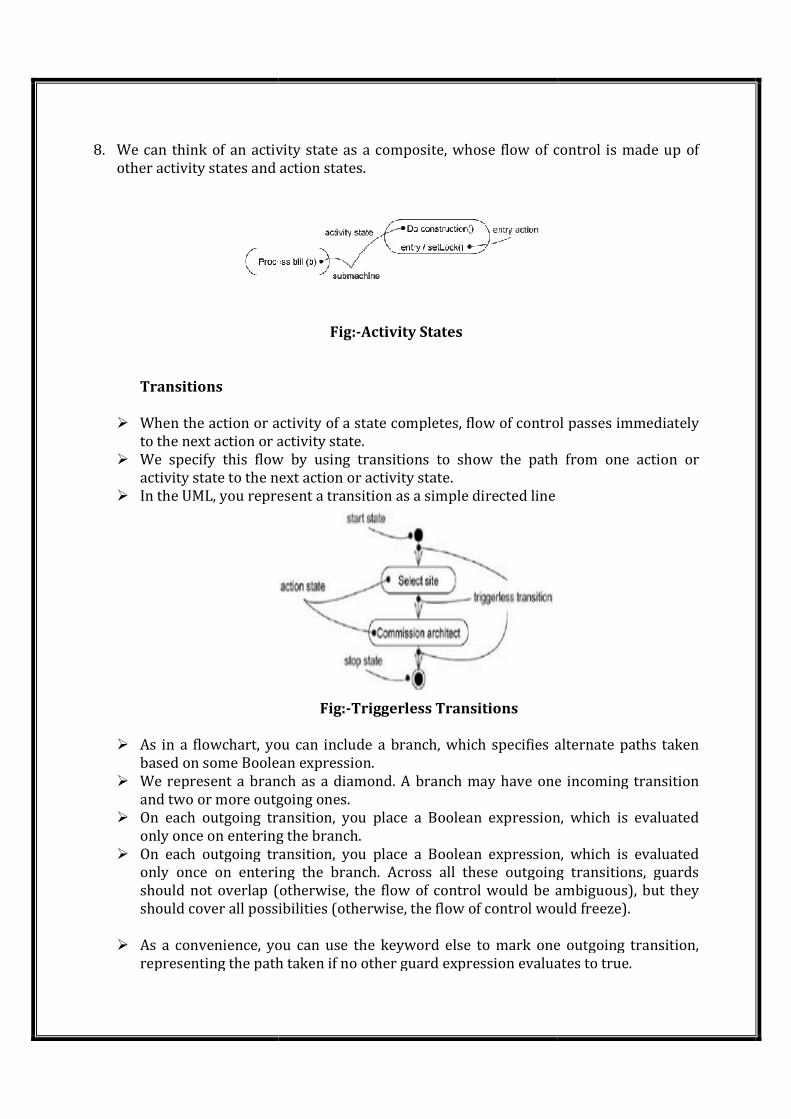
8. We can think of an activity state as a composite, whose flow of control is made up of
other activity states and action states.
Transitions
� When the action or activity of a state completes, flow of control passes immediately
to the next action or activity state.
� We specify this flow by using transitions to show the path from one action or
activity state to the next action or activity state.
� In the UML, you represent a transition as a simple directed line
Branching
� As in a flowchart, you can include a branch, which specifies alternate paths taken
based on some Boolean expression.
� We represent a branch as a
and two or more outgoing ones.
� On each outgoing transition, you place a Boolean expression, which is evaluated
only once on entering the branch.
� On each outgoing transition, you place a Boolean expression,
only once on entering the branch. Across all these outgoing transitions, guards
should not overlap (otherwise, the flow of control would be ambiguous), but they
should cover all possibilities (otherwise, the flow of control would freeze
� As a convenience, you can use the keyword else to mark one outgoing transition,
representing the path taken if no other guard expression evaluates to true.
We can think of an activity state as a composite, whose flow of control is made up of
other activity states and action states.
Fig:-Activity States
hen the action or activity of a state completes, flow of control passes immediately
to the next action or activity state.
We specify this flow by using transitions to show the path from one action or
activity state to the next action or activity state.
the UML, you represent a transition as a simple directed line
Fig:-Triggerless Transitions
As in a flowchart, you can include a branch, which specifies alternate paths taken
based on some Boolean expression.
We represent a branch as a diamond. A branch may have one incoming transition
and two or more outgoing ones.
On each outgoing transition, you place a Boolean expression, which is evaluated
only once on entering the branch.
On each outgoing transition, you place a Boolean expression,
only once on entering the branch. Across all these outgoing transitions, guards
should not overlap (otherwise, the flow of control would be ambiguous), but they
should cover all possibilities (otherwise, the flow of control would freeze
As a convenience, you can use the keyword else to mark one outgoing transition,
representing the path taken if no other guard expression evaluates to true.
We can think of an activity state as a composite, whose flow of control is made up of
hen the action or activity of a state completes, flow of control passes immediately
We specify this flow by using transitions to show the path from one action or
As in a flowchart, you can include a branch, which specifies alternate paths taken
diamond. A branch may have one incoming transition
On each outgoing transition, you place a Boolean expression, which is evaluated
On each outgoing transition, you place a Boolean expression, which is evaluated
only once on entering the branch. Across all these outgoing transitions, guards
should not overlap (otherwise, the flow of control would be ambiguous), but they
should cover all possibilities (otherwise, the flow of control would freeze).
As a convenience, you can use the keyword else to mark one outgoing transition,
representing the path taken if no other guard expression evaluates to true.
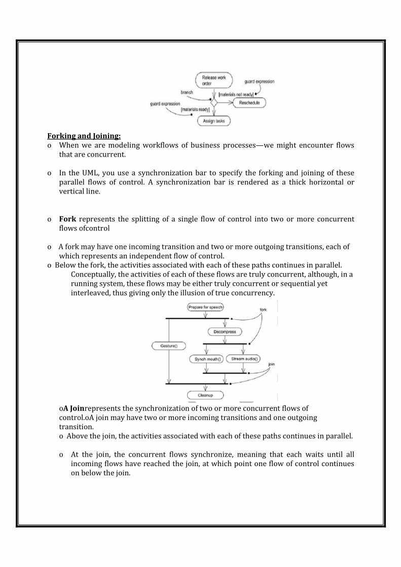
Forking and Joining:
o When we are modeling workflows of business processes—we might encounter flows
that are concurrent.
o In the UML, you use a synchronization bar to specify the forking and joining of these
parallel flows of control. A synchronization bar is rendered as a thick horizontal or
vertical line.
o Fork represents the splitting of a single flow of control into two or more concurrent
flows ofcontrol
o A fork may have one incoming transition and two or more outgoing transitions, each of
which represents an independent flow of control.
o Below the fork, the activities associated with each of these paths continues in parallel.
Conceptually, the activities of each of these flows are truly concurrent, although, in a
running system, these flows may be either truly concurrent or sequential yet
interleaved, thus giving only the illusion of true concurrency.
oA Joinrepresents the synchronization of two or more concurrent flows of
control.oA join may have two or more incoming transitions and one outgoing
transition.
o Above the join, the activities associated with each of these paths continues in parallel.
o At the join, the concurrent flows synchronize, meaning that each waits until all
incoming flows have reached the join, at which point one flow of control continues
on below the join.
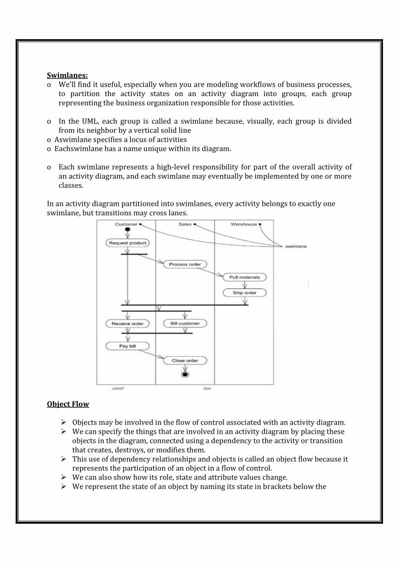
Swimlanes:
o We'll find it useful, especially when you are modeling workflows of business processes,
to partition the activity states on an activity diagram into groups, each group
representing the business organization responsible for those activities.
o In the UML, each group is called a swimlane because, visually, each group is divided
from its neighbor by a vertical solid line
o Aswimlane specifies a locus of activities
o Eachswimlane has a name unique within its diagram.
o Each swimlane represents a high-level responsibility for part of the overall activity of
an activity diagram, and each swimlane may eventually be implemented by one or more
classes.
In an activity diagram partitioned into swimlanes, every activity belongs to exactly one
swimlane, but transitions may cross lanes.
Object Flow
� Objects may be involved in the flow of control associated with an activity diagram.
� We can specify the things that are involved in an activity diagram by placing these
objects in the diagram, connected using a dependency to the activity or transition
that creates, destroys, or modifies them.
� This use of dependency relationships and objects is called an object flow because it
represents the participation of an object in a flow of control.
� We can also show how its role, state and attribute values change.
� We represent the state of an object by naming its state in brackets below the
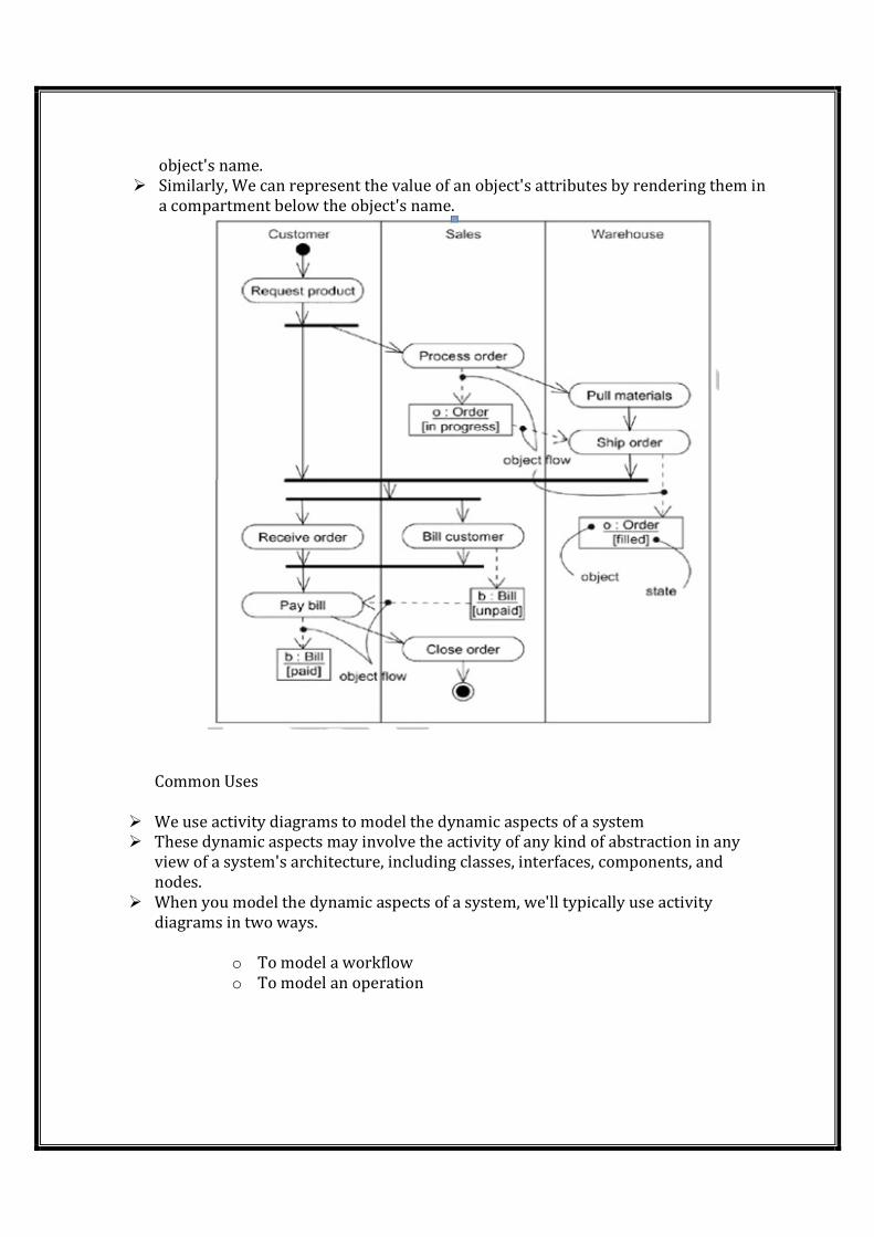
object's name.
� Similarly, We can represent the value of an object's attributes by rendering them in
a compartment below the object's name.
Common Uses
� We use activity diagrams to model the dynamic aspects of a system
� These dynamic aspects may involve the activity of any kind of abstraction in any
view of a system's architecture, including classes, interfaces, components, and
nodes.
� When you model the dynamic aspects of a system, we'll typically use activity
diagrams in two ways.
o To model a workflow
o To model an operation
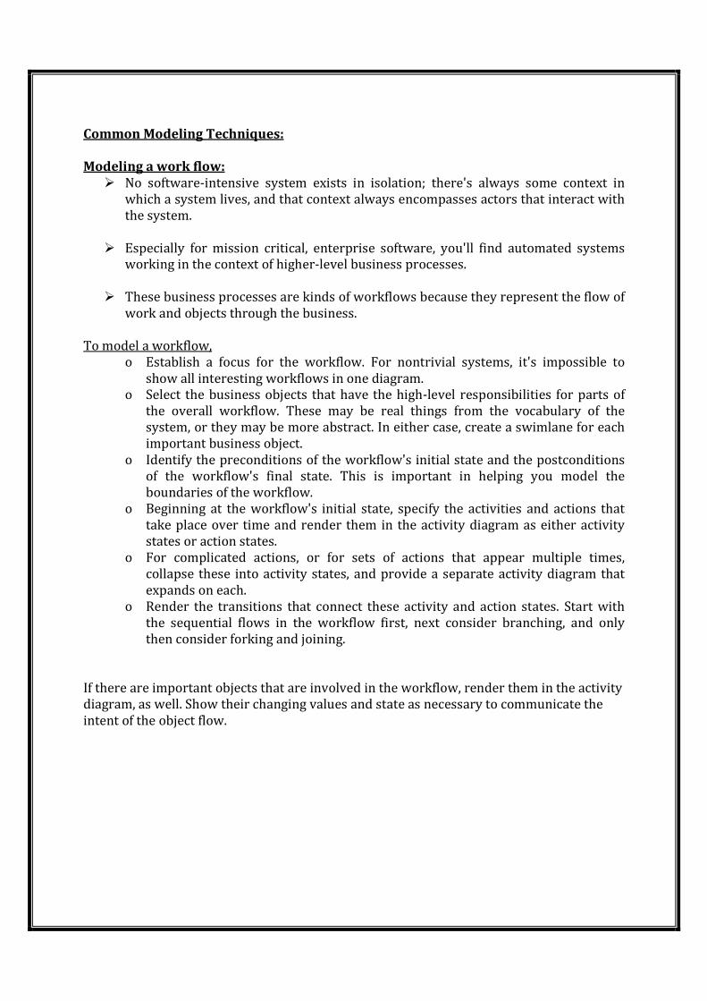
Common Modeling Techniques:
Modeling a work flow:
� No software-intensive system exists in isolation; there's always some context in
which a system lives, and that context always encompasses actors that interact with
the system.
� Especially for mission critical, enterprise software, you'll find automated systems
working in the context of higher-level business processes.
� These business processes are kinds of workflows because they represent the flow of
work and objects through the business.
To model a workflow,
o Establish a focus for the workflow. For nontrivial systems, it's impossible to
show all interesting workflows in one diagram.
o Select the business objects that have the high-level responsibilities for parts of
the overall workflow. These may be real things from the vocabulary of the
system, or they may be more abstract. In either case, create a swimlane for each
important business object.
o Identify the preconditions of the workflow's initial state and the postconditions
of the workflow's final state. This is important in helping you model the
boundaries of the workflow.
o Beginning at the workflow's initial state, specify the activities and actions that
take place over time and render them in the activity diagram as either activity
states or action states.
o For complicated actions, or for sets of actions that appear multiple times,
collapse these into activity states, and provide a separate activity diagram that
expands on each.
o Render the transitions that connect these activity and action states. Start with
the sequential flows in the workflow first, next consider branching, and only
then consider forking and joining.
If there are important objects that are involved in the workflow, render them in the activity
diagram, as well. Show their changing values and state as necessary to communicate the
intent of the object flow.
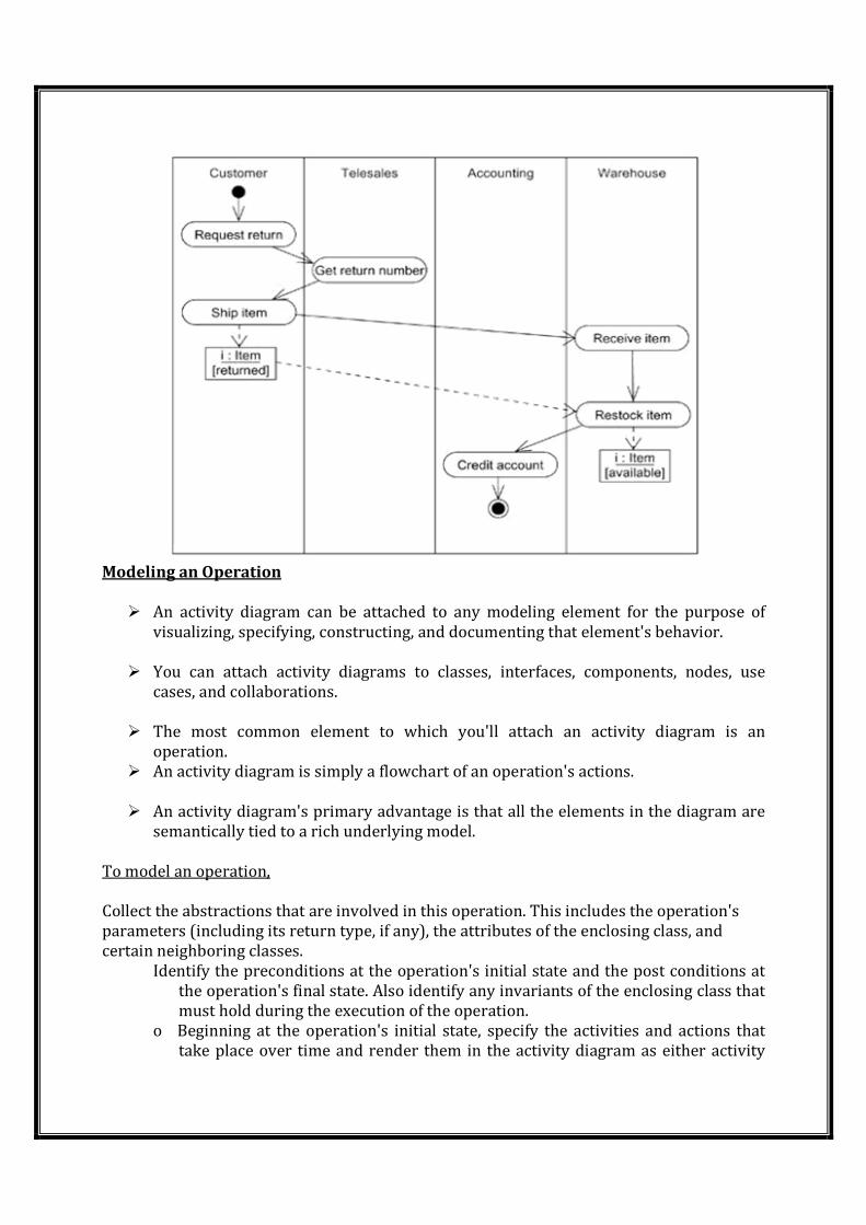
Modeling an Operation
� An activity diagram can be attached to any modeling element for the purpose of
visualizing, specifying, constructing, and documenting that element's behavior.
� You can attach activity diagrams to classes, interfaces, components, nodes, use
cases, and collaborations.
� The most common element to which you'll attach an activity diagram is an
operation.
� An activity diagram is simply a flowchart of an operation's actions.
� An activity diagram's primary advantage is that all the elements in the diagram are
semantically tied to a rich underlying model.
To model an operation,
Collect the abstractions that are involved in this operation. This includes the operation's
parameters (including its return type, if any), the attributes of the enclosing class, and
certain neighboring classes.
Identify the preconditions at the operation's initial state and the post conditions at
the operation's final state. Also identify any invariants of the enclosing class that
must hold during the execution of the operation.
o Beginning at the operation's initial state, specify the activities and actions that
take place over time and render them in the activity diagram as either activity
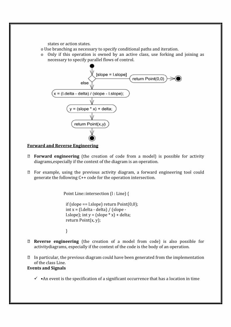
states or action states.
o Use branching as necessary to specify conditional paths and iteration.
o Only if this operation is owned by an active class, use forking and joining as
necessary to specify parallel flows of control.
Forward and Reverse Engineering
Forward engineering (the creation of code from a model) is possible for activity
diagrams,especially if the context of the diagram is an operation.
For example, using the previous activity diagram, a forward engineering tool could
generate the following C++ code for the operation intersection.
Point Line::intersection (l : Line) {
if (slope == l.slope) return Point(0,0);
int x = (l.delta - delta) / (slope -
l.slope); int y = (slope * x) + delta;
return Point(x, y);
}
Reverse engineering (the creation of a model from code) is also possible for
activitydiagrams, especially if the context of the code is the body of an operation.
In particular, the previous diagram could have been generated from the implementation
of the class Line.
Events and Signals
� •An event is the specification of a significant occurrence that has a location in time
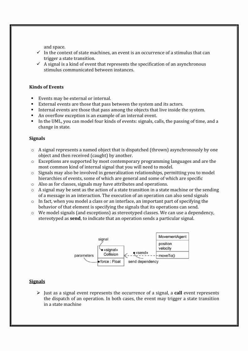
and space.
� In the context of state machines, an event is an occurrence of a stimulus that can
trigger a state transition.
� A signal is a kind of event that represents the specification of an asynchronous
stimulus communicated between instances.
Kinds of Events
� Events may be external or internal.
� External events are those that pass between the system and its actors.
� Internal events are those that pass among the objects that live inside the system.
� An overflow exception is an example of an internal event.
� In the UML, you can model four kinds of events: signals, calls, the passing of time, and a
change in state.
Signals
o A signal represents a named object that is dispatched (thrown) asynchronously by one
object and then received (caught) by another.
o Exceptions are supported by most contemporary programming languages and are the
most common kind of internal signal that you will need to model.
o Signals may also be involved in generalization relationships, permitting you to model
hierarchies of events, some of which are general and some of which are specific
o Also as for classes, signals may have attributes and operations.
o A signal may be sent as the action of a state transition in a state machine or the sending
of a message in an interaction. The execution of an operation can also send signals
o In fact, when you model a class or an interface, an important part of specifying the
behavior of that element is specifying the signals that its operations can send.
o We model signals (and exceptions) as stereotyped classes. We can use a dependency,
stereotyped as send, to indicate that an operation sends a particular signal.
Signals
Events
� Just as a signal event represents the occurrence of a signal, a call event represents
the dispatch of an operation. In both cases, the event may trigger a state transition
in a state machine
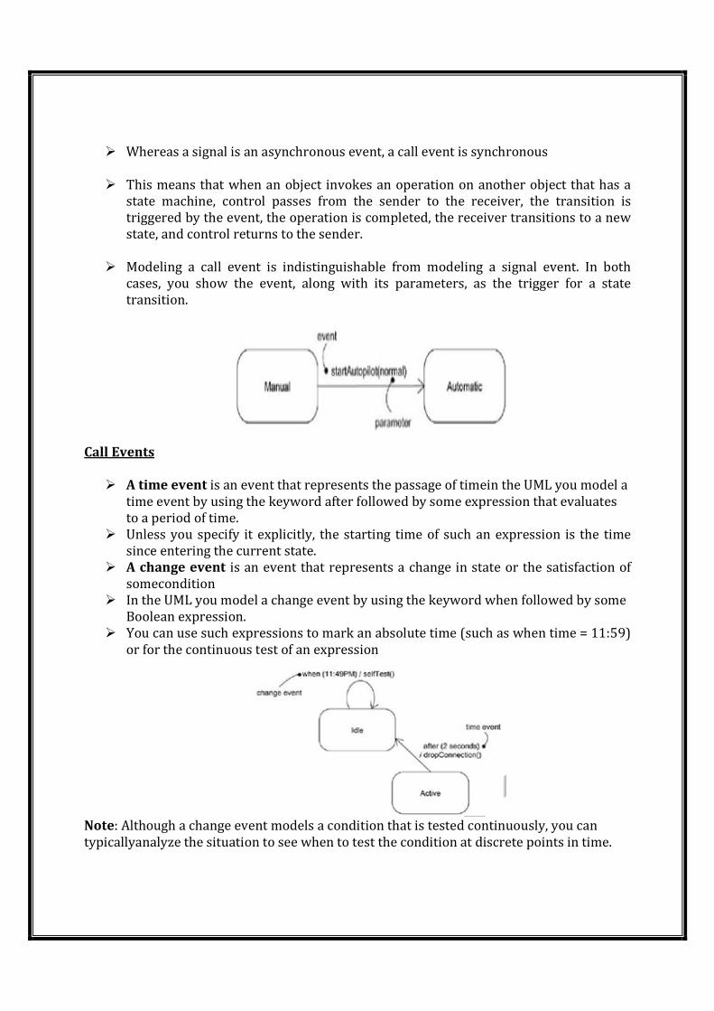
� Whereas a signal is an asynchronous event, a call event is synchronous
� This means that when an object invokes an operation on another object that has a
state machine, control passes from the sender to the receiver, the transition is
triggered by the event, the operation is completed, the receiver transitions to a new
state, and control returns to the sender.
� Modeling a call event is indistinguishable from modeling a signal event. In both
cases, you show the event, along with its parameters, as the trigger for a state
transition.
Call Events
� A time event is an event that represents the passage of timein the UML you model a
time event by using the keyword after followed by some expression that evaluates
to a period of time.
� Unless you specify it explicitly, the starting time of such an expression is the time
since entering the current state.
� A change event is an event that represents a change in state or the satisfaction of
somecondition
� In the UML you model a change event by using the keyword when followed by some
Boolean expression.
� You can use such expressions to mark an absolute time (such as when time = 11:59)
or for the continuous test of an expression
Note: Although a change event models a condition that is tested continuously, you can
typicallyanalyze the situation to see when to test the condition at discrete points in time.
Sending and Receiving Events
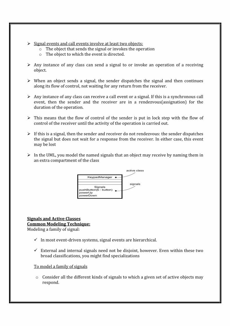
� Signal events and call events involve at least two objects:
o The object that sends the signal or invokes the operation
o The object to which the event is directed.
� Any instance of any class can send a signal to or invoke an operation of a receiving
object.
� When an object sends a signal, the sender dispatches the signal and then continues
along its flow of control, not waiting for any return from the receiver.
� Any instance of any class can receive a call event or a signal. If this is a synchronous call
event, then the sender and the receiver are in a rendezvous(assignation) for the
duration of the operation.
� This means that the flow of control of the sender is put in lock step with the flow of
control of the receiver until the activity of the operation is carried out.
� If this is a signal, then the sender and receiver do not rendezvous: the sender dispatches
the signal but does not wait for a response from the receiver. In either case, this event
may be lost
� In the UML, you model the named signals that an object may receive by naming them in
an extra compartment of the class
Signals and Active Classes
Common Modeling Technique:
Modeling a family of signal:
� In most event-driven systems, signal events are hierarchical.
� External and internal signals need not be disjoint, however. Even within these two
broad classifications, you might find specializations
To model a family of signals
o Consider all the different kinds of signals to which a given set of active objects may
respond.
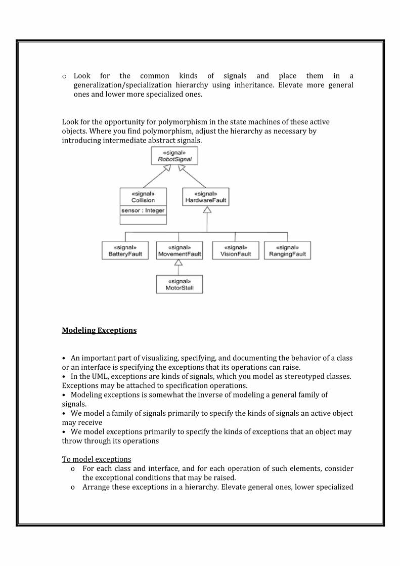
o Look for the common kinds of signals and place them in a
generalization/specialization hierarchy using inheritance. Elevate more general
ones and lower more specialized ones.
Look for the opportunity for polymorphism in the state machines of these active
objects. Where you find polymorphism, adjust the hierarchy as necessary by
introducing intermediate abstract signals.
Modeling Exceptions
• An important part of visualizing, specifying, and documenting the behavior of a class
or an interface is specifying the exceptions that its operations can raise.
• In the UML, exceptions are kinds of signals, which you model as stereotyped classes.
Exceptions may be attached to specification operations.
• Modeling exceptions is somewhat the inverse of modeling a general family of
signals.
• We model a family of signals primarily to specify the kinds of signals an active object
may receive
• We model exceptions primarily to specify the kinds of exceptions that an object may
throw through its operations
To model exceptions
o For each class and interface, and for each operation of such elements, consider
the exceptional conditions that may be raised.
o Arrange these exceptions in a hierarchy. Elevate general ones, lower specialized
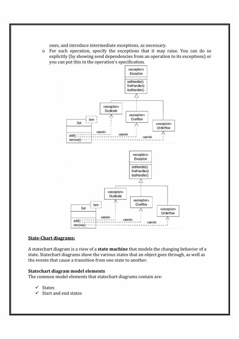
ones, and introduce intermediate exceptions, as necessary.
o For each operation, specify the exceptions that it may raise. You can do so
explicitly (by showing send dependencies from an operation to its exceptions) or
you can put this in the operation's specification.
State-Chart diagrams:
A statechart diagram is a view of a state machine that models the changing behavior of a
state. Statechart diagrams show the various states that an object goes through, as well as
the events that cause a transition from one state to another.
Statechart diagram model elements
The common model elements that statechart diagrams contain are:
� States
� Start and end states
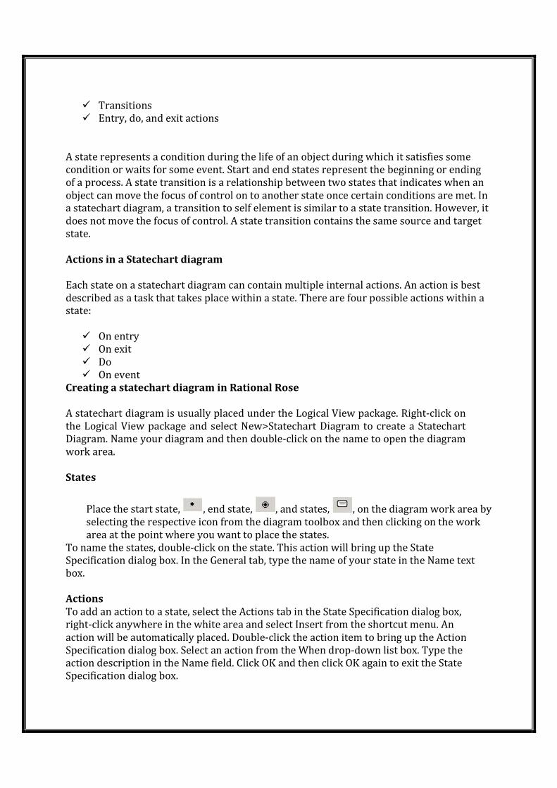
� Transitions
� Entry, do, and exit actions
A state represents a condition during the life of an object during which it satisfies some
condition or waits for some event. Start and end states represent the beginning or ending
of a process. A state transition is a relationship between two states that indicates when an
object can move the focus of control on to another state once certain conditions are met. In
a statechart diagram, a transition to self element is similar to a state transition. However, it
does not move the focus of control. A state transition contains the same source and target
state.
Actions in a Statechart diagram
Each state on a statechart diagram can contain multiple internal actions. An action is best
described as a task that takes place within a state. There are four possible actions within a
state:
� On entry
� On exit
� Do
� On event
Creating a statechart diagram in Rational Rose
A statechart diagram is usually placed under the Logical View package. Right-click on
the Logical View package and select New>Statechart Diagram to create a Statechart
Diagram. Name your diagram and then double-click on the name to open the diagram
work area.
States
Place the start state, , end state, , and states, , on the diagram work area by
selecting the respective icon from the diagram toolbox and then clicking on the work
area at the point where you want to place the states.
To name the states, double-click on the state. This action will bring up the State
Specification dialog box. In the General tab, type the name of your state in the Name text
box.
Actions
To add an action to a state, select the Actions tab in the State Specification dialog box,
right-click anywhere in the white area and select Insert from the shortcut menu. An
action will be automatically placed. Double-click the action item to bring up the Action
Specification dialog box. Select an action from the When drop-down list box. Type the
action description in the Name field. Click OK and then click OK again to exit the State
Specification dialog box.
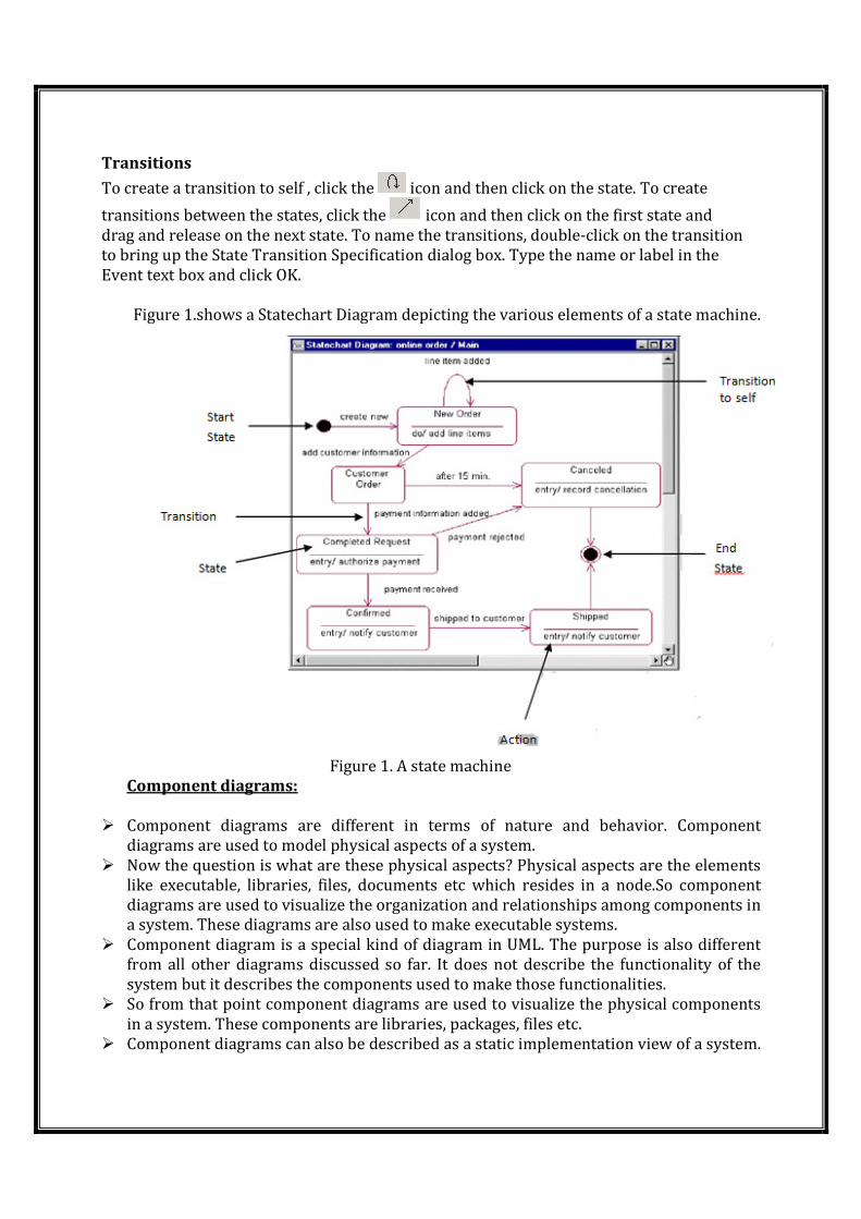
Transitions
To create a transition to self , click the icon and then click on the state. To create
transitions between the states, click the icon and then click on the first state and
drag and release on the next state. To name the transitions, double-click on the transition
to bring up the State Transition Specification dialog box. Type the name or label in the
Event text box and click OK.
Figure 1.shows a Statechart Diagram depicting the various elements of a state machine.
Figure 1. A state machine
Component diagrams:
� Component diagrams are different in terms of nature and behavior. Component
diagrams are used to model physical aspects of a system.
� Now the question is what are these physical aspects? Physical aspects are the elements
like executable, libraries, files, documents etc which resides in a node.So component
diagrams are used to visualize the organization and relationships among components in
a system. These diagrams are also used to make executable systems.
� Component diagram is a special kind of diagram in UML. The purpose is also different
from all other diagrams discussed so far. It does not describe the functionality of the
system but it describes the components used to make those functionalities.
� So from that point component diagrams are used to visualize the physical components
in a system. These components are libraries, packages, files etc.
� Component diagrams can also be described as a static implementation view of a system.
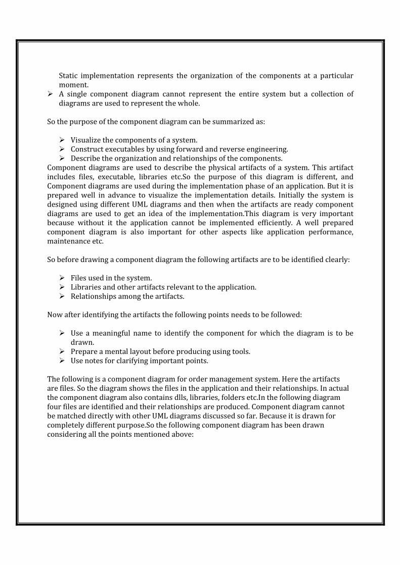
Static implementation represents the organization of the components at a particular
moment.
� A single component diagram cannot represent the entire system but a collection of
diagrams are used to represent the whole.
So the purpose of the component diagram can be summarized as:
� Visualize the components of a system.
� Construct executables by using forward and reverse engineering.
� Describe the organization and relationships of the components.
Component diagrams are used to describe the physical artifacts of a system. This artifact
includes files, executable, libraries etc.So the purpose of this diagram is different, and
Component diagrams are used during the implementation phase of an application. But it is
prepared well in advance to visualize the implementation details. Initially the system is
designed using different UML diagrams and then when the artifacts are ready component
diagrams are used to get an idea of the implementation.This diagram is very important
because without it the application cannot be implemented efficiently. A well prepared
component diagram is also important for other aspects like application performance,
maintenance etc.
So before drawing a component diagram the following artifacts are to be identified clearly:
� Files used in the system.
� Libraries and other artifacts relevant to the application.
� Relationships among the artifacts.
Now after identifying the artifacts the following points needs to be followed:
� Use a meaningful name to identify the component for which the diagram is to be
drawn.
� Prepare a mental layout before producing using tools.
� Use notes for clarifying important points.
The following is a component diagram for order management system. Here the artifacts
are files. So the diagram shows the files in the application and their relationships. In actual
the component diagram also contains dlls, libraries, folders etc.In the following diagram
four files are identified and their relationships are produced. Component diagram cannot
be matched directly with other UML diagrams discussed so far. Because it is drawn for
completely different purpose.So the following component diagram has been drawn
considering all the points mentioned above:
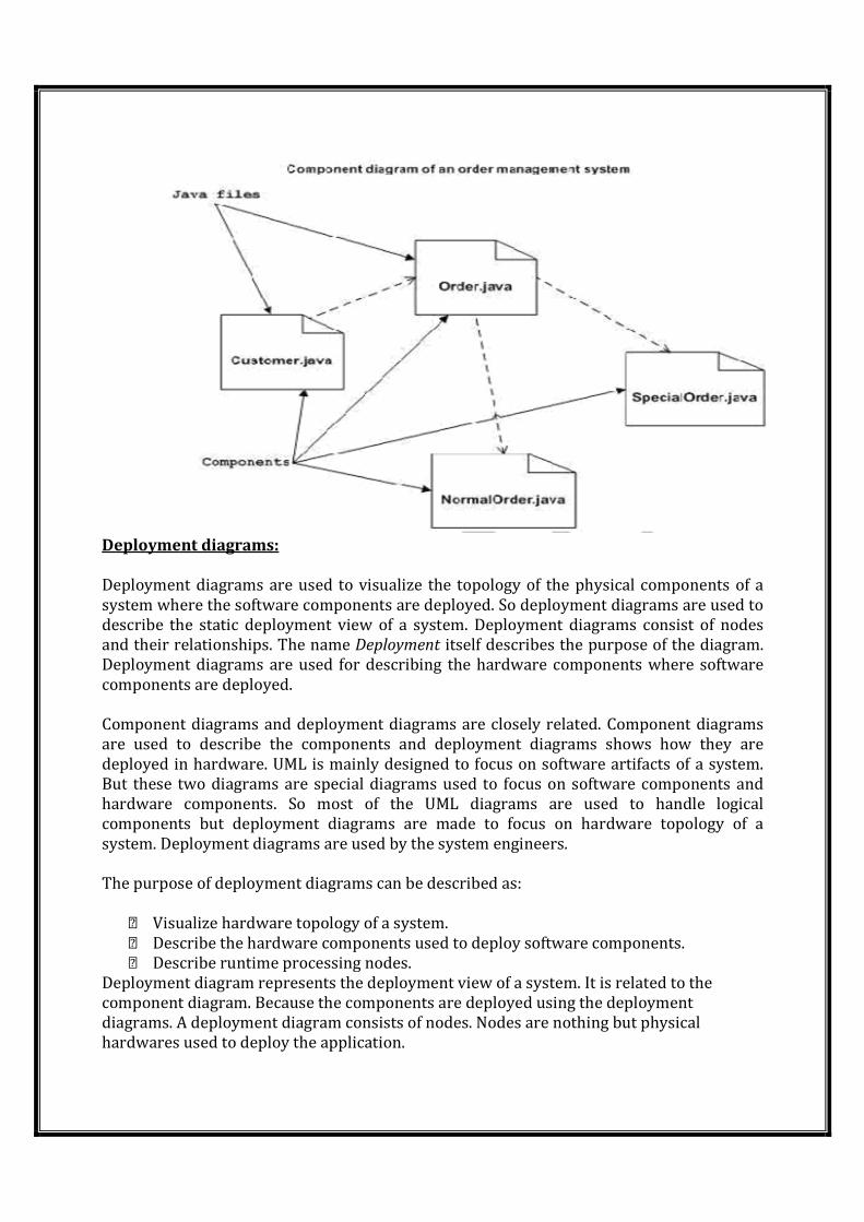
Deployment diagrams:
Deployment diagrams are used to visualize the topology of the physical components of a
system where the software components are deployed. So deployment diagrams are used to
describe the static deployment view of a system. Deployment diagrams consist of nodes
and their relationships. The name Deployment itself describes the purpose of the diagram.
Deployment diagrams are used for describing the hardware components where software
components are deployed.
Component diagrams and deployment diagrams are closely related. Component diagrams
are used to describe the components and deployment diagrams shows how they are
deployed in hardware. UML is mainly designed to focus on software artifacts of a system.
But these two diagrams are special diagrams used to focus on software components and
hardware components. So most of the UML diagrams are used to handle logical
components but deployment diagrams are made to focus on hardware topology of a
system. Deployment diagrams are used by the system engineers.
The purpose of deployment diagrams can be described as:
Visualize hardware topology of a system.
Describe the hardware components used to deploy software components.
Describe runtime processing nodes.
Deployment diagram represents the deployment view of a system. It is related to the
component diagram. Because the components are deployed using the deployment
diagrams. A deployment diagram consists of nodes. Nodes are nothing but physical
hardwares used to deploy the application.
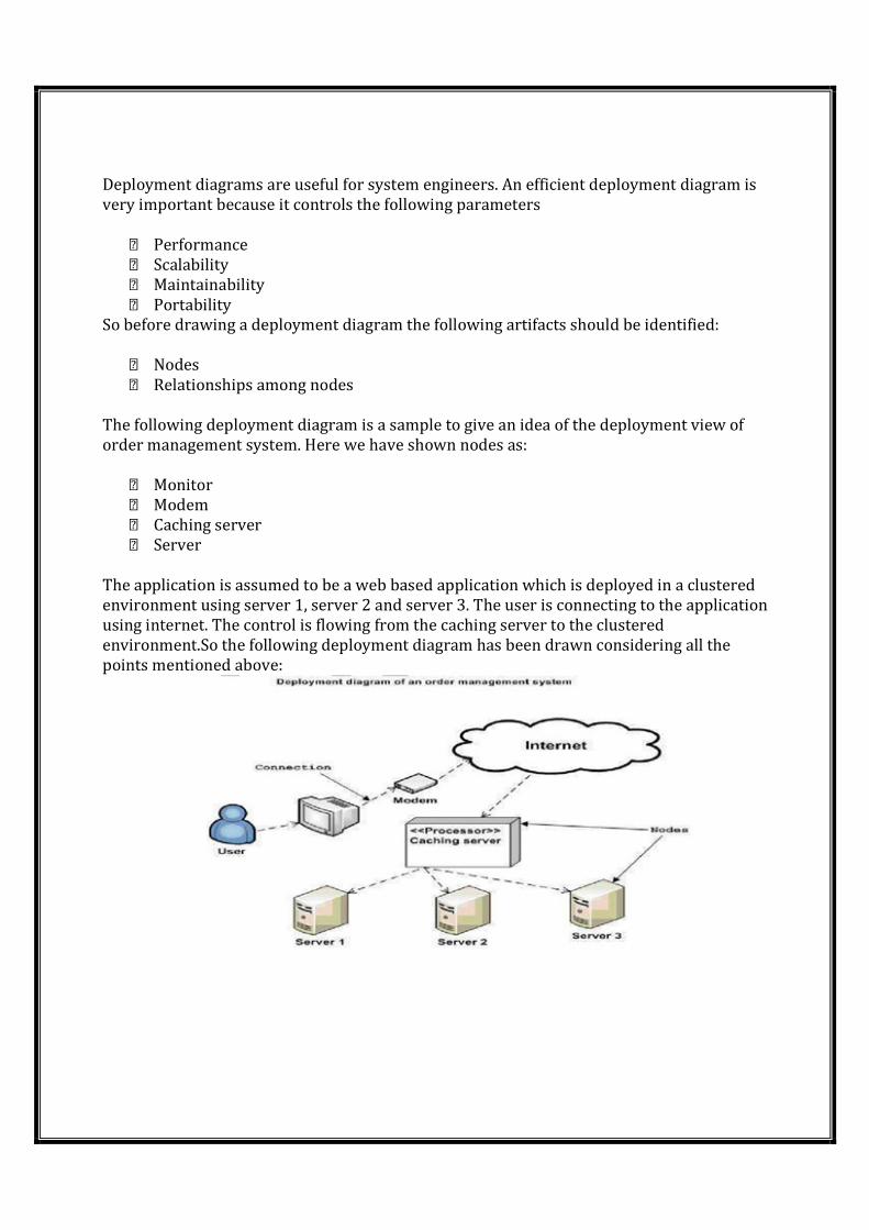
Deployment diagrams are useful for system engineers. An efficient deployment diagram is
very important because it controls the following parameters
Performance
Scalability
Maintainability
Portability
So before drawing a deployment diagram the following artifacts should be identified:
Nodes
Relationships among nodes
The following deployment diagram is a sample to give an idea of the deployment view of
order management system. Here we have shown nodes as:
Monitor
Modem
Caching server
Server
The application is assumed to be a web based application which is deployed in a clustered
environment using server 1, server 2 and server 3. The user is connecting to the application
using internet. The control is flowing from the caching server to the clustered
environment.So the following deployment diagram has been drawn considering all the
points mentioned above:
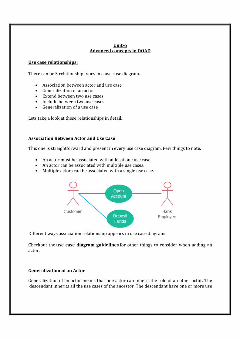
Unit-6
Advanced concepts in OOAD
Use case relationships:
There can be 5 relationship types in a use case diagram.
• Association between actor and use case
• Generalization of an actor
• Extend between two use cases
• Include between two use cases
• Generalization of a use case
Lets take a look at these relationships in detail.
Association Between Actor and Use Case
This one is straightforward and present in every use case diagram. Few things to note.
• An actor must be associated with at least one use case.
• An actor can be associated with multiple use cases. • Multiple actors can be associated with a single use case.
Different ways association relationship appears in use case diagrams
Checkout the use case diagram guidelines for other things to consider when adding an
actor.
Generalization of an Actor
Generalization of an actor means that one actor can inherit the role of an other actor. The
descendant inherits all the use cases of the ancestor. The descendant have one or more use
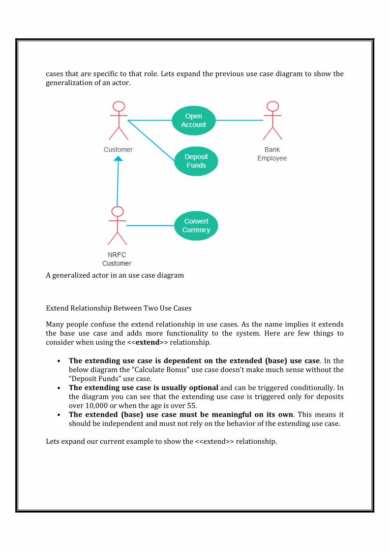
cases that are specific to that role. Lets expand the previous use case diagram to show the
generalization of an actor.
A generalized actor in an use case diagram
Extend Relationship Between Two Use Cases
Many people confuse the extend relationship in use cases. As the name implies it extends
the base use case and adds more functionality to the system. Here are few things to
consider when using the <<extend>> relationship.
• The extending use case is dependent on the extended (base) use case. In the
below diagram the “Calculate Bonus” use case doesn’t make much sense without the
“Deposit Funds” use case.
• The extending use case is usually optional and can be triggered conditionally. In
the diagram you can see that the extending use case is triggered only for deposits
over 10,000 or when the age is over 55.
• The extended (base) use case must be meaningful on its own. This means it
should be independent and must not rely on the behavior of the extending use case.
Lets expand our current example to show the <<extend>> relationship.
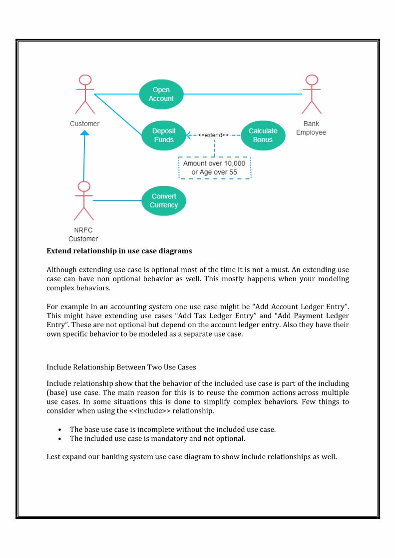
Extend relationship in use case diagrams
Although extending use case is optional most of the time it is not a must. An extending use
case can have non optional behavior as well. This mostly happens when your modeling
complex behaviors.
For example in an accounting system one use case might be “Add Account Ledger Entry”.
This might have extending use cases “Add Tax Ledger Entry” and “Add Payment Ledger
Entry”. These are not optional but depend on the account ledger entry. Also they have their
own specific behavior to be modeled as a separate use case.
Include Relationship Between Two Use Cases
Include relationship show that the behavior of the included use case is part of the including
(base) use case. The main reason for this is to reuse the common actions across multiple
use cases. In some situations this is done to simplify complex behaviors. Few things to
consider when using the <<include>> relationship.
• The base use case is incomplete without the included use case.
• The included use case is mandatory and not optional.
Lest expand our banking system use case diagram to show include relationships as well.
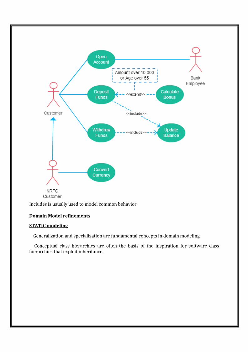
Includes is usually used to model common behavior
Domain Model refinements
STATIC modeling
� Generalization and specialization are fundamental concepts in domain modeling.
� Conceptual class hierarchies are often the basis of the inspiration for software class
hierarchies that exploit inheritance.
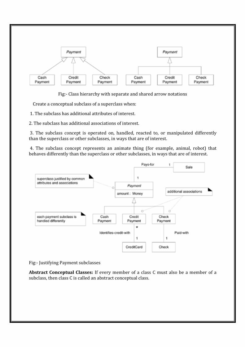
Fig:- Class hierarchy with separate and shared arrow notations
� Create a conceptual subclass of a superclass when:
1. The subclass has additional attributes of interest.
2. The subclass has additional associations of interest.
3. The subclass concept is operated on, handled, reacted to, or manipulated differently
than the superclass or other subclasses, in ways that are of interest.
4. The subclass concept represents an animate thing (for example, animal, robot) that
behaves differently than the superclass or other subclasses, in ways that are of interest.
Fig:- Justifying Payment subclasses
Abstract Conceptual Classes: If every member of a class C must also be a member of a
subclass, then class C is called an abstract conceptual class.
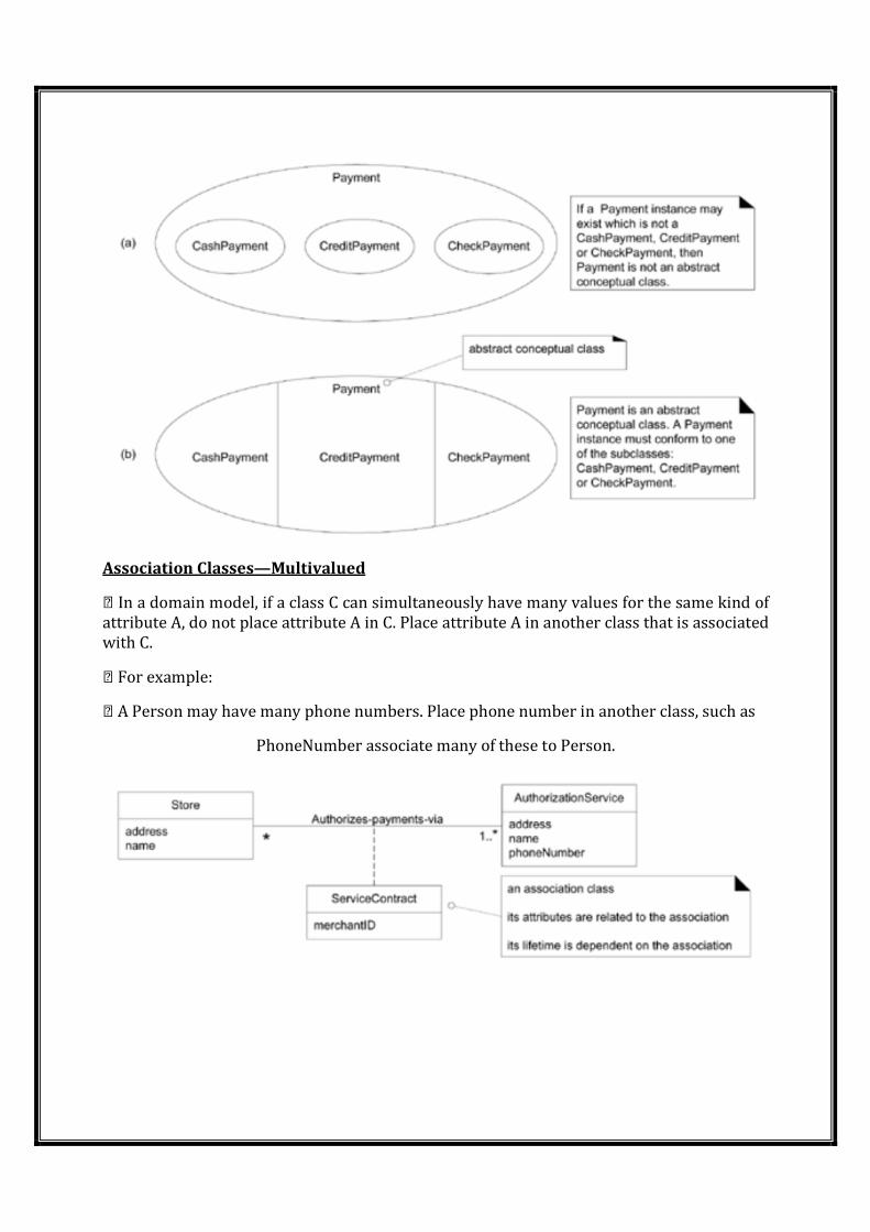
Association Classes—Multivalued
In a domain model, if a class C can simultaneously have many values for the same kind of
attribute A, do not place attribute A in C. Place attribute A in another class that is associated
with C.
For example:
A Person may have many phone numbers. Place phone number in another class, such as
PhoneNumber associate many of these to Person.
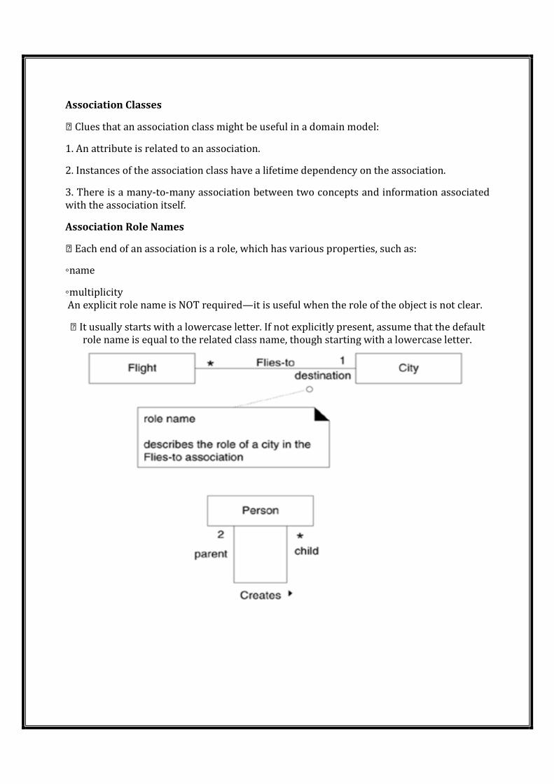
Association Classes
Clues that an association class might be useful in a domain model:
1. An attribute is related to an association.
2. Instances of the association class have a lifetime dependency on the association.
3. There is a many-to-many association between two concepts and information associated
with the association itself.
Association Role Names
Each end of an association is a role, which has various properties, such as:
◦name
◦multiplicity
An explicit role name is NOT required—it is useful when the role of the object is not clear.
It usually starts with a lowercase letter. If not explicitly present, assume that the default
role name is equal to the related class name, though starting with a lowercase letter.
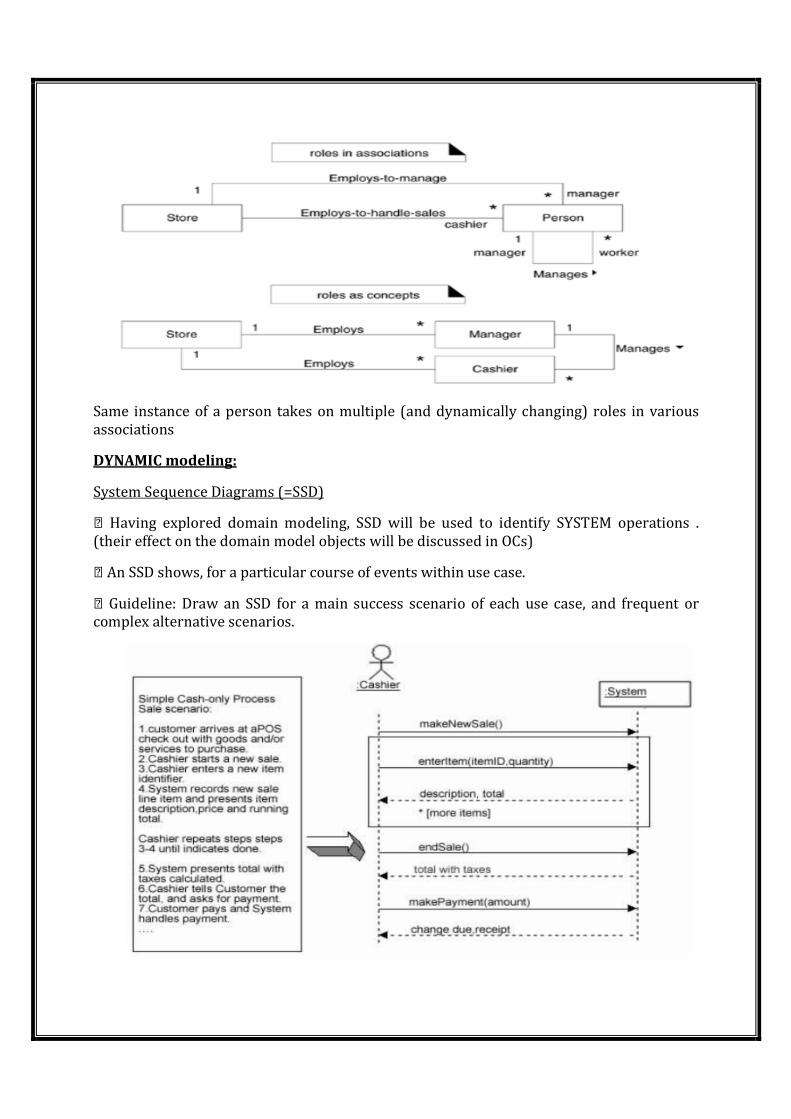
Same instance of a person takes on multiple (and dynamically changing) roles in various
associations
DYNAMIC modeling:
System Sequence Diagrams (=SSD)
Having explored domain modeling, SSD will be used to identify SYSTEM operations .
(their effect on the domain model objects will be discussed in OCs)
An SSD shows, for a particular course of events within use case.
Guideline: Draw an SSD for a main success scenario of each use case, and frequent or
complex alternative scenarios.
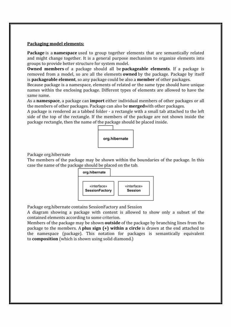
Packaging model elements:
Package is a namespace used to group together elements that are semantically related
and might change together. It is a general purpose mechanism to organize elements into
groups to provide better structure for system model.
Owned members of a package should all be packageable elements. If a package is
removed from a model, so are all the elements owned by the package. Package by itself
is packageable element, so any package could be also a member of other packages.
Because package is a namespace, elements of related or the same type should have unique
names within the enclosing package. Different types of elements are allowed to have the
same name.
As a namespace, a package can import either individual members of other packages or all
the members of other packages. Package can also be mergedwith other packages.
A package is rendered as a tabbed folder - a rectangle with a small tab attached to the left
side of the top of the rectangle. If the members of the package are not shown inside the
package rectangle, then the name of the package should be placed inside.
Package org.hibernate
The members of the package may be shown within the boundaries of the package. In this
case the name of the package should be placed on the tab.
Package org.hibernate contains SessionFactory and Session
A diagram showing a package with content is allowed to show only a subset of the
contained elements according to some criterion.
Members of the package may be shown outside of the package by branching lines from the
package to the members. A plus sign (+) within a circle is drawn at the end attached to
the namespace (package). This notation for packages is semantically equivalent
to composition (which is shown using solid diamond.)
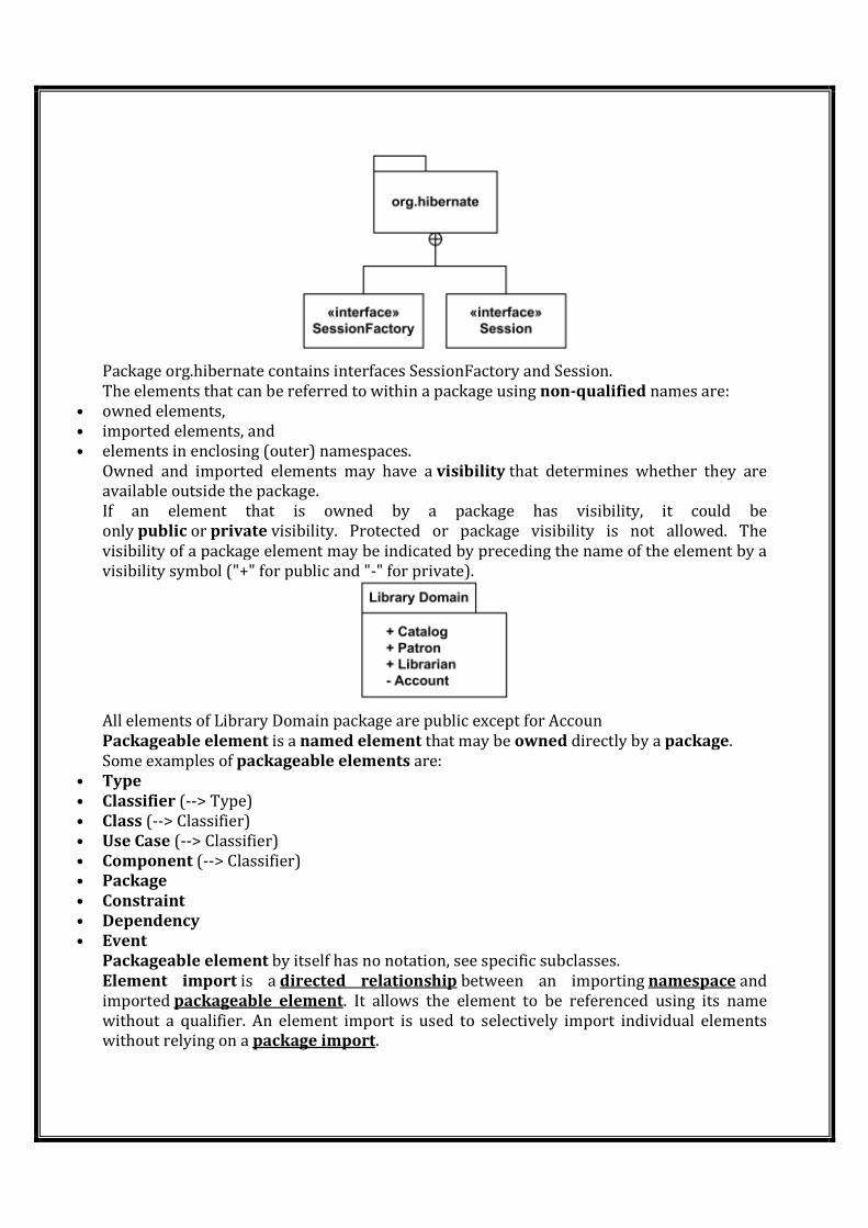
Package org.hibernate contains interfaces SessionFactory and Session.
The elements that can be referred to within a package using non-qualified names are:
• owned elements,
• imported elements, and
• elements in enclosing (outer) namespaces.
Owned and imported elements may have a visibility that determines whether they are
available outside the package.
If an element that is owned by a package has visibility, it could be
only public or private visibility. Protected or package visibility is not allowed. The
visibility of a package element may be indicated by preceding the name of the element by a
visibility symbol ("+" for public and "-" for private).
All elements of Library Domain package are public except for Accoun
Packageable element is a named element that may be owned directly by a package.
Some examples of packageable elements are:
• Type
• Classifier (--> Type)
• Class (--> Classifier)
• Use Case (--> Classifier)
• Component (--> Classifier)
• Package
• Constraint
• Dependency
• Event
Packageable element by itself has no notation, see specific subclasses.
Element import is a directed relationship between an importing namespace and
imported packageable element. It allows the element to be referenced using its name
without a qualifier. An element import is used to selectively import individual elements
without relying on a package import.
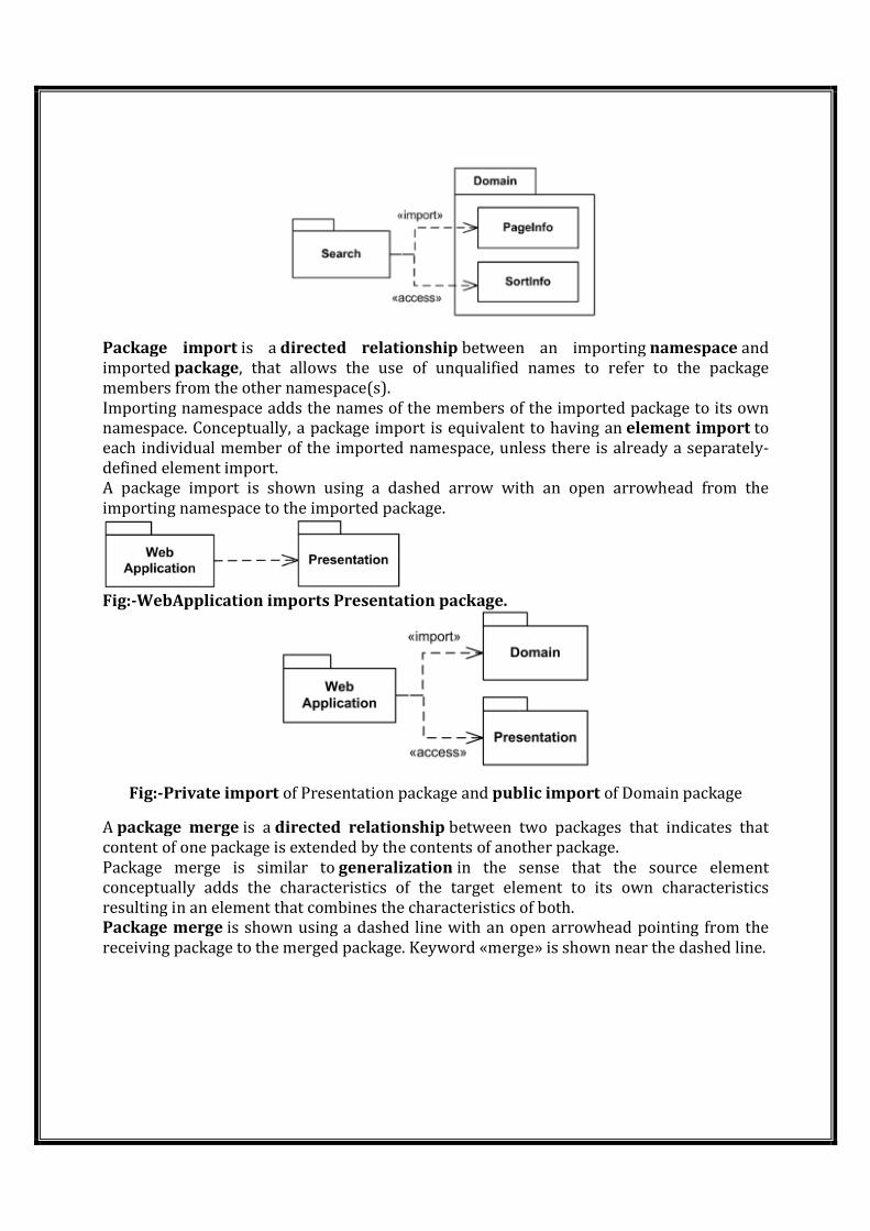
Package import is a directed relationship between an importing namespace and
imported package, that allows the use of unqualified names to refer to the package
members from the other namespace(s).
Importing namespace adds the names of the members of the imported package to its own
namespace. Conceptually, a package import is equivalent to having an element import to
each individual member of the imported namespace, unless there is already a separately-
defined element import.
A package import is shown using a dashed arrow with an open arrowhead from the
importing namespace to the imported package.
Fig:-WebApplication imports Presentation package.
Fig:-Private import of Presentation package and public import of Domain package
A package merge is a directed relationship between two packages that indicates that
content of one package is extended by the contents of another package.
Package merge is similar to generalization in the sense that the source element
conceptually adds the characteristics of the target element to its own characteristics
resulting in an element that combines the characteristics of both.
Package merge is shown using a dashed line with an open arrowhead pointing from the
receiving package to the merged package. Keyword «merge» is shown near the dashed line.