Embed Size (px)
Citation preview

RATIONAL ROSERATIONAL ROSE
RAT IONAL ROSE SOFTWA RE
A N A L Y S I S A N D D E S I G NThe application’s method recommends the use of static and dynamic views of a logical model and a physical model to capture the in-process products of object-oriented analysis and design. Using the notation, the application enables you to create and refine these views within an overall model representing your problem domain and software system.This overall model contains classes, use cases, objects, packages, operations, component packages, components, processors, devices and the relationships between them. Each of these model elements possesses model properties that identify and characterize them. The notation provides graphical icons to represent each kind of model element and relationship.
A model also contains diagrams and specifications, which provide a means of visualizing and manipulating the model’s elements and their model properties. Since diagrams are used to illustrate multiple views of a model, icons representing a model element can appear in none, one, or several of a model’s diagrams. The application therefore enables you to control, which element, relationship, and property icons appear on each diagram, using facilities provided by its application window. Within its application window, it displays each diagram in a diagram window, and each specification in a specification window.
USE CASE VIEW• Contains the use case models, flow of events and supplementary documentation.• It is a contract between customer and developer.• It is essential for analysis, design and test activities.• It also contains activity diagrams.• It contains the use case diagrams.• It is the heart of the other views that represent the required behaviour of the system.
LOGICAL VIEW• It supports the functional requirements of the system.• It includes the use case realization, class diagram, interaction diagram, state chart and
activity diagram.
PROCESS VIEW• It addresses the performance, scalability and throughput of the system.• It includes the threads and the processes that found the system concurrency and
synchronization mechanism.• It is not necessary for single processing environment.
1

COMPONENT VIEW• The component view addresses the ease of development management of software
assets, reuse, subcontracting and of the shelf components.• Describes the organization of static software, like source call data files components in
terms of packaging, layering and configuration management.
DEPLOYMENT VIEW• It addresses the issue like deployment installation and performance.• The deployment view is used for distributed systems only.• It shows the various executables like a runtime components and computing modes.• It contains deployment diagrams.
2

3

4

EX.NO: DATE: ATM SYSTEMATM SYSTEM
A IM :To analyze, design and develop code for Automated Teller Machine system using Rational
Rose software.
PROJECT SCOPE :The main scope of the project is to perform the transactions and to update our account
balance using ATM machine systems.
OBJECT IVE :The main objective of designing and implementing an ATM system is to enable the customer
to have the easy transaction of money at any time without standing or waiting in the queue.
INFRASTRUCTURE :
H A R D W A R E R E Q U I R E M E N T S• Processor: x86-based processor.• Hard disk: 20 GB (min)• RAM: 128 MB (min)
S O F T W A R E R E Q U I R E M E N T S• Rational Rose Enterprise edition• Visual Basic 6.0
5

6

A BSTRACT :ATM stands for Automatic Teller Machine. It is nothing but immediate aspect of getting
money by using simple card.User can simply insert ATM card into the ATM machine and follow the simple instructions
provided by the machine to get the required amount of money from his/her own account. To protect their account from other users to access, password is provided which is called as pin number and is provided uniquely for each user. ATM machines acts as an excellent technical development that provides money for those users who required money at whatever time they required.
Various concepts that are taken care are• Pin number validation• Money withdrawal• Account viewing
PROBLEM STATEMENT :The ATM system provides us to withdraw cash instantly from any ATM machine belonging to a
particular network. All the transactions made through ATMs are without human intervention and the account of the customer is updated immediately. This ensures enhanced customer service and hassle free account maintenance.
7

MOD ULA R DESCR IPT ION
V E R I F I C A T I O N O F A T M C A R DFor the verification of ATM card by the system, the user will enter the secret code.
The pin number or code number is verified with the database of the customers. If the code exactly is matched with database of that of the customers then transaction can be performed. If the code does not match with the database of the customer then the user is requested again to re-enter the pin number of the access card and is continued further.
T R A N S A C T I O NIn this module, the necessary transaction to be performed by the user is displayed as
option by the system. The transaction options are withdrawal, deposit, balance enquiry, mini statement, pin change. The users can withdraw the amount from their account if the amount is available in their account. The users can also deposit the amount in their account either by cash or cheque. This module helps the users to check their balance in their account through balance enquiry and also they can get the mini statement for recent transaction done over their account. This module allows the users to change their pin number if they need.
D I S P L A Y A N D R E C E I P TIn this module, after the user performs the transaction process the system displays the
balance amount available in the account and the amount withdrawn by the user through receipt. The receipt will be provided at the end of the transaction process.
8

9

USE CASE D IAGRAM
D E S C R I P T I O N :
Use-case diagrams graphically depict system behavior (use cases). These diagrams present a high level view of how the system is used as viewed from an outsider’s (actor’s) perspective.
10
CLASS D IAGRAM
D E S C R I P T I O N :
The class diagram shows a set of classes, interfaces and collaboration and their relationship. They are used for constructing executable system through forward and reverse engineering. Class diagram shows the attributes and operation of a class and constraints that apply to the way the object are connected.
11

SEQUENCE D IAGRAM
D E S C R I P T I O N :
A sequence diagram is a graphical view of a scenario that shows object interaction in a time-based sequence – what happens first, what happens next. Sequence diagrams establish the roles of objects and help provide essential information to determine class responsibilities and interfaces.
12

COLLA BORAT ION D IAGRAM
D E S C R I P T I O N :
The collaboration diagram can be drawn from the sequential diagram by means of pressing F5. The collaboration diagram shows the overall flow of central towards each phase of the class
13
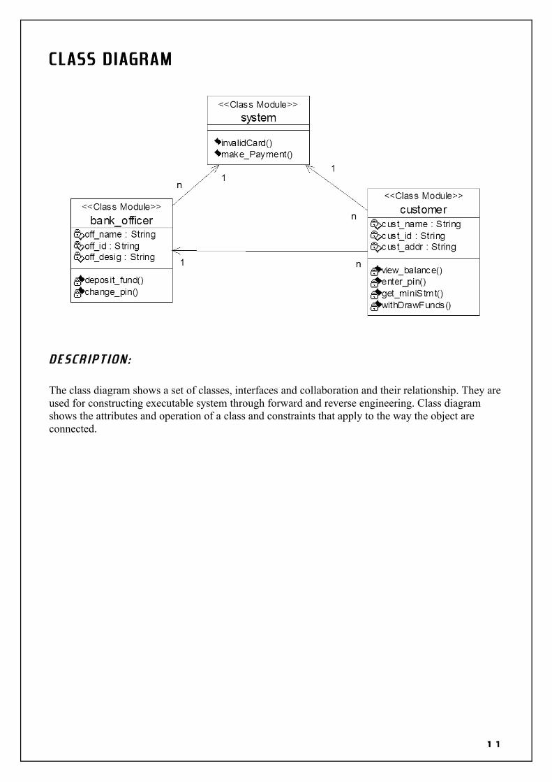
ACT IV ITY D IAGRAM
D E S C R I P T I O N :
Activity diagrams provide a way to model the workflow of a business process. You can also use activity diagrams to model code-specific information such as a class operation.
14

COMPONENT D IAGRAM
15

16

B a n k _ o f f i c e r c l a s s
VERSION 1.0 CLASSBEGIN MultiUse = -1 'True Persistable = 0 'NotPersistable DataBindingBehavior = 0 'vbNone DataSourceBehavior = 0 'vbNone MTSTransactionMode = 0 'NotAnMTSObjectENDAttribute VB_Name = "bank_officer"Attribute VB_GlobalNameSpace = FalseAttribute VB_Creatable = TrueAttribute VB_PredeclaredId = FalseAttribute VB_Exposed = FalseAttribute VB_Ext_KEY = "RVB_UniqueId" ,"46A668820290"Attribute VB_Ext_KEY = "RVB_ModelStereotype" ,"Class Module"Option Explicit
'##ModelId=46A6688F0167Private off_name As String
'##ModelId=46A66896002FPrivate off_id As String
'##ModelId=46A6689A00DBPrivate off_desig As String
'##ModelId=47024704008CPublic NewProperty As system
'##ModelId=46A668A30232Private Sub deposit_fund()
End Sub
'##ModelId=46A668AA00BBPrivate Sub change_pin()
End Sub
17

S y s t e m c l a s s
VERSION 1.0 CLASSBEGIN MultiUse = -1 'True Persistable = 0 'NotPersistable DataBindingBehavior = 0 'vbNone DataSourceBehavior = 0 'vbNone MTSTransactionMode = 0 'NotAnMTSObjectENDAttribute VB_Name = "system"Attribute VB_GlobalNameSpace = FalseAttribute VB_Creatable = TrueAttribute VB_PredeclaredId = FalseAttribute VB_Exposed = FalseAttribute VB_Ext_KEY = "RVB_UniqueId" ,"46A668B30186"Attribute VB_Ext_KEY = "RVB_ModelStereotype" ,"Class Module"Option Explicit
'##ModelId=46A668D90196Public Function invalidCard() As Boolean
End Function
'##ModelId=46A6690002DEPublic Function make_Payment() As Currency
End Function
18
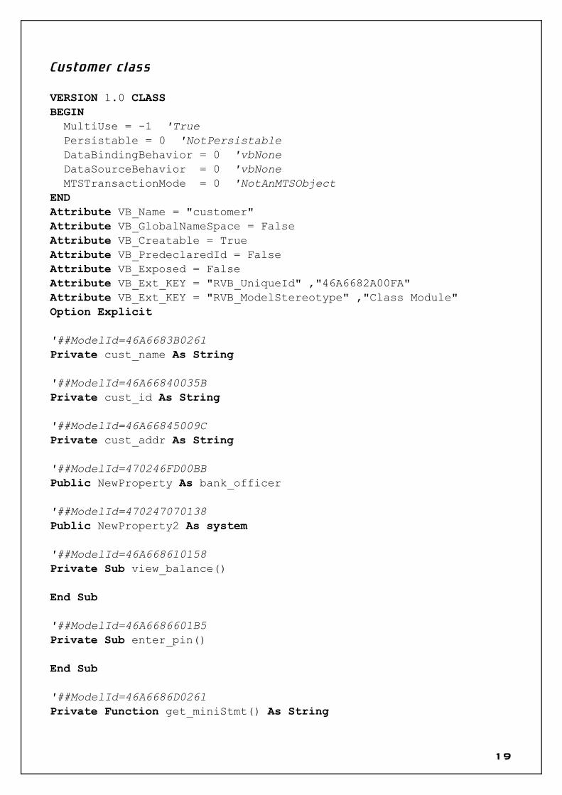
C u s t o m e r c l a s s
VERSION 1.0 CLASSBEGIN MultiUse = -1 'True Persistable = 0 'NotPersistable DataBindingBehavior = 0 'vbNone DataSourceBehavior = 0 'vbNone MTSTransactionMode = 0 'NotAnMTSObjectENDAttribute VB_Name = "customer"Attribute VB_GlobalNameSpace = FalseAttribute VB_Creatable = TrueAttribute VB_PredeclaredId = FalseAttribute VB_Exposed = FalseAttribute VB_Ext_KEY = "RVB_UniqueId" ,"46A6682A00FA"Attribute VB_Ext_KEY = "RVB_ModelStereotype" ,"Class Module"Option Explicit
'##ModelId=46A6683B0261Private cust_name As String
'##ModelId=46A66840035BPrivate cust_id As String
'##ModelId=46A66845009CPrivate cust_addr As String
'##ModelId=470246FD00BBPublic NewProperty As bank_officer
'##ModelId=470247070138Public NewProperty2 As system
'##ModelId=46A668610158Private Sub view_balance()
End Sub
'##ModelId=46A6686601B5Private Sub enter_pin()
End Sub
'##ModelId=46A6686D0261Private Function get_miniStmt() As String
19

End Function
'##ModelId=46A6687302CFPrivate Function withDrawFunds() As Currency
End Function
20

RESULT :
This project was carried out in a sequential manner to design and implement the “ATM SYSTEM”. Thus the outcome of the project is efficient. The ATM system caters the varied requirements of the user to perform various options.
21

22

23

EX.NO: DATE: ONLINE RESERVATION SYSTEMONLINE RESERVATION SYSTEM
A IM :To analyze, design and develop code for online reservation system using Rational Rose
software.
PROJECT SCOPE :The main scope of the project is to perform the reservations, modifications and cancellations
for train tickets with ease.
OBJECT IVE :The main objective of designing and developing an Online Reservation System is to make the
reservation and other related processes of this system more flexible and easier for the end users and without waiting in the long queue for the above mentioned processes.
INFRASTRUCTURE :
H A R D W A R E R E Q U I R E M E N T S♦ X86 based processor♦ RAM (128 MB min)♦ Hard Disc (40 GB)
S O F T W A R E R E Q U I R E M E N T S♦ Rational Rose Software
24

25

A BSTRACT :In the existing system all the transactions are done manually. These systems will have
to maintain the data in a hard file. While searching any data is too difficult to find those. Maintaining too many passenger details and ticket details in separate files are too
complicated. Similarly, it is too difficult to maintain the data for each and every manual transaction. So, the time utilization will be more for this manual system. In order to overcome these problems we have to propose the software for the existing method.
We have proposed system that would modernize the activities of reservation system. The developed system would perform all the functions of the manual system. Using this system we can save time and the operations will be performed with ease comparatively.
As System Analysts, we analyzed the existing system and found the following modules required to computerize the operations.
• Reservation Module – To reserve tickets to desired locations on a specific date.• Cancellation Module – To cancel the tickets, which was reserved for a specific date.
PROBLEM STATEMENT :The online ticket reservation system provides the passenger to reserve tickets in a virtual
counter. The passenger has the ability to reserve the tickets and also cancel the same if needed.
26

MOD ULA R DESCR IPT ION
R E S E R V A T I O N M O D U L E :This module allows the user to reserve tickets for a particular train on a particular
date if there is a vacancy. The user can know about the vacancy details of the train through the enquiry module.
C A N C E L L A T I O N M O D U L E :This module allows the user to cancel the tickets to a train for a particular date
through the reservation officer (System). This module permits the user to know the status of the reserved ticket before and after cancellation.
All these modules together prove to be a flexible Online Reservation System and it provides complete flexibility and reliability to the end users and it assures the desired performance.
27

28

USE CASE D IAGRAM
D E S C R I P T I O N :
Use-case diagrams graphically depict system behavior (use cases). These diagrams present a high level view of how the system is used as viewed from an outsider’s (actor’s) perspective.
29

CLASS D IAGRAM
D E S C R I P T I O N :
The class diagram shows a set of classes, interfaces and collaboration and their relationship. They are used for constructing executable system through forward and reserve engineering. Class diagram shows the attributes and operation of a class and constraints that apply to the way the object are connected.
30

SEQUENCE D IAGRAM
( T i c k e t r e s e r v a t i o n )
31

SEQUENCE D IAGRAM
( T i c k e t c a n c e l l a t i o n )
D E S C R I P T I O N :
A sequence diagram is a graphical view of a scenario that shows object interaction in a time-based sequence – what happens first, what happens next. Sequence diagrams establish the roles of objects and help provide essential information to determine class responsibilities and interfaces.
32

COLLA BORAT ION D IAGRAM(Ticket reservation)
COLLA BORAT ION D IAGRAM(Ticket cancellation)
D E S C R I P T I O N :
The collaboration diagram can be drawn from the sequential diagram by means of pressing F5. The collaboration diagram shows the overall flow of central towards each phase of the class
33

ACT IV ITY D IAGRAM
D E S C R I P T I O N :
Activity diagrams provide a way to model the workflow of a business process. You can also use activity diagrams to model code-specific information such as a class operation.
34

COMPONENT D IAGRAM
35

36

C o n t r o l l e r . h
#ifndef CONTROLLER_H_HEADER_INCLUDED_B8FDD4B8#define CONTROLLER_H_HEADER_INCLUDED_B8FDD4B8
//##ModelId=46AFA9F200DAclass controller{ public: //##ModelId=46AFAA4801A5 select a train();
private: //##ModelId=46AFAA340157 confirm cancellation();
//##ModelId=46AFAA3B02FD confirm reservation();
//##ModelId=46AFAA4100DA confirm availability();
};
#endif /* CONTROLLER_H_HEADER_INCLUDED_B8FDD4B8 */
c o n t r o l l e r . c p p
#include "controller.h"
//##ModelId=46AFAA4801A5controller::select a train(){}
//##ModelId=46AFAA340157controller::confirm cancellation(){}
//##ModelId=46AFAA3B02FDcontroller::confirm reservation(){}
37

//##ModelId=46AFAA4100DAcontroller::confirm availability(){}
p a s s e n g e r . h
#ifndef PASSENGER_H_HEADER_INCLUDED_B8FDA0D9#define PASSENGER_H_HEADER_INCLUDED_B8FDA0D9
//##ModelId=46AFA9BA033Cclass passenger{ public: //##ModelId=46AFA9D50251 submit();
protected: //##ModelId=46AFA9D30167 logout();
//##ModelId=46AFA9DD035B input train details();
private: //##ModelId=46AFA9CF02EE login();
//##ModelId=46AFA9D902EE cancel ticket();
//##ModelId=46AFA9C6001F String name;
//##ModelId=46AFA9C9001F Integer no;
};
#endif /* PASSENGER_H_HEADER_INCLUDED_B8FDA0D9 */
38

p a s s e n g e r . c p p
#include "passenger.h"
//##ModelId=46AFA9D50251passenger::submit(){}
//##ModelId=46AFA9D30167passenger::logout(){}
//##ModelId=46AFA9DD035Bpassenger::input train details(){}
//##ModelId=46AFA9CF02EEpassenger::login(){}
//##ModelId=46AFA9D902EEpassenger::cancel ticket(){}
s y s t e m . h
#ifndef SYSTEM_H_HEADER_INCLUDED_B8FDB515#define SYSTEM_H_HEADER_INCLUDED_B8FDB515
//##ModelId=46AFAA620242class system{ public: //##ModelId=46AFAA7A0271 show train list();
//##ModelId=46AFAA88036B issue form();
private: //##ModelId=46AFAA7F034B provide payment options();
39

};
#endif /* SYSTEM_H_HEADER_INCLUDED_B8FDB515 */
s y s t e m . c p p
#include "system.h"
//##ModelId=46AFAA7A0271system::show train list(){}
//##ModelId=46AFAA88036Bsystem::issue form(){}
//##ModelId=46AFAA7F034Bsystem::provide payment options(){}
40

RESULT :
This project was carried out in a sequential manner to design and implement the “ONLINE RESERVATION SYSTEM”. Thus the outcome of the project is efficient. The ONLINE RESERVATION SYSTEM caters the varied requirements of the user to perform various options.
41

42

43

EX.NO: DATE: ONLINE QUIZ SYSTEMONLINE QUIZ SYSTEM
A IM :To analyze, design and develop code for online quiz system using Rational Rose software.
PROJECT SCOPE :The main scope of the project is to provide a user-friendly online quiz system, which enables
the participant to take part in online quiz system and make the best of it.
OBJECT IVE :The main objective of designing and developing an Online Quiz System is to enable the
participants i.e. the end users of this system to gain the complete wisdom through this flexible and reliable system. This system has been developed in such a way that there exists a two way communication between the participants i.e. the end user and the coordinator. The questions, their answers and the grades and scores of the participants are stored in a database and retrieved as and when required.
INFRASTRUCTURE :
H A R D W A R E R E Q U I R E M E N T S♦ X86 based processor♦ RAM (128 MB min)♦ Hard Disc (40 GB)
S O F T W A R E R E Q U I R E M E N T S♦ Rational Rose Software
44

45

A BSTRACT :
In the existing quiz system all the processing are done manually. These systems will have to maintain the data in a hard file. While searching any data it is too difficult to find those.
Maintaining too many questions and answers in separate files are too complicated. Similarly, it is too difficult to maintain the data for each and every activity. So, the time utilization will be more for this manual system. In order to overcome these problems we have to propose the system, which overcomes the problem of the existing method.
We have proposed a system that would modernize the activities of online quiz system. The developed system would perform all the functions of the manual system. Using this system we can save time and the operations will be performed with ease comparatively.
As System Analysts, we analyzed the existing system and found the following modules required to computerize the operations.
• Registration Module – To register the names and personal details of the participants, which will be stored in the database.
• Display Module – To display the questions to the participants and the corresponding answers when required.
• Evaluation Module – To verify the answers of the participants with that of db.• Announcement Module – To announce the results of the quiz and the winners of the
competition.
PROBLEM STATEMENT :The online quiz system provides a user-friendly interface for efficient way of evaluating the
participants. The system is designed in such a way that the participants can easily understand various elements of the user interface.
46

MOD ULA R DESCR IPT ION
R E G I S T R A T I O N M O D U L E :This module enables the end users to register themselves to the online quiz
competition through two-way communication between the coordinator and the participant. This is the most important module as it maintains the details of the participants in the database and it is the preliminary stage of the online quiz system.
D I S P L A Y M O D U L E :This module provides the user with the fields i.e. the questions for which they have to
answer and it displays the answers of those questions when required by the coordinator.
E V A L U A T I O N M O D U L E :This module evaluates the answers that are given by the users i.e. the participants with
that of the corresponding answers in the database. Either they are correct or wrong, in both the cases the scores of the corresponding participant or team will be updated accordingly.
A N N O U N C E M E N T M O D U L E :This module is used to display the results of the quiz competition irrespective of the
status of the result and it also displays the scores acquired by each participant or team at the end of the quiz competition.
All these modules together prove to be a flexible Online Quiz System and it provides complete flexibility and reliability to the end users and it assures of the desired performance.
47

48

USE CASE D IAGRAM
D E S C R I P T I O N :
Use-case diagrams graphically depict system behavior (use cases). These diagrams present a high level view of how the system is used as viewed from an outsider’s (actor’s) perspective.
49

CLASS D IAGRAM
D E S C R I P T I O N :
The class diagram shows a set of classes, interfaces and collaboration and their relationship. They are used for constructing executable system through forward and reserve engineering. Class diagram shows the attributes and operation of a class and constraints that apply to the way the object are connected.
50

SEQUENCE D IAGRAM
( L o g i n )
51

SEQUENCE D IAGRAM(Quiz)
D E S C R I P T I O N :
A sequence diagram is a graphical view of a scenario that shows object interaction in a time-based sequence – what happens first, what happens next. Sequence diagrams establish the roles of objects and help provide essential information to determine class responsibilities and interfaces.
52

COLLA BORAT ION D IAGRAM
( L o g i n )
COLLA BORAT ION D IAGRAM
( Q u i z )
D E S C R I P T I O N :
The collaboration diagram can be drawn from the sequential diagram by means of pressing F5. The collaboration diagram shows the overall flow of central towards each phase of the class
53

ACT IV ITY D IAGRAM
D E S C R I P T I O N :
Activity diagrams provide a way to model the workflow of a business process. You can also use activity diagrams to model code-specific information such as a class operation.
54

COMPONENT D IAGRAM
55

56

C o n t r o l l e r . h
#ifndef CONTROLLER_H_HEADER_INCLUDED_B8FDFCA8#define CONTROLLER_H_HEADER_INCLUDED_B8FDFCA8#include "Participant.h"
//##ModelId=46818954002Eclass Controller : public Participant{ public: //##ModelId=468189790213 String uploadAnswers();
//##ModelId=4681897C035B validate();
//##ModelId=468189800222 String provideResult();
private: //##ModelId=470241CF0138 String name;
//##ModelId=470241E200FA Integer time;
};
#endif /* CONTROLLER_H_HEADER_INCLUDED_B8FDFCA8 */
c o n t r o l l e r . c p p
#include "Controller.h"
//##ModelId=468189790213String Controller::uploadAnswers(){}
//##ModelId=4681897C035BController::validate(){}
//##ModelId=468189800222
57

String Controller::provideResult(){}
p a r t i c i p a n t . h
#ifndef PARTICIPANT_H_HEADER_INCLUDED_B8FDB6BB#define PARTICIPANT_H_HEADER_INCLUDED_B8FDB6BB
//##ModelId=468189320196class Participant{ public: //##ModelId=4681894A0213 Variant read();
//##ModelId=4681894D0148 String answer();
private: //##ModelId=47023DD901F4 String name;
//##ModelId=47023E0F02DE Integer age;
//##ModelId=47023E370186 String qualification;
};
#endif /* PARTICIPANT_H_HEADER_INCLUDED_B8FDB6BB */
p a r t i c i p a n t . c p p
#include "Participant.h"
//##ModelId=4681894A0213Variant Participant::read(){}
58

//##ModelId=4681894D0148String Participant::answer(){}
59

RESULT :
This project was carried out in a sequential manner to design and implement the “ONLINE QUIZ SYSTEM”. Thus the outcome of the project is efficient. The ONLINE QUIZ SYSTEM caters the varied requirements of the user to perform various options.
60

61

62

EX.NO: DATE: STOCK MAINTENANCE SYSTEMSTOCK MAINTENANCE SYSTEM
A IM :To analyze, design and develop code for Stock Maintenance System using Rational Rose
software.
PROJECT SCOPE :The main scope of the project is to provide a exhaustive, flexible and reliable Stock
Maintenance system which would be beneficial for both stock manager and retailer.
OBJECT IVE :The main objective of designing and developing a Stock Maintenance System is to provide
with a system which proves to be mutually beneficial i.e. it benefits both the Stock Manager and the Retailer. The complete activities and the processes right from product’s manufacture till the product gets sold out, every single activity is incorporated in this system.
INFRASTRUCTURE :
H A R D W A R E R E Q U I R E M E N T S♦ X86 based processor♦ RAM (128 MB min)♦ Hard Disc (40 GB)
S O F T W A R E R E Q U I R E M E N T S♦ Rational Rose Software♦ Visual C++ 6.0
63

64
A BSTRACT :The Stock Maintenance System is highly unique because of its distinguished activities and
behavior. It sounds to be different because of its classified nature. It starts right from the manufacture of a product and it covers up the entire life cycle till the customer purchases the product. The maintenance of these stocks proves to be challenging as it has many cases to concern.
The special cases aroused from this stock maintenance system such as handling the damaged and expired stock are appropriately designed to match the needs of the real world.
In the existing system all the processing are done manually. These systems will have to maintain the data in a hard file. While searching any data it is too difficult to find those.
Maintaining too many data about products in separate files are too complicated. Similarly, it is too difficult to maintain the data for each and every activity. So, the time utilization will be more for this manual system. In order to overcome these problems we have to propose the system that overcomes the problem of the existing method.
We have proposed a system that would modernize the activities of stock maintenance system. The developed system would perform all the functions of the manual system. Using this system we can save time and the operations will be performed with ease comparatively.
PROBLEM STATEMENT :The stock maintenance system provides an easy way to have a check on the stock availability and also the various requests of them by customer.
65

MOD ULA R DESCR IPT ION
O R D E R M O D U L E :This module is necessary to get the request from the customer for any product
and also this module communicates with the stock module to determine the availability of stock.
S T O C K M O D U L E :This module is the one, which is necessary to add information about all the
items that are to be stocked. This module provides the stock availability and also data required for new orders.
66

67

USE CASE D IAGRAM
D E S C R I P T I O N :
Use-case diagrams graphically depict system behavior (use cases). These diagrams present a high level view of how the system is used as viewed from an outsider’s (actor’s) perspective.
68

CLASS D IAGRAM
D E S C R I P T I O N :
The class diagram shows a set of classes, interfaces and collaboration and their relationship. They are used for constructing executable system through forward and reverse engineering. Class diagram shows the attributes and operation of a class and constraints that apply to the way the object are connected.
69

SEQUENCE D IAGRAM
D E S C R I P T I O N :
A sequence diagram is a graphical view of a scenario that shows object interaction in a time-based sequence – what happens first, what happens next. Sequence diagrams establish the roles of objects and help provide essential information to determine class responsibilities and interfaces.
70

COLLA BORAT ION D IAGRAM
( L o g i n )
D E S C R I P T I O N :
The collaboration diagram can be drawn from the sequential diagram by means of pressing F5. The collaboration diagram shows the overall flow of central towards each phase of the class
71

ACT IV ITY D IAGRAM
D E S C R I P T I O N :
Activity diagrams provide a way to model the workflow of a business process. You can also use activity diagrams to model code-specific information such as a class operation.
72

COMPONENT D IAGRAM
73

74

S y s t e m . h
// Copyright (C) 1991 - 1999 Rational Software Corporation
#if defined (_MSC_VER) && (_MSC_VER >= 1000)#pragma once#endif#ifndef _INC_SYSTEM_46AFAC6800BB_INCLUDED#define _INC_SYSTEM_46AFAC6800BB_INCLUDED
class accountant;class producer;class distributor;
//##ModelId=46AFAC6800BBclass system {public:
//##ModelId=470274FA029Fdistributor* thedistributor;
//##ModelId=47027500037Aproducer* theproducer;
//##ModelId=470275040177accountant* theaccountant;
//##ModelId=46AFACC1030DcheckAvailability();
private://##ModelId=46AFAC8000DAlogin();
//##ModelId=46AFACCA0213logout();
};
#endif /* _INC_SYSTEM_46AFAC6800BB_INCLUDED */
s y s t e m . c p p
// Copyright (C) 1991 - 1999 Rational Software Corporation
#include "stdafx.h"#include "customer.h"
75

#include "system.h"#include "accountant.h"
//##ModelId=46AFAC2B00EAaccountant::login(){}
//##ModelId=46AFAC3600BBaccountant::getPayment(){}
d i s t r i b u t o r . h
// Copyright (C) 1991 - 1999 Rational Software Corporation
#if defined (_MSC_VER) && (_MSC_VER >= 1000)#pragma once#endif#ifndef _INC_DISTRIBUTOR_46AFACF601D4_INCLUDED#define _INC_DISTRIBUTOR_46AFACF601D4_INCLUDED
//##ModelId=46AFACF601D4class distributor {public:
//##ModelId=46AFAD120290provideReplacement();
//##ModelId=46AFAD1D035BprovideStockDetails();
private://##ModelId=46AFAD050290String name;
};
#endif /* _INC_DISTRIBUTOR_46AFACF601D4_INCLUDED */
d i s t r i b u t o r . c p p
76

// Copyright (C) 1991 - 1999 Rational Software Corporation
#include "stdafx.h"#include "distributor.h"
//##ModelId=46AFAD120290distributor::provideReplacement(){}
//##ModelId=46AFAD1D035Bdistributor::provideStockDetails(){}
c u s t o m e r . h
// Copyright (C) 1991 - 1999 Rational Software Corporation
#if defined (_MSC_VER) && (_MSC_VER >= 1000)#pragma once#endif#ifndef _INC_CUSTOMER_46AFABA5031C_INCLUDED#define _INC_CUSTOMER_46AFABA5031C_INCLUDED
//##ModelId=46AFABA5031Cclass customer {private:
//##ModelId=46AFABB50167String name;
//##ModelId=46AFABB80261String id;
//##ModelId=46AFABD9002Elogin();
//##ModelId=46AFABDC0109orderProduct();
//##ModelId=46AFABE20399cancelOrder();
//##ModelId=46AFABE6007D77

receiveStock();
//##ModelId=46AFABF40128doPayment();
//##ModelId=46AFABFD01E4logout();
};
#endif /* _INC_CUSTOMER_46AFABA5031C_INCLUDED */
c u s t o m e r . c p p
// Copyright (C) 1991 - 1999 Rational Software Corporation
#include "stdafx.h"#include "customer.h"
//##ModelId=46AFABD9002Ecustomer::login(){}
//##ModelId=46AFABDC0109customer::orderProduct(){}
//##ModelId=46AFABE20399customer::cancelOrder(){}
//##ModelId=46AFABE6007Dcustomer::receiveStock(){}
//##ModelId=46AFABF40128customer::doPayment(){}
//##ModelId=46AFABFD01E4customer::logout()
78

{}
a c c o u n t a n t . h
// Copyright (C) 1991 - 1999 Rational Software Corporation
#if defined (_MSC_VER) && (_MSC_VER >= 1000)#pragma once#endif#ifndef _INC_ACCOUNTANT_46AFAC150109_INCLUDED#define _INC_ACCOUNTANT_46AFAC150109_INCLUDED
class customer;class system;
//##ModelId=46AFAC150109class accountant {public:
//##ModelId=47027508000Fcustomer* thecustomer;
private://##ModelId=46AFAC240242String name;
//##ModelId=46AFAC2B00EAlogin();
//##ModelId=46AFAC3600BBgetPayment();
};
#endif /* _INC_ACCOUNTANT_46AFAC150109_INCLUDED */
a c c o u n t a n t . c p p
// Copyright (C) 1991 - 1999 Rational Software Corporation
#include "stdafx.h"#include "customer.h"#include "system.h"#include "accountant.h"
79

//##ModelId=46AFAC2B00EAaccountant::login(){}
//##ModelId=46AFAC3600BBaccountant::getPayment(){}
p r o d u c e r . h
// Copyright (C) 1991 - 1999 Rational Software Corporation
#if defined (_MSC_VER) && (_MSC_VER >= 1000)#pragma once#endif#ifndef _INC_PRODUCER_46AFACD20167_INCLUDED#define _INC_PRODUCER_46AFACD20167_INCLUDED
class distributor;
//##ModelId=46AFACD20167class producer {public:
//##ModelId=4702750C01B5distributor* thedistributor;
protected://##ModelId=46AFACE20271getstockdetails();
//##ModelId=46AFACEA036BcheckAvailability();
private://##ModelId=46AFACDA00BBString name;
};
#endif /* _INC_PRODUCER_46AFACD20167_INCLUDED */
80

p r o d u c e r . c p p
// Copyright (C) 1991 - 1999 Rational Software Corporation
#include "stdafx.h"#include "distributor.h"#include "producer.h"
//##ModelId=46AFACE20271producer::getstockdetails(){}
//##ModelId=46AFACEA036Bproducer::checkAvailability(){}
81

RESULT :
This project was carried out in a sequential manner to design and implement the “STOCK MAINTENANCE SYSTEM”. Thus the outcome of the project is efficient. The STOCK MAINTENANCE SYSTEM caters the varied requirements of the user to perform various options.
82

83

84
EX.NO: DATE: STUDENT MARK ANALYSIS SYSTEMSTUDENT MARK ANALYSIS SYSTEM
A IM :To analyze, design and develop code for Student Mark Analysis system using Rational Rose
software.
PROJECT SCOPE :The main scope of the project is to develop a system that effectively manages the marks and
grades of the students and update them regularly through the authenticated users.
OBJECT IVE :The main objective of designing and developing a Student Mark Analysis System is to enable
the administrator or any other authenticated person to record, view or upgrade the marks and grades of the students. This system is specifically meant to manipulate and manage the marks and grades of the students but not to get into the personal details of the students
INFRASTRUCTURE :
H A R D W A R E R E Q U I R E M E N T S♦ X86 based processor♦ RAM (128 MB min)♦ Hard Disc (40 GB)
S O F T W A R E R E Q U I R E M E N T S♦ Rational Rose Software♦ Visual Basic 6.0
85

86

A BSTRACT :The Student Mark Analysis System is very important because of its common usage in
most of the academic institutions. It proves to be the commonest system as it find its application in almost all the educational institutions irrespective of its strength and location.. The maintenance of this system proves to be challenging as it has many cases to concern.
In the existing system all the processing are done manually. These systems will have to maintain the data in a hard file. While searching any data it is too difficult to find those.
Maintaining too many data about products in separate files are too complicated. Similarly, it is too difficult to maintain the data for each and every activity. So, the time utilization will be more for this manual system. In order to overcome these problems we have to propose the system that overcomes the problem of the existing method.
The developed system would perform all the functions of the manual system. Using this system we can save time and the operations will be performed with ease comparatively.
As System Analysts, we analyzed the existing system and found the following modules required to computerize the operations.
a) Record Grades Module – To record the grades of each and every student..b) View Grades Module – To view the grades of any student.
PROBLEM STATEMENT :The student mark analysis system enables the authenticated users to effectively maintain the marks of the students. The system provides automated grading for students.
87

MOD ULA R DESCR IPT ION
R E C O R D M A R K S M O D U L E :This module enables the authenticated users to record the marks and thereby
their respective grades in a database. This is the most important module as it maintains the details of the marks scored by the students in the database and it is the first and the foremost step in this system.
V I E W G R A D E S M O D U L E :This module permits the respective users to view their grades as and when
necessary after their identification through their login name and password. This module proves to be the simplest as it does not allow the user to modify or update any information except viewing them.
U P D A T E M A R K S M O D U L E :This module enables the authenticated users to update the marks of the students
after each and every test in order to update the data to the present existing grades of the students. This module just allows the user to modify or update the grades of the students alone but not their personal details. This module does not allow any user just like that only authenticated users are allowed to update the necessary data after their identification through their login name and password.
88

89

USE CASE D IAGRAM
D E S C R I P T I O N :
Use-case diagrams graphically depict system behavior (use cases). These diagrams present a high level view of how the system is used as viewed from an outsider’s (actor’s) perspective.
90

CLASS D IAGRAM
D E S C R I P T I O N :
The class diagram shows a set of classes, interfaces and collaboration and their relationship. They are used for constructing executable system through forward and reverse engineering. Class diagram shows the attributes and operation of a class and constraints that apply to the way the object are connected.
91

SEQUENCE D IAGRAM
D E S C R I P T I O N :
A sequence diagram is a graphical view of a scenario that shows object interaction in a time-based sequence – what happens first, what happens next. Sequence diagrams establish the roles of objects and help provide essential information to determine class responsibilities and interfaces.
92

COLLA BORAT ION D IAGRAM
D E S C R I P T I O N :
The collaboration diagram can be drawn from the sequential diagram by means of pressing F5. The collaboration diagram shows the overall flow of central towards each phase of the class
93

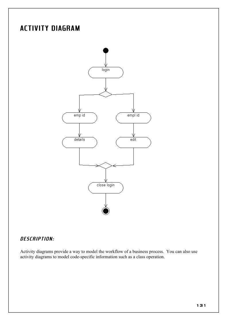
ACT IV ITY D IAGRAM
D E S C R I P T I O N :
Activity diagrams provide a way to model the workflow of a business process. You can also use activity diagrams to model code-specific information such as a class operation.
94

COMPONENT D IAGRAM
95

96

S t a f f c l a s s
VERSION 1.0 CLASSBEGIN MultiUse = -1 'True Persistable = 0 'NotPersistable DataBindingBehavior = 0 'vbNone DataSourceBehavior = 0 'vbNone MTSTransactionMode = 0 'NotAnMTSObjectENDAttribute VB_Name = "staff"Attribute VB_GlobalNameSpace = FalseAttribute VB_Creatable = TrueAttribute VB_PredeclaredId = FalseAttribute VB_Exposed = FalseAttribute VB_Ext_KEY = "RVB_UniqueId" ,"46AFAE0B01D4"Attribute VB_Ext_KEY = "RVB_ModelStereotype" ,"Class Module"Option Explicit
'##ModelId=4702609803A9Implements system
'##ModelId=46AFAE270148Private name As String
'##ModelId=470263C1005DPrivate msystemObject As New system
'##ModelId=46AFAE2B0167Private Sub enter_mark()
End Sub
'##ModelId=46AFAE3001A5Private Sub update_mark()
End Sub
'##ModelId=46AFAE350280Public Sub get_grades()
End Sub
M r k c l a s s
VERSION 1.0 CLASSBEGIN
97
MultiUse = -1 'True Persistable = 0 'NotPersistable DataBindingBehavior = 0 'vbNone DataSourceBehavior = 0 'vbNone MTSTransactionMode = 0 'NotAnMTSObjectENDAttribute VB_Name = "system"Attribute VB_GlobalNameSpace = FalseAttribute VB_Creatable = TrueAttribute VB_PredeclaredId = FalseAttribute VB_Exposed = FalseAttribute VB_Ext_KEY = "RVB_UniqueId" ,"46AFAE0100EA"Attribute VB_Ext_KEY = "RVB_ModelStereotype" ,"Class Module"Option Explicit
'##ModelId=46AFAE150399Private Sub maintain_students_marks()
End Sub
'##ModelId=46AFAE1E0203Friend Sub login()
End Sub
'##ModelId=46AFAE2003A9Friend Sub logout()
End Sub
98

RESULT :
This project was carried out in a sequential manner to design and implement the “STUDENT MARK ANALYSIS SYSTEM”. Thus the outcome of the project is efficient. The STUDENT MARK ANALYSIS SYSTEM caters the varied requirements of the user to perform various options.
99

100

101

EX.NO: DATE : COURSE REGISTRATION SYSTEMCOURSE REGISTRATION SYSTEM
A IM :To analyze, design and develop code for Course registration System using Rational Rose
software.
PROJECT SCOPE :The main scope of the project is to provide a exhaustive, flexible and reliable course
registration system which would be easier for both student and registrar.
OBJECT IVE :The main objective of designing and developing a Course registration System is to provide
with a system that proves to be mutually beneficial i.e. it benefits both student and registrar.
INFRASTRUCTURE :
H A R D W A R E R E Q U I R E M E N T S♦ X86 based processor♦ RAM (128 MB min)♦ Hard Disc (40 GB)
S O F T W A R E R E Q U I R E M E N T S♦ Rational Rose Software♦ Visual C++ 6.0
102

103

A BSTRACT :In today’s world the number of students pursuing higher education in colleges has increased
widely. Hence in reputed institutions, where the number of students registering for particular course is quite big, it is difficult to perform registration manually.
Thus it has necessitated the need for complete automated Course Registration System. This system allows user with a valid User ID and Password to log on to the System. It also allows the user to fill the application form, which contains details like student details and the marks. The System analyses the marks and allots ranking for the students. The System also allows the user to view the selected candidate list and rank of that particular candidate.
PROBLEM STATEMENT :The course registration system provides a good interface so that the user can select the college
needed without other’s help except the supervision from administrator.
104

MOD ULA R DESCR IPT ION
R E G I S T R A T I O N M O D U L E :This module enables a student to select a course from a given set of courses. It
is this module that acts as an interface between the student and the registrar.
M A I N T E N A N C E M O D U L E :This module is necessary to store all the information about the student to the
database. This module also has the provision to retrieve the data from the database system.
105

106

USE CASE D IAGRAM
D E S C R I P T I O N :
Use-case diagrams graphically depict system behavior (use cases). These diagrams present a high level view of how the system is used as viewed from an outsider’s (actor’s) perspective.
107

CLASS D IAGRAM
D E S C R I P T I O N :
The class diagram shows a set of classes, interfaces and collaboration and their relationship. They are used for constructing executable system through forward and reverse engineering. Class diagram shows the attributes and operation of a class and constraints that apply to the way the object are connected.
108

SEQUENCE D IAGRAM
( S t u d e n t s y s t e m )
D E S C R I P T I O N :
A sequence diagram is a graphical view of a scenario that shows object interaction in a time-based sequence – what happens first, what happens next. Sequence diagrams establish the roles of objects and help provide essential information to determine class responsibilities and interfaces.
109

COLLA BORAT ION D IAGRAM
( S t u d e n t s y s t e m )
D E S C R I P T I O N :
The collaboration diagram can be drawn from the sequential diagram by means of pressing F5. The collaboration diagram shows the overall flow of central towards each phase of the class
110

ACT IV ITY D IAGRAM
D E S C R I P T I O N :
Activity diagrams provide a way to model the workflow of a business process. You can also use activity diagrams to model code-specific information such as a class operation.
111

COMPONENT D IAGRAM
112

113

S y s t e m . h
// Copyright (C) 1991 - 1999 Rational Software Corporation
#if defined (_MSC_VER) && (_MSC_VER >= 1000)#pragma once#endif#ifndef _INC_SYSTEM_46A666A20203_INCLUDED#define _INC_SYSTEM_46A666A20203_INCLUDED
class student;
//##ModelId=46A666A20203class system {public:
//##ModelId=4709D2E901D5student* thestudent;
protected://##ModelId=46A666FE0280login();
private://##ModelId=46A66702001FmaintainStudentnfo();
};
#endif /* _INC_SYSTEM_46A666A20203_INCLUDED */
s y s t e m . c p p
// Copyright (C) 1991 - 1999 Rational Software Corporation
#include "stdafx.h"#include "student.h"#include "system.h"
//##ModelId=46A666FE0280system::login(){}
114

//##ModelId=46A66702001Fsystem::maintainStudentnfo(){}
s t u d e n t . h
// Copyright (C) 1991 - 1999 Rational Software Corporation
#if defined (_MSC_VER) && (_MSC_VER >= 1000)#pragma once#endif#ifndef _INC_STUDENT_46A665680261_INCLUDED#define _INC_STUDENT_46A665680261_INCLUDED
//##ModelId=46A665680261class student {public:
//##ModelId=46A665B102EEregisterForCourse();
//##ModelId=46A665BD039AviewReport();
//##ModelId=46A665C4034CviewCatalog();
private://##ModelId=46A66592033CString stu_name;
//##ModelId=46A6659F03C9String stu_dept;
};
#endif /* _INC_STUDENT_46A665680261_INCLUDED */
s t u d e n t . c p p
// Copyright (C) 1991 - 1999 Rational Software Corporation
#include "stdafx.h"#include "student.h"
115

//##ModelId=46A665B102EEstudent::registerForCourse(){}
//##ModelId=46A665BD039Astudent::viewReport(){}
//##ModelId=46A665C4034Cstudent::viewCatalog(){}
r e g i s t r a r . h
// Copyright (C) 1991 - 1999 Rational Software Corporation
#if defined (_MSC_VER) && (_MSC_VER >= 1000)#pragma once#endif#ifndef _INC_REGISTRAR_46A6666D0148_INCLUDED#define _INC_REGISTRAR_46A6666D0148_INCLUDED
class student;
//##ModelId=46A6666D0148class registrar {public:
//##ModelId=47024EB9033Cstudent* thestudent;
private://##ModelId=46A6667B030DString showCatalog();
//##ModelId=46A66683002FcloseRegistration();
};
#endif /* _INC_REGISTRAR_46A6666D0148_INCLUDED */
116

r e g i s t r a r . c p p
// Copyright (C) 1991 - 1999 Rational Software Corporation
#include "stdafx.h"#include "student.h"#include "registrar.h"
//##ModelId=46A6667B030DString registrar::showCatalog(){
// TODO: Add your specialized code here.// NOTE: Requires a correct return value to compile.
}
//##ModelId=46A66683002Fregistrar::closeRegistration(){}
117

RESULT :
This project was carried out in a sequential manner to design and implement the “COURSE REGISTRATION SYSTEM”. Thus the outcome of the project is efficient. The COURSE REGISTRATION SYSTEM caters the varied requirements of the user to perform various options.
118

119

120

EX.NO: DATE : PAYROLL SYSTEMPAYROLL SYSTEM
A IM :To analyze, design and develop code for Payroll System using Rational Rose software.
PROJECT SCOPE :The main scope of the project is to provide an exhaustive, flexible and reliable payroll system
that would be easier for both manager and employee.
OBJECT IVE :The main objective of designing and developing a Payroll System is to provide with a system
that proves to be mutually beneficial i.e. it benefits both employee and manager.
INFRASTRUCTURE :
H A R D W A R E R E Q U I R E M E N T S♦ X86 based processor♦ RAM (128 MB min)♦ Hard Disc (40 GB)
S O F T W A R E R E Q U I R E M E N T S♦ Rational Rose Software
121

122

A BSTRACT :Each and every organization or institution or firm or a corporate office will have employees.
If there were employees, then there would be a need to provide salary. The process of determining the salary is a complicated affair.
Thus it has necessitated the need for complete automated Payroll System. This system allows user with a valid User ID and Password to log on to the System. It also allows the user to determine the salary of a particular employee based on their designation and other constraints. The System provides an easy to use interface enabling the user to maintain employee records.
PROBLEM STATEMENT :The software should be able to provide the salary details when the ID number is given. It should also give details of payment; fast date of payment etc. The employer should be able to either increment or decrement any part of the salary. The total amount should be automatically updated after each manipulation.
123

MOD ULA R DESCR IPT ION
A D D M O D U L E :This module enables the manager to add new employees. This module is the
most important one as this is the basic prerequisite for a payroll system.
V I E W M O D U L E :This module permits the manager to view the details of all the employees and
their salaries. This module also allows an employee to view his/her salary information.
E D I T M O D U L E :This module enables the manager to edit the salary details of any employee.
This module also has the ability to enable the manager to remove an employee from the firm.
124

125

USE CASE D IAGRAM
D E S C R I P T I O N :
Use-case diagrams graphically depict system behavior (use cases). These diagrams present a high level view of how the system is used as viewed from an outsider’s (actor’s) perspective.
126

CLASS D IAGRAM
D E S C R I P T I O N :
The class diagram shows a set of classes, interfaces and collaboration and their relationship. They are used for constructing executable system through forward and reverse engineering. Class diagram shows the attributes and operation of a class and constraints that apply to the way the object are connected.
127

SEQUENCE D IAGRAM
( G e n e r a l v i e w )
128

SEQUENCE D IAGRAM
( S p e c i f i e d v i e w )
D E S C R I P T I O N :
A sequence diagram is a graphical view of a scenario that shows object interaction in a time-based sequence – what happens first, what happens next. Sequence diagrams establish the roles of objects and help provide essential information to determine class responsibilities and interfaces.
129

COLLA BORAT ION D IAGRAM
( G e n e r a l v i e w )
COLLA BORAT ION D IAGRAM
( S p e c i f i c v i e w )
D E S C R I P T I O N :
The collaboration diagram can be drawn from the sequential diagram by means of pressing F5. The collaboration diagram shows the overall flow of central towards each phase of the class
130
ACT IV ITY D IAGRAM
D E S C R I P T I O N :
Activity diagrams provide a way to model the workflow of a business process. You can also use activity diagrams to model code-specific information such as a class operation.
131

COMPONENT D IAGRAM
132

133

E d i t d e t a i l s . h
#ifndef EDIT_DETAILS_H_HEADER_INCLUDED_B8FD1D6C#define EDIT_DETAILS_H_HEADER_INCLUDED_B8FD1D6C
//##ModelId=470282A10128class edit details{ public: //##ModelId=470282AE038A delete();
//##ModelId=470282BA002E edit();
//##ModelId=470282BD0196 view all();
private: //##ModelId=470282C50399 String employee id;
//##ModelId=470282D40109 String employee name;
};
#endif /* EDIT_DETAILS_H_HEADER_INCLUDED_B8FD1D6C */
e d i t d e t a i l s . c p p
#include "edit details.h"
//##ModelId=470282AE038Aedit details::delete(){}
//##ModelId=470282BA002Eedit details::edit(){}
//##ModelId=470282BD0196
134

edit details::view all(){}
v i e w d e t a i l s . h
#ifndef VIEW_DETAILS_H_HEADER_INCLUDED_B8FD6630#define VIEW_DETAILS_H_HEADER_INCLUDED_B8FD6630
//##ModelId=470282200213class view details{ public: //##ModelId=47028233009C view();
//##ModelId=4702823B031C add();
private: //##ModelId=470282450186 String employee id;
};
#endif /* VIEW_DETAILS_H_HEADER_INCLUDED_B8FD6630 */
e d i t d e t a i l s . c p p
#include "view details.h"
//##ModelId=47028233009Cview details::view(){}
//##ModelId=4702823B031Cview details::add(){}
s p e c i a l l o g i n . h
#ifndef SPECIAL_LOGIN_H_HEADER_INCLUDED_B8FD1350
135

#define SPECIAL_LOGIN_H_HEADER_INCLUDED_B8FD1350
//##ModelId=470282590000class special login{ public: //##ModelId=4702826C00AB m_login();
private: //##ModelId=4702827C0128 String m_username;
//##ModelId=4702828D01E4 String m_password;
};
#endif /* SPECIAL_LOGIN_H_HEADER_INCLUDED_B8FD1350 */
special login.cpp
#include "special login.h"
//##ModelId=4702826C00ABspecial login::m_login(){}
l o g i n . h
#ifndef LOGIN_H_HEADER_INCLUDED_B8FD6273#define LOGIN_H_HEADER_INCLUDED_B8FD6273
//##ModelId=470281CE02FDclass login{ public: //##ModelId=470281D90167 next form();
private: //##ModelId=470281F3036B String user name;
136

//##ModelId=4702821102BF String password;
};
#endif /* LOGIN_H_HEADER_INCLUDED_B8FD6273 */
l o g i n . c p p
#include "login.h"
//##ModelId=470281D90167login::next form(){}
137

RESULT :
This project was carried out in a sequential manner to design and implement the “PAYROLL SYSTEM”. Thus the outcome of the project is efficient. The PAYROLL SYSTEM caters the varied requirements of the user to perform various options.
138

139

A N S I C + +
• Create a new component in Component View.• Double click the new component created to open component specification.• Set the following setting for stereotype and language.
• Right click the newly created component in the Component view and select the following.
• Once generate code is selected the following dialog pops up.
140

• Select the appropriate directory for storing the generated code.
• Now the following dialog pops up to select the required class, for which the code has to be generated.
• After selecting the required classes select OK.
• The following dialog is displayed confirming the code generation.
141
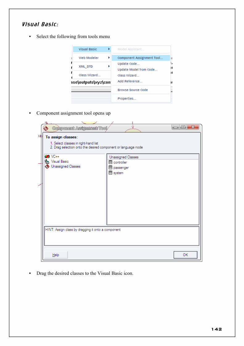
V i s u a l B a s i c :
• Select the following from tools menu
• Component assignment tool opens up
• Drag the desired classes to the Visual Basic icon.
142

• Select yes and continue to select a new standard exe.
• Select OK.
143

• Select OK.
• Now right click the newly created component in the Component View and select as follows.
• Select the desired component and then select Next and then Finish.
144
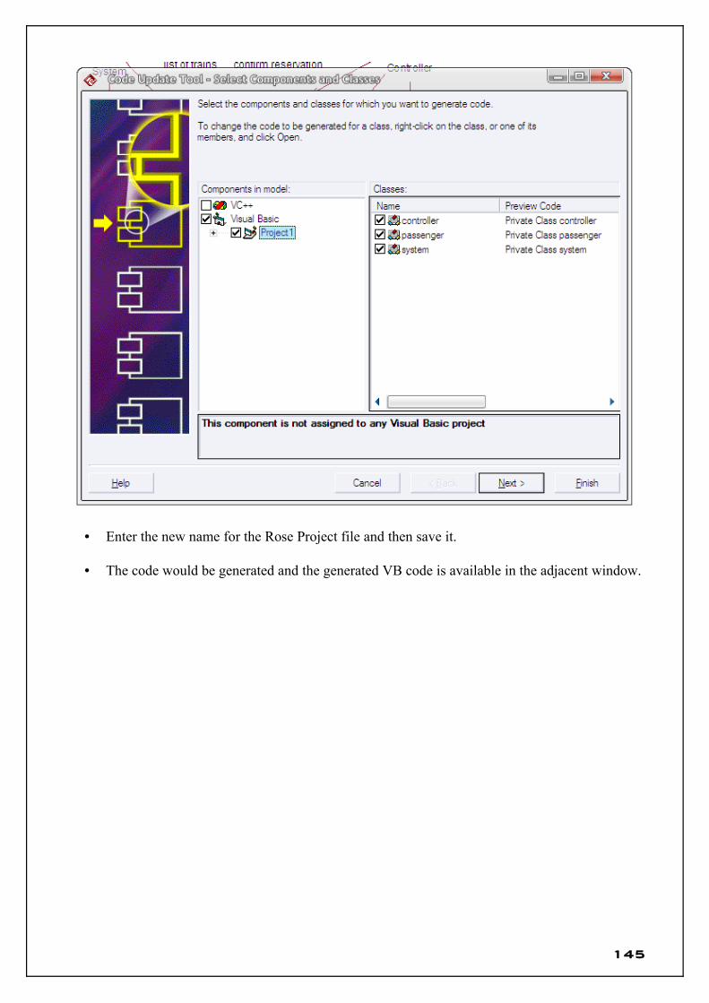
• Enter the new name for the Rose Project file and then save it.
• The code would be generated and the generated VB code is available in the adjacent window.
145

V i s u a l C + +
• Select the following from tools menu
• Component assignment tool opens up
• Drag the desired classes to the Visual Basic icon.
146

• Select yes and continue to select Project.
• Select OK.
147

• Select a project type (Win32) and enter project name. Select OK , then Finish and then OK.
• Select OK.
• Now right click the newly created component in the Component View and select as follows.
148

• The code would be generated and the generated VC++ code is available in the adjacent window.
149