Embed Size (px)
Citation preview

OOIINNTT0033DD OOwwnneerrrsquorsquoss MMaannuuaall
Rev12 (April 2012) 1
ONSIP
OINT03D
OOIINNTT0033DD OOwwnneerrrsquorsquoss MMaannuuaall
Rev12 (April 2012) 2
Note
This equipment has been tested and found to comply with the limits for a Class a digital device
pursuant to part 15 of the FCC Rules These limits are designed to provide reasonable protection
against harmful interference in a residential installation This equipment generate uses and can
radiate radio frequency energy and if not installed and used in accordance with the instructions may
cause harmful interference to radio communications However there is no guarantee that interference
will not occur in a particular installation If this equipment does cause harmful interference to radio or
television reception which can be determined by turning the equipment off and on the user is
encouraged to try to correct the interference by one or more of the following measures
Reorient or relocate the receiving antenna
Increase the separation between the equipment and receiver
Connect the equipment into and outlet on a circuit different from that to which the receiver is
connected
Consult the dealer or an experienced radioTV technician for help
Directions
Be careful not to cause any physical damage by dropping or throwing OINT03D Especially keep the device
out of reach from children
Do not disassemble OINT03D No After Service is assumed when disassembled
Use only the power adapter provided with OINT03D
Be careful to prevent moisture or water penetration into the unit Particular attention is needed when
installing OINT03D The screw holes for the installation screws and pipe should be maintained water tight
during the whole life time of the product
All the electrical connection wires running into the unit should be prepared so that water from the outside
cannot flow into the unit through the surface of the wires Penetration of the moisture through the wire for
extended period can cause malfunction of the unit or deteriorated image
OOIINNTT0033DD OOwwnneerrrsquorsquoss MMaannuuaall
Rev12 (April 2012) 3
Revision History
Date Revision Details
2011-11-01 10 First manual revision creation
2012-04-20 12
Caution
Any changes or modifications to this device could void the warranty
OOIINNTT0033DD OOwwnneerrrsquorsquoss MMaannuuaall
Rev12 (April 2012) 4
Contents
Contents 4
1 Introduction 6
11 Overview 6
12 Specification 7
13 Applications of OINT03D 9
2 Product Description 10
21 Contents 10
22 Product Preview 11
23 Physical description 12
24 Functional Description 14
25 Accessories for installation 16
3 On Site Installation 17
31 Bracket 17
4 Getting Started 18
41 PC Requirement 18
42 Quick Installation Guide 19
5 Trouble Shooting 25
51 No power is applied 25
52 Cannot connect to the Video 26
53 Windows Vista or Windows 7 27
54 Technical Assistance 30
6 Appendix - OSD menu control 31
6-1 OSD 33
6-2 Preset Mode 33
6-3 Menu Setup 33
OOIINNTT0033DD OOwwnneerrrsquorsquoss MMaannuuaall
Rev12 (April 2012) 5
6-4 Lens Setting 35
6-5 Exposure Setting 36
6-6 White Balance (White Bal) Setting 38
6-7 WDR Setting 39
6-8 Backlight Setting 40
6-9 SPECO DNR Setting 42
6-10 DayNight Setting 43
6-11 Special Setting 45
6-12 RETURN Setting 50
OOIINNTT0033DD OOwwnneerrrsquorsquoss MMaannuuaall
Rev12 (April 2012) 6
1 Introduction
11 Overview
The OINT03D is multi-codec (H264 MJPEG) IP camera (or network camera) built with embedded software and
hardware technology It enables real time transmission of synchronized video of up to D1 and audio data
Remote clients can connect to OINT03D for the real time videoaudio data through various client solutions
running on PC or smart device Real time 2-way communication is available through bidirectional audio
communication feature
Designed to be a stand-alone streaming audio amp video transmission device OINT03D can be applied to various
application area such as video security remote video monitoring distance education video conference or
internet broadcasting system
Vandal proof housing satisfying IP-67 will extend the application area to harsh environment of wide temperature
range
OOIINNTT0033DD OOwwnneerrrsquorsquoss MMaannuuaall
Rev12 (April 2012) 7
12 Specification
Category Sub-Category Details
Video Compression H264 MJPEG
Resolution Refer to the datasheet
Camera Module Mounting Gimbal 3 Axis Gimbal
Audio
(Bi-directional)
Up 32 Kbps G726
Down 128 Kbps PCM
Network
Interface RJ-45 10100 Mbps
Access network Static DHCP PPPPPPoE uPnP
Application RTP RTSP SMTP FTP HTTP SDP NTP DNS
IO
Sensor In 1 NC NO Selectable
Relay Output 0 NA
RS-232C NA
MicLine In Selectable in Admin page
Line Out 1 V p-p output for amplified speaker
CVBS output For temporal use in installation
Power Supply PoE NA
DC Adaptor 12V DC adaptor (15 Amp) - option
Housing IP67 compliant Vandal Proof housing
Mounting Bracket Mounting Wall Ceiling
Motion Detection 3 zones Arbitrary shape with independent sensitivity
Upgrade Firmware upgrade over IP network
Administration Remote administration over IP network
Client amp Viewer Web Viewer Simple viewing over internet explorer
Speco-NVR Standard CMS software
Dynamic IP support DDNS support Supported
Security VideoAudio stream encryption
OOIINNTT0033DD OOwwnneerrrsquorsquoss MMaannuuaall
Rev12 (April 2012) 8
ID and Password protection
IP filtering for restricting administrative
access for audio and bi-audio
Time management
Sync to PC Synchronize to PC
Manual Manual time setting
Internet Time Server Synchronize to Time Server
SDK support
Active-X
HTTP
Source filter
OOIINNTT0033DD OOwwnneerrrsquorsquoss MMaannuuaall
Rev12 (April 2012) 9
13 Applications of OINT03D
Security surveillance (buildings stores manufacturing facilities parking lots banks government facilities
military etc)
Remote monitoring (hospitals kindergartens traffic public areas etc)
Teleconference (Bi-directional audio conference) Remote Learning Internet broadcasting
Weather and environmental observation
OOIINNTT0033DD OOwwnneerrrsquorsquoss MMaannuuaall
Rev12 (April 2012) 10
2 Product Description
21 Contents
The product package contains followings
Contents Description Remarks
OINT03D IP camera OINT03D main unit
Power Adaptor 12VDC Adaptor (option)
Tools and Mounting Screws Screws L-type wrench
CD Software amp Userrsquos Guide
Quick Reference Guide Quick installation guide
OOIINNTT0033DD OOwwnneerrrsquorsquoss MMaannuuaall
Rev12 (April 2012) 11
22 Product Preview
OINT03D IP-Installer CMS Software
(NVR)
Weather proof
Bullet IP Camera
PC software to allocate an IP
address to the IP Camera
PC software to view and record
the AV streaming data transmitted
from IP camera
(Simultaneous support of up to 64
IP cameras)
OOIINNTT0033DD OOwwnneerrrsquorsquoss MMaannuuaall
Rev12 (April 2012) 12
23 Physical description
231 External View
Figure 2-1 External view of OINT03D
232 Connector information
Figure 2-2 Connector information
Audio-In
LAN Power
Sensor-In
Audio-Out
OOIINNTT0033DD OOwwnneerrrsquorsquoss MMaannuuaall
Rev12 (April 2012) 13
Figure 2-3 Factory Default switch and Video output connector
Focus control OSD control
Factory default
OOIINNTT0033DD OOwwnneerrrsquorsquoss MMaannuuaall
Rev12 (April 2012) 14
24 Functional Description
DC 12V(option) Power input for supplying 12V DC power
MICLINE IN
Connect external audio source or microphone
Line Out
Connect speakers with built in amplifier Audio from remote site is output through Line out in bi-directional
audio mode
100Base-T
100Mbps Ethernet connector (RJ-45)
Alarm InOut and Audio In
Used for connecting alarm sensor microphone and speaker to OINT03D
Description
LINE OUT (+) 1 V p-p audio signal output for amplified speaker
MICLINE GND (-) Ground for audio signals
MICLINE IN (+) Audio input Can be used either for microphone or applying audio
signals from other audio equipment
SENSOR IN Sensor In (+) NCNO selectable in admin mode
SENSOR IN GND Ground for sensor
SENSOR IN
Connect external alarm sensor Examples of sensing devices are infrared sensor motion sensor
heatsmoke sensor magnetic sensor etc Connect the two wires of the sensors to ldquoSNS Inrdquo The
sensor type (NCNO) can be set in admin page 10 mA can be flown into sensor device Multiple sensor
devices can be connected in parallel
OOIINNTT0033DD OOwwnneerrrsquorsquoss MMaannuuaall
Rev12 (April 2012) 15
SensorDevice
SensorPowerSupply
NONCType
Sensor1-
Sensor1+
+12VGND
Sensor Device
SensorPowerSupply
Open CollectorTypePhoto Coupler
Figure 2-4 SENSOR input and connection of the sensor
Factory Default Switch
A switch provided for returning the IP camera to factory default state Open the dome cover to access
the switch Press the switch for a few seconds while power is applied
Figure 2-5 Factory Default Switch
Factory default
OOIINNTT0033DD OOwwnneerrrsquorsquoss MMaannuuaall
Rev12 (April 2012) 16
25 Accessories for installation
Figure 2-6 Accessories for installation of OINT03D
OOIINNTT0033DD OOwwnneerrrsquorsquoss MMaannuuaall
Rev12 (April 2012) 17
3 On Site Installation
Use Cables and conduits that are suitable for the installation and that are compliant to IP-67 Particular attention
should be paid in the installation so that no moisture is allowed to penetrate into the unit through the cables or
conduits during the life time of the product Products of which the internal parts are exposed to moisture
because of improper installation are not covered by warranty
31 Bracket
Figure 2-7 Bracket installation
1 Make a suitable hole for cabling
2 Connect the cables
3 Fix the Base on the wall
4 Adjust the position of the lens for desired viewing of the site
5 Adjust the focus
OOIINNTT0033DD OOwwnneerrrsquorsquoss MMaannuuaall
Rev12 (April 2012) 18
4 Getting Started
Brief information for first time operation of OINT03D is provided in this chapter
41 PC Requirement
AudioVideo streaming data received from OINT03D can be displayed or stored in a PC running client programs
Minimum requirement of the PC is described below
Recommended Remark
CPU Pentium IV 3G above
Main Memory 1GB above
Operating System Windows XP
Web Browser Internet Explorer 60 above
Graphic Card 64M above Higher than 1600x1200
Network 100 Base-T Ethernet
Operating Systems supported Windows 2000 Professional Windows XP Vista 7
OOIINNTT0033DD OOwwnneerrrsquorsquoss MMaannuuaall
Rev12 (April 2012) 19
42 Quick Installation Guide
1 Connect PC and OINT03D to network
1) Prepare a PC to run programs for the installation and video connection
(PC is needed to assign IP address to OINT03D)
2) Connect OINT03D as shown in dotted line in Figure 4-1 The DC power is applied through DC adaptor
Figure 4-1 Power and network connection
LAN switch
DC adaptor
OOIINNTT0033DD OOwwnneerrrsquorsquoss MMaannuuaall
Rev12 (April 2012) 20
2 Install Speco-NVR
Speco-NVR is a multi-channel CMS program for to IP camera or Video server Install Speco-NVR on remote PC
to connect to these products It is needed to assign connection information to Speco-NVR program before
connection
Insert the CD provided with product into the PC and install the Speco-NVR
Figure 4-2 Speco-NVR
Follow the sequence below for setting the IP parameter
i) Run IP installer
ii) Click ① in IP installer windowgt Double click on ② gt Fill in ④ gt make a selection in ⑤ gt Fill the
parameters in ⑥
iii) Click on ⑨ to apply the settings
iv) You can connect to admin page by clicking on ⑩
Admin Page Button
IP installer
OOIINNTT0033DD OOwwnneerrrsquorsquoss MMaannuuaall
Rev12 (April 2012) 21
Click on the field in ③ for sorting and rearranging the list
Select network mode that best suits from the drop down list in ⑤ You can choose either
Static or ADSL and Auto (DHCP) respectively If ADSL and Auto are selected the fields in ⑥
is deactivated
In case of ADSL fill the User Name and Password in ⑧ with the values provided by your ISP
If DDNS service is needed Check at the box and fill the empty field with hostname you want
in ⑦
1
2
3
6
4
9
5
7
8
10
OOIINNTT0033DD OOwwnneerrrsquorsquoss MMaannuuaall
Rev12 (April 2012) 22
3 Remote video connection to OINT03D
1) Connection through Web Viewer
Web Viewer offers simplest way of video connection to OINT03D For video connection enter the IP
address of OINT03D in the URL window of Internet Explorer as
Note Active-X module should be installed on your PC before actual connection If your PC is
not connected to the internet you cannot download Active-X module Most convenient way of
installing the Active-X module is installing Speco-NVR which is available from the CD or our
web site
Figure 4-3 Web Viewer
Default ID and password of Admin Page are admin 1234 For more detailed information please refer to the
[Configuration_Guide] Guide
Connection to Admin Page
Basic Control Buttons
Video Crop Control
[eg] Port 8080
[eg] Port 80 Can be omitted the default
port of 80
OOIINNTT0033DD OOwwnneerrrsquorsquoss MMaannuuaall
Rev12 (April 2012) 23
2) Connection through Speco-NVR
Click the camera assignment button for setting camera address Input the description address Ch
User ID Password and port and then click the save button After assignment procedure you must
click the SAVE button You can see the live video when you click the live view button as below When
you exit Speco-NVR you have to input the IDPW admin1234 Details for the Speco-NVR can be
found in [Speco-NVR Userrsquos Guide]
Figure 4-4 Speco-NVR
Camera Assignment
Camera Assignment
Live view
Save
Example
Exit Program
Default IDPW admin1234
OOIINNTT0033DD OOwwnneerrrsquorsquoss MMaannuuaall
Rev12 (April 2012) 24
4 Additional settings through connection to the Admin Page
All the parameters of new IP camera fallows factory default values For more sophisticated target application it
is needed to change parameters The admin page can be connected through
rdquohttpIP_addressHTTP_port_numberrdquoadminhtm
It is needed to enter ID and password of the administrator Default ID and password are admin 1234 It is
highly recommended to change the ID and password to prevent illegal access to the IP camera For more
detailed information please refer to the [Configuration_Guide] Guide
OOIINNTT0033DD OOwwnneerrrsquorsquoss MMaannuuaall
Rev12 (April 2012) 25
5 Trouble Shooting
51 No power is applied
In case of DC adaptor
If PoE is not applied the power and network connection should be made through separate cables
It is recommended to use DC adaptor supplied by provider for the feeding of the power In case of
replacing the DC power supply make sure that the power supply meets with the power
requirement of the IP camera to prevent damage or malfunction
OOIINNTT0033DD OOwwnneerrrsquorsquoss MMaannuuaall
Rev12 (April 2012) 26
52 Cannot connect to the Video
Check the status of the network connection through PING test
Try the following on your PC
- Start gt Run gt Cmd gt Ping IP address (Ex Ping 172164251)
- If ldquoReply from ~rdquo message is returned ( in the figure below) the network connection is in normal
state Try connection to the video again If the problem persists or refer to other trouble shooting notes
- If ldquoRequest timed outrdquo message is returned ( in the figure below) the network connection or
network setting is not in normal state Check the network cable and settings
1
2
1 2
OOIINNTT0033DD OOwwnneerrrsquorsquoss MMaannuuaall
Rev12 (April 2012) 27
53 Windows Vista or Windows 7
Windows Vista and Windows 7 users need to configure UAC (User Access Control) and Privilege Level for
proper recording and still video capture in Speco-NVR and Web Viewer
ltWindows Vistagt
1 UAC (User Access Control) configuration
1) Double-click ldquoUser Accountsrdquo in control panel
2) Double-click ldquoTurn User Account Control on or offrdquo
3) Uncheck ldquoUse UAC to help protect your computerrdquo
2 Privilege Level Control
1) Select ldquoNVRrdquo icon on the desktop
2) Click right mouse button and select ldquoPropertiesrdquo
3) Check ldquoPrivilege Levelrdquo in ldquoCompatibilityrdquo tab
OOIINNTT0033DD OOwwnneerrrsquorsquoss MMaannuuaall
Rev12 (April 2012) 28
ltWindows 7gt
1 UAC (User Access Control) configuration
1) Double-click ldquoUser Accountsrdquo in control panel
2) Double-click ldquoChange User Account Control settingrdquo
3) Set to ldquoNever notifyrdquo
OOIINNTT0033DD OOwwnneerrrsquorsquoss MMaannuuaall
Rev12 (April 2012) 29
2 Privilege Level Control
1) Select ldquoNVRrdquo icon on the desktop
2) Click right mouse button and select ldquopropertiesrdquo
3) Check ldquoPrivilege Levelrdquo in ldquoCompatibilityrdquo tab
OOIINNTT0033DD OOwwnneerrrsquorsquoss MMaannuuaall
Rev12 (April 2012) 30
54 Technical Assistance
If you need any technical assistance please contact your dealer For immediate service please provide the
following information
1 Model name
2 MAC address and Registration number
3 Purchase date
4 Description of the problem
5 Error message
OOIINNTT0033DD OOwwnneerrrsquorsquoss MMaannuuaall
Rev12 (April 2012) 31
6 Appendix - OSD menu control
To control OSD menu there are two methods
First is Video setup page in Administration Tool using Internet Browser as below
OOIINNTT0033DD OOwwnneerrrsquorsquoss MMaannuuaall
Rev12 (April 2012) 32
Scond is OSD menu controller on camera as below
OOIINNTT0033DD OOwwnneerrrsquorsquoss MMaannuuaall
Rev12 (April 2012) 33
6-1 OSD
All camera functions are menu driven for easy use
6-2 Preset Mode
1 Preset INDOOR OUTDOOR LOW LIGHT HALLWAY LOBBY ELEVATOR
- Used for a quick and easy setup for the installation environment
6-3 Menu Setup
1 Press the Function Setup switch
- Main setup menu is displayed on the monitor screen
2 Select a desired function using the Function Setup switch
- Place the cursor over a desired item
3 Set up a selected item by using the Function Setup switch
OOIINNTT0033DD OOwwnneerrrsquorsquoss MMaannuuaall
Rev12 (April 2012) 34
4 To finish the setting select RETURN and press the Function Setup switch
NOTE
An item with the icon also has sub menus To select a sub menu select an item with the icon and press
the Function Setup switch
An item with the - - - icon is unavailable due to function settings
OOIINNTT0033DD OOwwnneerrrsquorsquoss MMaannuuaall
Rev12 (April 2012) 35
6-4 Lens Setting
Using this function you can control the screen brightness
1 When the SETUP menu screen is displayed select LENS by using the Function Setup switch so that
the arrow indicates LENS
2 DC You can adjust the minimum shutter and maximum value of ESC shutter mode
NOTE
If color rolling occurs when using a DC lens set Shutter to Fixed (---)
OOIINNTT0033DD OOwwnneerrrsquorsquoss MMaannuuaall
Rev12 (April 2012) 36
6-5 Exposure Setting
1 When the SETUP menu screen is displayed select EXPOSURE by using the Function Setup Switch
2 Select a desired mode using the Function Setup switch
SHUTTER You can select either auto or manual shutter
--- Shutter speed is fixed at 160sec(150sec)
ESC Select this to control the shutter speed automatically If ESC is selected the shutter speed is
automatically controlled depending on the ambient illumination of the subject
MANUAL You can control shutter speed manually
(NTSC MODEL 160~1120000 PAL MODEL 150~1120000)
AFLK Select this when you see picture flicker this can happen when the frequency of the local
lighting clashes with the camera
NOTE
When the SHUTTER is set to MANUAL or AFLK mode INTENSIFY will be disabled
AGC(AUTO GAIN CONTROL) The higher the gain level the brighter the screen
- but the higher the noise
OFF Deactivates the AGC function
OOIINNTT0033DD OOwwnneerrrsquorsquoss MMaannuuaall
Rev12 (April 2012) 37
LOW Allows automatic gain control from 53dB to 32dB
HIGH Allows automatic gain control from 53dB to 37dB
INTENSIFY When it is night or dark the camera automatically detects then light level and
maintains a clear picture if this mode is activated
OFF Deactivates the INTENSIFY function
AUTO Activates the INTENSIFY function
RETURN Select this to save the changes in the EXPOSURE menu and return to the SETUP menu
NOTE
If you press the Function Setup switch to lsquoAUTOrsquo mode you can adjust brightness by increasing or
decreasing the shutter speed (x2 ~ x512)
Note that the higher the zoom level the brighter the screen but the more likely there will be a ghosting
effect
It is normal for Noise Spots and Whitish symptoms to appear in INTENSIFY mode when the D-ZOOM level
is increased
OOIINNTT0033DD OOwwnneerrrsquorsquoss MMaannuuaall
Rev12 (April 2012) 38
6-6 White Balance (White Bal) Setting
Use the White Balance function to adjust the screen color
1 When the SETUP menu screen is displayed select White Bal by using the function Setup switch so that
the arrow indicates White Bal
2 Select a desired mode using the Function Setup switch
Select one of the following 5 modes as appropriate for your purpose
ATW Select this when the color temperature is between 1700˚K and 11000˚K
OUTDOOR Select this when the color temperature is between 1700˚K and 11000˚K (sodium light
inclusion)
INDOOR Select this when the color temperature is between 4500˚K and 8500˚K
MANUAL Select this to fine-tune White Balance manually Set White Balance first by using the
ATW or AWC mode After that switch to MANUAL mode fine-tune the White Balance and then press
the Function Setup switch
AWCrarrSET To find the optimal luminance level for the current environment point the camera
towards a sheet of white paper and press the Function Setup switch If the environment changes
readjust it
NOTE
White Balance may not work properly under the following conditions In this case select the AWC mode
① When the color temperature of the environment surrounding the subject is out of the control range (eg
clear sky or sunset)
② When the ambient illumination of the subject is dim
③ If the camera is directed towards a fluorescent light or is installed in a place where illumination changes
dramatically the White Balance operation may become unstable
OOIINNTT0033DD OOwwnneerrrsquorsquoss MMaannuuaall
Rev12 (April 2012) 39
6-7 WDR Setting
WDR illuminates darker spots of an image while retaining the same light level for brighter spots to even out the
overall brightness of images with high contrast between bright and dark spots
1 When the SETUP menu screen is displayed select WDR by using the switch so that the arrow
indicates WDR
2 Use the switch to change the WDR level according to the contrast between bright and dark areas9
OOIINNTT0033DD OOwwnneerrrsquorsquoss MMaannuuaall
Rev12 (April 2012) 40
6-8 Backlight Setting
Unlike conventional cameras the 650Line Intensifier3trade Series are designed to deliver a distinctive subject and
background at the same time even when the subject is backlight by using the features of the proprietary W-V
DSP chip
1 When the SETUP menu screen is displayed select BACKLIGHT by using the Function Setup switch so
that the arrow indicates BACKLIGHT
2 Select a desired mode using the Function Setup switch
BLC Enables a user to directly select a desired area from a picture and to view the area more
clearly
HLC (High Light Compensation) If the scene contains extremely bright light areas such as from
car headlights the light can mask out much of the on-screen detail
- LEVEL Adjust level of the HLC function
- LIMIT Enable to change the operating condition
- MASK COLORTONE Change the color transparency of the masking area
(Black Red Blue Cyan Magenta)
- TOPBOTTOMLEFTRIGHT Adjust the area to be enhanced
OFF Not being used
3 Select a desired mode using the Function Setup switch and press the Function Setup switch
Select BLC to adjust the area to be enhanced then adjust the level
OOIINNTT0033DD OOwwnneerrrsquorsquoss MMaannuuaall
Rev12 (April 2012) 41
NOTE
Because there can be a difference in the effectiveness of HLC according to the amount of light area in the
screen optimize the installation angle for the best HLC performance
When dark the HLC is only activated when a bright light exceeding a specific size in NIGHT ONLY mode
The HLC is not activated in day light or when bright light is not present at night in NIGHT ONLY mode
BLC Function doesnt work in the BW mode of the DAYNIGHT menu
OOIINNTT0033DD OOwwnneerrrsquorsquoss MMaannuuaall
Rev12 (April 2012) 42
6-9 SPECO DNR Setting
This function reduces the background noise in a low luminance environment
1 When the SETUP menu screen is displayed select SPECO DNR by using the Function Setup switch
so that the arrow indicates SPECO DNR
2 Select a desired mode using the Function Setup switch
OFF Deactivates SPECO DNR Noise is not reduced
ON Activates SPECO DNR so that noise is reduced
3 Set the SPECO DNR mode to ON and press the Function Setup switch Then you can adjust the noise
reduction level
NOTE
You cannot set the SPECO DNR to lsquoONrsquo or lsquoOFFrsquo when the AGC mode of the EXPOSURE menu is
lsquoOFFrsquo
When adjusting the noise reduction level in the SPECO DNR mode remember that the higher the level set
the more the noise level will be reduced as will the brightness of the image
OOIINNTT0033DD OOwwnneerrrsquorsquoss MMaannuuaall
Rev12 (April 2012) 43
6-10 DayNight Setting
You can display pictures in color or black and white
1 When the SETUP menu screen is displayed select DAYNIGHTby using the Function Setup switch so
that the arrow indicates DAYNIGHT
2 Select a desired mode using the Function Setup Switch according to the picture display you want
COLOR The picture is always displayed in color
BW The picture is always displayed in black and white
- BURST MODE You can turn on or off the burst signal on BW mode
AUTO The mode is switched to Color in a normal environment but switches to BW mode when
ambient illumination is low To set up the switching time for AUTO mode press the Function Setup
switch You can turn on or off the burst signal on BW mode
OOIINNTT0033DD OOwwnneerrrsquorsquoss MMaannuuaall
Rev12 (April 2012) 44
- BURST MODE You can turn on or off the burst signal on BW mode
- DURATION You can select brightness of illumination about changing the daynight mode
- DWELLTIME You can select the duration time about changing the daynight mode
rarr3s 5s 7s 10s 15s 20s 30s 40 60s
The daynight switching point of the camera can be adjusted
NOTE
When AGC in the EXPOSURE menu is OFF --- mode operates as like selecting COLOR mode and
AUTO mode can not be selected
OOIINNTT0033DD OOwwnneerrrsquorsquoss MMaannuuaall
Rev12 (April 2012) 45
6-11 Special Setting
1 When the SETUP menu screen is displayed select SPECIAL by using the Function Setup switch so
that the arrow indicates SPECIAL
2 Select a desired mode using the Function Setup switch
OOIINNTT0033DD OOwwnneerrrsquorsquoss MMaannuuaall
Rev12 (April 2012) 46
IMAGE ADJ
1) When the SETUP menu screen is displayed select IMAGE ADJ by using the Function Setup switch
so that the arrow indicates IMAGE ADJ
2) Select a desired mode using the Function Setup switch
V-REV You can flip the picture vertically on the screen
H-REV You can flip the picture horizontally on the screen
D-ZOOM You can use a digital zoom of x1 ~ x16
DIS (Digital Image Stabilizer) This function mitigates any picture movement due to external factors
such as wind
FONT COLOR You can change the OSD font color (White Yellow Green Red Blue)
SHARPNESS As you increase this value the picture outline becomes stronger and clearer Adjust
this value appropriately depending on the sharpness of the picture
RETURN Select this to save the settings for the IMAGE ADJ menu and to return to the SETUP menu
NOTE
When the V-REV or H-REV mode is enabled the text on the screen does not flip
If you increase the SHARPNESS level too high the picture may become distorted or noise
may appear
MONITOR Please change the settings value of video appropriate to your monitor
1) LCD Please select this menu item when using a LCD monitor
2) CRT Please select this menu item when using a CRT monitor
3) USER Please use this menu item when using a monitor other than standard ones You can change
the gamma PED level and color gain in the sub menus
OOIINNTT0033DD OOwwnneerrrsquorsquoss MMaannuuaall
Rev12 (April 2012) 47
CAM TITLE If you enter a title the title will appear on the monitor
1) If the SPECIAL menu screen is displayed use the Function Setup switch so that the arrow indicates
CAM TITLE
2) Set it to ON by using the Function Setup switch
3) Press the Function Setup switch
4) Use the Function Setup switch to move to a desired letter and select the letter by pressing the
Function Setup switch Repeat this to enter multiple letters You can enter up to 15 letters
5) Enter a title move the cursor to POS and press the Function Setup switch The entered title
appears on the screen Select the position to display the title on the screen by using the Function Setup
switch and press the Function Setup switch When the position is determined select END and press
the Function Setup switch to return to the SPECIAL menu
OOIINNTT0033DD OOwwnneerrrsquorsquoss MMaannuuaall
Rev12 (April 2012) 48
NOTE
When the CAM TITLE menu is lsquoOFFrsquo no title will be displayed on the monitor screen even if you enter one
Only English is available in this mode
If you move the cursor to CLR and press the Function Setup switch all the letters are deleted To edit a
letter change the cursor to the bottom left arrow and press the Function Setup switch Move the cursor over the
letter to be edited move the cursor to the letter to be inserted and then press the Function Setup switch
SYNC In areas where the supply is at 60Hz(NTSC) 50Hz(PAL) you can synchronize the output
phase of multiple cameras using the power synchronization function (Line-Lock) without using a
synchronization signal generator
- INT Internal Synchronization Type
- LL Power Synchronization Type Line-lock
Press the Function Setup switch
You can select a desired phase from 0 to 359 when select phase
NOTE
When using AC power at 60Hz(NTSC) 50Hz(PAL) frequency you can use the LL type synchronization
When the power is DC 12V the SYNC menu is fixed to the lsquoINTrsquo mode
MOTION DET This product has a feature that allows you to observe movement of objects in 8
different areas on the screen and the words MOTION DETECTED appear on the screen when
movement is detected Activity can be monitor more efficiently
1) When the SPECIAL menu screen is displayed press the Function Setup switch so that the arrow
OOIINNTT0033DD OOwwnneerrrsquorsquoss MMaannuuaall
Rev12 (April 2012) 49
indicates lsquoMOTION DETrsquo
2) Set up the mode using the Function Setup switch
- SENSITIVITY You can select up to 8 MD areas When SENSITIVITY number is high motion
detection sensitivity is increased to recognize even small movement
- AREA MODE Determines whether to use the MD area selected in SENSITIVITY
- SEL POS Determines which of the 4 vertices of each MD area is to be used
- XPOS Determines the coordinate of the horizontal axis for SEL POS
- YPOS Determines the coordinate of the vertical axis for SEL POS
- FILLrarrSET Fills in a selected MD area The color of the area can be selected from brown orange
blue cyan green yellow magenta and red
- RETURN Select this to save the MOTION DET menu settings and return to the SPECIAL menu
PRIVACY Mask an area you want to hide on the screen
1) When the SPECIAL menu screen is displayed press the Function Setup switch so that the arrow
indicates PRIVACY
2) Set up the mode using the Function Setup switch
- AREA You can select up to 12 PRIVACY areas
- MODE Determines whether to use the area selected in the AREA
- MASK COLOR Determine area color You can select Green Red Blue Black White and Gray
- MASK TONE Adjust the brightness of MASK COLOR
- TOPBOTTOMLEFTRIGHT Adjust the size and position of the selected area
- RETURN Select this to save the PRIVACY menu settings and return to the SPECIAL menu
OOIINNTT0033DD OOwwnneerrrsquorsquoss MMaannuuaall
Rev12 (April 2012) 50
6-12 RETURN Setting
Select a desired RETURN mode using the Function Setup Switch
- SAVE Save the current settings and RETURN the MAIN SETUP menu
- NOT SAVE Do not save the current settings and RETURN the MAIN SETUP menu
- RESET Resets the camera settings to the factory defaults Language Communication and Monitor
Settings are not initialized

OOIINNTT0033DD OOwwnneerrrsquorsquoss MMaannuuaall
Rev12 (April 2012) 3
Revision History
Date Revision Details
2011-11-01 10 First manual revision creation
2012-04-20 12
Caution
Any changes or modifications to this device could void the warranty
OOIINNTT0033DD OOwwnneerrrsquorsquoss MMaannuuaall
Rev12 (April 2012) 4
Contents
Contents 4
1 Introduction 6
11 Overview 6
12 Specification 7
13 Applications of OINT03D 9
2 Product Description 10
21 Contents 10
22 Product Preview 11
23 Physical description 12
24 Functional Description 14
25 Accessories for installation 16
3 On Site Installation 17
31 Bracket 17
4 Getting Started 18
41 PC Requirement 18
42 Quick Installation Guide 19
5 Trouble Shooting 25
51 No power is applied 25
52 Cannot connect to the Video 26
53 Windows Vista or Windows 7 27
54 Technical Assistance 30
6 Appendix - OSD menu control 31
6-1 OSD 33
6-2 Preset Mode 33
6-3 Menu Setup 33
OOIINNTT0033DD OOwwnneerrrsquorsquoss MMaannuuaall
Rev12 (April 2012) 5
6-4 Lens Setting 35
6-5 Exposure Setting 36
6-6 White Balance (White Bal) Setting 38
6-7 WDR Setting 39
6-8 Backlight Setting 40
6-9 SPECO DNR Setting 42
6-10 DayNight Setting 43
6-11 Special Setting 45
6-12 RETURN Setting 50
OOIINNTT0033DD OOwwnneerrrsquorsquoss MMaannuuaall
Rev12 (April 2012) 6
1 Introduction
11 Overview
The OINT03D is multi-codec (H264 MJPEG) IP camera (or network camera) built with embedded software and
hardware technology It enables real time transmission of synchronized video of up to D1 and audio data
Remote clients can connect to OINT03D for the real time videoaudio data through various client solutions
running on PC or smart device Real time 2-way communication is available through bidirectional audio
communication feature
Designed to be a stand-alone streaming audio amp video transmission device OINT03D can be applied to various
application area such as video security remote video monitoring distance education video conference or
internet broadcasting system
Vandal proof housing satisfying IP-67 will extend the application area to harsh environment of wide temperature
range
OOIINNTT0033DD OOwwnneerrrsquorsquoss MMaannuuaall
Rev12 (April 2012) 7
12 Specification
Category Sub-Category Details
Video Compression H264 MJPEG
Resolution Refer to the datasheet
Camera Module Mounting Gimbal 3 Axis Gimbal
Audio
(Bi-directional)
Up 32 Kbps G726
Down 128 Kbps PCM
Network
Interface RJ-45 10100 Mbps
Access network Static DHCP PPPPPPoE uPnP
Application RTP RTSP SMTP FTP HTTP SDP NTP DNS
IO
Sensor In 1 NC NO Selectable
Relay Output 0 NA
RS-232C NA
MicLine In Selectable in Admin page
Line Out 1 V p-p output for amplified speaker
CVBS output For temporal use in installation
Power Supply PoE NA
DC Adaptor 12V DC adaptor (15 Amp) - option
Housing IP67 compliant Vandal Proof housing
Mounting Bracket Mounting Wall Ceiling
Motion Detection 3 zones Arbitrary shape with independent sensitivity
Upgrade Firmware upgrade over IP network
Administration Remote administration over IP network
Client amp Viewer Web Viewer Simple viewing over internet explorer
Speco-NVR Standard CMS software
Dynamic IP support DDNS support Supported
Security VideoAudio stream encryption
OOIINNTT0033DD OOwwnneerrrsquorsquoss MMaannuuaall
Rev12 (April 2012) 8
ID and Password protection
IP filtering for restricting administrative
access for audio and bi-audio
Time management
Sync to PC Synchronize to PC
Manual Manual time setting
Internet Time Server Synchronize to Time Server
SDK support
Active-X
HTTP
Source filter
OOIINNTT0033DD OOwwnneerrrsquorsquoss MMaannuuaall
Rev12 (April 2012) 9
13 Applications of OINT03D
Security surveillance (buildings stores manufacturing facilities parking lots banks government facilities
military etc)
Remote monitoring (hospitals kindergartens traffic public areas etc)
Teleconference (Bi-directional audio conference) Remote Learning Internet broadcasting
Weather and environmental observation
OOIINNTT0033DD OOwwnneerrrsquorsquoss MMaannuuaall
Rev12 (April 2012) 10
2 Product Description
21 Contents
The product package contains followings
Contents Description Remarks
OINT03D IP camera OINT03D main unit
Power Adaptor 12VDC Adaptor (option)
Tools and Mounting Screws Screws L-type wrench
CD Software amp Userrsquos Guide
Quick Reference Guide Quick installation guide
OOIINNTT0033DD OOwwnneerrrsquorsquoss MMaannuuaall
Rev12 (April 2012) 11
22 Product Preview
OINT03D IP-Installer CMS Software
(NVR)
Weather proof
Bullet IP Camera
PC software to allocate an IP
address to the IP Camera
PC software to view and record
the AV streaming data transmitted
from IP camera
(Simultaneous support of up to 64
IP cameras)
OOIINNTT0033DD OOwwnneerrrsquorsquoss MMaannuuaall
Rev12 (April 2012) 12
23 Physical description
231 External View
Figure 2-1 External view of OINT03D
232 Connector information
Figure 2-2 Connector information
Audio-In
LAN Power
Sensor-In
Audio-Out
OOIINNTT0033DD OOwwnneerrrsquorsquoss MMaannuuaall
Rev12 (April 2012) 13
Figure 2-3 Factory Default switch and Video output connector
Focus control OSD control
Factory default
OOIINNTT0033DD OOwwnneerrrsquorsquoss MMaannuuaall
Rev12 (April 2012) 14
24 Functional Description
DC 12V(option) Power input for supplying 12V DC power
MICLINE IN
Connect external audio source or microphone
Line Out
Connect speakers with built in amplifier Audio from remote site is output through Line out in bi-directional
audio mode
100Base-T
100Mbps Ethernet connector (RJ-45)
Alarm InOut and Audio In
Used for connecting alarm sensor microphone and speaker to OINT03D
Description
LINE OUT (+) 1 V p-p audio signal output for amplified speaker
MICLINE GND (-) Ground for audio signals
MICLINE IN (+) Audio input Can be used either for microphone or applying audio
signals from other audio equipment
SENSOR IN Sensor In (+) NCNO selectable in admin mode
SENSOR IN GND Ground for sensor
SENSOR IN
Connect external alarm sensor Examples of sensing devices are infrared sensor motion sensor
heatsmoke sensor magnetic sensor etc Connect the two wires of the sensors to ldquoSNS Inrdquo The
sensor type (NCNO) can be set in admin page 10 mA can be flown into sensor device Multiple sensor
devices can be connected in parallel
OOIINNTT0033DD OOwwnneerrrsquorsquoss MMaannuuaall
Rev12 (April 2012) 15
SensorDevice
SensorPowerSupply
NONCType
Sensor1-
Sensor1+
+12VGND
Sensor Device
SensorPowerSupply
Open CollectorTypePhoto Coupler
Figure 2-4 SENSOR input and connection of the sensor
Factory Default Switch
A switch provided for returning the IP camera to factory default state Open the dome cover to access
the switch Press the switch for a few seconds while power is applied
Figure 2-5 Factory Default Switch
Factory default
OOIINNTT0033DD OOwwnneerrrsquorsquoss MMaannuuaall
Rev12 (April 2012) 16
25 Accessories for installation
Figure 2-6 Accessories for installation of OINT03D
OOIINNTT0033DD OOwwnneerrrsquorsquoss MMaannuuaall
Rev12 (April 2012) 17
3 On Site Installation
Use Cables and conduits that are suitable for the installation and that are compliant to IP-67 Particular attention
should be paid in the installation so that no moisture is allowed to penetrate into the unit through the cables or
conduits during the life time of the product Products of which the internal parts are exposed to moisture
because of improper installation are not covered by warranty
31 Bracket
Figure 2-7 Bracket installation
1 Make a suitable hole for cabling
2 Connect the cables
3 Fix the Base on the wall
4 Adjust the position of the lens for desired viewing of the site
5 Adjust the focus
OOIINNTT0033DD OOwwnneerrrsquorsquoss MMaannuuaall
Rev12 (April 2012) 18
4 Getting Started
Brief information for first time operation of OINT03D is provided in this chapter
41 PC Requirement
AudioVideo streaming data received from OINT03D can be displayed or stored in a PC running client programs
Minimum requirement of the PC is described below
Recommended Remark
CPU Pentium IV 3G above
Main Memory 1GB above
Operating System Windows XP
Web Browser Internet Explorer 60 above
Graphic Card 64M above Higher than 1600x1200
Network 100 Base-T Ethernet
Operating Systems supported Windows 2000 Professional Windows XP Vista 7
OOIINNTT0033DD OOwwnneerrrsquorsquoss MMaannuuaall
Rev12 (April 2012) 19
42 Quick Installation Guide
1 Connect PC and OINT03D to network
1) Prepare a PC to run programs for the installation and video connection
(PC is needed to assign IP address to OINT03D)
2) Connect OINT03D as shown in dotted line in Figure 4-1 The DC power is applied through DC adaptor
Figure 4-1 Power and network connection
LAN switch
DC adaptor
OOIINNTT0033DD OOwwnneerrrsquorsquoss MMaannuuaall
Rev12 (April 2012) 20
2 Install Speco-NVR
Speco-NVR is a multi-channel CMS program for to IP camera or Video server Install Speco-NVR on remote PC
to connect to these products It is needed to assign connection information to Speco-NVR program before
connection
Insert the CD provided with product into the PC and install the Speco-NVR
Figure 4-2 Speco-NVR
Follow the sequence below for setting the IP parameter
i) Run IP installer
ii) Click ① in IP installer windowgt Double click on ② gt Fill in ④ gt make a selection in ⑤ gt Fill the
parameters in ⑥
iii) Click on ⑨ to apply the settings
iv) You can connect to admin page by clicking on ⑩
Admin Page Button
IP installer
OOIINNTT0033DD OOwwnneerrrsquorsquoss MMaannuuaall
Rev12 (April 2012) 21
Click on the field in ③ for sorting and rearranging the list
Select network mode that best suits from the drop down list in ⑤ You can choose either
Static or ADSL and Auto (DHCP) respectively If ADSL and Auto are selected the fields in ⑥
is deactivated
In case of ADSL fill the User Name and Password in ⑧ with the values provided by your ISP
If DDNS service is needed Check at the box and fill the empty field with hostname you want
in ⑦
1
2
3
6
4
9
5
7
8
10
OOIINNTT0033DD OOwwnneerrrsquorsquoss MMaannuuaall
Rev12 (April 2012) 22
3 Remote video connection to OINT03D
1) Connection through Web Viewer
Web Viewer offers simplest way of video connection to OINT03D For video connection enter the IP
address of OINT03D in the URL window of Internet Explorer as
Note Active-X module should be installed on your PC before actual connection If your PC is
not connected to the internet you cannot download Active-X module Most convenient way of
installing the Active-X module is installing Speco-NVR which is available from the CD or our
web site
Figure 4-3 Web Viewer
Default ID and password of Admin Page are admin 1234 For more detailed information please refer to the
[Configuration_Guide] Guide
Connection to Admin Page
Basic Control Buttons
Video Crop Control
[eg] Port 8080
[eg] Port 80 Can be omitted the default
port of 80
OOIINNTT0033DD OOwwnneerrrsquorsquoss MMaannuuaall
Rev12 (April 2012) 23
2) Connection through Speco-NVR
Click the camera assignment button for setting camera address Input the description address Ch
User ID Password and port and then click the save button After assignment procedure you must
click the SAVE button You can see the live video when you click the live view button as below When
you exit Speco-NVR you have to input the IDPW admin1234 Details for the Speco-NVR can be
found in [Speco-NVR Userrsquos Guide]
Figure 4-4 Speco-NVR
Camera Assignment
Camera Assignment
Live view
Save
Example
Exit Program
Default IDPW admin1234
OOIINNTT0033DD OOwwnneerrrsquorsquoss MMaannuuaall
Rev12 (April 2012) 24
4 Additional settings through connection to the Admin Page
All the parameters of new IP camera fallows factory default values For more sophisticated target application it
is needed to change parameters The admin page can be connected through
rdquohttpIP_addressHTTP_port_numberrdquoadminhtm
It is needed to enter ID and password of the administrator Default ID and password are admin 1234 It is
highly recommended to change the ID and password to prevent illegal access to the IP camera For more
detailed information please refer to the [Configuration_Guide] Guide
OOIINNTT0033DD OOwwnneerrrsquorsquoss MMaannuuaall
Rev12 (April 2012) 25
5 Trouble Shooting
51 No power is applied
In case of DC adaptor
If PoE is not applied the power and network connection should be made through separate cables
It is recommended to use DC adaptor supplied by provider for the feeding of the power In case of
replacing the DC power supply make sure that the power supply meets with the power
requirement of the IP camera to prevent damage or malfunction
OOIINNTT0033DD OOwwnneerrrsquorsquoss MMaannuuaall
Rev12 (April 2012) 26
52 Cannot connect to the Video
Check the status of the network connection through PING test
Try the following on your PC
- Start gt Run gt Cmd gt Ping IP address (Ex Ping 172164251)
- If ldquoReply from ~rdquo message is returned ( in the figure below) the network connection is in normal
state Try connection to the video again If the problem persists or refer to other trouble shooting notes
- If ldquoRequest timed outrdquo message is returned ( in the figure below) the network connection or
network setting is not in normal state Check the network cable and settings
1
2
1 2
OOIINNTT0033DD OOwwnneerrrsquorsquoss MMaannuuaall
Rev12 (April 2012) 27
53 Windows Vista or Windows 7
Windows Vista and Windows 7 users need to configure UAC (User Access Control) and Privilege Level for
proper recording and still video capture in Speco-NVR and Web Viewer
ltWindows Vistagt
1 UAC (User Access Control) configuration
1) Double-click ldquoUser Accountsrdquo in control panel
2) Double-click ldquoTurn User Account Control on or offrdquo
3) Uncheck ldquoUse UAC to help protect your computerrdquo
2 Privilege Level Control
1) Select ldquoNVRrdquo icon on the desktop
2) Click right mouse button and select ldquoPropertiesrdquo
3) Check ldquoPrivilege Levelrdquo in ldquoCompatibilityrdquo tab
OOIINNTT0033DD OOwwnneerrrsquorsquoss MMaannuuaall
Rev12 (April 2012) 28
ltWindows 7gt
1 UAC (User Access Control) configuration
1) Double-click ldquoUser Accountsrdquo in control panel
2) Double-click ldquoChange User Account Control settingrdquo
3) Set to ldquoNever notifyrdquo
OOIINNTT0033DD OOwwnneerrrsquorsquoss MMaannuuaall
Rev12 (April 2012) 29
2 Privilege Level Control
1) Select ldquoNVRrdquo icon on the desktop
2) Click right mouse button and select ldquopropertiesrdquo
3) Check ldquoPrivilege Levelrdquo in ldquoCompatibilityrdquo tab
OOIINNTT0033DD OOwwnneerrrsquorsquoss MMaannuuaall
Rev12 (April 2012) 30
54 Technical Assistance
If you need any technical assistance please contact your dealer For immediate service please provide the
following information
1 Model name
2 MAC address and Registration number
3 Purchase date
4 Description of the problem
5 Error message
OOIINNTT0033DD OOwwnneerrrsquorsquoss MMaannuuaall
Rev12 (April 2012) 31
6 Appendix - OSD menu control
To control OSD menu there are two methods
First is Video setup page in Administration Tool using Internet Browser as below
OOIINNTT0033DD OOwwnneerrrsquorsquoss MMaannuuaall
Rev12 (April 2012) 32
Scond is OSD menu controller on camera as below
OOIINNTT0033DD OOwwnneerrrsquorsquoss MMaannuuaall
Rev12 (April 2012) 33
6-1 OSD
All camera functions are menu driven for easy use
6-2 Preset Mode
1 Preset INDOOR OUTDOOR LOW LIGHT HALLWAY LOBBY ELEVATOR
- Used for a quick and easy setup for the installation environment
6-3 Menu Setup
1 Press the Function Setup switch
- Main setup menu is displayed on the monitor screen
2 Select a desired function using the Function Setup switch
- Place the cursor over a desired item
3 Set up a selected item by using the Function Setup switch
OOIINNTT0033DD OOwwnneerrrsquorsquoss MMaannuuaall
Rev12 (April 2012) 34
4 To finish the setting select RETURN and press the Function Setup switch
NOTE
An item with the icon also has sub menus To select a sub menu select an item with the icon and press
the Function Setup switch
An item with the - - - icon is unavailable due to function settings
OOIINNTT0033DD OOwwnneerrrsquorsquoss MMaannuuaall
Rev12 (April 2012) 35
6-4 Lens Setting
Using this function you can control the screen brightness
1 When the SETUP menu screen is displayed select LENS by using the Function Setup switch so that
the arrow indicates LENS
2 DC You can adjust the minimum shutter and maximum value of ESC shutter mode
NOTE
If color rolling occurs when using a DC lens set Shutter to Fixed (---)
OOIINNTT0033DD OOwwnneerrrsquorsquoss MMaannuuaall
Rev12 (April 2012) 36
6-5 Exposure Setting
1 When the SETUP menu screen is displayed select EXPOSURE by using the Function Setup Switch
2 Select a desired mode using the Function Setup switch
SHUTTER You can select either auto or manual shutter
--- Shutter speed is fixed at 160sec(150sec)
ESC Select this to control the shutter speed automatically If ESC is selected the shutter speed is
automatically controlled depending on the ambient illumination of the subject
MANUAL You can control shutter speed manually
(NTSC MODEL 160~1120000 PAL MODEL 150~1120000)
AFLK Select this when you see picture flicker this can happen when the frequency of the local
lighting clashes with the camera
NOTE
When the SHUTTER is set to MANUAL or AFLK mode INTENSIFY will be disabled
AGC(AUTO GAIN CONTROL) The higher the gain level the brighter the screen
- but the higher the noise
OFF Deactivates the AGC function
OOIINNTT0033DD OOwwnneerrrsquorsquoss MMaannuuaall
Rev12 (April 2012) 37
LOW Allows automatic gain control from 53dB to 32dB
HIGH Allows automatic gain control from 53dB to 37dB
INTENSIFY When it is night or dark the camera automatically detects then light level and
maintains a clear picture if this mode is activated
OFF Deactivates the INTENSIFY function
AUTO Activates the INTENSIFY function
RETURN Select this to save the changes in the EXPOSURE menu and return to the SETUP menu
NOTE
If you press the Function Setup switch to lsquoAUTOrsquo mode you can adjust brightness by increasing or
decreasing the shutter speed (x2 ~ x512)
Note that the higher the zoom level the brighter the screen but the more likely there will be a ghosting
effect
It is normal for Noise Spots and Whitish symptoms to appear in INTENSIFY mode when the D-ZOOM level
is increased
OOIINNTT0033DD OOwwnneerrrsquorsquoss MMaannuuaall
Rev12 (April 2012) 38
6-6 White Balance (White Bal) Setting
Use the White Balance function to adjust the screen color
1 When the SETUP menu screen is displayed select White Bal by using the function Setup switch so that
the arrow indicates White Bal
2 Select a desired mode using the Function Setup switch
Select one of the following 5 modes as appropriate for your purpose
ATW Select this when the color temperature is between 1700˚K and 11000˚K
OUTDOOR Select this when the color temperature is between 1700˚K and 11000˚K (sodium light
inclusion)
INDOOR Select this when the color temperature is between 4500˚K and 8500˚K
MANUAL Select this to fine-tune White Balance manually Set White Balance first by using the
ATW or AWC mode After that switch to MANUAL mode fine-tune the White Balance and then press
the Function Setup switch
AWCrarrSET To find the optimal luminance level for the current environment point the camera
towards a sheet of white paper and press the Function Setup switch If the environment changes
readjust it
NOTE
White Balance may not work properly under the following conditions In this case select the AWC mode
① When the color temperature of the environment surrounding the subject is out of the control range (eg
clear sky or sunset)
② When the ambient illumination of the subject is dim
③ If the camera is directed towards a fluorescent light or is installed in a place where illumination changes
dramatically the White Balance operation may become unstable
OOIINNTT0033DD OOwwnneerrrsquorsquoss MMaannuuaall
Rev12 (April 2012) 39
6-7 WDR Setting
WDR illuminates darker spots of an image while retaining the same light level for brighter spots to even out the
overall brightness of images with high contrast between bright and dark spots
1 When the SETUP menu screen is displayed select WDR by using the switch so that the arrow
indicates WDR
2 Use the switch to change the WDR level according to the contrast between bright and dark areas9
OOIINNTT0033DD OOwwnneerrrsquorsquoss MMaannuuaall
Rev12 (April 2012) 40
6-8 Backlight Setting
Unlike conventional cameras the 650Line Intensifier3trade Series are designed to deliver a distinctive subject and
background at the same time even when the subject is backlight by using the features of the proprietary W-V
DSP chip
1 When the SETUP menu screen is displayed select BACKLIGHT by using the Function Setup switch so
that the arrow indicates BACKLIGHT
2 Select a desired mode using the Function Setup switch
BLC Enables a user to directly select a desired area from a picture and to view the area more
clearly
HLC (High Light Compensation) If the scene contains extremely bright light areas such as from
car headlights the light can mask out much of the on-screen detail
- LEVEL Adjust level of the HLC function
- LIMIT Enable to change the operating condition
- MASK COLORTONE Change the color transparency of the masking area
(Black Red Blue Cyan Magenta)
- TOPBOTTOMLEFTRIGHT Adjust the area to be enhanced
OFF Not being used
3 Select a desired mode using the Function Setup switch and press the Function Setup switch
Select BLC to adjust the area to be enhanced then adjust the level
OOIINNTT0033DD OOwwnneerrrsquorsquoss MMaannuuaall
Rev12 (April 2012) 41
NOTE
Because there can be a difference in the effectiveness of HLC according to the amount of light area in the
screen optimize the installation angle for the best HLC performance
When dark the HLC is only activated when a bright light exceeding a specific size in NIGHT ONLY mode
The HLC is not activated in day light or when bright light is not present at night in NIGHT ONLY mode
BLC Function doesnt work in the BW mode of the DAYNIGHT menu
OOIINNTT0033DD OOwwnneerrrsquorsquoss MMaannuuaall
Rev12 (April 2012) 42
6-9 SPECO DNR Setting
This function reduces the background noise in a low luminance environment
1 When the SETUP menu screen is displayed select SPECO DNR by using the Function Setup switch
so that the arrow indicates SPECO DNR
2 Select a desired mode using the Function Setup switch
OFF Deactivates SPECO DNR Noise is not reduced
ON Activates SPECO DNR so that noise is reduced
3 Set the SPECO DNR mode to ON and press the Function Setup switch Then you can adjust the noise
reduction level
NOTE
You cannot set the SPECO DNR to lsquoONrsquo or lsquoOFFrsquo when the AGC mode of the EXPOSURE menu is
lsquoOFFrsquo
When adjusting the noise reduction level in the SPECO DNR mode remember that the higher the level set
the more the noise level will be reduced as will the brightness of the image
OOIINNTT0033DD OOwwnneerrrsquorsquoss MMaannuuaall
Rev12 (April 2012) 43
6-10 DayNight Setting
You can display pictures in color or black and white
1 When the SETUP menu screen is displayed select DAYNIGHTby using the Function Setup switch so
that the arrow indicates DAYNIGHT
2 Select a desired mode using the Function Setup Switch according to the picture display you want
COLOR The picture is always displayed in color
BW The picture is always displayed in black and white
- BURST MODE You can turn on or off the burst signal on BW mode
AUTO The mode is switched to Color in a normal environment but switches to BW mode when
ambient illumination is low To set up the switching time for AUTO mode press the Function Setup
switch You can turn on or off the burst signal on BW mode
OOIINNTT0033DD OOwwnneerrrsquorsquoss MMaannuuaall
Rev12 (April 2012) 44
- BURST MODE You can turn on or off the burst signal on BW mode
- DURATION You can select brightness of illumination about changing the daynight mode
- DWELLTIME You can select the duration time about changing the daynight mode
rarr3s 5s 7s 10s 15s 20s 30s 40 60s
The daynight switching point of the camera can be adjusted
NOTE
When AGC in the EXPOSURE menu is OFF --- mode operates as like selecting COLOR mode and
AUTO mode can not be selected
OOIINNTT0033DD OOwwnneerrrsquorsquoss MMaannuuaall
Rev12 (April 2012) 45
6-11 Special Setting
1 When the SETUP menu screen is displayed select SPECIAL by using the Function Setup switch so
that the arrow indicates SPECIAL
2 Select a desired mode using the Function Setup switch
OOIINNTT0033DD OOwwnneerrrsquorsquoss MMaannuuaall
Rev12 (April 2012) 46
IMAGE ADJ
1) When the SETUP menu screen is displayed select IMAGE ADJ by using the Function Setup switch
so that the arrow indicates IMAGE ADJ
2) Select a desired mode using the Function Setup switch
V-REV You can flip the picture vertically on the screen
H-REV You can flip the picture horizontally on the screen
D-ZOOM You can use a digital zoom of x1 ~ x16
DIS (Digital Image Stabilizer) This function mitigates any picture movement due to external factors
such as wind
FONT COLOR You can change the OSD font color (White Yellow Green Red Blue)
SHARPNESS As you increase this value the picture outline becomes stronger and clearer Adjust
this value appropriately depending on the sharpness of the picture
RETURN Select this to save the settings for the IMAGE ADJ menu and to return to the SETUP menu
NOTE
When the V-REV or H-REV mode is enabled the text on the screen does not flip
If you increase the SHARPNESS level too high the picture may become distorted or noise
may appear
MONITOR Please change the settings value of video appropriate to your monitor
1) LCD Please select this menu item when using a LCD monitor
2) CRT Please select this menu item when using a CRT monitor
3) USER Please use this menu item when using a monitor other than standard ones You can change
the gamma PED level and color gain in the sub menus
OOIINNTT0033DD OOwwnneerrrsquorsquoss MMaannuuaall
Rev12 (April 2012) 47
CAM TITLE If you enter a title the title will appear on the monitor
1) If the SPECIAL menu screen is displayed use the Function Setup switch so that the arrow indicates
CAM TITLE
2) Set it to ON by using the Function Setup switch
3) Press the Function Setup switch
4) Use the Function Setup switch to move to a desired letter and select the letter by pressing the
Function Setup switch Repeat this to enter multiple letters You can enter up to 15 letters
5) Enter a title move the cursor to POS and press the Function Setup switch The entered title
appears on the screen Select the position to display the title on the screen by using the Function Setup
switch and press the Function Setup switch When the position is determined select END and press
the Function Setup switch to return to the SPECIAL menu
OOIINNTT0033DD OOwwnneerrrsquorsquoss MMaannuuaall
Rev12 (April 2012) 48
NOTE
When the CAM TITLE menu is lsquoOFFrsquo no title will be displayed on the monitor screen even if you enter one
Only English is available in this mode
If you move the cursor to CLR and press the Function Setup switch all the letters are deleted To edit a
letter change the cursor to the bottom left arrow and press the Function Setup switch Move the cursor over the
letter to be edited move the cursor to the letter to be inserted and then press the Function Setup switch
SYNC In areas where the supply is at 60Hz(NTSC) 50Hz(PAL) you can synchronize the output
phase of multiple cameras using the power synchronization function (Line-Lock) without using a
synchronization signal generator
- INT Internal Synchronization Type
- LL Power Synchronization Type Line-lock
Press the Function Setup switch
You can select a desired phase from 0 to 359 when select phase
NOTE
When using AC power at 60Hz(NTSC) 50Hz(PAL) frequency you can use the LL type synchronization
When the power is DC 12V the SYNC menu is fixed to the lsquoINTrsquo mode
MOTION DET This product has a feature that allows you to observe movement of objects in 8
different areas on the screen and the words MOTION DETECTED appear on the screen when
movement is detected Activity can be monitor more efficiently
1) When the SPECIAL menu screen is displayed press the Function Setup switch so that the arrow
OOIINNTT0033DD OOwwnneerrrsquorsquoss MMaannuuaall
Rev12 (April 2012) 49
indicates lsquoMOTION DETrsquo
2) Set up the mode using the Function Setup switch
- SENSITIVITY You can select up to 8 MD areas When SENSITIVITY number is high motion
detection sensitivity is increased to recognize even small movement
- AREA MODE Determines whether to use the MD area selected in SENSITIVITY
- SEL POS Determines which of the 4 vertices of each MD area is to be used
- XPOS Determines the coordinate of the horizontal axis for SEL POS
- YPOS Determines the coordinate of the vertical axis for SEL POS
- FILLrarrSET Fills in a selected MD area The color of the area can be selected from brown orange
blue cyan green yellow magenta and red
- RETURN Select this to save the MOTION DET menu settings and return to the SPECIAL menu
PRIVACY Mask an area you want to hide on the screen
1) When the SPECIAL menu screen is displayed press the Function Setup switch so that the arrow
indicates PRIVACY
2) Set up the mode using the Function Setup switch
- AREA You can select up to 12 PRIVACY areas
- MODE Determines whether to use the area selected in the AREA
- MASK COLOR Determine area color You can select Green Red Blue Black White and Gray
- MASK TONE Adjust the brightness of MASK COLOR
- TOPBOTTOMLEFTRIGHT Adjust the size and position of the selected area
- RETURN Select this to save the PRIVACY menu settings and return to the SPECIAL menu
OOIINNTT0033DD OOwwnneerrrsquorsquoss MMaannuuaall
Rev12 (April 2012) 50
6-12 RETURN Setting
Select a desired RETURN mode using the Function Setup Switch
- SAVE Save the current settings and RETURN the MAIN SETUP menu
- NOT SAVE Do not save the current settings and RETURN the MAIN SETUP menu
- RESET Resets the camera settings to the factory defaults Language Communication and Monitor
Settings are not initialized
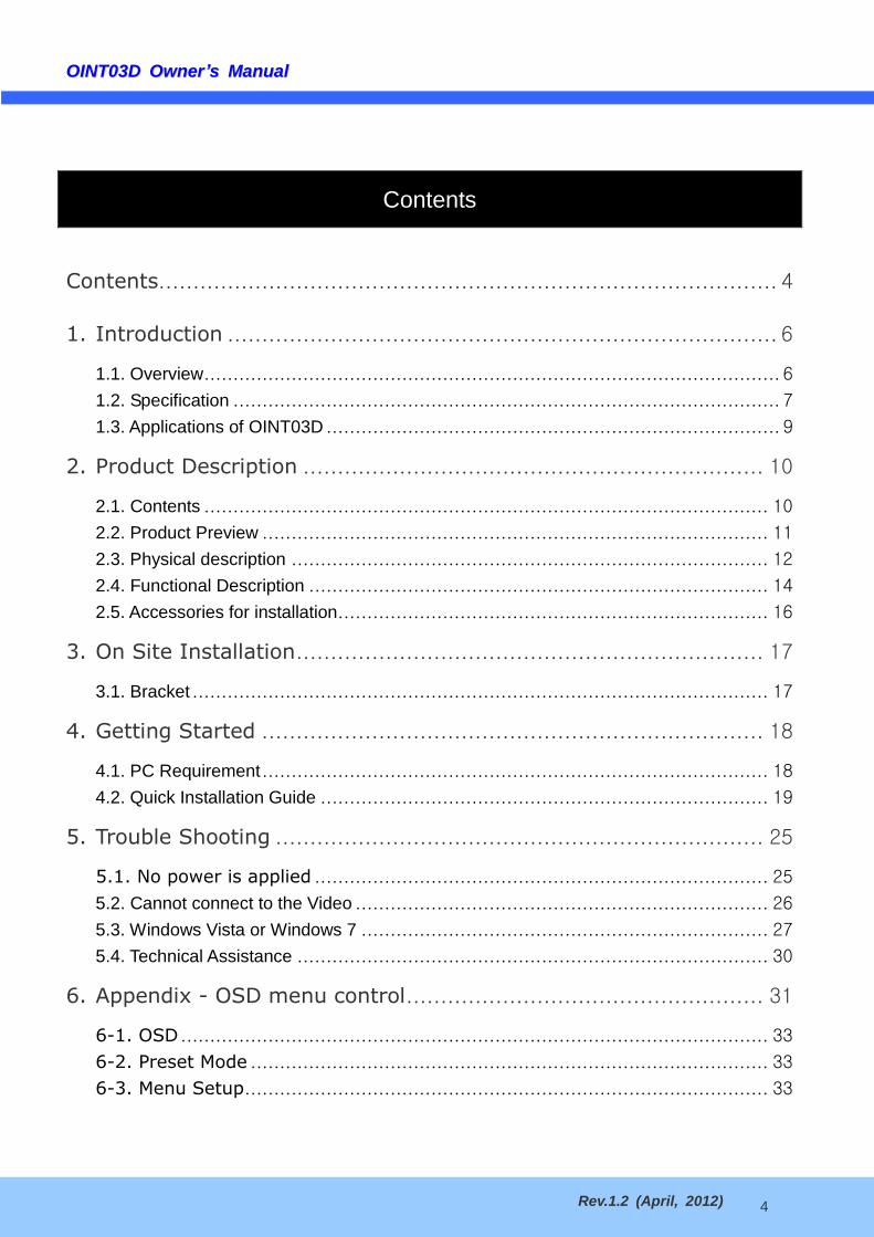
OOIINNTT0033DD OOwwnneerrrsquorsquoss MMaannuuaall
Rev12 (April 2012) 23
2) Connection through Speco-NVR
Click the camera assignment button for setting camera address Input the description address Ch
User ID Password and port and then click the save button After assignment procedure you must
click the SAVE button You can see the live video when you click the live view button as below When
you exit Speco-NVR you have to input the IDPW admin1234 Details for the Speco-NVR can be
found in [Speco-NVR Userrsquos Guide]
Figure 4-4 Speco-NVR
Camera Assignment
Camera Assignment
Live view
Save
Example
Exit Program
Default IDPW admin1234
OOIINNTT0033DD OOwwnneerrrsquorsquoss MMaannuuaall
Rev12 (April 2012) 24
4 Additional settings through connection to the Admin Page
All the parameters of new IP camera fallows factory default values For more sophisticated target application it
is needed to change parameters The admin page can be connected through
rdquohttpIP_addressHTTP_port_numberrdquoadminhtm
It is needed to enter ID and password of the administrator Default ID and password are admin 1234 It is
highly recommended to change the ID and password to prevent illegal access to the IP camera For more
detailed information please refer to the [Configuration_Guide] Guide
OOIINNTT0033DD OOwwnneerrrsquorsquoss MMaannuuaall
Rev12 (April 2012) 25
5 Trouble Shooting
51 No power is applied
In case of DC adaptor
If PoE is not applied the power and network connection should be made through separate cables
It is recommended to use DC adaptor supplied by provider for the feeding of the power In case of
replacing the DC power supply make sure that the power supply meets with the power
requirement of the IP camera to prevent damage or malfunction
OOIINNTT0033DD OOwwnneerrrsquorsquoss MMaannuuaall
Rev12 (April 2012) 26
52 Cannot connect to the Video
Check the status of the network connection through PING test
Try the following on your PC
- Start gt Run gt Cmd gt Ping IP address (Ex Ping 172164251)
- If ldquoReply from ~rdquo message is returned ( in the figure below) the network connection is in normal
state Try connection to the video again If the problem persists or refer to other trouble shooting notes
- If ldquoRequest timed outrdquo message is returned ( in the figure below) the network connection or
network setting is not in normal state Check the network cable and settings
1
2
1 2
OOIINNTT0033DD OOwwnneerrrsquorsquoss MMaannuuaall
Rev12 (April 2012) 27
53 Windows Vista or Windows 7
Windows Vista and Windows 7 users need to configure UAC (User Access Control) and Privilege Level for
proper recording and still video capture in Speco-NVR and Web Viewer
ltWindows Vistagt
1 UAC (User Access Control) configuration
1) Double-click ldquoUser Accountsrdquo in control panel
2) Double-click ldquoTurn User Account Control on or offrdquo
3) Uncheck ldquoUse UAC to help protect your computerrdquo
2 Privilege Level Control
1) Select ldquoNVRrdquo icon on the desktop
2) Click right mouse button and select ldquoPropertiesrdquo
3) Check ldquoPrivilege Levelrdquo in ldquoCompatibilityrdquo tab
OOIINNTT0033DD OOwwnneerrrsquorsquoss MMaannuuaall
Rev12 (April 2012) 28
ltWindows 7gt
1 UAC (User Access Control) configuration
1) Double-click ldquoUser Accountsrdquo in control panel
2) Double-click ldquoChange User Account Control settingrdquo
3) Set to ldquoNever notifyrdquo
OOIINNTT0033DD OOwwnneerrrsquorsquoss MMaannuuaall
Rev12 (April 2012) 29
2 Privilege Level Control
1) Select ldquoNVRrdquo icon on the desktop
2) Click right mouse button and select ldquopropertiesrdquo
3) Check ldquoPrivilege Levelrdquo in ldquoCompatibilityrdquo tab
OOIINNTT0033DD OOwwnneerrrsquorsquoss MMaannuuaall
Rev12 (April 2012) 30
54 Technical Assistance
If you need any technical assistance please contact your dealer For immediate service please provide the
following information
1 Model name
2 MAC address and Registration number
3 Purchase date
4 Description of the problem
5 Error message
OOIINNTT0033DD OOwwnneerrrsquorsquoss MMaannuuaall
Rev12 (April 2012) 31
6 Appendix - OSD menu control
To control OSD menu there are two methods
First is Video setup page in Administration Tool using Internet Browser as below
OOIINNTT0033DD OOwwnneerrrsquorsquoss MMaannuuaall
Rev12 (April 2012) 32
Scond is OSD menu controller on camera as below
OOIINNTT0033DD OOwwnneerrrsquorsquoss MMaannuuaall
Rev12 (April 2012) 33
6-1 OSD
All camera functions are menu driven for easy use
6-2 Preset Mode
1 Preset INDOOR OUTDOOR LOW LIGHT HALLWAY LOBBY ELEVATOR
- Used for a quick and easy setup for the installation environment
6-3 Menu Setup
1 Press the Function Setup switch
- Main setup menu is displayed on the monitor screen
2 Select a desired function using the Function Setup switch
- Place the cursor over a desired item
3 Set up a selected item by using the Function Setup switch
OOIINNTT0033DD OOwwnneerrrsquorsquoss MMaannuuaall
Rev12 (April 2012) 34
4 To finish the setting select RETURN and press the Function Setup switch
NOTE
An item with the icon also has sub menus To select a sub menu select an item with the icon and press
the Function Setup switch
An item with the - - - icon is unavailable due to function settings
OOIINNTT0033DD OOwwnneerrrsquorsquoss MMaannuuaall
Rev12 (April 2012) 35
6-4 Lens Setting
Using this function you can control the screen brightness
1 When the SETUP menu screen is displayed select LENS by using the Function Setup switch so that
the arrow indicates LENS
2 DC You can adjust the minimum shutter and maximum value of ESC shutter mode
NOTE
If color rolling occurs when using a DC lens set Shutter to Fixed (---)
OOIINNTT0033DD OOwwnneerrrsquorsquoss MMaannuuaall
Rev12 (April 2012) 36
6-5 Exposure Setting
1 When the SETUP menu screen is displayed select EXPOSURE by using the Function Setup Switch
2 Select a desired mode using the Function Setup switch
SHUTTER You can select either auto or manual shutter
--- Shutter speed is fixed at 160sec(150sec)
ESC Select this to control the shutter speed automatically If ESC is selected the shutter speed is
automatically controlled depending on the ambient illumination of the subject
MANUAL You can control shutter speed manually
(NTSC MODEL 160~1120000 PAL MODEL 150~1120000)
AFLK Select this when you see picture flicker this can happen when the frequency of the local
lighting clashes with the camera
NOTE
When the SHUTTER is set to MANUAL or AFLK mode INTENSIFY will be disabled
AGC(AUTO GAIN CONTROL) The higher the gain level the brighter the screen
- but the higher the noise
OFF Deactivates the AGC function
OOIINNTT0033DD OOwwnneerrrsquorsquoss MMaannuuaall
Rev12 (April 2012) 37
LOW Allows automatic gain control from 53dB to 32dB
HIGH Allows automatic gain control from 53dB to 37dB
INTENSIFY When it is night or dark the camera automatically detects then light level and
maintains a clear picture if this mode is activated
OFF Deactivates the INTENSIFY function
AUTO Activates the INTENSIFY function
RETURN Select this to save the changes in the EXPOSURE menu and return to the SETUP menu
NOTE
If you press the Function Setup switch to lsquoAUTOrsquo mode you can adjust brightness by increasing or
decreasing the shutter speed (x2 ~ x512)
Note that the higher the zoom level the brighter the screen but the more likely there will be a ghosting
effect
It is normal for Noise Spots and Whitish symptoms to appear in INTENSIFY mode when the D-ZOOM level
is increased
OOIINNTT0033DD OOwwnneerrrsquorsquoss MMaannuuaall
Rev12 (April 2012) 38
6-6 White Balance (White Bal) Setting
Use the White Balance function to adjust the screen color
1 When the SETUP menu screen is displayed select White Bal by using the function Setup switch so that
the arrow indicates White Bal
2 Select a desired mode using the Function Setup switch
Select one of the following 5 modes as appropriate for your purpose
ATW Select this when the color temperature is between 1700˚K and 11000˚K
OUTDOOR Select this when the color temperature is between 1700˚K and 11000˚K (sodium light
inclusion)
INDOOR Select this when the color temperature is between 4500˚K and 8500˚K
MANUAL Select this to fine-tune White Balance manually Set White Balance first by using the
ATW or AWC mode After that switch to MANUAL mode fine-tune the White Balance and then press
the Function Setup switch
AWCrarrSET To find the optimal luminance level for the current environment point the camera
towards a sheet of white paper and press the Function Setup switch If the environment changes
readjust it
NOTE
White Balance may not work properly under the following conditions In this case select the AWC mode
① When the color temperature of the environment surrounding the subject is out of the control range (eg
clear sky or sunset)
② When the ambient illumination of the subject is dim
③ If the camera is directed towards a fluorescent light or is installed in a place where illumination changes
dramatically the White Balance operation may become unstable
OOIINNTT0033DD OOwwnneerrrsquorsquoss MMaannuuaall
Rev12 (April 2012) 39
6-7 WDR Setting
WDR illuminates darker spots of an image while retaining the same light level for brighter spots to even out the
overall brightness of images with high contrast between bright and dark spots
1 When the SETUP menu screen is displayed select WDR by using the switch so that the arrow
indicates WDR
2 Use the switch to change the WDR level according to the contrast between bright and dark areas9
OOIINNTT0033DD OOwwnneerrrsquorsquoss MMaannuuaall
Rev12 (April 2012) 40
6-8 Backlight Setting
Unlike conventional cameras the 650Line Intensifier3trade Series are designed to deliver a distinctive subject and
background at the same time even when the subject is backlight by using the features of the proprietary W-V
DSP chip
1 When the SETUP menu screen is displayed select BACKLIGHT by using the Function Setup switch so
that the arrow indicates BACKLIGHT
2 Select a desired mode using the Function Setup switch
BLC Enables a user to directly select a desired area from a picture and to view the area more
clearly
HLC (High Light Compensation) If the scene contains extremely bright light areas such as from
car headlights the light can mask out much of the on-screen detail
- LEVEL Adjust level of the HLC function
- LIMIT Enable to change the operating condition
- MASK COLORTONE Change the color transparency of the masking area
(Black Red Blue Cyan Magenta)
- TOPBOTTOMLEFTRIGHT Adjust the area to be enhanced
OFF Not being used
3 Select a desired mode using the Function Setup switch and press the Function Setup switch
Select BLC to adjust the area to be enhanced then adjust the level
OOIINNTT0033DD OOwwnneerrrsquorsquoss MMaannuuaall
Rev12 (April 2012) 41
NOTE
Because there can be a difference in the effectiveness of HLC according to the amount of light area in the
screen optimize the installation angle for the best HLC performance
When dark the HLC is only activated when a bright light exceeding a specific size in NIGHT ONLY mode
The HLC is not activated in day light or when bright light is not present at night in NIGHT ONLY mode
BLC Function doesnt work in the BW mode of the DAYNIGHT menu
OOIINNTT0033DD OOwwnneerrrsquorsquoss MMaannuuaall
Rev12 (April 2012) 42
6-9 SPECO DNR Setting
This function reduces the background noise in a low luminance environment
1 When the SETUP menu screen is displayed select SPECO DNR by using the Function Setup switch
so that the arrow indicates SPECO DNR
2 Select a desired mode using the Function Setup switch
OFF Deactivates SPECO DNR Noise is not reduced
ON Activates SPECO DNR so that noise is reduced
3 Set the SPECO DNR mode to ON and press the Function Setup switch Then you can adjust the noise
reduction level
NOTE
You cannot set the SPECO DNR to lsquoONrsquo or lsquoOFFrsquo when the AGC mode of the EXPOSURE menu is
lsquoOFFrsquo
When adjusting the noise reduction level in the SPECO DNR mode remember that the higher the level set
the more the noise level will be reduced as will the brightness of the image
OOIINNTT0033DD OOwwnneerrrsquorsquoss MMaannuuaall
Rev12 (April 2012) 43
6-10 DayNight Setting
You can display pictures in color or black and white
1 When the SETUP menu screen is displayed select DAYNIGHTby using the Function Setup switch so
that the arrow indicates DAYNIGHT
2 Select a desired mode using the Function Setup Switch according to the picture display you want
COLOR The picture is always displayed in color
BW The picture is always displayed in black and white
- BURST MODE You can turn on or off the burst signal on BW mode
AUTO The mode is switched to Color in a normal environment but switches to BW mode when
ambient illumination is low To set up the switching time for AUTO mode press the Function Setup
switch You can turn on or off the burst signal on BW mode
OOIINNTT0033DD OOwwnneerrrsquorsquoss MMaannuuaall
Rev12 (April 2012) 44
- BURST MODE You can turn on or off the burst signal on BW mode
- DURATION You can select brightness of illumination about changing the daynight mode
- DWELLTIME You can select the duration time about changing the daynight mode
rarr3s 5s 7s 10s 15s 20s 30s 40 60s
The daynight switching point of the camera can be adjusted
NOTE
When AGC in the EXPOSURE menu is OFF --- mode operates as like selecting COLOR mode and
AUTO mode can not be selected
OOIINNTT0033DD OOwwnneerrrsquorsquoss MMaannuuaall
Rev12 (April 2012) 45
6-11 Special Setting
1 When the SETUP menu screen is displayed select SPECIAL by using the Function Setup switch so
that the arrow indicates SPECIAL
2 Select a desired mode using the Function Setup switch
OOIINNTT0033DD OOwwnneerrrsquorsquoss MMaannuuaall
Rev12 (April 2012) 46
IMAGE ADJ
1) When the SETUP menu screen is displayed select IMAGE ADJ by using the Function Setup switch
so that the arrow indicates IMAGE ADJ
2) Select a desired mode using the Function Setup switch
V-REV You can flip the picture vertically on the screen
H-REV You can flip the picture horizontally on the screen
D-ZOOM You can use a digital zoom of x1 ~ x16
DIS (Digital Image Stabilizer) This function mitigates any picture movement due to external factors
such as wind
FONT COLOR You can change the OSD font color (White Yellow Green Red Blue)
SHARPNESS As you increase this value the picture outline becomes stronger and clearer Adjust
this value appropriately depending on the sharpness of the picture
RETURN Select this to save the settings for the IMAGE ADJ menu and to return to the SETUP menu
NOTE
When the V-REV or H-REV mode is enabled the text on the screen does not flip
If you increase the SHARPNESS level too high the picture may become distorted or noise
may appear
MONITOR Please change the settings value of video appropriate to your monitor
1) LCD Please select this menu item when using a LCD monitor
2) CRT Please select this menu item when using a CRT monitor
3) USER Please use this menu item when using a monitor other than standard ones You can change
the gamma PED level and color gain in the sub menus
OOIINNTT0033DD OOwwnneerrrsquorsquoss MMaannuuaall
Rev12 (April 2012) 47
CAM TITLE If you enter a title the title will appear on the monitor
1) If the SPECIAL menu screen is displayed use the Function Setup switch so that the arrow indicates
CAM TITLE
2) Set it to ON by using the Function Setup switch
3) Press the Function Setup switch
4) Use the Function Setup switch to move to a desired letter and select the letter by pressing the
Function Setup switch Repeat this to enter multiple letters You can enter up to 15 letters
5) Enter a title move the cursor to POS and press the Function Setup switch The entered title
appears on the screen Select the position to display the title on the screen by using the Function Setup
switch and press the Function Setup switch When the position is determined select END and press
the Function Setup switch to return to the SPECIAL menu
OOIINNTT0033DD OOwwnneerrrsquorsquoss MMaannuuaall
Rev12 (April 2012) 48
NOTE
When the CAM TITLE menu is lsquoOFFrsquo no title will be displayed on the monitor screen even if you enter one
Only English is available in this mode
If you move the cursor to CLR and press the Function Setup switch all the letters are deleted To edit a
letter change the cursor to the bottom left arrow and press the Function Setup switch Move the cursor over the
letter to be edited move the cursor to the letter to be inserted and then press the Function Setup switch
SYNC In areas where the supply is at 60Hz(NTSC) 50Hz(PAL) you can synchronize the output
phase of multiple cameras using the power synchronization function (Line-Lock) without using a
synchronization signal generator
- INT Internal Synchronization Type
- LL Power Synchronization Type Line-lock
Press the Function Setup switch
You can select a desired phase from 0 to 359 when select phase
NOTE
When using AC power at 60Hz(NTSC) 50Hz(PAL) frequency you can use the LL type synchronization
When the power is DC 12V the SYNC menu is fixed to the lsquoINTrsquo mode
MOTION DET This product has a feature that allows you to observe movement of objects in 8
different areas on the screen and the words MOTION DETECTED appear on the screen when
movement is detected Activity can be monitor more efficiently
1) When the SPECIAL menu screen is displayed press the Function Setup switch so that the arrow
OOIINNTT0033DD OOwwnneerrrsquorsquoss MMaannuuaall
Rev12 (April 2012) 49
indicates lsquoMOTION DETrsquo
2) Set up the mode using the Function Setup switch
- SENSITIVITY You can select up to 8 MD areas When SENSITIVITY number is high motion
detection sensitivity is increased to recognize even small movement
- AREA MODE Determines whether to use the MD area selected in SENSITIVITY
- SEL POS Determines which of the 4 vertices of each MD area is to be used
- XPOS Determines the coordinate of the horizontal axis for SEL POS
- YPOS Determines the coordinate of the vertical axis for SEL POS
- FILLrarrSET Fills in a selected MD area The color of the area can be selected from brown orange
blue cyan green yellow magenta and red
- RETURN Select this to save the MOTION DET menu settings and return to the SPECIAL menu
PRIVACY Mask an area you want to hide on the screen
1) When the SPECIAL menu screen is displayed press the Function Setup switch so that the arrow
indicates PRIVACY
2) Set up the mode using the Function Setup switch
- AREA You can select up to 12 PRIVACY areas
- MODE Determines whether to use the area selected in the AREA
- MASK COLOR Determine area color You can select Green Red Blue Black White and Gray
- MASK TONE Adjust the brightness of MASK COLOR
- TOPBOTTOMLEFTRIGHT Adjust the size and position of the selected area
- RETURN Select this to save the PRIVACY menu settings and return to the SPECIAL menu
OOIINNTT0033DD OOwwnneerrrsquorsquoss MMaannuuaall
Rev12 (April 2012) 50
6-12 RETURN Setting
Select a desired RETURN mode using the Function Setup Switch
- SAVE Save the current settings and RETURN the MAIN SETUP menu
- NOT SAVE Do not save the current settings and RETURN the MAIN SETUP menu
- RESET Resets the camera settings to the factory defaults Language Communication and Monitor
Settings are not initialized
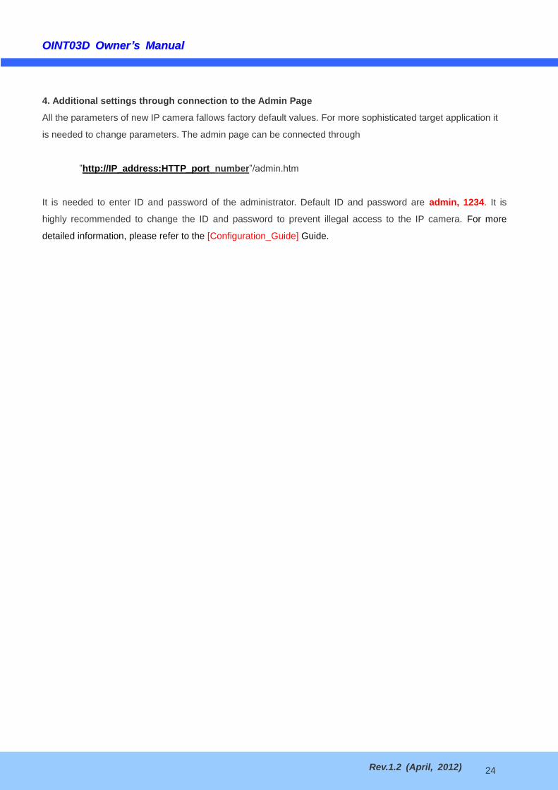
OOIINNTT0033DD OOwwnneerrrsquorsquoss MMaannuuaall
Rev12 (April 2012) 36
6-5 Exposure Setting
1 When the SETUP menu screen is displayed select EXPOSURE by using the Function Setup Switch
2 Select a desired mode using the Function Setup switch
SHUTTER You can select either auto or manual shutter
--- Shutter speed is fixed at 160sec(150sec)
ESC Select this to control the shutter speed automatically If ESC is selected the shutter speed is
automatically controlled depending on the ambient illumination of the subject
MANUAL You can control shutter speed manually
(NTSC MODEL 160~1120000 PAL MODEL 150~1120000)
AFLK Select this when you see picture flicker this can happen when the frequency of the local
lighting clashes with the camera
NOTE
When the SHUTTER is set to MANUAL or AFLK mode INTENSIFY will be disabled
AGC(AUTO GAIN CONTROL) The higher the gain level the brighter the screen
- but the higher the noise
OFF Deactivates the AGC function
OOIINNTT0033DD OOwwnneerrrsquorsquoss MMaannuuaall
Rev12 (April 2012) 37
LOW Allows automatic gain control from 53dB to 32dB
HIGH Allows automatic gain control from 53dB to 37dB
INTENSIFY When it is night or dark the camera automatically detects then light level and
maintains a clear picture if this mode is activated
OFF Deactivates the INTENSIFY function
AUTO Activates the INTENSIFY function
RETURN Select this to save the changes in the EXPOSURE menu and return to the SETUP menu
NOTE
If you press the Function Setup switch to lsquoAUTOrsquo mode you can adjust brightness by increasing or
decreasing the shutter speed (x2 ~ x512)
Note that the higher the zoom level the brighter the screen but the more likely there will be a ghosting
effect
It is normal for Noise Spots and Whitish symptoms to appear in INTENSIFY mode when the D-ZOOM level
is increased
OOIINNTT0033DD OOwwnneerrrsquorsquoss MMaannuuaall
Rev12 (April 2012) 38
6-6 White Balance (White Bal) Setting
Use the White Balance function to adjust the screen color
1 When the SETUP menu screen is displayed select White Bal by using the function Setup switch so that
the arrow indicates White Bal
2 Select a desired mode using the Function Setup switch
Select one of the following 5 modes as appropriate for your purpose
ATW Select this when the color temperature is between 1700˚K and 11000˚K
OUTDOOR Select this when the color temperature is between 1700˚K and 11000˚K (sodium light
inclusion)
INDOOR Select this when the color temperature is between 4500˚K and 8500˚K
MANUAL Select this to fine-tune White Balance manually Set White Balance first by using the
ATW or AWC mode After that switch to MANUAL mode fine-tune the White Balance and then press
the Function Setup switch
AWCrarrSET To find the optimal luminance level for the current environment point the camera
towards a sheet of white paper and press the Function Setup switch If the environment changes
readjust it
NOTE
White Balance may not work properly under the following conditions In this case select the AWC mode
① When the color temperature of the environment surrounding the subject is out of the control range (eg
clear sky or sunset)
② When the ambient illumination of the subject is dim
③ If the camera is directed towards a fluorescent light or is installed in a place where illumination changes
dramatically the White Balance operation may become unstable
OOIINNTT0033DD OOwwnneerrrsquorsquoss MMaannuuaall
Rev12 (April 2012) 39
6-7 WDR Setting
WDR illuminates darker spots of an image while retaining the same light level for brighter spots to even out the
overall brightness of images with high contrast between bright and dark spots
1 When the SETUP menu screen is displayed select WDR by using the switch so that the arrow
indicates WDR
2 Use the switch to change the WDR level according to the contrast between bright and dark areas9
OOIINNTT0033DD OOwwnneerrrsquorsquoss MMaannuuaall
Rev12 (April 2012) 40
6-8 Backlight Setting
Unlike conventional cameras the 650Line Intensifier3trade Series are designed to deliver a distinctive subject and
background at the same time even when the subject is backlight by using the features of the proprietary W-V
DSP chip
1 When the SETUP menu screen is displayed select BACKLIGHT by using the Function Setup switch so
that the arrow indicates BACKLIGHT
2 Select a desired mode using the Function Setup switch
BLC Enables a user to directly select a desired area from a picture and to view the area more
clearly
HLC (High Light Compensation) If the scene contains extremely bright light areas such as from
car headlights the light can mask out much of the on-screen detail
- LEVEL Adjust level of the HLC function
- LIMIT Enable to change the operating condition
- MASK COLORTONE Change the color transparency of the masking area
(Black Red Blue Cyan Magenta)
- TOPBOTTOMLEFTRIGHT Adjust the area to be enhanced
OFF Not being used
3 Select a desired mode using the Function Setup switch and press the Function Setup switch
Select BLC to adjust the area to be enhanced then adjust the level
OOIINNTT0033DD OOwwnneerrrsquorsquoss MMaannuuaall
Rev12 (April 2012) 41
NOTE
Because there can be a difference in the effectiveness of HLC according to the amount of light area in the
screen optimize the installation angle for the best HLC performance
When dark the HLC is only activated when a bright light exceeding a specific size in NIGHT ONLY mode
The HLC is not activated in day light or when bright light is not present at night in NIGHT ONLY mode
BLC Function doesnt work in the BW mode of the DAYNIGHT menu
OOIINNTT0033DD OOwwnneerrrsquorsquoss MMaannuuaall
Rev12 (April 2012) 42
6-9 SPECO DNR Setting
This function reduces the background noise in a low luminance environment
1 When the SETUP menu screen is displayed select SPECO DNR by using the Function Setup switch
so that the arrow indicates SPECO DNR
2 Select a desired mode using the Function Setup switch
OFF Deactivates SPECO DNR Noise is not reduced
ON Activates SPECO DNR so that noise is reduced
3 Set the SPECO DNR mode to ON and press the Function Setup switch Then you can adjust the noise
reduction level
NOTE
You cannot set the SPECO DNR to lsquoONrsquo or lsquoOFFrsquo when the AGC mode of the EXPOSURE menu is
lsquoOFFrsquo
When adjusting the noise reduction level in the SPECO DNR mode remember that the higher the level set
the more the noise level will be reduced as will the brightness of the image
OOIINNTT0033DD OOwwnneerrrsquorsquoss MMaannuuaall
Rev12 (April 2012) 43
6-10 DayNight Setting
You can display pictures in color or black and white
1 When the SETUP menu screen is displayed select DAYNIGHTby using the Function Setup switch so
that the arrow indicates DAYNIGHT
2 Select a desired mode using the Function Setup Switch according to the picture display you want
COLOR The picture is always displayed in color
BW The picture is always displayed in black and white
- BURST MODE You can turn on or off the burst signal on BW mode
AUTO The mode is switched to Color in a normal environment but switches to BW mode when
ambient illumination is low To set up the switching time for AUTO mode press the Function Setup
switch You can turn on or off the burst signal on BW mode
OOIINNTT0033DD OOwwnneerrrsquorsquoss MMaannuuaall
Rev12 (April 2012) 44
- BURST MODE You can turn on or off the burst signal on BW mode
- DURATION You can select brightness of illumination about changing the daynight mode
- DWELLTIME You can select the duration time about changing the daynight mode
rarr3s 5s 7s 10s 15s 20s 30s 40 60s
The daynight switching point of the camera can be adjusted
NOTE
When AGC in the EXPOSURE menu is OFF --- mode operates as like selecting COLOR mode and
AUTO mode can not be selected
OOIINNTT0033DD OOwwnneerrrsquorsquoss MMaannuuaall
Rev12 (April 2012) 45
6-11 Special Setting
1 When the SETUP menu screen is displayed select SPECIAL by using the Function Setup switch so
that the arrow indicates SPECIAL
2 Select a desired mode using the Function Setup switch
OOIINNTT0033DD OOwwnneerrrsquorsquoss MMaannuuaall
Rev12 (April 2012) 46
IMAGE ADJ
1) When the SETUP menu screen is displayed select IMAGE ADJ by using the Function Setup switch
so that the arrow indicates IMAGE ADJ
2) Select a desired mode using the Function Setup switch
V-REV You can flip the picture vertically on the screen
H-REV You can flip the picture horizontally on the screen
D-ZOOM You can use a digital zoom of x1 ~ x16
DIS (Digital Image Stabilizer) This function mitigates any picture movement due to external factors
such as wind
FONT COLOR You can change the OSD font color (White Yellow Green Red Blue)
SHARPNESS As you increase this value the picture outline becomes stronger and clearer Adjust
this value appropriately depending on the sharpness of the picture
RETURN Select this to save the settings for the IMAGE ADJ menu and to return to the SETUP menu
NOTE
When the V-REV or H-REV mode is enabled the text on the screen does not flip
If you increase the SHARPNESS level too high the picture may become distorted or noise
may appear
MONITOR Please change the settings value of video appropriate to your monitor
1) LCD Please select this menu item when using a LCD monitor
2) CRT Please select this menu item when using a CRT monitor
3) USER Please use this menu item when using a monitor other than standard ones You can change
the gamma PED level and color gain in the sub menus
OOIINNTT0033DD OOwwnneerrrsquorsquoss MMaannuuaall
Rev12 (April 2012) 47
CAM TITLE If you enter a title the title will appear on the monitor
1) If the SPECIAL menu screen is displayed use the Function Setup switch so that the arrow indicates
CAM TITLE
2) Set it to ON by using the Function Setup switch
3) Press the Function Setup switch
4) Use the Function Setup switch to move to a desired letter and select the letter by pressing the
Function Setup switch Repeat this to enter multiple letters You can enter up to 15 letters
5) Enter a title move the cursor to POS and press the Function Setup switch The entered title
appears on the screen Select the position to display the title on the screen by using the Function Setup
switch and press the Function Setup switch When the position is determined select END and press
the Function Setup switch to return to the SPECIAL menu
OOIINNTT0033DD OOwwnneerrrsquorsquoss MMaannuuaall
Rev12 (April 2012) 48
NOTE
When the CAM TITLE menu is lsquoOFFrsquo no title will be displayed on the monitor screen even if you enter one
Only English is available in this mode
If you move the cursor to CLR and press the Function Setup switch all the letters are deleted To edit a
letter change the cursor to the bottom left arrow and press the Function Setup switch Move the cursor over the
letter to be edited move the cursor to the letter to be inserted and then press the Function Setup switch
SYNC In areas where the supply is at 60Hz(NTSC) 50Hz(PAL) you can synchronize the output
phase of multiple cameras using the power synchronization function (Line-Lock) without using a
synchronization signal generator
- INT Internal Synchronization Type
- LL Power Synchronization Type Line-lock
Press the Function Setup switch
You can select a desired phase from 0 to 359 when select phase
NOTE
When using AC power at 60Hz(NTSC) 50Hz(PAL) frequency you can use the LL type synchronization
When the power is DC 12V the SYNC menu is fixed to the lsquoINTrsquo mode
MOTION DET This product has a feature that allows you to observe movement of objects in 8
different areas on the screen and the words MOTION DETECTED appear on the screen when
movement is detected Activity can be monitor more efficiently
1) When the SPECIAL menu screen is displayed press the Function Setup switch so that the arrow
OOIINNTT0033DD OOwwnneerrrsquorsquoss MMaannuuaall
Rev12 (April 2012) 49
indicates lsquoMOTION DETrsquo
2) Set up the mode using the Function Setup switch
- SENSITIVITY You can select up to 8 MD areas When SENSITIVITY number is high motion
detection sensitivity is increased to recognize even small movement
- AREA MODE Determines whether to use the MD area selected in SENSITIVITY
- SEL POS Determines which of the 4 vertices of each MD area is to be used
- XPOS Determines the coordinate of the horizontal axis for SEL POS
- YPOS Determines the coordinate of the vertical axis for SEL POS
- FILLrarrSET Fills in a selected MD area The color of the area can be selected from brown orange
blue cyan green yellow magenta and red
- RETURN Select this to save the MOTION DET menu settings and return to the SPECIAL menu
PRIVACY Mask an area you want to hide on the screen
1) When the SPECIAL menu screen is displayed press the Function Setup switch so that the arrow
indicates PRIVACY
2) Set up the mode using the Function Setup switch
- AREA You can select up to 12 PRIVACY areas
- MODE Determines whether to use the area selected in the AREA
- MASK COLOR Determine area color You can select Green Red Blue Black White and Gray
- MASK TONE Adjust the brightness of MASK COLOR
- TOPBOTTOMLEFTRIGHT Adjust the size and position of the selected area
- RETURN Select this to save the PRIVACY menu settings and return to the SPECIAL menu
OOIINNTT0033DD OOwwnneerrrsquorsquoss MMaannuuaall
Rev12 (April 2012) 50
6-12 RETURN Setting
Select a desired RETURN mode using the Function Setup Switch
- SAVE Save the current settings and RETURN the MAIN SETUP menu
- NOT SAVE Do not save the current settings and RETURN the MAIN SETUP menu
- RESET Resets the camera settings to the factory defaults Language Communication and Monitor
Settings are not initialized
OOIINNTT0033DD OOwwnneerrrsquorsquoss MMaannuuaall
Rev12 (April 2012) 37
LOW Allows automatic gain control from 53dB to 32dB
HIGH Allows automatic gain control from 53dB to 37dB
INTENSIFY When it is night or dark the camera automatically detects then light level and
maintains a clear picture if this mode is activated
OFF Deactivates the INTENSIFY function
AUTO Activates the INTENSIFY function
RETURN Select this to save the changes in the EXPOSURE menu and return to the SETUP menu
NOTE
If you press the Function Setup switch to lsquoAUTOrsquo mode you can adjust brightness by increasing or
decreasing the shutter speed (x2 ~ x512)
Note that the higher the zoom level the brighter the screen but the more likely there will be a ghosting
effect
It is normal for Noise Spots and Whitish symptoms to appear in INTENSIFY mode when the D-ZOOM level
is increased
OOIINNTT0033DD OOwwnneerrrsquorsquoss MMaannuuaall
Rev12 (April 2012) 38
6-6 White Balance (White Bal) Setting
Use the White Balance function to adjust the screen color
1 When the SETUP menu screen is displayed select White Bal by using the function Setup switch so that
the arrow indicates White Bal
2 Select a desired mode using the Function Setup switch
Select one of the following 5 modes as appropriate for your purpose
ATW Select this when the color temperature is between 1700˚K and 11000˚K
OUTDOOR Select this when the color temperature is between 1700˚K and 11000˚K (sodium light
inclusion)
INDOOR Select this when the color temperature is between 4500˚K and 8500˚K
MANUAL Select this to fine-tune White Balance manually Set White Balance first by using the
ATW or AWC mode After that switch to MANUAL mode fine-tune the White Balance and then press
the Function Setup switch
AWCrarrSET To find the optimal luminance level for the current environment point the camera
towards a sheet of white paper and press the Function Setup switch If the environment changes
readjust it
NOTE
White Balance may not work properly under the following conditions In this case select the AWC mode
① When the color temperature of the environment surrounding the subject is out of the control range (eg
clear sky or sunset)
② When the ambient illumination of the subject is dim
③ If the camera is directed towards a fluorescent light or is installed in a place where illumination changes
dramatically the White Balance operation may become unstable
OOIINNTT0033DD OOwwnneerrrsquorsquoss MMaannuuaall
Rev12 (April 2012) 39
6-7 WDR Setting
WDR illuminates darker spots of an image while retaining the same light level for brighter spots to even out the
overall brightness of images with high contrast between bright and dark spots
1 When the SETUP menu screen is displayed select WDR by using the switch so that the arrow
indicates WDR
2 Use the switch to change the WDR level according to the contrast between bright and dark areas9
OOIINNTT0033DD OOwwnneerrrsquorsquoss MMaannuuaall
Rev12 (April 2012) 40
6-8 Backlight Setting
Unlike conventional cameras the 650Line Intensifier3trade Series are designed to deliver a distinctive subject and
background at the same time even when the subject is backlight by using the features of the proprietary W-V
DSP chip
1 When the SETUP menu screen is displayed select BACKLIGHT by using the Function Setup switch so
that the arrow indicates BACKLIGHT
2 Select a desired mode using the Function Setup switch
BLC Enables a user to directly select a desired area from a picture and to view the area more
clearly
HLC (High Light Compensation) If the scene contains extremely bright light areas such as from
car headlights the light can mask out much of the on-screen detail
- LEVEL Adjust level of the HLC function
- LIMIT Enable to change the operating condition
- MASK COLORTONE Change the color transparency of the masking area
(Black Red Blue Cyan Magenta)
- TOPBOTTOMLEFTRIGHT Adjust the area to be enhanced
OFF Not being used
3 Select a desired mode using the Function Setup switch and press the Function Setup switch
Select BLC to adjust the area to be enhanced then adjust the level
OOIINNTT0033DD OOwwnneerrrsquorsquoss MMaannuuaall
Rev12 (April 2012) 41
NOTE
Because there can be a difference in the effectiveness of HLC according to the amount of light area in the
screen optimize the installation angle for the best HLC performance
When dark the HLC is only activated when a bright light exceeding a specific size in NIGHT ONLY mode
The HLC is not activated in day light or when bright light is not present at night in NIGHT ONLY mode
BLC Function doesnt work in the BW mode of the DAYNIGHT menu
OOIINNTT0033DD OOwwnneerrrsquorsquoss MMaannuuaall
Rev12 (April 2012) 42
6-9 SPECO DNR Setting
This function reduces the background noise in a low luminance environment
1 When the SETUP menu screen is displayed select SPECO DNR by using the Function Setup switch
so that the arrow indicates SPECO DNR
2 Select a desired mode using the Function Setup switch
OFF Deactivates SPECO DNR Noise is not reduced
ON Activates SPECO DNR so that noise is reduced
3 Set the SPECO DNR mode to ON and press the Function Setup switch Then you can adjust the noise
reduction level
NOTE
You cannot set the SPECO DNR to lsquoONrsquo or lsquoOFFrsquo when the AGC mode of the EXPOSURE menu is
lsquoOFFrsquo
When adjusting the noise reduction level in the SPECO DNR mode remember that the higher the level set
the more the noise level will be reduced as will the brightness of the image
OOIINNTT0033DD OOwwnneerrrsquorsquoss MMaannuuaall
Rev12 (April 2012) 43
6-10 DayNight Setting
You can display pictures in color or black and white
1 When the SETUP menu screen is displayed select DAYNIGHTby using the Function Setup switch so
that the arrow indicates DAYNIGHT
2 Select a desired mode using the Function Setup Switch according to the picture display you want
COLOR The picture is always displayed in color
BW The picture is always displayed in black and white
- BURST MODE You can turn on or off the burst signal on BW mode
AUTO The mode is switched to Color in a normal environment but switches to BW mode when
ambient illumination is low To set up the switching time for AUTO mode press the Function Setup
switch You can turn on or off the burst signal on BW mode
OOIINNTT0033DD OOwwnneerrrsquorsquoss MMaannuuaall
Rev12 (April 2012) 44
- BURST MODE You can turn on or off the burst signal on BW mode
- DURATION You can select brightness of illumination about changing the daynight mode
- DWELLTIME You can select the duration time about changing the daynight mode
rarr3s 5s 7s 10s 15s 20s 30s 40 60s
The daynight switching point of the camera can be adjusted
NOTE
When AGC in the EXPOSURE menu is OFF --- mode operates as like selecting COLOR mode and
AUTO mode can not be selected
OOIINNTT0033DD OOwwnneerrrsquorsquoss MMaannuuaall
Rev12 (April 2012) 45
6-11 Special Setting
1 When the SETUP menu screen is displayed select SPECIAL by using the Function Setup switch so
that the arrow indicates SPECIAL
2 Select a desired mode using the Function Setup switch
OOIINNTT0033DD OOwwnneerrrsquorsquoss MMaannuuaall
Rev12 (April 2012) 46
IMAGE ADJ
1) When the SETUP menu screen is displayed select IMAGE ADJ by using the Function Setup switch
so that the arrow indicates IMAGE ADJ
2) Select a desired mode using the Function Setup switch
V-REV You can flip the picture vertically on the screen
H-REV You can flip the picture horizontally on the screen
D-ZOOM You can use a digital zoom of x1 ~ x16
DIS (Digital Image Stabilizer) This function mitigates any picture movement due to external factors
such as wind
FONT COLOR You can change the OSD font color (White Yellow Green Red Blue)
SHARPNESS As you increase this value the picture outline becomes stronger and clearer Adjust
this value appropriately depending on the sharpness of the picture
RETURN Select this to save the settings for the IMAGE ADJ menu and to return to the SETUP menu
NOTE
When the V-REV or H-REV mode is enabled the text on the screen does not flip
If you increase the SHARPNESS level too high the picture may become distorted or noise
may appear
MONITOR Please change the settings value of video appropriate to your monitor
1) LCD Please select this menu item when using a LCD monitor
2) CRT Please select this menu item when using a CRT monitor
3) USER Please use this menu item when using a monitor other than standard ones You can change
the gamma PED level and color gain in the sub menus
OOIINNTT0033DD OOwwnneerrrsquorsquoss MMaannuuaall
Rev12 (April 2012) 47
CAM TITLE If you enter a title the title will appear on the monitor
1) If the SPECIAL menu screen is displayed use the Function Setup switch so that the arrow indicates
CAM TITLE
2) Set it to ON by using the Function Setup switch
3) Press the Function Setup switch
4) Use the Function Setup switch to move to a desired letter and select the letter by pressing the
Function Setup switch Repeat this to enter multiple letters You can enter up to 15 letters
5) Enter a title move the cursor to POS and press the Function Setup switch The entered title
appears on the screen Select the position to display the title on the screen by using the Function Setup
switch and press the Function Setup switch When the position is determined select END and press
the Function Setup switch to return to the SPECIAL menu
OOIINNTT0033DD OOwwnneerrrsquorsquoss MMaannuuaall
Rev12 (April 2012) 48
NOTE
When the CAM TITLE menu is lsquoOFFrsquo no title will be displayed on the monitor screen even if you enter one
Only English is available in this mode
If you move the cursor to CLR and press the Function Setup switch all the letters are deleted To edit a
letter change the cursor to the bottom left arrow and press the Function Setup switch Move the cursor over the
letter to be edited move the cursor to the letter to be inserted and then press the Function Setup switch
SYNC In areas where the supply is at 60Hz(NTSC) 50Hz(PAL) you can synchronize the output
phase of multiple cameras using the power synchronization function (Line-Lock) without using a
synchronization signal generator
- INT Internal Synchronization Type
- LL Power Synchronization Type Line-lock
Press the Function Setup switch
You can select a desired phase from 0 to 359 when select phase
NOTE
When using AC power at 60Hz(NTSC) 50Hz(PAL) frequency you can use the LL type synchronization
When the power is DC 12V the SYNC menu is fixed to the lsquoINTrsquo mode
MOTION DET This product has a feature that allows you to observe movement of objects in 8
different areas on the screen and the words MOTION DETECTED appear on the screen when
movement is detected Activity can be monitor more efficiently
1) When the SPECIAL menu screen is displayed press the Function Setup switch so that the arrow
OOIINNTT0033DD OOwwnneerrrsquorsquoss MMaannuuaall
Rev12 (April 2012) 49
indicates lsquoMOTION DETrsquo
2) Set up the mode using the Function Setup switch
- SENSITIVITY You can select up to 8 MD areas When SENSITIVITY number is high motion
detection sensitivity is increased to recognize even small movement
- AREA MODE Determines whether to use the MD area selected in SENSITIVITY
- SEL POS Determines which of the 4 vertices of each MD area is to be used
- XPOS Determines the coordinate of the horizontal axis for SEL POS
- YPOS Determines the coordinate of the vertical axis for SEL POS
- FILLrarrSET Fills in a selected MD area The color of the area can be selected from brown orange
blue cyan green yellow magenta and red
- RETURN Select this to save the MOTION DET menu settings and return to the SPECIAL menu
PRIVACY Mask an area you want to hide on the screen
1) When the SPECIAL menu screen is displayed press the Function Setup switch so that the arrow
indicates PRIVACY
2) Set up the mode using the Function Setup switch
- AREA You can select up to 12 PRIVACY areas
- MODE Determines whether to use the area selected in the AREA
- MASK COLOR Determine area color You can select Green Red Blue Black White and Gray
- MASK TONE Adjust the brightness of MASK COLOR
- TOPBOTTOMLEFTRIGHT Adjust the size and position of the selected area
- RETURN Select this to save the PRIVACY menu settings and return to the SPECIAL menu
OOIINNTT0033DD OOwwnneerrrsquorsquoss MMaannuuaall
Rev12 (April 2012) 50
6-12 RETURN Setting
Select a desired RETURN mode using the Function Setup Switch
- SAVE Save the current settings and RETURN the MAIN SETUP menu
- NOT SAVE Do not save the current settings and RETURN the MAIN SETUP menu
- RESET Resets the camera settings to the factory defaults Language Communication and Monitor
Settings are not initialized

OOIINNTT0033DD OOwwnneerrrsquorsquoss MMaannuuaall
Rev12 (April 2012) 45
6-11 Special Setting
1 When the SETUP menu screen is displayed select SPECIAL by using the Function Setup switch so
that the arrow indicates SPECIAL
2 Select a desired mode using the Function Setup switch
OOIINNTT0033DD OOwwnneerrrsquorsquoss MMaannuuaall
Rev12 (April 2012) 46
IMAGE ADJ
1) When the SETUP menu screen is displayed select IMAGE ADJ by using the Function Setup switch
so that the arrow indicates IMAGE ADJ
2) Select a desired mode using the Function Setup switch
V-REV You can flip the picture vertically on the screen
H-REV You can flip the picture horizontally on the screen
D-ZOOM You can use a digital zoom of x1 ~ x16
DIS (Digital Image Stabilizer) This function mitigates any picture movement due to external factors
such as wind
FONT COLOR You can change the OSD font color (White Yellow Green Red Blue)
SHARPNESS As you increase this value the picture outline becomes stronger and clearer Adjust
this value appropriately depending on the sharpness of the picture
RETURN Select this to save the settings for the IMAGE ADJ menu and to return to the SETUP menu
NOTE
When the V-REV or H-REV mode is enabled the text on the screen does not flip
If you increase the SHARPNESS level too high the picture may become distorted or noise
may appear
MONITOR Please change the settings value of video appropriate to your monitor
1) LCD Please select this menu item when using a LCD monitor
2) CRT Please select this menu item when using a CRT monitor
3) USER Please use this menu item when using a monitor other than standard ones You can change
the gamma PED level and color gain in the sub menus
OOIINNTT0033DD OOwwnneerrrsquorsquoss MMaannuuaall
Rev12 (April 2012) 47
CAM TITLE If you enter a title the title will appear on the monitor
1) If the SPECIAL menu screen is displayed use the Function Setup switch so that the arrow indicates
CAM TITLE
2) Set it to ON by using the Function Setup switch
3) Press the Function Setup switch
4) Use the Function Setup switch to move to a desired letter and select the letter by pressing the
Function Setup switch Repeat this to enter multiple letters You can enter up to 15 letters
5) Enter a title move the cursor to POS and press the Function Setup switch The entered title
appears on the screen Select the position to display the title on the screen by using the Function Setup
switch and press the Function Setup switch When the position is determined select END and press
the Function Setup switch to return to the SPECIAL menu
OOIINNTT0033DD OOwwnneerrrsquorsquoss MMaannuuaall
Rev12 (April 2012) 48
NOTE
When the CAM TITLE menu is lsquoOFFrsquo no title will be displayed on the monitor screen even if you enter one
Only English is available in this mode
If you move the cursor to CLR and press the Function Setup switch all the letters are deleted To edit a
letter change the cursor to the bottom left arrow and press the Function Setup switch Move the cursor over the
letter to be edited move the cursor to the letter to be inserted and then press the Function Setup switch
SYNC In areas where the supply is at 60Hz(NTSC) 50Hz(PAL) you can synchronize the output
phase of multiple cameras using the power synchronization function (Line-Lock) without using a
synchronization signal generator
- INT Internal Synchronization Type
- LL Power Synchronization Type Line-lock
Press the Function Setup switch
You can select a desired phase from 0 to 359 when select phase
NOTE
When using AC power at 60Hz(NTSC) 50Hz(PAL) frequency you can use the LL type synchronization
When the power is DC 12V the SYNC menu is fixed to the lsquoINTrsquo mode
MOTION DET This product has a feature that allows you to observe movement of objects in 8
different areas on the screen and the words MOTION DETECTED appear on the screen when
movement is detected Activity can be monitor more efficiently
1) When the SPECIAL menu screen is displayed press the Function Setup switch so that the arrow
OOIINNTT0033DD OOwwnneerrrsquorsquoss MMaannuuaall
Rev12 (April 2012) 49
indicates lsquoMOTION DETrsquo
2) Set up the mode using the Function Setup switch
- SENSITIVITY You can select up to 8 MD areas When SENSITIVITY number is high motion
detection sensitivity is increased to recognize even small movement
- AREA MODE Determines whether to use the MD area selected in SENSITIVITY
- SEL POS Determines which of the 4 vertices of each MD area is to be used
- XPOS Determines the coordinate of the horizontal axis for SEL POS
- YPOS Determines the coordinate of the vertical axis for SEL POS
- FILLrarrSET Fills in a selected MD area The color of the area can be selected from brown orange
blue cyan green yellow magenta and red
- RETURN Select this to save the MOTION DET menu settings and return to the SPECIAL menu
PRIVACY Mask an area you want to hide on the screen
1) When the SPECIAL menu screen is displayed press the Function Setup switch so that the arrow
indicates PRIVACY
2) Set up the mode using the Function Setup switch
- AREA You can select up to 12 PRIVACY areas
- MODE Determines whether to use the area selected in the AREA
- MASK COLOR Determine area color You can select Green Red Blue Black White and Gray
- MASK TONE Adjust the brightness of MASK COLOR
- TOPBOTTOMLEFTRIGHT Adjust the size and position of the selected area
- RETURN Select this to save the PRIVACY menu settings and return to the SPECIAL menu
OOIINNTT0033DD OOwwnneerrrsquorsquoss MMaannuuaall
Rev12 (April 2012) 50
6-12 RETURN Setting
Select a desired RETURN mode using the Function Setup Switch
- SAVE Save the current settings and RETURN the MAIN SETUP menu
- NOT SAVE Do not save the current settings and RETURN the MAIN SETUP menu
- RESET Resets the camera settings to the factory defaults Language Communication and Monitor
Settings are not initialized
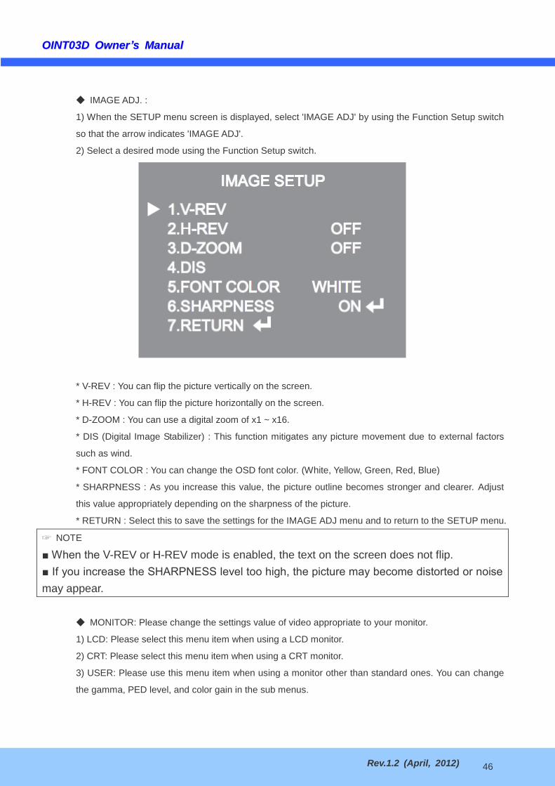
OOIINNTT0033DD OOwwnneerrrsquorsquoss MMaannuuaall
Rev12 (April 2012) 47
CAM TITLE If you enter a title the title will appear on the monitor
1) If the SPECIAL menu screen is displayed use the Function Setup switch so that the arrow indicates
CAM TITLE
2) Set it to ON by using the Function Setup switch
3) Press the Function Setup switch
4) Use the Function Setup switch to move to a desired letter and select the letter by pressing the
Function Setup switch Repeat this to enter multiple letters You can enter up to 15 letters
5) Enter a title move the cursor to POS and press the Function Setup switch The entered title
appears on the screen Select the position to display the title on the screen by using the Function Setup
switch and press the Function Setup switch When the position is determined select END and press
the Function Setup switch to return to the SPECIAL menu
OOIINNTT0033DD OOwwnneerrrsquorsquoss MMaannuuaall
Rev12 (April 2012) 48
NOTE
When the CAM TITLE menu is lsquoOFFrsquo no title will be displayed on the monitor screen even if you enter one
Only English is available in this mode
If you move the cursor to CLR and press the Function Setup switch all the letters are deleted To edit a
letter change the cursor to the bottom left arrow and press the Function Setup switch Move the cursor over the
letter to be edited move the cursor to the letter to be inserted and then press the Function Setup switch
SYNC In areas where the supply is at 60Hz(NTSC) 50Hz(PAL) you can synchronize the output
phase of multiple cameras using the power synchronization function (Line-Lock) without using a
synchronization signal generator
- INT Internal Synchronization Type
- LL Power Synchronization Type Line-lock
Press the Function Setup switch
You can select a desired phase from 0 to 359 when select phase
NOTE
When using AC power at 60Hz(NTSC) 50Hz(PAL) frequency you can use the LL type synchronization
When the power is DC 12V the SYNC menu is fixed to the lsquoINTrsquo mode
MOTION DET This product has a feature that allows you to observe movement of objects in 8
different areas on the screen and the words MOTION DETECTED appear on the screen when
movement is detected Activity can be monitor more efficiently
1) When the SPECIAL menu screen is displayed press the Function Setup switch so that the arrow
OOIINNTT0033DD OOwwnneerrrsquorsquoss MMaannuuaall
Rev12 (April 2012) 49
indicates lsquoMOTION DETrsquo
2) Set up the mode using the Function Setup switch
- SENSITIVITY You can select up to 8 MD areas When SENSITIVITY number is high motion
detection sensitivity is increased to recognize even small movement
- AREA MODE Determines whether to use the MD area selected in SENSITIVITY
- SEL POS Determines which of the 4 vertices of each MD area is to be used
- XPOS Determines the coordinate of the horizontal axis for SEL POS
- YPOS Determines the coordinate of the vertical axis for SEL POS
- FILLrarrSET Fills in a selected MD area The color of the area can be selected from brown orange
blue cyan green yellow magenta and red
- RETURN Select this to save the MOTION DET menu settings and return to the SPECIAL menu
PRIVACY Mask an area you want to hide on the screen
1) When the SPECIAL menu screen is displayed press the Function Setup switch so that the arrow
indicates PRIVACY
2) Set up the mode using the Function Setup switch
- AREA You can select up to 12 PRIVACY areas
- MODE Determines whether to use the area selected in the AREA
- MASK COLOR Determine area color You can select Green Red Blue Black White and Gray
- MASK TONE Adjust the brightness of MASK COLOR
- TOPBOTTOMLEFTRIGHT Adjust the size and position of the selected area
- RETURN Select this to save the PRIVACY menu settings and return to the SPECIAL menu
OOIINNTT0033DD OOwwnneerrrsquorsquoss MMaannuuaall
Rev12 (April 2012) 50
6-12 RETURN Setting
Select a desired RETURN mode using the Function Setup Switch
- SAVE Save the current settings and RETURN the MAIN SETUP menu
- NOT SAVE Do not save the current settings and RETURN the MAIN SETUP menu
- RESET Resets the camera settings to the factory defaults Language Communication and Monitor
Settings are not initialized
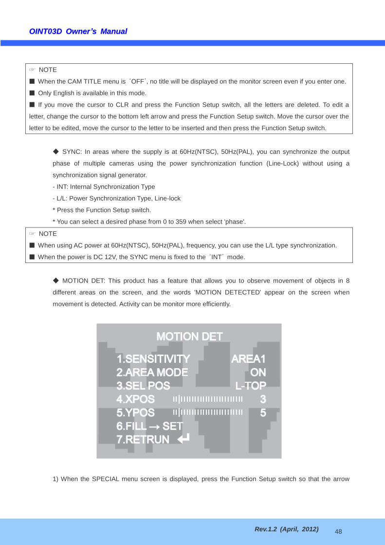
OOIINNTT0033DD OOwwnneerrrsquorsquoss MMaannuuaall
Rev12 (April 2012) 50
6-12 RETURN Setting
Select a desired RETURN mode using the Function Setup Switch
- SAVE Save the current settings and RETURN the MAIN SETUP menu
- NOT SAVE Do not save the current settings and RETURN the MAIN SETUP menu
- RESET Resets the camera settings to the factory defaults Language Communication and Monitor
Settings are not initialized