Embed Size (px)
Citation preview
Onshore pipeline Emergency Response Plan
Revision Number 03 Page 1 of 41
Date November 8th 2013 Printed copies are uncontrolled
Corrib Gas
Onshore pipeline
External Emergency Response Plan An Bord Pleanála Ref. 16.GA0004
Condition No. 11
DOCUMENT NO: COR 52-SH-0039B
Document Revision Record
Rev. Date Description Prepared Checked Approved
03 November 8th 2013
Final document Updated to reflect
final signed off document
SEPIL & PRA’s SEPIL & PRA’s SEPIL & PRA’s
02 October 2013
Updated to reflect public
consultation process
SEPIL & PRA’s SEPIL & PRA’s SEPIL & PRA’s
01 July 2013 Draft copy for
public consultation
SEPIL & PRA’s -
To be approved by PRA’s and SEPIL once consultation process
complete

Onshore pipeline Emergency Response Plan
Revision Number 03 Page 2 of 41
Date November 8th 2013 Printed copies are uncontrolled
Table of Contents
ABBREVIATIONS ......................................................................................................................... 4
PART ONE ....................................................................................................................... 5
SECTION 1 INTRODUCTION ...................................................................................................... 6
1.1 Background of the Plan ...................................................................................................... 6
1.2 Purpose of this document ................................................................................................... 6
1.3 Scope of the document ...................................................................................................... 7
1.4 Objectives of the document ................................................................................................ 7
1.5 When & by whom will the plan be activated ......................................................................... 7
PART TWO ...................................................................................................................... 8
SECTION 2 ONSHORE PIPELINE DETAILS ...................................................................................... 9
2.1 Location of the onshore pipeline .......................................................................................... 9
2.2 Pipeline fact sheet............................................................................................................ 10
2.3 Onshore umbilical ............................................................................................................ 10
2.4 Landfall Valve Installation ................................................................................................. 11
2.5 Major Accident Hazards {MAH} ......................................................................................... 13
2.6 Hydrocarbon release from the LVI ..................................................................................... 13
2.7 Hydrocarbon release from the onshore pipeline .................................................................. 14
PART THREE ................................................................................................................. 15
SECTION 3 MANAGEMENT OF EMERGENCY RESPONSE .................................................................... 16
3.1 Incident Categories .......................................................................................................... 16
3.2 Raising the alert .............................................................................................................. 17
3.2.1 Alert raised by SEPIL ..................................................................................... 17
3.2.2 Alert raised by a member of the public ............................................................ 19
3.2.3 Alert made aware to the Principal Response Agencies ...................................... 19
3.3 Command and Control and coordination of response ........................................................... 20
3.3.1 Command and Control Arrangements on location ............................................ 20
3.3.2 Co-ordination Arrangements ........................................................................... 20
3.3.3 The Lead Agency Concept: ............................................................................. 21
3.4 Roles and responsibilities .................................................................................................. 23
3.4.1 Roles and responsibilities of SEPIL Staff .......................................................... 23
3.4.2 Roles and responsibilities of An Garda Síochána .............................................. 24
3.4.3 Roles and responsibilities of the Health Service Executive................................. 25
3.4.4 Roles and responsibilities of the Local Authority ............................................... 26
3.5 On-site Emergency control centre ...................................................................................... 27
3.6 Scene Management .......................................................................................................... 28

Onshore pipeline Emergency Response Plan
Revision Number 03 Page 3 of 41
Date November 8th 2013 Printed copies are uncontrolled
3.6.2 Inner Cordon ................................................................................................. 28
3.6.3 Outer Cordon ................................................................................................ 29
3.6.4 Outer Cordon Access Point ............................................................................. 29
3.6.5 Traffic Cordons .............................................................................................. 29
3.7 Rendezvous Point (RVP) ................................................................................................... 30
3.8 Information to the public .................................................................................................. 32
3.8.1 How the public will be notified of an incident ................................................... 32
3.8.2 How the public will be kept informed .............................................................. 32
3.9 Telecommunications ........................................................................................................ 32
3.10 Hazardous Substances advice ........................................................................................ 32
3.11 Meteorological information ............................................................................................ 33
3.12 Recording events ......................................................................................................... 33
3.13 Cessation of emergency ................................................................................................ 33
3.14 Post Incident Review .................................................................................................... 33
3.15 Emergency response exercises ...................................................................................... 33
PART FOUR ................................................................................................................... 34
SECTION 4 TERMS AND DEFINITIONS ........................................................................................ 35
APPENDICES ................................................................................................................. 36
APPENDIX 1 DRAWINGS .......................................................................................................... 37
APPENDIX 2 LOCATION MAPS ................................................................................................... 38
APPENDIX 3 PRA’S PROTOCOL & SITE ARRANGEMENTS FOR RESPONDING ............................................ 41

Onshore pipeline Emergency Response Plan
Revision Number 03 Page 4 of 41
Date November 8th 2013 Printed copies are uncontrolled
Abbreviations
BA Breathing Apparatus
BBGT Bellanaboy Bridge Gas Terminal
BGN Bord Gais Network
COSHH Control of Substances Hazardous to Health
ECT Emergency Coordination Team
E&P Exploration & Production
ESB Electricity Supply Board
HSA Health and Safety Authority
HSE Health Services Executive
HSSE Health, Safety, Security and Environment
IS Intrinsically Safe
LRT Location Response Team
LVI Landfall Valve Installation
MAH Major Accident Hazards
Mayo Co. Co Mayo County Council
PRA Principal Response Agency (HSE Ambulance Service, An Garda Síochána & Fire Services)
RTA Road Traffic Accident
RVP Rendezvous Point
SEPIL Shell Exploration & Production Ireland Limited

Onshore pipeline Emergency Response Plan
Revision Number 03 Page 5 of 41
Date November 8th 2013 Printed copies are uncontrolled
Part One

Onshore pipeline Emergency Response Plan
Revision Number 03 Page 6 of 41
Date November 8th 2013 Printed copies are uncontrolled
Section 1 Introduction
1.1 Background of the Plan This Plan has been developed as part of a wider process relating to the preparation of External
Emergency Response Plans associated with the Corrib project. The development of these plans
has involved ongoing meetings between representatives from:
Shell E&P Ireland Limited
An Garda Síochána, Belmullet
Health Services Executive
Mayo County Council
These meetings were arranged in order to set standard agreed procedures for the effective and
coordinated response in the event of a major accident associated with the LVI and onshore pipeline, including the control of traffic both of the emergency services and private vehicles.
This plan should be read and implemented in conjunction with
The Emergency Response Plans of the three principal response agencies {PRA’s}
in the area of jurisdiction.
1.2 Purpose of this document The purpose of this document is to set standard agreed procedures for the effective and
coordinated response in the event of a major accident.
This document will serve to fulfil the requirement of Condition No. 11 of the Planning Permission
for the onshore pipeline (An Bord Pleanála Ref. 16.GA0004).
Planning Condition 11 requires that:
“The onshore upstream pipeline shall not be operated for the purpose of bringing
gas onshore from the Corrib Gas Field until such time as an Emergency
Response Plan has been prepared by the undertaker, for the area between
Glengad, Rossport, Aghoos and Bellanaboy. The plan shall be agreed with An
Garda Síochána, the Health Service Executive and Mayo County Council and
shall comply with any requirements set down in the Major Emergency Plan for
the area. The plan shall include control of traffic close to the terminal, close to
the Landfall Valve Installation and in the vicinity of the route of the pipeline in
the event of a major accident. The preparation of the Emergency Response Plan
shall include consultation with the public on the details to be contained in the plan.”

Onshore pipeline Emergency Response Plan
Revision Number 03 Page 7 of 41
Date November 8th 2013 Printed copies are uncontrolled
1.3 Scope of the document The scope of this document relates to emergency events associated with the LVI and onshore pipeline only.
1.4 Objectives of the document
To ensure the protection of people and the environment through the effective co-
ordination of emergency response by the principal response agencies.
To ensure for a coordinated response in the event of an emergency
1.5 When & by whom will the plan be activated WHEN: This plan may be activated when an incident occurs which is associated with the LVI and onshore
pipeline which: Is beyond the normal capabilities of the SEPIL Location Response Team & SEPIL
Emergency Coordination Team
AND/OR Is an incident which requires any external emergency services support
BY WHOM: This Plan may be activated by any of the following duty personnel:
The SEPIL Location Response Team “Site Main Controller” {SEPIL} located at the BBGT
The Emergency Coordination Team on duty “Emergency Coordinator” {SEPIL}
Any of the Authorised Officers of each of the individual Principal Response Agencies
The principal response agencies also have their own Major Emergency Plans, which would be activated in the event of a major Emergency. In the case of the Health Services Executive this is
their “HSE West Area Plan”.
Upon activation of this plan the Emergency Services will implement their key actions as outlined
in Sections 3.4.2 to 3.4.4 of this document.

Onshore pipeline Emergency Response Plan
Revision Number 03 Page 8 of 41
Date November 8th 2013 Printed copies are uncontrolled
Part Two
Onshore pipeline Emergency Response Plan
Revision Number 03 Page 9 of 41
Date November 8th 2013 Printed copies are uncontrolled
Section 2 Onshore pipeline details
2.1 Location of the onshore pipeline
For the purposes of this document the onshore pipeline commences at the LVI and traverses the
Glengad headland, in an east-south-easterly direction, for approximately 640m. The pipeline then
proceeds for approximately 4.9km within a dedicated tunnel in generally a south easterly direction beneath Sruwaddacon Bay. The end of the tunnel is situated near Aghoose, where the
pipeline route turns in an easterly direction for approximately 0.9km, traversing an area of blanket bog and including a crossing of an estuarine river channel. The route then enters an
area of forested bog (approximately 2.2km long) where it turns in a southerly direction, at the crossing of the L1202, and continues to the BBGT site.
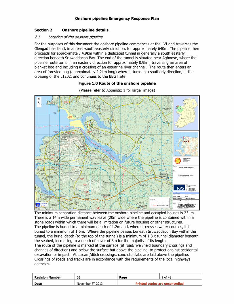
Figure 1.0 Route of the onshore pipeline
(Please refer to Appendix 1 for larger image)
The minimum separation distance between the onshore pipeline and occupied houses is 234m. There is a 14m wide permanent way leave (20m wide where the pipeline is contained within a
stone road) within which there will be a limitation on future housing or other structures. The pipeline is buried to a minimum depth of 1.2m and, where it crosses water courses, it is
buried to a minimum of 1.6m. Where the pipeline passes beneath Sruwaddacon Bay within the
tunnel, the burial depth (to the top of the tunnel) is a minimum of 1.3 x tunnel diameter beneath the seabed, increasing to a depth of cover of 8m for the majority of its length.
The route of the pipeline is marked at the surface (at road/river/field boundary crossings and changes of direction) and below the surface but above the pipeline, to protect against accidental
excavation or impact. At stream/ditch crossings, concrete slabs are laid above the pipeline. Crossings of roads and tracks are in accordance with the requirements of the local highways
agencies.
Onshore pipeline Emergency Response Plan
Revision Number 03 Page 10 of 41
Date November 8th 2013 Printed copies are uncontrolled
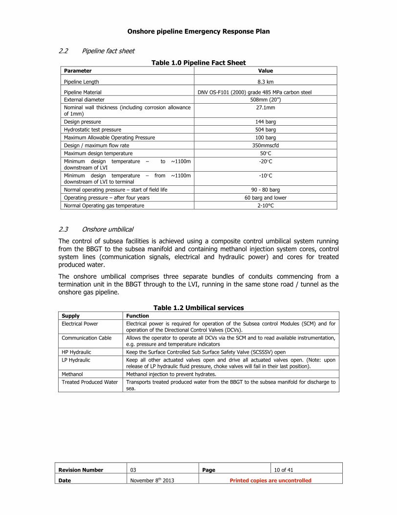
2.2 Pipeline fact sheet
Table 1.0 Pipeline Fact Sheet Parameter Value
Pipeline Length 8.3 km
Pipeline Material DNV OS-F101 (2000) grade 485 MPa carbon steel
External diameter 508mm (20”)
Nominal wall thickness (including corrosion allowance of 1mm)
27.1mm
Design pressure 144 barg
Hydrostatic test pressure 504 barg
Maximum Allowable Operating Pressure 100 barg
Design / maximum flow rate 350mmscfd
Maximum design temperature 50C
Minimum design temperature – to ~1100m downstream of LVI
-20C
Minimum design temperature – from ~1100m downstream of LVI to terminal
-10C
Normal operating pressure – start of field life 90 - 80 barg
Operating pressure – after four years 60 barg and lower
Normal Operating gas temperature 2-10°C
2.3 Onshore umbilical
The control of subsea facilities is achieved using a composite control umbilical system running
from the BBGT to the subsea manifold and containing methanol injection system cores, control
system lines (communication signals, electrical and hydraulic power) and cores for treated produced water.
The onshore umbilical comprises three separate bundles of conduits commencing from a termination unit in the BBGT through to the LVI, running in the same stone road / tunnel as the
onshore gas pipeline.
Table 1.2 Umbilical services
Supply Function
Electrical Power Electrical power is required for operation of the Subsea control Modules (SCM) and for operation of the Directional Control Valves (DCVs).
Communication Cable Allows the operator to operate all DCVs via the SCM and to read available instrumentation, e.g. pressure and temperature indicators
HP Hydraulic Keep the Surface Controlled Sub Surface Safety Valve (SCSSSV) open
LP Hydraulic Keep all other actuated valves open and drive all actuated valves open. (Note: upon release of LP hydraulic fluid pressure, choke valves will fail in their last position).
Methanol Methanol injection to prevent hydrates.
Treated Produced Water Transports treated produced water from the BBGT to the subsea manifold for discharge to sea.
Onshore pipeline Emergency Response Plan
Revision Number 03 Page 11 of 41
Date November 8th 2013 Printed copies are uncontrolled
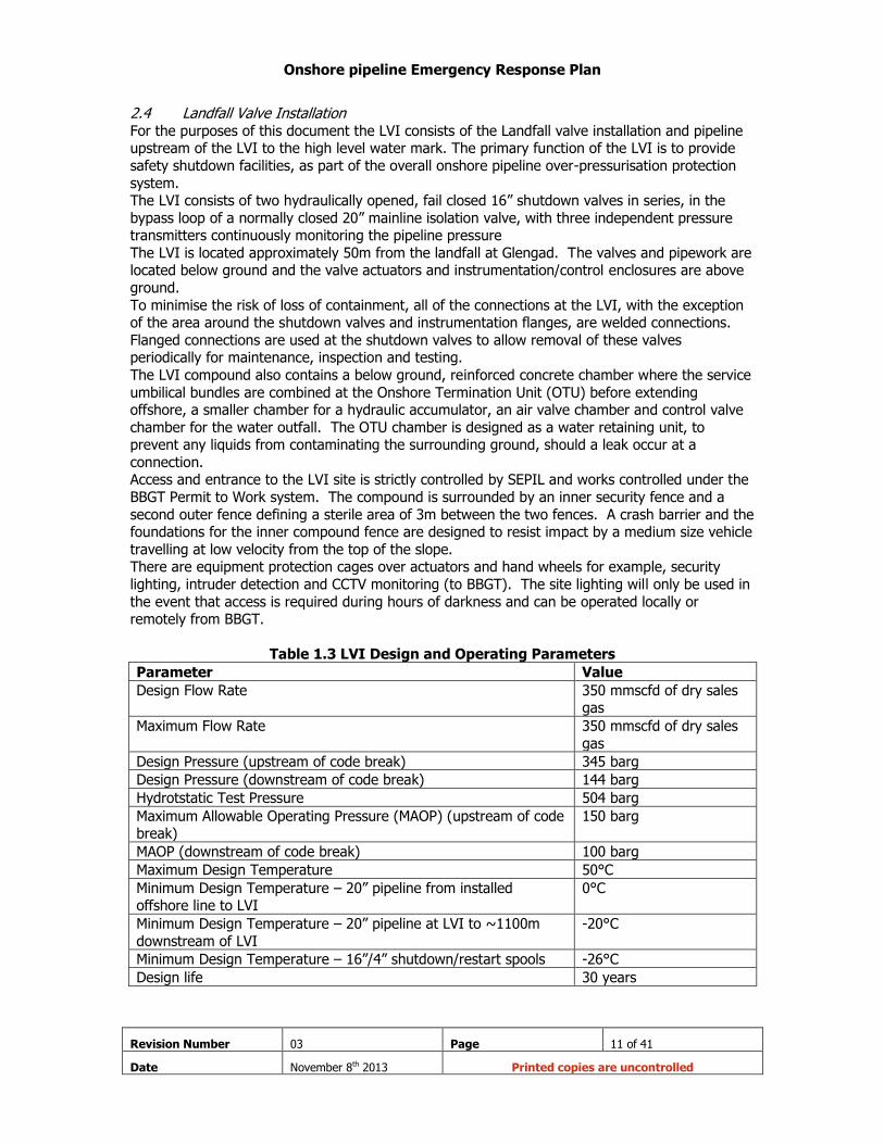
2.4 Landfall Valve Installation For the purposes of this document the LVI consists of the Landfall valve installation and pipeline upstream of the LVI to the high level water mark. The primary function of the LVI is to provide
safety shutdown facilities, as part of the overall onshore pipeline over-pressurisation protection
system. The LVI consists of two hydraulically opened, fail closed 16” shutdown valves in series, in the
bypass loop of a normally closed 20” mainline isolation valve, with three independent pressure transmitters continuously monitoring the pipeline pressure
The LVI is located approximately 50m from the landfall at Glengad. The valves and pipework are located below ground and the valve actuators and instrumentation/control enclosures are above
ground.
To minimise the risk of loss of containment, all of the connections at the LVI, with the exception of the area around the shutdown valves and instrumentation flanges, are welded connections.
Flanged connections are used at the shutdown valves to allow removal of these valves periodically for maintenance, inspection and testing.
The LVI compound also contains a below ground, reinforced concrete chamber where the service
umbilical bundles are combined at the Onshore Termination Unit (OTU) before extending offshore, a smaller chamber for a hydraulic accumulator, an air valve chamber and control valve
chamber for the water outfall. The OTU chamber is designed as a water retaining unit, to prevent any liquids from contaminating the surrounding ground, should a leak occur at a
connection. Access and entrance to the LVI site is strictly controlled by SEPIL and works controlled under the
BBGT Permit to Work system. The compound is surrounded by an inner security fence and a
second outer fence defining a sterile area of 3m between the two fences. A crash barrier and the foundations for the inner compound fence are designed to resist impact by a medium size vehicle
travelling at low velocity from the top of the slope. There are equipment protection cages over actuators and hand wheels for example, security
lighting, intruder detection and CCTV monitoring (to BBGT). The site lighting will only be used in
the event that access is required during hours of darkness and can be operated locally or remotely from BBGT.
Table 1.3 LVI Design and Operating Parameters
Parameter Value
Design Flow Rate 350 mmscfd of dry sales gas
Maximum Flow Rate 350 mmscfd of dry sales
gas
Design Pressure (upstream of code break) 345 barg
Design Pressure (downstream of code break) 144 barg
Hydrotstatic Test Pressure 504 barg
Maximum Allowable Operating Pressure (MAOP) (upstream of code break)
150 barg
MAOP (downstream of code break) 100 barg
Maximum Design Temperature 50°C
Minimum Design Temperature – 20” pipeline from installed offshore line to LVI
0°C
Minimum Design Temperature – 20” pipeline at LVI to ~1100m
downstream of LVI
-20°C
Minimum Design Temperature – 16”/4” shutdown/restart spools -26°C
Design life 30 years

Onshore pipeline Emergency Response Plan
Revision Number 03 Page 12 of 41
Date November 8th 2013 Printed copies are uncontrolled
Figure 1.2 Landfall Valve Installation Compound
Please refer to Appendix 1 for larger images of LVI
Onshore pipeline Emergency Response Plan
Revision Number 03 Page 13 of 41
Date November 8th 2013 Printed copies are uncontrolled
2.5 Major Accident Hazards {MAH}
There are two “Major Accident Hazards” associated with the onshore pipeline:
These are as follows:
Hydrocarbon release from Landfall Valve Installation;
Hydrocarbon release from onshore pipeline;
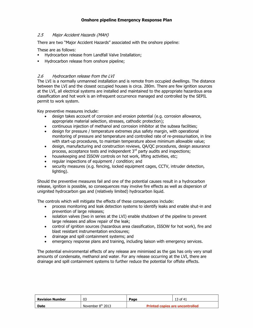
2.6 Hydrocarbon release from the LVI The LVI is a normally unmanned installation and is remote from occupied dwellings. The distance
between the LVI and the closest occupied houses is circa. 280m. There are few ignition sources at the LVI, all electrical systems are installed and maintained to the appropriate hazardous area
classification and hot work is an infrequent occurrence managed and controlled by the SEPIL
permit to work system.
Key preventive measures include: design takes account of corrosion and erosion potential (e.g. corrosion allowance,
appropriate material selection, stresses, cathodic protection);
continuous injection of methanol and corrosion inhibitor at the subsea facilities;
design for pressure / temperature extremes plus safety margin, with operational
monitoring of pressure and temperature and controlled rate of re-pressurisation, in line
with start-up procedures, to maintain temperature above minimum allowable value; design, manufacturing and construction reviews, QA/QC procedures, design assurance
process, acceptance tests and independent 3rd party audits and inspections;
housekeeping and ISSOW controls on hot work, lifting activities, etc;
regular inspections of equipment / condition; and
security measures (e.g. fencing, locked equipment cages, CCTV, intruder detection,
lighting).
Should the preventive measures fail and one of the potential causes result in a hydrocarbon release, ignition is possible, so consequences may involve fire effects as well as dispersion of
unignited hydrocarbon gas and (relatively limited) hydrocarbon liquid.
The controls which will mitigate the effects of these consequences include:
process monitoring and leak detection systems to identify leaks and enable shut-in and
prevention of large releases; isolation valves (two in series at the LVI) enable shutdown of the pipeline to prevent
large releases and allow repair of the leak;
control of ignition sources (hazardous area classification, ISSOW for hot work), fire and
blast resistant instrumentation enclosures;
drainage and spill containment systems; and emergency response plans and training, including liaison with emergency services.
The potential environmental effects of any release are minimised as the gas has only very small
amounts of condensate, methanol and water. For any release occurring at the LVI, there are drainage and spill containment systems to further reduce the potential for offsite effects.
Onshore pipeline Emergency Response Plan
Revision Number 03 Page 14 of 41
Date November 8th 2013 Printed copies are uncontrolled
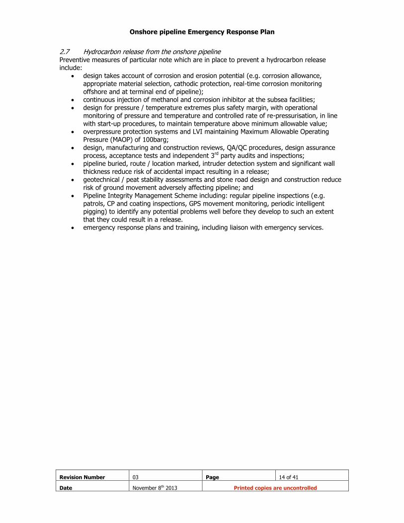
2.7 Hydrocarbon release from the onshore pipeline Preventive measures of particular note which are in place to prevent a hydrocarbon release include:
design takes account of corrosion and erosion potential (e.g. corrosion allowance,
appropriate material selection, cathodic protection, real-time corrosion monitoring
offshore and at terminal end of pipeline); continuous injection of methanol and corrosion inhibitor at the subsea facilities;
design for pressure / temperature extremes plus safety margin, with operational
monitoring of pressure and temperature and controlled rate of re-pressurisation, in line
with start-up procedures, to maintain temperature above minimum allowable value; overpressure protection systems and LVI maintaining Maximum Allowable Operating
Pressure (MAOP) of 100barg;
design, manufacturing and construction reviews, QA/QC procedures, design assurance
process, acceptance tests and independent 3rd party audits and inspections; pipeline buried, route / location marked, intruder detection system and significant wall
thickness reduce risk of accidental impact resulting in a release;
geotechnical / peat stability assessments and stone road design and construction reduce
risk of ground movement adversely affecting pipeline; and
Pipeline Integrity Management Scheme including: regular pipeline inspections (e.g.
patrols, CP and coating inspections, GPS movement monitoring, periodic intelligent pigging) to identify any potential problems well before they develop to such an extent
that they could result in a release. emergency response plans and training, including liaison with emergency services.

Onshore pipeline Emergency Response Plan
Revision Number 03 Page 15 of 41
Date November 8th 2013 Printed copies are uncontrolled
Part Three
Onshore pipeline Emergency Response Plan
Revision Number 03 Page 16 of 41
Date November 8th 2013 Printed copies are uncontrolled
Section 3 Management of Emergency Response
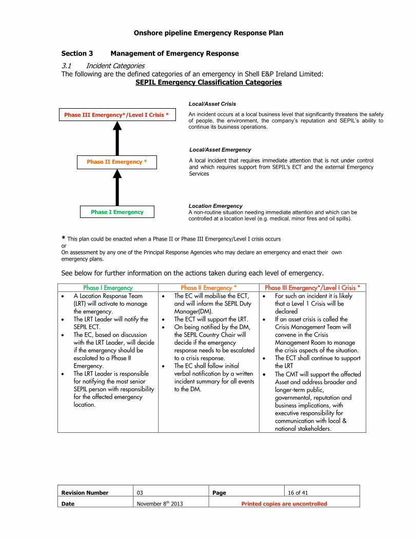
3.1 Incident Categories The following are the defined categories of an emergency in Shell E&P Ireland Limited:
SEPIL Emergency Classification Categories
* This plan could be enacted when a Phase II or Phase III Emergency/Level I crisis occurs
or On assessment by any one of the Principal Response Agencies who may declare an emergency and enact their own emergency plans.
See below for further information on the actions taken during each level of emergency.
Phase I Emergency Phase II Emergency * Phase III Emergency*/Level I Crisis * A Location Response Team
(LRT) will activate to manage the emergency.
The LRT Leader will notify the SEPIL ECT.
The EC, based on discussion with the LRT Leader, will decide if the emergency should be escalated to a Phase II Emergency.
The LRT Leader is responsible for notifying the most senior SEPIL person with responsibility for the affected emergency location.
The EC will mobilise the ECT, and will inform the SEPIL Duty Manager(DM).
The ECT will support the LRT. On being notified by the DM,
the SEPIL Country Chair will decide if the emergency response needs to be escalated to a crisis response.
The EC shall follow initial verbal notification by a written incident summary for all events to the DM.
For such an incident it is likely that a Level 1 Crisis will be declared
If an asset crisis is called the Crisis Management Team will convene in the Crisis Management Room to manage the crisis aspects of the situation.
The ECT shall continue to support the LRT
The CMT will support the affected Asset and address broader and longer-term public, governmental, reputation and business implications, with executive responsibility for communication with local & national stakeholders.
Phase I Emergency
Phase III Emergency*/Level I Crisis *
Phase II Emergency *
Location Emergency A non-routine situation needing immediate attention and which can be controlled at a location level (e.g. medical, minor fires and oil spills).
Local/Asset Emergency
A local incident that requires immediate attention that is not under control and which requires support from SEPIL’s ECT and the external Emergency Services
Local/Asset Crisis
An incident occurs at a local business level that significantly threatens the safety of people, the environment, the company’s reputation and SEPIL’s ability to continue its business operations.
Onshore pipeline Emergency Response Plan
Revision Number 03 Page 17 of 41
Date November 8th 2013 Printed copies are uncontrolled
3.2 Raising the alert
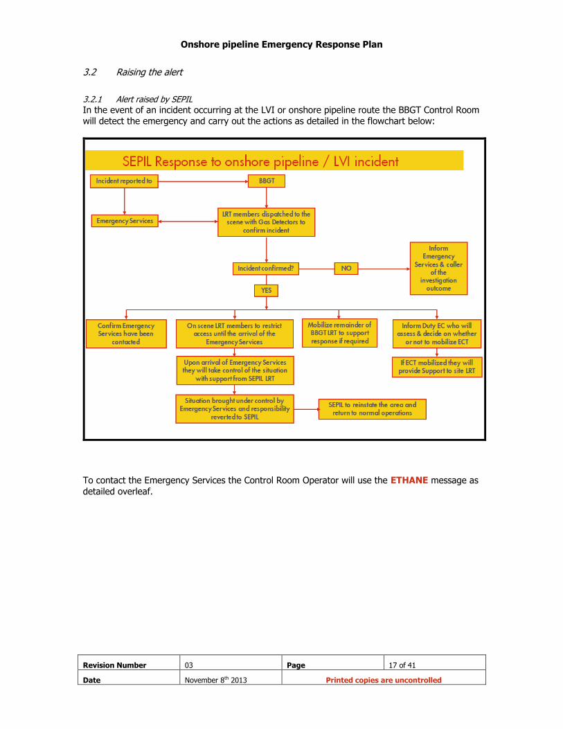
3.2.1 Alert raised by SEPIL
In the event of an incident occurring at the LVI or onshore pipeline route the BBGT Control Room will detect the emergency and carry out the actions as detailed in the flowchart below:
To contact the Emergency Services the Control Room Operator will use the ETHANE message as
detailed overleaf.
Onshore pipeline Emergency Response Plan
Revision Number 03 Page 18 of 41
Date November 8th 2013 Printed copies are uncontrolled
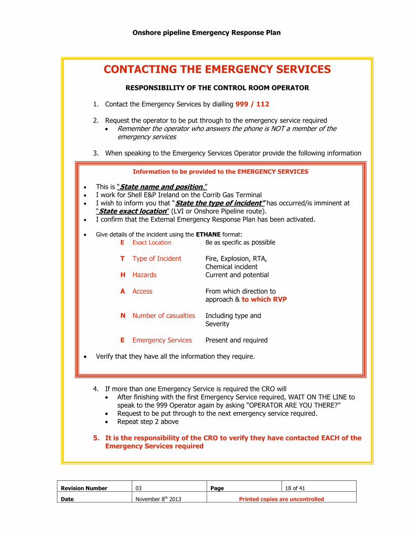
CONTACTING THE EMERGENCY SERVICES
RESPONSIBILITY OF THE CONTROL ROOM OPERATOR
1. Contact the Emergency Services by dialling 999 / 112
2. Request the operator to be put through to the emergency service required
Remember the operator who answers the phone is NOT a member of the emergency services
3. When speaking to the Emergency Services Operator provide the following information
4. If more than one Emergency Service is required the CRO will
After finishing with the first Emergency Service required, WAIT ON THE LINE to
speak to the 999 Operator again by asking “OPERATOR ARE YOU THERE?” Request to be put through to the next emergency service required.
Repeat step 2 above
5. It is the responsibility of the CRO to verify they have contacted EACH of the Emergency Services required
Information to be provided to the EMERGENCY SERVICES
This is “State name and position.” I work for Shell E&P Ireland on the Corrib Gas Terminal
I wish to inform you that “State the type of incident” has occurred/is imminent at “State exact location” (LVI or Onshore Pipeline route).
I confirm that the External Emergency Response Plan has been activated. Give details of the incident using the ETHANE format:
E Exact Location Be as specific as possible
T Type of Incident Fire, Explosion, RTA,
Chemical incident H Hazards Current and potential
A Access From which direction to approach & to which RVP
N Number of casualties Including type and
Severity
E Emergency Services Present and required
Verify that they have all the information they require.

Onshore pipeline Emergency Response Plan
Revision Number 03 Page 19 of 41
Date November 8th 2013 Printed copies are uncontrolled
3.2.2 Alert raised by a member of the public
In the event that a member of the public detects the incident they will contact the Emergency Services on 999 or 112. They may also contact the BBGT on +353 (0) 97 87 300
On discovery of an emergency situation: do not put yourself or others at risk;
raise the alarm by contacting the Emergency Services on 999 or 112.
3.2.3 Alert made aware to the Principal Response Agencies
Where the Principal response agency is the first to become aware of the incident they may
activate this plan through their own activation procedures as detailed in their own respective Major Emergency Plans and sub plans there under.
Once activated they will contact the other PRA’s and SEPIL and advise them accordingly with the
following message:
PRA’s Activation of the External Emergency Response Plan
“This is ……………….. (Name, rank and service) ……………..
A …..(Type of incident) …. has occurred/is imminent at the LVI or along the Onshore Pipeline route
of the Corrib Gas Project.
I confirm that the External Emergency Response Plan has been activated”

Onshore pipeline Emergency Response Plan
Revision Number 03 Page 20 of 41
Date November 8th 2013 Printed copies are uncontrolled
3.3 Command and Control and coordination of response
The phrases command, control and co-ordination are used to describe the hierarchy of relationships, and to establish decision-making arrangements. These terms have the meanings
assigned below:
Command – meaning the process of directing the operations of all or part of a particular
service (or group of services), by giving direct orders
Control – meaning the process of influencing the activity of a service or group of
services, by setting tasks, objectives or targets, but without the authority to give direct orders
Co-ordinate - meaning to bring the different elements of a complex activity or
organisation into an efficient relationship through a negotiated process. In an emergency
context this may include the mandate/authority to make certain decisions in pre-defined
areas, where a normal consensual approach does not appear to meet the needs of an emergency situation
Co-operate - meaning to work together towards the same end
Collaborate – meaning to work jointly on an activity.
3.3.1 Command and Control Arrangements on location
This section deals with command and control arrangements within individual services of the
principal response agencies, or other services responding to an emergency. It requires that:
Each principal response agency exercises command over its own resources in accordance with its normal command structure, command systems and arrangements;
Each principal response agency should exercise control over:
o Its own services operating at the site; and
o Other services (other than the other principal response agencies) which it
mobilises to the site;
The lead agency should exercise control over the services provided by any SEPIL
personnel.
3.3.2 Co-ordination Arrangements
In international best practice, the co-ordination of the efforts of all services is recognised as a vital element in successful response to emergencies. One of the key objectives is to set out the
arrangements and facilities for effective co-ordination of the individual response efforts of the principal response agencies to emergencies, so that the combined result is greater than the sum
of their individual efforts.
The key to achieving this objective is to recognise co-ordination of response as a specific function in emergency management.

Onshore pipeline Emergency Response Plan
Revision Number 03 Page 21 of 41
Date November 8th 2013 Printed copies are uncontrolled
3.3.3 The Lead Agency Concept:
The lead agency should be identified and assigned the responsibility and mandate for the co-ordination function in local emergencies. One of the three principal response agencies will be
designated as the lead agency for any emergency and thereby assume responsibility for leading co-ordination. In general, therefore, while the responsibility for co-ordination may be shared, in
any given situation responsibility for leading cooperation belongs specifically to one of the three
principal response agencies. The lead agency has both the responsibility and mandate for the co-ordination function.
The mechanisms for determining and designating the lead agency in any situation are set out below. Two mechanisms, which should be applied in sequence, are envisaged to determine the
lead agency for any emergency.
1. The first is by pre-nomination for common incident types and this should be the primary basis for determining the lead agency.
2. The second is a default arrangement, where the categorisations in the Table below (Extract from Mayo County Council Major Emergency Plan) do not seem to apply and the lead agency
is not obvious. In these situations, which should be rare, the Local Authority (Fire Services) will be the “default” lead agency.
Table: Pre-nominated Lead Agencies for Different Categories of Emergency
Emergency Incident Type Initial Pre-nominated Lead Agency
Likely change
Road Traffic Accident (1) An Garda Síochána To Mayo Fire Brigade when involving Hazardous Materials
Hazardous Material Local Authority (2)
Fire Local Authority
Train Crash Local Authority To An Garda Síochána when rescue phase complete
Aircraft Incident Local Authority To An Garda Síochána when fire-fighting / rescue phase complete
Rescue Local Authority
Weather Related Local Authority
Biological Incident Health Services
Open Country Search and Rescue (low land) An Garda Síochána
Open Country Search and Rescue (high land) An Garda Síochána(3)
Public order / Crowd Events An Garda Síochána
CCBRN(4),
Conventional(5),
Chemical, Biological
Radiological
Nuclear(6)
An Garda Síochána
Local Authority
Health Service Ex.
Local Authority
Local Authority
Accidental Explosions / Building Collapse Local Authority To An Garda Síochána to investigate when search and rescue completed
Environmental / Pollution Local Authority
Marine Emergency impacting on shore Local Authority (7)
Water Rescue inland An Garda Síochána(8)
{Notes associated with this table are detailed overleaf}

Onshore pipeline Emergency Response Plan
Revision Number 03 Page 22 of 41
Date November 8th 2013 Printed copies are uncontrolled
Notes:
(1) Road traffic accident in this context excludes Road Traffic accidents involving Hazardous Materials (other than fuel in vehicles).
(2) As its principal emergency service, the fire service is assigned initial responsibility for each
category where Mayo County Council is designated as lead agency, as it is likely to be the first attendance of that agency at the site. This may become a broader Local Authority function at a
later stage of the major emergency.
(3) An Garda Síochána may be assisted by specialist groups, such as Mountain Rescue teams.
(4) Where terrorist involvement is suspected, An Garda Síochána should assume the lead role, regardless of the agent. Should it subsequently transpire that there is no terrorist involvement;
the lead agency may change as indicated above.
(5) The Defence Forces, when requested, will assist An Garda Síochána, in an Aid to the Civil Power role, with Explosive Ordnance Disposal (EOD) teams, at suspected terrorist incidents.
Additional Defence Forces support in an Aid to the Civil Power role may be sought, if required.
(6) It is envisaged that Local/Regional involvement would arise only on foot of activation under
the National Emergency Plan for Nuclear Accidents (NEPNA).
(7) The Irish Coast Guard has responsibility for co-ordinating response to marine emergencies at sea. The Irish Coast Guard may, in certain circumstances, request the principal emergency
services to assist them offshore. When the Irish Coast Guard request the declaration of a major emergency, where casualties are being brought ashore (or pollution is coming, or threatening to
come ashore), the onshore response will be co-ordinated by Mayo County Council.
(8) The Irish Coast Guard has responsibility for receiving 999/112 calls and the mobilising of
resources to Inland Waterway emergencies. The Framework provides that An Garda Síochána
should be the principal response agency to undertake initial co-ordination at inland waterway emergencies. After the initial response, this role may be re-assigned, following consultation
between the Irish Coast Guard and An Garda Síochána.
Onshore pipeline Emergency Response Plan
Revision Number 03 Page 23 of 41
Date November 8th 2013 Printed copies are uncontrolled
3.4 Roles and responsibilities The roles and responsibilities of the PRA’s as set out below are in accordance with the Major Emergency Management Framework and the Major Emergency Plans of the principal response
agencies (in the case of the Health Services Executive this is their “HSE West Area Plan”).
3.4.1 Roles and responsibilities of SEPIL Staff
Site Main Controller
The Site Main Controller will ensure the activation of this document is complete – see 3.2
above on raising the alert
The Site Main Controller will initiate the BBGT Emergency Response Management System
The Site Main Controller will ensure the local residents have been informed
The Site Main Controller will inform the relevant regulators as required – contact details
contained in the BBGT Emergency Response Management System document
Control Room Operator (CRO)
The CRO will contact ALL required Emergency services and confirm to the Site Main
Controller that this has been completed.
The CRO will ensure the primary Rendezvous Point {RVP} is identified and communicated
to the Emergency Services. Please refer to section 3.7 on RVP’s
Onshore pipeline Emergency Response Plan
Revision Number 03 Page 24 of 41
Date November 8th 2013 Printed copies are uncontrolled
3.4.2 Roles and responsibilities of An Garda Síochána
An Garda Síochána should undertake the following functions in the response to a major
emergency: Declaration of a Major Emergency and notifying the other two relevant principal response
agencies
Activation of predetermined procedures/arrangements in accordance with its Major
Emergency Mobilisation Procedure
Requesting assistance from the Defence Forces in line with agreed protocols
Acting as lead agency, where this is determined in accordance with section 3.3.3 above
and undertaking the specified co-ordination function Maintaining law and order
Implementing agreed site plan/management arrangements, as appropriate
Traffic management
Crowd control
Implementing agreed aspects of evacuation procedures
Informing the public, as necessary and on the advice of the competent authorities, of
actual or potential dangers arising from the emergency
Coordinating/conducting searches for missing persons
Assisting and directing survivors/uninjured persons away from the site (and any danger
area) to places of safety Collecting information on casualties and survivors
Arrangements in respect of the dead, in association with the Coroner
Recovery of bodies
Provision of casualty bureaux/casualty information service
Preservation of the site
Collection of evidence and forensic work
Assisting the Coroner in the case of fatal casualties, inquiries or criminal proceedings
Engaging any specialist contractors required to assist with emergency operations
Exercising control of any voluntary or other service which it mobilises to the site
Monitoring and/or reporting on the impact in its functional area of any emergency/crisis
which falls within the ambit of a “National Emergency”, and undertaking any
countermeasures in its functional area which are required/recommended by an appropriate national body
Any other function, related to its normal functions, which is necessary for the
management of the emergency/crisis
Any function which the On-Site Co-ordinating Group requests it to perform
Maintaining essential Garda services during the Major Emergency.

Onshore pipeline Emergency Response Plan
Revision Number 03 Page 25 of 41
Date November 8th 2013 Printed copies are uncontrolled
3.4.3 Roles and responsibilities of the Health Service Executive
The Health Service Executive should undertake the following functions in the response to a major
emergency: -
Declaration of a Major Emergency and notifying the other two relevant principal response
agencies
Activation of predetermined procedures/arrangements in accordance with its Major
Emergency Mobilisation Procedure Acting as lead agency where this is determined in accordance with section 3.3.3 above
and undertaking the specified coordination function
Provision of medical advice and assistance
Provision of medical aid to casualties at the site
Triage of casualties, and assigning them to hospitals for evacuation
Casualty evacuation and ambulance transport
Provision of hospital treatment
Provision of psycho-social support to persons affected by the emergency
Certification of the dead
Support for An Garda Síochána’s forensic work
Support for the Coroner’s role
Clinical decontamination and decontamination of contaminated persons on arrival at
hospital Advising and assisting An Garda Síochána and Local Authorities on public health issues
arising
Exercising control of any voluntary or other service which it mobilises to the site
Monitoring and/or reporting on the impact in its functional area of any emergency/crisis
which falls within the ambit of a “National Emergency”, and coordinating/undertaking any countermeasures in its functional area which are required/recommended by an
appropriate national body
Any other function, related to its normal functions, which is necessary for the
management of the emergency/crisis Any function which the On-Site Co-ordinating Group requests it to perform
Maintaining essential health services during the Major Emergency.

Onshore pipeline Emergency Response Plan
Revision Number 03 Page 26 of 41
Date November 8th 2013 Printed copies are uncontrolled
3.4.4 Roles and responsibilities of the Local Authority
The Local Authority should undertake the following functions arising from the
Framework in the response to a major emergency: -
Declaration of a Major Emergency and notifying the other two relevant principal response
agencies Mobilisation of predetermined resources and activating predetermined procedures in
accordance with its Major Emergency Mobilisation Procedure
Acting as lead agency, where this is determined in accordance with section 3.3.3 above
above and undertaking the specified coordination function
Protection and rescue of persons and property
Controlling and/or extinguishing of fires
Dealing with hazardous material incidents including:
o Identification, containment, neutralisation and clearance of chemical spills and emissions
o Decontamination (other than clinical decontamination) on-site of persons affected (under medical supervision where necessary);
Advising on protection of persons threatened, by sheltering or evacuation;
Arranging/overseeing clean-up of affected areas;
Limiting damage to infrastructure and property;
Provision of access/transport to/from the site of the emergency;
Provision of additional lighting required, beyond what the principal emergency services
normally carry; Assisting An Garda Síochána to recover bodies, when requested;
Support for An Garda Síochána forensic work;
Support for the Coroner’s role, including provision of temporary mortuary facilities;
Accommodation and welfare of evacuees and persons displaced by the emergency;
Provision of food, rest and sanitary facilities as appropriate for personnel involved in the
response to the emergency;
Engaging any specialist contractors required to assist with emergency operations
Exercising control of any voluntary or other service which it mobilises to the site
Liaison with utilities regarding restoration/maintenance/or enhancing services provided to
the site or to persons affected
Site clearance, demolition, clear-up operations, removal and disposal of debris
Monitoring and/or reporting on the impact in its functional area of any emergency/crisis
which falls within the ambit of a “National Emergency”, and coordinating/undertaking any countermeasures in its functional area which are required/ recommended by an
appropriate national body Any other function, related to its normal functions, which is necessary for the
management of the emergency/crisis
Any function which the On-Site Co-coordinating Group requests it to perform
Maintaining essential Local Authority services (e.g. roads availability, fire and emergency
operations cover, public water supply, waste water treatment, waste disposal) during the major emergency.

Onshore pipeline Emergency Response Plan
Revision Number 03 Page 27 of 41
Date November 8th 2013 Printed copies are uncontrolled
3.5 On-site Emergency control centre
In the event of an emergency situation occurring at the LVI or onshore pipeline the on-site Location Response Team {LRT} will be mobilised to deal with the situation. The Location
Response Team leader is called the Site Main Controller. He/she will contact the on Duty SEPIL
Emergency Coordinator {SEPIL ECT Lead} who will decide whether or not to mobilise the ECT.
Location Response Team Structure for the BBGT & Associated facilities
The Site Main Controller manages the incident from the Control Room and directs the Site
Incident Controller who is based at the Forward Control Point at the scene of the emergency IF members of the Location Response Team are dispatched to the incident site.
Emergency Services
Control Room Operator
Emergency Services Site Main Controller
{Shift Supervisor}
Operators
(1 to act as Log keeper)
Main BA Rescue
Team Non-LRT Technicians
Forward Control Point
Site Incident Controller
Designated First Aiders
Security
Muster Controller & coordinators

Onshore pipeline Emergency Response Plan
Revision Number 03 Page 28 of 41
Date November 8th 2013 Printed copies are uncontrolled
3.6 Scene Management
The diagram below shows idealised scene management arrangements which apply for all emergencies involving PRA response. It details the requirements for effective scene management
i.e. establishing cordons (Inner, outer and traffic cordons), Holding areas for the PRA’s etc.
A number of cordons have been identified to aid in the control of emergency services vehicles
and private motor vehicles in the event of an incident being declared. These are described in further detail below.
3.6.2 Inner Cordon
For the LVI the Inner Cordon is defined by the double-fence line around the LVI and for the
onshore pipeline is dependent on the location of the incident and the RVP used to respond to the incident. The access point for the inner cordon at the LVI is the entrance to the LVI access road
from the L1202 which is manned by An Garda Síochána. Control of the inner cordon is by the Lead Agency.
The access point to an onshore pipeline inner cordon would be determined based on the location of the established inner cordon which is determined on a case by case basis depending on the
location of the incident.
Maps showing the location of the inner cordons are contained in Appendix 3 in “The Principal Response Agencies site arrangements for responding”
Onshore pipeline Emergency Response Plan
Revision Number 03 Page 29 of 41
Date November 8th 2013 Printed copies are uncontrolled
3.6.3 Outer Cordon
The Outer Cordon seals off an extensive area around the incident scene. The area between the Inner Cordon and Outer Condon is used by the PRAs to provide support to personnel within the
Inner Cordon. Control of the outer cordon is by the Lead Agency. Please see Appendix 3 “The Principal Response Agencies site arrangements for responding” for maps showing the location of
the outer cordons.
3.6.4 Outer Cordon Access Point
The Outer Cordon Access Points are controlled by An Garda Síochána (AGS). Please refer to Appendix 3 “The Principal Response Agencies site arrangements for responding” for maps
showing the locations of the outer cordons AGS access Points.
3.6.5 Traffic Cordons
The Traffic Cordon is similar to the Outer Cordon. However the purpose of the Traffic Cordon is to ensure free passage of emergency response vehicles into and out of the incident scene and to
prevent congestion at and around the incident scene. This Cordon is managed by An Garda Síochána.
RVP 1 Traffic Cordon
The traffic cordon for RVP1 was previously identified for the terminal site as the L1204, which
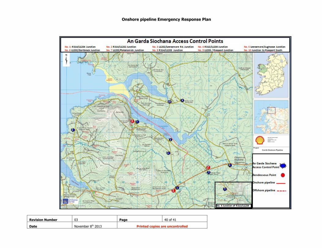
involved the positioning of an additional Garda at AGS#4 (See Appendix 2 for AGS Access control points). For the purposes of the onshore pipeline the traffic cordon for RVP1 would be the
triangle of roads around the terminal site manned primarily by AGS points 1, 2, 3 and 5 and if the need arises this could be extended to the L1204 to include AGS #4 near Bangor Erris.
An alternative Traffic Cordon, if required, can be arranged along the R314 leading East from the
site through Glenamoy and on into Ballina (junction with the N59). This will require the junction with the R315 at Ballycastle to be manned in addition to other locations on the R314 and N59.
RVP 2 Traffic Cordon
There are 2 traffic cordons associated with RVP 2
One is the triangle of roads around the terminal site manned primarily by AGS points 1,
2, 3, & 5.
A second cordon has been identified to cover the vicinity of Rossport manned by AGS
points 2, 8, 9 and 10.
RVP 3 Traffic Cordon
The LVI Traffic Cordon is the same as the Outer Cordon and requires that the L1202 be manned by AGS#6 & AGS#7.
Please refer to Appendix 3 “The Principal Response Agencies site arrangements for responding” for further details on the traffic cordons.

Onshore pipeline Emergency Response Plan
Revision Number 03 Page 30 of 41
Date November 8th 2013 Printed copies are uncontrolled
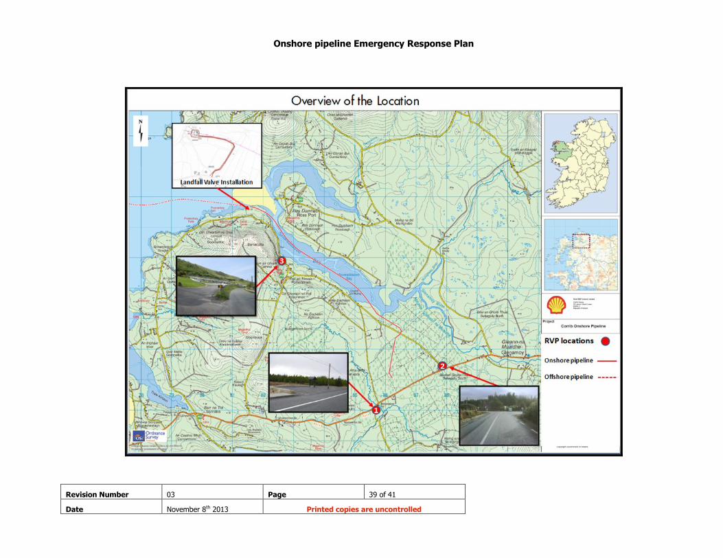
3.7 Rendezvous Point (RVP)
In the event of an Emergency the Control Room Operator, when contacting the Emergency Services, will direct the Emergency Services to RVP 1, 2 or 3 (Please refer to Appendix 2 for a
map showing the location of the RVP’s)
The Rendezvous Point is the location to which all resources responding to the emergency site are directed in the first instance. An Garda Síochána will organise the Rendezvous Point. Other
services may have one of their officers present to direct responding vehicles into action or to that service’s Holding Area.
Three Rendezvous Points have been identified for the LVI and onshore pipeline following a
review and visit to the area by the PRA’s. For any incident, only one point will be used. This
point will be selected based on the incident details and other factors including wind direction. In the event of an Emergency the Control Room Operator, when contacting the Emergency
Services, will direct the Emergency Services to RVP 1, 2 or 3.
To aid personnel responding to these locations, routes for each Rendezvous Point have been
identified and detailed directions are provided in Appendix 3 “The Principal Response Agencies site arrangements for responding”.
RVP1 is located at the lay-by adjacent to the junction of the L1204 and R314.
Rendezvous Point 1 (RVP1)

Onshore pipeline Emergency Response Plan
Revision Number 03 Page 31 of 41
Date November 8th 2013 Printed copies are uncontrolled
RVP 2 is located at the junction of R314 and L1202. It is located at least 1 km east of the Corrib
Gas terminal from Gate 1.
Rendezvous Point 2 (RVP2)
RVP 3 is located at the Pollatomish Graveyard car park 1.5Km past the entrance to the LVI.
Rendezvous Point 3 (RVP3)
Appendix 3 shows the predefined routes for each RVP, including access routes for each.
Onshore pipeline Emergency Response Plan
Revision Number 03 Page 32 of 41
Date November 8th 2013 Printed copies are uncontrolled
3.8 Information to the public
3.8.1 How the public will be notified of an incident
Residents in the surrounding area of the LVI and onshore pipeline route will receive initial contact
via the Shell Notification System from the Bellanaboy Bridge Gas Terminal informing them of the status of the situation.
Residents who have agreed to submit their telephone numbers will receive this initial alert via the
Shell Notification System which is a computer based system designed to reach people quickly, at the same time and with a consistent message.
Applicable residents are encouraged to participate in the system and submit their names and
contact numbers to SEPIL for inclusion on the system. The BBGT will also notify members of the
public of details regarding any other issues which need to be communicated to the public. Those members of the public not included in the system will be kept notified by the local radio
and other media sources.
The following information will be released to residents during an incident; Type of incident
Location and proximity of the incident to people in the vicinity
Actions to take
Actions being taken to correct the situation and time period anticipated
Contacts for additional information
3.8.2 How the public will be kept informed
The public will be kept informed by SEPIL and the responding agencies via any of the following:
Local {National as appropriate} radio broadcasts
Television broadcasts
Newspapers
Corrib Gas Website
RTE Aertel
Dedicated Emergency telephone number when provided by SEPIL
Local residents impacted may also be notified in person by SEPIL representatives
The “All Clear” (See Section 3.13 overleaf) will be notified to the public via the Shell Notification
System or via any of the means stated above.
3.9 Telecommunications The principal response agencies will use their standard means of telecommunications except where advised by Shell E&P Ireland Limited that only Intrinsically Safe telecommunication devices
should be used e.g. in the event of an unignited hydrocarbon release. In these instances Shell E&P Ireland Limited will provide intrinsically safe telecommunication
devices which will be stored at the BBGT.
3.10 Hazardous Substances advice Shell E&P Ireland will provide all necessary information concerning any hazardous substance involved in an incident related to its operations. i.e. material safety data sheets, Chemical Risk
Assessments. Copies of all Material Safety Data Sheets and chemical risk assessments will be available from the BBGT at all times.

Onshore pipeline Emergency Response Plan
Revision Number 03 Page 33 of 41
Date November 8th 2013 Printed copies are uncontrolled
3.11 Meteorological information Meteorological information will be obtained from dialling the 24hour Weatherdial number on 1550 123 852 {For Connaught}. Weather data is also available to the PRA’s from the BBGT Control
Room.
3.12 Recording events Each PRA maintains a log of events in line with their standard operating procedures.
3.13 Cessation of emergency A decision to stand down the emergency status of the incident should be taken by the Lead
Agency, in consultation with the other principal response Agencies and SEPIL. Activity may
continue at locations other than the scene of the incident (such as the hospitals, temporary mortuary, etc.) after the emergency is stood down at the location.
As the situation is brought under control, the resources on scene should be reviewed and reduced/stood down as necessary and in light of the changing situation. The Lead Agency
should be consulted before a decision is made to stand down any service.
The stand down of the enactment of this plan will be completed by the SEPIL Site Main Controller
in conjunction with the principal response agencies.
3.14 Post Incident Review Further to any incident occurring at the LVI or Onshore pipeline the SEPIL LRT will hold a post
incident review meeting. This meeting may include representatives from the PRA’s who may dial
into the meeting if unable to attend in person. In line with their standard procedures, each PRA will hold a post incident review meeting.
3.15 Emergency response exercises The public will be informed in advance of any major exercise of this plan.

Onshore pipeline Emergency Response Plan
Revision Number 03 Page 34 of 41
Date November 8th 2013 Printed copies are uncontrolled
Part Four

Onshore pipeline Emergency Response Plan
Revision Number 03 Page 35 of 41
Date November 8th 2013 Printed copies are uncontrolled
Section 4 Terms and definitions
Command The process of directing the operations of all or part of a
particular service (or group of services) by giving direct orders.
Control The process of influencing the activity of a service or group of services, by setting tasks, objectives or targets, without
necessarily having the authority to give direct orders.
Controller of Operations The person given authority by a principal response agency to control all elements of its activities at and about the site.
Holding Area An area at the site, to which resources and personnel, which are
not immediately required, are directed to await deployment.
Lead Agency The principal response agency that is assigned the responsibility
and mandate for the coordination function.
Principal Response The agencies designated by the Government to respond
Agencies (PRA’s) to Major Emergencies i.e. An Garda Síochána, the Health Service Executive and the Local Authorities.
Rendezvous Point (RVP) The Rendezvous Point is the location to which all resources responding to the emergency site are directed in the first
instance and is not an assembly point for mustering members of
the public. An Garda Síochána will organize the Rendezvous Point. Other services may have one of their officers present to
direct responding vehicles into action or to that service’s Holding Area.

Onshore pipeline Emergency Response Plan
Revision Number 03 Page 36 of 41
Date November 8th 2013 Printed copies are uncontrolled
Appendices
Onshore pipeline Emergency Response Plan
Revision Number 03 Page 37 of 41
Date November 8th 2013 Printed copies are uncontrolled
Appendix 1 Drawings
Drawings showing the route of the onshore pipeline
Drawings showing the location and layout of the LVI

Onshore pipeline Emergency Response Plan
Revision Number 03 Page 38 of 41
Date November 8th 2013 Printed copies are uncontrolled
Appendix 2 Location Maps
Onshore pipeline Emergency Response Plan
Revision Number 03 Page 39 of 41
Date November 8th 2013 Printed copies are uncontrolled
Onshore pipeline Emergency Response Plan
Revision Number 03 Page 40 of 41
Date November 8th 2013 Printed copies are uncontrolled

Onshore pipeline Emergency Response Plan
Revision Number 03 Page 41 of 41
Date November 8th 2013 Printed copies are uncontrolled
Appendix 3 PRA’s Protocol & site arrangements for responding