Embed Size (px)
Citation preview

CITY OF TEMECULA
ONLINE STANDARD PHOTOVOLTAIC PLANS
PV-1A
SINGLE INVERTER
Please make sure to download the latest standard plans from the City’s website.
2019 Code
Updated 01/27/2020
41000 Main Street Temecula, CA 92590 951-694-6476 TemeculaCA.gov/build [email protected]
Building Permit
Application
CD-1 Rev. 07/24/18 X:\Building & Safety\Forms_ Handouts\CD Forms\CD_1_Building_Permit\CD_1_Building_Permit.docx
Project Information: Jobsite Address (include Bldg. / Suite #):
OF
FIC
IAL
US
E O
NL
Y Permit #1:
Permit #2:
Map & Lot Number / Assessor’s Parcel (APN) #:
Permit #3: PRJ #: PA#:
Business Name (for commercial use only):
Type of Business:
Description of Proposed Work (include all areas): SQ. FT.:
Valuation:
Work Includes: Mechanical Electrical Plumbing Structural Property Owner’s Name:
Mailing Address:
Phone:
Applicant/Agent/Contractor Information:
Applicant/Agent Contractor Owner/Builder
City Business License #:
Contractor’s License #:
Primary Contact:
Email:
Phone:
Company/Firm Name:
Mailing Address:
Phone:
Architect/Engineer’s Name:
Mailing Address:
Phone:
Clearances: The following will be required prior to permit issuance. Fees may be required for these clearances.
1 Building & Safety [email protected] or (951) 694-6476
2 CR&R (required trash disposal service for all construction debris) (800) 755-8112
3 Fire Dept. (sprinkler system, driveway approaches, etc.) (951) 694-6405
4 Planning (project approvals, etc.) (951) 694-6400
5 Land Development (grading plan, encroachments, etc.) (951) 308-6395
6 Eastern Municipal Water District (EMWD) (sewer and/or water) (951) 928-3777 x2081
7 Rancho Calif. Water District (RCWD) (sewer and/or water) (951) 296-6900 x5202
8 Riverside County Health Dept. (septic system) (951) 955-8980
9 Environmental Health Dept. (food prep., public pools, etc.) (951) 461-0284
10 Temecula Valley Unified School District (TVUSD) (951) 506-7925
11 Agent/Employee Authorization when representing the Contractor
12 Electrical contractor is required for any commercial project (owner/builders)
13 Homeowner’s Association (HOA) – check HOA CC&R’s
14 Pre-construction meeting to be scheduled at issuance (new homes/commercial)
15 Owner/Builder Form/Letter of Authorization for Owner Builder Projects (notarization is required for commercial projects)
SIGNATURE OF APPLICANT: DATE:
The Community Development Technician will contact the applicant when the plans are ready for corrections or issuance.

DISABILITY ACCESS REQUIREMENTS AND RESOURCES NOTICE TO APPLICANTS FOR BUSINESS LICENSES AND COMMERCIAL BUILDING PERMITS:
Under federal and state law, compliance with disability access laws is a serious and significant responsibility that applies to all California building owners and tenants with buildings open to the public. You may obtain information about your legal obligations and how to comply with disability access laws at the following agencies:
DEPARTMENT OF GENERALSERVICES, Division of the State Architect, CASp
Program www.dgs.ca.gov/dsa www.dgs.ca.gov/casp
DEPARTMENT OF REHABILITATION Disability Access Services
www.dor.ca.govwww.rehab.cahwnet.gov/disabilityaccessinfo
DEPARTMENT OF GENERALSERVICES, California Commission on Disability Access
www.ccda.ca.gov www.ccda.ca.gov/resources-menu/
Certified Access Specialist Inspection Services Compliance with state and federal construction-related accessibility standards ensures that public places are accessible and available to individuals with disabilities. Whether your business is moving into a newly constructed facility or you are planning an alteration to your current facility, by engaging the services of a Certified Access Specialist (CASp) early in this process you will benefit from the advantages of compliance and under the Construction-Related Accessibility Standards Compliance Act (CRASCA, Civil Code 55.51-55.545), also benefit from legal protections.Although your new facility may have already been permitted and approved by the building department, it is important to obtain CASp inspection services after your move-in because unintended access barriers and violations can be created, for example, placing your furniture and equipment in areas required to be maintained clear of obstructions. For planned alterations, a CASp can provide plan review of your improvement plans and an access compliance evaluation of the public accommodation areas of your facility that may not be part of the alteration.A CASp is a professional who has been certified by the State of California to have specialized knowledge regarding the applicability of accessibility standards. CASp inspection reports prepared according to CRASCA entitle business and facility owners to specific legal benefits, in the event that a construction-related accessibility claim is filed against them. To find a CASp, visit www.apps2.dgs.ca.gov/DSA/casp/casp_certified_list.aspx. Government Tax Credits, Tax Deductions and Financing State and federal programs to assist businesses with access compliance and access expenditures are available: Disabled Access Credit for Eligible Small Businesses FEDERAL TAX CREDIT—Internal Revenue Code Section 44 provides a federal tax credit for small businesses that incur expenditures for the purpose of providing access to persons with disabilities. For more information, refer to Internal Revenue Service (IRS) Form 8826: Disabled Access Credit at www.irs.gov.
STATE TAX CREDIT—Revenue and Taxation Code Sections 17053.42 and 23642 provide a state tax credit similar to the federal Disabled Access Credit, with exceptions. For more information, refer to Franchise Tax Board (FTB) Form 3548: Disabled Access Credit for Eligible Small Businesses at www.ftb.ca.gov.
Architectural and Transportation Barrier Removal Deduction FEDERAL TAX DEDUCTION—Internal Revenue Code Section 190 allows businesses of all sizes to claim an annual deduction for qualified expenses incurred to remove physical, structural and transportation barriers for persons with disabilities. For more information, refer to IRS Publication 535: Business Expenses at www.irs.gov. California Capital Access Financing Program STATE FINANCE OPTION—The California Capital Access Program (CalCAP) Americans with Disabilities Act (CalCAP/ADA) financing program assists small businesses with financing the costs to alter or retrofit existing small business facilities to comply with the requirements of the federal ADA. Learn more at www.treasurer.ca.gov/cpcfa/calcap/. Federal and State Legal Requirements on Accessibility for Individuals with Disabilities AMERICANS WITH DISABILITIES ACT OF 1990 (ADA) —The ADA is a federal civil rights law that prohibits discrimination against individuals with disabilities, and requires all public accommodations and commercial facilities to be accessible to individuals with disabilities. Learn more at www.ada.gov .CALIFORNIA BUILDING CODE (CBC)—The CBC contains the construction-related accessibility provisions that are the standards for compliant construction. A facility’s compliance is based on the version of the CBC in place at the time of construction or alteration. Learn more at www.bsc.ca.gov. LANGUAGES:
AVISO EN ESPAÑOL - PANSININ SA TAGALOG - 한국어로 알림 - THÔNG BÁO BẰNG TIẾNG VIỆT - 繁体中文注意事项 - 简体中文

CITY OF TEMECULA ELIGIBILITY CHECKLIST
FOR EXPEDITED SOLAR PHOTOVOLTAIC PERMITTING FOR ONE AND TWO FAMILY DWELLINGS
1. GENERAL REQUIREMENTS YES NO
A. System size is 10 kW AC CEC rating or less
B. The solar array is roof-mounted on one- or two family dwelling or accessory structure
C. The solar panel/module arrays will not exceed the maximum legal building height
D. Solar system is utility interactive and without battery storage
E. Permit application is completed, accurate, and attached
2. ELECTRICAL REQUIREMENTS
A. No more than four photovoltaic module strings are connected to each Maximum Power Point Tracking (MPPT) input where source circuit fusing is included in the inverter
1. No more than two strings per MPPT input where source circuit fusing is not included
2.Fuses (if needed) are rated to the series fuse rating of the PV module
3.No more than one non inverter-integrated DC combiner is utilized per inverter
B. For central inverter systems: no more than two inverters are utilized
C. The PV system is interconnected to a single-phase AC service panel of nominal 120/220 Vac with a bus bar rating of 225A or less
D. The PV system is connected to the load side of the utility dist. equipment, or has GMA
E. A Solar PV Standard Plan and supporting documentation is completed and attached
F. The system is equipped with approved relay switching per the City of Temecula
Ordinance to disconnect all power output at the sources, when the main meter is de-energized.
3. STRUCTURAL REQUIREMENTS
A. A completed structural criteria form is completed and supporting document is attached
(if required)
4. FIRE SAFETY REQUIREMENTS
A. Clear access pathways are provided
B. Fire classification solar system is provided
C. All required markings and labels are provided
D. A diagram of the roof layout with all panels, modules, clear access pathways and approximate locations of electrical disconnecting means and roof access points is completed and attached.
E. Elevation showing egress paths required at egress windows.
NOTE: 1. These criteria are intended for expedited solar permitting process.
2. IF ANY ITEMS ARE CHECKED NO, revise the design to fit within the Eligibility Checklist, otherwise
the permit application will go through the standard process and follow our standard review times.
Project Address:

MARKINGS SIMPLIFIED CENTRAL/STRING INVERTER SYSTEMS FOR ONE- AND TWO-FAMILY DWELLINGS
Module Level Rapid Shutdown
CEC 690.56(C)(1)(a)
OR
2019 California Electrical Code Articles 110.21, 690 and 705 require the following labels or markings be installed at these components of the photovoltaic system:
WARNING ELECTRIC SHOCK HAZARD. THE DC
CONDUCTORS OF THIS PHOTOVOLTAIC SYSTEM ARE UNGROUNDED AND MAY BE
ENERGIZED
WARNING INVERTER OUTPUT CONNECTION;
DO NOT RELOCATE THIS
OVERCURRENT DEVICE
CEC 690.31(G)(3) [Must be reflective and marked
on junction/combiner boxes and
conduit every 10’]
WARNING: PHOTOVOLTAIC
POWER SOURCE
J/Box
PV SYSTEM AC DISCONNECT
RATED AC OUTPUT CURRENT - ____AMPS
NORMAL OPERATING VOLTAGE ___VOLTS
M
A
C
D
C
WARNING DUAL POWER SOURCES
SECOND SOURCE IS PHOTOVOLTAIC SYSTEM
RATED AC OUTPUT CURRENT- ____AMPS AC
NORMAL OPERATING VOLTAGE ___VOLTS
WARNING ELECTRIC SHOCK HAZARD
TERMINALS ON BOTH LINE AND LOAD SIDES MAY BE ENERGIZED IN THE
OPEN POSITION
MAIN OCPD
PV POWER SOURCE DC DISCONNECT
MAXIMUM CIRCUIT CURRENT- ___ADC MAXIMUM SYSTEM VOLTAGE- ___VDC
CEC 705.12(B)(2) [Not required if panel board is rated not less
than sum of ampere ratings of all overcurrent
devices supplying it]
CEC 690.35(F)
[Only required for ungrounded systems]
CEC 690.54
CEC 690.53 & 690.7/690.8(A)
CEC 690.13(B) & CEC 110.21(B)
CEC 690.54 & CEC 705.12(B)(3)
WARNING ELECTRIC SHOCK HAZARD
IF A GROUND FAULT IS INDICATED, NORMALLY GROUNDED CONDUCTORS
MAY BE UNGROUNDED AND ENERGIZED
CEC 690.5(C)
[Normally already present on listed Inverters]
Informational note: ANSI Z535.4 provides guidelines for the design of safety signs and labels for application to products. A phenolic plaque with contrasting colors between the text and background would meet the intent of the code for permanency. No type size is specified, but 20 point (3/8”) should be considered the minimum. CEC 705.12 requires a permanent plaque or directory denoting all electric power sources on or in the premises.
PV OCPD
INVERTER
CEC 690.56(C)(1)(b)
CEC 690.56(C)(2) [IF more than one Rapid Shutdown Exists on
structure, provide placard per CEC 690.56(C)(2)]
String Level Rapid Shutdown
RAPID SHUTDOWN SWITCH FOR PV
Identify one of the accessible switches that
initiates Rapid Shutdown
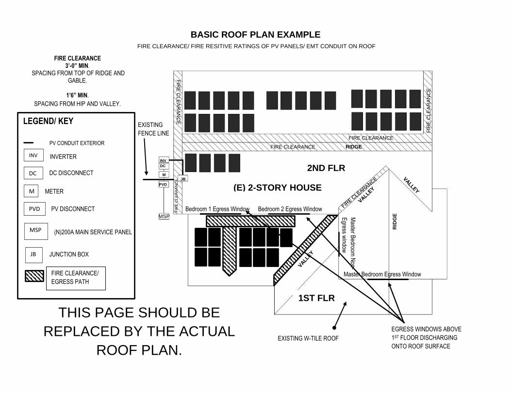
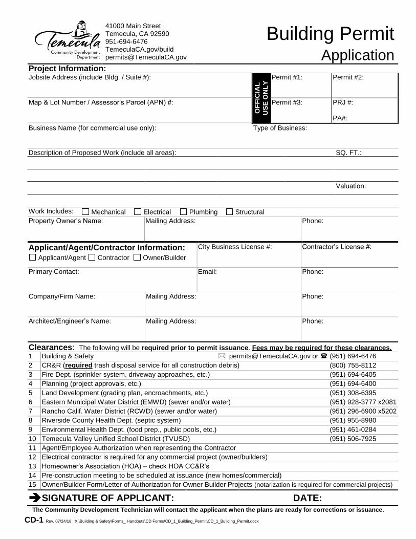
BASIC ROOF PLAN EXAMPLE
FIRE CLEARANCE/ FIRE RESITIVE RATINGS OF PV PANELS/ EMT CONDUIT ON ROOF
FIRE CLEARANCE
FIR
E C
LE
AR
AN
CE
FIR
E C
LE
AR
AN
CE
FIRE CLEARANCE
RID
GE
RIDGE
EXISTING W-TILE ROOF
MSP
PVD
M JB
DC
INV
FIR
E C
LE
AR
AN
CE
FIRE CLEARANCE 3’-0” MIN.
SPACING FROM TOP OF RIDGE AND GABLE.
1’6” MIN.
SPACING FROM HIP AND VALLEY.
(E) 2-STORY HOUSE
THIS PAGE SHOULD BE
REPLACED BY THE ACTUAL
ROOF PLAN.
Master Bedroom Egress Window
Master B
edroom N
on-
Egress w
indow
Bedroom 1 Egress Window Bedroom 2 Egress Window
LEGEND/ KEY
PV CONDUIT EXTERIOR
INV INVERTER
DC DC DISCONNECT
M METER
PVD PV DISCONNECT
MSP (N)200A MAIN SERVICE PANEL
JB JUNCTION BOX
EXISTING
FENCE LINE
FIRE CLEARANCE/
EGRESS PATH
EGRESS WINDOWS ABOVE
1ST FLOOR DISCHARGING
ONTO ROOF SURFACE
1ST FLR
ROOF
2ND FLR
ROOF

EGC SIZE FOR AC SIDE ____ AWG: Copper Sized per T250.122. All exposed EGC’s shall be #6 min per 250.120(C)
PV SOURCE CIRCUITS No. Entering Comb. Box AWG Conductor Type (Check One) THWN-2 Other: XHHW-2 EMT Conduit Size Number of current carrying conductors 2 4 6 8
PV SOURCE CIRCUITS No. Entering J-Box: ___ AWG: ___ Conductor Type (Check One): ___USE-2 ___PV WIRE
EGC PV EQUIPMENT GROUNDING (Check One) ____#8 AWG with lug listed for ground and direct burial. #8 solid copper shall be considered free from physical damage when run under the array. 250.120(C) ____WEEB clips; provided module manufacturer permits WEEB. Use #6 AWG from mounting structures to J-Box ____ Self-bonding rack system (Attach Cut Sheet) Brand Name of Racking System_____________
INVERTER INFO Make: _____________________ Model:_____________________ Input Volts DC: ______________ Max AC Output, Amps: _______ No. of fused inputs: __________ Fuse size used, Amps:________
AC DISC INFO Make: ____________________ Model: _____________________ Size, Amp: ___________
Project Address:
Property Owner’s Name:
COMBINER BOX INFO Used? Yes__ No__ Make: ____________________ Model: ____________________ Fuse size used, Amps: ____ (Listed by NRTL)
~~~~
AC
DC
MAIN OCPD
INVERTER OCPD
M
MAIN SERVICE PANEL
UTILITY SERVICE
BUSBAR (INTERNAL)
BUSBAR
_______MODULES IN SERIES
_______MODULES IN SERIES
_______MODULES IN SERIES
_______MODULES IN SERIES
M
ONE LINE DIAGRAM- STRING INVERTER (single Inverter system)
(PUT “N/A” IF UNUSED)
(PUT “N/A” IF UNUSED)
(PUT “N/A” IF UNUSED)
(PUT “N/A” IF UNUSED)
Roof Top DC Disconnect/Contactor/Rapid Shutdown/Optimizers
Make: ____________________ Model: ____________________ _____ #of Contactors Installed/ Rapid Shutdown units ___Yes OR ___No OR ___Not Req
= Equipment Information
BOX COLOR KEY:
= Circuit Information
= Grounding Information
J-BOX INFO (minimum: NEMA 3R) USED (Check One): ___Yes OR ___No
(E)XISTING BUILDING GROUNDING ELECTRODE or UFER IF NEW ELECTRODE: USE ¾” X 10’-0” LONG ROD BURIED MIN. 8’-0” IN SOIL PER 250.53(G) USE EXOTHERMIC WELDING PROCESS OR LISTED HIGH PRESS CONNECTOR TO BOND GEC TO ELECTRODE CONDUCTOR. ONE CONDUCTOR TO GE PER CONNECTION UNLESS CLAMP IS LISTED FOR MULTIPLE CONDUCTORS PER 250.70
CONDUIT HEIGHT ABOVE ROOFTOP: Must be more than 7/8” above roof or conductors require deration with Temp. adder of 33F/60C per 310.15(B)(3)(c)
See City of Temecula DC Rooftop Contactor Ordinance
PV-1A REV. 01/22/2020
MODULE INFO Make: Model: Voc, Volts: Isc, Amps: DC Optimizers Yes No
INVERTER OUTPUT CIRCUITS No. Leaving Inverter: ___ AWG: ___ Conductor Type (Check One): ___THWN-2 ___XHHW-2 ___ Other ____________
MAIN DIST PANEL INFO ____New ____Existing __GMA ____End Fed or ____Center Fed (check one) Bus Bar Rating, Amps: _______ Main OCPD, Amps: __________ Inverter OCPD: _________
CONDUIT MATERIAL USED (OUTPUT) ____Size DIA EMT fastened every 10 feet and within 3 feet of boxes, cabinets, and/or terminations per 358.30(A) and supported every 10 feet per 358.30(B); or, ____Size DIA PVC require expansion fittings and support straps attached to mounting surface with one fastener on each side of conduit per 352.30 and 352.44. NO PVC ON ROOF TOP
PV METER INFO
USED (Check One): ___Yes OR ___No
Combiner to Inverter Circuits No. of conductors Entering Inverter: ___ Conduit Size: _____ AWG: ____ # _____ AWG: ____ # _____ AWG: ____ # _____ AWG: ____ # _____ Conductor Type (Check One): ___THWN-2 ___XHHW-2(PV) ___# Strings Combined
EGC SIZE FOR DC SIDE (Check One) ____AWG: ____ Sized per T250.122. All exposed EGC’s shall be #6 min per 250.120(C) ____EMT bonded at each end of raceway where encountering eccentric or concentric knockouts per 250.97

PV CALCULATIONS WORKSHEET
1. Maximum System Voltage
VOC____ x ____ (largest string) x 1.12 = ____ < 600 V
2. Inverter Max Current Input (Inverter Specification)
SCC____ X 125% = ____X ___#String = ____ < or = to ____
3. Combiner to Inverter Conductor Sizing
SCC ____ X 125% x 125 % = ____ X (# strings if combined) = ____
4. Combiner to Inverter Conductor de-rating
A._____X B._____ X C._____ = _____ = or >_______
A. Conductor ampacity
B. Temp. adjustment factor for conduit above roof (.71 min. 1/2” - 3 1/2”)
C. Adjustment factor for more than 3 current carrying conductors in raceway . (4-6=80%) (7-9=70%) (10-20=50%)
5. Inverter Max output current spec. ____ X 125% = _____
6. Conductor size from inverter to Sub Panel or Main
____amps X .91 = ____= to or > ____
7. Conductor size from Sub Panel to Main Panel
____amps X .91 =_____ = to or > _____
Conductor ampacity X Ambient air temperature (.91 Max de-rate)
8. Conduit Fill
per Table C.1 DC ____AC____
9. Main Panel Solar Input Calculation
1. Main Panel Buss rating ______
2. Main Breaker ______
3. Solar Breaker ______ Max Allowable _______
4. Center Fed ______
5. End Fed ______
NOTES:
Solar breaker to be next size up, per Section 240.4B, 240.6, 690.8(A)(3) and 690.8(B)(1) of the
2019 CEC
Project Address:
Solar Edge with DC Power Optimizers
will be used (no worksheet required)
Micro inverter (no worksheet required)

PV CALCULATIONS WORKSHEET GUIDE
1. Maximum Photovoltaic System Voltage adjusted for lowest ambient temperature.
Code Sec (690.7)
2. Inverter maximum input adjusted for max output per Code Sec. (690.8 & 690.9)
3. Combiner to inverter conductor Ampacity/ Sizing per Code Sec. (690.8 & 690.9)
4. Combiner to inverter conductor de-rating Code Sec 310.15(B)(3)(a) and 310.15(B)(16) and Ambi-
ent 690.31(E), Rooftop Table 310.15 (b)(3)(c)
5. Inverter continuous max output calculation for conductor sizing and overcurrent device sizing. Code Sec (690.8)
6. Conductor sizing from Inverter to Load Center or Main Code Sec. (690.8 & 690.9) De-rating for ambient temperature only.
7. Same as #6 above
8. Conduit Fill calculations Annex C Table C.1
9. Main Panel Solar Input Calculation and Breaker Sizing 705.12(B)(2) and: 240.4(B), 240.6, 690.8 (3), 690.8(B)(1)
Project Address:

STRUCTURAL CRITERIA FOR RESIDENTIAL FLUSH-MOUNTED SOLAR ARRAYS
1. ROOF CHECKS YES NO
A. Visual review/contractor’s site audit of existing conditions
1. Is the roof a single roof without a reroof overlay?
2.Does the roof structure appear sound, without signs of alterations or significant structural deterioration or sagging? (see Figure 1*)
B. Roof Structure Data:
1. Measured roof slope (e.g. 6:12): :12
2. Measured rafter spacing (center-to-center): :inch(es)
3. Type of roof framing (rafter or manufactured trust): Rafter Truss
2. SOLAR ARRAY CHECKS
A. Flush-mounted solar array:
1. Is the plane of the modules (panels) parallel to the plane of the roof?
2. Is there a 2” to 10” gap between underside of module and the roof surface?
3. Modules do not overhang any roof edges (ridges, hops, gable ends, eaves)?
B. Do the modules plus support components weigh no more than 4 PSF for photovoltaic arrays or 5 PSF for solar thermal arrays?
C. Does the array cover no more than half of the total roof area (all roof planes)?
D. Are solar support component manufacturer’s project-specific completed worksheets, tables with relevant cells circled, or web-based calculator results attached?
E. Is a roof plan of the module and anchor layout attached? (see Figure 2*)
F. Downward load check (anchor layout check):
1. Proposed anchor horizontal spacing (see Figure 2*) ft. inch(es)
2. Horizontal anchor spacing per Table 1*: ft. inch(es)
3. Is the proposed anchor horizontal spacing equal to or less than Table 1* spacing?
G. Wind Uplift Check (Anchor Fastener Check):
1. Anchor fastener data (see Figure 3*):
a. Diameter of lag screw, hanger bolt, or self-drilling screw: inch(es)
b. Embedment depth of rafter inch(es)
c. Number of screws per anchor (typically one): screw(s)
d. Are 5/16” diameter lag screws with 2.5” embedment into the rafter used OR does the anchor fastener meet the manufacturer’s guidelines?
3. SUMMARY
A. All items above are checked YES. No additional structural calculations are required.
B. One or more items are checked NO. Attach project specific drawings and calculations stamped by a California licensed civil or structural engineer.
Project Address:
Contractor/Installer:
California License #: California License Class:
Signature: Date: Phone Number:
* Please refer to the California Solar Permitting Guidebook Structural Section for additional information. Website: http://opr.ca.gov/docs/20190226-Solar_Permitting_Guidebook_4th_Edition.pdf

STRUCTURAL CRITERIA FOR RESIDENTIAL FLUSH-MOUNTED SOLAR ARRAYS
TABLE 1. MAXIMUM HORIZONTAL ANCHOR SPACING
Roof Slope
Rafter pacing
16” o.c. 24” o.c. 32” o.c.
Photovoltaic Arrays(4 psf max)
Flat to 6:12 0° to 26° 5’-4” 6’-0” 5’-4”
7:12 to 12:12 27° to 45° 1’-4” 2’-0” 2’-8”
13:12 to 24:12 46° to 63° 1’-4” 2’-0” 2’-8”
Solar Thermal Arrays (5 psf max)
Flat to 6:12 0° to 26° 4’-0” 4’-0” 5’-4”
7:12 to 12:12 27° to 45° 1’-4” 2’-0” 2’-8”
13:12 to 24:12 46° to 63° Calculation Req. Calculation Req. Calculation Req.
Solar support component manufacturer’s guidelines may be relied upon to ensure the array above the roof is properly designed, but manufacturer’s guidelines typically do NOT check to ensure that the roof
itself can support the concentrated loads from the solar array. Table 1 assumes that the roof complied with the building code in effect at the time of construction, and places limits on anchor horizontal spacing to ensure that a roof structure is not overloaded under either downward loads or wind uplift loads. Note 4 below lists the basic assumptions upon which this table is based.
Table 1 Notes:
1. Anchors are also known as “stand-offs,” “feet,” “mounts” or “points of attachment.” Horizontal anchor spacing is also known as “cross-slope” or “east-west” anchor spacing (see Figure 2).
2. If anchors are staggered from row-to-row going up the roof, the anchor spacing may be twice that shown above, but no greater than 6’-0”.
3. For manufactured plated wood trusses at slopes of flat to 6:12, the horizontal anchor
spacing shall not exceed 4’-0” and anchors in adjacent rows shall be staggered.
4. This table is based on the following assumptions: • The roof structure conformed to building code requirements at the time it was built. • The attached list of criteria is met.
• Mean roof height is not greater than 40 feet. • Roof sheathing is at least 7/16” thick oriented strand board or plywood. 1x skip sheathing
is acceptable. • If the dwelling is in Wind Exposure B (typical urban, suburban or wooded areas
farther than 500 yards from large open fields), no more than one of the following conditions apply:
– The dwelling is located in a Special Wind Region with design wind speed between 115 and 130 mph per ASCE 7-10.
– The dwelling is located on the top half of a tall hill, provided average slope is less than 15%.
• If the dwelling is in Wind Exposure C (within 500 yards of large open fields or grasslands), all of the following conditions apply.
– Design wind speed is 110 mph or less (not in a Special Wind Region). – The dwelling is not located on the top half of a tall hill.
• The solar array displaces roof live loads (temporary construction loads) that the roof was originally designed to carry.
• The Structural Technical Appendix provides additional information about analysis assumptions.