Embed Size (px)
Citation preview
Doc. Version 1.0
Updated: 21-May-15
Copyright OneStop Reporting
OneStop Reporting
OSR ETL Tool 4.5
User Guide
Doc. Version 1.0
Updated: 21-May-15
Copyright OneStop Reporting
Contents
Introduction ..................................................................................................................................................... 1
Who Should Read this Manual ............................................................................................................................. 1
What’s included in this Manual............................................................................................................................ 2
Symbols and Conventions .................................................................................................................................... 2
Installation ........................................................................................................................................................... 2
OSR ETL Tool – Overview .................................................................................................................................. 3
Login ..................................................................................................................................................................... 3
Home Page ........................................................................................................................................................... 4
New ETL Process .......................................................................................................................................... 4
Existing ETL Processes .................................................................................................................................. 5
New/Existing ETL Tasks ................................................................................................................................ 5
User Access .................................................................................................................................................. 7
Recent and Status ........................................................................................................................................ 8
Settings ........................................................................................................................................................ 9
Create and Managing ETL Processes ............................................................................................................... 11
Creating a New ETL Process ............................................................................................................................... 12
Source Connection ..................................................................................................................................... 12
Target Connection ..................................................................................................................................... 13
Mappings and Status ................................................................................................................................. 13
Managing Existing ETL Processes ....................................................................................................................... 14
Creating and Managing ETL Mappings ............................................................................................................ 16
Creating a New ETL Mapping ............................................................................................................................. 16
Source and Target Object .......................................................................................................................... 17
Column Mapping ....................................................................................................................................... 18
Storage Options ......................................................................................................................................... 21
Source Filter ............................................................................................................................................... 21
Run the Mapping ....................................................................................................................................... 22
Managing ETL Mappings .................................................................................................................................... 23
Scheduling ETL Tasks ...................................................................................................................................... 24
New ETL Task ...................................................................................................................................................... 24
New Folder Based Task .............................................................................................................................. 25
New Scheduled Task .................................................................................................................................. 26
Existing ETL Tasks ............................................................................................................................................... 26
ETL Console ................................................................................................................................................ 26

Doc. Version 1.0
Updated: 21-May-15
Copyright OneStop Reporting
Appendix A – SQL Expression Codes ............................................................................................................... 28
Appendix B – Pre-ETL Setup and Checklist ...................................................................................................... 29
Appendix C – Creating an ETL Template (Under Construction) ....................................................................... 31
Appendix 1.0 – AX 2009 ETL Template ........................................................................................................... 32

OSR ETL Tool User Guide
_____________________________________________________________________________________________________
Page 1
Introduction
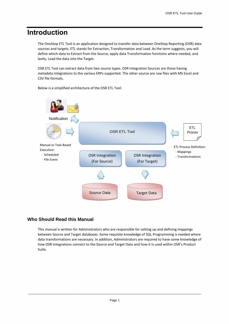
The OneStop ETL Tool is an application designed to transfer data between OneStop Reporting (OSR) data
sources and targets. ETL stands for Extraction, Transformation and Load. As the term suggests, you will
define which data to Extract from the Source, apply data Transformation functions where needed, and
lastly, Load the data into the Target.
OSR ETL Tool can extract data from two source types. OSR Integration Sources are those having
metadata integrations to the various ERPs supported. The other source are raw files with MS Excel and
CSV file formats.
Below is a simplified architecture of the OSR ETL Tool:
Who Should Read this Manual
This manual is written for Administrators who are responsible for setting up and defining mappings
between Source and Target databases. Some requisite knowledge of SQL Programming is needed where
data transformations are necessary. In addition, Administrators are required to have some knowledge of
how OSR Integrations connect to the Source and Target Data and how it is used within OSR’s Product
Suite.
OSR ETL Tool
Notification
Source Data
Manual or Task-Based
Execution:
- Scheduled
- File Event
ETL
Proces
ss
Target Data
OSR Integration
(For Source)
OSR Integration
(For Target)
ETL Process Definition:
- Mappings
- Transformations
OSR ETL Tool User Guide
_____________________________________________________________________________________________________
Page 2
What’s included in this Manual
This manual is designed to give an in-depth understanding of how to use the features of the OSR ETL
Tool. The manual is divided into the following parts:
Overview: Introduction to the OSR ETL Tool and functions
Detailed Descriptions: Detailed explanation of functionality and properties
Appendices: Technical prescriptions, ETL environment setup, and ETL Templates are
explained in-depth
Symbols and Conventions
This manual uses the following symbols to make specific types of information stand out.
Symbol Description
The sunlight symbol indicates helpful tips, shortcuts, and suggestions.
The warning symbol indicates situations we recommend to be aware of when
completing tasks. Typically, this includes caution regarding completing steps in their
proper order or important reminders about how other information in OSR may be
affected.
Installation
Please consult the OSR installation guide for details on installing the OSR application package.
The software can be downloaded from the Downloads area on www.onestopreporting.com.
The first time you go to Downloads you must register an account. You can then log in using the user
name and password you registered.
OSR ETL Tool User Guide
_____________________________________________________________________________________________________
Page 3
OSR ETL Tool – Overview
The OSR ETL Tool is an application for Administrators to setup and maintain ETL (Extract, Transform, &
Load) processes to transfer OSR Data Sources between Source and Target databases.
By OSR Data Sources, it means both the Source and Target data sources are defined by an OSR
Integration Package (see OSR Admin Tool documentation). You cannot connect the OSR ETL Tool directly
to a Source/Target database using ODBC or another formal connection protocol. Connections must be
established using a valid OSR Data Connection as defined using the OSR Administration Tool. This means
an OSR Data Connection can only be created with a valid and installed OSR Integration Package.
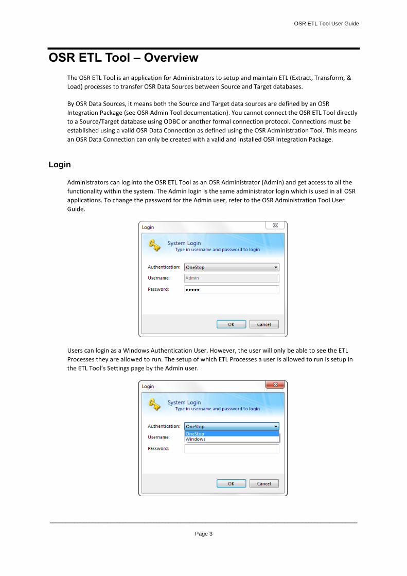
Login
Administrators can log into the OSR ETL Tool as an OSR Administrator (Admin) and get access to all the
functionality within the system. The Admin login is the same administrator login which is used in all OSR
applications. To change the password for the Admin user, refer to the OSR Administration Tool User
Guide.
Users can login as a Windows Authentication User. However, the user will only be able to see the ETL
Processes they are allowed to run. The setup of which ETL Processes a user is allowed to run is setup in
the ETL Tool’s Settings page by the Admin user.
OSR ETL Tool User Guide
_____________________________________________________________________________________________________
Page 4
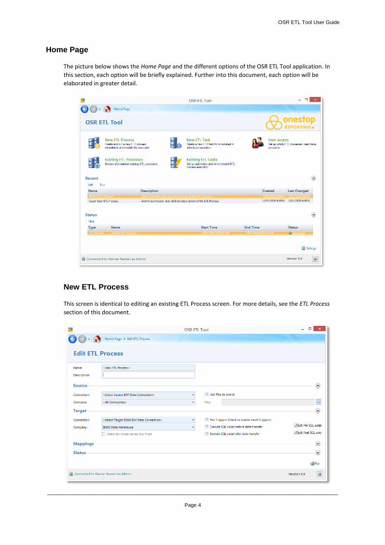
Home Page
The picture below shows the Home Page and the different options of the OSR ETL Tool application. In
this section, each option will be briefly explained. Further into this document, each option will be
elaborated in greater detail.
New ETL Process
This screen is identical to editing an existing ETL Process screen. For more details, see the ETL Process
section of this document.
OSR ETL Tool User Guide
_____________________________________________________________________________________________________
Page 5
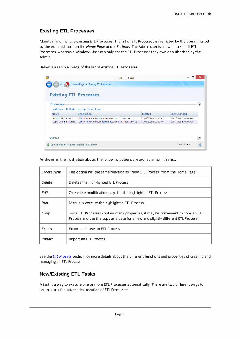
Existing ETL Processes
Maintain and manage existing ETL Processes. The list of ETL Processes is restricted by the user rights set
by the Administrator on the Home Page under Settings. The Admin user is allowed to see all ETL
Processes, whereas a Windows User can only see the ETL Processes they own or authorized by the
Admin.
Below is a sample image of the list of existing ETL Processes:
As shown in the illustration above, the following options are available from this list:
Create New This option has the same function as “New ETL Process” from the Home Page.
Delete Deletes the high-lighted ETL Process
Edit Opens the modification page for the highlighted ETL Process.
Run Manually execute the highlighted ETL Process.
Copy Since ETL Processes contain many properties, it may be convenient to copy an ETL
Process and use the copy as a base for a new and slightly different ETL Process.
Export Export and save an ETL Process
Import Import an ETL Process
See the ETL Process section for more details about the different functions and properties of creating and
managing an ETL Process.
New/Existing ETL Tasks
A task is a way to execute one or more ETL Processes automatically. There are two different ways to
setup a task for automatic execution of ETL Processes:
OSR ETL Tool User Guide
_____________________________________________________________________________________________________
Page 6
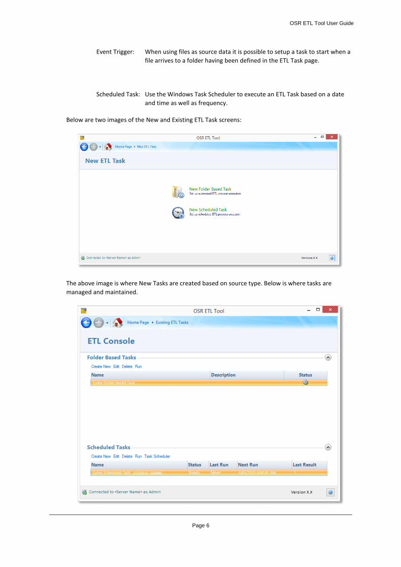
Event Trigger: When using files as source data it is possible to setup a task to start when a
file arrives to a folder having been defined in the ETL Task page.
Scheduled Task: Use the Windows Task Scheduler to execute an ETL Task based on a date
and time as well as frequency.
Below are two images of the New and Existing ETL Task screens:
The above image is where New Tasks are created based on source type. Below is where tasks are
managed and maintained.
OSR ETL Tool User Guide
_____________________________________________________________________________________________________
Page 7
As shown in the ETL Console image, the following options are available:
Create New This option has the same function as “New ETL Task” on the Home Page.
Delete Deletes the high-lighted ETL Task
Edit Opens the modification page for the highlighted ETL Task.
Run Manually start the highlighted ETL Task.
Task
Scheduler Launches Windows Task Scheduler as an alternative to schedule ETL Tasks.
See the Scheduling ETL Task section for more details about the different properties and attributes of
creating and managing an ETL Task.
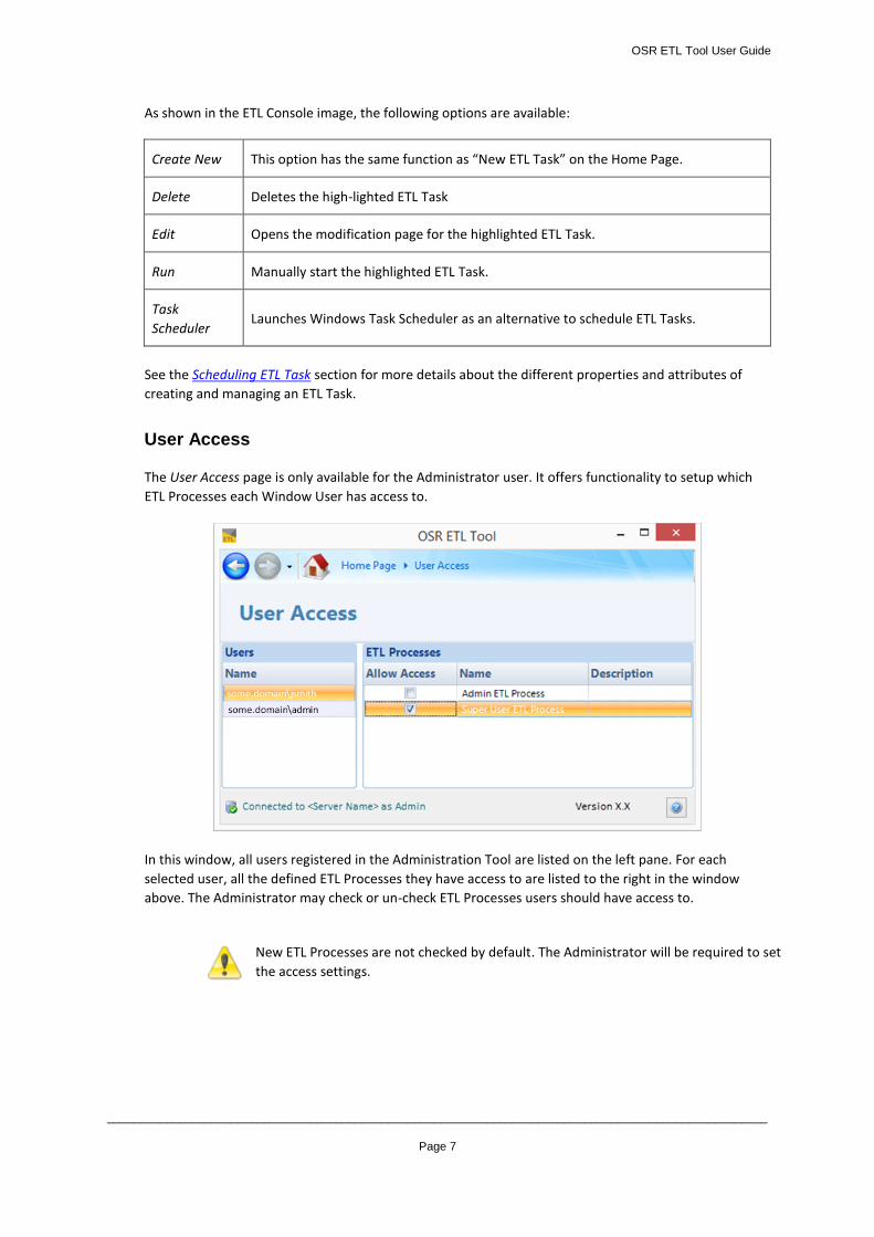
User Access
The User Access page is only available for the Administrator user. It offers functionality to setup which
ETL Processes each Window User has access to.
In this window, all users registered in the Administration Tool are listed on the left pane. For each
selected user, all the defined ETL Processes they have access to are listed to the right in the window
above. The Administrator may check or un-check ETL Processes users should have access to.
New ETL Processes are not checked by default. The Administrator will be required to set
the access settings.
OSR ETL Tool User Guide
_____________________________________________________________________________________________________
Page 8
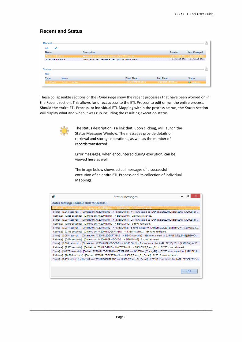
Recent and Status
These collapseable sections of the Home Page show the recent processes that have been worked on in
the Recent section. This allows for direct access to the ETL Process to edit or run the entire process.
Should the entire ETL Process, or individual ETL Mapping within the process be run, the Status section
will display what and when it was run including the resulting execution status.
The status description is a link that, upon clicking, will launch the
Status Messages Window. The messages provide details of
retrieval and storage operations, as well as the number of
records transferred.
Error messages, when encountered during execution, can be
viewed here as well.
The image below shows actual messages of a successful
execution of an entire ETL Process and its collection of individual
Mappings.
OSR ETL Tool User Guide
_____________________________________________________________________________________________________
Page 9
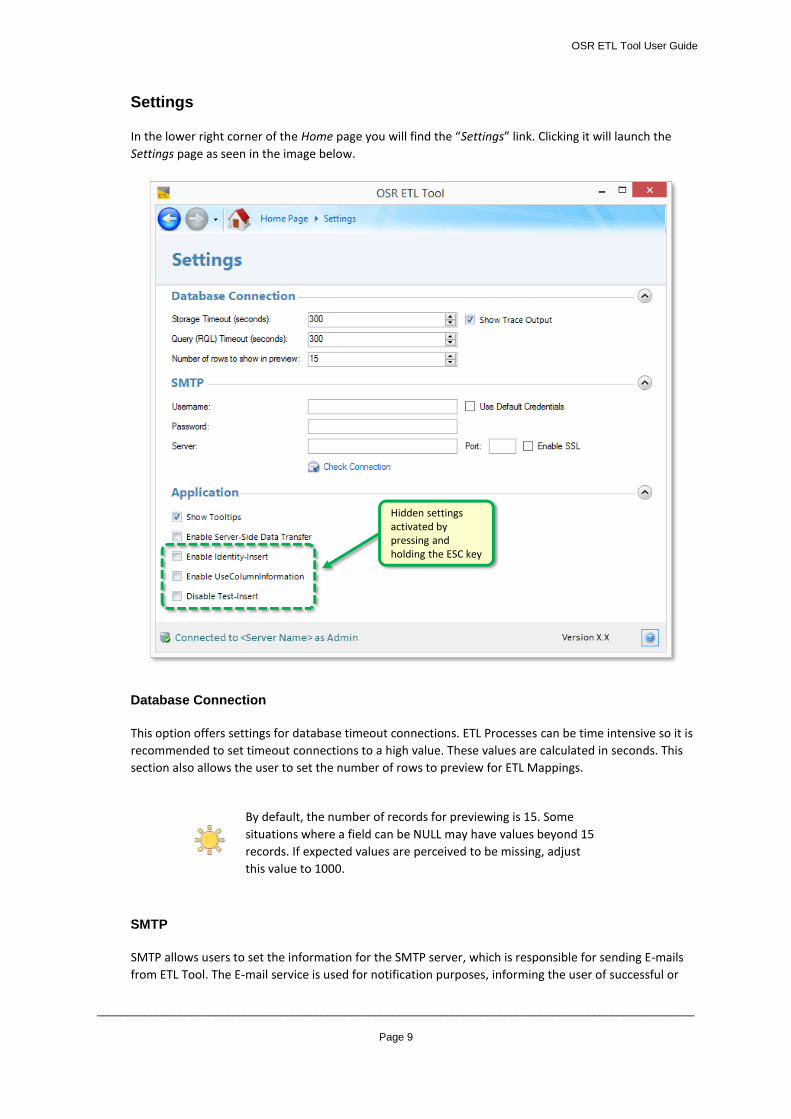
Settings
In the lower right corner of the Home page you will find the “Settings” link. Clicking it will launch the
Settings page as seen in the image below.
Database Connection
This option offers settings for database timeout connections. ETL Processes can be time intensive so it is
recommended to set timeout connections to a high value. These values are calculated in seconds. This
section also allows the user to set the number of rows to preview for ETL Mappings.
By default, the number of records for previewing is 15. Some
situations where a field can be NULL may have values beyond 15
records. If expected values are perceived to be missing, adjust
this value to 1000.
SMTP
SMTP allows users to set the information for the SMTP server, which is responsible for sending E-mails
from ETL Tool. The E-mail service is used for notification purposes, informing the user of successful or
Hidden settings activated by pressing and holding the ESC key
OSR ETL Tool User Guide
_____________________________________________________________________________________________________
Page 10
failed task executions. For additional help configuring the E-mail server setting, contact the
organizational IT Administrator or internet service provider.
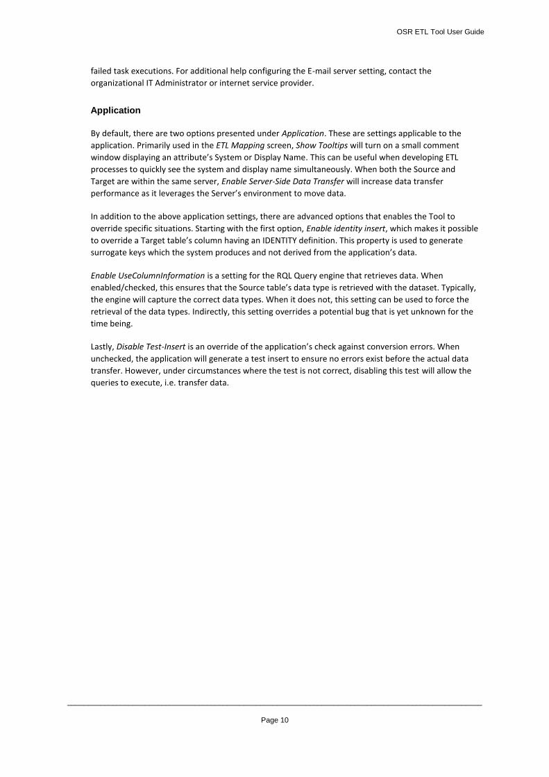
Application
By default, there are two options presented under Application. These are settings applicable to the
application. Primarily used in the ETL Mapping screen, Show Tooltips will turn on a small comment
window displaying an attribute’s System or Display Name. This can be useful when developing ETL
processes to quickly see the system and display name simultaneously. When both the Source and
Target are within the same server, Enable Server-Side Data Transfer will increase data transfer
performance as it leverages the Server’s environment to move data.
In addition to the above application settings, there are advanced options that enables the Tool to
override specific situations. Starting with the first option, Enable identity insert, which makes it possible
to override a Target table’s column having an IDENTITY definition. This property is used to generate
surrogate keys which the system produces and not derived from the application’s data.
Enable UseColumnInformation is a setting for the RQL Query engine that retrieves data. When
enabled/checked, this ensures that the Source table’s data type is retrieved with the dataset. Typically,
the engine will capture the correct data types. When it does not, this setting can be used to force the
retrieval of the data types. Indirectly, this setting overrides a potential bug that is yet unknown for the
time being.
Lastly, Disable Test-Insert is an override of the application’s check against conversion errors. When
unchecked, the application will generate a test insert to ensure no errors exist before the actual data
transfer. However, under circumstances where the test is not correct, disabling this test will allow the
queries to execute, i.e. transfer data.
OSR ETL Tool User Guide
_____________________________________________________________________________________________________
Page 11
Create and Managing ETL Processes
In this section, detailed descriptions of the ETL Tool’s functionality will be explained. In addition, fields
and features of each screen are presented and described in greater length.
In the ETL Tool, an ETL Process is defined as a collection of data Mappings between Source and Target.
The tool allows the User to create multiple ETL Processes to perform different data transfers at various
scheduled times as determined by the User’s requirements. The data transfers are managed through ETL
Mappings. As the word denotes, tables and fields are mapped based on the specified OSR Data
Connection and metadata integration definition. This will be further elaborated in the Creating and
Managing ETL Mappings.
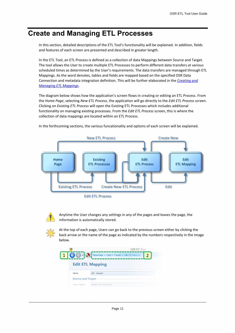
The diagram below shows how the application’s screen flows in creating or editing an ETL Process. From
the Home Page, selecting New ETL Process, the application will go directly to the Edit ETL Process screen.
Clicking on Existing ETL Process will open the Existing ETL Processes which includes additional
functionality on managing existing processes. From the Edit ETL Process screen, this is where the
collection of data mappings are located within an ETL Process.
In the forthcoming sections, the various funcationality and options of each screen will be explained.
Anytime the User changes any settings in any of the pages and leaves the page, the
information is automatically stored.
At the top of each page, Users can go back to the previous screen either by clicking the
back arrow or the name of the page as indicated by the numbers respectively in the image
below.
EditETL Mapping
Create New
Edit
EditETL Process
HomePage
New ETL Process
Existing ETL Process Create New ETL Process
ExistingETL Processes
Edit ETL Process
1 2
OSR ETL Tool User Guide
_____________________________________________________________________________________________________
Page 12
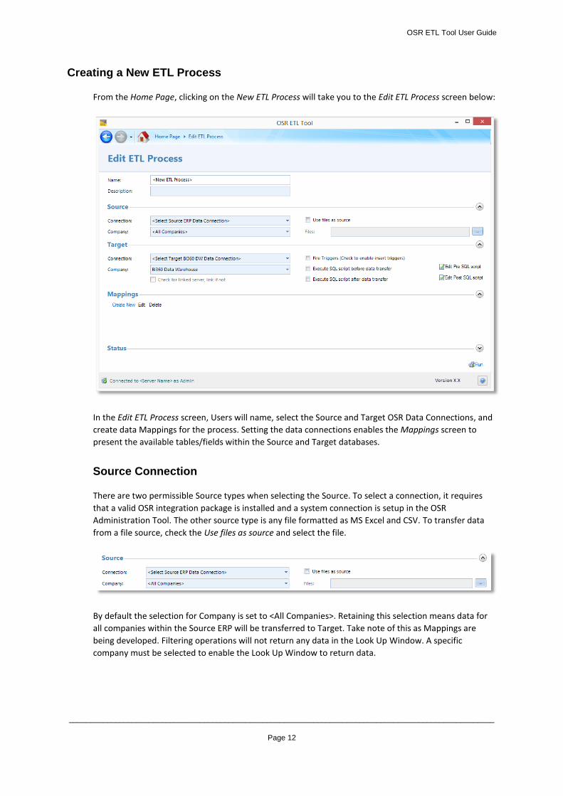
Creating a New ETL Process
From the Home Page, clicking on the New ETL Process will take you to the Edit ETL Process screen below:
In the Edit ETL Process screen, Users will name, select the Source and Target OSR Data Connections, and
create data Mappings for the process. Setting the data connections enables the Mappings screen to
present the available tables/fields within the Source and Target databases.
Source Connection
There are two permissible Source types when selecting the Source. To select a connection, it requires
that a valid OSR integration package is installed and a system connection is setup in the OSR
Administration Tool. The other source type is any file formatted as MS Excel and CSV. To transfer data
from a file source, check the Use files as source and select the file.
By default the selection for Company is set to <All Companies>. Retaining this selection means data for
all companies within the Source ERP will be transferred to Target. Take note of this as Mappings are
being developed. Filtering operations will not return any data in the Look Up Window. A specific
company must be selected to enable the Look Up Window to return data.
OSR ETL Tool User Guide
_____________________________________________________________________________________________________
Page 13
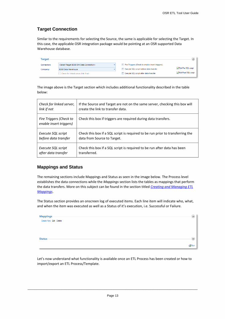
Target Connection
Similar to the requirements for selecting the Source, the same is applicable for selecting the Target. In
this case, the applicable OSR integration package would be pointing at an OSR supported Data
Warehouse database.
The image above is the Target section which includes additional functionality described in the table
below:
Check for linked server,
link if not
If the Source and Target are not on the same server, checking this box will
create the link to transfer data.
Fire Triggers (Check to
enable insert triggers)
Check this box if triggers are required during data transfers.
Execute SQL script
before data transfer
Check this box if a SQL script is required to be run prior to transferring the
data from Source to Target.
Execute SQL script
after data transfer
Check this box if a SQL script is required to be run after data has been
transferred.
Mappings and Status
The remaining sections include Mappings and Status as seen in the image below. The Process level
establishes the data connections while the Mappings section lists the tables as mappings that perform
the data transfers. More on this subject can be found in the section titled Creating and Managing ETL
Mappings.
The Status section provides an onscreen log of executed items. Each line item will indicate who, what,
and when the item was executed as well as a Status of it’s execution, i.e. Successful or Failure.
Let’s now understand what functionality is available once an ETL Process has been created or how to
import/export an ETL Process/Template.
OSR ETL Tool User Guide
_____________________________________________________________________________________________________
Page 14
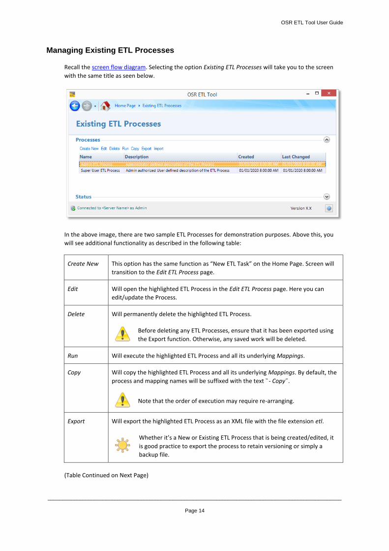
Managing Existing ETL Processes
Recall the screen flow diagram. Selecting the option Existing ETL Processes will take you to the screen
with the same title as seen below.
In the above image, there are two sample ETL Processes for demonstration purposes. Above this, you
will see additional functionality as described in the following table:
Create New This option has the same function as “New ETL Task” on the Home Page. Screen will
transition to the Edit ETL Process page.
Edit Will open the highlighted ETL Process in the Edit ETL Process page. Here you can
edit/update the Process.
Delete Will permanently delete the highlighted ETL Process.
Before deleting any ETL Processes, ensure that it has been exported using
the Export function. Otherwise, any saved work will be deleted.
Run Will execute the highlighted ETL Process and all its underlying Mappings.
Copy Will copy the highlighted ETL Process and all its underlying Mappings. By default, the
process and mapping names will be suffixed with the text ̏- Copy ̋.
Note that the order of execution may require re-arranging.
Export Will export the highlighted ETL Process as an XML file with the file extension etl.
Whether it’s a New or Existing ETL Process that is being created/edited, it
is good practice to export the process to retain versioning or simply a
backup file.
(Table Continued on Next Page)
OSR ETL Tool User Guide
_____________________________________________________________________________________________________
Page 15
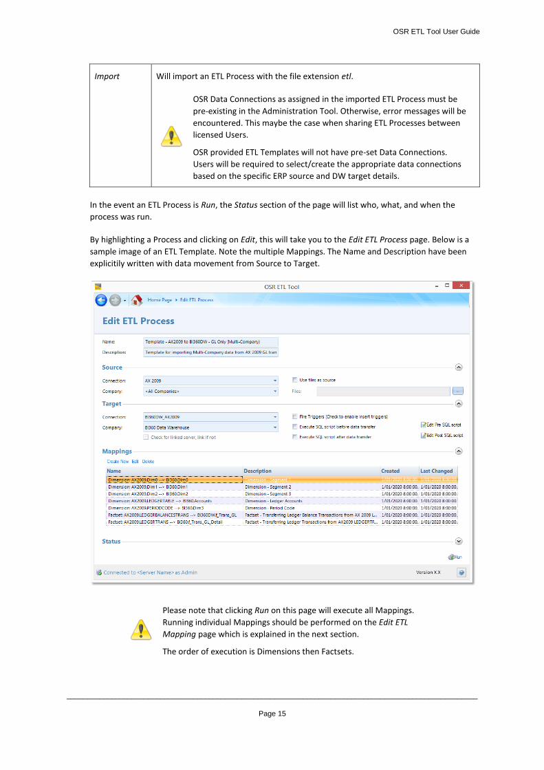
Import Will import an ETL Process with the file extension etl.
OSR Data Connections as assigned in the imported ETL Process must be
pre-existing in the Administration Tool. Otherwise, error messages will be
encountered. This maybe the case when sharing ETL Processes between
licensed Users.
OSR provided ETL Templates will not have pre-set Data Connections.
Users will be required to select/create the appropriate data connections
based on the specific ERP source and DW target details.
In the event an ETL Process is Run, the Status section of the page will list who, what, and when the
process was run.
By highlighting a Process and clicking on Edit, this will take you to the Edit ETL Process page. Below is a
sample image of an ETL Template. Note the multiple Mappings. The Name and Description have been
explicitily written with data movement from Source to Target.
Please note that clicking Run on this page will execute all Mappings.
Running individual Mappings should be performed on the Edit ETL
Mapping page which is explained in the next section.
The order of execution is Dimensions then Factsets.
OSR ETL Tool User Guide
_____________________________________________________________________________________________________
Page 16
Creating and Managing ETL Mappings
Creating a New ETL Mapping
Once an ETL Process has been established, the next step is to create data mappings. These mappings are
the instructions that will transfer data from the Source to Target databases. The specifics of the mapping
will be based on the data connections selected for the given ETL Process. Assignment of the data
mappings are performed in the Edit ETL Mapping page.
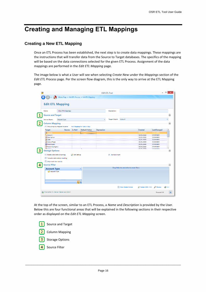
The image below is what a User will see when selecting Create New under the Mappings section of the
Edit ETL Process page. Per the screen flow diagram, this is the only way to arrive at the ETL Mapping
page.
At the top of the screen, similar to an ETL Process, a Name and Description is provided by the User.
Below this are four functional areas that will be explained in the following sections in their respective
order as displayed on the Edit ETL Mapping screen.
Source and Target
Column Mapping
Storage Options
Source Filter
OSR ETL Tool User Guide
_____________________________________________________________________________________________________
Page 17
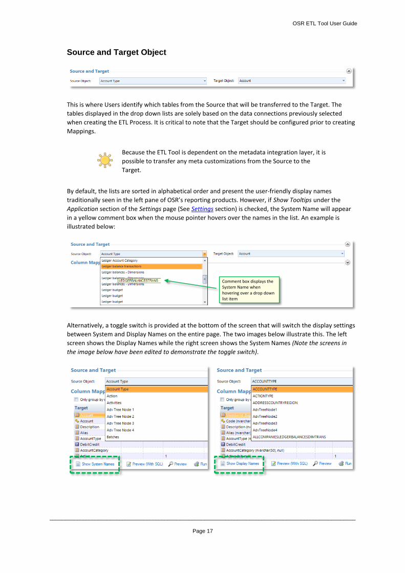
Source and Target Object
This is where Users identify which tables from the Source that will be transferred to the Target. The
tables displayed in the drop down lists are solely based on the data connections previously selected
when creating the ETL Process. It is critical to note that the Target should be configured prior to creating
Mappings.
Because the ETL Tool is dependent on the metadata integration layer, it is
possible to transfer any meta customizations from the Source to the
Target.
By default, the lists are sorted in alphabetical order and present the user-friendly display names
traditionally seen in the left pane of OSR’s reporting products. However, if Show Tooltips under the
Application section of the Settings page (See Settings section) is checked, the System Name will appear
in a yellow comment box when the mouse pointer hovers over the names in the list. An example is
illustrated below:
Alternatively, a toggle switch is provided at the bottom of the screen that will switch the display settings
between System and Display Names on the entire page. The two images below illustrate this. The left
screen shows the Display Names while the right screen shows the System Names (Note the screens in
the image below have been edited to demonstrate the toggle switch).
Comment box displays the System Name when hovering over a drop down list item
OSR ETL Tool User Guide
_____________________________________________________________________________________________________
Page 18
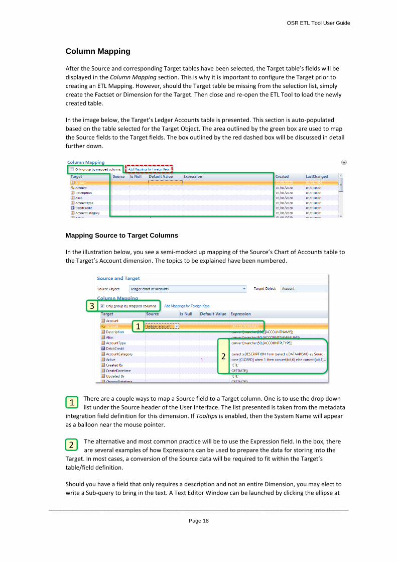
Column Mapping
After the Source and corresponding Target tables have been selected, the Target table’s fields will be
displayed in the Column Mapping section. This is why it is important to configure the Target prior to
creating an ETL Mapping. However, should the Target table be missing from the selection list, simply
create the Factset or Dimension for the Target. Then close and re-open the ETL Tool to load the newly
created table.
In the image below, the Target’s Ledger Accounts table is presented. This section is auto-populated
based on the table selected for the Target Object. The area outlined by the green box are used to map
the Source fields to the Target fields. The box outlined by the red dashed box will be discussed in detail
further down.
Mapping Source to Target Columns
In the illustration below, you see a semi-mocked up mapping of the Source’s Chart of Accounts table to
the Target’s Account dimension. The topics to be explained have been numbered.
There are a couple ways to map a Source field to a Target column. One is to use the drop down
list under the Source header of the User Interface. The list presented is taken from the metadata
integration field definition for this dimension. If Tooltips is enabled, then the System Name will appear
as a balloon near the mouse pointer.
The alternative and most common practice will be to use the Expression field. In the box, there
are several examples of how Expressions can be used to prepare the data for storing into the
Target. In most cases, a conversion of the Source data will be required to fit within the Target’s
table/field definition.
Should you have a field that only requires a description and not an entire Dimension, you may elect to
write a Sub-query to bring in the text. A Text Editor Window can be launched by clicking the ellipse at
1
2
3
1
2
OSR ETL Tool User Guide
_____________________________________________________________________________________________________
Page 19
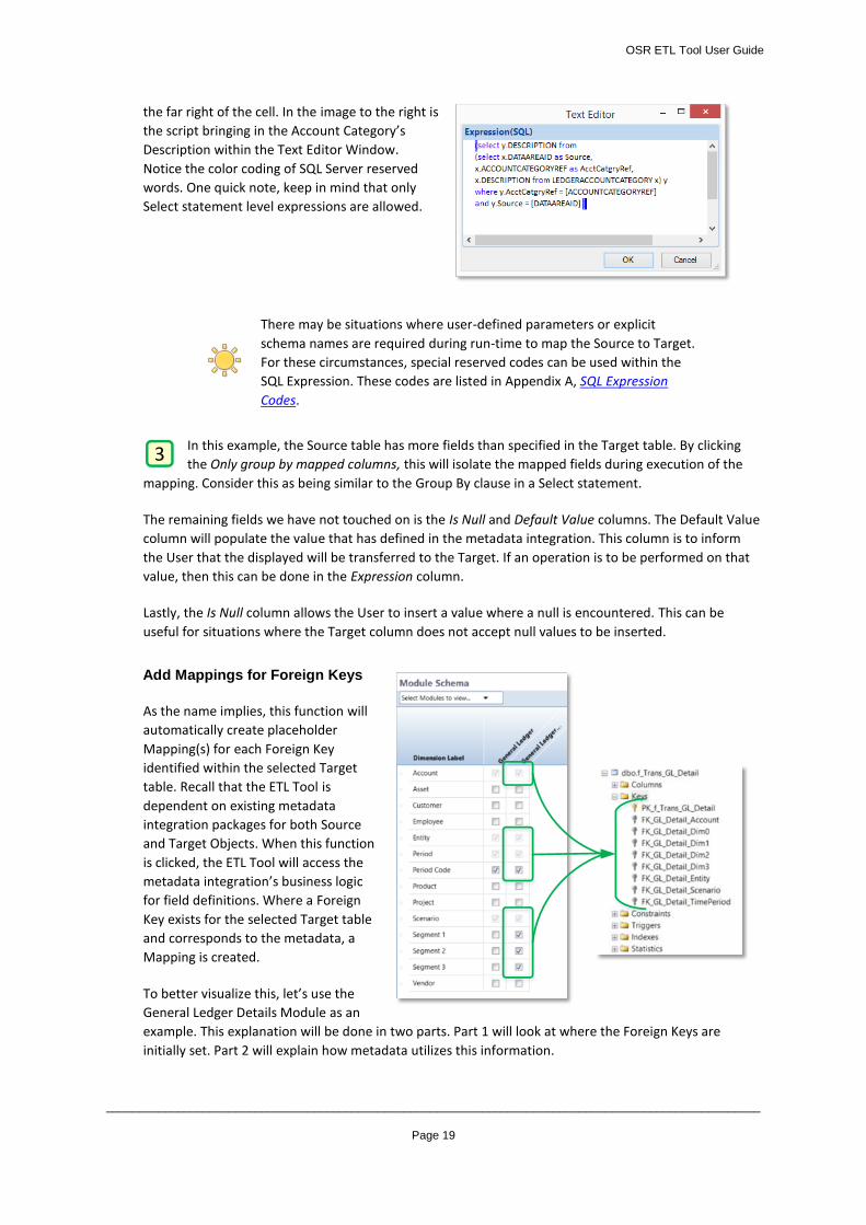
the far right of the cell. In the image to the right is
the script bringing in the Account Category’s
Description within the Text Editor Window.
Notice the color coding of SQL Server reserved
words. One quick note, keep in mind that only
Select statement level expressions are allowed.
There may be situations where user-defined parameters or explicit
schema names are required during run-time to map the Source to Target.
For these circumstances, special reserved codes can be used within the
SQL Expression. These codes are listed in Appendix A, SQL Expression
Codes.
In this example, the Source table has more fields than specified in the Target table. By clicking
the Only group by mapped columns, this will isolate the mapped fields during execution of the
mapping. Consider this as being similar to the Group By clause in a Select statement.
The remaining fields we have not touched on is the Is Null and Default Value columns. The Default Value
column will populate the value that has defined in the metadata integration. This column is to inform
the User that the displayed will be transferred to the Target. If an operation is to be performed on that
value, then this can be done in the Expression column.
Lastly, the Is Null column allows the User to insert a value where a null is encountered. This can be
useful for situations where the Target column does not accept null values to be inserted.
Add Mappings for Foreign Keys
As the name implies, this function will
automatically create placeholder
Mapping(s) for each Foreign Key
identified within the selected Target
table. Recall that the ETL Tool is
dependent on existing metadata
integration packages for both Source
and Target Objects. When this function
is clicked, the ETL Tool will access the
metadata integration’s business logic
for field definitions. Where a Foreign
Key exists for the selected Target table
and corresponds to the metadata, a
Mapping is created.
To better visualize this, let’s use the
General Ledger Details Module as an
example. This explanation will be done in two parts. Part 1 will look at where the Foreign Keys are
initially set. Part 2 will explain how metadata utilizes this information.
3
OSR ETL Tool User Guide
_____________________________________________________________________________________________________
Page 20
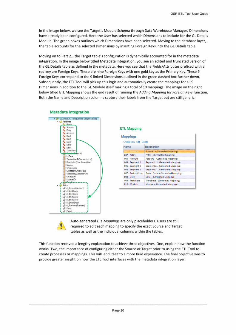
In the image below, we see the Target’s Module Schema through Data Warehouse Manager. Dimensions
have already been configured. Here the User has selected which Dimensions to include for the GL Details
Module. The green boxes outlines which Dimensions have been selected. Moving to the database layer,
the table accounts for the selected Dimensions by inserting Foreign Keys into the GL Details table.
Moving on to Part 2… the Target table’s configuration is dynamically accounted for in the metadata
integration. In the image below titled Metadata Integration, you see an edited and truncated version of
the GL Details table as defined in the metadata. Here you see that the Fields/Attributes prefixed with a
red key are Foreign Keys. There are nine Foreign Keys with one gold key as the Primary Key. These 9
Foreign Keys correspond to the 9 linked Dimensions outlined in the green dashed box further down.
Subsequently, the ETL Tool will pick up this logic and automatically create the mappings for all 9
Dimensions in addition to the GL Module itself making a total of 10 mappings. The image on the right
below titled ETL Mapping shows the end result of running the Adding Mapping for Foreign Keys function.
Both the Name and Description columns capture their labels from the Target but are still generic.
Auto-generated ETL Mappings are only placeholders. Users are still
required to edit each mapping to specify the exact Source and Target
tables as well as the individual columns within the tables.
This function received a lengthy explanation to achieve three objectives. One, explain how the function
works. Two, the importance of configuring either the Source or Target prior to using the ETL Tool to
create processes or mappings. This will lend itself to a more fluid experience. The final objective was to
provide greater insight on how the ETL Tool interfaces with the metadata integration layer.
Metadata Integration
ETL Mapping
OSR ETL Tool User Guide
_____________________________________________________________________________________________________
Page 21
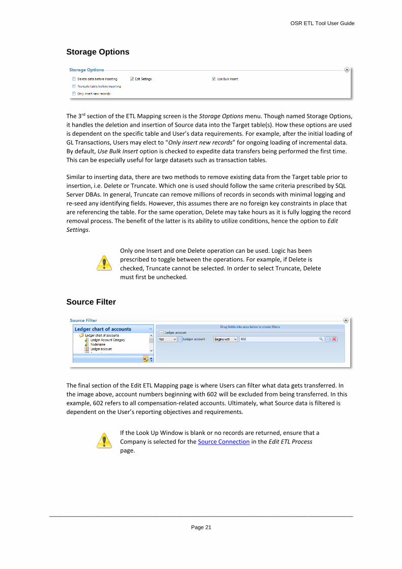
Storage Options
The 3rd section of the ETL Mapping screen is the Storage Options menu. Though named Storage Options,
it handles the deletion and insertion of Source data into the Target table(s). How these options are used
is dependent on the specific table and User’s data requirements. For example, after the initial loading of
GL Transactions, Users may elect to “Only insert new records” for ongoing loading of incremental data.
By default, Use Bulk Insert option is checked to expedite data transfers being performed the first time.
This can be especially useful for large datasets such as transaction tables.
Similar to inserting data, there are two methods to remove existing data from the Target table prior to
insertion, i.e. Delete or Truncate. Which one is used should follow the same criteria prescribed by SQL
Server DBAs. In general, Truncate can remove millions of records in seconds with minimal logging and
re-seed any identifying fields. However, this assumes there are no foreign key constraints in place that
are referencing the table. For the same operation, Delete may take hours as it is fully logging the record
removal process. The benefit of the latter is its ability to utilize conditions, hence the option to Edit
Settings.
Only one Insert and one Delete operation can be used. Logic has been
prescribed to toggle between the operations. For example, if Delete is
checked, Truncate cannot be selected. In order to select Truncate, Delete
must first be unchecked.
Source Filter
The final section of the Edit ETL Mapping page is where Users can filter what data gets transferred. In
the image above, account numbers beginning with 602 will be excluded from being transferred. In this
example, 602 refers to all compensation-related accounts. Ultimately, what Source data is filtered is
dependent on the User’s reporting objectives and requirements.
If the Look Up Window is blank or no records are returned, ensure that a
Company is selected for the Source Connection in the Edit ETL Process
page.
OSR ETL Tool User Guide
_____________________________________________________________________________________________________
Page 22
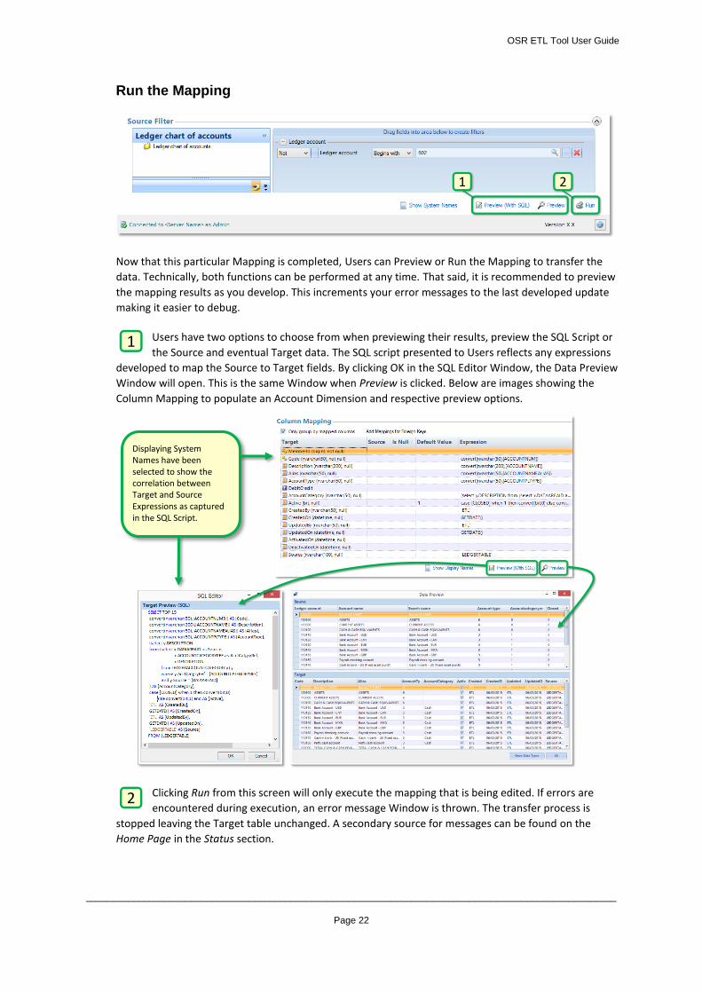
Run the Mapping
Now that this particular Mapping is completed, Users can Preview or Run the Mapping to transfer the
data. Technically, both functions can be performed at any time. That said, it is recommended to preview
the mapping results as you develop. This increments your error messages to the last developed update
making it easier to debug.
Users have two options to choose from when previewing their results, preview the SQL Script or
the Source and eventual Target data. The SQL script presented to Users reflects any expressions
developed to map the Source to Target fields. By clicking OK in the SQL Editor Window, the Data Preview
Window will open. This is the same Window when Preview is clicked. Below are images showing the
Column Mapping to populate an Account Dimension and respective preview options.
Clicking Run from this screen will only execute the mapping that is being edited. If errors are
encountered during execution, an error message Window is thrown. The transfer process is
stopped leaving the Target table unchanged. A secondary source for messages can be found on the
Home Page in the Status section.
1 2
1
Displaying System Names have been selected to show the correlation between Target and Source Expressions as captured in the SQL Script.
2
OSR ETL Tool User Guide
_____________________________________________________________________________________________________
Page 23
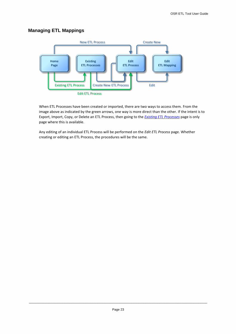
Managing ETL Mappings
When ETL Processes have been created or imported, there are two ways to access them. From the
image above as indicated by the green arrows, one way is more direct than the other. If the intent is to
Export, Import, Copy, or Delete an ETL Process, then going to the Existing ETL Processes page is only
page where this is available.
Any editing of an individual ETL Process will be performed on the Edit ETL Process page. Whether
creating or editing an ETL Process, the procedures will be the same.
Create New
Edit
New ETL Process
Existing ETL Process Create New ETL Process
Edit ETL Process
HomePage
ExistingETL Processes
EditETL Process
EditETL Mapping
OSR ETL Tool User Guide
_____________________________________________________________________________________________________
Page 24
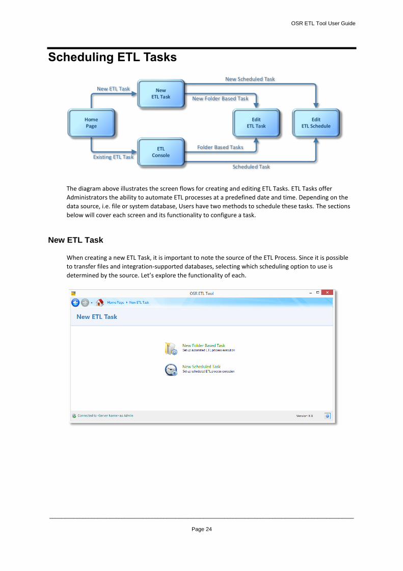
Scheduling ETL Tasks
The diagram above illustrates the screen flows for creating and editing ETL Tasks. ETL Tasks offer
Administrators the ability to automate ETL processes at a predefined date and time. Depending on the
data source, i.e. file or system database, Users have two methods to schedule these tasks. The sections
below will cover each screen and its functionality to configure a task.
New ETL Task
When creating a new ETL Task, it is important to note the source of the ETL Process. Since it is possible
to transfer files and integration-supported databases, selecting which scheduling option to use is
determined by the source. Let’s explore the functionality of each.
New ETL Task
Existing ETL Task
New Folder Based Task
New Scheduled Task
Folder Based Tasks
Scheduled Task
EditETL Task
EditETL Schedule
ETLConsole
HomePage
NewETL Task
OSR ETL Tool User Guide
_____________________________________________________________________________________________________
Page 25
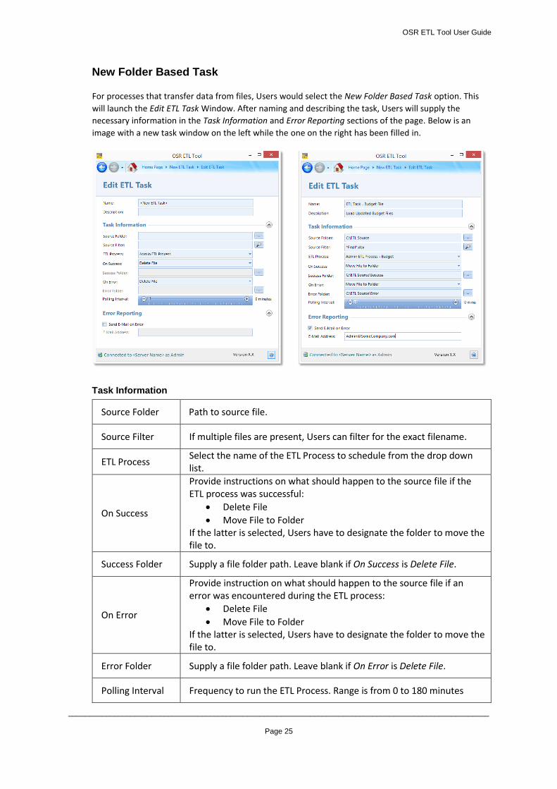
New Folder Based Task
For processes that transfer data from files, Users would select the New Folder Based Task option. This
will launch the Edit ETL Task Window. After naming and describing the task, Users will supply the
necessary information in the Task Information and Error Reporting sections of the page. Below is an
image with a new task window on the left while the one on the right has been filled in.
Task Information
Source Folder Path to source file.
Source Filter If multiple files are present, Users can filter for the exact filename.
ETL Process Select the name of the ETL Process to schedule from the drop down list.
On Success
Provide instructions on what should happen to the source file if the ETL process was successful:
Delete File
Move File to Folder If the latter is selected, Users have to designate the folder to move the file to.
Success Folder Supply a file folder path. Leave blank if On Success is Delete File.
On Error
Provide instruction on what should happen to the source file if an error was encountered during the ETL process:
Delete File
Move File to Folder If the latter is selected, Users have to designate the folder to move the file to.
Error Folder Supply a file folder path. Leave blank if On Error is Delete File.
Polling Interval Frequency to run the ETL Process. Range is from 0 to 180 minutes
OSR ETL Tool User Guide
_____________________________________________________________________________________________________
Page 26
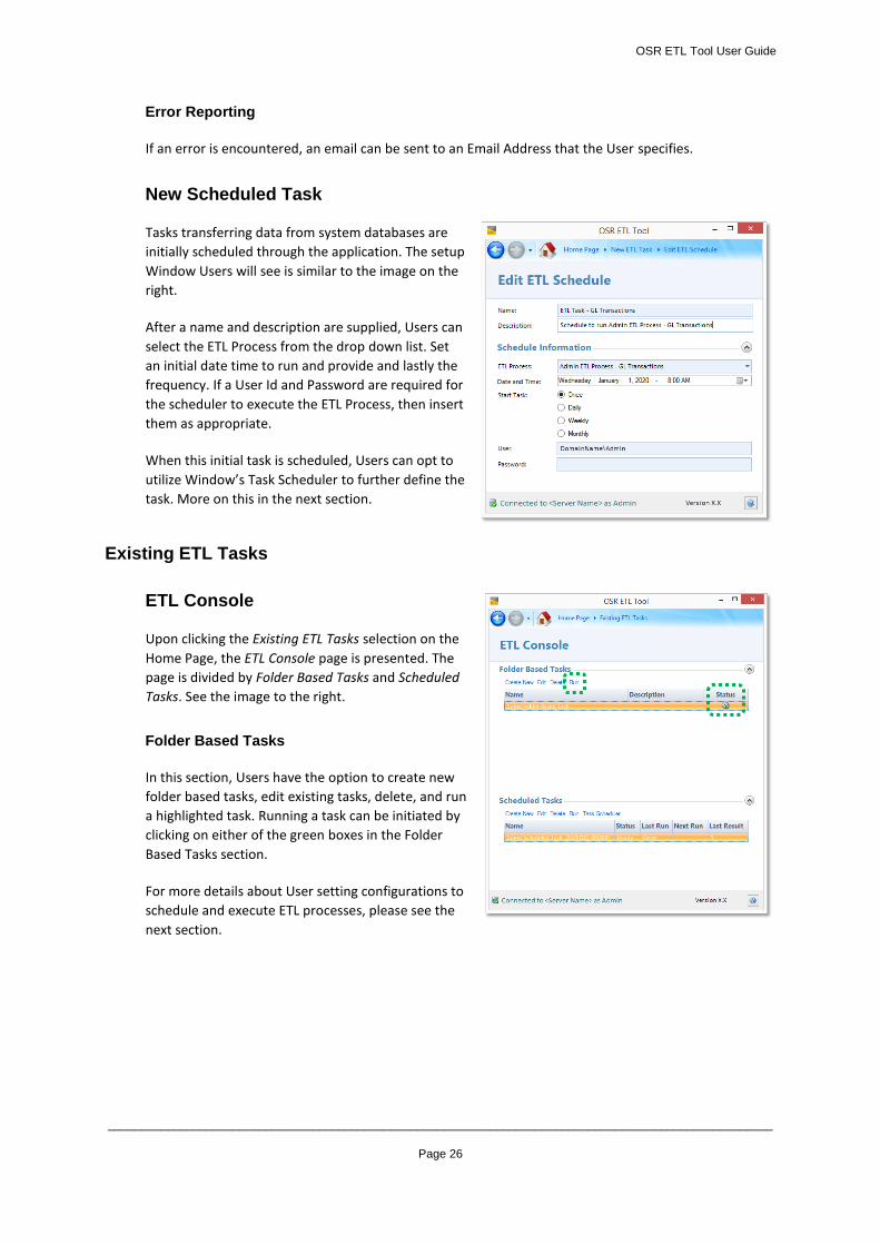
Error Reporting
If an error is encountered, an email can be sent to an Email Address that the User specifies.
New Scheduled Task
Tasks transferring data from system databases are
initially scheduled through the application. The setup
Window Users will see is similar to the image on the
right.
After a name and description are supplied, Users can
select the ETL Process from the drop down list. Set
an initial date time to run and provide and lastly the
frequency. If a User Id and Password are required for
the scheduler to execute the ETL Process, then insert
them as appropriate.
When this initial task is scheduled, Users can opt to
utilize Window’s Task Scheduler to further define the
task. More on this in the next section.
Existing ETL Tasks
ETL Console
Upon clicking the Existing ETL Tasks selection on the
Home Page, the ETL Console page is presented. The
page is divided by Folder Based Tasks and Scheduled
Tasks. See the image to the right.
Folder Based Tasks
In this section, Users have the option to create new
folder based tasks, edit existing tasks, delete, and run
a highlighted task. Running a task can be initiated by
clicking on either of the green boxes in the Folder
Based Tasks section.
For more details about User setting configurations to
schedule and execute ETL processes, please see the
next section.
OSR ETL Tool User Guide
_____________________________________________________________________________________________________
Page 27
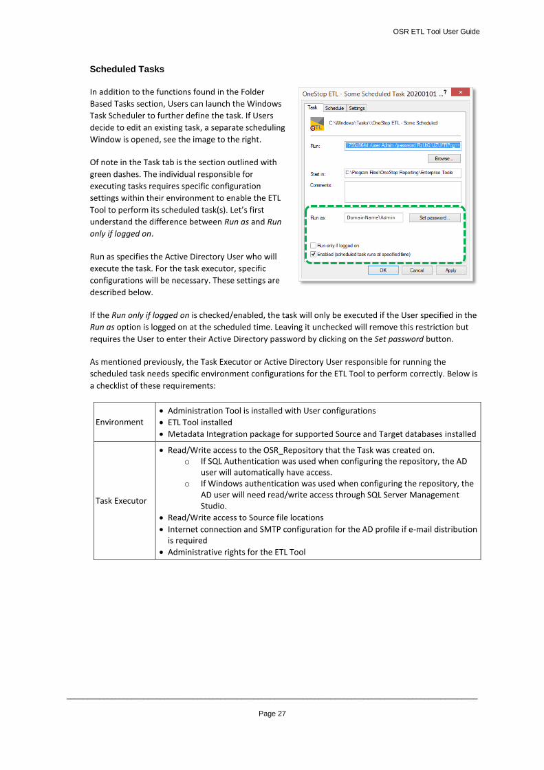
Scheduled Tasks
In addition to the functions found in the Folder
Based Tasks section, Users can launch the Windows
Task Scheduler to further define the task. If Users
decide to edit an existing task, a separate scheduling
Window is opened, see the image to the right.
Of note in the Task tab is the section outlined with
green dashes. The individual responsible for
executing tasks requires specific configuration
settings within their environment to enable the ETL
Tool to perform its scheduled task(s). Let’s first
understand the difference between Run as and Run
only if logged on.
Run as specifies the Active Directory User who will
execute the task. For the task executor, specific
configurations will be necessary. These settings are
described below.
If the Run only if logged on is checked/enabled, the task will only be executed if the User specified in the
Run as option is logged on at the scheduled time. Leaving it unchecked will remove this restriction but
requires the User to enter their Active Directory password by clicking on the Set password button.
As mentioned previously, the Task Executor or Active Directory User responsible for running the
scheduled task needs specific environment configurations for the ETL Tool to perform correctly. Below is
a checklist of these requirements:
Environment Administration Tool is installed with User configurations
ETL Tool installed
Metadata Integration package for supported Source and Target databases installed
Task Executor
Read/Write access to the OSR_Repository that the Task was created on. o If SQL Authentication was used when configuring the repository, the AD
user will automatically have access. o If Windows authentication was used when configuring the repository, the
AD user will need read/write access through SQL Server Management Studio.
Read/Write access to Source file locations
Internet connection and SMTP configuration for the AD profile if e-mail distribution is required
Administrative rights for the ETL Tool
OSR ETL Tool User Guide
_____________________________________________________________________________________________________
Page 28
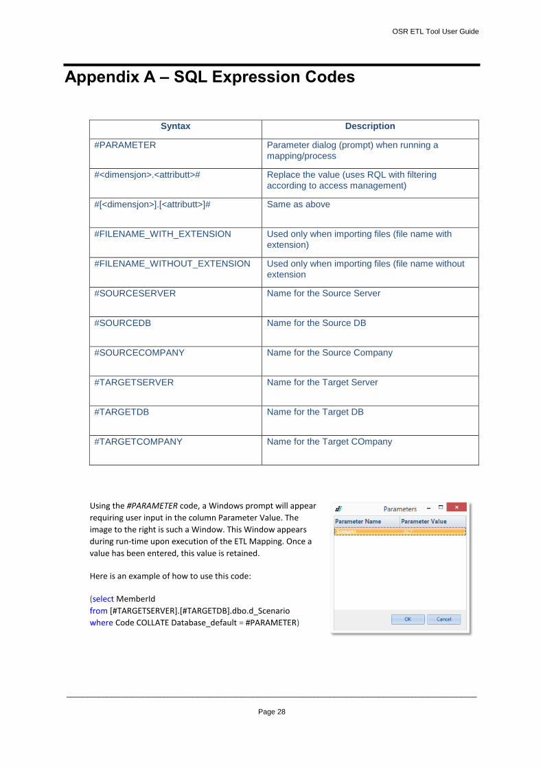
Appendix A – SQL Expression Codes
Syntax Description
#PARAMETER
Parameter dialog (prompt) when running a
mapping/process
#<dimensjon>.<attributt>#
Replace the value (uses RQL with filtering
according to access management)
#[<dimensjon>].[<attributt>]#
Same as above
#FILENAME_WITH_EXTENSION
Used only when importing files (file name with
extension)
#FILENAME_WITHOUT_EXTENSION
Used only when importing files (file name without
extension
#SOURCESERVER
Name for the Source Server
#SOURCEDB
Name for the Source DB
#SOURCECOMPANY
Name for the Source Company
#TARGETSERVER
Name for the Target Server
#TARGETDB
Name for the Target DB
#TARGETCOMPANY
Name for the Target COmpany
Using the #PARAMETER code, a Windows prompt will appear
requiring user input in the column Parameter Value. The
image to the right is such a Window. This Window appears
during run-time upon execution of the ETL Mapping. Once a
value has been entered, this value is retained.
Here is an example of how to use this code:
(select MemberId
from [#TARGETSERVER].[#TARGETDB].dbo.d_Scenario
where Code COLLATE Database_default = #PARAMETER)
OSR ETL Tool User Guide
_____________________________________________________________________________________________________
Page 29
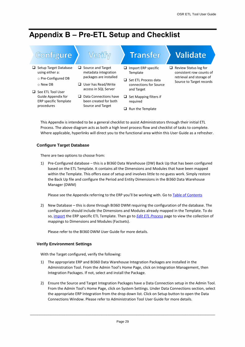
Appendix B – Pre-ETL Setup and Checklist
This Appendix is intended to be a general checklist to assist Administrators through their initial ETL
Process. The above diagram acts as both a high level process flow and checklist of tasks to complete.
Where applicable, hyperlinks will direct you to the functional area within this User Guide as a refresher.
Configure Target Database
There are two options to choose from:
1) Pre-Configured database – this is a BI360 Data Warehouse (DW) Back Up that has been configured
based on the ETL Template. It contains all the Dimensions and Modules that have been mapped
within the Template. This offers ease of setup and involves little to no guess work. Simply restore
the Back Up file and configure the Period and Entity Dimensions in the BI360 Data Warehouse
Manager (DWM)
Please see the Appendix referring to the ERP you’ll be working with. Go to Table of Contents
2) New Database – this is done through BI360 DWM requiring the configuration of the database. The
configuration should include the Dimensions and Modules already mapped in the Template. To do
so, import the ERP specific ETL Template. Then go to Edit ETL Process page to view the collection of
mappings to Dimensions and Modules (Factsets).
Please refer to the BI360 DWM User Guide for more details.
Verify Environment Settings
With the Target configured, verify the following:
1) The appropriate ERP and BI360 Data Warehouse Integration Packages are installed in the
Administration Tool. From the Admin Tool’s Home Page, click on Integration Management, then
Integration Packages. If not, select and install the Package.
2) Ensure the Source and Target Integration Packages have a Data Connection setup in the Admin Tool.
From the Admin Tool’s Home Page, click on System Settings. Under Data Connections section, select
the appropriate ERP Integration from the drop down list. Click on Setup button to open the Data
Connections Window. Please refer to Administration Tool User Guide for more details.
Setup Target Database using either a:
o Pre-Configured DB
o New DB
See ETL Tool User Guide Appendix for ERP specific Template procedures
Source and Target metadata integration packages are installed
User has Read/Write access in SQL Server
Data Connections have been created for both Source and Target
Import ERP specific Template
Set ETL Process data connections for Source and Target
Set Mapping filters if required
Run the Template
Review Status log for consistent row counts of retrieval and storage of Source to Target records
OSR ETL Tool User Guide
_____________________________________________________________________________________________________
Page 30
Verify Environment Settings (cont’d)
3) For Users other than the Administrator, ensure you have Read/Write access in SQL Server to the
Target and at a minimum, Read access to the Source. For further assistance, please contact your IT
Administrator.
Initiate Data Transfer
Now that the Target has been configured and the environment’s conditions have been verified, the ETL
Process can commence.
1) Import the ETL Template for the desired ERP. Open the ETL Tool and from the Home Page, click on
Existing ETL Processes. Click on Import, find the Template with .etl as the file extension.
2) Set the Source and Target Data Connections. From the Existing ETL Processes page, select the
imported Template and click on Edit. Select the Source and Target Data Connections.
3) Select the Company or All Companies for the Source.
4) Set filters on what data to transfer if necessary. This is done within an individual Mapping on the
Edit ETL Mapping page.
5) Run the Template. There are 3 pages in the ETL Tool that will run the entire Template and all its
Mappings. For individual Mappings, they can be executed in the Edit ETL Mappings page.
a. Home Page
b. Existing ETL Processes
c. Edit ETL Process
The order of execution will be all Dimensions first then Modules (Factsets).
Validate Status
When an ETL Process or Mapping is run, a Status Window is opened providing real-time status of what is
happening. Alternatively, the page that Run was clicked has a Status section. It provides a log of activity.
To see the details, click the Status description. This will launch the Status Messages Window.
If an error occurs during the transfer, the ETL Process will terminate. The Target database will not be
written to. In such an event, identify the source of the error and debug the Template. On the contrary, if
no errors are thrown and the Status displays “Successful,” then the process has completed.
Congratulations! You have successfully transferred data from the Source to Target.

OSR ETL Tool User Guide
_____________________________________________________________________________________________________
Page 31
Appendix C – Creating an ETL Template (Under Construction)
OSR ETL Tool User Guide
_____________________________________________________________________________________________________
Page 32
Appendix 1.0 – AX 2009 ETL Template
This Appendix explains the contents of the AX 2009 ETL Template and available resources to have a successful
data transfer.
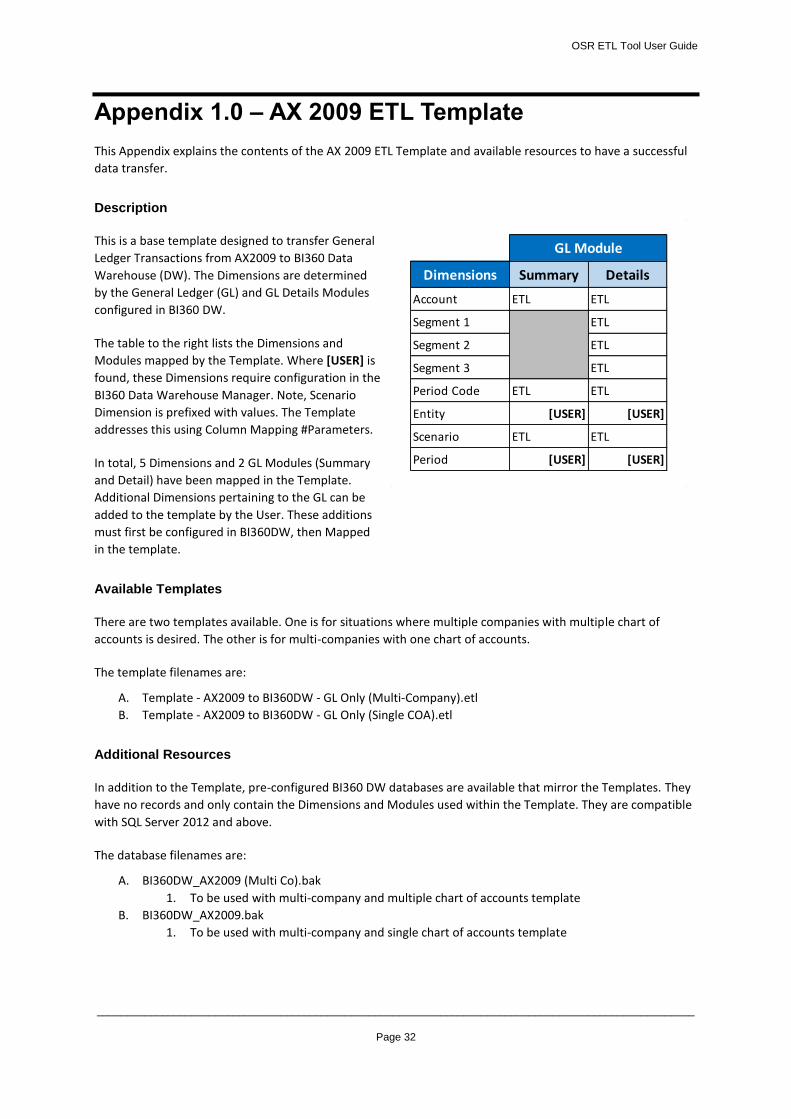
Description
This is a base template designed to transfer General
Ledger Transactions from AX2009 to BI360 Data
Warehouse (DW). The Dimensions are determined
by the General Ledger (GL) and GL Details Modules
configured in BI360 DW.
The table to the right lists the Dimensions and
Modules mapped by the Template. Where [USER] is
found, these Dimensions require configuration in the
BI360 Data Warehouse Manager. Note, Scenario
Dimension is prefixed with values. The Template
addresses this using Column Mapping #Parameters.
In total, 5 Dimensions and 2 GL Modules (Summary
and Detail) have been mapped in the Template.
Additional Dimensions pertaining to the GL can be
added to the template by the User. These additions
must first be configured in BI360DW, then Mapped
in the template.
Available Templates
There are two templates available. One is for situations where multiple companies with multiple chart of
accounts is desired. The other is for multi-companies with one chart of accounts.
The template filenames are:
A. Template - AX2009 to BI360DW - GL Only (Multi-Company).etl
B. Template - AX2009 to BI360DW - GL Only (Single COA).etl
Additional Resources
In addition to the Template, pre-configured BI360 DW databases are available that mirror the Templates. They
have no records and only contain the Dimensions and Modules used within the Template. They are compatible
with SQL Server 2012 and above.
The database filenames are:
A. BI360DW_AX2009 (Multi Co).bak
1. To be used with multi-company and multiple chart of accounts template
B. BI360DW_AX2009.bak
1. To be used with multi-company and single chart of accounts template
Dimensions Summary Details
Account ETL ETL
Segment 1 ETL
Segment 2 ETL
Segment 3 ETL
Period Code ETL ETL
Entity [USER] [USER]
Scenario ETL ETL
Period [USER] [USER]
GL Module