Embed Size (px)
Citation preview
ONE STOP XENON FLASH SOLUTION FOR CAMERAS
CONTENTS
Xenon FLash Lamp (XFL)
Modes of Operation
FlashLampConfigurationandDesignRules
MainDischargeCircuitandTriggerCircuit
GenerationofLightbyXenonDischarge
FlashLampLifeExpectancy
Specifications
Flash Tube Assembly (FTA)
FunctionofReflectorandLens
DesignProcessofFlashTubeAssembly
LightOutputDistribution
IlluminationCoverageAngle
LightOutputMeasurement
Specifications
Integrated Flash Tube Assembly (iFTA)
AdvantagesofiFTA
Xenon Flash Module
ImplementationofXenonFlashinMobilePhoneCamera
•OpticalAssembly
•CapacitorBank
•ElectronicControlCircuit
•SignalInterfacetothePhone
•AutomaticLightControl
•LightOutput
•SignalConnectionConfiguration
•CapacitorConnectionConfiguration
•ElectrostaticControlDischarge
•SafetyandHighVoltageIssuewithXenonCircuit
•MechanicalRobustness
TrimXeFMS-Series
2
2
2
3
6
7
8
11
11
11
12
12
12
13
14
14
14
14
14
14
14
15
15
15
16
16
16
16
16
16
| 01
ApplicationNotes| illuminationsolutions
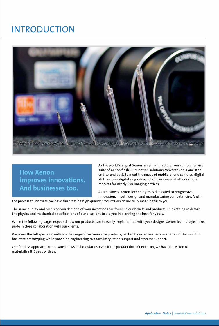
As the world’s largest Xenon lamp manufacturer, our comprehensive suite of Xenon flash illumination solutions converges on a one stop end-to-end basis to meet the needs of mobile phone cameras, digital still cameras, digital single-lens reflex cameras and other camera markets for nearly 600 imaging devices.
As a business, Xenon Technologies is dedicated to progressive innovation, in both design and manufacturing competencies. And in
the process to innovate, we have fun creating high quality products which are truly meaningful to you.
The same quality and precision you demand of your inventions are found in our beliefs and products. This catalogue details the physics and mechanical specifications of our creations to aid you in planning the best for yours.
While the following pages expound how our products can be easily implemented with your designs, Xenon Technologies takes pride in close collaboration with our clients.
We cover the full spectrum with a wide range of customisable products, backed by extensive resources around the world to facilitate prototyping while providing engineering support, integration support and systems support.
Our fearless approach to innovate knows no boundaries. Even if the product doesn’t exist yet, we have the vision to materialise it. Speak with us.
INTRODUCTION
For p x e < 5000, the light efficiency decreases to a great extent. For p x e > 15000, the triggerability may be a problem.
Xenon Flash Lamp
Electronic flash lamps are gas discharge devices for pulse operation and Xenon is often used as a fill-gas for most applications. Krypton is also used for laser excitation. It usually results in flash duration that ranges usually between 10µs and 10 ms.
• Single flash The discharges are produced arbitrarily. This leads to very long off-times in comparison to the flash duration.
• Stroboscopic and beacon operation The discharges are produced periodically over a longer period of time. In most cases, the stroboscopic frequency ranges between 1 Hz and several kHz. Where frequencies are higher, special flash lamps and/or circuitries are required.
• Continuous-wave discharge Electronic flash lamps are unsuited for this mode of operation.
All flash lamps consist of a lamp made of hard or quartz glass with electrodes (anode/cathode) sealed in at each end. The cold cathode contains emitter that reduces the electron work function. In most cases, the discharge does not change its direction of current. Polarity must be carefully observed when connecting flash lamps. Other than linear glass lamps, other shapes, such as U, ring or helix shape are also available. Additionally, non-polarised lamps with two cathodes are also offered. To suit different applications, the glass envelope of flash lamp can be chosen from our wide selection of glass materials.
Almost all flash lamps are equipped with a capacitive trigger electrode. Such as a wire wrapped around the lamp, a silver strip or transparent conductive coating on the outside of the glass.
We also supply leads on electrodes with solid or flexible lead wires based on our standards or your specifications. Some types of lamps are also supplied with bases and protective covers.
Flash lamps are light sources with high power density. Thus, we ensure that they are made of high-temperature materials.
Modes of Operation
Flash Lamp Configuration and Design Rules
XENON FLASH LAMPS (XFL)
02 | 03
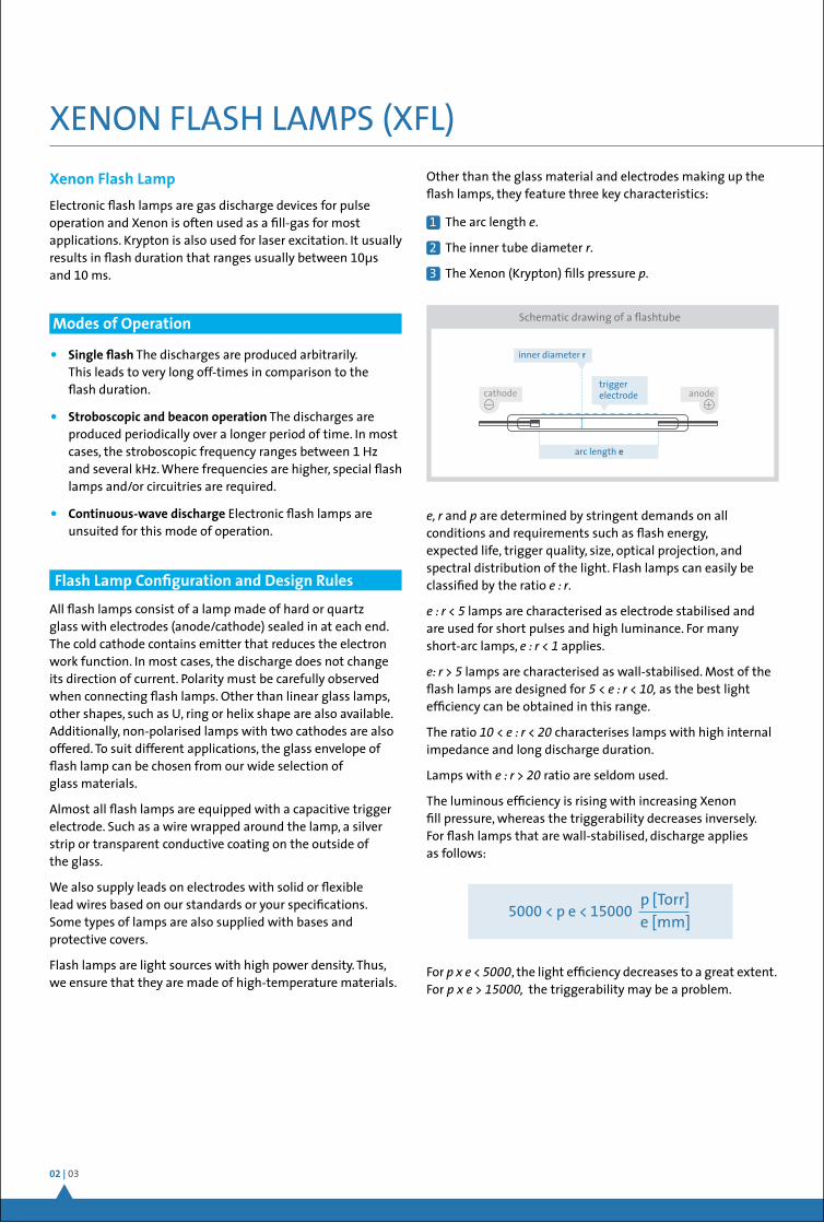
cathode anodetrigger electrode
arc length e
inner diameter r
Schematic drawing of a flashtube
5000 < p e < 15000 p [Torr]e [mm]
e, r and p are determined by stringent demands on all conditions and requirements such as flash energy, expected life, trigger quality, size, optical projection, and spectral distribution of the light. Flash lamps can easily be classified by the ratio e : r.
e : r < 5 lamps are characterised as electrode stabilised and are used for short pulses and high luminance. For many short-arc lamps, e : r < 1 applies.
e: r > 5 lamps are characterised as wall-stabilised. Most of the flash lamps are designed for 5 < e : r < 10, as the best light efficiency can be obtained in this range.
The ratio 10 < e : r < 20 characterises lamps with high internal impedance and long discharge duration.
Lamps with e : r > 20 ratio are seldom used.
The luminous efficiency is rising with increasing Xenon fill pressure, whereas the triggerability decreases inversely. For flash lamps that are wall-stabilised, discharge applies as follows:
1 The arc length e.
2 The inner tube diameter r.
3 The Xenon (Krypton) fills pressure p.
Other than the glass material and electrodes making up the flash lamps, they feature three key characteristics:
ApplicationNotes| illuminationsolutions
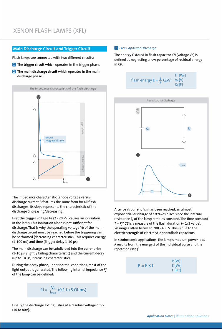
The impedance characteristic (anode voltage versus discharge current i) features the same form for all flash discharges. Its slope represents the characteristic of the discharge (increasing/decreasing).
First the trigger voltage Vz (2 - 20 kV) causes an ionisation in the lamp. This ionisation alone is not sufficient for discharge. That is why the operating voltage Va of the main discharge circuit must be reached before the triggering can be performed (decreasing characteristic). This requires energy (1-100 mJ) and time (Trigger delay 1-10 µs)
The main discharge can be subdivided into the current rise (1-10 µs, slightly failing characteristic) and the current decay (up to 10 µs, increasing characteristic).
During the decay phase, under normal conditions, most of the light output is generated. The following internal impedance Rj of the lamp can be defined:
XENON FLASH LAMPS (XFL)
Ri = (0.1 to 5 Ohms) Vs
imax
P = E x f P [W]E [Ws]f [Hz]
The impedance characteristic of the flash discharge
arrow:Progress of time
V
iimax
VZ
V0
VS
VR
main discharge
trigger phase
Free capacitor discharge
i
t
imax
T
CB Ri
V0
Main Discharge Circuit and Trigger Circuit
Finally, the discharge extinguishes at a residual voltage of VR (10 to 80V).
E [Ws]V0 [V]CB [F]
flash energy E = CBV021
2
1 FreeCapacitorDischarge
The energy E stored in flash capacitor CB (voltage Va) is defined as neglecting a low percentage of residual energy in CB.
After peak current imax has been reached, an almost exponential discharge ofCB takes place since the internal resistance Rjof the lamp remains constant. The time constant T=Rj*CB is a measure of the flash duration (~ 1/3 value). Vo ranges often between 200 - 400 V. This is due to the electric strength of electrolytic photoflash capacitors.
In stroboscopic applications, the lamp’s medium power load P results from the energy E of the individual pulse and the repetition rate f:
Flash lamps are connected with two different circuits:
1 The trigger circuit which operates in the trigger phase.
2 The main discharge circuit which operates in the main discharge phase.
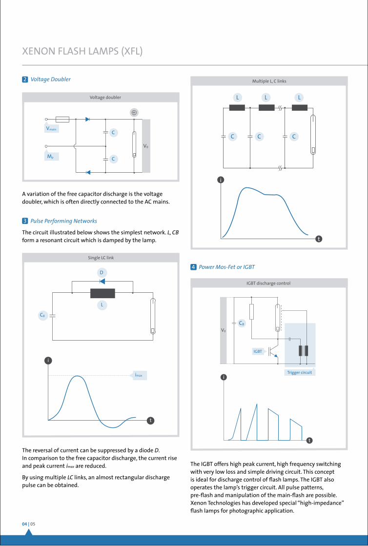
2 VoltageDoubler
A variation of the free capacitor discharge is the voltage doubler, which is often directly connected to the AC mains.
3 PulsePerformingNetworks
The circuit illustrated below shows the simplest network. L,CB form a resonant circuit which is damped by the lamp.
The reversal of current can be suppressed by a diode D. In comparison to the free capacitor discharge, the current rise and peak current imax are reduced.
By using multiple LC links, an almost rectangular discharge pulse can be obtained.
04 | 05
XENON FLASH LAMPS (XFL)
Voltage doubler
Vmain
Mp
V0
C
C
Single LC link
i
t
imax
CB
D
L
4 PowerMos-FetorIGBT
The IGBT offers high peak current, high frequency switching with very low loss and simple driving circuit. This concept is ideal for discharge control of flash lamps. The IGBT also operates the lamp’s trigger circuit. All pulse patterns, pre-flash and manipulation of the main-flash are possible. Xenon Technologies has developed special “high-impedance” flash lamps for photographic application.
i
t
L L
CC C
L
Multiple L, C links
IGBT discharge control
t
i
V0
CB
Trigger circuit
IGBT
ApplicationNotes| illuminationsolutions
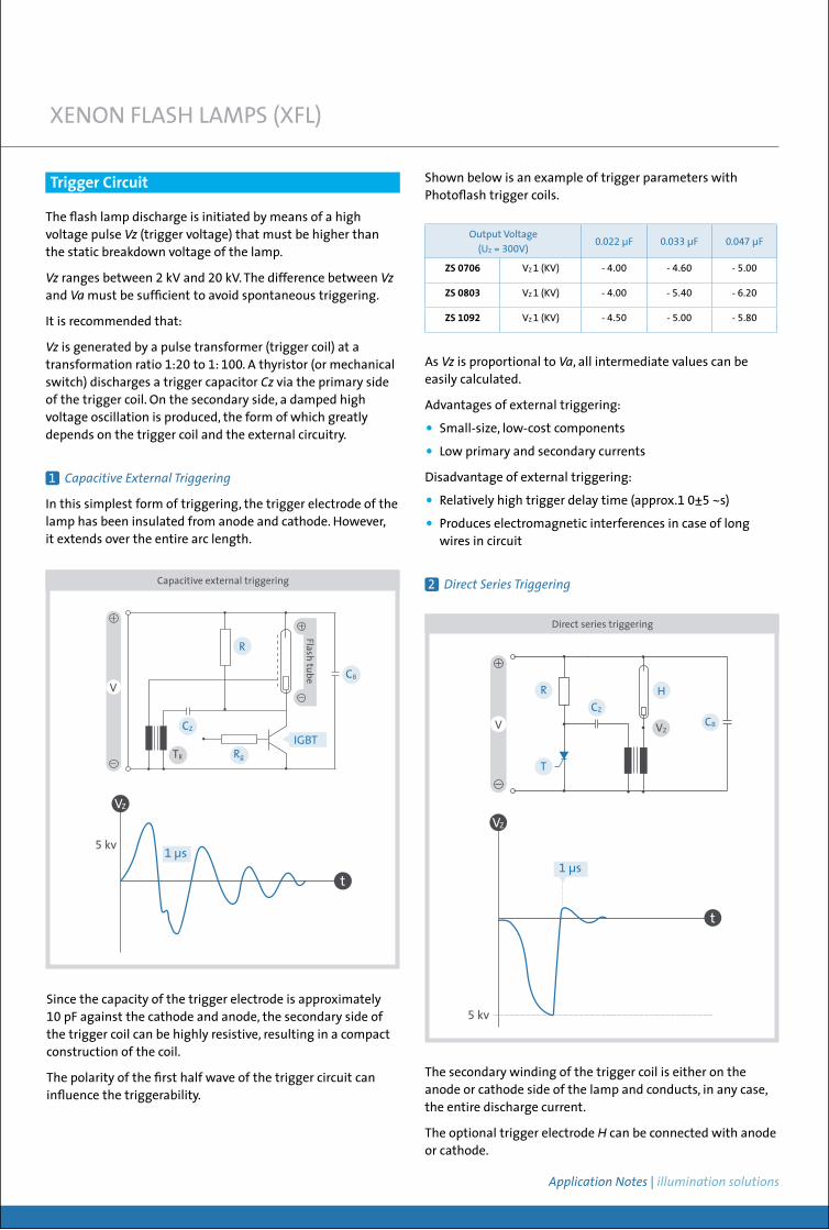
As Vz is proportional to Va, all intermediate values can be easily calculated.
Advantages of external triggering:
• Small-size, low-cost components
• Low primary and secondary currents
Disadvantage of external triggering:
• Relatively high trigger delay time (approx.1 0±5 ~s)
• Produces electromagnetic interferences in case of long wires in circuit
2 DirectSeriesTriggering
XENON FLASH LAMPS (XFL)
Trigger Circuit
The flash lamp discharge is initiated by means of a high voltage pulse Vz (trigger voltage) that must be higher than the static breakdown voltage of the lamp.
Vz ranges between 2 kV and 20 kV. The difference between Vzand Va must be sufficient to avoid spontaneous triggering.
It is recommended that:
Vz is generated by a pulse transformer (trigger coil) at a transformation ratio 1:20 to 1: 100. A thyristor (or mechanical switch) discharges a trigger capacitor Cz via the primary side of the trigger coil. On the secondary side, a damped high voltage oscillation is produced, the form of which greatly depends on the trigger coil and the external circuitry.
1 CapacitiveExternalTriggering
In this simplest form of triggering, the trigger electrode of the lamp has been insulated from anode and cathode. However, it extends over the entire arc length.
IGBT
CB
R
RgTR
CZ
Flash tube
V
Capacitive external triggering
Direct series triggering
Since the capacity of the trigger electrode is approximately 10 pF against the cathode and anode, the secondary side of the trigger coil can be highly resistive, resulting in a compact construction of the coil.
The polarity of the first half wave of the trigger circuit can influence the triggerability.
Output Voltage (UZ = 300V)
0.022 µF 0.033 µF 0.047 µF
ZS 0706 VZ 1 (KV) - 4.00 - 4.60 - 5.00
ZS 0803 VZ 1 (KV) - 4.00 - 5.40 - 6.20
ZS 1092 VZ 1 (KV) - 4.50 - 5.00 - 5.80
5 kv1 µs
t
VZ
The secondary winding of the trigger coil is either on the anode or cathode side of the lamp and conducts, in any case, the entire discharge current.
The optional trigger electrode Hcan be connected with anode or cathode.
CZ
CB
H
V VZ
R
T
1 µs
5 kv
t
VZ
Shown below is an example of trigger parameters with Photoflash trigger coils.
06 | 07
In comparison to the capacitive external triggering, the advantages of direct series triggering are:
• Short trigger delay time (< 1µs) with minimum jitter
• Low emission of electromagnetic interferences
Disadvantages of direct series triggering:
• Large size, high cost components
Xenon Technologies trigger transformers for external triggering are included in this catalogue.
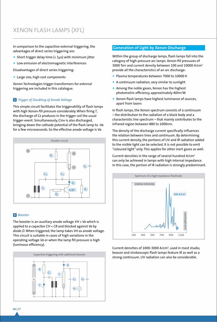
3 TriggerofDoublingofAnodeVoltage
This simple circuit facilitates the triggerability of flash lamps with high Xenon-fill pressure considerably. When firingT, the discharge of Cz produces in the trigger coil the usual trigger-event. Simultaneously, Cinv is also discharged, bringing down the cathode potential of the flash lamp to -Va for a few microseconds. So the effective anode voltage is Va.
Doubler circuit
IGBT
CB
R1
R2
D1
Rg
TR
CZ1 CZ2
4 Booster
The booster is an auxiliary anode voltage VH>Va which is applied to a capacitorCH«CB and blocked againstVa by diode D. When triggered, the lamp takes VH as anode voltage. This circuit is suitable in cases of high variations in the operating voltage Va or when the lamp fill pressure is high (luminous efficiency).
Generation of Light by Xenon Discharge
CZ
Capacitive triggering with additional booster
CB
T
T
DR
CH
VH
V0
Spectrum of a high impedance flashtube
100 300 500 700 900 1100
100 A/cm2
relative intensity
wavelength (nm
)XENON FLASH LAMPS (XFL)
Within the group of discharge lamps, flash lamps fall into the category of high-pressure arc lamps. Xenon fill pressures of 3000 Torr and current density between 100 and 10000 A/cm2 provide all the characteristics of an arc discharge:
• Plasma temperatures between 7000 to 10000 K
• A continuum radiation, very similar to sunlight
• Among the noble gases, Xenon has the highest photometric efficiency, approximately 40lm/W
• Xenon flash lamps have highest luminance of sources, apart from lasers
In flash lamps, the Xenon spectrum consists of a continuum – the distribution to the radiation of a black body and a characteristic line spectrum – that mainly contributes to the infrared region between 880 to 1000nm.
The density of the discharge current specifically influences the relation between lines and continuum. By determining this current density, the portions of UV and IR radiation added to the visible light can be selected. It is not possible to emit “coloured light” only. This applies for other inert gases as well.
Current densities in the range of several hundred A/cm2 can only be achieved in lamps with high internal impedance. In this case, the portion of IR radiation is strongly predominant.
Current densities of 1000-3000 A/cm2, used in most studio, beacon and stroboscopic flash lamps feature IR as well as a strong continuum. UV radiation can also be considerable.
ApplicationNotes| illuminationsolutions
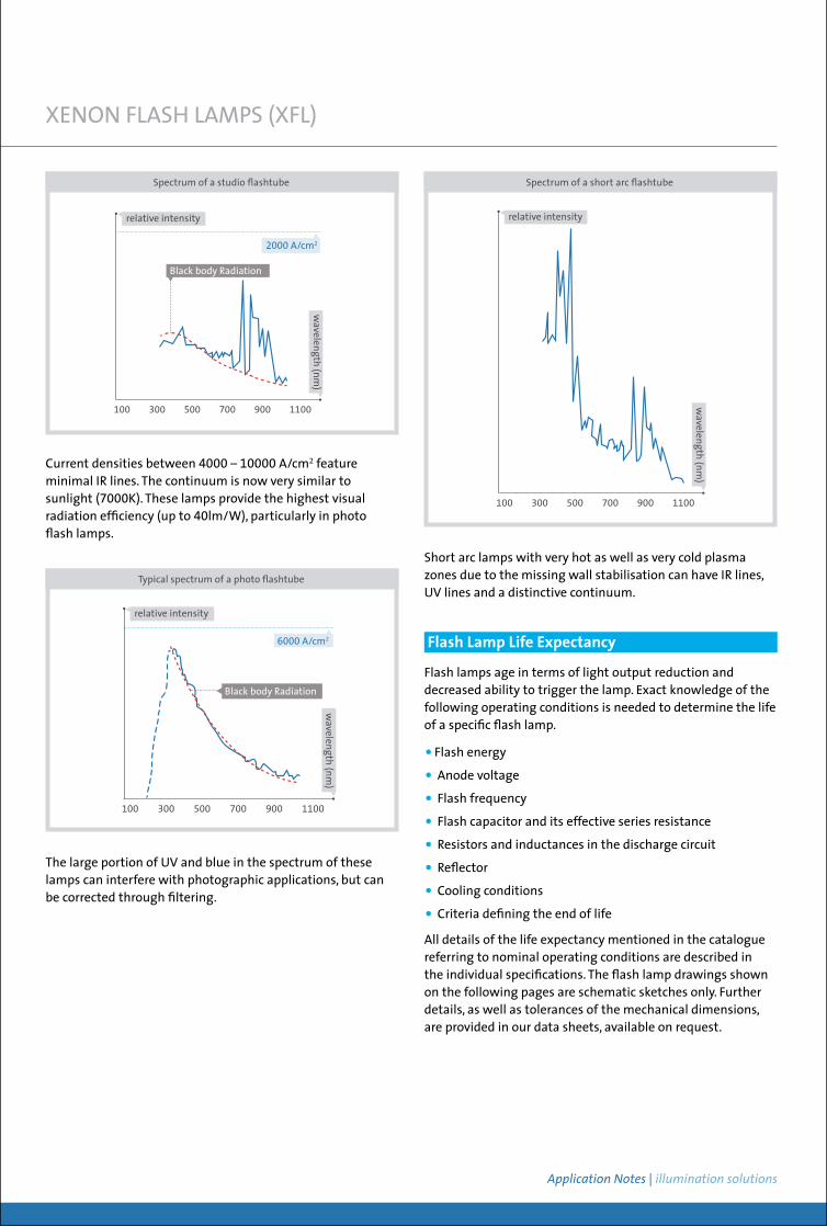
Current densities between 4000 – 10000 A/cm2 feature minimal IR lines. The continuum is now very similar to sunlight (7000K). These lamps provide the highest visual radiation efficiency (up to 40lm/W), particularly in photo flash lamps.
100 300 500 700 900 1100
2000 A/cm2
Black body Radiation
relative intensity
wavelength (nm
)
Spectrum of a studio flashtube
XENON FLASH LAMPS (XFL)
The large portion of UV and blue in the spectrum of these lamps can interfere with photographic applications, but can be corrected through filtering.
100 300 500 700 900 1100
relative intensity
wavelength (nm
)
Spectrum of a short arc flashtube
Typical spectrum of a photo flashtube
100 300 500 700 900 1100
6000 A/cm2
Black body Radiation
relative intensity
wavelength (nm
)
Short arc lamps with very hot as well as very cold plasma zones due to the missing wall stabilisation can have IR lines, UV lines and a distinctive continuum.
Flash lamps age in terms of light output reduction and decreased ability to trigger the lamp. Exact knowledge of the following operating conditions is needed to determine the life of a specific flash lamp.
• Flash energy
• Anode voltage
• Flash frequency
• Flash capacitor and its effective series resistance
• Resistors and inductances in the discharge circuit
• Reflector
• Cooling conditions
• Criteria defining the end of life
All details of the life expectancy mentioned in the catalogue referring to nominal operating conditions are described in the individual specifications. The flash lamp drawings shown on the following pages are schematic sketches only. Further details, as well as tolerances of the mechanical dimensions, are provided in our data sheets, available on request.
Flash Lamp Life Expectancy
08 | 09
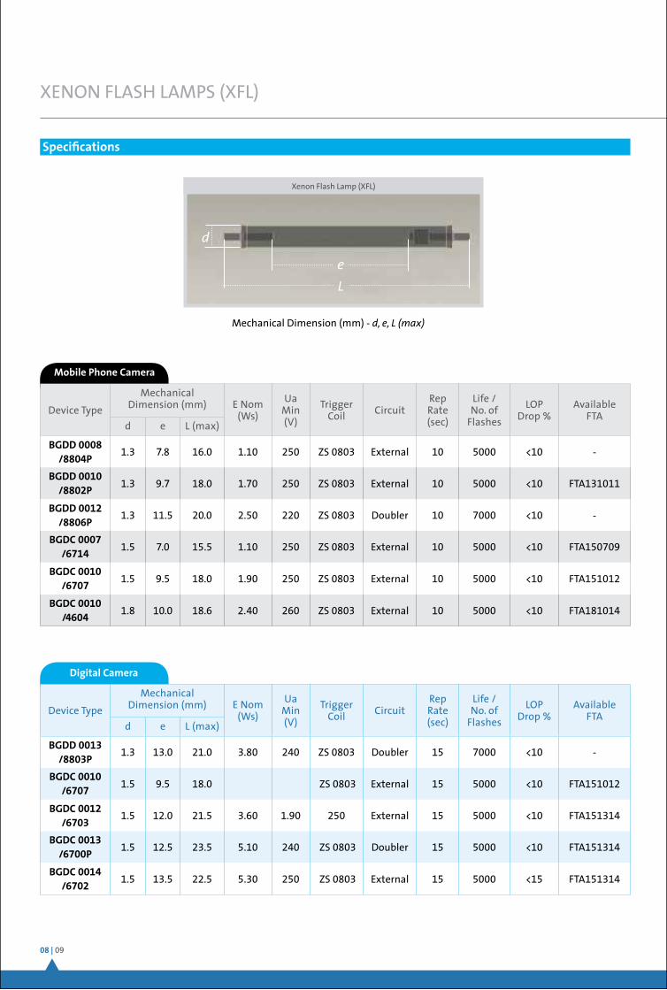
Mobile Phone Camera
Device Type
Mechanical Dimension (mm) E Nom
(Ws)
Ua Min (V)
Trigger Coil Circuit
Rep Rate (sec)
Life / No. of
Flashes
LOP Drop %
Available FTA
d e L (max)
BGDD 0008 /8804P
1.3 7.8 16.0 1.10 250 ZS 0803 External 10 5000 <10 -
BGDD 0010 /8802P
1.3 9.7 18.0 1.70 250 ZS 0803 External 10 5000 <10 FTA131011
BGDD 0012 /8806P
1.3 11.5 20.0 2.50 220 ZS 0803 Doubler 10 7000 <10 -
BGDC 0007 /6714
1.5 7.0 15.5 1.10 250 ZS 0803 External 10 5000 <10 FTA150709
BGDC 0010 /6707
1.5 9.5 18.0 1.90 250 ZS 0803 External 10 5000 <10 FTA151012
BGDC 0010 /4604
1.8 10.0 18.6 2.40 260 ZS 0803 External 10 5000 <10 FTA181014
XENON FLASH LAMPS (XFL)
Specifications
Digital Camera
Device Type
Mechanical Dimension (mm) E Nom
(Ws)
Ua Min (V)
Trigger Coil Circuit
Rep Rate (sec)
Life / No. of
Flashes
LOP Drop %
Available FTA
d e L (max)
BGDD 0013 /8803P
1.3 13.0 21.0 3.80 240 ZS 0803 Doubler 15 7000 <10 -
BGDC 0010 /6707
1.5 9.5 18.0 ZS 0803 External 15 5000 <10 FTA151012
BGDC 0012 /6703
1.5 12.0 21.5 3.60 1.90 250 External 15 5000 <10 FTA151314
BGDC 0013 /6700P
1.5 12.5 23.5 5.10 240 ZS 0803 Doubler 15 5000 <10 FTA151314
BGDC 0014 /6702
1.5 13.5 22.5 5.30 250 ZS 0803 External 15 5000 <15 FTA151314
Xenon Flash Lamp (XFL)
Mechanical Dimension (mm) - d, e, L (max)
d
e
L
ApplicationNotes| illuminationsolutions
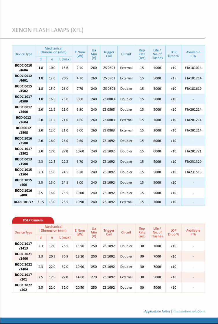
DSLR Camera
Device Type
Mechanical Dimension (mm) E Nom
(Ws)
Ua Min (V)
Trigger Coil Circuit
Rep Rate (sec)
Life / No. of
Flashes
LOP Drop %
Available FTA
d e L (max)
BGDC 1017 /1413
2.3 17.0 26.5 15.90 250 ZS 1092 Doubler 30 7000 <10 -
BGDC 2021 /1400
2.3 20.5 30.5 19.10 250 ZS 1092 Doubler 30 7000 <10 -
BGDC 2022 /1404
2.3 22.0 32.0 19.90 250 ZS 1092 Doubler 30 7000 <10 -
BGDC 1017 /201
2.5 17.5 27.0 14.60 270 ZS 1092 External 30 5000 <10 -
BGDC 2022 /202
2.5 22.0 32.0 20.50 250 ZS 1092 Doubler 30 5000 <10 -
Device Type
Mechanical Dimension (mm) E Nom
(Ws)
Ua Min (V)
Trigger Coil Circuit
Rep Rate (sec)
Life / No. of
Flashes
LOP Drop %
Available FTA
d e L (max)
BGDC 0010 /4604
1.8 10.0 18.6 2.40 260 ZS 0803 External 15 5000 <10 FTA181014
BGDC 0012 /4601
1.8 12.0 20.5 4.30 260 ZS 0803 External 15 5000 <15 FTA181214
BGDC 0015 /4502
1.8 15.0 26.0 7.70 240 ZS 0803 Doubler 15 5000 <10 FTA181619
BGDC 1017 /4500
1.8 16.5 25.0 9.60 240 ZS 0803 Doubler 15 5000 <10 -
BGDC 0012 /2600
2.0 11.5 21.0 5.80 240 ZS 0803 Doubler 15 5000 <10 FTA201214
BGD 0012 /2604
2.0 11.5 21.0 4.80 260 ZS 0803 External 15 3000 <10 FTA201214
BGD 0012 /2508
2.0 12.0 21.0 5.00 260 ZS 0803 External 15 3000 <10 FTA201214
BGDC 1016 /2500
2.0 16.0 26.0 9.60 240 ZS 1092 Doubler 15 6000 <10 -
BGDC 1017 /2502
2.0 17.0 27.0 10.60 240 ZS 1092 Doubler 15 6000 <10 FTA201721
BGDC 0013 /1500
2.3 12.5 22.2 6.70 240 ZS 1092 Doubler 15 5000 <10 FTA231320
BGDC 1015 /1504
2.3 15.0 24.5 8.20 240 ZS 1092 Doubler 15 5000 <10 FTA231518
BGDC 1015 /500
2.5 15.0 24.5 9.00 240 ZS 1092 Doubler 15 5000 <10 -
BGDC 1016 /400
2.5 16.0 25.5 10.00 240 ZS 1092 Doubler 15 5000 <10 -
BGDC 1013 / 3.15 13.0 25.5 10.90 240 ZS 1092 External 15 3000 <10 -
XENON FLASH LAMPS (XFL)
10 | 11
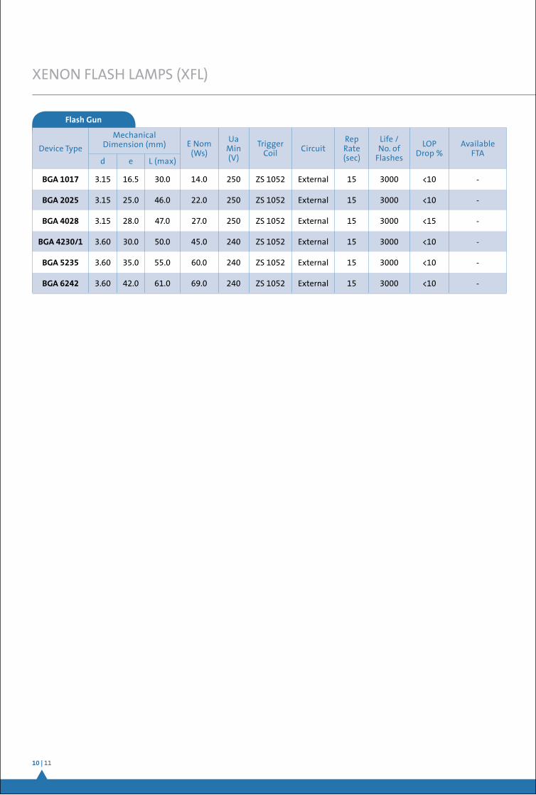
Flash Gun
Device Type
Mechanical Dimension (mm) E Nom
(Ws)
Ua Min (V)
Trigger Coil Circuit
Rep Rate (sec)
Life / No. of
Flashes
LOP Drop %
Available FTA
d e L (max)
BGA 1017 3.15 16.5 30.0 14.0 250 ZS 1052 External 15 3000 <10 -
BGA 2025 3.15 25.0 46.0 22.0 250 ZS 1052 External 15 3000 <10 -
BGA 4028 3.15 28.0 47.0 27.0 250 ZS 1052 External 15 3000 <15 -
BGA 4230/1 3.60 30.0 50.0 45.0 240 ZS 1052 External 15 3000 <10 -
BGA 5235 3.60 35.0 55.0 60.0 240 ZS 1052 External 15 3000 <10 -
BGA 6242 3.60 42.0 61.0 69.0 240 ZS 1052 External 15 3000 <10 -
XENON FLASH LAMPS (XFL)
ApplicationNotes| illuminationsolutions
FLASH TUBE ASSEMBLY (FTA)
Design Process of FTA
Function of Reflector and Lens
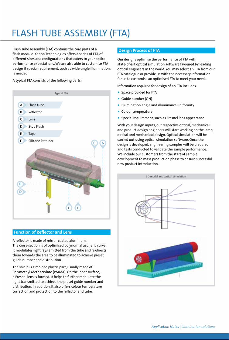
Flash Tube Assembly (FTA) contains the core parts of a flash module. Xenon Technologies offers a series of FTA of different sizes and configurations that caters to your optical performance expectations. We are also able to customise FTA design if special requirement, such as wide-angle illumination, is needed.
A typical FTA consists of the following parts:
Typical FTA
A Flash tube
B Reflector
C Lens
D Stop Flash
E Tape
F Silicone Retainer AC
B
D
E F
A reflector is made of mirror-coated aluminum. The cross-section is of optimised polynomial aspheric curve. It modulates light rays emitted from the tube and re-directs them towards the area to be illuminated to achieve preset guide number and distribution.
The shield is a molded plastic part, usually made of Polymethyl Methacrylate (PMMA). On the inner surface, a Fresnel lens is formed. It helps to further modulate the light transmitted to achieve the preset guide number and distribution. In addition, it also offers colour temperature correction and protection to the reflector and tube.
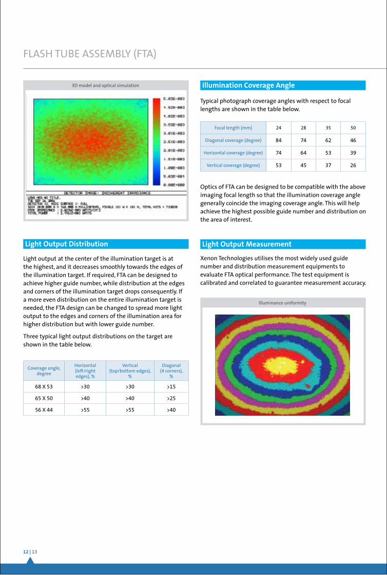
3D model and optical simulation
Our designs optimise the performance of FTA with state-of-art optical simulation software favoured by leading optical engineers in the world. You may select an FTA from our FTA catalogue or provide us with the necessary information for us to customise an optimised FTA to meet your needs.
Information required for design of an FTA includes:
• Space provided for FTA
• Guide number (GN)
• Illumination angle and illuminance uniformity
• Colour temperature
• Special requirement, such as Fresnel lens appearance
With your design inputs, our respective optical, mechanical and product design engineers will start working on the lamp, optical and mechanical design. Optical simulation will be carried out using optical simulation software. Once the design is developed, engineering samples will be prepared and tests conducted to validate the sample performance. We include our customers from the start of sample development to mass production phase to ensure successful new product introduction.
12 | 13
FLASH TUBE ASSEMBLY (FTA)
3D model and optical simulation
Light output at the center of the illumination target is at the highest, and it decreases smoothly towards the edges of the illumination target. If required, FTA can be designed to achieve higher guide number, while distribution at the edges and corners of the illumination target drops consequently. If a more even distribution on the entire illumination target is needed, the FTA design can be changed to spread more light output to the edges and corners of the illumination area for higher distribution but with lower guide number.
Three typical light output distributions on the target are shown in the table below.
Typical photograph coverage angles with respect to focal lengths are shown in the table below.
Light Output Distribution
Illumination Coverage Angle
Coverage angle, degree
Horizontal (left/right edges), %
Vertical (top/bottom edges),
%
Diagonal (4 corners),
%
68 X 53 >30 >30 >15
65 X 50 >40 >40 >25
56 X 44 >55 >55 >40
Focal length (mm) 24 28 35 50
Diagonal coverage (degree) 84 74 62 46
Horizontal coverage (degree) 74 64 53 39
Vertical coverage (degree) 53 45 37 26
Optics of FTA can be designed to be compatible with the above imaging focal length so that the illumination coverage angle generally coincide the imaging coverage angle. This will help achieve the highest possible guide number and distribution on the area of interest.
Xenon Technologies utilises the most widely used guide number and distribution measurement equipments to evaluate FTA optical performance. The test equipment is calibrated and correlated to guarantee measurement accuracy.
Light Output Measurement
Illuminance uniformity
ApplicationNotes| illuminationsolutions
FLASH TUBE ASSEMBLY (FTA)
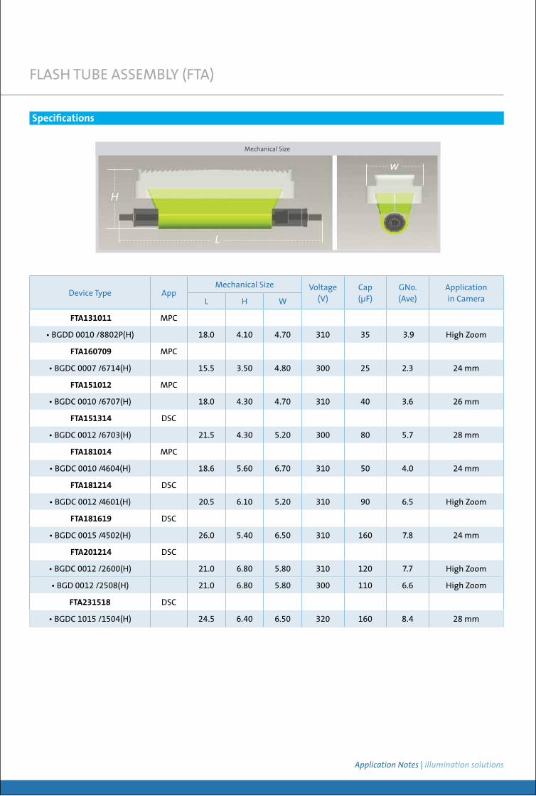
Device Type AppMechanical Size Voltage
(V)Cap(µF)
GNo.(Ave)
Application in Camera L H W
FTA131011 MPC
• BGDD 0010 /8802P(H) 18.0 4.10 4.70 310 35 3.9 High Zoom
FTA160709 MPC
• BGDC 0007 /6714(H) 15.5 3.50 4.80 300 25 2.3 24 mm
FTA151012 MPC
• BGDC 0010 /6707(H) 18.0 4.30 4.70 310 40 3.6 26 mm
FTA151314 DSC
• BGDC 0012 /6703(H) 21.5 4.30 5.20 300 80 5.7 28 mm
FTA181014 MPC
• BGDC 0010 /4604(H) 18.6 5.60 6.70 310 50 4.0 24 mm
FTA181214 DSC
• BGDC 0012 /4601(H) 20.5 6.10 5.20 310 90 6.5 High Zoom
FTA181619 DSC
• BGDC 0015 /4502(H) 26.0 5.40 6.50 310 160 7.8 24 mm
FTA201214 DSC
• BGDC 0012 /2600(H) 21.0 6.80 5.80 310 120 7.7 High Zoom
• BGD 0012 /2508(H) 21.0 6.80 5.80 300 110 6.6 High Zoom
FTA231518 DSC
• BGDC 1015 /1504(H) 24.5 6.40 6.50 320 160 8.4 28 mm
Specifications
Mechanical Size
H
L
w
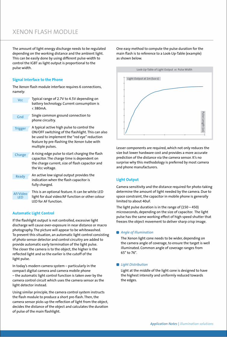
The module is made up of the following working blocks:
Optical Assembly
This is also known as Flashtube Reflector Assembly (FRA). It consists of Xenon flashtube, reflector and Fresnel lens. The flashtube is the line source light output, the reflector redirects all the light energy in a specified direction and the Fresnel lens spread the light uniformly to cover the object plane.
Capacitor Bank
The electrical energy is stored in the flash capacitor for conversion to light energy during the plasma discharge of the Xenon flashtube. The capacitor used is generally smaller (20 – 40 uF) due to space constraint as compared to compact digital camera which is almost twice or more the capacitance.
Electronic Control Circuit
The highly integrated charger IC functions as the dc-dc converter and IGBT driver. The dc-dc converter and the transformer convert the lower battery voltage to ~ 300V to charge up the capacitor. The charging time which depends on charging current can be regulated to suit the total current drawn from the battery. This averts the real time current demand of current close to the ampere range which LED design is based on.
The “trigger circuit” is where a low energy but high electric field takes place when it receives the “Trig” command from the phone that turns ON the IGBT switches. In the presence of the 300V operating voltage and the sudden burst of trigger circuit electrical field, the plasma of high intense discharge of light takes place.
14 | 15
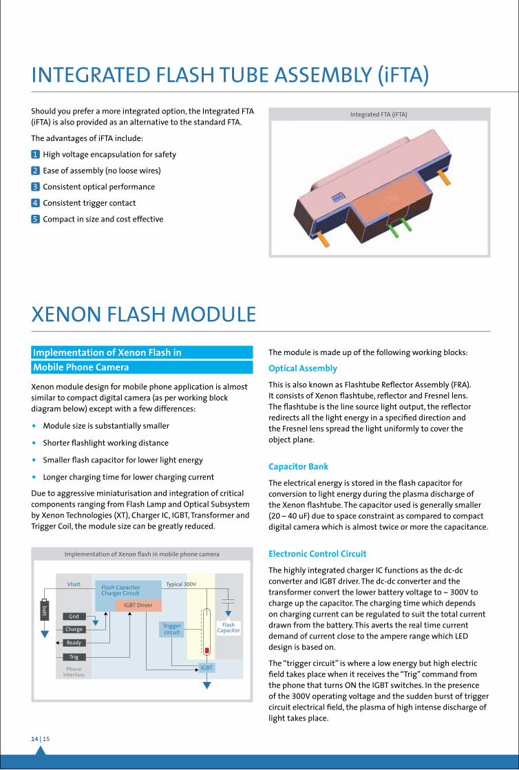
Should you prefer a more integrated option, the Integrated FTA (iFTA) is also provided as an alternative to the standard FTA.
The advantages of iFTA include:
1 High voltage encapsulation for safety
2 Ease of assembly (no loose wires)
3 Consistent optical performance
4 Consistent trigger contact
5 Compact in size and cost effective
Xenon module design for mobile phone application is almost similar to compact digital camera (as per working block diagram below) except with a few differences:
• Module size is substantially smaller
• Shorter flashlight working distance
• Smaller flash capacitor for lower light energy
• Longer charging time for lower charging current
Due to aggressive miniaturisation and integration of critical components ranging from Flash Lamp and Optical Subsystem by Xenon Technologies (XT), Charger IC, IGBT, Transformer and Trigger Coil, the module size can be greatly reduced.
INTEGRATED FLASH TUBE ASSEMBLY (iFTA)
Integrated FTA (iFTA)
XENON FLASH MODULE
Implementation of Xenon Flash in Mobile Phone Camera
Implementation of Xenon flash in mobile phone camera
Flash Capacitor
Trigger circuit
IGBT
Flash Capacitor Charger Circuit
IGBT Driver
Typical 300VVbatt
Phone Interface
Gnd
Ready
Charge
Trig
batt
ApplicationNotes| illuminationsolutions
Light Output
Camera sensitivity and the distance required for photo-taking determine the amount of light needed by the camera. Due to space constraint, the capacitor in mobile phone is generally limited to about 40uF.
The light pulse duration is in the range of (150 – 450) microseconds, depending on the size of capacitor. The light pulse has the same working effect of high speed shutter that freezes the object movement to deliver sharp crisp image.
AngleofIllumination
The Xenon light cone needs to be wider, depending on the camera angle of coverage, to ensure the target is well illuminated. Common angle of coverage ranges from 65° to 76°.
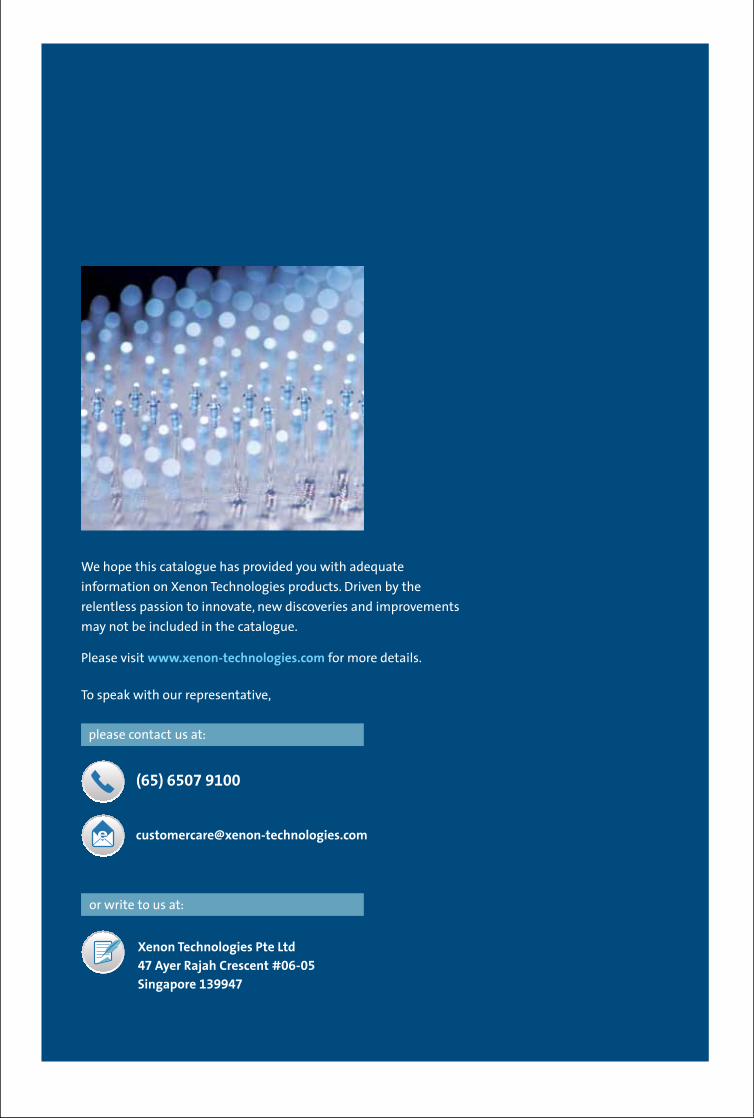
LightDistribution
Light at the middle of the light cone is designed to have the highest intensity and uniformly reduced towards the edges.
XENON FLASH MODULE
The amount of light energy discharge needs to be regulated depending on the working distance and the ambient light. This can be easily done by using different pulse-width to control the IGBT as light output is proportional to the pulse width.
Signal Interface to the Phone
The Xenon flash module interface requires 6 connections, namely:
Typical range of 2.7V to 4.5V depending on battery technology. Current consumption is < 380mA.
Single common ground connection to phone circuitry.
A typical active high pulse to control the ON/OFF switching of the flashlight. This can also be used to implement the “red eye” reduction feature by pre-flashing the Xenon tube with multiple pulses.
A rising edge pulse to start charging the flash capacitor. The charge time is dependent on the charge current, size of flash capacitor and the Vcc voltage.
An active low signal output provides the indication when the flash capacitor is fully charged.
This is an optional feature. It can be white LED light for dual video/AF function or other colour LED for AF function.
Automatic Light Control
If the flashlight output is not controlled, excessive light discharge will cause over-exposure in near distance or macro photography. The picture will appear to be whitewashed. To prevent this situation, an automatic light control consisting of photo sensor detector and control circuitry are added to provide automatic early termination of the light pulse. The closer the camera is to the object, the higher is the reflected light and so the earlier is the cutoff of the light pulse.
In today’s modern camera system – particularly in the compact digital camera and camera mobile phone – the automatic light control function is taken over by the camera control circuit which uses the camera sensor as the light detector instead.
Using similar principle, the camera control system instructs the flash module to produce a short pre-flash. Then, the camera sensor picks up the reflection of light from the object, decides the distance of the object and calculates the duration of pulse of the main flashlight.
Vcc
Gnd
Trigger
Charge
Ready
AF/VideoLED
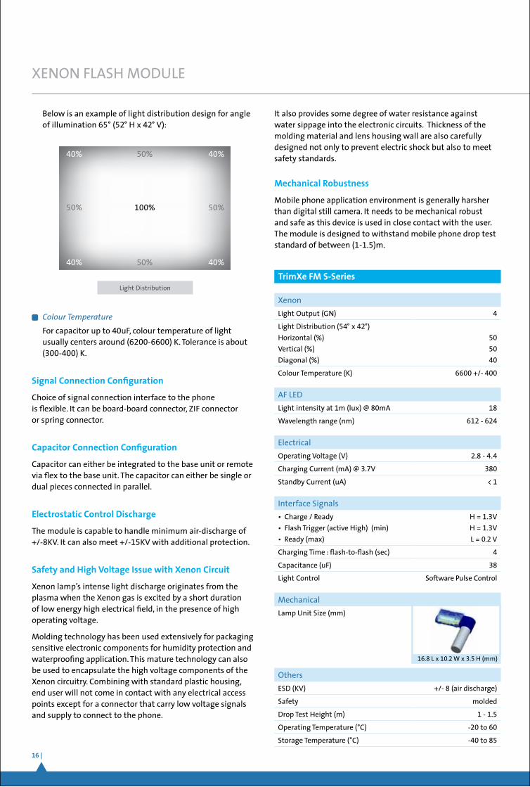
Lesser components are required, which not only reduces the size but lower hardware cost and provides a more accurate prediction of the distance via the camera sensor. It’s no surprise why this methodology is preferred by most camera and phone manufacturers.
Look-Up-Table of Light Output vs Pulse Width
Light Output at 1m (lux-s)
Pulse Length (us)
One easy method to compute the pulse duration for the main flash is to reference to a Look-Up-Table (example) as shown below.
16 |
XENON FLASH MODULE
ColourTemperature
For capacitor up to 40uF, colour temperature of light usually centers around (6200-6600) K. Tolerance is about (300-400) K.
Signal Connection Configuration
Choice of signal connection interface to the phone is flexible. It can be board-board connector, ZIF connector or spring connector.
Capacitor Connection Configuration
Capacitor can either be integrated to the base unit or remote via flex to the base unit. The capacitor can either be single or dual pieces connected in parallel.
Electrostatic Control Discharge
The module is capable to handle minimum air-discharge of +/-8KV. It can also meet +/-15KV with additional protection.
Safety and High Voltage Issue with Xenon Circuit
Xenon lamp’s intense light discharge originates from the plasma when the Xenon gas is excited by a short duration of low energy high electrical field, in the presence of high operating voltage.
Molding technology has been used extensively for packaging sensitive electronic components for humidity protection and waterproofing application. This mature technology can also be used to encapsulate the high voltage components of the Xenon circuitry. Combining with standard plastic housing, end user will not come in contact with any electrical access points except for a connector that carry low voltage signals and supply to connect to the phone.
It also provides some degree of water resistance against water sippage into the electronic circuits. Thickness of the molding material and lens housing wall are also carefully designed not only to prevent electric shock but also to meet safety standards.
Mechanical Robustness
Mobile phone application environment is generally harsher than digital still camera. It needs to be mechanical robust and safe as this device is used in close contact with the user. The module is designed to withstand mobile phone drop test standard of between (1-1.5)m.
50%
50%
100%
40% 40%
40% 40%
50% 50%
Light Distribution
Xenon
Light Output (GN) 4
Light Distribution (54° x 42°)
Horizontal (%)
Vertical (%)
Diagonal (%)
50
50
40
Colour Temperature (K) 6600 +/- 400
AF LED
Light intensity at 1m (lux) @ 80mA 18
Wavelength range (nm) 612 - 624
Electrical
Operating Voltage (V) 2.8 - 4.4
Charging Current (mA) @ 3.7V 380
Standby Current (uA) < 1
Interface Signals
• Charge / Ready
• Flash Trigger (active High) (min)
• Ready (max)
H = 1.3V
H = 1.3V
L = 0.2 V
Charging Time : flash-to-flash (sec) 4
Capacitance (uF) 38
Light Control Software Pulse Control
Mechanical
Lamp Unit Size (mm)
Others
ESD (KV) +/- 8 (air discharge)
Safety molded
Drop Test Height (m) 1 - 1.5
Operating Temperature (°C) -20 to 60
Storage Temperature (°C) -40 to 85
16.8 L x 10.2 W x 3.5 H (mm)
TrimXe FM S-Series
Below is an example of light distribution design for angle of illumination 65° (52° H x 42° V):
We hope this catalogue has provided you with adequate
information on Xenon Technologies products. Driven by the
relentless passion to innovate, new discoveries and improvements
may not be included in the catalogue.
Please visit www.xenon-technologies.com for more details.
To speak with our representative,
(65) 6507 9100
Xenon Technologies Pte Ltd47 Ayer Rajah Crescent #06-05 Singapore 139947
or write to us at:
please contact us at:
Copy Rights © Xenon Technologies Pte Ltd
47 Ayer Rajah Crescent #06-05, Singapore 139947
www.xenon-technologies.com
Business Registration No. 200923745D


![[New Symmetry Issue] Xenon, Xenon Everywhere; A Measurement to Watch](https://img.pdfslide.us/doc/110x75/563db844550346aa9a9221ed/new-symmetry-issue-xenon-xenon-everywhere-a-measurement-to-watch.jpg)