Embed Size (px)
Citation preview
8/6/2019 One Night I Walked Home Very Late and Fell Asleep in Somebody
http://slidepdf.com/reader/full/one-night-i-walked-home-very-late-and-fell-asleep-in-somebody 1/34
"One night I walked home very late and fell asleep in
somebody's satellite dish. My dreams were showing up on TVs
all over the world."
-- Steven Wright
Basic Principles
Up until now, we've been discussing the principles of how to produce televisionsound and pictures. All of this is of little use if we have no way of actually sending thisprogram material to our viewers. This section will deal with the challenge of aimingour telecasts to the public at large.
Radio
We transmit our television programs using radio frequency (RF) waves. A look athow radio itself is sent will provide us with a solid background with which to studytelevision broadcasting.
Radio relies on the radiation of energy from a transmitting antenna in the formof radio waves. These radio waves, travelling at the speed of light (300,000km/sec, or 186,000 miles/sec), carry the information. When the waves arrive at a
receiving antenna, a small electrical voltage is produced. After this voltage has beensuitably amplified, the original information contained in the radio waves is retrievedand presented in an understandable form from a loudspeaker.
Transmission
8/6/2019 One Night I Walked Home Very Late and Fell Asleep in Somebody
http://slidepdf.com/reader/full/one-night-i-walked-home-very-late-and-fell-asleep-in-somebody 2/34
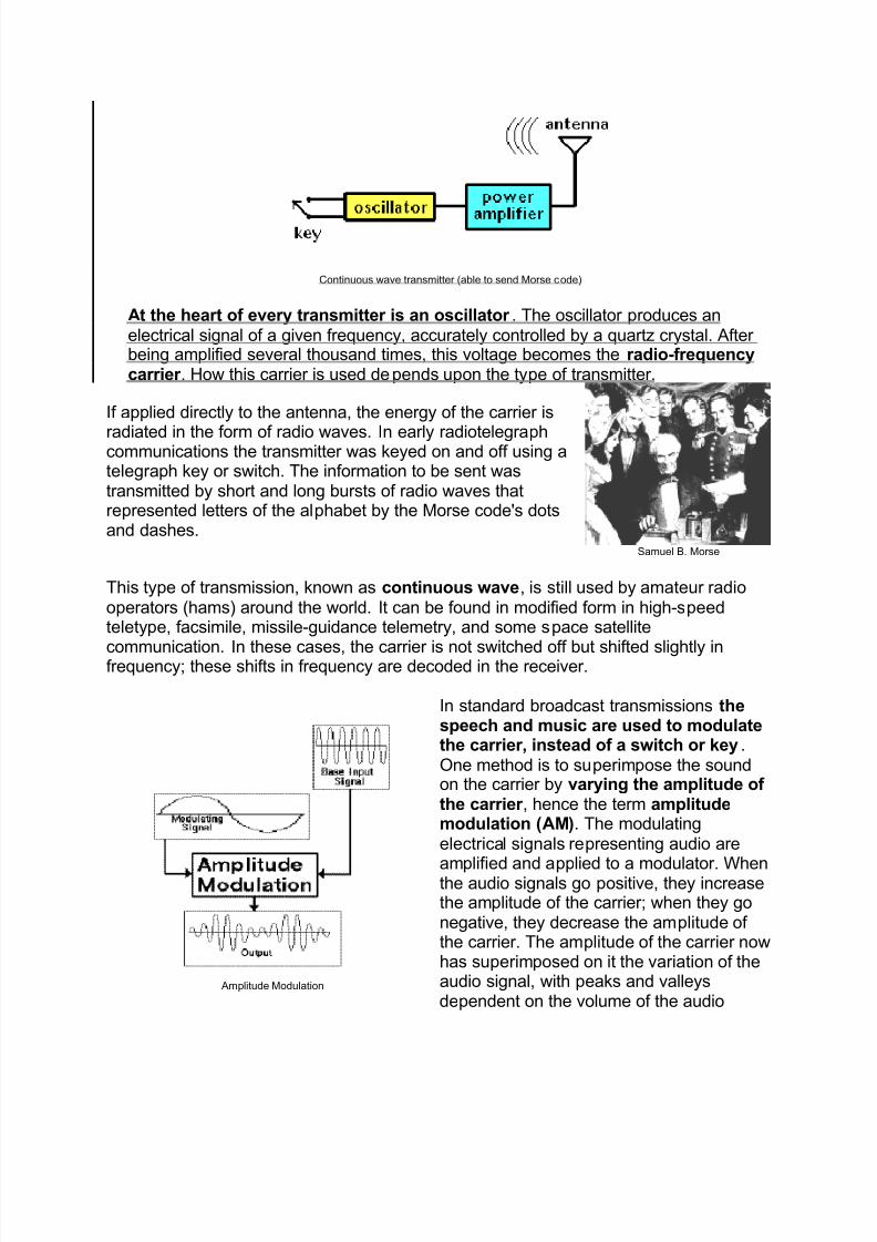
Continuous wave transmitter (able to send Morse code)
At the heart of every transmitter is an oscillator . The oscillator produces anelectrical signal of a given frequency, accurately controlled by a quartz crystal. After being amplified several thousand times, this voltage becomes the radio-frequencycarrier . How this carrier is used depends upon the type of transmitter.
If applied directly to the antenna, the energy of the carrier is
radiated in the form of radio waves. In early radiotelegraphcommunications the transmitter was keyed on and off using atelegraph key or switch. The information to be sent wastransmitted by short and long bursts of radio waves thatrepresented letters of the alphabet by the Morse code's dotsand dashes.
Samuel B. Morse
This type of transmission, known as continuous wave, is still used by amateur radiooperators (hams) around the world. It can be found in modified form in high-speedteletype, facsimile, missile-guidance telemetry, and some space satellite
communication.In these cases, the carrier is not switched off but shifted slightly infrequency; these shifts in frequency are decoded in the receiver.
Amplitude Modulation
In standard broadcast transmissions thespeech and music are used to modulatethe carrier, instead of a switch or key.One method is to superimpose the soundon the carrier by varying the amplitude of the carrier , hence the term amplitudemodulation (AM). The modulatingelectrical signals representing audio are
amplified and applied to a modulator. Whenthe audio signals go positive, they increasethe amplitude of the carrier; when they gonegative, they decrease the amplitude of the carrier. The amplitude of the carrier nowhas superimposed on it the variation of theaudio signal, with peaks and valleysdependent on the volume of the audio
8/6/2019 One Night I Walked Home Very Late and Fell Asleep in Somebody
http://slidepdf.com/reader/full/one-night-i-walked-home-very-late-and-fell-asleep-in-somebody 3/34
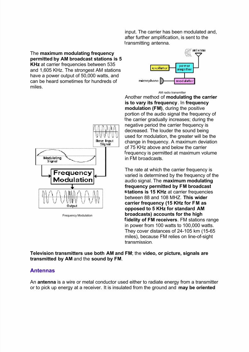
input. The carrier has been modulated and,after further amplification, is sent to theransmitting antenna.
The maximum modulating frequencypermitted by AM broadcast stations is 5KHz at carrier frequencies between 535
and 1,605 KHz. The strongest AM stationshave a power output of 50,000 watts, andcan be heard sometimes for hundreds of miles.
AM radio transmitter
Frequency Modulation
Another method of modulating the carrier is to vary its frequency. In frequencymodulation (FM), during the positiveportion of the audio signal the frequency of he carrier gradually increases; during the
negative period the carrier frequency isdecreased. The louder the sound beingused for modulation, the greater will be thechange in frequency. A maximum deviationof 75 KHz above and below the carrier requency is permitted at maximum volumein FM broadcasts.
The rate at which the carrier frequency isvaried is determined by the frequency of theaudio signal. The maximum modulating
frequency permitted by FM broadcasttations is 15 KHz at carrier frequencies
between 88 and 108 MHZ. This wider carrier frequency (15 KHz for FM asopposed to 5 KHz for standard AM broadcasts) accounts for the highidelity of FM receivers. FM stations range
in power from 100 watts to 100,000 watts.They cover distances of 24-105 km (15-65miles), because FM relies on line-of-sighttransmission.
Television transmitters use both AM and FM; the video, or picture, signals aretransmitted by AM and the sound by FM.
Antennas
An antenna is a wire or metal conductor used either to radiate energy from a transmitter or to pick up energy at a receiver. It is insulated from the ground and may be oriented
8/6/2019 One Night I Walked Home Very Late and Fell Asleep in Somebody
http://slidepdf.com/reader/full/one-night-i-walked-home-very-late-and-fell-asleep-in-somebody 4/34
vertically or horizontally; this is also known as its polarity. An AM broadcastantenna is vertically polarized, requiring the receiving antenna to be located verticallyalso, like those found on automobiles. Television and FM broadcast transmitterstraditionally have used a horizontal polarization antenna, although many FM and
some TV stations are now circularly (horizontally and vertically) polarized.
Wavelength
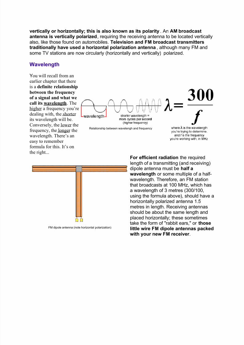
You will recall from an
earlier chapter that thereis a definite relationship
between the frequency
of a signal and what we
call its wavelength. Thehigher a frequency you¶re
dealing with, the shorter
its wavelength will be.Conversely, the lower thefrequency, the longer thewavelength. There¶s an
easy to remember formula for this. It¶s on
the right...
Relationship between wavelengh and frequency
FM dipole antenna (note horizontal polarization)
For efficient radiation the required
length of a transmitting (and receiving)dipole antenna must be half awavelength or some multiple of a half-
wavelength. Therefore, an FM stationthat broadcasts at 100 MHz, which hasa wavelength of 3 metres (300/100,using the formula above), should have ahorizontally polarized antenna 1.5metres in length. Receiving antennasshould be about the same length andplaced horizontally; these sometimestake the form of "rabbit ears," or thoselittle wire FM dipole antennas packedwith your new FM receiver .
8/6/2019 One Night I Walked Home Very Late and Fell Asleep in Somebody
http://slidepdf.com/reader/full/one-night-i-walked-home-very-late-and-fell-asleep-in-somebody 5/34
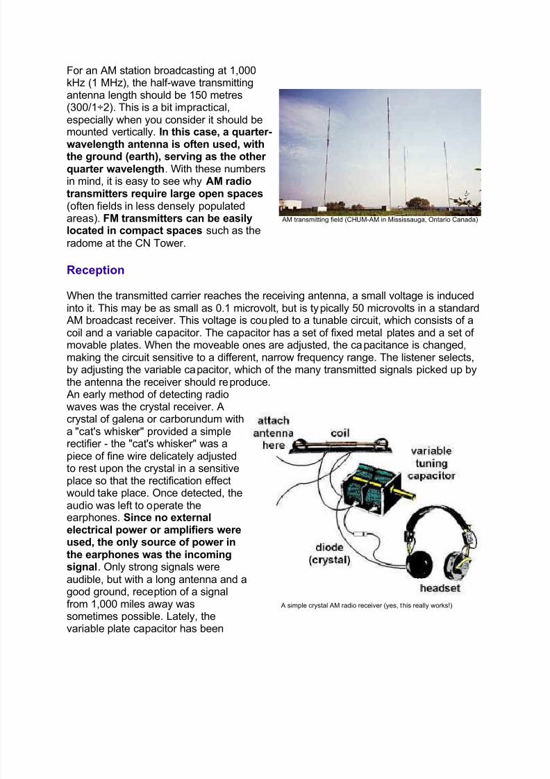
For an AM station broadcasting at 1,000kHz (1 MHz), the half-wave transmittingantenna length should be 150 metres(300/1÷2). This is a bit impractical,especially when you consider it should be
mounted vertically.In this case, a quarter-wavelength antenna is often used, with
the ground (earth), serving as the other quarter wavelength. With these numbersin mind, it is easy to see why AM radiotransmitters require large open spaces (often fields in less densely populatedareas). FM transmitters can be easilylocated in compact spaces such as the
radome at the CN Tower.
AM transmitting field (CHUM-AM in Mississauga, Ontario Canada)
Reception
When the transmitted carrier reaches the receiving antenna, a small voltage is inducedinto it. This may be as small as 0.1 microvolt, but is typically 50 microvolts in a standard
AM broadcast receiver. This voltage is coupled to a tunable circuit, which consists of acoil and a variable capacitor. The capacitor has a set of fixed metal plates and a set of movable plates. When the moveable ones are adjusted, the capacitance is changed,making the circuit sensitive to a different, narrow frequency range. The listener selects,by adjusting the variable capacitor, which of the many transmitted signals picked up bythe antenna the receiver should reproduce.
An early method of detecting radio
waves was the crystal receiver. Acrystal of galena or carborundum witha "cat's whisker" provided a simplerectifier - the "cat's whisker" was apiece of fine wire delicately adjustedto rest upon the crystal in a sensitiveplace so that the rectification effectwould take place. Once detected, theaudio was left to operate theear phones. Since no externalelectrical power or amplifiers were
used, the only source of power inthe earphones was the incomingsignal. Only strong signals wereaudible, but with a long antenna and agood ground, reception of a signalfrom 1,000 miles away wassometimes possible. Lately, thevariable plate capacitor has been
A simple crystal AM radio receiver (yes, this really works!)
8/6/2019 One Night I Walked Home Very Late and Fell Asleep in Somebody
http://slidepdf.com/reader/full/one-night-i-walked-home-very-late-and-fell-asleep-in-somebody 6/34
supplanted by a variable capacitancediode (varicap) or variable reactancediode (varactor). These changecapacitance not mechanically, but inresponse to an electrical voltage at
their inputs.
Following the development of the triode vacuum tube, increasing selectivity (ease of separating individual stations), sensitivity (how well distant stations can bereceived), and audio output power was possible. The tuned-radio-frequency (TRF)process involved several stages of radio-frequency amplification before thedetection stage. In early receivers each of these stages had to be separately tuned tothe incoming frequency - a difficult task at the best of times. Even after single-dial tuningwas achieved by ganging together the stages, the TRF was susceptible to breaking intooscillation and was unsuitable for tuning over a wide range of frequencies. The principleis still used, however, in some modern shipboard emergency receivers and fixed-
frequency microwave receivers.
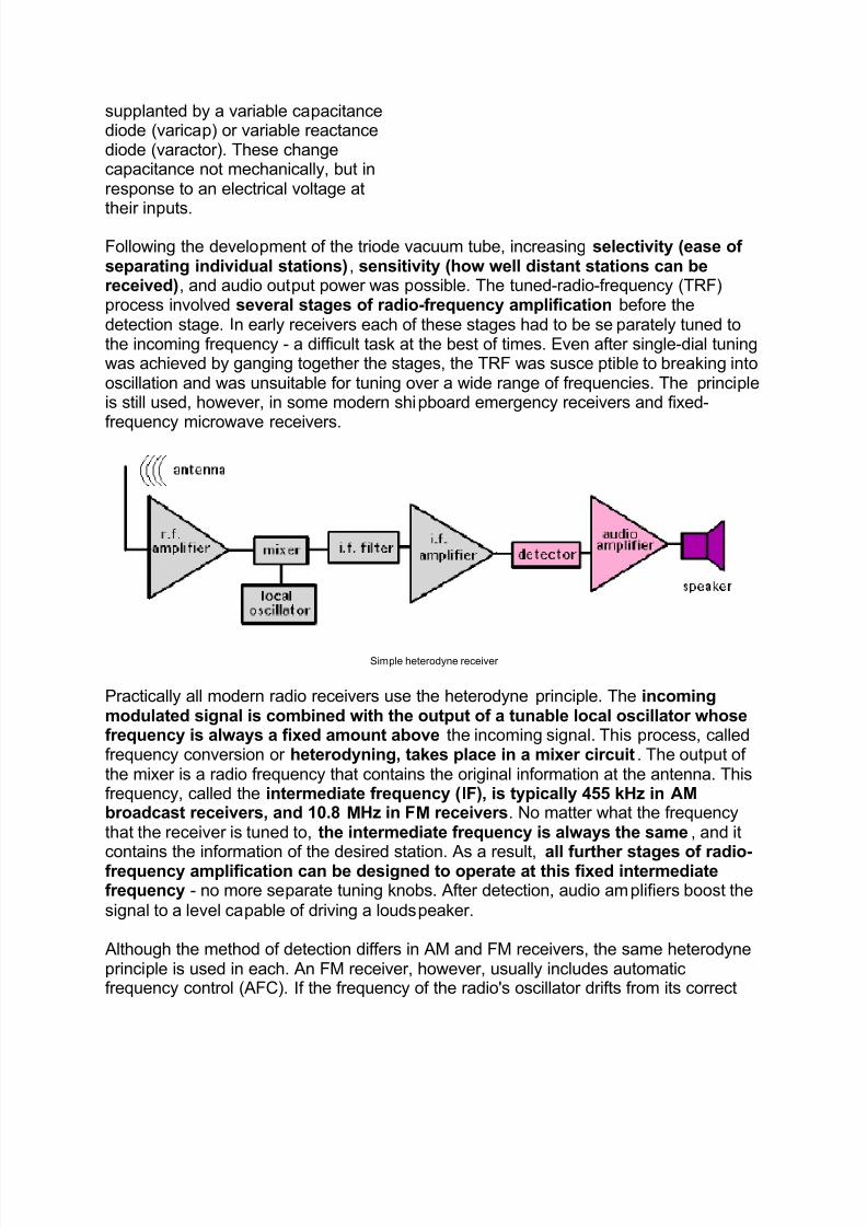
Simple heterodyne receiver
Practically all modern radio receivers use the heterodyne principle. The incomingmodulated signal is combined with the output of a tunable local oscillator whosefrequency is always a fixed amount above the incoming signal. This process, calledfrequency conversion or heterodyning, takes place in a mixer circuit. The output of the mixer is a radio frequency that contains the original information at the antenna. Thisfrequency, called the intermediate frequency (IF), is typically 455 kHz in AM broadcast receivers, and 10.8 MHz in FM receivers. No matter what the frequencythat the receiver is tuned to, the intermediate frequency is always the same, and it
contains the information of the desired station. As a result, all further stages of radio-frequency amplification can be designed to operate at this fixed intermediatefrequency - no more separate tuning knobs. After detection, audio amplifiers boost the
signal to a level capable of driving a loudspeaker.
Although the method of detection differs in AM and FM receivers, the same heterodyneprinciple is used in each. An FM receiver, however, usually includes automaticfrequency control (AFC). If the frequency of the radio's oscillator drifts from its correct
8/6/2019 One Night I Walked Home Very Late and Fell Asleep in Somebody
http://slidepdf.com/reader/full/one-night-i-walked-home-very-late-and-fell-asleep-in-somebody 7/34
value, the station will fade. To avoid this problem, a voltage is developed at the detector and fed back to the local oscillator. This voltage is used to change automatically thefrequency output of the oscillator to maintain the proper intermediate frequency.
Both AM and FM receivers use automatic gain control (AGC), sometimes called
automatic volume control (AVC).If a strong station is tuned in, the volume of the soundwould be overwhelming if the volume control had previously been set for a weak station.
This drawback is overcome by the use of negative feedback - a voltage is developed atthe detector and used to reduce automatically the gain, or amplification, of the IFamplifiers.
The prime advantage of FM, in addition to its fidelity, is its immunity to electricalnoise, which imposes itself on an AM signal by increasing the amplitude of thesignal. This effect shows up in AM as a crackling noise. FM doesn't have thisproblem, because it decodes only the frequency variations, and has a limiter circuitthat restricts any amplitude variations that may result from such interference.
Sidebands
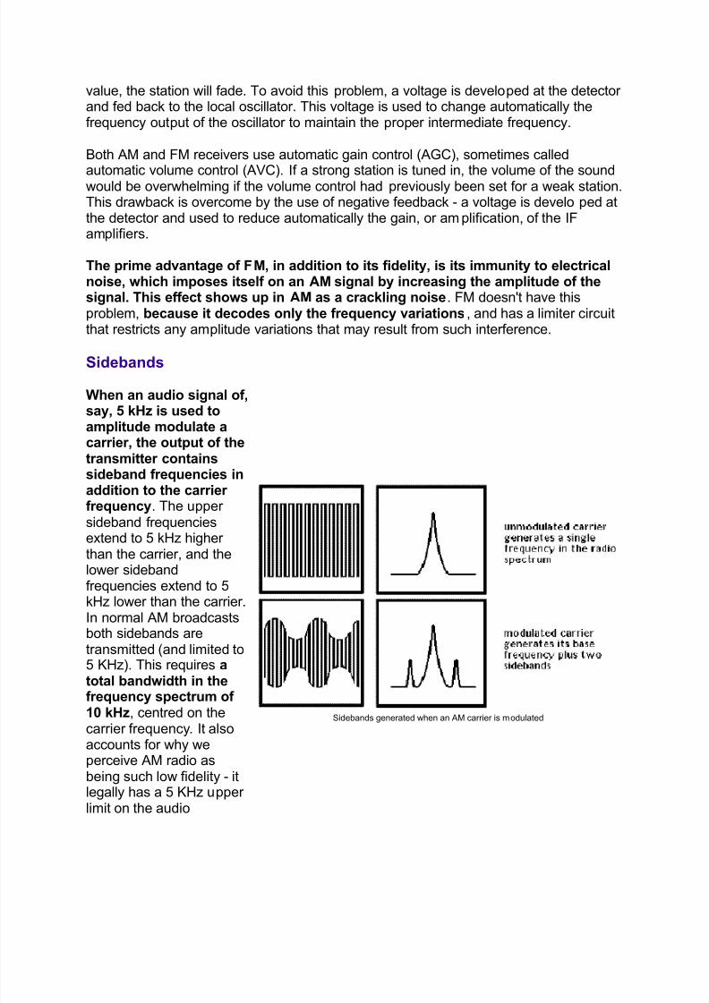
When an audio signal of,say, 5 kHz is used toamplitude modulate acarrier, the output of thetransmitter containssideband frequencies inaddition to the carrier frequency. The upper
sideband frequenciesextend to 5 kHz higher than the carrier, and thelower sidebandfrequencies extend to 5kHz lower than the carrier.In normal AM broadcastsboth sidebands aretransmitted (and limited to5 KHz). This requires atotal bandwidth in the
frequency spectrum of 10 kHz, centred on thecarrier frequency. It alsoaccounts for why weperceive AM radio asbeing such low fidelity - itlegally has a 5 KHz upper limit on the audio
Sidebands generated when an AM carrier is modulated
8/6/2019 One Night I Walked Home Very Late and Fell Asleep in Somebody
http://slidepdf.com/reader/full/one-night-i-walked-home-very-late-and-fell-asleep-in-somebody 8/34
frequences it can transmit.
The audio signal, however, is contained in (and may be retrieved from) either the upper or lower sideband. Furthermore, the carrier itself contains no useful information.Therefore, the only part that needs to be transmitted is one of the sidebands. A
system designed to do this is called "single sideband suppressed carrier"(abbreviated SSB). This is an important system because it requires only half of thebandwidth needed for ordinary AM, thus allowing more channels to be assigned in anygiven portion of the frequency spectrum. Also, because of the reduced power requirements, a 110 watt SSB transmitter may have a range as great as that of a 1,000watt conventional AM transmitter. Most ham radios, commercial radiotelephones, andmarine-band radios, as well as citizens band radios, use SSB systems. Receivers for such systems are more complex, however - they must reinsert the non-transmitted carrier before successful heterodyning can take place.
The concept of sidebands will be important to us when we look at how a television
channel is transmitted.
Television
Transmission
When considering the transmission of television pictures, we must recall certain aspectsof the video signal. The scene is scanned in about 1/30 of a second, and during thattime about 280,000 picture elements must be covered. This number corresponds toscanning at the extremely high rate of 4,200,000 Hz (with twice that number of pictureelements) per second.
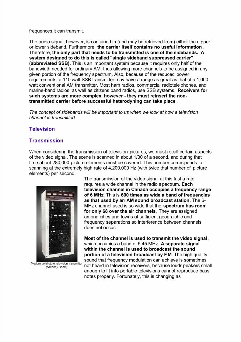
Modern solid state television transmitter ( courtesy Harris)
The transmission of the video signal at this fast a raterequires a wide channel in the radio spectrum. Eachtelevision channel in Canada occupies a frequency rangeof 6 MHz. This is 600 times as wide a band of frequenciesas that used by an AM sound broadcast station. The 6-MHz channel used is so wide that the spectrum has roomfor only 68 over the air channels. They are assigned
among cities and towns at sufficient geographic andfrequency separations so interference between channelsdoes not occur.
Most of the channel is used to transmit the video signal ,which occupies a band of 5.45 MHz. A separate signalwithin the channel is used to broadcast the soundportion of a television broadcast by FM. The high qualitysound that frequency modulation can achieve is sometimesnot heard in television receivers, because loudspeakers smallenough to fit into portable televisions cannot reproduce bassnotes properly. Fortunately, this is changing as
8/6/2019 One Night I Walked Home Very Late and Fell Asleep in Somebody
http://slidepdf.com/reader/full/one-night-i-walked-home-very-late-and-fell-asleep-in-somebody 9/34
manufacturers realize there is a market for high fidelitytelevision audio.
For the video signal to be transmitted over the air, it is carried by a carrier signal. This isan alternating current of very high frequency. On channel 2, for example, the picture
carrier frequency is 55.25 MHz. This signal is generated initially by a quartz crystaloscillator at a lower frequency, which is multiplied and amplified until it reaches a power level of many kilowatts. The video signal controls one of the amplifiers, changing itspower output. The amplitude modulated carrier current is directed through thetransmitting antenna, designed to radiate waves in the horizontal direction.
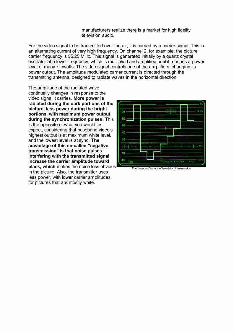
The amplitude of the radiated wavecontinually changes in response to thevideo signal it carries. More power isradiated during the dark portions of thepicture, less power during the bright
portions, with maximum power outputduring the synchronization pulses. This
is the opposite of what you would firstexpect, considering that baseband video'shighest output is at maximum white level,and the lowest level is at sync. Theadvantage of this so-called "negativetransmission" is that noise pulsesinterfering with the transmitted signalincrease the carrier amplitude towardblack, which makes the noise less obviousin the picture. Also, the transmitter usesless power, with lower carrier amplitudes,for pictures that are mostly white.
The "inverted" nature of television transmission
8/6/2019 One Night I Walked Home Very Late and Fell Asleep in Somebody
http://slidepdf.com/reader/full/one-night-i-walked-home-very-late-and-fell-asleep-in-somebody 10/34
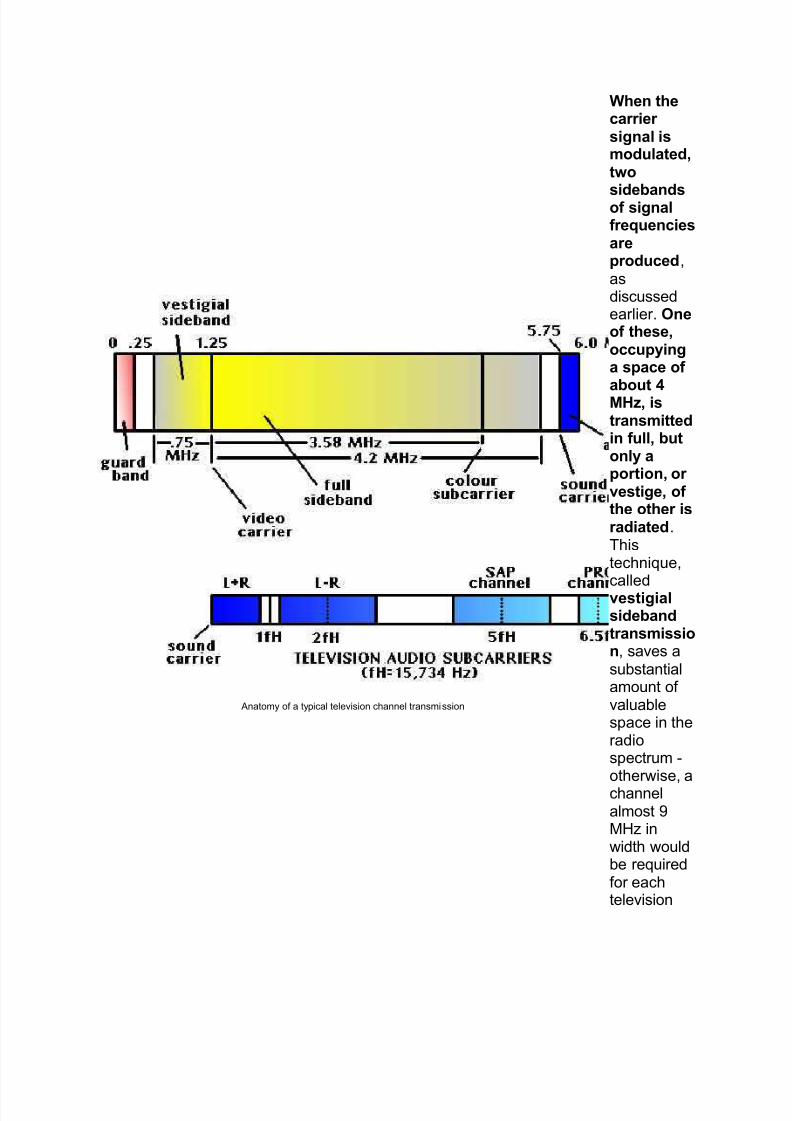
Anatomy of a typical television channel transmission
When thecarrier signal ismodulated,two
sidebandsof signalfrequenciesareproduced,asdiscussedearlier. Oneof these,occupyinga space of
about 4MHz, istransmittedin full, butonly aportion, or vestige, of the other isradiated.Thistechnique,calledvestigialsidebandtransmission, saves asubstantialamount of valuablespace in theradiospectrum -otherwise, achannelalmost 9MHz inwidth wouldbe requiredfor eachtelevision
8/6/2019 One Night I Walked Home Very Late and Fell Asleep in Somebody
http://slidepdf.com/reader/full/one-night-i-walked-home-very-late-and-fell-asleep-in-somebody 11/34
signal.
Video signals transmitted in this way have the picture carrier at 1.25 MHz above thelower frequency boundary (this area being used by the smaller sideband), and extendup to 4 MHz beyond the carrier to 5.25 MHz. The colour subcarrier is placed at 3.58
MHz above the picture carrier (about 4.8 MHz within the channel). The sound carrier isplaced .25 MHz (25 KHz) below the upper 6 MHz boundary; it is a conventional FMsignal, with a bandwidth of about 50 KHz (+/- 25 KHz given 100% modulation).
What Are All Those Audio Signals?
Television audio¶s complexity has increased somewhat since the monaural days of the1950s. It now has a series of subcarriers, piggybacked onto the main channel¶s audio,to allow us to receive such things as stereo, SAP and PRO.
Stereo is sent to the television set by using two channels - one of them is Left+Right
(monaural) and the other is Left-Right (the difference between the left and right soundinformation.) This means that small, inexpensive sets can receive mono TV audio, whilemore expensive units can extract full stereo by using a matrix to decode the discretechannels.
SAP is an acronym for Second Audio Program, and was originally intended to providea way for TV stations to broadcast in two languages at once. Many stations use SAP for descriptive video services (narration of action on the screen for the visually impaired.)Other stations rebroadcast weather information, or use it as a "barker" channel, acontinuously running advertisement.
PRO is the PROfessional channel of audio. This is for internal use by TV stations for such things as cueing reporters in the field, and is sometimes used for telemetry thatrelays information about a station¶s transmitter, back to master control.
Reception
The radio waves used in television broadcasting travel in straight lines, are
intercepted when they strike any large object, and are weakened when they meet thehorizon. To reach the largest possible number of viewers, therefore, the transmittingantenna must be located as high above the local terrain as possible. The primaryservice area of a television station thus seldom extends beyond 50 miles , although
marginal reception is often possible at 100 miles if a highly sensitive receiving antennais used.
Ghosts
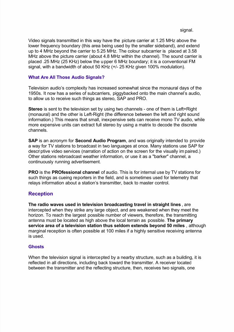
When the television signal is intercepted by a nearby structure, such as a building, it isreflected in all directions, including back toward the transmitter. A receiver locatedbetween the transmitter and the reflecting structure, then, receives two signals, one
8/6/2019 One Night I Walked Home Very Late and Fell Asleep in Somebody
http://slidepdf.com/reader/full/one-night-i-walked-home-very-late-and-fell-asleep-in-somebody 12/34
directly from the transmitter as intended, the other by reflection from the structure. Thereflected signal, having travelled a greater distance, arrives later than the direct signal.Radio waves cover about 300 metres in amillionth of a second.
Hence, if the reflectedpath is longer thanthe direct path by 3km, for example, thereflected signalarrives 10 millionthsof a second later than the directsignal. As notedabove, the scanningof a line takes about
60 millionths of asecond. So, during
the scanning of eachline, both the directand the reflectedsignals produceimages, the reflectedsignal producing a"ghost" of theintended image. Inthis example, theghost image wouldbe to the right of theintended image byabout one-sixth of the width of thepicture. Conditions inwhich a reflectedsignal exists, calledmultipath reception,are common in built-up city areas havingmany tall buildings.
How ghosts happen
8/6/2019 One Night I Walked Home Very Late and Fell Asleep in Somebody
http://slidepdf.com/reader/full/one-night-i-walked-home-very-late-and-fell-asleep-in-somebody 13/34
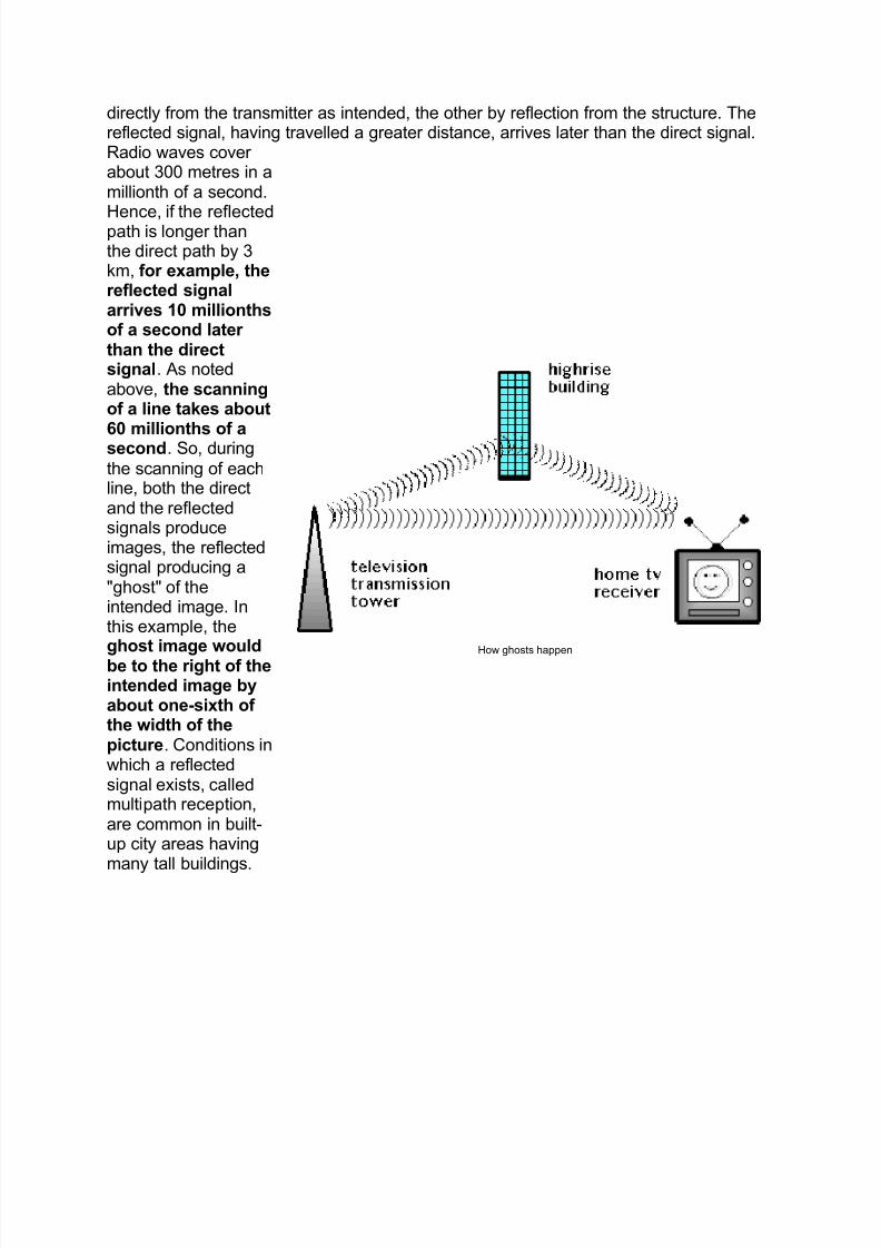
Directional receiving antenna (compare with "rabbit ears")
To lessen the effect, thereceiving antenna must be ashigh as possible and orientedso it discriminates against thereflected signal. One method
of avoiding reflections is tofeed many receivers by coaxialcable from a single antenna(community antenna) locatedhigh above surroundingstructures, where it is free fromreflected signals.
The typical outdoor receiving antenna isconstructed of several
parallel horizontal metalrods of different lengthsspaced one behind theother. Such an array hasdirectional properties,displaying maximum sensitivityon the line at right angles tothe metal rods. For localreception, a less elaborateantenna will do, such as theextendable telescoping rodsprovided in portable televisionreceivers or the use of so-called "rabbit ears."
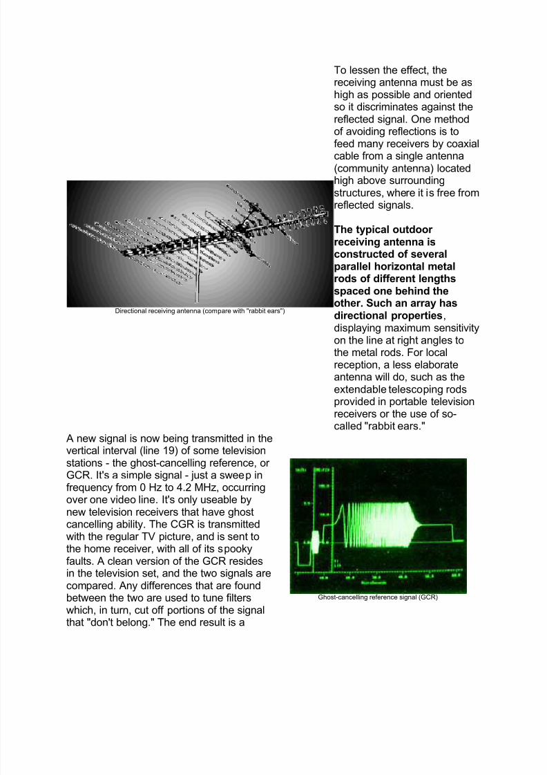
A new signal is now being transmitted in thevertical interval (line 19) of some televisionstations - the ghost-cancelling reference, or GCR. It's a simple signal - just a sweep infrequency from 0 Hz to 4.2 MHz, occurringover one video line. It's only useable bynew television receivers that have ghostcancelling ability. The CGR is transmittedwith the regular TV picture, and is sent tothe home receiver, with all of its spookyfaults. A clean version of the GCR residesin the television set, and the two signals arecompared. Any differences that are foundbetween the two are used to tune filterswhich, in turn, cut off portions of the signalthat "don't belong." The end result is a
Ghost-cancelling reference signal (GCR)
8/6/2019 One Night I Walked Home Very Late and Fell Asleep in Somebody
http://slidepdf.com/reader/full/one-night-i-walked-home-very-late-and-fell-asleep-in-somebody 14/34
clean picture.
Black and White Television Sets
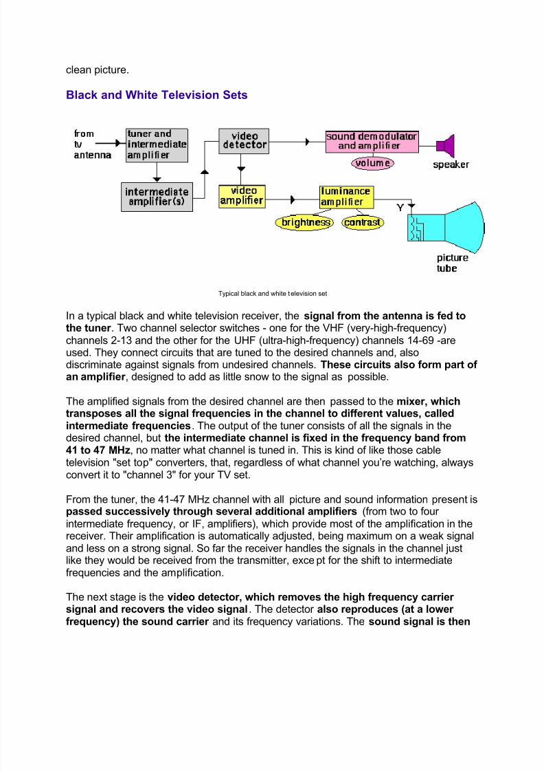
Typical black and white television set
In a typical black and white television receiver, the signal from the antenna is fed tothe tuner . Two channel selector switches - one for the VHF (very-high-frequency)channels 2-13 and the other for the UHF (ultra-high-frequency) channels 14-69 -areused. They connect circuits that are tuned to the desired channels and, alsodiscriminate against signals from undesired channels. These circuits also form part of an amplifier , designed to add as little snow to the signal as possible.
The amplified signals from the desired channel are then passed to the mixer, whichtransposes all the signal frequencies in the channel to different values, calledintermediate frequencies. The output of the tuner consists of all the signals in thedesired channel, but the intermediate channel is fixed in the frequency band from41 to 47 MHz, no matter what channel is tuned in. This is kind of like those cabletelevision "set top" converters, that, regardless of what channel you¶re watching, alwaysconvert it to "channel 3" for your TV set.
From the tuner, the 41-47 MHz channel with all picture and sound information present ispassed successively through several additional amplifiers (from two to four intermediate frequency, or IF, amplifiers), which provide most of the amplification in the
receiver. Their amplification is automatically adjusted, being maximum on a weak signaland less on a strong signal. So far the receiver handles the signals in the channel justlike they would be received from the transmitter, except for the shift to intermediatefrequencies and the amplification.
The next stage is the video detector, which removes the high frequency carrier signal and recovers the video signal. The detector also reproduces (at a lower frequency) the sound carrier and its frequency variations. The sound signal is then
8/6/2019 One Night I Walked Home Very Late and Fell Asleep in Somebody
http://slidepdf.com/reader/full/one-night-i-walked-home-very-late-and-fell-asleep-in-somebody 15/34
separated from the picture signal and passes through a frequency detector,which recovers the audio signal. This signal is amplified further and fed to theloudspeaker, where it re-creates the accompanying sound. The picture signal fromthe video detector is used in the normal fashion for display on the CRT of the
television receiver.
Colour Television Sets
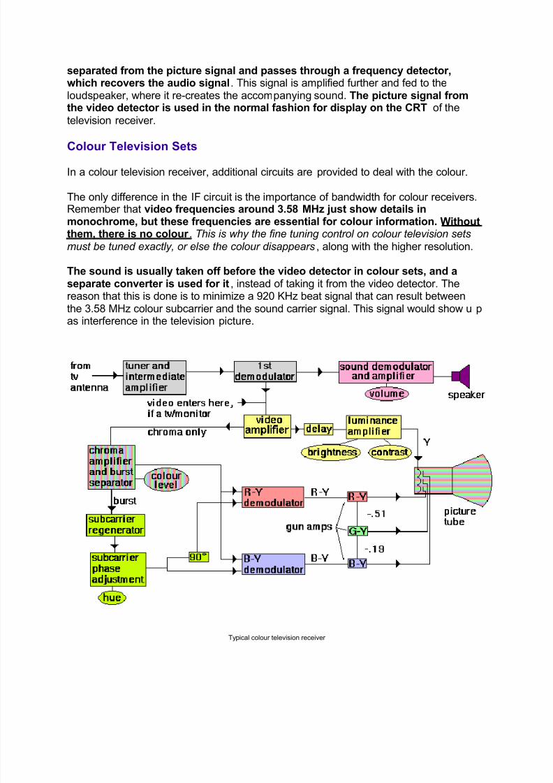
In a colour television receiver, additional circuits are provided to deal with the colour.
The only difference in the IF circuit is the importance of bandwidth for colour receivers.Remember that video frequencies around 3.58 MHz just show details inmonochrome, but these frequencies are essential for colour information. Withoutthem, there is no colour . This is why the fine tuning control on colour television setsmust be tuned exactly, or else the colour disappears, along with the higher resolution.
The sound is usually taken off before the video detector in colour sets, and aseparate converter is used for it, instead of taking it from the video detector. Thereason that this is done is to minimize a 920 KHz beat signal that can result betweenthe 3.58 MHz colour subcarrier and the sound carrier signal. This signal would show up as interference in the television picture.
Typical colour television receiver
8/6/2019 One Night I Walked Home Very Late and Fell Asleep in Somebody
http://slidepdf.com/reader/full/one-night-i-walked-home-very-late-and-fell-asleep-in-somebody 16/34
The output from the video detector is sent to two places: a series of colour circuits, and a luminance output amplifier .
The luminance amplifier also serves as a cutoff filter for frequencies above 3.2 MHz,
thus removing all colour information from the luminance video signal and, alas, some of
the shar pness and detail. On this amplifier is where you will find your brightness and contrast controls.
In the colour recovery circuits, several things happen. First, the video detector'soutput is sent through a colour "band pass" filter , which leaves us with just the
chrominance information - the luminance has been removed. This chroma outputcontains both the colour information for the picture, and the colour burst. It is then sentto a burst separator to detect the phase and level of the colour burst. This is whereyou¶ll find your "colour" control . Now we'll have a reference for the colours within thepicture, which is sent to a crystal oscillator which generates constant 3.58 MHzsubcarrier of the correct phase. This oscillator¶s phase can be adjusted - this is your
hue control . The oscillator is used with two colour demodulators to recover the R-Yand B-Y colour difference signals. The continuous wave subcarrier is delayed by 90degrees of phase before it enters the R-Y demodulator. The R-Y and B-Y signals arecombined further to recover the G-Y signal.
All three signals are then sent to the colour picture tube's grids. There, they arecombined with three luminance drive signals in the correct proportions, giving us our familiar RGB signals for driving the electron guns within the picture tube to re-create thecolour television picture.
Try This At Home!
Turn on a colour TV set that is a slightly older. One that doesn¶t have a whole bunch of "automatic tuning" controls on it, but instead has a fine tuning knob or pushbuttons, soyou can play around. It can be hooked to cable TV or an antenna.
Now, tune in your favourite (or, perhaps, your most hated) TV channel. Play with thefine tuning controls. Notice how the colour kicks out with the high resolution detail in thepicture. Eventually the sound becomes a mess, too, and may even get a shar p, 60 Hz"buzz" in it.
While you¶re tuning around, look at the "Anatomy of a TV Channel" diagram in these
notes and see where the sound and picture are, and notice that, at one point, the "buzz"you¶re hearing is actually the sound portion of your TV set picking up the vertical syncpulses of the video. Cool!
When you¶re done, PUT THE SET BACK THE WAY YOU FOUND IT - be nice to your roomies.
8/6/2019 One Night I Walked Home Very Late and Fell Asleep in Somebody
http://slidepdf.com/reader/full/one-night-i-walked-home-very-late-and-fell-asleep-in-somebody 17/34
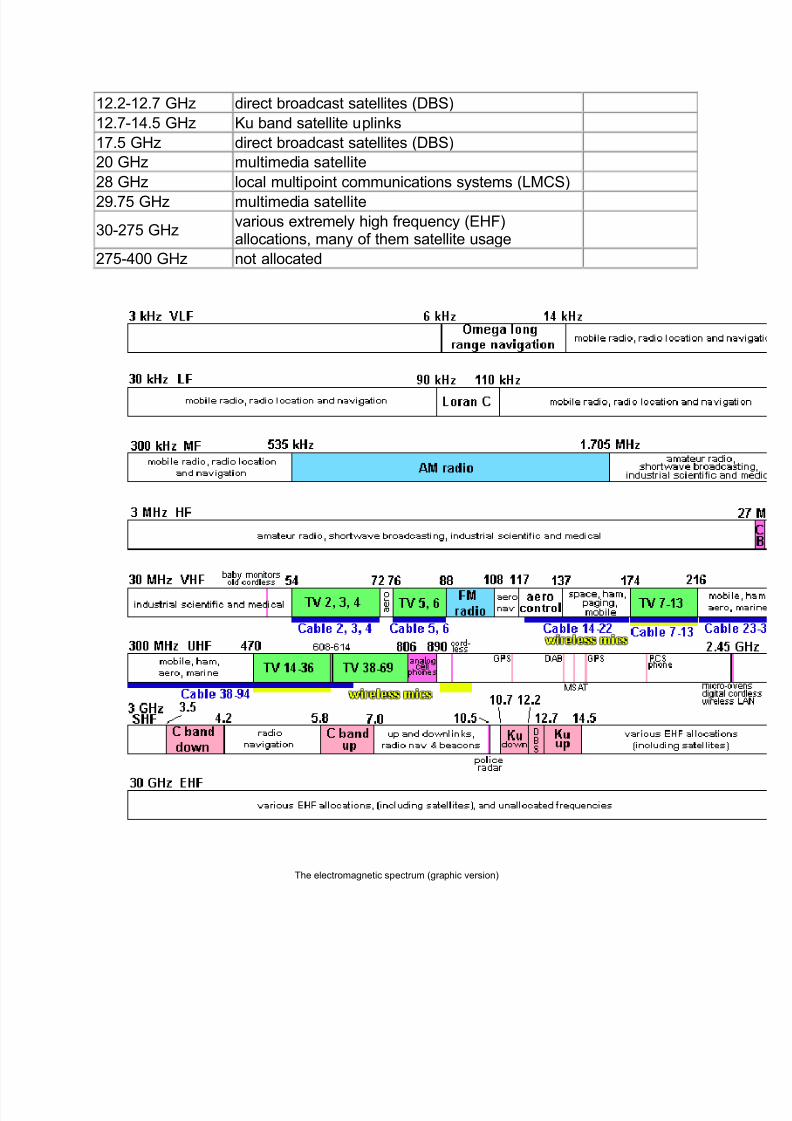
The Electromagnetic Spectrum
Electromagnetic radio waves use the radio spectrum. The lowest frequencies havethe longest radio waves; the highest frequencies, the shortest waves.
The spectrum is divided into several frequency bands, each having characteristicspeculiar to it which more or less determine the usage appropriate to that band. Eachband has been assigned by international agreement at a World Administrative RadioConference (WARC) to one or more radio services or specific usages. Sponsored bythe International Telecommunication Union (an agency of the United Nations), WARCsare held to extend, review and revise frequency allocations among the various uses.
After such a conference and from time to time between conferences as Canada's needschange, Industry Canada allocates specific frequency bands to services to satisfydomestic communications requirements. A more detailed presentation of theseallocations, including footnotes, is provided in Canada's Table of Frequency Allocations
published by Industry Canada. It can be found online athttp://strategis.ic.gc.ca/epic/internet/insmt-gst.nsf/vwGeneratedInterE/sf07031e.html
The radio spectrum is used by broadcasters, taxis, building and other constructiontrades, air transport, radio amateurs, marine transport, telecommunications carriers,electrical power utilities, trucking companies, police, CB operators and federal,provincial and municipal departments and agencies. It's a busy place...
Try This At Home! Listen To The World!
Find a friend with a "radio scanner" and have a listen to all the things that are sent in the
radio spectrum. A good scanner can pick up most of the stuff in the spectrum chart.
Find a friend with a shortwave receiver and listen to the world! It¶s neat to hear radiobroadcasts from, say Luxembourg.
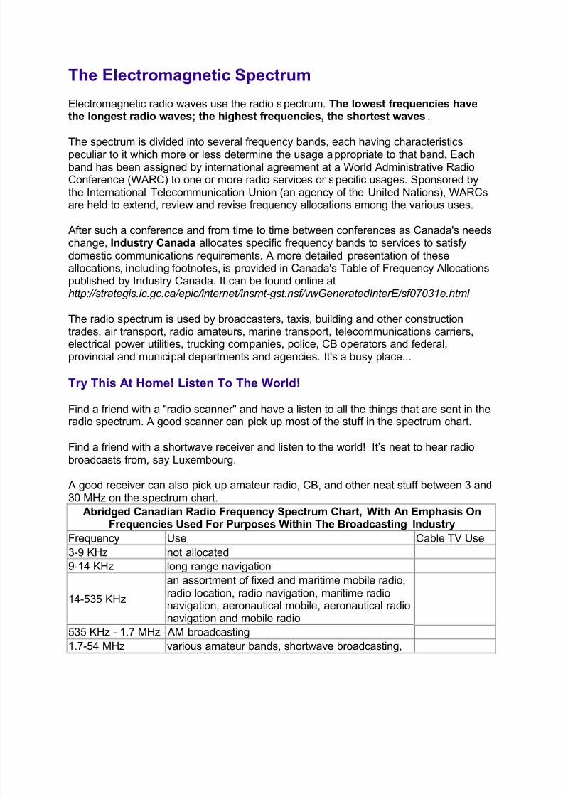
A good receiver can also pick up amateur radio, CB, and other neat stuff between 3 and30 MHz on the spectrum chart.
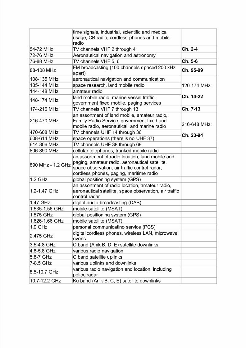
Abridged Canadian Radio Frequency Spectrum Chart, With An Emphasis OnFrequencies Used For Purposes Within The Broadcasting Industry
Frequency Use Cable TV Use
3-9 KHz not allocated
9-14 KHz long range navigation
14-535 KHz
an assortment of fixed and maritime mobile radio,radio location, radio navigation, maritime radionavigation, aeronautical mobile, aeronautical radionavigation and mobile radio
535 KHz - 1.7 MHz AM broadcasting
1.7-54 MHz various amateur bands, shortwave broadcasting,
8/6/2019 One Night I Walked Home Very Late and Fell Asleep in Somebody
http://slidepdf.com/reader/full/one-night-i-walked-home-very-late-and-fell-asleep-in-somebody 18/34
time signals, industrial, scientific and medicalusage, CB radio, cordless phones and mobileradio
54-72 MHz TV channels VHF 2 through 4 Ch. 2-4
72-76 MHz Aeronautical navigation and astronomy
76-88 MHz TV channels VHF 5, 6 Ch. 5-6
88-108 MHz FM broadcasting (100 channels spaced 200 kHzapart)
Ch. 95-99
108-135 MHz aeronautical navigation and communication
120-174 MHz:
Ch. 14-22
135-144 MHz space research, land mobile radio
144-148 MHz amateur radio
148-174 MHz land mobile radio, marine vessel traffic,government fixed mobile, paging services
174-216 MHz TV channels VHF 7 through 13 Ch. 7-13
216-470 MHz
an assortment of land mobile, amateur radio,
Family Radio Service, government fixed andmobile radio, aeronautical, and marine radio 216-648 MHz:
Ch. 23-94 470-608 MHz TV channels UHF 14 through 36
608-614 MHz space operations (there is no UHF 37)
614-806 MHz TV channels UHF 38 through 69
806-890 MHz cellular telephones, trunked mobile radio
890 MHz - 1.2 GHz
an assortment of radio location, land mobile andpaging, amateur radio, aeronautical satellite,space observation, air traffic control radar,cordless phones, paging, maritime radio
1.2 GHz global positioning system (GPS)
1.2-1.47 GHz
an assortment of radio location, amateur radio,aeronautical satellite, space observation, air trafficcontrol radar
1.47 GHz digital audio broadcasting (DAB)
1.535-1.56 GHz mobile satellite (MSAT)
1.575 GHz global positioning system (GPS)
1.626-1.66 GHz mobile satellite (MSAT)
1.9 GHz personal communicatino service (PCS)
2.475 GHz digital cordless phones, wireless LAN, microwaveovens
3.5-4.8 GHz C band (Anik B, D, E) satellite downlinks 4.8-5.8 GHz various radio navigation
5.8-7 GHz C band satellite uplinks
7-8.5 GHz various uplinks and downlinks
8.5-10.7 GHz various radio navigation and location, includingpolice radar
10.7-12.2 GHz Ku band (Anik B, C, E) satellite downlinks
8/6/2019 One Night I Walked Home Very Late and Fell Asleep in Somebody
http://slidepdf.com/reader/full/one-night-i-walked-home-very-late-and-fell-asleep-in-somebody 19/34
12.2-12.7 GHz direct broadcast satellites (DBS)
12.7-14.5 GHz Ku band satellite uplinks
17.5 GHz direct broadcast satellites (DBS)
20 GHz multimedia satellite
28 GHz local multipoint communications systems (LMCS)
29.75 GHz multimedia satellite
30-275 GHz various extremely high frequency (EHF)allocations, many of them satellite usage
275-400 GHz not allocated
The electromagnetic spectrum (graphic version)
8/6/2019 One Night I Walked Home Very Late and Fell Asleep in Somebody
http://slidepdf.com/reader/full/one-night-i-walked-home-very-late-and-fell-asleep-in-somebody 20/34
Where Does The Cable TV Channel System Fit Into This?
Cable TV had its start in small, isolated communities that couldn't receive television verywell. A handful of people decided to buy an expensive antenna, and mount it in a goodspot to receive signals. To offset the cost of the system, they decided to rent the strong
signals that they were receiving to some other people. That's how it started, as acommunity antenna system.
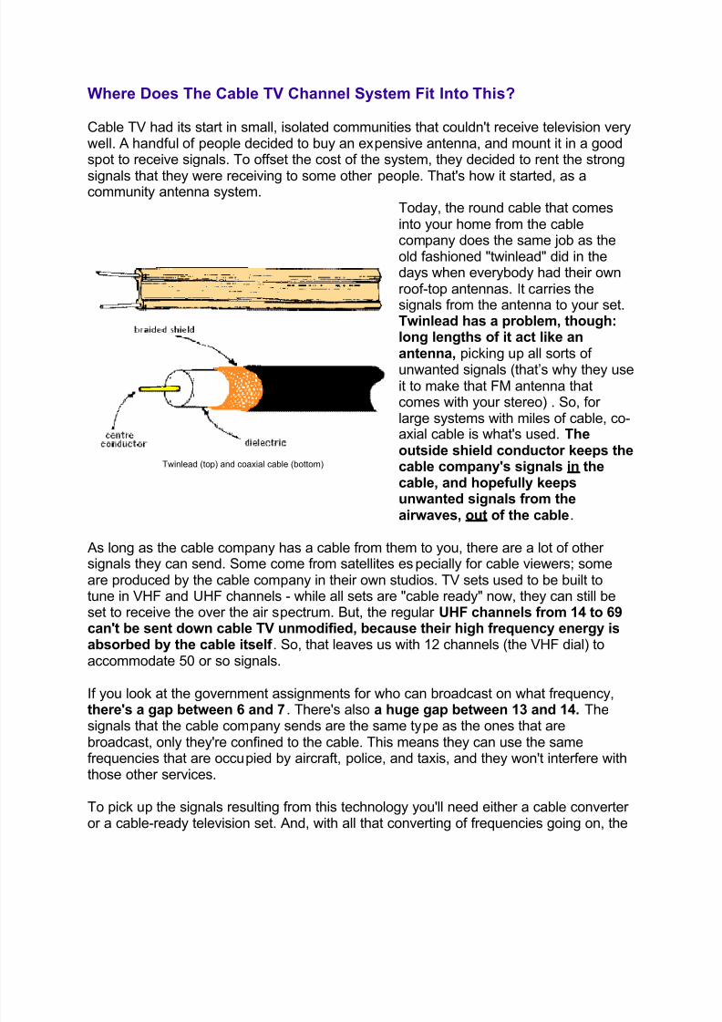
Twinlead (top) and coaxial cable (bottom)
Today, the round cable that comesinto your home from the cablecompany does the same job as theold fashioned "twinlead" did in thedays when everybody had their ownroof-top antennas. It carries thesignals from the antenna to your set.Twinlead has a problem, though:long lengths of it act like an
antenna, picking up all sorts of unwanted signals (that¶s why they useit to make that FM antenna thatcomes with your stereo) . So, for large systems with miles of cable, co-axial cable is what's used. Theoutside shield conductor keeps thecable company's signals in thecable, and hopefully keepsunwanted signals from theairwaves, out of the cable.
As long as the cable company has a cable from them to you, there are a lot of other signals they can send. Some come from satellites especially for cable viewers; someare produced by the cable company in their own studios. TV sets used to be built totune in VHF and UHF channels - while all sets are "cable ready" now, they can still beset to receive the over the air spectrum. But, the regular UHF channels from 14 to 69can't be sent down cable TV unmodified, because their high frequency energy isabsorbed by the cable itself . So, that leaves us with 12 channels (the VHF dial) toaccommodate 50 or so signals.
If you look at the government assignments for who can broadcast on what frequency,
there's a gap between 6 and 7. There's also a huge gap between 13 and 14. Thesignals that the cable company sends are the same type as the ones that arebroadcast, only they're confined to the cable. This means they can use the samefrequencies that are occupied by aircraft, police, and taxis, and they won't interfere withthose other services.
To pick up the signals resulting from this technology you'll need either a cable converter or a cable-ready television set. And, with all that converting of frequencies going on, the
8/6/2019 One Night I Walked Home Very Late and Fell Asleep in Somebody
http://slidepdf.com/reader/full/one-night-i-walked-home-very-late-and-fell-asleep-in-somebody 21/34
cable company gives you a chart.
Here's what's happening. The numbers 2 to 13 on your converter are real channels 2through 13. The cable company probably has converted some UHF channels in your
area to these, and chances are that the others are on the wrong channels, but they
really occupy channels 2 through 13. Channels 14 and up aren't what they seem - 14 to22 are the hidden 9 channels between the real 6 and 7, and 23 to 64 are a bunchfrom between real 13 and 14.
For those of you with 100 channel cable-ready televisions, you also have channels 65through 94, located in, yes, UHF areas 14 through 43. But wait a minute, we saidthat UHF channels can't be transmitted down the cable. Well, they can, but theybecome increasingly noisy as you go up the band. This is why, up until lately, cablecompanies weren't using these frequencies. Channels 95 through 99 are located tocover completely, and go just above, the FM radio band. That's why there's nothing onthose channels, either.
Try This At Home!
Tune your cable ready TV set to some upper channels. Notice how they get noisy, thehigher you go. Now, tune way up there - into the 80s and 90s. See any other channelsthe cable company is using that you don¶t know about? Sometimes, on Rogers, you seea graphic display called a "spectrum analyzer" that looks at the relative levels of all thechannels in the system!
Don't Touch That Dial: Digital Cable, Telcos, MMDS, LMCS, DBS
Over-the-air terrestrial transmission and standard analog cable TV no longer have amonopoly on the way to get television signals into your home. There are several other systems. Keep a watch for:
Digital Cable TV
Brought to you by your local cable company, it¶s a digital multi-channel version of whatwe know in the analog world, using the same cable, but getting around that coaxialcable frequency absor ption problem by encoding the television channels digitally. Itrequires a set-top box to decode the digital signals back into analog NTSC for you toenjoy.
Video By Telephone
Your local telephone company, for years, was working overtime to perfect a system thatwill bring video to your place via phone lines (plain old telephone service, or POTS), or a modification thereof. Not much news lately, but you never know. Stay tuned.
8/6/2019 One Night I Walked Home Very Late and Fell Asleep in Somebody
http://slidepdf.com/reader/full/one-night-i-walked-home-very-late-and-fell-asleep-in-somebody 22/34
Multichannel Multipoint Distribution Systems (MMDS)
On August 6, 1997, Teleglobe Inc. won a license to begin a service called Look TV inthe Toronto area. It¶s based on a system called MMDS. It works in the 2.5 to 2.686 GHzrange and can do a line of sight transmission of 40 to 50 kilometres. The main antenna
is on the CN Tower, but there are some booster/repeater towers around town, so if youcan see any of them, you can subscribe to MMDS distribution. The repeaters increasethe coverage by receiving the main signal and retransmitting it further afield. MMDSuses a 30 cm square flat antenna, and no cables. The MMDS system is comparablypriced to regular cable TV subscription rates, after an installation fee. Look TV now hasservices in Southern Ontario, Ottawa, Montreal, Trois-Rivieres, and Quebec City. InManitoba, a similar system called SkyCable already exists and works on the sameprinciples.
Direct Broadcast Satellite (DBS)
Various pizza-sized dish "direct to home" satellite reception alternatives, that have gotoff to a slow start in Canada (but are picking up steam quickly) and have done well inthe United States. More on these later in this chapter.
Wireless Mics, IFBs, Headsets and Interference
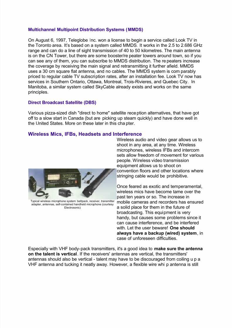
Typical wireless microphone system: beltpack, receiver, transmitter adapter, antennas, self-contained handheld microphone (courtesy
Electrosonic)
Wireless audio and video gear allows us toshoot in any area, at any time. Wirelessmicrophones, wireless IFBs and intercomsets allow freedom of movement for variouspeople. Wireless video transmissionequipment allows us to shoot on
convention floors and other locations wherestringing cable would be prohibitive.
Once feared as exotic and temperamental,wireless mics have become tame over thepast ten years or so. The increase inmobile cameras and recorders has ensureda solid place for them in the future of broadcasting. This equipment is veryhandy, but causes some problems since itcan cause interference, and be interfered
with. Let the user beware! One shouldalways have a backup (wired) system, incase of unforeseen difficulties.
Especially with VHF body-pack transmitters, it's a good idea to make sure the antennaon the talent is vertical. If the receivers' antennas are vertical, the transmitters'antennas should also be vertical - talent may have to be discouraged from coiling up aVHF antenna and tucking it neatly away. However, a flexible wire whip antenna is still
8/6/2019 One Night I Walked Home Very Late and Fell Asleep in Somebody
http://slidepdf.com/reader/full/one-night-i-walked-home-very-late-and-fell-asleep-in-somebody 23/34
preferred to a more rigid "rubber duck" antenna, since the human body is largelycomposed of water and salt (conductive), and it tends to detune the stiffer type of antenna.
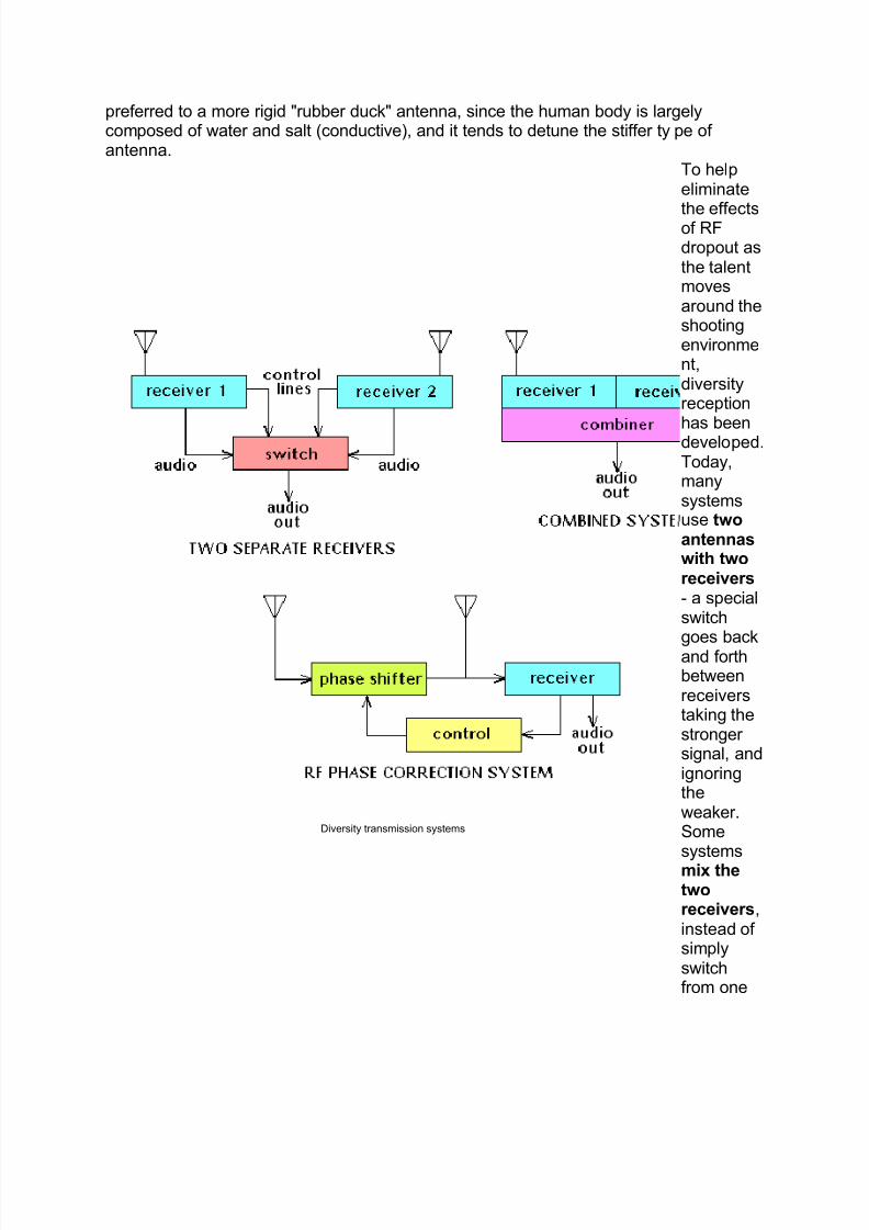
Diversity transmission systems
To help eliminate
the effectsof RFdropout asthe talentmovesaround theshootingenvironment,diversityreception
has beendeveloped.Today,manysystemsuse twoantennaswith tworeceivers - a specialswitchgoes backand forthbetweenreceiverstaking thestronger signal, andignoringtheweaker.Somesystemsmix thetworeceivers,instead of simplyswitchfrom one
8/6/2019 One Night I Walked Home Very Late and Fell Asleep in Somebody
http://slidepdf.com/reader/full/one-night-i-walked-home-very-late-and-fell-asleep-in-somebody 24/34
to another. Another systeminvolveschecking
thereceivedRF phasebetweentwoantennas- thephase of thesecondone is
constantly adjustedtocomplement thesignalfrom thefirst. This
unit needsonly onereceiver and oneaudiooutput.
Wirelessaudio gear operateson variousVHF andUHFfrequencies betweentelevisionchannel 7and 13.Theseunits arealso usedon location
8/6/2019 One Night I Walked Home Very Late and Fell Asleep in Somebody
http://slidepdf.com/reader/full/one-night-i-walked-home-very-late-and-fell-asleep-in-somebody 25/34
shoots tofree talentof their audioumbilical
cord.
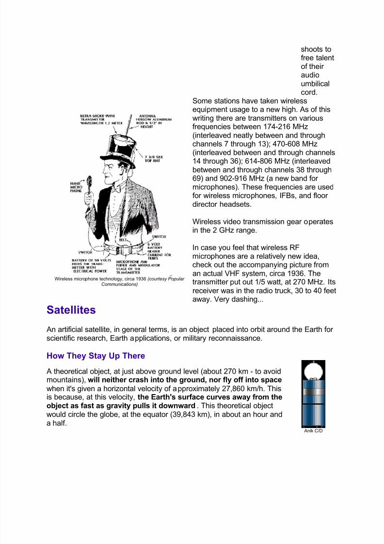
Wireless microphone technology, circa 1936 ( courtesy Popular
Communications)
Some stations have taken wirelessequipment usage to a new high. As of thiswriting there are transmitters on variousfrequencies between 174-216 MHz(interleaved neatly between and throughchannels 7 through 13); 470-608 MHz(interleaved between and through channels14 through 36); 614-806 MHz (interleavedbetween and through channels 38 through69) and 902-916 MHz (a new band for
microphones). These frequencies are usedfor wireless microphones, IFBs, and floor director headsets.
Wireless video transmission gear operatesin the 2 GHz range.
In case you feel that wireless RFmicrophones are a relatively new idea,check out the accompanying picture froman actual VHF system, circa 1936. The
transmitter p
ut out 1/5 watt, at 270 MHz.I
tsreceiver was in the radio truck, 30 to 40 feetaway. Very dashing...
Satellites
An artificial satellite, in general terms, is an object placed into orbit around the Earth for scientific research, Earth applications, or military reconnaissance.
How They Stay Up There
A theoretical object, at just above ground level (about 270 km - to avoid
mountains), will neither crash into the ground, nor fly off into space when it's given a horizontal velocity of approximately 27,860 km/h. Thisis because, at this velocity, the Earth's surface curves away from theobject as fast as gravity pulls it downward. This theoretical objectwould circle the globe, at the equator (39,843 km), in about an hour anda half.
Anik C/D
8/6/2019 One Night I Walked Home Very Late and Fell Asleep in Somebody
http://slidepdf.com/reader/full/one-night-i-walked-home-very-late-and-fell-asleep-in-somebody 26/34
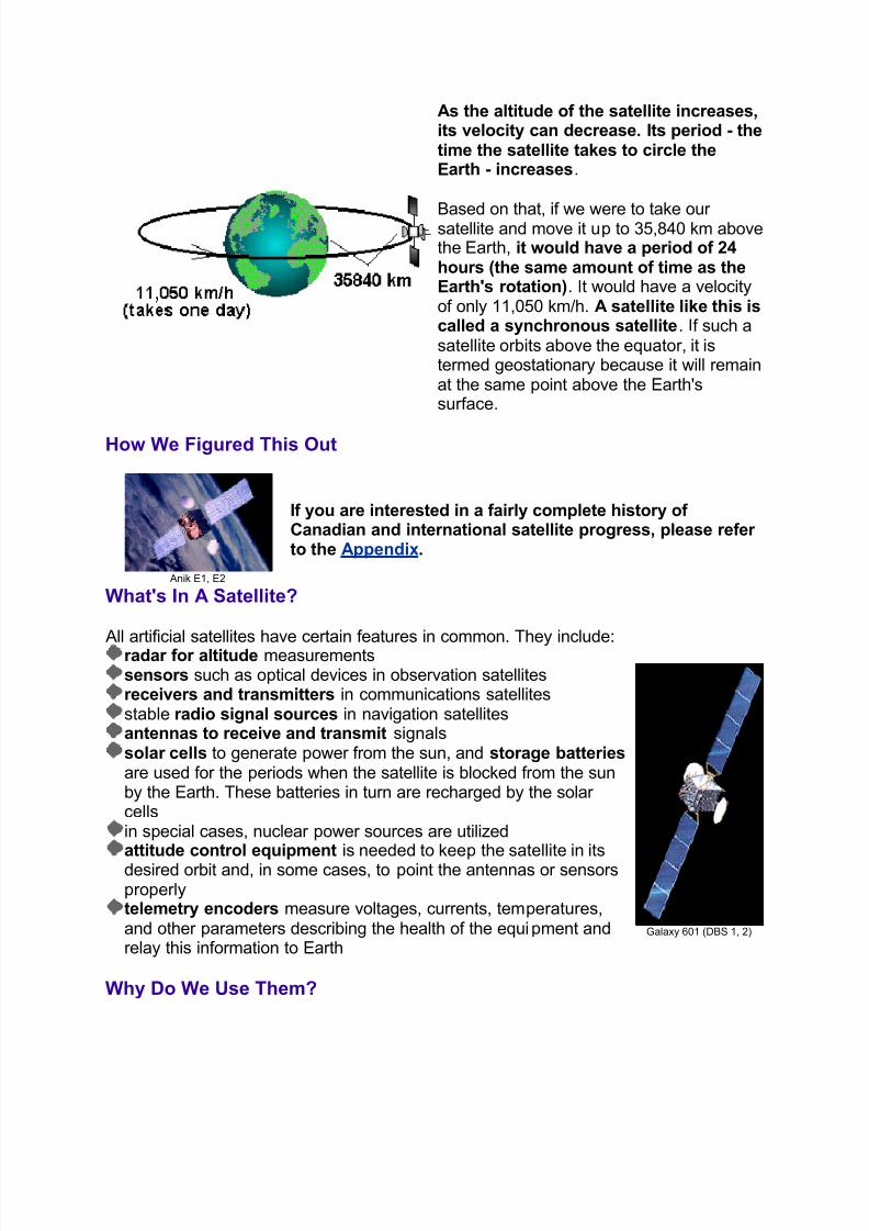
As the altitude of the satellite increases,its velocity can decrease. Its period - thetime the satellite takes to circle theEarth - increases.
Based on that, if we were to take our satellite and move it up to 35,840 km abovethe Earth, it would have a period of 24hours (the same amount of time as theEarth's rotation). It would have a velocityof only 11,050 km/h. A satellite like this iscalled a synchronous satellite. If such asatellite orbits above the equator, it istermed geostationary because it will remainat the same point above the Earth'ssurface.
How We Figured This Out
Anik E1, E2
If you are interested in a fairly complete history of Canadian and international satellite progress, please refer to the Appendix.
What's In A Satellite?
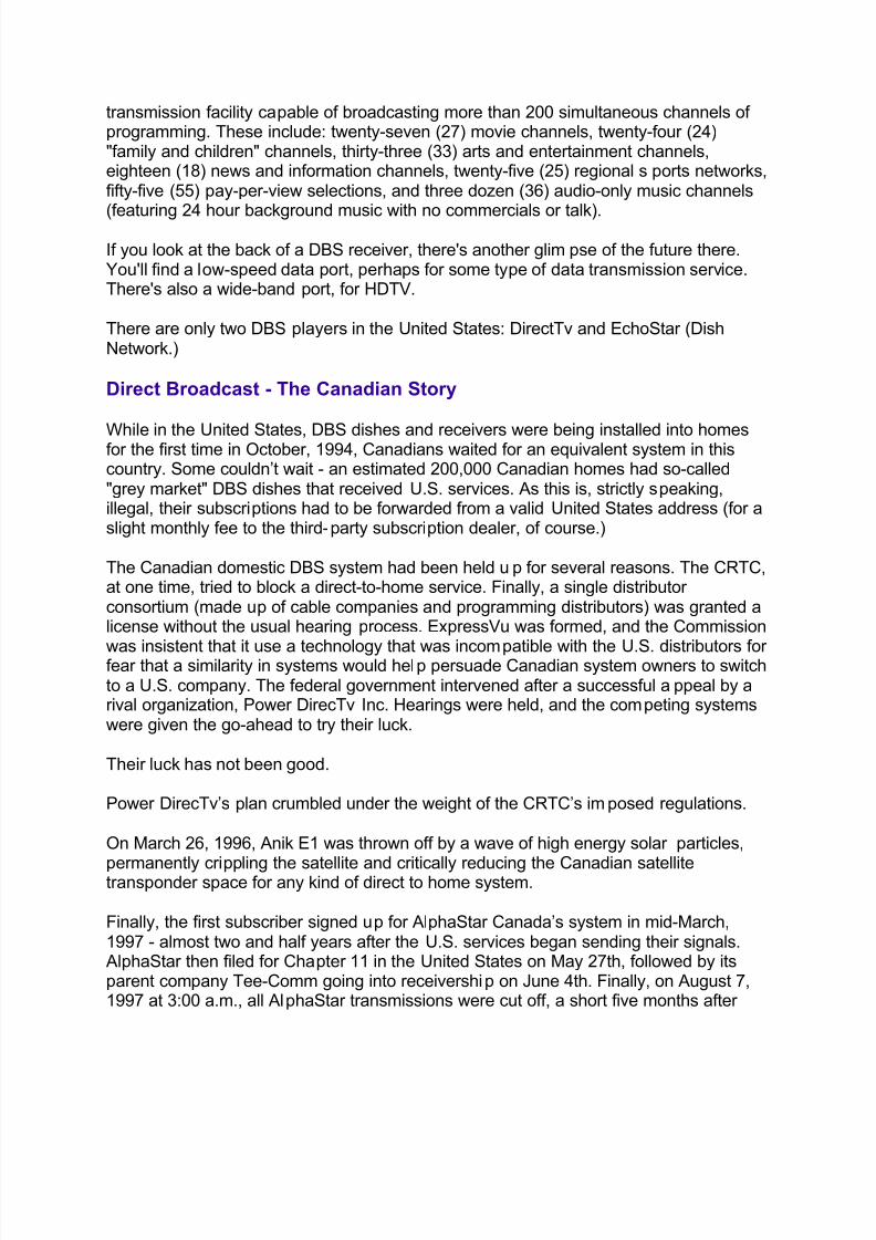
All artificial satellites have certain features in common. They include:radar for altitude measurements
sensors such as optical devices in observation satellites receivers and transmitters in communications satellites
stable radio signal sources in navigation satellites antennas to receive and transmit signals
solar cells to generate power from the sun, and storage batteries are used for the periods when the satellite is blocked from the sunby the Earth. These batteries in turn are recharged by the solar cells
in special cases, nuclear power sources are utilized attitude control equipment is needed to keep the satellite in itsdesired orbit and, in some cases, to point the antennas or sensorsproperly telemetry encoders measure voltages, currents, temperatures,and other parameters describing the health of the equipment andrelay this information to Earth
Galaxy 601 (DBS 1, 2)
Why Do We Use Them?
8/6/2019 One Night I Walked Home Very Late and Fell Asleep in Somebody
http://slidepdf.com/reader/full/one-night-i-walked-home-very-late-and-fell-asleep-in-somebody 27/34
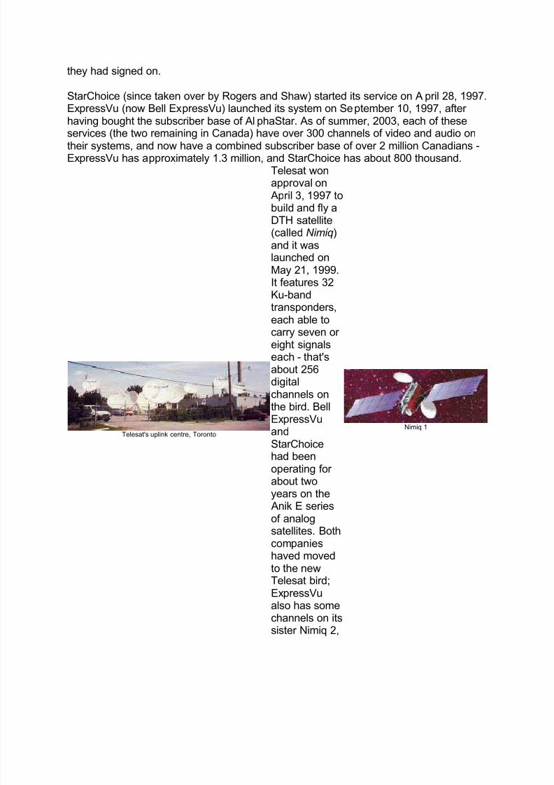
Typical microwave
tower
Most long-distance radio communication across land is sent via microwaverelay towers. These towers, 30 to 60 metres high, are typically spaced 30to 50 km apart, and about 100 of them are needed to cross the country.Thus microwave relay towers are impractical for transoceanic
communications.
The satellite serves as a sort of tall microwave tower to permit directtransmission between stations. But, unlike a microwave link or a cable,it can interconnect any number of stations that are included withinthe antenna beams of the satellite rather than simply the two ends of the microwave link. The use of a satellite repeater was first proposed by
Arthur C. Clarke in the October 1945 issue of W ireless W orld .
Who's Up There?
For a complete explanation of the various kinds of satellites, their altitudes anduses, please refer to the Appendix.
Okay Then, Can You At Least Tell Me What Geosynchronous SatellitesAre Available in North America? Sure. Click on the picture for a large detailed view of all satellites we cansee from North America. The picture is mine (and is copyrighted, so if youuse it, give me and this website credit), but the raw data is from LyngSat(www.lyngsat.com) and is accurate as of August, 2003. But the satellitepicture is changing all the time, so this diagram is subject to change
without notice.
DBS
Direct Broadcast Satellite...the Death Star...
You heard all about it through the 1990s. Thelaunch of Hughes Galaxy 601 (commonlyknown in the industry as DBS-1) in December of 1993 signalled the beginning of a new era inentertainment distribution. This service now
beams more than 225 channels of audio andvideo programming to 18-inch satellite dishesinstalled in homes across the 48 contiguousUnited States (and a few Canadian provinces,as well.)
DirecTv, Castle Rock, Colorado
Hughes' DirecTv's broadcast centre is in Castle Rock, Colorado (about 30 miles southof Denver) and uses the DBS-1 and DBS-2 satellites. It was the first fully serial digital
8/6/2019 One Night I Walked Home Very Late and Fell Asleep in Somebody
http://slidepdf.com/reader/full/one-night-i-walked-home-very-late-and-fell-asleep-in-somebody 28/34
transmission facility capable of broadcasting more than 200 simultaneous channels of programming. These include: twenty-seven (27) movie channels, twenty-four (24)"family and children" channels, thirty-three (33) arts and entertainment channels,eighteen (18) news and information channels, twenty-five (25) regional sports networks,fifty-five (55) pay-per-view selections, and three dozen (36) audio-only music channels
(featuring 24 hour background music with no commercials or talk).
If you look at the back of a DBS receiver, there's another glimpse of the future there.You'll find a low-speed data port, perhaps for some type of data transmission service.There's also a wide-band port, for HDTV.
There are only two DBS players in the United States: DirectTv and EchoStar (DishNetwork.)
Direct Broadcast - The Canadian Story
While in the United States, DBS dishes and receivers were being installed into homesfor the first time in October, 1994, Canadians waited for an equivalent system in thiscountry. Some couldn¶t wait - an estimated 200,000 Canadian homes had so-called"grey market" DBS dishes that received U.S. services. As this is, strictly speaking,illegal, their subscriptions had to be forwarded from a valid United States address (for aslight monthly fee to the third-party subscription dealer, of course.)
The Canadian domestic DBS system had been held up for several reasons. The CRTC,at one time, tried to block a direct-to-home service. Finally, a single distributor consortium (made up of cable companies and programming distributors) was granted alicense without the usual hearing process. ExpressVu was formed, and the Commission
was insistent that it use a technology that was incompatible with the U.S. distributors for fear that a similarity in systems would help persuade Canadian system owners to switchto a U.S. company. The federal government intervened after a successful appeal by arival organization, Power DirecTv Inc. Hearings were held, and the competing systemswere given the go-ahead to try their luck.
Their luck has not been good.
Power DirecTv¶s plan crumbled under the weight of the CRTC¶s imposed regulations.
On March 26, 1996, Anik E1 was thrown off by a wave of high energy solar particles,
permanently crippling the satellite and critically reducing the Canadian satellitetransponder space for any kind of direct to home system.
Finally, the first subscriber signed up for AlphaStar Canada¶s system in mid-March,1997 - almost two and half years after the U.S. services began sending their signals.
AlphaStar then filed for Chapter 11 in the United States on May 27th, followed by itsparent company Tee-Comm going into receivership on June 4th. Finally, on August 7,1997 at 3:00 a.m., all AlphaStar transmissions were cut off, a short five months after
8/6/2019 One Night I Walked Home Very Late and Fell Asleep in Somebody
http://slidepdf.com/reader/full/one-night-i-walked-home-very-late-and-fell-asleep-in-somebody 29/34
they had signed on.
StarChoice (since taken over by Rogers and Shaw) started its service on April 28, 1997.ExpressVu (now Bell ExpressVu) launched its system on September 10, 1997, after having bought the subscriber base of AlphaStar. As of summer, 2003, each of these
services (the two remaining in Canada) have over 300 channels of video and audio ontheir systems, and now have a combined subscriber base of over 2 million Canadians -ExpressVu has approximately 1.3 million, and StarChoice has about 800 thousand.
Telesat's uplink centre, Toronto
Telesat wonapproval on
April 3, 1997 tobuild and fly aDTH satellite(called N imiq)and it waslaunched on
May 21, 1999.It features 32Ku-bandtransponders,each able tocarry seven or eight signalseach - that'sabout 256digitalchannels onthe bird. BellExpressVuandStarChoicehad beenoperating for about twoyears on the
Anik E seriesof analogsatellites. Bothcompanieshaved movedto the newTelesat bird;ExpressVualso has somechannels on itssister Nimiq 2,
Nimiq 1
8/6/2019 One Night I Walked Home Very Late and Fell Asleep in Somebody
http://slidepdf.com/reader/full/one-night-i-walked-home-very-late-and-fell-asleep-in-somebody 30/34
launchedDecember 30,2002.
World Television Standards
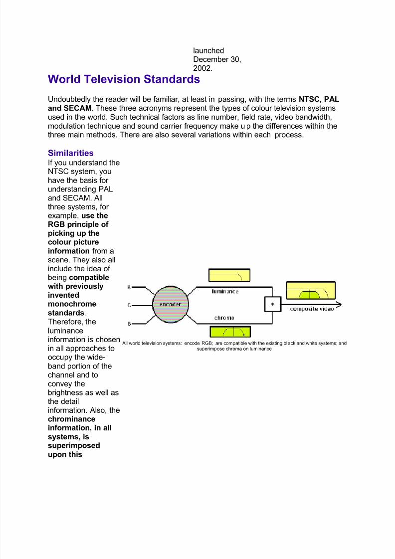
Undoubtedly the reader will be familiar, at least in passing, with the terms NTSC, PALand SECAM. These three acronyms represent the types of colour television systemsused in the world. Such technical factors as line number, field rate, video bandwidth,modulation technique and sound carrier frequency make up the differences within thethree main methods. There are also several variations within each process.
Similarities If you understand theNTSC system, youhave the basis for understanding PAL
and SECAM. Allthree systems, for example, use theRGB principle of picking up thecolour pictureinformation from ascene. They also allinclude the idea of being compatiblewith previously
inventedmonochromestandards.Therefore, theluminanceinformation is chosenin all approaches tooccupy the wide-band portion of thechannel and toconvey the
brightness as well asthe detailinformation. Also, thechrominanceinformation, in allsystems, issuperimposedupon this
All world television systems: encode RGB; are compatible with the existing black and white systems; andsuperimpose chroma on luminance
8/6/2019 One Night I Walked Home Very Late and Fell Asleep in Somebody
http://slidepdf.com/reader/full/one-night-i-walked-home-very-late-and-fell-asleep-in-somebody 31/34
luminance signal.
For a complete analysis of the encoding systems of the three major televisionstandards, and an understanding of the various scanning rates used inconjunction with these systems, please refer to the Appendix.
Standards Converters
The fact that there are at least eight major TV standards in the world today is a barrier to the simple interchange of foreign programs and sporting events. Fortunately, thesedifficulties can be solved using standards converters.
Standards conversion is the process of changing the line and/or field ratestructure of the TV signal. Ideally, this should be done with a minimum of what'scalled "judder", which is a motion artifact wherein smooth motion is portrayed in anirregular, shuddering way. Standards conversion is best accomplished in the digital
domain. The advantage of digital processing revolves around the ability to use digitalprocessing of multiple fields of video, along with an ever-increasing availability of computing power, allowing more complex conversion formulas. Converters analyzeincoming video fields at one sample rate and create intermediate fields throughinterpolation, at the sample rate of the output standard. It's the job of motioncompensation formulas to compute where an object will be in the next field. If this isdone successfully, the output displays motion smoothly, with a minimum of artifacts.
Sports programming is frequently used to test and demonstrate standards converters.Interestingly, our own sport of hockey features fast pans and the small, fast puck,as well as high contrast, stark images that will reveal any judder .
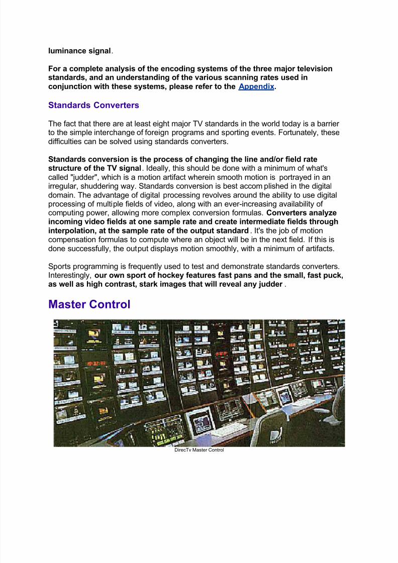
Master Control
DirecTv Master Control
8/6/2019 One Night I Walked Home Very Late and Fell Asleep in Somebody
http://slidepdf.com/reader/full/one-night-i-walked-home-very-late-and-fell-asleep-in-somebody 32/34
When all of the diverse elements of the daily program schedule come together, therehas to be some way of integrating them in a connected way. That is where master control comes in. Master control operators (and their equipment) are responsible for the final output and look of the station. Their varied tasks include:
rolling in various pre-recorded programming, either on videotape or film,taking live shows (such as news programming and flashes) at the proper time,inserting at the proper time appropriate bumpers and commercial breaks, loggingthose commercials,adding station IDs and audio carts when required,ensuring that all programming is integrated into the day as per the directions of the
programming and traffic departments,and making sure that the transmission of the station is always flawless.
It is a sometimes hectic series of proceedings, involving minute-by-minute scrutiny of programs, cue sheets, and technical quality of all material. Paper logs of all
commercial and promotional content have to be accurate, as required by the CRTC.There are also videotape logs to be maintained, which are kept in a library containingevery minute of broadcasting for the last two months.
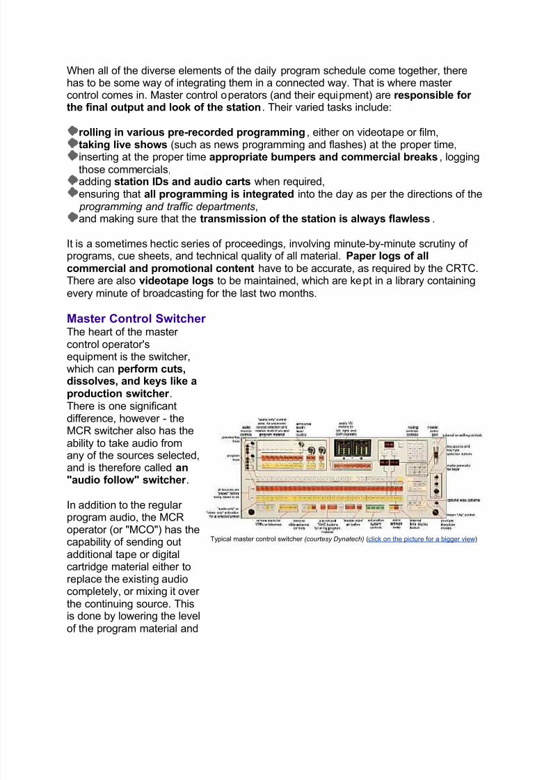
Master Control Switcher The heart of the master control operator'sequipment is the switcher,which can perform cuts,dissolves, and keys like aproduction switcher .
There is one significantdifference, however - theMCR switcher also has theability to take audio fromany of the sources selected,and is therefore called an"audio follow" switcher .
In addition to the regular program audio, the MCRoperator (or "MCO") has the
capability of sending outadditional tape or digitalcartridge material either toreplace the existing audiocompletely, or mixing it over the continuing source. Thisis done by lowering the levelof the program material and
Typical master control switcher ( courtesy Dynatech) (click on the picture for a bigger view)
8/6/2019 One Night I Walked Home Very Late and Fell Asleep in Somebody
http://slidepdf.com/reader/full/one-night-i-walked-home-very-late-and-fell-asleep-in-somebody 33/34
is called "voice over" mode.
The keyer on the switcher isgenerally used tosuperimpose station
identification informationover program material, or other statistics such as thetime of day. With all of this information and technical detail to watch over, master control operationsare beginning to computerize. The computer remembers and activates transitionssequences. It also cues, rolls, and stops film projectors and VTRs, and calls upany number of slides from the stillstore system.
The development of MCR switchers is going in two directions. One can have theswitcher perform more and more visual tricks. Or, it can be kept simple enough so that
the operator does not have to climb all over it to reach everything, or take a computer course to use it.
Things To Think About
Our television transmission system uses radio waves, travelling
at the speed of light. Radio waves can be modulated in various
ways, and we use both AM and FM in television transmission.
For best results, antennas should be of a certain length and
polarity, and there is a tried and true process for modulating
and demodulating transmissions. The television channel has within it video, and multiple channels of audio.
The electromagnetic spectrum has been carefully carved up by the
power that be so that everybody gets to use what they need and
not interfere with one another. The dissection is intricate, and
you should be familiar with some of the fundamental slices.
Every year, somebody comes up with another use for the
electromagnetic spectrum - different ways of transmitting
signals to the home, wireless mics, and so on.
Satellites are 20th-century wonders. They have some basiccomponents that make them work well, and more capacity is now
available with digital compression.
There are three major world television colour standards, and
even though they differ widely, they have some commonality
between them. To go from one format to another, we use scans
conversions.

8/6/2019 One Night I Walked Home Very Late and Fell Asleep in Somebody
http://slidepdf.com/reader/full/one-night-i-walked-home-very-late-and-fell-asleep-in-somebody 34/34
Master control is the place we¶ve all been waiting for. Without
it, all of our hard work never makes it to air. Be conscious of
the importance of this facility, and some of the things this
environment does to keep us in the skies.