Embed Size (px)
Citation preview
Third Quarter 2017 | Volume 36 | Number 3
A Journal of the Thermoforming Division of SPE
IN THIS ISSUE:
Heat-Stable UV Inks
Managing Wall Thickness Distribution
2017 SPE Thermoforming Division Scholarship Winners
One Good Turn Deserves Another

2 SPE Thermoforming Quarterly
SPE Thermoforming Quarterly 3
n DepartmentsChairman’s Corner | 4
New Members | 5
Thermoforming in the News | 6-7
n FeaturesBringing 2D Inkjet into 3D Forming Applications | 14-19
Hybrid Thermoforming | 20-25
A Holistic Approach for Sheet Fed Tooling Development | 26-29
Managing Wall Thickness Distribution | 30-37
How Important is the Volumetric Absorption Concept? Part 2: Model Building | 38-42
n In This Issue2017 SPE Thermoforming Division Scholarship Winners | 8
Innovation Briefs: The Marbach Turner Concept | 44-45
Innovation Briefs: Cleantivity® from Illig | 46-47
A JOURNAL PUBLISHED EACH CALENDAR QUARTER BY THE THERMOFORMING DIVISION
OF THE SOCIETY OF PLASTICS ENGINEERS
www.thermoformingdivision.comEditor
Conor Carlin(617) 771-3321
SponsorshipsLesley Kyle
(914) [email protected]
Conference CoordinatorLesley Kyle
(914) [email protected]
SPE Thermoforming Quarterly® is published four times annually as an informational and educational bulletin to the members of the Society of Plastics Engineers, Thermoforming Division, and the thermoforming industry. The name, “SPE Thermoforming Quarterly®” and its logotype, are registered trademarks of the Thermoforming Division of the Society of Plastics Engineers, Inc. No part of this publication may be reproduced in any form or by any means without prior written permission of the publisher, copyright holder. Opinions of the authors are their own, and the publishers cannot be held responsible for opinions or representations of the authors. Printed in the U.S.A.
SPE Thermoforming Quarterly® is reg-istered in the U.S. Patent and Trademark Office (Registration no. 2,229,747). x
Third Quarter 2017 | Volume 36 | Number 3
Cover image courtesy of Marbach Werkzeugbau GmbH.
4 SPE Thermoforming Quarterly
Chairman’s Corner
Orlando, Here We Come!
It’s almost time for the big event in Orlando! The program
is complete, the sponsors are lined up and the speakers
are rehearsing their presentations. This year’s conference
promises to be unique in many ways, with a brand-new
RC car race, lively panel discussions, and a “War Room”
event where design and thermoforming collide. Of course,
we’re also happy to organize proven classic events like our
Casino Night and packed exhibit floor.
This issue of TQ is again loaded with original content,
one of the primary benefits of belonging to our thriving
division. Dr. Throne continues to push the boundaries of
thermoforming science with the second installment of
his work on heat transfer models (see p. 38). Speaking of
boundaries, Jerry Dees introduces us to a novel concept
called “Hybrid Thermoforming” that should get people
talking in the halls (p. 20). We also feature new “Innovation
Briefs” from Europe as toolmaker Marbach launches a new
“Turner Concept”, a thermoformed container which can be
closed and re-closed with a thermoformed lid. Hailing from
the same city in Germany, the folks at Illig have coined
a new word that combines cleanliness and productivity:
“Cleantivity”.
In other news, we continue to see M&A activity in our
industry with several new large purchases in the thin-gauge
packaging sector. While the dollars continue to flow at the
board level, several commentators are raising some tough
questions about skills and wages. Monica Jacobs of KLA
(p.10) addresses the question of whether businesses are
doing enough to attract top talent and remain competitive.
Our panel discussion at the conference will also discuss
what it means to “hunt unicorns” in today’s market.
SPE is 75 this year and the august society is hosting a major
bash in Detroit, MI (August 24). “The Future Is Plastics”
will recognize innovation in manufacturing as well as the
accomplishments of rising young professionals. This event
will feature special presentations, a reception to toast
SPE’s 75th anniversary and a chance to meet many veteran
and young leaders in the plastics industry. The division’s
councilor and some other members will be there, so we
can be sure of a full report in the next issue.
For now, let’s enjoy the remainder of the summer. I know
I plan to recharge my batteries in advance of Orlando,
because this is going to be a productive and fun couple of
days. See you soon! |
Bret Joslyn
SPE Thermoforming Quarterly 5
New Members
Clemente AvilaStruktolZapopan, Jalisco Mexico
Patricia Champlin Ovation Polymers Akron, OH
Tracey Crews-Hammond Hilton Displays Greenville, SC Bruce FakooryVF Packaging Ltd. San Juan Trinidad and Tobago
Dean FakooryVF Packaging Ltd. San Juan Trinidad and Tobago
David ForlandNike Inc. Beaverton, OR
Jim Henry Diversified Mold & CastingsQuincy, IL Erich Kaintz SAY Plastics, Inc. McSherrystown, PA Rex Kanu Noblesville, IN
Scott Kapelanski Delta Faucet Co. Lapeer, MI
Travis KiefferPlastics Unlimited Inc. Preston, IA
Marek NikiforovGN EuropeJihlava, Czech Republic
Michel PyCGP EuropeBussy Saint Georges France
Joseph Schlatter MP Components Byron Center, MI
Matthew ShuertShuert Technologies Sterling Heights, MI Maxwell Sullivan CDF CorpPlymouth, MA
Ryan TroianoGreiner Packaging USA Lake Ariel, PA Matt Weber Advanced Extrusion Rogers, MN
Submission Guidelines• We are a technical journal. We strive
for objective, technical articles that help
advance our readers’ understanding
of thermoforming (process, tooling,
machinery, ancillary services); in other
words, no commercials.
• Article length:1,000 - 2,000 words.
Look to past articles for guidance.
• Format: .doc or .docx Artwork: hi-res
images are encouraged (300 dpi)
with appropriate credits.
Send all submissions to Conor Carlin,
Editor, at [email protected]
Have an ideafor an
article?
6 SPE Thermoforming Quarterly
Thermoforming In The News
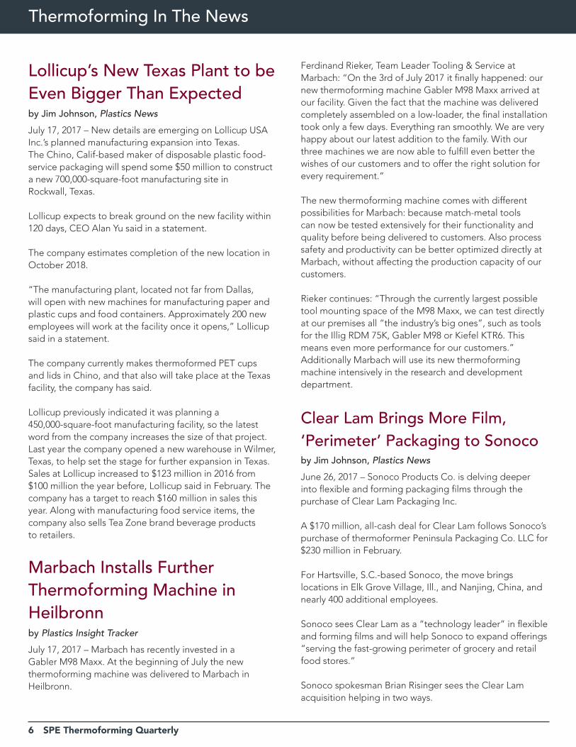
Lollicup’s New Texas Plant to be Even Bigger Than Expectedby Jim Johnson, Plastics News
July 17, 2017 – New details are emerging on Lollicup USA Inc.’s planned manufacturing expansion into Texas.The Chino, Calif-based maker of disposable plastic food-service packaging will spend some $50 million to construct a new 700,000-square-foot manufacturing site in Rockwall, Texas.
Lollicup expects to break ground on the new facility within 120 days, CEO Alan Yu said in a statement.
The company estimates completion of the new location in October 2018.
“The manufacturing plant, located not far from Dallas, will open with new machines for manufacturing paper and plastic cups and food containers. Approximately 200 new employees will work at the facility once it opens,” Lollicup said in a statement.
The company currently makes thermoformed PET cups and lids in Chino, and that also will take place at the Texas facility, the company has said.
Lollicup previously indicated it was planning a 450,000-square-foot manufacturing facility, so the latest word from the company increases the size of that project.Last year the company opened a new warehouse in Wilmer, Texas, to help set the stage for further expansion in Texas.Sales at Lollicup increased to $123 million in 2016 from $100 million the year before, Lollicup said in February. The company has a target to reach $160 million in sales this year. Along with manufacturing food service items, the company also sells Tea Zone brand beverage products to retailers.
Marbach Installs Further Thermoforming Machine in Heilbronnby Plastics Insight Tracker
July 17, 2017 – Marbach has recently invested in a Gabler M98 Maxx. At the beginning of July the new thermoforming machine was delivered to Marbach in Heilbronn.
Ferdinand Rieker, Team Leader Tooling & Service at Marbach: “On the 3rd of July 2017 it finally happened: our new thermoforming machine Gabler M98 Maxx arrived at our facility. Given the fact that the machine was delivered completely assembled on a low-loader, the final installation took only a few days. Everything ran smoothly. We are very happy about our latest addition to the family. With our three machines we are now able to fulfill even better the wishes of our customers and to offer the right solution for every requirement.”
The new thermoforming machine comes with different possibilities for Marbach: because match-metal tools can now be tested extensively for their functionality and quality before being delivered to customers. Also process safety and productivity can be better optimized directly at Marbach, without affecting the production capacity of our customers.
Rieker continues: “Through the currently largest possible tool mounting space of the M98 Maxx, we can test directly at our premises all “the industry’s big ones”, such as tools for the Illig RDM 75K, Gabler M98 or Kiefel KTR6. This means even more performance for our customers.”Additionally Marbach will use its new thermoforming machine intensively in the research and development department.
Clear Lam Brings More Film, ‘Perimeter’ Packaging to Sonocoby Jim Johnson, Plastics News
June 26, 2017 – Sonoco Products Co. is delving deeper into flexible and forming packaging films through the purchase of Clear Lam Packaging Inc.
A $170 million, all-cash deal for Clear Lam follows Sonoco’s purchase of thermoformer Peninsula Packaging Co. LLC for $230 million in February.
For Hartsville, S.C.-based Sonoco, the move brings locations in Elk Grove Village, Ill., and Nanjing, China, and nearly 400 additional employees.
Sonoco sees Clear Lam as a “technology leader” in flexible and forming films and will help Sonoco to expand offerings “serving the fast-growing perimeter of grocery and retail food stores.”
Sonoco spokesman Brian Risinger sees the Clear Lam acquisition helping in two ways.
SPE Thermoforming Quarterly 7
“The acquisition of Clear Lam adds capabilities for us, the ability to internalize this capability from a manufacturing standpoint of more complex films and internalizing those costs,” he said.
Sonoco does make film on what Risinger described as a limited basis, but Clear Lam brings “complex, multilayer” production. “And that’s not a capability we had.”
Sonoco’s current film-making capabilities center around its thermoforming business and includes multilayer and barrier capabilities, but not to the extent that Clear Lam will bring.
“The second thing is just the nature of their portfolio. We acquired Peninsula back in the spring and we are really focused on getting more into the perimeter of the store. Much of Clear Lam’s portfolio is also in fresh perishables,” Risinger said.
“I would say those are the two driving factors. There’s a technical capability and then there’s a portfolio that’s a good complement for us that, again, allows us to expand our footprint at retail,” he said.
“We’ve been pretty transparent and clear about making strategic acquisitions that add a capability that we don’t have and then, perhaps, open up a market for us that we’re not operating in.
“At a macro level, we are trying to pivot our business and have a greater share of it be in consumer packaging. And then within the consumer packaging segment ... the perimeter of the store, that’s where the growth is. A large part of our portfolio really had been in the center, in more processed foods,” Risinger said.
With two deals already under its belt this year, Sonoco expects to continue seeking out expansion opportunities in this market segment.
“We’re actively looking, especially in flexibles and in rigid plastics, for opportunities to expand our portfolio into more fresh [foods],” Risinger said.
Sales at Clear Lam are expected to be about $140 million this year, and the deal is expected to close in the third quarter.
“The addition of Clear Lam will significantly expand our Flexible Packaging and Thermoforming Plastics operations as we will be able to develop, produce and convert high
barrier flexible and forming film structures to package fresh and prepared food products purchased in the growing store perimeter,” Sonoco CEO Jack Sanders said in a statement.
“Innovation has always been a driving force within Clear Lam and Sonoco, and it will continue to be a foundation for future growth,” said James Sanfilippo, president of the family-held Clear Lam, in a statement.
Clear Lam ranked 45th in Plastics News’ ranking of North American film and sheet companies published last fall. The company had nine lines in North America when the ranking was published.
Clear Lam markets include condiments, dairy, meats, cheese, produce, confection, fresh and prepared foods, nuts and snacks, food service and personal care, Sonoco said.
The acquisiton will complement the Peninsula Packaging thermoforming operations by providing barrier flexible film lidding that extends shelf life and is resealable to create what Sanders called “a complete packaging solution to our fresh fruit and vegetable customers.” |
Why Join?
Why Not?
It has never been more important to be a member of your professional society than now, in the current climate of change and global growth in the plastics industry. Now, more than ever, the information you access and the personal networks you create can and will directly impact your future and your career.Active membership in SPE – keeps you current, keeps you informed, and keeps you connected. Visit www.4spe.org for details.The question really isn’t “why join?” but …
8 SPE Thermoforming Quarterly
University News
2017 SPE Thermoforming Division Scholarship WinnersThe Thermoforming Division Memorial Scholarship Logan Tate, Pennsylvania College of Technology
Logan Tate is a senior studying Plastics and Polymer Engineering Technologies at Pennsylvania College of Technology in Williamsport, PA. He is serving a consecutive term as the SPE Student Chapter President. In his role as a research assistant at Plastics Innovation & Resource Center (PIRC), he works with clients on a variety of projects,
including process optimization/validation and product/material development, in addition to assisting with workforce development and training workshops.
This summer, Mr. Tate worked as a Plastics Engineering Intern in both the extrusion and injection molding departments at the headquarters of B. Braun Medical in Allentown, PA. He earned a B.S. in Physics from Lock Haven University in 2015, and expects to graduate with a B.S. in Plastics and Polymers Engineering Technologies in May 2018.
The Thermoforming Division Memorial ScholarshipStephanie Ternullo, University of Massachusetts Lowell
Stephanie Ternullo recently graduated from the University of Massachusetts Lowell, receiving a Bachelor of Science degree in Plastics Engineering, with a minor in Biomedical Engineering. This fall she will begin working on a Masters degree in Plastics Engineering. Ms. Ternullo has interned at P&G Gillette for two summers, and will continue her
full-time career in their employ this fall. She has also worked in the Plastics Engineering Department at UMass Lowell as an undergraduate research assistant.
The Bill Benjamin Memorial ScholarshipMichael Green, Western Michigan University
Michael Green is from Jackson, MI. His first experience with thermoforming was at DT Manufacturing, where he worked as an inline operator. He is about to begin his senior year at Western Michigan University, in Kalamazoo, MI, where he is pursuing a Bachelor’s degree in manufacturing engineering, with a Minor in Plastics. Michael is
president of the SPE Western Michigan University Student Chapter.
Michael plans to finish his degree and to start working in the plastics industry. His goals include becoming an expert on acetal processing and teaching future generations of plastics engineers. |
rEDUCE rEUSE rECyCLE
SPE Thermoforming Quarterly 9
10 SPE Thermoforming Quarterly
The Business of Thermoforming
If You Spied a Unicorn, How Would You Catch It?By Monica Jacobs, Account Manager, KLA Industries, Cincinnati, OHBack in the day, finding the top people in any field used to be really hard. I’m talking about just finding them – not attracting them, hiring them, and retaining them. Just finding them was hard. But technology and data, moving at blinding speed, have changed all that. In 2008, LinkedIn surpassed 10 million members. By 2011, that increased to over 100 million, and today it is approaching 500 million. And that is just one way to find people. Unless you’re in a witness protection program, we can find you online in somewhere between 4 and 30 seconds.
So what’s my point? Finding top talent in the thermoforming industry is actually EASY. The question is, why can’t you hire them? CAUTION: what follows is not for the squeamish. You may find yourself going through the five stages of hiring grief when reading this: denial, anger, bargaining, depression, and hopefully in the end, some measure of acceptance. ‘A-players’ aren’t really unicorns; they exist, but here are the top five reasons you may have a difficult time getting them to work for you.
First, hiring a key person isn’t really as important to most companies as they claim. If it is, you will have a written plan for how and where you are going to find the candidates you want to attract, a schedule for when you are going to have interviews, a list of who will be involved in each interview with their availability confirmed, and the agenda for the interview. This list would include the final decision makers. You probably won’t do this. Most companies don’t, but they should. Realizing that the top performers are interviewing you at least as much as you are interviewing them in today’s environment, your plan would include a presentation on where the company is headed, exciting new initiatives, and a capture strategy for making an offer that will be accepted. The plan would include every detail from where the candidate will stay if out of town, transportation, and where you will take them to dinner.
The second reason companies can’t hire the top talent is they are too slow. Waaaaay too slow. Time kills deals - just ask anyone in your sales department. Does this sound about right? Your company finds someone you’d like to interview, and they want to interview with your company.
You might be reluctant to even schedule the interview until you have three candidates, because someone told you long ago that you should interview at least three candidates. A week or two later you have a 45-minute phone conversation. It goes well, and you’re thinking we should get this person in for a face-to-face interview. Now all you need to do is find half a day on the calendar when each of four or five extremely busy people are all available at the same time. Hmmm, that could be quite awhile, but let’s say you find some time next month, on Thursday morning of the second week. The marginal candidate might find a way to tell their boss they need to take off on a random Wednesday and Thursday. The good ones will say something like, “I’ve thought about this further and don’t feel like it would be a step forward for me”. You’ll rationalize that if that’s how they feel you didn’t want them anyway. Yes, you did, but they lost interest in you because you’re moving like a snail and that’s unattractive.
Reason number three is companies do not know how to sell themselves to top performers. They know how to sell their products or services to potential clients or they know how to sell their financial condition to their banker, but not how to sell the company as a place to work. When a top sports star becomes a free agent and other teams invite them to talks, do you think they have them wait in the lobby, sit them in a conference room, offer them coffee and start by saying, “So tell me why you want to come and play for us?” They don’t make an offer to every player that visits, but they understand that they want the great players to want to play for them, so that if they are in fact a good fit, they will accept an eventual offer with enthusiasm. They’ll talk about how they did last year, the improvements they are making to the practice facilities, a new coach they just brought on, how good some of the other players are, and so on. I would suggest starting every professional interview by making a presentation. If you have ever been on a college visit you know they all start with a presentation, including an exciting video of how great the school is. They won’t even accept half the kids that apply, but they want that to be their option. Oh, and if there really isn’t anything compelling about your company, that’s fine, but forget landing a truly top performer – you cannot fool them.
Lastly, and this is a big one, the millennial candidates (for the purposes of this article, we define “millennial” as 25-38
SPE Thermoforming Quarterly 11
12 SPE Thermoforming Quarterly
years old) that you really want to target don’t trust you or your company. Unlike the baby boomers, who grew up with a certain level of trust in institutions like government, big corporations, schools, and organized religion, millennials don’t see a reason to trust anyone. There is a 50/50 chance that their parents are divorced; they probably have a parent who has been ‘downsized’, or ‘re-engineered’ out of a good job; they’ve seen wars they don’t understand, and they’ve lost all faith in government (Congress’ approval rating has ranged from 10-20% over the past few years). The employer/employee ‘social contract’ used to mean a good employer took care of you, and if you did a good job you were set for life. Baby boomers might miss those days, but understand they are gone. The millennials grew up with that reality, so even if you are a company with what you believe is a prestigious pedigree, they don’t trust you.
They desperately want to trust someone, but you have a lot of work to do to earn that, starting with understanding what THEY want. Many studies of millennials are done in order to learn what is important to them. When compared side-by-side with what most employers think is important, the data reveal almost polar opposites. Prestige, power, salary, and so on, the things that are important to boomers, rank near the bottom of the list for millennials. They are looking
for things like flexible hours, relationships with colleagues, and interesting work. Early in the recruiting and interviewing process they will say things like, “Money isn’t the most important thing to me in making a job change.” But here is the rest of that story: for millennials and boomers alike, money isn’t the most important thing until it’s the only thing left to discuss, then it’s EVERYTHING. The top performers expect to be compensated like top performers and they can easily find salary information online.
The main point to remember is that unemployment amongst the top professionals in thermoforming and other packaging fields isn’t zero; it’s negative. That means there are more openings than qualified candidates. We are in a candidate-driven market - we have been for years, and we will be for the next 10+ years. The really good candidates are in charge. The companies that are actually hiring these people away from their competitors are listening to what is important to them, meeting them at least halfway, and moving quickly.
KLA is an executive search firm with offices in Cincinnati, OH and Tampa, FL. Monica leads KLA’s rigid packaging practice, where her clients include many of the top thermoformers and blow molder. |
The Business of Thermoforming
SPE Thermoforming Quarterly 13
14 SPE Thermoforming Quarterly
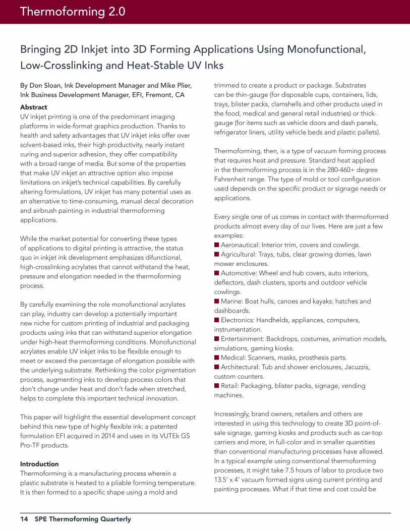
Bringing 2D Inkjet into 3D Forming Applications Using Monofunctional, Low-Crosslinking and Heat-Stable UV InksBy Don Sloan, Ink Development Manager and Mike Plier, Ink Business Development Manager, EFI, Fremont, CAAbstractUV inkjet printing is one of the predominant imaging platforms in wide-format graphics production. Thanks to health and safety advantages that UV inkjet inks offer over solvent-based inks, their high productivity, nearly instant curing and superior adhesion, they offer compatibility with a broad range of media. But some of the properties that make UV inkjet an attractive option also impose limitations on inkjet’s technical capabilities. By carefully altering formulations, UV inkjet has many potential uses as an alternative to time-consuming, manual decal decoration and airbrush painting in industrial thermoforming applications.
While the market potential for converting these types of applications to digital printing is attractive, the status quo in inkjet ink development emphasizes difunctional, high-crosslinking acrylates that cannot withstand the heat, pressure and elongation needed in the thermoforming process.
By carefully examining the role monofunctional acrylates can play, industry can develop a potentially important new niche for custom printing of industrial and packaging products using inks that can withstand superior elongation under high-heat thermoforming conditions. Monofunctional acrylates enable UV inkjet inks to be flexible enough to meet or exceed the percentage of elongation possible with the underlying substrate. Rethinking the color pigmentation process, augmenting inks to develop process colors that don’t change under heat and don’t fade when stretched, helps to complete this important technical innovation.
This paper will highlight the essential development concept behind this new type of highly flexible ink: a patented formulation EFI acquired in 2014 and uses in its VUTEk GS Pro-TF products.
IntroductionThermoforming is a manufacturing process wherein a plastic substrate is heated to a pliable forming temperature. It is then formed to a specific shape using a mold and
trimmed to create a product or package. Substrates can be thin-gauge (for disposable cups, containers, lids, trays, blister packs, clamshells and other products used in the food, medical and general retail industries) or thick-gauge (for items such as vehicle doors and dash panels, refrigerator liners, utility vehicle beds and plastic pallets).
Thermoforming, then, is a type of vacuum forming process that requires heat and pressure. Standard heat applied in the thermoforming process is in the 280-460+ degree Fahrenheit range. The type of mold or tool configuration used depends on the specific product or signage needs or applications.
Every single one of us comes in contact with thermoformed products almost every day of our lives. Here are just a few examples:n Aeronautical: Interior trim, covers and cowlings.n Agricultural: Trays, tubs, clear growing domes, lawn mower enclosures.n Automotive: Wheel and hub covers, auto interiors, deflectors, dash clusters, sports and outdoor vehicle cowlings.n Marine: Boat hulls, canoes and kayaks; hatches and dashboards.n Electronics: Handhelds, appliances, computers, instrumentation.n Entertainment: Backdrops, costumes, animation models, simulations, gaming kiosks.n Medical: Scanners, masks, prosthesis parts.n Architectural: Tub and shower enclosures, Jacuzzis, custom counters.n Retail: Packaging, blister packs, signage, vending machines.
Increasingly, brand owners, retailers and others are interested in using this technology to create 3D point-of-sale signage, gaming kiosks and products such as car-top carriers and more, in full-color and in smaller quantities than conventional manufacturing processes have allowed. In a typical example using conventional thermoforming processes, it might take 7.5 hours of labor to produce two 13.5’ x 4’ vacuum formed signs using current printing and painting processes. What if that time and cost could be
Thermoforming 2.0
SPE Thermoforming Quarterly 15
16 SPE Thermoforming Quarterly
significantly reduced?
Enter wide-format inkjet. As with any digital printing process, wide-format inkjet allows runs as short as one for fast-turn, highly customized materials for both samples and final product. Using digitally printed thermoforming technology, 34 of the same signs described above can be produced in the same 7.5 hours – a reduction of 93% in labor costs and an increase of productivity of 95%. Using conventional processes, these 34 signs would have taken 3.5 weeks to produce.
It is for this reason that digital printing technologies are attractive for thermoformed products. However, the inks used in digital wide-format inkjet printing have heretofore been inappropriate for these applications.
UV Inkjet Inks: The Status QuoThermoforming not only involves heat and pressure, it also requires elongation of the substrate to be formed. The status quo in inkjet ink development emphasizes difunctional, high-crosslinking acrylates that cannot withstand the heat and pressure needed in the thermoforming process. Nor can these inks stand up to the type of elongation required for most thermoforming applications.
During the heating cycle in the thermoforming process, both the inks and the plastic substrate become malleable. In the business, this is known as thermo-sag, glass transition phase or Bubble. Pigments can shift in color or hue during the heating or forming process. And elongation during forming can cause cracking or mosaic features in the final product that make it unacceptable from a quality perspective.
This is due to the fact that the difunctional acrylates commonly used in UV inkjet formulations have two highly reactive sites in their molecules for faster, harder curing, which add to an ink’s durability and productivity, but limit flexibility.
The advantages of UV inkjet formulations centered around difunctional, high-crosslinking acrylates include fast cure speeds, excellent chemical resistance and surface hardness. But for thermoforming applications, its disadvantages include limited adhesion ranges, brittleness and a tendency to experience shrinkage and edge-curl.
Exploring Monofunctional Acrylates for Thermoforming ApplicationsBy carefully examining the role monofunctional acrylates can play, the industry can develop a potentially important new niche for custom printing of industrial products using inks that can withstand superior elongation under high-heat thermoforming conditions. This technology can be utilized by traditional industrial thermoforming operators, but can also offer new revenue streams and expanded product offerings for printing companies with enhanced print capabilities by bringing imaging and decoration in house.
The result is high elongation 3D graphics with vivid color and visually compelling design capabilities.
Digital Thermoforming Inkjet Inks: The BackgroundDon Sloan has been developing UV printing inks since the 1970s. In 1993, he established Polymeric Imaging (PI) to create UV ink formulations to replace solvent-based chemistry. In 2010, PI developed a patented formulation for deep-draw thermoformable UV inkjet inks and coatings. PI’s patents and intellectual property related to digital thermoforming technology were acquired by EFI in October of 2014.
Less is More: Monofunctional, Low-Crosslinking AcrylatesThe original custom inkjet formulations for digital thermoformable UV inkjet inks and coatings worked well in PI lab tests but required years of refinement before they could be introduced to real-world production environments.
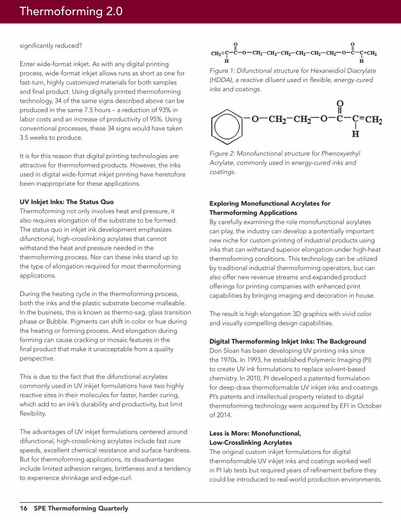
Figure 1: Difunctional structure for Hexaneidiol Diacrylate (HDDA), a reactive diluent used in flexible, energy-cured inks and coatings.
Figure 2: Monofunctional structure for Phenoxyethyl Acrylate, commonly used in energy-cured inks and coatings.
Thermoforming 2.0
SPE Thermoforming Quarterly 17
YOUR GO-TO-GUYS 877.289.7626 // [email protected] // buypmc.com
Innovation.New Products.Research & Development.
Texture delivers visual enhancement to speicalty formed parts. Applying texture or gloss to
a product adds richness, depth, and shine to a part’s appearance. From the glass-like finish
on the High Gloss to the intricate landscape of our new Swirl pattern, we provide a look that is
guaranteed to get noticed.
Smooth High Gloss Saddle Calf Seville Haircell
PMC OFFERS SIX DIFFERENT TEXTURES AND FINISHES
Swirl
NEW
Want to experience the PMC difference firsthand?
Contact your account executive to schedule your visit.
18 SPE Thermoforming Quarterly
Thermoforming 2.0
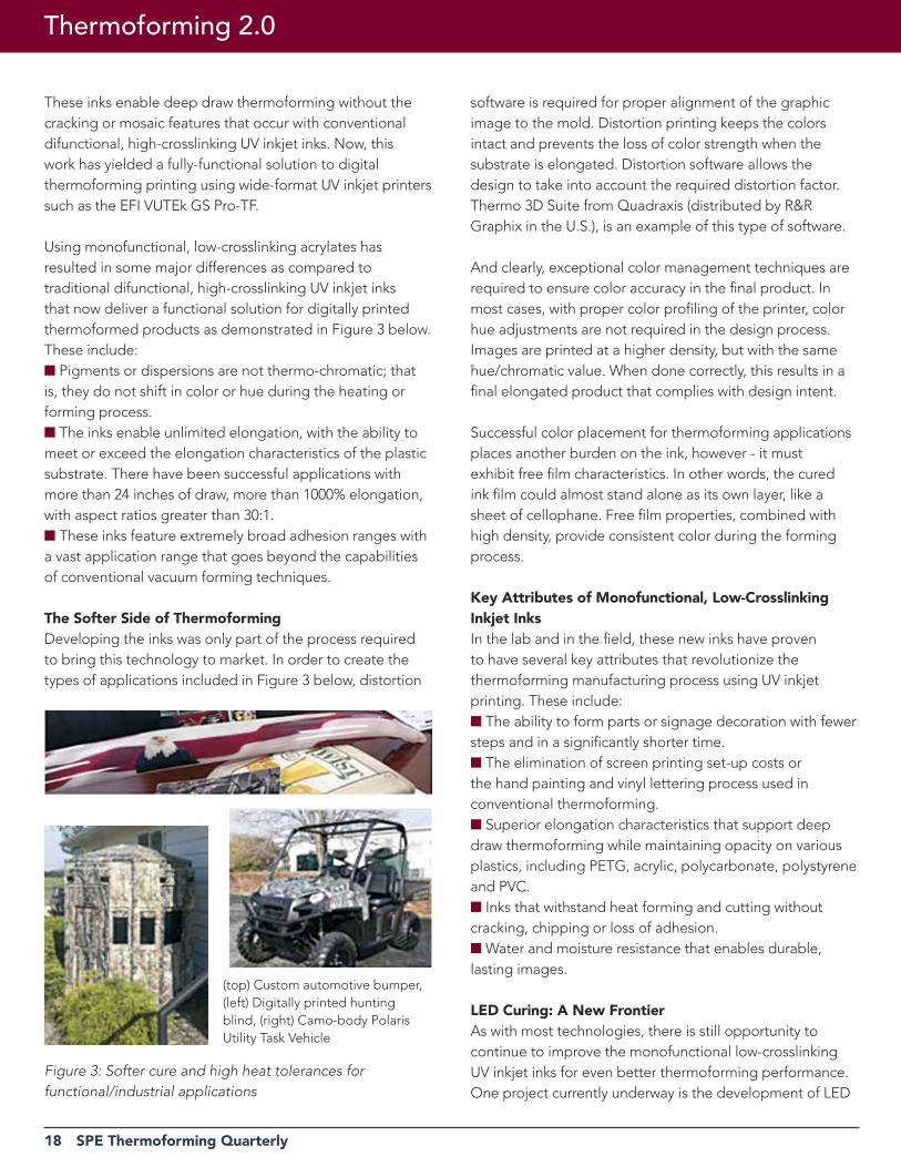
These inks enable deep draw thermoforming without the cracking or mosaic features that occur with conventional difunctional, high-crosslinking UV inkjet inks. Now, this work has yielded a fully-functional solution to digital thermoforming printing using wide-format UV inkjet printers such as the EFI VUTEk GS Pro-TF.
Using monofunctional, low-crosslinking acrylates has resulted in some major differences as compared to traditional difunctional, high-crosslinking UV inkjet inks that now deliver a functional solution for digitally printed thermoformed products as demonstrated in Figure 3 below. These include:n Pigments or dispersions are not thermo-chromatic; that is, they do not shift in color or hue during the heating or forming process.n The inks enable unlimited elongation, with the ability to meet or exceed the elongation characteristics of the plastic substrate. There have been successful applications with more than 24 inches of draw, more than 1000% elongation, with aspect ratios greater than 30:1.n These inks feature extremely broad adhesion ranges with a vast application range that goes beyond the capabilities of conventional vacuum forming techniques.
The Softer Side of ThermoformingDeveloping the inks was only part of the process required to bring this technology to market. In order to create the types of applications included in Figure 3 below, distortion
software is required for proper alignment of the graphic image to the mold. Distortion printing keeps the colors intact and prevents the loss of color strength when the substrate is elongated. Distortion software allows the design to take into account the required distortion factor. Thermo 3D Suite from Quadraxis (distributed by R&R Graphix in the U.S.), is an example of this type of software.
And clearly, exceptional color management techniques are required to ensure color accuracy in the final product. In most cases, with proper color profiling of the printer, color hue adjustments are not required in the design process. Images are printed at a higher density, but with the same hue/chromatic value. When done correctly, this results in a final elongated product that complies with design intent.
Successful color placement for thermoforming applications places another burden on the ink, however - it must exhibit free film characteristics. In other words, the cured ink film could almost stand alone as its own layer, like a sheet of cellophane. Free film properties, combined with high density, provide consistent color during the forming process.
Key Attributes of Monofunctional, Low-Crosslinking Inkjet InksIn the lab and in the field, these new inks have proven to have several key attributes that revolutionize the thermoforming manufacturing process using UV inkjet printing. These include:n The ability to form parts or signage decoration with fewer steps and in a significantly shorter time.n The elimination of screen printing set-up costs or the hand painting and vinyl lettering process used in conventional thermoforming.n Superior elongation characteristics that support deep draw thermoforming while maintaining opacity on various plastics, including PETG, acrylic, polycarbonate, polystyrene and PVC.n Inks that withstand heat forming and cutting without cracking, chipping or loss of adhesion.n Water and moisture resistance that enables durable, lasting images.
LED Curing: A New FrontierAs with most technologies, there is still opportunity to continue to improve the monofunctional low-crosslinking UV inkjet inks for even better thermoforming performance. One project currently underway is the development of LED
(top) Custom automotive bumper, (left) Digitally printed hunting blind, (right) Camo-body Polaris Utility Task Vehicle
Figure 3: Softer cure and high heat tolerances for functional/industrial applications
SPE Thermoforming Quarterly 19
cool cure ink formulations with LED-based photo-initiators using wavelengths of 365 to 400 nanometers, compared to conventional UV inks which use wavelengths of 320 to 365 nanometers. This leverages EFI’s LED inkjet expertise into the arena of thermoformable high elongation ink technology and enhancement coatings.
Conventional UV curing uses UV lights with an elevated temperature, which limits the ability to use lighter weight and heat-sensitive or dimensionally unstable substrates. LED curing takes place at 81 degrees Fahrenheit and results in increased material stability, lower distortion factors and reduced material degradation. As an added benefit, LED lamps feature extended lamp life and lower energy costs.
With LED curing, deep draw characteristics on a thin film could create new opportunities in vacuum forming by leveraging superior flexibility and color consistency in thin film packaging applications such as direct decorating for blister packs.
Process SimplificationIn addition, elongation during thermoforming, whether LED or conventionally cured, can translate into stretching profits and shrinking production costs. With a move toward packaging simplification, both for cost reduction and environmental sustainability reasons, thermoformed packaging has the potential to eliminate the need for cardboard inserts on packaging, and reduce cost and time in the packaging assembly process. Direct printing on the thermoformed packaging can also eliminate the need for labels. This offers the additional opportunity to use variable data on 3D plastic packaging for inclusion of bar codes, serialization and even personalization.
The Future is BrightThe technology advances that have been achieved in the development of monofunctional low-crosslinking UV inkjet inks for thermoforming opens up a bright new future for thermoformed applications across a number of industries as demonstrated by the examples cited in this paper. As this technology is adopted on a broader scale, it will result in:
n Faster time to market.n Higher quality, more relevant thermoformed products.n Reduction in the amount of packaging materials used.
The only limit is our imagination. This is just the beginning. |
Thermoforming Division Membership Benefitsn Access to industry knowledge from one central
location: www.thermoformingdivision.com.
n Subscription to Thermoforming Quarterly, voted “Publication of the Year” by SPE National.
n Exposure to new ideas and trends from across the globe.
n New and innovative part design at the Parts Competition.
n Open dialogue with the entire industry at the annual conference.
n Discounts, discounts, discounts on books, seminars and conferences.
n For managers: workshops and presentations tailored specifically to the needs of your operators.
n For operators: workshops and presentations that will send you home with new tools to improve your performance, make your job easier and help the company’s bottom line.
Become a SPE Thermoforming
Quarterly Sponsor in 2017!
Sponsorship opportunitiesinclude 4-color, full page, and
1/2 page ad spaces.
rESErVE yOUr PrIME SPONSOrSHIP SPACE TODAy.
Questions? Call or emailLesley Kyle
20 SPE Thermoforming Quarterly
Thermoforming 2.0
Hybrid Thermoforming = Thickness Design Freedom By Jerry Dees, Engineering Simulations LLC, Appleton, WI
IntroductionHybrid thermoforming starts with a designed, non-uniform thickness pre-form and results in a thermoformed part with a specified final thickness distribution. The key new development is a pre-form design technique that starts with the desired final product thickness distribution. It involves an iterative series of finite element analysis (FEA) simulations of the forming process converging on the required thickness distribution of the pre-form.Hybrid thermoforming replaces the conventional extruded uniform thickness polymer sheet with a designed, non-uniform thickness, compression molded, pre-form. Alternatively, a uniform thickness sheet could be compression-molded to rearrange the thickness to the desired levels. This may allow higher volume parts to use the hybrid thermoforming technique. The primary advantage of hybrid thermoforming is the design freedom to specify the final thickness distribution in the part. Also the design could include the addition of localized areas of increased thickness for stiffening ribs or design patterns. Additional advantages include the elimination of sheet extrusion and reheat when a pre-form is used, reduced material costs, cycle time reduction, reduced scrap, and elimination of the plug assist.
Hybrid thermoforming is in the early stages of development and its potential and limitations are currently being investigated. This paper will discuss the compression molded pre-form design procedure for a uniform thickness part and the same part with a stiffening ring, along with laboratory verification and prototyping of the two hybrid thermoformed products.
New Niche for ThermoformingIn addition to improving the performance and cost of thermoformed products, hybrid thermoforming could also create a new niche, thereby expanding the thermoforming industry.
Conventional thermoforming allows the production of relatively thin-walled parts, with minimum thicknesses down to about 0.005” (0.125 mm). While there are many variations of the thermoforming process to influence the
part thickness, specification of the final part thickness distribution is very limited. Also, the starting sheet thickness is often governed by a minimum thickness at the corners of a part, which results in other areas being unnecessarily thick, increasing material costs and cycle time.
Conventional injection molding, inherently more expensive than thermoforming, allows the production of plastic parts with a designed thickness distribution and stiffening ribs, but the thinnest parts are thick relative to thermoforming. Due to limitations of polymer flow between mold halves, the thinnest injection molded parts are about 0.070” (1.78 mm), unless an even more expensive thin wall injection molding process is used. Thus, there is a gap in the forming capabilities between the conventional thermoforming and conventional injection molding processes, in the forming of thin-walled parts with a specified or designed thickness distribution and stiffening ribs. That niche could be filled by the more cost effective hybrid thermoforming process, allowing thin-walled parts with a designed thickness distribution.
History of Pre-forms in ThermoformingThere has been previous development work related to using pre-forms, or billets, with thermoforming. It appears, however, that previous efforts all used uniformly thick pre-forms. The primary examples of past work with pre-forms in thermoforming are as follows:n In 1963 a patent for a method of forming containers using injection molded pre-forms, a heated “plunger” or plug assist, and pressure thermoforming was granted1. n In the 1970’s, Dow Chemical developed and patented a technique that they called the Scrapless Forming Process2. For this technique, powdered polymer was heated to just below the melt temperature and compressed into briquettes. The softened briquettes were then compressed into pre-forms and taken directly to the thermoforming station or cooled and thermoformed later. n A version of the Dow Chemical process was commercialized in the 1980’s by SFP Container 3. In SFP’s system, squares were cut from an extruded sheet, lubricated, heated in an oven and placed in lip rings. There the squares were forged between anvils into round pre-forms. The forging process added biaxial orientation to improve impact and tensile strength.
SPE Thermoforming Quarterly 21
Figure 1: Proposed hybrid thermoforming process
n Another version of the scrapless forming process was developed by the Shell Chemical Company in the 1960’s called billet forming 4. It was commercialized and patented in the 1980’s by QuesTech Ventures. In QuesTech’s process, billets in the shape of the container (round, square, rectangular) are punched from sheet and heated to the melt-phase forming temperatures. The softened billets were then pressure formed into the product shape using a plug assist. n In 2003, PBM Plastics commercialized a process called melt-phase billet forming that claims to be a hybrid of thermoforming and blow molding 5. The process punched donut-shaped billets, of predetermined diameter and thickness from a sheet. In the process the billets were heated precisely to the melting point, and then forced into a mold with a plug assist and air pressure. n In a more recent development, Sacmi Imola S.C. of Italy commercialized a process for the compression molding of PET pre-forms for blow molding6, replacing the injection molded pre-form. In this process, a measured amount of the PET material is extruded from a vertical die and is cut by a knife into a slug. The slugs are then inserted into a compression mold and the pre-form is formed. The pre-forms are then cooled for later bottle forming. Generally, pre-forms for injection blow-molded bottles are non-uniform in thickness, in an attempt to have the bottles be at some specified thickness. Published reports, however, do not indicate the use of a design technique for the pre-form thickness distribution in compression blow molding.
Proposed Hybrid Thermoforming ConceptThe hybrid thermoforming process is a combination of some aspects of the scrapless forming process and some features of compression or injection blow molding. The scrapless forming process starts with a uniform thickness flat pre-form while compression or injection blow molding starts with a non-uniform cylindrical pre-form.
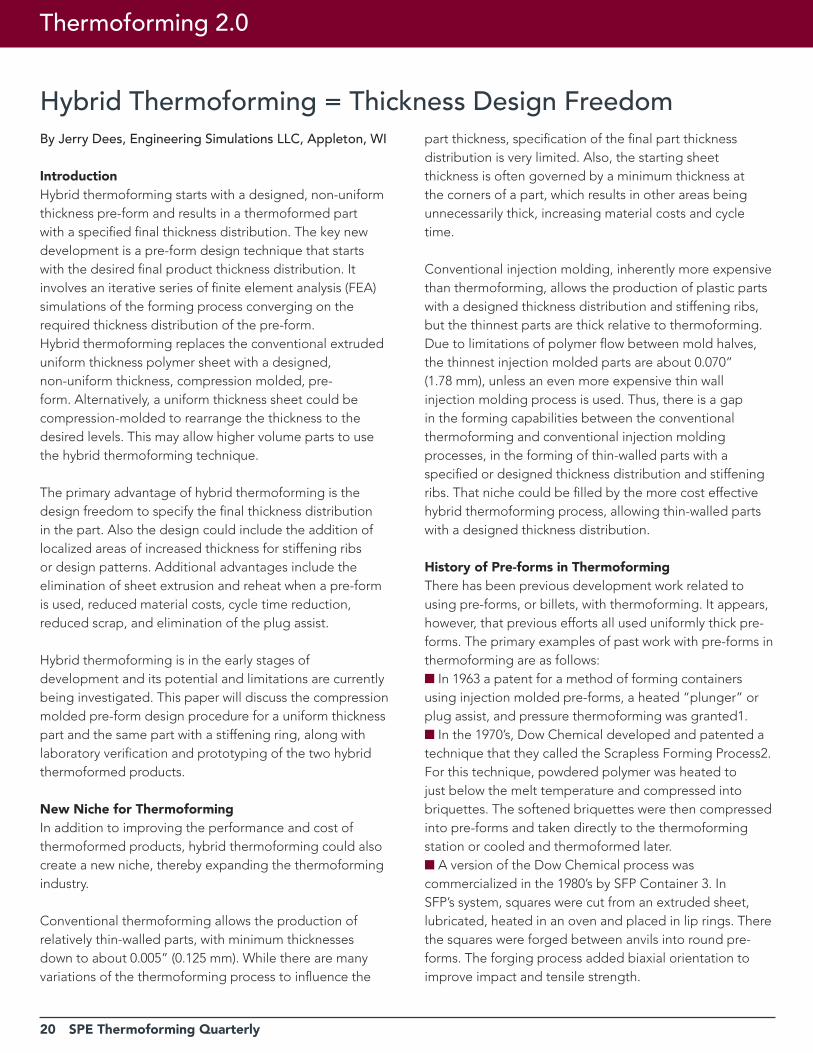
A proposed process method for hybrid thermoforming involves compression molding a non-uniform pre-form and thermoforming it in-line. The proposed hybrid thermoforming process is illustrated in Figure 1. The start of the process would be similar to the compression blow molding pre-form process, extruding a slug of polymer material onto the compression mold. A potential, but yet untested technique, would extrude the slug
onto a porous aluminum plate. The porous aluminum plate would have machined into its surface the designed thickness distribution of the pre-form. The pre-form would be compression molded on the porous aluminum plate. The pre-form would stay with the aluminum plate and be conditioned to the thermoforming temperature window for the polymer. The polymer disk, still supported by the porous aluminum plate would be transported to the forming station where pressure under the porous aluminum plate and vacuum in the mold would force the polymer disk off the plate and into contact with the mold.
Alternatively, a uniform thickness polymer sheet could be compression molded to rearrange the pre-form thickness to the required thickness distribution. This may be a way for higher volume products to be formed with hybrid thermoforming.
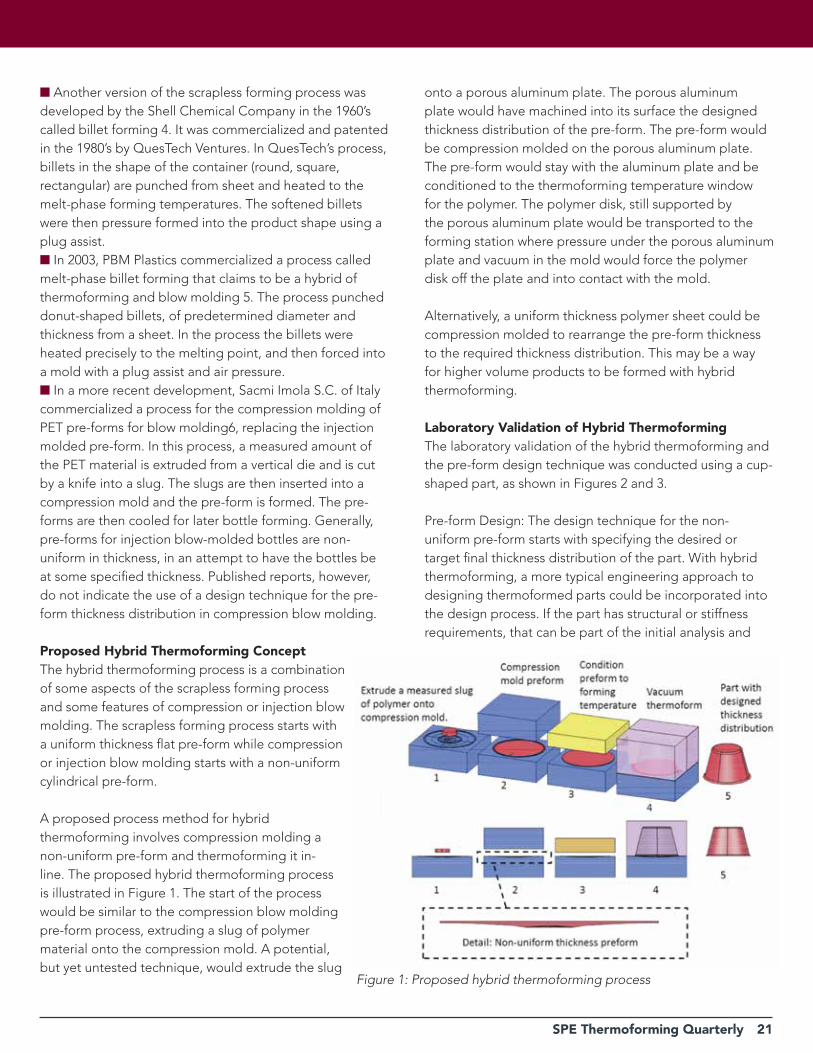
Laboratory Validation of Hybrid Thermoforming The laboratory validation of the hybrid thermoforming and the pre-form design technique was conducted using a cup-shaped part, as shown in Figures 2 and 3.
Pre-form Design: The design technique for the non-uniform pre-form starts with specifying the desired or target final thickness distribution of the part. With hybrid thermoforming, a more typical engineering approach to designing thermoformed parts could be incorporated into the design process. If the part has structural or stiffness requirements, that can be part of the initial analysis and
22 SPE Thermoforming Quarterly
Thermoforming 2.0
design. A structural analysis and design could be done to achieve the desired characteristics before the first prototype is made, as is done in most other industries. Also, stiffening rings or ribs, decorative raised areas, logos, or grip enhancement features could be added to the thermoformed part. The desired design thickness distribution becomes the targets for the pre-form design.
The design technique for the pre-form involves conducting a series of FEA simulations that converge on the required pre-form thickness distribution to achieve the specified thickness distribution in the thermoformed product. The starting point for the first iteration of the pre-form is a uniform thickness. The FEA simulates the thermoforming process and depending on where each node in the model lands, the pre-form thickness distribution for the next iteration is modified. The iterative process continues until the final part thickness, in the simulation, is within a specified limit.
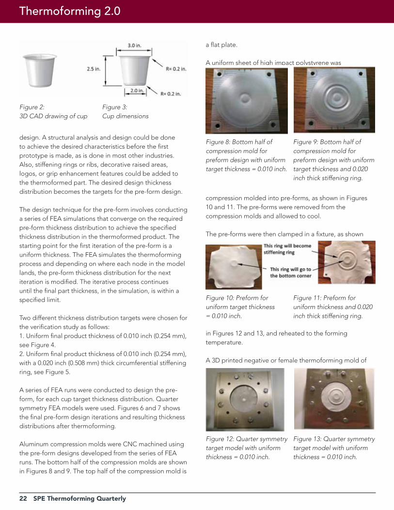
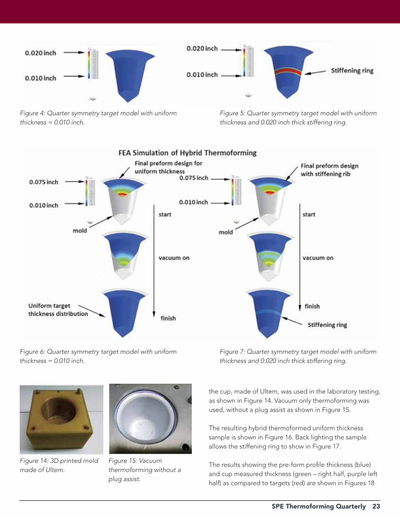
Two different thickness distribution targets were chosen for the verification study as follows:1. Uniform final product thickness of 0.010 inch (0.254 mm), see Figure 4.2. Uniform final product thickness of 0.010 inch (0.254 mm), with a 0.020 inch (0.508 mm) thick circumferential stiffening ring, see Figure 5.
A series of FEA runs were conducted to design the pre-form, for each cup target thickness distribution. Quarter symmetry FEA models were used. Figures 6 and 7 shows the final pre-form design iterations and resulting thickness distributions after thermoforming.
Aluminum compression molds were CNC machined using the pre-form designs developed from the series of FEA runs. The bottom half of the compression molds are shown in Figures 8 and 9. The top half of the compression mold is
a flat plate.
A uniform sheet of high impact polystyrene was
compression molded into pre-forms, as shown in Figures 10 and 11. The pre-forms were removed from the compression molds and allowed to cool.
The pre-forms were then clamped in a fixture, as shown
in Figures 12 and 13, and reheated to the forming temperature.
A 3D printed negative or female thermoforming mold of
Figure 2: 3D CAD drawing of cup
Figure 3: Cup dimensions
Figure 8: Bottom half of compression mold for preform design with uniform target thickness = 0.010 inch.
Figure 9: Bottom half of compression mold for preform design with uniform target thickness and 0.020 inch thick stiffening ring.
Figure 10: Preform for uniform target thickness = 0.010 inch.
Figure 11: Preform for uniform thickness and 0.020 inch thick stiffening ring.
Figure 12: Quarter symmetry target model with uniform thickness = 0.010 inch.
Figure 13: Quarter symmetry target model with uniform thickness = 0.010 inch.
SPE Thermoforming Quarterly 23
Figure 4: Quarter symmetry target model with uniform thickness = 0.010 inch.
Figure 6: Quarter symmetry target model with uniform thickness = 0.010 inch.
Figure 5: Quarter symmetry target model with uniform thickness and 0.020 inch thick stiffering ring.
Figure 7: Quarter symmetry target model with uniform thickness and 0.020 inch thick stiffering ring.
the cup, made of Ultem, was used in the laboratory testing, as shown in Figure 14. Vacuum only thermoforming was used, without a plug assist as shown in Figure 15.
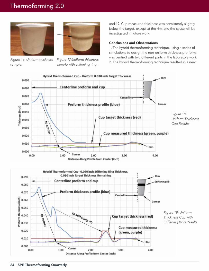
The resulting hybrid thermoformed uniform thickness sample is shown in Figure 16. Back lighting the sample allows the stiffening ring to show in Figure 17.
The results showing the pre-form profile thickness (blue) and cup measured thickness (green – right half, purple left half) as compared to targets (red) are shown in Figures 18
Figure 14: 3D printed mold made of Ultem.
Figure 15: Vacuum thermoforming without a plug assist.
24 SPE Thermoforming Quarterly
and 19. Cup measured thickness was consistently slightly below the target, except at the rim, and the cause will be investigated in future work.
Conclusions and Observations1. The hybrid thermoforming technique, using a series of simulations to design the non-uniform thickness pre-form, was verified with two different parts in the laboratory work.2. The hybrid thermoforming technique resulted in a near
Figure 16: Uniform thickness sample.
Figure 17:Uniform thickness sample with stiffening ring.
Figure 18: Uniform Thickness Cup Results
Figure 19: Uniform Thickness Cup with Stiffening Ring Results
Thermoforming 2.0
SPE Thermoforming Quarterly 25
uniform thickness thermoformed part. Future work will attempt to understand why the final thickness was slightly below the target.3. The hybrid thermoforming technique also produced a near uniform thickness part with a specified thickness stiffening ring.4. With a female (negative) mold, the raised thickness stiffening ring was on the inside surface, no matter the orientation or the pre-form. Future work with a male (positive) mold will place the raised thickness on the outside surface of the part.
Potential Benefits of Hybrid Thermoformingn Design freedom for thermoformed products: Hybrid thermoforming part design could start with the question, “What thickness distribution is best or desired for the product?” Conversely, conventional thermoforming part design starts with the question, “What thickness distribution is allowed by the process?” n New niche for thermoforming: Hybrid thermoforming could bridge the present gap between injection molding and existing thermoforming methods, producing relatively thin walled parts with a specified thickness distribution and stiffening ribs.n Material cost savings: Elimination of unnecessary thick areas that occur in conventional thermoforming could significantly reduce the amount of material in thermoformed parts. n Energy and time savings: The process could eliminate the need to extrude a sheet and then reheat it prior to thermoforming.n Eliminate the plug assist: The pre-form thickness distribution is designed such that a plug assist would not be necessary.n Reduced scrap: Potentially eliminates unused areas of a sheet between mold cavities.n Reduced cycle time: Eliminating unnecessary thick areas in parts would decrease cycle time.
Future Workn Improved design technique for the preform: Presently, each iteration of the design is done semi-manually. A more automated version of the design technique may be developed.n Process development for commercial applications: There is much work to be done on the process, how best to form the non-uniform thickness pre-form, and how far the non-uniformity can be pushed.n Hybrid thermoforming with a male or positive mold:
A male mold would place the stiffening ribs and raised thickness areas on the outside of the part.n Improved compression molding: Methods to improve the surface quality of the compression molded pre-forms will be examined.
References1. Whiteford, C., “Method of Forming Container” U.S. Patent 3,184,524
2. Stube,S. and Chisholm,D.: “Process for Scrapless Forming of Plastic Articles”, U.S. Patent 4,014,965
3. Schut, J., Plastics Technology, June 1, 1992
4. Schut, J., Plastics Technology, June 1, 1992
5. Leaversuch, R., Plastics Technology, Jan 1, 2003
6. Naitove, M., Plastics Technology, March 2, 2009 |
26 SPE Thermoforming Quarterly
A Holistic Approach to Sheet Fed Tooling Development
Industry Practice
By Mauro Fae, Self Group, Udinese, Italy, in collaboration with Roger C. Kipp
When evaluating tooling design, it is critical to take a holistic approach. One must consider the whole picture. The totality of final tool design is much greater than the sum of its component specifications and the design cannot be completed by the examination of those specifications alone. The completed tooling design will need to balance the following key factors:
1. Design For: What is the ideal process and the best tooling material to achieve the desired application requirements? What is the available equipment?2. Process Know-how: Tool-making requires expertise with the desired process and material.3. Tool-making Expertise: Tool-making competency will provide design support and solutions from previous experience.4. Lean: Lean Production Principles practiced in the toolmaking process and incorporated into the tool design results in the most efficient tools5. Simulation: The use of simulation software prior to final tool design for design verification to avoid alterations and production startup delays.6. Competencies and Passion: The tool-making process requires early involvement, ideas and designs displaying competence, confidence and enthusiasm from the entire team.7. Project Management: What systems and processes will be incorporated to manage the build? Are those systems compatible?
While all of these factors were in play for the case study below, we focus on a subset that includes product overview and customer requests, process analysis, assumptions in mold design, and simulation.
The approach requires an efficient method to analyze the process that we will refer to as Design For X where X can be:n Functionalityn Aestheticsn Environmentn Production Requirementsn Processing methodn Processing Equipment
n Assemblyn Packagingn Transportationn Other
These “X” factors are cross-linked and connected in defining the final tooling design.
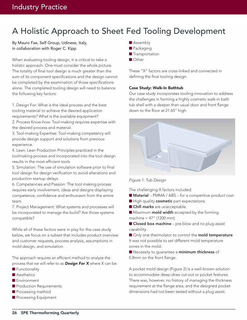
Case Study: Walk-In BathtubOur case study incorporates tooling innovation to address the challenges in forming a highly cosmetic walk-in bath tub shell with a deeper than usual door and front flange down to the floor at 21.65” high.
The challenging X factors included:n Material – PMMA / ABS – for a competitive product cost.n High quality cosmetic part expectations.n Chill marks are unacceptable.n Maximum mold width accepted by the forming machine = 47” (1200 mm).n Closed box machine – pre blow and no plug-assist capability.n Only one thermolator to control the mold temperature. It was not possible to set different mold temperature zones in the mold.n Necessity to guarantee a minimum thickness of 0.8mm on the front flange.
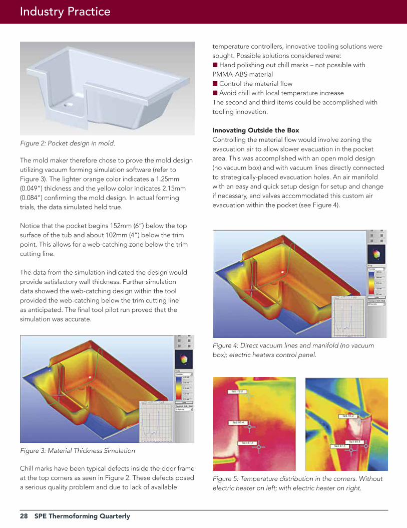
A pocket mold design (Figure 2) is a well-known solution to accommodate deep-draw cut-out or pocket features. There was, however, no history of managing the thickness requirement at the flange area, and the designed pocket dimensions had not been tested without a plug assist.
Figure 1: Tub Design
SPE Thermoforming Quarterly 27
28 SPE Thermoforming Quarterly
Industry Practice
The mold maker therefore chose to prove the mold design utilizing vacuum forming simulation software (refer to Figure 3). The lighter orange color indicates a 1.25mm (0.049”) thickness and the yellow color indicates 2.15mm (0.084”) confirming the mold design. In actual forming trials, the data simulated held true.
Notice that the pocket begins 152mm (6”) below the top surface of the tub and about 102mm (4”) below the trim point. This allows for a web-catching zone below the trim cutting line.
The data from the simulation indicated the design would provide satisfactory wall thickness. Further simulation data showed the web-catching design within the tool provided the web-catching below the trim cutting line as anticipated. The final tool pilot run proved that the simulation was accurate.
Chill marks have been typical defects inside the door frame at the top corners as seen in Figure 2. These defects posed a serious quality problem and due to lack of available
temperature controllers, innovative tooling solutions were sought. Possible solutions considered were:n Hand polishing out chill marks – not possible with PMMA-ABS materialn Control the material flown Avoid chill with local temperature increase The second and third items could be accomplished with tooling innovation.
Innovating Outside the BoxControlling the material flow would involve zoning the evacuation air to allow slower evacuation in the pocket area. This was accomplished with an open mold design (no vacuum box) and with vacuum lines directly connected to strategically-placed evacuation holes. An air manifold with an easy and quick setup design for setup and change if necessary, and valves accommodated this custom air evacuation within the pocket (see Figure 4).
Figure 2: Pocket design in mold.
Figure 5: Temperature distribution in the corners. Without electric heater on left; with electric heater on right.
Figure 3: Material Thickness Simulation
Figure 4: Direct vacuum lines and manifold (no vacuum box); electric heaters control panel.
SPE Thermoforming Quarterly 29
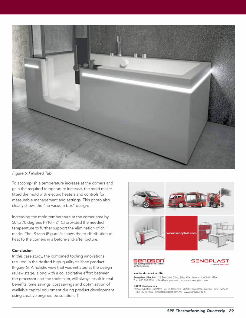
To accomplish a temperature increase at the corners and gain the required temperature increase, the mold maker fitted the mold with electric heaters and controls for measurable management and settings. This photo also clearly shows the “no vacuum box” design.
Increasing the mold temperature at the corner area by 50 to 70 degrees F (10 – 21 C) provided the needed temperature to further support the elimination of chill marks. The IR scan (Figure 5) shows the re-distribution of heat to the corners in a before-and-after picture.
ConclusionIn this case study, the combined tooling innovations resulted in the desired high-quality finished product (Figure 6). A holistic view that was initiated at the design review stage, along with a collaborative effort between the processor and the toolmaker, will always result in real benefits: time savings, cost savings and optimization of available capital equipment during product development using creative engineered solutions. |
Figure 6: Finished Tub
high quality plastic sheets and fi lms for thermoforming
www.senoplast.com
a member of klepsch group
Your local contact in USA:
Senoplast USA, Inc. · 75 Executive Drive, Suite 129 · Aurora · IL 60504 · USAT +1 630 898 0731 · offi [email protected] · www.senoplast.com
NAFTA HeadquartersParque Industrial Querétaro · Av. La Noria 123 · 76220 Santa Rosa Jáuregui · Qro. · MexicoT +52 422 19 4600 · offi [email protected] · www.senoplast.com
sen_az_en_93x102_rz.indd 1 28.02.2017 09:25:28
30 SPE Thermoforming Quarterly
Industry Practice
Managing Wall Thickness Variation in Thermoformed PartsBy Kathleen Boivin, Sr. Materials Engineer & Conor Carlin, Sales & Marketing Manager, CMT Materials, Inc., Attleboro, MA
Editor’s note: this paper has been adapted from a presentation originally delivered at the AMI Thin Wall Packaging Conference North America in May 2017.
Let’s acknowledge a few things about thermoforming. Sometimes known as the black art of plastics processing and only slightly less precise than injection molding, there is a wide range of products that are made via this process today. The technology continues to advance: machines are faster, tools are more precise, materials are more complex. Market demands exert a strong pull on production managers, a few of which acknowledge that getting product out the door often takes precedence over a longer-term view of things. One thermoforming plant displays a large whiteboard in the production area: “Patience isn’t a virtue; it’s a waste of time.”
But there is a science to it, as the publications of Dr. James Throne will attest. (Who doesn’t love a good meeting to discuss the energy density function for an incompressible Mooney-Rivlin material?) It is true that there are a lot of variables in thermoforming. We might not want to deal with all of them, but knowing what they are is probably not a bad idea. In our little corner of the composite material world, the humble plug assist can get complicated quite quickly.
Speaking of science, let’s try an analogy to illustrate how plugs have come to be an integral component of the thermoforming process. Fire and its descendants provided heat and light, but you can’t control them via a smartphone app in your house. A lot of things will move plastic in its heated state, but that doesn’t mean you should use them. Materials technology continues to evolve.
Context is EverythingWhen we go to trade shows, the most common question we hear is, “What is the best plug material for X?” As much as we would love to have a simple answer, the reality is that what happens at the interface of the plug and the heated material is complex. So, even though ‘it depends’ is a bit of a socratic answer, more detail is usually required before
anyone can make an informed plug material selection.
Context is important. Your view of the world is slightly different depending on how vertically integrated you are – that is, are you making your own tools in-house or having them made on the outside? But since we are discussing how to manage wall thickness variation, let’s assume we’re all thermoforming processors: what should we know? Polymer type, obviously, but are we talking about virgin? PCR? Multilayer? Ideally, some type of material characterization would be instructive. What are the machine’s capabilities; what is the desired part weight; what other critical design concerns does the end customer have? Clarity? Stiffness? Cocentricity? Is the part going to be used in a form/fill/seal application?
Let’s consider the economic context for spending this much time discussing plug materials. On average, across different types of parts, the plastic used to form the part makes up the majority of its cost. Seeing as how the plug is essentially the first thing that touches the plastic, it probably makes sense to understand the impact it might have on how much plastic is actually required to form a good part.
Going Down the rabbit HoleWhat happens when you really want to know what happens at the interface of the plug and sheet? Well, you get a design of experiment, that’s what. Let’s go a level deeper. Design of experiment (DOE) is a systematic method to determine the relationship between factors affecting a process and the output of that process. In other words, it is used to find cause-and-effect relationships. This information is needed to manage process inputs in order to optimize the output. We’ve done a few of these over the years and presented findings at ANTEC and published a few papers. Specifically, our approach focuses on the ability to measure the interfacial interaction between plug assist and sheet during thermoforming. We executed a statistically-designed plan and the results were analyzed to determine the magnitude and direction of the influence of the individual factors on the measured properties of the thermoformed part.
The test plan evaluated the effects of seven factors on

SPE Thermoforming Quarterly 31
32 SPE Thermoforming Quarterly
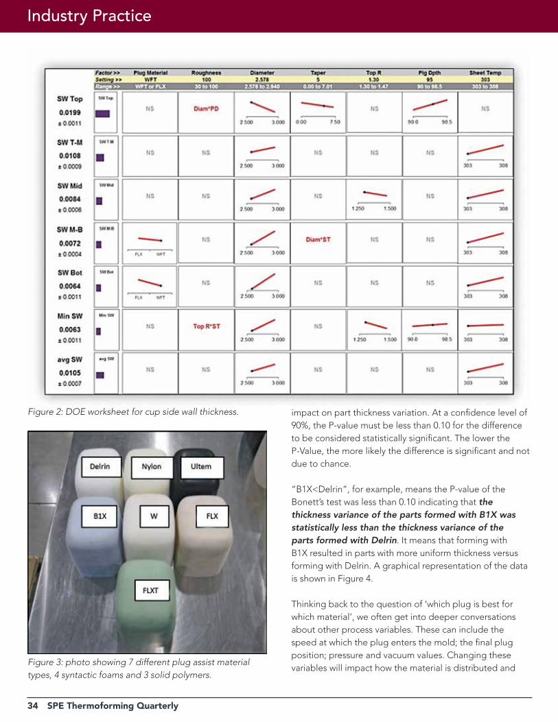
the measured properties in a relatively small number of trials. We found several, 2-factor interactions that would not otherwise have been revealed through the empirical method of varying one factor at a time. The factors having the most effect on properties were plug diameter, sheet temperature and plug material. The analysis led to the development of worksheets which allow one to vary the factor levels (within the range studied) to optimize key responses. Figure 2 shows the worksheet for cup side wall thickness. As an example, using FLX instead of WFT results in maximum side wall thickness at the mid-bottom and bottom positions. WFT is impregnated with PTFE (polytetrafluoroethylene) while FLX is has a co-polymer base. Compared to WFT, FLX has a greater coefficient of friction at the plug-sheet interface which pushes more material towards the bottom of a part.
Phase I Test resultsCMT recently concluded the first phase of a multi-phase collaborative field trial with industry partners. The primary goal of these experiments was to isolate the plug material as a variable in the forming process. Of course, many variables are interrelated, but when asking “how much is 1 mil worth”, we wanted to explore the impact that a simple plug material change would have. We used a statistical
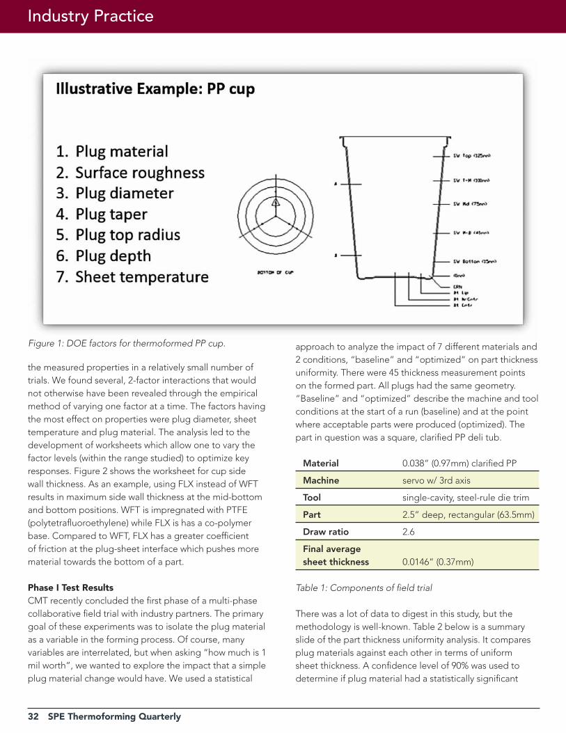
approach to analyze the impact of 7 different materials and 2 conditions, “baseline” and “optimized” on part thickness uniformity. There were 45 thickness measurement points on the formed part. All plugs had the same geometry. “Baseline” and “optimized” describe the machine and tool conditions at the start of a run (baseline) and at the point where acceptable parts were produced (optimized). The part in question was a square, clarified PP deli tub.
Material 0.038” (0.97mm) clarified PP
Machine servo w/ 3rd axis
Tool single-cavity, steel-rule die trim
Part 2.5” deep, rectangular (63.5mm)
Draw ratio 2.6
Final average sheet thickness 0.0146” (0.37mm)
Table 1: Components of field trial
There was a lot of data to digest in this study, but the methodology is well-known. Table 2 below is a summary slide of the part thickness uniformity analysis. It compares plug materials against each other in terms of uniform sheet thickness. A confidence level of 90% was used to determine if plug material had a statistically significant
Figure 1: DOE factors for thermoformed PP cup.
Industry Practice

SPE Thermoforming Quarterly 33
34 SPE Thermoforming Quarterly
Industry Practice
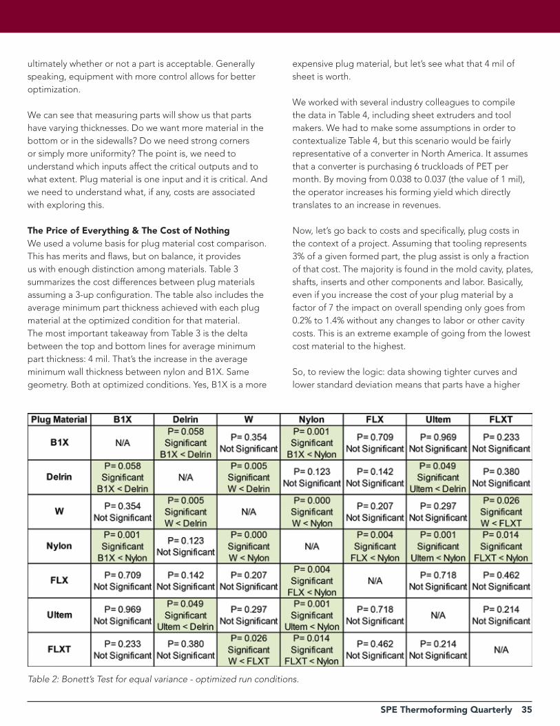
impact on part thickness variation. At a confidence level of 90%, the P-value must be less than 0.10 for the difference to be considered statistically significant. The lower the P-Value, the more likely the difference is significant and not due to chance.
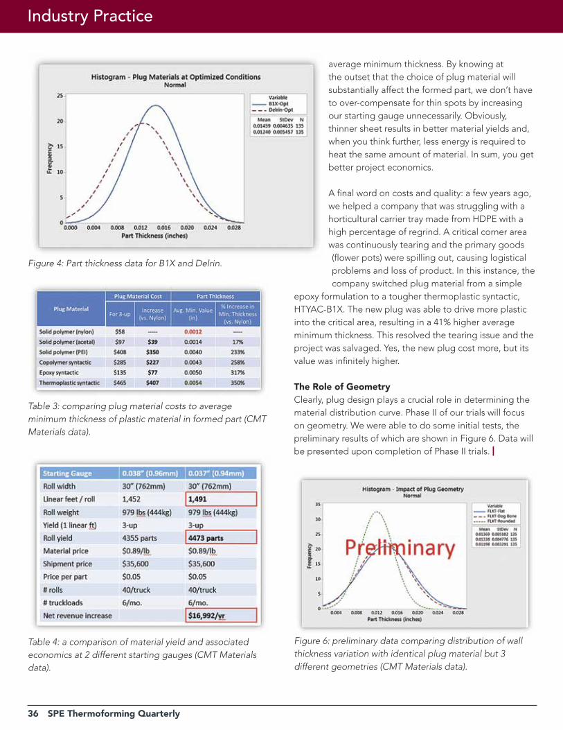
“B1X<Delrin”, for example, means the P-value of the Bonett’s test was less than 0.10 indicating that the thickness variance of the parts formed with B1X was statistically less than the thickness variance of the parts formed with Delrin. It means that forming with B1X resulted in parts with more uniform thickness versus forming with Delrin. A graphical representation of the data is shown in Figure 4.
Thinking back to the question of ‘which plug is best for which material’, we often get into deeper conversations about other process variables. These can include the speed at which the plug enters the mold; the final plug position; pressure and vacuum values. Changing these variables will impact how the material is distributed and
Figure 2: DOE worksheet for cup side wall thickness.
Figure 3: photo showing 7 different plug assist material types, 4 syntactic foams and 3 solid polymers.
SPE Thermoforming Quarterly 35
ultimately whether or not a part is acceptable. Generally speaking, equipment with more control allows for better optimization.
We can see that measuring parts will show us that parts have varying thicknesses. Do we want more material in the bottom or in the sidewalls? Do we need strong corners or simply more uniformity? The point is, we need to understand which inputs affect the critical outputs and to what extent. Plug material is one input and it is critical. And we need to understand what, if any, costs are associated with exploring this.
The Price of Everything & The Cost of NothingWe used a volume basis for plug material cost comparison. This has merits and flaws, but on balance, it provides us with enough distinction among materials. Table 3 summarizes the cost differences between plug materials assuming a 3-up configuration. The table also includes the average minimum part thickness achieved with each plug material at the optimized condition for that material. The most important takeaway from Table 3 is the delta between the top and bottom lines for average minimum part thickness: 4 mil. That’s the increase in the average minimum wall thickness between nylon and B1X. Same geometry. Both at optimized conditions. Yes, B1X is a more
Table 2: Bonett’s Test for equal variance - optimized run conditions.
expensive plug material, but let’s see what that 4 mil of sheet is worth.
We worked with several industry colleagues to compile the data in Table 4, including sheet extruders and tool makers. We had to make some assumptions in order to contextualize Table 4, but this scenario would be fairly representative of a converter in North America. It assumes that a converter is purchasing 6 truckloads of PET per month. By moving from 0.038 to 0.037 (the value of 1 mil), the operator increases his forming yield which directly translates to an increase in revenues.
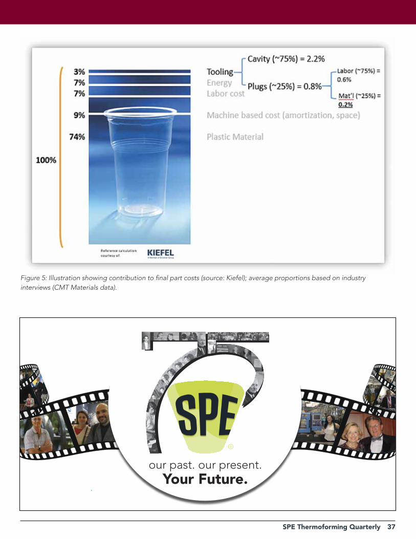
Now, let’s go back to costs and specifically, plug costs in the context of a project. Assuming that tooling represents 3% of a given formed part, the plug assist is only a fraction of that cost. The majority is found in the mold cavity, plates, shafts, inserts and other components and labor. Basically, even if you increase the cost of your plug material by a factor of 7 the impact on overall spending only goes from 0.2% to 1.4% without any changes to labor or other cavity costs. This is an extreme example of going from the lowest cost material to the highest.
So, to review the logic: data showing tighter curves and lower standard deviation means that parts have a higher
36 SPE Thermoforming Quarterly
Industry Practice
Figure 6: preliminary data comparing distribution of wall thickness variation with identical plug material but 3 different geometries (CMT Materials data).
Table 3: comparing plug material costs to average minimum thickness of plastic material in formed part (CMT Materials data).
Table 4: a comparison of material yield and associated economics at 2 different starting gauges (CMT Materials data).
average minimum thickness. By knowing at the outset that the choice of plug material will substantially affect the formed part, we don’t have to over-compensate for thin spots by increasing our starting gauge unnecessarily. Obviously, thinner sheet results in better material yields and, when you think further, less energy is required to heat the same amount of material. In sum, you get better project economics.
A final word on costs and quality: a few years ago, we helped a company that was struggling with a horticultural carrier tray made from HDPE with a high percentage of regrind. A critical corner area was continuously tearing and the primary goods (flower pots) were spilling out, causing logistical problems and loss of product. In this instance, the company switched plug material from a simple
epoxy formulation to a tougher thermoplastic syntactic, HTYAC-B1X. The new plug was able to drive more plastic into the critical area, resulting in a 41% higher average minimum thickness. This resolved the tearing issue and the project was salvaged. Yes, the new plug cost more, but its value was infinitely higher.
The role of GeometryClearly, plug design plays a crucial role in determining the material distribution curve. Phase II of our trials will focus on geometry. We were able to do some initial tests, the preliminary results of which are shown in Figure 6. Data will be presented upon completion of Phase II trials. |
Figure 4: Part thickness data for B1X and Delrin.
SPE Thermoforming Quarterly 37
Figure 5: Illustration showing contribution to final part costs (source: Kiefel); average proportions based on industry interviews (CMT Materials data).
our past. our present.Your Future.
38 SPE Thermoforming Quarterly
How Important is the Volumetric Absorption Concept?Part 2: Model Building
Lead Technical Article
By Jim Throne, Consultant, Dunedin, FL
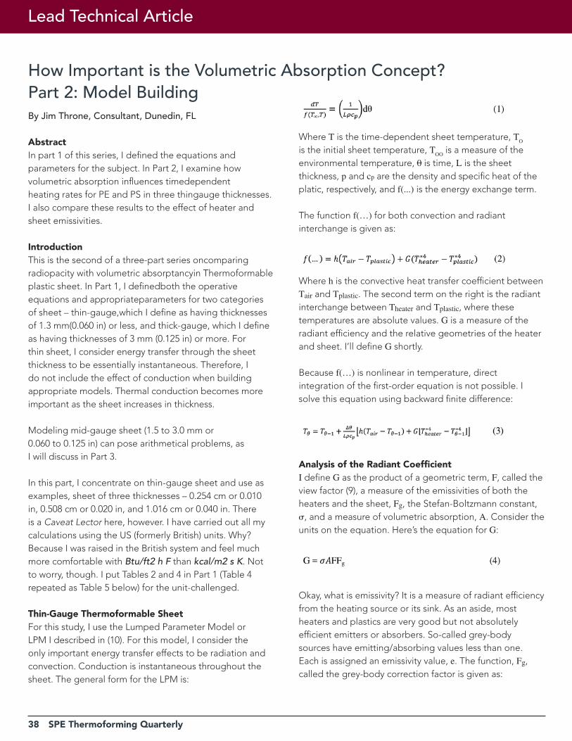
AbstractIn part 1 of this series, I defined the equations and parameters for the subject. In Part 2, I examine how volumetric absorption influences timedependentheating rates for PE and PS in three thingauge thicknesses. I also compare these results to the effect of heater and sheet emissivities.
IntroductionThis is the second of a three-part series oncomparing radiopacity with volumetric absorptancyin Thermoformable plastic sheet. In Part 1, I definedboth the operative equations and appropriateparameters for two categories of sheet – thin-gauge,which I define as having thicknesses of 1.3 mm(0.060 in) or less, and thick-gauge, which I define as having thicknesses of 3 mm (0.125 in) or more. For thin sheet, I consider energy transfer through the sheet thickness to be essentially instantaneous. Therefore, I do not include the effect of conduction when building appropriate models. Thermal conduction becomes more important as the sheet increases in thickness.
Modeling mid-gauge sheet (1.5 to 3.0 mm or0.060 to 0.125 in) can pose arithmetical problems, asI will discuss in Part 3.
In this part, I concentrate on thin-gauge sheet and use as examples, sheet of three thicknesses – 0.254 cm or 0.010 in, 0.508 cm or 0.020 in, and 1.016 cm or 0.040 in. There is a Caveat Lector here, however. I have carried out all my calculations using the US (formerly British) units. Why? Because I was raised in the British system and feel much more comfortable with Btu/ft2 h F than kcal/m2 s K. Not to worry, though. I put Tables 2 and 4 in Part 1 (Table 4repeated as Table 5 below) for the unit-challenged.
Thin-Gauge Thermoformable SheetFor this study, I use the Lumped Parameter Model or LPM I described in (10). For this model, I consider the only important energy transfer effects to be radiation and convection. Conduction is instantaneous throughout the sheet. The general form for the LPM is:
Where T is the time-dependent sheet temperature, TO
is the initial sheet temperature, TOO
is a measure of the environmental temperature, 0 is time, L is the sheet thickness, p and cp are the density and specific heat of the platic, respectively, and f(...) is the energy exchange term.
The function f(…) for both convection and radiant interchange is given as:
Where h is the convective heat transfer coefficient between Tair and Tplastic. The second term on the right is the radiant interchange between Theater and Tplastic, where these temperatures are absolute values. G is a measure of the radiant efficiency and the relative geometries of the heater and sheet. I’ll define G shortly.
Because f(…) is nonlinear in temperature, direct integration of the first-order equation is not possible. I solve this equation using backward finite difference:
Analysis of the Radiant CoefficientI define G as the product of a geometric term, F, called the view factor (9), a measure of the emissivities of both the heaters and the sheet, Fg, the Stefan-Boltzmann constant, , and a measure of volumetric absorption, A. Consider the units on the equation. Here’s the equation for G:
Okay, what is emissivity? It is a measure of radiant efficiency from the heating source or its sink. As an aside, most heaters and plastics are very good but not absolutely efficient emitters or absorbers. So-called grey-body sources have emitting/absorbing values less than one. Each is assigned an emissivity value, e. The function, Fg, called the grey-body correction factor is given as:
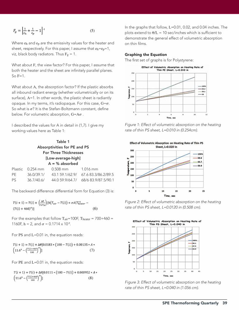
SPE Thermoforming Quarterly 39
Where eh and ep are the emissivity values for the heater and sheet, respectively. For this paper, I assume that eh=ep=1, viz, black body radiators. Thus Fg = 1.
What about F, the view factor? For this paper, I assume that both the heater and the sheet are infinitely parallel planes. So F=1.
What about A, the absorption factor? If the plastic absorbs all inbound radiant energy (whether volumetrically or on its surface), A=1. In other words, the plastic sheet is radiantly opaque. In my terms, it’s radiopaque. For this case, G=. So what is ? It is the Stefan-Boltzmann constant, define below. For volumetric absorption, G=A .
I described the values for A in detail in (1,7). I give my working values here as Table 1:
Table 1Absorptivities for PE and PS
For Three Thicknesses[Low-average-high]
A = % absorbedPlastic 0.254 mm 0.508 mm 1.016 mmPE 36.0/39.1/ 43.1 59.1/62.9/ 67.6 83.3/86.2/89.5PS 36.7/40.6/ 44.0 59.9/64.7/ 68/6 83.9/87.5/90.1
The backward difference differential form for Equation (3) is:
For the examples that follow Tair=100F, Theater = 700+460 = 1160F, h = 2, and = 0.1714 x 10⁻⁸.
For PS and L=0.01 in, the equation reads:
For PE and L=0.01 in, the equation reads:
In the graphs that follow, L=0.01, 0.02, and 0.04 inches. The plots extend to 0/L = 10 sec/inches which is sufficient to demonstrate the general effect of volumetric absorption on thin films.
Graphing the EquationThe first set of graphs is for Polystyrene:
Figure 1: Effect of volumetric absorption on the heating rate of thin PS sheet, L=0.010 in (0.254cm).
Figure 2: Effect of volumetric absorption on the heating rate of thin PS sheet, L=0.0120 in (0.508 cm).
Figure 3: Effect of volumetric absorption on the heating rate of thin PS sheet, L=0.040 in (1.056 cm).
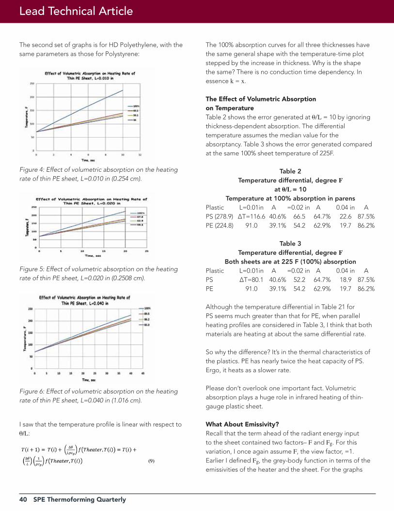
40 SPE Thermoforming Quarterly
The second set of graphs is for HD Polyethylene, with the same parameters as those for Polystyrene:
I saw that the temperature profile is linear with respect to 0/L:
The 100% absorption curves for all three thicknesses have the same general shape with the temperature-time plot stepped by the increase in thickness. Why is the shape the same? There is no conduction time dependency. In essence k = x.
The Effect of Volumetric Absorption on TemperatureTable 2 shows the error generated at 0/L = 10 by ignoring thickness-dependent absorption. The differential temperature assumes the median value for the absorptancy. Table 3 shows the error generated compared at the same 100% sheet temperature of 225F.
Table 2Temperature differential, degree F
at 0/L = 10Temperature at 100% absorption in parens
Plastic L=0.01in A =0.02 in A 0.04 in APS (278.9) ΔT=116.6 40.6% 66.5 64.7% 22.6 87.5%PE (224.8) 91.0 39.1% 54.2 62.9% 19.7 86.2%
Table 3Temperature differential, degree F
Both sheets are at 225 F (100%) absorptionPlastic L=0.01in A =0.02 in A 0.04 in APS ΔT=80.1 40.6% 52.2 64.7% 18.9 87.5%PE 91.0 39.1% 54.2 62.9% 19.7 86.2%
Although the temperature differential in Table 21 for PS seems much greater than that for PE, when parallel heating profiles are considered in Table 3, I think that both materials are heating at about the same differential rate.
So why the difference? It’s in the thermal characteristics of the plastics. PE has nearly twice the heat capacity of PS. Ergo, it heats as a slower rate.
Please don’t overlook one important fact. Volumetric absorption plays a huge role in infrared heating of thin-gauge plastic sheet.
What About Emissivity?Recall that the term ahead of the radiant energy input to the sheet contained two factors– F and Fg. For this variation, I once again assume F, the view factor, =1. Earlier I defined Fg, the grey-body function in terms of the emissivities of the heater and the sheet. For the graphs
Figure 4: Effect of volumetric absorption on the heating rate of thin PE sheet, L=0.010 in (0.254 cm).
Figure 6: Effect of volumetric absorption on the heating rate of thin PE sheet, L=0.040 in (1.016 cm).
Figure 5: Effect of volumetric absorption on the heating rate of thin PE sheet, L=0.020 in (0.2508 cm).
Lead Technical Article
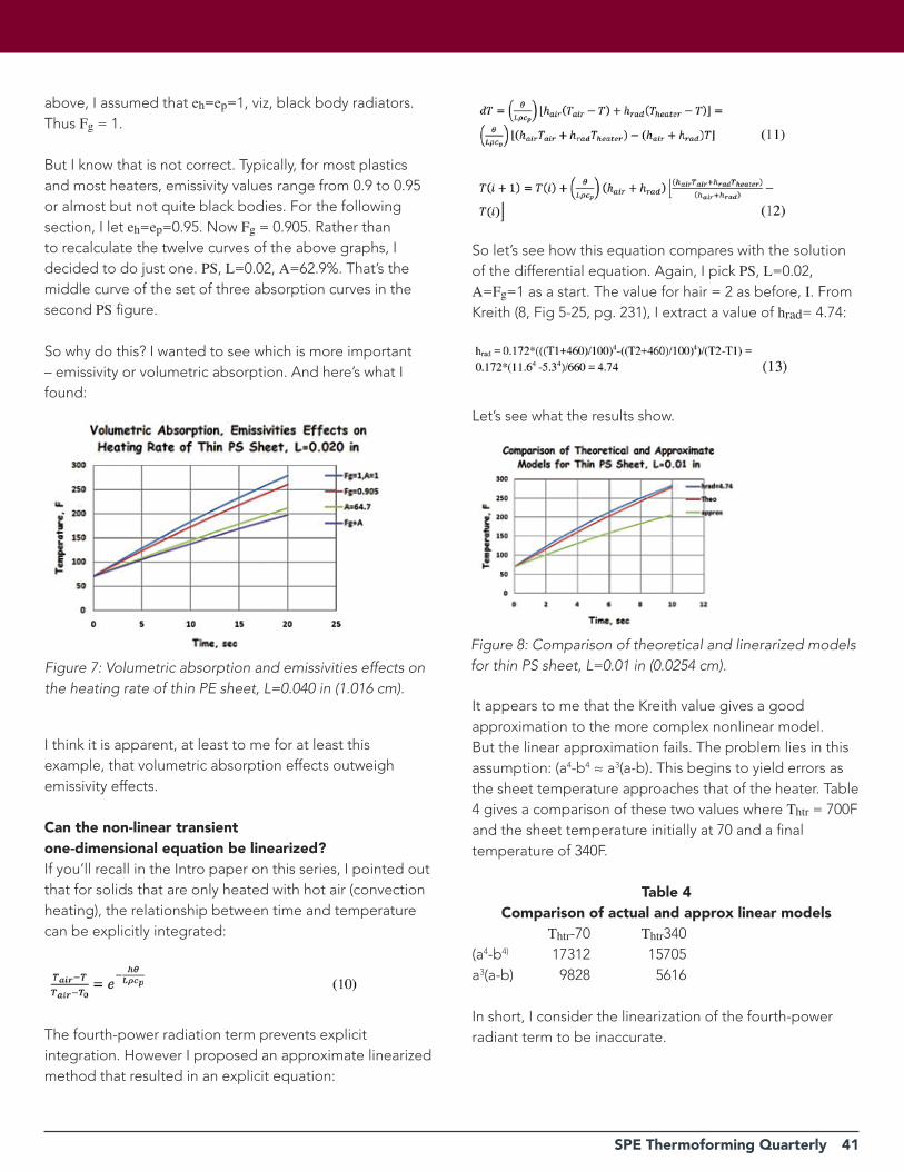
SPE Thermoforming Quarterly 41
above, I assumed that eh=ep=1, viz, black body radiators. Thus Fg = 1.
But I know that is not correct. Typically, for most plastics and most heaters, emissivity values range from 0.9 to 0.95 or almost but not quite black bodies. For the following section, I let eh=ep=0.95. Now Fg = 0.905. Rather than to recalculate the twelve curves of the above graphs, I decided to do just one. PS, L=0.02, A=62.9%. That’s the middle curve of the set of three absorption curves in the second PS figure.
So why do this? I wanted to see which is more important – emissivity or volumetric absorption. And here’s what I found:
I think it is apparent, at least to me for at least this example, that volumetric absorption effects outweigh emissivity effects.
Can the non-linear transient one-dimensional equation be linearized?If you’ll recall in the Intro paper on this series, I pointed out that for solids that are only heated with hot air (convection heating), the relationship between time and temperature can be explicitly integrated:
The fourth-power radiation term prevents explicit integration. However I proposed an approximate linearized method that resulted in an explicit equation:
Figure 7: Volumetric absorption and emissivities effects on the heating rate of thin PE sheet, L=0.040 in (1.016 cm).
So let’s see how this equation compares with the solution of the differential equation. Again, I pick PS, L=0.02, A=Fg=1 as a start. The value for hair = 2 as before, I. From Kreith (8, Fig 5-25, pg. 231), I extract a value of hrad= 4.74:
Let’s see what the results show.
It appears to me that the Kreith value gives a good approximation to the more complex nonlinear model. But the linear approximation fails. The problem lies in this assumption: (a4-b4 ≈ a3(a-b). This begins to yield errors as the sheet temperature approaches that of the heater. Table 4 gives a comparison of these two values where Thtr = 700F and the sheet temperature initially at 70 and a finaltemperature of 340F.
Table 4Comparison of actual and approx linear models
Thtr-70 Thtr340(a4-b4) 17312 15705a3(a-b) 9828 5616
In short, I consider the linearization of the fourth-power radiant term to be inaccurate.
Figure 8: Comparison of theoretical and linerarized models for thin PS sheet, L=0.01 in (0.0254 cm).
42 SPE Thermoforming Quarterly
ConclusionI reason that volumetric absorption in thin plastic sheet, even to the 0.040 in (1.016 cm) thickness plays an important role in determining time-dependent sheet temperature. The effect of volumetric absorption on temperature dominates even the effect of emissivity, particularly at sheetthicknesses of less than 0.020 in (0.508 cm).
And linearizing the fourth-power radiant heating portion of the time-temperature equation does not yield useful results. At least, not in the example I chose.
Table 5General Properties in Equation
references1. J.L. Throne, The Myth of Radiopacity, paper submitted to SPE ANTEC program, May 2016.
2. J.L. Throne, An Improved Algorithm for Determining Energy Interchange between Heaters and Sheet in Thermoforming, paper submitted to SPE ANTEC program, May 2016.
3. J.L. Throne, Processing Thermoformable Low-Density Foam, paper submitted to SPE ANTEC program, May 2016.
4. J. L. Throne, Parametric Radiant Energy Absorption in Plastics, paper submitted to SPE ANTEC program, May 2016.
5. J.L. Throne, Transient Heating of Volumetrically-Absorbing Sheet, paper submitted to SPE ANTEC program, May 2016.
6. J.L. Throne, Interpreting and Applying FTIR Concepts in Thermoforming, paper submitted to SPE ANTEC program, May 2016.
7. J.L. Throne, How Important is the Volumetric Absorption Concept? – Part 1, paper submitted to SPE ANTEC program, May 2016.8. F. Kreith, Principles of Heat Transfer, 2e, International Textbook Company, Scranton, PA, 1958.
9. J.L. Throne, Technology of Thermoforming, Hanser Publishers, Munich, 1996, Section 3.10- View Factor, pp. 152-155.
10. J.L. Throne, Technology of Thermoforming, Hanser Publishers, Munich, 1996, Section 3.11-Thin-Gage Sheet-Approximate Heating rates, pp. 164- 168. |
Lead Technical Article
n
n
n
n
n
n
n
n
n
Follow SPE Thermoforming Division on Twitter!
@SPEThermo
SPE Thermoforming Quarterly 43
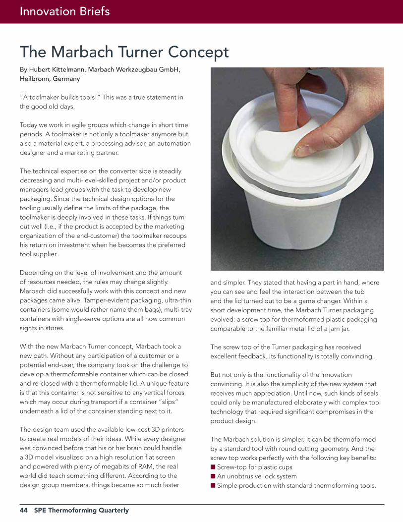
44 SPE Thermoforming Quarterly
Innovation Briefs
The Marbach Turner ConceptBy Hubert Kittelmann, Marbach Werkzeugbau GmbH, Heilbronn, Germany
“A toolmaker builds tools!” This was a true statement in the good old days.
Today we work in agile groups which change in short time periods. A toolmaker is not only a toolmaker anymore but also a material expert, a processing advisor, an automation designer and a marketing partner.
The technical expertise on the converter side is steadily decreasing and multi-level-skilled project and/or product managers lead groups with the task to develop new packaging. Since the technical design options for the tooling usually define the limits of the package, the toolmaker is deeply involved in these tasks. If things turn out well (i.e., if the product is accepted by the marketing organization of the end-customer) the toolmaker recoups his return on investment when he becomes the preferred tool supplier.
Depending on the level of involvement and the amount of resources needed, the rules may change slightly. Marbach did successfully work with this concept and new packages came alive. Tamper-evident packaging, ultra-thin containers (some would rather name them bags), multi-tray containers with single-serve options are all now common sights in stores.
With the new Marbach Turner concept, Marbach took a new path. Without any participation of a customer or a potential end-user, the company took on the challenge to develop a thermoformable container which can be closed and re-closed with a thermoformable lid. A unique feature is that this container is not sensitive to any vertical forces which may occur during transport if a container “slips” underneath a lid of the container standing next to it.
The design team used the available low-cost 3D printers to create real models of their ideas. While every designer was convinced before that his or her brain could handle a 3D model visualized on a high resolution flat screen and powered with plenty of megabits of RAM, the real world did teach something different. According to the design group members, things became so much faster
and simpler. They stated that having a part in hand, where you can see and feel the interaction between the tub and the lid turned out to be a game changer. Within a short development time, the Marbach Turner packaging evolved: a screw top for thermoformed plastic packaging comparable to the familiar metal lid of a jam jar.
The screw top of the Turner packaging has received excellent feedback. Its functionality is totally convincing.
But not only is the functionality of the innovation convincing. It is also the simplicity of the new system that receives much appreciation. Until now, such kinds of seals could only be manufactured elaborately with complex tool technology that required significant compromises in the product design.
The Marbach solution is simpler. It can be thermoformed by a standard tool with round cutting geometry. And the screw top works perfectly with the following key benefits:n Screw-top for plastic cups n An unobtrusive lock system n Simple production with standard thermoforming tools.
SPE Thermoforming Quarterly 45
The Turner was shown as a prototype design model at the K-show in Düsseldorf. At Interpack 2017, the first customer to adapt the model, RPC Bebo Group, showed real samples in PP.
Today, applications which go beyond the original design are under development. Leak resistance and tamper evidence are high on the customer’s wish-list. Medical application users want the package to be child proof. Some want it to be senior-friendly.
Samples need to be made in different materials, colors, and various decoration formats including digital printing, shrink sleeve, and in-mold labeling option IML-T. Having
a proven concept is only phase one; at the end of the day, the customer has to “buy in”.
The European patent has been approved and several international applications are in process. Getting a patent is not a success by itself, however (it actually is a cost factor); nor is winning fancy prizes at packaging shows. We are back to the beginning: “A toolmaker builds tools”. Nevertheless, innovations do have some value in themselves. Many technical features developed in such a process can be applied to the daily business and can have positive impact on the performance and cost of traditional molds. The user may not even be aware from where the added value came. |
Plan now to attend the 26th Annual Thermoforming ConferenceSEPTEMBEr 11-13 IN OrLANDO, FL
The SPE Thermoforming Division invites you to attend its 26th Annual Conference created exclusively by and for the Thermoforming Industry. The Conference will be held at the Renaissance Orlando at SeaWorld, located at 6677 Sea Harbor Drive in Orlando, Florida, 32821.
Network with clients, vendors and industry leaders in one convenient location! Our exhibit hall will provide you with opportunities to meet with equipment, material, tooling and service providers. The SPE Thermoforming Conference® is the most convenient and cost-effective way to learn about the Industry.
Workshops and SessionsFull-day workshops focusing on fundamentals and troubleshooting will help your technical staff gain practical insight into the thermoforming process. Our comprehensive conference program includes technical presentations by recognized industry experts, featuring new and exciting developments in our industry. Attend your choice of presentations delivered by your peers!
Sponsors and ExhibitorsThe Conference is the premier forum where the newest techniques and the latest trends in machinery, materials and equipment are unveiled. View the 2017 Conference list of sponsors and exhibitors here.
Parts CompetitionThe Parts Competition showcases the latest advances in thermoforming design and application. Multiple submission and award categories in roll-fed and cut-sheet deliver unparalleled marketing exposure to conference attendees and the press. Winning parts benefit from full coverage on the Division’s website and in SPE Thermoforming Quarterly® magazine and are usually featured in leading industry magazines. Learn more about the Parts Competition here.
Thermoforming Awards DinnerDuring the Awards Dinner, we will honor the 2017 Thermoformer of the Year Award honoree as well as prior recipients for their contributions to our industry. Winners of the Parts Competition will be announced during the evening as well.
register online today at thermoformingdivision.com/conference
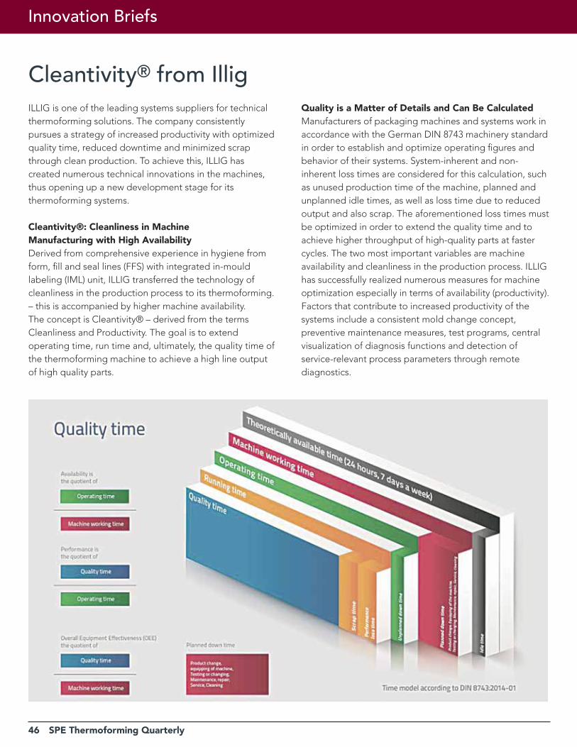
46 SPE Thermoforming Quarterly
Innovation Briefs
Cleantivity® from IlligILLIG is one of the leading systems suppliers for technical thermoforming solutions. The company consistently pursues a strategy of increased productivity with optimized quality time, reduced downtime and minimized scrap through clean production. To achieve this, ILLIG has created numerous technical innovations in the machines, thus opening up a new development stage for its thermoforming systems.
Cleantivity®: Cleanliness in Machine Manufacturing with High AvailabilityDerived from comprehensive experience in hygiene from form, fill and seal lines (FFS) with integrated in-mould labeling (IML) unit, ILLIG transferred the technology of cleanliness in the production process to its thermoforming. – this is accompanied by higher machine availability. The concept is Cleantivity® – derived from the terms Cleanliness and Productivity. The goal is to extend operating time, run time and, ultimately, the quality time of the thermoforming machine to achieve a high line output of high quality parts.
Quality is a Matter of Details and Can Be CalculatedManufacturers of packaging machines and systems work in accordance with the German DIN 8743 machinery standard in order to establish and optimize operating figures and behavior of their systems. System-inherent and non-inherent loss times are considered for this calculation, such as unused production time of the machine, planned and unplanned idle times, as well as loss time due to reduced output and also scrap. The aforementioned loss times must be optimized in order to extend the quality time and to achieve higher throughput of high-quality parts at faster cycles. The two most important variables are machine availability and cleanliness in the production process. ILLIG has successfully realized numerous measures for machine optimization especially in terms of availability (productivity). Factors that contribute to increased productivity of the systems include a consistent mold change concept, preventive maintenance measures, test programs, central visualization of diagnosis functions and detection of service-relevant process parameters through remote diagnostics.
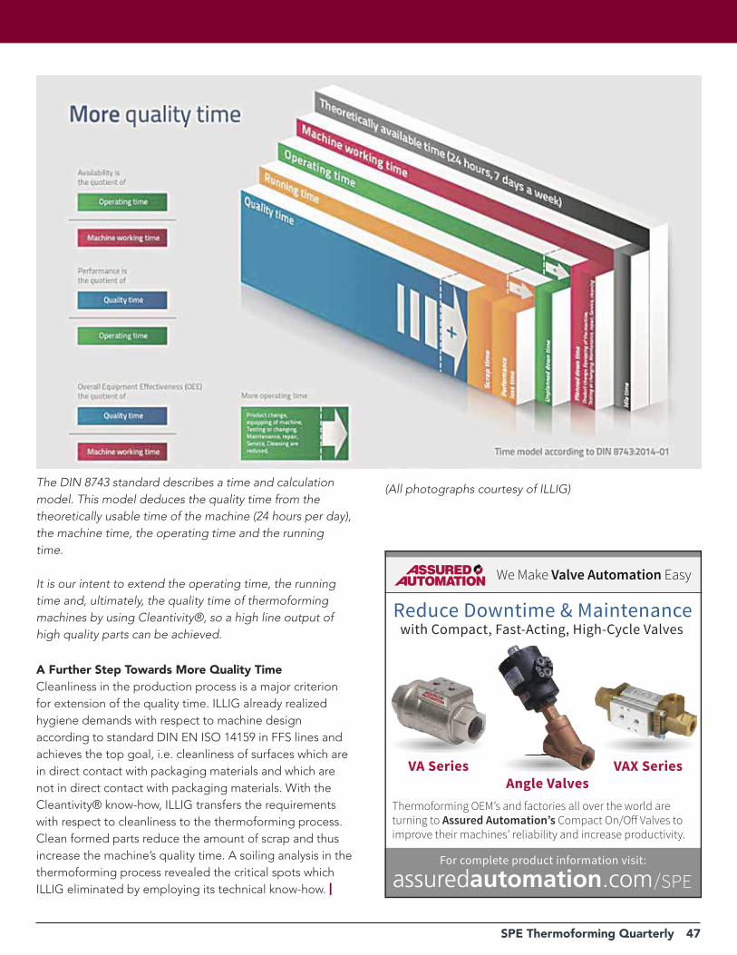
SPE Thermoforming Quarterly 47
A Further Step Towards More Quality TimeCleanliness in the production process is a major criterion for extension of the quality time. ILLIG already realized hygiene demands with respect to machine design according to standard DIN EN ISO 14159 in FFS lines and achieves the top goal, i.e. cleanliness of surfaces which are in direct contact with packaging materials and which are not in direct contact with packaging materials. With the Cleantivity® know-how, ILLIG transfers the requirements with respect to cleanliness to the thermoforming process. Clean formed parts reduce the amount of scrap and thus increase the machine’s quality time. A soiling analysis in the thermoforming process revealed the critical spots which ILLIG eliminated by employing its technical know-how. |
The DIN 8743 standard describes a time and calculation model. This model deduces the quality time from the theoretically usable time of the machine (24 hours per day), the machine time, the operating time and the running time.
It is our intent to extend the operating time, the running time and, ultimately, the quality time of thermoforming machines by using Cleantivity®, so a high line output of high quality parts can be achieved.
(All photographs courtesy of ILLIG)
We Make Valve Automation Easy
Reduce Downtime & Maintenancewith Compact, Fast-Acting, High-Cycle Valves
Thermoforming OEM’s and factories all over the world areturning to Assured Automation’s Compact On/O� Valves toimprove their machines’ reliability and increase productivity.
For complete product information visit:
VA SeriesAngle Valves
VAX Series
/SPE
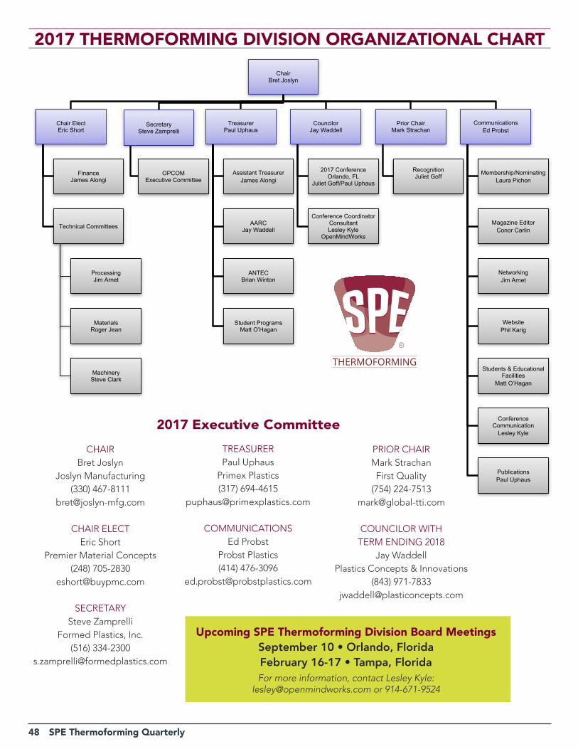
48 SPE Thermoforming Quarterly
ChairBret Joslyn
Chair ElectEric Short
FinanceJames Alongi
Technical Committees
ProcessingJim Arnet
MaterialsRoger Jean
MachinerySteve Clark
SecretarySteve Zamprelli
OPCOMExecutive Committee
TreasurerPaul Uphaus
Assistant TreasurerJames Alongi
AARCJay Waddell
ANTECBrian Winton
Student ProgramsMatt O’Hagan
CouncilorJay Waddell
2017 Conference Orlando, FL
Juliet Goff/Paul Uphaus
Conference CoordinatorConsultantLesley Kyle
OpenMindWorks
Prior ChairMark Strachan
RecognitionJuliet Goff
CommunicationsEd Probst
Membership/NominatingLaura Pichon
Magazine EditorConor Carlin
NetworkingJim Arnet
WebsitePhil Karig
Students & Educational Facilities
Matt O’Hagan
Conference CommunicationLesley Kyle
PublicationsPaul Uphaus
2017 THErMOFOrMING DIVISION OrGANIZATIONAL CHArT
Upcoming SPE Thermoforming Division Board MeetingsSeptember 10 • Orlando, FloridaFebruary 16-17 • Tampa, FloridaFor more information, contact Lesley Kyle:
[email protected] or 914-671-9524
CHAIRBret Joslyn
Joslyn Manufacturing(330) 467-8111
CHAIR ELECTEric Short
Premier Material Concepts(248) 705-2830
SECRETARYSteve Zamprelli
Formed Plastics, Inc.(516) 334-2300
TREASURERPaul Uphaus
Primex Plastics(317) 694-4615
COMMUNICATIONSEd Probst
Probst Plastics(414) 476-3096
2017 Executive Committee
PRIOR CHAIRMark StrachanFirst Quality
(754) [email protected]
COUNCILOR WITH TERM ENDING 2018
Jay WaddellPlastics Concepts & Innovations
(843) [email protected]
SPE Thermoforming Quarterly 49
MACHINERY COMMITTEEJames AlongiMAAC Machinery590 Tower Blvd.Carol Stream, IL 60188T: 630.665.1700F: [email protected]
Steven Clark (Chair)Monark EquipmentPO Box 3354533 S. Garfield RoadAuburn, MI 48611T: 989.662.7250F: [email protected]
Brian GoldenSencorpWhite400 Kidd’s Hill RoadHyannis, MA 02601T: [email protected]
Travis KiefferPlastics Unlimited, Inc.303 1st St. N.W.Preston, IA 52069T: [email protected]
Brian WintonLyle Industries, Inc.4144 W. Lyle RoadBeaverton, MI 48612T: 989.435.7714 x 32F: [email protected]
MATERIALS COMMITTEEJim ArmorArmor & Associates16181 Santa Barbara LaneHuntington Beach, CA 92649T: 714.846.7000F: [email protected]
Juliet GoffKal Plastics2050 East 48th StreetVernon, CA 90058-2022T: [email protected]
Roger P. Jean (Chair)Rowmark/PMCPO Box 16052040 Industrial DriveFindlay, OH 45840T: [email protected]
Phillip KarigMathelin Bay Associates LLC11939 Manchester Road #148Saint Louis, MO 63131T: [email protected]
Ian MunnochMSA Components, Inc.5662 E. St. Rd. 54Bloomfield, IN 47424T: [email protected]
Matt O’HaganLyondellBasell7674 Park Meadow LaneWest Bloomfield, MI 48324T: [email protected]
Laura PichonEx-Tech PlasticsPO Box 57611413 Burlington RoadRichmond, IL 60071T: 847.829.8124F: [email protected]
Ed ProbstProbst Plastics ConsultingP.O. Box 26365Wauwatosa, WI 53226T: [email protected]
Eric ShortPremier Material Concepts11165 Horton RoadHolly, Michigan 48442T: [email protected]
Paul UphausPrimex Plastics4164 Lake Oconee DriveBuford, GA 30519T: 1.800.935.9272F: [email protected]
PROCESSING COMMITTEEJim Arnet (Chair)Hagans Plastics Co.121 W. Rock Island RoadGrand Prairie, TX 75050T: [email protected]
Robert BrowningMcConnell CompanyP.O. Box 450633Atlanta, GA 31145T: 770.939.4497F: [email protected]
Evan GilhamProductive Plastics103 W. Park DriveMt. Laurel, NJ 08054T: 856-778-4300, [email protected]
Ken GriepPortage Casting & Mold2901 Portage RoadPortage, WI 53901T: 608.742.7137F: [email protected]
Bret JoslynJoslyn Manufacturing9400 Valley View RoadMacedonia, OH 44056T: 330.467.8111F: [email protected]
Stephen MurrillProfile Plastics65 S. WaukeganLake Bluff, IL 60044T: 847.604.5100 x29F: [email protected]
Mark StrachanFirst QualityT: [email protected]
Jay WaddellPlastics Concepts & Innovations1127 Queensborough RoadSuite 102Mt. Pleasant, SC 29464T: 843.971.7833F: [email protected]
Steve ZamprelliFormed Plastics, Inc.297 Stonehinge LaneCarle Place, NY 11514T: [email protected]
DIRECTORS EMERITIArt BuckelMcConnell Company3452 Bayonne DriveSan Diego, CA 92109T: [email protected]
Lola Carere302 Sable Trace Ct.Acworth, GA 30102-7617T: [email protected]
Richard FreemanFreetech Plastics Inc.2211 Warm Springs CourtFremont, CA 94539T: [email protected]
Steve HasselbachCMI Plastics222 Pepsi WayAyden, NC 28513T: 252.746.2171F: [email protected]
Donald HyltonMcConnell Company646 Holyfield HighwayFairburn, GA 30213T: [email protected]
Roger KippRoger C. Kipp Consulting3C Owens Landing CourtPerryville, MD 21903T: [email protected]
Gwen Mathis6 S. Second Street SELindale, GA 30147T: [email protected]
Stan Rosen10209 Button Willow DriveLas Vegas, NV 89134T: [email protected]
Board of Directors
50 SPE Thermoforming Quarterly
n Advanced Extruder Technologies ................................ 43
n Assured Automation ...................................................... 47
n Brown Machinery ................................ Inside Front Cover
n CMT Materials .................................................................. 5
n Formed Plastics .............................................................. 42
n GN Thermoforming Equipment ..................................... 9
n Illig ........................................................ Inside Back Cover
n Irwin Research & Development .................................... 13
n MAAC Machinery ........................................................... 25
n O.M.G. SRL ..................................................................... 15
n Portage Casting & Mold ............................................... 25
n Premier Material Concepts ........................................... 17
n Profile Plastics. ............................................................... 42
n PTi Extruders ................................................... Back Cover
n Sekisui Polymer Innovations, LLC. ................................ 31
n Senoplast ........................................................................ 29
n Siemens .......................................................................... 11
n Solar Products .................................................................. 8
n Thermoformer Parts Suppliers ........................................ 5
n TSL .................................................................................. 27
n W.R. Sharples Co., Inc. .................................................. 32
These sponsors enable us to publish SPE Thermoforming Quarterly
Sponsor Index
2017SPE Thermoforming Quarterly Author Membership ProgramThe SPE Thermoforming Division invites prospective
authors to contribute articles to its award-winning
publication, SPE Thermoforming Quarterly. As part of our
mission to facilitate the advancement of thermoforming,
we seek to widen our audience and increase our
knowledge base.
Continuing from February 2016, the Division is offering a one-time, complimentary SPE professional membership to prospective authors who are not currently members of the Society of Plastics Engineers and who have not previously written for Thermoforming Quarterly.
Articles must be approved by the editor. Authors should
strive for objectivity and data- or technology-driven articles
that advance the understanding of thermoforming and
related processes. Articles are typically 1,500-2,000 words
in length. High-resolution images (300 dpi minimum) may
be published with the article.
The magazine offers several major categories of articles:
• The Business of Thermoforming • Lead Technical Articles
• Industry Practice • Thermoforming & Sustainability
Future magazine publication date is November 15.
For additional information, please contact:
Conor Carlin, Technical EditorSPE Thermoforming QuarterlyEmail: [email protected]
Lesley Kyle, SponsorshipsSPE Thermoforming QuarterlyEmail: [email protected]
SPE Thermoforming Quarterly 51