Embed Size (px)
Citation preview
�
CONDUCTIX “Insul-8®” Conductor Bar
The new industry standard for crane, monorail, and material handling electrification. Easy to install and maintain. Collector shoes track accurately on V-contact bar. Requires fewer joints and expansion sections than other systems. “Finger-safe” (IP2 rated). Can be mounted for bottom or lateral entry. Heater wire system available for cold climates; black UV resistant cover for outdoor applications.
UL Listed
The ideal conductor bar system for large process cranes and material handling equipment used in mills and other heavy industrial applications. Aluminum body efficiently dissipates heat; stainless steel “V” contact surface for accurate shoe tracking and long wear. Can be mounted for bottom or lateral entry. Heater wire system available for cold climates; black UV resistant cover for outdoor applications.
UL / CSA Listed
SAFELEC 2
Hevi-Bar II
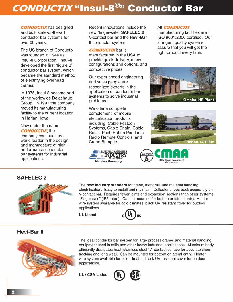
CONDUCTIX has designed and built state-of-the-art conductor bar systems for over 60 years.
The US branch of Conductix was founded in 1944 as Insul-8 Corporation. Insul-8 developed the first “figure 8” conductor bar system, which became the standard method of electrifying overhead cranes.
In 1975, Insul-8 became part of the worldwide Delachaux Group. In 1991 the company moved its manufacturing facility to the current location in Harlan, Iowa.
Now under the name CONDUCTIX, the company continues as a world leader in the design and manufacture of high-performance conductor bar systems for industrial applications.
Recent innovations include the new “finger-safe” SAFELEC 2 V-contact bar and the Hevi-Bar II conductor system.
CONDUCTIX bar is manufactured in the USA to provide quick delivery, many configurations and options, and competitive prices.
Our experienced engineering and sales people are recognized experts in the application of conductor bar systems to solve industrial problems.
We offer a complete complement of mobile electrification products including Cable Festoon Systems, Cable Chain, Cable Reels, Push-Button Pendants, Radio Remote Controls, and Crane Bumpers.
All CONDUCTIX manufacturing facilities are ISO 9001:2000 certified. Our stringent quality systems assure that you will get the right product every time.
Omaha, NE Plant
Harlan, IA Plant
�
Originally developed by Insul-8 over 60 years ago, 8-Bar was the first insulated conductor system for crane/monorail electrification. If you need 8-bar, insist on the original! 8-Bar has many special options and components developed over 60 years of applications. The basic system is designed for bottom entry. A unique Side Contact system is available for lateral mounting. Able to accommodate small bend radii for curved systems and slip rings.
UL / CSA Listed
A compact conductor bar system with 3/4” minimum spacing between bars. For small cranes, material handling applications, and automated storage/retrieval systems. Finger-safe IP2 rating. Able to accommodate small bend radii for curved systems and slip rings. Can be mounted for bottom or lateral entry.
CSA Listed
8-Bar Side Contact
Cluster Bar
If you don’t see what you need, give us a call. We offer thousands of special designs and options!
CONDUCTIX “Insul-8®” Conductor Bar
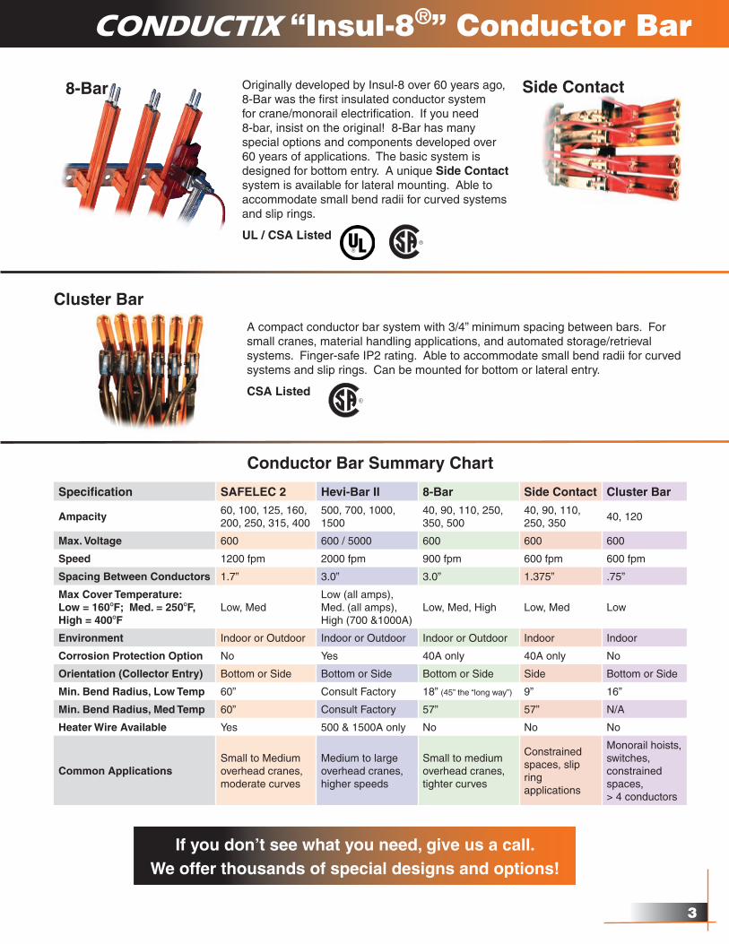
Conductor Bar Summary Chart
Specification SAFELEC 2 Hevi-Bar II 8-Bar Side Contact Cluster Bar
Ampacity60, 100, 125, 160, 200, 250, 315, 400
500, 700, 1000,1500
40, 90, 110, 250, 350, 500
40, 90, 110, 250, 350
40, 120
Max. Voltage 600 600 / 5000 600 600 600
Speed 1200 fpm 2000 fpm 900 fpm 600 fpm 600 fpm
Spacing Between Conductors 1.7” 3.0” 3.0” 1.375” .75”
Max Cover Temperature: Low = 160OF; Med. = 250OF, High = 400OF
Low, MedLow (all amps),Med. (all amps), High (700 &1000A)
Low, Med, High Low, Med Low
Environment Indoor or Outdoor Indoor or Outdoor Indoor or Outdoor Indoor Indoor
Corrosion Protection Option No Yes 40A only 40A only No
Orientation (Collector Entry) Bottom or Side Bottom or Side Bottom or Side Side Bottom or Side
Min. Bend Radius, Low Temp 60” Consult Factory 18” (45” the “long way”) 9” 16”
Min. Bend Radius, Med Temp 60” Consult Factory 57” 57” N/A
Heater Wire Available Yes 500 & 1500A only No No No
Common ApplicationsSmall to Medium overhead cranes, moderate curves
Medium to large overhead cranes, higher speeds
Small to medium overhead cranes, tighter curves
Constrained spaces, slip ring applications
Monorail hoists, switches, constrained spaces, > 4 conductors
�
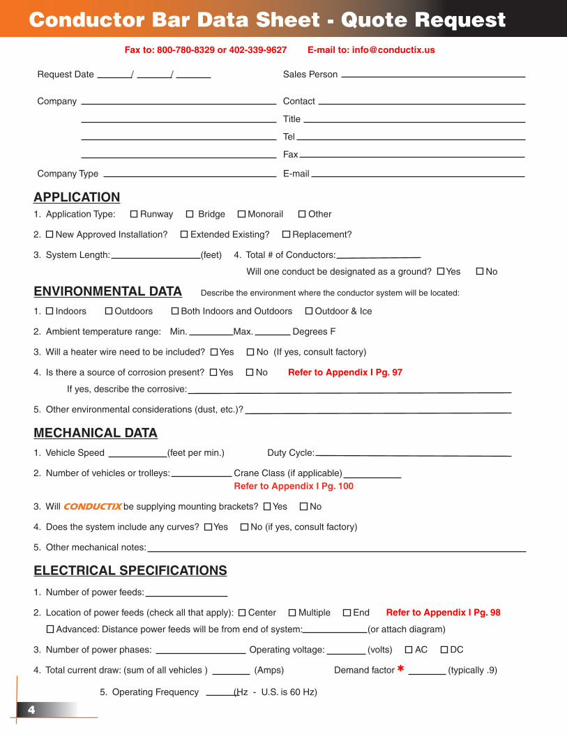
Conductor Bar Data Sheet - Quote Request
Request Date / / Sales Person
Company Contact
Title
Tel
Fax
Company Type E-mail
APPLICATION
ENVIRONMENTAL DATA Describe the environment where the conductor system will be located:
1. Indoors Outdoors Both Indoors and Outdoors Outdoor & Ice
2. Ambient temperature range: Min. Max. Degrees F
3. Will a heater wire need to be included? Yes No (If yes, consult factory)
4. Is there a source of corrosion present? Yes No
If yes, describe the corrosive:
5. Other environmental considerations (dust, etc.)?
1. Application Type: Runway Bridge Monorail Other
2. New Approved Installation? Extended Existing? Replacement?
3. System Length: (feet) 4. Total # of Conductors:
Will one conduct be designated as a ground? Yes No
MECHANICAL DATA
1. Vehicle Speed (feet per min.) Duty Cycle:
2. Number of vehicles or trolleys: Crane Class (if applicable) Refer to Appendix I Pg. 100
3. Will CONDUCTIX be supplying mounting brackets? Yes No
4. Does the system include any curves? Yes No (if yes, consult factory)
5. Other mechanical notes:
5. Operating Frequency (Hz - U.S. is 60 Hz)
ELECTRICAL SPECIFICATIONS
1. Number of power feeds:
2. Location of power feeds (check all that apply): Center Multiple End
Advanced: Distance power feeds will be from end of system: (or attach diagram)
3. Number of power phases: Operating voltage: (volts) AC DC
4. Total current draw: (sum of all vehicles ) (Amps) Demand factor Q (typically .9)
Refer to Appendix I Pg. 97
Refer to Appendix I Pg. 98
Fax to: 800-780-8329 or 402-339-9627 E-mail to: [email protected]
�
Conductor Bar Data Sheet - Quote Request
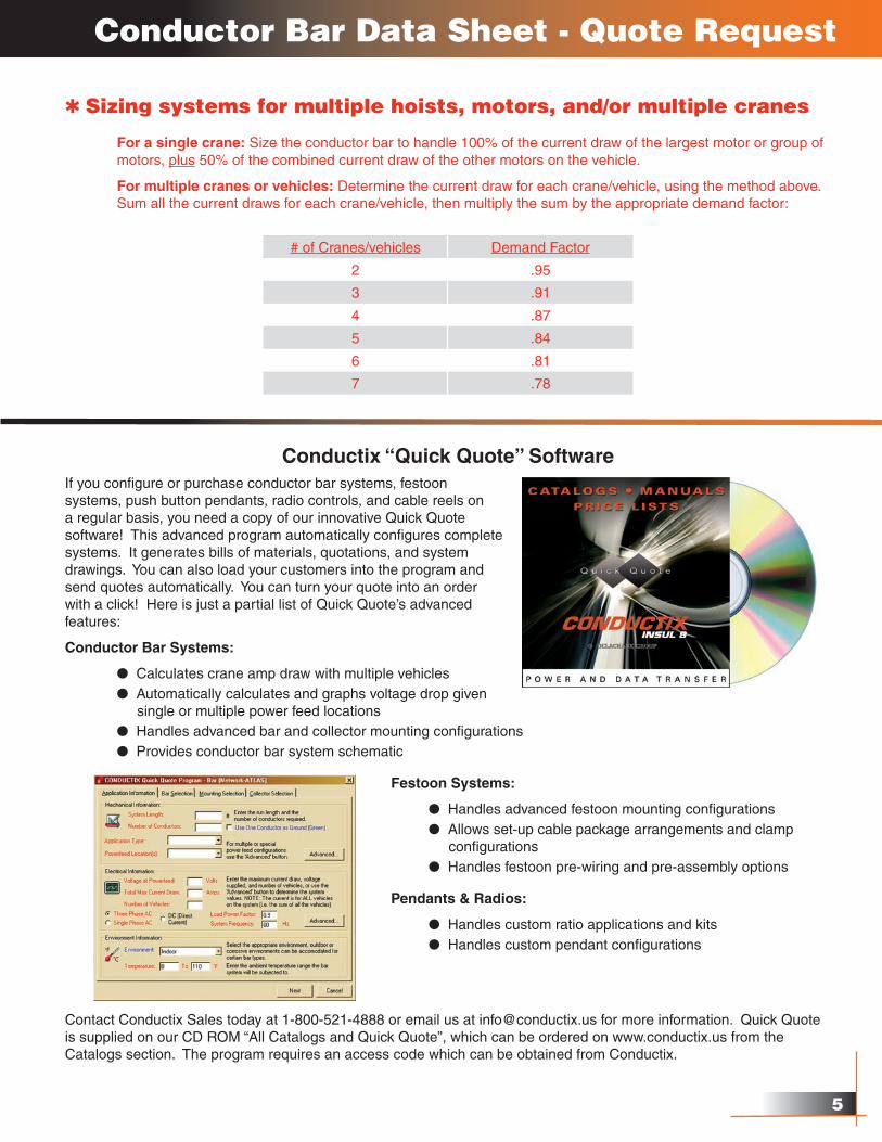
Q Sizing systems for multiple hoists, motors, and/or multiple cranes
For a single crane: Size the conductor bar to handle 100% of the current draw of the largest motor or group of motors, plus 50% of the combined current draw of the other motors on the vehicle.
For multiple cranes or vehicles: Determine the current draw for each crane/vehicle, using the method above. Sum all the current draws for each crane/vehicle, then multiply the sum by the appropriate demand factor:
# of Cranes/vehicles Demand Factor
2 .95
3 .91
4 .87
5 .84
6 .81
7 .78
Conductix “Quick Quote” SoftwareIf you configure or purchase conductor bar systems, festoon systems, push button pendants, radio controls, and cable reels on a regular basis, you need a copy of our innovative Quick Quote software! This advanced program automatically configures complete systems. It generates bills of materials, quotations, and system drawings. You can also load your customers into the program and send quotes automatically. You can turn your quote into an order with a click! Here is just a partial list of Quick Quote’s advanced features:
Conductor Bar Systems:
l Calculates crane amp draw with multiple vehicles l Automatically calculates and graphs voltage drop given single or multiple power feed locations l Handles advanced bar and collector mounting configurations l Provides conductor bar system schematic
Festoon Systems:
l Handles advanced festoon mounting configurations l Allows set-up cable package arrangements and clamp configurations l Handles festoon pre-wiring and pre-assembly options
Pendants & Radios:
l Handles custom ratio applications and kits l Handles custom pendant configurations
Contact Conductix Sales today at 1-800-521-4888 or email us at [email protected] for more information. Quick Quote is supplied on our CD ROM “All Catalogs and Quick Quote”, which can be ordered on www.conductix.us from the Catalogs section. The program requires an access code which can be obtained from Conductix.
�
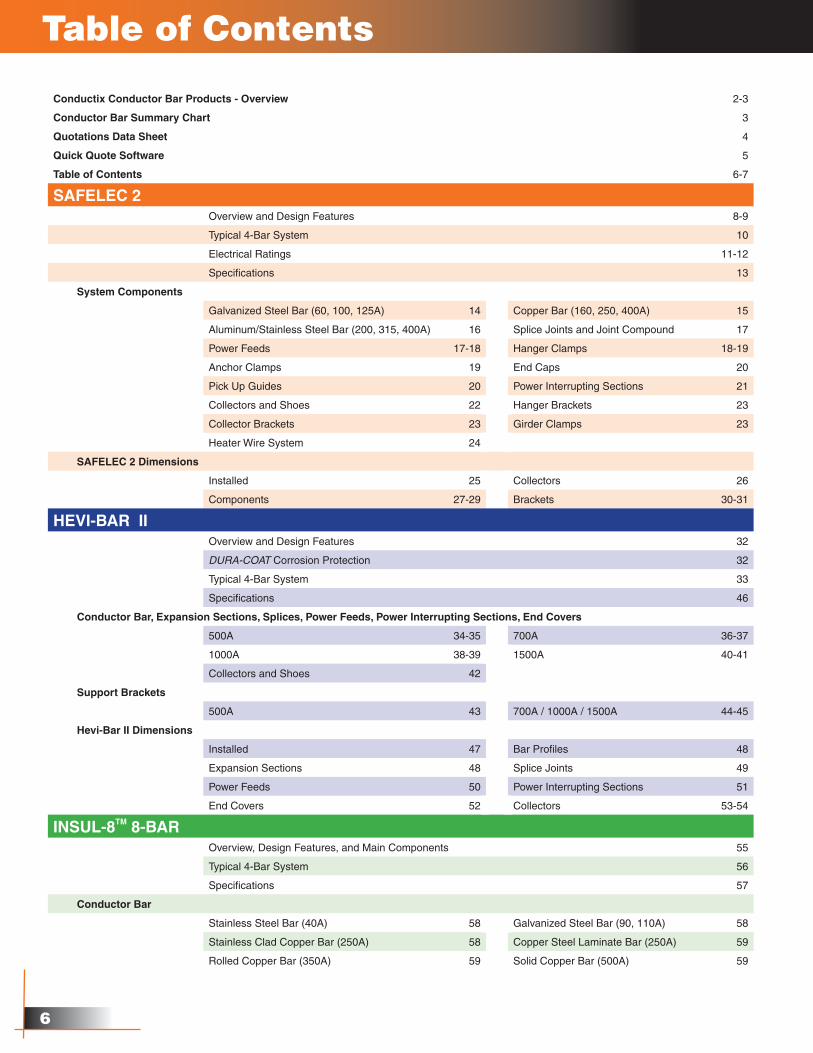
Table of Contents
Conductix Conductor Bar Products - Overview 2-3
Conductor Bar Summary Chart 3
Quotations Data Sheet 4
Quick Quote Software 5
Table of Contents 6-7
SAFELEC 2Overview and Design Features 8-9
Typical 4-Bar System 10
Electrical Ratings 11-12
Specifications 13
System Components
Galvanized Steel Bar (60, 100, 125A) 14 Copper Bar (160, 250, 400A) 15
Aluminum/Stainless Steel Bar (200, 315, 400A) 16 Splice Joints and Joint Compound 17
Power Feeds 17-18 Hanger Clamps 18-19
Anchor Clamps 19 End Caps 20
Pick Up Guides 20 Power Interrupting Sections 21
Collectors and Shoes 22 Hanger Brackets 23
Collector Brackets 23 Girder Clamps 23
Heater Wire System 24
SAFELEC 2 Dimensions
Installed 25 Collectors 26
Components 27-29 Brackets 30-31
HEVI-BAR IIOverview and Design Features 32
DURA-COAT Corrosion Protection 32
Typical 4-Bar System 33
Specifications 46
Conductor Bar, Expansion Sections, Splices, Power Feeds, Power Interrupting Sections, End Covers
500A 34-35 700A 36-37
1000A 38-39 1500A 40-41
Collectors and Shoes 42
Support Brackets
500A 43 700A / 1000A / 1500A 44-45
Hevi-Bar II Dimensions
Installed 47 Bar Profiles 48
Expansion Sections 48 Splice Joints 49
Power Feeds 50 Power Interrupting Sections 51
End Covers 52 Collectors 53-54
INSUL-8TM 8-BAROverview, Design Features, and Main Components 55
Typical 4-Bar System 56
Specifications 57
Conductor Bar
Stainless Steel Bar (40A) 58 Galvanized Steel Bar (90, 110A) 58
Stainless Clad Copper Bar (250A) 58 Copper Steel Laminate Bar (250A) 59
Rolled Copper Bar (350A) 59 Solid Copper Bar (500A) 59
�
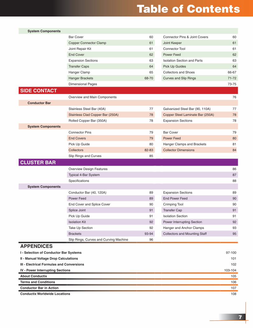
Table of Contents
System Components
Bar Cover 60 Connector Pins & Joint Covers 60
Copper Connector Clamp 61 Joint Keeper 61
Joint Repair Kit 61 Connector Tool 61
End Cover 62 Power Feed 62
Expansion Sections 63 Isolation Section and Parts 63
Transfer Caps 64 Pick Up Guides 64
Hanger Clamp 65 Collectors and Shoes 66-67
Hanger Brackets 68-70 Curves and Slip Rings 71-72
Dimensional Pages 73-75
SIDE CONTACTOverview and Main Components 76
Conductor Bar
Stainless Steel Bar (40A) 77 Galvanized Steel Bar (90, 110A) 77
Stainless Clad Copper Bar (250A) 78 Copper Steel Laminate Bar (250A) 78
Rolled Copper Bar (350A) 78 Expansion Sections 78
System Components
Connector Pins 79 Bar Cover 79
End Covers 79 Power Feed 80
Pick Up Guide 80 Hanger Clamps and Brackets 81
Collectors 82-83 Collector Dimensions 84
Slip Rings and Curves 85
CLUSTER BAROverview Design Features 86
Typical 4-Bar System 87
Specifications 88
System Components
Conductor Bar (40, 120A) 89 Expansion Sections 89
Power Feed 89 End Power Feed 90
End Cover and Splice Cover 90 Crimping Tool 90
Splice Joint 91 Transfer Cap 91
Pick Up Guide 91 Isolation Section 91
Isolation Kit 92 Power Interrupting Section 92
Take Up Section 92 Hanger and Anchor Clamps 93
Brackets 93-94 Collectors and Mounting Staff 95
Slip Rings, Curves and Curving Machine 96
APPENDICESI - Selection of Conductor Bar Systems 97-100
II - Manual Voltage Drop Calculations 101
III - Electrical Formulas and Conversions 102
IV - Power Interrupting Sections 103-104
About Conductix 105
Terms and Conditions 106
Conductor Bar in Action 107
Conductix Worldwide Locations 108
��
8-Bar
Insul-8TM 8-Bar Overview
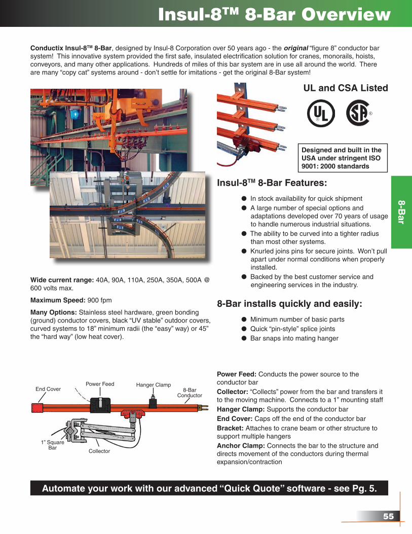
Conductix Insul-8TM 8-Bar, designed by Insul-8 Corporation over 50 years ago - the original “figure 8” conductor bar system! This innovative system provided the first safe, insulated electrification solution for cranes, monorails, hoists, conveyors, and many other applications. Hundreds of miles of this bar system are in use all around the world. There are many “copy cat” systems around - don’t settle for imitations - get the original 8-Bar system!
Designed and built in the USA under stringent ISO 9001: 2000 standards
Insul-8TM 8-Bar Features:
l In stock availability for quick shipment l A large number of special options and adaptations developed over 70 years of usage to handle numerous industrial situations. l The ability to be curved into a tighter radius than most other systems. l Knurled joins pins for secure joints. Won’t pull apart under normal conditions when properly installed. l Backed by the best customer service and engineering services in the industry.
UL and CSA Listed
8-Bar installs quickly and easily:
l Minimum number of basic parts l Quick “pin-style” splice joints l Bar snaps into mating hanger
Wide current range: 40A, 90A, 110A, 250A, 350A, 500A @ 600 volts max.
Maximum Speed: 900 fpm
Many Options: Stainless steel hardware, green bonding (ground) conductor covers, black “UV stable” outdoor covers, curved systems to 18” minimum radii (the “easy” way) or 45” the “hard way” (low heat cover).
Power Feed: Conducts the power source to the conductor barCollector: “Collects” power from the bar and transfers it to the moving machine. Connects to a 1” mounting staffHanger Clamp: Supports the conductor barEnd Cover: Caps off the end of the conductor barBracket: Attaches to crane beam or other structure to support multiple hangersAnchor Clamp: Connects the bar to the structure and directs movement of the conductors during thermal expansion/contraction
End CoverPower Feed Hanger Clamp
8-BarConductor
1” SquareBar
Collector
Automate your work with our advanced “Quick Quote” software - see Pg. 5.
��
8-Bar
8-Bar Typical �-Bar System
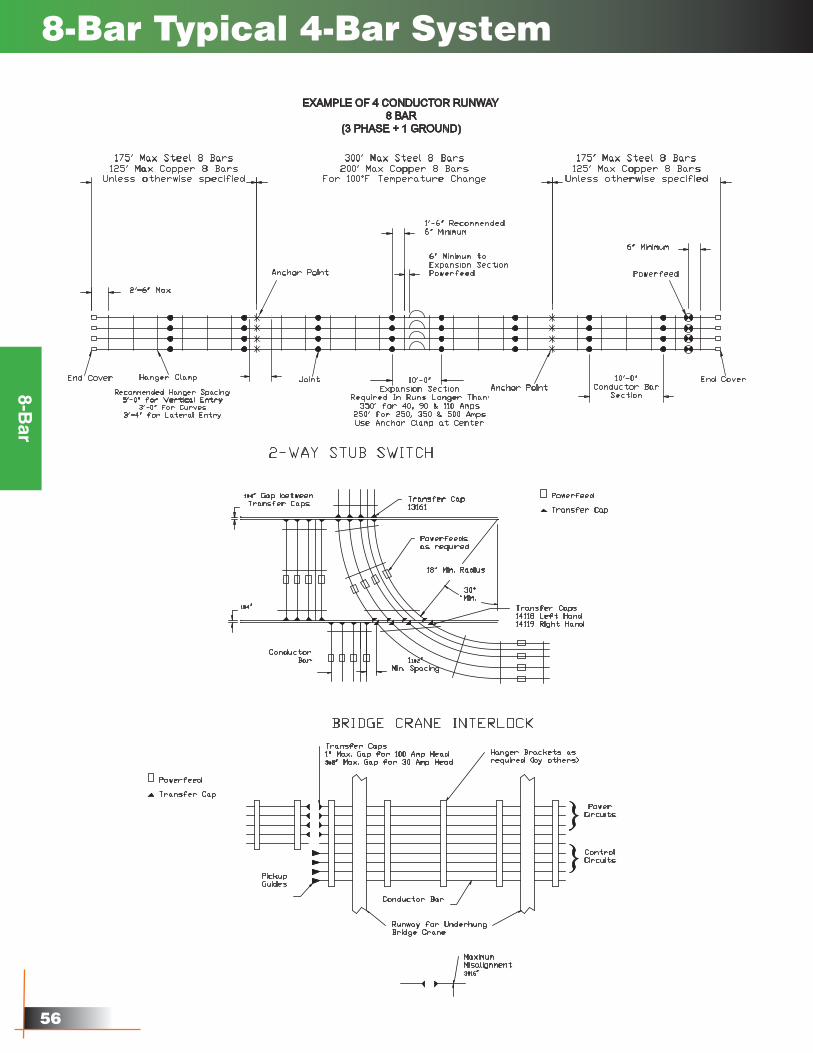
EXAMPLE OF 4 CONDUCTOR RUNWAY8 BAR
(3 PHASE + 1 GROUND)
175' Max Steel 8 Bars125' Max Copper 8 Bars
Unless otherwise specified
175' Max Steel 8 Bars125' Max Copper 8 Bars
Unless otherwise specified
2'-6" Max
End Cover Hanger Clamp
Recommended Hanger Spacing:5'-0" for Vertical Entry
3'-0" for Curves3'-4" for Lateral Entry
Anchor Point
Joint
6" Minimum toExpansion SectionPowerfeed
1'-6" Recommended6" Minimum
Anchor PointEnd Cover
Powerfeed
10'-0"Conductor Bar
Section
10'-0"Expansion Section
Required In Runs Longer Than:350' for 40, 90 & 110 Amps
250' for 250, 350 & 500 AmpsUse Anchor Clamp at Center
300' Max Steel 8 Bars200' Max Copper 8 Bars
For 100°F Temperature Change
6" Minimum
CONDUCTORSPACING
COLLECTORS MOUNTEDSIDE-BY-SIDE
SINGLE COLLECTORSSTAGGERED
Minimum
Recommended
2"
3"
11#2"
2"
11#2"Min. Spacing
ConductorBar
18" Min. Radius
Powerfeedsas required
30°Min.
Powerfeed
Transfer CapTransfer Cap13161
Transfer Caps14118 Left Hand14119 Right Hand
1#4" Gap betweenTransfer Caps
1#4"
2-WAY STUB SWITCHBRIDGE CRANE INTERLOCK
PickupGuides
MaximumMisalignment3#16"
Transfer Caps 1" Max. Gap for 100 Amp Head3#8" Max. Gap for 30 Amp Head
Hanger Brackets asrequired (by others)
Conductor Bar
Runway for UnderhungBridge Crane
}}
PowerCircuits
ControlCircuits
��
8-Bar
8-Bar Specifications
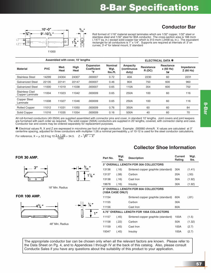
Conductor Bar
Collector Shoe Information
Roll formed of 1/16” material except laminates which are 1/32” copper, 1/32” steel or stainless steel and 1/32” steel for 90A conductor. The cross-section area is 188 mcm (.1477 sq. in.) except solid copper bar which is 313 mcm (.2458 sq. in.). The equivalent rectangle for all conductors is 1” x 1/4”. Supports are required at intervals of: 3’ on curves, 3’-4” for lateral mount, 5’ standard
11000
Assembled with cover, 10’ lengths ELECTRICAL DATA Q
Material PVCMed.Heat
HighHeat
Expansion Coefficient
OF
NominalWgt.
lbs./ft.
Ampacity(continuous
duty)
ResistanceR (DC)
Reactancex (60 Hz)
3o
ImpedanceZ (60 Hz)
Stainless Steel 14299 24304 24307 .000007 0.72 40A 2230 60 2231
Galvanized Steel 22135 22141 22147 .000007 0.46 90A 750 600 960
Galvanized Steel 11000 11019 11038 .000007 0.65 110A 354 600 702
Stainless CladCopper Laminate 11004 11023 11042 .000009 0.65 250A 100 60 116
Copper SteelLaminate
11008 11027 11046 .000009 0.65 250A 100 60 116
Rolled Copper 11012 11031 11050 .000009 0.76 350A 60 60 84
Solid Copper 11016 11035 11054 .000009 0.16 500A 40 60 70
All roll-formed conductors (40-350A) are supplied assembled with connector pins and cover, in standard 10’ lengths. Joint covers and joint keepers are furnished with each order as required. The solid copper (500A) conductors are supplied in 20’ lengths, covered, with connector clamp and case. Conductor bar and covers may be ordered separately for replacement purposes.
Q Electrical values R, X and Z are expressed in microhms per foot of single conductor. Example: .000060 ohms/ft. X values are calculated at 3” centerline spacing, adjusted for three conductors with multiplier 1:26 a nominal permeability m of 10-12 is used for the steel conductor calculations.
For reference, X = m 52.9 log 10 3 x 1.26 + 34.5. Z = R2 1 X3
1250
Part No.Wgt. lbs.
DescriptionCurrentRating
Wgt. lbs.
3” OVERALL LENGTH FOR 30A COLLECTORS
13136 (.16) Sintered copper graphite (standard) 30A (1.41)
13137 (.08) Carbon 20A (.50)
13138 (.16) Cast Iron 30A (1.92)
19678 (.16) Insuloy 30A (1.92)
3” OVERALL LENGTH FOR 60A COLLECTORS (100A CASE ONLY)
11154 Sintered copper graphite (standard) 60A (.81)
11155 Carbon 30A
11156 Cast Iron 60A
4.75” OVERALL LENGTH FOR 100A COLLECTORS
11157 (.45) Sintered copper graphite (standard) 100A (1.5)
11158 (.22) Carbon 50A (1.32)
11159 (.45) Cast Iron 100A (2.7)
19347 (.45) Insuloy 100A (2.7)
The appropriate conductor bar can be chosen only when all the relevant factors are known. Please refer to the Data Sheet on Pg. 4, and to Appendices I through IV at the back of this catalog. Also, please consult Conductix Sales if you have any questions about the suitability of this product to your application.
18” Min. Radius
48” Min. Radius
58
8-Bar
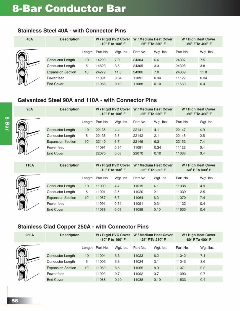
Stainless Clad Copper 250A - with Connector Pins250A Description W / Rigid PVC Cover
-10O F to 160O FW / Medium Heat Cover
-25O F To 250O FW / High Heat Cover
-60O F To 400O F
Length Part No. Wgt. lbs. Part No. Wgt. lbs. Part No. Wgt. lbs.
Conductor Length 10’ 11004 6.6 11023 6.2 11042 7.1
Conductor Length 5’ 11005 3.3 11024 3.1 11043 3.6
Expansion Section 10’ 11059 8.5 11065 8.0 11071 9.2
Power feed 11092 0.7 11092 0.7 11093 0.7
End Cover 11088 0.10 11088 0.10 11633 0.4
8-Bar Conductor Bar
Stainless Steel 40A - with Connector Pins40A Description W / Rigid PVC Cover
-10O F to 160O FW / Medium Heat Cover
-25O F To 250O FW / High Heat Cover
-60O F To 400O F
Length Part No. Wgt. lbs. Part No. Wgt. lbs. Part No. Wgt. lbs.
Conductor Length 10’ 14299 7.0 24304 6.6 24307 7.5
Conductor Length 5’ 14823 3.5 24305 3.3 24308 3.8
Expansion Section 10’ 24279 11.0 24306 7.0 24309 11.8
Power feed 11091 0.34 11091 0.34 11122 0.34
End Cover 11088 0.10 11088 0.10 11633 0.4
Galvanized Steel 90A and 110A - with Connector Pins
90A Description W / Rigid PVC Cover-10O F to 160O F
W / Medium Heat Cover-25O F To 250O F
W / High Heat Cover -60O F To 400O F
Length Part No. Wgt. lbs. Part No. Wgt. lbs. Part No. Wgt. lbs.
Conductor Length 10’ 22135 4.4 22141 4.1 22147 4.9
Conductor Length 5’ 22136 3.5 22142 2.1 22148 2.5
Expansion Section 10’ 22140 6.7 22146 6.3 22152 7.4
Power feed 11091 0.34 11091 0.34 11122 0.4
End Cover 22070 0.03 22070 0.10 11633 0.4
110A Description W / Rigid PVC Cover-10O F to 160O F
W / Medium Heat Cover-25O F To 250O F
W / High Heat Cover -60O F To 400O F
Length Part No. Wgt. lbs. Part No. Wgt. lbs. Part No. Wgt. lbs.
Conductor Length 10’ 11000 4.4 11019 4.1 11038 4.9
Conductor Length 5’ 11001 3.5 11020 2.1 11039 2.5
Expansion Section 10’ 11057 6.7 11064 6.3 11070 7.4
Power feed 11091 0.34 11091 0.34 11122 0.4
End Cover 11088 0.03 11088 0.10 11633 0.4
��
8-Bar
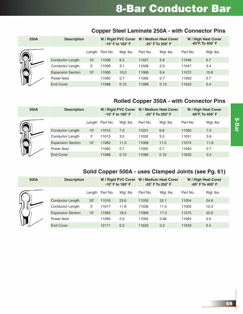
8-Bar Conductor Bar
Copper Steel Laminate 250A - with Connector Pins250A Description W / Rigid PVC Cover
-10O F to 160O FW / Medium Heat Cover
-25O F To 250O FW / High Heat Cover
-60OF. To 400O F
Length Part No. Wgt. lbs. Part No. Wgt. lbs. Part No. Wgt. lbs.
Conductor Length 10’ 11008 6.2 11027 5.8 11046 6.7
Conductor Length 5’ 11009 3.1 11028 2.9 11047 3.4
Expansion Section 10’ 11060 10.0 11066 9.4 11072 10.8
Power feed 11092 0.7 11092 0.7 11093 0.7
End Cover 11088 0.10 11088 0.10 11633 0.4
Rolled Copper 350A - with Connector Pins350A Description W / Rigid PVC Cover
-10O F to 160O FW / Medium Heat Cover
-25O F To 250O FW / High Heat Cover
-60OF. To 400O F
Length Part No. Wgt. lbs. Part No. Wgt. lbs. Part No. Wgt. lbs.
Conductor Length 10’ 11012 7.0 11031 6.6 11050 7.5
Conductor Length 5’ 11013 3.5 11032 3.3 11051 3.8
Expansion Section 10’ 11062 11.0 11068 11.0 11074 11.8
Power feed 11092 0.7 11092 0.7 11093 0.7
End Cover 11088 0.10 11088 0.10 11633 0.4
Solid Copper 500A - uses Clamped Joints (see Pg. 61)500A Description W / Rigid PVC Cover
-10O F to 160O FW / Medium Heat Cover
-25O F To 250O FW / High Heat Cover
-60O F To 400O F
Length Part No. Wgt. lbs. Part No. Wgt. lbs. Part No. Wgt. lbs.
Conductor Length 20’ 11016 23.6 11035 22.1 11054 24.6
Conductor Length 5’ 11017 11.8 11036 11.0 11055 12.3
Expansion Section 10’ 11063 18.5 11069 17.3 11075 20.0
Power feed 11094 2.6 11094 0.66 11094 2.6
End Cover 12171 0.2 11633 0.2 11633 0.4
�0
8-Bar
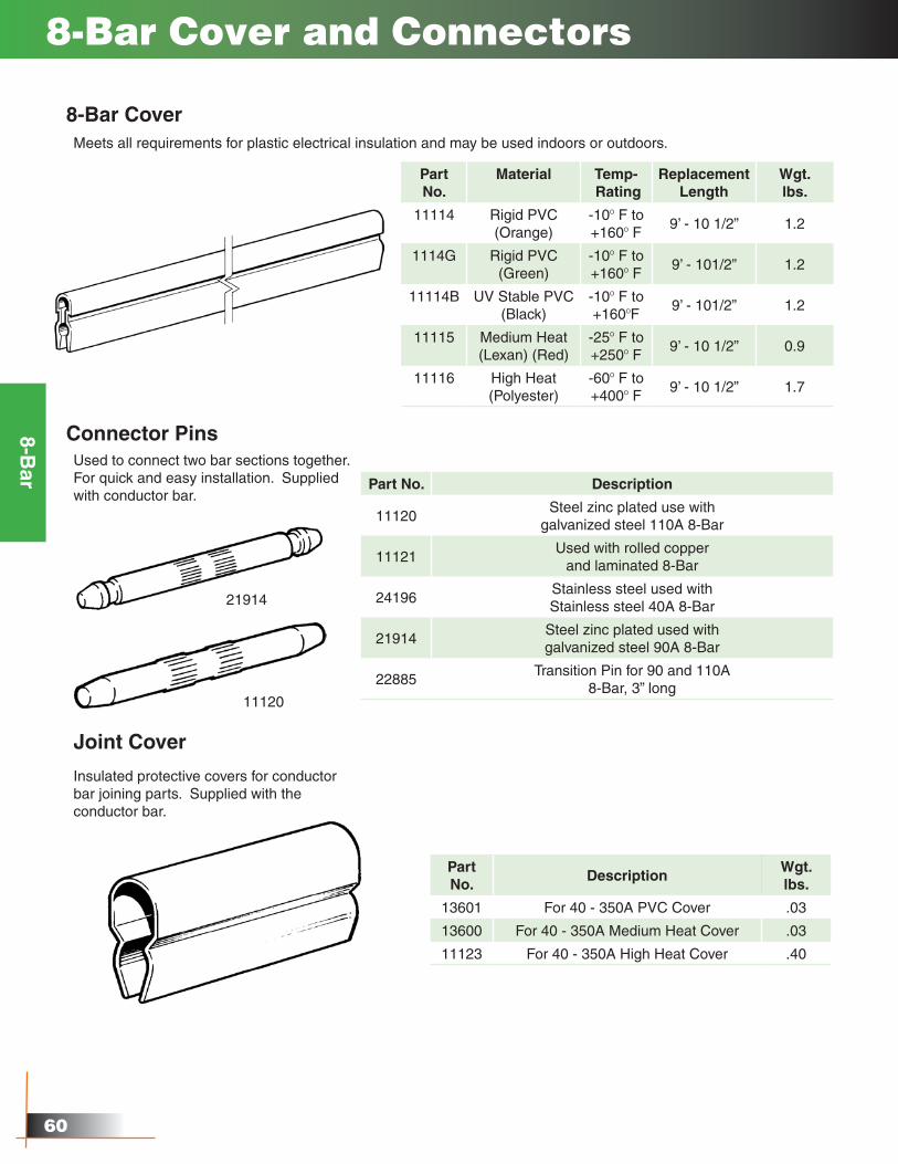
8-Bar Cover and Connectors
8-Bar CoverMeets all requirements for plastic electrical insulation and may be used indoors or outdoors.
Part No.
Material Temp- Rating
Replacement Length
Wgt.lbs.
11114 Rigid PVC(Orange)
-10O F to+160O F
9’ - 10 1/2” 1.2
1114G Rigid PVC(Green)
-10O F to +160O F
9’ - 101/2” 1.2
11114B UV Stable PVC(Black)
-10O F to +160OF
9’ - 101/2” 1.2
11115 Medium Heat(Lexan) (Red)
-25O F to +250O F
9’ - 10 1/2” 0.9
11116 High Heat(Polyester)
-60O F to +400O F
9’ - 10 1/2” 1.7
Connector PinsUsed to connect two bar sections together.For quick and easy installation. Supplied with conductor bar.
Part No. Description
11120Steel zinc plated use with
galvanized steel 110A 8-Bar
11121Used with rolled copper
and laminated 8-Bar
24196Stainless steel used withStainless steel 40A 8-Bar
21914Steel zinc plated used withgalvanized steel 90A 8-Bar
22885Transition Pin for 90 and 110A
8-Bar, 3” long
21914
11120
Joint Cover
Insulated protective covers for conductor bar joining parts. Supplied with the conductor bar.
Part No.
DescriptionWgt.lbs.
13601 For 40 - 350A PVC Cover .03
13600 For 40 - 350A Medium Heat Cover .03
11123 For 40 - 350A High Heat Cover .40
�1
8-Bar
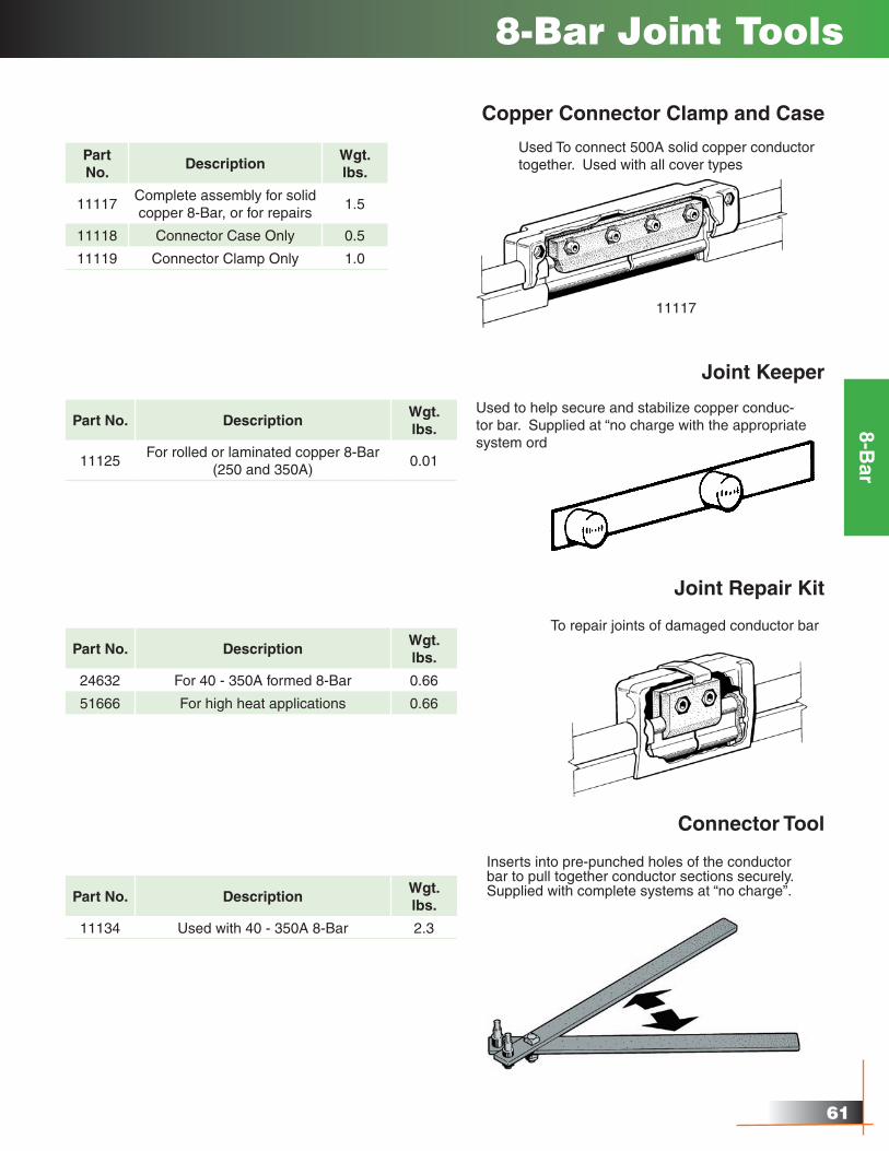
8-Bar Joint Tools
Copper Connector Clamp and Case
Used To connect 500A solid copper conductor together. Used with all cover types
Part No.
DescriptionWgt.lbs.
11117Complete assembly for solid copper 8-Bar, or for repairs
1.5
11118 Connector Case Only 0.5
11119 Connector Clamp Only 1.0
11117
Joint Keeper
Used to help secure and stabilize copper conduc-tor bar. Supplied at “no charge with the appropriate system orders.
Part No. DescriptionWgt. lbs.
11125For rolled or laminated copper 8-Bar
(250 and 350A)0.01
Joint Repair Kit
To repair joints of damaged conductor bar
Part No. DescriptionWgt. lbs.
24632 For 40 - 350A formed 8-Bar 0.66
51666 For high heat applications 0.66
Connector Tool
Part No. DescriptionWgt. lbs.
11134 Used with 40 - 350A 8-Bar 2.3
Inserts into pre-punched holes of the conductor bar to pull together conductor sections securely. Supplied with complete systems at “no charge”.
��
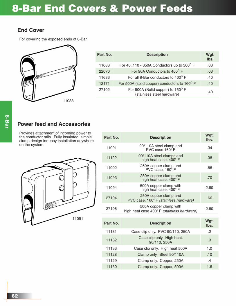
8-Bar End Covers & Power Feeds
For covering the exposed ends of 8-Bar.
Part No. Description Wgt.lbs.
11088 For 40, 110 - 350A Conductors up to 300O F .03
22070 For 90A Conductors to 400O F .03
11633 For all 8-Bar conductors to 400O F .40
12171 For 500A (solid copper) conductors to 160O F .40
27102 For 500A (Solid copper) to 160O F (stainless steel hardware)
.40
11088
End Cover
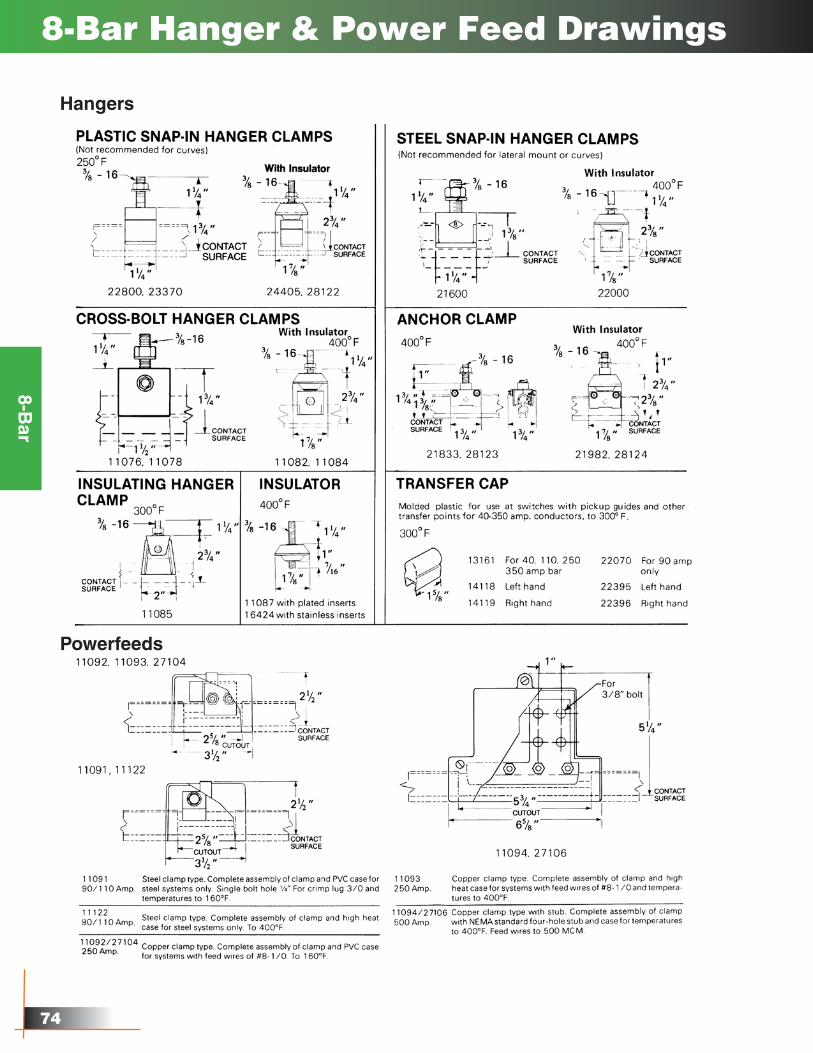
Power feed and Accessories
Provides attachment of incoming power to the conductor rails. Fully insulated, simple clamp design for easy installation anywhere on the system.
Part No. DescriptionWgt. lbs.
11091 90/110A steel clamp and PVC case 160O F .34
11122 90/110A steel clamps andhigh heat case, 400O F .38
11092 250A copper clamp and PVC case, 160O F .66
11093 250A copper clamp andhigh heat case, 400O F .70
11094 500A copper clamp withhigh heat case, 400O F 2.60
27104250A copper clamp and
PVC case, 160O F (stainless hardware).66
27106500A copper clamp with
high heat case 400O F (stainless hardware)2.60
11091Part No. Description
Wgt.lbs.
11131 Case clip only. PVC 90/110, 250A .2
11132Case clip only. High heat.
90/110, 250A.3
11133 Case clip only. High heat 500A 1.0
11128 Clamp only. Steel 90/110A .10
11129 Clamp only. Copper, 250A .4
11130 Clamp only. Copper, 500A 1.6
8-Bar
��
8-Bar
8-Bar Expansions & Isolation Sections
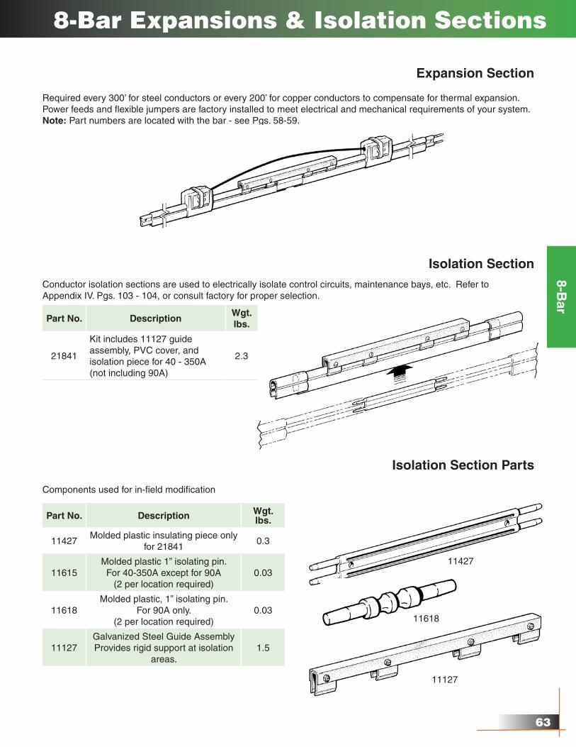
Expansion Section
Required every 300’ for steel conductors or every 200’ for copper conductors to compensate for thermal expansion. Power feeds and flexible jumpers are factory installed to meet electrical and mechanical requirements of your system.Note: Part numbers are located with the bar - see Pgs. 58-59.
Isolation SectionConductor isolation sections are used to electrically isolate control circuits, maintenance bays, etc. Refer to Appendix IV. Pgs. 103 - 104, or consult factory for proper selection.
Isolation Section Parts
Components used for in-field modification
Part No. Description Wgt. lbs.
11427Molded plastic insulating piece only
for 218410.3
11615Molded plastic 1” isolating pin.For 40-350A except for 90A
(2 per location required)0.03
11618Molded plastic, 1” isolating pin.
For 90A only.(2 per location required)
0.03
11127Galvanized Steel Guide AssemblyProvides rigid support at isolation
areas.1.5
11427
11618
Part No. DescriptionWgt.lbs.
21841
Kit includes 11127 guide assembly, PVC cover, and isolation piece for 40 - 350A (not including 90A)
2.3
11127
��
8-Bar
8-Bar Transfer Caps & Pickup Guides
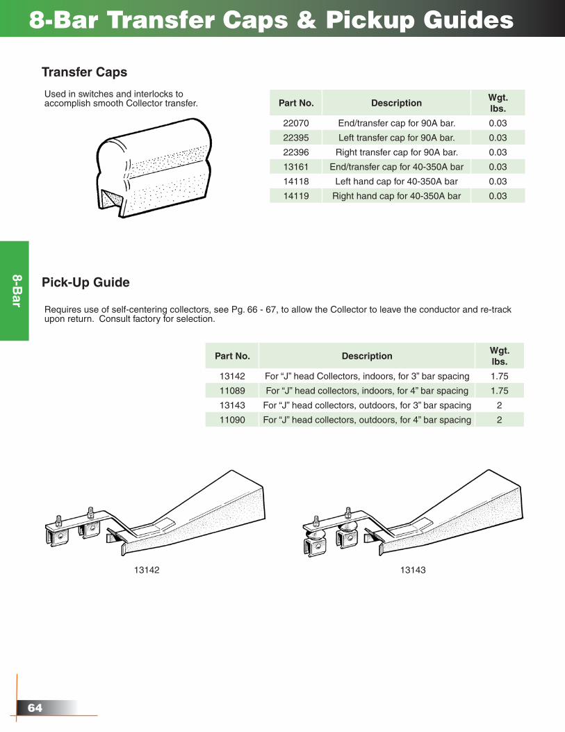
Transfer Caps
Used in switches and interlocks to accomplish smooth Collector transfer. Part No. Description
Wgt.lbs.
22070 End/transfer cap for 90A bar. 0.03
22395 Left transfer cap for 90A bar. 0.03
22396 Right transfer cap for 90A bar. 0.03
13161 End/transfer cap for 40-350A bar 0.03
14118 Left hand cap for 40-350A bar 0.03
14119 Right hand cap for 40-350A bar 0.03
Pick-Up Guide
Requires use of self-centering collectors, see Pg. 66 - 67, to allow the Collector to leave the conductor and re-track upon return. Consult factory for selection.
Part No. DescriptionWgt.lbs.
13142 For “J” head Collectors, indoors, for 3” bar spacing 1.75
11089 For “J” head collectors, indoors, for 4” bar spacing 1.75
13143 For “J” head collectors, outdoors, for 3” bar spacing 2
11090 For “J” head collectors, outdoors, for 4” bar spacing 2
13142 13143
65
8-Bar
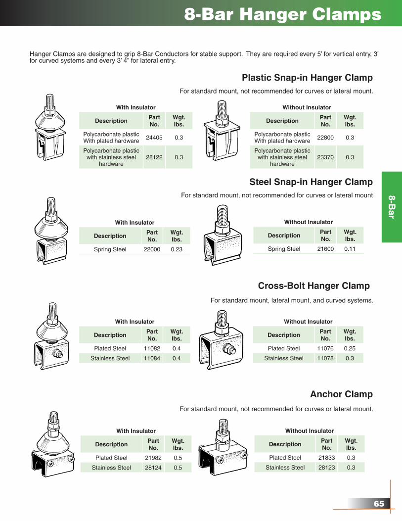
8-Bar Hanger Clamps
Hanger Clamps are designed to grip 8-Bar Conductors for stable support. They are required every 5’ for vertical entry, 3’ for curved systems and every 3’ 4” for lateral entry.
Plastic Snap-in Hanger ClampFor standard mount, not recommended for curves or lateral mount.
With Insulator
DescriptionPart No.
Wgt.lbs.
Polycarbonate plasticWith plated hardware 24405 0.3
Polycarbonate plasticwith stainless steel
hardware28122 0.3
Without Insulator
DescriptionPart No.
Wgt.lbs.
Polycarbonate plasticWith plated hardware 22800 0.3
Polycarbonate plasticwith stainless steel
hardware23370 0.3
Steel Snap-in Hanger ClampFor standard mount, not recommended for curves or lateral mount
With Insulator
DescriptionPart No.
Wgt.lbs.
Spring Steel 22000 0.23
Without Insulator
DescriptionPart No.
Wgt.lbs.
Spring Steel 21600 0.11
Cross-Bolt Hanger Clamp
For standard mount, lateral mount, and curved systems.
With Insulator
DescriptionPart No.
Wgt.lbs.
Plated Steel 11082 0.4
Stainless Steel 11084 0.4
Without Insulator
DescriptionPart No.
Wgt.lbs.
Plated Steel 11076 0.25
Stainless Steel 11078 0.3
Anchor Clamp
For standard mount, not recommended for curves or lateral mount.
With Insulator
DescriptionPart No.
Wgt.lbs.
Plated Steel 21982 0.5
Stainless Steel 28124 0.5
Without Insulator
DescriptionPart No.
Wgt.lbs.
Plated Steel 21833 0.3
Stainless Steel 28123 0.3
��
8-Bar
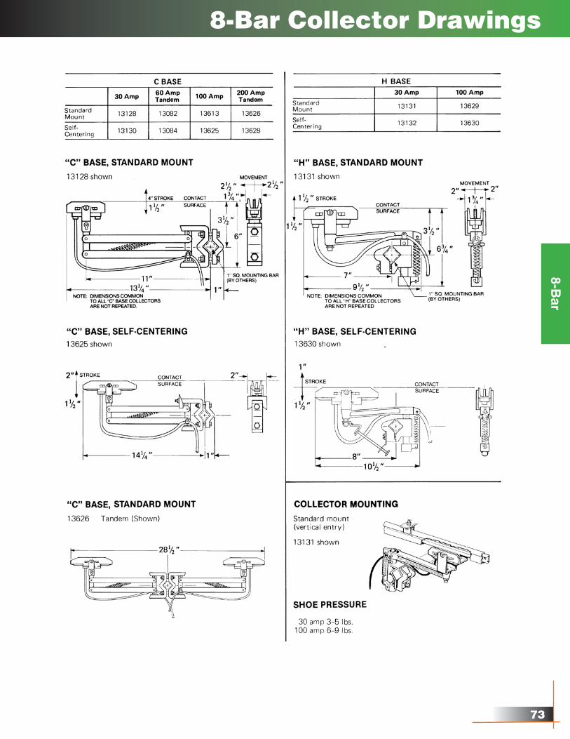
13128
13130
13131
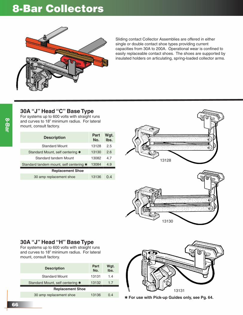
8-Bar Collectors
Sliding contact Collector Assemblies are offered in either single or double contact shoe types providing current capacities from 30A to 200A. Operational wear is confined to easily replaceable contact shoes. The shoes are supported by insulated holders on articulating, spring-loaded collector arms.
30A “J” Head “C” Base TypeFor systems up to 600 volts with straight runs and curves to 18” minimum radius. For lateral mount, consult factory.
DescriptionPart No.
Wgt.lbs.
Standard Mount 13128 2.5
Standard Mount, self centering Q 13130 2.6
Standard tandem Mount 13082 4.7
Standard tandem mount, self centering Q 13084 4.9
Replacement Shoe
30 amp replacement shoe 13136 0.4
DescriptionPart No.
Wgt.lbs.
Standard Mount 13131 1.4
Standard Mount, self centering Q 13132 1.7
Replacement Shoe
30 amp replacement shoe 13136 0.4
30A “J” Head “H” Base TypeFor systems up to 600 volts with straight runs and curves to 18” minimum radius. For lateral mount, consult factory.
Q For use with Pick-up Guides only, see Pg. 64.
��
8-Bar
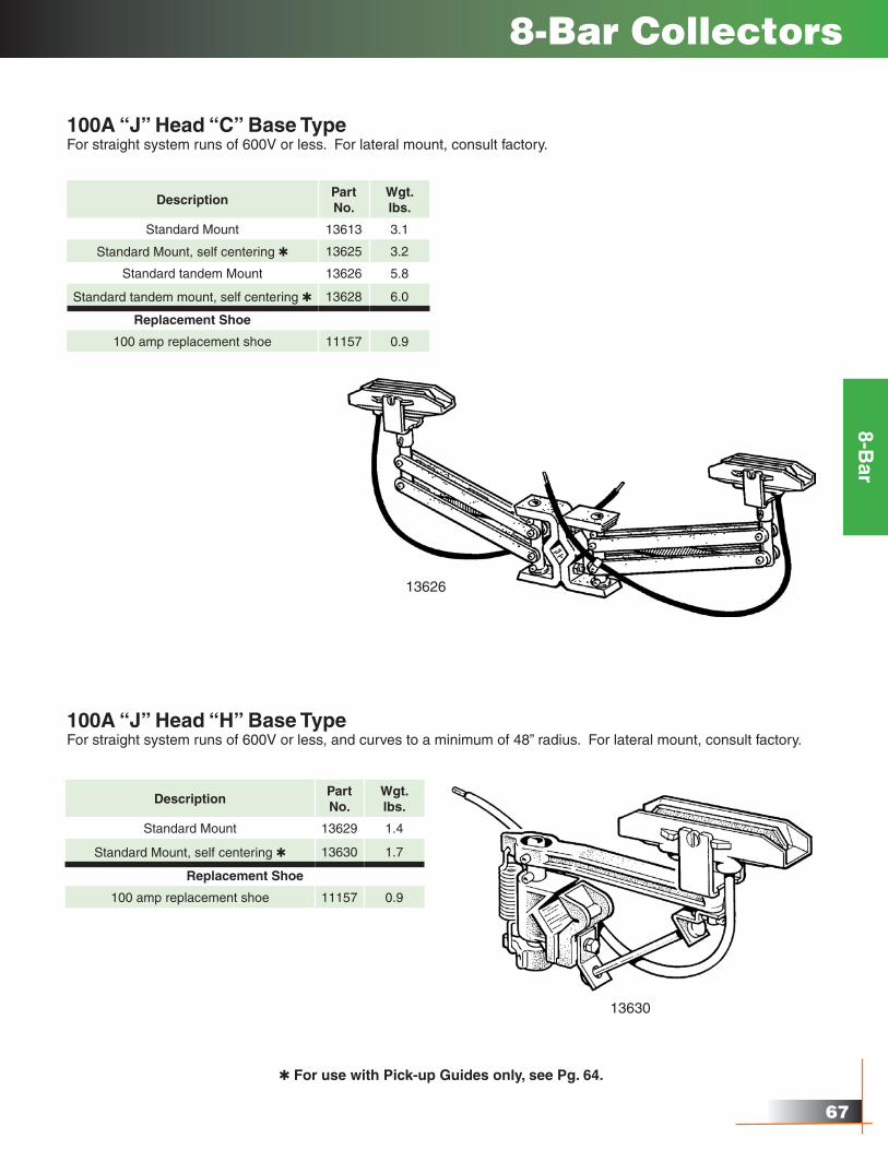
8-Bar Collectors
13626
13630
100A “J” Head “C” Base TypeFor straight system runs of 600V or less. For lateral mount, consult factory.
DescriptionPart No.
Wgt.lbs.
Standard Mount 13613 3.1
Standard Mount, self centering Q 13625 3.2
Standard tandem Mount 13626 5.8
Standard tandem mount, self centering Q 13628 6.0
Replacement Shoe
100 amp replacement shoe 11157 0.9
DescriptionPart No.
Wgt.lbs.
Standard Mount 13629 1.4
Standard Mount, self centering Q 13630 1.7
Replacement Shoe
100 amp replacement shoe 11157 0.9
100A “J” Head “H” Base TypeFor straight system runs of 600V or less, and curves to a minimum of 48” radius. For lateral mount, consult factory.
Q For use with Pick-up Guides only, see Pg. 64.
68
8-Bar
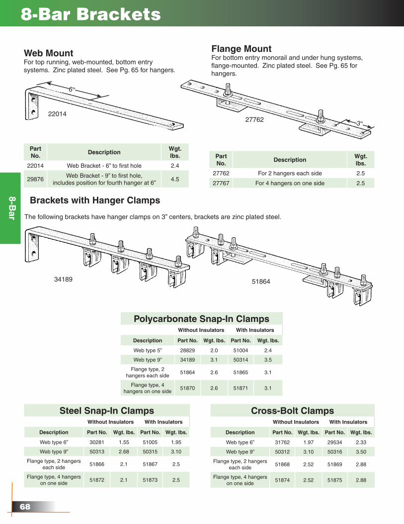
8-Bar Brackets
Web MountFor top running, web-mounted, bottom entry systems. Zinc plated steel. See Pg. 65 for hangers.
Flange MountFor bottom entry monorail and under hung systems, flange-mounted. Zinc plated steel. See Pg. 65 for hangers.
Part No.
DescriptionWgt.lbs.
22014 Web Bracket - 6” to first hole 2.4
29876Web Bracket - 9” to first hole,
includes position for fourth hanger at 6”4.5
Brackets with Hanger Clamps
The following brackets have hanger clamps on 3” centers, brackets are zinc plated steel.
Steel Snap-In ClampsWithout Insulators With Insulators
Description Part No. Wgt. lbs. Part No. Wgt. lbs.
Web type 6” 30281 1.55 51005 1.95
Web type 9” 50313 2.68 50315 3.10
Flange type, 2 hangers each side
51866 2.1 51867 2.5
Flange type, 4 hangers on one side
51872 2.1 51873 2.5
22014
34189 51864
Cross-Bolt ClampsWithout Insulators With Insulators
Description Part No. Wgt. lbs. Part No. Wgt. lbs.
Web type 6” 31762 1.97 29534 2.33
Web type 9” 50312 3.10 50316 3.50
Flange type, 2 hangers each side
51868 2.52 51869 2.88
Flange type, 4 hangers on one side
51874 2.52 51875 2.88
6”
3”
Polycarbonate Snap-In ClampsWithout Insulators With Insulators
Description Part No. Wgt. lbs. Part No. Wgt. lbs.
Web type 5” 28829 2.0 51004 2.4
Web type 9” 34189 3.1 50314 3.5
Flange type, 2 hangers each side
51864 2.6 51865 3.1
Flange type, 4hangers on one side
51870 2.6 51871 3.1
27762
Part No.
DescriptionWgt.lbs.
27762 For 2 hangers each side 2.5
27767 For 4 hangers on one side 2.5
��
8-Bar
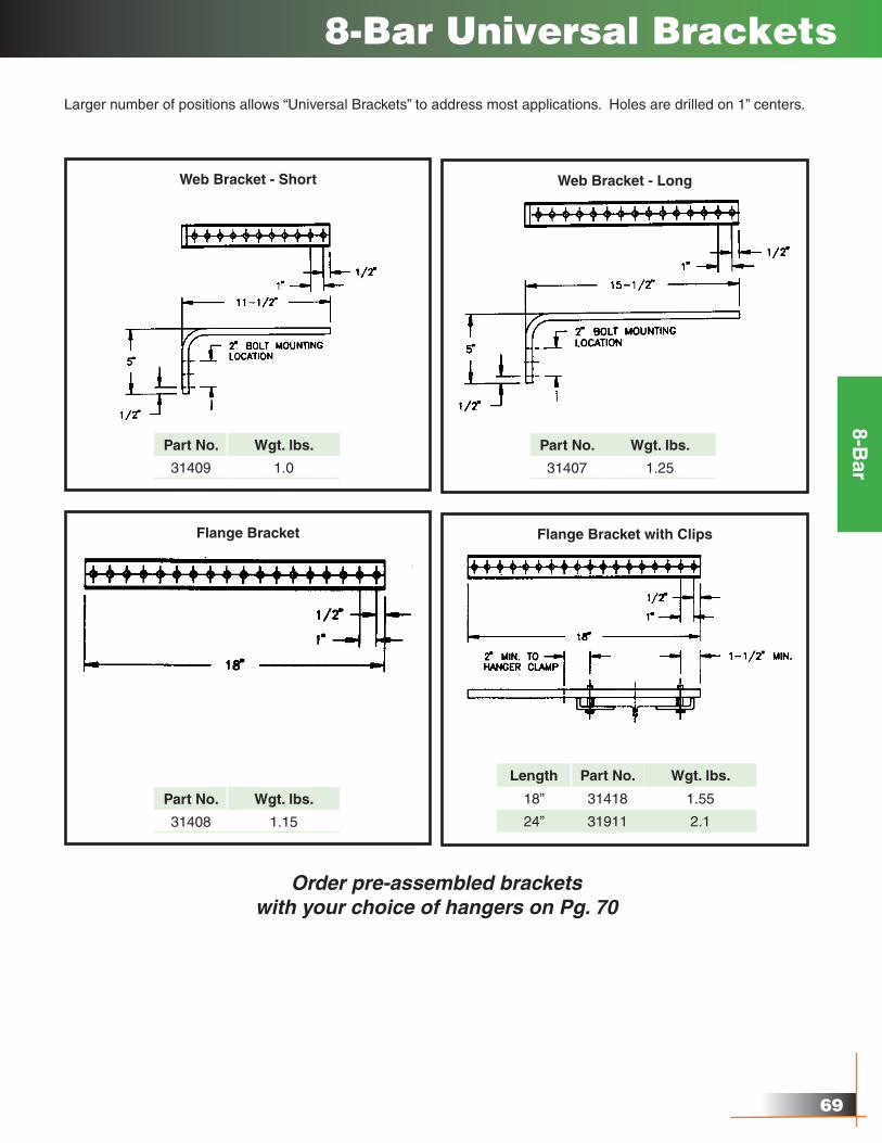
Web Bracket - Short
8-Bar Universal Brackets
Larger number of positions allows “Universal Brackets” to address most applications. Holes are drilled on 1” centers.
Part No. Wgt. lbs.
31409 1.0
Web Bracket - Long
Part No. Wgt. lbs.
31407 1.25
Flange Bracket
Part No. Wgt. lbs.
31408 1.15
Flange Bracket with Clips
Length Part No. Wgt. lbs.
18” 31418 1.55
24” 31911 2.1
Order pre-assembled bracketswith your choice of hangers on Pg. 70
�0
8-Bar
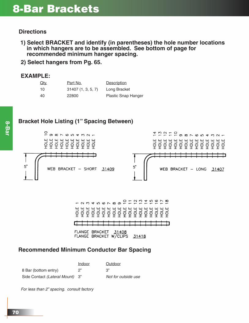
8-Bar Brackets
Directions
1) Select BRACKET and identify (in parentheses) the hole number locations in which hangers are to be assembled. See bottom of page for recommended minimum hanger spacing.2) Select hangers from Pg. 65.
EXAMPLE:Qty. Part No. Description
10 31407 (1, 3, 5, 7) Long Bracket
40 22800 Plastic Snap Hanger
Bracket Hole Listing (1” Spacing Between)
Recommended Minimum Conductor Bar Spacing
Indoor Outdoor
8 Bar (bottom entry) 2” 3”
Side Contact (Lateral Mount) 3” Not for outside use
For less than 2” spacing. consult factory
�1
8-Bar
8-Bar Curves & Slip Rings
Curves
Slip Rings
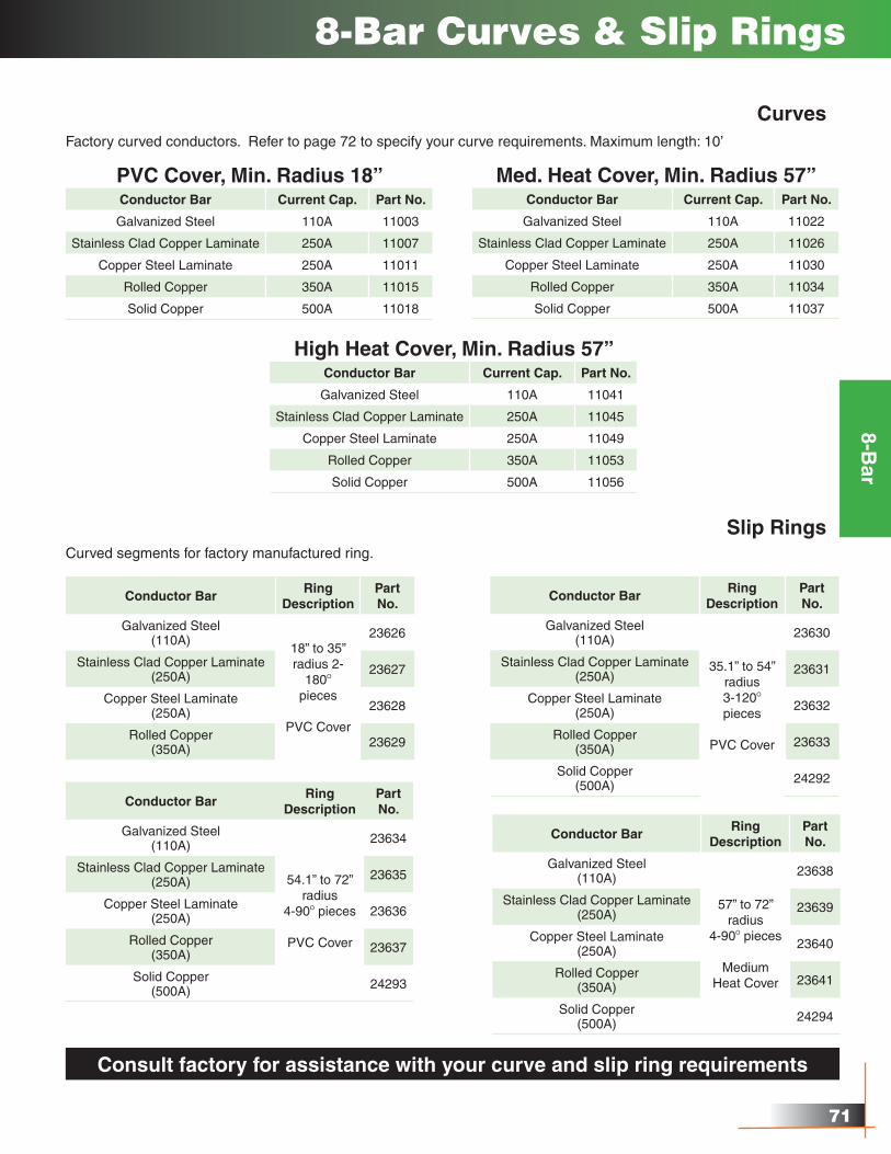
Factory curved conductors. Refer to page 72 to specify your curve requirements. Maximum length: 10’
PVC Cover, Min. Radius 18”Conductor Bar Current Cap. Part No.
Galvanized Steel 110A 11003
Stainless Clad Copper Laminate 250A 11007
Copper Steel Laminate 250A 11011
Rolled Copper 350A 11015
Solid Copper 500A 11018
Med. Heat Cover, Min. Radius 57”Conductor Bar Current Cap. Part No.
Galvanized Steel 110A 11022
Stainless Clad Copper Laminate 250A 11026
Copper Steel Laminate 250A 11030
Rolled Copper 350A 11034
Solid Copper 500A 11037
High Heat Cover, Min. Radius 57”Conductor Bar Current Cap. Part No.
Galvanized Steel 110A 11041
Stainless Clad Copper Laminate 250A 11045
Copper Steel Laminate 250A 11049
Rolled Copper 350A 11053
Solid Copper 500A 11056
Conductor BarRing
DescriptionPart No.
Galvanized Steel(110A)
18” to 35”radius 2-
180O
pieces
PVC Cover
23626
Stainless Clad Copper Laminate (250A) 23627
Copper Steel Laminate(250A) 23628
Rolled Copper(350A) 23629
Curved segments for factory manufactured ring.
Conductor BarRing
DescriptionPart No.
Galvanized Steel (110A)
35.1” to 54”radius3-120O
pieces
PVC Cover
23630
Stainless Clad Copper Laminate (250A) 23631
Copper Steel Laminate(250A) 23632
Rolled Copper(350A) 23633
Solid Copper(500A) 24292
Conductor BarRing
DescriptionPart No.
Galvanized Steel (110A)
54.1” to 72”radius
4-90O pieces
PVC Cover
23634
Stainless Clad Copper Laminate (250A) 23635
Copper Steel Laminate(250A) 23636
Rolled Copper(350A) 23637
Solid Copper(500A) 24293
Conductor BarRing
DescriptionPart No.
Galvanized Steel (110A)
57” to 72”radius
4-90O pieces
Medium Heat Cover
23638
Stainless Clad Copper Laminate (250A) 23639
Copper Steel Laminate(250A) 23640
Rolled Copper(350A) 23641
Solid Copper(500A) 24294
Consult factory for assistance with your curve and slip ring requirements
��
8-Bar
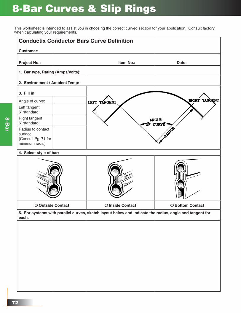
8-Bar Curves & Slip Rings
This worksheet is intended to assist you in choosing the correct curved section for your application. Consult factory when calculating your requirements.
Conductix Conductor Bars Curve Definition
Customer:
Project No.: Item No.: Date:
1. Bar type, Rating (Amps/Volts):
2. Environment / Ambient Temp:
3. Fill in
Angle of curve:
Left tangent 6” standard:
Right tangent 6” standard:
Radius to contact surface:(Consult Pg. 71 for minimum radii.)
4. Select style of bar:
Outside Contact Inside Contact Bottom Contact
5. For systems with parallel curves, sketch layout below and indicate the radius, angle and tangent for each.
��
8-Bar
8-Bar Collector Drawings
��
8-Bar
Hangers
8-Bar Hanger & Power Feed Drawings
Powerfeeds
��
8-Bar
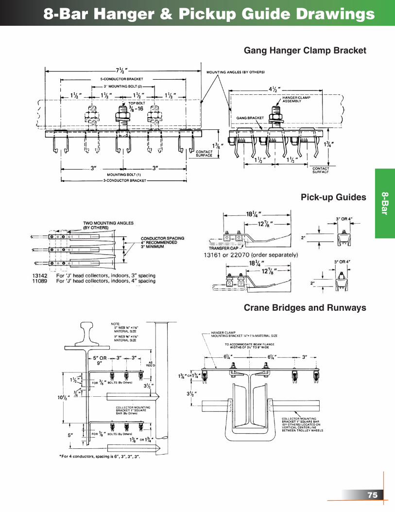
Gang Hanger Clamp Bracket
8-Bar Hanger & Pickup Guide Drawings
Pick-up Guides
Crane Bridges and Runways
��
Appendix I - Selection of Systems
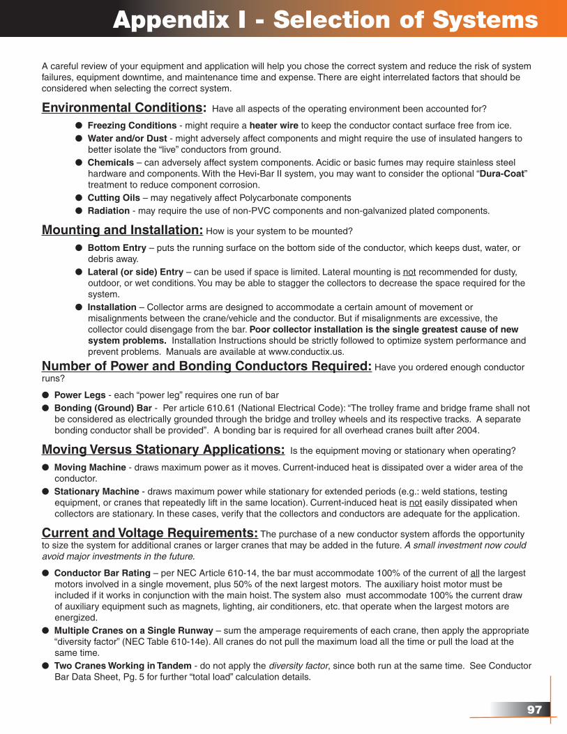
A careful review of your equipment and application will help you chose the correct system and reduce the risk of system failures, equipment downtime, and maintenance time and expense. There are eight interrelated factors that should be considered when selecting the correct system.
Environmental Conditions: Have all aspects of the operating environment been accounted for?
l Freezing Conditions - might require a heater wire to keep the conductor contact surface free from ice. l Water and/or Dust - might adversely affect components and might require the use of insulated hangers to better isolate the “live” conductors from ground. l Chemicals – can adversely affect system components. Acidic or basic fumes may require stainless steel hardware and components. With the Hevi-Bar II system, you may want to consider the optional “Dura-Coat” treatment to reduce component corrosion. l Cutting Oils – may negatively affect Polycarbonate components l Radiation - may require the use of non-PVC components and non-galvanized plated components.
Mounting and Installation: How is your system to be mounted?
l Bottom Entry – puts the running surface on the bottom side of the conductor, which keeps dust, water, or debris away. l Lateral (or side) Entry – can be used if space is limited. Lateral mounting is not recommended for dusty, outdoor, or wet conditions. You may be able to stagger the collectors to decrease the space required for the system. l Installation – Collector arms are designed to accommodate a certain amount of movement or misalignments between the crane/vehicle and the conductor. But if misalignments are excessive, the collector could disengage from the bar. Poor collector installation is the single greatest cause of new system problems. Installation Instructions should be strictly followed to optimize system performance and prevent problems. Manuals are available at www.conductix.us.
Number of Power and Bonding Conductors Required: Have you ordered enough conductor runs?
l Power Legs - each “power leg” requires one run of barl Bonding (Ground) Bar - Per article 610.61 (National Electrical Code): “The trolley frame and bridge frame shall not be considered as electrically grounded through the bridge and trolley wheels and its respective tracks. A separate bonding conductor shall be provided”. A bonding bar is required for all overhead cranes built after 2004.
Moving Versus Stationary Applications: Is the equipment moving or stationary when operating?
l Moving Machine - draws maximum power as it moves. Current-induced heat is dissipated over a wider area of the conductor.l Stationary Machine - draws maximum power while stationary for extended periods (e.g.: weld stations, testing equipment, or cranes that repeatedly lift in the same location). Current-induced heat is not easily dissipated when collectors are stationary. In these cases, verify that the collectors and conductors are adequate for the application.
Current and Voltage Requirements: The purchase of a new conductor system affords the opportunity to size the system for additional cranes or larger cranes that may be added in the future. A small investment now could avoid major investments in the future.
l Conductor Bar Rating – per NEC Article 610-14, the bar must accommodate 100% of the current of all the largest motors involved in a single movement, plus 50% of the next largest motors. The auxiliary hoist motor must be included if it works in conjunction with the main hoist. The system also must accommodate 100% the current draw of auxiliary equipment such as magnets, lighting, air conditioners, etc. that operate when the largest motors are energized.l Multiple Cranes on a Single Runway – sum the amperage requirements of each crane, then apply the appropriate “diversity factor” (NEC Table 610-14e). All cranes do not pull the maximum load all the time or pull the load at the same time.l Two Cranes Working in Tandem - do not apply the diversity factor, since both run at the same time. See Conductor Bar Data Sheet, Pg. 5 for further “total load” calculation details.
�8
l Voltage Rating - 600 volt rated insulating covers are standard. Higher voltages require covers designed for that voltage. Conductor separation may also be affected for medium voltage (e.g. 4160 volts) and higher. The conductor system may need to meet the fault force requirements as determined by a qualified engineer.
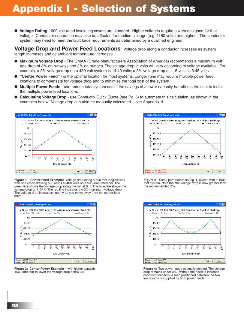
Voltage Drop and Power Feed Locations: Voltage drop along a conductor increases as system length increases and as ambient temperature increases.
l Maximum Voltage Drop - The CMAA (Crane Manufacturers Association of America) recommends a maximum volt age drop of 3% on runways and 2% on bridges. The voltage drop in volts will vary according to voltage available. For example, a 3% voltage drop on a 480 volt system is 14.40 volts; a 3% voltage drop at 115 volts is 3.45 volts.l “Center Power Feed” - is the optimal location for most systems. Longer runs may require multiple power feed locations to compensate for voltage drop and to minimize the total cost of the system.l Multiple Power Feeds - can reduce total system cost if the savings of a lower capacity bar offsets the cost to install the multiple power feed locations.l Calculating Voltage Drop - use Conductix Quick Quote (see Pg. 5) to automate this calculation, as shown in the examples below. Voltage drop can also be manually calculated – see Appendix II.
Appendix I - Selection of Systems
Figure 1 – Center Feed Example: Voltage drop along a 500 foot long runway with one crane drawing 500 amps at 460 volts on a 500 amp rated bar. The green line shows the voltage drop along the run at 0O F. The blue line shows the voltage drop at 110O F. The red line indicates the 3% maximum voltage drop. The voltage drop increases linearly as you move away from the center feed point.
Figure 2 - Same parameters as Fig. 1, except with a 1000 foot system. Note that the voltage drop is now greater than the recommended 3%.
Figure 3: Center Power Example – with higher capacity 1500 amp bar to lower the voltage drop below 3%.
Figure 4: Two power feeds optimally located. The voltage drop remains under 3% , without the need to increase conductor capacity. A load positioned between the two feed points is supplied by both power feeds.
��
Thermal Expansion/Contraction and Other Effects of Heat: The effects of thermal expansion and contraction become more pronounced as the length of the run increases. The combination of ambient heat plus current-induced heat affects the size of conductor bar needed, the power feed arrangement, and the type of insulating cover required.
l “Snaking” – occurs when the conductors heat up, and due to cumulative hanger friction, start to bow to the side. This can be observed by sighting down the runway. Each bar will bow alternately left and right between hangers, which puts strain on the collectors and hangers. Eventually, the collectors can disengage and damage the system.
l “Snaking” - Older Systems - may begin after a year or two in operation. This is because accumulated dirt increases friction between bar and hangers. This possibility should be considered when determining the number of expansions. Precautions taken at the time of installation could avoid costly repairs later.
l Shorter Systems - can be anchored in the center. As the temperature of the conductor rises, the expansion simply pushes the bar outward. The longest system that can be successfully “center-anchored” depends on the friction of the hangers and the rigidity of the conductor.
l Longer Systems - require the installation of one or more “Expansion sections”, which are lengths of conductors designed to slide in and out to absorb bar expansion/contraction between anchor points. The slider is bridged by a jumper cable to maintain electrical continuity and acts as the running surface for the collector. Expansion sections effectively break the run into smaller lengths defined by the anchor points. The length of run an expansion section can accommodate is based on expansion/contraction parameters, including temperature range, conductor material, and the length of the slider. The high end of the temperature range is the sum of current-induced heat of the bar (at maximum load) plus the highest ambient temperature. The low end is the lowest ambient temperature, which may occur during a January system shutdown. Conductor sections needs to be anchored properly between each expansion and between the last expansion and the end of the run.
l Ambient Heat – All heat sources must be considered and evaluated for their effect on the conductor and cover. Typical heat sources are furnaces, billets, slag, etc. Ambient heat is easy to measure and the effects are consistent with measured values.
l Radiant Heat - can be difficult to measure and its effects hard to anticipate. It will directly affect cover, and the cover might withstand it. However, the effect on metal components might be even more pronounced. For example, metal hangers may heat to such a degree that they will melt the cover. Heat shields provide a good way of minimizing the effects of radiant heat. If heat shields are not practical, higher temperature rated covers might be required.
l Total Operating Temperature – the sum of the ambient temperature, radiant heat, and current-induced temperature rise. This is the total heat the conductor and its cover material must withstand. For example, if your machine is working in an ambient temperature of 120O F (49O C), and the current-induced temperature rise of the conductor adds another 50O F, the total 170O F (76.7O C) exceeds the PVC cover rating of 70O C (156O F). The cover will deform or melt, and interfere with collector tracking and/or interrupt power. In this scenario, the cover must be made from a heat-resistant material. Conductix offers “Medium Heat” or “High Heat” covers for most systems – see Pg. 3.
Conductor Bar Current Rating and Duty Cyclel Conductor Electrical Capacity – a wide variety of capacities are offered, since conductors often power multiple vehicles. Ratings are based on the electrical load the conductor can handle before the operating temperature of the bar exceeds the temperature rating of its cover. The rating assumes a certain ambient temperature (e.g.: 49O C or 120O F) and a specific duty cycle.
l Duty Cycle - one manufacturer may rate their conductors for continuous duty; others for intermittent duty based on a given duty cycle. It is important to know which was used to establish the ratings.
l Continuous Duty - a conductor is put under a continuous load at some “normal” ambient, usually 30O C. Once the bar temperature has stabilized at the target load rating, the bar temperature cannot exceed the temperature rating of the cover. Most PVC covers can handle approximately 70O C, which is a 40O C rise over 30O C ambient.
Appendix I - Selection of Systems
100
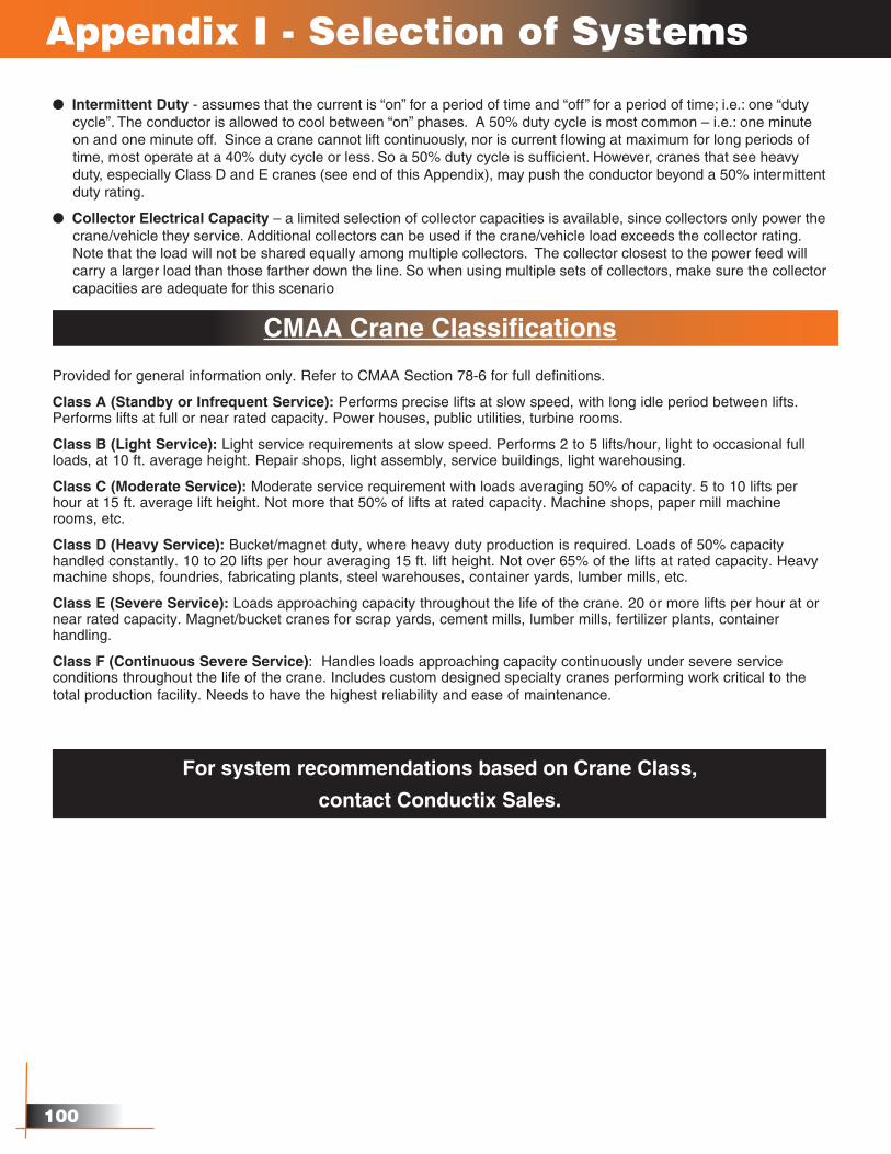
l Intermittent Duty - assumes that the current is “on” for a period of time and “off” for a period of time; i.e.: one “duty cycle”. The conductor is allowed to cool between “on” phases. A 50% duty cycle is most common – i.e.: one minute on and one minute off. Since a crane cannot lift continuously, nor is current flowing at maximum for long periods of time, most operate at a 40% duty cycle or less. So a 50% duty cycle is sufficient. However, cranes that see heavy duty, especially Class D and E cranes (see end of this Appendix), may push the conductor beyond a 50% intermittent duty rating.
l Collector Electrical Capacity – a limited selection of collector capacities is available, since collectors only power the crane/vehicle they service. Additional collectors can be used if the crane/vehicle load exceeds the collector rating. Note that the load will not be shared equally among multiple collectors. The collector closest to the power feed will carry a larger load than those farther down the line. So when using multiple sets of collectors, make sure the collector capacities are adequate for this scenario
CMAA Crane Classifications
Provided for general information only. Refer to CMAA Section 78-6 for full definitions.
Class A (Standby or Infrequent Service): Performs precise lifts at slow speed, with long idle period between lifts. Performs lifts at full or near rated capacity. Power houses, public utilities, turbine rooms.
Class B (Light Service): Light service requirements at slow speed. Performs 2 to 5 lifts/hour, light to occasional full loads, at 10 ft. average height. Repair shops, light assembly, service buildings, light warehousing.
Class C (Moderate Service): Moderate service requirement with loads averaging 50% of capacity. 5 to 10 lifts per hour at 15 ft. average lift height. Not more that 50% of lifts at rated capacity. Machine shops, paper mill machine rooms, etc.
Class D (Heavy Service): Bucket/magnet duty, where heavy duty production is required. Loads of 50% capacity handled constantly. 10 to 20 lifts per hour averaging 15 ft. lift height. Not over 65% of the lifts at rated capacity. Heavy machine shops, foundries, fabricating plants, steel warehouses, container yards, lumber mills, etc.
Class E (Severe Service): Loads approaching capacity throughout the life of the crane. 20 or more lifts per hour at or near rated capacity. Magnet/bucket cranes for scrap yards, cement mills, lumber mills, fertilizer plants, container handling.
Class F (Continuous Severe Service): Handles loads approaching capacity continuously under severe service conditions throughout the life of the crane. Includes custom designed specialty cranes performing work critical to the total production facility. Needs to have the highest reliability and ease of maintenance.
Appendix I - Selection of Systems
For system recommendations based on Crane Class,
contact Conductix Sales.
101
Appendix II - Voltage Drop Calculations
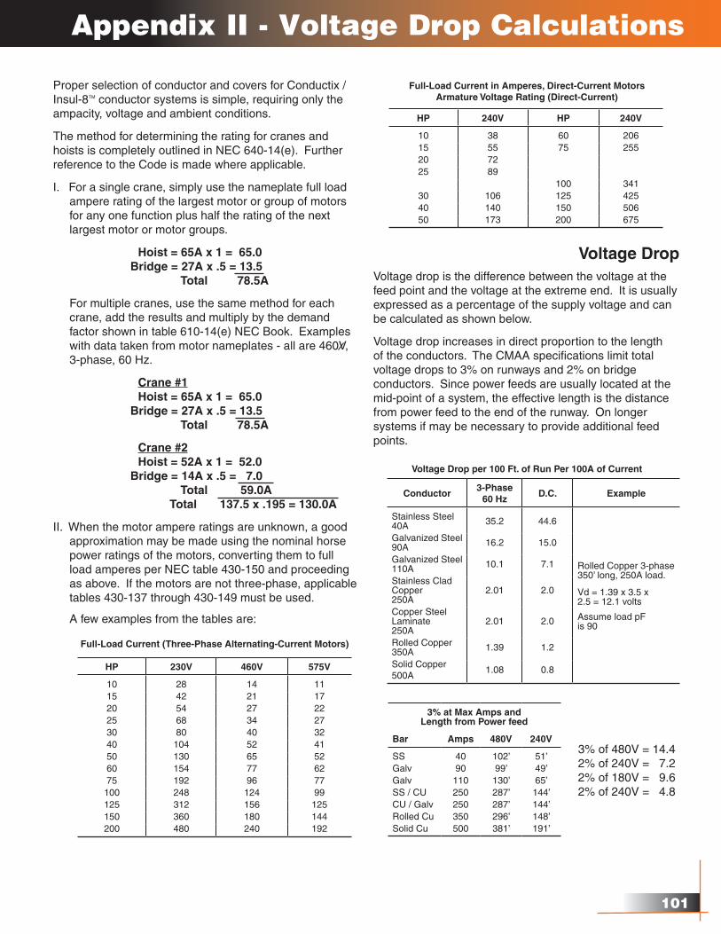
Proper selection of conductor and covers for Conductix / Insul-8TM conductor systems is simple, requiring only the ampacity, voltage and ambient conditions.
The method for determining the rating for cranes and hoists is completely outlined in NEC 640-14(e). Further reference to the Code is made where applicable.
I. For a single crane, simply use the nameplate full load ampere rating of the largest motor or group of motors for any one function plus half the rating of the next largest motor or motor groups.
Hoist = 65A x 1 = 65.0 Bridge = 27A x .5 = 13.5 Total 78.5A
For multiple cranes, use the same method for each crane, add the results and multiply by the demand factor shown in table 610-14(e) NEC Book. Examples with data taken from motor nameplates - all are 460V, 3-phase, 60 Hz.
Crane #1 Hoist = 65A x 1 = 65.0 Bridge = 27A x .5 = 13.5 Total 78.5A
Crane #2 Hoist = 52A x 1 = 52.0 Bridge = 14A x .5 = 7.0 Total 59.0A Total 137.5 x .195 = 130.0A
II. When the motor ampere ratings are unknown, a good approximation may be made using the nominal horse power ratings of the motors, converting them to full load amperes per NEC table 430-150 and proceeding as above. If the motors are not three-phase, applicable tables 430-137 through 430-149 must be used.
A few examples from the tables are:
Voltage DropVoltage drop is the difference between the voltage at the feed point and the voltage at the extreme end. It is usually expressed as a percentage of the supply voltage and can be calculated as shown below.
Voltage drop increases in direct proportion to the length of the conductors. The CMAA specifications limit total voltage drops to 3% on runways and 2% on bridge conductors. Since power feeds are usually located at the mid-point of a system, the effective length is the distance from power feed to the end of the runway. On longer systems if may be necessary to provide additional feed points.
HP 230V 460V 575V
10 28 14 1115 42 21 1720 54 27 2225 68 34 2730 80 40 3240 104 52 4150 130 65 5260 154 77 6275 192 96 77100 248 124 99125 312 156 125150 360 180 144200 480 240 192
Full-Load Current (Three-Phase Alternating-Current Motors)
Full-Load Current in Amperes, Direct-Current MotorsArmature Voltage Rating (Direct-Current)
HP 240V HP 240V
10 38 60 20615 55 75 25520 7225 89
100 34130 106 125 42540 140 150 50650 173 200 675
Voltage Drop per 100 Ft. of Run Per 100A of Current
Conductor3-Phase
60 HzD.C. Example
Stainless Steel 40A 35.2 44.6
Rolled Copper 3-phase 350’ long, 250A load.
Vd = 1.39 x 3.5 x2.5 = 12.1 volts
Assume load pFis 90
Galvanized Steel90A 16.2 15.0
Galvanized Steel110A 10.1 7.1
Stainless CladCopper250A
2.01 2.0
Copper Steel Laminate250A
2.01 2.0
Rolled Copper350A 1.39 1.2
Solid Copper500A
1.08 0.8
3% at Max Amps andLength from Power feed
Bar Amps 480V 240V
SS 40 102’ 51’Galv 90 99’ 49’Galv 110 130’ 65’SS / CU 250 287’ 144’CU / Galv 250 287’ 144’Rolled Cu 350 296’ 148’Solid Cu 500 381’ 191’
3% of 480V = 14.42% of 240V = 7.22% of 180V = 9.62% of 240V = 4.8
10�
Appendix III Electrical Formulas & Conversions
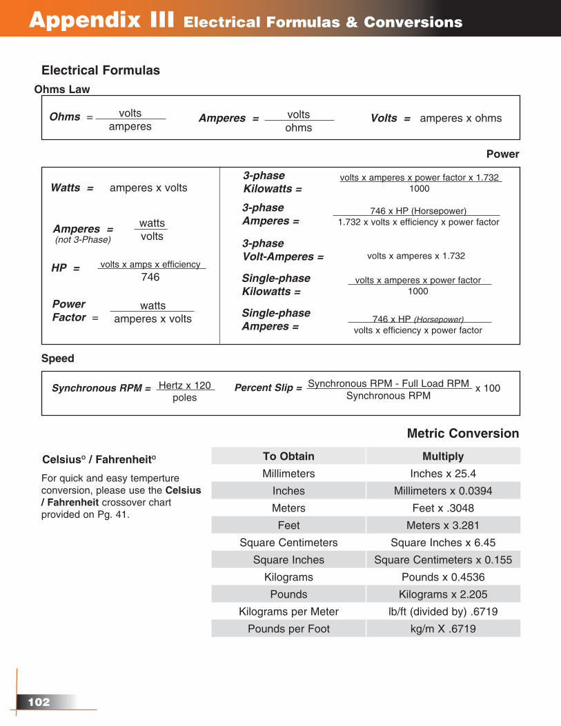
Electrical FormulasOhms Law
Power
Speed
voltsamperes
Ohms = voltsohms
Amperes = Volts = amperes x ohms
wattsvolts
Amperes =(not 3-Phase)
Watts = amperes x volts
volts x amperes x 1.732
volts x amperes x power factor x 1.7321000
3-phaseKilowatts =
3-phaseVolt-Amperes =
volts x amperes x power factor1000
Single-phaseKilowatts =
746 x HP (Horsepower)1.732 x volts x efficiency x power factor
3-phaseAmperes =
746 x HP (Horsepower)volts x efficiency x power factor
Single-phaseAmperes =
wattsamperes x volts
PowerFactor =
volts x amps x efficiency746
HP =
Hertz x 120poles
Synchronous RPM = Synchronous RPM - Full Load RPMSynchronous RPM
Percent Slip = x 100
Metric Conversion
To Obtain Multiply
Millimeters Inches x 25.4
Inches Millimeters x 0.0394
Meters Feet x .3048
Feet Meters x 3.281
Square Centimeters Square Inches x 6.45
Square Inches Square Centimeters x 0.155
Kilograms Pounds x 0.4536
Pounds Kilograms x 2.205
Kilograms per Meter lb/ft (divided by) .6719
Pounds per Foot kg/m X .6719
For quick and easy temperture conversion, please use the Celsius / Fahrenheit crossover chart provided on Pg. 41.
CelsiusO / FahrenheitO
10�
Appendix IV - Power Interrupting Sections
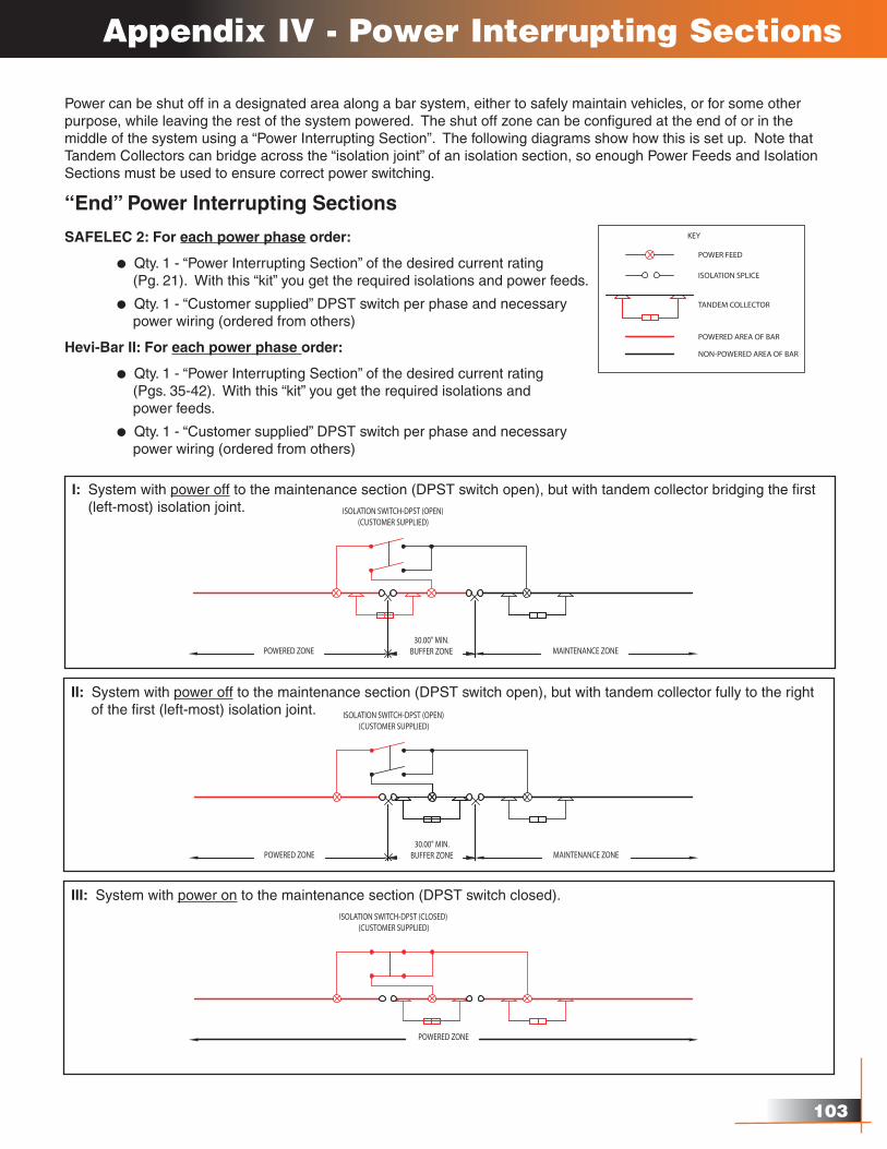
Power can be shut off in a designated area along a bar system, either to safely maintain vehicles, or for some other purpose, while leaving the rest of the system powered. The shut off zone can be configured at the end of or in the middle of the system using a “Power Interrupting Section”. The following diagrams show how this is set up. Note that Tandem Collectors can bridge across the “isolation joint” of an isolation section, so enough Power Feeds and Isolation Sections must be used to ensure correct power switching.
“End” Power Interrupting Sections
SAFELEC 2: For each power phase order:
l Qty. 1 - “Power Interrupting Section” of the desired current rating (Pg. 21). With this “kit” you get the required isolations and power feeds.
l Qty. 1 - “Customer supplied” DPST switch per phase and necessary power wiring (ordered from others)
Hevi-Bar II: For each power phase order:
l Qty. 1 - “Power Interrupting Section” of the desired current rating (Pgs. 35-42). With this “kit” you get the required isolations and power feeds.
l Qty. 1 - “Customer supplied” DPST switch per phase and necessary power wiring (ordered from others)
I: System with power off to the maintenance section (DPST switch open), but with tandem collector bridging the first (left-most) isolation joint.
II: System with power off to the maintenance section (DPST switch open), but with tandem collector fully to the right of the first (left-most) isolation joint.
III: System with power on to the maintenance section (DPST switch closed).
10�
Appendix IV - Power Interrupting Sections
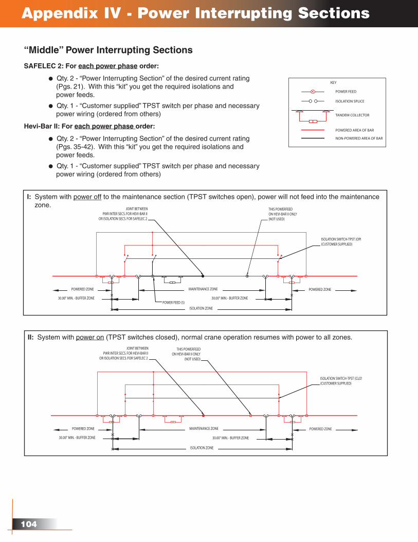
“Middle” Power Interrupting Sections
SAFELEC 2: For each power phase order:
l Qty. 2 - “Power Interrupting Section” of the desired current rating (Pgs. 21). With this “kit” you get the required isolations and power feeds.
l Qty. 1 - “Customer supplied” TPST switch per phase and necessary power wiring (ordered from others)
Hevi-Bar II: For each power phase order:
l Qty. 2 - “Power Interrupting Section” of the desired current rating (Pgs. 35-42). With this “kit” you get the required isolations and power feeds.
l Qty. 1 - “Customer supplied” TPST switch per phase and necessary power wiring (ordered from others)
I: System with power off to the maintenance section (TPST switches open), power will not feed into the maintenance zone.
II: System with power on (TPST switches closed), normal crane operation resumes with power to all zones.
10�
About CONDUCTIX
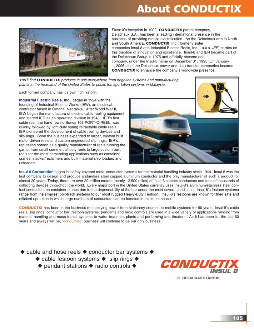
Industrial Electric Reels, Inc., began in 1924 with the founding of Industrial Electric Works (IEW), an electrical contractor based in Omaha, Nebraska. After World War II, IEW began the manufacture of electric cable reeling equipment and started IER as an operating division in 1948. IER’s first cable reel, the hand rewind Series 102 PORT-O-REEL, was quickly followed by light-duty spring retractable cable reels. IER pioneered the development of cable reeling devices and slip rings. Soon the business expanded to larger, custom built motor driven reels and custom engineered slip rings. IER’s reputation spread as a quality manufacturer of reels running the gamut from small commercial duty reels to large custom built reels for the most demanding applications such as container cranes, stacker/reclaimers and bulk material ship loaders and unloaders.
Insul-8 Corporation began in safety-covered metal conductor systems for the material handling industry since 1944. Insul-8 was the first company to design and produce a stainless steel capped aluminum conductor and the only manufacturer of such a product for almost 20 years. Today, there are over 20 million meters (nearly 12,500 miles) of Insul-8 contact conductors and tens of thousands of collecting devices throughout the world. Every major port in the United States currently uses Insul-8’s aluminum/stainless steel con-tact conductors on container cranes due to the dependability of the bar under the most severe conditions. Insul-8’s festoon systems range from the smallest box-track systems to our most rugged Heavy-Duty Festoon. Insul-8’s festoons are known for their safe and efficient operation in which large numbers of conductors can be handled in minimum space.
CONDUCTIX has been in the business of supplying power from stationary sources to mobile systems for 60 years. Insul-8’s cable reels, slip rings, conductor bar, festoon systems, pendants and radio controls are used in a wide variety of applications ranging from material handling and mass transit systems to water treatment plants and performing arts theaters. As it has been for the last 60 years and always will be, “conducting” business will continue to be our only business.
Since it’s inception in 1902, CONDUCTIX parent company, Delachaux S.A., has been a leading international presence in the business of providing mobile electrification. As the Delachaux arm in North and South America, CONDUCTIX Inc. (formerly sister companies Insul-8 and Industrial Electric Reels, Inc. - a.k.a. IER) carries on this tradition of innovation and excellence. Insul-8 and IER became part of the Delachaux Group in 1975 and officially became one company, under the Insul-8 name on December 31, 1996. On January 1, 2006 all of the Delachaux power and data transfer companies became CONDUCTIX to enhance the company’s worldwide presence.
You’ll find CONDUCTIX products in use everywhere from irrigation systems and manufacturing plants in the heartland of the United States to public transportation systems in Malaysia.
u cable and hose reels u conductor bar systems u u cable festoon systems u slip rings u u pendant stations u radio controls u
Each former company has it’s own rich history:
10�
CONDUCTIX INC.
The technical data and images which appear in this manual are for informational purposes only. NO WARRANTIES,EXPRESSED OR IMPLIED, INCLUDING WARRANTIES OF MERCHANTABILITY OR FITNESS FOR A PARTICULAR PURPOSE, ARE CREATED BY THE DESCRIPTIONS AND DEPICTIONS OF THE PRODUCTS SHOWN IN THIS MANUAL. CONDUCTIX makes no warranty (and assumes no liability) as to the function of equipment or the operation of systems built according to customer design; or of the ability of any of its products to interface, operate or function with any portions of customer systems not provided by CONDUCTIX.
Seller agrees to repair or exchange the goods sold hereunder necessitated by reason of defective workmanship, andmaterial discovered and reported to Seller within one year after shipment of such goods to Buyer.
Except where the nature of the defect is such that it is appropriate in Seller’s judgement to effect repairs on site. Seller’s obligation hereunder to remedy defects shall be limited to repairing or replacing (at Seller’s option), FOB point of original shipment by Seller, any part returned to Seller at the risk and cost of Buyer. Defective parts replaced by Seller shall become the property of Seller.
Seller shall only be obligated to make such repair or replacement of the goods which have been used by Buyer in service recommended by Seller and altered only as authorized by Seller. Seller is not responsible for defects which arise from improper installation, neglect, or improper use or from normal wear and tear.
Additionally, Seller’s obligation shall be limited by the manufacturer’s warranty, (and shall not be further warranted by Seller) for all parts procured from others according to published data, specifications or performance information not designed by or for Seller.
Seller further agrees to replace, or at Seller’s option to provide a refund of the sales price of any goods that did not conform to applicable specifications or which differ from that agreed to be supplied which non-conformity is discovered and forthwith reported to Seller within thirty (30) days after shipment to Buyer. Seller’s obligation to replace or refund the purchase price for non-conforming goods shall arise once Buyer returns such good FOB point of original shipment by Seller at the risk and cost of Buyer. Goods replaced by Seller shall be come property of Seller.
There is no guarantee or warranty as to anything made or sold by Seller, or any service performed, except as to title and freedom from encumbrances, and except as herein expressly stated and particularly without limiting the foregoing. There is no guarantee or warranty, express or implied, of merchantability or of fitness for any particular purpose or against claim of infringement or the like.
Seller makes no warranty (and assumes no liability) as to function of equipment or operation of systems built to Buyer’s design or of the ability of any goods to interface, operate or function with any portions of Buyer’s system not provided by Seller.
Seller’s liability on any claim; whether in contract (including negligence) or otherwise, for any loss or damage arising out of, connected with, or resulting from the manufacture, sale, delivery, resale, repair, replacement or use of any products or, services shall in no case exceed the price paid for the product or services or any part thereof which give rise to the claim. In no event shall Seller be liable for consequential, special, incidental or other damages, nor shall Seller be liable in respect to personal injury or damage to property on the subject matter hereof unless attributable to gross misconduct of Seller, which shall mean an act of omission by Seller demonstrating reckless disregard of the foreseeable consequences thereof.
Seller is not responsible for incorrect choice of models or where products are used in excess of their rated and recommended capacities and design functions or under abnormal conditions. Seller assumes no liability for loss of time, damage or injuries to property or persons resulting from the use of Seller’s products. Buyer shall hold Seller harmless from all liability, claims, suits and expenses in connection with loss or damage resulting from operation of products or utilization of services, respectively, of Seller and shall defend any suit or action which might arise there from Buyer’s name - provided that Seller shall have the right to elect to defend any such suit or action for the account of Buyer. The foregoing shall be the exclusive remedies of the buyer and all persons and entitles claiming through the Buyer.
Terms & Conditions
10�www.conductix.us
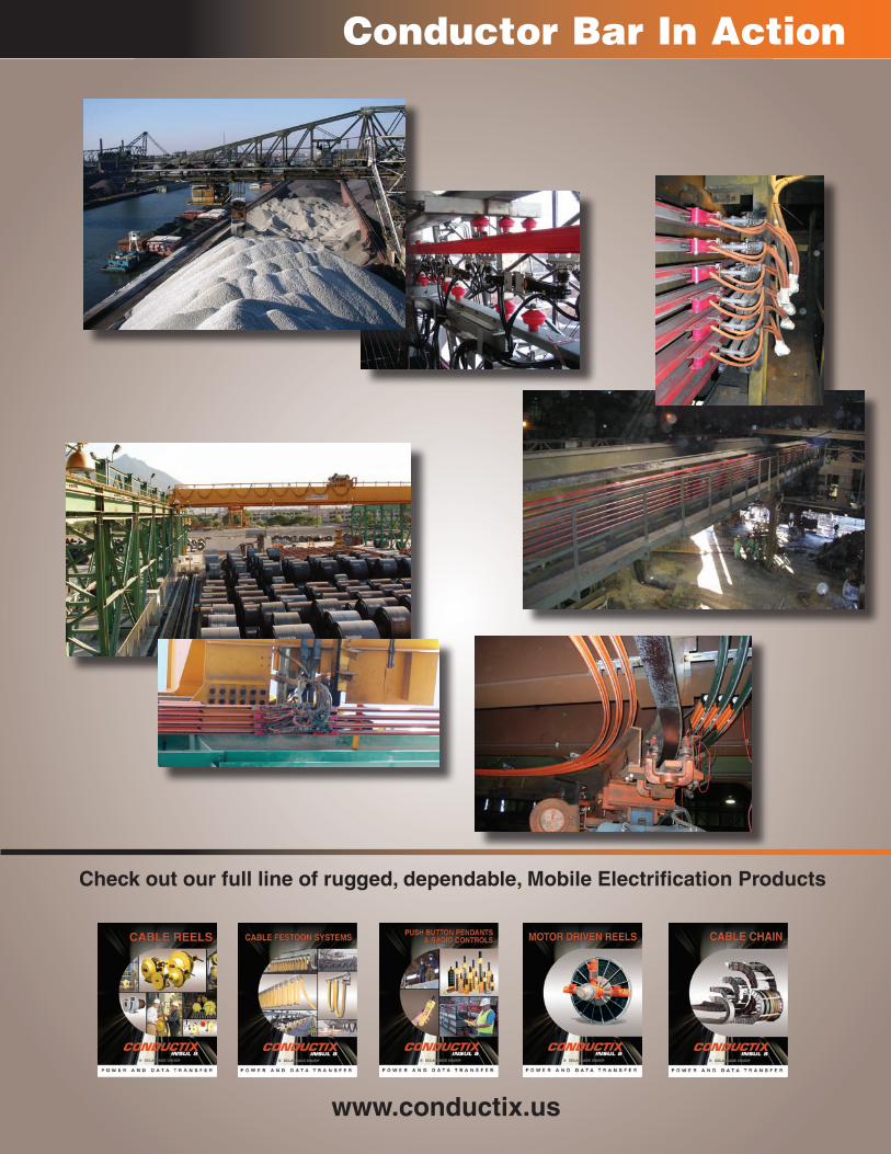
Conductor Bar In Action
Check out our full line of rugged, dependable, Mobile Electrification Products
CAT8105.0.3
Pic
ture
Cre
dit
- C
over
: c
Dig
ital V
isio
n
DELACHAUX S.A119 Avenue Louis Roche - BP15292231 Gennevilliers Cedex FRANCETel: +33 (0) 1 46 88 15 00Fax: +33 (0) 1 46 88 15 [email protected]
CONDUCTIX OPERATIONS119 Avenue Louis Roche - BP15292231 Gennevilliers Cedex FRANCETel: +33 (0) 1 46 88 15 13Fax: +33 (0) 1 46 88 15 [email protected]
CONDUCTIX Worldwide
HEADQUARTERS
ITALYCONDUCTIX Srl (Comes)MilanTel: +39 (0) 39 607 431Fax: +39 (0) 39 607 43292
TurinTel: +39 (0) 11 45 09 007Fax: +39 (0) 11 42 41 [email protected]
MEXICOCONDUCTIX S.de R.L. de C.V. (Insul-8)MonterreyTel: +(52) 811 090 9013Fax: +(52) 811 090 [email protected]
SOUTHEAST ASIACONDUCTIX SingaporeSingaporeTel: +(65) 6329 6405Fax: +(65) 6329 [email protected]
UNITED KINGDOMCONDUCTIX Ltd (Insul-8)SalfordTel: +(44) 161 848 01 61Fax: +(44) 161 873 70 [email protected]
UNITED STATESCONDUCTIX, Inc. (Insul-8)Omaha, NETel: +(1) 800 521 4888 +(1) 402 339 9300Fax: +(1) 800 780 8329 +(1) 402 339 [email protected]
Harlan, IATel: + (1) 402 339 9300Fax: + (1) 402 339 [email protected]
AUSTRALIA
CONDUCTIX Pty. Ltd. (Insul-8)DandenongTel: +(61) 3 97 06 88 44Fax: +(61) 3 97 94 92 [email protected]
BENELUX
CONDUCTIX BeneluxBrusselsTel: +(32) (0) 2 469 25 60Fax: +(32) (0) 2 469 29 [email protected]
CANADA
CONDUCTIX Corp. (Insul-8)St JeromeTel: (450) 565-9900Fax: (450) [email protected]
CHINACONDUCTIX Ltd (Han-Fa)WuhanTel: +(86) 27 83 49 99 88Fax: +(86) 27 83 49 99 [email protected]
FRANCECONDUCTIX (Delachaux)BelleyTel: +(33) (0) 4 79 42 50 00Fax: +(33) (0) 4 79 42 50 [email protected]
GennevilliersTel: +(33) (0) 1 46 88 15 23Fax: +(33) (0) 1 46 88 15 [email protected]
GERMANY / AUSTRIA
CONDUCTIX GmbHOffenbach / MainTel: +(49) 69 98 40 23 0Fax: +(49) 69 98 40 23 [email protected]
Countries where we are also represented:Algeria, Argentina, Austria, Bahrain, Bolivia, Brazil, Bulgaria, Cameroon, Chile, China, Colombia, Congo, Ivory Coast, Croatia, Czech Republic, Denmark, U.A.E., Ecuador, Egypt, Finland, Gabon, Greece, Guatemala, Guinea, Honduras, Hungary, Indonesia, India, Iraq, Iran, Ireland, Israel, Japan, Jordan, Korea, Kuwait, Lebanon, Madagascar, Malaysia, Mali, Mauritania, Mexico, Morocco, Netherlands, New Zealand, Niger, Nigeria, Norway, Pakistan, Panama, Paraguay, Peru, Philippines, Poland, Portugal, Romania, Russia, Saudi Arabia, Senegal, Slovakia, South Africa, Spain, Sweden, Switzerland, Syria, Thailand, Taiwan, Tunisia, Turkey, Uruguay, Venezuela, Vietnam...