Embed Size (px)
Citation preview
18
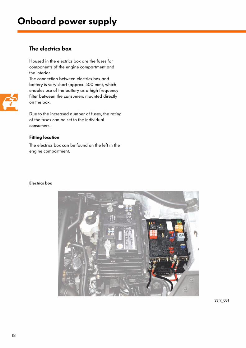
Housed in the electrics box are the fuses for components of the engine compartment and the interior. The connection between electrics box and battery is very short (approx. 500 mm), which enables use of the battery as a high frequency filter between the consumers mounted directly on the box.
Due to the increased number of fuses, the rating of the fuses can be set to the individual consumers.
Fitting location
The electrics box can be found on the left in the engine compartment.
Onboard power supply
S319_031
Electrics box
The electrics box
19
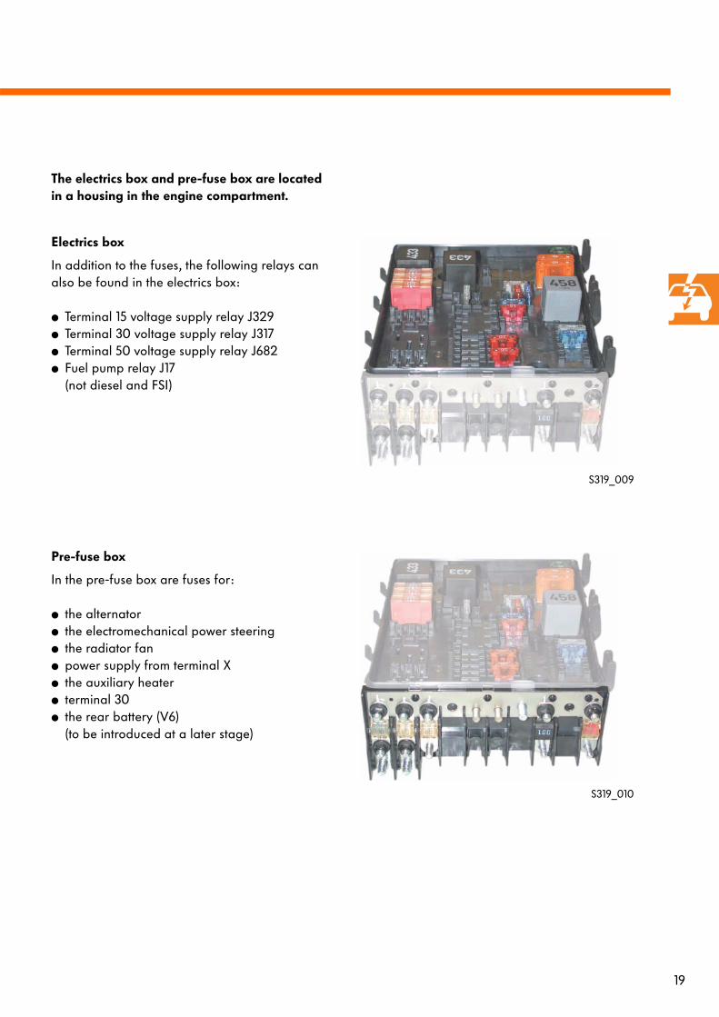
The electrics box and pre-fuse box are located in a housing in the engine compartment.
Electrics box
In addition to the fuses, the following relays can also be found in the electrics box:
● Terminal 15 voltage supply relay J329● Terminal 30 voltage supply relay J317● Terminal 50 voltage supply relay J682● Fuel pump relay J17
(not diesel and FSI)
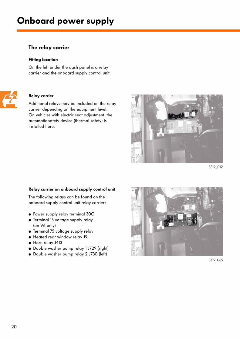
Pre-fuse box
In the pre-fuse box are fuses for:
● the alternator● the electromechanical power steering● the radiator fan● power supply from terminal X● the auxiliary heater● terminal 30● the rear battery (V6)
(to be introduced at a later stage)
S319_009
S319_010
20
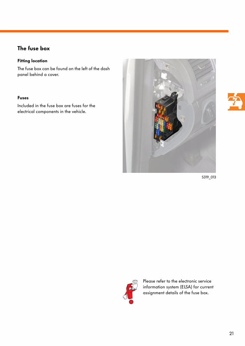
Fitting location
On the left under the dash panel is a relay carrier and the onboard supply control unit.
Relay carrier
Additional relays may be included on the relay carrier depending on the equipment level.On vehicles with electric seat adjustment, the automatic safety device (thermal safety) is installed here.
Relay carrier on onboard supply control unit
The following relays can be found on the onboard supply control unit relay carrier:
● Power supply relay terminal 30G● Terminal 15 voltage supply relay
(on V6 only)● Terminal 75 voltage supply relay● Heated rear window relay J9● Horn relay J413● Double washer pump relay 1 J729 (right)● Double washer pump relay 2 J730 (left)
Onboard power supply
The relay carrier
S319_012
S319_065
21
Fitting location
The fuse box can be found on the left of the dash panel behind a cover.
Fuses
Included in the fuse box are fuses for the electrical components in the vehicle.
S319_013
The fuse box
Please refer to the electronic service information system (ELSA) for current assignment details of the fuse box.
22
Due to the vast range of functions in the vehicle, large amounts of data must be transferred. To guarantee optimal exchange of data, several data bus systems are required.
The function previously integrated in the dash panel insert or onboard supply control unit is now assumed by the separate data bus diagnostic interface (Gateway). It forms the interface for data bus systems that are independent of each other and allows information to be exchanged without conflict or interference.
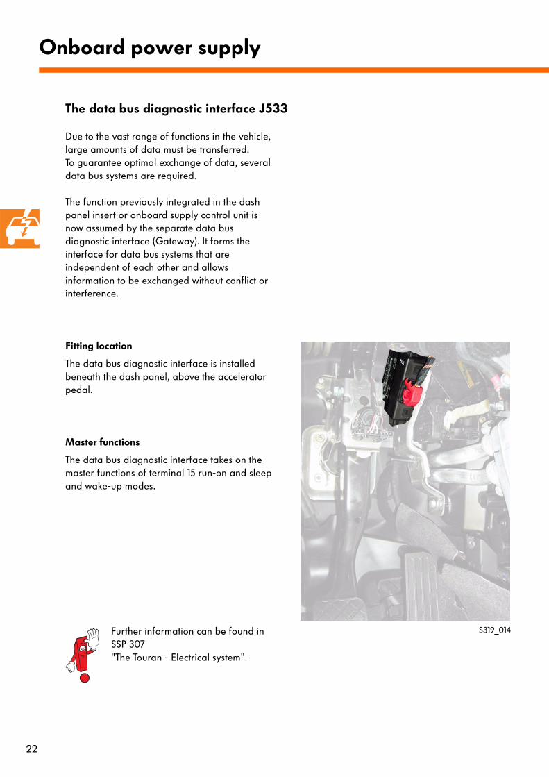
Fitting location
The data bus diagnostic interface is installed beneath the dash panel, above the accelerator pedal.
Master functions
The data bus diagnostic interface takes on the master functions of terminal 15 run-on and sleep and wake-up modes.
Onboard power supply
The data bus diagnostic interface J533
S319_014Further information can be found in SSP 307 "The Touran - Electrical system".
23
Transport mode
For transportation of the vehicles to the dealerships, power consumption should be kept to a minimum to protect the battery from possible discharge.To do this, the following systems are isolated when transport mode is activated:
● Radio● Radio remote control● Interior monitoring● Auxiliary heater telestart receiver● Inclination sensor● Save LED in door● 30 second interior light switch-off delay
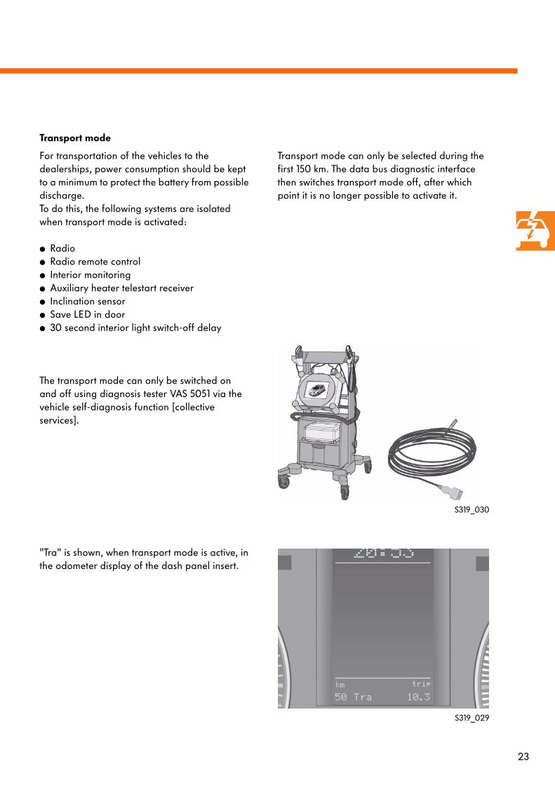
The transport mode can only be switched on and off using diagnosis tester VAS 5051 via the vehicle self-diagnosis function [collective services].
"Tra" is shown, when transport mode is active, in the odometer display of the dash panel insert.
Transport mode can only be selected during the first 150 km. The data bus diagnostic interface then switches transport mode off, after which point it is no longer possible to activate it.
S319_030
S319_029
24
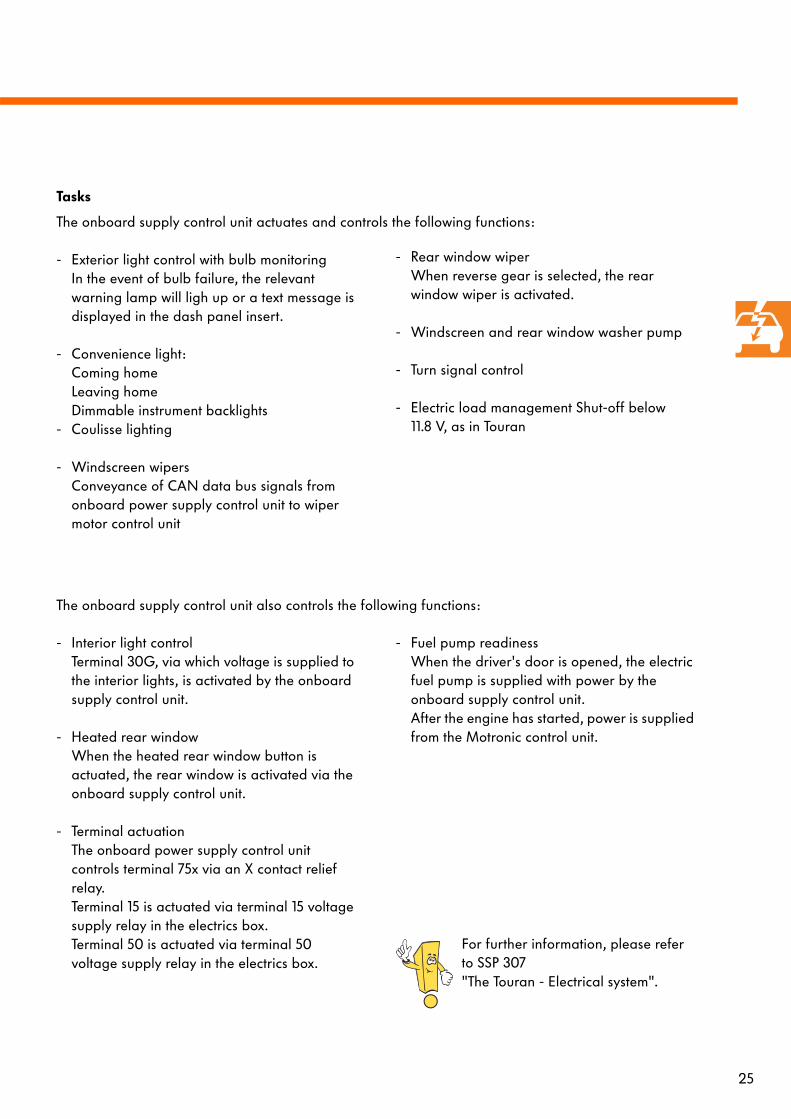
Onboard supply control unit
Relay carrier on onboard supply control unit S307_017
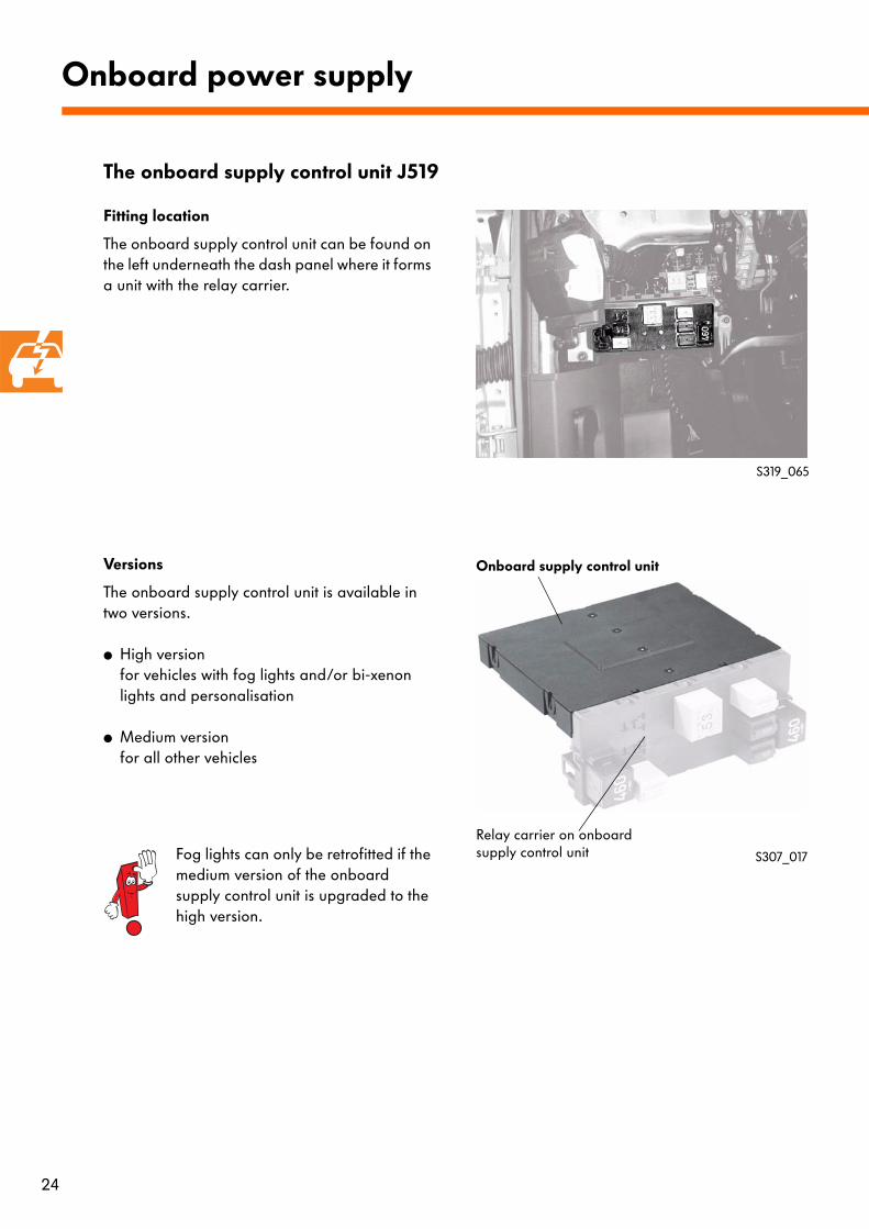
Fitting location
The onboard supply control unit can be found on the left underneath the dash panel where it forms a unit with the relay carrier.
Versions
The onboard supply control unit is available in two versions.
● High versionfor vehicles with fog lights and/or bi-xenon lights and personalisation
● Medium versionfor all other vehicles
Onboard power supply
S319_065
Fog lights can only be retrofitted if the medium version of the onboard supply control unit is upgraded to the high version.
The onboard supply control unit J519
25
- Exterior light control with bulb monitoringIn the event of bulb failure, the relevant warning lamp will ligh up or a text message is displayed in the dash panel insert.
- Convenience light:Coming homeLeaving homeDimmable instrument backlights
- Coulisse lighting
- Windscreen wipersConveyance of CAN data bus signals from onboard power supply control unit to wiper motor control unit
- Interior light controlTerminal 30G, via which voltage is supplied to the interior lights, is activated by the onboard supply control unit.
- Heated rear windowWhen the heated rear window button is actuated, the rear window is activated via the onboard supply control unit.
- Terminal actuationThe onboard power supply control unit controls terminal 75x via an X contact reliefrelay.Terminal 15 is actuated via terminal 15 voltage supply relay in the electrics box.Terminal 50 is actuated via terminal 50 voltage supply relay in the electrics box.
- Fuel pump readinessWhen the driver's door is opened, the electric fuel pump is supplied with power by the onboard supply control unit.After the engine has started, power is supplied from the Motronic control unit.
- Rear window wiperWhen reverse gear is selected, the rear window wiper is activated.
- Windscreen and rear window washer pump
- Turn signal control
- Electric load management Shut-off below 11.8 V, as in Touran
Tasks
The onboard supply control unit actuates and controls the following functions:
The onboard supply control unit also controls the following functions:
For further information, please refer to SSP 307 "The Touran - Electrical system".
26
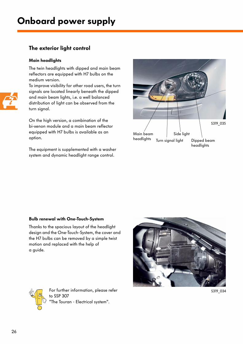
Main headlights
The twin headlights with dipped and main beam reflectors are equipped with H7 bulbs on the medium version.To improve visibility for other road users, the turn signals are located linearly beneath the dipped and main beam lights, i.e. a well balanced distribution of light can be observed from the turn signal.
On the high version, a combination of the bi-xenon module and a main beam reflector equipped with H7 bulbs is available as an option.
The equipment is supplemented with a washer system and dynamic headlight range control.
Bulb renewal with One-Touch-System
Thanks to the spacious layout of the headlight design and the One-Touch-System, the cover and the H7 bulbs can be removed by a simple twist motion and replaced with the help of a guide.
Onboard power supply
S319_035
Main beam headlights Turn signal light
Side light
Dipped beam headlights
S319_034For further information, please refer to SSP 307 "The Touran - Electrical system".
The exterior light control
27
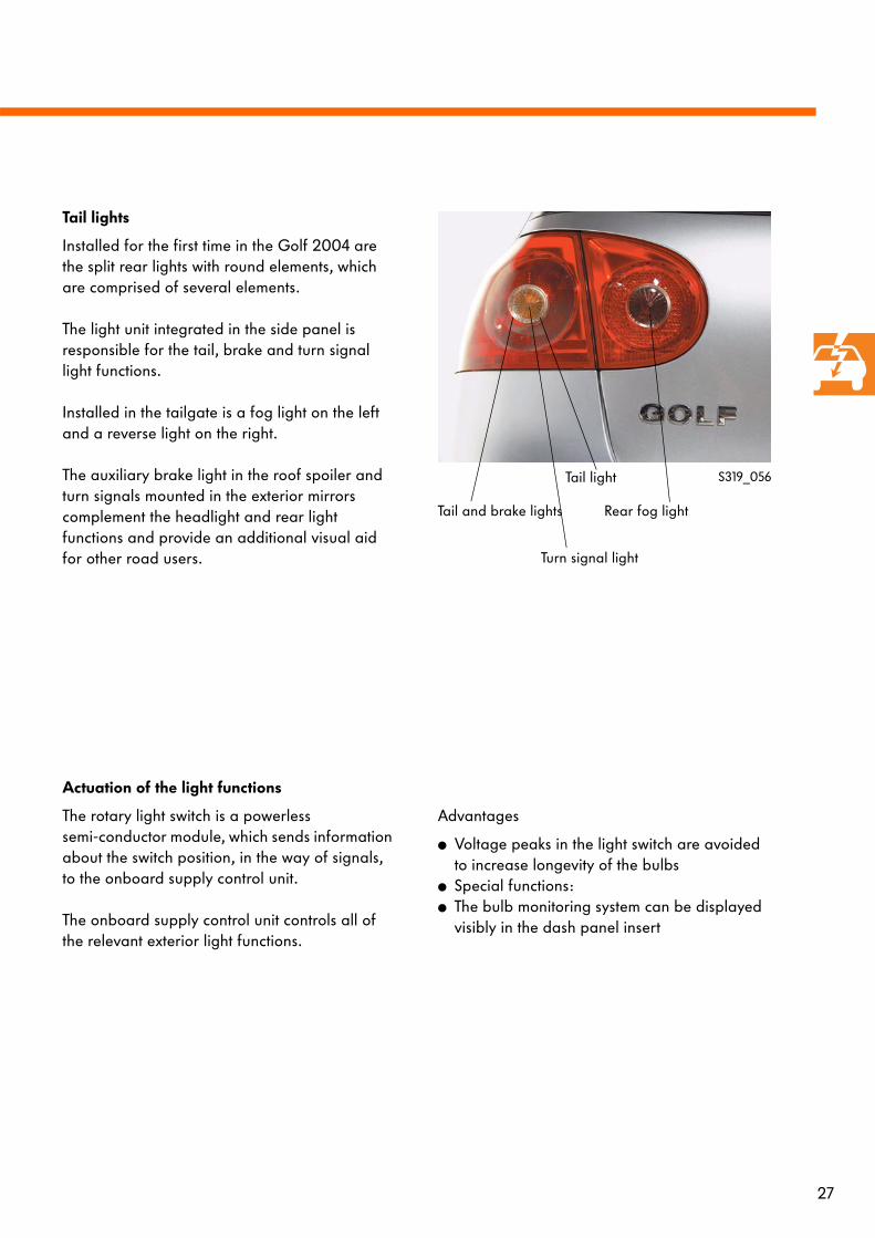
Tail lights
Installed for the first time in the Golf 2004 are the split rear lights with round elements, which are comprised of several elements.
The light unit integrated in the side panel is responsible for the tail, brake and turn signal light functions.
Installed in the tailgate is a fog light on the left and a reverse light on the right.
The auxiliary brake light in the roof spoiler and turn signals mounted in the exterior mirrors complement the headlight and rear light functions and provide an additional visual aid for other road users.
S319_056
Rear fog lightTail and brake lights
Turn signal light
Tail light
Actuation of the light functions
The rotary light switch is a powerless semi-conductor module, which sends information about the switch position, in the way of signals, to the onboard supply control unit.
The onboard supply control unit controls all of the relevant exterior light functions.
Advantages
● Voltage peaks in the light switch are avoided to increase longevity of the bulbs
● Special functions:● The bulb monitoring system can be displayed
visibly in the dash panel insert
28
Coming home
When occupants alight from the vehicle and close the doors, including the tailgate, the vehicle surround lighting is activated for a short period.
Leaving home
After the vehicle has been unlocked using the radio remote control, the area around the vehicle is lit up for a brief period.
If the rotary light switch is in the dipped beam position, the lights are switched off completely once the lighting period has elapsed.
If the rotary light switch is in the side light position, the side light bulbs remain on after the surround lighting is switched off.
Onboard power supply
The convenience lighting
After the lighting period has elapsed or in the event of an interruption, the coming home function cannot be reactivated until the ignition is switched on.
29
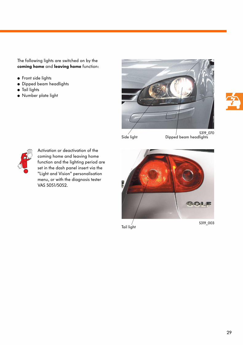
The following lights are switched on by the coming home and leaving home function:
● Front side lights● Dipped beam headlights● Tail lights● Number plate light
S319_070
S319_003
Activation or deactivation of the coming home and leaving home function and the lighting period are set in the dash panel insert via the "Light and Vision" personalisation menu, or with the diagnosis tester VAS 5051/5052.
Side light Dipped beam headlights
Tail light
30
Onboard power supply
The windscreen wiper system
Wiper actuation
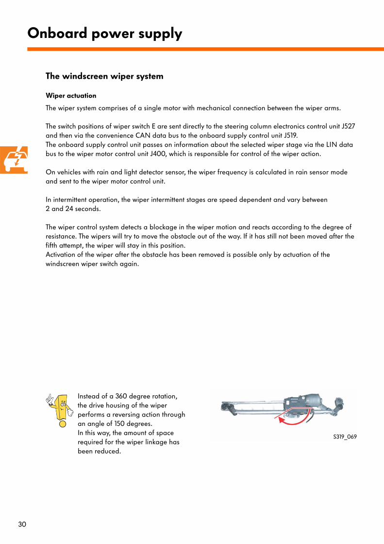
The wiper system comprises of a single motor with mechanical connection between the wiper arms.
The switch positions of wiper switch E are sent directly to the steering column electronics control unit J527 and then via the convenience CAN data bus to the onboard supply control unit J519.The onboard supply control unit passes on information about the selected wiper stage via the LIN data bus to the wiper motor control unit J400, which is responsible for control of the wiper action.
On vehicles with rain and light detector sensor, the wiper frequency is calculated in rain sensor mode and sent to the wiper motor control unit.
In intermittent operation, the wiper intermittent stages are speed dependent and vary between 2 and 24 seconds.
The wiper control system detects a blockage in the wiper motion and reacts according to the degree of resistance. The wipers will try to move the obstacle out of the way. If it has still not been moved after the fifth attempt, the wiper will stay in this position. Activation of the wiper after the obstacle has been removed is possible only by actuation of the windscreen wiper switch again.
Instead of a 360 degree rotation, the drive housing of the wiper performs a reversing action through an angle of 150 degrees.In this way, the amount of space required for the wiper linkage has been reduced.
S319_069
31
D
F266
J533J527
J519
E
J104 G397
J400
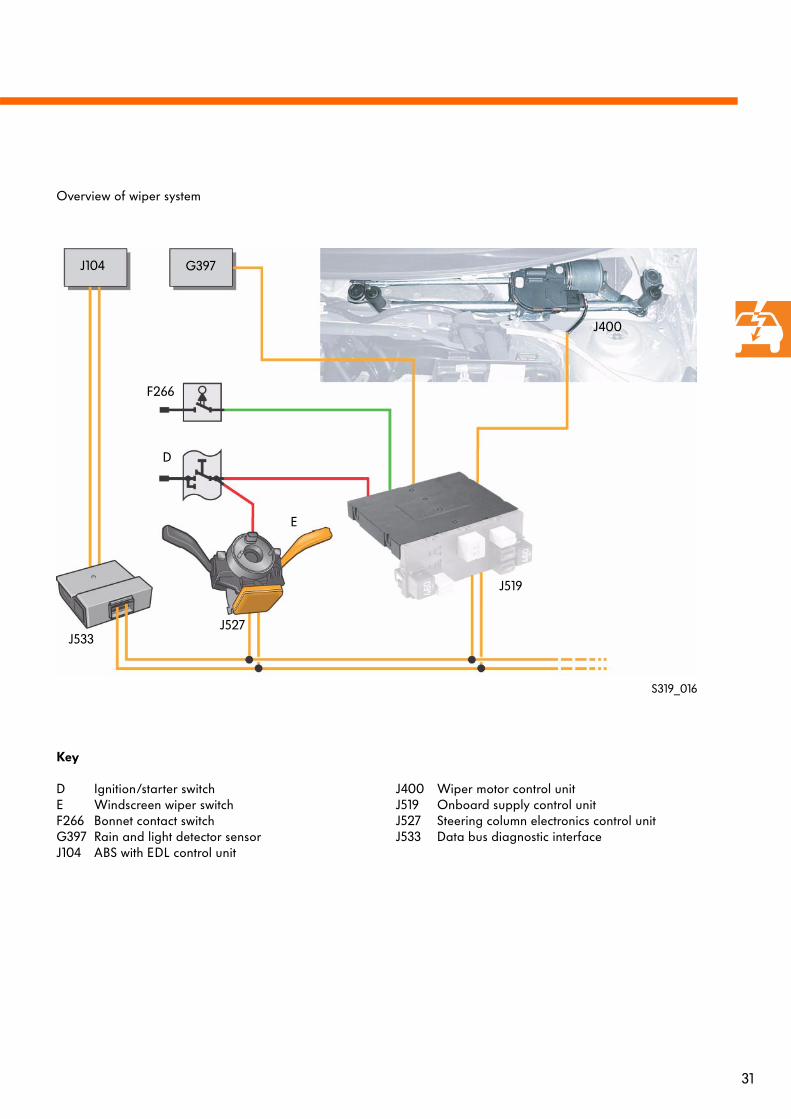
Overview of wiper system
S319_016
Key
D Ignition/starter switchE Windscreen wiper switchF266 Bonnet contact switchG397 Rain and light detector sensorJ104 ABS with EDL control unit
J400 Wiper motor control unitJ519 Onboard supply control unitJ527 Steering column electronics control unitJ533 Data bus diagnostic interface
32
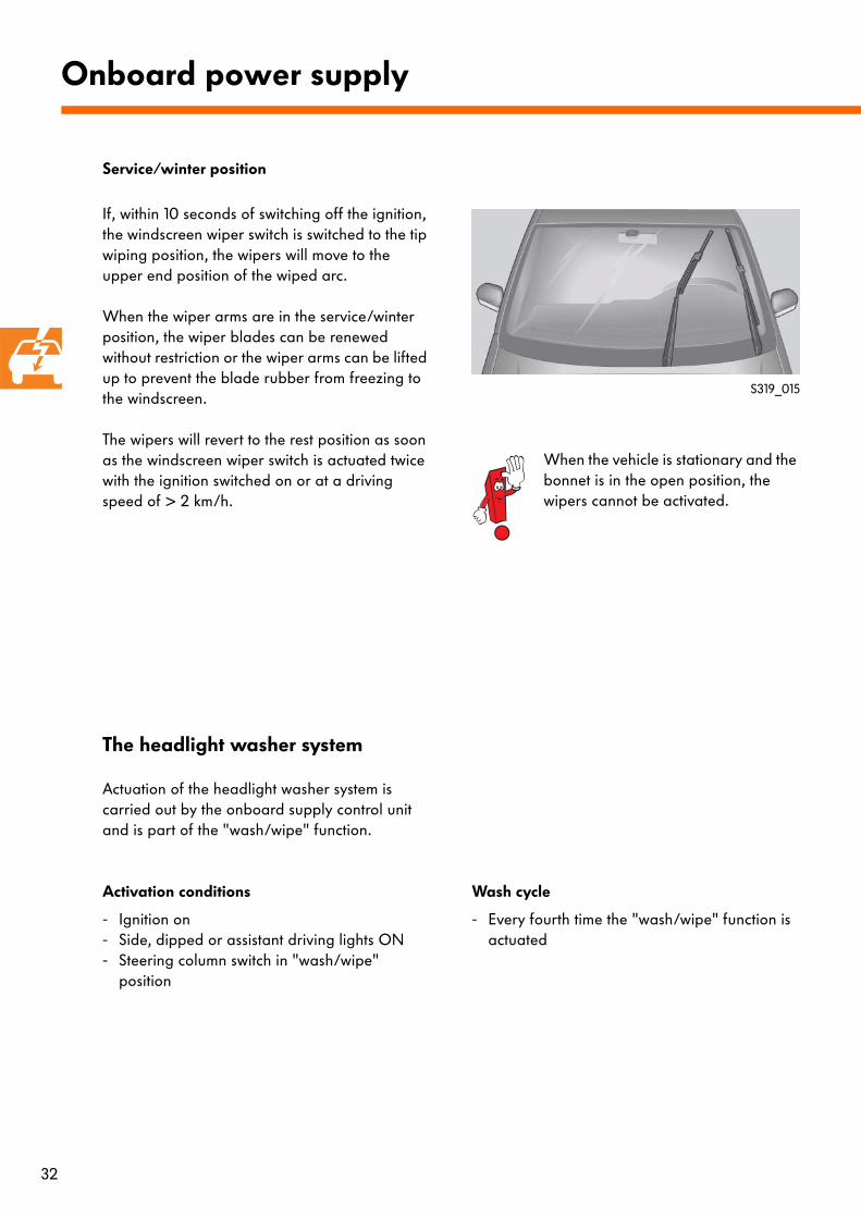
If, within 10 seconds of switching off the ignition, the windscreen wiper switch is switched to the tip wiping position, the wipers will move to the upper end position of the wiped arc.
When the wiper arms are in the service/winter position, the wiper blades can be renewed without restriction or the wiper arms can be lifted up to prevent the blade rubber from freezing to the windscreen.
The wipers will revert to the rest position as soon as the windscreen wiper switch is actuated twice with the ignition switched on or at a driving speed of > 2 km/h.
Onboard power supply
S319_015
When the vehicle is stationary and the bonnet is in the open position, the wipers cannot be activated.
Actuation of the headlight washer system is carried out by the onboard supply control unit and is part of the "wash/wipe" function.
Activation conditions
- Ignition on- Side, dipped or assistant driving lights ON- Steering column switch in "wash/wipe"
position
Wash cycle
- Every fourth time the "wash/wipe" function is actuated
Service/winter position
The headlight washer system
33
- Easy removal/assembly- Improved longevity- Improved anti-crimp and frost protection- Corrugated-type tubes
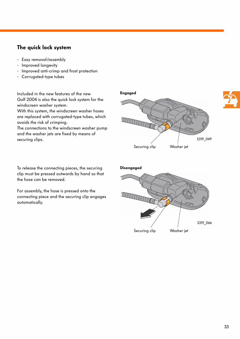
Included in the new features of the new Golf 2004 is also the quick lock system for the windscreen washer system. With this system, the windscreen washer hoses are replaced with corrugated-type tubes, which avoids the risk of crimping. The connections to the windscreen washer pump and the washer jets are fixed by means of securing clips.
To release the connecting pieces, the securing clip must be pressed outwards by hand so that the hose can be removed.
For assembly, the hose is pressed onto the connecting piece and the securing clip engages automatically.
Disengaged
S319_066
The quick lock system
S319_049
Securing clip Washer jet
Engaged
Securing clip Washer jet
34
The control unit with display in the dash panel insert receives its information via the data bus diagnostic interface J533 and the dash panel insert CAN data bus.
Further external sensor signals are sent to the dash panel insert via separate wiring:
● F1 Oil pressure switch● F34 Front left brake pad wear warning contact● G17Ambient temperature sender,
located in bumper● G32Coolant shortage indicator sender● G33Windscreen washer fluid level sender
(optional)● G34Front left brake pad wear sender● J538Fuel pump control unit
Diagnosis
Diagnosis of the control unit with display in the dash panel insert is carried out using the diagnosis tester VAS 5051/5052 via the CAN data bus.
Furthermore, the dash panel insert control unit is capable of self-monitoring. If a fault occurs, this will be shown in the display by the letters "def".
Onboard power supply
Control unit with display in dash panel insert J285
Versions
The sections in the display vary depending on the three versions of dash panel insert:
● Lowline version● Midline version● Highline version
LED warning lamps only appear in the upper area on Lowline and Midline versions.
For further information, please refer to SSP 307 "The Touran - Electrical system".
35
Immobiliser IV
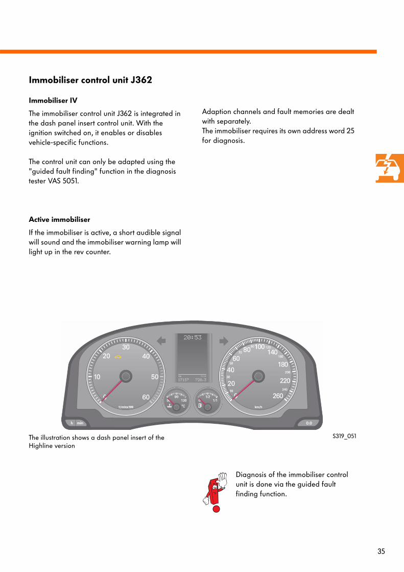
The immobiliser control unit J362 is integrated in the dash panel insert control unit. With the ignition switched on, it enables or disables vehicle-specific functions.
The control unit can only be adapted using the "guided fault finding" function in the diagnosis tester VAS 5051.
Active immobiliser
If the immobiliser is active, a short audible signal will sound and the immobiliser warning lamp will light up in the rev counter.
Adaption channels and fault memories are dealt with separately. The immobiliser requires its own address word 25 for diagnosis.
Diagnosis of the immobiliser control unit is done via the guided fault finding function.
S319_051
Immobiliser control unit J362
The illustration shows a dash panel insert of the Highline version
36
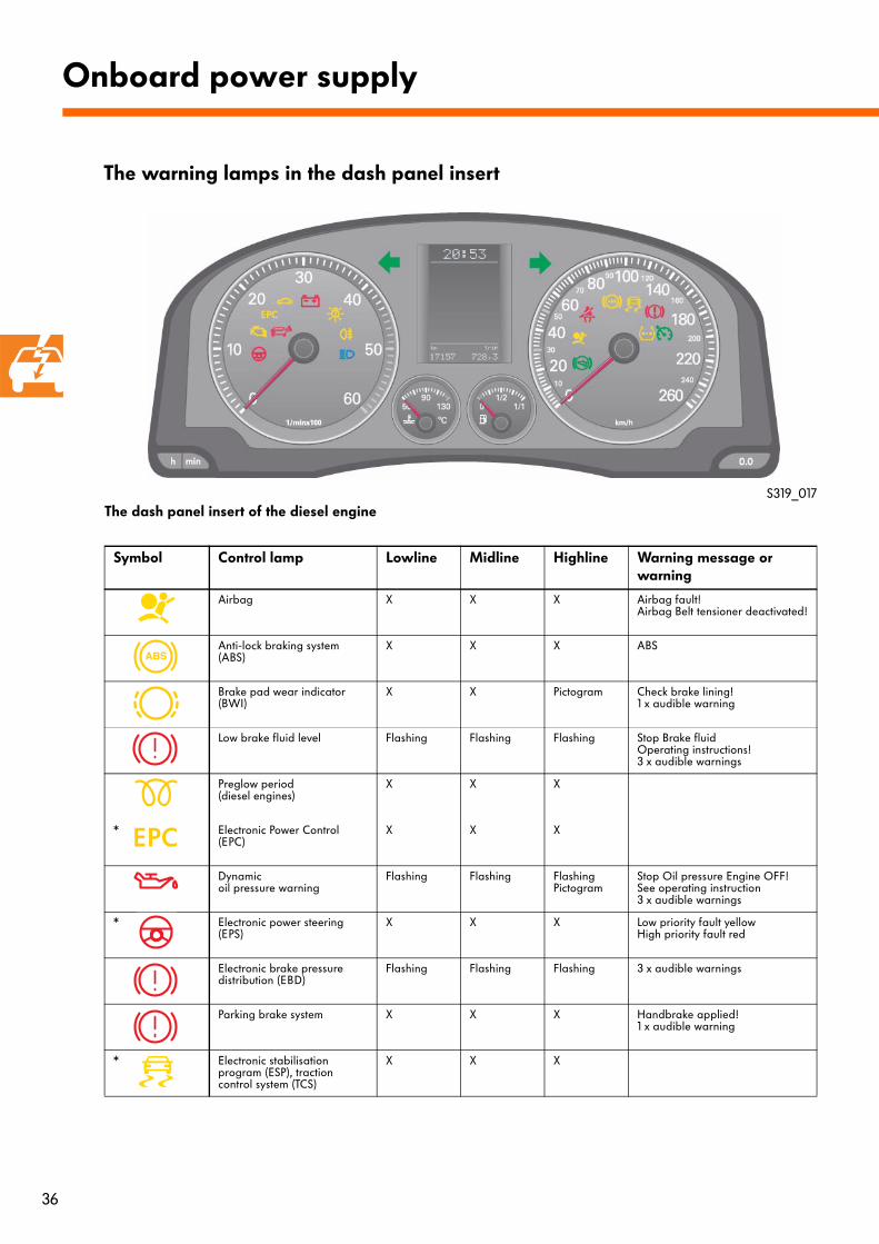
The dash panel insert of the diesel engine
Symbol Control lamp Lowline Midline Highline Warning message or warning
Airbag X X X Airbag fault!Airbag Belt tensioner deactivated!
Anti-lock braking system (ABS)
X X X ABS
Brake pad wear indicator (BWI)
X X Pictogram Check brake lining!1 x audible warning
Low brake fluid level Flashing Flashing Flashing Stop Brake fluid Operating instructions!3 x audible warnings
Preglow period (diesel engines)
X X X
* Electronic Power Control (EPC)
X X X
Dynamicoil pressure warning
Flashing Flashing Flashing Pictogram
Stop Oil pressure Engine OFF!See operating instruction 3 x audible warnings
* Electronic power steering (EPS)
X X X Low priority fault yellowHigh priority fault red
Electronic brake pressure distribution (EBD)
Flashing Flashing Flashing 3 x audible warnings
Parking brake system X X X Handbrake applied!1 x audible warning
* Electronic stabilisation program (ESP), traction control system (TCS)
X X X
Onboard power supply
The warning lamps in the dash panel insert
S319_017
37
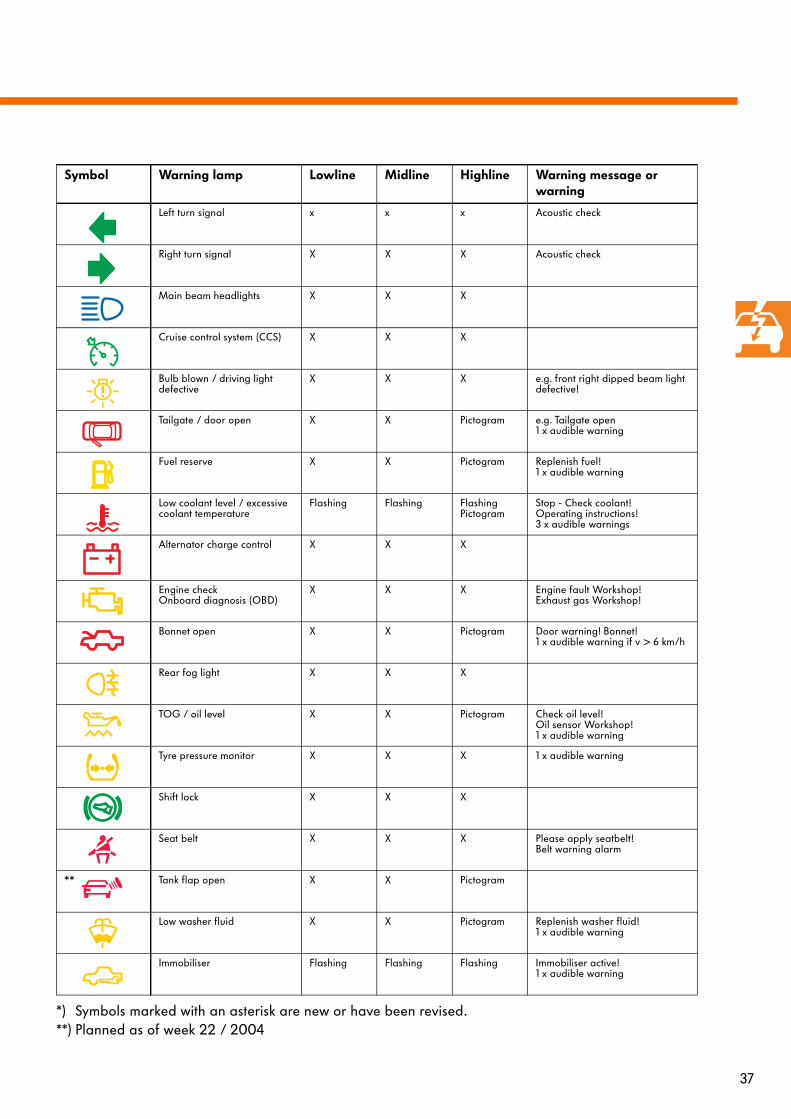
Symbol Warning lamp Lowline Midline Highline Warning message or warning
Left turn signal x x x Acoustic check
Right turn signal X X X Acoustic check
Main beam headlights X X X
Cruise control system (CCS) X X X
Bulb blown / driving light defective
X X X e.g. front right dipped beam light defective!
Tailgate / door open X X Pictogram e.g. Tailgate open1 x audible warning
Fuel reserve X X Pictogram Replenish fuel!1 x audible warning
Low coolant level / excessive coolant temperature
Flashing Flashing FlashingPictogram
Stop - Check coolant!Operating instructions!3 x audible warnings
Alternator charge control X X X
Engine check Onboard diagnosis (OBD)
X X X Engine fault Workshop!Exhaust gas Workshop!
Bonnet open X X Pictogram Door warning! Bonnet!1 x audible warning if v > 6 km/h
Rear fog light X X X
TOG / oil level X X Pictogram Check oil level!Oil sensor Workshop!1 x audible warning
Tyre pressure monitor X X X 1 x audible warning
Shift lock X X X
Seat belt X X X Please apply seatbelt!Belt warning alarm
** Tank flap open X X Pictogram
Low washer fluid X X Pictogram Replenish washer fluid!1 x audible warning
Immobiliser Flashing Flashing Flashing Immobiliser active!1 x audible warning
*) Symbols marked with an asterisk are new or have been revised.**) Planned as of week 22 / 2004
38
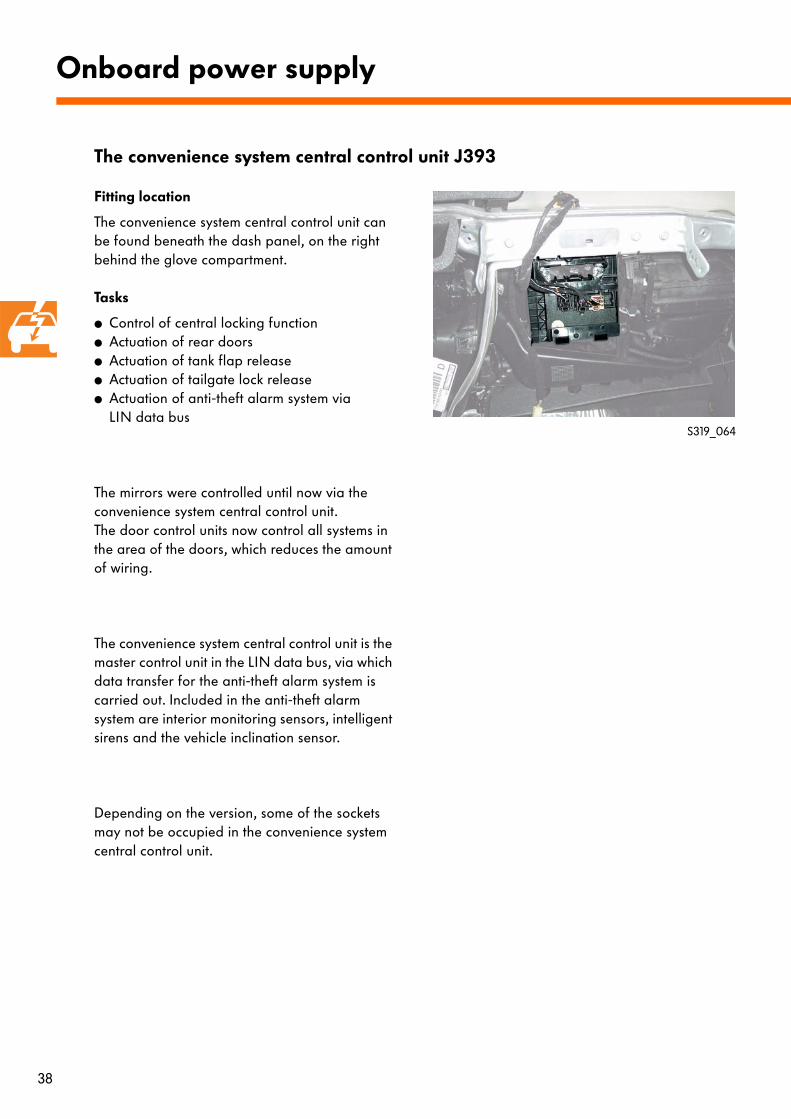
Fitting location
The convenience system central control unit can be found beneath the dash panel, on the right behind the glove compartment.
Tasks
● Control of central locking function● Actuation of rear doors● Actuation of tank flap release● Actuation of tailgate lock release● Actuation of anti-theft alarm system via
LIN data bus
The mirrors were controlled until now via the convenience system central control unit. The door control units now control all systems in the area of the doors, which reduces the amount of wiring.
The convenience system central control unit is the master control unit in the LIN data bus, via which data transfer for the anti-theft alarm system is carried out. Included in the anti-theft alarm system are interior monitoring sensors, intelligent sirens and the vehicle inclination sensor.
Depending on the version, some of the sockets may not be occupied in the convenience system central control unit.
Onboard power supply
The convenience system central control unit J393
S319_064
39
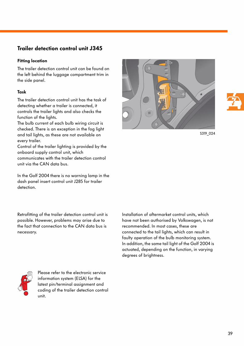
Fitting location
The trailer detection control unit can be found on the left behind the luggage compartment trim in the side panel.
Task
The trailer detection control unit has the task of detecting whether a trailer is connected, it controls the trailer lights and also checks the function of the lights. The bulb current of each bulb wiring circuit is checked. There is an exception in the fog light and tail lights, as these are not available on every trailer. Control of the trailer lighting is provided by the onboard supply control unit, which communicates with the trailer detection control unit via the CAN data bus.
In the Golf 2004 there is no warning lamp in the dash panel insert control unit J285 for trailer detection.
Trailer detection control unit J345
S319_024
Retrofitting of the trailer detection control unit is possible. However, problems may arise due to the fact that connection to the CAN data bus is necessary.
Installation of aftermarket control units, which have not been authorised by Volkswagen, is not recommended. In most cases, these are connected to the tail lights, which can result in faulty operation of the bulb monitoring system. In addition, the same tail light of the Golf 2004 is actuated, depending on the function, in varying degrees of brightness.
Please refer to the electronic service information system (ELSA) for the latest pin/terminal assignment and coding of the trailer detection control unit.
40
J285
J533
J104
The tyre pressure monitoring system is a software module in the ABS control unit, which detects slow and gradual loss of air from the tyres. From current ABS and ESP data (wheel speed, current vehicle status), it filters out fine changes and compares the information with reference data.
The circumference of a tyre can change depending on the amount of air inside. If the circumference changes beyond a specified degree, the tyre pressure monitoring system will detect pressure loss.
If pressure loss is detected, the driver will be shown a permanent warning by the tyre pressure monitor warning lamp in the speedometer of the dash panel insert and one audible warning will sound when the ignition is switched on.
The warning will not be reset until the driver starts a new calibration procedure.
Tyre pressure monitor
S319_018
● Evaluation of data is interrupted during fast cornering, on uneven road surfaces, during braking and when the vehicle is driven up or down steep gradients. In these situations, tyre pressure loss cannot be detected.
● Each time the tyre pressure is altered or if a tyre has been changed, the driver must carry out a calibration procedure to prevent false warnings that may occur from old reference data.Even in the event of repair work on the running gear, the calibration procedure should be carried out by the workshop and the driver informed of this fact.
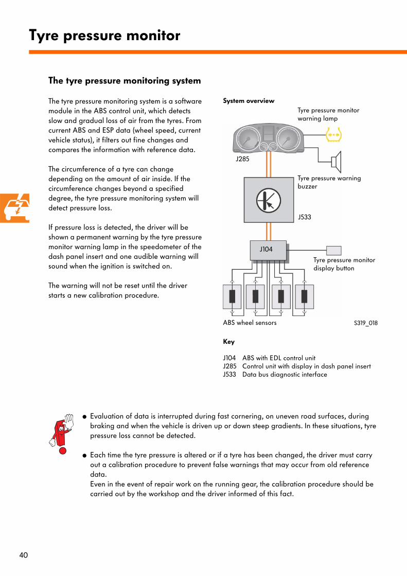
System overview
Tyre pressure monitor display button
Tyre pressure warning buzzer
Tyre pressure monitor warning lamp
ABS wheel sensors
Key
J104 ABS with EDL control unitJ285 Control unit with display in dash panel insertJ533 Data bus diagnostic interface
The tyre pressure monitoring system
41
Calibration
Since the tyre characteristics can change, a calibration procedure must be performed each time the tyre pressure is altered, or when a wheel is changed, to allow new reference data to be calculated.
Calibration procedure
To start the calibration procedure, the tyre pressure monitor display button must be pressed for 2 seconds. The warning lamp in the speedometer will light up while the button is pressed and will go out after 2 seconds. In addition, a confirmation signal will sound.
As the vehicle is driven normally, the system will calibrate itself to the set tyre pressures and type of tyres. Tyre pressure monitoring will gradually take over as the calibration procedure nears the end. It takes just a few minutes before basic monitoring can start, based on the figures analysed by the system.
System fault
In the event of a fault in the ABS with EDL control unit, tyre pressure monitoring will be stopped and the tyre pressure monitor warning lamp will light up in the speedometer.
Diagnosis
Diagnosis is carried out using the diagnosis tester VAS 5051/5052 via the guided fault finding function in the ABS with EDL control unit J104.
42
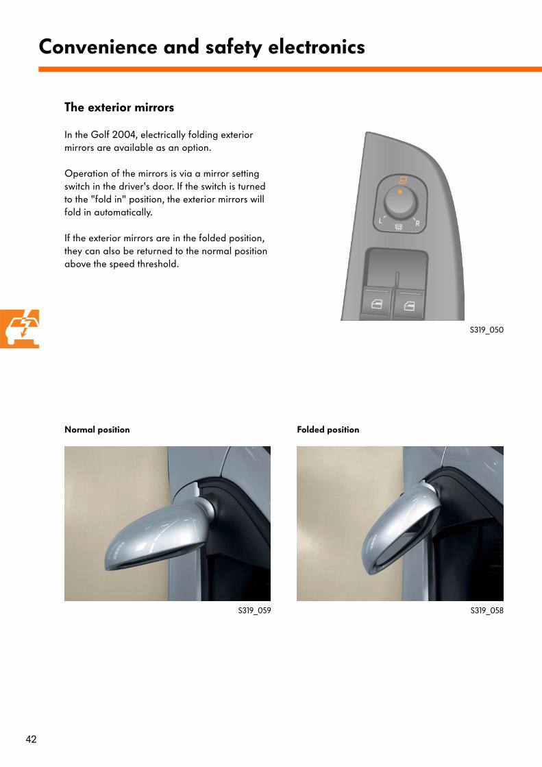
In the Golf 2004, electrically folding exterior mirrors are available as an option.
Operation of the mirrors is via a mirror setting switch in the driver's door. If the switch is turned to the "fold in" position, the exterior mirrors will fold in automatically.
If the exterior mirrors are in the folded position, they can also be returned to the normal position above the speed threshold.
Convenience and safety electronics
S319_050
S319_058S319_059
Normal position Folded position
The exterior mirrors
43
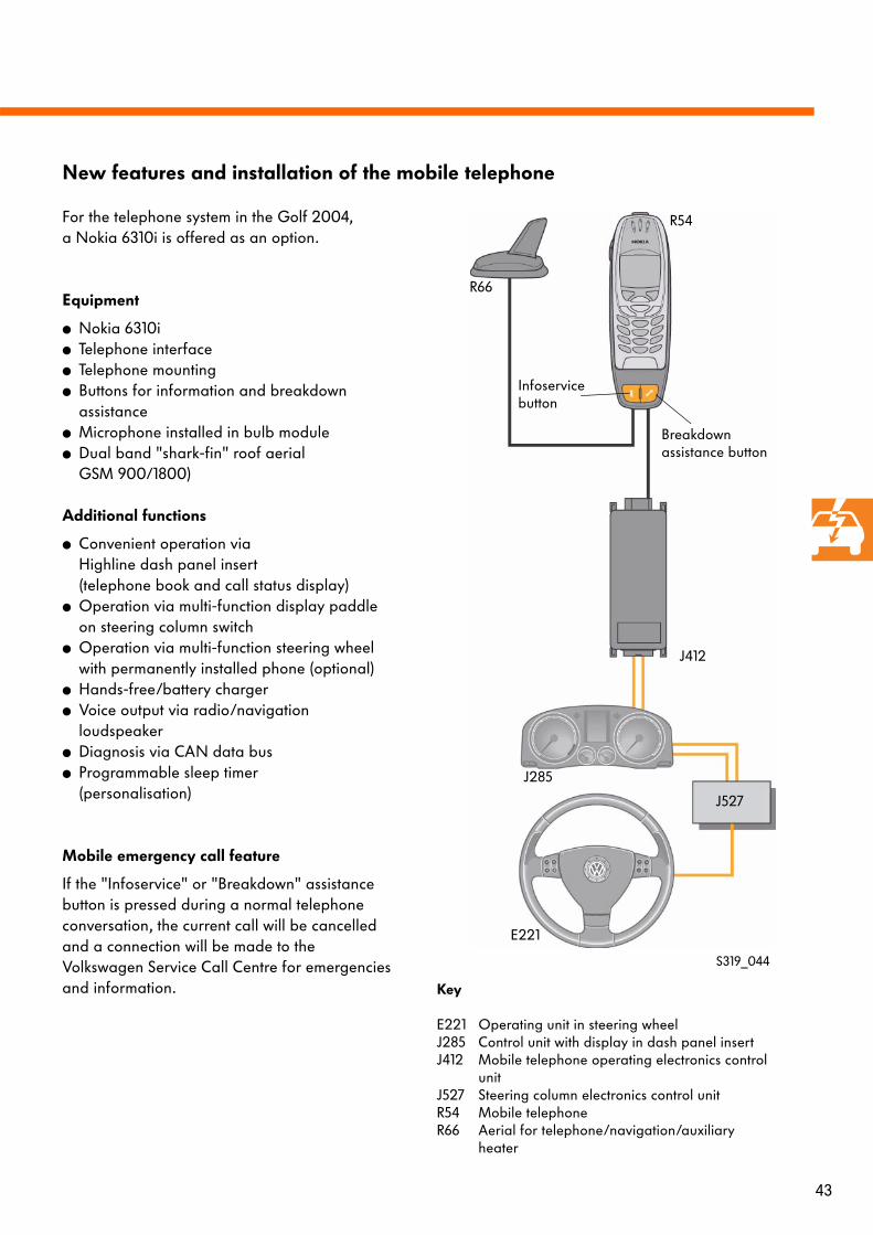
For the telephone system in the Golf 2004, a Nokia 6310i is offered as an option.
Equipment
● Nokia 6310i● Telephone interface● Telephone mounting● Buttons for information and breakdown
assistance● Microphone installed in bulb module ● Dual band "shark-fin" roof aerial
GSM 900/1800)
Additional functions
● Convenient operation via Highline dash panel insert(telephone book and call status display)
● Operation via multi-function display paddle on steering column switch
● Operation via multi-function steering wheel with permanently installed phone (optional)
● Hands-free/battery charger● Voice output via radio/navigation
loudspeaker● Diagnosis via CAN data bus● Programmable sleep timer
(personalisation)
Mobile emergency call feature
If the "Infoservice" or "Breakdown" assistance button is pressed during a normal telephone conversation, the current call will be cancelled and a connection will be made to the Volkswagen Service Call Centre for emergencies and information.
R66
R54
J412
J285
E221
J527
New features and installation of the mobile telephone
S319_044
Key
E221 Operating unit in steering wheelJ285 Control unit with display in dash panel insertJ412 Mobile telephone operating electronics control
unitJ527 Steering column electronics control unitR54 Mobile telephoneR66 Aerial for telephone/navigation/auxiliary
heater
Infoservice button
Breakdown assistance button
44
J527
J285
J533
J519 J393 J364
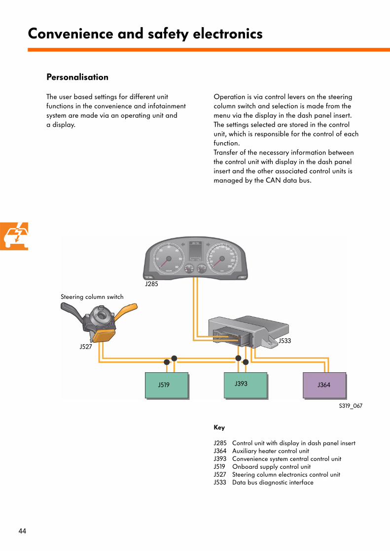
The user based settings for different unit functions in the convenience and infotainment system are made via an operating unit and a display.
Operation is via control levers on the steering column switch and selection is made from the menu via the display in the dash panel insert. The settings selected are stored in the control unit, which is responsible for the control of each function.Transfer of the necessary information between the control unit with display in the dash panel insert and the other associated control units is managed by the CAN data bus.
Convenience and safety electronics
Key
J285 Control unit with display in dash panel insertJ364 Auxiliary heater control unitJ393 Convenience system central control unitJ519 Onboard supply control unitJ527 Steering column electronics control unitJ533 Data bus diagnostic interface
S319_067
Steering column switch
Personalisation
45
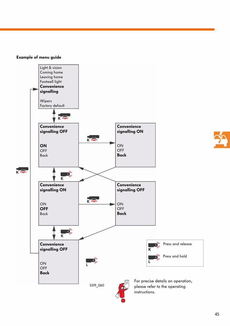
Example of menu guide
Light & visionComing homeLeaving homeFootwell lightConvenience signalling
WipersFactory default
Convenience signalling OFF
ONOFFBack
Convenience signalling ON
ONOFFBack
Convenience signalling OFF
ONOFFBack
Convenience signalling ON
ONOFF Back
Convenience signalling OFF
ONOFFBack
Press and release
Press and hold
For precise details on operation, please refer to the operating instructions.
S319_060
46
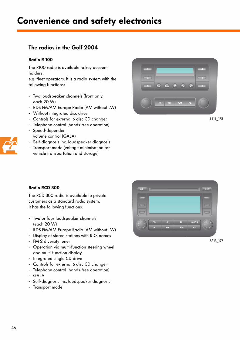
Radio R 100
The R100 radio is available to key account holders,e.g. fleet operators. It is a radio system with the following functions:
- Two loudspeaker channels (front only, each 20 W)
- RDS FM/AM Europe Radio (AM without LW)- Without integrated disc drive- Controls for external 6 disc CD changer- Telephone control (hands-free operation) - Speed-dependent
volume control (GALA)- Self-diagnosis inc. loudspeaker diagnosis- Transport mode (voltage minimisation for
vehicle transportation and storage)
Radio RCD 300
The RCD 300 radio is available to private customers as a standard radio system. It has the following functions:
- Two or four loudspeaker channels (each 20 W)
- RDS FM/AM Europe Radio (AM without LW)- Display of stored stations with RDS names- FM 2 diversity tuner- Operation via multi-function steering wheel
and multi-function display- Integrated single CD drive- Controls for external 6 disc CD changer- Telephone control (hands-free operation)- GALA- Self-diagnosis inc. loudspeaker diagnosis- Transport mode
Convenience and safety electronics
S318_175
S318_177
The radios in the Golf 2004
47
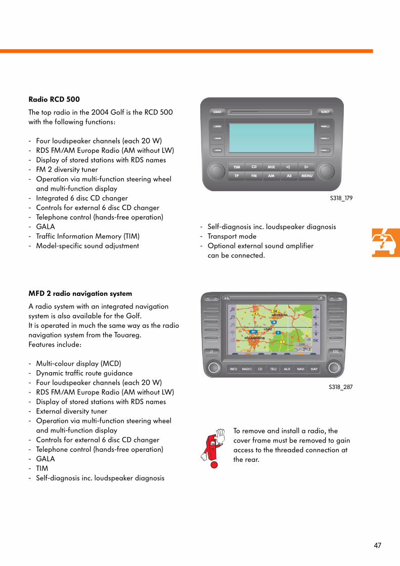
Radio RCD 500
The top radio in the 2004 Golf is the RCD 500 with the following functions:
- Four loudspeaker channels (each 20 W)- RDS FM/AM Europe Radio (AM without LW)- Display of stored stations with RDS names- FM 2 diversity tuner- Operation via multi-function steering wheel
and multi-function display- Integrated 6 disc CD changer- Controls for external 6 disc CD changer- Telephone control (hands-free operation)- GALA- Traffic Information Memory (TIM)- Model-specific sound adjustment
MFD 2 radio navigation system
A radio system with an integrated navigation system is also available for the Golf. It is operated in much the same way as the radio navigation system from the Touareg. Features include:
- Multi-colour display (MCD)- Dynamic traffic route guidance- Four loudspeaker channels (each 20 W)- RDS FM/AM Europe Radio (AM without LW)- Display of stored stations with RDS names- External diversity tuner- Operation via multi-function steering wheel
and multi-function display- Controls for external 6 disc CD changer- Telephone control (hands-free operation)- GALA- TIM- Self-diagnosis inc. loudspeaker diagnosis
- Self-diagnosis inc. loudspeaker diagnosis- Transport mode- Optional external sound amplifier
can be connected.
S318_179
S318_287
To remove and install a radio, the cover frame must be removed to gain access to the threaded connection at the rear.
48
+ -
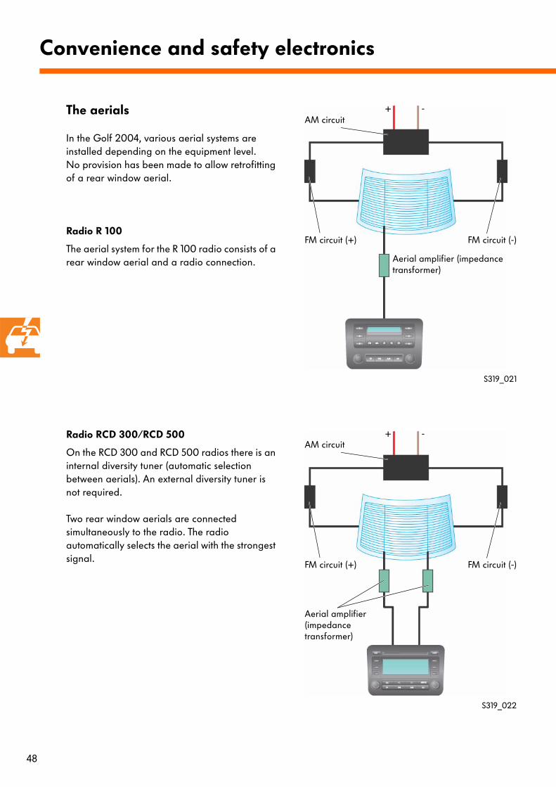
The aerials
In the Golf 2004, various aerial systems are installed depending on the equipment level. No provision has been made to allow retrofitting of a rear window aerial.
Radio R 100
The aerial system for the R 100 radio consists of a rear window aerial and a radio connection.
Radio RCD 300/RCD 500
On the RCD 300 and RCD 500 radios there is an internal diversity tuner (automatic selection between aerials). An external diversity tuner is not required.
Two rear window aerials are connected simultaneously to the radio. The radio automatically selects the aerial with the strongest signal.
Convenience and safety electronics
S319_021
S319_022
Aerial amplifier (impedance transformer)
AM circuit+ -
Aerial amplifier (impedance transformer)
FM circuit (+) FM circuit (-)
AM circuit
FM circuit (+) FM circuit (-)
49
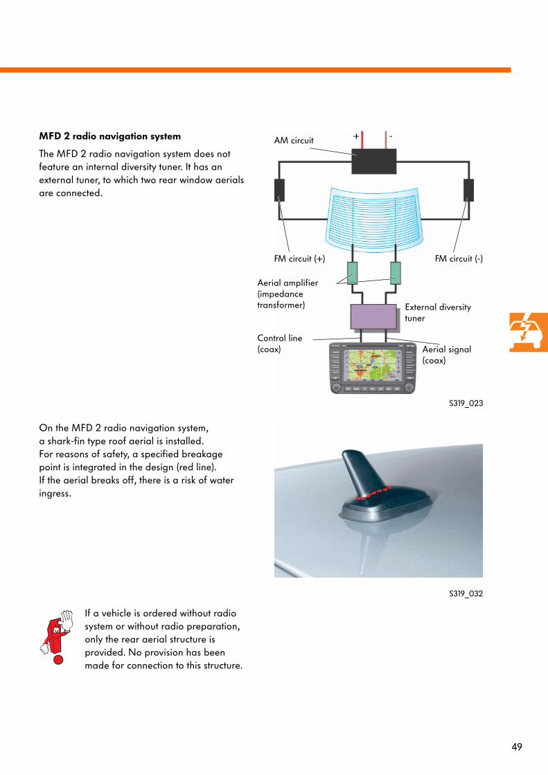
+ -MFD 2 radio navigation system
The MFD 2 radio navigation system does not feature an internal diversity tuner. It has an external tuner, to which two rear window aerials are connected.
On the MFD 2 radio navigation system, a shark-fin type roof aerial is installed. For reasons of safety, a specified breakage point is integrated in the design (red line). If the aerial breaks off, there is a risk of water ingress.
S319_023
If a vehicle is ordered without radio system or without radio preparation, only the rear aerial structure is provided. No provision has been made for connection to this structure.
S319_032
Aerial amplifier (impedance transformer)
Control line (coax)
AM circuit
FM circuit (+) FM circuit (-)
External diversity tuner
Aerial signal (coax)
50
J412 J503 R
J285
J527
J533
R54
R66
15
30
E221
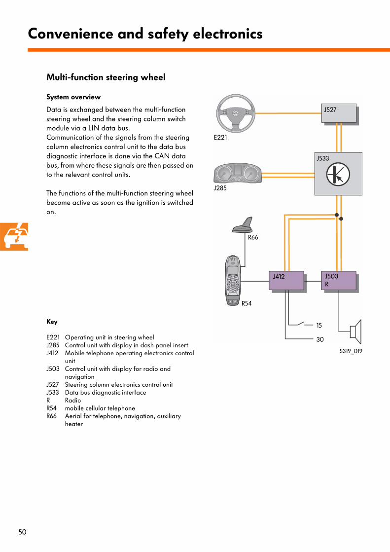
System overview
Data is exchanged between the multi-function steering wheel and the steering column switch module via a LIN data bus.Communication of the signals from the steering column electronics control unit to the data bus diagnostic interface is done via the CAN data bus, from where these signals are then passed on to the relevant control units.
The functions of the multi-function steering wheel become active as soon as the ignition is switched on.
Convenience and safety electronics
S319_019
Key
E221 Operating unit in steering wheelJ285 Control unit with display in dash panel insertJ412 Mobile telephone operating electronics control
unitJ503 Control unit with display for radio and
navigationJ527 Steering column electronics control unitJ533 Data bus diagnostic interfaceR RadioR54 mobile cellular telephone R66 Aerial for telephone, navigation, auxiliary
heater
Multi-function steering wheel
51
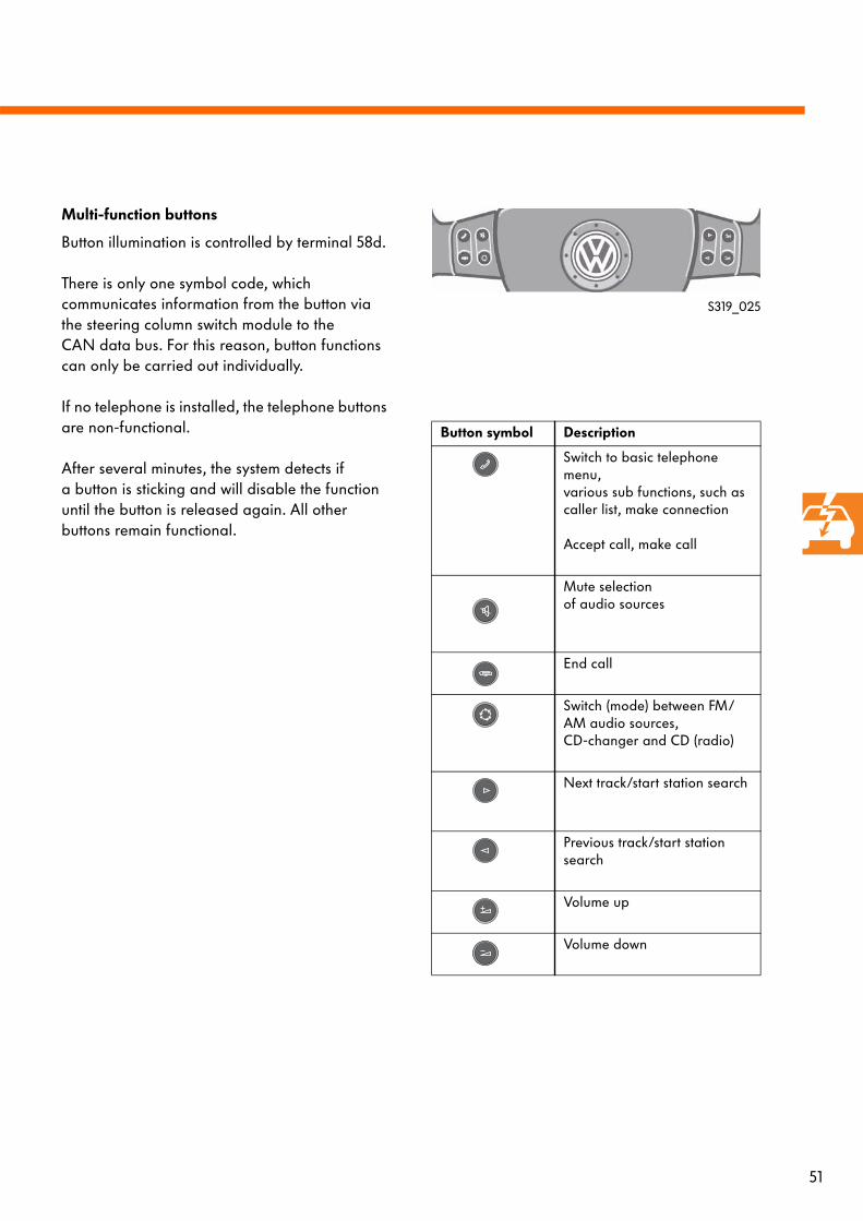
Multi-function buttons
Button illumination is controlled by terminal 58d.
There is only one symbol code, which communicates information from the button via the steering column switch module to the CAN data bus. For this reason, button functions can only be carried out individually.
If no telephone is installed, the telephone buttons are non-functional.
After several minutes, the system detects if a button is sticking and will disable the function until the button is released again. All other buttons remain functional.
Button symbol Description
Switch to basic telephone menu, various sub functions, such as caller list, make connection
Accept call, make call
Mute selection of audio sources
End call
Switch (mode) between FM/AM audio sources, CD-changer and CD (radio)
Next track/start station search
Previous track/start station search
Volume up
Volume down
S319_025
52
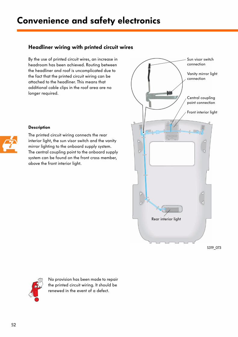
By the use of printed circuit wires, an increase in headroom has been achieved. Routing between the headliner and roof is uncomplicated due to the fact that the printed circuit wiring can be attached to the headliner. This means that additional cable clips in the roof area are no longer required.
Description
The printed circuit wiring connects the rear interior light, the sun visor switch and the vanity mirror lighting to the onboard supply system. The central coupling point to the onboard supply system can be found on the front cross member, above the front interior light.
Convenience and safety electronics
No provision has been made to repair the printed circuit wiring. It should be renewed in the event of a defect.
Headliner wiring with printed circuit wires
S319_073
Rear interior light
Sun visor switch connection
Vanity mirror light connection
Central coupling point connection
Front interior light
53
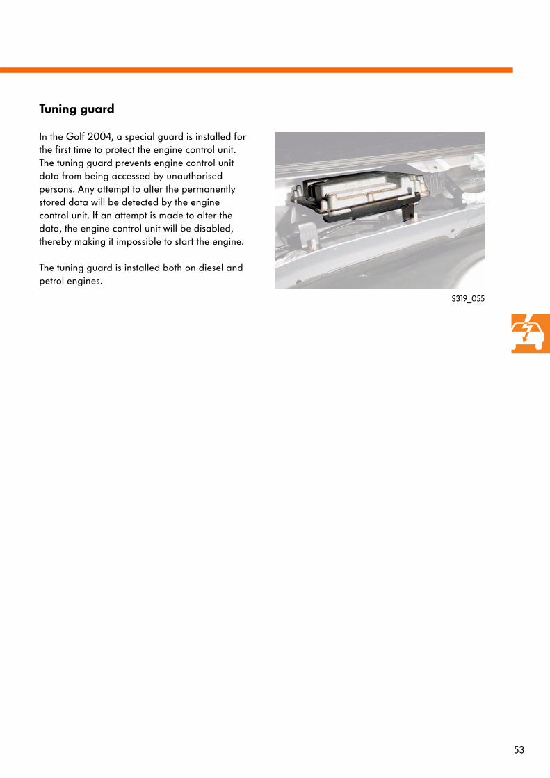
In the Golf 2004, a special guard is installed for the first time to protect the engine control unit. The tuning guard prevents engine control unit data from being accessed by unauthorised persons. Any attempt to alter the permanently stored data will be detected by the engine control unit. If an attempt is made to alter the data, the engine control unit will be disabled, thereby making it impossible to start the engine.
The tuning guard is installed both on diesel and petrol engines.
S319_055
Tuning guard
54
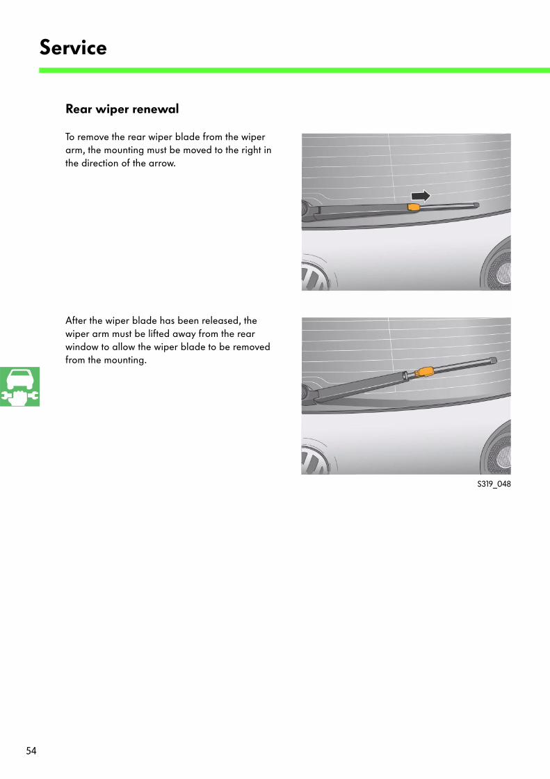
Rear wiper renewal
To remove the rear wiper blade from the wiper arm, the mounting must be moved to the right in the direction of the arrow.
After the wiper blade has been released, the wiper arm must be lifted away from the rear window to allow the wiper blade to be removed from the mounting.
Service
S319_048

55
56
1. Where can the data bus diagnostic interface J533 be found?
a) On the right beneath the dash panel, behind the glove compartment
b) In the dash panel insert
c) Beneath the dash panel, above the accelerator pedal
2. What are the advantages of the powerless semi-conductor rotary light switch?
a) Bulb replacement function via control from onboard supply control unit
b) Coming home and leaving home function
c) Increase in bulb longevity
d) Activation of bulb failure warning lamp in dash panel insert
3. What systems are switched off in transport mode for transportation of the vehicle?
a) Auxiliary heater telestart receiver, radio remote control, radio, interior monitoring, interior light, vehicle inclination sensor, alighting aids
b) Auxiliary heater telestart receiver, radio remote control, radio, interior monitoring, fog light, interior light, vehicle inclination sensor, alighting aids
c) Vehicle inclination sensor, driving lights, radio remote control, auxiliary heater telestart receiver, interior monitoring, interior light, alighting aids, radio
Test yourself
57
4. Which control units are responsible for tyre pressure monitoring?
a) Control unit in dash panel insert J285, data bus diagnostic interface J534 and ABS with EDL control unit J104
b) ABS with EDL control unit, data bus diagnostic interface, dash panel insert control unit and tyre pressure monitor display control unit
a) Data bus diagnostic interface J533, ABS with EDL control unit J104 and control unit with display in dash panel insert J285
5. Which lights are joined by the printed circuit wiring?
a) Radio and heater display
b) Ashtray lights and cockpit illumination
c) Reading lamps and interior lights
d) Vanity mirror light and interior lights
58
Test yourselfAnswers:1. c 2. c, d 3. a4. c5. b, c, d

For internal use only © AG, Wolfsburg VK 36, Service Training
All rights and the right to make technical alterations reserved
000.2811.40.20 Technical status 10/03
❀ This paper was manufactured from pulp that
was bleached without the use of chlorine.
319