Embed Size (px)
Citation preview
1
On Using Virtual-Circuit Networks for FileTransfersMark McGinley
Department of Computer EngineeringUniversity of Virginia
Email: [email protected]
I. INTRODUCTION
It has become clear that widespread collaboration in the scientific community, which can increasingly becharacterized by geographically distributed and large-scale projects, requires predictable network service[1]. Predictable network service needed by applications such as large file transfers, remote visualization,and remote instrumentation can only be offered on connection-oriented networks. Circuit-switched andvirtual-circuit networks offer connection-oriented services1. Significant work in the CHEETAH project [2]focused on various problems related to using circuit-switched networks for file transfers. (e.g., [3]–[7]).In this work, the focus is on using virtual-circuit networks for file transfers.
There are four compelling reasons to study the use of virtual circuits for file transfers.1) By using a single substrate of packet switches, a network could offer both connection-oriented (with
virtual circuits) and connectionless services. The availability of both connection-oriented and connec-tionless services allows a file transfer to use the service appropriate to its size. Small file transfers useconnectionless service to avoid the setup-delay overhead cost associated with connection-orientedservice, while large file transfers use connection-oriented service if rate guarantees are desired.
2) The pervasive technology of end hosts’ network interface cards is packet based, i.e. Ethernet, whichis a compelling reason to address problems in the packet-switched network context.
3) There is a flexibility advantage with virtual circuits when compared to circuits. Circuit switchesnecessarily have a base crossconnect rate, which is the unit rate of the demultiplexed streams. Whilethere may be technological limits on how many virtual circuits can be supported with guaranteedbandwidth on a virtual-circuit switch, theoretically there is more flexibility with respect to adjustingthe number of admitted calls and the corresponding bandwidth allocations.
4) Internet2 [8] and the Department of Energy’s Energy Sciences Network (ESnet) [9] have respondedto a need for dedicated high-bandwidth circuits/VCs by deploying the Dynamic Circuit (DC)Network [10] and the Science Data Network (SDN) [11], respectively. Virtual circuits are usedin both networks.
This work addresses three problems related to supporting file transfers on virtual-circuit networks.First, this work answers the question of what transport protocol is appropriate for use in virtual circuits.
Data-plane functions such as policing and scheduling are used to ensure rate guarantees on virtual circuits.As the data-plane characteristics of virtual circuits with rate guarantees are different from the data-planecharacteristics of connectionless networks for which today’s transport protocols have been designed, anew transport protocol is required for rate-guaranteed virtual circuits. Section II describes the design,implementation, and experimentation work planned to develop a novel transport protocol for use invirtual-circuit networks.
1As opposed to connectionless service typified by the Internet. The differentiating function between connection-oriented and connectionlessnetworks is the presence or absence of admission control for link bandwidth. This usage of the term “connection-oriented” is not to beconfused with the connection-oriented service of TCP.
2
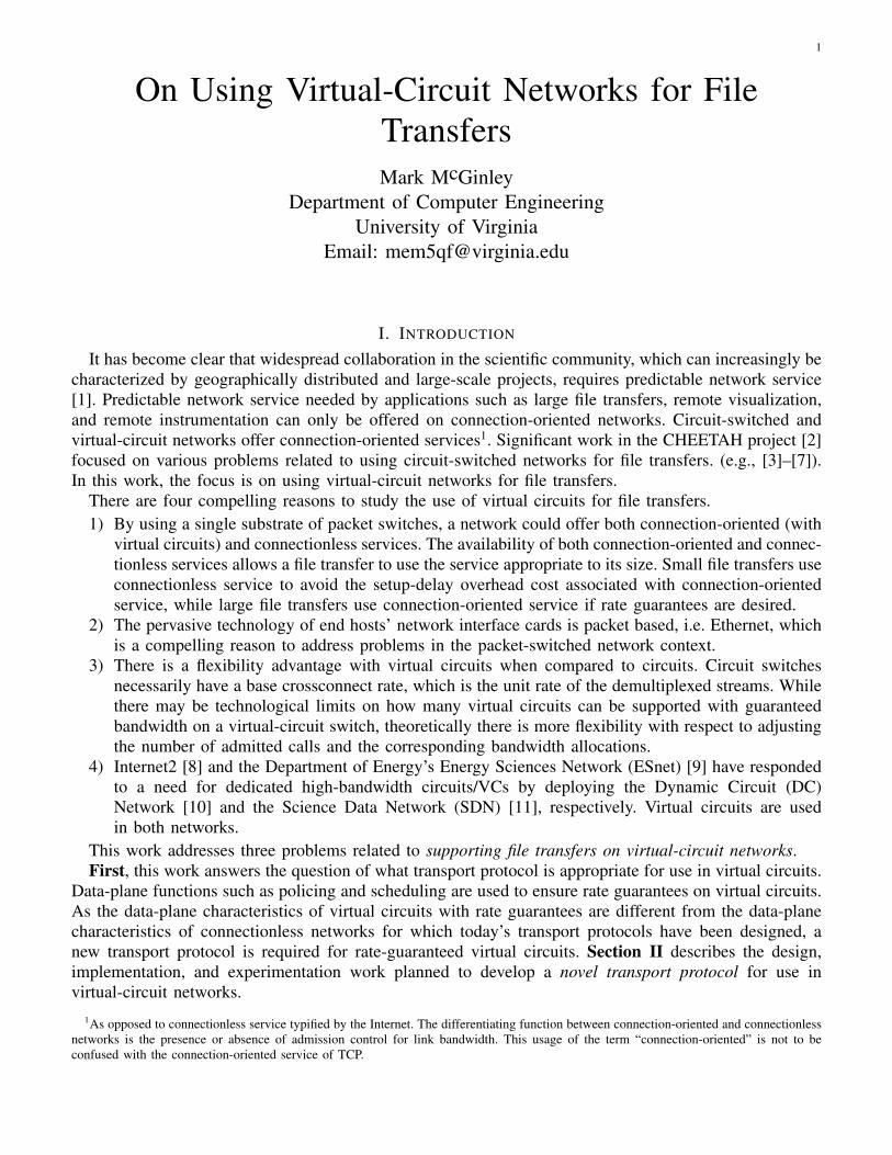
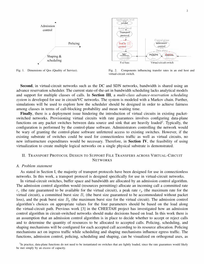
Fig. 1. Dimensions of Qos (Quality of Service). Fig. 2. Components influencing transfer rates in an end host andvirtual-circuit switch.
Second, in virtual-circuit networks such as the DC and SDN networks, bandwidth is shared using anadvance reservation scheduler. The current state-of-the-art in bandwidth scheduling lacks analytical modelsand support for multiple classes of calls. In Section III, a multi-class advance-reservation schedulingsystem is developed for use in circuit/VC networks. The system is modeled with a Markov chain. Further,simulations will be used to explore how the scheduler should be designed in order to achieve fairnessamong classes in terms of call-blocking probability and mean waiting time.
Finally, there is a deployment issue hindering the introduction of virtual circuits in existing packet-switched networks. Provisioning virtual circuits with rate guarantees involves configuring data-planefunctions on any packet switches between data source and sink that are heavily loaded2. Typically, theconfiguration is performed by the control-plane software. Administrators controlling the network wouldbe wary of granting the control-plane software unfettered access to existing switches. However, if theexisting substrate of switches could be used for connectionless traffic as well as virtual circuits, nonew infrastructure expenditures would be necessary. Therefore, in Section IV, the feasibility of usingvirtualization to create multiple logical networks on a single physical substrate is demonstrated.
II. TRANSPORT PROTOCOL DESIGN TO SUPPORT FILE TRANSFERS ACROSS VIRTUAL-CIRCUITNETWORKS
A. Problem statementAs stated in Section I, the majority of transport protocols have been designed for use in connectionless
networks. In this work, a transport protocol is designed specifically for use in virtual-circuit networks.In virtual-circuit switches, buffer space and bandwidth are allocated by an admission control algorithm.
The admission control algorithm would (resources permitting) allocate an incoming call a committed raterc (the rate guaranteed to be available for the virtual circuit), a peak rate rp (the maximum rate for thevirtual circuit), a committed burst size Bc (the burst size guaranteed to be accommodated without packetloss), and the peak burst size Bp (the maximum burst size for the virtual circuit). The admission controlalgorithm’s choices on appropriate values for the four parameters should be based on the load alongthe virtual-circuit path. Previous work [3] in the CHEETAH project has investigated how an admissioncontrol algorithm in circuit-switched networks should make decisions based on load. In this work there isan assumption that an admission control algorithm is in place to decide whether to accept or reject callsand to determine the quantity of resources to be allocated to accepted calls. Policing, scheduling, andshaping mechanisms will be configured for each accepted call according to its resource allocation. Policingmechanisms act on ingress traffic while scheduling and shaping mechanisms influence egress traffic. Thefunctions, admission control, policing, scheduling and shaping, can be visualized on orthogonal axes, as
2In practice, data-plane functions do not need to be instantiated on switches that are lightly loaded, since the rate guarantees would likelybe met simply by an excess of capacity.
3
shown in Fig. 1. Policing is necessary to provide virtual-circuits with rate guarantees by ensuring nocall’s traffic exceeds its resource allocation. Scheduling is configured such that traffic on a virtual circuitis serviced according to the rate determined by admission control. Traffic shaping can be used to smoothout the bursts so that the resulting trace adheres to desired characteristics set by the four parametersrc, rp, Bc, and Bp.
The conformance of the traffic entering the policer depends upon how traffic is sourced by the endhosts. On end hosts, there are multiple mechanisms that affect the characteristics of traffic, as shown inFig. 2. For example, consider the end host transmitting data. Since end hosts run multitasking general-purpose operating systems, commands to transmit data are inherently issued with a degree of burstinessby a process. There may be a traffic shaping mechanism in the end host to smooth out traffic. However,traffic shaping functions are not available in every operating system, and when they are available theyhave varying levels of accuracy due to end host timing issues. Without shaping, the bursty characteristicsof traffic from an end host could cause a significant portion of the traffic to be dropped at the first switch’spolicer. With the goal of reliable transport, it is the responsibility of the transport protocol to respond toloss, and if possible, prevent or limit the occurrence of loss. However, the appropriate actions a transportprotocol should take depend on the type of virtual circuit being used.
Virtual circuits can be of multiple types. A virtual circuit in which no traffic shaping occurs will behavedifferently from one in which switches have also been configured to perform traffic shaping. This workconsiders three “types” of virtual circuits that have fundamentally different properties as determined bythe presence and position of traffic shaping:
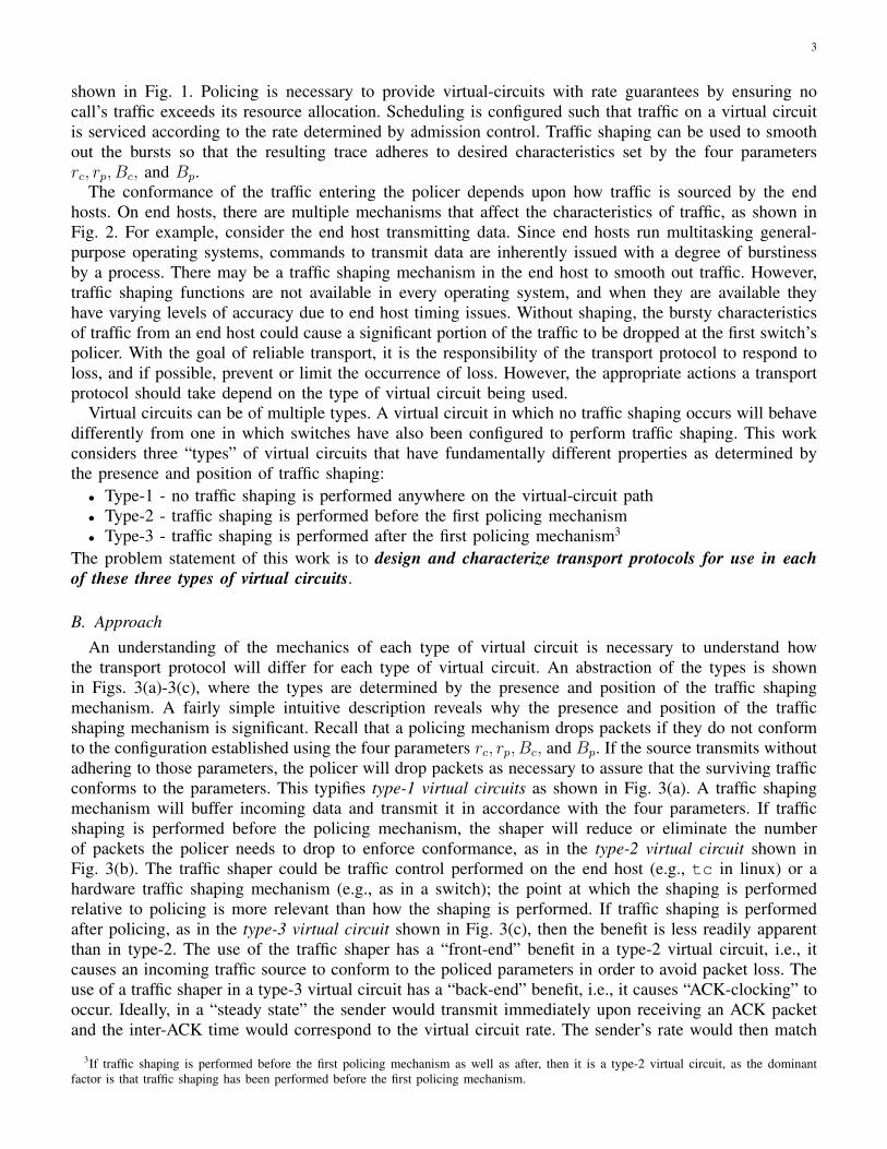
• Type-1 - no traffic shaping is performed anywhere on the virtual-circuit path• Type-2 - traffic shaping is performed before the first policing mechanism• Type-3 - traffic shaping is performed after the first policing mechanism3
The problem statement of this work is to design and characterize transport protocols for use in eachof these three types of virtual circuits.
B. ApproachAn understanding of the mechanics of each type of virtual circuit is necessary to understand how
the transport protocol will differ for each type of virtual circuit. An abstraction of the types is shownin Figs. 3(a)-3(c), where the types are determined by the presence and position of the traffic shapingmechanism. A fairly simple intuitive description reveals why the presence and position of the trafficshaping mechanism is significant. Recall that a policing mechanism drops packets if they do not conformto the configuration established using the four parameters rc, rp, Bc, and Bp. If the source transmits withoutadhering to those parameters, the policer will drop packets as necessary to assure that the surviving trafficconforms to the parameters. This typifies type-1 virtual circuits as shown in Fig. 3(a). A traffic shapingmechanism will buffer incoming data and transmit it in accordance with the four parameters. If trafficshaping is performed before the policing mechanism, the shaper will reduce or eliminate the numberof packets the policer needs to drop to enforce conformance, as in the type-2 virtual circuit shown inFig. 3(b). The traffic shaper could be traffic control performed on the end host (e.g., tc in linux) or ahardware traffic shaping mechanism (e.g., as in a switch); the point at which the shaping is performedrelative to policing is more relevant than how the shaping is performed. If traffic shaping is performedafter policing, as in the type-3 virtual circuit shown in Fig. 3(c), then the benefit is less readily apparentthan in type-2. The use of the traffic shaper has a “front-end” benefit in a type-2 virtual circuit, i.e., itcauses an incoming traffic source to conform to the policed parameters in order to avoid packet loss. Theuse of a traffic shaper in a type-3 virtual circuit has a “back-end” benefit, i.e., it causes “ACK-clocking” tooccur. Ideally, in a “steady state” the sender would transmit immediately upon receiving an ACK packetand the inter-ACK time would correspond to the virtual circuit rate. The sender’s rate would then match
3If traffic shaping is performed before the first policing mechanism as well as after, then it is a type-2 virtual circuit, as the dominantfactor is that traffic shaping has been performed before the first policing mechanism.
4
(a) Type-1: No traffic shaping per-formed.
(b) Type-2: Traffic shaping performed beforepolicing mechanism.
(c) Type-3: Traffic shaping performed after polic-ing mechanism.
Fig. 3. Types of virtual circuits.
the virtual circuit rate, due to ACK-clocking [12]. If the sender’s rate matches the virtual circuit rate,the policer would not need to drop packets and there would be no buildup of packets in the buffer atthe switch; ideally, only a single packet for each virtual circuit would in the switch at any instant. Theuse of traffic shaping anywhere along the virtual circuit path would encourage ACK-clocking. Relatingto current technology, the reason type-3 virtual circuits are used is that traffic control on end hosts isnot available in every operating system, and it is not always practical to add hardware to perform trafficshaping before the policer.
Now that the basic differences between the three types of virtual circuits have been identified, letus consider how we design transport protocols for each type. The answer is simplest for type-2 virtualcircuits. With shaping done before policing, the behavior of type-2 virtual circuits is quite similar to thatof circuits, and hence our previously designed CTCP protocol can be reused for type-2 virtual circuits.In CTCP, (i) a burst of size BDP is sent, and (ii) the congestion window is unchanged when loss occursunder the assumption that the “loss” is due to a link transmission error. For type-1 and type-3 virtualcircuits, a new transport protocol must be designed with two changes. First, instead of the entire BDPbeing immediately transmitted, there is an initial “ramp-up” phase to incrementally increase the congestionwindow. Second, the protocol should react to loss in a way appropriate for the virtual-circuit type. Thesechanges are necessary in order that the new transport protocol Virtual Circuit TCP (VCTCP) limitsthe bursts that the first policer experiences.
The central tenet in designing VCTCP is to limit the burst that the first switch with a policer inthe virtual circuit would experience at any point in a virtual circuit’s lifetime. We begin by discussingVCTCP’s configuration for type-2 virtual circuits. As we have just shown, CTCP is fully sufficient fora type-2 virtual circuit. However, there is a benefit in having a single transport protocol that can beconfigured to behave appropriately for any virtual-circuit type; therefore, we have designed VCTCP suchthat it can be configured to have identical operation to CTCP, for use in type-2 virtual circuits. This isachieved by initializing the congestion window to the BDP in packets, setting the increment to 0, andsetting the value to which the congestion window is reduced after a loss to the BDP in packets. Whenso configured, VCTCP will behave exactly like CTCP, and should be used for type-2 virtual circuits. Fortype-1 and type-3 virtual circuits, VCTCP should be configured to start with a ramp-up phase, and reactto loss in a way appropriate to the virtual-circuit type.
Ramp-up phase: In type-1 and type-3 virtual circuits, at the beginning of a transfer, before ACK-clocking has started, VCTCP must incrementally increase the congestion window to prevent a large burstfrom being produced. To accomplish this, we bound the burst by scaling up the congestion window. Theincrement will be a configurable parameter. For example, we could increase the congestion window byBc every RTT, causing the maximum per-RTT burst to be Bc. As this work investigates supporting largefile transfers, we consider the “ramping-up” phase during which the increments are occurring to be short-lived and a negligible part of the file transfers. The goal is to safely enter the ACK-clocking phase in acontrolled manner, rather than immediately maximizing throughput.
Reaction to loss: For type-1 virtual circuits, the reaction to packet loss should be to reduce thecongestion window significantly. The rational behind this significant reduction can be understood byconsidering what happens in the event of a packet loss. If a loss occurs, for every packet received afterthe expected lost packet, the receiver will send an acknowledgement to the sender indicating that it isexpecting the lost packet. When the sender receives three duplicate acknowledgements, it assumes the

5
packet was lost and retransmits the lost packet. When the retransmitted packet reaches the receiver, thereceiver responds with an acknowledgement that covers the lost packet as well as the packets subsequent tothe lost packet that have been buffered but not acknowledged. If this cumulative acknowledgement allowsthe sender to transmit a burst higher than the policer permits (which would be the common scenario), losswill occur again, and the pattern may repeat. With the frequent occurrence of loss in type-1 virtual circuits,the reaction to loss should be very conservative and reduce the congestion window by a significant amountafter packet loss. The probability of loss is higher in type-1 virtual circuits than in type-2 or type-3 becausein type-1 virtual circuits, useful ACK-clocking (that is, ACK-clocking that will ensure that the policer willnot drop packets) can only occur if a link on the path is fully loaded. A fully loaded link may cause onesource’s traffic to become interleaved with other sources’ traffic such that the resulting transmission ratefor that source’s traffic adheres to the virtual-circuit committed rate. This situation is unlikely to occurfor significant periods of time. Stable ACK-clocking, therefore, will rarely be achieved in the absence ofa traffic shaping mechanism. If packet loss is to be completely avoided, VCTCP would never allow moredata to be outstanding than the Bc. Thus there is a tradeoff to be experimentally explored; configuringVCTCP with more aggressive parameter values may lead to greater throughput but at the expense of morepacket loss. However, the response to loss in a type-3 virtual circuit can be a relatively small reaction. Weare relying on ACK-clocking to help the transmit rate adhere to the policing parameters. If a loss occurs ina type-3 virtual circuit, it is likely that only a small burst has occurred, and a corrective action that includesa small decrease in the congestion window is appropriate to help restore or preserve ACK-clocking. Justas with type-1 virtual circuits, the degree to which the congestion window is reduced for type-3 virtualcircuits in response to a loss is a configurable parameter that will be explored experimentally.
In summary, our approach is to use a transport protocol designed for each type of virtual circuit. Fortype-1 virtual circuits, we will use VCTCP configured to react with a large reduction of the congestionwindow in response to loss. For type-2 virtual circuits, we configure VCTCP to be identical to CTCP.For type-3 virtual circuits, we use VCTCP configured to have only a small reaction in response to packetloss.
C. Proposed workOur proposed work is to implement our approach (with the possibility of making “rapid-prototyping”
changes as needed) and evaluate the result for each type of virtual circuit. The implementation taskinvolves using kernel modules to dynamically insert our transport protocols (CTCP and VCTCP) intothe Linux kernel. We will evaluate each of the three components of our hypothesis using the appropriatevirtual-circuit type. End hosts tag traffic with the appropriate VLAN tag (IEEE 802.1Q [13]) to directtraffic onto the virtual circuit, and the policing and traffic shaping mechanisms in the virtual circuit pathare configured to identify and perform their functions based on the VLAN tag.
In our experiments, we will use BWdetail [14] (a tool that transmits data while recording values of thekernel’s TCP stack) on the virtual circuit to transfer large files. On the end hosts, we will use benchmarkingtools (bonnie++ [15] for hard drive load and interbench [16] for CPU load) to concurrently generate loadas well as measure system performance. Given end hosts’ multitasking behavior, we are interested in howeach protocol’s performance varies depending on the load at the end hosts.
Our experimental setups differ based on the type of virtual circuits created. In each setup, pairs of endhosts will communicate via virtual circuits of that type. Initially, each end host will participate in a filetransfer across a single virtual circuit, as we develop the protocol. We will then increase the number ofvirtual circuits between pairs of end hosts until each end host is participating in file transfers across 10virtual circuits. The virtual circuits will be created in a distributed manner between the hosts (as opposedto 10 virtual circuits between the same pair) to avoid synchronization effects.
Our evaluation will be performed according to the virtual-circuit type as follows.1) Type-1 virtual circuit - no traffic shaping is performed anywhere on the virtual-circuit path:
6
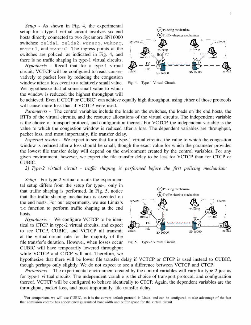
Fig. 4. Type-1 Virtual Circuit.
Setup - As shown in Fig. 4, the experimentalsetup for a type-1 virtual circuit involves six endhosts directly connected to two Sycamore SN16000switches: zelda1, zelda2, wuneng, wukong,mvstu1, and mvstu2. The ingress points at theswitches are policed, as indicated in Fig. 4, andthere is no traffic shaping in type-1 virtual circuits.
Hypothesis - Recall that for a type-1 virtualcircuit, VCTCP will be configured to react conser-vatively to packet loss by reducing the congestionwindow after a loss event to a relatively small value.We hypothesize that at some small value to whichthe window is reduced, the highest throughput willbe achieved. Even if CTCP or CUBIC4 can achieve equally high throughput, using either of those protocolswill cause more loss than if VCTCP were used.
Parameters - The control variables include the loads on the switches, the loads on the end hosts, theRTTs of the virtual circuits, and the resource allocations of the virtual circuits. The independent variableis the choice of transport protocol, and configuration thereof. For VCTCP, the independent variable is thevalue to which the congestion window is reduced after a loss. The dependent variables are throughput,packet loss, and most importantly, file transfer delay.
Expected results - We expect to see that for a type-1 virtual circuits, the value to which the congestionwindow is reduced after a loss should be small, though the exact value for which the parameter providesthe lowest file transfer delay will depend on the environment created by the control variables. For anygiven environment, however, we expect the file transfer delay to be less for VCTCP than for CTCP orCUBIC.
2) Type-2 virtual circuit - traffic shaping is performed before the first policing mechanism:
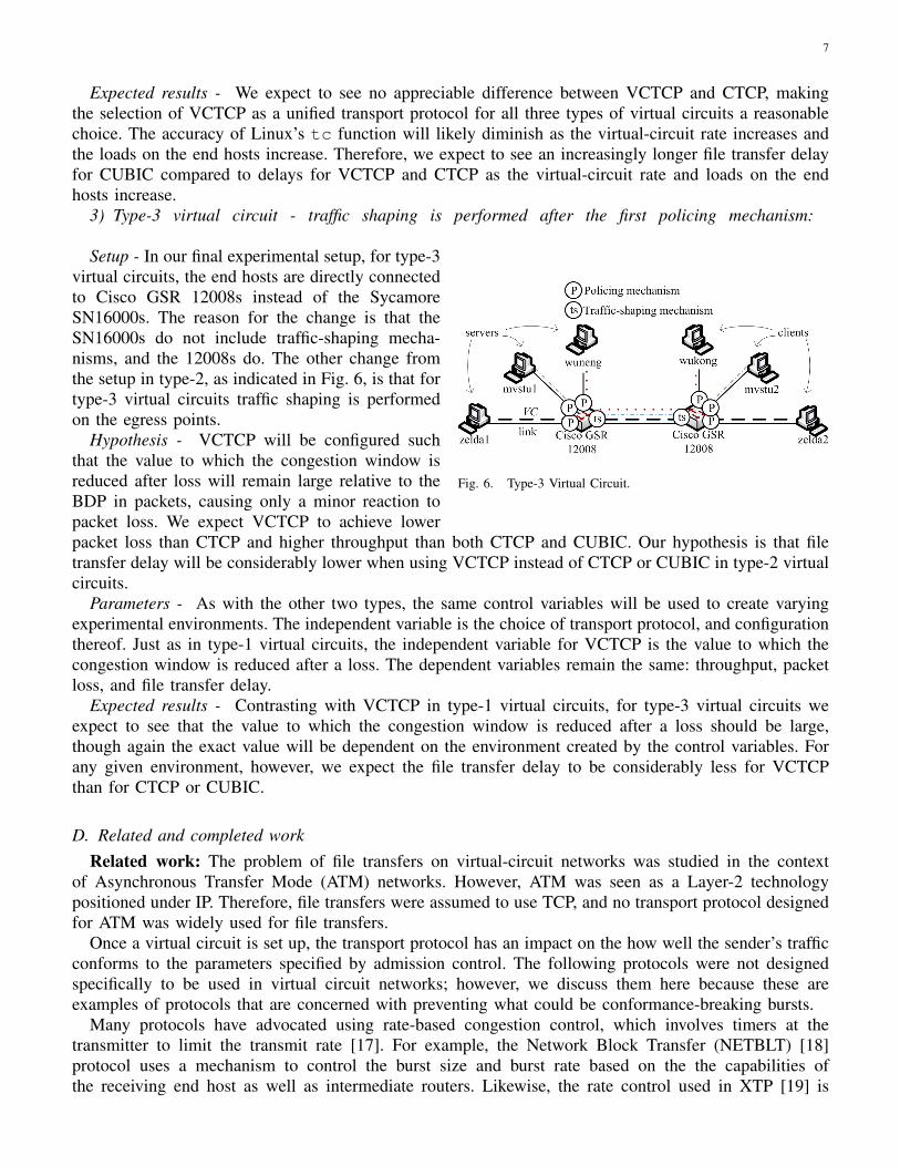
Fig. 5. Type-2 Virtual Circuit.
Setup - For type-2 virtual circuits the experimen-tal setup differs from the setup for type-1 only inthat traffic shaping is performed. In Fig. 5, noticethat the traffic-shaping mechanism is executed onthe end hosts. For our experiments, we use Linux’stc function to perform traffic shaping at the endhosts.
Hypothesis - We configure VCTCP to be iden-tical to CTCP in type-2 virtual circuits, and expectto see CTCP, CUBIC, and VCTCP all transmitat the virtual-circuit rate for the majority of thefile transfer’s duration. However, when losses occurCUBIC will have temporarily lowered throughputwhile VCTCP and CTCP will not. Therefore, wehypothesize that there will be lower file transfer delay if VCTCP or CTCP is used instead to CUBIC,though perhaps only slightly. We do not expect to see a difference between VCTCP and CTCP.
Parameters - The experimental environment created by the control variables will vary for type-2 just asfor type-1 virtual circuits. The independent variable is the choice of transport protocol, and configurationthereof. VCTCP will be configured to behave identically to CTCP. Again, the dependent variables are thethroughput, packet loss, and most importantly, file transfer delay.
4For comparison, we will use CUBIC, as it is the current default protocol is Linux, and can be configured to take advantage of the factthat admission control has apportioned guaranteed bandwidth and buffer space for the virtual circuit.
7
Expected results - We expect to see no appreciable difference between VCTCP and CTCP, makingthe selection of VCTCP as a unified transport protocol for all three types of virtual circuits a reasonablechoice. The accuracy of Linux’s tc function will likely diminish as the virtual-circuit rate increases andthe loads on the end hosts increase. Therefore, we expect to see an increasingly longer file transfer delayfor CUBIC compared to delays for VCTCP and CTCP as the virtual-circuit rate and loads on the endhosts increase.
3) Type-3 virtual circuit - traffic shaping is performed after the first policing mechanism:
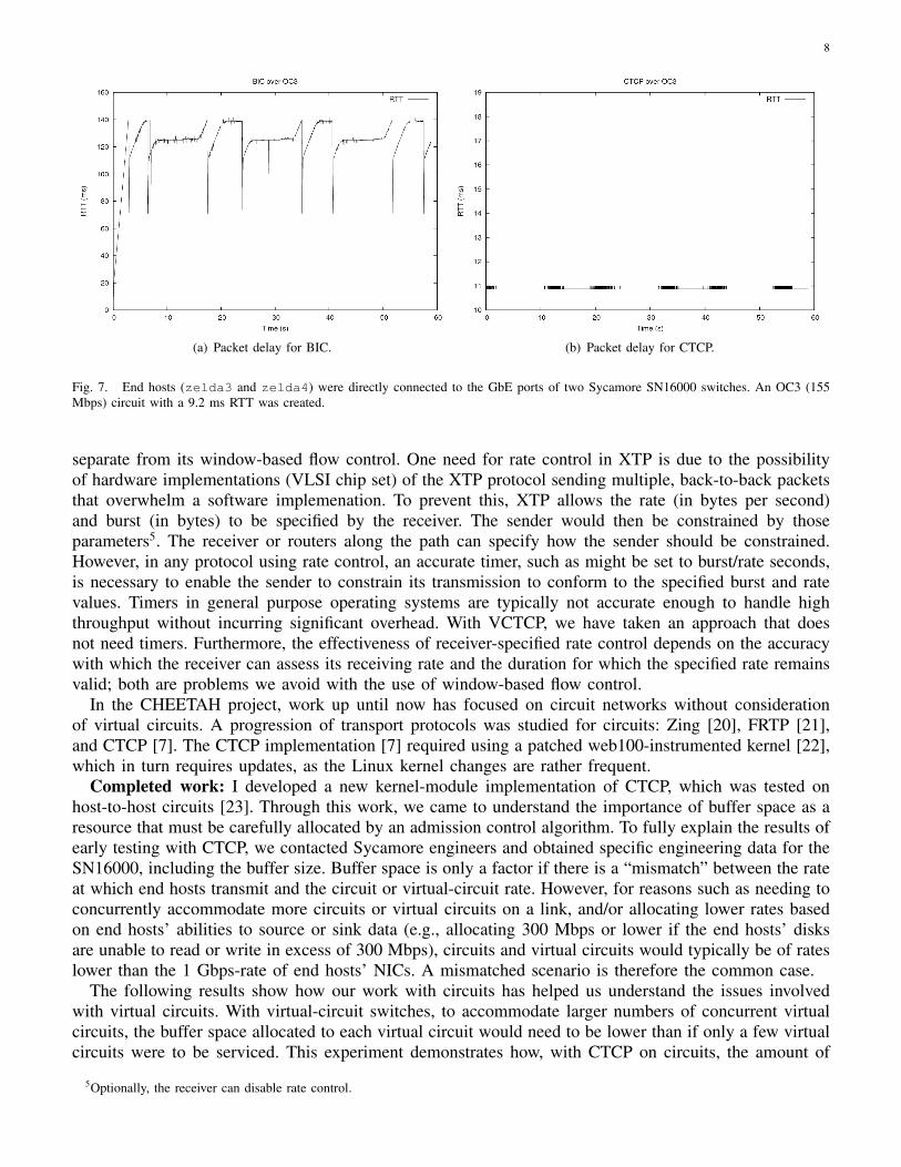
Fig. 6. Type-3 Virtual Circuit.
Setup - In our final experimental setup, for type-3virtual circuits, the end hosts are directly connectedto Cisco GSR 12008s instead of the SycamoreSN16000s. The reason for the change is that theSN16000s do not include traffic-shaping mecha-nisms, and the 12008s do. The other change fromthe setup in type-2, as indicated in Fig. 6, is that fortype-3 virtual circuits traffic shaping is performedon the egress points.
Hypothesis - VCTCP will be configured suchthat the value to which the congestion window isreduced after loss will remain large relative to theBDP in packets, causing only a minor reaction topacket loss. We expect VCTCP to achieve lowerpacket loss than CTCP and higher throughput than both CTCP and CUBIC. Our hypothesis is that filetransfer delay will be considerably lower when using VCTCP instead of CTCP or CUBIC in type-2 virtualcircuits.
Parameters - As with the other two types, the same control variables will be used to create varyingexperimental environments. The independent variable is the choice of transport protocol, and configurationthereof. Just as in type-1 virtual circuits, the independent variable for VCTCP is the value to which thecongestion window is reduced after a loss. The dependent variables remain the same: throughput, packetloss, and file transfer delay.
Expected results - Contrasting with VCTCP in type-1 virtual circuits, for type-3 virtual circuits weexpect to see that the value to which the congestion window is reduced after a loss should be large,though again the exact value will be dependent on the environment created by the control variables. Forany given environment, however, we expect the file transfer delay to be considerably less for VCTCPthan for CTCP or CUBIC.
D. Related and completed workRelated work: The problem of file transfers on virtual-circuit networks was studied in the context
of Asynchronous Transfer Mode (ATM) networks. However, ATM was seen as a Layer-2 technologypositioned under IP. Therefore, file transfers were assumed to use TCP, and no transport protocol designedfor ATM was widely used for file transfers.
Once a virtual circuit is set up, the transport protocol has an impact on the how well the sender’s trafficconforms to the parameters specified by admission control. The following protocols were not designedspecifically to be used in virtual circuit networks; however, we discuss them here because these areexamples of protocols that are concerned with preventing what could be conformance-breaking bursts.
Many protocols have advocated using rate-based congestion control, which involves timers at thetransmitter to limit the transmit rate [17]. For example, the Network Block Transfer (NETBLT) [18]protocol uses a mechanism to control the burst size and burst rate based on the the capabilities ofthe receiving end host as well as intermediate routers. Likewise, the rate control used in XTP [19] is
8
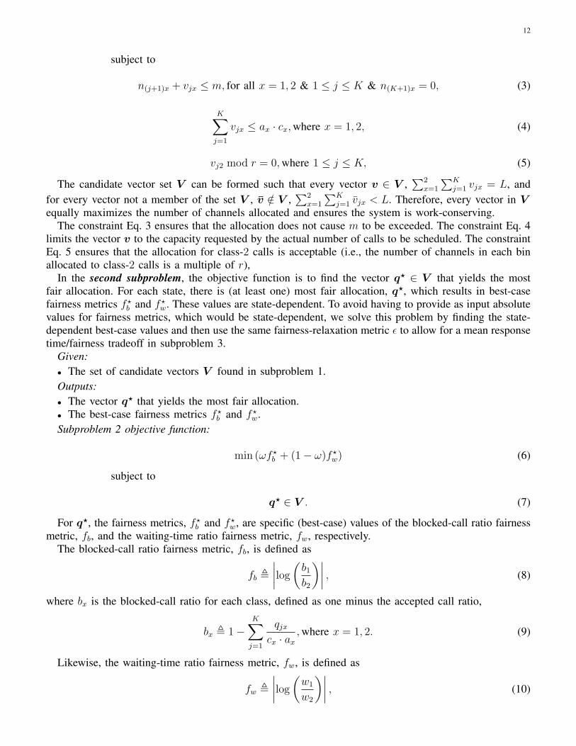
(a) Packet delay for BIC. (b) Packet delay for CTCP.
Fig. 7. End hosts (zelda3 and zelda4) were directly connected to the GbE ports of two Sycamore SN16000 switches. An OC3 (155Mbps) circuit with a 9.2 ms RTT was created.
separate from its window-based flow control. One need for rate control in XTP is due to the possibilityof hardware implementations (VLSI chip set) of the XTP protocol sending multiple, back-to-back packetsthat overwhelm a software implemenation. To prevent this, XTP allows the rate (in bytes per second)and burst (in bytes) to be specified by the receiver. The sender would then be constrained by thoseparameters5. The receiver or routers along the path can specify how the sender should be constrained.However, in any protocol using rate control, an accurate timer, such as might be set to burst/rate seconds,is necessary to enable the sender to constrain its transmission to conform to the specified burst and ratevalues. Timers in general purpose operating systems are typically not accurate enough to handle highthroughput without incurring significant overhead. With VCTCP, we have taken an approach that doesnot need timers. Furthermore, the effectiveness of receiver-specified rate control depends on the accuracywith which the receiver can assess its receiving rate and the duration for which the specified rate remainsvalid; both are problems we avoid with the use of window-based flow control.
In the CHEETAH project, work up until now has focused on circuit networks without considerationof virtual circuits. A progression of transport protocols was studied for circuits: Zing [20], FRTP [21],and CTCP [7]. The CTCP implementation [7] required using a patched web100-instrumented kernel [22],which in turn requires updates, as the Linux kernel changes are rather frequent.
Completed work: I developed a new kernel-module implementation of CTCP, which was tested onhost-to-host circuits [23]. Through this work, we came to understand the importance of buffer space as aresource that must be carefully allocated by an admission control algorithm. To fully explain the results ofearly testing with CTCP, we contacted Sycamore engineers and obtained specific engineering data for theSN16000, including the buffer size. Buffer space is only a factor if there is a “mismatch” between the rateat which end hosts transmit and the circuit or virtual-circuit rate. However, for reasons such as needing toconcurrently accommodate more circuits or virtual circuits on a link, and/or allocating lower rates basedon end hosts’ abilities to source or sink data (e.g., allocating 300 Mbps or lower if the end hosts’ disksare unable to read or write in excess of 300 Mbps), circuits and virtual circuits would typically be of rateslower than the 1 Gbps-rate of end hosts’ NICs. A mismatched scenario is therefore the common case.
The following results show how our work with circuits has helped us understand the issues involvedwith virtual circuits. With virtual-circuit switches, to accommodate larger numbers of concurrent virtualcircuits, the buffer space allocated to each virtual circuit would need to be lower than if only a few virtualcircuits were to be serviced. This experiment demonstrates how, with CTCP on circuits, the amount of
5Optionally, the receiver can disable rate control.

9
buffer space in the switch used is low because ACK-clocking ensures that the sending rate matches therate of the circuit. We can see that the buffer space used is low by comparing the RTT for CTCP with theRTT when BIC [24] is used and allowing BIC to increase the number of outstanding packets. A largerRTT during the data transfer is a result of packets building up in the switch’s buffer. The native RTT inthis setup was 9.2 ms. We can see in Fig. 7 how the RTT for BIC grows to a maximum of 140 ms (shownin Fig. 7(a)), whereas with CTCP there is a steady RTT of around 11 ms (shown in Fig. 7(b)). Theseresults helped us understand the demand on the switch’s buffer, a primary consideration in virtual-circuitswitches.
III. FAIRNESS IN MULTI-CLASS BOOK-AHEAD SCHEDULING
A. Problem definitionThe motivation for this work is to extend the BA-First algorithm [5] to accommodate multiple classes.
The original work included an analytical model for a single-class, single-link book-ahead (BA) bandwidthscheduler for session-type requests. BA-First is a single-class algorithm in that it discretizes the capacity Cof a link into m equal channels with capacity C/m, and assumes that each request is for one channel andone unit of time τ , referred to as a timeslot. The system maintains a reservation window of size K, whichtracks the number of channels reserved for calls in each time interval, for K future time intervals. Thereservation capacity of the system is mK timeslots. BA-First fulfills a request with the earliest availabletimeslot, or rejects the request if a channel is unavailable in the whole K-timeslot advance reservationwindow. As not all sessions require identical bandwidth, the original BA-First algorithm needs to bemodified to handle multiple types of requests. For example, a remote visualization session may require300 Mbps to display large amounts of data while a distance-learning session may only require 100 Mbps.Hence we design a BA scheme to support multiple classes.
An important consideration for a scheduling system with multiple classes is fairness. The objective ofthe scheduling algorithm is to minimize mean response time while meeting a tunable fairness constraintin terms of the blocked-call ratio and waiting-time ratio for each class, and maximizing the number ofallocated channels across all time intervals.
B. ApproachLink capacity C is discretized into m channels with equal bandwidth C/m. To accommodate multiple
classes of calls, cx denotes the number of channels requested by a class-x call. To gain a basic under-standing of the impact of multiple classes, we limit our model to a 2-class system (i.e., x = {1, 2}). Thecall-arrival process for each class-x is assumed to be Poisson with rate λx, and and we define β = λ2
λ1.
The proportion r of the number of channels requested by the classes is given by r = c2c1
, normalizingc1 to equal one channel, c2 = r. Time is discretized into equal-length intervals of duration τ , as shownin Fig. 8. Each time interval can be thought of as a “bin”, such that there are K bins in the reservationwindow, each with capacity m. Though requests can arrive at any instant, service for calls begins andends only at interval boundaries. Therefore, even if there are available channels to immediately servicea just-arrived request, the earliest time the request will be scheduled to start will be at the next intervalboundary.
At each time interval boundary, the scheduling mechanism is invoked to schedule the calls that havearrived during the just-past interval. The scheduling algorithm is responsible for achieving fairness betweenthe two classes in terms of call-blocking probability and mean waiting time. To accomplish this, anoptimization function determines how the unassigned calls should be scheduled.
1) Non-homogeneous Continuous-Time Markov Chain model: The system state is described by a 2+2 ·K-element vector, (n11, n12, n21, n22, . . . , nK1, nK2, a1, a2), where nix is the number of channels occupied,i being the index for the bin, and x being the index for the class. The elements a1 and a2 are the numbersof unassigned class-1 and class-2 calls.

10
Fig. 8. An illustration of the BA-First scheduler for multiple classes.
The state space S is defined as
S ,
n = (n11, n12, n21, n22, . . . , nK1, nK2, a1, a2) :∀j, 1 ≤ j ≤ K,nj1 + nj2r ≤ m and a1, a2 ∈ Z+
and 1 ≤ j ≤ K,nj2 mod r = 0
,
where Z+ is the set of all non-negative integers.Given the difference in how the system transitions states within an interval and how it transitions states
at interval boundaries, the system can be modeled as a non-homogeneous continuous-time Markov chain(CTMC). However, it contains an embedded time-homogeneous discrete-time Markov chain (DTMC) ifonly the time interval boundaries are considered.
2) Discrete-time Markov Chain model: The discrete time instants in the DTMC are the instants justbefore the scheduling mechanism is executed.
The transition probability from an origin state n to a destination state n′, denoted p(n,n′
), is
p(n,n′
)=
{PA1(a
′1) · PA2(a
′2) if n′jx = n(j+1)x + qjx,where x = 1, 2 & 1 ≤ j ≤ K & n(K+1)x = 0,
0 otherwise,(1)
where PAx(a) is the Probability Mass Function (PMF) of Ax, a Poisson random variable with parameterλxτ , representing the number of class-x call arrivals within a time interval, and qjx are elements of qnas determined by the optimization problem, i.e., qn = OPT (n). The optimization function OPT (n)takes the origin state n and outputs a vector qn , q11, q12, q21, q22, . . . , qK1, qK2, n∈ S, where qix is thenumber of additional channels reserved in bin i for a class-x call.
3) Optimization problem: The optimization function, OPT (n), determines the division of free spacein all bins to the arrived but unscheduled calls with the objective of minimizing the mean response timewhile meeting a tunable fairness constraint in terms of the blocked-call ratio and waiting time for eachclass, and maximizing the number of allocated channels across all bins.

11
The optimization determines the allocation vector qn based on the origin state, n = (n11, . . . , nK2, a1, a2).For simplicity, n is omitted from the notation, i.e.qn is denoted as q with n being implicit. This omissionapplies to the following variables and output metrics as well, all of which are state-dependent:
• q?n as q?, the most fair allocation vector• Rn as R, the mean response time for admitted calls• bn,x as bx, the blocked-call ratio for each class• fn,b as fb, the blocked-call ratio fairness metric• wn,x as wx, the waiting-time ratio for each class• fn,w as fw, the waiting-time ratio fairness metric• f ?n,b as f ?b , the specific value of the blocked-call ratio fairness metric given by q?
• f ?n,w as f ?w, the specific value of the waiting-time ratio fairness metric given by q?
• ψn as ψ, an index variable• V n as V , the set of candidate vectors• Ln as L, the maximum number of channels that can be scheduled.
The omission does not apply to the system variables, which are state-independent:• C, the link capacity• m, the number of channels with equal bandwidth C
m• cx, the number of channels request by a class-x call• r, with r = c2
c1(class-1 call bandwidth is defined as a single channel)
• K, the reservation window.Further, there are additional system variables used only in the optimization, which are also state-independent:
• ε, a fairness-relaxation variable to tradeoff fairness and mean response time for admitted calls• ω, the weight used to dictate the value of each fairness metric (e.g., ω = 0.5 would value the
blocked-call and waiting-time ratio fairness metrics equally).The overall optimization problem for a given origin state, OPT (n), is divided into three optimization
subproblems.• Subproblem 1 finds the allocations that maximize the number of allocated channels across all bins.• Subproblem 2 finds the most fair allocation from among those found in subproblem 1.• Subproblem 3 finds the allocation with the minimum mean response time that achieves fairness within
a range specified by ε of the fairness of the most fair allocation, as determined in subproblem 2.In the first subproblem, the optimization finds the maximum number of channels that can be allocated
given the bin occupancy of state n. The purpose of this step is to minimize blocked-call ratios in a waythat does not give preference to class-1 calls. That is, if we simply tried to minimize the number ofblocked calls, we would schedule as many class-1 calls as possible, and then schedule as many class-2calls as could fit, treating class-2 unfairly. Instead, we find all possible ways to schedule the arrived callsthat would equally use the available capacity given the bin occupancy of state n. The objective functionof the first subproblem is to find L, the maximum amount of channels that can be allocated given the binoccupancy of state n (limited by the number of arrived but unscheduled calls in n), from which the setV is determined.
Given:• The state n and the system variables listed above.Output:• The set of candidate vectors V defined as V , {vjx,where x = 1, 2 & 1 ≤ j ≤ K}Subproblem 1 objective function:
maxL ,2∑
x=1
K∑j=1
vjx (2)
12
subject to
n(j+1)x + vjx ≤ m, for all x = 1, 2 & 1 ≤ j ≤ K & n(K+1)x = 0, (3)
K∑j=1
vjx ≤ ax · cx,where x = 1, 2, (4)
vj2 mod r = 0,where 1 ≤ j ≤ K, (5)
The candidate vector set V can be formed such that every vector v ∈ V ,∑2
x=1
∑Kj=1 vjx = L, and
for every vector not a member of the set V , v /∈ V ,∑2
x=1
∑Kj=1 vjx < L. Therefore, every vector in V
equally maximizes the number of channels allocated and ensures the system is work-conserving.The constraint Eq. 3 ensures that the allocation does not cause m to be exceeded. The constraint Eq. 4
limits the vector v to the capacity requested by the actual number of calls to be scheduled. The constraintEq. 5 ensures that the allocation for class-2 calls is acceptable (i.e., the number of channels in each binallocated to class-2 calls is a multiple of r),
In the second subproblem, the objective function is to find the vector q? ∈ V that yields the mostfair allocation. For each state, there is (at least one) most fair allocation, q?, which results in best-casefairness metrics f ?b and f ?w. These values are state-dependent. To avoid having to provide as input absolutevalues for fairness metrics, which would be state-dependent, we solve this problem by finding the state-dependent best-case values and then use the same fairness-relaxation metric ε to allow for a mean responsetime/fairness tradeoff in subproblem 3.
Given:• The set of candidate vectors V found in subproblem 1.Outputs:• The vector q? that yields the most fair allocation.• The best-case fairness metrics f ?b and f ?w.Subproblem 2 objective function:
min (ωf?b + (1− ω)f ?w) (6)
subject to
q? ∈ V . (7)
For q?, the fairness metrics, f ?b and f ?w, are specific (best-case) values of the blocked-call ratio fairnessmetric, fb, and the waiting-time ratio fairness metric, fw, respectively.
The blocked-call ratio fairness metric, fb, is defined as
fb ,
∣∣∣∣log
(b1b2
)∣∣∣∣ , (8)
where bx is the blocked-call ratio for each class, defined as one minus the accepted call ratio,
bx , 1−K∑j=1
qjxcx · ax
,where x = 1, 2. (9)
Likewise, the waiting-time ratio fairness metric, fw, is defined as
fw ,
∣∣∣∣log
(w1
w2
)∣∣∣∣ , (10)

13
where wx is given by
wx ,ψ−1∑j=1
(j − 1) · qjxcx,where x = 1, 2, (11)
in which ψ is the earliest bin to which no calls of one of the classes will be scheduled. We define ψ as
ψ , min j, 1 ≤ j ≤ K & x = 1, 2 for which qjx > 0. (12)
The purpose of ψ is to make the waiting-time ratio fairness metric as fair as it can be, given there aredifferences in the number of calls of each class. For example, if only a single class-2 call arrived, butenough class-1 calls arrived to fill several bins, it would make the system look very unfair in favor ofclass-2 if the waiting time for the allocation across all bins were considered. By using ψ to limit thenumber of bins considered in evaluating waiting-time ratio fairness to just those bins up to and includingthe last bin to which calls of both classes were admitted, we obtain a true measure of waiting-time ratiofairness.
In the third optimization subproblem, the objection function is to chose the vector q ∈ V that minimizesthe mean response time R for admitted calls, but will result in fairness metrics constrained by a relaxed-fairness range determined by the fairness-relaxation metric. Mean response time is the average time untila call receives service (the time between call arrival and the time interval boundary when the call isscheduled is ignored), defined as
R ,
∑Kj=1(j − 1) · qj1 +
∑Kj=1(j − 1) · qj2
c2∑Kj=1 qj1 +
∑Kj=1
qj2c2
. (13)
Given:• The set of candidate vectors V found in subproblem 1.• The fairness metrics f ?b and f ?w found in subproblem 2.Outputs:• The vector q that yields the minimum mean response time.• The fairness metrics fb and fw, and minimum mean response time R.Subproblem 3 objective function:
minR (14)
subject toωf?b + (1− ω)f ?w ≤ ωfb + (1− ω)fw ≤ (ωf?b + (1− ω)f ?w) + ε (15)
The constraint Eq. 15 allows for a tradeoff between relaxing fairness and minimizing the mean responsetime by varying the fairness scaling factor, ε. For q?, the most fair allocation, the mean response timewould be R?. The scaling factor allows a less fair solution to be found that would result in fairness metricsfb and fw within the range given in Eq. 15, for which there might be an allocation that yields R < R?.By varying ε within the range 0 ≤ ε < ∞, a tradeoff between fairness and mean response time can beexplored. For ε→ 0, the allocation will be more fair at the possible expense of a longer mean responsetime, while for ε→∞, the shortest mean response time may be experienced but with decreasing concernfor fairness.
In summary, the output of the overall optimization is the vector q , q11, q12, q21, q22, . . . , qK1, qK2
detailing the allocation of channels to new calls, the fairness metrics and mean response time of the mostfair allocation, f ?b , f ?w, and R?, and the fairness metrics and mean response time of the relaxed-fairnessoptimization, fb, fw, and R.
For example, in Fig. 9, (a) through (j) denote vectors in set V , which are determined by subproblem1. The vector (a) denotes the vector which is found in subproblem 2 to be the most fair allocation,with fairness f ?b and f ?w, and mean response time R?. Therefore, q? ≡ (a) in Fig. 9. In subproblem

14
Fig. 9. Optimization example; MRT: Mean Response Time.
3, the relaxed-fairness constraint has a range given by Eq. 15, which allows vectors (b) through (e) tobe considered. Minimizing for R as per Eq. 14, the optimization determines that the vector (d) has theminimum R. Therefore, q ≡ (d) in Fig. 9.
C. Proposed workSetup - Our proposed work includes three tasks: (i) solving the optimization problem OPT (n), (ii)
solving the DTMC, and (iii) running simulations. To solve the optimization, we will be using customcode to find the solution set for every state in a system defined by parameters m, K, and r. The DTMC,which will be solved using Matlab, and the simulations, which will be performed using custom code,will specify ε and ω to obtain results for a given system and query the optimization solution set to findOPT (n).
For systems with a “small-enough” state space, we will use Matlab to solve the DTMC. The state spacewill be a result of the optimization for given system parameters m, K, and r, so we can not quantifythe state space before the optimization is performed. In addition to using expert intuition to validate themodel and simulations, a comparison of the results of solving the DTMC and performing simulationsfor systems with small-enough state spaces will serve as a validation to both. Due to the memory- andcomputation-intensive nature of each of the tasks, we will use the ITC Linux cluster Dogwood or Elder.For systems with state spaces beyond those able to be solved with Matlab, we will obtain results usingonly simulations.
Hypothesis - We hypothesize that there is an inverse relationship between the ratio(rm
to K)
and εsuch that we can use either K or ε as “knobs” in the mean response time/fairness tradeoff.
Parameters - We will perform sensitivity analysis on each of the following parameters. We will varyK with a range of 4 to 10, m ranging from 5 to 20, and r ranging from 2 to 4. We will vary the λ valuessignificantly, representing high load from both classes, low load from both classes, and a mix of highload from one and low load from the other, giving us a range for β = λ2
λ1from .1 to 10. We will vary the
fairness weight ω from 0 to 1, and ε from 0 to a value determined through experimentation, which wouldallow any allocation to be considered.
Expected results - We expect to see that for ω → 0 or ω → 1, the system will either be very fair interms of one metric or the other, but not both. When ω ≈ .5, the system should be fair in terms of bothfairness metrics. Furthermore, we will plot the influence of the ratio of r
mto K on fairness, expecting
to see decreasing fairness experienced as the ratio increases. A larger ε will allow a low mean responsetime value to be maintained as the ratio of r
mto K increases, but at a fairness cost.
D. Related workThere has been a significant amount of theoretical work on advance reservation scheduling schemes,
[4], [25]–[75], as well as [5] from which this work extends. Our problem definition is unique in that we

15
are concerned with minimizing mean response time while considering fairness experienced by calls ofeach class in terms of call-blocking probability and waiting time in a multi-class, centralized scheduler forsession-type requests on a single-link. In most work, either one fairness metric or the other is considered.For example, in routing and wavelength assignment (RWA) work, the fairness metric is primarily call-blocking probability. In multiprocessor/job scheduling, the primary metric is typically the total time tocomplete a set of jobs (the “makespan”), and, sometimes, the waiting time experienced by jobs. However,since increasing the probability of blocking lowers the waiting time and makespan, and vice versa, thiswork pursues a book-ahead scheduler that considers both the blocking probability and waiting time, inaddition to the objective of minimizing the mean response time.
IV. VIRTUALIZING AN ETHERNET SWITCH
This work has been published [76] and presented at ICCCN 2008, and was nominated for the BestPaper Award.
A. Motivation and problem definitionAs noted in Section I, virtualization is proposed to leverage the advantage of offering connectionless and
connection-oriented service on a single substrate of packet switches. Two logical networks can be createdwith virtualized switches/routers, each of which has its own data-plane, control-plane, management-plane,and administrative-access partitions. One logical network can be used to offer connectionless service whilethe other offers connection-oriented service.
Virtualization is increasingly a focus in research and commercial sectors. For example, virtualization isa central concept in the NSF initiative to create a Global Environment for Network Innovations (GENI)[77]. As the GENI testbed is expected to have both host systems and network switches/routers (amongother entities), techniques are needed for virtualizing both hosts6 and switches/routers.
Existing solutions to virtualize switches/routers include: (i) software-based switches/routers created us-ing off-the-shelf servers, as implemented in the Virtual Network Infrastructure (VINI) project [82], and (ii)a hardware-based high-speed router/switch with Advanced Telecommunications Computing Architecture(ATCA) components and network processors as proposed in [83]. These fall at opposite ends of theflexibility/performance spectrum.
The switch/router virtualization solution in this work lies between these two extremes. It is basedon using off-the-shelf switches/routers and poses only one requirement on these switches, i.e., thatthe switch/router has built-in capabilities to support isolated slivers (bandwidth partitions) on its data-plane interfaces. Ideally, to create multiple logical switches from one physical switch, in addition tosupport for separable slivers on the data-plane, the switch should have built-in capabilities to supportmultiple, separable (a) control-plane instances, e.g., routing protocol and signaling protocol processes,(b) management-plane instances, e.g., Simple Network Management Protocol (SNMP) agents with par-titioned MIBs, and (c) Command-Line Interface (CLI) processing instances. In this proposed solutionfor switch/router virtualization, software external to the switch is used to partition the control plane,management plane, and CLI administrative-access, thus requiring built-in support for only data-planepartitioning.
B. Related workIn addition to the VINI and ATCA virtualization research efforts cited in Section IV-A, there is
growing interest in the commercial sector among equipment vendors to support built-in capabilities forswitch/router virtualization on all four levels (data, control, and management planes, and administrative
6The concept of virtualizing a computer host to create virtual machines has been widely implemented. There are several techniques forvirtualizing hosts in both commercial and research-and-education (R&E) communities such as VMware [78], Virtual Server [79], Xen [80],PlanetLab [81], etc.

16
(a) Virtualizing to create two logical switches: one for connec-tionless service, the other for connection-oriented service.
(b) Virtualizing in testbed networks such as GENI.
Fig. 10. Virtualization architecture for two scenarios.
access). New products are being created to virtualize both data-center switches [84] as well as high-end service-provider routers [85], [86]. For example, various departments of an organization can sharethe computers and switches in an enterprise data center. However, acquiring the new products wouldmean upgrading infrastructure, a costly proposition. In this work, the focus is on virtualizing existinginfrastructure without the need for new equipment purchases, as a large portion of deployed equipmentcan readily be virtualized using external software as described in this work.
C. Approach for virtualizationIn this section, an approach for virtualizing an off-the-shelf switch/router that has built-in support for
sliver isolation on its data-plane interfaces is described. Fig. 10 shows the virtualization architecture fortwo distinct scenarios. The focus in this work is on virtualizing a single switch, therefore, Fig. 10 showsjust a single switch and associated software.
In our virtualization architecture, we use the following terminology:• sliver is defined as a bandwidth partition on a port with a set of associated multiplexing/demultiplexing
identifiers, e.g. VLAN identifiers.• slice is used to represent a logical switch, which consists of a set of slivers on a specific set of ports
of the physical switch. This definition of the word “slice” is for a single switch, though this termhas been used in the GENI community to represent a set of resources across a whole network (i.e.,multiple switches).
• entity represents both a human administrator of a logical switch (slice) as well as software modulesimplemented by the slice owner to interface with the slice scheduler and Slice AdministrationController (SAC) of Fig. 10(b), as these software modules could offer both graphic and programmaticinterfaces.
In Fig. 10(a), we show how the virtualization architecture creates two logical switches, one of whichcould be used as part of a network offering connectionless service, and the other used to offer connection-oriented (CO) service. The administrator defines the slice used for connection-oriented service in the con-figuration database. The external connection-oriented control-plane software would control the connection-oriented logical switch by issuing commands through the SAC. There is no slice scheduler in thevirtualization architecture in this scenario because both services need to be available at all times.
The virtualization architecture for the research scenario such as GENI is shown in Fig. 10(b). Asstated in Section IV-A, multiple control-plane instances and management-plane instances are run outsidethe switches to provide corresponding functionality to the logical switches. Researchers access the slicescheduler to request reservations for switch slices for a fixed duration of time. The slice scheduler maintainsreservations for discrete time periods (e.g., hourly basis). The slice scheduler translates a slice request intoa set of required slivers and checks whether the request can be accepted based on resource availability in

17
TABLE I
CONFIGURATION DATABASE FOR ONE TIME INTERVAL
Class-mode VLAN-modeEntity Link1 Link3 Link2 Link4 P V
1 r11, b
11 r1
3, b13 r1
2, b12 r1
4, b14 P1 V1
2 r21, b
21 r2
3, b23 r2
2, b22 r2
4, b24 P2 V2
the requested time period. Sliver allocations for accepted reservations are written into the configurationdatabase shown in Fig. 10(b). The control-plane and management-plane instances issue commands via theSAC, which checks the configuration database to ensure the entity has appropriate permission.
D. Completed workIn this work, we designed the slice scheduler, designed and implemented the SAC, and characterized
the performance of our implementation. Our work was performed on the HOPI network, which consistedof Force10 E600 nodes deployed in five cities: Washington, New York, Chicago, Seattle, and Los Angeles.The Force10 E600 does meet this approach’s requirement of built-in support for sliver isolation on itsdata-plane interfaces. We virtualized the E600 to create multiple logical Ethernet switches out of a singlephysical switch.
The built-in support for sliver isolation on data-plane interfaces is met by Ethernet switches thatimplement the IEEE 802.1Q standard, which supports multiplexing based on 12-bit Virtual LAN identifiers(IDs) or the 3-bit priority field, and include appropriate policing and scheduling mechanisms. We use theterm “class” instead of priority when referring to the latter because in the virtualization application allslivers are treated equally. Virtual circuits are created, as described in Section II-A, through a combinationof policing, scheduling, and admission control. In order to virtualize the data plane of the switch, admissioncontrol, in the form of the slice scheduler, tracks aggregate port bandwidth when granting slice reservations,but the act of instantiating policing and scheduling mechanisms is left to the entity. We now describethe design of the slice scheduler, which is responsible for admission control, followed by the design andimplementation of the SAC, which is responsible for enforcing that the instantiation of slices by entitiesadheres to the bounds given by the slice scheduler.
1) Design of the slice scheduler: The slice scheduler must be designed to perform admission controlusing a book-ahead algorithm of the type described in Section III. The slice scheduler is responsible fordetermining the slice allocations. A slice allocation for a given time interval is represented as follows:(R,B,P,V), where (R = rel , 1 ≤ l ≤ L, e ε E) is the set of requested rates on all the links of the switch, Eis the set of entities, and L is the number of links (interfaces) on the switch. Similarly, the set of requestedbuffer sizers on all the links is represented by (B = bel , 1 ≤ l ≤ L, e ε E). Sets P and V represent the setof class identifiers and the set of VLAN IDs, respectively.
Slices allocated in a given time interval, T , will be assigned resources such that:Pi ∩ Pj = φ, 1 ≤ i, j ≤ |ET |,Vi ∩ Vj = φ, 1 ≤ i, j ≤ |ET |,∑
eεETrel = Cl, 1 ≤ l ≤ L,∑
eεETbel = Bl, 1 ≤ l ≤ L
(16)
where ET ⊆ E presents the set of entities that requested slices in a given time interval, T, i 6= j, and Cland Bl are the capacity of and buffer size associated with link l, respectively.
We show an example of slice allocations for one time interval in Table I. In this example, 2 entitiesare sharing this switch and the switch has 4 links. In Table I, since QoS functions can be applied toeither classes or VLANs, but not both, the slice scheduler pre-determined that Link1 and Link3 will
18
operate in class mode, and Link2 and Link4 will operate in VLAN mode. This determination can bechanged for every time interval based on the received requests. If, for example, P1 = {0, 1, 2, 3}, andP2 = φ, the empty set, it means that entity1 can issue rate limiting and rate policing commands forinterfaces Link1 and Link3 for classes {0, 1, 2, 3}. By not specifying classes for entity2 (since P2 = φ),we know that its allocations r2
1 = 0 and r23 = 0. If an entity wants the full rate of a link, e.g., r1
1 = c1,where c1 is the capacity of Link1, then it must indicate a priority class value for this link. The Force10supports a command for setting a priority value for all frames arriving on a given interface. Thus, in ourexample, entity1 can issue this command to have the switch mark all frames entering Link1 with oneof its four assigned priority classes before transmission. VLAN IDs are handled similarly. For example,V1 = {101 − 200} and V2 = {201 − 300}. In this case, both entities would have non-zero rate/buffertuples for Link2 and Link4.
2) Design and implementation of the Slice Administration Controller (SAC): The purpose of the SACis to make sure an entity does not attempt to manipulate resources that have not been assigned to itby the slice scheduler. As shown in Fig. 10, the SAC reads the configuration database, updated by theslice scheduler, to discover the resources to which each entity has access in each time interval. The SACthen checks commands issued from each entity. It screens each command to verify that it only requiresoperations on resources allocated to the slice granted to the corresponding command-issuing entity, andthen passes on approved commands to the Ethernet switch. Responses are relayed from the switch backto the entity.
Let us consider an example of how the SAC handles a command from an entity. Suppose rate policingcommands specify a committed rate rc and committed burst size Bc, corresponding to the committed rateand committed burst size for a VLAN or a class. These commands are issued in “interface” mode, whichmeans they apply to a specific interface. Let us represent such a command from entity e as (e:l, v, rc, Bc),where l identifies the interface and v identifies the VLAN ID. The SAC maintains a table of aggregaterates already assigned by each entity to VLANs and/or classes for all the links on the switch. We representthe aggregate rate assigned to already-configured VLANs by entity e on a VLAN-mode link l as Ael . Weuse the symbol De
l to represent the already-assigned total buffer space on link l by entity e. Upon receivingthe command, the SAC first checks that link l is set to be shared in VLAN mode at this time interval. Ifit passes this test, it then subjects the command parameters to the following tests:
v ε Ve, rc ≤ rel − Ael , Bc ≤ bel −Del (17)
If these conditions are met, the SAC allows the command to be sent through to the switch. If not, thecommand is rejected.
Design:There were five distinct design goals relating to the SAC: resource control, transparency, security,
performance, and reliability.• Resource control - The primary function of the SAC is to control access to switch resources, as
described in Section IV-D.2. The SAC implementation must support this function.• Access Transparency - An entity should be unaware that it is issuing commands to the SAC instead
of to the switch directly.• Security - The SAC software module serves as a intermediary between entities and the switch as
shown in Fig. 10, therefore communication into and out of the SAC must be secure.• Performance - The SAC performs as little processing on incoming commands as possible and delivers
return information from the switch without alteration or any processing at all, in order to keep theoverhead low while using the SAC.
• Reliability - The SAC and the switch could potentially fail or be administratively reset. This introducesa risk of the SAC becoming out of synchronization with the state of the switch. Therefore, uponinitialization, the SAC discovers the current state of resources by querying the switch.
19
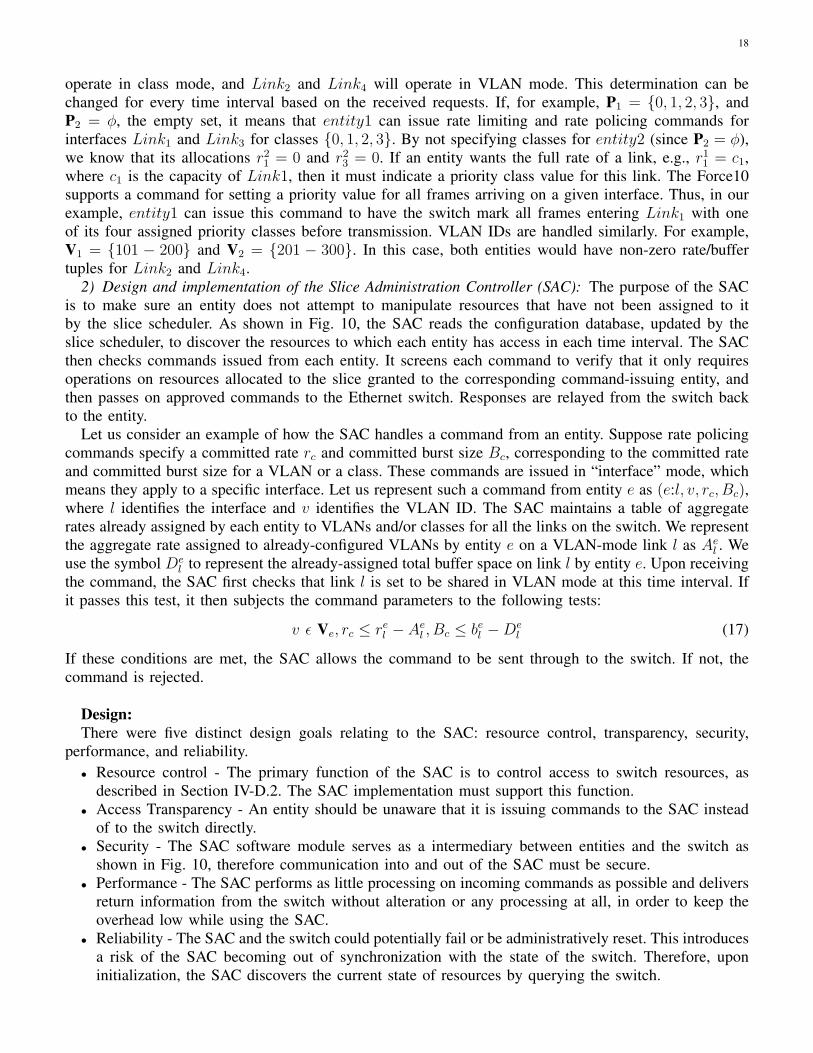
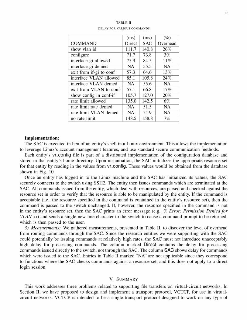
TABLE II
DELAY FOR VARIOUS COMMANDS
(ms) (ms) (%)COMMAND Direct SAC Overheadshow vlan id 111.7 140.8 26%configure 71.7 73.8 3%interface gi allowed 75.9 84.5 11%interface gi denied NA 55.5 NAexit from if-gi to conf 57.3 64.6 13%interface VLAN allowed 85.1 105.8 24%interface VLAN denied NA 55.6 NAexit from VLAN to conf 57.1 66.8 17%show config in conf-if 105.7 127.0 20%rate limit allowed 135.0 142.5 6%rate limit rate denied NA 51.5 NArate limit VLAN denied NA 54.9 NAno rate limit 148.5 158.8 7%
Implementation:The SAC is executed in lieu of an entity’s shell in a Linux environment. This allows the implementation
to leverage Linux’s account management features, and use standard secure communication methods.Each entity’s vr config file is part of a distributed implementation of the configuration database and
stored in that entity’s home directory. Upon instantiation, the SAC initializes the appropriate resource setfor that entity by reading in the values from vr config. These values would be obtained from the databaseshown in Fig. 10.
Once an entity has logged in to the Linux machine and the SAC has initialized its values, the SACsecurely connects to the switch using SSH2. The entity then issues commands which are terminated at theSAC. All commands issued from the entity, which deal with resources, are parsed and checked against theresource set in order to verify that the resource is able to be manipulated by the entity. If the command isacceptable (i.e., the resource specified in the command is contained in the entity’s resource set), then thecommand is passed to the switch unchanged. If, however, the resource specified in the command is notin the entity’s resource set, then the SAC prints an error message (e.g., % Error: Permission Denied forVLAN xx) and sends a single new-line character to the switch to cause a command prompt to be returned,which is then passed to the user.
3) Measurements: We gathered measurements, presented in Table II, to discover the level of overheadfrom routing commands through the SAC. Since the research entities we were supporting with the SACcould potentially be issuing commands at relatively high rates, the SAC must not introduce unacceptablyhigh delay for processing commands. The column marked Direct contains the delay for processingcommands issued directly to the switch, not through the SAC. The column SAC shows delay for commandswhich were issued to the SAC. Entries in Table II marked “NA” are not applicable since they correspondto functions where the SAC checks commands against a resource set, and this does not apply to a directlogin session.
V. SUMMARY
This work addresses three problems related to supporting file transfers on virtual-circuit networks. InSection II, we have proposed to design and implement a transport protocol, VCTCP, for use in virtual-circuit networks. VCTCP is intended to be a single transport protocol designed to work on any type of

20
virtual circuit with performance equal to or greater than protocols designed for circuits or connectionlessnetworks. In Section III, we have proposed a multi-class advance-reservation scheduling system thatallows a tradeoff between mean response time and fairness by using an optimization. We have shownhow it can be modeled as a DTMC, and we will solve the system and use simulations to explore how adeployed instance should be configured in order to achieve fairness among classes in terms of call-blockingprobability and mean waiting time. Finally, in Section IV, we demonstrated our published virtualizationarchitecture that allows two logical switches to be created from one physical switch. One logical switchcan support connectionless service, while the other supports connection-oriented services able to offerpredictable network service to applications such as large file transfers.
Fig. 11. Proposed schedule.
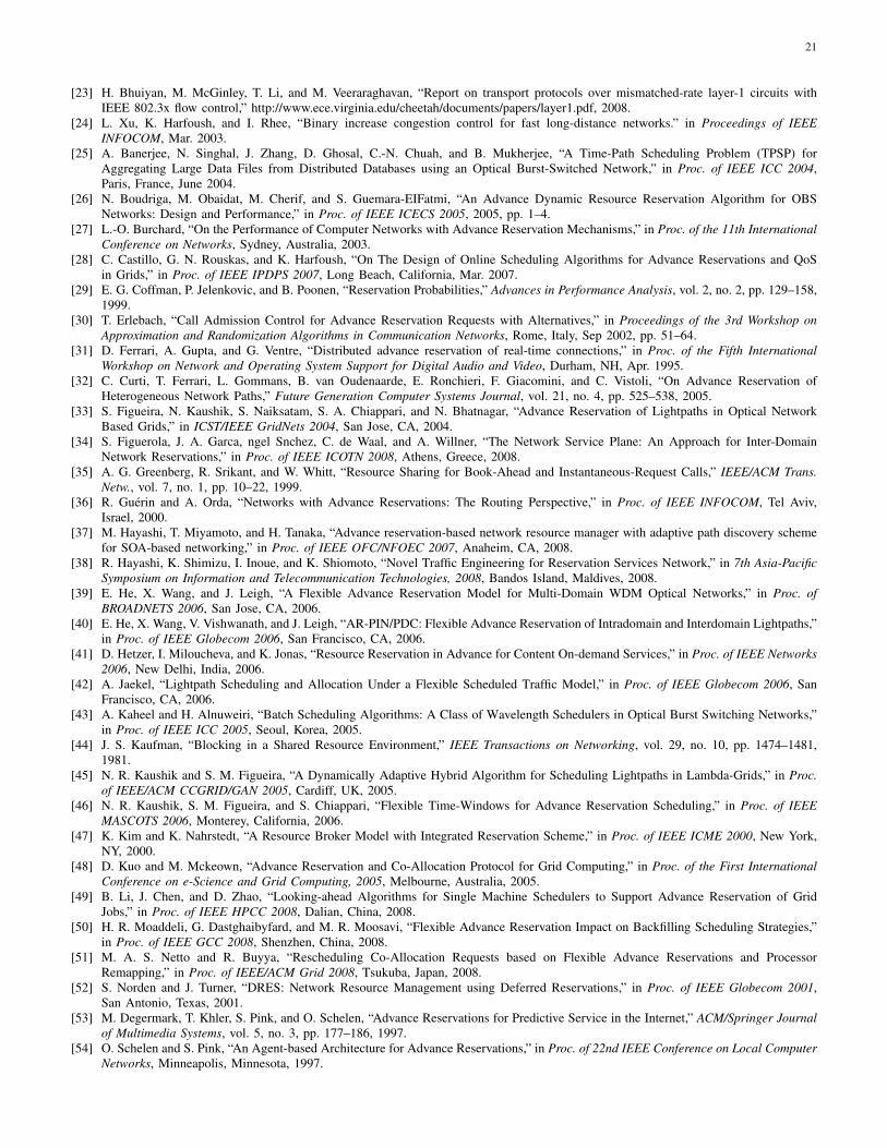
REFERENCES
[1] C. Guok, D. Robertson, E. Chaniotakis, M. Thompson, W. Johnston, and B. Tierney, “A User Driven Dynamic Circuit NetworkImplementation,” in Proceedings of the Distributed Autonomous Network Magagement Systems Workshop, New Orleans, LA, Nov2008.
[2] CHEETAH. [Online]. Available: http://cheetah.cs.virginia.edu[3] X. Fang and M. Veeraraghavan, “On using circuit-switched networks for file transfers,” in Proc. of IEEE Globecom, New Orleans, LA,
Nov. 2008.[4] X. Zhu and M. Veeraraghavan, “Analysis and Design of Book-ahead Bandwidth-Sharing Mechanisms,” IEEE/ACM Transactions on
Networking, vol. 56, no. 12, pp. 2156–2165, Dec. 2008.[5] X. Zhu, M. E. McGinley, T. Li, and M. Veeraraghavan, “An Analytical Model for a Book-ahead Bandwidth Scheduler,” in Proc. of
IEEE Globecom’07, Washington, DC, Nov. 2007.[6] X. Fang, M. Veeraraghavan, M. E. McGinley, and R. W. Gisiger, “An overlay approach for enabling access to dynamically shared
backbone GMPLS networks,” in IEEE ICCCN, Honolulu, Hawaii, Aug 2007.[7] A. P. Mudambi, X. Zheng, and M. Veeraraghavan, “A Transport Protocol for Dedicated End-to-End Circuits,” in Proc. of IEEE ICC
2006, Istanbul, Turkey, June 2006.[8] Internet2. [Online]. Available: http://www.internet2.edu/[9] ESnet. [Online]. Available: http://www.es.net/
[10] Internet2 Dynamic Circuit Network. [Online]. Available: http://internet2.edu/network/dc/[11] W. E. Johnston. Networking for the Future of DOE Science. [Online]. Available: http://www.es.net/ESnet4/
ESnet4-Networking-for-the-Future-of-Science-2008-02-09-FORTH-Crete.ppt[12] V. Jacobson, “Congestion Avoidance and Control,” in Proceedings of SIGCOMM, Stanford, CA, Aug. 1988.[13] Generic Framing Protocol, ITU Std. G.7041/Y.1303, Dec. 2001.[14] BWdetail: A bandwidth tester with detailed reporting. [Online]. Available: http://www.ece.virginia.edu/cheetah/software/software.html#
bwdetail[15] bonnie++. [Online]. Available: http://www.die.net/doc/linux/man/man8/bonnie++.8.html[16] interbench: Linux interactivity benchmark. [Online]. Available: http://members.optusnet.com.au/ckolivas/interbench/[17] S. Iren, P. D. Amer, and P. T. Conrad, “The Transport Layer: Tutorial and Survey,” ACM Computing Surveys, vol. 31, no. 5, 1999.[18] D. D. Clark, M. L. Lambert, and L. Zhang, “NETBLT: A Bulk Data Transfer Protocol,” IETF RFC 998, Mar. 1987.[19] R. M. Sanders and A. C. Weaver, “The Xpress Transfer Protocol (XTP) - A Tutorial,” SIGCOMM Comput. Commun. Rev., vol. 20,
no. 5, pp. 67–80, 1990.[20] T. Moors and M. Veeraraghavan, “Specification of (and reasoning behind) Zing: A transport protocol for file transfers over circuits,”
CATT Technical Report, Polytechnic University, New York, Jan. 2001.[21] X. Zheng, A. P. Mudambi, and M. Veeraraghavan, “FRTP: Fixed Rate Transport Protocol - A modified version of SABUL for end-to-end
circuits,” in Pathnets Workshop, held in conjunction with Broadnets 2004, San Jose, CA, Oct. 2004.[22] M. Mathis, J. Heffner, and R. Reddy, “Web100: Extended TCP Instrumentation.” ACM Communications Review, July 2003.
21
[23] H. Bhuiyan, M. McGinley, T. Li, and M. Veeraraghavan, “Report on transport protocols over mismatched-rate layer-1 circuits withIEEE 802.3x flow control,” http://www.ece.virginia.edu/cheetah/documents/papers/layer1.pdf, 2008.
[24] L. Xu, K. Harfoush, and I. Rhee, “Binary increase congestion control for fast long-distance networks.” in Proceedings of IEEEINFOCOM, Mar. 2003.
[25] A. Banerjee, N. Singhal, J. Zhang, D. Ghosal, C.-N. Chuah, and B. Mukherjee, “A Time-Path Scheduling Problem (TPSP) forAggregating Large Data Files from Distributed Databases using an Optical Burst-Switched Network,” in Proc. of IEEE ICC 2004,Paris, France, June 2004.
[26] N. Boudriga, M. Obaidat, M. Cherif, and S. Guemara-EIFatmi, “An Advance Dynamic Resource Reservation Algorithm for OBSNetworks: Design and Performance,” in Proc. of IEEE ICECS 2005, 2005, pp. 1–4.
[27] L.-O. Burchard, “On the Performance of Computer Networks with Advance Reservation Mechanisms,” in Proc. of the 11th InternationalConference on Networks, Sydney, Australia, 2003.
[28] C. Castillo, G. N. Rouskas, and K. Harfoush, “On The Design of Online Scheduling Algorithms for Advance Reservations and QoSin Grids,” in Proc. of IEEE IPDPS 2007, Long Beach, California, Mar. 2007.
[29] E. G. Coffman, P. Jelenkovic, and B. Poonen, “Reservation Probabilities,” Advances in Performance Analysis, vol. 2, no. 2, pp. 129–158,1999.
[30] T. Erlebach, “Call Admission Control for Advance Reservation Requests with Alternatives,” in Proceedings of the 3rd Workshop onApproximation and Randomization Algorithms in Communication Networks, Rome, Italy, Sep 2002, pp. 51–64.
[31] D. Ferrari, A. Gupta, and G. Ventre, “Distributed advance reservation of real-time connections,” in Proc. of the Fifth InternationalWorkshop on Network and Operating System Support for Digital Audio and Video, Durham, NH, Apr. 1995.
[32] C. Curti, T. Ferrari, L. Gommans, B. van Oudenaarde, E. Ronchieri, F. Giacomini, and C. Vistoli, “On Advance Reservation ofHeterogeneous Network Paths,” Future Generation Computer Systems Journal, vol. 21, no. 4, pp. 525–538, 2005.
[33] S. Figueira, N. Kaushik, S. Naiksatam, S. A. Chiappari, and N. Bhatnagar, “Advance Reservation of Lightpaths in Optical NetworkBased Grids,” in ICST/IEEE GridNets 2004, San Jose, CA, 2004.
[34] S. Figuerola, J. A. Garca, ngel Snchez, C. de Waal, and A. Willner, “The Network Service Plane: An Approach for Inter-DomainNetwork Reservations,” in Proc. of IEEE ICOTN 2008, Athens, Greece, 2008.
[35] A. G. Greenberg, R. Srikant, and W. Whitt, “Resource Sharing for Book-Ahead and Instantaneous-Request Calls,” IEEE/ACM Trans.Netw., vol. 7, no. 1, pp. 10–22, 1999.
[36] R. Guerin and A. Orda, “Networks with Advance Reservations: The Routing Perspective,” in Proc. of IEEE INFOCOM, Tel Aviv,Israel, 2000.
[37] M. Hayashi, T. Miyamoto, and H. Tanaka, “Advance reservation-based network resource manager with adaptive path discovery schemefor SOA-based networking,” in Proc. of IEEE OFC/NFOEC 2007, Anaheim, CA, 2008.
[38] R. Hayashi, K. Shimizu, I. Inoue, and K. Shiomoto, “Novel Traffic Engineering for Reservation Services Network,” in 7th Asia-PacificSymposium on Information and Telecommunication Technologies, 2008, Bandos Island, Maldives, 2008.
[39] E. He, X. Wang, and J. Leigh, “A Flexible Advance Reservation Model for Multi-Domain WDM Optical Networks,” in Proc. ofBROADNETS 2006, San Jose, CA, 2006.
[40] E. He, X. Wang, V. Vishwanath, and J. Leigh, “AR-PIN/PDC: Flexible Advance Reservation of Intradomain and Interdomain Lightpaths,”in Proc. of IEEE Globecom 2006, San Francisco, CA, 2006.
[41] D. Hetzer, I. Miloucheva, and K. Jonas, “Resource Reservation in Advance for Content On-demand Services,” in Proc. of IEEE Networks2006, New Delhi, India, 2006.
[42] A. Jaekel, “Lightpath Scheduling and Allocation Under a Flexible Scheduled Traffic Model,” in Proc. of IEEE Globecom 2006, SanFrancisco, CA, 2006.
[43] A. Kaheel and H. Alnuweiri, “Batch Scheduling Algorithms: A Class of Wavelength Schedulers in Optical Burst Switching Networks,”in Proc. of IEEE ICC 2005, Seoul, Korea, 2005.
[44] J. S. Kaufman, “Blocking in a Shared Resource Environment,” IEEE Transactions on Networking, vol. 29, no. 10, pp. 1474–1481,1981.
[45] N. R. Kaushik and S. M. Figueira, “A Dynamically Adaptive Hybrid Algorithm for Scheduling Lightpaths in Lambda-Grids,” in Proc.of IEEE/ACM CCGRID/GAN 2005, Cardiff, UK, 2005.
[46] N. R. Kaushik, S. M. Figueira, and S. Chiappari, “Flexible Time-Windows for Advance Reservation Scheduling,” in Proc. of IEEEMASCOTS 2006, Monterey, California, 2006.
[47] K. Kim and K. Nahrstedt, “A Resource Broker Model with Integrated Reservation Scheme,” in Proc. of IEEE ICME 2000, New York,NY, 2000.
[48] D. Kuo and M. Mckeown, “Advance Reservation and Co-Allocation Protocol for Grid Computing,” in Proc. of the First InternationalConference on e-Science and Grid Computing, 2005, Melbourne, Australia, 2005.
[49] B. Li, J. Chen, and D. Zhao, “Looking-ahead Algorithms for Single Machine Schedulers to Support Advance Reservation of GridJobs,” in Proc. of IEEE HPCC 2008, Dalian, China, 2008.
[50] H. R. Moaddeli, G. Dastghaibyfard, and M. R. Moosavi, “Flexible Advance Reservation Impact on Backfilling Scheduling Strategies,”in Proc. of IEEE GCC 2008, Shenzhen, China, 2008.
[51] M. A. S. Netto and R. Buyya, “Rescheduling Co-Allocation Requests based on Flexible Advance Reservations and ProcessorRemapping,” in Proc. of IEEE/ACM Grid 2008, Tsukuba, Japan, 2008.
[52] S. Norden and J. Turner, “DRES: Network Resource Management using Deferred Reservations,” in Proc. of IEEE Globecom 2001,San Antonio, Texas, 2001.
[53] M. Degermark, T. Khler, S. Pink, and O. Schelen, “Advance Reservations for Predictive Service in the Internet,” ACM/Springer Journalof Multimedia Systems, vol. 5, no. 3, pp. 177–186, 1997.
[54] O. Schelen and S. Pink, “An Agent-based Architecture for Advance Reservations,” in Proc. of 22nd IEEE Conference on Local ComputerNetworks, Minneapolis, Minnesota, 1997.

22
[55] ——, “Resource sharing in advance reservation agents,” Journal of High Speed Networks, Special issue on Multimedia Networking,vol. 7, no. 3, 1998.
[56] K. Rajah, S. Ranka, and Y. Xia, “Advance Reservation and Scheduling for Bulk Transfers in Research Networks,” IEEE Transactionson Parallel and Distributed Systems, to appear.
[57] W. Reinhardt, “Advance Reservation of Network Resources for Multimedia Applications,” in Proceedings of the International Workshopon Advanced Teleservices and High-Speed Communication Architectures (IWACA), Heidelberg, Germany, 1994.
[58] E. Schill, S. Khn, and F. Breiter, “Resource Reservation in Advance in Heterogeneous Networks with Partial ATM Infrastructures,” inProc. of IEEE INFOCOM, 1997, pp. 612–619.
[59] S. Schmidt and J. Kunegis, “Scalable Bandwidth Optimization in Advance Reservation Networks,” in Proc. of IEEE ICON 2007, Nov.2007, pp. 95–100.
[60] W. Smith, I. Foster, and V. Taylor, “Scheduling with Advanced Reservations,” in Proc. of IPDPS 2000, Cancun, Mexico, 2000.[61] C.-N. Chuah, L. Subramanian, R. H. Katz, and A. D. Joseph, “QoS Provisioning using a Clearing House Architecture,” in Proc. of
IWQOS 2000, Pittsburgh, PA, 2000.[62] S. Tanwir, L. Battestilli, H. Perros, and G. Karmous-Edwards, “Dynamic Scheduling of Network Resources with Advance Reservations
in Optical Grids,” Int. J. Netw. Manag., vol. 18, no. 2, pp. 79–105, 2008.[63] J. Ni, D. H. Tsang, S. Tatikonda, and B. Bensaou, “Optimal and Structured Call Admission Control Policies for Resource-Sharing
Systems,” IEEE Transactions on Communications, vol. 55, no. 1, pp. 158–170, 2007.[64] H. Lee, M. Veeraraghavan, H. Li, and E. K. P. Chong, “Lambda scheduling algorithm for file transfers on high-speed optical circuits,”
in Proc. of IEEE CCGrid 2004, Chicago, IL, 2004.[65] J. T. Virtamo, “A Model of Reservation Systems,” IEEE Transactions on Communications, vol. 40, pp. 109–118, 1992.[66] T. D. Wallace and A. Shami, “Connection Management Algorithm for Advance Lightpath Reservation in WDM Networks,” in Proc.
of BROADNETS 2007, Raleigh, NC, 2007.[67] T. Wallace, A. Shami, and C. Assi, “Scheduling advance reservation requests for wavelength division multiplexed networks with static
traffic demands,” IET Communications, vol. 2, pp. 1023–1033, 2008.[68] P. Wieder, O. Waldrich, and W. Ziegler, “Advanced Techniques for Scheduling, Reservation, and Access Management for Remote
Laboratories,” in Proc. of the Second International Conference on e-Science and Grid Computing, 2006, Amsterdam, Netherlands,2006.
[69] L. C. Wolf and R. Steinmetz, “Concepts for Resource Reservation in Advance,” Multimedia Tools Appl., vol. 4, no. 3, pp. 255–278,1997.
[70] L. Wu, C. Wu, J. Cui, and J. Xing, “An Adaptive Advance Reservation Mechanism for Grid Computing,” in Proc. of PDCAT 2005,Dalian, China, 2005.
[71] J. Yin, Y. Wang, M. Hu, and C. Wu, “Predictive Admission Control Algorithm for Advance Reservation in Equipment Grid,” in Proc.of the IEEE International Conference on Services Computing (SCC), Honolulu, Hawaii, 2008.
[72] J. Zheng and H. T. Mouftah, “A Framework for Supporting Advance Reservation Service in GMPLS-based WDM Networks,” in Proc.of PACRIM 2003, Victoria, B.C., Canada, 2003.
[73] ——, “Routing and Wavelength Assignment for Advance Reservation in Wavelength-Routed WDM Optical Networks,” in Proc. ofICC 2002, New York, NY, 2002.
[74] ——, “Supporting Advance Reservations in Wavelength-Routed WDM Networks,” in Proc. of ICCCN 2001, Scottsdale, Arizona, 2001.[75] J. Zheng, B. Zhang, and H. T. Mouftah, “Toward Automated Provisioning of Advance Reservation Service in Next-Generation Optical
Internet,” IEEE Communications Magazine, vol. 44, no. 12, pp. 68–74, 2006.[76] M. E. McGinley, T. Li, and M. Veeraraghavan, “On Virtualizing Ethernet Switches,” in IEEE ICCCN, St. Thomas, USVI, Aug 2008.[77] Global Environment for Network Innovations (GENI). [Online]. Available: http://www.geni.net/[78] The VMware Website. [Online]. Available: http://www.wmware.com[79] Microsoft Virtual Server. [Online]. Available: http://www.microsoft.com/windowsserversystem/virtualserver[80] Xen. [Online]. Available: http://xen.xensource.com[81] PlanetLab. [Online]. Available: http://www.planet-lab.org[82] A. Bavier, N. Feamster, M. Huang, L. Peterson, and J. Rexford, “In VINI Veritas: Realistic and Controlled Network Experimentation,”
in SIGCOMM ’06: Proceedings of the 2006 conference on Applications, technologies, architectures, and protocols for computercommunications. New York, NY, USA: ACM Press, 2006, pp. 3–14.
[83] J. Turner. A proposed architecture for the GENI backbone platform. [Online]. Available: http://www.geni.net/GDD/GDD-06-09.pdf[84] Cisco VFrame Data Center 1.1. [Online]. Available: http://www.cisco.com/en/US/products/ps8463/index.html[85] M. Kolon, “Intelligent logical router service,” White Paper, Juniper. [Online]. Available: http://www.juniper.net/solutions/literature/
white\ papers/200097.pdf[86] “Cisco XR 12000 series service separation architecture tests,” White Paper, EANTC, May 2005. [Online]. Available:
http://www.eantc.de/fileadmin/eantc/downloads/test\ reports/2003-2005/EANTC-Summary-Report-Cisco-12kXR.FINAL.pdf


![+and destination - aqwam.staff.jak-stik.ac.idaqwam.staff.jak-stik.ac.id/files/keamanan-komputer[3].pdf5 Virtual circuit packet delivery: (analog dengan telephone network) virtual circuit](https://img.pdfslide.us/doc/110x75/5d5b389a88c993b8138bde5d/and-destination-aqwamstaffjak-stikac-3pdf5-virtual-circuit-packet-delivery.jpg)