Embed Size (px)
Citation preview

Aalborg Universitet
On the Stability of Power Electronics-Dominated Systems
Challenges and Potential Solutions
Peng, Qiao; Jiang, Qin; Yang, Yongheng; Liu, Tianqi; Wang, Huai; Blaabjerg, Frede
Published in:IEEE Transactions on Industry Applications
DOI (link to publication from Publisher):10.1109/TIA.2019.2936788
Creative Commons LicenseCC BY 4.0
Publication date:2019
Document VersionPublisher's PDF, also known as Version of record
Link to publication from Aalborg University
Citation for published version (APA):Peng, Q., Jiang, Q., Yang, Y., Liu, T., Wang, H., & Blaabjerg, F. (2019). On the Stability of Power Electronics-Dominated Systems: Challenges and Potential Solutions. IEEE Transactions on Industry Applications, 55(6),7657-7670. [8809097]. https://doi.org/10.1109/TIA.2019.2936788
General rightsCopyright and moral rights for the publications made accessible in the public portal are retained by the authors and/or other copyright ownersand it is a condition of accessing publications that users recognise and abide by the legal requirements associated with these rights.
? Users may download and print one copy of any publication from the public portal for the purpose of private study or research. ? You may not further distribute the material or use it for any profit-making activity or commercial gain ? You may freely distribute the URL identifying the publication in the public portal ?
Take down policyIf you believe that this document breaches copyright please contact us at [email protected] providing details, and we will remove access tothe work immediately and investigate your claim.
Downloaded from vbn.aau.dk on: December 05, 2021
IEEE TRANSACTIONS ON INDUSTRY APPLICATIONS, VOL. 55, NO. 6, NOVEMBER/DECEMBER 2019 7657
On the Stability of Power Electronics-DominatedSystems: Challenges and Potential Solutions
Qiao Peng , Student Member, IEEE, Qin Jiang, Yongheng Yang , Senior Member, IEEE,Tianqi Liu, Senior Member, IEEE, Huai Wang , Senior Member, IEEE, and Frede Blaabjerg , Fellow, IEEE
Abstract—The modern power system is becoming more com-plicated due to the ever increasing penetration of power electron-ics, which is referred to as a power-electronics-dominated system(PEDS). In this case, the analysis, control, and operation of theentire power system should tone with the energy-paradigm transi-tion pace, where the challenges should be properly tackled. Afterthe brief introduction of grid-connected converters, this articleexplores stability challenges of PEDSs, especially on the low inertiaissue and multitimescale characteristics, as well as the dynamicswhen connected to weak grids. The low inertia issue is consideredas one of great challenges that power electronics introduce to theconventional power grid. Accordingly, the stability issues of PEDSsare discussed. The exploration reveals that the multitimescalecoupling among various control loops and the mutual effects ofmultiple converters demand much more attention than ever before.The coordinated control of converters for the global stability ofPEDSs is also summarized, part of which offers the possibilityto solve the inertia problem. This article serves as an inspirationon potential solutions to these issues. In order to provide a moreintuitive impression of the inertia problem in PEDSs, a case studyis exemplified to highlight the analysis and discussion.
Index Terms—Low-inertia systems, multitimescale analysis,mutual effect, modeling, power-electronics-dominated systems(PEDSs), power electronic converters, stability and control, virtualinertia.
NOMENCLATURE
AGC Automatic generation control.AVR Automatic voltage regulator.CCM Component connection method.DFIG Doubly fed induction generator.DPGS Distributed power generation system.ESS Energy storage system.
Manuscript received December 27, 2018; revised June 11, 2019; acceptedAugust 16, 2019. Date of publication August 20, 2019; date of current versionNovember 7, 2019. Paper 2018-HPC-1169.R1, presented at the 2018 IEEEIndustry Applications Society Annual Meeting (IAS), Portland, OR, USA, Sep.23–27, and approved for publication in the IEEE TRANSACTIONS ON INDUSTRY
APPLICATIONS by the High Performance Power Electronic Converters: Topolo-gies, Control, and Devices of the IEEE Industry Applications Society. This workwas supported by THE VELUX FOUNDATIONS under the VILLUM Inves-tigator Grant REPEPS (Award Ref. No.: 00016591). (Corresponding author:Yongheng Yang.)
Q. Peng, Y. Yang, H. Wang, and F. Blaabjerg are with the Departmentof Energy Technology, Aalborg University, Aalborg 9220, Denmark (e-mail:[email protected]; [email protected]; [email protected]; [email protected]).
Q. Jiang and T. Liu are with the College of Electrical Engineering, SichuanUniversity, Chengdu 610065, China (e-mail: [email protected];[email protected]).
Color versions of one or more of the figures in this article are available onlineat http://ieeexplore.ieee.org.
Digital Object Identifier 10.1109/TIA.2019.2936788
FSM Frequency sensitive mode.IR Inertia response.LCC Line-commutated converter.LCC-HVDC LCC-based high voltage direct current.MIESCR Multiinfeed interactive effective short-circuit
ratio.MIIF Multiinfeed interaction factor.MPC Model predictive control.MPP Maximum power point.MPPT Maximum power point tracking.MTDC Multiterminal direct current.OPF Optimal power flow.PCC Point of common -coupling.PEDS Power electronics-dominated system.PI Proportional-integral.PIV Power-internal voltage.PLL Phase-locked loop.PMSG Permanent-magnet synchronous generator.PSS Power system stabilizer.PV Photovoltaic.PWM Pulsewidth modulation.RSC Rotor-side converter.SG Synchronous generator.SRF Synchronous reference frame.TSO Transmission system operator.VSC Voltage source converter.VSG Virtual synchronous generator.
I. INTRODUCTION
THE current energy network is being retrofitted with morerenewable energy sources like wind and solar energy [1],
[2]. By 2018, the global installed capacity of the wind powerachieved 592 GW, and over 300 GW of new capacity is expectedto be added until 2023 [3]. On the other hand, the solar power,mainly integrated via the PV technology, remains also at ahigh growth rate. By the end of 2018, the global cumulativeinstalled PV capacity reached 509 GW [4]. In the conventionalpower grid, the source, network, and load are mainly electromag-netic equipment, e.g., SG, transformers, and induction motors.However, unlike to that, the modern power grid is increasinglyintegrated with renewable energy, heavily relying on static powerelectronics converters [5]. This makes the entire power gridmore complicated. Moreover, in this case, the boundary betweenac and dc grids becomes indistinct in such highly aggregated
This work is licensed under a Creative Commons Attribution 4.0 License. For more information, see https://creativecommons.org/licenses/by/4.0/
7658 IEEE TRANSACTIONS ON INDUSTRY APPLICATIONS, VOL. 55, NO. 6, NOVEMBER/DECEMBER 2019
Fig. 1. Highly aggregated PEDS.
PEDSs, consisting of wind farms, PV plants, SGs, inductionmotors, etc., as exemplified in Fig. 1.
With this background and the continuous evolution of theenergy paradigms, the modeling and dynamic analysis of PEDSsbecome more important than ever before. This ensures pro-viding theoretical foundation and technological support for thecost-effective enhancement of the entire power system in termsof availability, stability, and reliability. For instance, in theliterature, it has been demonstrated that the stability concernof MTDC systems or dc microgrids is one of the emergingissues, requiring much attention [6]–[8]. However, the focus wasmainly put on the analysis on the dc side, mainly contributing tothe coordinated control strategy for the power sharing in the dcgrid [9], and the entire dc grid was taken as a large generatingunit for the ac grid. Similarly, the focus of most of the researchon the ac microgrids is mainly on the power sharing amongconverters [10], [11]. The cross-effect or mutual interactionsbetween the ac and dc grids have not been fully explored. Inaddition, attempts have been made to address the harmonic res-onance issue in power converter systems [12], e.g., the CCM andimpedance-based approach [13], and the interaction-admittancemodel method [14]. However, a complete picture and a commonunderstanding of the multiconverter system interactions have notyet been fully discussed. This becomes more important, as thepower electronic penetration is still increasing.
In fact, power electronics have fast dynamics, but also theintegration of multiple power converters brings instability. Theroot cause of the system instability is complicated and crossaffected, which has not been thoroughly clarified yet. One ofthe common and critical reasons is the lack of physical inertia.Therefore, many measures have been taken to enhance the inertiaof power converters. For instance, the power converter can becontrolled to mimic the behaviors of SGs, whose inertia isprovided by the rotating mass. This concept is known as theVSG and the emulated inertia is referred to as virtual inertia [15],
[16]. The relationship between the virtual inertia of VSGs andthe system transient stability was presented in [17], followingwhich a self-adaptive inertia and damping control was developedin [18]. It should be noted that the analysis or control strategydepends on an assumption that the inertia is provided by a largeESS or alike, i.e., the inertia requirement can be always satisfied,which is, however, not economical or practical. An alternativeto emulate inertia can be achieved through the dc-link capacitor(notably, it can also be considered as a storage device) of thepower converters [19], [20]. This inertia provision scheme hasbeen effectively demonstrated for the short-term frequency sup-port. In addition, the dc-link capacitor lifetime performance maybe affected when the inertia emulation is enabled. Nonetheless,the virtual inertia should be further enhanced in a way that thewell-established theory and control methods for the conventionalSGs may be employed.
Consequently, additional attention has been paid to expressthe virtual inertia-related external characteristics of power con-verters with vector control strategies by a universal model. Forexample, in [21], a small-signal model of power converterswith a vector control strategy was introduced to illustrate theimpact of system parameters and control loops on the dc-linkvoltage stability. In [22], the concept of a multitimescale controlloop was depicted, based on which a model reflecting the PIVcharacteristics of converters was developed, and the stabilityanalysis was subsequently achieved in [23]. Although the modelmay be overcomplicated and it is unnecessary to strictly modelthe converter in analogy with an SG, the modeling conceptin a universal way to represent the power converter externalcharacteristics is instructive and meaningful.
To shed light on the aforementioned issues, grid-connectedpower converters with different control strategies are discussedin this article. Based on our previous study [24]–[26], focuses areput on the associated stability issues, including the virtual inertiacharacteristics, the interaction between the power converters and
PENG et al.: ON THE STABILITY OF PEDSs: CHALLENGES AND POTENTIAL SOLUTIONS 7659
the ac grid, and the mutual effect among multiple converters.Prospective solutions are briefed for future studies, which maylay the foundation for the control system designs of the PEDSs.The rest of this article is organized as follows. Section II intro-duces the control of the grid-connected converters. Section IIIemphasizes the stability issues of the grid-connected converters,where the priority is the low inertia issue. The stability chal-lenges in PEDSs are then depicted in Section IV, where, seenfrom the authors’ perspective and understanding, possible solu-tions are put forward. In order to afford intuitive impression onthe control interaction in the systems, a case study is given in Sec-tion V. Finally, concluding remarks are provided in Section VI.
II. CONTROL AND MODELING OF GRID-CONNECTED
CONVERTERS
This section will introduce the control strategies of powerelectronic converters. Among various control schemes, non-linear control methods are attracting more popularity. One ofthe most studied methods is the predictive control, includingthe deadbeat control [27], general MPC [28], and modifiedpredictive controls [29], [30]. Sliding mode control and artifi-cial intelligence-based control are introduced to grid-connectedconverters as well [31], [32]. However, most of these nonlinearcontrol methods require enormous computational burden. Thecomplicated mathematical description makes it difficult to ex-plain and further solve potential instability issues coming withthe nonlinearity [33]. Although most of the nonlinear controllersproposed for the power converters are validated in laboratories,practical applications are still not widespread. Thus, the impactof nonlinear control methods on PEDS stability is not specifi-cally discussed in this article. At present, the conventional linearcontrols are still the most mature and widely applied controlmethods. Notably, the following discussion on the stabilityissues and potential solutions may be also applicable to nonlinearcontrol-based systems.
A. Basic Control
In general, the power converters can be divided into threecategories according to their control strategies or objectives, i.e.,grid-feeding, grid-supporting, and grid-forming converters [34].The grid-feeding converters usually operate as current sourcesto inject active and/or reactive power to the grid [35], [36]. Thegrid-forming converters can only operate in the islanded mode[37], while the grid-supporting ones are able to provide ancillaryservices to the grid (e.g., frequency regulation), being operatedas either current or voltage sources [34]. In the PEDS, the systemis significantly scaled up, and the diversity of power converterschallenges the modeling, analysis, control, and operation of theentire system. The generality of power converters with variouscontrol strategies as aforementioned should thus be explored.
For the linear-controlled grid-connected converters, espe-cially those for the large-scale renewable energy integrationand long-distance power transmission, the dual-loop vector con-trol strategy is widely used. In fact, in the current VSC-basedprojects in operation, the converters are mostly equipped withthe dual-loop vector control strategy [38]–[40]. In general, the
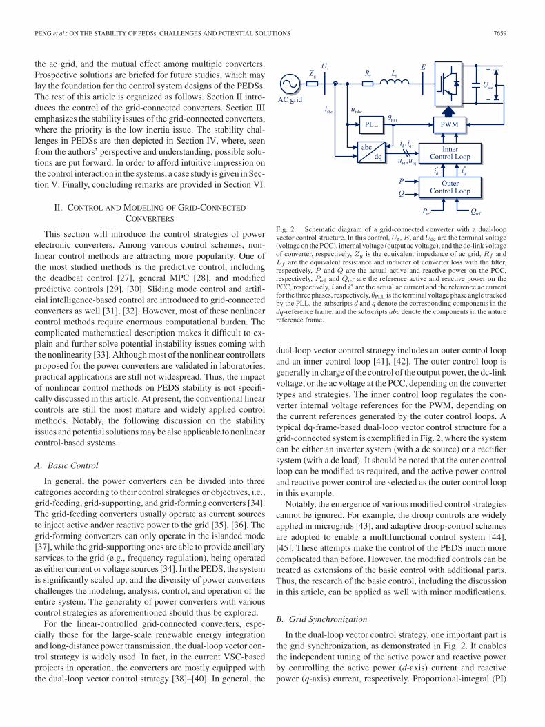
Fig. 2. Schematic diagram of a grid-connected converter with a dual-loopvector control structure. In this control, Ut, E, and Udc are the terminal voltage(voltage on the PCC), internal voltage (output ac voltage), and the dc-link voltageof converter, respectively, Zg is the equivalent impedance of ac grid, Rf andLf are the equivalent resistance and inductor of converter loss with the filter,respectively, P and Q are the actual active and reactive power on the PCC,respectively, Pref and Qref are the reference active and reactive power on thePCC, respectively, i and i∗ are the actual ac current and the reference ac currentfor the three phases, respectively, θPLL is the terminal voltage phase angle trackedby the PLL, the subscripts d and q denote the corresponding components in thedq-reference frame, and the subscripts abc denote the components in the naturereference frame.
dual-loop vector control strategy includes an outer control loopand an inner control loop [41], [42]. The outer control loop isgenerally in charge of the control of the output power, the dc-linkvoltage, or the ac voltage at the PCC, depending on the convertertypes and strategies. The inner control loop regulates the con-verter internal voltage references for the PWM, depending onthe current references generated by the outer control loops. Atypical dq-frame-based dual-loop vector control structure for agrid-connected system is exemplified in Fig. 2, where the systemcan be either an inverter system (with a dc source) or a rectifiersystem (with a dc load). It should be noted that the outer controlloop can be modified as required, and the active power controland reactive power control are selected as the outer control loopin this example.
Notably, the emergence of various modified control strategiescannot be ignored. For example, the droop controls are widelyapplied in microgrids [43], and adaptive droop-control schemesare adopted to enable a multifunctional control system [44],[45]. These attempts make the control of the PEDS much morecomplicated than before. However, the modified controls can betreated as extensions of the basic control with additional parts.Thus, the research of the basic control, including the discussionin this article, can be applied as well with minor modifications.
B. Grid Synchronization
In the dual-loop vector control strategy, one important part isthe grid synchronization, as demonstrated in Fig. 2. It enablesthe independent tuning of the active power and reactive powerby controlling the active power (d-axis) current and reactivepower (q-axis) current, respectively. Proportional-integral (PI)

7660 IEEE TRANSACTIONS ON INDUSTRY APPLICATIONS, VOL. 55, NO. 6, NOVEMBER/DECEMBER 2019
controllers are generally adopted in the dq-frame control sys-tem. It is worth mentioning that actually, the transformationof the natural abc-frame currents into the dq-frame builds theconnection between power converters and conventional powerelectrical devices such as SGs. Thus, the grid voltage phaseangle information is important to achieve the reference frametransformation, and it is generally extracted by means of a PLL[46]. Among the prior-art PLL techniques, the SRF-PLL isthe most commonly used method. It gives a fast and precisedetection of grid voltage phase angle [47]–[49].
Although the basic SRF-PLL works well under the balancedgrid conditions, it would be weak when the grid operationbecomes unbalanced, as the positive-sequence components de-tected by the SRF-PLL may be affected by the negative-sequencecomponents [50]. Moreover, the SRF-PLL is very sensitive tophase angle jumps of the grid voltage, which decreases the sta-bility of converters under disturbances [51]. Despite the diversityof PLL technologies, the interaction between the PLL and othercontrol loops, and the stability problem caused by the PLL underweak grids are important as well. This will be discussed in thefollowing sections.
C. Universal Modeling of Grid-Connected Converters
Modeling is an essential tool for stability analysis. For powerconverters, two typical modeling methods are used, i.e., theimpedance-based and the state-space modeling. The impedance-based method is friendly in reduction of the calculation burdenand is independent on system topologies [13], [52]. As thefrequency characteristics of power converters and the gridscan be obtained based on their equivalent impedances in thefrequency domain, this method attracts much interest in dealingwith harmonic problems [53]–[55]. Another method is the state-space model, of which the advantages include that the physicalmeaning of the model and the relationship between variablesare clear, and the well-developed analysis tools based on thestate-space theory can be used conveniently [56], [57].
The state-space model is more difficult to obtain mathe-matically, as the model of the converters is generally coupledwith the grid, i.e., the parameters of the grid may be presentin the converter’s model. This is obviously not desired in theanalysis of the PEDS. Although the impedance-based method isable to independently model the converter and the grid withoutparameters coupling, it is somehow troublesome to measure andcalculate the impedance when there is a large amount of powerconverters. Thus, how to model the converters by addressingthese issues is a challenge. Continuous research efforts havethus been devoted into the modeling. For instance, a state-spacemodeling method for grid-connected converters without gridparameters was introduced in [58], based on which a modelconsidering effects of dead time and time delays was developedin [59]. This modeling method enables the universal stabilityanalysis of the grid-connected converters.
In addition to the modeling method, the generality of themodel is another important concern. As described in the lastsection, the control strategies of converters are complicated.The dynamics of converters differ with the control strategies.
Fig. 3. Small-signal swing equation of an SG, where ΔP is the unbalancedpower between the mechanical power and electromagnetic power, where Pm,Pe, H , ω, D, and δ are the mechanical power (provided by the prime mover),electromagnetic power (output power), inertia constant, angular frequency,damping factor, and power angle of the SG, correspondingly, and ω0 is therated angular frequency.
For the grid-feeding converters, the control objectives are theiroutput active and reactive power, while for the grid-formingconverters, they are designed to regulate the voltage amplitudeand frequency of the local grid. When these converters areconnected to the same grid, what parameters and tools can beused to assess the stability of the converters and further thesystem should be discussed cautiously. That is to say, the gridsneed to determine the necessary information from converters.In this way, the stability of the PEDSs can be conducted byaggregating the universal converter model.
III. STABILITY OF GRID-CONNECTED CONVERTERS
Before discussing the stability of PEDSs, the stability ofgrid-connected converters should be addressed. This section willillustrate the stability of grid-connected converters from variousaspects and explore potential solutions to the stability.
A. Power-Internal Voltage Characteristic
In the conventional multi-SG-based power systems, two ofthe most important stability issues include the power anglestability and voltage stability, which are closely related to theactive power and reactive power, respectively [60], [61]. This isbecause the power distribution of the system can be adjusted byregulating the power angle of the generators. This self-adjustingprocess is achieved by the rotor motion in SGs, which is de-scribed as
⎧⎪⎨
⎪⎩
Pm − Pe = Hωdω
dt+DΔω
dδ
dt= ω − ω0
(1)
being the swing equation. Fig. 3 further presents the swingequation of an SG. As observed in Fig. 3, the output of theswing equation, i.e., the internal voltage phase angle, determinesthe grid power distribution, and then, the active power is fedback to the swing equation as an input. Additionally, as seenin Fig. 3, the inertia H decides the frequency response ofthe SG. Moreover, the inertia characteristic can be analyzed bythe relationship between the active power P and the internal

PENG et al.: ON THE STABILITY OF PEDSs: CHALLENGES AND POTENTIAL SOLUTIONS 7661
voltage phase angle δ, also referred to as the PIV characteristicof an SG. Accordingly, it may be valuable to model the powerconverters representing their PIV characteristics, which devotesto the overall analysis, especially the inertia issue of the PEDS.
For instance, attempts were made to establish the universalmodel that can reflect the PIV characteristics of power convertersin [21] and [22]. In these cases, the relationship between theoutput power and internal voltages was demonstrated. Basedon the model, the impact of control parameters, the converteroperating point, and the grid stiffness on the stability of powerconverters can be investigated. Unfortunately, the application ofthese models for the entire system stability analysis has not beendiscussed. It requires more detailed analysis and modeling.
B. Inertia Characteristics
For the SG, as there is mechanical-rotating mass, large physi-cal inertia may be readily available to buffer the system dynamicresponses. In contrast, for the grid-connected converters withoutmechanical rotors, either additional devices should be adopted orthe control should be retrofitted to provide (virtual) inertia, i.e.,absorb, or compensate for the transient energy; otherwise, thesystem may collapse under severe disturbances [62]. To achieveso, several virtual inertia solutions have been introduced in theliterature, which will be reviewed in the following.
1) Virtual Synchronous Generator With ESS: To address thelow inertia issue, the power converters can be arbitrarily de-signed or controlled to mimic the behavior of SGs, i.e., releas-ing the stored energy to damp the disturbances when needed.The grid-connected power converters operating in this way arereferred to as VSGs. In this case, the inertia can be emulated andalso directly adjusted, which makes it possible and flexible touse the emulated (virtual) inertia to stabilize the entire system[63], [64].
It should be noted that the virtual inertia of a VSG is limitedby the ESS performance, e.g., batteries or supercapacitors [65].The drastic development of ESS technologies is promoting theESS as more viable and popular solutions for inertia support andprimary frequency regulation in the future. However, completelyemulating the power converter to an SG is not always the bestoption, as the inertia increase may sacrifice the advantages ofpower converters, including fast dynamics and high controlla-bility. Thus, it deserves much attention to explore more universalinertia provision schemes in the PEDS.
2) Virtual Inertia From the DC-Link Capacitor: Some at-tempts have been made to seek the balance between inertia em-ulation and control flexibility. Instead of completely modifyingthe control of grid-connected converters, the dc-link capacitor,as an energy storage device, can be adopted to provide virtualinertia. Without additional ESS units, the virtual inertia canbe emulated by charging and discharging the dc-link capacitor[23], [66]. Although the dc-link capacitor is generally unableto deal with large energy storage, it enables flexible frequencysupport from all power converters, especially in small-scale andrelatively weak grids.
To achieve the inertia emulation by the dc-link capacitor, thedc-link voltage control should be modified. When there is energy
unbalance in the grid, the dc-link voltage will be regulated in away to process the energy flow (i.e., emulating the inertia tostabilize the system). During this process, the energy unbalanceis compensated, and the virtual inertia is generated by the dc-linkcapacitor. Clearly, the dc-link voltage control used to simulatethe virtual inertia can be the conventional dual-loop vector con-trol with minor modifications [67], the dc-link voltage-frequencydroop control [20], or the self-synchronized dc-link voltagecontrol [19].
It is worth mentioning that the significance of the virtualinertia from the dc-link capacitor is that it jumps out the limit ofthe VSG. That is, the rest of the power converter modeling andcontrol may remain. As a consequence, it may stimulate furtherresearch in the inertia from complicated PEDSs.
3) Inertia Emulating Control of Renewable Energies: In ad-dition to the virtual inertia from ESSs or dc-link capacitors,inertia can be provided from renewable energy sources. For windturbine systems, especially the DFIG systems, the virtual inertiacan be provided either by the dc-link capacitor or by recouplingthe rotor mass to the grid frequency [68], [69]. More specifically,for the latter solution, the inertia can be generated by the rotatingmass of the DFIG (i.e., control the rotor motion). In this case,a frequency response loop in the MPPT loop of the rotor-sideconverter should be introduced, and the active power referencecan be adjusted following the grid frequency deviation [70], [71].As the DFIG is operating in the MPPT mode in steady state, theinertia from the rotor motion can only deal with under-frequencyconditions [62].
The inertia emulating is also applicable to PV systems, wherethe ESS or dc-link capacitor-based inertia provision is also fea-sible [72], [73]. In this case, the PV system keeps running in theMPPT mode and is barely affected by the frequency deviation,i.e., the PV system is operating as a constant current source with-out any grid support function. However, the output power of PVsystems is fluctuating, and the frequent charging and dischargingof energy storage devices (e.g., batteries and dc-link capacitors)are impractical and not economic-friendly. Thus, how to affordthe virtual inertia by flexible PV output power control is ofinterest.
Various solutions have been reported in the literature. Forinstance, the coordinated frequency support control dependingon the reserved power of PV systems was proposed in [74],where the linear frequency-power droop control and the inertiaresponse control are included. By regulating the PV outputpower under the MPP, a specific amount of power can bereserved for the frequency support. Once the detected frequencyis irregular, the PV unit can flexibly adjust its output power tobalance the energy without the ESS [75]. Furthermore, an inertiaemulating control of PV systems was developed in [76], wherethe PLL is replaced by a self-synchronous loop identical to theSG’s and the frequency regulation loop complies with the swingequation of an SG.
To sum up, the possible inertia emulation/provision fromPEDSs is shown in Table I [20], [62], where Tm and Te arethe input mechanical torque and output electromagnetic torqueof the generator, ωr is the rotating speed of the SG rotor or windturbine rotor, Pdc is the transient power of the energy storage

7662 IEEE TRANSACTIONS ON INDUSTRY APPLICATIONS, VOL. 55, NO. 6, NOVEMBER/DECEMBER 2019
TABLE IPOSSIBLE INERTIA EMULATING METHODS OF DIFFERENT DEVICES IN POWER ELECTRONICS-DOMINATED SYSTEMS
device, Pref is the active power control reference of the RSC, Pand V are the output active power and dc voltage of PV panels,respectively. It should be pointed out that the energy storagedevice in Table I can be the ESS in the VSG system or thedc-link capacitor in regular grid-connected converters. Beyondthe solution in Table I, more extensive exploration is expectedto strengthen the power systems with more and more powerelectronics. In this way, the virtual inertia of power convertersshould be quantitatively identified. By analyzing the inertiacharacteristics, the stability of the grid with power converterscan be assessed [77].
C. Multitimescale Coupling of Control Loops
For a dual-loop vector-controlled converter, the bandwidthof the current control loop is typically designed dependingon the switching frequency. The response of the inner currentloop is generally in the millisecond range, and in contrast, theresponse time of the outer control loop is commonly ten timesslower [78]. Due to the dynamic response distinction of thecontrol loops, the entire control system should be analyzedin different timescales, where the cross-coupling effect shouldbe explored. This concept is known as multitimescale analysis[22], [79].
Under such a background, the instability in a PEDS may beamplified gradually due to the mutual effects among controlloops. For example, the disturbance on the terminal voltage willaffect the phase angle tracked by the PLL. As the dq-frameis generated according to this phase angle, it will affect theperformance of the inner current controller and the dc-linkvoltage stability, and further, the output power of the converter[21]. On the other hand, the controllers in a small timescale maybe designed to damp the disturbances in a large timescale. Forinstance, the low-frequency oscillations, which were conven-tionally damped by the PSS installed in the excitation systemof an SG, can be tackled by additional controllers added on theactive power control loops of LCCs or VSGs [80], [81].
In all, in the PEDS, to understand the mutual effect amongcontrol loops, it is important to model the system to decouplethe control in various timescales in order to develop controlstrategies with ensured system stability. That is, for a particulartimescale, what assumptions can be made and what dynamicscan be ignored should be addressed properly.
D. Stability Problems Due to Grid Stiffness
The grid stiffness is being altered by various factors, e.g., longtransmission lines, solid-state transformers, or highly aggre-gated DPGSs [82]. The decreasing grid stiffness is threateningthe stable operation of PEDSs. For example, when an LCL filteris adopted, the increase in the grid impedance decreases the filterresonance frequency and the system bandwidth, which may yieldharmonic problems or instability [83]. In such a case, the gridimpedance should be considered in the design phase of the filterand the control parameters [52], [82]. More importantly, thePLL performance is significant affected by the grid stiffness.The decreased grid stiffness magnifies the negative effect ofthe PLL on the system damping, and the system is thus morelikely to lose stability [84]. Additionally, it has been revealedthat the interaction between the PLL and control loops has asignificant impact on the system stability [21], [66], [79], [85],[86]. For instance, in [66], a dual-torque analysis method waspresented to explore the impact of ac-bus voltage control onthe dc-link voltage control stability in weak grids. Specifically,the ac-bus voltage control behaves as a lagging regulator forthe dc-bus voltage control by providing phase-lagged dampingand restoring virtual torques to the dc-link voltage stability [66].When the grid stiffness decreases, the damping torque may benegative and the system is more vulnerable to disturbances, i.e.,the ac-bus voltage control worsens the dc-link voltage controlstability.
Notably, it has been verified in [84] that the VSC performsbetter than the LCC when grid stiffness decreases, and thus, theboundary between “weak” and “strong” grids with VSCs should

PENG et al.: ON THE STABILITY OF PEDSs: CHALLENGES AND POTENTIAL SOLUTIONS 7663
Fig. 4. Universal model of multiconverter systems with n VSCs and m loads.
differ from that with LCCs. In that case, with the state-spacemodel, the dynamics of control loops under weak grid conditionscan be assessed, and the control parameters can be designed foroptimal performance, correspondingly.
IV. STABILITY CHALLENGES AND POTENTIAL SOLUTIONS
FOR THE PEDSS
As aforementioned, the PEDSs are complicated with variouspower equipment. In such systems, not only the dynamics ofpower converters should be investigated, but also the mutualeffect among converters and other devices, e.g., wind generators,PV panels, batteries, and SGs, should be addressed. Hence,many challenges to the stability and control emerge. Owingto the specialty of power electronic converters, the stabilityanalysis methods used in multi-SG systems may not be directlyapplied in the PEDSs. On the contrary, experience gained insuch applications can be adopted. Enlightened by the analysis inmulti-SG systems, this section will discuss the challenges (e.g.,due to mutual effects) and potential solutions to the stability inmultiple power converters-based systems.
A. Universal Model-Based Stability Analysis
The converter universal model reflecting the PIV charac-teristics has been discussed in Section III. Accordingly, thePIV characteristic and the stability of the entire PEDS can beassessed, as demonstrated in Fig. 4 [22]. It can be observed inFig. 4 that the most important parameters, i.e., the amplitudeand phase angle of the internal voltage of each power converterare considered in this model. When the universal model isconsidered in an ac grid, the operation matrix of the grid can beobtained, known as the Hessian matrix or the Jacobian matrix.By analyzing the characteristics of the matrix, the mutual effectamong power converters and also the interaction with the ac gridmay be disclosed. Notably, other power devices can be modeledin a similar way, i.e., modeling each device reflecting its PIVcharacteristics, and then, it will be straightforward to investigatethe system stability.
As for the mutual effect among converters and other devices,the analysis methods used in multiinfeed LCC-HVDC systemscan be referenced. For example, in the LCC-based systems, oneof the most important problems is the commutation failure issue,which is generally caused by the grid voltage drops, so the MIIFis adopted to assess the voltage amplitude interaction and furtherthe commutation failure possibility [87]. Inspired by this, thesimilar concepts, such as the multiconverter interaction factor,for the PEDSs can be developed. However, for the VSC-basedsystems, as discussed previously, the interaction on the voltagephase angle may be more attractive, as it accounts for the per-formance of the PLL and thus, the control system. Additionally,another index, e.g., the MIESCR, can also be referenced for thestability analysis under weak grid conditions [88].
B. Cross-Effect of Power Devices in Multitimescale
The multitimescale coupling of control loops in grid-connected converters has been discussed in Section III. However,there are not only grid-connected converters in the PEDSs.As shown in Fig. 1, the controllers or control strategies inthe conventional multi-SG-based systems and renewable en-ergy systems should also be considered when analyzing thecontrol loops coupling in different timescales. For instance, inan SG, the AVR is in the voltage control timescale (hundredsof milliseconds) [89], while its inertia response to frequencyis in the rotor speed control timescale (above seconds). Theconventional low-frequency oscillation damping device—thePSS and the AGC adopted widely in distribution systems areworking in the rotor speed control timescale as well [8], [90].Moreover, with longer response time (above minutes), thereare more control strategies at the dispatching level, includingthe power management strategy, OPF control [91], and activepower reserve coordinated by the TSO [92]. Although the controlstrategies at the dispatching level are with slow response dynam-ics, the impact on the faster control loops cannot be ignored. Forexample, a grid frequency support method of the PV systemwas presented in [74], where the FSM and IR loops were addedin the PV system control. These additional control loops, bothof which were in the rotor speed control timescale, enabled thePV adjusting its output power to support the system frequency,where the reserved power was assigned by the TSO [74]. As asummary, the control timescales are briefly classified in [79] andenriched, as shown in Fig. 5.
It can be seen from Fig. 5 that, due to the sophisticatedcoupling of not only control loops but also power devices, itis more difficult to explore the dynamics of the PEDSs. Evenjust in one power generation unit, the coupling is complicated.For instance, the control of a DFIG-based wind turbine canbe layered into three loops, including the active and reactivecurrent control, dc-link voltage and terminal voltage control, androtational speed control and reactive power control, of which theresponse time is ascending [71].
Some interaction issues have been exemplified in the liter-ature. For example, due to the power exchange of the energystorage elements, there will be mutual effects among the current

7664 IEEE TRANSACTIONS ON INDUSTRY APPLICATIONS, VOL. 55, NO. 6, NOVEMBER/DECEMBER 2019
Fig. 5. Classification of the timescales of the control loops in PEDSs.
controllers of the DFIG wind turbines, PV systems, and VSCs[79]. The interaction between direct-drive PMSGs and weakgrids can cause negative-resistance effect to the system, whichmay trigger subsynchronous oscillations [93]. Furthermore, therotational speed control of the wind turbine may affect the rotormotion of the SG, or the PSS operation [94].
C. Central-Allocated Coordinated Control of Converters
As has been emphasized in the aforementioned, the powerelectronic converter owns high controllability and fast dynamics.Moreover, the output active power and reactive power of thepower converter can be adjusted separately. All of these featuresmake it possible to build up the converter to be a comprehensivecontrol machine in charge of the tasks that are assigned to it.In such a case, the coordination of power converters, includingthe task assignment and controller performance requirement,becomes more vital.
The control of individual grid-connected power convertershas been illustrated in Section II. The droop controls mentionedin Section II are generally decentralized, based on which thegrid support can be effectively achieved. More specifically, theinformation of the neighboring area is collected for the droopcontrol schemes, which then quickly regulate the converteroutputs. This process can be an automatic coordinated controlstrategy, which effectively enhances the system stability [43].However, in the PEDSs, the coordination of power convertersand other power devices cannot be ignored. That is to say, asthere are multiple converters in the system, the role of eachconverter and the contribution of the converter to the grid shouldbe assessed comprehensively. Moreover, the control parametersof the decentralized control, e.g., the droop control, should be setglobally according to the stability assessment of the large-scalepower system.
Much work has been done for the coordinated control strategyin microgrids considering the global system stability, which isknown as the power sharing control [11]. The power sharingcontrol is generally divided into three hierarchical layers, i.e.,the primary control, secondary control, and tertiary control[95]. In the design of each layer, the global system stabil-ity should be considered. An example has been presented in[96], where the voltage droop control parameters are tuned bythe optimal dc-power flow result from the secondary controllayer.
The central-allocated coordinated control concept of convert-ers can be referenced for the inertia support as well. For example,from the universal model of multiconverter systems shown inSection IV-A, the grid can collect the virtual inertia informationfrom the converters conveniently. By solving the optimizationproblem based on the information, the allocation of the virtualinertia can be obtained. A similar concept has been proposed in[97], where it has been revealed that the disturbance location andthe inertia placement in the grid are more crucial for the powersystem resilience, rather than the total inertia.
Moreover, supplementary plug-in controllers can be designedfor more advanced control functions. For instance, for the powerconverter arranged to be as a low-frequency oscillation damper,the plug-in damping controllers can be installed to attenuatethe oscillations [98]. The advantage of these so-called plug-incontrollers compared to the main controller of the power con-verter lies in the high flexibility. More importantly, the addedcontrollers should not affect the performance of the main con-troller and can be removed anytime when the function is nolonger needed. In the future PEDSs, the roles of power elec-tronic converters will be much diversified, which may requiresupplementary controllers to enhance the system stability.
An example of the central-allocated coordinated control sys-tem is shown in Fig. 6, where the wind turbine, PV system,

PENG et al.: ON THE STABILITY OF PEDSs: CHALLENGES AND POTENTIAL SOLUTIONS 7665
Fig. 6. Example of the central-allocated coordinated control system.
converter with a large-capacity ESS, and the regular grid-feedingconverters are considered. In this example, all the convertersupdate their control potential to the control center, e.g., themaximum inertia that they can emulate, and the additional con-trol capability for particular emergencies such as low-frequencyoscillations. Then, the control center will analyze the collectedinformation to solve several issues, including the optimizationof the virtual inertia placement, the VSG selection, and theadditional control arrangement, etc. After that, the control centerwill send the task instruction to the converters to enable anoptimized operation mode. For example, in Fig. 6, VSC 1,VSC 2, VSC 5, and VSC 6 are required to provide specifiedinertia, from the wind turbine, dc-link capacitors, and PV sys-tem, correspondingly. VSC 3 is selected to operate as a VSGwith a large-capacity battery to support the system. VSC 4 isconsidered to be the best one to install the additional controllerto damp oscillations in the system.
The stability issues and potential solutions for PEDSs arefurther summarized in Fig. 7. More specifically, the analysis andthe subsequent development of potential solutions may considerthese points in Fig. 7. In a summary, the high penetration ofpower converters makes the grid inertialess, complicated, andrelatively vulnerable due to various dynamic features. Solutionsshould be developed to ensure the system stability, where allthe aspects of the PEDSs may be considered essentially, as thesystem is highly cross coupled.
V. CASE STUDY
In this section, a case study will be given to demonstratethe aforementioned discussion, where the interaction amongthe different control loops will be investigated as well. Thecase study system is shown in Fig. 8. It is constructed by aVSG and a grid-feeding inverter. Especially, in the grid-feeding
inverter, a frequency-dc-link voltage droop control loop is addedto provide virtual inertia from the dc-link capacitor, as illustratedin Section III-B. The system parameters are given in Table II.In the steady state, the VSG supports the grid by controlling thegrid frequency, and the inertia of the system is equivalent to theinertia coefficient of the VSG. The initial load is 2 kW, which isthe same as the VSG rated power. For the grid-feeding inverter,its initial output power is 0, i.e., there is no power from the dcside, which benefits the analysis of the frequency support fromthe dc-link capacitor.
By adding a frequency-dc-link voltage droop control loop,the dc-link capacitor in the grid-feeding inverter can respondto the frequency deviation and regulate its output power tobalance the deviation. As the charging and discharging processescontain a differential operator, which naturally emulates theswing equation of an SG, the virtual inertia can be provided.The detailed discussions are directed to [20].
A. Virtual Inertia From the DC-Link Capacitor
In this case, a 10% load step (0.2 kW) is applied at t = 2 s.When the frequency-dc-link voltage droop coefficient Kwu
is set to 0, i.e., the frequency-dc-link voltage droop controlis disabled, the dynamic of the inverter is shown in Fig. 9.Observations in Fig. 9 indicate that the output power of inverterremains almost unchanged (it is -0.02 kW in the steady statedue to the inverter loss), which means that there is no inertiaprovided by the dc-link capacitor. In this case, the inertia of theentire system includes only the inertia of the VSG. After theload step, the grid frequency drops to 49.49 Hz, and slides to49.92 Hz at the new steady state. When the frequency-dc-linkvoltage droop control is enabled by setting Kwu to be 24, thesystem dynamics are compared in Fig. 9. It can be seen in Fig. 9that the inverter output power changes in response to the loadstep. In this case, the grid frequency drops to 49.63 Hz, and thenew steady-state frequency is the same as 49.92 Hz. As the dcsource of the inverter is set to be zero, the inverter output poweris actually the power released by the dc-link capacitor. Thus,it is implied that the frequency-dc-link voltage droop controlprovides virtual inertia to the grid, which validates the discussionin Section III-B.
B. Impact of Control Parameters on Virtual Inertia
Although the inertia response is in the rotor speed controltimescale, the control loops in other timescales have impactson it. For example, the PLL is in the current control timescale,but the parameters, e.g., kkPLL, will affect the system stability.For a certain Kwu, an inappropriate kkPLL may lead to systeminstability. In such a case, the acceptableKwu should be reduced,and the virtual inertia provided by the dc-link capacitor will,thereby, decrease. To validate this, the gain kkPLL is increasedfrom 100 to 200, and the load step is the same. The systemresponses when Kwu = 24 are shown in Fig. 10. It can be seenin Fig. 10 that the increase of kkPLL introduces high-frequencyoscillations to the system, which is not desired. To avoid theoscillation, Kwu is reduced to 5, and the system dynamics arebenchmarked in Fig. 10. It can be observed that the oscillation

7666 IEEE TRANSACTIONS ON INDUSTRY APPLICATIONS, VOL. 55, NO. 6, NOVEMBER/DECEMBER 2019
Fig. 7. General issues and future prospective research topics of PEDSs.
Fig. 8. Case study system including a VSG system and a grid-feeding inverter system.
TABLE IICASE STUDY SYSTEM PARAMETERS IN FIG. 8

PENG et al.: ON THE STABILITY OF PEDSs: CHALLENGES AND POTENTIAL SOLUTIONS 7667
Fig. 9. Dynamic responses of the system shown in Fig. 8 under load changeswithout and with virtual inertia from the dc-link capacitor. (a) DC-link voltage.(b) Inverter output active power. (c) Grid frequency.
Fig. 10. Dynamic responses of the system shown in Fig. 8 under load changeswith different Kwu when kkPLL = 200. (a) DC-link voltage. (b) Inverter outputactive power. (c) Grid frequency.
is damped with the decreased gain Kwu, which yields reducedvirtual inertia. It confirms that the virtual inertia provided bydc-link capacitors is not infinite; instead, it is limited by thecontrol parameters and operating conditions. This case studyprovides evidence on the mutual effects among various controlloops, as discussed in Section IV-B.
VI. CONCLUSION
This article has discussed the stability issues of PEDSs.Specifically, the external characteristics, the complicated systeminertia, and the severe weak grid issues of the grid-connectedconverters were discussed. It has been revealed that for thePEDSs, the stability issues may result from the multitimescalecoupling of control loops, and the mutual effect of convertersand/or other power devices. In addition, the coordinated controlamong converters was briefed as a potential enhancement of theglobal system stability. A case study was presented in this articleto demonstrate the inertia problem in PEDSs. It was shown thatthe dc-link capacitors in power converters could provide virtualinertia to the grid, which was constrained by control parametersand operating points of converters.
In conclusion, the future power grid with a high penetrationlevel of power-electronics-based systems will become muchinertialess. In that case, the inertia from power converters willplay an important role in maintaining and enhancing the entiresystem stability. By then, the participation of power convertersin the power system stability, such as their inertia contributionto the system, will be more visible and touchable. However,the boundary and concept of PEDSs are still relatively un-clear, which also requires more standardization efforts. Nev-ertheless, an increasing number of power electronics in powersystems can be foreseen, and thus, much more attention tothe modeling and stability should be paid to enhance the sys-tem integration. Potential solutions summarized in this articlemay be considered to advance the power grid in terms ofstability.
REFERENCES
[1] B. K. Bose, “Global energy scenario and impact of power electronics in21st century,” IEEE Trans. Ind. Electron., vol. 60, no. 7, pp. 2638–2651,Jul. 2013.
[2] F. Blaabjerg and K. Ma, “Wind energy systems,” Proc. IEEE, vol. 105,no. 11, pp. 2116–2131, Nov. 2017.
[3] Global Wind Energy Council, “Global Wind Report 2018,” Global WindEnergy Council, Brussels, Belgium, Tech. Rep., Apr. 2019. [Online].Available: http://gwec.net/global-wind-report-2018/
[4] Solar Power Europe, “Global market outlook for solar power 2019-2023,” Solar Power Europe, Brussels, Belgium, Tech. Rep., May 2019.[Online]. Available: http://www.solarpowereurope.org/global-market-outlook-2019-2023/
[5] F. Blaabjerg, Y. Yang, D. Yang, and X. Wang, “Distributed power-generation systems and protection,” Proc. IEEE, vol. 105, no. 7, pp. 1311–1331, Jul. 2017.
[6] W. Wang and M. Barnes, “Power flow algorithms for multi-terminalVSC-HVDC with droop control,” IEEE Trans. Power Syst., vol. 29, no. 4,pp. 1721–1730, Jul. 2014.
[7] Q. Xu, J. Xiao, X. Hu, P. Wang, and M. Y. Lee, “A decentral-ized power management strategy for hybrid energy storage systemwith autonomous bus voltage restoration and state-of-charge recov-ery,” IEEE Trans. Ind. Electron., vol. 64, no. 9, pp. 7098–7108, Sep.2017.
7668 IEEE TRANSACTIONS ON INDUSTRY APPLICATIONS, VOL. 55, NO. 6, NOVEMBER/DECEMBER 2019
[8] A. Moawwad, E. F. El-Saadany, and M. S. El Moursi, “Dynamic security-constrained automatic generation control (AGC) of integrated AC/DCpower networks,” IEEE Trans. Power Syst., vol. 33, no. 4, pp. 3875–3885,Jul. 2018.
[9] Q. Peng, T. Liu, S. Wang, Y. Qiu, X. Li, and B. Li, “Determination of droopcontrol coefficient of multi-terminal VSC-HVDC with system stabilityconsideration,” IET Renew. Power Gener., vol. 12, no. 13, pp. 1508–1515,Oct. 2018.
[10] D. E. Olivares et al., “Trends in microgrid control,” IEEE Trans. SmartGrid, vol. 5, no. 4, pp. 1905–1919, Jul. 2014.
[11] H. Han, X. Hou, J. Yang, J. Wu, M. Su, and J. M. Guerrero, “Review ofpower sharing control strategies for islanding operation of AC microgrids,”IEEE Trans. Smart Grid, vol. 7, no. 1, pp. 200–215, Jan. 2016.
[12] X. Wang and F. Blaabjerg, “Harmonic stability in power electronic-basedpower systems: Concept, modeling, and analysis,” IEEE Trans. SmartGrid, vol. 10, no. 3, pp. 2858–2870, May 2019.
[13] X. Wang, F. Blaabjerg, and W. Wu, “Modeling and analysis of harmonicstability in an AC power-electronics-based power system,” IEEE Trans.Power Electron., vol. 29, no. 12, pp. 6421–6432, Dec. 2014.
[14] M. Lu, Y. Yang, B. Johnson, and F. Blaabjerg, “An interaction-admittancemodel for multi-inverter grid-connected systems,” IEEE Trans. PowerElectron., vol. 34, no. 8, pp. 7542–7557, Aug. 2019.
[15] Q.-C. Zhong and G. Weiss, “Synchronverters: Inverters that mimic syn-chronous generators,” IEEE Trans. Ind. Electron., vol. 58, no. 4, pp. 1259–1267, Apr. 2011.
[16] H. Wu et al., “Small-signal modeling and parameters design for virtualsynchronous generators,” IEEE Trans. Ind. Electron., vol. 63, no. 7,pp. 4292–4303, Jul. 2016.
[17] J. Alipoor, Y. Miura, and T. Ise, “Power system stabilization using vir-tual synchronous generator with alternating moment of Inertia,” IEEEJ. Emerg. Sel. Topics Power Electron., vol. 3, no. 2, pp. 451–458, Jun.2015.
[18] D. Li, Q. Zhu, S. Lin, and X. Y. Bian, “A self-adaptive inertia and dampingcombination control of VSG to support frequency stability,” IEEE Trans.Energy Convers., vol. 32, no. 1, pp. 397–398, Mar. 2017.
[19] L. Huang et al., “A virtual synchronous control for voltage-sourceconverters utilizing dynamics of DC-link capacitor to realize self-synchronization,” IEEE J. Emerg. Sel. Topics Power Electron., vol. 5, no. 4,pp. 1565–1577, Dec. 2017.
[20] J. Fang, H. Li, Y. Tang, and F. Blaabjerg, “Distributed power system virtualinertia implemented by grid-connected power converters,” IEEE Trans.Power Electron., vol. 33, no. 10, pp. 8488–8499, Oct. 2018.
[21] Y. Huang, X. Yuan, J. Hu, and P. Zhou, “Modeling of VSC connected toweak grid for stability analysis of DC-link voltage control,” IEEE J. Emerg.Sel. Topics Power Electron., vol. 3, no. 4, pp. 1193–1204, Dec. 2015.
[22] H. Yuan, X. Yuan, and J. Hu, “Modeling of grid-connected VSCs forpower system small-signal stability analysis in DC-Link voltage controltimescale,” IEEE Trans. Power Syst., vol. 32, no. 5, pp. 3981–3991,Sep. 2017.
[23] Y. Huang, X. Zhai, J. Hu, D. Liu, and C. Lin, “Modeling and stabilityanalysis of VSC internal voltage in DC-Link voltage control timescale,”IEEE J. Emerg. Sel. Topics Power Electron., vol. 6, no. 1, pp. 16–28,Mar. 2018.
[24] Q. Peng, Y. Yang, H. Wang, and F. Blaabjerg, “On power electronizedpower systems: Challenges and solutions,” in Proc. IEEE Ind. Appl. Soc.Annu. Meet., Portland, OR, USA, Sep. 2018, pp. 1–9.
[25] Q. Peng, J. Fang, Y. Yang, and F. Blaabjerg, “A universal model for grid-connected converters reflecting power-internal voltage characteristics,” inProc. IEEE 4th Southern Power Electron. Conf., Singapore, Dec. 2018,pp. 1–7.
[26] Q. Peng, Y. Yang, and F. Blaabjerg, “State-space modeling of grid-connected power converters considering power-internal voltage charac-teristics,” in Proc. 10th Int. Conf. Power Electron.-ECCE Asia, May 2019,pp. 3047–3053.
[27] S.-J. Park, F.-S. Kang, M. H. Lee, and C.-U. Kim, “A new single-phasefive-level PWM inverter employing a deadbeat control scheme,” IEEETrans. Power Electron., vol. 18, no. 3, pp. 831–843, May 2003.
[28] J. Rodriguez and P. Cortes, Predictive Control of Power Converters andElectrical Drives, vol. 40. New York, NY, USA: Wiley, 2012.
[29] S. Vazquez, J. Rodriguez, M. Rivera, L. G. Franquelo, and M. Norambuena,“Model predictive control for power converters and drives: Advances andtrends,” IEEE Trans. Ind. Electron., vol. 64, no. 2, pp. 935–947, Feb. 2017.
[30] T. Geyer and D. E. Quevedo, “Performance of multistep finite controlset model predictive control for power electronics,” IEEE Trans. PowerElectron., vol. 30, no. 3, pp. 1633–1644, Mar. 2015.
[31] J. Liu, Y. Yin, W. Luo, S. Vazquez, L. G. Franquelo, and L. Wu, “Slidingmode control of a three-phase AC/DC voltage source converter underunknown load conditions: Industry applications,” IEEE Trans. Syst., Man,Cybern., Syst., vol. 48, no. 10, pp. 1771–1780, Oct. 2018.
[32] X. Fu and S. Li, “Control of single-phase grid-connected converterswith LCL filters using recurrent neural network and conventional controlmethods,” IEEE Trans. Power Electron., vol. 31, no. 7, pp. 5354–5364,Jul. 2016.
[33] S. K. Sahoo, A. K. Sinha, and N. K. Kishore, “Control techniques in AC,DC, and hybrid AC-DC microgrid: A review,” IEEE J. Emerg. Sel. TopicsPower Electron., vol. 6, no. 2, pp. 738–759, Jun. 2018.
[34] J. Rocabert, A. Luna, F. Blaabjerg, and P. Rodríguez, “Control of powerconverters in AC microgrids,” IEEE Trans. Power Electron., vol. 27, no. 11,pp. 4734–4749, Nov. 2012.
[35] S. Anand, S. K. Gundlapalli, and B. G. Fernandes, “Transformer-less gridfeeding current source inverter for solar photovoltaic system,” IEEE Trans.Ind. Electron., vol. 61, no. 10, pp. 5334–5344, Oct. 2014.
[36] A. A. A. Radwan and Y. A. I. Mohamed, “Power synchronization controlfor grid-connected current-source inverter-based photovoltaic systems,”IEEE Trans. Energy Convers., vol. 31, no. 3, pp. 1023–1036, Sep. 2016.
[37] A. D. Paquette and D. M. Divan, “Virtual impedance current limiting forinverters in microgrids with synchronous generators,” IEEE Trans. Ind.Appl., vol. 51, no. 2, pp. 1630–1638, Mar. 2015.
[38] T. An, G. Tang, and W. Wang, “Research and application on multi-terminaland DC grids based on VSC-HVDC technology in China,” High Voltage,vol. 2, no. 1, pp. 1–10, 2017.
[39] N. M. Kangwa, C. Venugopal, and I. E. Davidson, “A review of theperformance of VSC-HVDC and MTDC systems,” in Proc. IEEE PowerEnergy Soc. PowerAfrica Conf., Accra, Ghana, Jun. 2017, pp. 267–273.
[40] M. Callavik, P. Lundberg, and O. Hansson, “NORDLINK pioneering VSC-HVDC interconnector between Norway and Germany,” ABB White Paper,Zurich, Switzerland, pp. 1–6, Mar. 2015.
[41] F. Blaabjerg, R. Teodorescu, M. Liserre, and A. Timbus, “Overview of con-trol and grid synchronization for distributed power generation systems,”IEEE Trans. Ind. Electron., vol. 53, no. 5, pp. 1398–1409, Oct. 2006.
[42] R. Teodorescu, M. Liserre, and P. Rodríguez, Grid Converters for Photo-voltaic and Wind Power Systems. Chichester, U.K.: Wiley, Jan. 2011.
[43] Y. Sun, X. Hou, J. Yang, H. Han, M. Su, and J. M. Guerrero, “New per-spectives on droop control in AC microgrid,” IEEE Trans. Ind. Electron.,vol. 64, no. 7, pp. 5741–5745, Jul. 2017.
[44] B. Li, T. Liu, and Y. Zhang, “Unified adaptive droop control design basedon dynamic reactive power limiter in VSC-MTDC,” Elect. Power Syst.Res., vol. 148, pp. 18–26, Jul. 2017.
[45] W. Wang, Y. Li, Y. Cao, U. Häger, and C. Rehtanz, “Adaptive droop controlof VSC-MTDC system for frequency support and power sharing,” IEEETrans. Power Syst., vol. 33, no. 2, pp. 1264–1274, Mar. 2018.
[46] G.-C. Hsieh and J. C. Hung, “Phase-locked loop techniques. A survey,”IEEE Trans. Ind. Electron., vol. 43, no. 6, pp. 609–615, Dec. 1996.
[47] F. Hans, W. Schumacher, and L. Harnefors, “Small-signal modelingof three-phase synchronous reference frame phase-locked loops,” IEEETrans. Power Electron., vol. 33, no. 7, pp. 5556–5560, Jul. 2018.
[48] S. Golestan and J. M. Guerrero, “Conventional synchronous referenceframe phase-locked loop is an adaptive complex filter,” IEEE Trans. Ind.Electron., vol. 62, no. 3, pp. 1679–1682, Mar. 2015.
[49] J. Fang, X. Li, H. Li, and Y. Tang, “Stability improvement for three-phasegrid-connected converters through impedance reshaping in quadrature-axis,” IEEE Trans. Power Electron., vol. 33, no. 10, pp. 8365–8375,Oct. 2018.
[50] P. Rodriguez, J. Pou, J. Bergas, J. I. Candela, R. P. Burgos, and D.Boroyevich, “Decoupled double synchronous reference frame PLL forpower converters control,” IEEE Trans. Power Electron., vol. 22, no. 2,pp. 584–592, Mar. 2007.
[51] P. Rodriguez, A. Luna, I. Candela, R. Mujal, R. Teodorescu, and F.Blaabjerg, “Multiresonant frequency-locked loop for grid synchronizationof power converters under distorted grid conditions,” IEEE Trans. Ind.Electron., vol. 58, no. 1, pp. 127–138, Jan. 2011.
[52] J. Sun, “Impedance-based stability criterion for grid-connected inverters,”IEEE Trans. Power Electron., vol. 26, no. 11, pp. 3075–3078, Nov. 2011.
[53] M. Cespedes and J. Sun, “Impedance modeling and analysis of grid-connected voltage-source converters,” IEEE Trans. Power Electron.,vol. 29, no. 3, pp. 1254–1261, Mar. 2014.
[54] W. Cao, Y. Ma, and F. Wang, “Sequence-impedance-based harmonic stabil-ity analysis and controller parameter design of three-phase inverter-basedmultibus AC power systems,” IEEE Trans. Power Electron., vol. 32, no. 10,pp. 7674–7693, Oct. 2017.
PENG et al.: ON THE STABILITY OF PEDSs: CHALLENGES AND POTENTIAL SOLUTIONS 7669
[55] X. Yue, X. Wang, and F. Blaabjerg, “Review of small-signal model-ing methods including frequency-coupling dynamics of power convert-ers,” IEEE Trans. Power Electron., vol. 34, no. 4, pp. 3313–3328, Apr.2019.
[56] Y. Wang, X. Wang, F. Blaabjerg, and Z. Chen, “Harmonic instability assess-ment using state-space modeling and participation analysis in inverter-fedpower systems,” IEEE Trans. Ind. Electron., vol. 64, no. 1, pp. 806–816,Jan. 2017.
[57] A. Singh, A. K. Kaviani, and B. Mirafzal, “On dynamic models andstability analysis of three-phase phasor PWM-Based CSI for stand-aloneapplications,” IEEE Trans. Ind. Electron., vol. 62, no. 5, pp. 2698–2707,May 2015.
[58] N. Pogaku, M. Prodanovic, and T. C. Green, “Modeling, analysis andtesting of autonomous operation of an inverter-based microgrid,” IEEETrans. Power Electron., vol. 22, no. 2, pp. 613–625, Mar. 2007.
[59] A. Rodríguez-Cabero, M. Prodanovic, and J. Roldán-Pérez, “Analysis ofdynamic properties of VSCs connected to weak grids including the effectsof dead time and time delays,” IEEE Trans. Sustain. Energy, vol. 10, no. 3,pp. 1066–1075, Jul. 2019.
[60] P. Kundur, N. J. Balu, and M. G. Lauby, Power System Stability andControl. New York, NY, USA: McGraw-Hill, 1994.
[61] P. Kessel and H. Glavitsch, “Estimating the voltage stability of a powersystem,” IEEE Trans. Power Del., vol. PWRD-1, no. 3, pp. 346–354,Jul. 1986.
[62] J. Fang, H. Li, Y. Tang, and F. Blaabjerg, “On the inertia of future more-electronics power systems,” IEEE J. Emerg. Sel. Topics Power Electron.,to be published, doi: 10.1109/JESTPE.2018.2877766.
[63] J. Liu, Y. Miura, H. Bevrani, and T. Ise, “Enhanced virtual synchronousgenerator control for parallel inverters in microgrids,” IEEE Trans. SmartGrid, vol. 8, no. 5, pp. 2268–2277, Sep. 2017.
[64] T. Shintai, Y. Miura, and T. Ise, “Oscillation damping of a distributedgenerator using a virtual synchronous generator,” IEEE Trans. Power Del.,vol. 29, no. 2, pp. 668–676, Apr. 2014.
[65] H. Bevrani, T. Ise, and Y. Miura, “Virtual synchronous generators: A surveyand new perspectives,” Int. J. Elect. Power Energy Syst., vol. 54, no. 1,pp. 244–254, Jan. 2014.
[66] Y. Huang, X. Yuan, J. Hu, P. Zhou, and D. Wang, “DC-Bus voltage controlstability affected by AC-Bus voltage control in VSCs connected to weakAC grids,” IEEE J. Emerg. Sel. Topics Power Electron., vol. 4, no. 2,pp. 445–458, Jun. 2016.
[67] J. Hu, J. Zhu, and M. Wan, “Modeling and analysis of modular multilevelconverter in DC voltage control timescale,” IEEE Trans. Ind. Electron.,vol. 66, no. 8, pp. 6449–6459, Aug. 2019.
[68] M. F. M. Arani and E. F. El-Saadany, “Implementing virtual inertia inDFIG-based wind power generation,” IEEE Trans. Power Syst., vol. 28,no. 2, pp. 1373–1384, May 2013.
[69] J. Hu, H. Yuan, and X. Yuan, “Modeling of DFIG-based WTs for small-signal stability analysis in DVC timescale in power electronized powersystems,” IEEE Trans. Energy Convers., vol. 32, no. 3, pp. 1151–1165,Sep. 2017.
[70] J. Zhao, X. Lyu, Y. Fu, X. Hu, and F. Li, “Coordinated microgrid frequencyregulation based on DFIG variable coefficient using virtual inertia andprimary frequency control,” IEEE Trans. Energy Convers., vol. 31, no. 3,pp. 833–845, Sep. 2016.
[71] J. Ying, X. Yuan, J. Hu, and W. He, “Impact of inertia control of DFIG-Based WT on electromechanical oscillation damping of SG,” IEEE Trans.Power Syst., vol. 33, no. 3, pp. 3450–3459, May 2018.
[72] N. Kakimoto, S. Takayama, H. Satoh, and K. Nakamura, “Power modu-lation of photovoltaic generator for frequency control of power system,”IEEE Trans. Energy Convers., vol. 24, no. 4, pp. 943–949, Dec. 2009.
[73] X. Lyu, Z. Xu, J. Zhao, and K. P. Wong, “Advanced frequency supportstrategy of photovoltaic system considering changing working conditions,”IET Transmiss. Distrib. Gener., vol. 12, no. 2, pp. 363–370, 2018.
[74] B. Craciun, T. Kerekes, D. Séra, and R. Teodorescu, “Frequency supportfunctions in large PV power plants with active power reserves,” IEEE J.Emerg. Sel. Topics Power Electron., vol. 2, no. 4, pp. 849–858, Dec. 2014.
[75] H. Xin, Y. Liu, Z. Wang, D. Gan, and T. Yang, “A new frequency regulationstrategy for photovoltaic systems without energy storage,” IEEE Trans.Sustain. Energy, vol. 4, no. 4, pp. 985–993, Oct. 2013.
[76] X. Huang, K. Wang, G. Li, and H. Zhang, “Virtual inertia-based controlstrategy of two-stage photovoltaic inverters for frequency support in is-landed micro-grid,” Electronics, vol. 7, no. 11, pp. 1–20, Nov. 2018.
[77] J. Alipoor, Y. Miura, and T. Ise, “Stability assessment and optimizationmethods for microgrid with multiple VSG units,” IEEE Trans. Smart Grid,vol. 9, no. 2, pp. 1462–1471, Mar. 2018.
[78] L. Harnefors, M. Bongiorno, and S. Lundberg, “Input-admittance calcu-lation and shaping for controlled voltage-source converters,” IEEE Trans.Ind. Electron., vol. 54, no. 6, pp. 3323–3334, Dec. 2007.
[79] M. Zhao, X. Yuan, J. Hu, and Y. Yan, “Voltage dynamics of current controltime-scale in a VSC-Connected weak grid,” IEEE Trans. Power Syst.,vol. 31, no. 4, pp. 2925–2937, Jul. 2016.
[80] Y. Li, C. Rehtanz, S. Ruberg, L. Luo, and Y. Cao, “Wide-area robustcoordination approach of HVDC and FACTS controllers for dampingmultiple interarea oscillations,” IEEE Trans. Power Del., vol. 27, no. 3,pp. 1096–1105, Jul. 2012.
[81] A. Fuchs, M. Imhof, T. Demiray, and M. Morari, “Stabilization of largepower systems using VSC-HVDC and model predictive control,” IEEETrans. Power Del., vol. 29, no. 1, pp. 480–488, Feb. 2014.
[82] J. Xu, S. Xie, and T. Tang, “Evaluations of current control in weak gridcase for grid-connected LCL-filtered inverter,” IET Power Electron., vol. 6,no. 2, pp. 227–234, Feb. 2013.
[83] M. Liserre, R. Teodorescu, and F. Blaabjerg, “Stability of photovoltaic andwind turbine grid-connected inverters for a large set of grid impedancevalues,” IEEE Trans. Power Electron., vol. 21, no. 1, pp. 263–272, Jan.2006.
[84] J. Z. Zhou, H. Ding, S. Fan, Y. Zhang, and A. M. Gole, “Impact ofshort-circuit ratio and phase-locked-loop parameters on the small-signalbehavior of a VSC-HVDC converter,” IEEE Trans. Power Del., vol. 29,no. 5, pp. 2287–2296, Oct. 2014.
[85] J. Hu, B. Wang, W. Wang, H. Tang, Y. Chi, and Q. Hu, “Small signaldynamics of DFIG-Based wind turbines during riding through symmetricalfaults in weak AC Grid,” IEEE Trans. Energy Convers., vol. 32, no. 2,pp. 720–730, Jun. 2017.
[86] P. Zhou, X. Yuan, J. Hu, and Y. Huang, “Stability of DC-Link volt-age as affected by phase locked loop in VSC when attached toweak grid,” in Proc. IEEE Power Energy Soc. Gen. Meet., Jul. 2014,pp. 1–5.
[87] D. L. H. Aik and G. Andersson, “Analysis of voltage and power interactionsin multi-infeed HVDC systems,” IEEE Trans. Power Del., vol. 28, no. 2,pp. 816–824, Apr. 2013.
[88] CIGRÉ WG B4–41, “System with Multiple DC Infeed,” CIGRE, Tech.Rep. ELT_241_6, Dec. 2008.
[89] H. M. Hasanien, “Design optimization of PID controller in automatic volt-age regulator system using Taguchi combined genetic algorithm method,”IEEE Syst. J., vol. 7, no. 4, pp. 825–831, Dec. 2013.
[90] E. Rakhshani and P. Rodriguez, “Inertia emulation in AC/DC intercon-nected power systems using derivative technique considering frequencymeasurement effects,” IEEE Trans. Power Syst., vol. 32, no. 5, pp. 3338–3351, Sep. 2017.
[91] R. T. Pinto, P. Bauer, S. F. Rodrigues, E. J. Wiggelinkhuizen, J. Pierik,and B. Ferreira, “A novel distributed direct-voltage control strategy forgrid integration of offshore wind energy systems through MTDC net-work,” IEEE Trans. Ind. Electron., vol. 60, no. 6, pp. 2429–2441, Jun.2013.
[92] J. C. Hernández, P. G. Bueno, and F. Sanchez-Sutil, “Enhanced utility-scale photovoltaic units with frequency support functions and dynamicgrid support for transmission systems,” IET Renew. Power Gener., vol. 11,no. 3, pp. 361–372, 2017.
[93] H. Liu et al., “Subsynchronous interaction between direct-drive PMSGbased wind farms and weak AC networks,” IEEE Trans. Power Syst.,vol. 32, no. 6, pp. 4708–4720, Nov. 2017.
[94] G. Lalor, A. Mullane, and M. O’Malley, “Frequency control and windturbine technologies,” IEEE Trans. Power Syst., vol. 20, no. 4, pp. 1905–1913, Nov. 2005.
[95] J. M. Guerrero, J. C. Vasquez, J. Matas, L. G. de Vicuna, and M. Castilla,“Hierarchical control of droop-controlled AC and DC microgrids—Ageneral approach toward standardization,” IEEE Trans. Ind. Electron.,vol. 58, no. 1, pp. 158–172, Jan. 2011.
[96] K. Rouzbehi, A. Miranian, A. Luna, and P. Rodriguez, “DC voltagecontrol and power sharing in multiterminal DC grids based on optimalDC power flow and voltage-droop strategy,” IEEE J. Emerg. Sel. TopicsPower Electron., vol. 2, no. 4, pp. 1171–1180, Dec. 2014.
[97] B. K. Poolla, S. Bolognani, and F. Dorfler, “Optimal placement of virtualinertia in power grids,” IEEE Trans. Autom. Control, vol. 62, no. 12,pp. 6209–6220, Dec. 2017.
[98] R. Preece, J. V. Milanovic, A. M. Almutairi, and O. Marjanovic, “Damp-ing of inter-area oscillations in mixed AC/DC networks using WAMSbased supplementary controller,” IEEE Trans. Power Syst., vol. 28, no. 2,pp. 1160–1169, May 2013.

7670 IEEE TRANSACTIONS ON INDUSTRY APPLICATIONS, VOL. 55, NO. 6, NOVEMBER/DECEMBER 2019
Qiao Peng (S’18) received the B.Eng. degree in elec-trical engineering and automation from the College ofElectrical Engineering, Sichuan University, Chengdu,China, in 2015. She is currently working towardthe Ph.D. degree with Aalborg University, Aalborg,Denmark.
Her research interests include stability and controlof power systems with renewable energies and powerelectronics, virtual inertia issues of grid-connectedconverters, and advanced control of PV systems.
Qin Jiang received the B.S. degree in electrical en-gineering and automation from Sichuan University,Chengdu, China, in 2016, where she is currentlyworking toward the Ph.D. degree with the Collegeof Electrical Engineering.
Her research interests include power system sta-bility analysis and control, renewable energy, andhigh-voltage direct current transmission technology.
Yongheng Yang (SM’17) received the B.Eng. degreein electrical engineering and automation from North-western Polytechnical University, Shaanxi, China, in2009, and the Ph.D. degree in electrical engineeringfrom Aalborg University, Aalborg, Denmark, in 2014.
He was a Postgraduate Student with SoutheastUniversity, Nanging, China, from 2009 to 2011. In2013, he spent three months as a Visiting Scholar withTexas A&M University, College Station, TX, USA.He is currently an Associate Professor with the De-partment of Energy Technology, Aalborg University.
His current research interests include integration of grid-friendly photovoltaicsystems with an emphasis on the power electronics converter design, control,and reliability.
Dr. Yang is the Chair of the IEEE Denmark Section. He serves as anAssociate Editor for several prestigious journals, including the IEEE JOUR-NAL OF EMERGING AND SELECTED TOPICS IN POWER ELECTRONICS, the IEEETRANSACTIONS ON INDUSTRIAL ELECTRONICS, and the IEEE TRANSACTIONS
ON POWER ELECTRONICS. He is a Subject Editor for the IET Renewable PowerGeneration for Solar Photovoltaic Systems, including maximum power pointtracking. He is the General Co-Chair of the 2020 IEEE International FutureEnergy Challenge and a Publicity Co-Chair of the 2020 IEEE Energy ConversionCongress and Exposition. He was the recipient of the 2018 IET RenewablePower Generation Premium Award and the IEEE TRANSACTIONS ON POWER
ELECTRONICS’ Outstanding Reviewer Award in 2018.
Tianqi Liu (SM’16) received the B.S. and the M.S.degrees from Sichuan University, Chengdu, China,in 1982 and 1986, respectively, and the Ph.D. degreefrom Chongqing University, Chongqing, China, in1996, all in electrical engineering.
She is currently a Professor with the College ofElectrical Engineering, Sichuan University. Her mainresearch interests include power system analysis andstability control, HVDC, optimal operation, dynamicsecurity analysis, and load forecast.
Huai Wang (M’12–SM’17) received the B.E. degreein electrical engineering from the Huazhong Univer-sity of Science and Technology, Wuhan, China, in2007, and the Ph.D. degree in power electronics fromthe City University of Hong Kong, Hong Kong, in2012.
He is currently a Professor with the Center ofReliable Power Electronics, Department of EnergyTechnology, Aalborg University, Aalborg, Denmark.He was a Visiting Scientist with the ETH Zurich,Zurich, Switzerland, from August to September 2014,
and with the Massachusetts Institute of Technology, Cambridge, MA, USA,from September to November 2013. He was with the ABB Corporate ResearchCenter, Switzerland, in 2009. His research interests include the fundamentalchallenges in modeling and validation of power electronic component failuremechanisms, and application issues in system-level predictability, conditionmonitoring, circuit architecture, and robustness design.
Dr. Wang was the recipient of the Richard M. Bass Outstanding Young PowerElectronics Engineer Award from the IEEE Power Electronics Society in 2016,and the Green Talents Award from the German Federal Ministry of Educationand Research in 2014. He is currently the Chair of IEEE PELS/IAS/IES Chapterin Denmark. He serves as an Associate Editor for IET Electronics Letters, IEEEJOURNAL OF EMERGING AND SELECTED TOPICS IN POWER ELECTRONICS, andIEEE TRANSACTIONS ON POWER ELECTRONICS.
Frede Blaabjerg (S’86–M’88–SM’97–F’03) re-ceived the Ph.D. degree in electrical engineering fromAalborg University, Aalborg, Denmark, in 1995.
He was with ABB-Scandia, Randers, Denmark,from 1987 to 1988. He became an Assistant Professorin 1992, an Associate Professor in 1996, and a FullProfessor of power electronics and drives in 1998,with Aalborg University, where in 2017, he becamea Villum Investigator. He is honoris causa with theUniversity Politehnica Timisoara, Timisoara, Roma-nia and with Tallinn Technical University, Tallinn,
Estonia. His current research interests include power electronics and its applica-tions such as in wind turbines, PV systems, reliability, harmonics, and adjustablespeed drives. He has authored and coauthored more than 600 journal papers inthe fields of power electronics and its applications. He is the Co-Author of fourmonographs and an Editor of ten books in power electronics and its applications.
Dr. Blaabjerg was the recipient of 31 IEEE Prize Paper Awards, the IEEEPower Electronics Society Distinguished Service Award in 2009, the EPE-PEMC Council Award in 2010, the IEEE William E. Newell Power ElectronicsAward 2014, the Villum Kann Rasmussen Research Award 2014, and the GlobalEnergy Prize in 2019. He was the Editor-in-Chief for the IEEE TRANSACTIONS
ON POWER ELECTRONICS from 2006 to 2012. He has been a DistinguishedLecturer for the IEEE Power Electronics Society from 2005 to 2007 and forthe IEEE Industry Applications Society from 2010 to 2011 as well as 2017to 2018. In 2019–2020 he serves a President for the IEEE Power ElectronicsSociety. He is the Vice-President of the Danish Academy of Technical Sciences.

![Stability of Ion Acceleration in a Plasma dominated by the … · RPDA stability [2] Particle acceleration by radiation pressure has been considered in the laboratory5 and in high](https://img.pdfslide.us/doc/110x75/5c684e5b09d3f28e058d3959/stability-of-ion-acceleration-in-a-plasma-dominated-by-the-rpda-stability-2.jpg)


![Elements of Power Electronics PART III: Digital control · ELEC0055: Elements of Power Electronics - Fall 2020. Relation between phase margin and stability Excerpt of [2]: For open](https://img.pdfslide.us/doc/110x75/606de672880b5f50d67328fe/elements-of-power-electronics-part-iii-digital-control-elec0055-elements-of-power.jpg)