Embed Size (px)
Citation preview

lable at ScienceDirect
Acta Materialia 133 (2017) 427e439
Contents lists avai
Acta Materialia
journal homepage: www.elsevier .com/locate/actamat
Full length article
On the origin of primary ½ a0 <111> and a0 <100> loops in irradiatedFe(Cr) alloys
R. Sch€aublin a, b, *, B. D�ecamps c, A. Prokhodtseva d, 1, J.F. L€offler a
a Laboratory of Metal Physics and Technology, Department of Materials, ETH Zurich, 8093 Zurich, Switzerlandb Scientific Center for Optical and Electron Microscopy, ETH Zurich, 8093 Zurich, Switzerlandc Centre de Sciences Nucl�eaires et de Sciences de la Mati�ere (CSNSM), CNRS-IN2P3-Univ. Paris-Sud 11, UMR 8609, Bat. 108, 91405 Orsay, Franced Ecole Polytechnique F�ed�erale de Lausanne (EPFL), Centre de Recherches en Physique des Plasmas, Association Euratom-Conf�ed�eration Suisse, 5232 VilligenPSI, Switzerland
a r t i c l e i n f o
Article history:Received 8 October 2016Received in revised form10 January 2017Accepted 13 February 2017Available online 20 February 2017
Keywords:Ultra-high purity Fe and Fe(Cr)Transmission electron microscopyRadiation damageDislocation loopsMaterials for future fusion reactor
* Corresponding author. Laboratory of Metal Physicsof Materials, ETH Zurich, 8093 Zurich, Switzerland.
E-mail address: [email protected] (R. Sch€aub1 Present address: FEI Czech Republic s.r.o., Vlasti
Czechia.
http://dx.doi.org/10.1016/j.actamat.2017.02.0411359-6454/© 2017 Acta Materialia Inc. Published by E
a b s t r a c t
The radiation-induced primary dislocation loops in thin foils of ultra-high purity Fe and Fe(Cr) modelalloys were investigated using ion irradiation in situ in a TEM. In the ‘111 mechanism’ the inducednanometric loops of type a0 <100> stem from mutual interaction of ½ a0 <111> loops following theirthermal diffusion. In the present work the conditions for this mechanism to occur are scrutinized. Theeffect of He, irradiation dose, dose rate, temperature and Cr content on the production of loops isassessed. Fe, Fe-5, -10 and -14Cr were irradiated with 500 keV Feþ and 10 keV Heþ ions up to 1 dpa and1000 appm He at room and liquid nitrogen temperature. The initial loop population consists of ½ a0<111> and a0 <100> loops, with no visible ½ a0 <110>’s. Helium appears to stabilize ½ a0 <111>’s byimpeding their motion, as in its presence they are more numerous relative to a0 <100>’s. At 1 dpa Crplays a similar role. This is supported by (i) irradiations of Fe at three different dose rates, as only ½ a0<111>’s are observed after the fastest irradiation, and (ii) irradiation at liquid nitrogen temperature. Thelater leads to a majority of ½ a0 <111>’s, while upon warming up to RT a0 <100>’s become morenumerous. All this supports the idea of the ‘111 mechanism’. However, surprisingly, at 0.05 dpa Cractually favours the formation of a0 <100> loops, irrespective of its influence on the mobility of the ½ a0<111>’s.
© 2017 Acta Materialia Inc. Published by Elsevier Ltd. All rights reserved.
1. Introduction
Understanding the radiation damage mechanisms in ferritic-martensitic steels envisioned as structural material for futurefusion reactors is crucial for their reliable and safe performanceunder the expected intense flux of 14 MeV fusion neutrons. Irra-diation of metals with energetic particles leads to the formation ofdisplacement cascades that engage tens of thousands of atoms totemperatures of thousands of Kelvin but during a very short time.The cascade is cooled down in few picoseconds at most, leaving amaterial fully recrystallized apart from a few point defects (self-interstitial atoms (SIAs) and vacancies) that may cluster into planar
and Technology, Department
lin).mila Pecha 12, 627 00 Brno,
lsevier Ltd. All rights reserved.
dislocation loops and voids. These irradiation-induced structuraldefects and transmutation-induced impurities such as H and Heseverely degrade mechanical properties of steels [1,2]. Ion irradia-tion of thin foils of materials with subsequent characterization bytransmission electron microscopy of the defects produced is anefficient, flexible and fast way to study the primary radiationdamage, especially in view of the availability of modern irradiationfacilities allowing simultaneous dual and triple beam irradiationand in situ irradiation in transmission electron microscopy (TEM),such as the JANNuS facility in France [3].
In this paper we focus on the primary interstitial dislocationloops in Fe(Cr) (the basis of ferritic steels) for they constitute themajority of point defects clusters visible in the TEM. SIAs in bcc Feare, according to ab initio simulations from the early 2000s [4,5],<110> dumbbells, which confirmed the idea based on experimentalfindings of the 1980s [6] using X-ray diffraction [7]. Simulationsindicated that they can then cluster in parallel SIA agglomerates,namely dislocation loops [8,9]. However, such ½ a0 <110> loops

R. Sch€aublin et al. / Acta Materialia 133 (2017) 427e439428
were never observed experimentally. Beyond a size of 5 SIA, i.e.about 0.5 nm in diameter, such a ½ a0 <110> loop would transforminto a ½ a0 <111> loop [8], because the latter is the lowest in for-mation energy and the stacking fault energy in the {110} habitplane of the ½ a0 <110> loop makes it energetically highly unfa-vorable. <110> SIA clusters were found by simulation to also occuras non-parallel SIA agglomerates in 2008 [10] such as the C15configuration revealed in 2012 [11], but to this date none of thesehave been confirmed experimentally. Note that the C15 clusterswould constitute 5% of the clusters produced by a displacementcascade [11]. The ½ a0 <111> loops were observed in TEM in situelectron irradiation at room temperature of Fe thin foils in 1971[12]. While the a0 <100> loops in bcc Fe are energetically unfa-vorable at temperatures below 350 �C, according to elastic calcu-lations [13] they occur at higher temperatures. As early as 1963 acase was reported where, in an Fe thin foil irradiated with ions at550 �C, only a0 <100> loops were observed in TEM [14]. In 1965Masters postulated [15] that an a0 <100> loop can stem from areaction between ½ a0 <111> loops, according to the reaction ½ a0[111]þ ½ a0 ½1�1�1�/ a0 [100], the so-called ‘111 mechanism’. The a0<100> loops were observed following electron irradiation of Fe at550 �C [16]; theyweremore recently reported for ion irradiations ofUHP Fe and Fe(Cr) to 1 dpa at 500 �C [17,18]. It is thus usuallyconsidered, in agreement with literature results, that only ½ a0<111> and a0 <100> type interstitial dislocation loops form inferritic materials (for the sake of simplicity these are also called 111loops and 100 loops, respectively). At 300 �C in Fe after 10 dpairradiation only ½ a0 <111> loops were observed [19], but otherstudies indicate that a0 <100> loops are also present at 300 �C [20]or even dominate the loop population at 80% [21]; in this case Fewas neutron-irradiated to 0.06 dpa at 280 �C. The dislocationmechanism also depends on the loop size: in Fe at small sizes (fewnanometers) a Burgers vector of ½ a0 <111> and occasionally a0<100> is reported [22]. At larger sizes, beyond about 5 nm, dislo-cation loops can present both ½ a0 <111> and a0 <100> Burgersvectors [26,27]. Besides temperature and loop size, irradiation dosemay be a key parameter. In ferritic materials, including steels, thesituation is mixed (see e.g. Ref. [2]).
In our previous study [23,24] we irradiated ultra-high purity Feand Fe(Cr) alloys with Fe ions in situ in a TEM with and without Heto 0.5 and 1 dpa and up to 1000 appm He at room temperature inorder to understand the primary dislocation loops occurring inthese materials. It was concluded that the primary loop populationconsists of mobile dislocation loops of type ½ a0 <111>. Weconcluded that the a0 <100> loops can stem from the mutualinteraction of the glissile ½ a0 <111>’s according to the 111mechanism.
In order to clarify the conditions for this mechanism to occur, weundertook the experimental study of radiation-induced nano-metric dislocation loops in ultra-high purity Fe and Fe(Cr) alloyswith respect to irradiation dose, dose rate, temperature (namelyroom temperature and LN2) and Cr content. The threshold dose forthe first damage observable in TEM was investigated. The disloca-tion loop population in particular was quantified in terms of thenumber densities of loops per Burgers vector, either ½ a0 <111> ora0 <100>, and their ratio. For this purpose advanced TEM using
Table 1Compositions of the UHP materials investigated, in ppm unless otherwise stated.
Alloy Cr C O S P
UHP Fe <2 ppm 3 5 2 <5UHP Fe-5Cr 5.40 wt% 3 4 3 <5UHP Fe-10Cr 10.10 wt% 4 3 6 <5UHP Fe-14Cr 14.25 wt% 4 4 6 <10
convergent weak beam [25] and the new statistical g$b analysismethod presented in Ref. [23] were applied to extract all possiblemicrostructural information on the loops using diffraction contrast.The effect of the different parameters on the resulting micro-structure and in particular on the formation of the ½ a0 <111> anda0 <100> loops is discussed.
2. Experimental methods
Ultra-high purity Fe and Fe -5, -10, -14Cr alloys, designed byEuropean Fusion Development Agreement (EFDA, now 'EURO-fusion'), were specially fabricated at Ecole des Mines de Saint-Etienne for modelling-oriented irradiation experiments. The totalconcentration of the impurities did not exceed 30 ppm for all ma-terials (Table 1). TEM sample foils were mechanically polished to athickness of 50e100 mm. They were then thinned to electrontransparency by electropolishing at 253 K using a solution of 11%perchloric acid in ethanol with 2% of butoxyethanol. The polishedsamples were first rinsed once in 233 K ethanol and then twice inRT ethanol. Further details are given elsewhere [23,24]. The deter-mination of the Burgers vector b of the dislocation loops was madein TEM with the operating diffraction g applying an improved g·banalysis method using mainly weak beam dark field imaging mode,as detailed later. Note that in this paper micrographs are alwayspresented in inverted contrast to improve the visibility of contrasts.
Irradiations in thin foils were performed at the JANNuS facilityin Orsay, France (http://emir.in2p3.fr [3]). There, two ion accelera-tors are coupled to an FEI Tecnai G2 200 kV TEM, impinging at aglancing 22� into the electron-transparent specimen areas. Thisallows irradiation with two ion beams simultaneously. Duringirradiation the microstructure was recorded using a GATANES500W Erlangshen CCD camera. During dual-beam irradiation it isnot possible to simultaneously observe it with the electronsbecause the 10 keV He ions would be deflected by the TEM objec-tive lens; the latter is thus turned off during irradiation. The ma-terials investigated were irradiated at room temperature (RT) andliquid nitrogen temperature (LN2) with 500 kV Feþ together with orwithout 10 kV Heþ ions. The energy of the Feþ ions was chosen insuch away that the produced damage is maximal within the typicalthickness of a TEM thin foil of about 100 nm. Likewise, the energy ofHe ions was selected in order to deposit them in the same region.Damage and He implantation profiles calculated with SRIM soft-ware are shown in Fig. 1.
Irradiations were performed under three different conditions:
(1) The first was a low-dose experiment, to 0.05 dpa with andwithout 50 appm He concentration, i.e. in single and dual-beam condition. These experiments complement the resultsof the single and dual-beam irradiations of the same mate-rials to 1 dpa and 1000 appm He content reported earlier[23].
(2) The second was a dose-rate experiment, with UHP Fe irra-diated at RT with single and dual-beam to 1 dpa without andwith 1000 appm He concentration respectively, at threedifferent dose rates, i.e. 0.55 � 10�4, 2.50 � 10�4 and5.50 � 10�4 dpa s�1. They were optimized in order to get anobservable degree of damage while limiting irradiation timeto an acceptable range. In this way, for the lowest and highestdose rate irradiation, 1 dpa was achieved in 300 min and30 min, respectively.
(3) The third was a low-temperature experiment to investigatethe effect of temperature on the character of damage in UHPFe irradiated in single beam to 1 dpa at liquid nitrogentemperature. Analysis of the produced defects was

Observed zone
Figure 1. Simulated profiles of the 10 keV Heþ ion implantation (blue, right scale) and500 keV Fe þ induced displacement damage (red, left scale) in Fe (blue region: typicalTEM thin foil) (SRIM simulation). (For interpretation of the references to colour in thisfigure legend, the reader is referred to the web version of this article.)
Figure 2. TEM CWBT g ¼ {110} g(4g) micrograph, shown in inverted contrast, of a FIBlamella extracted from bulk UHP Fe irradiated in dual beam to 1 dpa and 1000 appmHe at RT. Defects with sizes below 1 nm are resolved, provided the background in-tensity of the sample does not interfere with the observed defects. Objective aperturediameter is ~4 nm�1. Micrograph made of 10 beam incidences taken within ~5 mrad ina single acquisition on photograph negative; total exposure time: ~10 s.
R. Sch€aublin et al. / Acta Materialia 133 (2017) 427e439 429
performed at low temperature and then at RT after warming.Details of the irradiation are given in Table 2.
Thickness of the regions of interest was measured in the TEMusing electron energy loss spectrometry [26]. Note that for all TEManalyses we considered thicknesses from about 50 nm to 80 nm,because in thinner areas the proximity of the free surfaces stronglyinfluence the radiation-induced microstructure [20] due to imageforces [27], with a significant effect of the specimen crystal orien-tation on the defect yield [28]. In thicker areas the inelastic elec-trons blur the weak beam image [29]. The preliminary loops'Burgers vector established by g$b analysis was obtained in situ aftersingle-beam irradiations. For the dual-beam irradiations, sampleswere exclusively investigated at the Paul Scherrer Institute, Villigenon a TEM JEOL JEM-2010 operated at 200 kV and equipped with aLaB6 electron emitter. There the convergent weak-beam technique(CWBT) [25] was applied for all post mortem analyses. This methodallows for higher precision in the analysis because of the smearingof the thickness oscillations: defects at all depths within the foil arerevealed [23]. Note that defect sizes down to ~0.7 nm are measuredreliably, which is about the diffraction limit (Fig. 2). A TEM FEI F20
Table 2Irradiation conditions (greyed-out conditions: irradiations reported in Ref. [23]).
Temperature Material 500 keV Feþ
Dose [ions cm�2][dpa]
Fe flux [ions cm�2 s�1][dpa s�1]
RT FeFe-5CrFe-10CrFe-14Cr
1.0�1013
0.05 dpa1.2�1010
5.9�10�5
9.5�1013
0.45 dpa2.8�1010
1.3�10�4
2.0�1014
1 dpa5.0�1010
2.5�10�4
RT Fe 2.13�1014
1 dpa1.2�1011
5.6�10�4
5.0�1010
2.5£10�4
1.2�1010
5.6�10�5
LN2 Fe 2.2�1014
1 dpa1.2�1011
5.6�10�4
at ScopeM ETHZ equipped with a field-emission gun and operatedat 200 kV was used for standard checks.
Defects are considered to be dislocation loops with a Burgersvector ½ a0 <111> or a0 <100>, classic for bcc Fe. The case of ½ a0<110> will be treated later. Note that in this work loops do notexceed 10 nm in size. It is thus practically impossible to trace asingle loop from one micrograph to another one recorded at adifferent diffraction condition. Therefore, a new method wasapplied in addition to CWBT: the statistical Burgers vector analysis[23], to obtain the absolute number density of defects per Burgersvector type. It consists of acquiring a series of n weak beam mi-crographs with n different diffraction vectors g and counting ineach of them all visible loops, typically 100 to 500, to deduce theirnumber density (in m�3). The number density is given by thenumber of visible loops divided by the observed area volume,which is equal to the product of the observed area surface and itsthickness. The defect densities are then considered in an over-determined system of n equations (one per diffraction vector) thatis solved using the least square method to obtain the absolutenumber density of defects, achieved here in MatLab®. The error ofthe result is given by the residuals of the least squares method.Further details on the statistical Burgers vector analysis method are
10 keV Heþ Irradiationtime [min]
He content [ions cm�2][appm]
He flux [ions cm�2 s�1] [appm s�1]
4.25�1013
50 appm5.5�10�5 dpa s�1
0.055 appm s�115
6.7�1014e7.5�1014 2.8�10�4 dpa s�1
2.8�10�1 appm s�156
790e880 appm8.5�1014 2.8�10�4 dpa s�1
2.8�10�1 appm s�167
1000 appm8.5�1014
1000 appm5.5�10�4 dpa s�1
5.5�10�1 appm s�130
2.8�10�4 dpa s�1
2.8�10�1 appm s�167
5.5�10�5 dpa s�1
5.5�10�2 appm s�1300
30
R. Sch€aublin et al. / Acta Materialia 133 (2017) 427e439430
given in Ref. [23]. The output of the method is the absolute numberdensity of loops with either ½ a0 <111> or a0 <100> Burgers vec-tors. The precision of the method is limited by (1) the number ofvisible loops (it has to be large enough to be statistically significant,typically more than few hundreds) and (2) by the visibility of theloops (besides the invisibility criterion given by g·b ¼ 0). Indeed,loops smaller than the diffraction limit have a contrast sizeremaining at the diffraction limit size, here about 0.7 nm (Fig. 2),but more importantly the contrast amplitude decreases withdecreasing size to a level that can be below the noise level of themicrograph, thus rendering the smallest loops invisible (even ifg·bs0). It is thus important to note that in this study only thedefects that can be visible are considered, which excludes loopssmaller than about 0.7 nm.
3. Results
3.1. Damage threshold and evolution of defect density duringsingle-beam irradiation
Direct dynamic observations of the evolution of the radiation-induced microstructure were performed during single-ion beamirradiation. In this way it was possible to determine the thresholddose at which the first visible defects appear, as well as the densityof produced defects as a function of the acquired dose. Note thatinvisibility of defects due to g$b ¼ 0 is not taken into account here,as it is not possible to perform the full analysis during the course ofthe irradiation. Typical sizes of the observed loops range from about1 nm to a maximum of 7e8 nm in diameter.
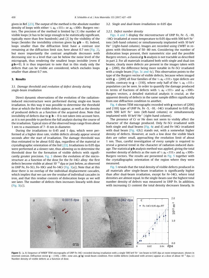
During the irradiations to 0.45 and 1 dpa, which were per-formed at a higher dose rate, visible defects already appear severalseconds after the start of irradiation. The damage threshold wasthus estimated to be about 0.02 dpa, regardless of the material orcrystallographic orientation of the foil [23]. Irradiations to 0.05 dpawere performed at a slower rate, thus allowing us to determine thethreshold dose for the formation of visible defects with signifi-cantly greater precision. Fig. 3 shows the evolution of the micro-structure as a function of the dose for the Fe-14Cr alloy: the firstdefects become visible at about 10�3 dpa or just below, as observedin UHP Fe, Fe-5Cr, Fe-10Cr and Fe-14Cr (Fig. 3(a)). Note that at thisdose there is no overlap of the individual displacement cascades,which implies that we can see the residue of individual cascades iniron, and that this residue consists of dislocation loops as we willsee later. The number of defects then increases linearly with dose(Fig. 3(c)).
0.0015 dpaa b
Figure 3. (a, b) Sequence of WBDF TEM micrographs of UHP Fe-14Cr recorded during irradinverted contrast. Diffraction vector g ¼ {110}, <100> zone axis, g(5g) weak-beam conditioNumber density of visible defects as a function of dose.
3.2. Single and dual-beam irradiations to 0.05 dpa
3.2.1. Defect number densityFigs. 4 and 5 display the microstructure of UHP Fe, Fe -5, -10,
-14Cr irradiated at room temperature to 0.05 dpa with 500 keV Feþ
ions (left-hand column) or simultaneously implanted with 10 keVHeþ (right-hand column). Images are recorded using CWBT in re-gions with thicknesses of 50e80 nm. Considering the number ofdislocation loops present, their nanometric size and the possibleBurgers vectors, a classical g$b analysis is not tractable as describedin part 2. For all materials irradiated both with single and dual-ionbeams, clearly more defects are present in the images taken withg ¼ {200}, the difference being more notable in Fe-5Cr irradiatedwith a single beam (Figs. 3c and 4c). This observation points to thetype of the Burgers vector of visible defects, because when imagedwith g ¼ {200} all four families of the ½ a0 <111> type defects arevisible, contrary to g ¼ {110}, where only half of the ½ a0 <111>population can be seen. In order to quantify the damage producedin terms of fractions of defects with ½ a0 <111> and a0 <100>Burgers vectors, a detailed statistical analysis is crucial, as theapparent density of defects in the same sample differs significantlyfrom one diffraction condition to another.
Fig. 4 shows TEM micrographs recorded with g vectors of {200}and {110} type of UHP Fe, Fe -5, -10, -14Cr irradiated to 0.05 dpawith 500 keV Feþ ions (left-hand column) or simultaneouslyimplanted with 10 keV Heþ (right-hand column).
The presence of Cr or He does not seem to visibly affect thecharacter of the damage produced. Only Fe-5Cr irradiated withboth single and dual beams (Fig. 4c and d) and Fe-14Cr irradiatedwith dual beam (Fig. 4(h)) stands out, with a somewhat higherdensity of defects. However, at such a low dose the visible blackdots are rather small, approaching the resolution limit of about1 nm. Thus, careful investigation of every sample is required toreveal a general trend in the character of radiation-induced dam-age. The statistical g·b analysis methodwas applied, giving the totalnumber density of defects as the sum of ½ a0 <111> and a0 <100>Burgers vectors. The results are presented in Fig. 5 together withthe crystallographic orientation of the region where they weremeasured.
Fig. 5 reveals that the total density of visible defects produced inall materials after single-beam irradiation is significantly higherthan after dual-beam irradiation, except for Fe-14Cr, where totaldensities are almost equal. In the single-beam case the highest totalnumber density of defects was measured in UHP Fe. In addition,with increasing Cr content the total density decreases linearly. In
0.042 dpa c 2.0
0.0
1.0
dpa
2.0
1022 m-3
iation with a single 500 keV Feþ ion beam to 0.05 dpa at room temperature, shown inn. First visible defects (indicated with arrows) appear at a dose of about 10�3 dpa. (c)

1 dpa 1 dpa+1000 appm He 1 dpa 1 dpa+1000 appm HeUHPFe
Fe-5CrFe=10C
rFe-14C
r
Figure 4. Sample of (a) UHP Fe, 70 nm thick; (c) Fe-5Cr, 70 nm thick; (e) Fe-10Cr, 55 nm thick; (g) Fe-14Cr, 70 nm thick, irradiated to 0.05 dpa at RT with 500 keV Feþ. Sample of (b)UHP Fe, 80 nm thick; (d) Fe-5Cr, 80 nm thick; (f) Fe-10Cr, 80 nm thick; (h) Fe-14Cr, 70 nm thick, irradiated at RT to 1 dpa with 500 keV Feþ and implanted with 1000 appm He using10 keV Heþ. CWBT, g ¼ {200}, g(3g) and g ¼ {110}, g(4g) condition, 200 kV. Micrographs are shown in inverted contrast.
R. Sch€aublin et al. / Acta Materialia 133 (2017) 427e439 431
more detail, the total density of visible defects decreases from10.6 ± 1.4� 1022 m�3 for UHP Fe to 4.7 ± 1.4� 1022 m�3 for Fe-14Cr.In Fe-10Cr irradiated in single-beam condition, several grains wereavailable for investigations, among them [111] and [011] grains, andtwo grains with orientations between [011] and [001].
After dual-beam irradiation, of all materials UHP Fe shows thelowest total number density of visible defects, contrary to thesingle-beam case. Among the Fe(Cr) alloys the highest total densityis measured for Fe-5Cr, while for Fe-10Cr the total density drops,though still exceeding that of UHP Fe. For Fe-14Cr it increases again.It thus appears that for Fe(Cr) alloys a minimum total defect densityis observed for Fe-10Cr.
3.2.2. Defect sizeFig. 6 shows the size distributions of visible defects produced in
the materials investigated under both single 500 keV Feþ and dual500 keV Feþ, 10 keV Heþ beam irradiations to the dose of 0.05 dpaand 50 appm He content.
In the Fe(Cr) alloys the diameter of almost all defects is between0.5 and 1 nm; only a few loops larger than 2 nm are observed. Theaverage size of visible defects does not depend on the Cr content orHe presence. It is estimated to be 1.1 nm for all Fe(Cr) materialsexcept for Fe-10Cr irradiated with dual beam, where themajority ofdefects are generally smaller, below 1 nm in diameter, with anaverage size of 0.9 nm. The sizes of defects produced in UHP Fe areslightly larger than in Fe(Cr): most are between 1 and 2 nm.However, again, the presence of He does not affect the size distri-bution; the average size of the defects after both single and dual-beam irradiations is about 1.4 nm.
3.2.3. Defect Burgers vectorThe Burgers vector of the small dislocation loops was deter-
mined using the statistical method. It is assumed that the loopshave a Burgers vector that is either ½ a0 <111> or a0 <100>. Theresulting number densities of defects with ½ a0 <111> and a0<100> Burgers vectors produced after the irradiation with single
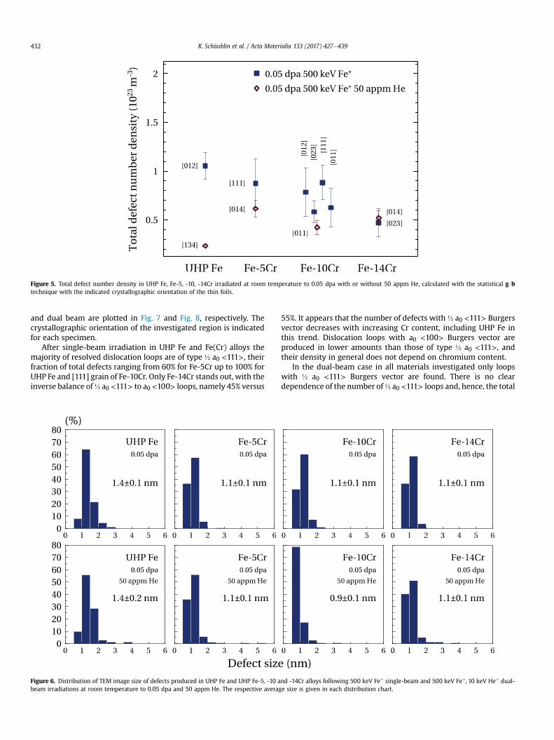
Figure 5. Total defect number density in UHP Fe, Fe-5, -10, -14Cr irradiated at room temperature to 0.05 dpa with or without 50 appm He, calculated with the statistical g$btechnique with the indicated crystallographic orientation of the thin foils.
R. Sch€aublin et al. / Acta Materialia 133 (2017) 427e439432
and dual beam are plotted in Fig. 7 and Fig. 8, respectively. Thecrystallographic orientation of the investigated region is indicatedfor each specimen.
After single-beam irradiation in UHP Fe and Fe(Cr) alloys themajority of resolved dislocation loops are of type ½ a0 <111>, theirfraction of total defects ranging from 60% for Fe-5Cr up to 100% forUHP Fe and [111] grain of Fe-10Cr. Only Fe-14Cr stands out, with theinverse balance of½ a0 <111> to a0 <100> loops, namely 45% versus
Figure 6. Distribution of TEM image size of defects produced in UHP Fe and UHP Fe-5, -10 abeam irradiations at room temperature to 0.05 dpa and 50 appm He. The respective avera
55%. It appears that the number of defects with ½ a0 <111> Burgersvector decreases with increasing Cr content, including UHP Fe inthis trend. Dislocation loops with a0 <100> Burgers vector areproduced in lower amounts than those of type ½ a0 <111>, andtheir density in general does not depend on chromium content.
In the dual-beam case in all materials investigated only loopswith ½ a0 <111> Burgers vector are found. There is no cleardependence of the number of½ a0 <111> loops and, hence, the total
nd -14Cr alloys following 500 keV Feþ single-beam and 500 keV Feþ, 10 keV Heþ dual-ge size is given in each distribution chart.

Figure 7. Density of defects with ½ a0 <111> and a0 <100> Burgers vectors in samplesirradiated with single 500 keV Feþ ion beam to the dose of 0.05 dpa at RT. The foilnormal is indicated for each region investigated. The error bar for values zero is a few1021 m�3 and hidden by the data symbol.
R. Sch€aublin et al. / Acta Materialia 133 (2017) 427e439 433
number density of visible defects on the chromium content. Thelowest density of defects is observed for UHP Fe, with Fe(Cr) alloysshowing significantly a higher number density. Among Fe(Cr) ma-terials, Fe-10Cr has a slightly lower defect density than Fe-5Cr andFe-14Cr.
3.3. Effects of dose rate in UHP Fe
In order to investigate the effects of the dose rate of theincoming ions on the character of damage produced in single anddual-beam cases, UHP Fe was irradiated at three dose rates at roomtemperature with 500 keV Feþ ions to 1 dpa with and without1000 appm of He implanted as 10 keV ions. High dose-rate singleand dual-beam irradiations lasted 0.5 h at a rate of damage pro-duction of 5.5 � 10�4 dpa s�1 and 0.55 appm s�1 for the rate of Heimplantation. Low dose-rate irradiations were ten times slower,lasting 5 h, with corresponding irradiation/implantation rates of5.5 � 10�5 dpa s�1 and 0.055 appm s�1 for Fe and He ions,
Figure 8. Density of defects with ½ a0 <111> and a0 <100> Burgers vectors in samplesirradiated with dual 500 keV Feþ and 10 keV Heþ ion beam to the dose of 0.05 dpa and50 appm He content at RT. The foil normal is indicated for each region investigated.The error bar for values zero is a few 1021 m�3 and hidden by the data symbol.
respectively. Another set of irradiations was performed at a rate of2.8 � 10�4 dpa s�1 and 0.28 appm s�1 for Fe and He ions, respec-tively, which is two times slower than for the highest dose-rateirradiations.
In the single-beam case direct observations of the defect evo-lution under irradiation were performed for the 5.5 � 10�4 dpa s�1
and 5.5 � 10�5 dpa s�1 dose rates. The density and size of defectsare retrieved from the images recorded during irradiation. Fig. 9presents the evolution of the density of visible defects with dosefor different dose rates.
It appears that the number density of defects does not dependon the dose rate. For both the highest and lowest dose rate, densitygrows linearly up to about 0.3 dpa, beyond which saturation isreached. As for the average size, larger defects are clearly observedin the case of the lowest dose rate. For both dose rates defect size isgenerally not dependent on the dose; only slightly smaller defectsare observed at the beginning of the irradiations, which impliesthat the average defect size follows the same trend as density,reaching saturation at about 0.3 dpa.
Irradiated thin foils were investigated post mortem. Resultsobtained using statistical Burgers vector analysis are presented inFig. 10(a) and (b) with respect to dose and He implantation rate fordual-beam cases. The total density of visible defects is shown inFig. 11. For the sake of clarity dose rate is plotted on a logarithmicscale.
Fig. 10(a) shows that after single-beam irradiation the density ofboth a0 <100> and ½ a0 <111> type defects is not affected by thedose rate. In general, loops with ½ a0 <111> Burgers vector arefound in slightly lower numbers than those with a0 <100>. In moredetail, the ratio of ½ a0 <111> loops to a0 <100> loops is estimatedto be between 30 and 45% regardless of the dose rate, with only oneexception, where it is more than 60%. However, it appears that thedose rate has a notable effect on the types of loop observed afterdual-beam irradiation.
As shown in Fig. 10(b), at the highest dose rate the defect pop-ulation is dominated by ½ a0 <111> loops, 100% of visible defectsbeing of this type. For the medium dose rate a relatively smallnumber of a0 <100> loops, about 15% of total population, isobserved, and for the lowest dose rate the density of a0 <100> and½ a0 <111> loops is similar. To sum up, the total density of visibledefects in the single-beam case does not depend significantly onthe dose rate. After dual-beam irradiation at the lowest dose thereis a slight decrease in the total density of defects compared to thetwo highest dose rates, at which the total densities are identical,indicating a possible saturation of the dose-rate effect on thenumber density.
For thin foils irradiated with single and dual beam at the highestdose rate enough data were obtained to perform an extended sta-tistical g$b analysis and thus distinguish between the dislocationloops belonging to four different families within the ½ a0 <111>type Burgers vector: ½ a0 ½111�; ½ a0 ½111�; ½ a0 ½111� and ½ a0½111�. It appears that in UHP Fe irradiated in single beam at highdose rate, 5.5� 10�4 dpa s�1, the proportion of families of type ½ a0<111> defects are distributed according to their orientation to-wards the free surface. The vector normal to the investigated grainin this case is [225]. In more detail, defects with Burgers vector½ a0[111] and½ a0 ½111� oriented at 19� and 51� towards the foil normalare not present at all and the sum of ½ a0 ½111� and ½ a0 ½111� de-fects, which are oriented almost parallel to the surface of thesample, constitute the full 111 loop population.
Conversely, in UHP Fe irradiated at the same dose rate in pres-ence of He, the ½ a0 <111> families are equalized in the foil, sup-porting the idea that He stabilizes mobile ½ a0 <111> loops. So,among a total of 100% of ½ a0 <111> loops 22 ± 14% are ½ a0 [111],52 ± 9% are ½ a0 ½111� and ½ a0 ½111� together and, finally, 26 ± 13%

Figure 9. Evolution with dose of (a) the number density of visible defects and (b) the average defect size in UHP Fe irradiated to 1 dpa at 5.5 � 10�4 dpa s�1 and 5.5 � 10�5 dpa s�1
dose rates. Results are obtained from the TEM images recorded during irradiation with a diffraction vector g ¼ {110}, g(5g) weak-beam condition. Density is not corrected forinvisibilities due to g$b ¼ 0.
Figure 10. Density of defects with a0 <100> and ½ a0 <111> Burgers vectors in UHP Fe irradiated at RT with (a) single 500 keV Feþ ion beam at 5.5 � 10�5 dpa s�1, 2.8 � 10�4 dpa s�1
and 5.5 � 10�4 dpa s�1 and (b) dual 500 keV Feþ and 10 keV Heþ ion beams with 0.55, 0.28 and 0.055 appm s�1 He implantation, respectively. The foil normal is indicated for eachregion investigated.
R. Sch€aublin et al. / Acta Materialia 133 (2017) 427e439434
belong to the ½ a0 ½111� family. Normal to the foil in this case is[115], hence, the orientations of the families to it are 27�, 85�, 85�
and 43�, respectively.
3.4. Effects of the irradiation temperature in UHP Fe
Irradiation at liquid nitrogen temperature allows studying theirradiation-induced microstructure with a reduced effect of ther-mal evolution, thus maximizing the chances of observing defectsstemming directly from the displacement cascades. UHP Fe wasirradiated with a single 500 keV Fe þ ion beam to 1 dpa at 93 K, at adose rate of 5.5 � 10�4 dpa s�1. The irradiated thin foil was tilted toachieve several diffraction conditions in order to determine theBurgers vectors of the visible defects. The sample was thenwarmedto room temperature and transported to PSI Villigen, where theinvestigated region was traced back and analyzed in TEM.
Fig. 12a and b shows TEM pictures of approximately the sameregion of the irradiated sample recorded at low temperature and
after warming to room temperature. Images were taken with a g ¼(011) diffraction vector close to the [011] zone axis. The thickness ofthe regions was about the same: 100 nm measured from thenumber of thickness fringes for Fig. 12(a), and 130 nm measuredfrom the EELS spectrum for Fig. 12(b). It is seen that the density ofvisible defects is higher at low temperature, which appears logical,as the mobility of the defects is reduced and, hence, fewer defectsare being eliminated to free surfaces or by annihilation. Detailedstatistical Burgers vector analysis reveals that the total density ofdefects produced drops from 9.8 (±0.1) � 1022 m�3 at 93 K to5.8 (±0.5) � 1022 m�3 at room temperature. The decrease happensat the expense of ½ a0 <111> loops, whose absolute density di-minishesmore than two-fold after warming, while the density of a0<100> loops remains approximately the same: 2.6 (±0.1) � 1022
m�3 and 3.0 (±0.4) � 1022 m�3 for 93 K and room temperature,respectively. In thinner areas loss of ½ a0 <111> loops afterwarming to room temperature is evenmore pronounced. Indeed, inthe 60 nm thick region, located near the previous ones, the density
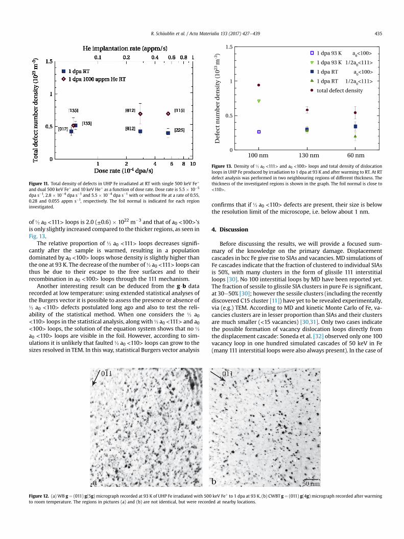
Figure 13. Density of ½ a0 <111> and a0 <100> loops and total density of dislocationloops in UHP Fe produced by irradiation to 1 dpa at 93 K and after warming to RT. At RTdefect analysis was performed in two neighbouring regions of different thickness. Thethickness of the investigated regions is shown in the graph. The foil normal is close to<110>.
Figure 11. Total density of defects in UHP Fe irradiated at RT with single 500 keV Feþ
and dual 500 keV Feþ and 10 keV Heþ as a function of dose rate. Dose rate is 5.5 � 10�5
dpa s�1, 2.8 � 10�4 dpa s�1 and 5.5 � 10�4 dpa s�1 with or without He at a rate of 0.55,0.28 and 0.055 appm s�1, respectively. The foil normal is indicated for each regioninvestigated.
R. Sch€aublin et al. / Acta Materialia 133 (2017) 427e439 435
of ½ a0 <111> loops is 2.0 (±0.6) � 1022 m�3 and that of a0 <100>’sis only slightly increased compared to the thicker regions, as seen inFig. 13.
The relative proportion of ½ a0 <111> loops decreases signifi-cantly after the sample is warmed, resulting in a populationdominated by a0 <100> loops whose density is slightly higher thanthe one at 93 K. The decrease of the number of½ a0 <111> loops canthus be due to their escape to the free surfaces and to theirrecombination in a0 <100> loops through the 111 mechanism.
Another interesting result can be deduced from the g$b datarecorded at low temperature: using extended statistical analyses ofthe Burgers vector it is possible to assess the presence or absence of½ a0 <110> defects postulated long ago and also to test the reli-ability of the statistical method. When one considers the ½ a0<110> loops in the statistical analysis, along with½ a0 <111> and a0<100> loops, the solution of the equation system shows that no ½a0 <110> loops are visible in the foil. However, according to sim-ulations it is unlikely that faulted ½ a0 <110> loops can grow to thesizes resolved in TEM. In this way, statistical Burgers vector analysis
Figure 12. (a) WB g ¼ (011) g(5g) micrograph recorded at 93 K of UHP Fe irradiated with 500to room temperature. The regions in pictures (a) and (b) are not identical, but were record
confirms that if ½ a0 <110> defects are present, their size is belowthe resolution limit of the microscope, i.e. below about 1 nm.
4. Discussion
Before discussing the results, we will provide a focused sum-mary of the knowledge on the primary damage. Displacementcascades in bcc Fe give rise to SIAs and vacancies. MD simulations ofFe cascades indicate that the fraction of clustered to individual SIAsis 50%, with many clusters in the form of glissile 111 interstitialloops [30]. No 100 interstitial loops by MD have been reported yet.The fraction of sessile to glissile SIA clusters in pure Fe is significant,at 30e50% [30]; however the sessile clusters (including the recentlydiscovered C15 cluster [11]) have yet to be revealed experimentally,via (e.g.) TEM. According to MD and kinetic Monte Carlo of Fe, va-cancies clusters are in lesser proportion than SIAs and their clustersare much smaller (<15 vacancies) [30,31]. Only two cases indicatethe possible formation of vacancy dislocation loops directly fromthe displacement cascade: Soneda et al. [32] observed only one 100vacancy loop in one hundred simulated cascades of 50 keV in Fe(many 111 interstitial loops were also always present). In the case of
keV Feþ to 1 dpa at 93 K, (b) CWBT g ¼ (011) g(4g) micrograph recorded after warminged at nearby locations.
R. Sch€aublin et al. / Acta Materialia 133 (2017) 427e439436
near-surface displacement cascades in Fe, recent simulations bydifferent groups yielded various 100 vacancy loops and few 111ones [33,34], revealing the strong impact of a free surface on thedamage produced when located within about 10 nm from it. Thisis confirmed by experimental results in Fe [28]. It should be notedthat MD simulation of the formation energy of various vacancycluster configurations in Fe as a function of size indicates that thevoid is the most favourable one [35]. In sum, vacancies in bulk Fe(i.e. away from a free surface) either remain unclustered orcluster in sub-nanometric voids; it thus seems reasonable toconsider in the following discussion that loops are interstitial innature.
In Ref. [23] we saw that in pure Fe irradiated at RT with only Feions at 0.45 and 1 dpa there is a majority of 100 loops, and few111 ones. This is also reported in Refs. [28,36] for a similar dose(1.6 dpa) at RT and 300 �C. These authors [28,37] noted that thedefects density strongly depends on the crystal orientation, with acomplete loss of defects in pure Fe for a <111> foil normal. Thiscan be explained by the impact of the free surfaces, which in-creases with decreasing sample thickness, accompanied by astronger dependence on the crystal orientation as mentioned inpart 2. We have not observed such a dependence on crystalorientation in our study and in Ref. [23], presumably because ourthicknesses (>50 nm) are larger than the one they used (around30 nm), thus preventing a too strong effect of the free surfaces. Athigher doses (6.5e10 dpa) at RT and in thicker areas (>60 nm)these authors report, in Ref. [20], the formation of strings of 111loops. We note that this indicates that the spontaneous trans-formation from 111 loops to 100 loops as proposed in Ref. [38] isnot occurring in this case. This can be due to the blocking of the111 loops in the strings, frustrating the 111 mechanism. Fromthese findings it was concluded that 111 loops constitute theprimary damage, as also indicated by MD simulations [30], andthat 100 loops come mainly from the interaction of the mobile 111loops [23], according to the reaction ½ a0 [111] þ ½ a0 ½1�1�1� / a0[100]. This ‘111 mechanism’ was first deduced from experimentalobservations in 1965 [15] and later explored by MD simulations[39], where a completed reaction was reported only recently [40].We saw that in the presence of He the ratio of the 111 to 100 loopswas reversed [23]. MD simulations indicate that He segregates tothe 111 loops [41,42], and He stabilizes vacancy clusters (even-tually forming He bubbles) [43,44]. Both mechanisms mayimpede 111 loops mobility, thus reducing their mutual interac-tion, which in turn frustates the formation of 100s. Note that thesame idea was put forward recently to explain the higher numberdensity and size of 100 loops in 500 �C dual-beam ion irradiationof the same materials [18]. According to this view the 111 loopsthus dominate the microstructure in the presence of He. A similartrend was observed with Cr in single-beam irradiations [23]: in itspresence the majority of the loops are 111, contrary to pure Fe. Itwas concluded that Cr in Fe also impedes the mobility of 111s[23]. MD simulation results confirm this behaviour for both smallSIA clusters [45] and 111 loops [46]; it is due to Cr segregation tothe loops [46]. In the presence of He and Cr the situation was lessclear, but the expected result would be that with the two ele-ments impeding the 111 motion much fewer 100 loops would beobserved, which was not the case: there were still more 100 loopsthan in the case of pure Fe with He [23]. A synergistic effect of Heand Cr was proposed. We will see in the following that the pre-sent results confirm that, firstly, the 111s constitute the primaryloop population, and, secondly, that Cr actually favours the for-mation of 100 loops, irrespective of the fact that it may or may notinfluence the mobility of 111 loops.
The present experiment at the low dose of 0.05 dpa allowed us
to explore themicrostructure evolutionwhen time is short (relativeto the previous irradiation at 0.5 to 1 dpa reported in Ref. [23]) andthus to see what happens at the beginning of the irradiation-induced microstructure evolution. At this dose in pure Fe only 111loops are visible, and no 100 loops (Fig. 7). In view of the 111mechanism, the lack of 100s at 0.05 dpa may thus originate in thelack of interaction between 111s, because of (1) their much lowernumber density due to the dose (10 times lower) and (2) thereduced available time for their interaction because of the shorterirradiation. Their integrity is thus preserved and they dominate themicrostructure. Thanks to the short available time the effect of theincorporation of He is now even clearer; in this case no 100 loopsare visible, which confirms that (1) primary loops are 111s and that(2) their mobility is limited by He. Only their visible density isaffected, with an apparent reduction, because the decrease in theirdiffusity due to He impedes their growth and thus their visualiza-tion in the TEM. When enough time is given (as reported inRef. [23]) 111 loops can movemore and thus interact to result in theformation of 100s. At low doses, in the case of the material con-taining Cr and in the single-beam case, curiously, while themajorityof the loops are 111,many100s are visible. It thus appears that at lowdose and in the single-beam case, Cr actually favours the formationof100 loops (seeFig. 7of this paper), as theyarenotvisible inpureFe.In addition, dual-beam results confirm that the presence of He re-duces themobility of 111 because the formation of 100 is completelyrestricted in all cases, irrespective of the Cr content (Fig. 8).
At high dose [23], or when more time is for the 111 loopdiffusion to occur, one expects to see more 100 loops due to theirfacilitated interaction. This is clearly so in the single-beam case inpure Fe (Fig. 11 in Ref. [23]), with the 100 character dominating theloop population. In Fe(Cr), one sees some 100 loops, but the 111sstill constitute the majority, confirming the idea that Cr can impedethe mobility of 111s [23]. In the dual-beam case, the presence of Hehinders the formation of 100 loops because He impedes themovement of 111 loops. This is clearly seen in pure Fe, but with Cr itappears that 100 loops still form, and in quantities slightly largerthan in pure Fe (Fig. 12 in Ref. [23]). In presence of Cr, He thus seemsto be less capable of impeding the formation of 100s if enough timeis given, which strengthens the intriguing idea that Cr actuallyfavours the formation of 100 loops. This could be due to severalatomistic mechanisms, of which three seem to fit the present re-sults. Let us first consider the cases without He, where 100 loops areobserved in presence of Cr.
(1) Theremay be a catalytic effectwhereby the Cr atoms are thelocations where the 111 loops experience a spontaneous re-action and transform to 100. This was proposed by Arakawa(but in pure Fe) on the basis of experimental observations[38]. This catalytic effect may also reveal itself in the result ofthe reaction between 111 loops, whereby 100 loops would bepromoted by the presence of Cr; however, recent MD simu-lations [47] indicate that the impact of Cr on such a reactionis low, and if anything would cause the opposite effect andactually promote 111 loops.
(2) There may be an acceleration effect whereby Cr wouldactually favour the diffusion of the 111 loops, which in turnwould favour the formation of the 100 loops. An acceleratingeffect was revealed by MD simulation in Fe(Cr) for the singleSIAs mobility. It is increased in the presence of Cr, but only attemperatures below about 400 K; at higher temperature Crreduces SIA diffusion [48]. However, the mobility of the SIAclusters in MD simulations appears to be consistentlyreduced by the presence of Cr, with a minimum at 10% Cr forsmall clusters. It shifts towards lower concentrations with

R. Sch€aublin et al. / Acta Materialia 133 (2017) 427e439 437
increasing cluster size [49]. To sum up, MD simulations donot support an acceleration effect on the mobility of SIAclusters due to Cr.
(3) There may be a bias effect, whereby due to the presence ofCr in the damage left by the displacement cascade aftercooling, some 100 loops may form readily, in addition to the111 loops. However, MD simulations show that displacementcascades in pure Fe mainly generate 111 loops [50], no 100loops [51], and some 3D SIA sessile configurations [30]. Itshould be noted that the fraction of sessile to glissile SIAclusters in pure Fe is indeed significant, at 30e50% [30];however, these have not yet been revealed in TEM. Note alsothat the fraction of clustered SIAs is 50% [30]. In Fe(Cr) Ter-entyev et al. [52] found by MD simulations that Cr in Fe doesnot seem to affect the damage resulting from cascadessignificantly, at least in terms of point defects number den-sities and clusters densities and sizes (there was no indica-tion of the type of clusters). To sum up, at this point MDsimulations do not support the bias hypothesis of the directformation of 100s due to Cr in Fe displacement cascades.
In the presence of He the role of Cr is more complex. An MDstudy [53] showed that Cr reduces the mobility of He in Fe(Cr)relative to pure Fe, with consequently less He decorating the 111loops. In this view, Cr may mitigate the impact of He: in the pres-ence of Cr, the reduction in mobility of the 111 clusters by Hewouldbe less than in pure iron. This should in turn allow them to remainmobile and form 100 loops. This is the case for the high dose in thepresent study [23]. However, in the low-dose irradiation of thematerials containing Cr the contrary is observed; when He is pre-sent no 100 loops are present, challenging this idea, but it should benoted that the time may be too short for any mechanism involvingmobility to operate. There may be other synergistic effects betweenCr and He on the damage resulting from displacement cascades, asindicated by recent MD studies [54]: interstitial He could increasethe number of point defects. However at the content of interesthere, 1000 appm He, the impact of He is insignificant [54]. In pureFe we saw a similar situation, where He at these concentrations hasan insignificant impact on the resulting point defects number [42].To sum up, in MD simulations He has no effect on the formation ofdislocation loops in displacement cascades. We therefore concludethat He only affects the mobility of the 111s.
The dose rate has an impact on the resulting irradiation-induced microstructure. In UHP Fe in the single-beam case thedose rate does not significantly affect either the total numberdensity or the fraction of 111 to 100 loops. Conversely, in the dual-beam case and for the same dose the resulting number density ofdislocation loops increases with an increasing dose rate. The frac-tion of 111 to 100 loops also increases strongly with increasing doserate. These results can be analyzed in viewof the 111mechanism; inthe case of the single-beam irradiation the 111 loops move freelyand seem to have enough time to cover sufficient distances tointeract and form a significant fraction of 100 loops at any of thedose rates investigated. We have seen that in some cases the 100loops dominate the microstructure, with only few 111s. In the dual-beam case, however, i.e. in the presence of He, at the highest doserate the 111 loops impeded by He do not have enough time to moveand interact to form 100 loops, while at the lowest dose rate asignificant fraction of 100 loops are again formed, indicating thathere the 111 loops had time to move and interact. To sum up, thedose-rate experiment findings support the 111 mechanism.
The temperature also has a significant impact on the resultingmicrostructure, in particular on the fraction of 111 to 100 loops. Ineffect, at liquid nitrogen temperature in UHP Fe and upon single-beam irradiation the 111 loops dominate the microstructure over
the 100s. This indicates that the 111 loops are immobilized by thelow temperature. Upon heating to room temperature the ratio of111 to 100 loops reaches about 1 and the density of 100 loopsslightly increases. This indicates that the 111 loops have moved (1)to escape to the free surfaces and (2) to interact and form 100sbecause of the observed increase of their number density. In sum,the low-temperature experiment supports the idea that 111 loopsare the source of 100 loops.
In summary, it appears that 111 loops constitute the primaryloops and that the ‘111 mechanism’ for the 100 loop formationsatisfactorily explains the comparative results on the dislocationloop populations obtained at 1 dpa and at RT in single and dual-beam experiments in pure Fe and in Fe(Cr). The key mechanism isthe mobility of the 111 loops, which is reduced by He and Cr, amechanism that was also revealed in MD simulations for the latter;in turn it impedes the formation of the 100 loops. The ‘111 mech-anism’ also explains the observed dose-rate and temperature effect.However, at low doses (0.05 dpa), it appears that Cr favours theformation of 100 loops, irrespective of the analysis regarding themobility of the 111 loops. This contradicts the 111 mechanismsomewhat, because in this view Cr, reducing the mobility of 111s,should not favour 100 formation. One additional mechanism thatmight be put forward is a catalytic effect promoting the sponta-neous transformation of the 111 loops to 100 loops following Ara-kawa's suggestions [38]. However, our conclusions indicate that inthe case the primary 111 loops are blocked by He there are muchless 100 loops, in particular at low dose, which does not support theidea of the spontaneous transformation of 111s to 100s. Besides,there may be a spontaneous transformation to 100 loops of thesessile clusters (including the C15 clusters [11]), which according toMD simulations of displacement cascades in Fe represent a signif-icant fraction of the primary SIA clusters (30e50%) [30]. Moreover,predicting the evolution of the irradiation-induced microstructureby e.g. Monte Carlo numerical simulations is fairly successful only ifa good fraction of immobile defects is considered [9], which couldbe those sessile clusters. Effort should thus now be devoted to theexperimental investigation of the sessile clusters in irradiatedFe(Cr).
5. Conclusions
In this study thin foils of UHP Fe and Fe(Cr) alloys were irradi-ated in situ in a TEM via single-beam or dual-beam experimentsmainly at room temperature up to a dose of 1 dpawith 500 keV Feþ
and 10 keV He þ ions to investigate the origin of the self-interstitialatom dislocation loops. The temperature effect was investigatedusing single-beam irradiation of UHP Fe at liquid nitrogen tem-perature. The dose-rate effect was investigated at room tempera-ture via single and dual-beam irradiation of UHP Fe.We have testedthe idea that 100 loopsmay stem from the interaction of themobile111 loops according to the ‘111 mechanism’. From our findings weconclude the following:
1. The dose threshold to see defects in Fe(Cr) in TEM is about 10�3
dpa, which is before the overlap of displacement cascades. Thisindicates that dislocation loops can form directly in the collapseof displacement cascades.
2. 111 loops constitute the main primary dislocation loop popu-lation in all cases. They can lead to the formation of 100 loops viathe 111 mechanism.
3. At 0.5 and 1 dpa in pure Fe the loop population is dominated by100 loops, which can be explained with the 111 mechanism.
4. In the presence of He the loop population is dominated by 111loops, indicating that, according to the 111 mechanism, He im-pedes the movement of 111 loops.

R. Sch€aublin et al. / Acta Materialia 133 (2017) 427e439438
5. At 0.5 and 1 dpa in the presence of Cr there are fewer 100 loopsthan in pure Fe, indicating that according to the 111 mechanismCr also impedes 111 loop motion.
6. At 0.05 dpa in pure Fe the microstructure is dominated by 111loops. This may result from the fact that they have less time tomigrate and are less numerous, which frustrates the formationof 100 loops.
7. At 0.05 dpa in the presence of Cr there are more 100 loops thanin pure Fe. This indicates that Cr somehow favours the formationof 100 loops, irrespective of its impact on the mobility of 111loops.
8. Attention should be paid to sessile SIA clusters, including theC15, as they may transform to 100 loops.
Acknowledgments
This work was carried out within the framework of the Euro-pean Fusion Development Agreement, now EUROfusion, in theMAT-IREMEV project. The Swiss National Science Foundation isthanked for financial support with grants #200020-121877,#200020-140505 and #200021-172934. The authors alsoacknowledge the outstanding work of the JANNuS Orsay team andScopeM ETHZ for the overall use of its facility.
References
[1] J.L. Boutard, A. Alamo, R. Lindau, M. Rieth, Fissile core and Tritium-BreedingBlanket: structural materials and their requirements, C. R. Phys. 9 (3-4)(2008) 287e302.
[2] R. Schaublin, J. Henry, Y. Dai, Helium and point defect accumulation: (i)microstructure and mechanical behaviour, C. R. Phys. 9 (3-4) (2008) 389e400.
[3] Y. Serruys, P. Trocellier, S. Miro, E. Bordas, M.O. Ruault, O. Kaitasov, S. Henry,O. Leseigneur, T. Bonnaillie, S. Pellegrino, S. Vaubaillon, D. Uriot, JANNUS: amulti-irradiation platform for experimental validation at the scale of theatomistic modelling, J. Nucl. Mater. 386 (2009) 967e970.
[4] C. Domain, C.S. Becquart, Ab initio calculations of defects in Fe and dilute Fe-Cu alloys, Phys. Rev. B 65 (2) (2002) 024103.
[5] C.C. Fu, F. Willaime, P. Ordejon, Stability and mobility of mono- and di-interstitials in alpha-Fe, Phys. Rev. Lett. 92 (17) (2004) 175503.
[6] G. Wallner, H. Franz, R. Rauch, A. Schmalzbauer, J. Peisl, Diffuse X-ray scat-tering from defects after low temperature neutron irradiation, Mat. Sci. Forum15-18 (1987) 907e912.
[7] P. Ehrhart, Investigation of radiation-damage by X-ray-diffraction, J. Nucl.Mater. 216 (1994) 170e198.
[8] F. Willaime, C.C. Fu, M.C. Marinica, J. Dalla Torre, Stability and mobility of self-interstitials and small interstitial clusters in alpha-iron: ab initio and empiricalpotential calculations, Nucl. Instrum. Methods Phys. Res. Sect. B-BeamInteract. Mater. Atoms 228 (2005) 92e99.
[9] C.C. Fu, J. Dalla Torre, F. Willaime, J.L. Bocquet, A. Barbu, Multiscale modellingof defect kinetics in irradiated iron, Nat. Mater. 4 (1) (2005) 68e74.
[10] D.A. Terentyev, T.P.C. Klaver, P. Olsson, M.C. Marinica, F. Willaime, C. Domain,L. Malerba, Self-trapped interstitial-type defects in iron, Phys. Rev. Lett. 100(14) (2008) 145503.
[11] M.C. Marinica, F. Willaime, J.P. Crocombette, Irradiation-induced formation ofnanocrystallites with C15 laves phase structure in bcc iron, Phys. Rev. Lett.108 (2) (2012) 025501.
[12] A. Bourret, Irradiation damage in nickel and iron in a high-voltage electronmicroscope and threshold energy determination, Phys. Status Solidi A-Appl.Res. 4 (3) (1971) 813e825.
[13] S.L. Dudarev, R. Bullough, P.M. Derlet, Effect of the alpha-gamma phasetransition on the stability of dislocation loops in bcc iron, Phys. Rev. Lett. 100(13) (2008) 135503.
[14] B.C. Masters, Dislocation loops in irradiated iron, Nature 200 (490) (1963) 254.[15] B.C. Masters, Dislocation loops in irradiated iron, Phil. Mag. 11 (113) (1965)
881.[16] E.A. Little, B.L. Eyre, The geometry of dislocation loops generated in alpha-iron
by 1 MeV electron irradiation at 550�C, J. Microsc. 97 (1973) 107e111.[17] D. Brimbal, B. Decamps, A. Barbu, E. Meslin, J. Henry, Dual-beam irradiation of
alpha-iron: heterogeneous bubble formation on dislocation loops, J. Nucl.Mater. 418 (1-3) (2011) 313e315.
[18] D. Brimbal, B. Decamps, J. Henry, E. Meslin, A. Barbu, Single- and dual-beam insitu irradiations of high-purity iron in a transmission electron microscope:effects of heavy ion irradiation and helium injection, Acta Mater. 64 (2014)391e401.
[19] Z. Yao, M.L. Jenkins, M. Hernandez-Mayoral, M.A. Kirk, The temperaturedependence of heavy-ion damage in iron: a microstructural transition atelevated temperatures, Phil. Mag. 90 (35-36) (2010) 4623e4634.
[20] M. Hernandez-Mayoral, Z. Yao, M.L. Jenkins, M.A. Kirk, Heavy-ion irradiationsof Fe and Fe-Cr model alloys Part 2: damage evolution in thin-foils at higherdoses, Phil. Mag. 88 (21) (2008) 2881e2897.
[21] A.C. Nicol, M.L. Jenkins, M.A. Kirk, Matrix damage in iron, in: G.E. Lucas,L.L. Snead, M.A. Kirk, R.G. Elliman (Eds.), Materials Research Society Sympo-sium - Proceedings, 2001, pp. R1.3.1eR1.3.6.
[22] M.L. Jenkins, C.A. English, B.L. Eyre, Heavy-ion irradiation of alpha-iron, Phil.Mag. A 38 (1) (1978) 97e114.
[23] A. Prokhodtseva, B. Decamps, A. Ramar, R. Schaublin, Impact of He and Cr ondefect accumulation in ion-irradiated ultrahigh-purity Fe(Cr) alloys, ActaMater. 61 (18) (2013) 6958e6971.
[24] A. Prokhodtseva, Modelling Oriented Investigations of Primary RadiationDamage in Ultra High Purity Fe and Fe-cr Alloys (PhD thesis), EPFL, Lausanne,2013, p. 140.
[25] R. Schaublin, X. Meng, W.M. Stobbs, Weak beam under convergent beamillumination, Ultramicroscopy 83 (3-4) (2000) 145e157.
[26] R.F. Egerton, Electron Energy Loss Spectroscopy in the Electron Microscope,Plenum Press, 1996.
[27] W.W. Wu, R. Schaublin, J.C. Chen, General dislocation image stress of aniso-tropic cubic thin film, J. Appl. Phys. 112 (9) (2012) 093522.
[28] M.L. Jenkins, Z. Yao, M. Hernandez-Mayoral, M.A. Kirk, Dynamic observationsof heavy-ion damage in Fe and Fe-Cr alloys, J. Nucl. Mater. 389 (2) (2009)197e202.
[29] D.J. Cockayne, Principles and practice of weak-beam method of electron-mi-croscopy, J. Microscopy-Oxford 98 (JUL) (1973) 116e134.
[30] D.J. Bacon, F. Gao, Y.N. Osetsky, The primary damage state in fcc, bcc and hcpmetals as seen in molecular dynamics simulations, J. Nucl. Mater. 276 (2000)1e12.
[31] M.J. Caturla, N. Soneda, E. Alonso, B.D. Wirth, T.D. de la Rubia, J.M. Perlado,Comparative study of radiation damage accumulation in Cu and Fe, J. Nucl.Mater. 276 (2000) 13e21.
[32] N. Soneda, S. Ishino, T.D. de la Rubia, Vacancy loop formation by 'cascadecollapse' in alpha-Fe: a molecular dynamics study of 50 keV cascades, Phil.Mag. Lett. 81 (9) (2001) 649e659.
[33] M.J. Aliaga, R. Schaublin, J.F. Loffler, M.J. Caturla, Surface-induced vacancyloops and damage dispersion in irradiated Fe thin films, Acta Mater. 101(2015) 22e30.
[34] Y.N. Osetsky, A.F. Calder, R.E. Stoller, How do energetic ions damage metallicsurfaces? Curr. Opin. Solid St. M 19 (5) (2015) 277e286.
[35] M.R. Gilbert, Z. Yao, M.A. Kirk, M.L. Jenkins, S.L. Dudarev, Vacancy defects inFe: comparison between simulation and experiment, J. Nucl. Mater. 386-88(2009) 36e40.
[36] Z. Yao, M. Hernandez-Mayoral, M.L. Jenkins, M.A. Kirk, Heavy-ion irradiationsof Fe and Fe-Cr model alloys Part 1: damage evolution in thin-foils at lowerdoses, Phil. Mag. 88 (21) (2008) 2851e2880.
[37] M.A. Kirk, I.M. Robertson, M.L. Jenkins, C.A. English, T.J. Black, J.S. Vetrano, Thecollapse of defect cascades to dislocation loops, J. Nucl. Mater. 149 (1) (1987)21e28.
[38] K. Arakawa, M. Hatanaka, E. Kuramoto, K. Ono, H. Mori, Changes in the bur-gers vector of perfect dislocation loops without contact with the externaldislocations, Phys. Rev. Lett. 96 (12) (2006) 125506.
[39] J. Marian, B.D. Wirth, J.M. Perlado, Mechanism of formation and growth of <100 > interstitial loops in ferritic materials, Phys. Rev. Lett. 88 (25) (2002)255507.
[40] H.X. Xu, R.E. Stoller, Y.N. Osetsky, D. Terentyev, Solving the puzzle of < 100 >interstitial loop formation in bcc iron, Phys. Rev. Lett. 110 (26) (2013)265503.
[41] G. Lucas, R. Schaublin, Helium effects on displacement cascades in alpha-iron,J. Phys. Condens. Mat. 20 (41) (2008) 415206.
[42] J.N. Yu, G. Yu, Z.W. Yao, R. Schaublin, Synergistic effects of PKA and heliumon primary damage formation in Fe-0.1%He, J. Nucl. Mater. 367 (2007)462e467.
[43] K. Morishita, R. Sugano, B.D. Wirth, Thermal stability of helium-vacancyclusters and bubble formation - multiscale modeling approach for fusionmaterials development, Fusion Sci. Technol. 44 (2) (2003) 441e445.
[44] G. Lucas, R. Schaublin, Stability of helium bubbles in alpha-iron: a moleculardynamics study, J. Nucl. Mater. 386 (2009) 360e362.
[45] D. Terentyev, L. Malerba, A.V. Barashev, On the correlation between self-interstitial cluster diffusivity and irradiation-induced swelling in Fe-Cr al-loys, Phil. Mag. Lett. 85 (11) (2005) 587e594.
[46] D. Terentyev, F. Bergner, Y. Osetsky, Cr segregation on dislocation loops en-hances hardening in ferritic Fe-Cr alloys, Acta Mater. 61 (5) (2013)1444e1453.
[47] L.K. Beland, Y.N. Osetsky, R.E. Stoller, H.X. Xu, Interstitial loop transformationsin FeCr, J. Alloys Compd. 640 (2015) 219e225.
[48] D. Terentyev, P. Olsson, T.P.C. Klaver, L. Malerba, On the migration and trap-ping of single self-interstitial atoms in dilute and concentrated Fe-Cr alloys:atomistic study and comparison with resistivity recovery experiments, Comp.Mater. Sci. 43 (4) (2008) 1183e1192.
[49] D. Terentyev, L. Malerba, A.V. Barashev, Modelling the diffusion of self-interstitial atom clusters in Fe-Cr alloys, Phil. Mag. 88 (1) (2008) 21e29.
[50] R.E. Stoller, G.R. Odette, B.D. Wirth, Primary damage formation in bcc iron,J. Nucl. Mater. 251 (1997) 49e60.
[51] D.A. Terentyev, L. Malerba, M. Hou, Dimensionality of interstitial clustermotion in bcc-Fe, Phys. Rev. B 75 (10) (2007) 104108.
R. Sch€aublin et al. / Acta Materialia 133 (2017) 427e439 439
[52] D.A. Terentyev, L. Malerba, R. Chakarova, K. Nordlund, P. Olsson, M. Rieth,J. Wallenius, Displacement cascades in Fe-Cr: a molecular dynamics study,J. Nucl. Mater. 349 (1-2) (2006) 119e132.
[53] D. Terentyev, N. Juslin, K. Nordlund, N. Sandberg, Fast three dimensionalmigration of He clusters in bcc Fe and Fe-Cr alloys, J. Appl. Phys. 105 (10)
(2009) 103509.[54] N. Juslin, K. Nordlund, Molecular dynamics simulations of collision cascades in
FeCrHe, Nucl. Instrum. Methods Phys. Res. Sect. B-Beam Interact. Mater.Atoms 267 (20) (2009) 3420e3423.


![Study of interaction of Positronium with light atoms: H, He and Li - … · 2011. 9. 26. · H 2.126 a0 [1] 2.8 a0 He 1.566 a0 [1] 2.4 a0 Li 3.8-4.1 a0 [2] 5.8 a0* [1] Zhang et al.,](https://img.pdfslide.us/doc/110x75/60d6fc9e5d0bd91fec0eca5c/study-of-interaction-of-positronium-with-light-atoms-h-he-and-li-2011-9-26.jpg)