Embed Size (px)
Citation preview

P
Ofl
PZP
a
Cb
C
RA
I
Ts
t
h2(
erspectives in Science (2016) 7, 184—189
Available online at www.sciencedirect.com
ScienceDirect
j our na l homepage: www.elsev ier .com/pisc
n the instability of a modified cup-burnerame in the infrared spectral region�
etr Bitalaa,∗, Václav Nevrly a,b, Michal Strizíka, Eva Grigorováa,denek Zelingera,b, Pavel Kubáta,b, Pavel Kudrnaa,b,eter Piraa,b, Jan Wilda,b
Faculty of Safety Engineering, VSB — Technical University of Ostrava, Lumírova 13,Z-700 30 Ostrava 3 — Vyskovice, Czech RepublicInstitute of Thermomechanics, v.v.i., Academy of Sciences of the Czech Republic, Dolejskova 5,Z-182 00 Prague 8, Czech Republic
eceived 27 October 2015; accepted 20 November 2015vailable online 14 December 2015
KEYWORDSHydrodynamicinstability;Sooting flame;Cup-burnerapparatus;Infrared imaging
Summary This study describes the modification of a standardised cup-burner apparatus. Thereplacement of the original glass chimney is performed by shielding a nitrogen co-flow enabledmeasurement at a wavelength of 3.9 �m. This modification, together with a special arrangementof the measuring system (spectral filtering, data acquisition and post-processing), permittedthe observation of various types of hydrodynamic instabilities, including transition states. Theadvantages of our arrangement are demonstrated with an ethylene non-premixed flame withhigh sooting tendency. Two known modes of hydrodynamic instability (varicose and sinuous) thatoccur in buoyant flames were studied and described quantitatively. Based on the intensity of
the infrared emissions, we identified and qualitatively described the modes of periodic hydro-dynamic instability that are accompanied by flame tip opening, which has not been observedfor this type of flame.© 2015 Published by Elsevier GmbH. This is an open access article under the CC BY-NC-ND licenserg/l
l
(http://creativecommons.o
ntroduction
he authors of review (Steinhaus et al., 2007) clearlyhowed that despite the enormous body of work on
� This article is part of a special issue entitled ‘‘Proceedings ofhe 1st Czech-China Scientific Conference 2015’’.∗ Corresponding author.
whfp
ncm
ttp://dx.doi.org/10.1016/j.pisc.2015.11.030213-0209/© 2015 Published by Elsevier GmbH. This is anhttp://creativecommons.org/licenses/by-nc-nd/4.0/).
icenses/by-nc-nd/4.0/).
arge-scale pool fires there is a critical need for moreell instrumented experimental studies. Investigation of theydrocarbon flames in the laboratory scale is one of the keysor understanding to the hydrodynamics and heat transferrocesses involved in real industrial fires.
In order to analyse the instability modes of laminaron-premixed sooting flame we chosen a standardisedup-burner apparatus. It is frequently used as testing equip-ent to determine the minimal concentrations of gaseous
open access article under the CC BY-NC-ND license

Modified cup-burner flame 185
Nomenclature
SDmax maximum standard deviation (a.u.)Imax maximum soot radiation intensity (a.u.)HAB height above burner (m)Ri0 initial Richardson numbers
(= Dg/v20
), (—)
D diameter of fuel nozzle (m)g gravitational acceleration (m s−2)
(
Figure 1 Simplified scheme (cross-section) of the modifiedcup-burner apparatus. The green highlighting corresponds tothe additional nitrogen co-flow shroud. The red arrow designs afa
Tt
gmep
E
TfldM
Ieawl
v0 initial velocity of fuel (m s−1)
fire suppression agents (Senecal, 2005) or to investigateflame extinguishment processes (Katta et al., 2004, 2006;Takahashi et al., 2007; Linteris et al., 2007; Bitala et al.,2013). In addition to methods such as velocimetry and com-putational fluid dynamics (CFD), the flame of a cup-burnerhas been studied using narrow-band emission measurementsin the visible region (Takahashi et al., 2007). These measure-ments mainly yielded a spatially and temporally resolvedcharacterisation of a methane (CH4) flame with a relativelylow sooting tendency.
The infrared (IR) spectral region can be useful forthe diagnosis of highly sooting flames (e.g., Docquier andCandel, 2002). Currently, broad-band measurements havebeen used for this purpose (Hayasaka, 1996; Planas-Cuchiet al., 2003).
This work was performed to investigate the propertiesof a modified cup-burner system for monitoring spatiallyand temporally resolved radiative properties of an ethylene(C2H4) flame in a narrow-band for a wavelength of approxi-mately 3.9 �m. This wavelength was selected based on theintention to monitor the IR emissions of soot particles and tosimultaneously eliminate the irradiation of gas phase speciespresent in the flame. In addition, the special arrangementof the measuring system and the data evaluation procedurewere enabled to observe and describe various types of thehydrodynamic instabilities in the flame.
To measure the cup-burner flame in this spectral region,the original chimney was replaced by a shield co-flow sys-tem.
Experimental
Modification of the burner
The design of our apparatus was fundamentally based onstandards ISO 14520 (14520-1) and NFPA 2001. The mainmodifications were as follows (Fig. 1):
(a) The replacement of the original glass chimney by anouter co-flow shroud.
b) The modification of the diffuser.(c) The modification of the fuel nozzle.
Ad (a) The outer co-flow was used to ensure the trans-missivity of radiation in the middle IR region. Nitrogen wasused as the shielding gas and was fed into the co-flow shroud
through three horizontal inlets at angles of 120◦.Ad (b) In contrast to the system described in the standard,we added two inlets to supply the oxidiser (air), and the finalarrangement had a total of three inlets at angles of 120◦.
Tt3a
uel inlet, the blue arrow designs oxidiser inlet into the diffuser,nd the green arrow shows the nitrogen inlet.
his arrangement was used to increase the homogeneity ofhe oxidiser flow to ensure the axial symmetry of the flame.
Ad (c) The fuel nozzle cup was filled with a layer of 3 mmlass beads and was covered with two stainless steel wireeshes. This modification was similar to the work of Katta
t al. (2004, 2006), for obtaining a uniform inlet velocityrofile of the gaseous fuel.
xperimental setup
he experimental arrangement is depicted in Fig. 2. Theow rates of the gaseous fuel (C2H4 — 99.9% Linde Gas), oxi-iser (compressed air, SIAD) and co-flow nitrogen (99.999%,esser) were controlled by the Aalborg-type rotameters.
The spatially resolved emissions were monitored by anR camera (Electrophysics PV320L2ZE) that has a BST pyro-lectric focal plane array with a 240 × 320 pixels detectornd is covered with a ZnSe window. The measurementas performed using a 35 mm lens system with germanium
ens and integrated a manually adjustable iris diaphragm.
he spectral band-pass filter (Spectrogon BBP type) with aransmissivity of less than 5% at wavelengths outside the.75—4.02 �m range was placed between the camera lensnd the detector window.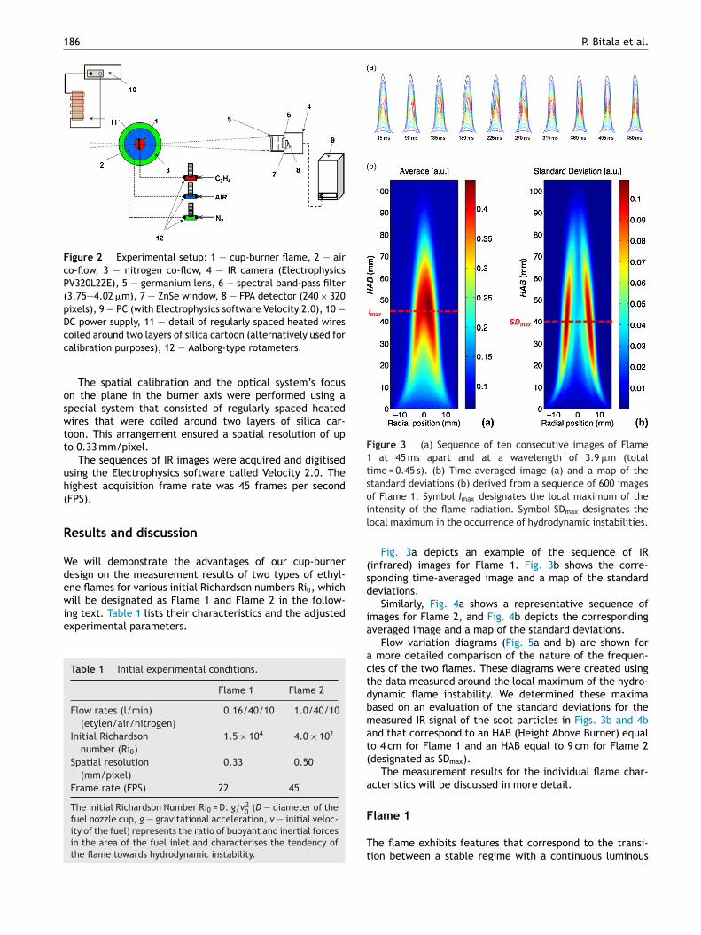
186 P. Bitala et al.
Figure 2 Experimental setup: 1 — cup-burner flame, 2 — airco-flow, 3 — nitrogen co-flow, 4 — IR camera (ElectrophysicsPV320L2ZE), 5 — germanium lens, 6 — spectral band-pass filter(3.75—4.02 �m), 7 — ZnSe window, 8 — FPA detector (240 × 320pixels), 9 — PC (with Electrophysics software Velocity 2.0), 10 —DC power supply, 11 — detail of regularly spaced heated wirescc
oswtt
uh(
R
Wdewie
Figure 3 (a) Sequence of ten consecutive images of Flame1 at 45 ms apart and at a wavelength of 3.9 �m (totaltime = 0.45 s). (b) Time-averaged image (a) and a map of thestandard deviations (b) derived from a sequence of 600 imagesof Flame 1. Symbol I designates the local maximum of theil
(sd
oiled around two layers of silica cartoon (alternatively used foralibration purposes), 12 — Aalborg-type rotameters.
The spatial calibration and the optical system’s focusn the plane in the burner axis were performed using apecial system that consisted of regularly spaced heatedires that were coiled around two layers of silica car-
oon. This arrangement ensured a spatial resolution of upo 0.33 mm/pixel.
The sequences of IR images were acquired and digitisedsing the Electrophysics software called Velocity 2.0. Theighest acquisition frame rate was 45 frames per secondFPS).
esults and discussion
e will demonstrate the advantages of our cup-burneresign on the measurement results of two types of ethyl-ne flames for various initial Richardson numbers Ri0, which
ill be designated as Flame 1 and Flame 2 in the follow-ng text. Table 1 lists their characteristics and the adjustedxperimental parameters.
Table 1 Initial experimental conditions.
Flame 1 Flame 2
Flow rates (l/min)(etylen/air/nitrogen)
0.16/40/10 1.0/40/10
Initial Richardsonnumber (Ri0)
1.5 × 10⁴ 4.0 × 10²
Spatial resolution(mm/pixel)
0.33 0.50
Frame rate (FPS) 22 45
The initial Richardson Number Ri0 = D. g/v20 (D — diameter of the
fuel nozzle cup, g — gravitational acceleration, v — initial veloc-ity of the fuel) represents the ratio of buoyant and inertial forcesin the area of the fuel inlet and characterises the tendency ofthe flame towards hydrodynamic instability.
ia
actdbmat(
a
F
Tt
max
ntensity of the flame radiation. Symbol SDmax designates theocal maximum in the occurrence of hydrodynamic instabilities.
Fig. 3a depicts an example of the sequence of IRinfrared) images for Flame 1. Fig. 3b shows the corre-ponding time-averaged image and a map of the standardeviations.
Similarly, Fig. 4a shows a representative sequence ofmages for Flame 2, and Fig. 4b depicts the correspondingveraged image and a map of the standard deviations.
Flow variation diagrams (Fig. 5a and b) are shown for more detailed comparison of the nature of the frequen-ies of the two flames. These diagrams were created usinghe data measured around the local maximum of the hydro-ynamic flame instability. We determined these maximaased on an evaluation of the standard deviations for theeasured IR signal of the soot particles in Figs. 3b and 4b
nd that correspond to an HAB (Height Above Burner) equalo 4 cm for Flame 1 and an HAB equal to 9 cm for Flame 2designated as SDmax).
The measurement results for the individual flame char-cteristics will be discussed in more detail.
lame 1
he flame exhibits features that correspond to the transi-ion between a stable regime with a continuous luminous

Modified cup-burner flame 187
Figure 4 (a) Sequence of 10 consecutive images of Flame 2 at22 ms apart and at a wavelength of 3.9 �m (total time = 0.22 s).The hydrodynamic instabilities of the varicose type predomi-nate in the first part of the sequence (a), a predominance of thesinuous instability mode in the second part of the sequence (b).(b) Time-averaged image (a) and a map of the standard devi-ations (b) derived from a sequence of 600 images of Flame 2.
Figure 5 (a) Flow variation diagram depicting a 4 s recordingof Flame 1 in a horizontal cross-section at a height of HAB = 4 cm.Time is depicted on the x-axis and the radial position on the y-axis. (b) Flow variation diagram depicting 4 s of the recording ofFTy
ttioEthtsr(
o(sflsF
icFomlapedo
Symbol Imax designates the local maximum of the intensity of theflame radiation. Symbol SDmax designates the local maximum forthe occurrence of hydrodynamic instabilities.
tip and the low-frequency pulsing mode of hydrodynamicinstabilities that accompany a periodic flame tip opening.
Fig. 3a depicts a representative sequence of infraredimages that show the progress of this phenomenon at 10different time intervals of approximately 45 ms and that cor-respond to the imaging frequency employed. A phase witha fully developed wing profile (with symmetrically locatedmaxima in the oxygenated region of the reaction zone) canbe clearly observed at the start and finish of the depictedsequence. The central part of the sequence is followed bythe stabilisation of the tip of the flame (i.e., a continuousarea of radiation with a local maximum close to the burneraxis).
The vertical profile of the radiation intensity on theflame axis becomes substantially deformed (becomes flat-ter) in the opening phase of the flame, where the change inthe flame height is not large (i.e., the total change equalsapproximately 5 mm). In the horizontal direction, the open-ing of the tip of the flame appears as a contraction and is
more visible in the flow variation diagram (see Fig. 5a andthe description in the text below).Additionally, the disturbance of the axial symmetry andthe systematic shift of the local maximum in the direction
oi
d
lame 2 in a horizontal cross-section at a height of HAB = 9 cm.ime is depicted on the x-axis and the radial position on the-axis.
owards the right-hand part of the flame can be observed inhe sequence of images. In addition, this deviation can bedentified in Fig. 3b(a), which depicts the spatial distributionf the temporally averaged intensity of the flame radiation.xpressed quantitatively, the relative difference betweenhe maximum radiation intensity (Imax) in the left and rightand parts of the flame corresponds to approximately 10% ofhe maximum signal intensity. Nonetheless, the map of thetandard deviations (Fig. 3b(b)) exhibits a nearly symmet-ical character, and the difference in the maximum valuesSDmax) between the right and left hand parts is less than 1%.
Fig. 3b(a) and (b) reveal a shift in the vertical positionf SDmax (HAB = 40 mm) compared with the position of ImaxHAB = 45 mm) in the direction upstream. This fact corre-ponds to the observed shift in the local maximum of theame radiation in the direction outside of the axis andimultaneously (downstream) to the edge of the burner (seeig. 3a).
The occurrence of the periodic local soot emission max-ma connected along with the axial symmetrical flameontraction can be observed in the flow variation diagram oflame 1 (Fig. 5a) at the height with the greatest occurrencef instability SDmax (HAB = 4 cm). In addition to random asym-etric fluctuations of the reaction zone, axially symmetrical
ow-frequency pulsations are observed with a frequency ofpproximately 3 Hz, and the flame tip opening occurs in thehase of minimum flame radial width. The widening of thexternal contours of the flame accompanied by a temporaryecrease in the radiation intensity, which is a consequencef a decrease in the local temperature or concentration
f the soot volume fraction, can be observed between thendividual phases of the contraction.We assume that the hydrodynamic instability of theescribed type is connected with the process of the radiative

1
hegtsbfop
ettfl
F
TFtst
ttsititTwt
eciss
trdoofla
oiboaattimfd
ititnCti
pRciulf
Hf1(itct1aswrrmhfl
wcma(
C
Fdssrooidtp
in
88
eat loss of the reaction zone through soot emission (Kattat al., 2009) and a change in the temperature and densityradient as a result of the relatively slow heat exchange inhe flame environment under these conditions. Another pos-ible explanation of the observed features of Flame 1 coulde a switch between the competitive mechanisms of sootormation (McEnally et al., 2006), such as the pure pyrolysisf C2H4 in the phase with a closed flame tip and the oxidativeyrolysis in the open flame phase.
This type of instability has not been described in the lit-rature. These types of instabilities differ substantially fromhe usual instabilities (e.g., of the varicose type not only inheir frequency but also in the other ‘‘fingerprints’’ in ourow variation diagrams).
lame 2
he frame rate was doubled for Flame 2 compared withlame 1 for the dynamics of the phenomena. Simultaneously,he monitoring region was broadened for this measuremento that the infrared images recorded the characteristic fea-ures of the flame for the hydrodynamic instabilities.
As observed in Fig. 4a, the flow is nearly stabilised athe flame base (HAB < 2 cm). Because of the forces of iner-ia at increased flow rates, this region does not exhibitubstantial indications of random fluctuations or systematicnstabilities. Further upstream (HAB > 5 cm) as the gravita-ional forces and thermal buoyancy begin to dominate, anncrease in the occurrence of vortex structures is observedhat causes an instability of the sinusoidal and varicose type.hese two modes intermingle. However, the ratio of time athich the flame exhibits a varicose character to the total
ime is approximately 10%.Based on the data depicted in Fig. 4b(a) and (b), a differ-
nce is observed for the relative positions of Imax and SDmax
ompared with Flame 1. The intensity of the soot radiationn Flame 2 reaches a maximum Imax at HAB = 7 cm, while thetandard deviation culminates at approximately 2 cm down-tream (SDmax at HAB = 9 cm).
From the shape of the flow variation diagram (Fig. 5b) inhe varicose regime, the phase of expansion with maximumadiation in the outer parts of the flame is followed by a sud-en narrowing of the external contours and a simultaneousccurrence of periodic local radiation minima in the areaf the burner axis. Thus, this behaviour is totally differentrom the horizontal expansion following the occurrence ofocal maxima of soot radiation for contraction instabilitiess observed in Flame 1.
Our measurements can be compared with the resultsbtained by other authors. The subject of hydrodynamicnstabilities in buoyant hydrocarbon flames was studied e.g.,y Cetegen and Dong (2000). In a propane flame, theybserved both varicose and sinusoidal oscillations and found
relationship between the probability of their occurrencend the value of the Richardson number. Compared withhese results, the features we observed in Flame 2 exhibithe characteristics of a transition regime between these
nstability modes. Nonetheless, the varicose regime occursore frequently in our experiments than the values providedor the relevant Richardson number in the cited work. Thisifference is most likely caused by co-flow (an air stream)
wwap
P. Bitala et al.
n our experimental arrangement, which could result inhe predominance of a symmetrical mode of hydrodynamicnstabilities. The opposite case occurs for Flame 1, wherehe occurrence of this mode of symmetrical instabilities wasot observed in the ethylene flame. In contrast, the work ofetegen and Dong mention a probability of occurrence forhe varicose regime in the propane flame at the correspond-ng Richardson number values of greater than 30%.
Boulanger (2010) proposed a specific mechanism thatrevents the occurrence of varicose structures at highichardson numbers. For the spatial distribution of the time-entred radiation intensities, the shape of Flame 1 observeds consistent with the predicted temperature profile of anltra-low Froude number flame for a vertical position of theocal maximum at a height of HAB = 1.8D (D is diameter ofuel nozzle cup).
At D = 28 mm, this height corresponds to approximatelyAB = 5 cm, which is consistent with the position of Imax
or Flame 1. Nonetheless, the dynamic character of Flame observed differs substantially from these predictionsBoulanger, 2010) because the given numerical simulations based on simplified assumptions for the prediction ofemperature and density gradients (single-step irreversiblehemistry). Thus, the absence of varicose structures andhe occurrence of a periodic opening of the tip for Flame
can be attributed to the chemical structure of ethylenes a fuel with a high sooting tendency. This is also con-istent with the conclusions of e.g., Kashir et al. (2012),ho observed reduced vorticities caused by additional heat
elease in propane nonpremixed flames compared to natu-al gas flames at same conditions. As demonstrated by theore detailed numerical simulation of Katta et al. (2009), a
igher soot concentration in the reaction zone stabilises theame through thermal radiation.
The unambiguous confirmation of the above hypothesisould require the application of an unsteady solver for theomputational fluid dynamics (CFD), including the imple-entation of a detailed scheme of the chemical kinetics
nd the thermal radiation model. The work of Cuoci et al.2013) is an example of this modelling method.
onclusions
or two burning regimes of a non-premixed flame, weemonstrated the advantages of the modification of atandard burner, which enabled a comparison of the emis-ions in the 3.9-�m spectral region. The spatial and temporalesolution of the experiment permitted monitoring of vari-us types of hydrodynamic instabilities. Two known modesf hydrodynamic instability occur in buoyant flames, includ-ng the transition states between them, were studied andescribed. Based on the intensity of the IR emissions ofhe soot, we qualitatively described an unknown mode oferiodic hydrodynamic instabilities.
The modification of the cup-burner apparatus, the exper-mental arrangement and the data processing provideew opportunities for investigating flames and other fuels
ith various sooting tendencies and for comparing themith model studies. The method described combined withdvanced post-processing methods permits a direct com-arison of the experimental data with the results of
K
K
K
K
L
M
P
S
S
Takahashi, F., Linteris, G.T., Katta, V.R., 2007. Extinguishment
Modified cup-burner flame
the comprehensive numerical simulations for physical andchemical processes in the flame environment similar toConnelly et al. (2009).
Conflict of interest
The authors declare that there is no conflict of interest.
References
Bitala, P., Kozubková, M., Kaderábek, P., Nevrly, V., Dlabka, J.,Kozubek, E., Stepánek, O., Bojko, M., Kubát, P., Zelinger, Z.,2013. Experimental investigations and numerical simulations ofmethane cup-burner flame. Eur. Phys. J. Web Conf. 45, 01067,http://dx.doi.org/10.1051/epjconf/20134501067.
Boulanger, J., 2010. Laminar round jet diffusion flame buoyantinstabilities: study on the disappearance of varicose structuresat ultra-low Froude number. Combust. Flame 157, 757—768,http://dx.doi.org/10.1016/j.combustflame.2009.12.005.
Cetegen, B.M., Dong, M.Y., 2000. Experiments on the instabil-ity modes of buoyant diffusion flames and effects of ambientatmosphere on the instabilities. Exp. Fluids 28, 546—558,http://dx.doi.org/10.1007/s003480050415.
Connelly, B.C., Bennett, B.A.V., Smooke, M.D., Long, M.B., 2009. Aparadigm shift in the interaction of experiments and computa-tions in combustion research. Proc. Combust. Inst. 32, 879—886,http://dx.doi.org/10.1016/j.proci.2008.05.066.
Cuoci, A., Frassoldati, A., Faravelli, T., Jin, H., Wang, Y., Zhang,K., Glaborg, P., Qi, F., 2013. Experimental and detailedkinetic modeling study of PAH formation in laminar co-flowmethane diffusion flames. Proc. Combust. Inst. 34, 1811—1818,http://dx.doi.org/10.1016/j.proci.2012.05.085.
Docquier, N., Candel, S., 2002. Combustion control and sen-sors: a review. Prog. Energy Combust. Sci. 28, 107—150,
http://dx.doi.org/10.1016/S0360-1285(01)00009-0.Hayasaka, H., 1996. Radiative characteristics and flame structureof small-pool flames. Fire Technol. 32, 308—322, http://dx.doi.org/10.1007/BF01037741.
189
ashir, B., Tabejamaat, S., Baig, M.M., 2012. An experimentalstudy of the stability of natural gas and propane turbulentnon-premixed flame under diluting condition. Therm. Sci. 16,1055—1065, http://dx.doi.org/10.2298/TSCI110617125K.
atta, V.R., Roquemore, W.M., Menon, A., Lee, S.-Y., Santoro, R.J.,Litzinger, T.A., 2009. Impact of soot on flame flicker. Proc.Combust. Inst. 32, 1343—1350, http://dx.doi.org/10.1016/j.proci.2008.06.152.
atta, V.R., Takahashi, F., Linteris, G.T., 2006. Fire-suppression characteristics of CF3H in a cup burner.Combust. Flame 144, 645—661, http://dx.doi.org/10.1016/j.combustflame.2005.09.006.
atta, V.R., Takahashi, F., Linteris, G.T., 2004. Suppressionof cup-burner flames using carbon dioxide in microgravity.Combust. Flame 137, 506—522, http://dx.doi.org/10.1016/j.combustflame.2004.01.015.
interis, G.T., Takahashi, F., Katta, V.R., 2007. Cup-burnerflame extinguishment by CF3Br and Br2. Combust. Flame149, 91—103, http://dx.doi.org/10.1016/j.combustflame.2006.12.013.
cEnally, C.S., Pfefferle, L.D., Atakan, B., Kohse-Höinghaus,K., 2006. Studies of aromatic hydrocarbon formation mecha-nisms in flames: progress towards closing the fuel gap. Prog.Energy Combust. 32, 247—294, http://dx.doi.org/10.1016/j.pecs.2005.11.003.
lanas-Cuchi, E., Chatris, J.M., López, C., Arnaldos, J., 2003.Determination of flame emissivity in hydrocarbon pool firesusing infrared thermography. Fire Technol. 39, 261—273,http://dx.doi.org/10.1023/A:1024193515227.
enecal, J.A., 2005. Flame extinguishing in the cup-burner by inertgases. Fire Saf. J. 40, 579—591, http://dx.doi.org/10.1016/j.firesaf.2005.05.008.
teinhaus, T., Welch, S., Carvel, R.O., Torero, J.L., 2007. Large-scale pool fires. Therm. Sci. 11, 101—118, http://dx.doi.org/10.2298/TSCI0702101S.
mechanisms of coflow diffusion flames in a cup-burner appa-ratus. Proc. Combust. Inst. 31, 2721—2729, http://dx.doi.org/10.1016/j.proci.2006.08.112.