Embed Size (px)
Citation preview

This is a repository copy of On the fundamental period of infilled RC frame buildings.
White Rose Research Online URL for this paper:http://eprints.whiterose.ac.uk/146297/
Version: Accepted Version
Article:
Asteris, PG, Repapis, CC, Cavaleri, L et al. (2 more authors) (2015) On the fundamental period of infilled RC frame buildings. Structural Engineering and Mechanics, 54 (6). pp. 1175-1200. ISSN 1225-4568
10.12989/sem.2015.54.6.1175
This article is protected by copyright. This is an author produced version of a paper published in Structural Engineering and Mechanics. Uploaded with permission from publisher.
[email protected]://eprints.whiterose.ac.uk/
Reuse
Items deposited in White Rose Research Online are protected by copyright, with all rights reserved unless indicated otherwise. They may be downloaded and/or printed for private study, or other acts as permitted by national copyright laws. The publisher or other rights holders may allow further reproduction and re-use of the full text version. This is indicated by the licence information on the White Rose Research Online record for the item.
Takedown
If you consider content in White Rose Research Online to be in breach of UK law, please notify us by emailing [email protected] including the URL of the record and the reason for the withdrawal request.

1
On the Fundamental Period of Infilled RC High Rise Buildings 1
2 P. G. Asteris1,, C. Repapis2, A. Athanasopoulou 1, V. Sarhosis3, 3
4 1Computational Mechanics Laboratory, School of Pedagogical and Technological Education, 5
Heraklion, GR 14121, Athens, Greece 6 2Department of Civil Engineering, Technological Education Institute of Piraeus, 250 Thivon and 7
Petrou Ralli Str., Aigaleo 122 44, Athens, Greece 8 3School of Engineering, Cardiff University, Queen`s Building, Newport Road 9
Cardiff CF24 3AA, UK 10
11 ABSTRACT 12
In this study, the fundamental periods of vibration of a series of high rise buildings are 13 studied using finite element modelling and modal eigenvalue analysis. As a base study, a 14 14 storey designed and non-designed RC building has been considered. Several parameters 15 studied including the number of spans; the influence of span length in the direction of 16 motion; the influence of infill stiffness in the structure; the infill panel percentage opening 17 and; the soft storey position. The time periods obtained from the eigenvalue analysis were 18 also compared against the period obtained from codes as well as other researchers. From 19 the results analysis it was found the span length of the panel, the stiffness of the infill wall 20 panel and the location of the soft storey in the structure are some of the important parameters 21 influencing the natural period. This study also shows that varying the number of spans does 22 not have a significant effect on the period. Instead, an increase a change in the span length 23 will significantly contribute to the period. The location of the soft storey in the structure and 24 the length of the span in the direction of motion significantly affect the fundamental period 25 of the structure. The findings of the study shows that for the 14 storey RC frame, the location 26 of the soft sorey at the first floor will not necessarily result in higher fundamental period. 27
28
29
KEYWORDS: Fundamental period, infilled frames, masonry, reinforced concrete buildings 30
Corresponding author: Tel.: +30 210 2896922; fax: +30 210 2896952 E-mail address: [email protected] (Panagiotis Asteris)

2
1 INTRODUCTION 31
In the context of seismic risk assessment and mitigation, a trustworthy expression for the 32
estimation of the fundamental period of vibration is essential both for the design of new 33
buildings and the performance assessment of existing ones. The distribution of stiffness and 34
mass along the height of a building impacts its fundamental period. Consequently, any 35
element (structural or non-structural) with rigidity/mass or both has an effect on the 36
fundamental period of a building. Some of the parameters that influence the vibration period 37
of buildings are: the structural regularity, the height of the building, the provision of shear 38
walls, the number of storeys and bays, the dimensions of the member sections, the amount 39
of infill, the position of load, the soil flexibility etc. The complexity of evaluation the above 40
parameters and their interactions make the estimation of the fundamental period of a building 41
a difficult task. 42
Worldwide, several earthquake design codes provide formulas for estimating the 43
fundamental period of buildings. Typically, such formulas derived from regression analysis 44
of values obtained from observed periods of real buildings during past earthquakes. Despite 45
the fact that several parameters affect the period of vibration, the formulas given by the 46
design codes are typically a function of the building’s height or the number of storeys. Also, 47
the periods calculated based on these expressions revealing large discrepancies. Today, with 48
the use of sophisticated computational methods of analysis, it is possible to determine the 49
natural period of buildings by means of the exact eigenvalue analysis or by other rational 50
methods (i.e. Rayleigh’s method). Values obtained from such methods have found to be 51
significantly larger than the observed period of the buildings. This is attributed to the fact 52
that the effects of secondary components/non-structural components, like the infills, are not 53
considered in the computational analysis. In fact, masonry infill walls affect the strength and 54
stiffness of infilled frame structures and thus have a significant impact on building 55
performance [1], [2], [41]. 56
The rationale behind neglecting infill walls is partly attributed to: a) incomplete knowledge 57
of the behavior of quasi-brittle materials, such as unreinforced masonry (URM); b) the 58
composite behavior of the frame and the infill; as well as c) the lack of conclusive 59

3
experimental and analytical results to substantiate a reliable design procedure for this type 60
of structures, despite the extensive experimental efforts [3] – [9] and analytical investigations 61
[10] – [19]. Moreover, due to the large number of interacting parameters, if the infill wall is 62
to be considered in the analysis and design stages, a modeling problem arises because of the 63
many possible failure modes that need to be evaluated with a high degree of uncertainty. 64
This is compounded by the presence of openings in the infills, which changes completely 65
their behavior, and the large variety of infill walls and their dependence on local construction 66
practices. In addition, the non-structural nature of infills, may result in their removal in the 67
case of building renovations, during which heavy masonry infills may be replaced by light 68
partitions and hence change the overall behavior of the structural system with possible 69
detrimental effects. Therefore, it is not surprising that no consensus has emerged leading to 70
a unified approach for the design of infilled frame systems in spite of more than six decades 71
of research. However, it is generally accepted that under lateral loads an infill wall acts as a 72
diagonal strut connecting the two loaded corners, an approach that is only applicable to the 73
case of infill walls without openings on the diagonal of the infill panel [20], [21], [22], [23]. 74
The aim of the work presented herein is to investigate the fundamental period of vibration 75
of 14 storey RC bare and infilled-frame buildings by means of a finite-elements modeling 76
under various geometric and other parameters, including the number of spans, the influence 77
of span length, the influence of infill stiffness, the influence of the infill panel percentage 78
opening and the influence of the soft storey position. . 79
2 ESTIMATION OF FUNDAMENTAL PERIOD FOR RC BUILDINGS 80
2.1 Building design codes 81
The most common expression for the calculation of the fundamental period of vibration (T) 82
is given by Eqn. (1): 83
前 噺 隅憩 ゲ 腺惣 想エ (1) 84

4
, where H is the total height of the building and Ct is a numerical coefficient. Such expression 85
derived using Rayleigh’s method by assuming that the horizontal forces are linearly 86
distributed over the height of the building; the mass distribution is constant; the mode shape 87
is linear; and the base shear is inversely proportional to T2/3. The above expression was first 88
adopted by ATC3-06 [24] for reinforced concrete moment-resisting frames. The coefficient 89
Ct was obtained through regression analysis based on the period of buildings measured 90
during the San Fernardo (1971) earthquake and determined as 0.075. The European seismic 91
design regulations (Eurocode 8) [25] and the Uniform Building Code (UBC) [26], among 92
others, adopt the same expression as ATC3-06 for the evaluation of fundamental period of 93
vibration. The Jordanian National Building Code [27] also uses eq. (1) for the evaluation of 94
the fundamental period of vibration and suggests a value for Ct equal to 0.04, merely based 95
on expert judgment, as noted by Al-Nimry et al. [28]. Also, the New Zealand Seismic Code 96
(NZSEE) [29] adopts the period-height relation for the fundamental period where the 97
coefficient Ct is given as 0.09 for reinforced concrete frames, 0.14 for structural steel and 98
0.06 for other type of structures. Further, the Israeli Seismic Code (SI-413) [30] provides a 99
value of 0.049 for the coefficient Ct. 100
The UBC proposed formula has been updated in FEMA 450 [31] based on the study by Goel 101
and Chopra [32] and the measured period of concrete moment-resisting frames buildings, 102
monitored during California earthquakes (including the 1994 Northridge earthquake). Based 103
on the lower bound of the data presented by Goel and Chopra, FEMA proposed the 104
expression of Eqn. (2) for RC frames that provides a conservative estimate of the base shear: 105
む 噺 C嘆�樽淡 (2) 106
where Cr is given as 0.0466 and x as 0.9. 107
The National Building Code (NBC) [33] of Canada adopts the expression of Eqn. (3) that 108
relates the fundamental period of building with the number of stories, N, above the exterior 109
base, as follows: 110 む 噺 ど┻なN (3) 111

5
Similarly, the Costa Rican Code [34] gives the expression: 112 T 噺 ど┻どぱN (?) 113
The aforementioned empirical expressions are very simple as the only parameter considered 114
is the total height of the building or the number of stories. However, other parameters such 115
as the presence of shear walls are also influencing the fundamental period of vibration of 116
buildings. The Greek Seismic Code (EAK) [35] takes into account the influence of shear 117
walls on the fundamental period of the RC buildings as shown in Eqn. (4): 118
浩 噺 ど┻どひ 張ヂ挑 謬 張張袋諦挑 (4) 119
, where L is the width of structure in the seismic direction under consideration (in meters) 120
and と is the ratio of the areas of shear wall section along a seismic action direction to the 121
total area of walls and columns. 122
Other building codes (i.e. the Indian Seismic Code [36] , the Egyptian Code [37] and the 123
Venezuelan Code [38]), in addition the building’s height H, take into consideration the total 124
base dimension, d, of the masonry in-filled reinforced concrete frame. Such expression for 125
the estimation of the fundamental period of vibration is given by Eqn. (5): 126
前 噺 宋┻宋操刑ヂ袈 (5) 127
The French Seismic Code [39] recommends using the most unfavorable of Eqn. (5) and Eqn. 128
(6) that is specified for masonry buildings: 129
前 噺 宋┻ 宋掃 刑ヂ袈 謬 刑匝袈袋刑 (6) 130
The Algerian Seismic Code [40] adopts two expressions for the fundamental period, the 131
simple height-related Eqns. (1) and Eq. (6) and prescribes that the smallest value should be 132
used. 133

6
Also, the Eurocode 8, besides the general height-related expression (Eqn. 1), provides a more 134
exact expression for the calculation of the coefficient 系痛, for masonry in-filled reinforced 135
concrete frames (Eqn. 7): 136
C担 噺 待┻待胎泰紐代冬 and A大 噺 デ A辿 岾ど┻に 髪 狸涛套竪 峇 (7) 137
where, C担 is the correction factor for masonry in-filled reinforced concrete frames, A大 is the 138
combined effective area of the masonry in-fill in the first storey, 畦沈 is the effective cross-139
sectional area of the wall in the first storey and l歎辿 is the length of wall in the first story in 140
the considered direction. 141
142
2.2 Empirical and semi-empirical expressions derived from FE modelling 143
Several researchers have proposed refined semi-empirical expressions for the fundamental 144
period of RC frame structures based on the height related formula, as given in Table 1. 145
Crowley and Pinho [42] proposed a period-height formula for displacement-based design 146
drawn from the results of eigenvalue, push-over and non-linear dynamic analyses carried out 147
on 17 RC frames representative of the European building stock. The simple relationship 148
presented in Table 1 is valid for RC buildings without masonry infills. Further in 2006, 149
Crowley and Pinho [43] studied the elastic and yield period values of existing European RC 150
buildings of varying height using eigenvalue analysis. Such studies led to a simplified 151
period-height expression for use in the assessment of existing RC buildings where the 152
presence of masonry infills was also taken into account. 153
In Guler et al [44], the fundamental periods of some RC buildings, considering the effects 154
of infill walls, were computed using ambient vibration tests and elastic numerical analyses. 155
A period-height relationship relevant to Turkish RC moment-resisting frames was derived 156
for a fully elastic condition. 157
158
Table 1: Expressions for the evaluation of fundamental period of vibration 159
Expression Reference

7
む 噺 ど┻どのぬ�待┻苔 Goel and Chopra (1997) [32] む 噺 ど┻どにひね�待┻腿待替 Hong and Hwang (2000) [45] む 噺 ど┻どはば�待┻苔 Chopra and Goel (2000) [46] む 噺 ど┻な� Crowley and Pinho (2004) [42] む 噺 ど┻どのの� Crowley and Pinho (2006) [43] む 噺 ど┻どには�待┻苔 Guler et al. [44]
Fig. 1 presents a comparison of some of the aforementioned height-related expressions for 160
the evaluation of fundamental period of vibration. It is clear that the value of the fundamental 161
period calculated based on these expressions show a significant spread, revealing the need 162
for further investigation and refinement of the proposals. In particular, the expression by 163
Hong and Hwang [45] underestimates the value of fundamental period (the period value is 164
below 0.5 sec even for total building height of 30 m). On the other hand, the equation by 165
Crowley and Pinho [42] seems to overestimate the value of fundamental period, especially 166
in cases of buildings with total height of 30 m. Besides the extreme boundaries, other 167
proposals show similarities in calculating the fundamental period when considering only the 168
building total height. 169
170

8
171
Fig. 1. Comparison of equations for the evaluation of the fundamental period 172 173
Studies have shown that numerical analyses usually return values for the fundamental period 174
that are significantly different than those evaluated using the code period-height expressions 175
(for example, Masi and Vona [47]; Amanat and Hoque [48]). Usually, the fundamental 176
period determined by the computational methods is longer than the period obtained by the 177
code equations due to the elimination of the effects of non-structural members in the 178
computational methods. The presence of infill walls and their connectivity to the frame has 179
been identified as the main reason for this discrepancy. Of course, there are some proposed 180
equations for the prediction of the fundamental period of frames that take into consideration 181
more than the type and height of the structure (Amanat and Hoque [48]; Crowley and Pinho 182
[42]; Goel and Chopra [32]; Hong and Hwang [45]) and that will be discussed in the 183
following sections. 184
High rise Medium Low
9
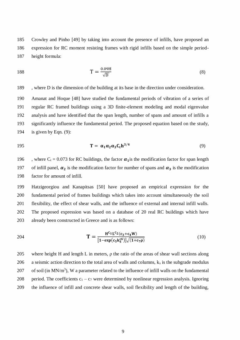
Crowley and Pinho [49] by taking into account the presence of infills, have proposed an 185
expression for RC moment resisting frames with rigid infills based on the simple period-186
height formula: 187
T 噺 待┻待苔滝ヂ第 (8) 188
, where D is the dimension of the building at its base in the direction under consideration. 189
Amanat and Hoque [48] have studied the fundamental periods of vibration of a series of 190
regular RC framed buildings using a 3D finite-element modeling and modal eigenvalue 191
analysis and have identified that the span length, number of spans and amount of infills a 192
significantly influence the fundamental period. The proposed equation based on the study, 193
is given by Eqn. (9): 194
桑 噺 膳層膳匝膳惣隅憩刑惣 想エ (9) 195
, where Ct = 0.073 for RC buildings, the factor 詩層is the modification factor for span length 196
of infill panel, 詩匝 is the modification factor for number of spans and 詩惣 is the modification 197
factor for amount of infill. 198
Hatzigeorgiou and Kanapitsas [50] have proposed an empirical expression for the 199
fundamental period of frames buildings which takes into account simultaneously the soil 200
flexibility, the effect of shear walls, and the influence of external and internal infill walls. 201
The proposed expression was based on a database of 20 real RC buildings which have 202
already been constructed in Greece and is as follows: 203
桑 噺 屈隅層 靴隅匝岫卦惣袋卦想君岻範層貸祁景径盤卦捜圭繰卦掃匪飯紐岫層袋卦挿素岻 (10) 204
where height H and length L in meters, と the ratio of the areas of shear wall sections along 205
a seismic action direction to the total area of walls and columns, ks is the subgrade modulus 206
of soil (in MN/m3), W a parameter related to the influence of infill walls on the fundamental 207
period. The coefficients c1 – c7 were determined by nonlinear regression analysis. Ignoring 208
the influence of infill and concrete shear walls, soil flexibility and length of the building, 209

10
Hatzigeorgiou and Kanapitsas [50] give a simpler expression for the fundamental period 210
which is very similar to the formula by Eurocode 8: 211
む 噺 ど┻どばぬ�待┻胎替泰 (11) 212
Kose [2] investigated the fundamental period of vibration of RC frame buildings using a 213
computational iterative modal analysis in 3D. He evaluated the effect of building height, 214
frame type and the presence of infill walls, among other parameters and he proposed the 215
expression of Eqn. (12) for the prediction of the fundamental period of reinforced concrete 216
moment resisting frames: 217 T 噺 ど┻どひぬの 髪 ど┻どぬどな� 髪 ど┻どなのはB 髪 ど┻どぬひF 伐 ど┻なはのはS ‒ ど┻どにぬに� (12) 218
where H = height of building in meters, B = number of bays, F = frame type equal to 1 for 219
frames with infills, 2 for frames with open first floor and 3 for bare frames, S - ratio in 220
percentage of shear walls to total floor area, I = area ratio of infill walls to total panels. For 221
the infilled frames, the fundamental period of vibration was found to be 5 to 10% lower than 222
that of RC frames without infill walls, regardless of the presence of shear walls. Based on a 223
sensitivity analysis undertaken by Kose [2] and since the fundamental period is not that 224
sensitive to the number of bays and frame type, a more convenient formula was derived 225
taking into account only the building height and the area ratio of infill walls to total panels: 226 T 噺 ど┻なぬはば 髪 ど┻どぬどな� 伐 ど┻なははぬS 伐 ど┻どぬどの� (13) 227
It is evident from the aforementioned review that the proposed empirical expressions for the 228
evaluation of fundamental period of vibration present similarities, in terms of the parameters 229
used to express the period value, e.g. building total height and length, percentage of infill 230
and span length of infill but at the same time provide values for the fundamental period with 231
significant spread. Further, a trustworthy expression for the evaluation of fundamental period 232
must simultaneously consider, besides the total height and length of the RC frame, other 233
parameters such as the frame height-to-length aspect ratio, infill height-to-length aspect 234
ratio, the percentage of infill opening, the relative panel-to-frame-stiffness and the presence 235
of soft story. Such parameters need further investigation, in order to assess their importance 236

11
and impact of the fundamental period and propose refined expressions for a more accurate 237
period evaluation. 238
3 OMPUTATIONAL STRUCTURAL MODELING 239
Since the first attempts to model the response of the composite infilled-frame structures, 240
experimental and conceptual observations have indicated that a diagonal strut with 241
appropriate geometrical and mechanical characteristics could possibly provide a solution to 242
the problem (Fig. 2). 243
hh w
Lw
d
è
w
L
z
detachmentframe-infill
detachmentframe-infill
244 Fig. 2. Masonry infill frame sub-assemblage 245
246
Early research on the in-plane behavior of infilled frame structures undertaken at the 247
Building Research Station, Watford (later renamed Building Research Establishment, and 248
now simply BRE) in the 1950s served as an early insight into this behavior and confirmed 249
its highly indeterminate nature in terms solely of the normal parameters of design [51]-[53]. 250
On the basis of these few tests a purely empirical interaction formula was later tentatively 251
suggested by Wood [54] for use in the design of tall framed buildings. By expressing the 252
composite strength of an infilled frame directly in terms of the separate strengths of the frame 253
and infill, he short-circuited a mass of confusing detail and he recognized the desirability of 254
a higher load factor where strengths were most dependent on the infills. 255

12
3.1 Infill Walls Modeling 256
In the early sixties, Polyakov [55] suggested the possibility of considering the effect of the 257
infilling in each panel as equivalent to diagonal bracing, and this suggestion was later 258
adopted by Holmes [56], who replaced the infill by an equivalent pin-jointed diagonal strut 259
made of the same material and having the same thickness as the infill panel and a width 260
defined by 261
3
1
d
w (14) 262
where d is the diagonal length of the masonry panel. The “one-third” rule was suggested as 263
being applicable irrespective of the relative stiffness of the frame and the infill. One year 264
later, Stafford Smith [57], based on experimental data from a large series of tests using 265
masonry infilled steel frames, found that the ratio w/d varied from 0.10 to 0.25. On the 266
second half of the sixties Stafford Smith and his associates using additional experimental 267
data [3], [58], [59] related the width of the equivalent diagonal strut to the infill/frame contact 268
lengths using an analytical equation, which has been adapted from the equation of the length 269
of contact of a free beam on an elastic foundation subjected to a concentrated load [60]. They 270
proposed the evaluation of the equivalent width as a function of the relative panel-to-frame-271
stiffness parameter, in terms of 272
4
4
2sin
w
wwh EIh
tEh
(15) 273
where Ew is the modulus of elasticity of the masonry panel, EI is the flexural rigidity of the 274
columns, tw the thickness of the infill panel and equivalent strut, h the column height between 275
centerlines of beams, hw the height of infill panel, and し the angle, whose tangent is the infill 276
height-to-length aspect ratio, being equal to 277
w
w
L
h1tan (16) 278
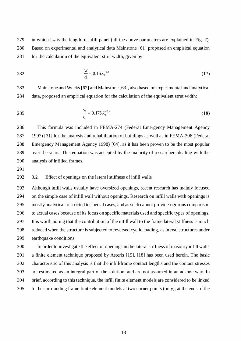
13
in which Lw is the length of infill panel (all the above parameters are explained in Fig. 2). 279
Based on experimental and analytical data Mainstone [61] proposed an empirical equation 280
for the calculation of the equivalent strut width, given by 281
3.016.0 hd
w (17) 282
Mainstone and Weeks [62] and Mainstone [63], also based on experimental and analytical 283
data, proposed an empirical equation for the calculation of the equivalent strut width: 284
4.0175.0 hd
w (18) 285
This formula was included in FEMA-274 (Federal Emergency Management Agency 286
1997) [31] for the analysis and rehabilitation of buildings as well as in FEMA-306 (Federal 287
Emergency Management Agency 1998) [64], as it has been proven to be the most popular 288
over the years. This equation was accepted by the majority of researchers dealing with the 289
analysis of infilled frames. 290
291
3.2 Effect of openings on the lateral stiffness of infill walls 292
Although infill walls usually have oversized openings, recent research has mainly focused 293
on the simple case of infill wall without openings. Research on infill walls with openings is 294
mostly analytical, restricted to special cases, and as such cannot provide rigorous comparison 295
to actual cases because of its focus on specific materials used and specific types of openings. 296
It is worth noting that the contribution of the infill wall to the frame lateral stiffness is much 297
reduced when the structure is subjected to reversed cyclic loading, as in real structures under 298
earthquake conditions. 299
In order to investigate the effect of openings in the lateral stiffness of masonry infill walls 300
a finite element technique proposed by Asteris [15], [18] has been used herein. The basic 301
characteristic of this analysis is that the infill/frame contact lengths and the contact stresses 302
are estimated as an integral part of the solution, and are not assumed in an ad-hoc way. In 303
brief, according to this technique, the infill finite element models are considered to be linked 304
to the surrounding frame finite element models at two corner points (only), at the ends of the 305

14
compressed diagonal of the infill (points A and B in Fig. 3a). Then, the nodal displacements 306
are computed and checked whether the infill model points overlap the surrounding frame 307
finite elements. If the answer is positive, the neighboring points (to the previously linked) 308
are also linked and the procedure is repeated. If the answer is negative, the procedure is 309
stopped and the derived deformed mesh is the determined one (Fig. 3h). 310
311
(a) 1st derived mesh (b) 2nd derived mesh
(c) 3rd derived mesh (d) 4th derived mesh
(e) 5th derived mesh (f) 6th derived mesh
(g) 7th derived mesh (h) 8th-final derived mesh
A A
A A
A A
A A
BB
B B
B B
B B
312 Fig. 3. Deformed meshes of an one-storey one-bay infilled frame using the finite element technique 313 proposed by Asteris [15], [18]. 314

15
315
Fig. 4. Infill panel stiffness reduction factor in relation to the opening percentage 316 317
Using this technique, analytical results are presented on the influence of the opening size 318
on the seismic response of masonry infilled frames. Fig. 4 shows the variation of the そ factor 319
as a function of the opening percentage (opening area/infill wall area), for the case of an 320
opening on the compressed diagonal of the infill wall (with aspect ratio of the opening the 321
same as that of the infill). As expected, the increase in the opening percentage leads to a 322
decrease in the frame’s stiffness. Specifically, for an opening percentage greater than 50% 323
the stiffness reduction factor tends to zero. 324
The findings of the present parametric study using the finite-element method, lead to the 325
following relationship for the infill wall stiffness reduction factor そ: 326
14154021
..ww (19) 327
in which gw is the infill wall opening percentage (area of opening to the area of infill wall). 328
The above coefficient could be used to find the equivalent width of a strut for the case of 329
an infill with opening by multiplying the results of Eqns 14, 17 and 18 above. It can also be 330
used to modify the equations of the Crisafulli model, which is described below. 331
332 333
0.00 0.20 0.40 0.60 0.80 1.000.00
0.20
0.40
0.60
0.80
1.00
Infill Panel Opening Percentage w
Infil
l Pan
el S
tiffn
ess
Red
uctio
n F
acto
r
Proposed equation =1-2w0.54+w
1.14
Finite Element Method

16
4 DESCRIPTION OF THE INVESTIGATED STRUCTURES 334
4.1 Building forms 335
The fundamental period of high rise RC structures are examined in this study. Buildings 336
considered are frame systems regular in plan, comprised by beams and columns. Thus, only 337
one frame is finally considered and planar analysis is done. The buildings are cast-in-place 338
reinforced concrete structures with beams cast monolithically with slabs and supported by 339
columns. 340
341
Buildings examined have 14 storeys in order to examine the influence of the number of 342
storeys. The storey height for all buildings is 3.0 m. The number of spans ranges form 2, 4 343
and 6. For each case, three different span lengths are examined, namely 3.0 m, 4.5 m and 6.0 344
m. In the perpendicular direction the bay size is 5 m, which is common for all buildings. 345
346
4.2 Influence of infill panels 347
The influence of infill walls is examined analyzing both bare frame structures as well as 348
structures with fully or partially unreinforced masonry infilled frames with or without 349
openings. Various parameters are considered for each case. Infill panels are 0.25 m thick, 350
following the conventional construction of single and double leaf walls. The influence of 351
infill wall openings is also examined. Infill wall openings are given as a percentage of the 352
panel area. Five different cases for infill wall openings are studied. That is fully infilled walls 353
(0% openings), infill walls with small and large openings (25%, 50% and 75% openings) 354
and bare frames (100% openings). 355
Finally, three values for the masonry strength were adopted to represent weak, medium and 356
strong clay brick masonry, namely 1.5 MPa, 3.0 MPa and 4.5 MPa. These values are 357
assumed to cover the most common cases for masonry infill condition. 358
The building parameters are listed in Table 2. 359
360
Table 2. Building parameters 361 Concrete strength 25 MPa

17
Modulus of elasticity of concrete, Ec 31 Gpa Steel tensile yield strength 500 MPa Size of beams 25/50 (bay size 3.0m), 25/60 (bay size 4.5 m, 6.0m) Slab thickness 15 cm Dead loads 1.50 kN/m2 + 0.90 kN/m2 Live loads 3.50 kN/m2 Number of floors 2, 4, 6, 8, 10, 12, 14 Building height 14 m Bay size 3.0 m, 4.5 m, 6.0m Number of bays 2, 4, 6 Masonry compressive strength, fm 1.5 MPa, 3.0 MPa and 4.5 MPa Modulus of elasticity of masonry, Em 1.5 GPa, 3.0 GPa and 4.5 GPa Thickness of infill panel, tw 25 cm Infill wall opening percentage 0% (fully infilled, 25%, 50%, 75%, 100% (bare frame)
362
4.3 Structural design of structures 363
The frames are designed according to Eurocodes using the software FESPA [65]. Modal 364
response spectrum analysis is performed. The frames are designed for seismic zone I with 365
reference peak ground acceleration on type A ground, agR = 0.16 g. The importance factor けI 366
is 1.0 and ground type is B with soil factor S = 1.2. Frames are designed for medium ductility 367
class (DCM) and the behaviour factor, q is 3.45 for both horizontal directions. Concrete 368
strength class C25/30 was used for beams and columns, while steel grade B500c was used 369
for reinforcement steel bars. Dead loads are self-weight of the structure, 1.50 kN/m2 plus 370
0.90 kN/m2 to include interior partition walls in the mass of the building. Live load is 3.5 371
kN/m2. 372
373
Slabs are 15 cm thick for all cases. Beams are 250/500 [mm] for frames with 3.0 m bay size 374
and 250/600 [mm] for frames with 4.5 and 6.0 m bay sizes. Columns are rectangular for all 375
frames. Columns dimensions vary from 650x650 [mm] at the ground floor to 500x500 [mm] 376
at the roof for the 14storey frame with 6.0 m bay size. On the contrary, the 3 storey frame 377
with 3.0 m bay size has column dimensions 350x350 [mm] at both storeys. Column 378
longitudinal reinforcement ratio was kept low and ranges between 1.0% and 1.5%, with most 379
cases being under 1.15%. Column dimensions for all frames are shown in detail in Error! 380
Reference source not found.. Column dimensions were kept the same for buildings with 381
the same number of storeys, same bay size but different number of bays. 382

18
383
Table 3. Side dimension (cm) of rectangular columns 384
Storey Column’s Dimensions (cm)
Bay size 3.0 m Bay size 4.5 m Bay size 6.0 m 14 40 40 50 13 45 45 55 12 45 45 55 11 45 50 55 10 50 50 55 9 50 50 55 8 50 50 60 7 50 55 60 6 50 55 60 5 50 60 65 4 55 60 65 3 55 60 65 2 55 60 65 1 55 60 65
385 386
4.4 Modelling of structures 387
All buildings are modelled as plane frames using Seismostruct [66]. A plastic-hinge element 388
has been adopted for beams and columns, with concentrated inelasticity within a fixed length 389
at each member’s end. The Mander et al. [67] model, later modified by Martinez-Rueda and 390
Elnashai [68], has been assumed for the core and the unconfined concrete, while Menegotto-391
Pinto steel model has been adopted for the reinforcement steel [69]. Concrete compressive 392
strength is 25 MPa and yield strength of steel is 500 MPa. Mass is calculated from seismic 393
load combination, namely dead loads + 30% live loads. 394
395
Masonry is modelled using the inelastic infill panel element. This is an equivalent strut 396
nonlinear cyclic model proposed by Crisafulli [70] for the modelling of the nonlinear 397
response of infill panels in framed structures. Each panel is represented by six strut members. 398
Each diagonal direction features two parallel struts to carry axial loads across two opposite 399
diagonal corners and a third one to carry the shear from the top to the bottom of the panel 400
(Fig. 5). This latter strut only acts across the diagonal that is on compression, hence its 401
"activation" depends on the deformation of the panel. The axial load struts use the masonry 402

19
strut hysteresis model, while the shear strut uses a dedicated bilinear hysteresis rule, as 403
described by Crisafulli [70]. 404
405
Fig. 5. Infill panel element proposed by Crisafulli [70] 406
407
Four internal nodes are employed to account for the actual points of contact between the 408
frame and the infill panel (i.e. to account for the width and height of the columns and beams, 409
respectively), whilst four dummy nodes are introduced with the objective of accounting for 410
the contact length between the frame and the infill panel (Fig. 5). All the internal forces are 411
transformed to the exterior four nodes where the element is connected to the frame. 412
413
5 RESULTS AND DISCUSSION 414
5.1 Influence of number of spans on the fundamental period 415
Figure 6 shows the relationship between the determined fundamental period versus the 416
number of spans for both the designed and non-designed bare and fully infilled 14 storey RC 417
frames. The time periods obtained from the eigenvalue analysis are also compared against 418
the period obtained from EC8 and that from Goel and Chopra (2000). From Figure 6 and 419
Table 4, it is shown that the fundamental period obtained from modal analysis for both the 420
designed and non-designed 14 storey RC infilled frames with span lengths ranging from 3m 421
to 6 m is not influenced by number of spans (Fig. 6b & 6d). Also, the fundamental period 422
for both the designed and non-designed 14 storey RC bare frames with span lengths ranging 423
from 4.5 to 6 m is not influenced by the number of spans (Fig. 6a & 6c). However, the span 424

20
length does affect the fundamental period of the building. For the bare frame with two spans 425
and span length equal to 3 m (Fig 6a & 6c), the fundamental period is higher when compared 426
to the same frame with four number of spans. The reference building is fourteen storeys. 427
Thus, when there are two spans, the building becomes relatively slender and more flexible, 428
since a cantilever action comes into effect against lateral sway, resulting in longer period. It 429
may be mentioned that although a span length equal to 3 m is not common in practice. Such 430
theoretical span is used herein to have some general ideal of the characteristics of the RC 431
frame even in these extreme conditions. Code equations are not capable to reflect the effect 432
of the number of spans and span length. The equations from EC8 and that of Goel and Chopra 433
(2000) do not have any provision to incorporate the effect of the number of spans in 434
determining the time period, since there is no parameter relevant to span in the code 435
equations. Moreover, from Fig. 6a, the modal analysis for the designed bare frame resulted 436
in periods falling within the region of those estimated by the code equations and that of Goel 437
and Chopra (2000). On the other hand, from Fig. 6b & 6d, for the designed fully infilled 438
frame and that of the non-designed infilled frame, it is apparent that the values of the 439
determined fundamental period are lower than those obtained from EC8 as well as that from 440
Goel and Chopra (2000). However, from Fig. 6c, for the non-designed fully infilled frame, 441
the values of the fundamental period determined using modal analysis, are higher than those 442
estimated from the code equations and Goel and Chopra (2000). 443
444
a) Designed bare frame b) Designed fully infilled frame 445

21
446
c) Non Designed bare frame d) Non-Designed fully infilled frame 447
448 Fig. 6. Influence of Number of spans on Fundamental Period of a 14-storey RC frame 449
450 451
Table 4: Fundamental Period of a 14-storey concrete frame 452 453
Case
Number
of
Spans
Bare Frame Fully Infilled Frame
Span Length Span Length
3.0 4.5 6.0 3.0 4.5 6.0
Des
igne
d F
ram
e
2 1.413 1.597 1.887 0.860 0.893 0.967
4 1.273 1.547 1.863 0.823 0.878 0.958
6 1.230 1.532 1.856 0.809 0.872 0.954
Non
D
esig
ned
Fra
me
2 2.300 2.619 3.017 1.078 1.167 1.277
4 2.182 2.635 3.093 1.064 1.164 1.281
6 2.161 2.653 3.130 1.058 1.163 1.283
Note: Masonry wall Modulus of Elasticity E=1500 Mpa;
Masonry wall Thickness t=0.15 m;
Masonry Wall Stiffness Et=2.25E+05 kN/m

22
454
5.2 Influence of span length on the fundamental period 455
Figure 7 shows the relationship between the determined fundamental period versus the spans 456
length for both the designed and non-designed bare and fully infilled 14 storey RC frames. 457
Similarly, the time periods obtained from the eigenvalue analysis are also compared against 458
the period obtained from code equations and that from Goel and Chopra (2000). From Figure 459
7 and Table 4, increasing the span length decreases the period of the RC building. This 460
observed for both designed and non-designed bare and fully infilled 14 storey RC frames. 461
Also, for the estimation of the time period of a building, both the code equations and the 462
relationship derived from Goel and Chopra (2000) do not have any provision to incorporate 463
the effect of span lengths in the direction of motion. Therefore, the periods predicted by these 464
equations are the same for all values of span length studied. However, for the designed bare 465
frame (Fig. 7a), the values of the determined fundamental period falling within the range of 466
the values suggested by the code equations as well as that from Goel and Chopra (2000). 467
But, this is not the case for the rest of the cases studied. From, Fig. 7a & Fig.7d, it can be 468
observed that at 6 m span, the period is about the same as that obtained from the code 469
equation. The period decreases for smaller spans. This is due to the fact, that for longer 470
spans, the stiffness contribution of the infill decreases (Madan et al. 1997). In the future, 471
further works will be undertaken to investigate the case when the span length is 7.5 m. From 472
Figure 8a, it can be seen that the period increases by about 45 % for each 3 m change in span 473
from the reference value of 3m for the non-designed bare frame and by 31% for the designed 474
bare 14 storey RC frame with six spans. Similarly, from figure 8b and for the fully infilled 475
frame, the period increases by about 21% for each 3 m change in span from the reference 476
value of 3 m for the non-designed frame and by 8% for the designed 14 storey RC frame 477
with six spans. 478

23
479 a) Designed bare frame b) Designed fully infilled frame 480
481
c) Non Designed bare frame d) Non Designed fully infilled frame 482
Fig. 7. Influence of Number of spans on Fundamental Period of a 14-storey concrete frame 483 484 485 486

24
487 a) Bare frame b) Fully in-filled 488
Fig. 8. Influence of design on Fundamental Period of a 14-storey concrete frame (Number of spans 489 6) 490 491
5.3 Influence of infill masonry panel stiffness on Fundamental Period お ヾそgかjすて 492
Figure 9 and Table 6 shows the determined fundamental period versus the column stiffness 493
(EI/L) for both the designed and non-designed 14 storey infilled RC frame for six of spans 494
with lengths ranging from 3 to 6 m. The mechanical characteristics of the masonry infill 495
panels is shown in Table 6. From Figure 9, the period is highly sensitive to the infill wall 496
panel stiffness. Infills act as diagonal bracing and resist lateral deflection. So, increasing the 497
infill wall panel stiffness, increases the lateral deflection and reduces the fundamental period. 498
For the design RC frame (Fig. 9a), it seems that for the same infill wall stiffness, the change 499
in span length does not vary the fundamental period. However, this is not the case for the 500
non-designed frame (Fig 9b), where for the same stiffness of the infill, the fundamental 501
period increases proportionally with the span length. Finally, from Figure 9a, it can be seen 502
that the fundamental period of the 14 storey RC frame decreases by about 57 % for a change 503
in infill wall stiffness from each 2.5 x 10⁵ to 25 x 105 KN/m for the designed frame and by 504
54% for the non-designed frame with six spans. We can conclude that the decrease of the 505
fundamental period as a result of the influence of infill masonry panel stiffness is almost the 506
same for the designed and non-designed 14 storey RC frame. 507
508 509

25
510 a) Designed b) Non-designed 511
512 Fig. 9. Influence of masonry stiffness on Fundamental Period of a 14-storey fully infilled concrete 513 frame (Number of spans 6) 514 515 Table 5: Mechanical Characteristics of Masonry Infill panels 516
Case of infill panel
Modulus of Elasticity E
(Mpa)
Thickness t (m) Stiffness Et [x105 kN/m]
1 1,500 0.15 2.25
2 3,000 0.15 4.50 3 3,000 0.25 7.50 4 4,500 0.25 11.25 5 10,000 0.15 15.00 6 8,000 0.25 20.00 7 10,000 0.25 25.00
517 Table 6: Fundamental Period of a six-span-14-storey fully infilled concrete frame for different span 518 lengths 519
Masonry Wall Stiffness
Et [x105 kN/m]
Designed Frame Non Designed Frame
Span Length Span Length
3.0 4.5 6.0 3.0 4.5 6.0 2.25 0.809 0.872 0.954 1.058 1.163 1.283
4.50 0.665 0.695 0.747 0.828 0.904 0.996
7.50 0.587 0.604 0.643 0.715 0.782 0.865
11.25 0.511 0.521 0.551 0.614 0.675 0.751
15.00 0.444 0.450 0.474 0.529 0.584 0.654
20.00 0.417 0.422 0.443 0.496 0.554 0.624
25.00 0.385 0.389 0.408 0.458 0.515 0.584
520

26
5.4 Influence of the infill openings percentage on the fundamental period of infilled 521
frames 522
Figure 10 shows the influence of opening percentage on fundamental period of a 14-storey 523
fully infilled designed RC frame with six number of spans and span length equal to 6 m. 524
From Figure 10a, as the opening percentage decreases from full infill to 80%, the 525
fundamental period increases almost linearly. However, when the opening percentage is 526
above 80% up to the bare frame, the opening does not affect the fundamental periods. This 527
is due to the fact that when the opening is above 85%, the mass and stiffness of the infill 528
does not contribute to the fundamental period. However, this is not the case for the designed 529
frame (see Figure 10b). More specifically, for the non-designed frame, as the opening in the 530
infill panel increases from a full infill to bare frame, the fundamental period of the structure 531
increases. Finally, for both the designed and non-designed frames with the same opening, 532
the higher the masonry stiffness, the lower the fundamental period. For the designed frame 533
and for values of Et ranging from 2.25 to 25 x 105 kN/m, the fundamental perid ranges from 534
0.4 to 1.8. However, for the non-designed frame, the fundamental period varied from 535
approximately 0.6 to 3.1. 536
537
538 539
a) Designed b) Non designed 540 541 Fig. 10. Influence of opening percentage on Fundamental Period of a 14-storey fully infilled concrete 542 frame (Number of spans 6; Span length=6.00 m) 543
544 545

27
Table 7: Fundamental Period of a 14-storey partially infilled concrete frame 546
Case
Masonry Wall
Stiffness Et
[x105 kN/m]
Opening Percentage Reduction
[%]
0.00 25.00 50.00 75.00 100.00
Des
igne
d F
ram
e
2.25 0.954 1.421 1.705 1.863 1.856 48.57 4.50 0.747 1.202 1.568 1.841 1.856 59.72 7.50 0.643 1.068 1.468 1.837 1.856 65.33 11.25 0.551 0.936 1.346 1.806 1.856 70.29 15.00 0.474 0.820 1.226 1.758 1.856 74.45 20.00 0.443 0.763 1.159 1.744 1.856 76.12 25.00 0.408 0.703 1.086 1.713 1.856 78.03
Reduction [%] 57.28 50.52 36.32 8.06 0.00
Non
Des
igne
d F
ram
e
2.25 1.283 2.051 2.664 3.112 3.130 59.01 4.50 0.996 1.667 2.355 3.049 3.130 68.17 7.50 0.865 1.452 2.139 3.012 3.130 72.37 11.25 0.751 1.256 1.912 2.930 3.130 76.00
15.00 0.654 1.093 1.711 2.820 3.130 79.11 20.00 0.624 1.018 1.596 2.769 3.130 80.06 25.00 0.584 0.938 1.479 2.691 3.130 81.32
Reduction [%] 54.44 54.27 44.46 13.53 0.00
Note: Number of spans =6; Span length=6.00 m 547 548
5.5 Influence of soft storey on the fundamental period 549
Figure 11 shows influence of soft storey position on the fundamental period of a 14-storey 550
fully infilled concrete frame with six spans. From Figure 11b and 11c we can see that for the 551
non designed frame, the higher fundamental period occurs when the soft storey is at the first 552
floor. From Figure 11a and for the designed RC frame with span length equal to 3 m, the 553
fundamental period is high when the soft storey is located at the second and fifth floor of the 554
building. From Figure 11b, and for the designed frame with a span length equal to 6 m, the 555
higher fundamental period occurs when the soft storey is at the second floor. Also, from 556
Table 8, the change of the fundamental period when the soft storey is at the first floor and 557

28
when it is at the fourteenth floor increases from 7 to 40%. Also, this effect becomes less for 558
lower values of stiffness. 559
560
561 a) Designed, Span length=3.00 m b) Designed Span length=6.00 m 562
563
564 c)Non-designed, Span length=3.00 m d) Non-designed, Span length=6.00 m 565
566 Fig. 11. Influence of soft storey position on Fundamental Period of a 14-storey fully infilled concrete 567 frame (Number of spans 6) 568

29
Table 8: Fundamental Period of a 14-storey partially infilled concrete frame for different position of soft storey 569 570
Ca
se Span
length [m]
Masonry Wall
Stiffness Et
[x105 kN/m]
Soft Storey
Increase %
1 2 3 4 5 6 7 8 9 10 11 12 13 14
De
sig
ne
d 3
2.25 0.830 0.853 0.851 0.848 0.855 0.849 0.842 0.836 0.827 0.819 0.816 0.807 0.800 0.797 7.28
11.25 0.575 0.602 0.596 0.590 0.602 0.592 0.581 0.570 0.555 0.541 0.536 0.520 0.507 0.501 20.22
25.00 0.479 0.502 0.495 0.488 0.503 0.492 0.479 0.467 0.449 0.431 0.427 0.405 0.387 0.379 32.79
6
2.25 0.986 1.045 1.039 1.033 1.025 1.023 1.011 1.000 0.993 0.978 0.964 0.952 0.944 0.939 11.23
11.25 0.629 0.685 0.673 0.664 0.655 0.657 0.643 0.630 0.624 0.602 0.581 0.561 0.547 0.539 27.00
25.00 0.517 0.561 0.552 0.543 0.534 0.538 0.524 0.511 0.506 0.482 0.456 0.431 0.411 0.401 40.06
No
n D
esi
gn
ed
3
2.25 1.257 1.244 1.236 1.224 1.210 1.196 1.178 1.170 1.140 1.115 1.091 1.069 1.052 1.042 20.59
11.25 1.015 0.977 0.959 0.936 0.911 0.888 0.859 0.847 0.798 0.754 0.708 0.664 0.623 0.603 68.24
25.00 0.951 0.904 0.881 0.855 0.826 0.801 0.769 0.757 0.703 0.654 0.601 0.544 0.485 0.454 109.29
6
2.25 1.638 1.624 1.606 1.582 1.555 1.530 1.497 1.481 1.431 1.388 1.346 1.309 1.279 1.264 29.57
11.25 1.385 1.335 1.306 1.269 1.229 1.193 1.148 1.128 1.055 0.988 0.916 0.843 0.774 0.739 87.47
25.00 1.323 1.263 1.230 1.189 1.146 1.109 1.061 1.042 0.964 0.893 0.814 0.728 0.634 0.582 127.45
571
572

30
6 CONCLUSIONS 573
An investigation has been performed on the fundamental natural period of vibration of high 574
rise RC bare and infilled-frame buildings by means of a finite-elements modelling. As a base 575
study, a 14 storey designed and non-designed RC building has been considered. Some 576
sensitivity analysis has been undertaken to study the influence of geometric and stiffness 577
parameters on the fundamental period of the structure. More specifically, the parameters 578
investigated include: a) the number of spans; b) the influence of span length in the direction 579
of motion; c) the influence of infill stiffness in the structure; d) the infill panel percentage 580
opening and; e) the soft storey position. The time periods obtained from the eigenvalue 581
analysis were also compared against the period obtained from EC8 and that from other 582
researchers including Goel and Chopra (2000). From the results analysis it was found the 583
span length of the panel, the stiffness of the infill wall panel and the location of the soft 584
storey in the structure are some of the important parameters influencing the natural period. 585
However, code equations do not take into account the above parameters and inaccurately 586
predict the natural period of a structure. This study also shows that varying the number of 587
spans from three to six does not have a significant effect on the period. Instead, an increase 588
a change in the span length will significantly contribute to the period. More specifically, 589
from the sensitivity analysis it was found: 590
Increasing the span length decreases the period of the RC building; 591
An increase of the infill wall panel stiffness will increase the lateral deflection and 592
reduce the fundamental period by approximately 57% for a designed frame and for 593
wall stiffness ranging from 2.5 x 10⁵ to 25 x 105 KN/m; 594
Fort he designed frame, as the opening decreases from full infill to 80% opening, 595
the fundamental period of the structure increases almost linearly. However, when 596
the opening percentage is 80% and above, the increase of the opening does not 597
affect the fundamental period of the structure; 598
For both the designed and non-designed frames with the same opening, the higher 599
the masonry stiffness, the lower the fundamental period; 600

31
For the non designed frame, the higher fundamental period occurs when the soft 601
storey is at the first floor; 602
The location of the soft storey in the structure and the length of the span in the 603
direction of motion significantly affect the fundamental period of the structure. For 604
the designed frame with span length equal to 3 m, the fundamental period is high 605
when the soft storey is located at the second and fifth floor of the building.For the 606
designed frame with a span length equal to 6 m, the higher fundamental period 607
occurs when the soft storey is at the second floor 608
609
In order to undertake a more generalized suggestion regarding the determination and 610
influence of the buildings period, in the future the fundamental period of vibration of a 2, 4, 611
6 8 and 10 m height building and their sensitivity to the above studied parameters will be 612
investigated. 613
REFERENCES 614
[1] El-Dakhakhni W.W., Elgaaly M., Hamid A.A., Three-Strut model for concrete 615
masonry-infilled frames,J. Struct. Eng., ASCE, 129(2), 177-185, 2003. 616
[2] Kose M.M., Parameters affecting the fundamental period of RC buildings with infill 617
walls, Engineering Structures, 31, 93-102, 2009. 618
[3] Smith B.S., Behavior of square infilled frames,J. Struct. Div., ASCE, ST1, 381-403, 619
1966. 620
[4] Smith B.S., C. Carter, A method of analysis for infilled frames, Proc., Instn. Civ. 621
Engrs., 44, 31-48, 1969. 622
[5] Page A.W., Kleeman P.W., Dhanasekar M., An In-Plane Finite Element Analysis 623
Model for Brick Masonry, Proc. of a session held in conjunction with Structures 624
Congress’85, Chicago, Ill, 1-18, 1985. 625
[6] Mehrabi A.B., Shing P.B., Schuller M., Noland J., Experimental evaluation of 626
masonry-infilled RC frames,J. Struct. Engrg., ASCE, 122(3), 228-237, 1966. 627

32
[7] Buonopane S.G., White R.N., Pseudodynamic Testing of Masonry Infilled 628
Reinforced Concrete Frame,J. Struct. Eng., ASCE, 125(6), 578-589, 1999. 629
[8] Santhi M.H., Knight G.M.S., Muthumani K., Evaluation of seismic response of soft-630
storeyinfilled frames,Computers and Concrete, 2 (6), 423-437, 2005. 631
[9] Santhi M.H., Knight G.M.S., Muthumani K., Evaluation of Seismic Performance of 632
Gravity Load Designed Reinforced Concrete Frames,Journal of Performance of 633
Constructed Facilities, 19(4), 277-282, 2005. 634
[10] Liauw T.C., Kwan K.H., Nonlinear behaviour of non-integral infilled frames,Comp. 635
and Struct.,18, 551-560, 1984. 636
[11] Dhanasekar M., Page A.W., Influence of brick masonry infill properties on the 637
behaviour of infilled frames, Proc., Instn. Civ. Engrs., London, Part 2, 81, 593-605, 638
1986. 639
[12] Chrysostomou C.Z., Effects of degrading infill walls on the nonlinear seismic 640
response of two-dimensional steel frames, PhD thesis, Cornell University, Ithaca, 641
N.Y, 1991. 642
[13] Saneinejad A., B. Hobbs, Inelastic design of infilled frames,J. Struct. Engrg., ASCE, 643
121(4), 634-650, 1995. 644
[14] Chrysostomou C.Z., Gergely P., Abel J.F., A six-strut model for nonlinear dynamic 645
analysis of steel infilled frames, International Journal of Structural Stability and 646
Dynamics, 2(3), 335-353, 2002. 647
[15] Asteris P.G., Lateral stiffness of brick masonry infilled plane frames,J. Struct. Eng., 648
ASCE, 129(8), 1071-1079, 2003. 649
[16] Moghaddam H.A., Lateral Load Behavior of Masonry Infilled Steel Frames with 650
Repair and Retrofit,J. Struct. Engrg., ASCE, 130(1), 56-63, 2004. 651
[17] Asteris P.G., Closure to Lateral Stiffness of Brick Masonry Infilled Plane Frames by 652
P. G. Asteris, J. Struct. Engrg. ASCE, 131(3), 523-524, 2005. 653
[18] Asteris P.G., Finite Element Micro-Modeling of Infilled Frames,Electronic Journal 654
of Structural Engineering, 8, 1-11, 2008. 655
[19] Kakaletsis D.J., Karayannis C.G., Experimental Investigation of Infilled Reinforced 656
Concrete Frames with Openings, ACI Structural Journal, 106(2), 132-141, 2009. 657

33
[20] Moghaddam H.A., Dowling P.J., The State of the Art in Infilled Frames, ESEE 658
Research Report No. 87-2, Imperial College of Science and Technology, Civil Eng. 659
Department, London, U.K, 1987. 660
[21] Asteris P.G., Antoniou S.T., Sophianopoulos D.S., Chrysostomou C.Z., 661
Mathematical Macromodeling of Infilled Frames: State of the Art, J. Struct. Engrg., 662
ASCE, Vol. 137, No. 12, pp. 1508-1517, 2011. 663
[22] Chrysostomou, C.Z., Asteris, P.G. (2012). On the in-plane properties and capacities 664
of infilled frames, Engineering Structures, ELSEVIER, Volume 41, August 2012, 665
Pages 385-402. 666
[23] Asteris, P.G., Cotsovos, D.M., Chrysostomou, C.Z., Mohebkhah, A., Al-Chaar, G.K. 667
(2013). Mathematical micromodeling of infilled frames: State of the Art, 668
Engineering Structures, ELSEVIER, Volume 56, Pages 1905-1921. 669
[24] Applied Technology Council (ATC). Tentative Provision for the development of 670
seismic regulations for buildings. Report No. ATC3-06. Applied Technology 671
Council. California. 1978. 672
[25] European Committee for Standardization CEN 2004. Eurocode 8: Design of 673
Structures for Earthquake Resistance - Part 1: General Rules, Seismic Actions and 674
Rules for Buildings. EuropeanStandard EN 1998-1:2004. 675
[26] Internal Conference of Building Officials. Uniform Building Code . California, 676
Wilier. 1997. 677
[27] Jordanian National Building Council, Jordanian National Building Code for 678
Earthquake-Resistant Buildings, Amman, Jordan, 2005. 679
[28] H. Al-Nimry, M. Resheidat, M. Al-Jamal, Ambient vibration testing of low and 680
medium rise infilled RC frame buildings in Jordan, Soil Dynamics and Earthquake 681
Engineering, 59, pages21-29, 2014. 682
[29] New Zealand Society of Earthquake Engineering (NZSEE), Assessment and 683
improvement of the structural performance of buildings in earthquakes, 684
Recommendations of a NZSEE Study Group on Earthquake Risk Buildings, 2006. 685
[30] Israel IC-413 (1994) SI 413 Design provision for Earthquake Resistant of structures. 686
StandardInstitute of Israel 1988. 687

34
[31] FEMA 450. NEHRP recommended provisions for seismic regulations for new 688
buildings amd other structures. Part 1: Provisions. Washington (DC): Federal 689
Emergency Management Agency; 2003 690
[32] Goel, R.K., Chopra, A.K. Period formulas for moment-resisting frame buildings. 691
Journal of Structural Engineering ASCE 1997: 123: 1454-61. 692
[33] National Research Council. The National Building Code (NBC). Canada; 1995 693
[34] Seismic Code of Costa Rica, Federal College of Engineers and Architects of Costa 694
Rica, Department of Design, Ministry of Construction, 1986. 695
[35] E.A.K., Greek Earthquake Resistant Design Code, Earthquake Design and Protection 696
Organization (OASP) and Technical Chamber of Greece (TEE), Athens, 2003. 697
[36] Bureau of Indian Standards, 2002. IS-1893, Indian Standard Criteria for Earthquake 698
Resistant Design of Structures—Part 1: General Provisions and Buildings, Fifth 699
Revision, New Delhi, India 700
[37] Egyptian Seismic Code, 1988. Regulations for Earthquake Resistant Design of 701
Buildings in Egypt, Egyptian Society for Earthquake Engineering, Cairo, Egypt 702
[38] Venezuelan Seismic Code, 1988. Regulations for Earthquake Resistant Buildings, 703
Comision De Normas Industriales, Covenin, Caracas, Venezuela. 704
[39] AFPS-90, Recommendations for the Redaction of Rules Relative to the Structures 705
and Installation Built in Regions Prone to Earthquakes, Frence Association of 706
Earthquake Engineering, Paris, France, 1990. 707
[40] Algerian Seismic Code, Algerian Earthquake Resistance Regulations, Ministry of 708
Town-planning and Construction, Algiers, Algeria, 1988 709
[41] M. Dolsek , P. Fajfar , Inelastic spectra for infilled reinforced concrete frames, 710
Earthquake Engineering and Structural Dynamics,34, pages 49-66, 2005. 711
[42] H. Crowley and R. Pinho, Period-height relationship for existing European 712
reinforced concrete buildings, Journal of Earthquake Engineering, 8 (1), pages 93-713
119, 2004. 714
[43] H. Crowley, R. Pinho, Simplified equations for estimating the period of vibration of 715
existing. Buildings, First European Conference on Earthquake Engineering and 716
Seismology, Geneva, 3–8 September 2006, Paper Number 1122. 717

35
[44] K. Guler ,E. Yuksel, A. Kocak, Estimation of the fundamental vibration period of 718
existing RC buildings in Turkey utilizing ambient vibration records. Journal of 719
Earthquake Engineering, 12(S2), pages 140–150, 2008 720
[45] L.L. Hong and W.L. Hwang, Empirical formula for fundamental vibration periods of 721
reinforced concrete buildings in Taiwan, Earthquake Engineering and Structural 722
Dynamics, 29 (3), pages 326-33, 2000. 723
[46] A.K. Chopra and R.K. Goel, Building period formulas for estimating seismic 724
displacements, Earthquake Spectra, 16 (2), pages 533-536, 2000. 725
[47] A. Masi, M. Vona, Experimental and numerical evaluation of the fundamental period 726
of undamaged and damaged RC frames buildings, Bulletin of Earthquake Research 727
Institute, 8. pages 643-656, 2013. 728
[48] K.M. Amanat, E.A. Hoque, A rational for determining the natural period of RC 729
building frames having infill, Engineering Structures, 28, pages 495-502, 2006. 730
[49] Crowley H, Pinho R. Revisiting Eurocode 8 formulae for periods of vibration and 731
their employment in linear seismic analysis. Earthq Eng Struct Dyn 2009 ;39 :223–732
35. 733
[50] G.D. Hatzigeorgiou and G. Kanapitsas, Evaluation of fundamental period of low-rise 734
and mid-rise reinforced concrete buildings, Earthquake Engineering and Structural 735
Dynamics, 42(11), 1599 – 1615, 2013. 736
[51] F.G. Thomas, The strength of brickwork,Struct. Engrg.,31(2), 44-46, 1953. 737
[52] R.H. Wood, The stability of tall buildings, Proc., Instn. Civ. Engrs., 11, 69-102, 738
1958. 739
[53] R.J. Mainstone, Discussion on steel frames with brickwork and concrete 740
infilling,Proc., Instn. Civ. Engrs., 23, 94-99, 1962. 741
[54] R.H. Wood, Discussion on the stability of tall buildings, Proc., Instn. Civ. Engrs., 12, 742
517-518, 1959. 743
[55] S.V. Polyakov, On the interaction between masonry filler walls and enclosing frame 744
when loading in the plane of the wall, Translation in earthquake engineering, 745
Earthquake Engineering Research Institute, San Francisco, 36-42, 1960. 746

36
[56] M. Holmes, Steel frames with brickwork and concrete infilling, Proc., Instn. Civ. 747
Engrs., London, Part 2, 19, 473-478, 1961. 748
[57] B.S. Smith, Lateral Stiffness of Infilled Frames, J. Struct. Div., ASCE, Vol. 88, No. 749
ST6, 183-199, 1962. 750
[58] B.S. Smith, C. Carter, A method of analysis for infilled frames, Proc., Instn. Civ. 751
Engrs., 44, 31-48, 1969. 752
[59] B.S. Smith, Methods for Predicting the Lateral Stiffness and Strength of Multi-753
Storey Infilled Frames, Building Science, Vol. 2, 247-257, 1967. 754
[60] M. Hetenyi, Beams on elastic foundations, University of Michigan Press, Ann Arbor, 755
1946. 756
[61] R.J. Mainstone, On the stiffnesses and strengths of infilled frames, Proc., Instn. Civ. 757
Engrs., Supp. (iv), 57-90, 1971. 758
[62] R.J. Mainstone, G.A. Weeks, The influence of Bounding Frame on the Racking 759
Stiffness and Strength of Brick Walls, Proceedings of the 2nd International Brick 760
Masonry Conference, Building Research Establishment, Watford, England, pp. 165-761
171, 1970. 762
[63] R.J. Mainstone, Supplementary note on the stiffness and strengths of infilled frames, 763
Current Paper CP 13/74, Building Research Station, Garston, Watford, U.K, 1974. 764
[64] Federal Emergency Management Agency (1998). “Evaluation of earthquake 765
damaged concrete and masonry wall buildings: basic procedures manual.” FEMA-766
306, Applied Technology Council, Washington, DC. 767
[65] LH logismiki (2013). FESPA 10 for windows, v.5.4.0.100. Athens, Greece. 768
[66] SeismoSoft “SeismoStruct - A computer program for static and dynamic nonlinear 769
analysis of framed structures” [online], 2013. Seismosoft Ltd., Pavia, Italy, 770
v.6.5.200. Available from URL: http://www.seismosoft.com. 771
[67] Mander J.B., Priestley MJN, Park R (1988). Theoretical stress-strain model for 772
confined concrete. ASCE J Struct Eng 114(8):1804–1826. 773
[68] Martinez-Rueda J.E., Elnashai A.S. (1997). "Confined concrete model under cyclic 774
load," Materials and Structures, Vol. 30, No. 197, pp. 139-147 775

37
[69] Menegotto M., Pinto P.E. (1973). "Method of analysis for cyclically loaded R.C. 776
plane frames including changes in geometry and non-elastic behaviour of elements 777
under combined normal force and bending," Symposium on the Resistance and 778
Ultimate Deformability of Structures Acted on by Well Defined Repeated Loads, 779
International Association for Bridge and Structural Engineering, Zurich, Switzerland, 780
pp. 15-22. 781
[70] Crisafulli F.J. (1997). Seismic Behaviour of Reinforced Concrete Structures with 782
Masonry Infills, PhD Thesis, University of Canterbury, New Zealand. 783
[71] 784