Embed Size (px)
Citation preview
This document is downloaded from DR‑NTU (https://dr.ntu.edu.sg)Nanyang Technological University, Singapore.
On the fatigue damage micromechanisms inSi‑solution–strengthened spheroidal graphite castiron
Sujakhu, Surendra; Castagne, Sylvie; Sakaguchi, M.; Kasvayee, K. A.; Ghassemali, E.; Jarfors,A. E. W.; Wang, W.
2017
Sujakhu, S., Castagne, S., Sakaguchi, M., Kasvayee, K. A., Ghassemali, E., Jarfors, A. E. W., etal. (2017). On the fatigue damage micromechanisms in Si‑solution–strengthenedspheroidal graphite cast iron. Fatigue & Fracture of Engineering Materials & Structures, inpress.
https://hdl.handle.net/10356/85822
https://doi.org/10.1111/ffe.12723
© 2017 Wiley Publishing Ltd. This is the author created version of a work that has been peerreviewed and accepted for publication by Fatigue & Fracture of Engineering Materials &Structures, Wiley Publishing Ltd. It incorporates referee’s comments but changesresulting from the publishing process, such as copyediting, structural formatting, may notbe reflected in this document. The published version is available at:[http://dx.doi.org/10.1111/ffe.12723].
Downloaded on 21 Mar 2022 16:20:01 SGT
On the fatigue damage micromechanisms in Si-solution-strengthened spheroidal
graphite cast iron
S. Sujakhu1, S. Castagne
1, M. Sakaguchi
2, K.A. Kasvayee
3, E. Ghassemali
3, A.E.W. Jarfors
3, W. Wang
4
1School of Mechanical and Aerospace Engineering, Nanyang Technological University, Singapore, 639798,
2Department of Mechanical Engineering, Tokyo Institute of Technology, Tokyo 152-8552, Japan,
3School of
Engineering, Jönköping University, Box 1026, SE-551 11 Jönköping, Sweden, 4 Advance Remanufacturing and
Technology Centre, Singapore 637143
ABSTRACT
Graphite nodules in Spheroidal graphite cast iron (SGI) play a vital role in fatigue crack initiation and propagation. The
graphite nodule growth morphology can go through transitions to form degenerated graphite nodules other than
spheroidal graphite nodules in SGI microstructure. These graphite nodules significantly influence damage
micromechanisms on SGI and could act differently. Most of the damage mechanism studies on SGI were focused on the
role of spheroidal graphite nodules on the stable crack propagation region. The roles of degenerated graphite nodules on
SGI damage mechanisms were not frequently studied. In this work, fatigue crack initiation and propagation tests were
conducted on EN-GJS-500-14 and observed under SEM to understand damage mechanisms of different graphite forms.
Crack initiation tests showed dominant influence of degenerated graphite nodules where early cracks initiated in the
microstructure. Most of the spheroidal graphite nodules were unaffected at the early crack initiation stage; some of them
showed decohesion from the ferrite matrix and internal cracking. At the crack propagation region, graphite-ferrite
matrix decohesion was the frequent damage mechanism observed with noticeable crack branching around graphite
nodules and the crack passing through degenerated graphite nodules. Finally, graphite nodules after decohesion acted
like voids which grew and coalesced to form microcracks eventually causing rapid fracture of the remaining section.
Keywords spheroidal graphite cast iron; damage micromechanisms, fatigue crack initiation, fatigue crack propagation
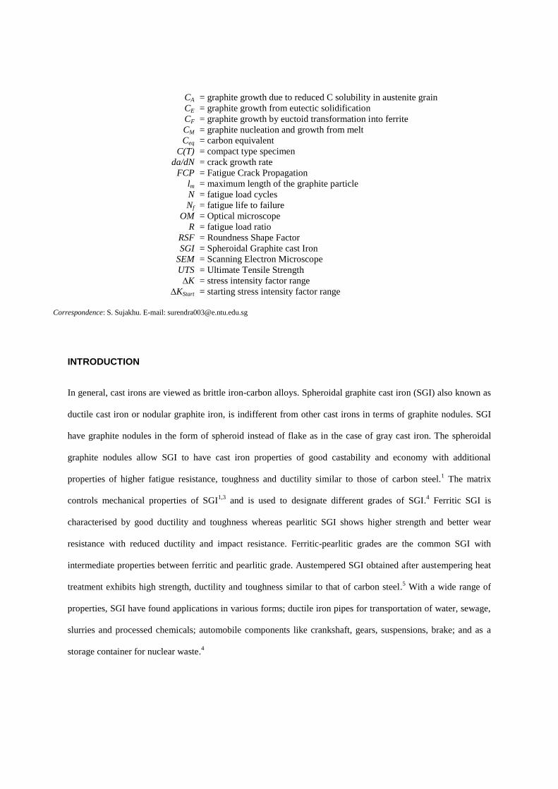
NOMENCLATURE a
A
Am
= crack length
= area of graphite particle
= area of circle of diameter equivalent to the maximum axis length of the
graphite nodule
CA
CE
CF
CM
Ceq
C(T)
da/dN
FCP
lm
N
Nf
OM
R
RSF
SGI
SEM
UTS
∆K
∆KStart
= graphite growth due to reduced C solubility in austenite grain
= graphite growth from eutectic solidification
= graphite growth by euctoid transformation into ferrite
= graphite nucleation and growth from melt
= carbon equivalent
= compact type specimen
= crack growth rate
= Fatigue Crack Propagation
= maximum length of the graphite particle
= fatigue load cycles
= fatigue life to failure
= Optical microscope
= fatigue load ratio
= Roundness Shape Factor
= Spheroidal Graphite cast Iron
= Scanning Electron Microscope
= Ultimate Tensile Strength
= stress intensity factor range
= starting stress intensity factor range
Correspondence: S. Sujakhu. E-mail: [email protected]
INTRODUCTION
In general, cast irons are viewed as brittle iron-carbon alloys. Spheroidal graphite cast iron (SGI) also known as
ductile cast iron or nodular graphite iron, is indifferent from other cast irons in terms of graphite nodules. SGI
have graphite nodules in the form of spheroid instead of flake as in the case of gray cast iron. The spheroidal
graphite nodules allow SGI to have cast iron properties of good castability and economy with additional
properties of higher fatigue resistance, toughness and ductility similar to those of carbon steel.1 The matrix
controls mechanical properties of SGI1,3
and is used to designate different grades of SGI.4 Ferritic SGI is
characterised by good ductility and toughness whereas pearlitic SGI shows higher strength and better wear
resistance with reduced ductility and impact resistance. Ferritic-pearlitic grades are the common SGI with
intermediate properties between ferritic and pearlitic grade. Austempered SGI obtained after austempering heat
treatment exhibits high strength, ductility and toughness similar to that of carbon steel.5 With a wide range of
properties, SGI have found applications in various forms; ductile iron pipes for transportation of water, sewage,
slurries and processed chemicals; automobile components like crankshaft, gears, suspensions, brake; and as a
storage container for nuclear waste.4
Graphite nodules in SGI not only influence mechanical properties, but also play a vital role in fatigue crack
initiation and propagation. Iacoviello et al.6 have summarised graphite nodules as: ‘rigid spheres’ not bonded to
the matrix and acting like voids, ‘crack arresters’ that minimised the stress intensification at the crack tip, and
‘crack closure effect riser’. Many studies2,5-15
have been reported to investigate the fatigue mechanism and the
influence of graphite nodules. Most of them had described graphite nodule-matrix decohesion as one of the most
frequent damaging micromechanism in SGI materials. Studies2,3,5,10,16
had shown the evident influence of the
matrix microstructure and chemical composition on the fatigue resistance of SGI. Effect of stress ratio (R) and
matrix microstructure on crack propagation resistance has been studied by Iacoviello et al.2, who showed
increasing crack growth rate with higher R. Kasvayee et al. studied microcrack initiation mechanism in high
silicon cast iron during tensile loading17
and microstructural strain distribution to explain crack initiation in
SGI.18
Shirani et al.19
and Endo et al.20
studied the effect of casting defects, indicating it as a common damage
initiation point in cast material.
In-situ tensile tests with SEM studies are frequently used methods to investigate damage mechanisms.
Damage mechanisms studies on ferritic SGI2,7,8
stated that ferrite matrix-nodule was not necessarily a
preferential crack path: in fact, the crack could propagate both nearby graphite nodules or by graphite nodule
decohesion. Some secondary cracks were also reported, initiating both at the matrix-nodule interface and ferrite
matrix. Similar studies on pearlitic SGI2,6,21
indicated that fatigue crack grew along ferrite lamella either by
delamination or in a transgranular mechanism with less frequent secondary cracks. Pearlite matrix-nodule
decohesion was reported with internal cracking of graphite nodule into nodule core and nodule shield. Ferritic-
pearlitic SGI crack path was characterized by the presence of many secondary cracks and clear graphite-matrix
decohesion.2,13
A study by Greno et al.5 on austempered SGI described crack propagation by connecting small
cracks emanating from nodules and their growth towards a principal crack.
Ferritic grades have good ductility and toughness whereas pearlitic grades have higher strength and wear
resistance. To obtain combined properties, ferritic-pearlitic grades like EN-GJS-500-7 are considered in many
applications. At higher Si content, casting solidification led to the formation of EN-GJS-500-14 with complete
ferrite matrix. Silicon has a matrix strengthening effect on SGI, which also reduces variation of mechanical
properties. 23
GJS-500-14 has a strength similar to that of GJS-500-7 with a higher ductility. Such high Si SGIs
are capable of replacing higher strength SGI grades, and even some steels. Alhussein et al.24
investigated the
influence of Si content on the mechanical behaviour of ferritic SGI. Out of the investigated materials, GJS-500-
14 showed promising results with significant increase in strength and less reduction in ductility. Understanding
the influence of graphite nodule on fatigue micromechanisms on the high Si SGI is crucial, as its use is
extending to many automobile and wind turbine parts.
Shape and form of graphite nodule have significant effects on crack initiation and propagation behaviour of
SGI. Even if SGI are treated to form spheroidal graphite nodules, other forms of graphite particles may grow
due to the effect of other trace elements, or insufficient addition of inoculant or nodulizer during the
solidification process.25,26
Chunky, compacted, vermicular and irregular graphite nodules are commonly
observed degenerated graphite nodules due to poor treatment of the melt. Other elements like S, F, O, P, N, B
can be found in trace quantity in cast irons. These trace elements in the melt affect graphite nucleation and
growth morphology.26
The effect of these trace elements was divided into three parts; S and B as flake graphite
stabilizer; O and F stabilising compacted or vermicular graphite growth; P and N mostly neutral. . It was
reported that the graphite growth morphology was related to the impurities in the Fe-based liquid.27
Inoculant
and nodulizer are added into the melt to stabilize these trace elements and achieve desired graphite growth
morphology. In SGI, inoculant is added to form micro-particles mostly oxides and sulphides that provide
graphite nucleation sites. Skaland28
reported that oxide and sulphide particles have at least one lattice space
matching graphite lattice space to assist graphite nucleation and growth. It was also reported that MgO particles
were found at the centre of graphite nodules.25,29
The melt is treated with Mg-based nodulizer to control oxides
and sulphides particles and favor spheroidal graphite growth. Mg forms MgO and MgS by dissolving O and S in
the melt. Studies reported easy incorporation of atoms in the a-direction (basal plane in graphite hpc crystal
structure) but with the lower probability of attaching in the c-direction [0 0 0 1] normal to the graphene
monolayer.27
Reported graphite growth direction was along a-direction for flake graphite nodule and along c-
direction for nodular graphite. Compacted or vermicular graphite nodules grew in a complex way and did not
have one preferred growth direction. Muhmond et al.25
have shown that the graphite growth was along the
circumference in SGI and the tentative size of different growth region was reported elsewhere.7 These different
growth regions created property variation within graphite nodules, which caused internal cracking of the
graphite nodules at the interface of different growth regions.22
Graphite form and its growth morphology have
considerable influence on SGI damage mechanisms. So, it is important to include graphite growth morphology
in damage mechanism studies.
In this study, the focus is on high Si EN-GJS-500-14. The aim of this work is to develop a comprehensive
understanding of fatigue damage micromechanisms and the influence of graphite form and its growth
morphology in different fatigue stages. Fatigue crack initiation (FCI) and fatigue crack propagation (FCP) tests
were conducted on miniature tensile and compact tension specimens, which were studied in SEM to observe the
crack path and fracture surface. Base on the observed crack initiation and propagation results, fatigue damage
mechanisms are proposed.
MATERIAL
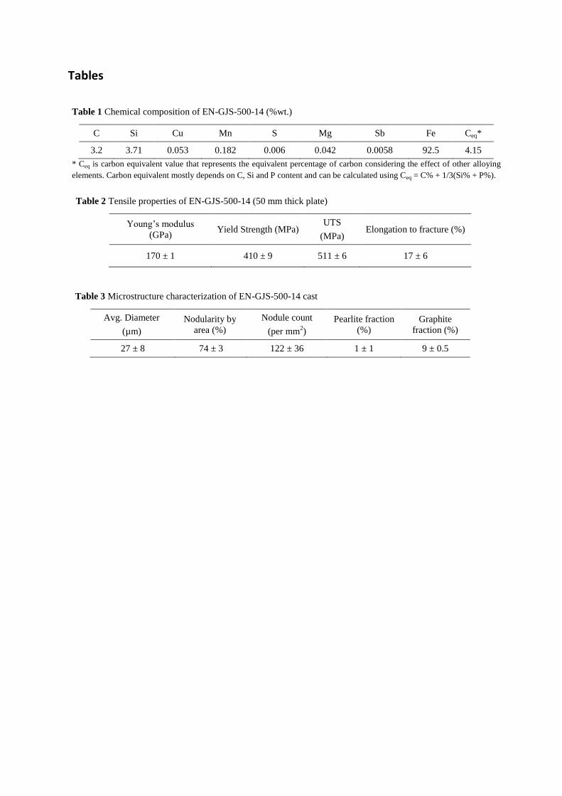
EN-GJS-500-14, a ferritic spheroidal graphite cast iron (SGI) with chemical composition presented in Table
1 was used in this work. The sample material was casted as a 50 mm thick plate. To increase homogeneous
graphite nucleation sites, inoculation process was performed both in ladle and in stream using commercially
available inoculant Foundrisil 67 (64 - 70 % Si, < 1.25 % Al, 0.17 – 1.25 % Ca, 0.75 – 1.25 % Ba and Fe
balance). To favor spheroidal graphite growth morphology, Mg treatment was performed using commercially
available Ce free FeSiMg nodulizer Ceriumfritt (44 - 48 % Si, 5.5 – 6.5 % Mg, < 0.1 % RE, 0.3 – 0.5 % Ca, <
0.7 % Al, < 0.05 % Ce and Fe balance). The combination of inoculation and Mg treatment process was adequate
to produce a majority of spheroidal graphite nodules, but some fraction of graphite nodules were irregular and
compacted as shown in Fig. 1. The tensile properties of the cast material are presented in Table 2. These
properties are comparable with EN-GJS-500-7 which has a ferritic-pearlitic matrix. Microstructure
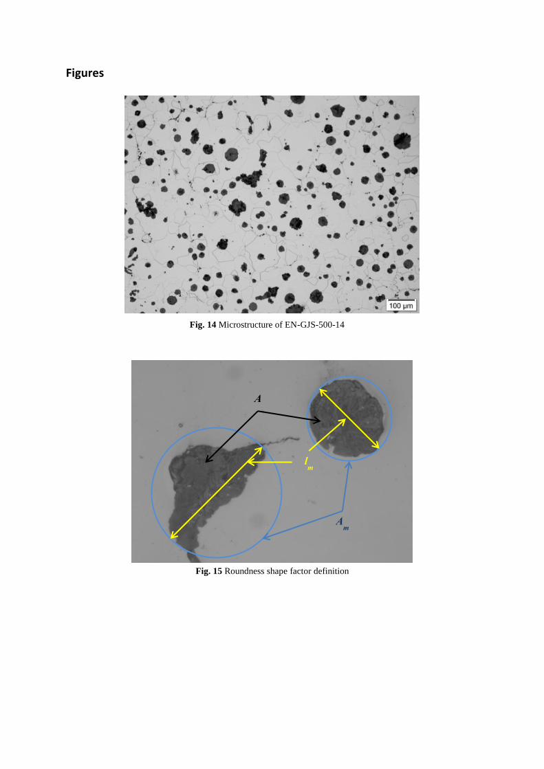
characterization was based on image processing and ASTM standard E2567 was used to evaluate graphite
morphology (size, nodularity and nodule count). To evaluate nodularity of the graphite nodules, roundness
shape factor (RSF) was defined as shown in Fig. 2 and calculated by eq. (1). Average nodularity of the graphite
nodules was evaluated based on area fraction using eq. (2), where graphite nodules were considered nodular if
RSF is greater than 0.6. Around 122 graphite nodules of average diameter 27 µm were observed per mm2 with
an average % nodularity of 74 % as listed in Table 3.
Table 1 Chemical composition of EN-GJS-500-14 (%wt.)
C Si Cu Mn S Mg Sb Fe Ceq*
3.2 3.71 0.053 0.182 0.006 0.042 0.0058 92.5 4.15
* Ceq is carbon equivalent value that represents the equivalent percentage of carbon considering the effect of other alloying
elements. Carbon equivalent mostly depends on C, Si and P content and can be calculated using Ceq = C% + 1/3(Si% + P%).
Table 2 Tensile properties of EN-GJS-500-14 (50 mm thick plate)
Young’s modulus
(GPa) Yield Strength (MPa)
UTS
(MPa) Elongation to fracture (%)
170 ± 1 410 ± 9 511 ± 6 17 ± 6
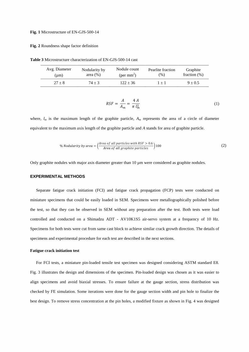
Fig. 1 Microstructure of EN-GJS-500-14
Fig. 2 Roundness shape factor definition
Table 3 Microstructure characterization of EN-GJS-500-14 cast
Avg. Diameter
(µm)
Nodularity by
area (%)
Nodule count
(per mm2)
Pearlite fraction
(%)
Graphite
fraction (%)
27 ± 8 74 ± 3 122 ± 36 1 ± 1 9 ± 0.5
𝑅𝑆𝐹 = 𝐴
𝐴𝑚
= 4 𝐴
𝜋 𝑙𝑚2
(1)
where, lm is the maximum length of the graphite particle, Am represents the area of a circle of diameter
equivalent to the maximum axis length of the graphite particle and A stands for area of graphite particle.
% 𝑁𝑜𝑑𝑢𝑙𝑎𝑟𝑖𝑡𝑦 𝑏𝑦 𝑎𝑟𝑒𝑎 = (𝐴𝑟𝑒𝑎 𝑜𝑓 𝑎𝑙𝑙 𝑝𝑎𝑟𝑡𝑖𝑐𝑙𝑒𝑠 𝑤𝑖𝑡ℎ 𝑅𝑆𝐹 > 0.6
𝐴𝑟𝑒𝑎 𝑜𝑓 𝑎𝑙𝑙 𝑔𝑟𝑎𝑝ℎ𝑖𝑡𝑒 𝑝𝑎𝑟𝑡𝑖𝑐𝑙𝑒𝑠 ) 100 (2)
Only graphite nodules with major axis diameter greater than 10 µm were considered as graphite nodules.
EXPERIMENTAL METHODS
Separate fatigue crack initiation (FCI) and fatigue crack propagation (FCP) tests were conducted on
miniature specimens that could be easily loaded in SEM. Specimens were metallographically polished before
the test, so that they can be observed in SEM without any preparation after the test. Both tests were load
controlled and conducted on a Shimadzu ADT - AV10K1S5 air-servo system at a frequency of 10 Hz.
Specimens for both tests were cut from same cast block to achieve similar crack growth direction. The details of
specimens and experimental procedure for each test are described in the next sections.
Fatigue crack initiation test
For FCI tests, a miniature pin-loaded tensile test specimen was designed considering ASTM standard E8.
Fig. 3 illustrates the design and dimensions of the specimen. Pin-loaded design was chosen as it was easier to
align specimens and avoid biaxial stresses. To ensure failure at the gauge section, stress distribution was
checked by FE simulation. Some iterations were done for the gauge section width and pin hole to finalize the
best design. To remove stress concentration at the pin holes, a modified fixture as shown in Fig. 4 was designed
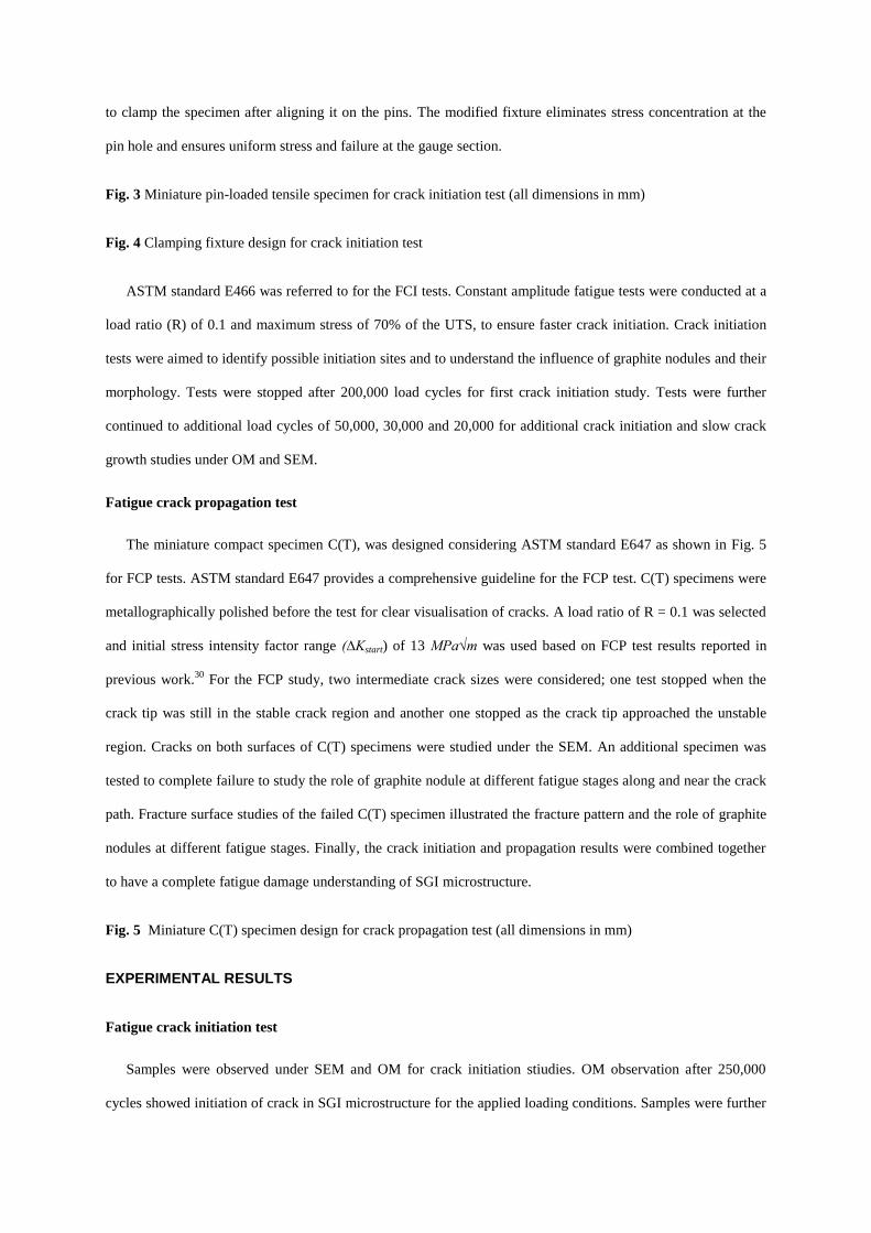
to clamp the specimen after aligning it on the pins. The modified fixture eliminates stress concentration at the
pin hole and ensures uniform stress and failure at the gauge section.
Fig. 3 Miniature pin-loaded tensile specimen for crack initiation test (all dimensions in mm)
Fig. 4 Clamping fixture design for crack initiation test
ASTM standard E466 was referred to for the FCI tests. Constant amplitude fatigue tests were conducted at a
load ratio (R) of 0.1 and maximum stress of 70% of the UTS, to ensure faster crack initiation. Crack initiation
tests were aimed to identify possible initiation sites and to understand the influence of graphite nodules and their
morphology. Tests were stopped after 200,000 load cycles for first crack initiation study. Tests were further
continued to additional load cycles of 50,000, 30,000 and 20,000 for additional crack initiation and slow crack
growth studies under OM and SEM.
Fatigue crack propagation test
The miniature compact specimen C(T), was designed considering ASTM standard E647 as shown in Fig. 5
for FCP tests. ASTM standard E647 provides a comprehensive guideline for the FCP test. C(T) specimens were
metallographically polished before the test for clear visualisation of cracks. A load ratio of R = 0.1 was selected
and initial stress intensity factor range (∆Kstart) of 13 MPa√m was used based on FCP test results reported in
previous work.30
For the FCP study, two intermediate crack sizes were considered; one test stopped when the
crack tip was still in the stable crack region and another one stopped as the crack tip approached the unstable
region. Cracks on both surfaces of C(T) specimens were studied under the SEM. An additional specimen was
tested to complete failure to study the role of graphite nodule at different fatigue stages along and near the crack
path. Fracture surface studies of the failed C(T) specimen illustrated the fracture pattern and the role of graphite
nodules at different fatigue stages. Finally, the crack initiation and propagation results were combined together
to have a complete fatigue damage understanding of SGI microstructure.
Fig. 5 Miniature C(T) specimen design for crack propagation test (all dimensions in mm)
EXPERIMENTAL RESULTS
Fatigue crack initiation test
Samples were observed under SEM and OM for crack initiation stiudies. OM observation after 250,000
cycles showed initiation of crack in SGI microstructure for the applied loading conditions. Samples were further
tested and observed in between the tests to study crack initiation and growth. After around 400,000 cycles, most
of the specimens showed multiple microcrack initiation. Detailed SEM studies were performed at different
intervals and the observed damage initiation mechanisms are illustrated in Fig. 6 to Fig. 10. Damage initiation
mechanisms can be explained in three types based on the point of crack initiation in the microstructure.
Fig. 6 Fatigue damage initiations on face 1 of the miniature FCI specimen(R = 0.1, Smax = 350 MPa, N =
390,000 cycles)
Fig. 7 Fatigue damage initiations on face 2 of the miniature FCI specimen(R = 0.1, Smax = 350 MPa, N =
390,000 cycles)
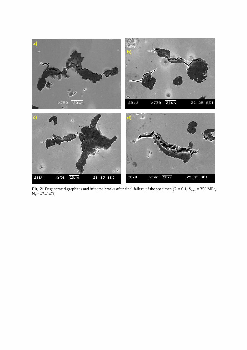
Firstly, cracks were initiated from degenerated graphite nodules. In Fig. 6: a) – d) and Fig. 7: a) – c), cracks
were initiated earlier from compacted or irregular type graphite nodules. The occurrences of these degenerated
graphite nodules were found to be vulnerable from the point of crack initiation, as those graphite nodules
initiated early microcracks. Crack initiation in these graphite nodules were either by internal cracking of
graphite nodule followed by crack growth into the matrix (Fig. 6: b, c, k, m and Fig. 7: c, e, f, l), or by
decohesion followed by crack initiation from the interface (Fig. 6: d, e, f, o and Fig. 7: a, g, j, n), or by the
combination of these mechanisms (Fig. 7: p, q). Graphite nodules with their major axis perpendicular to the
loading direction were preferred initiation sites. The initiated cracks grew perpendicular to the loading direction
and one of these initiated cracks grew as the main crack that led to final failure of the specimen. Other initiated
cracks opened up on final failure (Fig. 8), which clearly illustrates internal cracking of the degenerated graphite
nodules. It should be noted that all the initiated cracks did not show significant growth after the main crack
started to grow.
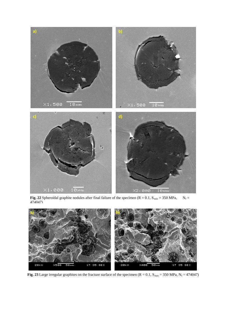
Secondly, internal cracking of spheroidal graphite nodules into onion-like damage were observed. Similar
results were also reported by Di Cocco et al.8 for the in-situ tensile test. As shown in Fig. 6: g) – j) and Fig. 7:
d), h), m), larger graphite nodules tend to internally crack into graphite core and shield. Not all nodular graphite
showed such internal cracking; many were still intact in the ferrite matrix. Comparing the size of graphite
nodules, it can be assumed that those larger nodules might have nucleated earlier in solidification stage, grown
from the melt and then by diffusion of carbon from austenite; causing property difference within each graphite
nodule. The resulting property difference inside the graphite nodule had caused internal cracking of fully grown
spheroidal graphite nodules. Decohesion of graphite/matrix interface was reported as one of the common
damage mechanism in SGI microstructure. Overall, graphite/matrix decohesion played an important role (Fig.
9), but at the point of cracks initiation from degenerated graphite nodules, most of the spheroidal graphite
nodules did not initiated cracks even they were debond from the ferrite matrix. So, graphite/matrix decohesion
was not necessarily the influencing mechanism at early crack initiation, but it was one of the important
mechanisms in crack propagation. On few occasions, cracks were also initiated from graphite/ferrite interface
(Fig. 6: l, q and Fig. 7: o). Such crack initiation was uncommon and mostly the spheroidal graphite nodules were
intact in the ferrite matrix at the early crack initiation stage when the compacted and irregular graphite nodules
already showed sign of initiation.
Lastly, crack initiations were also observed from shrinkage porosities present in the microstructure (Fig. 6: n
and Fig. 7: i, k). Casting defects like shrinkage porosity have been reported as one of the major cause of early
cracks initiation in cast irons.19,20
The casting process for investigated SGI was optimized, so no larger casting
defects were observed, only shrinkages porosities of a size comparable to graphite nodule were observed
occasionally. These shrinkage porosities showed crack initiation at similar fatigue cycles as for the compacted
graphite nodules. Shrinkage porosities were void in the matrix that gave stress concentration effect and cracks
initiated earlier at the edge of the void. Only few such defects were observed in entire gauge section, the
presence of which could initiate early crack depending on the size of the shrinkage defect.
Fig. 7 Degenerated graphites and initiated cracks after final failure of the specimen (R = 0.1, Smax = 350 MPa,
Nf = 474047)
Fig. 8 Spheroidal graphite nodules after final failure of the specimen (R = 0.1, Smax = 350 MPa, Nf = 474047)
Fig. 9 Large irregular graphites on the fracture surface of the specimen (R = 0.1, Smax = 350 MPa, Nf = 474047)
After the crack initiation observations, the specimen was further tested to final failure. The crack in Fig. 6: b)
on face 1 and Fig. 7: q) on face 2 propagated to form the main crack, which grew by connecting initiated cracks
and debonded graphite nodules. Soon after the main crack started to grow, the specimen fractured and could not
provide details on propagation mechanisms. Therefore, to clearly understand crack propagation
micromechanisms separate FCP tests were conducted on miniature C(T) specimens. From the crack initiation
study, it was difficult to predict which crack among those initiated would result into final failure, but it could be
conjectured that one of the cracks initiated from larger defect (casting defects or degenerated graphite nodules)
would further propagate. Fig. 6 and 7 also indicate roundness shape factor (RSF) for the graphite nodules
initiating damage. Mostly the graphite nodules with lower RSF values initiate early cracks whereas the graphite
nodules with RSF values higher than 0.9 showed internal cracking and decohesion mechanisms. Fig. 8 and 9
show the state of the graphite nodules after final failure. Quantitative analysis of damage initiation was reported
in previous study.31
Results showed that graphite nodule decohesion was dominant mechanism for spheroidal
graphite nodules, whereas compacted graphite nodules initiated cracks mostly by combined decohesion and
internal cracking. Cracks that initiated in compacted graphite nodules opened up without significant growth in
crack size (Fig. 8). Spheroidal graphite particles (Fig. 9) after final failure shows an increase in decohesion gap
with clear view of circumferential internal crack. The fracture surface study showed the presence of large
irregular graphite particles along the crack path (Fig. 10). Such embedded irregular graphite particles have a
significant influence on primary crack propagation and final fracture of the SGI components. Larger submerged
defects could initiate secondary cracks and form crack branch, indicating complex nature of crack propagation
in SGI microstructure.
Fatigue crack propagation test
The SEM results of short and long crack studies in FCP tests are presented in Fig. 11 and 12 respectively.
For short crack, FCP test was stopped after 61,000 cycles; whereas for long crack, test was stopped after 97,000
cycles. Usually, multiple crack initiations were observed at the notch (Fig. 11: a) and Fig. 12: a), d)) but only
one crack further propagated, other cracks were arrested within the ferrite matrix or at the graphite nodule.
Dominant growth of the main crack gave insight on the fatigue crack propagation mechanism without influence
of other cracks. The primary crack propagated towards neighboring graphite nodules and connecting most of
them to the crack path. Such crack growth led to a zigzag crack path which was also reported in previous
works.2,7,8
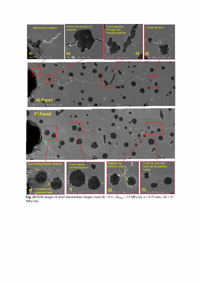
Fig. 10 SEM images of short intermediate fatigue crack (R = 0.1, ∆KStart = 13 MPa√m, a = 0.75 mm, ∆K = 27
MPa√m)
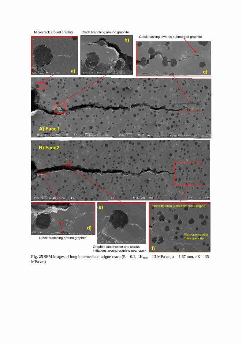
Fig. 11 SEM images of long intermediate fatigue crack (R = 0.1, ∆KStart = 13 MPa√m, a = 1.67 mm, ∆K = 35
MPa√m)
Graphite/ferrite interface decohesion is considered as one of the frequent damage mechanism in SGI iron,
which was clearly visualised in many occasions. Partial decohesion of spheroidal graphite particles took shorter
path toward next graphite nodule (Fig. 11: b), e), f)). Such partial decohesion seemed to provide crack tip
blunting effect that stopped further crack propagation for a short time. In case of multiple cracks initiation at the
notch, some cracks were completely arrested at the graphite nodule, which highlighted graphite nodule as
possible crack arrester. In Fig. 11: h) similar phenomenon was observed, where the crack tip just reached a
graphite nodule that stopped crack propagation. After additional cycles, the arrested crack further propagated
into the ferrite matrix until it reached next graphite nodule. This type of graphite decohesion left partially
embedded graphite nodule on fracture surface. Many such partially debonded types of graphite nodules were
observed along the crack paths in Fig. 11 and 12.
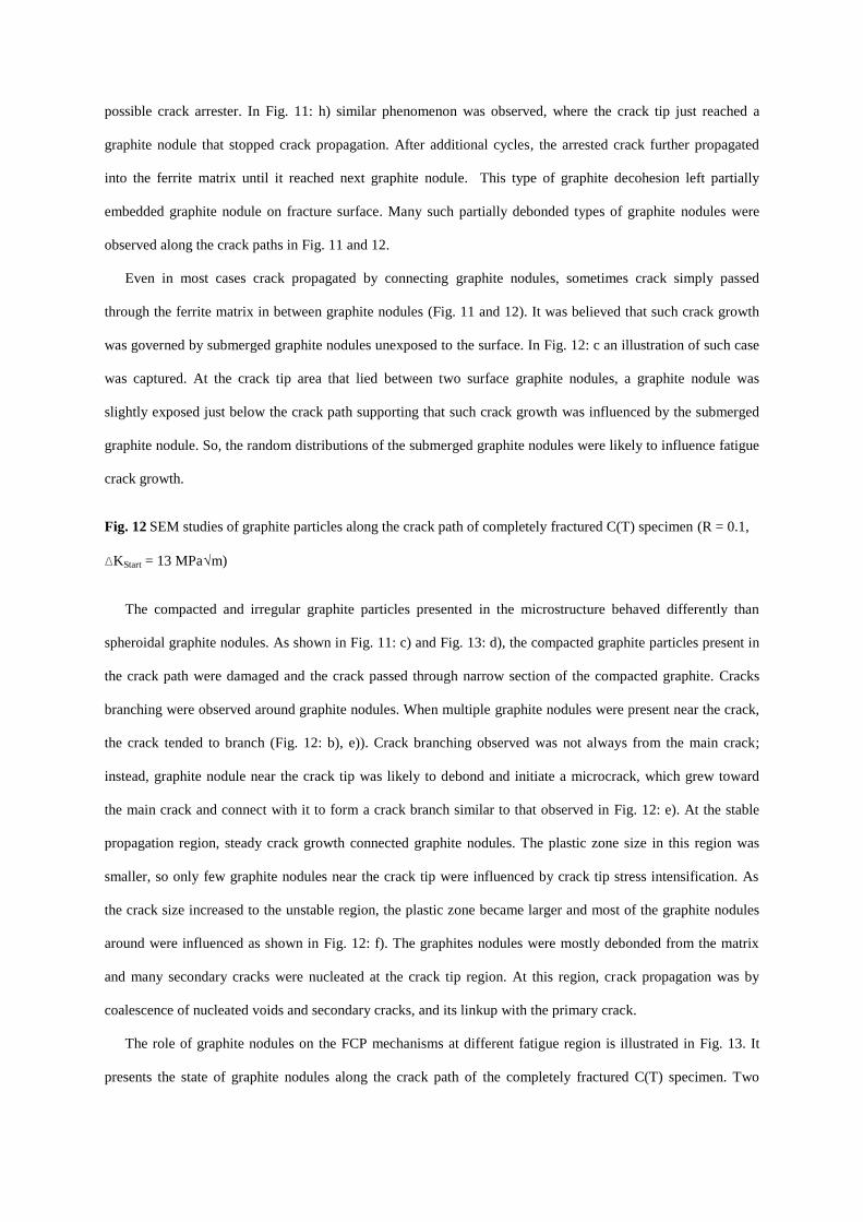
Even in most cases crack propagated by connecting graphite nodules, sometimes crack simply passed
through the ferrite matrix in between graphite nodules (Fig. 11 and 12). It was believed that such crack growth
was governed by submerged graphite nodules unexposed to the surface. In Fig. 12: c an illustration of such case
was captured. At the crack tip area that lied between two surface graphite nodules, a graphite nodule was
slightly exposed just below the crack path supporting that such crack growth was influenced by the submerged
graphite nodule. So, the random distributions of the submerged graphite nodules were likely to influence fatigue
crack growth.
Fig. 12 SEM studies of graphite particles along the crack path of completely fractured C(T) specimen (R = 0.1,
∆KStart = 13 MPa√m)
The compacted and irregular graphite particles presented in the microstructure behaved differently than
spheroidal graphite nodules. As shown in Fig. 11: c) and Fig. 13: d), the compacted graphite particles present in
the crack path were damaged and the crack passed through narrow section of the compacted graphite. Cracks
branching were observed around graphite nodules. When multiple graphite nodules were present near the crack,
the crack tended to branch (Fig. 12: b), e)). Crack branching observed was not always from the main crack;
instead, graphite nodule near the crack tip was likely to debond and initiate a microcrack, which grew toward
the main crack and connect with it to form a crack branch similar to that observed in Fig. 12: e). At the stable
propagation region, steady crack growth connected graphite nodules. The plastic zone size in this region was
smaller, so only few graphite nodules near the crack tip were influenced by crack tip stress intensification. As
the crack size increased to the unstable region, the plastic zone became larger and most of the graphite nodules
around were influenced as shown in Fig. 12: f). The graphites nodules were mostly debonded from the matrix
and many secondary cracks were nucleated at the crack tip region. At this region, crack propagation was by
coalescence of nucleated voids and secondary cracks, and its linkup with the primary crack.
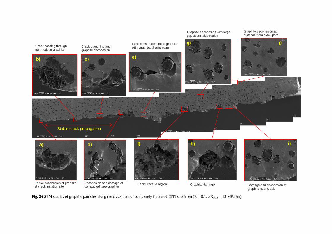
The role of graphite nodules on the FCP mechanisms at different fatigue region is illustrated in Fig. 13. It
presents the state of graphite nodules along the crack path of the completely fractured C(T) specimen. Two
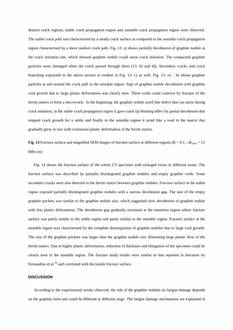
distinct crack regions; stable crack propagation region and unstable crack propagation region were observed.
The stable crack path was characterised by a steady crack surface as compared to the unstable crack propagation
region characterised by a more random crack path. Fig. 13: a) shows partially decohesion of graphite nodule at
the crack initiation site, which showed graphite nodule could assist crack initiation. The compacted graphite
particles were damaged when the crack passed through them (13: b) and d)). Secondary cracks and crack
branching explained in the above section is evident in Fig. 13: c) as well. Fig. 13: e) – h) shows graphite
particles at and around the crack path in the unstable region. Sign of graphite nodule decohesion with graphite
void growth due to large plastic deformation was clearly seen. These voids could coalesce by fracture of the
ferrite matrix to form a microcrack. In the beginning, the graphite nodule acted like defect that can assist during
crack initiation, in the stable crack propagation region it gave crack tip blunting effect by partial decohesion that
stopped crack growth for a while and finally in the unstable region it acted like a void in the matrix that
gradually grew in size with continuous plastic deformation of the ferrite matrix.
Fig. 13 Fracture surface and magnified SEM images of fracture surface at different regions (R = 0.1, ∆KStart = 13
MPa√m)
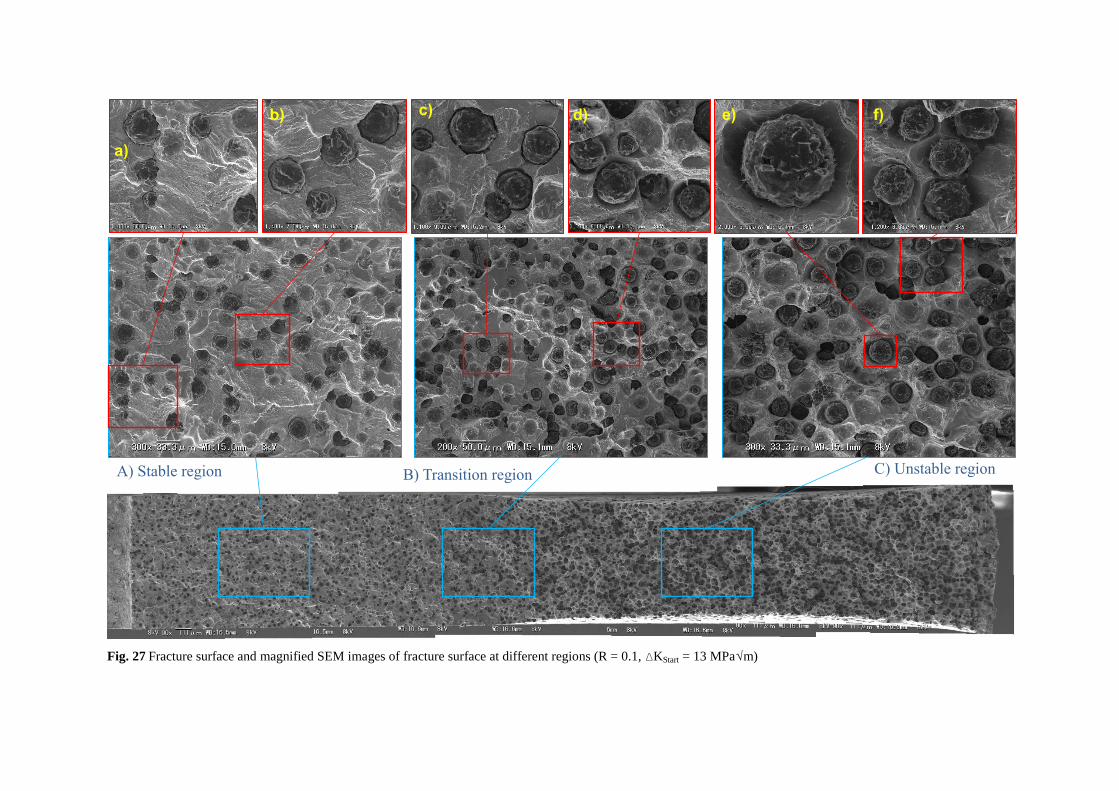
Fig. 14 shows the fracture surface of the whole CT specimen with enlarged views in different zones. The
fracture surface was described by partially disintegrated graphite nodules and empty graphite voids. Some
secondary cracks were also detected in the ferrite matrix between graphite nodules. Fracture surface in the stable
region exposed partially disintegrated graphite nodules with a narrow decohesion gap. The size of the empty
graphite pockets was similar to the graphite nodule size, which suggested slow decohesion of graphite nodule
with less plastic deformation. The decohesion gap gradually increased at the transition region where fracture
surface was partly similar to the stable region and partly similar to the unstable region. Fracture surface at the
unstable region was characterised by the complete disintegration of graphite nodules due to large void growth.
The size of the graphite pockets was larger than the graphite nodule size illustrating large plastic flow of the
ferrite matrix. Due to higher plastic deformation, reduction of thickness and elongation of the specimen could be
clearly seen in the unstable region. The fracture study results were similar to that reported in literature by
Fernandino et al.36
and correlated with the tensile fracture surface.
DISCUSSION
According to the experimental results observed, the role of the graphite nodules on fatigue damage depends
on the graphite form and could be different at different stage. The fatigue damage mechanisms are explained in

three fatigue stages, namely; crack initiation and tiny crack growth (stage I), stable crack growth (stage II) and
rapid unstable crack growth (stage III).
Stage I – Fatigue crack initiation and tiny crack growth
Based on fatigue damage initiation theory, crack initiation under cyclic load is due to the formation of
irreversible dislocations, its accumulation to develop slip steps and slip bands, which act as possible crack
initiation sites.32
In SGI, the presence of different forms of graphite nodules and casting defects cause
inhomogeneous strain and stress distribution. Strain localisation was reported around graphite nodules that led to
microcrack initiation.17
Such strain localisation was highly dependent on the shape and size of the graphite
nodule and defect. Roundness shape factor was evaluated for all the graphite nodules that showed some sort of
damage (Fig. 6 and 7). The graphite nodules showed two distinct damage initiation mechanisms. Even most of
the graphite nodules were spheroidal; a small fraction was compacted and irregular with lower RSF values.
Mostly, the graphite nodules with RSF less than 0.5 and perpendicular to the loading direction initiated fatigue
microcracks. Most of the spheroidal graphite nodules were still intact at the time of early crack initiation from
degenerated graphite nodules. Greno et al.5 had reported that the graphite nodules were not perfect spheres of
flat surface; instead, the graphite/matrix interface was extremely irregular, which could also be observed in the
fracture surface (Fig. 14). This irregular interface provided stronger bonding to resist graphite-ferrite
decohesion.
The compacted graphite particles with RSF less than 0.5 showed internal cracking that further grew into the
ferrite matrix to form microcracks. This type of graphite growth was mostly along the a-direction (basal plane)
in the hcp lattice structure of the graphene layer. It was reported that the bonding between the basal planes or
graphene layers were weak during graphite growth.33
This weak bonding and soft nature of the graphite
nucleated from melt might be weaker than the interface bond resulting into graphite internal cracking. The
elongated shape of these graphite particles developed higher stress concentration than spheroidal graphite
nodules that contributed to crack growth into the ferrite matrix (Fig. 6, 7 and 8).
The damage of spheroidal graphite nodules was different from that of compacted graphite particles. Most of
the averaged sized graphite nodules were not affected during the early crack initiation stage as the rough
graphite/matrix bonding was strong enough to resist stress localisation around the spheroidal graphite nodules.
Larger spheroidal graphite noduless showed internal cracking into ring and core (Fig. 6, 7 and 8). These fully
grown graphite nodules corresponded to graphite nucleation and growth from melt (CM), growth from eutectic
solidification (CE), growth due to reduced C solubility in austenite grain (CA) and growth by eutectoid
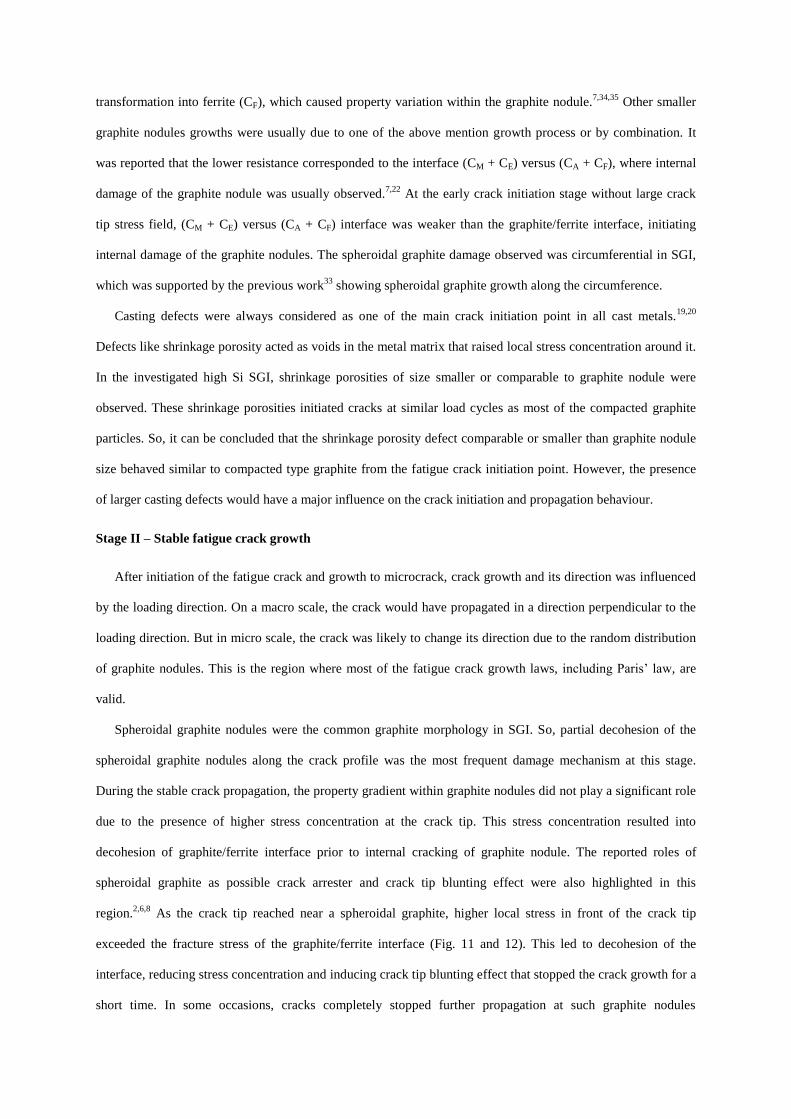
transformation into ferrite (CF), which caused property variation within the graphite nodule.7,34,35
Other smaller
graphite nodules growths were usually due to one of the above mention growth process or by combination. It
was reported that the lower resistance corresponded to the interface (CM + CE) versus (CA + CF), where internal
damage of the graphite nodule was usually observed.7,22
At the early crack initiation stage without large crack
tip stress field, (CM + CE) versus (CA + CF) interface was weaker than the graphite/ferrite interface, initiating
internal damage of the graphite nodules. The spheroidal graphite damage observed was circumferential in SGI,
which was supported by the previous work33
showing spheroidal graphite growth along the circumference.
Casting defects were always considered as one of the main crack initiation point in all cast metals.19,20
Defects like shrinkage porosity acted as voids in the metal matrix that raised local stress concentration around it.
In the investigated high Si SGI, shrinkage porosities of size smaller or comparable to graphite nodule were
observed. These shrinkage porosities initiated cracks at similar load cycles as most of the compacted graphite
particles. So, it can be concluded that the shrinkage porosity defect comparable or smaller than graphite nodule
size behaved similar to compacted type graphite from the fatigue crack initiation point. However, the presence
of larger casting defects would have a major influence on the crack initiation and propagation behaviour.
Stage II – Stable fatigue crack growth
After initiation of the fatigue crack and growth to microcrack, crack growth and its direction was influenced
by the loading direction. On a macro scale, the crack would have propagated in a direction perpendicular to the
loading direction. But in micro scale, the crack was likely to change its direction due to the random distribution
of graphite nodules. This is the region where most of the fatigue crack growth laws, including Paris’ law, are
valid.
Spheroidal graphite nodules were the common graphite morphology in SGI. So, partial decohesion of the
spheroidal graphite nodules along the crack profile was the most frequent damage mechanism at this stage.
During the stable crack propagation, the property gradient within graphite nodules did not play a significant role
due to the presence of higher stress concentration at the crack tip. This stress concentration resulted into
decohesion of graphite/ferrite interface prior to internal cracking of graphite nodule. The reported roles of
spheroidal graphite as possible crack arrester and crack tip blunting effect were also highlighted in this
region.2,6,8
As the crack tip reached near a spheroidal graphite, higher local stress in front of the crack tip
exceeded the fracture stress of the graphite/ferrite interface (Fig. 11 and 12). This led to decohesion of the
interface, reducing stress concentration and inducing crack tip blunting effect that stopped the crack growth for a
short time. In some occasions, cracks completely stopped further propagation at such graphite nodules
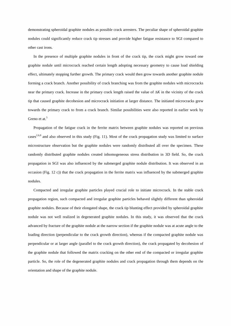
demonstrating spheroidal graphite nodules as possible crack arresters. The peculiar shape of spheroidal graphite
nodules could significantly reduce crack tip stresses and provide higher fatigue resistance to SGI compared to
other cast irons.
In the presence of multiple graphite nodules in front of the crack tip, the crack might grow toward one
graphite nodule until microcrack reached certain length adopting necessary geometry to cause load shielding
effect, ultimately stopping further growth. The primary crack would then grow towards another graphite nodule
forming a crack branch. Another possibility of crack branching was from the graphite nodules with microcracks
near the primary crack. Increase in the primary crack length raised the value of ∆K in the vicinity of the crack
tip that caused graphite decohesion and microcrack initiation at larger distance. The initiated microcracks grew
towards the primary crack to from a crack branch. Similar possibilities were also reported in earlier work by
Greno et at.5
Propagation of the fatigue crack in the ferrite matrix between graphite nodules was reported on previous
cases2,6,8
and also observed in this study (Fig. 11). Most of the crack propagation study was limited to surface
microstructure observation but the graphite nodules were randomly distributed all over the specimen. These
randomly distributed graphite nodules created inhomogeneous stress distribution in 3D field. So, the crack
propagation in SGI was also influenced by the submerged graphite nodule distribution. It was observed in an
occasion (Fig. 12 c)) that the crack propagation in the ferrite matrix was influenced by the submerged graphite
nodules.
Compacted and irregular graphite particles played crucial role to initiate microcrack. In the stable crack
propagation region, such compacted and irregular graphite particles behaved slightly different than spheroidal
graphite nodules. Because of their elongated shape, the crack tip blunting effect provided by spheroidal graphite
nodule was not well realized in degenerated graphite nodules. In this study, it was observed that the crack
advanced by fracture of the graphite nodule at the narrow section if the graphite nodule was at acute angle to the
loading direction (perpendicular to the crack growth direction), whereas if the compacted graphite nodule was
perpendicular or at larger angle (parallel to the crack growth direction), the crack propagated by decohesion of
the graphite nodule that followed the matrix cracking on the other end of the compacted or irregular graphite
particle. So, the role of the degenerated graphite nodules and crack propagation through them depends on the
orientation and shape of the graphite nodule.
Stage III - Rapid unstable crack growth
Further growth of crack into the unstable region led to an increased ∆K on the remaining section by
redistribution of the applied load, so that the crack tip stress field extended to a larger area. The matrix alone
was no longer able to sustain the load causing large plastic flow of the matrix that caused decohesion of graphite
nodules creating large voids. Here, the graphite nodules acted like void defects after decohesion and initiated
multiple microcracks. Then the final failure was by growth and coalescence of the graphite voids and initiated
microcracks causing unstable crack propagation. The failure mechanism and the role of graphite nodule at this
stage showed similarities to rapid fracture in tensile test.
CONCLUSION
Fatigue damage mechanisms in high Si SGI were investigated based on the FCI and FCP tests. On the basis
of the experimental results, following conclusions can be made:
Cracks initiation in high Si SGI was mostly from degenerated graphite nodules and casting defects.
Degenerated graphite nodules with RSF less than 0.5 initiated cracks either by internal cracking of the graphite
nodules followed by cracks initiation into the matrix; or by graphite nodules decohesion followed by cracks
initiation; or by combination of these mechanisms. However, all the graphite particles with RSF values less
than 0.5 did not initiated cracks as the initiation was also affected by orientation and shape of the graphite
particles. Graphite nodules with RSF higher than 0.5 mostly showed graphite nodules decohesion, spheroidal
graphite nodules with RSF higher than 0.9 in specific did not initiated early cracks. Instead, the larger
spheroidal graphite nodules showed circumferential internal cracking and graphite/ferrite decohesion.
Shrinkage porosities smaller or size comparable to that of the graphite nodules had similar crack initiation
effect as degenerated graphite nodules.
Spheroidal graphite/ferrite matrix interface decohesion was a frequently observed damage mechanism for
crack propagation. Decohesion of spheroidal graphite nodules from the ferrite matrix provided crack tip
blunting effect that stopped propagation for few additional load cycles. However, the crack tip blunting effect
and crack growth depends on RSF. Spheroidal graphite nodules with higher RSF showed clear decohesion,
whereas degenerated graphites with lower RSF were either fractured (perpendicular to the crack growth
direction) or decohesion followed by the matrix cracking (parallel to the crack growth direction). Crack often
formed branches when a crack initiated from the graphite nodules near the crack tip and propagated towards
the primary crack, or in the presence of multiple graphite nodules in front of the crack tip.
The graphite nodules in the unstable region behaved like voids in the ferrite after decohesion. Irrespective of
the RSF values, these voids grew due to plastic flow of the ferrite matrix and coalescence to form microcracks.
Rapid propagation of the main crack by connecting initiated microcracks led to final fracture of the specimen.
This study provided comprehensive understanding of fatigue damage micromechanisms in SGI. Graphite
nodules being important phase in SGI microstructure, the roles played by graphite nodules on damage
mechanism is investigated based on the RSF. It was shown that graphite morphology plays vital role in fatigue
damage micromechanism of SGI and the role could be different at different fatigue stage. The damage
mechanism understanding comes handy in an attempt to optimize SGI microstructure for better fatigue behavior
and would be very useful in an effort to model SGI microstructure for failure prediction.
ACKNOWLEDGEMENT
This work was supported by the Singapore Ministry of Education (MOE) Academic Research Funding
(AcRF) Tier 1 Grand RG26/12. The authors wish to acknowledge financial support by JASSO for TiROP
exchange program in Tokyo Institute of Technology and CompCAST project (2010280) funded by the
Knowledge Foundation in Sweden.
REFERENCE
1 Labrecque C, Gagné M (1998) Review ductile iron: fifty years of continuous development. Can. Metall. Quart. 37: 343-
378.
2 Iacoviello F, Cocco VD, Cavallini M (2010) Ductile cast irons: microstructure influence on fatigue crack propagation
resistance. Frattura ed Integritá Strutturale. 3-16.
3 Gonzaga RA (2013) Influence of ferrite and pearlite content on mechanical properties of ductile cast irons. Mater. Sci.
and Eng., A. 567: 1-8.
4 Jeckins LR, Forrest RD (1993) Properties and selection: Iron, Steel and High performance alloys. ASM Handbook. 10
edn. American Society for Metals, Metals Park, Ohio,, 3-56.
5 Greno GL, Otegui JL, Boeri RE (1999) Mechanisms of fatigue crack growth in Austempered Ductile Iron. Int. J.
Fatigue. 21: 35-43.
6 Iacoviello F, Di Cocco V, Rossi A, Cavallini M (2013) Pearlitic ductile cast iron: damaging micromechanisms at crack
tip. Frattura ed Integrita Strutturale. 25: 102-108.
7 Di Cocco V, Iacoviello F, Ross A, cavallini M, Natali S (2013) Graphite nodules and fatigue crack propagation
micromechanisms in a ferritic ductile cast iron. Fatigue Fract. Engng Mater. Struct. 36: 893.
8 Di Cocco V, Iacoviello F, Rossi A, Iacoviello D (2014) Macro and microscopical approach to the damaging
micromechanisms analysis in a ferritic ductile cast iron. Theor. Appl. Fract. Mec. 69: 26-33.
9 Dong MJ, Prioul C, François D (1997) Damage effect on the fracture toughness of nodular cast iron: Part I. Damage
characterization and plastic flow stress modeling. Metall. Mat. Trans., A. 28: 2245-2254.
10 Tokaji K, Ogawa T, Shamoto K (1994) Fatigue crack propagation in spheroidal-graphite cast irons with different
microstructures. Int. J. Fatigue. 16: 344-350.
11 Zambrano HR, Härkegärd G, Stärk KF (2012) Fracture toughness and growth of short and long fatigue cracks in ductile
cast iron EN-GJS-400-18-LT. Fatigue Fract. Engng Mater. Struct. 35: 374-388.
12 Martínez RA (2010) Fracture surfaces and the associated failure mechanisms in ductile iron with different matrices and
load bearing. Eng. Fract. Mech. 77: 2749-2762.
13 Iacoviello F, Di Cocco V, Cavallini M (2016) Fatigue crack propagation and overload damaging micromechanisms in a
ferritic-pearlitic ductile cast iron. Fatigue Fract. Engng Mater. Struct. 39: 999.
14 Marrow TJ, Çetinel H, Al-Zalmah M, MacDonald S, Withers PJ, Walton J (2000) Short fatigue cracks in austempered
ductile cast iron (ADI). Fatigue Fract. Engng Mater. Struct. 23: 425-434.
15 Marrow TJ, Çetinel H, Al-Zalmah M, MacDonald S, Withers PJ, Walton J (2002) Fatigue crack nuclei in austempered
ductile cast iron. Fatigue Fract. Engng Mater. Struct. 25: 635.
16 Griswold Jr FD, Stephens RI (1987) Comparison of fatigue properties of nodular cast iron production and Y-block
castings. Int. J. Fatigue.9: 3-10.
17 Kasvayee KA, Ghassemali E, Jarfors AEW (2015) Micro-Crack initiation in high-silicon cast iron during tension loadin.
TMS2015, 947-953.
18 Kasvayee KA, Salomonsson K, Ghassemali E, Jarfors AEW (2016) Microstructural strain distribution in ductile iron;
comparison between finite element simulation and digital image correlation measurements. Mater. Sci. and Eng., A. 655:
27-35.
19 Shirani M, Härkegård G (2011) Casting defects and fatigue behaviour of ductile cast iron for wind turbine components:
A comprehensive study Materialwissenschaft und Werkstofftechnik. 42: 1059-1074.
20 Endo M, Yanase K (2014) Effects of small defects, matrix structures and loading conditions on the fatigue strength of
ductile cast irons. Theor. Appl. Fract. Mec. 69: 34-43.
21 Iacoviello F, Di Cocco V, Rossi A, Cavallini M (2015) Fatigue crack tip damaging micromechanisms in pearlitic ductile
cast irons. Fatigue Fract. Engng Mater. Struct. 38: 238-245.
22 Cocco VD, Iacoviello F, Rossi A, Cavallini M, Natali S, Ecarla F (2013) Mechanical properties gradient in graphite
nodules: influence on ferritic DCI damaging micromechanisms. Acta Fract. Roma, Italia, 222–230.
23 Matsushita T, Ghassemali E, Saro AG, Elmquist L, Jarfors AEW (2015) On Thermal Expansion and Density of CGI and
SCI Cast Irons. Metals. 5: 1000-1019.
24 Alhussein A, Risbet M, Bastien A, Chobaut JP, Balloy D, Favergeon J (2014) Influence of silicon and addition elements
on the mechanical behavior of ferritic ductile cast iron. Mater. Sci. and Eng., A. 605: 222-228.
25 Muhmond HM, Fredriksson H (2014) Graphite Growth Morphologies in Cast Iron. Mater. Sci. forum. 790: 458-463.
26 Muhmond HM, Fredriksson H (2014) Relationship Between the Trace Elements and Graphite Growth Morphologies in
Cast Iron. Metall. Mat. Trans., A. 45: 6187-6199.
27 Double DD, Hellawell A (1995) The nucleation and growth of graphite—the modification of cast iron. Acta Metall.
Mater. 43: 2435-2442.
28 Skaland T (2003) Ductile iron shrinkage control through graphite nucleation and growth. Int. J. Cast Met. Res. 16: 11.
29 Igarashi Y, Okada S (1998) Observation and Analysis of the Nucleus of Spheroidal Graphite in Magnesium Treated
Ductile Iron. Int. J. Cast Met. Res. 11: 83-88.
30 Čanžar P, Tonković Z, Kodvanj J (2012) Microstructure influence on fatigue behaviour of nodular cast iron. Mater. Sci.
and Eng., A. 556: 88-99.
31 Sujakhu S, Castagne S, Sakaguchi M, Kasvayee KA, Ghassemali E, Jarfors AEW, Wang W (2017) Micromechanisms
Investigation on Fatigue Crack Initiation and Propagation in High Silicon Spheroidal Graphite Cast Iron. Proceeding of
8th Low Cycle Fatigue Conference, June 27 – 29, Dresden, Germany.
32 Bhat S, Patibandla R (2011) Metal Fatigue and Basic Theoritical Models: A Review. Alloy Steel - Properties and Use,
203-236.
33 Muhmond HM (2014) On the Inoculation and Graphite Morphologies of Cast Iron. Ph.D. dissertation, Dept. Mat. Sci.
Eng. Royal Institute of Technology, Stockholm, Sweden.
34 Pradhan SK, Nayak BB, Sahay SS, Mishra BK (2009) Mechanical properties of graphite flakes and spherulites measured
by nanoindentation. Carbon. 47: 2290-2292.
35 Randall NX, Vandamme M, Ulm F-J (2009) Nanoindentation analysis as a two-dimensional tool for mapping the
mechanical properties of complex surfaces. J. Mater. Res. 24: 11.
36 Fernandino DO, Boeri R (2015) Study of the fracture of ferritic ductile cast iron under different loading conditions.
Fatigue Fract. Engng Mater. Struct. 38: 610-620.
Figures
Fig. 14 Microstructure of EN-GJS-500-14
Am
A
lm
Fig. 15 Roundness shape factor definition
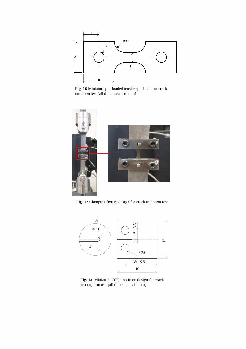
Fig. 16 Miniature pin-loaded tensile specimen for crack
initiation test (all dimensions in mm)
Fig. 17 Clamping fixture design for crack initiation test
10
3.5
ᶲ 2.0
4
R0.1
12
A
A
W=8.5
Fig. 18 Miniature C(T) specimen design for crack
propagation test (all dimensions in mm)
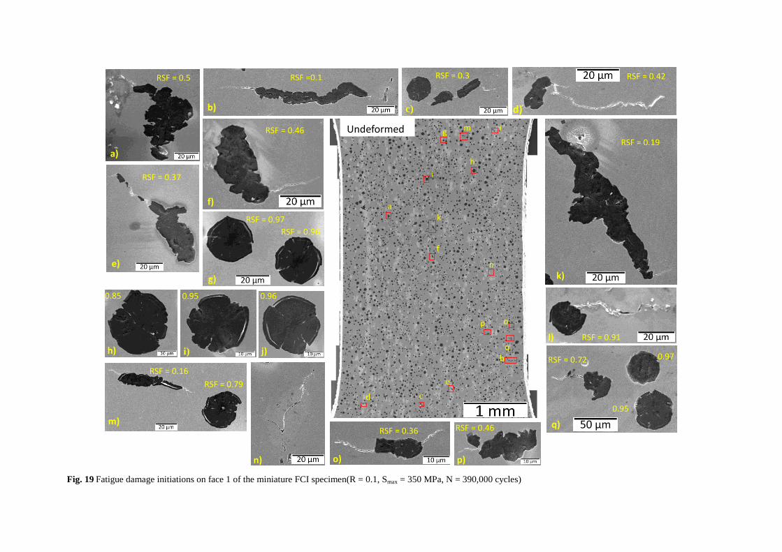
Fig. 19 Fatigue damage initiations on face 1 of the miniature FCI specimen(R = 0.1, Smax = 350 MPa, N = 390,000 cycles)
a
b
c d
h
i
f
k
p o
e
g m l
n
q
a)
b)
RSF =0.1
c)
RSF = 0.3
g)
RSF = 0.97
RSF = 0.96
d)
RSF = 0.42
e)
RSF = 0.37
f)
RSF = 0.46
h)
0.85
i)
0.95
j)
0.96
k)
RSF = 0.19
l) RSF = 0.91
m)
RSF = 0.16
RSF = 0.79
n) o)
RSF = 0.36
p)
RSF = 0.46 q)
RSF = 0.72 0.97
0.95
RSF = 0.5
Undeformed
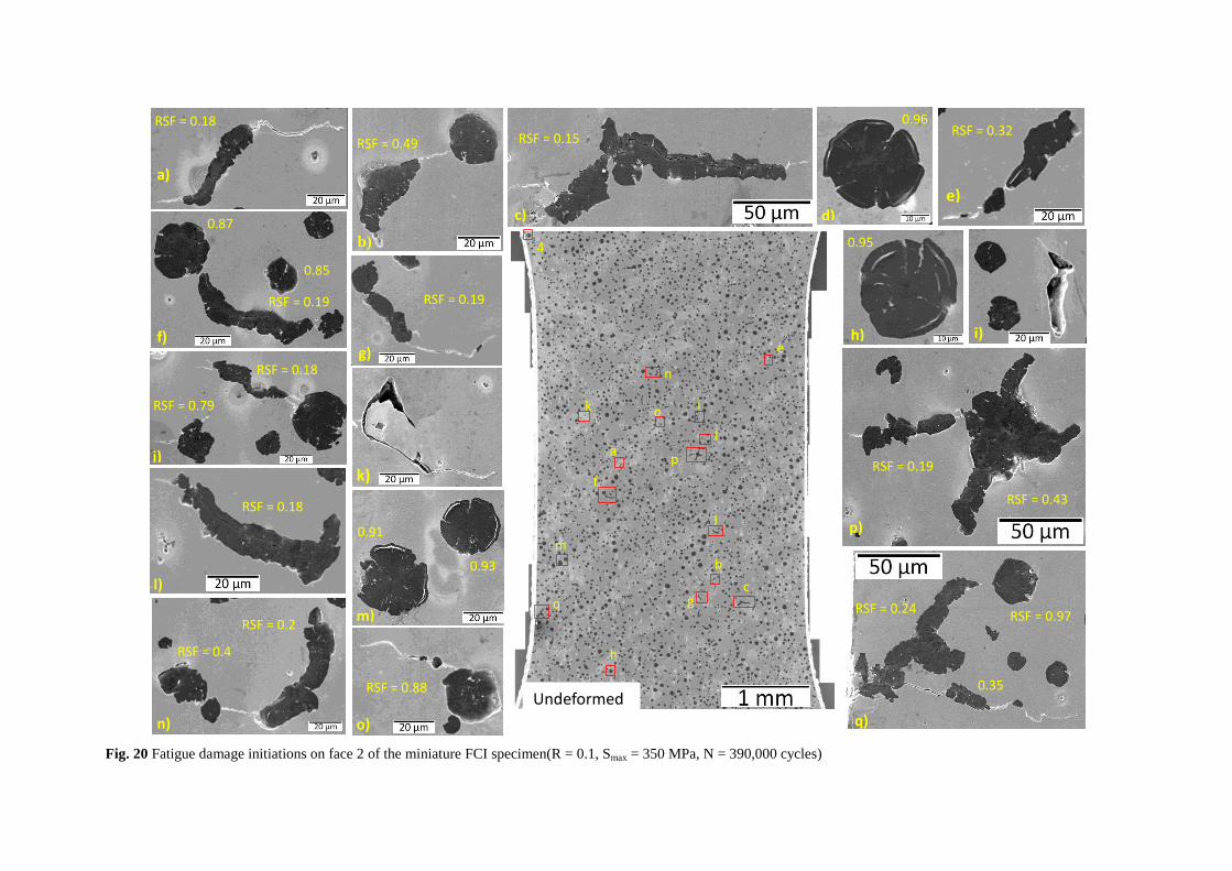
Fig. 20 Fatigue damage initiations on face 2 of the miniature FCI specimen(R = 0.1, Smax = 350 MPa, N = 390,000 cycles)
a
b
c
4
e
p
f
l
q
m
g
n
k o
j
h
i
Undeformed
d)
0.96
c)
RSF = 0.15
a)
RSF = 0.18
b)
RSF = 0.49
h)
0.95
8
e)
RSF = 0.32
f)
RSF = 0.19
0.87
0.85
g)
RSF = 0.19
j)
RSF = 0.79
RSF = 0.18
p)
RSF = 0.19
RSF = 0.43
l)
RSF = 0.18
q)
RSF = 0.24
0.35
RSF = 0.97
n)
RSF = 0.4
RSF = 0.2
o)
RSF = 0.88
k)
m)
0.91
0.93
i)
a)
b)
d) c)
Fig. 21 Degenerated graphites and initiated cracks after final failure of the specimen (R = 0.1, Smax = 350 MPa,
Nf = 474047)
a) b)
d) c)
Fig. 22 Spheroidal graphite nodules after final failure of the specimen (R = 0.1, Smax = 350 MPa, Nf =
474047)
a) b)
Fig. 23 Large irregular graphites on the fracture surface of the specimen (R = 0.1, Smax = 350 MPa, Nf = 474047)
Microcrack initiation Partial decohesion of graphite
Crack passing through non nodular graphite
Crack tip area
A) Face1
a) b) c) d)
Crack taking shorter distance
Graphite not linked to main crack
Crack taking shorter distance
Graphite not linked to crack
Crack tip area with crack tip on graphite nodule
B) Face2
e) f) g) h)
Fig. 24 SEM images of short intermediate fatigue crack (R = 0.1, ∆KStart = 13 MPa√m, a = 0.75 mm, ∆K = 27
MPa√m)
Microcrack around graphite Crack branching around graphite
Crack passing towards submerged graphite
Graphite decohesion and cracks initiations around graphite near crack
Crack branching around graphite Microcracks near main crack tip
Crack tip area (Unstable crack region)
Fig. 25 SEM images of long intermediate fatigue crack (R = 0.1, ∆KStart = 13 MPa√m, a = 1.67 mm, ∆K = 35
MPa√m)
B) Face2
A) Face1
a) c)
d)
f)
e)
b)
Partial decohesion of graphite at crack initiation site
Crack passing through non-nodular graphite
Crack branching and graphite decohesion
Decohesion and damage of compacted type graphite
Coalesces of debonded graphite with large decohesion gap
Stable crack propagation
a)
b) c)
d)
Rapid fracture region
Graphite decohesion with large gap at unstable region
Graphite damage
Graphite decohesion at distance from crack path
Damage and decohesion of graphite near crack
e)
g)
i)
j)
h) f)
Fig. 26 SEM studies of graphite particles along the crack path of completely fractured C(T) specimen (R = 0.1, ∆KStart = 13 MPa√m)
a)
A) Stable region B) Transition region C) Unstable region
Fig. 27 Fracture surface and magnified SEM images of fracture surface at different regions (R = 0.1, ∆KStart = 13 MPa√m)
b) c) d) e) f)
a)
Tables
Table 1 Chemical composition of EN-GJS-500-14 (%wt.)
C Si Cu Mn S Mg Sb Fe Ceq*
3.2 3.71 0.053 0.182 0.006 0.042 0.0058 92.5 4.15
* Ceq is carbon equivalent value that represents the equivalent percentage of carbon considering the effect of other alloying
elements. Carbon equivalent mostly depends on C, Si and P content and can be calculated using Ceq = C% + 1/3(Si% + P%).
Table 2 Tensile properties of EN-GJS-500-14 (50 mm thick plate)
Young’s modulus
(GPa) Yield Strength (MPa)
UTS
(MPa) Elongation to fracture (%)
170 ± 1 410 ± 9 511 ± 6 17 ± 6
Table 3 Microstructure characterization of EN-GJS-500-14 cast
Avg. Diameter
(µm)
Nodularity by
area (%)
Nodule count
(per mm2)
Pearlite fraction
(%)
Graphite
fraction (%)
27 ± 8 74 ± 3 122 ± 36 1 ± 1 9 ± 0.5